P OWERT ECH 4.5L & 6.8L Diesel Engines Level 12 Electronic Fuel System With Stanadyne DE10 Pump TECHNICAL MANUAL POWERT ECH 4.5 L & 6.8 L Diesel Engines—Level 12 Electronic Fuel System with DE10 Pump 03OCT05 (ENGLISH) For complete service information also see: POWERTECH 4.5 L and 6.8 L Diesel Engines—Base Engine ................. CTM104 Alternators and Starter Motors ........... CTM77 OEM Engine Accessories ...... CTM67 (English Only) John Deere Power Systems LITHO IN U.S.A.

PowerTech 4.5L &6.8L Diesel Engines - Level 12 Electronic Fuel System-Stanadyne DE10 Pump-CTM331
Jul 28, 2015
Welcome message from author
This document is posted to help you gain knowledge. Please leave a comment to let me know what you think about it! Share it to your friends and learn new things together.
Transcript
POWERTECH 4.5L & 6.8LDiesel Engines
Level 12 ElectronicFuel System With
Stanadyne DE10 Pump
TECHNICAL MANUALPOWERTECH 4.5 L & 6.8 L Diesel
Engines—Level 12 Electronic FuelSystem with DE10 Pump
03OCT05 (ENGLISH)
For complete service information also see:
POWERTECH 4.5 L and 6.8 L DieselEngines—Base Engine . . . . . . . . . . . . . . . . . CTM104Alternators and Starter Motors. . . . . . . . . . . CTM77OEM Engine Accessories . . . . . . CTM67 (English Only)
John Deere Power Systems
LITHO IN U.S.A.
Introduction
OUO1080,00001FE –19–16NOV01–1/1
Forward
This manual is written for an experienced technician.Essential tools required in performing certain servicework are identified in this manual and arerecommended for use.
This manual (CTM331) covers only Level 12 ElectronicFuel System with the Stanadyne DE10 injection pump.It is one of five volumes on 4.5 L and 6.8 L engines.The following four companion manuals cover the baseengine, mechanical fuel system, level 4 electronic fuelsystem and level 1 electronic fuel system repair,operation and diagnostics:
• CTM104—Base Engine• CTM170—Level 4 Electronic Fuel System with
Bosch VP44 Pump• CTM207—Mechanical Fuel Systems• CTM284—Level 1 Electronic Fuel Systems with
Delphi (Lucas) DP201 Pump
Other manuals will be added in the future to provideadditional information on electronic fuel systems asneeded.
Live with safety: Read the safety messages in theintroduction of this manual and the cautions presentedthroughout the text of the manual.
This is the safety-alert symbol. When you see thissymbol on the machine or in this manual, be alert tothe potential for personal injury.
Use this component technical manual in conjunctionwith the machine technical manual. An applicationlisting in Section 01, Group 001 identifiesproduct-model/component type-model relationship. Seethe machine technical manual for information on
component removal and installation, and gainingaccess to the components.
Information is organized in sections and groups for thevarious components requiring service instruction.Section 05 summarizes all applicable essential tools,service equipment and tools, other materials needed todo the job, and service parts kits. Section 06summarizes all specifications, wear tolerances, andtorque values.
Before beginning diagnosis or repair on an engine,clean the engine.
This manual contains SI Metric units of measurefollowed immediately by the U.S. customary units ofmeasure. Most hardware on these engines is metricsized.
Some components of this engine may be servicedwithout removing the engine from the machine. Referto the specific machine technical manual forinformation on components that can be servicedwithout removing the engine from the machine and forengine removal and installation procedures.
Read each block of material completely beforeperforming service to check for differences inprocedures or specifications. Follow only theprocedures that apply to the engine model number youare working on. If only one procedure is given, thatprocedure applies to all the engines in the manual.
CALIFORNIA PROPOSITION 65 WARNINGDiesel engine exhaust and some of its constituentsare known to the State of California to causecancer, birth defects and other reproductive harm.
CTM331 (03OCT05) 4.5 L & 6.8 L Level 12 Electronic Fuel System012506
PN=2
Introduction
DPSG,OUO1004,129 –19–15MAY98–1/1
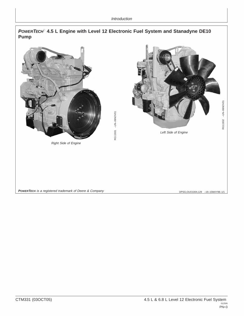
POWERTECH 4.5 L Engine with Level 12 Electronic Fuel System and Stanadyne DE10Pump
RG
1193
1–U
N–0
6NO
V01
Right Side of Engine
RG
1193
2–U
N–0
6NO
V01
Left Side of Engine
POWERTECH is a registered trademark of Deere & Company
CTM331 (03OCT05) 4.5 L & 6.8 L Level 12 Electronic Fuel System012506
PN=3
Introduction
CTM331 (03OCT05) 4.5 L & 6.8 L Level 12 Electronic Fuel System012506
PN=4
Contents01
SECTION 01—General InformationGroup 000—SafetyGroup 001—Engine IdentificationGroup 002—Fuels
02SECTION 02—Repair and AdjustmentsGroup 090—Electronic Fuel System Repair and
AdjustmentsGroup 110—Electrical Engine Control Repair and
Adjustment
SECTION 03—Theory of OperationGroup 130—Electronic Fuel System OperationGroup 140—Electronic Control System Operation
SECTION 04—Diagnostics
03
Group 150—Observable Diagnostics and TestsGroup 160—Trouble Code Diagnostics and Tests
SECTION 05—Tools and Other MaterialsGroup 170—Electronic Fuel/Control System Repair
Tools and Other MaterialsGroup 180—Diagnostic Service Tools
SECTION 06—SpecificationsGroup 200—Repair SpecificationsGroup 210—Diagnostic Specifications
04
05
All information, illustrations and specifications in this manual are based onthe latest information available at the time of publication. The right isreserved to make changes at any time without notice.
06
COPYRIGHT 2002DEERE & COMPANY
Moline, IllinoisAll rights reserved
A John Deere ILLUSTRUCTION Manual
INDX
CTM331 (03OCT05) i 4.5 L & 6.8 L Level 12 Electronic Fuel System012506
PN=1
Contents
01
02
03
04
05
06
INDX
CTM331 (03OCT05) ii 4.5 L & 6.8 L Level 12 Electronic Fuel System012506
PN=2
01
Section 01General Information
Contents
Page
Group 000—Safety . . . . . . . . . . . . . . . . . . . .01-000-1
Group 001—Engine IdentificationEngine Model Designation. . . . . . . . . . . . . . . .01-001-1Engine Serial Number Plate Information . . . . .01-001-2OEM Engine Option Code Label . . . . . . . . . . .01-001-3Information Relative to Emissions
Regulations . . . . . . . . . . . . . . . . . . . . . . . . .01-001-3Engine Application Charts . . . . . . . . . . . . . . . .01-001-4
Group 002—FuelsLubricants and Coolant . . . . . . . . . . . . . . . . . .01-002-1Diesel Fuel . . . . . . . . . . . . . . . . . . . . . . . . . . .01-002-1Bio-Diesel Fuel . . . . . . . . . . . . . . . . . . . . . . . .01-002-2Testing Diesel Fuel . . . . . . . . . . . . . . . . . . . . .01-002-2Lubricity of Diesel Fuel . . . . . . . . . . . . . . . . . .01-002-3
CTM331 (03OCT05) 01-1 4.5 L & 6.8 L Level 12 Electronic Fuel System012506
PN=1
Contents
01
CTM331 (03OCT05) 01-2 4.5 L & 6.8 L Level 12 Electronic Fuel System012506
PN=2
Group 000Safety
010001
DX,FLAME –19–29SEP98–1/1
Handle Fluids Safely—Avoid Fires
TS
227
–UN
–23A
UG
88
When you work around fuel, do not smoke or work nearheaters or other fire hazards.
Store flammable fluids away from fire hazards. Do notincinerate or puncture pressurized containers.
Make sure machine is clean of trash, grease, and debris.
Do not store oily rags; they can ignite and burnspontaneously.
DX,FIRE3 –19–16APR92–1/1
Handle Starting Fluid Safely
TS
1356
–UN
–18M
AR
92
Starting fluid is highly flammable.
Keep all sparks and flame away when using it. Keepstarting fluid away from batteries and cables.
To prevent accidental discharge when storing thepressurized can, keep the cap on the container, and storein a cool, protected location.
Do not incinerate or puncture a starting fluid container.
DX,FIRE2 –19–03MAR93–1/1
Prepare for Emergencies
TS
291
–UN
–23A
UG
88
Be prepared if a fire starts.
Keep a first aid kit and fire extinguisher handy.
Keep emergency numbers for doctors, ambulance service,hospital, and fire department near your telephone.
CTM331 (03OCT05) 01-000-1 4.5 L & 6.8 L Level 12 Electronic Fuel System012506
PN=9
Safety
01000
2
DX,FLUID –19–03MAR93–1/1
Avoid High-Pressure Fluids
X98
11–U
N–2
3AU
G88
Escaping fluid under pressure can penetrate the skincausing serious injury.
Avoid the hazard by relieving pressure beforedisconnecting hydraulic or other lines. Tighten allconnections before applying pressure.
Search for leaks with a piece of cardboard. Protect handsand body from high pressure fluids.
If an accident occurs, see a doctor immediately. Any fluidinjected into the skin must be surgically removed within afew hours or gangrene may result. Doctors unfamiliar withthis type of injury should reference a knowledgeablemedical source. Such information is available from Deere& Company Medical Department in Moline, Illinois, U.S.A.
DX,WEAR –19–10SEP90–1/1
Wear Protective Clothing
TS
206
–UN
–23A
UG
88
Wear close fitting clothing and safety equipmentappropriate to the job.
Prolonged exposure to loud noise can cause impairmentor loss of hearing.
Wear a suitable hearing protective device such asearmuffs or earplugs to protect against objectionable oruncomfortable loud noises.
Operating equipment safely requires the full attention ofthe operator. Do not wear radio or music headphoneswhile operating machine.
CTM331 (03OCT05) 01-000-2 4.5 L & 6.8 L Level 12 Electronic Fuel System012506
PN=10
Safety
010003
DX,LOOSE –19–04JUN90–1/1
Service Machines Safely
TS
228
–UN
–23A
UG
88
Tie long hair behind your head. Do not wear a necktie,scarf, loose clothing, or necklace when you work nearmachine tools or moving parts. If these items were to getcaught, severe injury could result.
Remove rings and other jewelry to prevent electricalshorts and entanglement in moving parts.
DX,AIR –19–17FEB99–1/1
Work In Ventilated Area
TS
220
–UN
–23A
UG
88
Engine exhaust fumes can cause sickness or death. If it isnecessary to run an engine in an enclosed area, removethe exhaust fumes from the area with an exhaust pipeextension.
If you do not have an exhaust pipe extension, open thedoors and get outside air into the area
DX,CLEAN –19–04JUN90–1/1
Work in Clean Area
T66
42E
J–U
N–1
8OC
T88
Before starting a job:
• Clean work area and machine.• Make sure you have all necessary tools to do your job.• Have the right parts on hand.• Read all instructions thoroughly; do not attempt
shortcuts.
CTM331 (03OCT05) 01-000-3 4.5 L & 6.8 L Level 12 Electronic Fuel System012506
PN=11
Safety
01000
4
DX,PAINT –19–24JUL02–1/1
Remove Paint Before Welding or Heating
TS
220
–UN
–23A
UG
88
Avoid potentially toxic fumes and dust.
Hazardous fumes can be generated when paint is heatedby welding, soldering, or using a torch.
Remove paint before heating:
• Remove paint a minimum of 100 mm (4 in.) from areato be affected by heating. If paint cannot be removed,wear an approved respirator before heating or welding.
• If you sand or grind paint, avoid breathing the dust.Wear an approved respirator.
• If you use solvent or paint stripper, remove stripper withsoap and water before welding. Remove solvent orpaint stripper containers and other flammable materialfrom area. Allow fumes to disperse at least 15 minutesbefore welding or heating.
Do not use a chlorinated solvent in areas where weldingwill take place.
Do all work in an area that is well ventilated to carry toxicfumes and dust away.
Dispose of paint and solvent properly.
DX,TORCH –19–10DEC04–1/1
Avoid Heating Near Pressurized Fluid Lines
TS
953
–UN
–15M
AY
90Flammable spray can be generated by heating nearpressurized fluid lines, resulting in severe burns toyourself and bystanders. Do not heat by welding,soldering, or using a torch near pressurized fluid lines orother flammable materials. Pressurized lines canaccidentally burst when heat goes beyond the immediateflame area.
CTM331 (03OCT05) 01-000-4 4.5 L & 6.8 L Level 12 Electronic Fuel System012506
PN=12
Safety
010005
DX,LIGHT –19–04JUN90–1/1
Illuminate Work Area Safely
TS
223
–UN
–23A
UG
88
Illuminate your work area adequately but safely. Use aportable safety light for working inside or under themachine. Make sure the bulb is enclosed by a wire cage.The hot filament of an accidentally broken bulb can ignitespilled fuel or oil.
DX,SAFE,TOOLS –19–10OCT97–1/1
Construct Dealer-Made Tools Safely
LX10
1674
9–U
N–0
1JU
L97
Faulty or broken tools can result in serious injury. Whenconstructing tools, use proper, quality materials, and goodworkmanship.
Do not weld tools unless you have the proper equipmentand experience to perform the job.
CTM331 (03OCT05) 01-000-5 4.5 L & 6.8 L Level 12 Electronic Fuel System012506
PN=13
Safety
01000
6
DX,SERV –19–17FEB99–1/1
Practice Safe Maintenance
TS
218
–UN
–23A
UG
88
Understand service procedure before doing work. Keeparea clean and dry.
Never lubricate, service, or adjust machine while it ismoving. Keep hands, feet , and clothing frompower-driven parts. Disengage all power and operatecontrols to relieve pressure. Lower equipment to theground. Stop the engine. Remove the key. Allow machineto cool.
Securely support any machine elements that must beraised for service work.
Keep all parts in good condition and properly installed. Fixdamage immediately. Replace worn or broken parts.Remove any buildup of grease, oil, or debris.
On self-propelled equipment, disconnect battery groundcable (-) before making adjustments on electrical systemsor welding on machine.
On towed implements, disconnect wiring harnesses fromtractor before servicing electrical system components orwelding on machine.
DX,REPAIR –19–17FEB99–1/1
Use Proper Tools
TS
779
–UN
–08N
OV
89Use tools appropriate to the work. Makeshift tools andprocedures can create safety hazards.
Use power tools only to loosen threaded parts andfasteners.
For loosening and tightening hardware, use the correctsize tools. DO NOT use U.S. measurement tools onmetric fasteners. Avoid bodily injury caused by slippingwrenches.
Use only service parts meeting John Deere specifications.
CTM331 (03OCT05) 01-000-6 4.5 L & 6.8 L Level 12 Electronic Fuel System012506
PN=14
Safety
010007
DX,DRAIN –19–03MAR93–1/1
Dispose of Waste Properly
TS
1133
–UN
–26N
OV
90
Improperly disposing of waste can threaten theenvironment and ecology. Potentially harmful waste usedwith John Deere equipment include such items as oil, fuel,coolant, brake fluid, filters, and batteries.
Use leakproof containers when draining fluids. Do not usefood or beverage containers that may mislead someoneinto drinking from them.
Do not pour waste onto the ground, down a drain, or intoany water source.
Air conditioning refrigerants escaping into the air candamage the Earth’s atmosphere. Government regulationsmay require a certified air conditioning service center torecover and recycle used air conditioning refrigerants.
Inquire on the proper way to recycle or dispose of wastefrom your local environmental or recycling center, or fromyour John Deere dealer.
DX,LIVE –19–25SEP92–1/1
Live With Safety
TS
231
–19–
07O
CT
88
Before returning machine to customer, make suremachine is functioning properly, especially the safetysystems. Install all guards and shields.
CTM331 (03OCT05) 01-000-7 4.5 L & 6.8 L Level 12 Electronic Fuel System012506
PN=15
Safety
01000
8
CTM331 (03OCT05) 01-000-8 4.5 L & 6.8 L Level 12 Electronic Fuel System012506
PN=16
Group 001Engine Identification
010011
OUO1080,00001FA –19–15NOV01–1/1
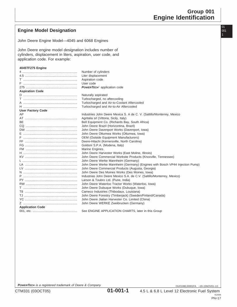
Engine Model Designation
John Deere Engine Model—4045 and 6068 Engines
John Deere engine model designation includes number ofcylinders, displacement in liters, aspiration, user code, andapplication code. For example:
4045TF275 Engine4 ................................................................ Number of cylinders4.5 ............................................................. Liter displacementT ............................................................... Aspiration codeF ............................................................... User code275 ............................................................ POWERTECH application codeAspiration CodeD ............................................................... Naturally aspiratedT ............................................................... Turbocharged, no aftercoolingA ............................................................... Turbocharged and Air-to-Coolant AftercooledH ............................................................... Turbocharged and Air-to-Air AftercooledUser Factory CodeAP Industries John Deere Mexica S. A de C. V. (Saltillo/Monterrey, MexicoAT ............................................................. Agritalia srl (Vittoria, Sicily, Italy)BE Bell Equipment Co. (Richards Bay, South Africa)CQ ............................................................ John Deere Brazil (Horizontina, Brazil)DW ............................................................ John Deere Davenport Works (Davenport, Iowa)E ............................................................... John Deere Ottumwa Works (Ottumwa, Iowa)F ............................................................... OEM (Outside Equipment Manufacturers)FF ............................................................. Deere-Hitachi (Kernersville, North Carolina)FG ............................................................. Goldoni S.P.A. (Modena, Italy)FM ............................................................ Marine EnginesH ............................................................... John Deere Harvester Works (East Moline, Illinois)KV ............................................................. John Deere Commercial Worksite Products (Knoxville, Tennessee)L ................................................................ John Deere Werke Mannheim (Germany)LA ............................................................. John Deere Werke Mannheim (Germany) (Engines with Bosch VP44 Injection Pump)LV ............................................................. John Deere Commercial Products (Augusta, Georgia)N ............................................................... John Deere Des Moines Works (Des Moines, Iowa)P ............................................................... Industrias John Deere Mexico S.A. de C.V. (Saltillo/Monterrey, Mexico)PY ............................................................. Larson & Toubro Ltd. (Pune, India)RW ............................................................ John Deere Waterloo Tractor Works (Waterloo, Iowa)T ............................................................... John Deere Dubuque Works (Dubuque, Iowa)T8 ............................................................. Cameco Industries (Thibodaux, Louisiana)TJ .............................................................. John Deere Forestry (Timberjack) (Sweden/Finland/Canada)YC ............................................................. John Deere Jialian Harvester Co. Limited (China)Z ............................................................... John Deere WERKE Zweibrucken (Germany)Application Code001, etc. .................................................... See ENGINE APPLICATION CHARTS, later in this Group
POWERTECH is a registered trademark of Deere & Company
CTM331 (03OCT05) 01-001-1 4.5 L & 6.8 L Level 12 Electronic Fuel System012506
PN=17
Engine Identification
01001
2
OUO1080,00001FB –19–15NOV01–1/1
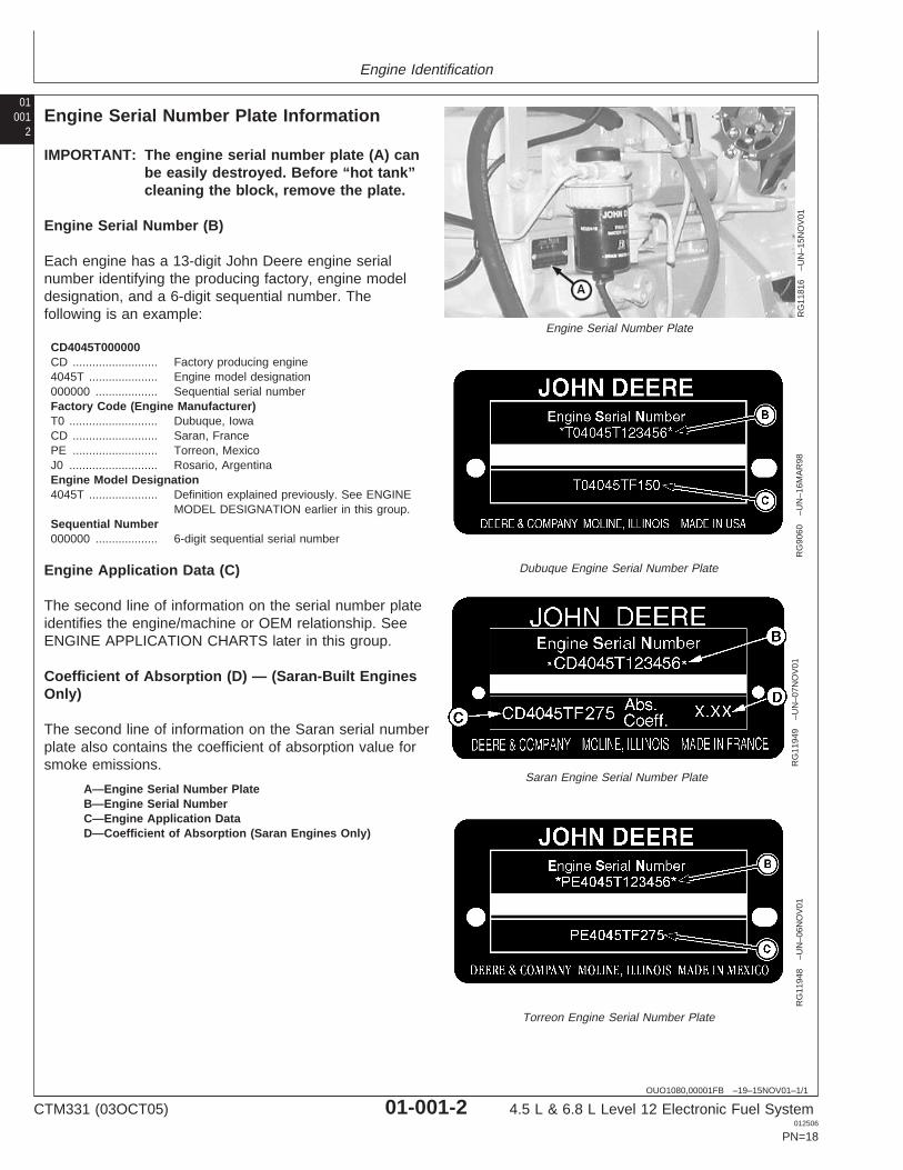
Engine Serial Number Plate Information
RG
1181
6–U
N–1
5NO
V01
Engine Serial Number Plate
RG
9060
–UN
–16M
AR
98
Dubuque Engine Serial Number Plate
RG
1194
9–U
N–0
7NO
V01
Saran Engine Serial Number Plate
RG
1194
8–U
N–0
6NO
V01
Torreon Engine Serial Number Plate
A—Engine Serial Number PlateB—Engine Serial NumberC—Engine Application DataD—Coefficient of Absorption (Saran Engines Only)
IMPORTANT: The engine serial number plate (A) canbe easily destroyed. Before “hot tank”cleaning the block, remove the plate.
Engine Serial Number (B)
Each engine has a 13-digit John Deere engine serialnumber identifying the producing factory, engine modeldesignation, and a 6-digit sequential number. Thefollowing is an example:
CD4045T000000CD .......................... Factory producing engine4045T ..................... Engine model designation000000 ................... Sequential serial numberFactory Code (Engine Manufacturer)T0 ........................... Dubuque, IowaCD .......................... Saran, FrancePE .......................... Torreon, MexicoJ0 ........................... Rosario, ArgentinaEngine Model Designation4045T ..................... Definition explained previously. See ENGINE
MODEL DESIGNATION earlier in this group.Sequential Number000000 ................... 6-digit sequential serial number
Engine Application Data (C)
The second line of information on the serial number plateidentifies the engine/machine or OEM relationship. SeeENGINE APPLICATION CHARTS later in this group.
Coefficient of Absorption (D) — (Saran-Built EnginesOnly)
The second line of information on the Saran serial numberplate also contains the coefficient of absorption value forsmoke emissions.
CTM331 (03OCT05) 01-001-2 4.5 L & 6.8 L Level 12 Electronic Fuel System012506
PN=18
Engine Identification
010013
OUO1080,000020E –19–26NOV01–1/1
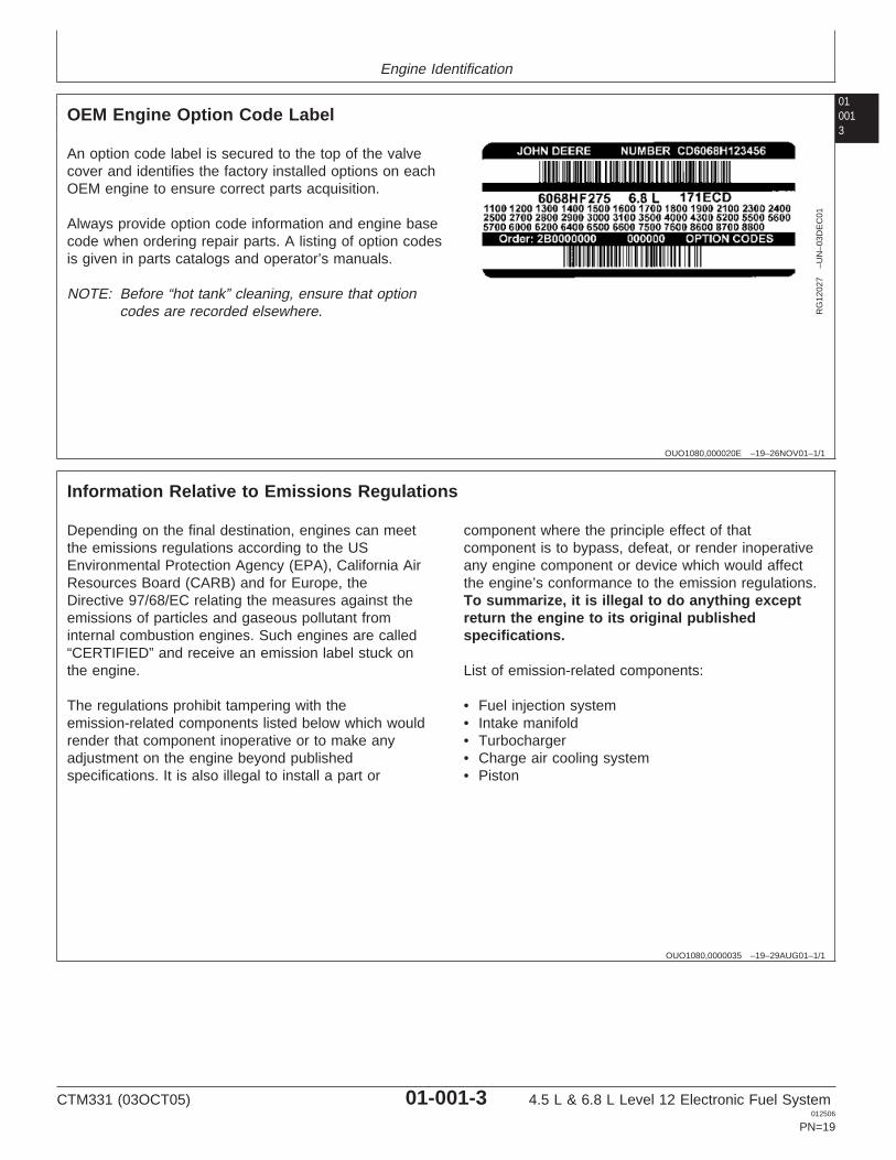
OEM Engine Option Code Label
RG
1202
7–U
N–0
3DE
C01
An option code label is secured to the top of the valvecover and identifies the factory installed options on eachOEM engine to ensure correct parts acquisition.
Always provide option code information and engine basecode when ordering repair parts. A listing of option codesis given in parts catalogs and operator’s manuals.
NOTE: Before “hot tank” cleaning, ensure that optioncodes are recorded elsewhere.
OUO1080,0000035 –19–29AUG01–1/1
Information Relative to Emissions Regulations
Depending on the final destination, engines can meetthe emissions regulations according to the USEnvironmental Protection Agency (EPA), California AirResources Board (CARB) and for Europe, theDirective 97/68/EC relating the measures against theemissions of particles and gaseous pollutant frominternal combustion engines. Such engines are called“CERTIFIED” and receive an emission label stuck onthe engine.
The regulations prohibit tampering with theemission-related components listed below which wouldrender that component inoperative or to make anyadjustment on the engine beyond publishedspecifications. It is also illegal to install a part or
component where the principle effect of thatcomponent is to bypass, defeat, or render inoperativeany engine component or device which would affectthe engine’s conformance to the emission regulations.To summarize, it is illegal to do anything exceptreturn the engine to its original publishedspecifications.
List of emission-related components:
• Fuel injection system• Intake manifold• Turbocharger• Charge air cooling system• Piston
CTM331 (03OCT05) 01-001-3 4.5 L & 6.8 L Level 12 Electronic Fuel System012506
PN=19
Engine Identification
01001
4
OUO1089,0000205 –19–23SEP05–1/2
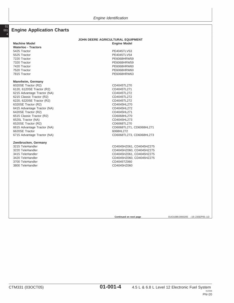
Engine Application Charts
JOHN DEERE AGRICULTURAL EQUIPMENTMachine Model Engine ModelWaterloo - Tractors5425 Tractor PE4045TLV535525 Tractor PE4045TLV547220 Tractor PE6068HRW597320 Tractor PE6068HRW597420 Tractor PE6068HRW607520 Tractor PE6068HRW607815 Tractor PE6068HRW63
Mannheim, Germany6020SE Tractor (R2) CD4045TL2706120, 6120SE Tractor (R2) CD4045TL2716215 Advantage Tractor (NA) CD4045TL2726215 Classic Tractor (R2) CD4045TL2726220, 6220SE Tractor (R2) CD4045TL2726320SE Tractor (R2) CD4045HL2706415 Advantage Tractor (NA) CD4045HL2726420SE Tractor (R2) CD4045HL2716515 Classic Tractor (R2) CD6068HL2706520L Tractor (NA) CD4045HL2736520SE Tractor (R2) CD6068TL2706615 Advantage Tractor (NA) CD6068TL271, CD6068HL2716620SE Tractor 6068HL2726715 Advantage Tractor (NA) CD6068TL273, CD6068HL273
Zweibrucken, Germany3215 TeleHandler CD4045HZ061, CD4045HZ2753220 TeleHandler CD4045HZ060, CD4045HZ2753415 TeleHandler CD4045HZ061, CD4045HZ2753420 TeleHandler CD4045HZ060, CD4045HZ2753700 TeleHandler CD4045TZ0603800 TeleHandler CD4045HZ060
Continued on next page
CTM331 (03OCT05) 01-001-4 4.5 L & 6.8 L Level 12 Electronic Fuel System012506
PN=20
Engine Identification
010015
OUO1089,0000205 –19–23SEP05–2/2
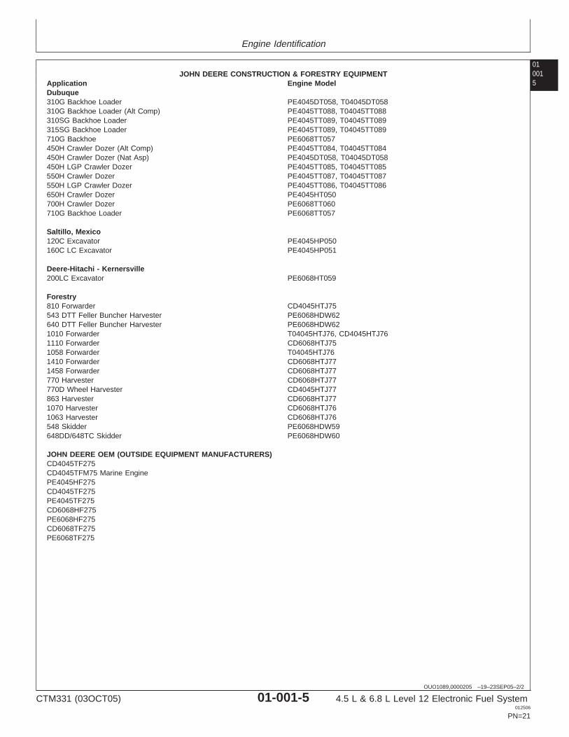
JOHN DEERE CONSTRUCTION & FORESTRY EQUIPMENTApplication Engine ModelDubuque310G Backhoe Loader PE4045DT058, T04045DT058310G Backhoe Loader (Alt Comp) PE4045TT088, T04045TT088310SG Backhoe Loader PE4045TT089, T04045TT089315SG Backhoe Loader PE4045TT089, T04045TT089710G Backhoe PE6068TT057450H Crawler Dozer (Alt Comp) PE4045TT084, T04045TT084450H Crawler Dozer (Nat Asp) PE4045DT058, T04045DT058450H LGP Crawler Dozer PE4045TT085, T04045TT085550H Crawler Dozer PE4045TT087, T04045TT087550H LGP Crawler Dozer PE4045TT086, T04045TT086650H Crawler Dozer PE4045HT050700H Crawler Dozer PE6068TT060710G Backhoe Loader PE6068TT057
Saltillo, Mexico120C Excavator PE4045HP050160C LC Excavator PE4045HP051
Deere-Hitachi - Kernersville200LC Excavator PE6068HT059
Forestry810 Forwarder CD4045HTJ75543 DTT Feller Buncher Harvester PE6068HDW62640 DTT Feller Buncher Harvester PE6068HDW621010 Forwarder T04045HTJ76, CD4045HTJ761110 Forwarder CD6068HTJ751058 Forwarder T04045HTJ761410 Forwarder CD6068HTJ771458 Forwarder CD6068HTJ77770 Harvester CD6068HTJ77770D Wheel Harvester CD4045HTJ77863 Harvester CD6068HTJ771070 Harvester CD6068HTJ761063 Harvester CD6068HTJ76548 Skidder PE6068HDW59648DD/648TC Skidder PE6068HDW60
JOHN DEERE OEM (OUTSIDE EQUIPMENT MANUFACTURERS)CD4045TF275CD4045TFM75 Marine EnginePE4045HF275CD4045TF275PE4045TF275CD6068HF275PE6068HF275CD6068TF275PE6068TF275
CTM331 (03OCT05) 01-001-5 4.5 L & 6.8 L Level 12 Electronic Fuel System012506
PN=21
Engine Identification
01001
6
CTM331 (03OCT05) 01-001-6 4.5 L & 6.8 L Level 12 Electronic Fuel System012506
PN=22
Group 002Fuels
010021
DPSG,OUO1004,2761 –19–16MAY00–1/1
Lubricants and Coolant
NOTE: Refer to Section 01, Group 002 of CTM104 BaseEngine Manual for information on lubricants andcoolants.
OUOD002,0000171 –19–23SEP05–1/1
Diesel Fuel
Consult your local fuel distributor for properties of thediesel fuel available in your area.
In general, diesel fuels are blended to satisfy the lowtemperature requirements of the geographical area inwhich they are marketed.
Diesel fuels specified to EN 590 or ASTM D975 arerecommended.
Required fuel properties
In all cases, the fuel must meet the followingproperties:
Cetane number of 45 minimum. Cetane numbergreater than 50 is preferred, especially fortemperatures below -20°C (-4°F) or elevations above1500 m (5000 ft).
Cold Filter Plugging Point (CFPP) below theexpected low temperature OR Cloud Point at least5°C (9°F) below the expected low temperature.
Fuel lubricity should pass a minimum load level of3100 grams as measured by ASTM D6078 or,maximum scar diameter of 0.45 mm as measured byASTM D6079.
Sulfur content:
• Diesel fuel quality and fuel sulfur content mustcomply with all existing regulations for the area inwhich the engine operates.
• Sulfur content less than 0.05% (500 ppm) ispreferred.
• If diesel fuel with sulfur content greater than 0.05%(500 ppm) is used, crankcase oil service intervalsmay be affected. (See recommendation for DieselEngine Oil.)
• DO NOT use diesel fuel with sulfur content greaterthan 1.0%.
IMPORTANT: DO NOT mix used engine oil or anyother type of lubricating oil withdiesel fuel.
CTM331 (03OCT05) 01-002-1 4.5 L & 6.8 L Level 12 Electronic Fuel System012506
PN=23
Fuels
01002
2
RG41183,0000046 –19–18DEC01–1/1
Bio-Diesel Fuel
Consult your local fuel distributor for properties of thebio-diesel fuel available in your area.
Bio-diesel fuels may be used ONLY if the bio-dieselfuel properties meet the latest edition of ASTM PS121,DIN 51606 or equivalent specification.
It has been found that bio-diesel fuels may improvelubricity in concentrations up to a 5% blend inpetroleum diesel fuel.
When using a blend of bio-diesel fuel, the engine oillevel must be checked daily when the air temperatureis -10°C (14°F) or lower. If the oil becomes diluted withfuel, shorten oil change intervals accordingly.
IMPORTANT: Raw pressed vegetable oils are NOTacceptable for use for fuel in anyconcentration in John Deereengines.
These oils do not burn completely,and will cause engine failure byleaving deposits on injectors and inthe combustion chamber.
A major environmental benefit of bio-diesel fuel is itsability to biodegrade. This makes proper storage andhandling of bio-diesel fuel especially important. Areasof concern include:
• Quality of new fuel• Water content of the fuel• Problems due to aging of the fuel
Potential problems resulting from deficiencies in theabove areas when using bio-diesel fuel inconcentrations above 5% may lead to the followingsymptoms:
• Power loss and deterioration of performance• Fuel leakage• Corrosion of fuel injection equipment• Coked and/or blocked injector nozzles, resulting in
engine misfire• Filter plugging• Lacquering and/or seizure of internal components• Sludge and sediments• Reduced service life of engine components
DX,FUEL6 –19–14NOV05–1/1
Testing Diesel Fuel
DIESELSCAN is a John Deere fuel analysis programthat can be used to monitor the quality of your fuel. TheDIESELSCAN analysis verifies fuel type, cleanliness,water content, suitability for cold weather operation, andwhether the fuel meets specifications.
Check with your John Deere dealer for availability ofDIESELSCAN kits.
DIESELSCAN is a trademark of Deere & Company
CTM331 (03OCT05) 01-002-2 4.5 L & 6.8 L Level 12 Electronic Fuel System012506
PN=24
Fuels
010023
OUOD002,0000179 –19–18DEC01–1/1
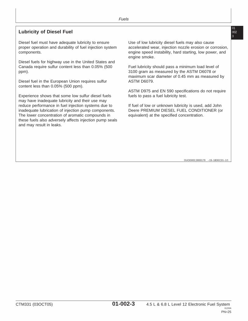
Lubricity of Diesel Fuel
Diesel fuel must have adequate lubricity to ensureproper operation and durability of fuel injection systemcomponents.
Diesel fuels for highway use in the United States andCanada require sulfur content less than 0.05% (500ppm).
Diesel fuel in the European Union requires sulfurcontent less than 0.05% (500 ppm).
Experience shows that some low sulfur diesel fuelsmay have inadequate lubricity and their use mayreduce performance in fuel injection systems due toinadequate lubrication of injection pump components.The lower concentration of aromatic compounds inthese fuels also adversely affects injection pump sealsand may result in leaks.
Use of low lubricity diesel fuels may also causeaccelerated wear, injection nozzle erosion or corrosion,engine speed instability, hard starting, low power, andengine smoke.
Fuel lubricity should pass a minimum load level of3100 gram as measured by the ASTM D6078 ormaximum scar diameter of 0.45 mm as measured byASTM D6079.
ASTM D975 and EN 590 specifications do not requirefuels to pass a fuel lubricity test.
If fuel of low or unknown lubricity is used, add JohnDeere PREMIUM DIESEL FUEL CONDITIONER (orequivalent) at the specified concentration.
CTM331 (03OCT05) 01-002-3 4.5 L & 6.8 L Level 12 Electronic Fuel System012506
PN=25
Fuels
01002
4
CTM331 (03OCT05) 01-002-4 4.5 L & 6.8 L Level 12 Electronic Fuel System012506
PN=26
Section 02Repair and AdjustmentsContents 02
Page Page
Group 090—Electronic Fuel System Repair and Remove Blade Terminals from ConnectorAdjustments Body . . . . . . . . . . . . . . . . . . . . . . . . . . . . .02-110-11
Fuel System—General Information . . . . . . . . .02-090-1 Repair (Pull Type) METRI-PACKRelieve Fuel System Pressure . . . . . . . . . . . .02-090-1 Connectors . . . . . . . . . . . . . . . . . . . . . . . .02-110-12Remove and Install Final Fuel Filter/Water Repair (Push Type) METRI-PACK
Bowl and/or Pre-Filter/Water Bowl Base . . .02-090-2 Connectors . . . . . . . . . . . . . . . . . . . . . . . .02-110-14Fuel Pre-Filter/Water Bowl Assembly Repair DEUTSCH Connectors . . . . . . . . . .02-110-17
(Optional). . . . . . . . . . . . . . . . . . . . . . . . . . .02-090-5 Repair AMP Connector . . . . . . . . . . . . . . . . .02-110-20Final Fuel Filter Assembly . . . . . . . . . . . . . . . .02-090-6Replace Final Fuel Filter/Water Bowl and
Pre-Filter/Water Bowl. . . . . . . . . . . . . . . . . .02-090-7Remove Fuel Supply Pump. . . . . . . . . . . . . . .02-090-9Install Fuel Supply Pump. . . . . . . . . . . . . . . .02-090-10Injection Pump Static Timing . . . . . . . . . . . . .02-090-10Remove Injection Pump . . . . . . . . . . . . . . . .02-090-11Inspect Injection Pump Drive Gear ID and
Shaft OD . . . . . . . . . . . . . . . . . . . . . . . . . .02-090-13Install Injection Pump . . . . . . . . . . . . . . . . . .02-090-13Remove Fuel Injection Nozzles . . . . . . . . . . .02-090-16Clean Fuel Injection Nozzle Bore . . . . . . . . .02-090-18Clean Fuel Injection Nozzles . . . . . . . . . . . . .02-090-18Fuel Injection Nozzle Test . . . . . . . . . . . . . . .02-090-19Disassemble Fuel Injection Nozzles . . . . . . .02-090-22Adjust Fuel Injection Nozzle . . . . . . . . . . . . .02-090-23Install Seals on Fuel Injection Nozzle . . . . . .02-090-24Install Fuel Injection Nozzles . . . . . . . . . . . . .02-090-25Bleed the Fuel System . . . . . . . . . . . . . . . . .02-090-26
Group 110—Electrical Engine Control Repair andAdjustment
Engine Control Unit (ECU) . . . . . . . . . . . . . . .02-110-1Remove and Install Engine Coolant
Temperature Sensor . . . . . . . . . . . . . . . . . .02-110-2Remove and Install Loss of Coolant
Temperature Sensor . . . . . . . . . . . . . . . . . .02-110-2Replace Crankshaft Position Sensor . . . . . . . .02-110-3Remove and Install Oil Pressure Sensor . . . . .02-110-3Remove and Install Manifold Air Temperature
Sensor . . . . . . . . . . . . . . . . . . . . . . . . . . . . .02-110-4Remove and Install Fuel Temperature
Sensor . . . . . . . . . . . . . . . . . . . . . . . . . . . . .02-110-4Remove and Install Fuel Heater . . . . . . . . . . .02-110-5Connectors . . . . . . . . . . . . . . . . . . . . . . . . . . .02-110-6Use Electrical Insulating Compound . . . . . . . .02-110-6Using High-Pressure Washer . . . . . . . . . . . . .02-110-7Repair WEATHERPACK Connector . . . . . . .02-110-8
CTM331 (03OCT05) 02-1 4.5 L & 6.8 L Level 12 Electronic Fuel System012506
PN=1
Contents
02
CTM331 (03OCT05) 02-2 4.5 L & 6.8 L Level 12 Electronic Fuel System012506
PN=2
Group 090Electronic Fuel System Repair and Adjustments
020901
OUO1089,00001F7 –19–06NOV01–1/1
Fuel System—General Information
Stanadyne DE10 pumps are static lock-pin timedduring installation of the injection pump.
The fuel supply pump is a separate componentmounted on upper right-hand side of engine block andis actuated by a pin in block that rides on enginecamshaft lobe.
Engines may be equipped with an optional fuelpre-filter/water bowl.
All engines are equipped with a round final fuel filterwith water bowl. Hand primer on top of filter element isoptional.
All engines use Stanadyne Rate Shaping Nozzles(RSN).
Field-installed options include fuel heater, water bowland hand fuel primer.
RG,35,JW7625 –19–20NOV97–1/1
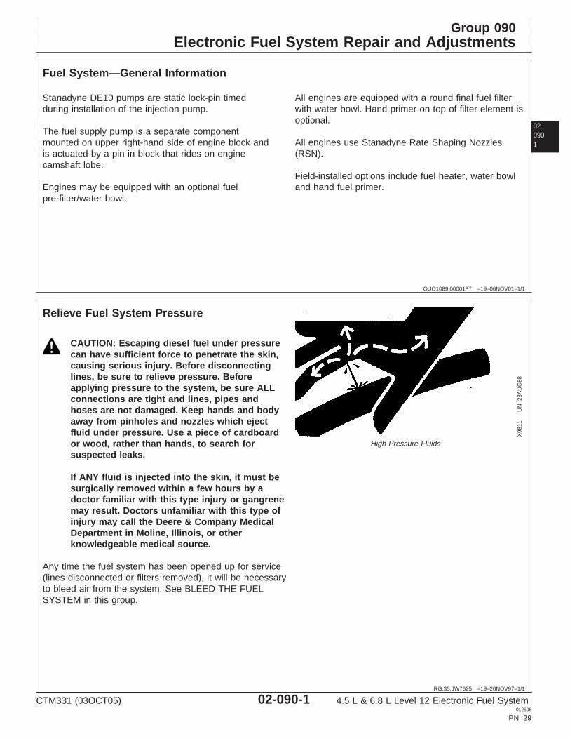
Relieve Fuel System Pressure
X98
11–U
N–2
3AU
G88
High Pressure Fluids
CAUTION: Escaping diesel fuel under pressurecan have sufficient force to penetrate the skin,causing serious injury. Before disconnectinglines, be sure to relieve pressure. Beforeapplying pressure to the system, be sure ALLconnections are tight and lines, pipes andhoses are not damaged. Keep hands and bodyaway from pinholes and nozzles which ejectfluid under pressure. Use a piece of cardboardor wood, rather than hands, to search forsuspected leaks.
If ANY fluid is injected into the skin, it must besurgically removed within a few hours by adoctor familiar with this type injury or gangrenemay result. Doctors unfamiliar with this type ofinjury may call the Deere & Company MedicalDepartment in Moline, Illinois, or otherknowledgeable medical source.
Any time the fuel system has been opened up for service(lines disconnected or filters removed), it will be necessaryto bleed air from the system. See BLEED THE FUELSYSTEM in this group.
CTM331 (03OCT05) 02-090-1 4.5 L & 6.8 L Level 12 Electronic Fuel System012506
PN=29
Electronic Fuel System Repair and Adjustments
02090
2
OUO1089,00001F6 –19–06NOV01–1/3
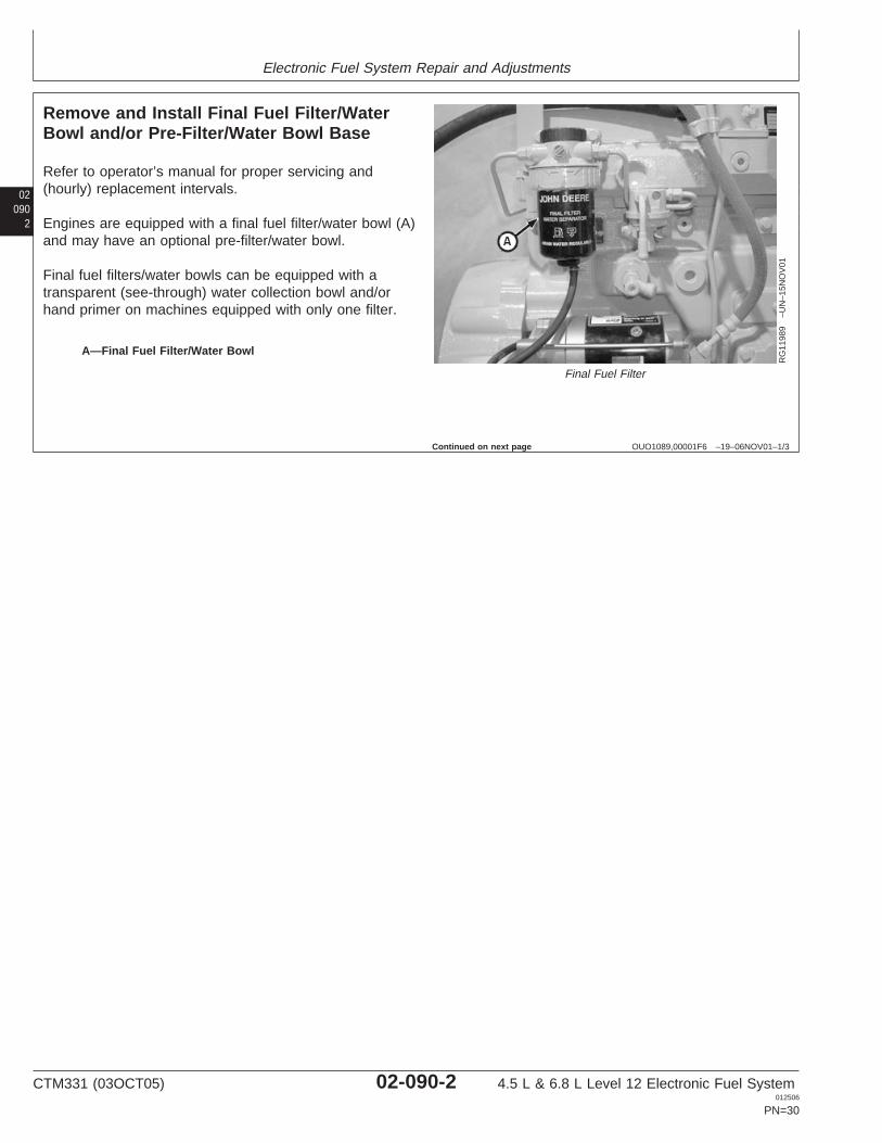
Remove and Install Final Fuel Filter/WaterBowl and/or Pre-Filter/Water Bowl Base
RG
1198
9–U
N–1
5NO
V01
Final Fuel Filter
A—Final Fuel Filter/Water Bowl
Refer to operator’s manual for proper servicing and(hourly) replacement intervals.
Engines are equipped with a final fuel filter/water bowl (A)and may have an optional pre-filter/water bowl.
Final fuel filters/water bowls can be equipped with atransparent (see-through) water collection bowl and/orhand primer on machines equipped with only one filter.
Continued on next page
CTM331 (03OCT05) 02-090-2 4.5 L & 6.8 L Level 12 Electronic Fuel System012506
PN=30
Electronic Fuel System Repair and Adjustments
020903
OUO1089,00001F6 –19–06NOV01–2/3
RG
1202
1–U
N–2
6NO
V01
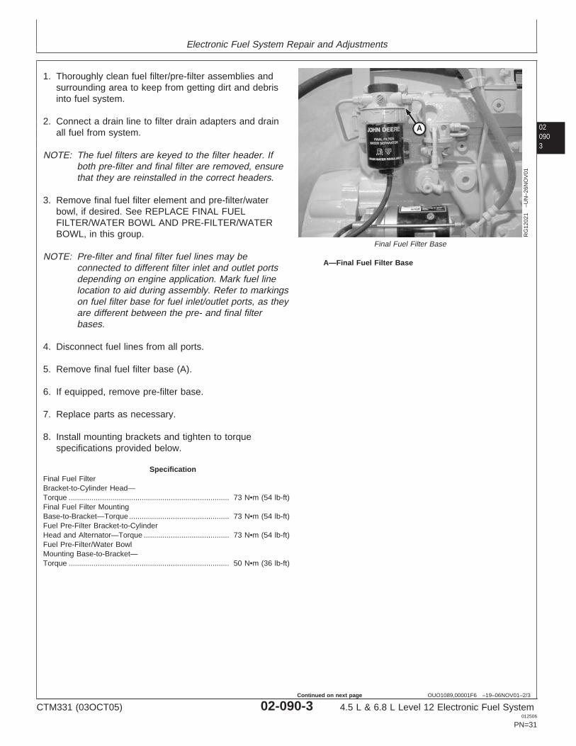
Final Fuel Filter Base
A—Final Fuel Filter Base
1. Thoroughly clean fuel filter/pre-filter assemblies andsurrounding area to keep from getting dirt and debrisinto fuel system.
2. Connect a drain line to filter drain adapters and drainall fuel from system.
NOTE: The fuel filters are keyed to the filter header. Ifboth pre-filter and final filter are removed, ensurethat they are reinstalled in the correct headers.
3. Remove final fuel filter element and pre-filter/waterbowl, if desired. See REPLACE FINAL FUELFILTER/WATER BOWL AND PRE-FILTER/WATERBOWL, in this group.
NOTE: Pre-filter and final filter fuel lines may beconnected to different filter inlet and outlet portsdepending on engine application. Mark fuel linelocation to aid during assembly. Refer to markingson fuel filter base for fuel inlet/outlet ports, as theyare different between the pre- and final filterbases.
4. Disconnect fuel lines from all ports.
5. Remove final fuel filter base (A).
6. If equipped, remove pre-filter base.
7. Replace parts as necessary.
8. Install mounting brackets and tighten to torquespecifications provided below.
SpecificationFinal Fuel FilterBracket-to-Cylinder Head—Torque 73 N•m (54 lb-ft).............................................................................Final Fuel Filter MountingBase-to-Bracket—Torque 73 N•m (54 lb-ft)................................................Fuel Pre-Filter Bracket-to-CylinderHead and Alternator—Torque 73 N•m (54 lb-ft).........................................Fuel Pre-Filter/Water BowlMounting Base-to-Bracket—Torque 50 N•m (36 lb-ft).............................................................................
CTM331 (03OCT05) 02-090-3 4.5 L & 6.8 L Level 12 Electronic Fuel System012506
PN=31
Continued on next page
Electronic Fuel System Repair and Adjustments
02090
4
OUO1089,00001F6 –19–06NOV01–3/3
9. Install pre-filter and final filter fuel filter/water bowlelements. See REPLACE FINAL FUELFILTER/WATER BOWL AND PRE-FILTER/WATERBOWL, in this group.
10. Connect fuel lines to all ports.
11. Bleed the fuel system. See BLEED THE FUELSYSTEM in this group.
CTM331 (03OCT05) 02-090-4 4.5 L & 6.8 L Level 12 Electronic Fuel System012506
PN=32
Electronic Fuel System Repair and Adjustments
020905
RG,35,JW7623 –19–21JAN02–1/1
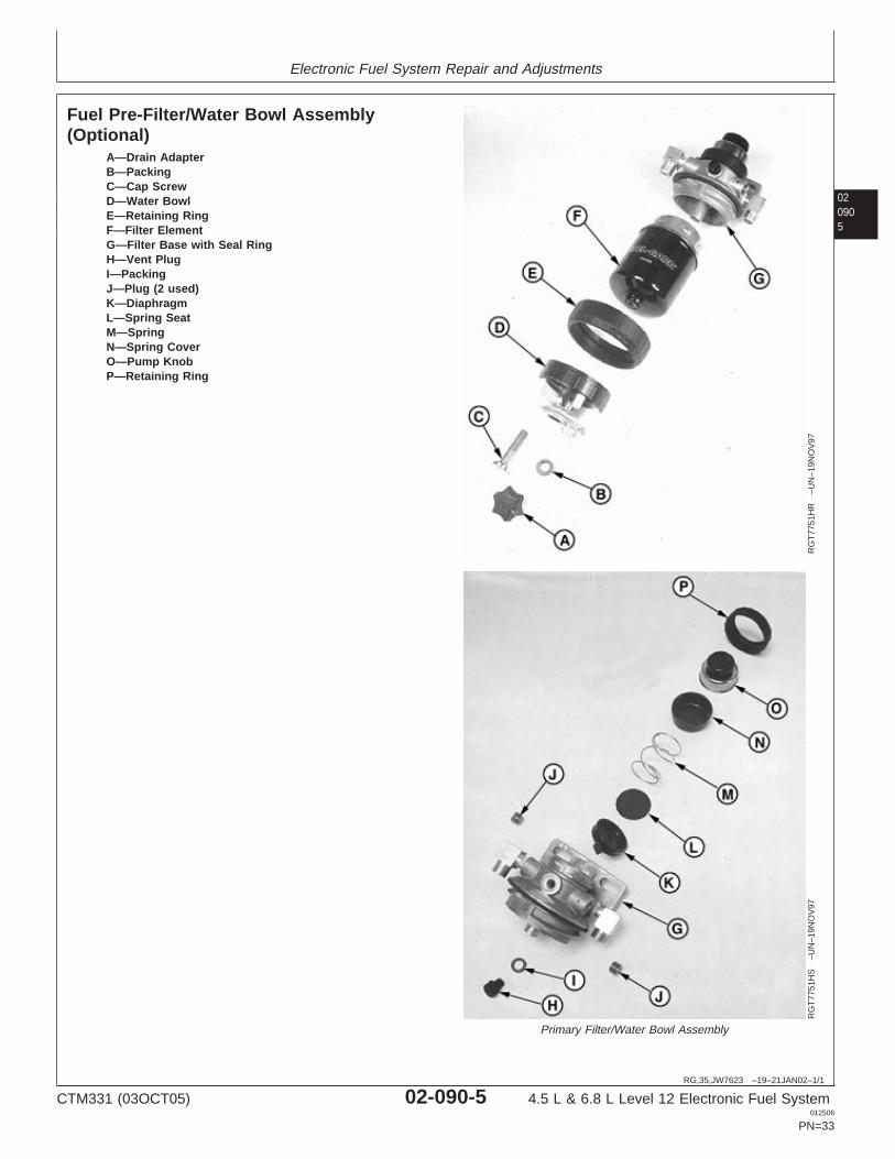
Fuel Pre-Filter/Water Bowl Assembly(Optional)
RG
T77
51H
R–U
N–1
9NO
V97
RG
T77
51H
S–U
N–1
9NO
V97
Primary Filter/Water Bowl Assembly
A—Drain AdapterB—PackingC—Cap ScrewD—Water BowlE—Retaining RingF—Filter ElementG—Filter Base with Seal RingH—Vent PlugI—PackingJ—Plug (2 used)K—DiaphragmL—Spring SeatM—SpringN—Spring CoverO—Pump KnobP—Retaining Ring
CTM331 (03OCT05) 02-090-5 4.5 L & 6.8 L Level 12 Electronic Fuel System012506
PN=33
Electronic Fuel System Repair and Adjustments
02090
6
OUO1080,00001FC –19–15NOV01–1/1
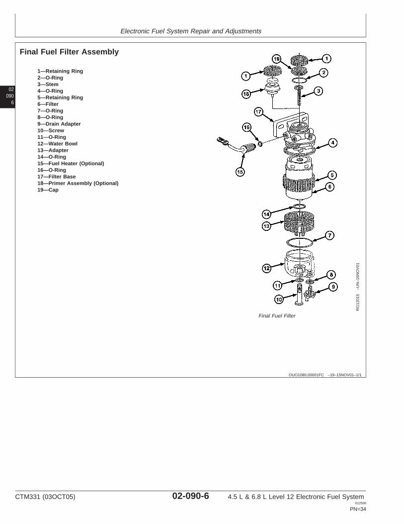
Final Fuel Filter Assembly
RG
1201
5–U
N–1
6NO
V01
Final Fuel Filter
1—Retaining Ring2—O-Ring3—Stem4—O-Ring5—Retaining Ring6—Filter7—O-Ring8—O-Ring9—Drain Adapter10—Screw11—O-Ring12—Water Bowl13—Adapter14—O-Ring15—Fuel Heater (Optional)16—O-Ring17—Filter Base18—Primer Assembly (Optional)19—Cap
CTM331 (03OCT05) 02-090-6 4.5 L & 6.8 L Level 12 Electronic Fuel System012506
PN=34
Electronic Fuel System Repair and Adjustments
020907
OUO1089,00001F5 –19–06NOV01–1/2
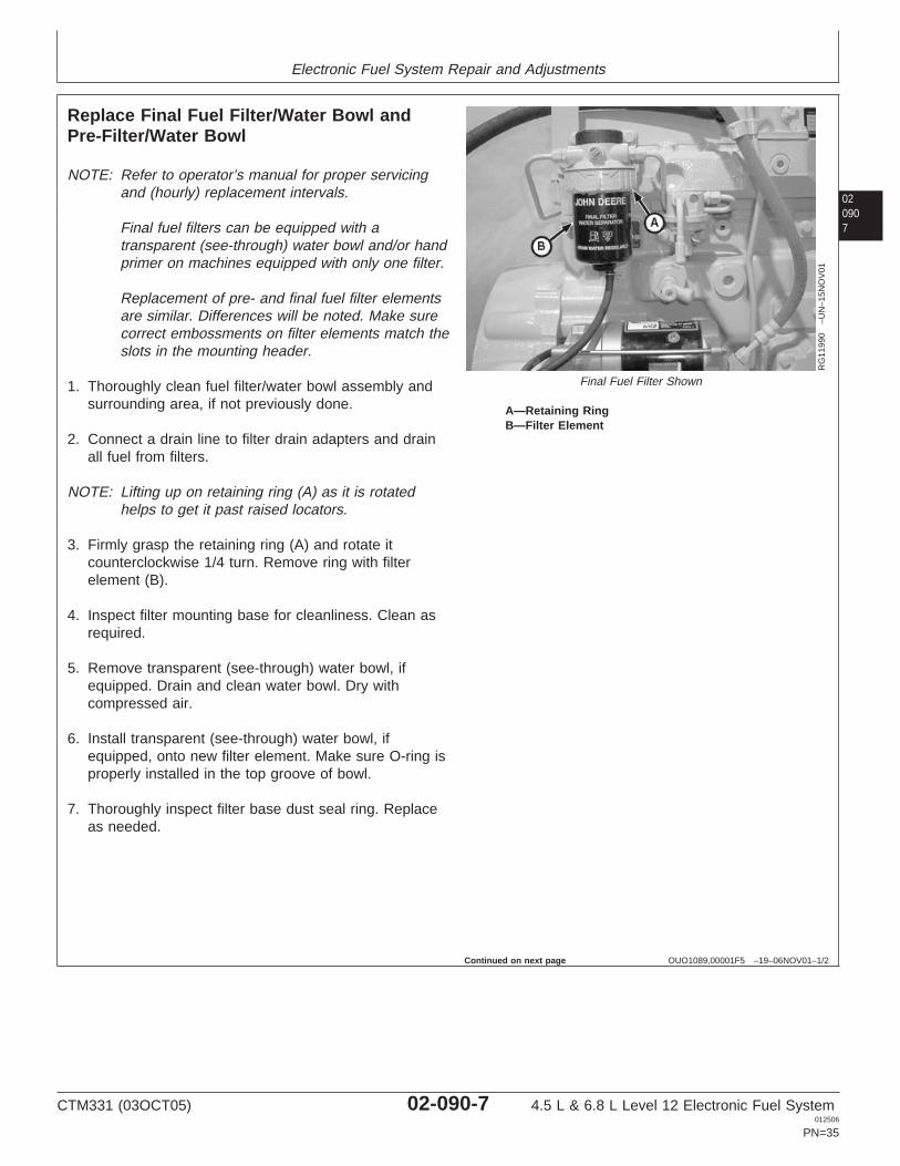
Replace Final Fuel Filter/Water Bowl andPre-Filter/Water Bowl
RG
1199
0–U
N–1
5NO
V01
Final Fuel Filter Shown
A—Retaining RingB—Filter Element
NOTE: Refer to operator’s manual for proper servicingand (hourly) replacement intervals.
Final fuel filters can be equipped with atransparent (see-through) water bowl and/or handprimer on machines equipped with only one filter.
Replacement of pre- and final fuel filter elementsare similar. Differences will be noted. Make surecorrect embossments on filter elements match theslots in the mounting header.
1. Thoroughly clean fuel filter/water bowl assembly andsurrounding area, if not previously done.
2. Connect a drain line to filter drain adapters and drainall fuel from filters.
NOTE: Lifting up on retaining ring (A) as it is rotatedhelps to get it past raised locators.
3. Firmly grasp the retaining ring (A) and rotate itcounterclockwise 1/4 turn. Remove ring with filterelement (B).
4. Inspect filter mounting base for cleanliness. Clean asrequired.
5. Remove transparent (see-through) water bowl, ifequipped. Drain and clean water bowl. Dry withcompressed air.
6. Install transparent (see-through) water bowl, ifequipped, onto new filter element. Make sure O-ring isproperly installed in the top groove of bowl.
7. Thoroughly inspect filter base dust seal ring. Replaceas needed.
Continued on next page
CTM331 (03OCT05) 02-090-7 4.5 L & 6.8 L Level 12 Electronic Fuel System012506
PN=35
Electronic Fuel System Repair and Adjustments
02090
8
OUO1089,00001F5 –19–06NOV01–2/2
NOTE: The fuel filters must be indexed properly and thekey on canister must be oriented in slot ofmounting base for correct installation.
8. Install new filter element onto mounting base andposition element using a slight rocking motion. Be sureelement is properly indexed on mounting base.
9. Install retaining ring onto mounting base and tightenabout 1/3 turn until ring “snaps” into the detent. DONOT overtighten the retaining ring.
10. Bleed fuel system. See BLEED THE FUEL SYSTEM,in this group.
CTM331 (03OCT05) 02-090-8 4.5 L & 6.8 L Level 12 Electronic Fuel System012506
PN=36
Electronic Fuel System Repair and Adjustments
020909
OUO1089,00001F8 –19–06NOV01–1/1
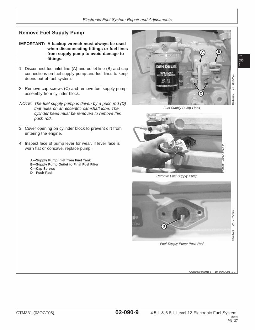
Remove Fuel Supply Pump
RG
1199
1–U
N–1
5NO
V01
Fuel Supply Pump Lines
RG
9051
–UN
–16M
AR
98
Remove Fuel Supply Pump
RG
1202
2–U
N–2
7NO
V01
Fuel Supply Pump Push Rod
A—Supply Pump Inlet from Fuel TankB—Supply Pump Outlet to Final Fuel FilterC—Cap ScrewsD—Push Rod
IMPORTANT: A backup wrench must always be usedwhen disconnecting fittings or fuel linesfrom supply pump to avoid damage tofittings.
1. Disconnect fuel inlet line (A) and outlet line (B) and capconnections on fuel supply pump and fuel lines to keepdebris out of fuel system.
2. Remove cap screws (C) and remove fuel supply pumpassembly from cylinder block.
NOTE: The fuel supply pump is driven by a push rod (D)that rides on an eccentric camshaft lobe. Thecylinder head must be removed to remove thispush rod.
3. Cover opening on cylinder block to prevent dirt fromentering the engine.
4. Inspect face of pump lever for wear. If lever face isworn flat or concave, replace pump.
CTM331 (03OCT05) 02-090-9 4.5 L & 6.8 L Level 12 Electronic Fuel System012506
PN=37
Electronic Fuel System Repair and Adjustments
02090
10
OUO1089,00001FA –19–06NOV01–1/1
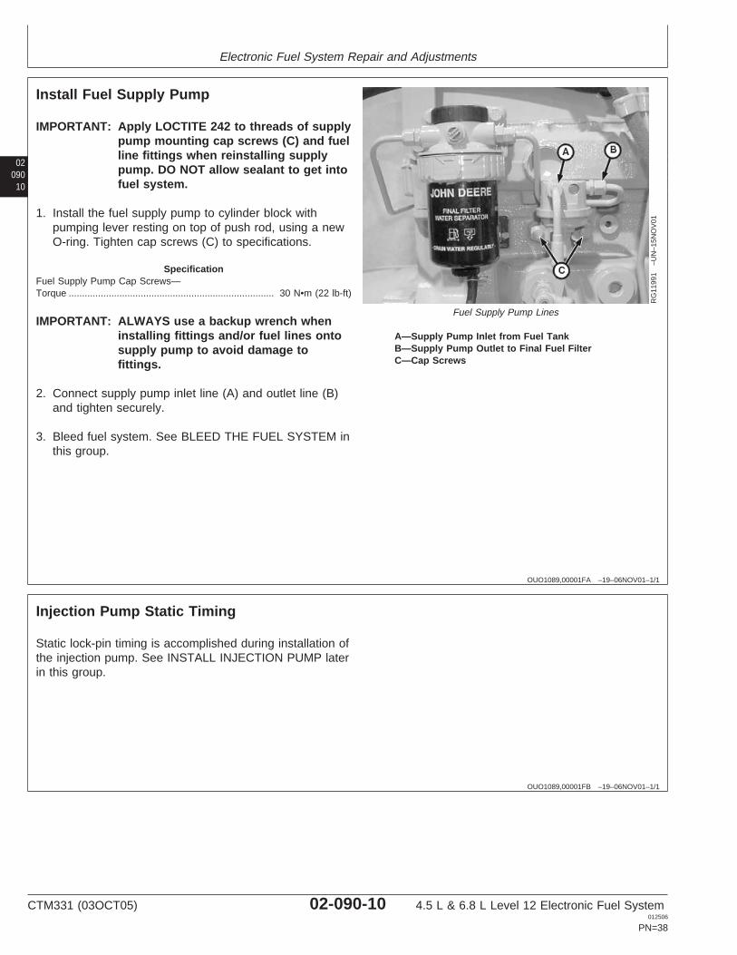
Install Fuel Supply Pump
RG
1199
1–U
N–1
5NO
V01
Fuel Supply Pump Lines
A—Supply Pump Inlet from Fuel TankB—Supply Pump Outlet to Final Fuel FilterC—Cap Screws
IMPORTANT: Apply LOCTITE 242 to threads of supplypump mounting cap screws (C) and fuelline fittings when reinstalling supplypump. DO NOT allow sealant to get intofuel system.
1. Install the fuel supply pump to cylinder block withpumping lever resting on top of push rod, using a newO-ring. Tighten cap screws (C) to specifications.
SpecificationFuel Supply Pump Cap Screws—Torque 30 N•m (22 lb-ft).............................................................................
IMPORTANT: ALWAYS use a backup wrench wheninstalling fittings and/or fuel lines ontosupply pump to avoid damage tofittings.
2. Connect supply pump inlet line (A) and outlet line (B)and tighten securely.
3. Bleed fuel system. See BLEED THE FUEL SYSTEM inthis group.
OUO1089,00001FB –19–06NOV01–1/1
Injection Pump Static Timing
Static lock-pin timing is accomplished during installation ofthe injection pump. See INSTALL INJECTION PUMP laterin this group.
CTM331 (03OCT05) 02-090-10 4.5 L & 6.8 L Level 12 Electronic Fuel System012506
PN=38
Electronic Fuel System Repair and Adjustments
0209011
OUO1089,00001FE –19–07NOV01–1/2
Remove Injection Pump
RG
1200
2–U
N–1
6NO
V01
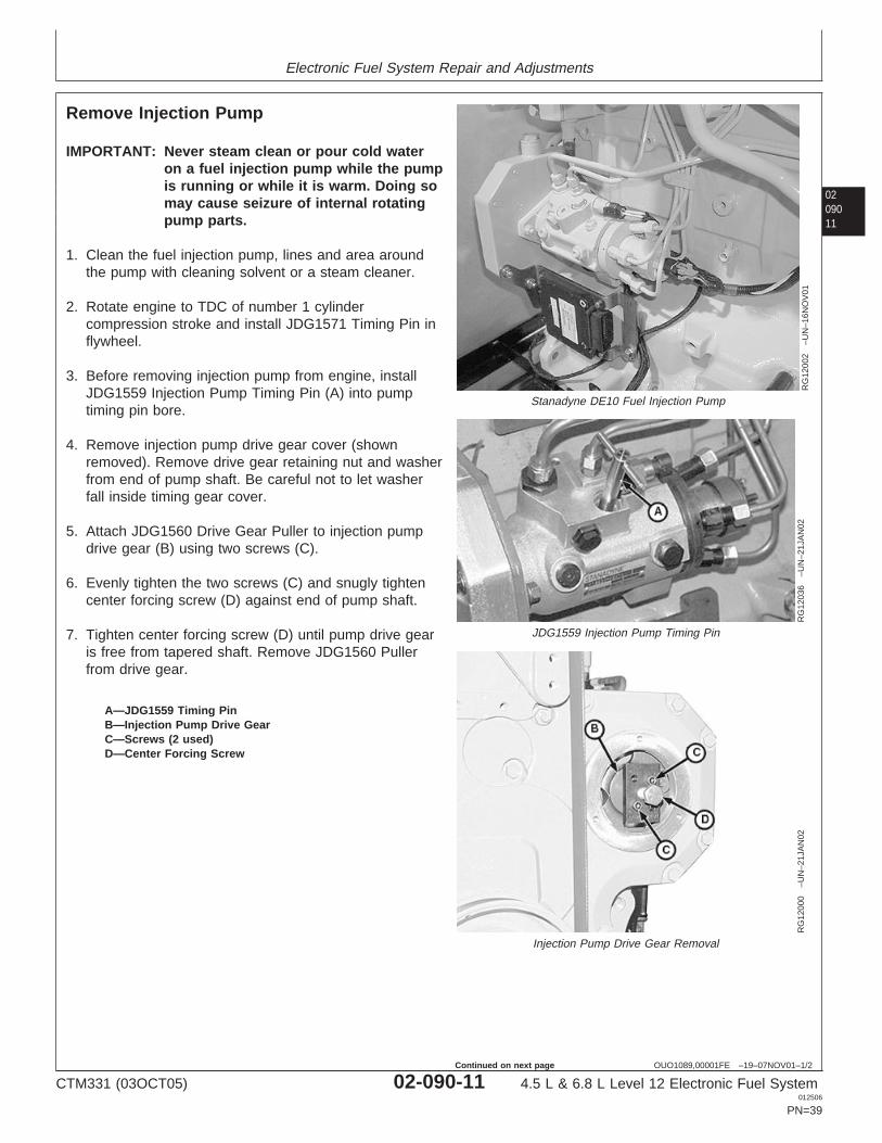
Stanadyne DE10 Fuel Injection Pump
RG
1203
6–U
N–2
1JA
N02
JDG1559 Injection Pump Timing Pin
RG
1200
0–U
N–2
1JA
N02
Injection Pump Drive Gear Removal
A—JDG1559 Timing PinB—Injection Pump Drive GearC—Screws (2 used)D—Center Forcing Screw
IMPORTANT: Never steam clean or pour cold wateron a fuel injection pump while the pumpis running or while it is warm. Doing somay cause seizure of internal rotatingpump parts.
1. Clean the fuel injection pump, lines and area aroundthe pump with cleaning solvent or a steam cleaner.
2. Rotate engine to TDC of number 1 cylindercompression stroke and install JDG1571 Timing Pin inflywheel.
3. Before removing injection pump from engine, installJDG1559 Injection Pump Timing Pin (A) into pumptiming pin bore.
4. Remove injection pump drive gear cover (shownremoved). Remove drive gear retaining nut and washerfrom end of pump shaft. Be careful not to let washerfall inside timing gear cover.
5. Attach JDG1560 Drive Gear Puller to injection pumpdrive gear (B) using two screws (C).
6. Evenly tighten the two screws (C) and snugly tightencenter forcing screw (D) against end of pump shaft.
7. Tighten center forcing screw (D) until pump drive gearis free from tapered shaft. Remove JDG1560 Pullerfrom drive gear.
CTM331 (03OCT05) 02-090-11 4.5 L & 6.8 L Level 12 Electronic Fuel System012506
PN=39
Continued on next page
Electronic Fuel System Repair and Adjustments
02090
12
OUO1089,00001FE –19–07NOV01–2/2
RG
1200
1–U
N–1
6NO
V01
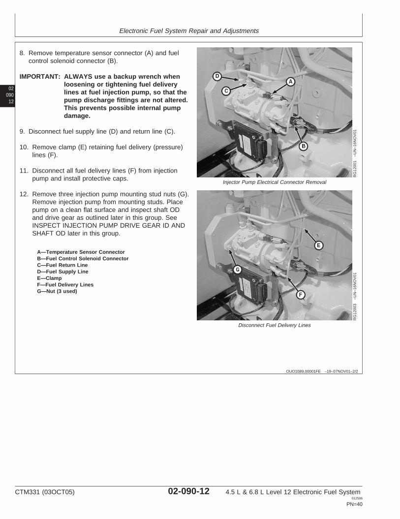
Injector Pump Electrical Connector Removal
RG
1200
3–U
N–1
6NO
V01
Disconnect Fuel Delivery Lines
A—Temperature Sensor ConnectorB—Fuel Control Solenoid ConnectorC—Fuel Return LineD—Fuel Supply LineE—ClampF—Fuel Delivery LinesG—Nut (3 used)
8. Remove temperature sensor connector (A) and fuelcontrol solenoid connector (B).
IMPORTANT: ALWAYS use a backup wrench whenloosening or tightening fuel deliverylines at fuel injection pump, so that thepump discharge fittings are not altered.This prevents possible internal pumpdamage.
9. Disconnect fuel supply line (D) and return line (C).
10. Remove clamp (E) retaining fuel delivery (pressure)lines (F).
11. Disconnect all fuel delivery lines (F) from injectionpump and install protective caps.
12. Remove three injection pump mounting stud nuts (G).Remove injection pump from mounting studs. Placepump on a clean flat surface and inspect shaft ODand drive gear as outlined later in this group. SeeINSPECT INJECTION PUMP DRIVE GEAR ID ANDSHAFT OD later in this group.
CTM331 (03OCT05) 02-090-12 4.5 L & 6.8 L Level 12 Electronic Fuel System012506
PN=40
Electronic Fuel System Repair and Adjustments
0209013
OUO1089,00001FC –19–06NOV01–1/1
Inspect Injection Pump Drive Gear ID and Shaft OD
IMPORTANT: Use a good light source tothoroughly inspect gear ID and shaftOD.
1. Inspect injection pump drive gear ID full 360° formetal transfer as a result of slippage on shaft.
2. Inspect injection pump drive shaft OD full 360° forpresence of metal transfer from gear slippage. Ifthere is clear evidence of metal transfer on pumpshaft OD or in drive gear ID, injection pump anddrive gear MUST BE replaced.
IMPORTANT: When replacing injection pump drivegear or installing a new pump, thetapered surfaces of the pump driveshaft OD and drive gear ID MUST BEcleaned to remove protectivecoatings and oily residue. Use asuitable cleaner that does not leavea residue. Mating surfaces MUST BEASSEMBLED DRY and LUBRICANTSMUST NOT BE USED.
OUO1089,0000204 –19–08NOV01–1/3
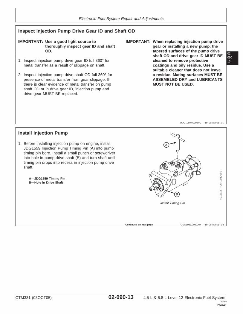
Install Injection Pump
B
A
RG
1201
9–U
N–1
9NO
V01
Install Timing Pin
A—JDG1559 Timing PinB—Hole in Drive Shaft
1. Before installing injection pump on engine, installJDG1559 Injection Pump Timing Pin (A) into pumptiming pin bore. Install a small punch or screwdriverinto hole in pump drive shaft (B) and turn shaft untiltiming pin drops into recess in injection pump driveshaft.
Continued on next page
CTM331 (03OCT05) 02-090-13 4.5 L & 6.8 L Level 12 Electronic Fuel System012506
PN=41
Electronic Fuel System Repair and Adjustments
02090
14
OUO1089,0000204 –19–08NOV01–2/3
RG
1200
4–U
N–1
6NO
V01
Injection Pump Mounting Stud Nuts
RG
1200
7–U
N–1
6NO
V01
Injection Pump Timing Pin
RG
1200
8–U
N–1
6NO
V01
Injection Pump Gear Installation
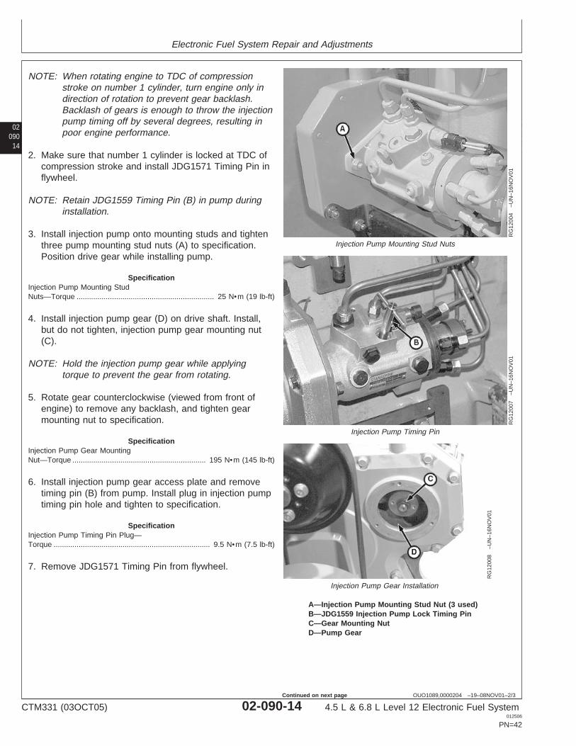
A—Injection Pump Mounting Stud Nut (3 used)B—JDG1559 Injection Pump Lock Timing PinC—Gear Mounting NutD—Pump Gear
NOTE: When rotating engine to TDC of compressionstroke on number 1 cylinder, turn engine only indirection of rotation to prevent gear backlash.Backlash of gears is enough to throw the injectionpump timing off by several degrees, resulting inpoor engine performance.
2. Make sure that number 1 cylinder is locked at TDC ofcompression stroke and install JDG1571 Timing Pin inflywheel.
NOTE: Retain JDG1559 Timing Pin (B) in pump duringinstallation.
3. Install injection pump onto mounting studs and tightenthree pump mounting stud nuts (A) to specification.Position drive gear while installing pump.
SpecificationInjection Pump Mounting StudNuts—Torque 25 N•m (19 lb-ft)..................................................................
4. Install injection pump gear (D) on drive shaft. Install,but do not tighten, injection pump gear mounting nut(C).
NOTE: Hold the injection pump gear while applyingtorque to prevent the gear from rotating.
5. Rotate gear counterclockwise (viewed from front ofengine) to remove any backlash, and tighten gearmounting nut to specification.
SpecificationInjection Pump Gear MountingNut—Torque 195 N•m (145 lb-ft)................................................................
6. Install injection pump gear access plate and removetiming pin (B) from pump. Install plug in injection pumptiming pin hole and tighten to specification.
SpecificationInjection Pump Timing Pin Plug—Torque 9.5 N•m (7.5 lb-ft)...........................................................................
7. Remove JDG1571 Timing Pin from flywheel.
CTM331 (03OCT05) 02-090-14 4.5 L & 6.8 L Level 12 Electronic Fuel System012506
PN=42
Continued on next page
Electronic Fuel System Repair and Adjustments
0209015
OUO1089,0000204 –19–08NOV01–3/3
RG
1200
1–U
N–1
6NO
V01
Injector Pump Electrical Connectors
RG
1200
3–U
N–1
6NO
V01
Connect Fuel Delivery Lines
RG
1203
5–U
N–1
1JA
N02
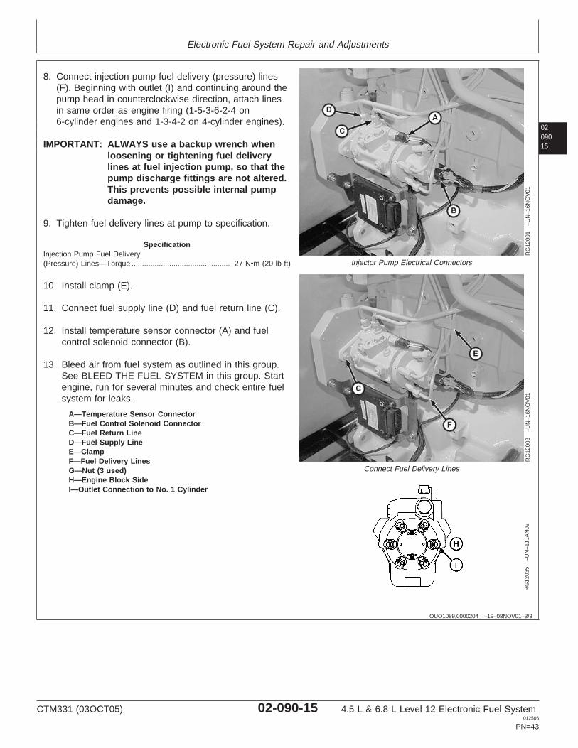
A—Temperature Sensor ConnectorB—Fuel Control Solenoid ConnectorC—Fuel Return LineD—Fuel Supply LineE—ClampF—Fuel Delivery LinesG—Nut (3 used)H—Engine Block SideI—Outlet Connection to No. 1 Cylinder
8. Connect injection pump fuel delivery (pressure) lines(F). Beginning with outlet (I) and continuing around thepump head in counterclockwise direction, attach linesin same order as engine firing (1-5-3-6-2-4 on6-cylinder engines and 1-3-4-2 on 4-cylinder engines).
IMPORTANT: ALWAYS use a backup wrench whenloosening or tightening fuel deliverylines at fuel injection pump, so that thepump discharge fittings are not altered.This prevents possible internal pumpdamage.
9. Tighten fuel delivery lines at pump to specification.
SpecificationInjection Pump Fuel Delivery(Pressure) Lines—Torque 27 N•m (20 lb-ft)...............................................
10. Install clamp (E).
11. Connect fuel supply line (D) and fuel return line (C).
12. Install temperature sensor connector (A) and fuelcontrol solenoid connector (B).
13. Bleed air from fuel system as outlined in this group.See BLEED THE FUEL SYSTEM in this group. Startengine, run for several minutes and check entire fuelsystem for leaks.
CTM331 (03OCT05) 02-090-15 4.5 L & 6.8 L Level 12 Electronic Fuel System012506
PN=43
Electronic Fuel System Repair and Adjustments
02090
16
OUO1089,00001FF –19–07NOV01–1/4
Remove Fuel Injection Nozzles
RG
1199
3–U
N–1
5NO
V01
Fuel Injection Nozzle
General Nozzle Service Precautions
Before removal, thoroughly remove all dirt from thecylinder head around fuel injection nozzles. Clean withcompressed air to prevent dirt from entering the cylinders.Plug the bore in the cylinder head after each nozzle hasbeen removed. Cap fuel line openings as soon as theyare disconnected.
Immediately fit protective caps over the nozzle tips andthe line connections to avoid handling damage and gettingdebris in fuel system.
Do not bend the fuel delivery lines, as this may affect theirdurability. When loosening the fuel pressure lines, holdmale union of nozzle line stationary with a backup wrench.
OUO1089,00001FF –19–07NOV01–2/4
RG
1199
4–U
N–2
1DE
C05
Fuel Leak-Off Lines
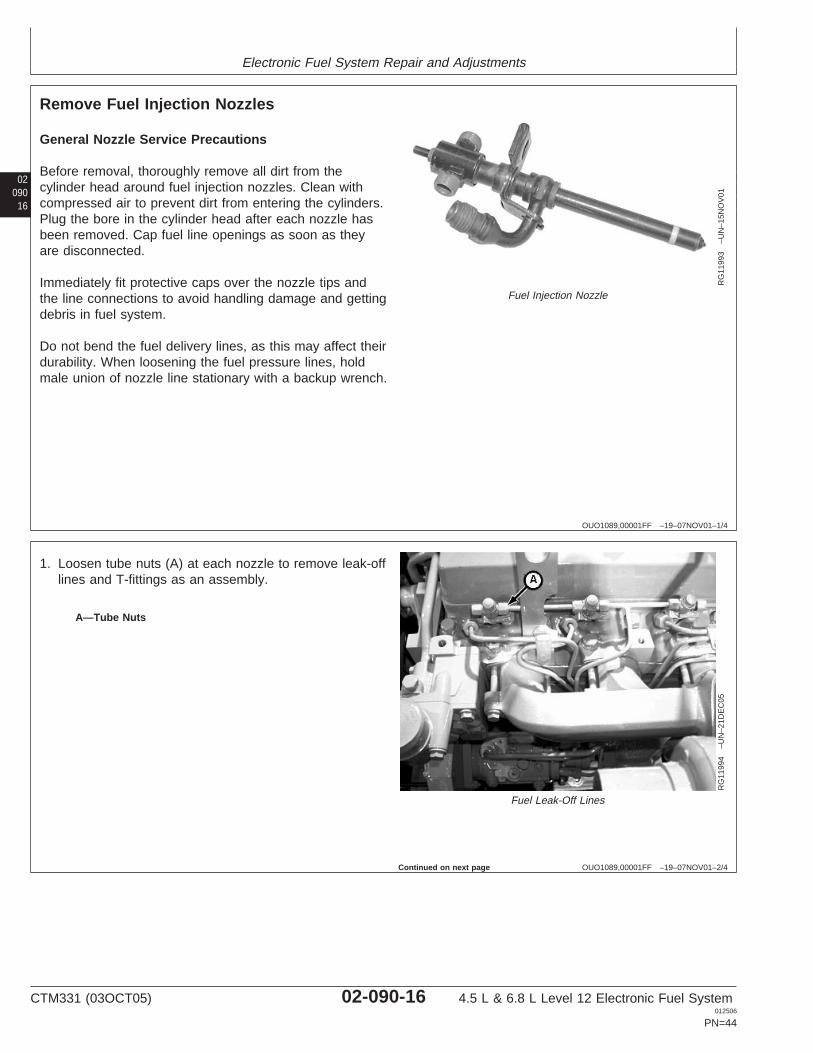
A—Tube Nuts
1. Loosen tube nuts (A) at each nozzle to remove leak-offlines and T-fittings as an assembly.
Continued on next page
CTM331 (03OCT05) 02-090-16 4.5 L & 6.8 L Level 12 Electronic Fuel System012506
PN=44
Electronic Fuel System Repair and Adjustments
0209017
OUO1089,00001FF –19–07NOV01–3/4
RG
1199
9–U
N–1
9NO
V01
Fuel Injection Line at Nozzle
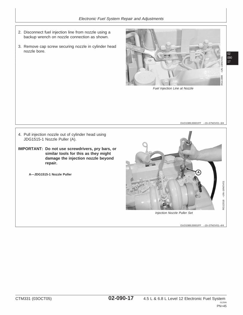
2. Disconnect fuel injection line from nozzle using abackup wrench on nozzle connection as shown.
3. Remove cap screw securing nozzle in cylinder headnozzle bore.
OUO1089,00001FF –19–07NOV01–4/4R
G12
018
–UN
–16N
OV
01
Injection Nozzle Puller Set
A—JDG1515-1 Nozzle Puller
4. Pull injection nozzle out of cylinder head usingJDG1515-1 Nozzle Puller (A).
IMPORTANT: Do not use screwdrivers, pry bars, orsimilar tools for this as they mightdamage the injection nozzle beyondrepair.
CTM331 (03OCT05) 02-090-17 4.5 L & 6.8 L Level 12 Electronic Fuel System012506
PN=45
Electronic Fuel System Repair and Adjustments
02090
18
RG,35,JW7596 –19–20NOV97–1/1
Clean Fuel Injection Nozzle Bore
RG
7743
–UN
–07N
OV
97
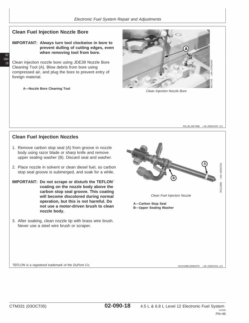
Clean Injection Nozzle BoreA—Nozzle Bore Cleaning Tool
IMPORTANT: Always turn tool clockwise in bore toprevent dulling of cutting edges, evenwhen removing tool from bore.
Clean injection nozzle bore using JDE39 Nozzle BoreCleaning Tool (A). Blow debris from bore usingcompressed air, and plug the bore to prevent entry offoreign material.
OUO1080,00001FD –19–15NOV01–1/1
Clean Fuel Injection Nozzles
RG
1199
5–U
N–1
5NO
V01
Clean Fuel Injection Nozzle
A—Carbon Stop SealB—Upper Sealing Washer
1. Remove carbon stop seal (A) from groove in nozzlebody using razor blade or sharp knife and removeupper sealing washer (B). Discard seal and washer.
2. Place nozzle in solvent or clean diesel fuel, so carbonstop seal groove is submerged, and soak for a while.
IMPORTANT: Do not scrape or disturb the TEFLON
coating on the nozzle body above thecarbon stop seal groove. This coatingwill become discolored during normaloperation, but this is not harmful. Donot use a motor-driven brush to cleannozzle body.
3. After soaking, clean nozzle tip with brass wire brush.Never use a steel wire brush or scraper.
TEFLON is a registered trademark of the DuPont Co.
CTM331 (03OCT05) 02-090-18 4.5 L & 6.8 L Level 12 Electronic Fuel System012506
PN=46
Electronic Fuel System Repair and Adjustments
0209019
OUO1089,0000200 –19–07NOV01–1/3
Fuel Injection Nozzle Test
X98
11–U
N–2
3AU
G88
High Pressure Fluid
L307
41–U
N–0
8AU
G89
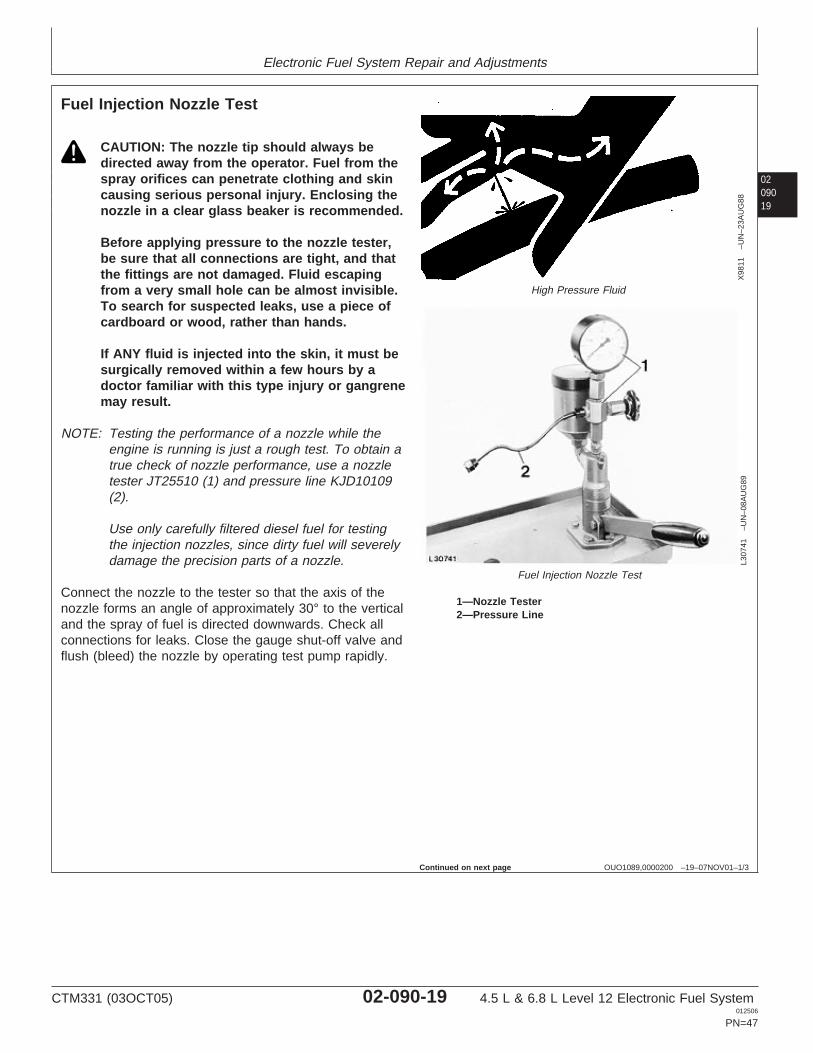
Fuel Injection Nozzle Test
1—Nozzle Tester2—Pressure Line
CAUTION: The nozzle tip should always bedirected away from the operator. Fuel from thespray orifices can penetrate clothing and skincausing serious personal injury. Enclosing thenozzle in a clear glass beaker is recommended.
Before applying pressure to the nozzle tester,be sure that all connections are tight, and thatthe fittings are not damaged. Fluid escapingfrom a very small hole can be almost invisible.To search for suspected leaks, use a piece ofcardboard or wood, rather than hands.
If ANY fluid is injected into the skin, it must besurgically removed within a few hours by adoctor familiar with this type injury or gangrenemay result.
NOTE: Testing the performance of a nozzle while theengine is running is just a rough test. To obtain atrue check of nozzle performance, use a nozzletester JT25510 (1) and pressure line KJD10109(2).
Use only carefully filtered diesel fuel for testingthe injection nozzles, since dirty fuel will severelydamage the precision parts of a nozzle.
Connect the nozzle to the tester so that the axis of thenozzle forms an angle of approximately 30° to the verticaland the spray of fuel is directed downwards. Check allconnections for leaks. Close the gauge shut-off valve andflush (bleed) the nozzle by operating test pump rapidly.
Continued on next page
CTM331 (03OCT05) 02-090-19 4.5 L & 6.8 L Level 12 Electronic Fuel System012506
PN=47
Electronic Fuel System Repair and Adjustments
02090
20
OUO1089,0000200 –19–07NOV01–2/3
Spray Pattern Test
Close gauge shut-off valve and operate the pump lever at60 strokes per minute. If the fuel injection nozzle isworking properly, the fuel should issue through all nozzleorifices in a fine, evenly shaped spray cone. This spraycone is inclined from the centerline of the nozzle body, butshould be distributed. For a better check, place a piece ofpaper or cardboard at a suitable distance below thenozzle and check the appearance of the damp circularspots made by the fuel. Deviations from the regular spraypattern or angle may be due to the complete or partialclogging of a nozzle orifice. In this case the fuel issues ina jet rather than in a fine spray.
Checking Valve Stem and Guide Wear
Connect fuel injection nozzle to the nozzle tester with thetip raised a little higher than its opposite end.Cover the tip and pump the tester to a pressure of10 300 kPa (103 bar) (1500 psi). Keep the pressureconstant and observe how much fuel leaks out of thenozzle return end. After the first drop has formed, countthe drops for 30 seconds and compare with specification.
Fuel Injection Nozzle—SpecificationNozzle—Return Leakage at10 300 kPa (103 bar) (1500 psi) 1 to 14 drops (maximum) within
30 seconds.............
Checking Valve Seat
Connect the nozzle to tester in horizontal position.Operate the pump lever rapidly to bleed the nozzle andallow the valve to seat. Dry the tip of the nozzlethoroughly. Now operate the pump lever slowly until theindicated pressure is approximately 2800 to 3500 kPa(28 to 35 bar) (400 to 500 psi) below opening pressure(see specification for opening pressure). Keep watchingthe nozzle. Under these conditions the fluid should notdrip out of the nozzle tip. However some weeping or lightmoisture on the tip is considered acceptable. Work thepump lever quickly several times in succession to makethe nozzle spray in the normal way. After the last stroke ofthe pump, observe again. If the nozzle is not quiteleakproof, disassemble for servicing.
CTM331 (03OCT05) 02-090-20 4.5 L & 6.8 L Level 12 Electronic Fuel System012506
PN=48
Continued on next page
Electronic Fuel System Repair and Adjustments
0209021
OUO1089,0000200 –19–07NOV01–3/3
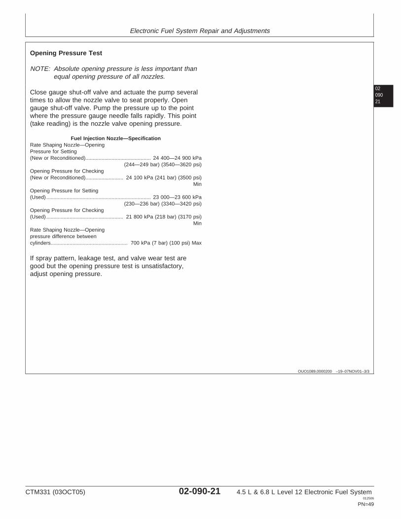
Opening Pressure Test
NOTE: Absolute opening pressure is less important thanequal opening pressure of all nozzles.
Close gauge shut-off valve and actuate the pump severaltimes to allow the nozzle valve to seat properly. Opengauge shut-off valve. Pump the pressure up to the pointwhere the pressure gauge needle falls rapidly. This point(take reading) is the nozzle valve opening pressure.
Fuel Injection Nozzle—SpecificationRate Shaping Nozzle—OpeningPressure for Setting(New or Reconditioned) 24 400—24 900 kPa
(244—249 bar) (3540—3620 psi).............................................
Opening Pressure for Checking(New or Reconditioned) 24 100 kPa (241 bar) (3500 psi)
Min..........................
Opening Pressure for Setting(Used) 23 000—23 600 kPa
(230—236 bar) (3340—3420 psi)........................................................................
Opening Pressure for Checking(Used) 21 800 kPa (218 bar) (3170 psi)
Min.....................................................
Rate Shaping Nozzle—Openingpressure difference betweencylinders 700 kPa (7 bar) (100 psi) Max.....................................................
If spray pattern, leakage test, and valve wear test aregood but the opening pressure test is unsatisfactory,adjust opening pressure.
CTM331 (03OCT05) 02-090-21 4.5 L & 6.8 L Level 12 Electronic Fuel System012506
PN=49
Electronic Fuel System Repair and Adjustments
02090
22
OUO1089,0000201 –19–07NOV01–1/1
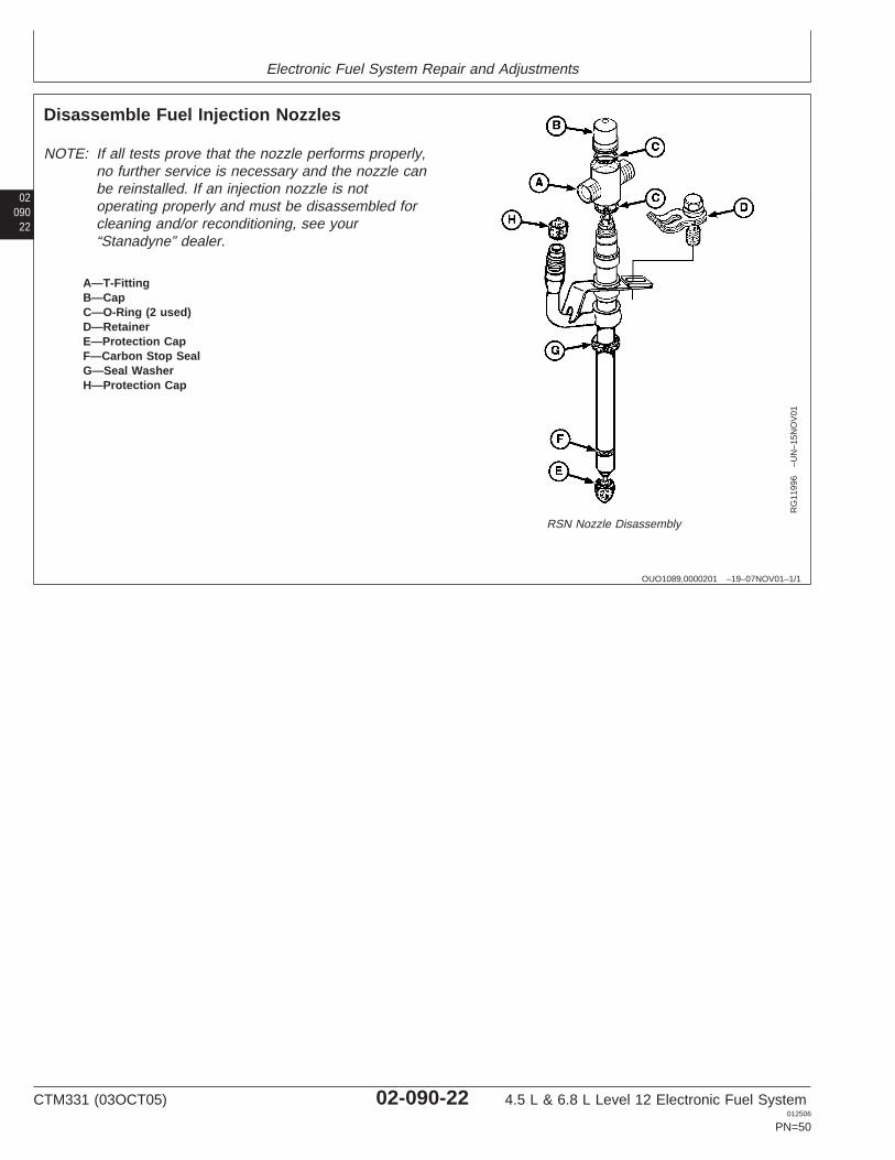
Disassemble Fuel Injection Nozzles
RG
1199
6–U
N–1
5NO
V01
RSN Nozzle Disassembly
A—T-FittingB—CapC—O-Ring (2 used)D—RetainerE—Protection CapF—Carbon Stop SealG—Seal WasherH—Protection Cap
NOTE: If all tests prove that the nozzle performs properly,no further service is necessary and the nozzle canbe reinstalled. If an injection nozzle is notoperating properly and must be disassembled forcleaning and/or reconditioning, see your“Stanadyne” dealer.
CTM331 (03OCT05) 02-090-22 4.5 L & 6.8 L Level 12 Electronic Fuel System012506
PN=50
Electronic Fuel System Repair and Adjustments
0209023
OUO1089,0000202 –19–07NOV01–1/2
Adjust Fuel Injection Nozzle
X98
11–U
N–2
3AU
G88
High Pressure Fluids
RG
1199
7–U
N–1
5NO
V01
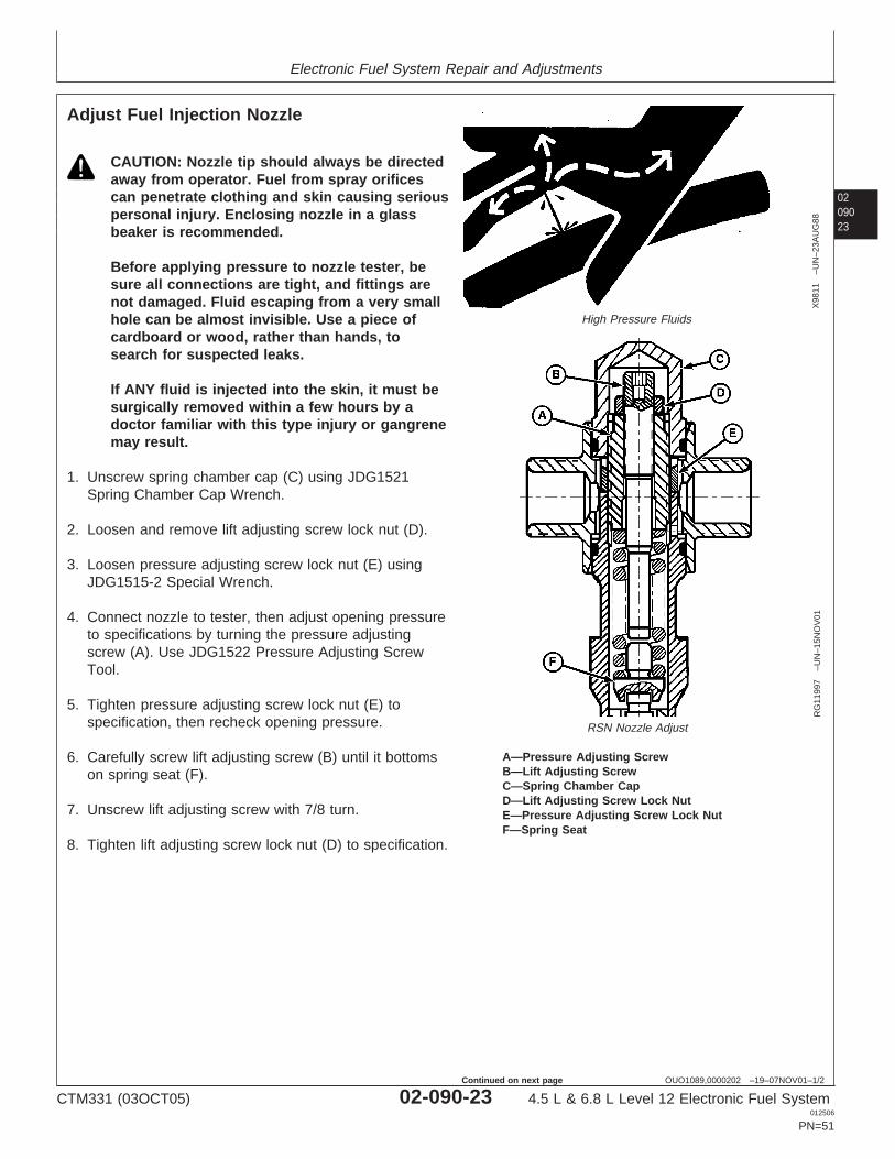
RSN Nozzle Adjust
A—Pressure Adjusting ScrewB—Lift Adjusting ScrewC—Spring Chamber CapD—Lift Adjusting Screw Lock NutE—Pressure Adjusting Screw Lock NutF—Spring Seat
CAUTION: Nozzle tip should always be directedaway from operator. Fuel from spray orificescan penetrate clothing and skin causing seriouspersonal injury. Enclosing nozzle in a glassbeaker is recommended.
Before applying pressure to nozzle tester, besure all connections are tight, and fittings arenot damaged. Fluid escaping from a very smallhole can be almost invisible. Use a piece ofcardboard or wood, rather than hands, tosearch for suspected leaks.
If ANY fluid is injected into the skin, it must besurgically removed within a few hours by adoctor familiar with this type injury or gangrenemay result.
1. Unscrew spring chamber cap (C) using JDG1521Spring Chamber Cap Wrench.
2. Loosen and remove lift adjusting screw lock nut (D).
3. Loosen pressure adjusting screw lock nut (E) usingJDG1515-2 Special Wrench.
4. Connect nozzle to tester, then adjust opening pressureto specifications by turning the pressure adjustingscrew (A). Use JDG1522 Pressure Adjusting ScrewTool.
5. Tighten pressure adjusting screw lock nut (E) tospecification, then recheck opening pressure.
6. Carefully screw lift adjusting screw (B) until it bottomson spring seat (F).
7. Unscrew lift adjusting screw with 7/8 turn.
8. Tighten lift adjusting screw lock nut (D) to specification.
CTM331 (03OCT05) 02-090-23 4.5 L & 6.8 L Level 12 Electronic Fuel System012506
PN=51
Continued on next page
Electronic Fuel System Repair and Adjustments
02090
24
OUO1089,0000202 –19–07NOV01–2/2
9. Recheck opening pressure.
Fuel Injection Nozzle—SpecificationPressure Adjusting Screw LockNut—Torque 10 N•m (7 lb-ft)......................................................................Lift Adjusting Screw Lock Nut—Torque 5 N•m (3.5 lb-ft)..............................................................................
RG,35,JW7586 –19–20NOV97–1/1
Install Seals on Fuel Injection Nozzle
RG
9096
–UN
–27M
AR
98
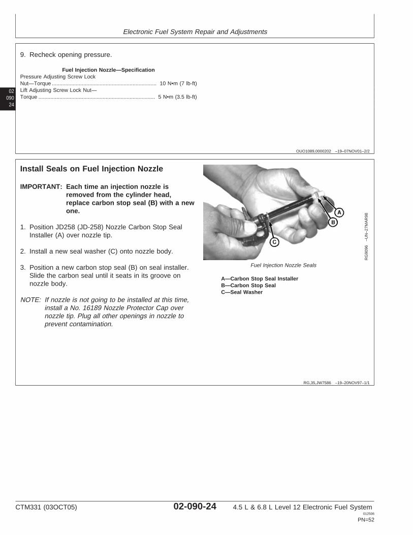
Fuel Injection Nozzle Seals
A—Carbon Stop Seal InstallerB—Carbon Stop SealC—Seal Washer
IMPORTANT: Each time an injection nozzle isremoved from the cylinder head,replace carbon stop seal (B) with a newone.
1. Position JD258 (JD-258) Nozzle Carbon Stop SealInstaller (A) over nozzle tip.
2. Install a new seal washer (C) onto nozzle body.
3. Position a new carbon stop seal (B) on seal installer.Slide the carbon seal until it seats in its groove onnozzle body.
NOTE: If nozzle is not going to be installed at this time,install a No. 16189 Nozzle Protector Cap overnozzle tip. Plug all other openings in nozzle toprevent contamination.
CTM331 (03OCT05) 02-090-24 4.5 L & 6.8 L Level 12 Electronic Fuel System012506
PN=52
Electronic Fuel System Repair and Adjustments
0209025
OUO1080,0000200 –19–16NOV01–1/2
Install Fuel Injection Nozzles
RG
1199
8–U
N–1
9NO
V01
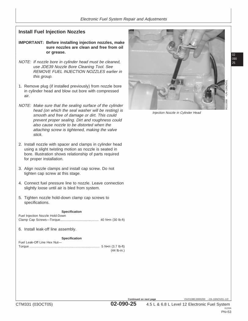
Injection Nozzle in Cylinder Head
IMPORTANT: Before installing injection nozzles, makesure nozzles are clean and free from oilor grease.
NOTE: If nozzle bore in cylinder head must be cleaned,use JDE39 Nozzle Bore Cleaning Tool. SeeREMOVE FUEL INJECTION NOZZLES earlier inthis group.
1. Remove plug (if installed previously) from nozzle borein cylinder head and blow out bore with compressedair.
NOTE: Make sure that the sealing surface of the cylinderhead (on which the seal washer will be resting) issmooth and free of damage or dirt. This couldprevent proper sealing. Dirt and roughness couldalso cause nozzle to be distorted when theattaching screw is tightened, making the valvestick.
2. Install nozzle with spacer and clamps in cylinder headusing a slight twisting motion as nozzle is seated inbore. Illustration shows relationship of parts requiredfor proper installation.
3. Align nozzle clamps and install cap screw. Do nottighten cap screw at this stage.
4. Connect fuel pressure line to nozzle. Leave connectionslightly loose until air is bled from system.
5. Tighten nozzle hold-down clamp cap screws tospecifications.
SpecificationFuel Injection Nozzle Hold-DownClamp Cap Screws—Torque 40 N•m (30 lb-ft)...........................................
6. Install leak-off line assembly.
SpecificationFuel Leak-Off Line Hex Nut—Torque 5 N•m (3.7 lb-ft)
(44 lb-in.)..............................................................................
CTM331 (03OCT05) 02-090-25 4.5 L & 6.8 L Level 12 Electronic Fuel System012506
PN=53
Continued on next page
Electronic Fuel System Repair and Adjustments
02090
26
OUO1080,0000200 –19–16NOV01–2/2
RG
1199
9–U
N–1
9NO
V01
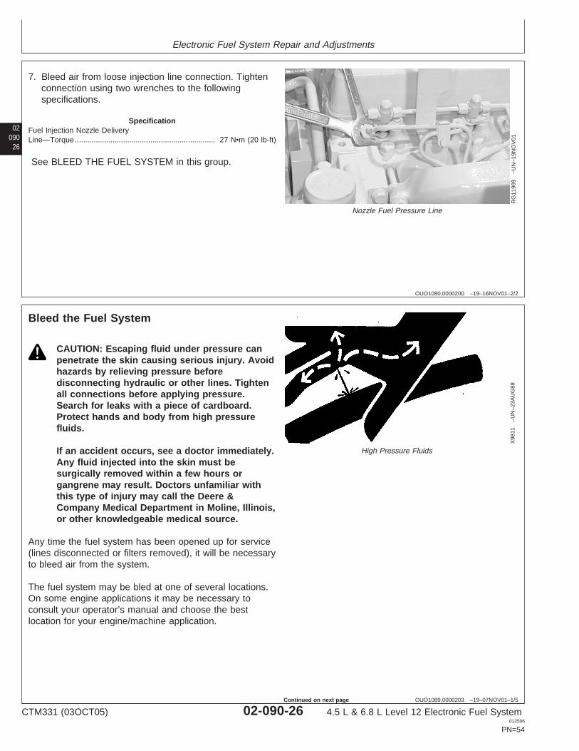
Nozzle Fuel Pressure Line
7. Bleed air from loose injection line connection. Tightenconnection using two wrenches to the followingspecifications.
SpecificationFuel Injection Nozzle DeliveryLine—Torque 27 N•m (20 lb-ft)...................................................................
See BLEED THE FUEL SYSTEM in this group.
OUO1089,0000203 –19–07NOV01–1/5
Bleed the Fuel System
X98
11–U
N–2
3AU
G88
High Pressure Fluids
CAUTION: Escaping fluid under pressure canpenetrate the skin causing serious injury. Avoidhazards by relieving pressure beforedisconnecting hydraulic or other lines. Tightenall connections before applying pressure.Search for leaks with a piece of cardboard.Protect hands and body from high pressurefluids.
If an accident occurs, see a doctor immediately.Any fluid injected into the skin must besurgically removed within a few hours organgrene may result. Doctors unfamiliar withthis type of injury may call the Deere &Company Medical Department in Moline, Illinois,or other knowledgeable medical source.
Any time the fuel system has been opened up for service(lines disconnected or filters removed), it will be necessaryto bleed air from the system.
The fuel system may be bled at one of several locations.On some engine applications it may be necessary toconsult your operator’s manual and choose the bestlocation for your engine/machine application.
CTM331 (03OCT05) 02-090-26 4.5 L & 6.8 L Level 12 Electronic Fuel System012506
PN=54
Continued on next page
Electronic Fuel System Repair and Adjustments
0209027
OUO1089,0000203 –19–07NOV01–2/5
RG
1180
5–U
N–2
5OC
T01
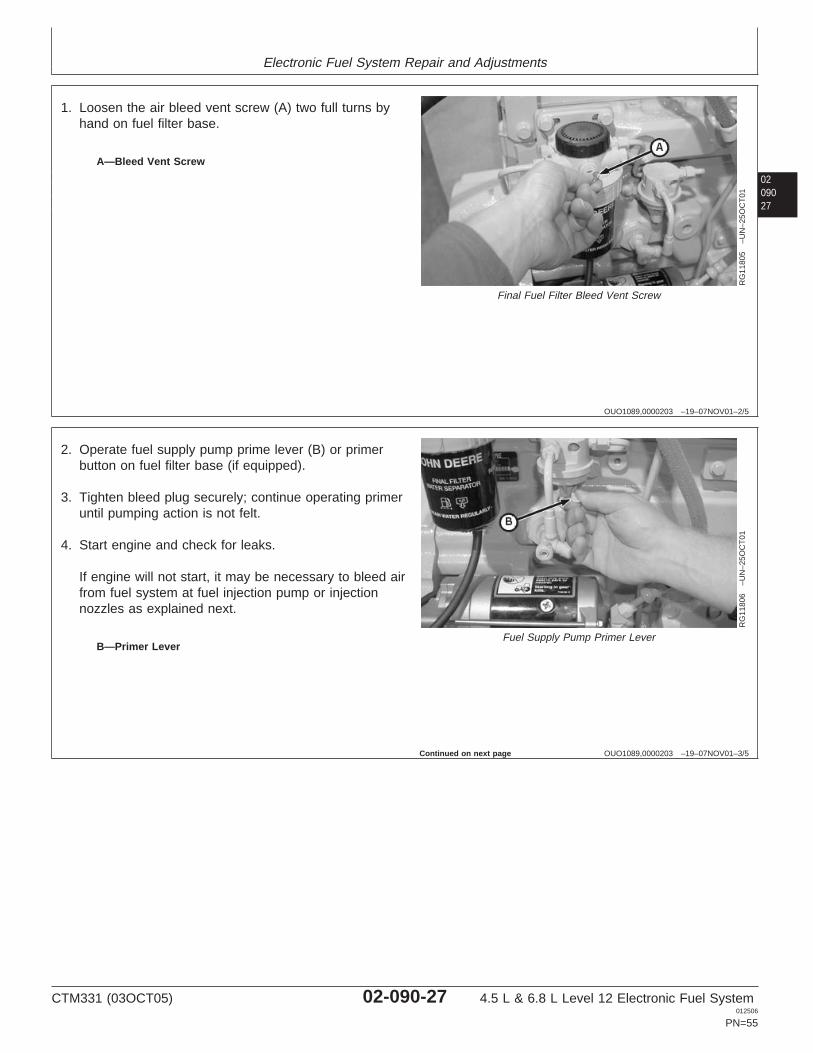
Final Fuel Filter Bleed Vent Screw
A—Bleed Vent Screw
1. Loosen the air bleed vent screw (A) two full turns byhand on fuel filter base.
OUO1089,0000203 –19–07NOV01–3/5
RG
1180
6–U
N–2
5OC
T01
Fuel Supply Pump Primer LeverB—Primer Lever
2. Operate fuel supply pump prime lever (B) or primerbutton on fuel filter base (if equipped).
3. Tighten bleed plug securely; continue operating primeruntil pumping action is not felt.
4. Start engine and check for leaks.
If engine will not start, it may be necessary to bleed airfrom fuel system at fuel injection pump or injectionnozzles as explained next.
Continued on next page
CTM331 (03OCT05) 02-090-27 4.5 L & 6.8 L Level 12 Electronic Fuel System012506
PN=55
Electronic Fuel System Repair and Adjustments
02090
28
OUO1089,0000203 –19–07NOV01–4/5
RG
1180
7–U
N–2
5OC
T01
Fuel Injection Pump Return Line
A—Fuel Return Line
At Fuel Injection Pump
1. Loosen fuel return line (A) at fuel injection pump.
2. Operate fuel supply pump primer lever or primer buttonon fuel filter base (if equipped).
3. As soon as fuel flow is free from air bubbles, tightenfuel return line to specifications. Primer lever isspring-loaded and will return to normal position.
SpecificationFuel Injection Pump ReturnLine—Torque 27 N•m (20 lb-ft)...................................................................
OUO1089,0000203 –19–07NOV01–5/5
RG
1180
8–U
N–2
5OC
T01
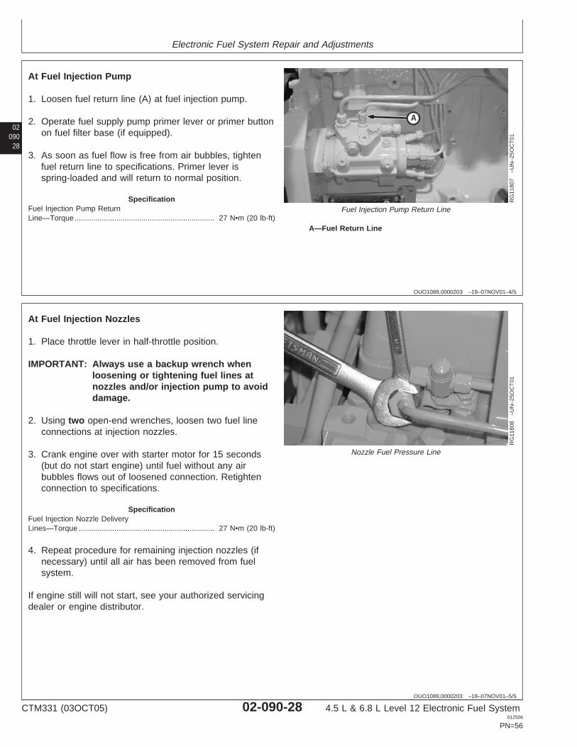
Nozzle Fuel Pressure Line
At Fuel Injection Nozzles
1. Place throttle lever in half-throttle position.
IMPORTANT: Always use a backup wrench whenloosening or tightening fuel lines atnozzles and/or injection pump to avoiddamage.
2. Using two open-end wrenches, loosen two fuel lineconnections at injection nozzles.
3. Crank engine over with starter motor for 15 seconds(but do not start engine) until fuel without any airbubbles flows out of loosened connection. Retightenconnection to specifications.
SpecificationFuel Injection Nozzle DeliveryLines—Torque 27 N•m (20 lb-ft).................................................................
4. Repeat procedure for remaining injection nozzles (ifnecessary) until all air has been removed from fuelsystem.
If engine still will not start, see your authorized servicingdealer or engine distributor.
CTM331 (03OCT05) 02-090-28 4.5 L & 6.8 L Level 12 Electronic Fuel System012506
PN=56
Group 110Electrical Engine Control Repair and Adjustment
021101
OUO1080,0000201 –19–16NOV01–1/1
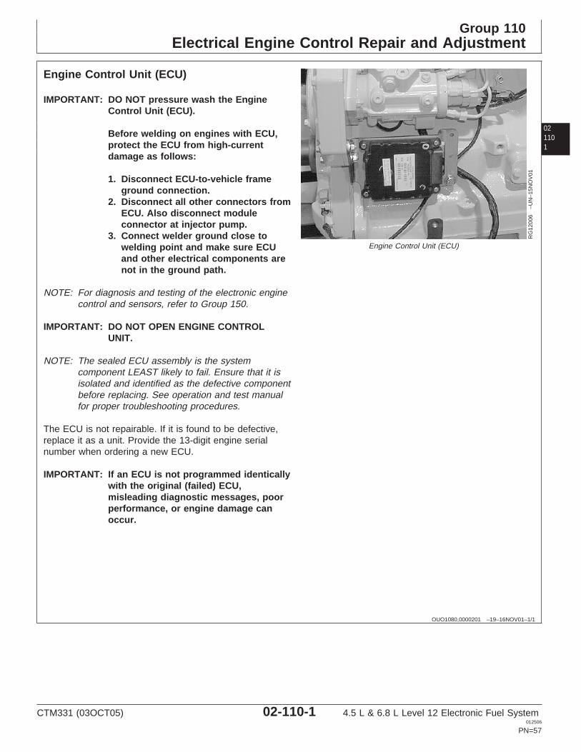
Engine Control Unit (ECU)
RG
1200
6–U
N–1
5NO
V01
Engine Control Unit (ECU)
IMPORTANT: DO NOT pressure wash the EngineControl Unit (ECU).
Before welding on engines with ECU,protect the ECU from high-currentdamage as follows:
1. Disconnect ECU-to-vehicle frameground connection.
2. Disconnect all other connectors fromECU. Also disconnect moduleconnector at injector pump.
3. Connect welder ground close towelding point and make sure ECUand other electrical components arenot in the ground path.
NOTE: For diagnosis and testing of the electronic enginecontrol and sensors, refer to Group 150.
IMPORTANT: DO NOT OPEN ENGINE CONTROLUNIT.
NOTE: The sealed ECU assembly is the systemcomponent LEAST likely to fail. Ensure that it isisolated and identified as the defective componentbefore replacing. See operation and test manualfor proper troubleshooting procedures.
The ECU is not repairable. If it is found to be defective,replace it as a unit. Provide the 13-digit engine serialnumber when ordering a new ECU.
IMPORTANT: If an ECU is not programmed identicallywith the original (failed) ECU,misleading diagnostic messages, poorperformance, or engine damage canoccur.
CTM331 (03OCT05) 02-110-1 4.5 L & 6.8 L Level 12 Electronic Fuel System012506
PN=57
Electrical Engine Control Repair and Adjustment
02110
2
OUO1080,0000202 –19–16NOV01–1/1
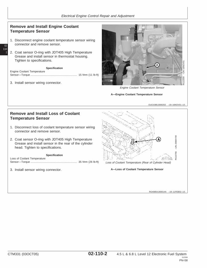
Remove and Install Engine CoolantTemperature Sensor
RG
1200
9–U
N–1
6NO
V01
Engine Coolant Temperature Sensor
A—Engine Coolant Temperature Sensor
1. Disconnect engine coolant temperature sensor wiringconnector and remove sensor.
2. Coat sensor O-ring with JDT405 High TemperatureGrease and install sensor in thermostat housing.Tighten to specifications.
SpecificationEngine Coolant TemperatureSensor—Torque 15 N•m (11 lb-ft)..............................................................
3. Install sensor wiring connector.
RG40854,000014A –19–11FEB02–1/1
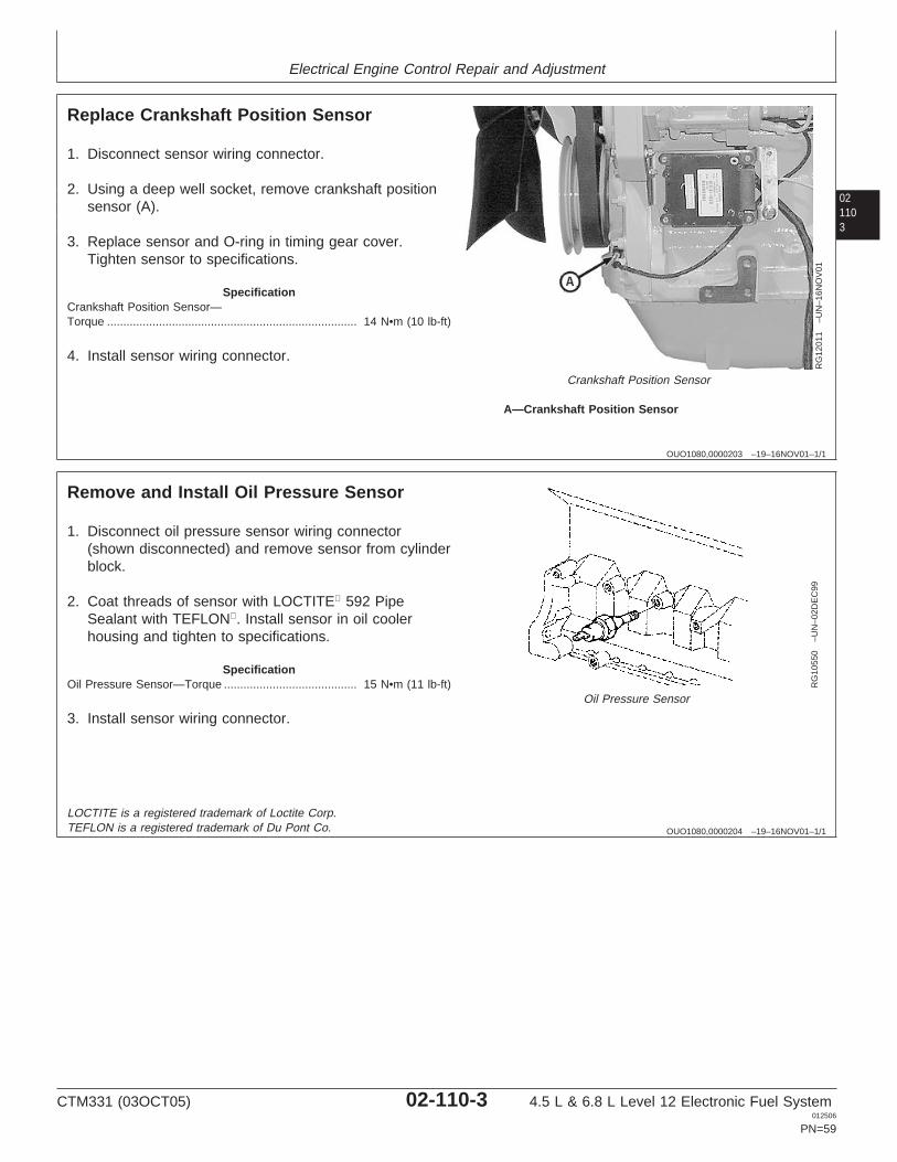
Remove and Install Loss of CoolantTemperature Sensor
RG
1076
6–U
N–2
6MA
Y00
Loss of Coolant Temperature (Rear of Cylinder Head)
A—Loss of Coolant Temperature Sensor
1. Disconnect loss of coolant temperature sensor wiringconnector and remove sensor.
2. Coat sensor O-ring with JDT405 High TemperatureGrease and install sensor in the rear of the cylinderhead. Tighten to specifications.
SpecificationLoss of Coolant TemperatureSensor—Torque 35 N•m (26 lb-ft)..............................................................
3. Install sensor wiring connector.
CTM331 (03OCT05) 02-110-2 4.5 L & 6.8 L Level 12 Electronic Fuel System012506
PN=58
Electrical Engine Control Repair and Adjustment
021103
OUO1080,0000203 –19–16NOV01–1/1
Replace Crankshaft Position Sensor
RG
1201
1–U
N–1
6NO
V01
Crankshaft Position Sensor
A—Crankshaft Position Sensor
1. Disconnect sensor wiring connector.
2. Using a deep well socket, remove crankshaft positionsensor (A).
3. Replace sensor and O-ring in timing gear cover.Tighten sensor to specifications.
SpecificationCrankshaft Position Sensor—Torque 14 N•m (10 lb-ft).............................................................................
4. Install sensor wiring connector.
OUO1080,0000204 –19–16NOV01–1/1
Remove and Install Oil Pressure Sensor
RG
1055
0–U
N–0
2DE
C99
Oil Pressure Sensor
1. Disconnect oil pressure sensor wiring connector(shown disconnected) and remove sensor from cylinderblock.
2. Coat threads of sensor with LOCTITE 592 PipeSealant with TEFLON. Install sensor in oil coolerhousing and tighten to specifications.
SpecificationOil Pressure Sensor—Torque 15 N•m (11 lb-ft).........................................
3. Install sensor wiring connector.
LOCTITE is a registered trademark of Loctite Corp.TEFLON is a registered trademark of Du Pont Co.
CTM331 (03OCT05) 02-110-3 4.5 L & 6.8 L Level 12 Electronic Fuel System012506
PN=59
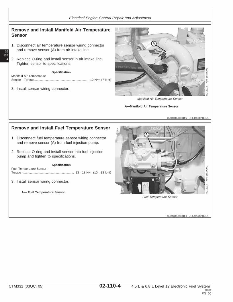
Electrical Engine Control Repair and Adjustment
02110
4
OUO1080,00001F5 –19–09NOV01–1/1
Remove and Install Manifold Air TemperatureSensor
RG
1201
3–U
N–1
6NO
V01
Manifold Air Temperature Sensor
A—Manifold Air Temperature Sensor
1. Disconnect air temperature sensor wiring connectorand remove sensor (A) from air intake line.
2. Replace O-ring and install sensor in air intake line.Tighten sensor to specifications.
SpecificationManifold Air TemperatureSensor—Torque 10 N•m (7 lb-ft)................................................................
3. Install sensor wiring connector.
OUO1080,00001F6 –19–12NOV01–1/1
Remove and Install Fuel Temperature Sensor
RG
1201
4–U
N–1
6NO
V01
Fuel Temperature Sensor
A— Fuel Temperature Sensor
1. Disconnect fuel temperature sensor wiring connectorand remove sensor (A) from fuel injection pump.
2. Replace O-ring and install sensor into fuel injectionpump and tighten to specifications.
SpecificationFuel Temperature Sensor—Torque 13—18 N•m (10—13 lb-ft)..............................................................
3. Install sensor wiring connector.
CTM331 (03OCT05) 02-110-4 4.5 L & 6.8 L Level 12 Electronic Fuel System012506
PN=60
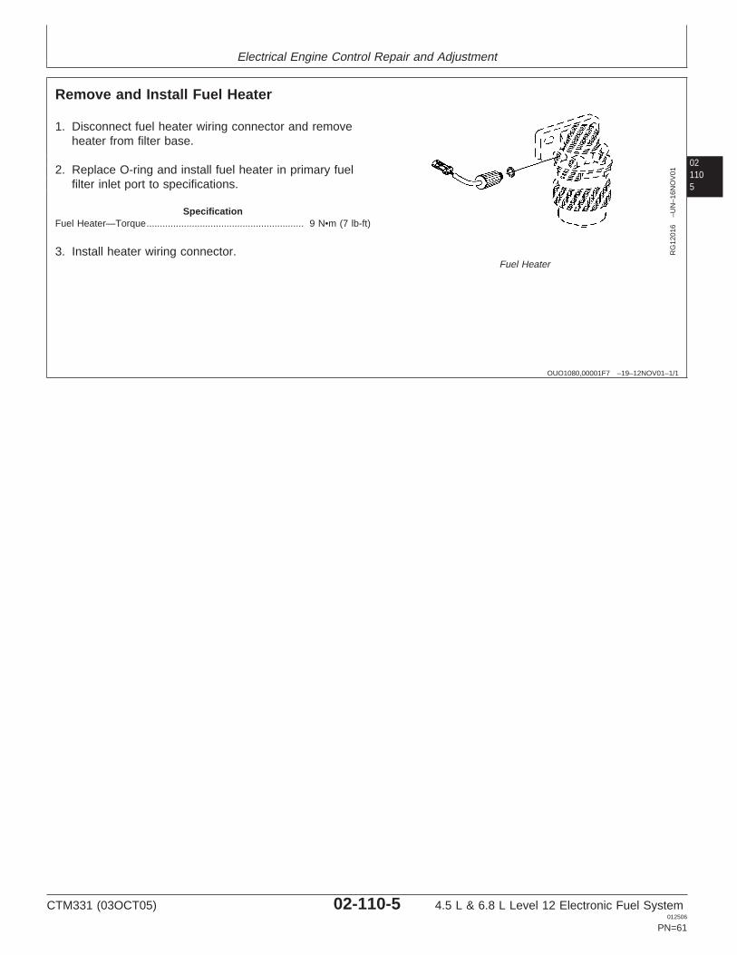
Electrical Engine Control Repair and Adjustment
021105
OUO1080,00001F7 –19–12NOV01–1/1
Remove and Install Fuel Heater
RG
1201
6–U
N–1
6NO
V01
Fuel Heater
1. Disconnect fuel heater wiring connector and removeheater from filter base.
2. Replace O-ring and install fuel heater in primary fuelfilter inlet port to specifications.
SpecificationFuel Heater—Torque 9 N•m (7 lb-ft)...........................................................
3. Install heater wiring connector.
CTM331 (03OCT05) 02-110-5 4.5 L & 6.8 L Level 12 Electronic Fuel System012506
PN=61
Electrical Engine Control Repair and Adjustment
02110
6
RG,RG34710,1328 –19–23OCT97–1/1
Connectors
Connectors are devices that provide for assembly anddisassembly of systems. Connectors should always beserviced using tools designed for that type of connector. Agood crimp is important to mechanical and electricalsoundness. Repaired connectors should be physicallytested by pulling to be sure the contact is firmly attachedto the conductor.
IMPORTANT: If for some reason the connectors arenot connected, such as when the fuelinjection pump is removed, it isimportant to protect the connectorsfrom debris.
Refer to the procedures which follow for repair of varioustypes of connectors.
RG,RG34710,1335 –19–23OCT97–1/1
Use Electrical Insulating Compound
Apply AT66865 Compound directly to the terminalsbetween the wire seal and connector body. This providesa moisture barrier, especially in wet and humid conditions.
CTM331 (03OCT05) 02-110-6 4.5 L & 6.8 L Level 12 Electronic Fuel System012506
PN=62
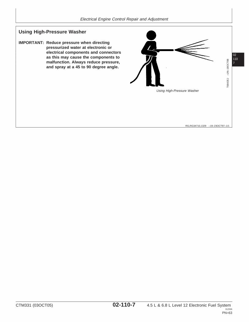
Electrical Engine Control Repair and Adjustment
021107
RG,RG34710,1329 –19–23OCT97–1/1
Using High-Pressure Washer
T66
42E
J–U
N–1
8OC
T88
Using High-Pressure Washer
IMPORTANT: Reduce pressure when directingpressurized water at electronic orelectrical components and connectorsas this may cause the components tomalfunction. Always reduce pressure,and spray at a 45 to 90 degree angle.
CTM331 (03OCT05) 02-110-7 4.5 L & 6.8 L Level 12 Electronic Fuel System012506
PN=63
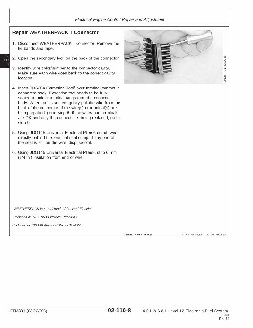
Electrical Engine Control Repair and Adjustment
02110
8
AG,OUOD008,296 –19–06MAR02–1/4
Repair WEATHERPACK Connector
TS
0128
–UN
–23A
UG
88
1. Disconnect WEATHERPACK connector. Remove thetie bands and tape.
2. Open the secondary lock on the back of the connector.
3. Identify wire color/number to the connector cavity.Make sure each wire goes back to the correct cavitylocation.
4. Insert JDG364 Extraction Tool1 over terminal contact inconnector body. Extraction tool needs to be fullyseated to unlock terminal tangs from the connectorbody. When tool is seated, gently pull the wire from theback of the connector. If the wire(s) or terminal(s) arebeing repaired, go to step 5. If the wires and terminalsare OK and only the connector is being replaced, go tostep 9.
5. Using JDG145 Universal Electrical Pliers2, cut off wiredirectly behind the terminal seal crimp. If any part ofthe seal is still on the wire, dispose of it.
6. Using JDG145 Universal Electrical Pliers2, strip 6 mm(1/4 in.) insulation from end of wire.
WEATHERPACK is a trademark of Packard Electric
1 Included in JT07195B Electrical Repair Kit
2Included in JDG155 Electrical Repair Tool Kit
Continued on next page
CTM331 (03OCT05) 02-110-8 4.5 L & 6.8 L Level 12 Electronic Fuel System012506
PN=64
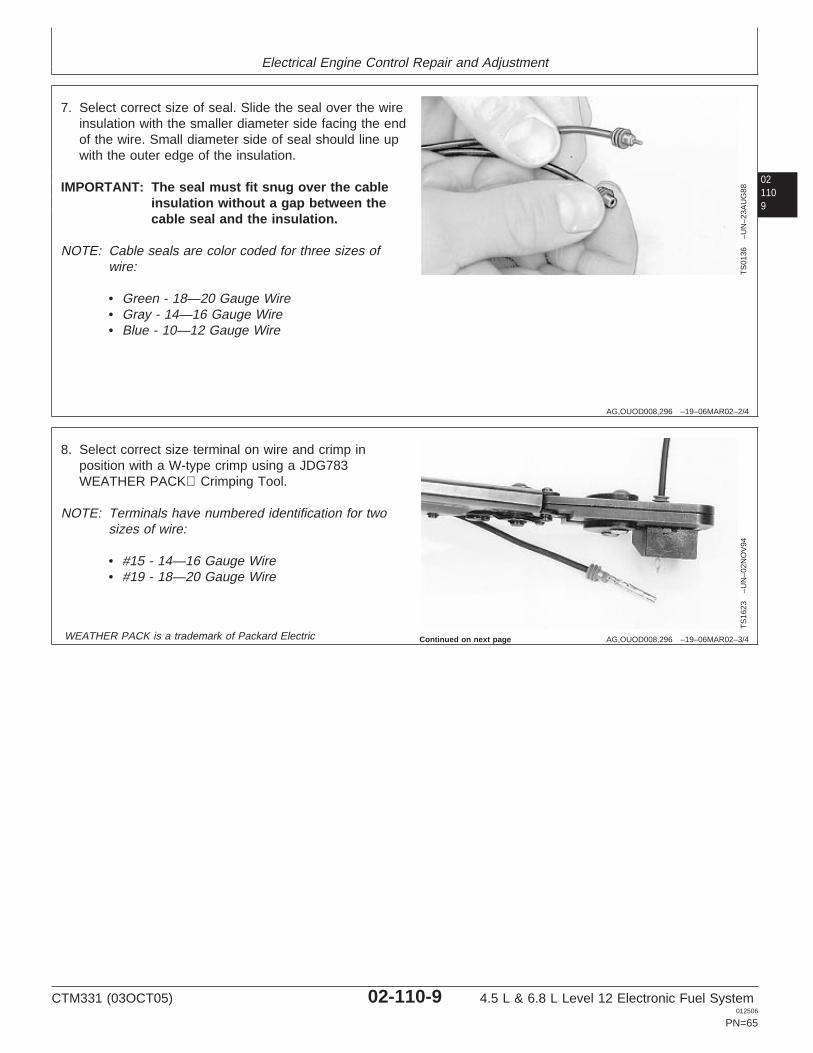
Electrical Engine Control Repair and Adjustment
021109
AG,OUOD008,296 –19–06MAR02–2/4
TS
0136
–UN
–23A
UG
88
7. Select correct size of seal. Slide the seal over the wireinsulation with the smaller diameter side facing the endof the wire. Small diameter side of seal should line upwith the outer edge of the insulation.
IMPORTANT: The seal must fit snug over the cableinsulation without a gap between thecable seal and the insulation.
NOTE: Cable seals are color coded for three sizes ofwire:
• Green - 18—20 Gauge Wire• Gray - 14—16 Gauge Wire• Blue - 10—12 Gauge Wire
AG,OUOD008,296 –19–06MAR02–3/4
TS
1623
–UN
–02N
OV
94
8. Select correct size terminal on wire and crimp inposition with a W-type crimp using a JDG783WEATHER PACK Crimping Tool.
NOTE: Terminals have numbered identification for twosizes of wire:
• #15 - 14—16 Gauge Wire• #19 - 18—20 Gauge Wire
WEATHER PACK is a trademark of Packard Electric Continued on next page
CTM331 (03OCT05) 02-110-9 4.5 L & 6.8 L Level 12 Electronic Fuel System012506
PN=65
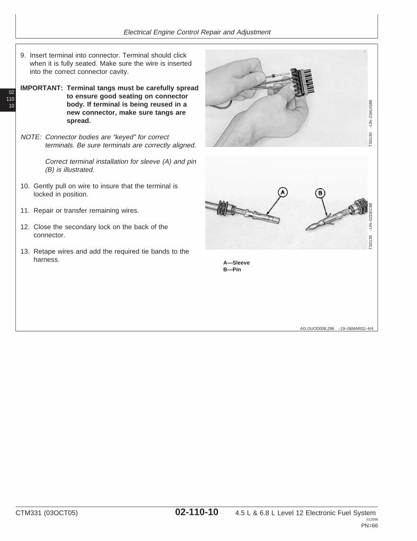
Electrical Engine Control Repair and Adjustment
02110
10
AG,OUOD008,296 –19–06MAR02–4/4
TS
0130
–UN
–23A
UG
88T
S01
39–U
N–0
2DE
C88
A—SleeveB—Pin
9. Insert terminal into connector. Terminal should clickwhen it is fully seated. Make sure the wire is insertedinto the correct connector cavity.
IMPORTANT: Terminal tangs must be carefully spreadto ensure good seating on connectorbody. If terminal is being reused in anew connector, make sure tangs arespread.
NOTE: Connector bodies are “keyed” for correctterminals. Be sure terminals are correctly aligned.
Correct terminal installation for sleeve (A) and pin(B) is illustrated.
10. Gently pull on wire to insure that the terminal islocked in position.
11. Repair or transfer remaining wires.
12. Close the secondary lock on the back of theconnector.
13. Retape wires and add the required tie bands to theharness.
CTM331 (03OCT05) 02-110-10 4.5 L & 6.8 L Level 12 Electronic Fuel System012506
PN=66
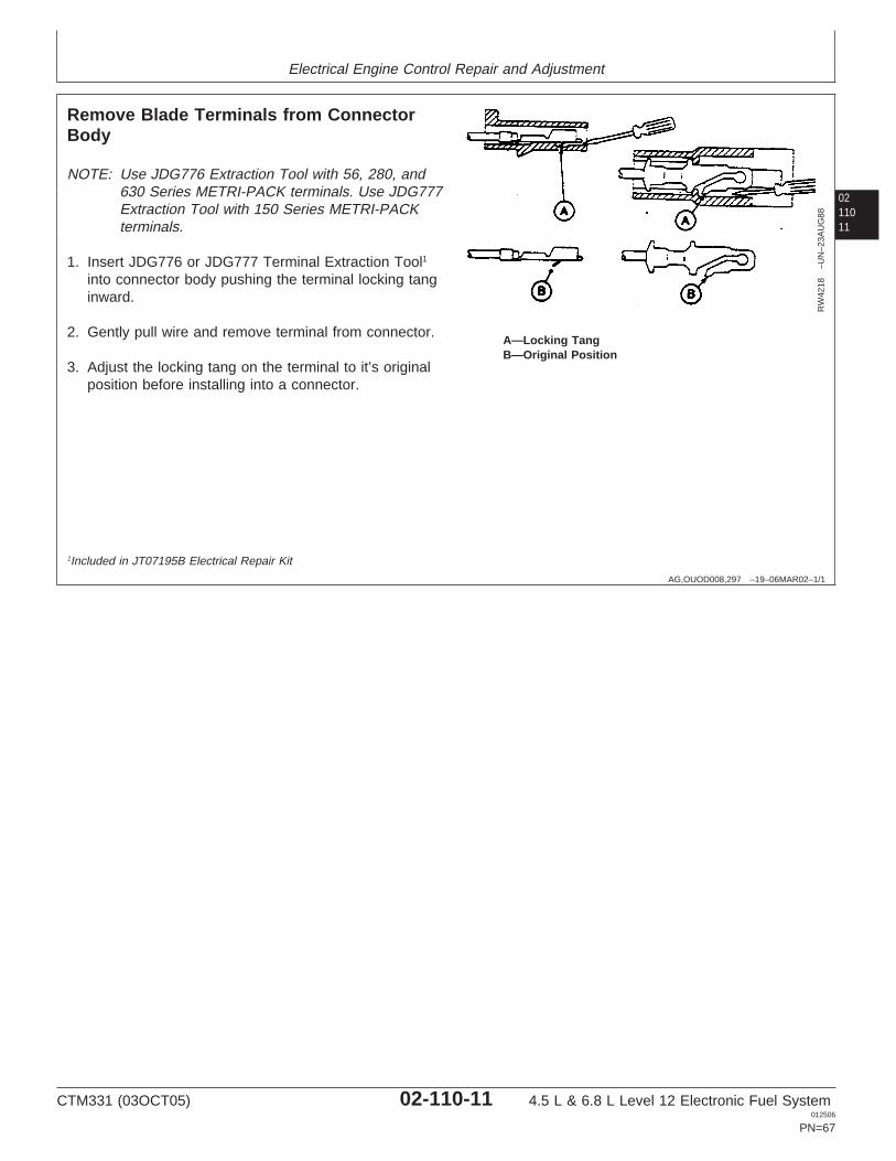
Electrical Engine Control Repair and Adjustment
0211011
AG,OUOD008,297 –19–06MAR02–1/1
Remove Blade Terminals from ConnectorBody
RW
4218
–UN
–23A
UG
88
A—Locking TangB—Original Position
NOTE: Use JDG776 Extraction Tool with 56, 280, and630 Series METRI-PACK terminals. Use JDG777Extraction Tool with 150 Series METRI-PACKterminals.
1. Insert JDG776 or JDG777 Terminal Extraction Tool1
into connector body pushing the terminal locking tanginward.
2. Gently pull wire and remove terminal from connector.
3. Adjust the locking tang on the terminal to it’s originalposition before installing into a connector.
1Included in JT07195B Electrical Repair Kit
CTM331 (03OCT05) 02-110-11 4.5 L & 6.8 L Level 12 Electronic Fuel System012506
PN=67
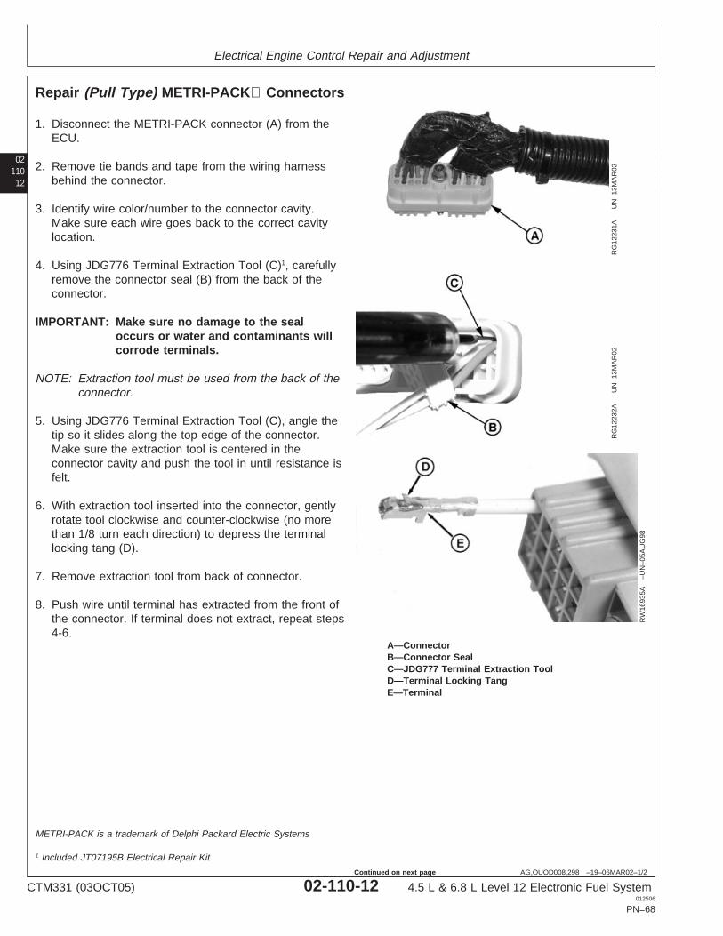
Electrical Engine Control Repair and Adjustment
02110
12
AG,OUOD008,298 –19–06MAR02–1/2
Repair (Pull Type) METRI-PACK Connectors
RG
1223
1A–U
N–1
3MA
R02
RG
1223
2A–U
N–1
3MA
R02
RW
1693
5A–U
N–0
5AU
G98
A—ConnectorB—Connector SealC—JDG777 Terminal Extraction ToolD—Terminal Locking TangE—Terminal
1. Disconnect the METRI-PACK connector (A) from theECU.
2. Remove tie bands and tape from the wiring harnessbehind the connector.
3. Identify wire color/number to the connector cavity.Make sure each wire goes back to the correct cavitylocation.
4. Using JDG776 Terminal Extraction Tool (C)1, carefullyremove the connector seal (B) from the back of theconnector.
IMPORTANT: Make sure no damage to the sealoccurs or water and contaminants willcorrode terminals.
NOTE: Extraction tool must be used from the back of theconnector.
5. Using JDG776 Terminal Extraction Tool (C), angle thetip so it slides along the top edge of the connector.Make sure the extraction tool is centered in theconnector cavity and push the tool in until resistance isfelt.
6. With extraction tool inserted into the connector, gentlyrotate tool clockwise and counter-clockwise (no morethan 1/8 turn each direction) to depress the terminallocking tang (D).
7. Remove extraction tool from back of connector.
8. Push wire until terminal has extracted from the front ofthe connector. If terminal does not extract, repeat steps4-6.
METRI-PACK is a trademark of Delphi Packard Electric Systems
1 Included JT07195B Electrical Repair Kit
CTM331 (03OCT05) 02-110-12 4.5 L & 6.8 L Level 12 Electronic Fuel System012506
PN=68
Continued on next page
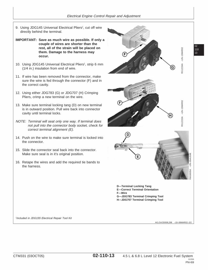
Electrical Engine Control Repair and Adjustment
0211013
AG,OUOD008,298 –19–06MAR02–2/2
RG
1223
4A–U
N–1
3MA
R02
RG
1223
3A–U
N–1
3MA
R02
RW
1693
5A–U
N–0
5AU
G98
D—Terminal Locking TangE—Correct Terminal OrientationF—WireG—JDG783 Terminal Crimping ToolH—JDG707 Terminal Crimping Tool
9. Using JDG145 Universal Electrical Pliers1, cut off wiredirectly behind the terminal.
IMPORTANT: Save as much wire as possible. If only acouple of wires are shorter than therest, all of the strain will be placed onthem. Damage to the harness mayoccur.
10. Using JDG145 Universal Electrical Pliers1, strip 6 mm(1/4 in.) insulation from end of wire.
11. If wire has been removed from the connector, makesure the wire is fed through the connector (F) and inthe correct cavity.
12. Using either JDG783 (G) or JDG707 (H) CrimpingPliers, crimp a new terminal on the wire.
13. Make sure terminal locking tang (D) on new terminalis in outward position. Pull wire back into connectorcavity until terminal locks.
NOTE: Terminal will seat only one way. If terminal doesnot pull into the connector body socket, check forcorrect terminal alignment (E).
14. Push on the wire to make sure terminal is locked intothe connector.
15. Slide the connector seal back into the connector.Make sure seal is in it’s original position.
16. Retape the wires and add the required tie bands tothe harness.
1Included in JDG155 Electrical Repair Tool Kit
CTM331 (03OCT05) 02-110-13 4.5 L & 6.8 L Level 12 Electronic Fuel System012506
PN=69
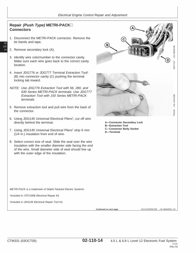
Electrical Engine Control Repair and Adjustment
02110
14
AG,OUOD008,299 –19–06MAR02–1/3
Repair (Push Type) METRI-PACKConnectors
RW
7713
7–U
N–0
8DE
C98
TS
0136
–UN
–23A
UG
88
A—Connector Secondary LockB—Extraction ToolC—Connector Body SocketD—Terminal
1. Disconnect the METRI-PACK connector. Remove thetie bands and tape.
2. Remove secondary lock (A).
3. Identify wire color/number to the connector cavity.Make sure each wire goes back to the correct cavitylocation.
4. Insert JDG776 or JDG777 Terminal Extraction Tool1
(B) into connector cavity (C) pushing the terminallocking tab inward.
NOTE: Use JDG776 Extraction Tool with 56, 280, and630 Series METRI-PACK terminals. Use JDG777Extraction Tool with 150 Series METRI-PACKterminals.
5. Remove extraction tool and pull wire from the back ofthe connector.
6. Using JDG145 Universal Electrical Pliers2, cut off wiredirectly behind the terminal.
7. Using JDG145 Universal Electrical Pliers2 strip 6 mm(1/4 in.) insulation from end of wire.
8. Select correct size of seal. Slide the seal over the wireinsulation with the smaller diameter side facing the endof the wire. Small diameter side of seal should line upwith the outer edge of the insulation.
METRI-PACK is a trademark of Delphi Packard Electric Systems
1Included in JT07195B Electrical Repair Kit
2Included in JDG155 Electrical Repair Tool Kit
Continued on next page
CTM331 (03OCT05) 02-110-14 4.5 L & 6.8 L Level 12 Electronic Fuel System012506
PN=70
Electrical Engine Control Repair and Adjustment
0211015
AG,OUOD008,299 –19–06MAR02–2/3
IMPORTANT: The seal must fit snug over the cableinsulation, without a gap between thecable seal and the insulation.
NOTE: Cable seals are color coded for three sizes ofwire:
• Green - 18—20 Gauge Wire• Gray - 14—16 Gauge Wire• Blue - 10—12 Gauge Wire
9. Select correct size contact for wire.
Continued on next page
CTM331 (03OCT05) 02-110-15 4.5 L & 6.8 L Level 12 Electronic Fuel System012506
PN=71
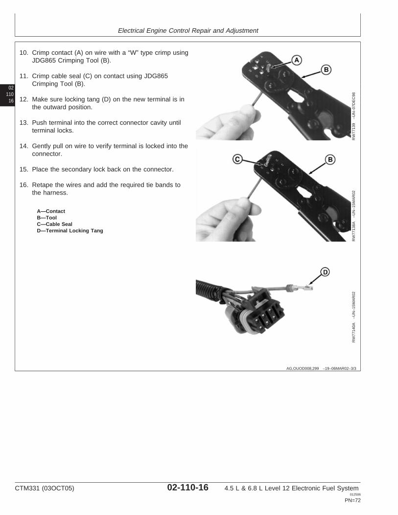
Electrical Engine Control Repair and Adjustment
02110
16
AG,OUOD008,299 –19–06MAR02–3/3
RW
7713
9–U
N–0
7DE
C98
RW
7713
8A–U
N–1
5MA
R02
RW
7714
0A–U
N–1
5MA
R02
A—ContactB—ToolC—Cable SealD—Terminal Locking Tang
10. Crimp contact (A) on wire with a “W” type crimp usingJDG865 Crimping Tool (B).
11. Crimp cable seal (C) on contact using JDG865Crimping Tool (B).
12. Make sure locking tang (D) on the new terminal is inthe outward position.
13. Push terminal into the correct connector cavity untilterminal locks.
14. Gently pull on wire to verify terminal is locked into theconnector.
15. Place the secondary lock back on the connector.
16. Retape the wires and add the required tie bands tothe harness.
CTM331 (03OCT05) 02-110-16 4.5 L & 6.8 L Level 12 Electronic Fuel System012506
PN=72
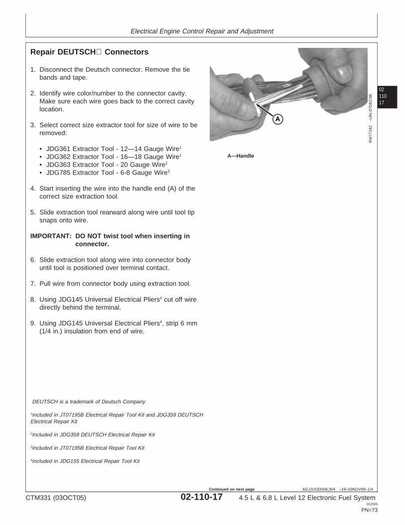
Electrical Engine Control Repair and Adjustment
0211017
AG,OUOD008,304 –19–03NOV99–1/4
Repair DEUTSCH Connectors
RW
7714
2–U
N–0
7DE
C98
A—Handle
1. Disconnect the Deutsch connector. Remove the tiebands and tape.
2. Identify wire color/number to the connector cavity.Make sure each wire goes back to the correct cavitylocation.
3. Select correct size extractor tool for size of wire to beremoved:
• JDG361 Extractor Tool - 12—14 Gauge Wire1
• JDG362 Extractor Tool - 16—18 Gauge Wire1
• JDG363 Extractor Tool - 20 Gauge Wire2
• JDG785 Extractor Tool - 6-8 Gauge Wire3
4. Start inserting the wire into the handle end (A) of thecorrect size extraction tool.
5. Slide extraction tool rearward along wire until tool tipsnaps onto wire.
IMPORTANT: DO NOT twist tool when inserting inconnector.
6. Slide extraction tool along wire into connector bodyuntil tool is positioned over terminal contact.
7. Pull wire from connector body using extraction tool.
8. Using JDG145 Universal Electrical Pliers4 cut off wiredirectly behind the terminal.
9. Using JDG145 Universal Electrical Pliers4, strip 6 mm(1/4 in.) insulation from end of wire.
DEUTSCH is a trademark of Deutsch Company
1Included in JT07195B Electrical Repair Tool Kit and JDG359 DEUTSCHElectrical Repair Kit
2Included in JDG359 DEUTSCH Electrical Repair Kit
3Included in JT07195B Electrical Repair Tool Kit
4Included in JDG155 Electrical Repair Tool Kit
CTM331 (03OCT05) 02-110-17 4.5 L & 6.8 L Level 12 Electronic Fuel System012506
PN=73
Continued on next page
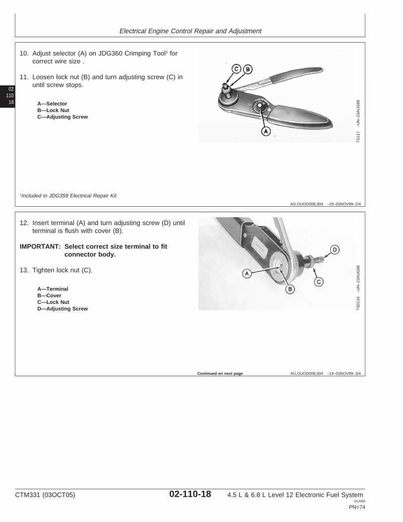
Electrical Engine Control Repair and Adjustment
02110
18
AG,OUOD008,304 –19–03NOV99–2/4
TS
117
–UN
–23A
UG
88A—SelectorB—Lock NutC—Adjusting Screw
10. Adjust selector (A) on JDG360 Crimping Tool1 forcorrect wire size .
11. Loosen lock nut (B) and turn adjusting screw (C) inuntil screw stops.
1Included in JDG359 Electrical Repair Kit
AG,OUOD008,304 –19–03NOV99–3/4
TS
0134
–UN
–23A
UG
88
A—TerminalB—CoverC—Lock NutD—Adjusting Screw
12. Insert terminal (A) and turn adjusting screw (D) untilterminal is flush with cover (B).
IMPORTANT: Select correct size terminal to fitconnector body.
13. Tighten lock nut (C).
Continued on next page
CTM331 (03OCT05) 02-110-18 4.5 L & 6.8 L Level 12 Electronic Fuel System012506
PN=74
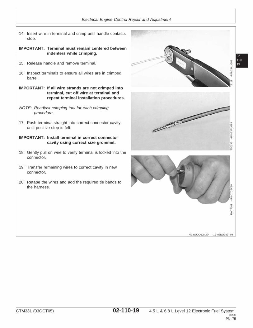
Electrical Engine Control Repair and Adjustment
0211019
AG,OUOD008,304 –19–03NOV99–4/4T
S11
8–U
N–2
3AU
G88
TS
0135
–UN
–23A
UG
88R
W77
141
–UN
–07D
EC
98
14. Insert wire in terminal and crimp until handle contactsstop.
IMPORTANT: Terminal must remain centered betweenindenters while crimping.
15. Release handle and remove terminal.
16. Inspect terminals to ensure all wires are in crimpedbarrel.
IMPORTANT: If all wire strands are not crimped intoterminal, cut off wire at terminal andrepeat terminal installation procedures.
NOTE: Readjust crimping tool for each crimpingprocedure.
17. Push terminal straight into correct connector cavityuntil positive stop is felt.
IMPORTANT: Install terminal in correct connectorcavity using correct size grommet.
18. Gently pull on wire to verify terminal is locked into theconnector.
19. Transfer remaining wires to correct cavity in newconnector.
20. Retape the wires and add the required tie bands tothe harness.
CTM331 (03OCT05) 02-110-19 4.5 L & 6.8 L Level 12 Electronic Fuel System012506
PN=75
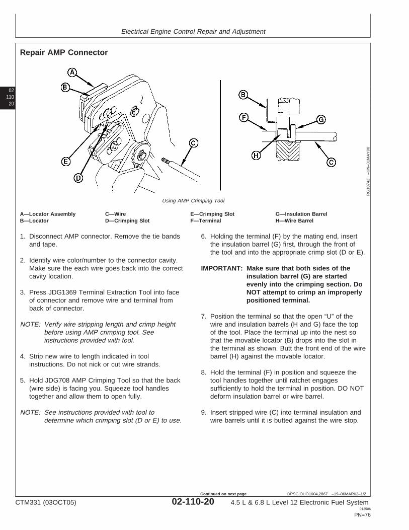
Electrical Engine Control Repair and Adjustment
02110
20
DPSG,OUO1004,2867 –19–06MAR02–1/2
Repair AMP Connector
RG
1074
2–U
N–3
1MA
Y00
Using AMP Crimping Tool
A—Locator Assembly C—Wire E—Crimping Slot G—Insulation BarrelB—Locator D—Crimping Slot F—Terminal H—Wire Barrel
1. Disconnect AMP connector. Remove the tie bandsand tape.
2. Identify wire color/number to the connector cavity.Make sure the each wire goes back into the correctcavity location.
3. Press JDG1369 Terminal Extraction Tool into faceof connector and remove wire and terminal fromback of connector.
NOTE: Verify wire stripping length and crimp heightbefore using AMP crimping tool. Seeinstructions provided with tool.
4. Strip new wire to length indicated in toolinstructions. Do not nick or cut wire strands.
5. Hold JDG708 AMP Crimping Tool so that the back(wire side) is facing you. Squeeze tool handlestogether and allow them to open fully.
NOTE: See instructions provided with tool todetermine which crimping slot (D or E) to use.
6. Holding the terminal (F) by the mating end, insertthe insulation barrel (G) first, through the front ofthe tool and into the appropriate crimp slot (D or E).
IMPORTANT: Make sure that both sides of theinsulation barrel (G) are startedevenly into the crimping section. DoNOT attempt to crimp an improperlypositioned terminal.
7. Position the terminal so that the open “U” of thewire and insulation barrels (H and G) face the topof the tool. Place the terminal up into the nest sothat the movable locator (B) drops into the slot inthe terminal as shown. Butt the front end of the wirebarrel (H) against the movable locator.
8. Hold the terminal (F) in position and squeeze thetool handles together until ratchet engagessufficiently to hold the terminal in position. DO NOTdeform insulation barrel or wire barrel.
9. Insert stripped wire (C) into terminal insulation andwire barrels until it is butted against the wire stop.
CTM331 (03OCT05) 02-110-20 4.5 L & 6.8 L Level 12 Electronic Fuel System012506
PN=76
Continued on next page
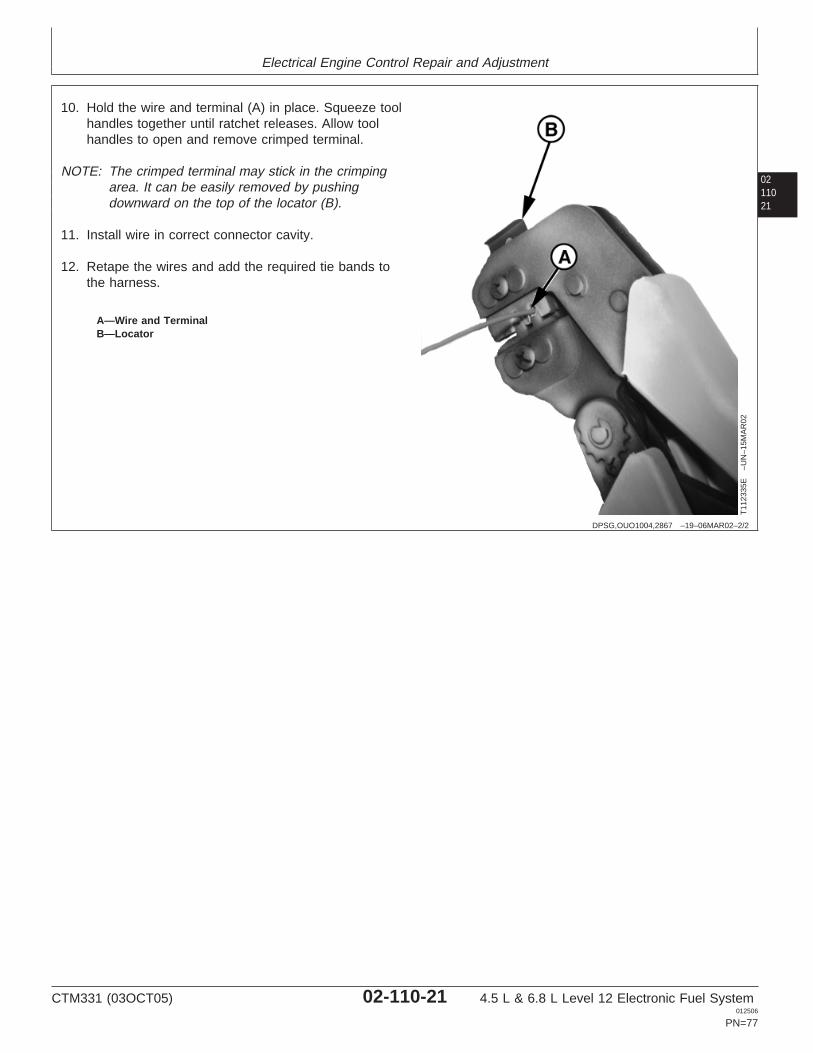
Electrical Engine Control Repair and Adjustment
0211021
DPSG,OUO1004,2867 –19–06MAR02–2/2
T11
2335
E–U
N–1
5MA
R02
A—Wire and TerminalB—Locator
10. Hold the wire and terminal (A) in place. Squeeze toolhandles together until ratchet releases. Allow toolhandles to open and remove crimped terminal.
NOTE: The crimped terminal may stick in the crimpingarea. It can be easily removed by pushingdownward on the top of the locator (B).
11. Install wire in correct connector cavity.
12. Retape the wires and add the required tie bands tothe harness.
CTM331 (03OCT05) 02-110-21 4.5 L & 6.8 L Level 12 Electronic Fuel System012506
PN=77
Electrical Engine Control Repair and Adjustment
02110
22
CTM331 (03OCT05) 02-110-22 4.5 L & 6.8 L Level 12 Electronic Fuel System012506
PN=78
Section 03Theory of Operation
Contents
Page
Group 130—Electronic Fuel System OperationAbout this Group . . . . . . . . . . . . . . . . . . . . . . .03-130-1 03Fuel System Operation . . . . . . . . . . . . . . . . . .03-130-2Fuel Supply Pump Operation . . . . . . . . . . . . .03-130-4Final Fuel Filter Operation. . . . . . . . . . . . . . . .03-130-5Fuel Injection Pump Operation . . . . . . . . . . . .03-130-6Fuel Injection Nozzle Operation. . . . . . . . . . . .03-130-8
Group 140—Electronic Control System OperationAbout This Group . . . . . . . . . . . . . . . . . . . . . .03-140-1Electronic Control System Terminology . . . . . .03-140-2Electronic Control System Operation. . . . . . . .03-140-3Monitoring Engine Parameters . . . . . . . . . . . .03-140-3Electronic Control System Overview . . . . . . . .03-140-4Measuring Temperature . . . . . . . . . . . . . . . . .03-140-5Measuring Pressure . . . . . . . . . . . . . . . . . . . .03-140-7Measuring Throttle Position. . . . . . . . . . . . . . .03-140-8Measuring Engine Speed . . . . . . . . . . . . . . .03-140-11Marine Throttle Control Options. . . . . . . . . . .03-140-12Engine Synchronization Throttle Control . . . .03-140-13Throttle Control Location Transfer . . . . . . . . .03-140-14Pump Solenoid . . . . . . . . . . . . . . . . . . . . . . .03-140-15Water in Fuel (WIF) Sensor. . . . . . . . . . . . . .03-140-15Engine Control Unit (ECU) . . . . . . . . . . . . . .03-140-17Controller Area Network (CAN) . . . . . . . . . . .03-140-18Cruise Control Operation. . . . . . . . . . . . . . . .03-140-19Intake Air Heater Operation. . . . . . . . . . . . . .03-140-19Engine Protection . . . . . . . . . . . . . . . . . . . . .03-140-20Derate Programs. . . . . . . . . . . . . . . . . . . . . .03-140-20Multiple Torque Curve Selection . . . . . . . . . .03-140-21Governor Droop Mode Selection . . . . . . . . . .03-140-21Engine Control Unit (ECU) Self-Diagnosis. . .03-140-22
CTM331 (03OCT05) 03-1 4.5 L & 6.8 L Level 12 Electronic Fuel System012506
PN=1
Contents
03
CTM331 (03OCT05) 03-2 4.5 L & 6.8 L Level 12 Electronic Fuel System012506
PN=2
Group 130Electronic Fuel System Operation
031301RG40854,000001C –19–03DEC01–1/1
About this Group
In this group, the fuel system information is described inthe following categories:
• Fuel System Operation• Fuel Supply Pump Operation• Final Fuel Filter Operation• Fuel Injection Pump Operation• Fuel Injection Nozzle Operation
CTM331 (03OCT05) 03-130-1 4.5 L & 6.8 L Level 12 Electronic Fuel System012506
PN=81
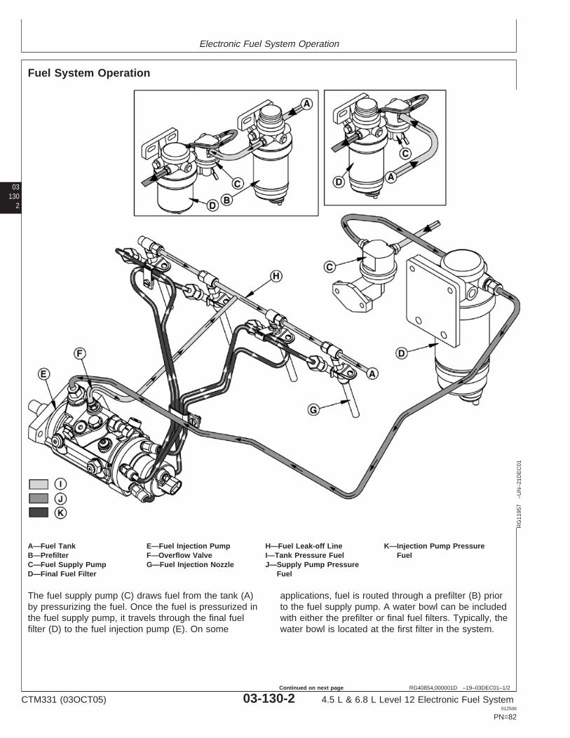
Electronic Fuel System Operation
03130
2
RG40854,000001D –19–03DEC01–1/2
Fuel System Operation
RG
1195
7–U
N–2
1DE
C01
A—Fuel Tank E—Fuel Injection Pump H—Fuel Leak-off Line K—Injection Pump PressureB—Prefilter F—Overflow Valve I—Tank Pressure Fuel FuelC—Fuel Supply Pump G—Fuel Injection Nozzle J—Supply Pump PressureD—Final Fuel Filter Fuel
The fuel supply pump (C) draws fuel from the tank (A)by pressurizing the fuel. Once the fuel is pressurized inthe fuel supply pump, it travels through the final fuelfilter (D) to the fuel injection pump (E). On some
applications, fuel is routed through a prefilter (B) priorto the fuel supply pump. A water bowl can be includedwith either the prefilter or final fuel filters. Typically, thewater bowl is located at the first filter in the system.
CTM331 (03OCT05) 03-130-2 4.5 L & 6.8 L Level 12 Electronic Fuel System012506
PN=82
Continued on next page
Electronic Fuel System Operation
031303RG40854,000001D –19–03DEC01–2/2
The fuel injection pump raises the required fuelpressure for injection. This high pressure fuel is routedthrough the delivery (pressure) lines to the fuelinjection nozzles (G). If there is excess fuel in theinjection pump, it is released through an overflow valve(F) and returned to tank through the fuel leak-off line(H).
Once the pressure of the fuel inside the injectionnozzle (G) overcomes the nozzle valve, fuel is forced
out a small orifice in the nozzle tip. This allows for fuelto atomize as it enters the combustion chamber.Excess fuel from the nozzles is routed through the fuelreturn leak-off line and returns to the fuel tank. Onsome applications, the fuel goes through a fuel coolerbefore returning to the fuel tank.
CTM331 (03OCT05) 03-130-3 4.5 L & 6.8 L Level 12 Electronic Fuel System012506
PN=83
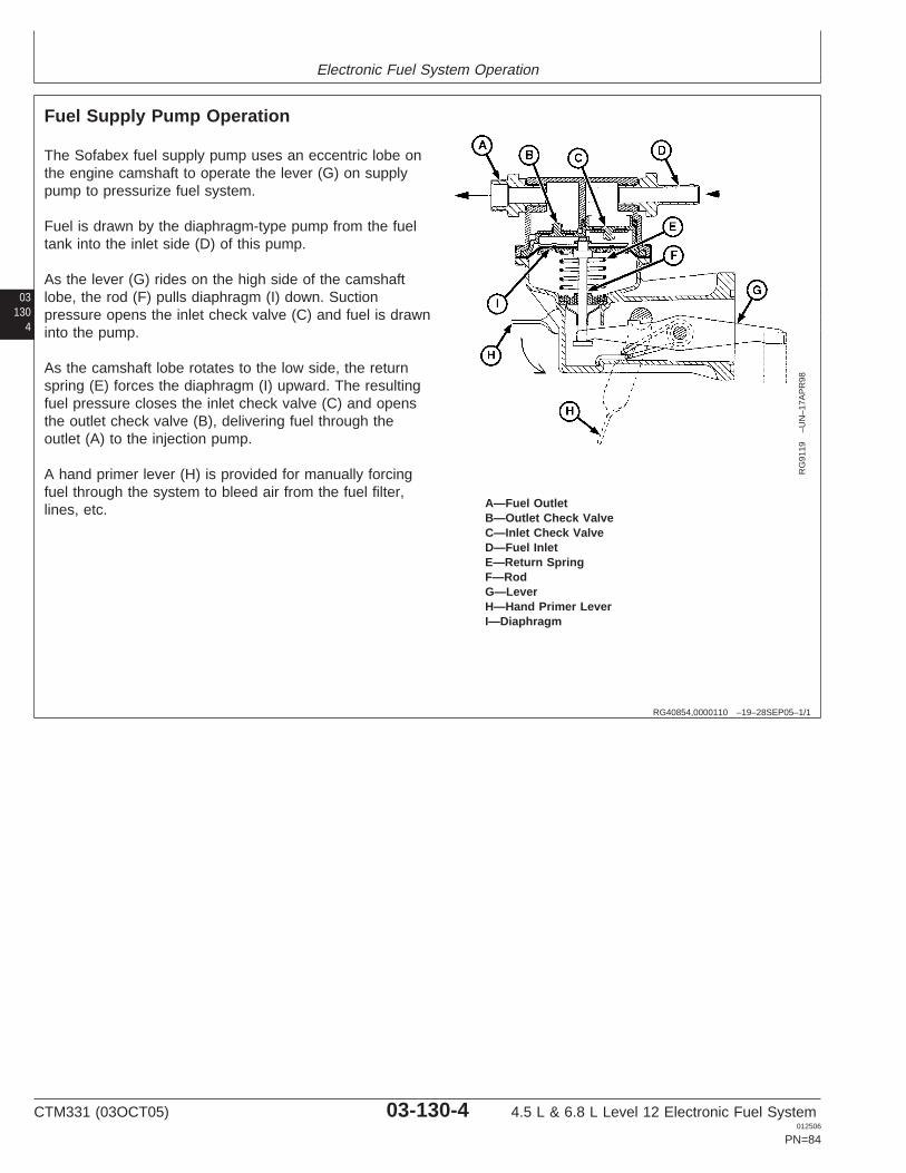
Electronic Fuel System Operation
03130
4
RG40854,0000110 –19–28SEP05–1/1
Fuel Supply Pump Operation
RG
9119
–UN
–17A
PR
98
A—Fuel OutletB—Outlet Check ValveC—Inlet Check ValveD—Fuel InletE—Return SpringF—RodG—LeverH—Hand Primer LeverI—Diaphragm
The Sofabex fuel supply pump uses an eccentric lobe onthe engine camshaft to operate the lever (G) on supplypump to pressurize fuel system.
Fuel is drawn by the diaphragm-type pump from the fueltank into the inlet side (D) of this pump.
As the lever (G) rides on the high side of the camshaftlobe, the rod (F) pulls diaphragm (I) down. Suctionpressure opens the inlet check valve (C) and fuel is drawninto the pump.
As the camshaft lobe rotates to the low side, the returnspring (E) forces the diaphragm (I) upward. The resultingfuel pressure closes the inlet check valve (C) and opensthe outlet check valve (B), delivering fuel through theoutlet (A) to the injection pump.
A hand primer lever (H) is provided for manually forcingfuel through the system to bleed air from the fuel filter,lines, etc.
CTM331 (03OCT05) 03-130-4 4.5 L & 6.8 L Level 12 Electronic Fuel System012506
PN=84
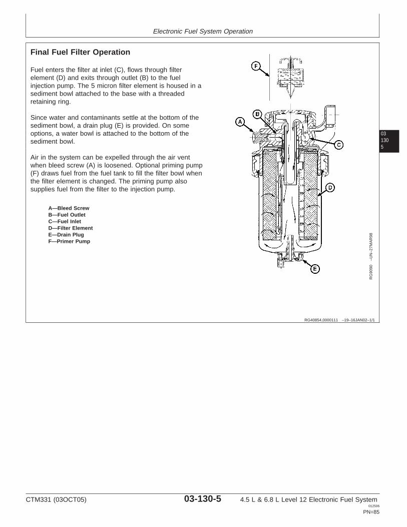
Electronic Fuel System Operation
031305
RG40854,0000111 –19–16JAN02–1/1
Final Fuel Filter Operation
RG
9090
–UN
–27M
AR
98
A—Bleed ScrewB—Fuel OutletC—Fuel InletD—Filter ElementE—Drain PlugF—Primer Pump
Fuel enters the filter at inlet (C), flows through filterelement (D) and exits through outlet (B) to the fuelinjection pump. The 5 micron filter element is housed in asediment bowl attached to the base with a threadedretaining ring.
Since water and contaminants settle at the bottom of thesediment bowl, a drain plug (E) is provided. On someoptions, a water bowl is attached to the bottom of thesediment bowl.
Air in the system can be expelled through the air ventwhen bleed screw (A) is loosened. Optional priming pump(F) draws fuel from the fuel tank to fill the filter bowl whenthe filter element is changed. The priming pump alsosupplies fuel from the filter to the injection pump.
CTM331 (03OCT05) 03-130-5 4.5 L & 6.8 L Level 12 Electronic Fuel System012506
PN=85
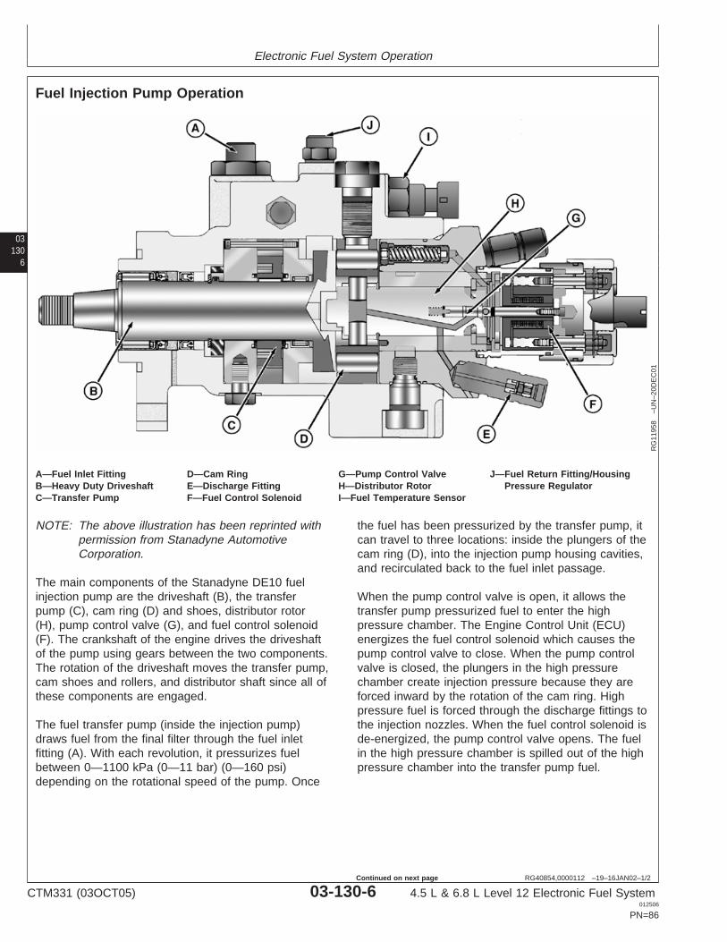
Electronic Fuel System Operation
03130
6
RG40854,0000112 –19–16JAN02–1/2
Fuel Injection Pump Operation
RG
1195
8–U
N–2
0DE
C01
A—Fuel Inlet Fitting D—Cam Ring G—Pump Control Valve J—Fuel Return Fitting/HousingB—Heavy Duty Driveshaft E—Discharge Fitting H—Distributor Rotor Pressure RegulatorC—Transfer Pump F—Fuel Control Solenoid I—Fuel Temperature Sensor
NOTE: The above illustration has been reprinted withpermission from Stanadyne AutomotiveCorporation.
The main components of the Stanadyne DE10 fuelinjection pump are the driveshaft (B), the transferpump (C), cam ring (D) and shoes, distributor rotor(H), pump control valve (G), and fuel control solenoid(F). The crankshaft of the engine drives the driveshaftof the pump using gears between the two components.The rotation of the driveshaft moves the transfer pump,cam shoes and rollers, and distributor shaft since all ofthese components are engaged.
The fuel transfer pump (inside the injection pump)draws fuel from the final filter through the fuel inletfitting (A). With each revolution, it pressurizes fuelbetween 0—1100 kPa (0—11 bar) (0—160 psi)depending on the rotational speed of the pump. Once
the fuel has been pressurized by the transfer pump, itcan travel to three locations: inside the plungers of thecam ring (D), into the injection pump housing cavities,and recirculated back to the fuel inlet passage.
When the pump control valve is open, it allows thetransfer pump pressurized fuel to enter the highpressure chamber. The Engine Control Unit (ECU)energizes the fuel control solenoid which causes thepump control valve to close. When the pump controlvalve is closed, the plungers in the high pressurechamber create injection pressure because they areforced inward by the rotation of the cam ring. Highpressure fuel is forced through the discharge fittings tothe injection nozzles. When the fuel control solenoid isde-energized, the pump control valve opens. The fuelin the high pressure chamber is spilled out of the highpressure chamber into the transfer pump fuel.
CTM331 (03OCT05) 03-130-6 4.5 L & 6.8 L Level 12 Electronic Fuel System012506
PN=86
Continued on next page
Electronic Fuel System Operation
031307RG40854,0000112 –19–16JAN02–2/2
Some of the transfer pump pressure fuel is releasedthrough a port that contains a vent wire into injectionpump housing cavities. The purpose of housingpressure fuel is to keep the injection pumpcomponents cooled and lubricated. The amount of fuelthat is released into the housing is determined by thesize of the vent wire. The pressure of the housing iscontrolled by the fuel return fitting/pressure regulator(J). If the pressure exceeds the regulator, it will returnfuel to the fuel tank. The ECU monitors the fuel
temperature of the housing through a fuel temperaturesensor (I). For more information on the fueltemperature sensor, see MEASURINGTEMPERATURE in Group 140 of this Section.
The remaining transfer pump pressure fuel travelsthrough a transfer pump regulating valve. This allowsfor fuel to return to injection pump inlet pressure. Itcirculates the fuel back through the transfer pump.
CTM331 (03OCT05) 03-130-7 4.5 L & 6.8 L Level 12 Electronic Fuel System012506
PN=87
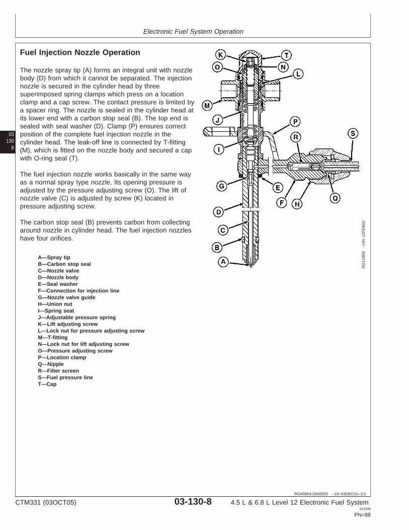
Electronic Fuel System Operation
03130
8
RG40854,0000020 –19–03DEC01–1/1
Fuel Injection Nozzle Operation
RG
1195
9–U
N–1
2FE
B02
A—Spray tipB—Carbon stop sealC—Nozzle valveD—Nozzle bodyE—Seal washerF—Connection for injection lineG—Nozzle valve guideH—Union nutI—Spring seatJ—Adjustable pressure springK—Lift adjusting screwL—Lock nut for pressure adjusting screwM—T-fittingN—Lock nut for lift adjusting screwO—Pressure adjusting screwP—Location clampQ—NippleR—Filter screenS—Fuel pressure lineT—Cap
The nozzle spray tip (A) forms an integral unit with nozzlebody (D) from which it cannot be separated. The injectionnozzle is secured in the cylinder head by threesuperimposed spring clamps which press on a locationclamp and a cap screw. The contact pressure is limited bya spacer ring. The nozzle is sealed in the cylinder head atits lower end with a carbon stop seal (B). The top end issealed with seal washer (D). Clamp (P) ensures correctposition of the complete fuel injection nozzle in thecylinder head. The leak-off line is connected by T-fitting(M), which is fitted on the nozzle body and secured a capwith O-ring seal (T).
The fuel injection nozzle works basically in the same wayas a normal spray type nozzle. Its opening pressure isadjusted by the pressure adjusting screw (O). The lift ofnozzle valve (C) is adjusted by screw (K) located inpressure adjusting screw.
The carbon stop seal (B) prevents carbon from collectingaround nozzle in cylinder head. The fuel injection nozzleshave four orifices.
CTM331 (03OCT05) 03-130-8 4.5 L & 6.8 L Level 12 Electronic Fuel System012506
PN=88
Group 140Electronic Control System Operation
031401
RG40854,0000021 –19–04OCT05–1/1
About This Group
In this group, the electronic control system is described inthe following categories:
• Electronic Control System Terminology• Electronic Control System Operation• Monitoring Engine Parameters• Electronic Control System• Measuring Temperature
– ECT (Engine Coolant Temperature) Sensor– MAT (Manifold Air Temperature) Sensor– Loss of Coolant Temperature Sensor– Fuel Temperature Sensor
• Measuring Pressure– Oil Pressure Sensor
• Measuring Throttle Position• Measuring Engine Speed
– Crank Position Sensor• Marine Throttle Control Options
– Engine Synchronization Throttle Control– Throttle Control Location Control
• Pump Solenoid• Water in Fuel (WIF) Sensor• Engine Control Unit (ECU)• Controller Area Network (CAN)• Cruise Control Operation• Intake Air Heater Operation• Engine Protection• Derate Programs• Multiple Torque Curves Selection• Governor Droop Mode Selection• Engine Control Unit (ECU) Self Diagnosis
CTM331 (03OCT05) 03-140-1 4.5 L & 6.8 L Level 12 Electronic Fuel System012506
PN=89
Electronic Control System Operation
03140
2
RG40854,0000023 –19–03DEC01–1/1
Electronic Control System Terminology
Actuator A device controlled by the (ECU) to perform a certain function.
Analog Signal which has a continuous range of possible voltages. Usually 0 to 5 volt or 0 to 12 volt signals.
Boost Air charge pressure in the intake manifold.
CAN Controller Area Network. The electronic pathway network on vehicles that allows communication betweencontrollers.
DTC Diagnostic Trouble Code. A code which is stored in the ECU’s memory when the ECU detects a problem in theelectronic control system.
Digital A signal which consists of only two-volt levels — usually 0 volts and +5 volts.
ECT Engine Coolant Temperature (sensor). Measures the temperature of the engine coolant. See MEASURINGTEMPERATURE later in this Group for details.
ECU Engine Control Unit. The computer which controls the fuel, air, and ignition systems on the engine. See ENGINECONTROL UNIT (ECU) later in this Group for details.
FMI Failure Mode Identifier. The second part of a two-part code that identifies control system trouble codes accordingto the SAE J1939 standard. The FMI identifies the type of failure that has occurred. The first half of the code isthe Suspect Parameter Number (SPN).
J1587/J1708 The Society of Automotive Engineers (SAE) standard for the electronic components of heavy duty vehicles. J1587is the software standard. J1708 is the hardware standard.
MAT Manifold Air Temperature (sensor). Measures the temperature of the air in the intake manifold. See MEASURINGTEMPERATURE later in this Group for details.
PROM Programmable, Read-Only Memory. The computer chip which contains the calibration information for the enginecontrol system. See ENGINE CONTROL UNIT (ECU) later in this Group for details.
PWM Pulse Width Modulation. A digital signal (not analog) which consists of a pulse generated at a fixed frequency.When an actuator is controlled by a PWM signal, the on time of the signal is increased or decreased (modulated)to increase or decrease the output of the actuator.
RAM Random Access Memory. The portion of computer memory within the ECU which changes as the engine isrunning and is stored while the engine is off. See ENGINE CONTROL UNIT (ECU) later in this Group for details.
SAE Society of Automotive Engineers. Working with society to promote vehicle safety and maintenance and energyresource conservation.
Sensor Device used by the ECU to monitor various engine parameters.
SPN Suspect Parameter Number. The first half of a two-part code that identifies control system fault codes accordingto the SAE J1939 Standard. The SPN identifies the system or component that has the failure. The second half ofthe code is the Failure Mode Identifier (FMI).
VBAT Battery voltage or unswitched voltage.
VSW Switched voltage
CTM331 (03OCT05) 03-140-2 4.5 L & 6.8 L Level 12 Electronic Fuel System012506
PN=90
Electronic Control System Operation
031403
RG40854,0000022 –19–03DEC01–1/1
Electronic Control System Operation
Engine Starting Mode
When the key is turned to the “ON” position, aswitched power voltage is sent to the Engine ControlUnit (ECU). This energizes the ECU and allows it to“boot-up” and ready itself for engine start.
NOTE: If a wiring problem prevents the key ON signalfrom getting to the ECU, the engine will notstart.
As soon as the ECU receives an input from thecrankshaft position sensor that the engine is cranking,it will move the pump control valve to the “pressure”position, which will allow injection pressure to bedeveloped. The fuel is delivered to all of the cylinders.To provide cold temperature enrichment, the amount offuel injected is based on the temperature measured by
the Engine Coolant Temperature (ECT) sensor. At thispoint, the engine will start and the ECU will go into therunning mode.
Engine Running Mode
In the running mode, the ECU monitors informationfrom the various sensors, then determines theoptimum amount of fuel to inject and the optimuminjection timing in order to allow the engine to develophigh power while maintaining low exhaust emissionoutput. The ECU controls fuel delivery by energizingand de-engergizing the pump control valve solenoid.When the ECU energizes the solenoid, the pumpcontrol valve closes and injection begins. When thecorrect amount of fuel has been injected, the ECUde-energizes the solenoid, causing the pump controlvalve to open, and fuel injection to stop.
RG40854,0000026 –19–03DEC01–1/1
Monitoring Engine Parameters
In order for the electronic control system to deliver fuelaccording to a given set of operating conditions, thefollowing parameters are monitored by the ECU:
• Engine Coolant Temperature (ECT)• Loss of Coolant Temperature• Manifold Air Temperature (MAT)• Oil Pressure• Fuel Temperature• Throttle Position• Crankshaft Position Sensor
CTM331 (03OCT05) 03-140-3 4.5 L & 6.8 L Level 12 Electronic Fuel System012506
PN=91
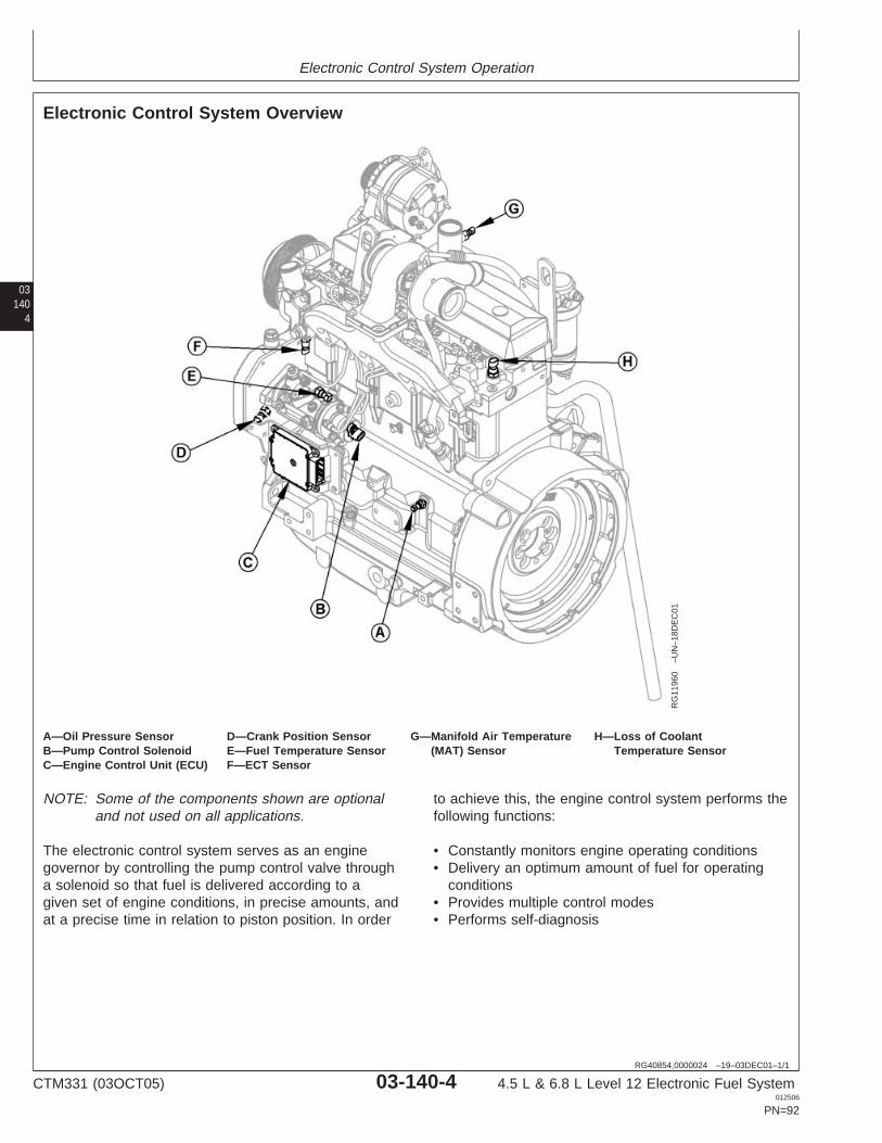
Electronic Control System Operation
03140
4
RG40854,0000024 –19–03DEC01–1/1
Electronic Control System Overview
RG
1196
0–U
N–1
8DE
C01
A—Oil Pressure Sensor D—Crank Position Sensor G—Manifold Air Temperature H—Loss of CoolantB—Pump Control Solenoid E—Fuel Temperature Sensor (MAT) Sensor Temperature SensorC—Engine Control Unit (ECU) F—ECT Sensor
NOTE: Some of the components shown are optionaland not used on all applications.
The electronic control system serves as an enginegovernor by controlling the pump control valve througha solenoid so that fuel is delivered according to agiven set of engine conditions, in precise amounts, andat a precise time in relation to piston position. In order
to achieve this, the engine control system performs thefollowing functions:
• Constantly monitors engine operating conditions• Delivery an optimum amount of fuel for operating
conditions• Provides multiple control modes• Performs self-diagnosis
CTM331 (03OCT05) 03-140-4 4.5 L & 6.8 L Level 12 Electronic Fuel System012506
PN=92
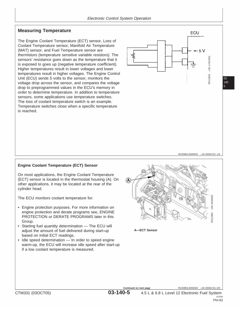
Electronic Control System Operation
031405
RG40854,0000025 –19–03DEC01–1/5
Measuring Temperature
RG
1181
9–U
N–1
7AU
G01
The Engine Coolant Temperature (ECT) sensor, Loss ofCoolant Temperature sensor, Manifold Air Temperature(MAT) sensor, and Fuel Temperature sensor arethermistors (temperature sensitive variable resistors). Thesensors’ resistance goes down as the temperature that itis exposed to goes up (negative temperature coefficient).Higher temperatures result in lower voltages and lowertemperatures result in higher voltages. The Engine ControlUnit (ECU) sends 5 volts to the sensor, monitors thevoltage drop across the sensor, and compares the voltagedrop to preprogrammed values in the ECU’s memory inorder to determine temperature. In addition to temperaturesensors, some applications use temperature switches.The loss of coolant temperature switch is an example.Temperature switches close when a specific temperatureis reached.
RG40854,0000025 –19–03DEC01–2/5
RG
1196
3–U
N–2
9JA
N02
A—ECT Sensor
Engine Coolant Temperature (ECT) Sensor
On most applications, the Engine Coolant Temperature(ECT) sensor is located in the thermostat housing (A). Onother applications, it may be located at the rear of thecylinder head.
The ECU monitors coolant temperature for:
• Engine protection purposes. For more information onengine protection and derate programs see, ENGINEPROTECTION or DERATE PROGRAMS later in thisGroup.
• Starting fuel quantity determination — The ECU willadjust the amount of fuel delivered during start-upbased on initial ECT readings.
• Idle speed determination — In order to speed enginewarm-up, the ECU will increase idle speed after start-upif a low coolant temperature is measured.
CTM331 (03OCT05) 03-140-5 4.5 L & 6.8 L Level 12 Electronic Fuel System012506
PN=93
Continued on next page
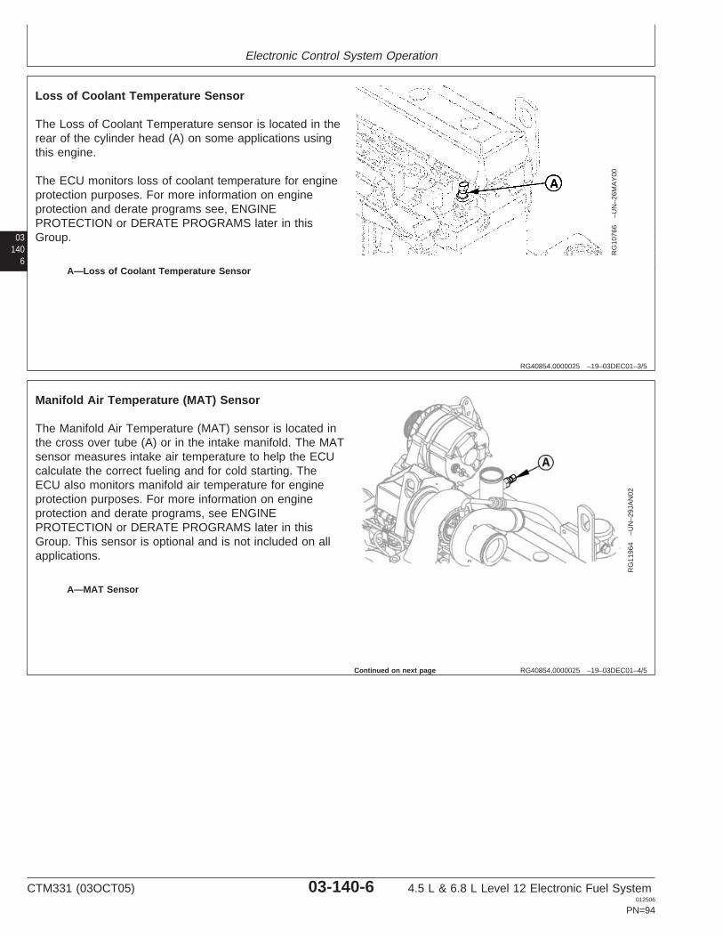
Electronic Control System Operation
03140
6
RG40854,0000025 –19–03DEC01–3/5
RG
1076
6–U
N–2
6MA
Y00
A—Loss of Coolant Temperature Sensor
Loss of Coolant Temperature Sensor
The Loss of Coolant Temperature sensor is located in therear of the cylinder head (A) on some applications usingthis engine.
The ECU monitors loss of coolant temperature for engineprotection purposes. For more information on engineprotection and derate programs see, ENGINEPROTECTION or DERATE PROGRAMS later in thisGroup.
RG40854,0000025 –19–03DEC01–4/5
RG
1196
4–U
N–2
9JA
N02
A—MAT Sensor
Manifold Air Temperature (MAT) Sensor
The Manifold Air Temperature (MAT) sensor is located inthe cross over tube (A) or in the intake manifold. The MATsensor measures intake air temperature to help the ECUcalculate the correct fueling and for cold starting. TheECU also monitors manifold air temperature for engineprotection purposes. For more information on engineprotection and derate programs, see ENGINEPROTECTION or DERATE PROGRAMS later in thisGroup. This sensor is optional and is not included on allapplications.
Continued on next page
CTM331 (03OCT05) 03-140-6 4.5 L & 6.8 L Level 12 Electronic Fuel System012506
PN=94
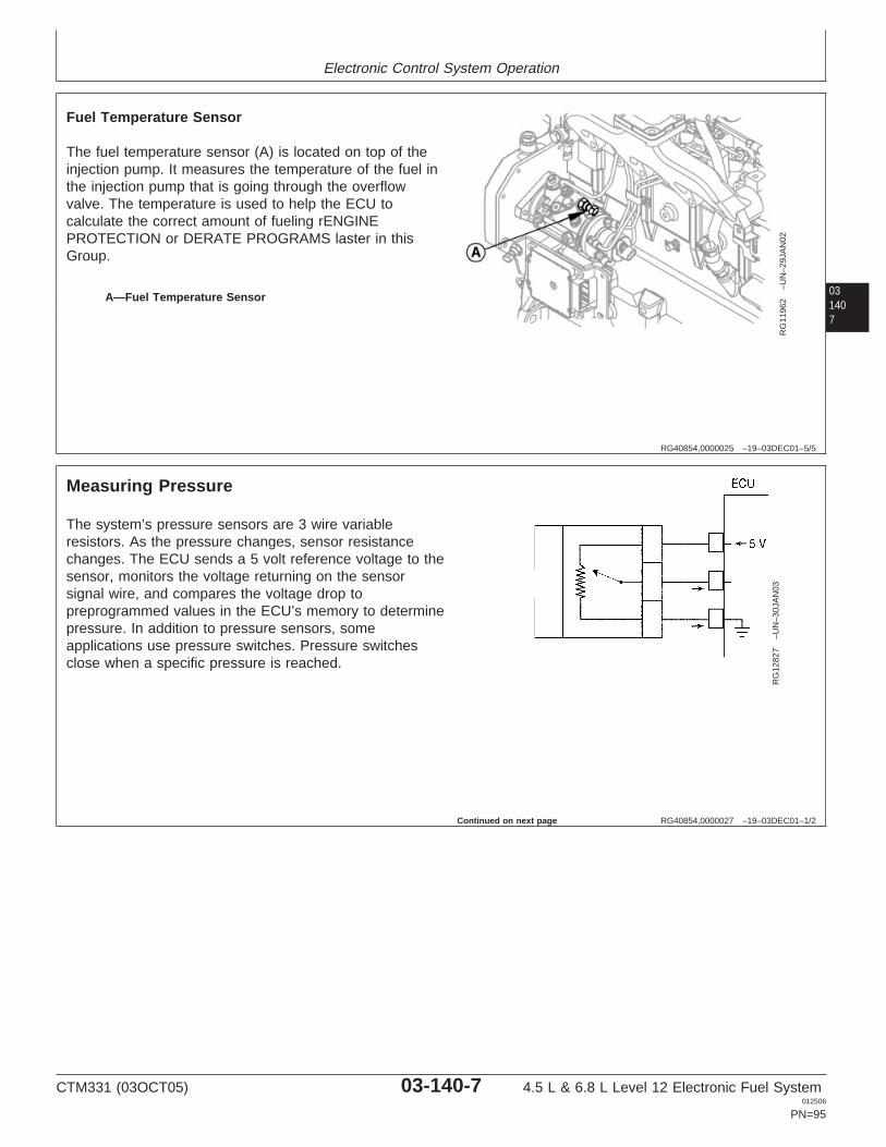
Electronic Control System Operation
031407
RG40854,0000025 –19–03DEC01–5/5
RG
1196
2–U
N–2
9JA
N02
A—Fuel Temperature Sensor
Fuel Temperature Sensor
The fuel temperature sensor (A) is located on top of theinjection pump. It measures the temperature of the fuel inthe injection pump that is going through the overflowvalve. The temperature is used to help the ECU tocalculate the correct amount of fueling rENGINEPROTECTION or DERATE PROGRAMS laster in thisGroup.
RG40854,0000027 –19–03DEC01–1/2
Measuring Pressure
RG
1282
7–U
N–3
0JA
N03
The system’s pressure sensors are 3 wire variableresistors. As the pressure changes, sensor resistancechanges. The ECU sends a 5 volt reference voltage to thesensor, monitors the voltage returning on the sensorsignal wire, and compares the voltage drop topreprogrammed values in the ECU’s memory to determinepressure. In addition to pressure sensors, someapplications use pressure switches. Pressure switchesclose when a specific pressure is reached.
Continued on next page
CTM331 (03OCT05) 03-140-7 4.5 L & 6.8 L Level 12 Electronic Fuel System012506
PN=95
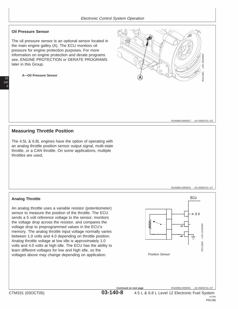
Electronic Control System Operation
03140
8
RG40854,0000027 –19–03DEC01–2/2
RG
1196
1–U
N–2
9JA
N02
A—Oil Pressure Sensor
Oil Pressure Sensor
The oil pressure sensor is an optional sensor located inthe main engine galley (A). The ECU monitors oilpressure for engine protection purposes. For moreinformation on engine protection and derate programssee, ENGINE PROTECTION or DERATE PROGRAMSlater in this Group.
RG40854,0000031 –19–05DEC01–1/7
Measuring Throttle Position
The 4.5L & 6.8L engines have the option of operating withan analog throttle position sensor output signal, multi-statethrottle, or a CAN throttle. On some applications, multiplethrottles are used.
RG40854,0000031 –19–05DEC01–2/7
RG
1182
0–U
N–1
5JA
N03
Position Sensor
Analog Throttle
An analog throttle uses a variable resistor (potentiometer)sensor to measure the position of the throttle. The ECUsends a 5 volt reference voltage to the sensor, monitorsthe voltage drop across the resistor, and compares thevoltage drop to preprogrammed values in the ECU’smemory. The analog throttle input voltage normally variesbetween 1.0 volts and 4.0 depending on throttle position.Analog throttle voltage at low idle is approximately 1.0volts and 4.0 volts at high idle. The ECU has the ability tolearn different voltages for low and high idle, so thevoltages above may change depending on application.
CTM331 (03OCT05) 03-140-8 4.5 L & 6.8 L Level 12 Electronic Fuel System012506
PN=96
Continued on next page
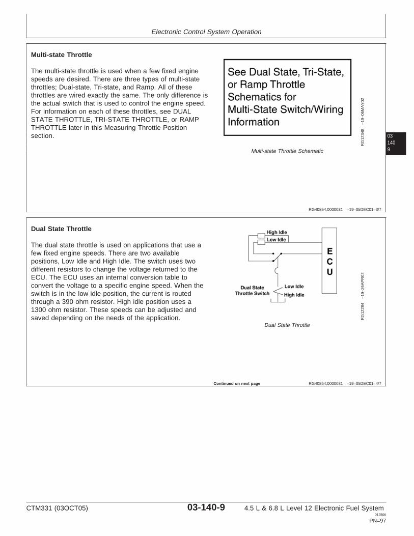
Electronic Control System Operation
031409
RG40854,0000031 –19–05DEC01–3/7
RG
1234
8–1
9–06
MA
Y02
Multi-state Throttle Schematic
Multi-state Throttle
The multi-state throttle is used when a few fixed enginespeeds are desired. There are three types of multi-statethrottles; Dual-state, Tri-state, and Ramp. All of thesethrottles are wired exactly the same. The only difference isthe actual switch that is used to control the engine speed.For information on each of these throttles, see DUALSTATE THROTTLE, TRI-STATE THROTTLE, or RAMPTHROTTLE later in this Measuring Throttle Positionsection.
RG40854,0000031 –19–05DEC01–4/7
RG
1228
4–1
9–26
AP
R02
Dual State Throttle
Dual State Throttle
The dual state throttle is used on applications that use afew fixed engine speeds. There are two availablepositions, Low Idle and High Idle. The switch uses twodifferent resistors to change the voltage returned to theECU. The ECU uses an internal conversion table toconvert the voltage to a specific engine speed. When theswitch is in the low idle position, the current is routedthrough a 390 ohm resistor. High idle position uses a1300 ohm resistor. These speeds can be adjusted andsaved depending on the needs of the application.
Continued on next page
CTM331 (03OCT05) 03-140-9 4.5 L & 6.8 L Level 12 Electronic Fuel System012506
PN=97
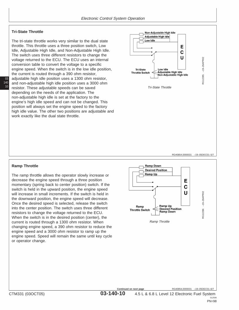
Electronic Control System Operation
03140
10
RG40854,0000031 –19–05DEC01–5/7
RG
1228
5–1
9–26
AP
R02
Tri-State Throttle
Tri-State Throttle
The tri-state throttle works very similar to the dual statethrottle. This throttle uses a three position switch, LowIdle, Adjustable High Idle, and Non-Adjustable High Idle.The switch uses three different resistors to change thevoltage returned to the ECU. The ECU uses an internalconversion table to convert the voltage to a specificengine speed. When the switch is in the low idle position,the current is routed through a 390 ohm resistor,adjustable high idle position uses a 1300 ohm resistor,and non-adjustable high idle position uses a 3000 ohmresistor. These adjustable speeds can be saveddepending on the needs of the application. Thenon-adjustable high idle is set at the factory to theengine’s high idle speed and can not be changed. Thisposition will always set the engine speed to the factoryhigh idle value. The other two positions are adjustable andwork exactly like the dual state throttle.
RG40854,0000031 –19–05DEC01–6/7
RG
1228
6–1
9–26
AP
R02
Ramp Throttle
Ramp Throttle
The ramp throttle allows the operator slowly increase ordecrease the engine speed through a three positionmomentary (spring back to center position) switch. If theswitch is held in the upward position, the engine speedwill increase in small increments. If the switch is held inthe downward position, the engine speed will decrease.Once the desired speed is selected, release the switchinto the center position. The switch uses three differentresistors to change the voltage returned to the ECU.When the switch is in the desired position (center), thecurrent is routed through a 1300 ohm resistor. Whenchanging engine speed, a 390 ohm resistor to reduce theengine speed and a 3000 ohm resistor to ramp up theengine speed. Speed will remain the same until key cycleor operator change.
CTM331 (03OCT05) 03-140-10 4.5 L & 6.8 L Level 12 Electronic Fuel System012506
PN=98
Continued on next page
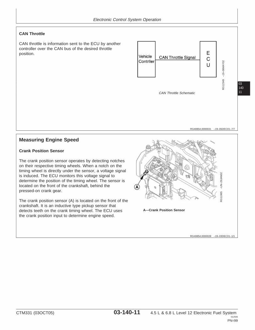
Electronic Control System Operation
0314011
RG40854,0000031 –19–05DEC01–7/7
RG
1234
9–1
9–06
MA
Y02
CAN Throttle Schematic
CAN Throttle
CAN throttle is information sent to the ECU by anothercontroller over the CAN bus of the desired throttleposition.
RG40854,0000028 –19–03DEC01–1/1
Measuring Engine Speed
RG
1196
5–U
N–2
9JA
N02
A—Crank Position Sensor
Crank Position Sensor
The crank position sensor operates by detecting notcheson their respective timing wheels. When a notch on thetiming wheel is directly under the sensor, a voltage signalis induced. The ECU monitors this voltage signal todetermine the position of the timing wheel. The sensor islocated on the front of the crankshaft, behind thepressed-on crank gear.
The crank position sensor (A) is located on the front of thecrankshaft. It is an inductive type pickup sensor thatdetects teeth on the crank timing wheel. The ECU usesthe crank position input to determine engine speed.
CTM331 (03OCT05) 03-140-11 4.5 L & 6.8 L Level 12 Electronic Fuel System012506
PN=99
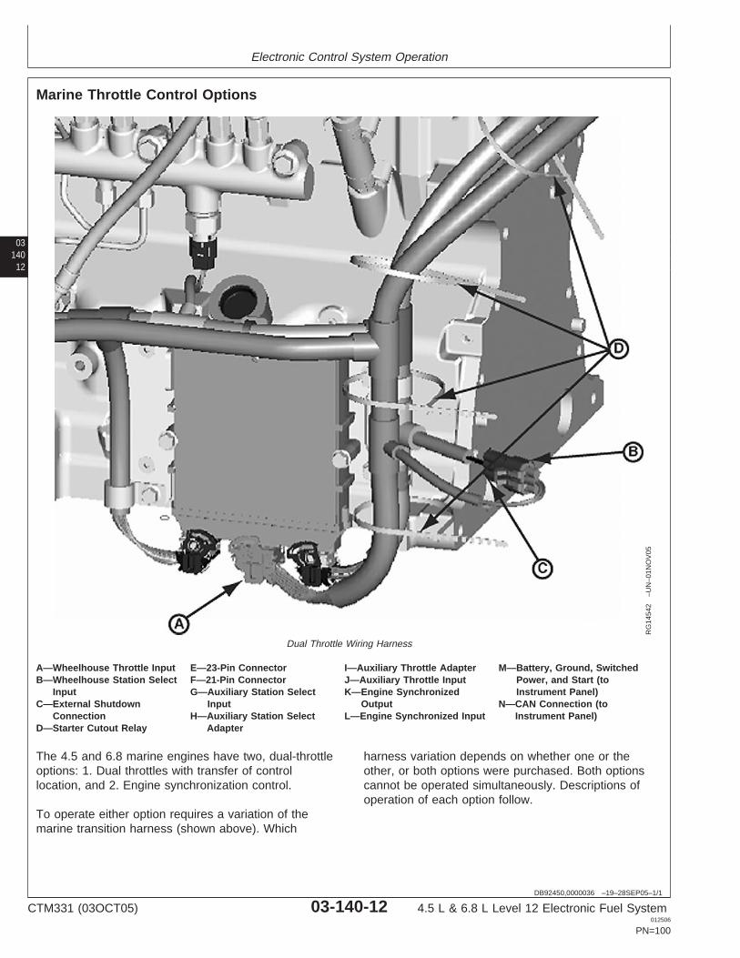
Electronic Control System Operation
03140
12
DB92450,0000036 –19–28SEP05–1/1
Marine Throttle Control Options
RG
1454
2–U
N–0
1NO
V05
Dual Throttle Wiring Harness
A—Wheelhouse Throttle Input E—23-Pin Connector I—Auxiliary Throttle Adapter M—Battery, Ground, SwitchedB—Wheelhouse Station Select F—21-Pin Connector J—Auxiliary Throttle Input Power, and Start (to
Input G—Auxiliary Station Select K—Engine Synchronized Instrument Panel)C—External Shutdown Input Output N—CAN Connection (to
Connection H—Auxiliary Station Select L—Engine Synchronized Input Instrument Panel)D—Starter Cutout Relay Adapter
The 4.5 and 6.8 marine engines have two, dual-throttleoptions: 1. Dual throttles with transfer of controllocation, and 2. Engine synchronization control.
To operate either option requires a variation of themarine transition harness (shown above). Which
harness variation depends on whether one or theother, or both options were purchased. Both optionscannot be operated simultaneously. Descriptions ofoperation of each option follow.
CTM331 (03OCT05) 03-140-12 4.5 L & 6.8 L Level 12 Electronic Fuel System012506
PN=100
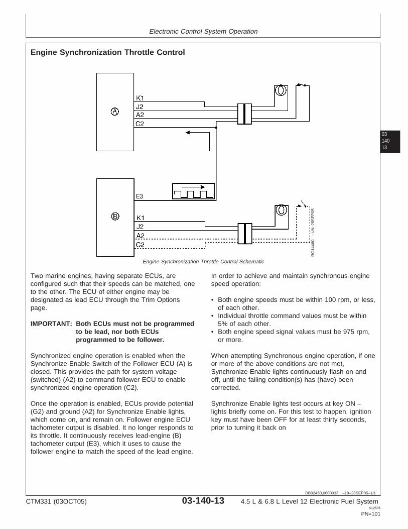
Electronic Control System Operation
0314013
DB92450,0000033 –19–28SEP05–1/1
Engine Synchronization Throttle Control
RG
1446
0–U
N–2
8SE
P05
Engine Synchronization Throttle Control Schematic
Two marine engines, having separate ECUs, areconfigured such that their speeds can be matched, oneto the other. The ECU of either engine may bedesignated as lead ECU through the Trim Optionspage.
IMPORTANT: Both ECUs must not be programmedto be lead, nor both ECUsprogrammed to be follower.
Synchronized engine operation is enabled when theSynchronize Enable Switch of the Follower ECU (A) isclosed. This provides the path for system voltage(switched) (A2) to command follower ECU to enablesynchronized engine operation (C2).
Once the operation is enabled, ECUs provide potential(G2) and ground (A2) for Synchronize Enable lights,which come on, and remain on. Follower engine ECUtachometer output is disabled. It no longer responds toits throttle. It continuously receives lead-engine (B)tachometer output (E3), which it uses to cause thefollower engine to match the speed of the lead engine.
In order to achieve and maintain synchronous enginespeed operation:
• Both engine speeds must be within 100 rpm, or less,of each other.
• Individual throttle command values must be within5% of each other.
• Both engine speed signal values must be 975 rpm,or more.
When attempting Synchronous engine operation, if oneor more of the above conditions are not met,Synchronize Enable lights continuously flash on andoff, until the failing condition(s) has (have) beencorrected.
Synchronize Enable lights test occurs at key ON –lights briefly come on. For this test to happen, ignitionkey must have been OFF for at least thirty seconds,prior to turning it back on
CTM331 (03OCT05) 03-140-13 4.5 L & 6.8 L Level 12 Electronic Fuel System012506
PN=101
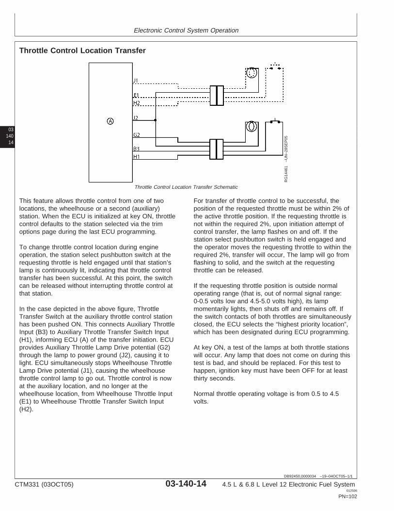
Electronic Control System Operation
03140
14
DB92450,0000034 –19–04OCT05–1/1
Throttle Control Location Transfer
RG
1446
1–U
N–2
8SE
P05
Throttle Control Location Transfer Schematic
This feature allows throttle control from one of twolocations, the wheelhouse or a second (auxiliary)station. When the ECU is initialized at key ON, throttlecontrol defaults to the station selected via the trimoptions page during the last ECU programming.
To change throttle control location during engineoperation, the station select pushbutton switch at therequesting throttle is held engaged until that station’slamp is continuously lit, indicating that throttle controltransfer has been successful. At this point, the switchcan be released without interrupting throttle control atthat station.
In the case depicted in the above figure, ThrottleTransfer Switch at the auxiliary throttle control stationhas been pushed ON. This connects Auxiliary ThrottleInput (B3) to Auxiliary Throttle Transfer Switch Input(H1), informing ECU (A) of the transfer initiation. ECUprovides Auxiliary Throttle Lamp Drive potential (G2)through the lamp to power ground (J2), causing it tolight. ECU simultaneously stops Wheelhouse ThrottleLamp Drive potential (J1), causing the wheelhousethrottle control lamp to go out. Throttle control is nowat the auxiliary location, and no longer at thewheelhouse location, from Wheelhouse Throttle Input(E1) to Wheelhouse Throttle Transfer Switch Input(H2).
For transfer of throttle control to be successful, theposition of the requested throttle must be within 2% ofthe active throttle position. If the requesting throttle isnot within the required 2%, upon initiation attempt ofcontrol transfer, the lamp flashes on and off. If thestation select pushbutton switch is held engaged andthe operator moves the requesting throttle to within therequired 2%, transfer will occur, The lamp will go fromflashing to solid, and the switch at the requestingthrottle can be released.
If the requesting throttle position is outside normaloperating range (that is, out of normal signal range:0-0.5 volts low and 4.5-5.0 volts high), its lampmomentarily lights, then shuts off and remains off. Ifthe switch contacts of both throttles are simultaneouslyclosed, the ECU selects the “highest priority location”,which has been designated during ECU programming.
At key ON, a test of the lamps at both throttle stationswill occur. Any lamp that does not come on during thistest is bad, and should be replaced. For this test tohappen, ignition key must have been OFF for at leastthirty seconds.
Normal throttle operating voltage is from 0.5 to 4.5volts.
CTM331 (03OCT05) 03-140-14 4.5 L & 6.8 L Level 12 Electronic Fuel System012506
PN=102
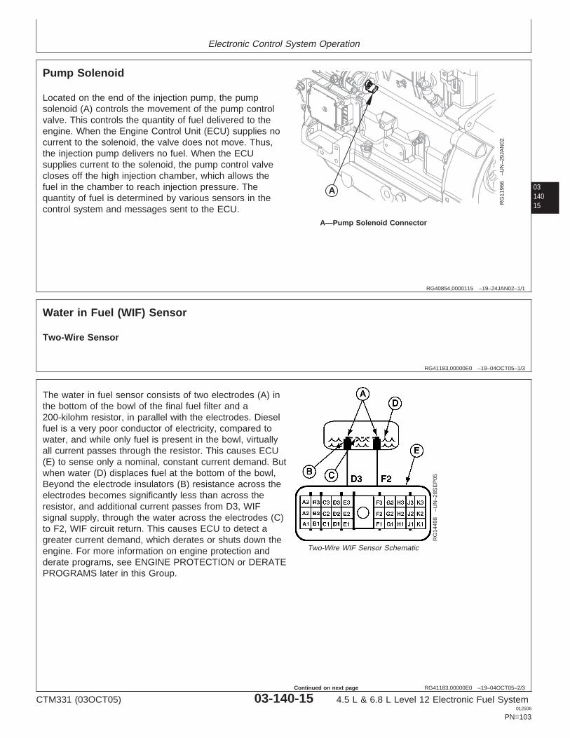
Electronic Control System Operation
0314015
RG40854,0000115 –19–24JAN02–1/1
Pump Solenoid
A
RG
1196
6–U
N–2
9JA
N02
A—Pump Solenoid Connector
Located on the end of the injection pump, the pumpsolenoid (A) controls the movement of the pump controlvalve. This controls the quantity of fuel delivered to theengine. When the Engine Control Unit (ECU) supplies nocurrent to the solenoid, the valve does not move. Thus,the injection pump delivers no fuel. When the ECUsupplies current to the solenoid, the pump control valvecloses off the high injection chamber, which allows thefuel in the chamber to reach injection pressure. Thequantity of fuel is determined by various sensors in thecontrol system and messages sent to the ECU.
RG41183,00000E0 –19–04OCT05–1/3
Water in Fuel (WIF) Sensor
Two-Wire Sensor
RG41183,00000E0 –19–04OCT05–2/3
RG
1449
8–U
N–2
8SE
P05
Two-Wire WIF Sensor Schematic
The water in fuel sensor consists of two electrodes (A) inthe bottom of the bowl of the final fuel filter and a200-kilohm resistor, in parallel with the electrodes. Dieselfuel is a very poor conductor of electricity, compared towater, and while only fuel is present in the bowl, virtuallyall current passes through the resistor. This causes ECU(E) to sense only a nominal, constant current demand. Butwhen water (D) displaces fuel at the bottom of the bowl,Beyond the electrode insulators (B) resistance across theelectrodes becomes significantly less than across theresistor, and additional current passes from D3, WIFsignal supply, through the water across the electrodes (C)to F2, WIF circuit return. This causes ECU to detect agreater current demand, which derates or shuts down theengine. For more information on engine protection andderate programs, see ENGINE PROTECTION or DERATEPROGRAMS later in this Group.
CTM331 (03OCT05) 03-140-15 4.5 L & 6.8 L Level 12 Electronic Fuel System012506
PN=103
Continued on next page
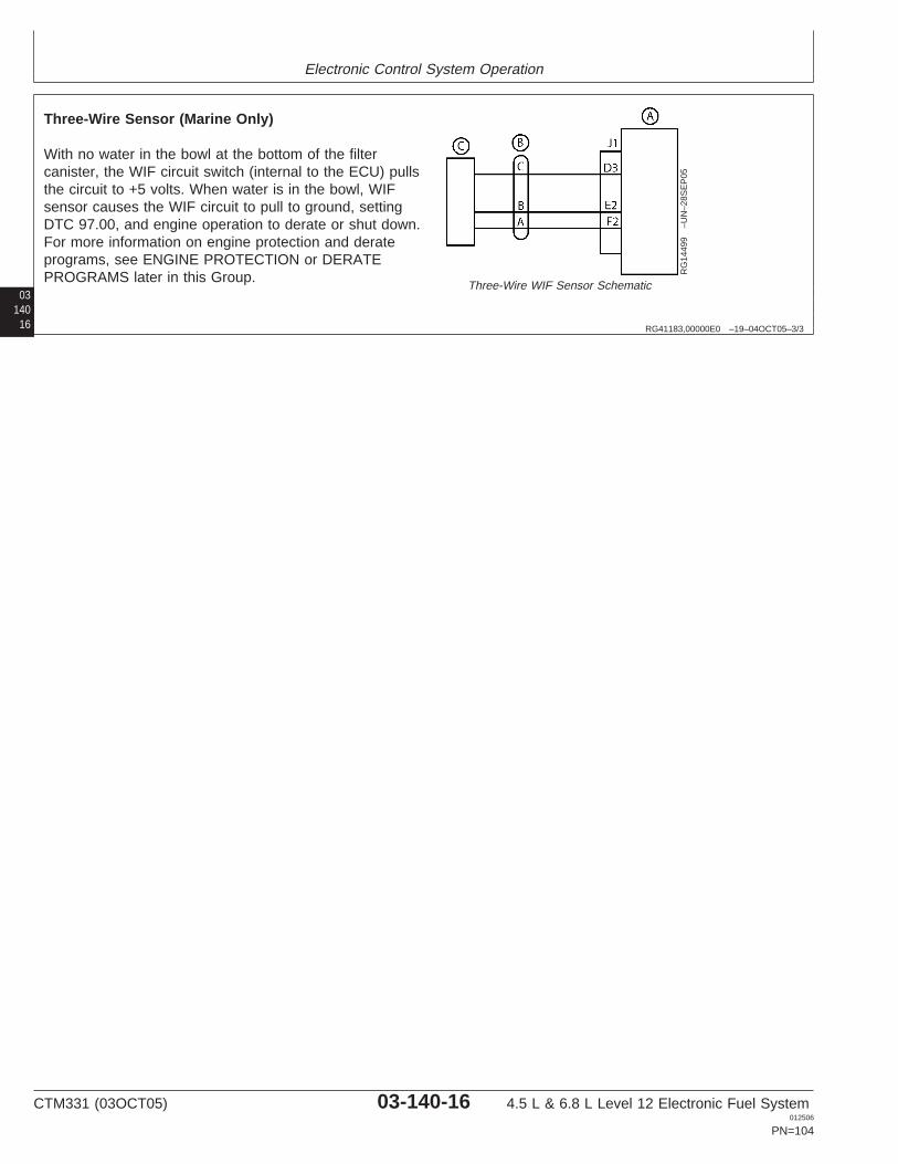
Electronic Control System Operation
03140
16 RG41183,00000E0 –19–04OCT05–3/3
RG
1449
9–U
N–2
8SE
P05
Three-Wire WIF Sensor Schematic
Three-Wire Sensor (Marine Only)
With no water in the bowl at the bottom of the filtercanister, the WIF circuit switch (internal to the ECU) pullsthe circuit to +5 volts. When water is in the bowl, WIFsensor causes the WIF circuit to pull to ground, settingDTC 97.00, and engine operation to derate or shut down.For more information on engine protection and derateprograms, see ENGINE PROTECTION or DERATEPROGRAMS later in this Group.
CTM331 (03OCT05) 03-140-16 4.5 L & 6.8 L Level 12 Electronic Fuel System012506
PN=104
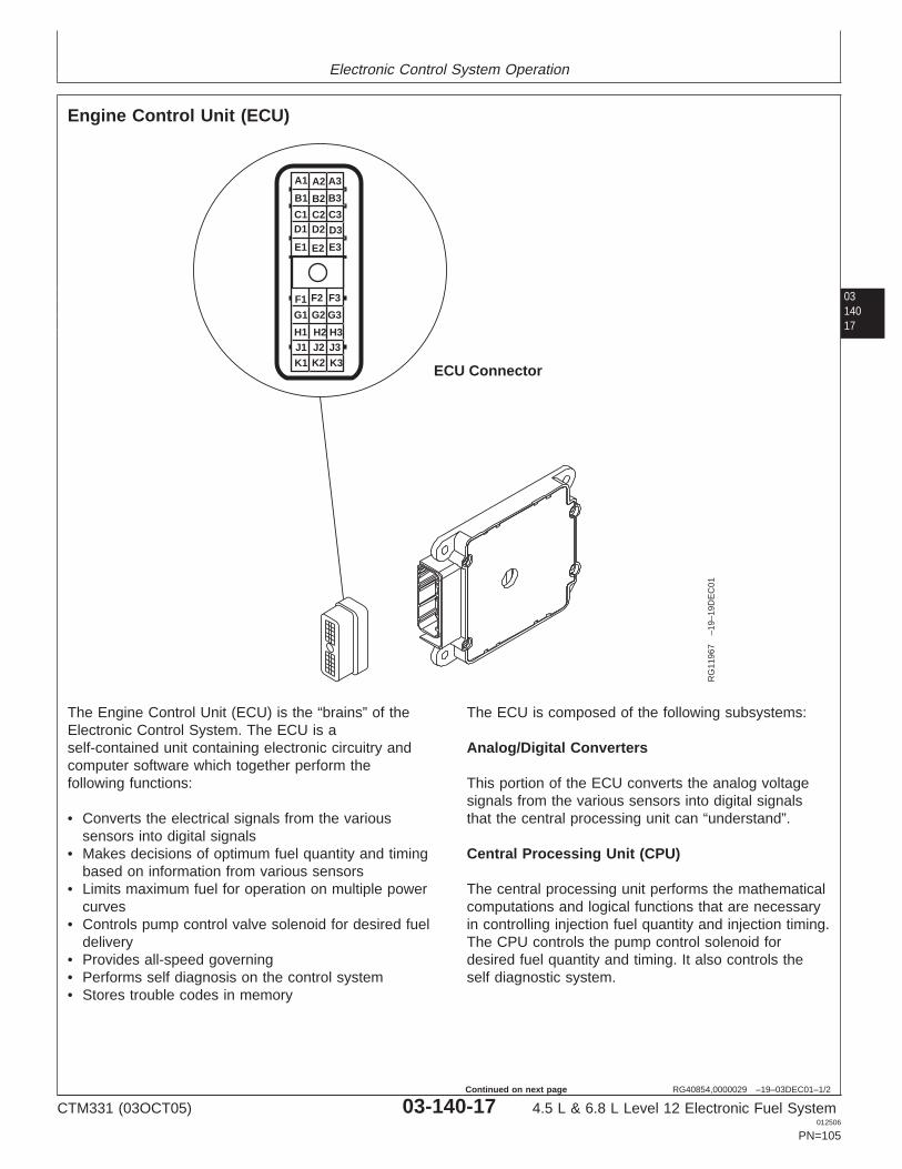
Electronic Control System Operation
0314017
RG40854,0000029 –19–03DEC01–1/2
Engine Control Unit (ECU)
ECU Connector
F3F2F1
G1
H1J1
K1
G2
H2J2
K2
G3
H3J3
K3
A3A2A1
B1
C1D1
E1
B2
C2D2
E2
B3
C3
D3
E3
RG
1196
7–1
9–19
DE
C01
The Engine Control Unit (ECU) is the “brains” of theElectronic Control System. The ECU is aself-contained unit containing electronic circuitry andcomputer software which together perform thefollowing functions:
• Converts the electrical signals from the varioussensors into digital signals
• Makes decisions of optimum fuel quantity and timingbased on information from various sensors
• Limits maximum fuel for operation on multiple powercurves
• Controls pump control valve solenoid for desired fueldelivery
• Provides all-speed governing• Performs self diagnosis on the control system• Stores trouble codes in memory
The ECU is composed of the following subsystems:
Analog/Digital Converters
This portion of the ECU converts the analog voltagesignals from the various sensors into digital signalsthat the central processing unit can “understand”.
Central Processing Unit (CPU)
The central processing unit performs the mathematicalcomputations and logical functions that are necessaryin controlling injection fuel quantity and injection timing.The CPU controls the pump control solenoid fordesired fuel quantity and timing. It also controls theself diagnostic system.
CTM331 (03OCT05) 03-140-17 4.5 L & 6.8 L Level 12 Electronic Fuel System012506
PN=105
Continued on next page
Electronic Control System Operation
03140
18
RG40854,0000029 –19–03DEC01–2/2
Memory
The ECU contains 3 different types of memory:
— Random Access Memory - RAM
The RAM is like the working desk top of the ECU.Data from the various sensors and the results ofvarious calculations are temporarily stored in RAM.Information in RAM is lost when battery voltage to theECU is removed.
— Read Only Memory - ROM
The ROM contains programmed information.Information in ROM can only be read, not changed.ROM information is retained when battery voltage isremoved.
— Electrical Erasable Programmable Read OnlyMemory - EEPROM
The EEPROM contains information programmed in atthe factory including engine specific data, andapplication data. Information in the EEPROM isretained when battery voltage is removed.
RG40854,000002A –19–03DEC01–1/1
Controller Area Network (CAN)
Controller Area Network (CAN) is used to allowcommunication between other controllers on the engine orvehicle and for connecting to diagnostic software. All ofthe controllers that are required to communicate over CANare connected together using wires forming a bus. J1939is an SAE standard that utilizes CAN.
Just about any type of information can be communicatedover the CAN Bus. This information includes partnumbers, serial numbers, engine speed, fan speed, etc.The engine also uses CAN to talk to other vehiclecontrollers. Depending on the application, variousinformation such as throttle position, derate requests,shutdown requests, and diagnostic trouble codes arecommunicated over this network. CAN also allowsdiagnostic software like and SERVICE ADVISOR tocommunicate with our engine controller. All of theinformation viewed through the software is transferred viathe CAN Bus.
SERVICE ADVISOR is a trademark of Deere & Company
CTM331 (03OCT05) 03-140-18 4.5 L & 6.8 L Level 12 Electronic Fuel System012506
PN=106
Electronic Control System Operation
0314019
RG40854,000002B –19–03DEC01–1/1
Cruise Control Operation
The ECU is available with and without the cruisecontrol function. It is an off-road cruise control thatmaintains constant engine speed under varying loadconditions. This function is especially intended for fieldapplications where an operator faces the need to turnthe vehicle around at the end of each row. This cruisecontrol allows the driver to use the throttle and/orbrake to turn the vehicle around. When ready toresume field operations, the operator brings the enginespeed above 1300 rpm and activates theCancel/Resume function again to resume cruisespeed. An internal timer gives the operator one minuteto complete the turnaround maneuver.
The cruise control has the normal functions of:
• Cruise control power “ON” or “OFF”• “Set” or “Bump Up” engine speed• “Resume” or “Bump Down” engine speed• Vehicle brake or clutch pedal to disengage cruise
control
On 12 volt ECUs, the engine speed can be set fromtwo different locations. The primary location wouldnormally be in the cab of the vehicle and is used to seta constant engine speed while the vehicle is beingdriven. The secondary cruise control is normally usedin a location that provides PTO speed control and isused with the engine in “neutral” or out of gear. Bothlocations have the normal cruise control functions.
RG40854,000002C –19–03DEC01–1/1
Intake Air Heater Operation
An optional function not included in all ECUs, theintake air heater is used to increase intake manifold airtemperature to improve cold starting. When theoperator turns the key from “OFF” to “ON”, the ECUuses the fuel temperature sensor to determine enginetemperature and ambient air temperature, turns on the“Air Heater Indicator” light on the dash, and energizesthe air heater relay.
The air heater relay will in turn energize the air heatercoils located in the intake manifold. The ECU will keepthe air heater relay energized for an amount of timethat is determined by the measured temperatures.When the ECU has determined that the preheat time is
adequate, it will turn off the “Air Heater Indicator” lightand de-energize the air heater relay. If the operatorturns the ignition from “ON” to “START” at this time,the engine will crank and start.
If the operator turns the key from “START” to “ON”without waiting for the “Air Heater Indicator” light toturn off, the ECU will de-energize the air heater relayand a key-off/key-on cycle is required beforepreheating is allowed again.
Anytime the engine cranks but does not start, akey-off/key-on cycle will be required before preheatingis allowed again.
CTM331 (03OCT05) 03-140-19 4.5 L & 6.8 L Level 12 Electronic Fuel System012506
PN=107
Electronic Control System Operation
03140
20
RG40854,000002D –19–04DEC01–1/1
Engine Protection
Engine protection is necessary to prevent damage toan engine. There are three different engine protectionprograms available in Engine Control Units (ECUs):
• No Protection — The ECU does not have thesoftware to derate or shut the engine down. It is theresponsibility of the operator to react to warninglight(s) on their application. Derating or shutting theengine down may be necessary depending on theDiagnostic Trouble Code (DTC) that is set. Refer tothe operator’s manual to identify this information fora given application.
• Engine Protection WITHOUT Shutdown — TheECU has the capability to derate an engine. It is theresponsibility of the operator to react to warninglight(s) on their application to identify if it isnecessary to shut the engine down. Refer to theoperator’s manual to retrieve this information for agiven application.
• Engine Protection with Shutdown— The ECU willderate the engine for given DTCs. If a DTC that
requires shutdown is set, the ECU will severelyderate the engine and shut the engine down in 30seconds. If the problem is corrected within the 30second delay period, the power will increase at aparticular rate until full power is reached.
Shutdown Override Feature
NOTE: Holding the shutdown override switchcontinuously “ON” will not reset the 30 secondtimer.
The engine protection shutdowns can be overriddenfor 30 seconds at a time. This can be used to move avehicle to a safe location. Each time the switch ispushed, the shutdown timer is reset to 30 seconds,and the engine will run in a derated power mode. SeeAPPLICATION SPECIFICATIONS in Section 06,Group 210 of this manual for engine protectionfeatures on different sensors on your application.
RG40854,000002F –19–04DEC01–1/1
Derate Programs
The Electronic Control Unit (ECU) will derate theamount of fuel that is delivered to the engine whensensor inputs exceed normal operating ranges. ADiagnostic Trouble Code (DTC) always accompanies a
fuel derate. See APPLICATION SPECIFICATIONS inSection 06, Group 210 of this manual for sensorderate specifications on your application.
CTM331 (03OCT05) 03-140-20 4.5 L & 6.8 L Level 12 Electronic Fuel System012506
PN=108
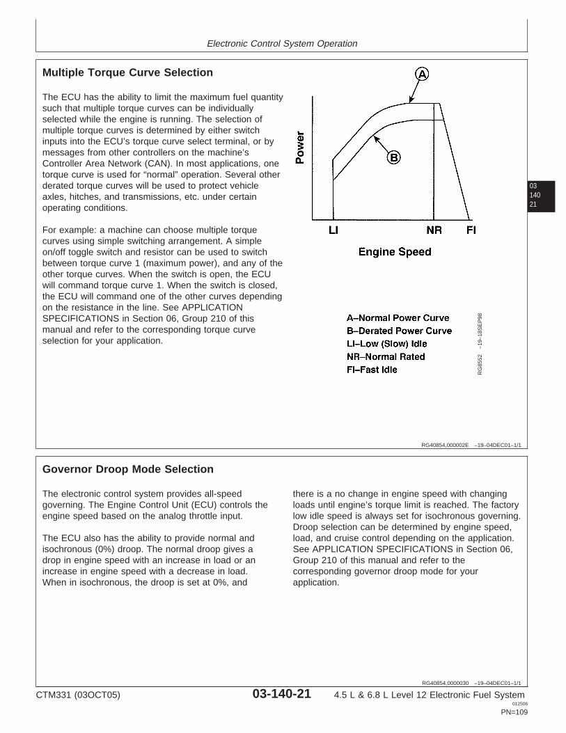
Electronic Control System Operation
0314021
RG40854,000002E –19–04DEC01–1/1
Multiple Torque Curve Selection
RG
8552
–19–
18S
EP
98
The ECU has the ability to limit the maximum fuel quantitysuch that multiple torque curves can be individuallyselected while the engine is running. The selection ofmultiple torque curves is determined by either switchinputs into the ECU’s torque curve select terminal, or bymessages from other controllers on the machine’sController Area Network (CAN). In most applications, onetorque curve is used for “normal” operation. Several otherderated torque curves will be used to protect vehicleaxles, hitches, and transmissions, etc. under certainoperating conditions.
For example: a machine can choose multiple torquecurves using simple switching arrangement. A simpleon/off toggle switch and resistor can be used to switchbetween torque curve 1 (maximum power), and any of theother torque curves. When the switch is open, the ECUwill command torque curve 1. When the switch is closed,the ECU will command one of the other curves dependingon the resistance in the line. See APPLICATIONSPECIFICATIONS in Section 06, Group 210 of thismanual and refer to the corresponding torque curveselection for your application.
RG40854,0000030 –19–04DEC01–1/1
Governor Droop Mode Selection
The electronic control system provides all-speedgoverning. The Engine Control Unit (ECU) controls theengine speed based on the analog throttle input.
The ECU also has the ability to provide normal andisochronous (0%) droop. The normal droop gives adrop in engine speed with an increase in load or anincrease in engine speed with a decrease in load.When in isochronous, the droop is set at 0%, and
there is a no change in engine speed with changingloads until engine’s torque limit is reached. The factorylow idle speed is always set for isochronous governing.Droop selection can be determined by engine speed,load, and cruise control depending on the application.See APPLICATION SPECIFICATIONS in Section 06,Group 210 of this manual and refer to thecorresponding governor droop mode for yourapplication.
CTM331 (03OCT05) 03-140-21 4.5 L & 6.8 L Level 12 Electronic Fuel System012506
PN=109
Electronic Control System Operation
03140
22
RG,RG34710,1540 –19–30SEP97–1/2
Engine Control Unit (ECU) Self-Diagnosis
The Engine Control Unit (ECU) has the ability to detectproblems internally and in the electronic controlsystem. This includes determining if any sensor inputvoltages are too high or too low. If the ECU detects aproblem with the electronic control system, aDiagnostic Trouble Code (DTC) specific to the failedsystem will be stored in the ECU’s memory.
There are two types of DTCs:
• Active• Stored
Active DTCs indicate that the failure is occurring.These type of failures are sometimes called “hard”failures.
Stored DTCs indicate that a failure has occurred in thepast, but is not currently occurring. This type of DTCcan be caused by an “intermittent” failure. These couldbe problems such as a bad connection or a wireintermittently shorting to ground.
There are several different methods for displaying bothstored and active DTCs from the ECU.
NOTE: If SERVICE ADVISOR is used to read asensor voltage and calculated value, and thereis an active DTC for that sensor, the calculatedvalue for that sensor will be the “limp home”value and the voltage will be the actual sensorvoltage. Use the voltage during diagnosticsunless otherwise directed by a diagnosticchart.
There are several different methods of displaying bothstored and active DTCs from the ECU.
SPN/FMI CODES
SPN/FMI codes are written from the SAE J1939standard as a two part code. The first part is called theSuspect Parameter Number (SPN). Typically, itcontains between 2 and 4 digits. The SPN identifiesthe system or the component that has the failure; forexample SPN 110 indicates a failure in the enginecoolant temperature circuit. The second part of thecode is called the Failure Mode Identifier (FMI) code.The FMI contains 2 digits. The FMI identifies the typeof failure that has occurred; for example FMI 3indicates value above normal. In order to determinethe exact failure, both the SPN and FMI are required.Combining SPN 110 with FMI 3 yields engine coolanttemperature input voltage high.
On all applications with the Level 12 Engine ControlUnit (ECU), the ECU transmits SPN/FMI codes overthe Controller Area Network (CAN). This allows forservice tools such as SERVICE ADVISOR and theDiagnostic Gauge to display active and stored DTCs.When using SERVICE ADVISOR the codes will bedisplayed in a 000000.00 format. For example, SPN110 FMI 3 will be displayed as 000110.03.
OTHER CODES
If codes are not displayed as SPN/FMI or as 2-digitcodes, there may be another format that theapplication is using. For example on someapplications, the code F455 is displayed for enginecoolant temperature input voltage high. This may beseen on some applications within SERVICEADVISOR. In this manual, it is necessary to convertthis format of code into an SPN/FMI code to ensurethat the correct diagnostic procedure is followed. SeeLISTING OF DIAGNOSTIC TROUBLE CODES(DTCS) ON ECU
WARNING LAMP
SERVICE ADVISOR is a trademark of Deere & CompanySERVICE ADVISOR
CTM331 (03OCT05) 03-140-22 4.5 L & 6.8 L Level 12 Electronic Fuel System012506
PN=110
Continued on next page
Electronic Control System Operation
0314023RG,RG34710,1540 –19–30SEP97–2/2
On some applications, there is a warning lamp that isused when a code becomes active. Typically, a solidlight indicates that the ECU is taking extrememeasures to protect the engine, and a blinking lightindicates that the ECU has detected a fault and engineperformance may be affected. Refer to Operator’sManual for a given application for more detailedinformation.
CLEARING STORED DTCS
Stored DTCs can be cleared through SERVICEADVISOR. Refer to the vehicle machine manual orsee CLEARING STORED DTCS ON DIAGNOSTICGAUGE in Group 160 later in this manual to determinehow to clear the code reader.
SERVICE ADVISOR is a trademark of Deere & Company
CTM331 (03OCT05) 03-140-23 4.5 L & 6.8 L Level 12 Electronic Fuel System012506
PN=111
Electronic Control System Operation
03140
24
CTM331 (03OCT05) 03-140-24 4.5 L & 6.8 L Level 12 Electronic Fuel System012506
PN=112
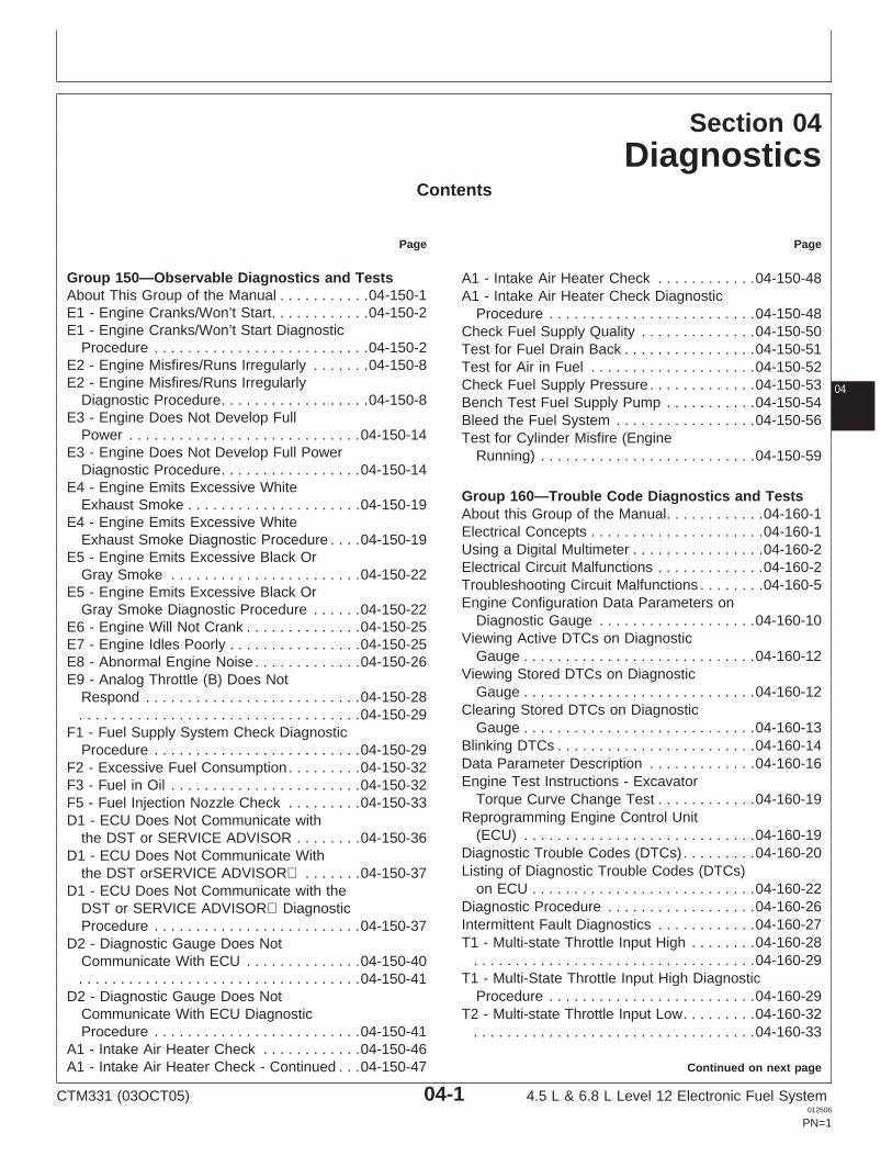
Section 04Diagnostics
Contents
Page Page
Group 150—Observable Diagnostics and Tests A1 - Intake Air Heater Check . . . . . . . . . . . .04-150-48About This Group of the Manual . . . . . . . . . . .04-150-1 A1 - Intake Air Heater Check DiagnosticE1 - Engine Cranks/Won’t Start. . . . . . . . . . . .04-150-2 Procedure . . . . . . . . . . . . . . . . . . . . . . . . .04-150-48E1 - Engine Cranks/Won’t Start Diagnostic Check Fuel Supply Quality . . . . . . . . . . . . . .04-150-50
Procedure . . . . . . . . . . . . . . . . . . . . . . . . . .04-150-2 Test for Fuel Drain Back . . . . . . . . . . . . . . . .04-150-51E2 - Engine Misfires/Runs Irregularly . . . . . . .04-150-8 Test for Air in Fuel . . . . . . . . . . . . . . . . . . . .04-150-52E2 - Engine Misfires/Runs Irregularly Check Fuel Supply Pressure . . . . . . . . . . . . .04-150-53 04
Diagnostic Procedure. . . . . . . . . . . . . . . . . .04-150-8 Bench Test Fuel Supply Pump . . . . . . . . . . .04-150-54E3 - Engine Does Not Develop Full Bleed the Fuel System . . . . . . . . . . . . . . . . .04-150-56
Power . . . . . . . . . . . . . . . . . . . . . . . . . . . .04-150-14 Test for Cylinder Misfire (EngineE3 - Engine Does Not Develop Full Power Running) . . . . . . . . . . . . . . . . . . . . . . . . . .04-150-59
Diagnostic Procedure. . . . . . . . . . . . . . . . .04-150-14E4 - Engine Emits Excessive White
Group 160—Trouble Code Diagnostics and TestsExhaust Smoke . . . . . . . . . . . . . . . . . . . . .04-150-19
About this Group of the Manual. . . . . . . . . . . .04-160-1E4 - Engine Emits Excessive WhiteElectrical Concepts . . . . . . . . . . . . . . . . . . . . .04-160-1Exhaust Smoke Diagnostic Procedure . . . .04-150-19Using a Digital Multimeter . . . . . . . . . . . . . . . .04-160-2E5 - Engine Emits Excessive Black OrElectrical Circuit Malfunctions . . . . . . . . . . . . .04-160-2Gray Smoke . . . . . . . . . . . . . . . . . . . . . . .04-150-22Troubleshooting Circuit Malfunctions . . . . . . . .04-160-5E5 - Engine Emits Excessive Black OrEngine Configuration Data Parameters onGray Smoke Diagnostic Procedure . . . . . .04-150-22
Diagnostic Gauge . . . . . . . . . . . . . . . . . . .04-160-10E6 - Engine Will Not Crank . . . . . . . . . . . . . .04-150-25Viewing Active DTCs on DiagnosticE7 - Engine Idles Poorly . . . . . . . . . . . . . . . .04-150-25
Gauge . . . . . . . . . . . . . . . . . . . . . . . . . . . .04-160-12E8 - Abnormal Engine Noise . . . . . . . . . . . . .04-150-26Viewing Stored DTCs on DiagnosticE9 - Analog Throttle (B) Does Not
Gauge . . . . . . . . . . . . . . . . . . . . . . . . . . . .04-160-12Respond . . . . . . . . . . . . . . . . . . . . . . . . . .04-150-28Clearing Stored DTCs on Diagnostic. . . . . . . . . . . . . . . . . . . . . . . . . . . . . . . . . .04-150-29
Gauge . . . . . . . . . . . . . . . . . . . . . . . . . . . .04-160-13F1 - Fuel Supply System Check DiagnosticBlinking DTCs . . . . . . . . . . . . . . . . . . . . . . . .04-160-14Procedure . . . . . . . . . . . . . . . . . . . . . . . . .04-150-29Data Parameter Description . . . . . . . . . . . . .04-160-16F2 - Excessive Fuel Consumption. . . . . . . . .04-150-32Engine Test Instructions - ExcavatorF3 - Fuel in Oil . . . . . . . . . . . . . . . . . . . . . . .04-150-32
Torque Curve Change Test . . . . . . . . . . . .04-160-19F5 - Fuel Injection Nozzle Check . . . . . . . . .04-150-33Reprogramming Engine Control UnitD1 - ECU Does Not Communicate with
(ECU) . . . . . . . . . . . . . . . . . . . . . . . . . . . .04-160-19the DST or SERVICE ADVISOR . . . . . . . .04-150-36Diagnostic Trouble Codes (DTCs) . . . . . . . . .04-160-20D1 - ECU Does Not Communicate WithListing of Diagnostic Trouble Codes (DTCs)the DST orSERVICE ADVISOR . . . . . . .04-150-37
on ECU . . . . . . . . . . . . . . . . . . . . . . . . . . .04-160-22D1 - ECU Does Not Communicate with theDiagnostic Procedure . . . . . . . . . . . . . . . . . .04-160-26DST or SERVICE ADVISOR DiagnosticIntermittent Fault Diagnostics . . . . . . . . . . . .04-160-27Procedure . . . . . . . . . . . . . . . . . . . . . . . . .04-150-37T1 - Multi-state Throttle Input High . . . . . . . .04-160-28D2 - Diagnostic Gauge Does Not
. . . . . . . . . . . . . . . . . . . . . . . . . . . . . . . . . .04-160-29Communicate With ECU . . . . . . . . . . . . . .04-150-40T1 - Multi-State Throttle Input High Diagnostic. . . . . . . . . . . . . . . . . . . . . . . . . . . . . . . . . .04-150-41
Procedure . . . . . . . . . . . . . . . . . . . . . . . . .04-160-29D2 - Diagnostic Gauge Does NotCommunicate With ECU Diagnostic T2 - Multi-state Throttle Input Low. . . . . . . . .04-160-32Procedure . . . . . . . . . . . . . . . . . . . . . . . . .04-150-41 . . . . . . . . . . . . . . . . . . . . . . . . . . . . . . . . . .04-160-33
A1 - Intake Air Heater Check . . . . . . . . . . . .04-150-46Continued on next pageA1 - Intake Air Heater Check - Continued . . .04-150-47
CTM331 (03OCT05) 04-1 4.5 L & 6.8 L Level 12 Electronic Fuel System012506
PN=1
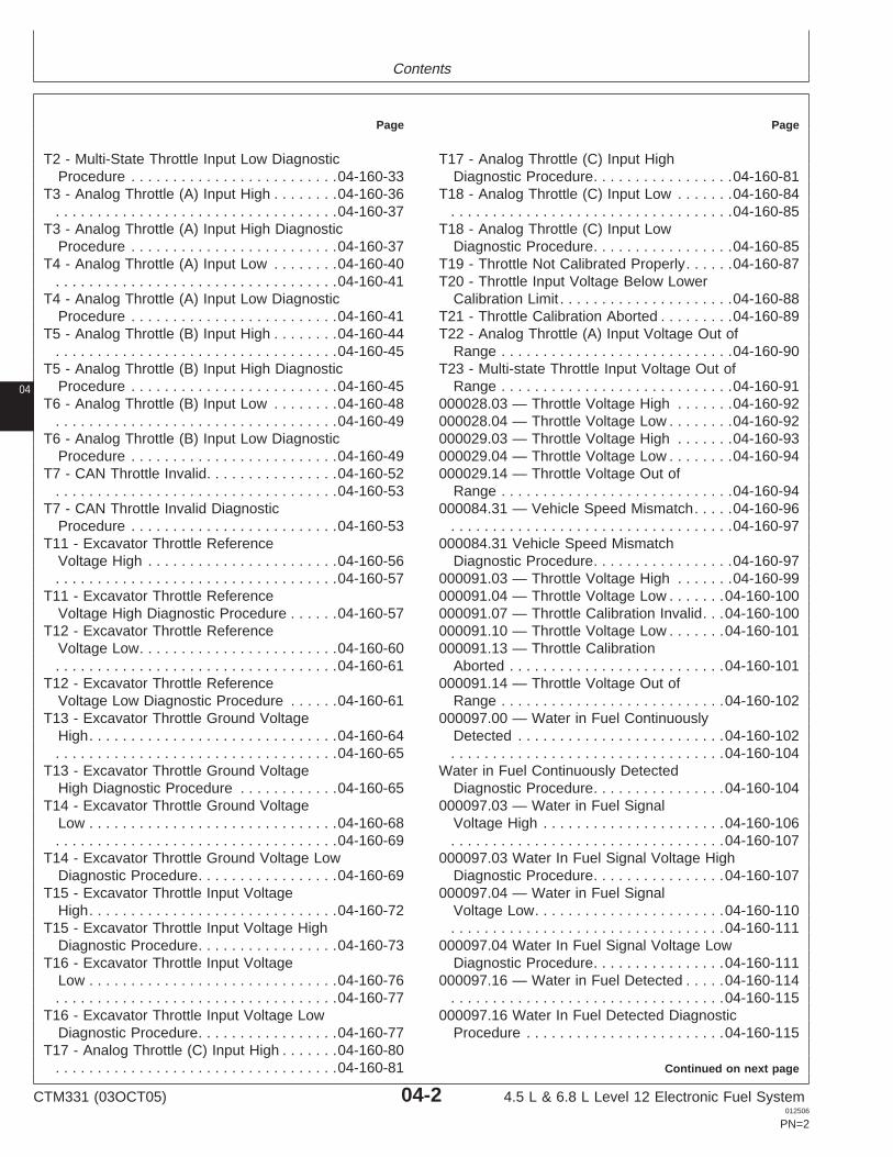
Contents
Page Page
T2 - Multi-State Throttle Input Low Diagnostic T17 - Analog Throttle (C) Input HighDiagnostic Procedure. . . . . . . . . . . . . . . . .04-160-81Procedure . . . . . . . . . . . . . . . . . . . . . . . . .04-160-33
T3 - Analog Throttle (A) Input High . . . . . . . .04-160-36 T18 - Analog Throttle (C) Input Low . . . . . . .04-160-84. . . . . . . . . . . . . . . . . . . . . . . . . . . . . . . . . .04-160-85. . . . . . . . . . . . . . . . . . . . . . . . . . . . . . . . . .04-160-37
T3 - Analog Throttle (A) Input High Diagnostic T18 - Analog Throttle (C) Input LowDiagnostic Procedure. . . . . . . . . . . . . . . . .04-160-85Procedure . . . . . . . . . . . . . . . . . . . . . . . . .04-160-37
T4 - Analog Throttle (A) Input Low . . . . . . . .04-160-40 T19 - Throttle Not Calibrated Properly. . . . . .04-160-87T20 - Throttle Input Voltage Below Lower. . . . . . . . . . . . . . . . . . . . . . . . . . . . . . . . . .04-160-41
T4 - Analog Throttle (A) Input Low Diagnostic Calibration Limit . . . . . . . . . . . . . . . . . . . . .04-160-88T21 - Throttle Calibration Aborted . . . . . . . . .04-160-89Procedure . . . . . . . . . . . . . . . . . . . . . . . . .04-160-41
T5 - Analog Throttle (B) Input High . . . . . . . .04-160-44 T22 - Analog Throttle (A) Input Voltage Out ofRange . . . . . . . . . . . . . . . . . . . . . . . . . . . .04-160-90. . . . . . . . . . . . . . . . . . . . . . . . . . . . . . . . . .04-160-45
T5 - Analog Throttle (B) Input High Diagnostic T23 - Multi-state Throttle Input Voltage Out ofRange . . . . . . . . . . . . . . . . . . . . . . . . . . . .04-160-91Procedure . . . . . . . . . . . . . . . . . . . . . . . . .04-160-45
T6 - Analog Throttle (B) Input Low . . . . . . . .04-160-48 000028.03 — Throttle Voltage High . . . . . . .04-160-92000028.04 — Throttle Voltage Low . . . . . . . .04-160-92. . . . . . . . . . . . . . . . . . . . . . . . . . . . . . . . . .04-160-49
T6 - Analog Throttle (B) Input Low Diagnostic 000029.03 — Throttle Voltage High . . . . . . .04-160-93
04
Procedure . . . . . . . . . . . . . . . . . . . . . . . . .04-160-49 000029.04 — Throttle Voltage Low . . . . . . . .04-160-94000029.14 — Throttle Voltage Out ofT7 - CAN Throttle Invalid. . . . . . . . . . . . . . . .04-160-52
. . . . . . . . . . . . . . . . . . . . . . . . . . . . . . . . . .04-160-53 Range . . . . . . . . . . . . . . . . . . . . . . . . . . . .04-160-94000084.31 — Vehicle Speed Mismatch. . . . .04-160-96T7 - CAN Throttle Invalid Diagnostic
Procedure . . . . . . . . . . . . . . . . . . . . . . . . .04-160-53 . . . . . . . . . . . . . . . . . . . . . . . . . . . . . . . . . .04-160-97000084.31 Vehicle Speed MismatchT11 - Excavator Throttle Reference
Voltage High . . . . . . . . . . . . . . . . . . . . . . .04-160-56 Diagnostic Procedure. . . . . . . . . . . . . . . . .04-160-97000091.03 — Throttle Voltage High . . . . . . .04-160-99. . . . . . . . . . . . . . . . . . . . . . . . . . . . . . . . . .04-160-57
T11 - Excavator Throttle Reference 000091.04 — Throttle Voltage Low . . . . . . .04-160-100000091.07 — Throttle Calibration Invalid. . .04-160-100Voltage High Diagnostic Procedure . . . . . .04-160-57
T12 - Excavator Throttle Reference 000091.10 — Throttle Voltage Low . . . . . . .04-160-101000091.13 — Throttle CalibrationVoltage Low. . . . . . . . . . . . . . . . . . . . . . . .04-160-60
. . . . . . . . . . . . . . . . . . . . . . . . . . . . . . . . . .04-160-61 Aborted . . . . . . . . . . . . . . . . . . . . . . . . . .04-160-101000091.14 — Throttle Voltage Out ofT12 - Excavator Throttle Reference
Voltage Low Diagnostic Procedure . . . . . .04-160-61 Range . . . . . . . . . . . . . . . . . . . . . . . . . . .04-160-102000097.00 — Water in Fuel ContinuouslyT13 - Excavator Throttle Ground Voltage
High. . . . . . . . . . . . . . . . . . . . . . . . . . . . . .04-160-64 Detected . . . . . . . . . . . . . . . . . . . . . . . . .04-160-102. . . . . . . . . . . . . . . . . . . . . . . . . . . . . . . . .04-160-104. . . . . . . . . . . . . . . . . . . . . . . . . . . . . . . . . .04-160-65
T13 - Excavator Throttle Ground Voltage Water in Fuel Continuously DetectedDiagnostic Procedure. . . . . . . . . . . . . . . .04-160-104High Diagnostic Procedure . . . . . . . . . . . .04-160-65
T14 - Excavator Throttle Ground Voltage 000097.03 — Water in Fuel SignalVoltage High . . . . . . . . . . . . . . . . . . . . . .04-160-106Low . . . . . . . . . . . . . . . . . . . . . . . . . . . . . .04-160-68
. . . . . . . . . . . . . . . . . . . . . . . . . . . . . . . . . .04-160-69 . . . . . . . . . . . . . . . . . . . . . . . . . . . . . . . . .04-160-107000097.03 Water In Fuel Signal Voltage HighT14 - Excavator Throttle Ground Voltage Low
Diagnostic Procedure. . . . . . . . . . . . . . . . .04-160-69 Diagnostic Procedure. . . . . . . . . . . . . . . .04-160-107000097.04 — Water in Fuel SignalT15 - Excavator Throttle Input Voltage
High. . . . . . . . . . . . . . . . . . . . . . . . . . . . . .04-160-72 Voltage Low. . . . . . . . . . . . . . . . . . . . . . .04-160-110. . . . . . . . . . . . . . . . . . . . . . . . . . . . . . . . .04-160-111T15 - Excavator Throttle Input Voltage High
Diagnostic Procedure. . . . . . . . . . . . . . . . .04-160-73 000097.04 Water In Fuel Signal Voltage LowDiagnostic Procedure. . . . . . . . . . . . . . . .04-160-111T16 - Excavator Throttle Input Voltage
Low . . . . . . . . . . . . . . . . . . . . . . . . . . . . . .04-160-76 000097.16 — Water in Fuel Detected . . . . .04-160-114. . . . . . . . . . . . . . . . . . . . . . . . . . . . . . . . .04-160-115. . . . . . . . . . . . . . . . . . . . . . . . . . . . . . . . . .04-160-77
T16 - Excavator Throttle Input Voltage Low 000097.16 Water In Fuel Detected DiagnosticProcedure . . . . . . . . . . . . . . . . . . . . . . . .04-160-115Diagnostic Procedure. . . . . . . . . . . . . . . . .04-160-77
T17 - Analog Throttle (C) Input High . . . . . . .04-160-80Continued on next page. . . . . . . . . . . . . . . . . . . . . . . . . . . . . . . . . .04-160-81
CTM331 (03OCT05) 04-2 4.5 L & 6.8 L Level 12 Electronic Fuel System012506
PN=2
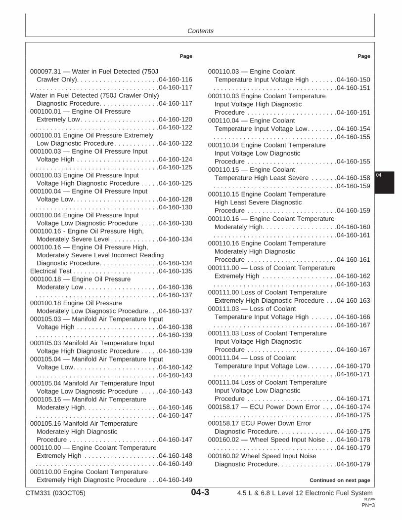
Contents
Page Page
000097.31 — Water in Fuel Detected (750J 000110.03 — Engine CoolantCrawler Only). . . . . . . . . . . . . . . . . . . . . .04-160-116 Temperature Input Voltage High . . . . . . .04-160-150. . . . . . . . . . . . . . . . . . . . . . . . . . . . . . . . .04-160-117 . . . . . . . . . . . . . . . . . . . . . . . . . . . . . . . . .04-160-151
Water in Fuel Detected (750J Crawler Only) 000110.03 Engine Coolant TemperatureDiagnostic Procedure. . . . . . . . . . . . . . . .04-160-117 Input Voltage High Diagnostic
000100.01 — Engine Oil Pressure Procedure . . . . . . . . . . . . . . . . . . . . . . . .04-160-151Extremely Low . . . . . . . . . . . . . . . . . . . . .04-160-120 000110.04 — Engine Coolant. . . . . . . . . . . . . . . . . . . . . . . . . . . . . . . . .04-160-122 Temperature Input Voltage Low. . . . . . . .04-160-154
000100.01 Engine Oil Pressure Extremely . . . . . . . . . . . . . . . . . . . . . . . . . . . . . . . . .04-160-155Low Diagnostic Procedure . . . . . . . . . . . .04-160-122 000110.04 Engine Coolant Temperature
000100.03 — Engine Oil Pressure Input Input Voltage Low DiagnosticVoltage High . . . . . . . . . . . . . . . . . . . . . .04-160-124 Procedure . . . . . . . . . . . . . . . . . . . . . . . .04-160-155. . . . . . . . . . . . . . . . . . . . . . . . . . . . . . . . .04-160-125 000110.15 — Engine Coolant
04000100.03 Engine Oil Pressure Input Temperature High Least Severe . . . . . . .04-160-158Voltage High Diagnostic Procedure . . . . .04-160-125 . . . . . . . . . . . . . . . . . . . . . . . . . . . . . . . . .04-160-159
000100.04 — Engine Oil Pressure Input 000110.15 Engine Coolant TemperatureVoltage Low. . . . . . . . . . . . . . . . . . . . . . .04-160-128 High Least Severe Diagnostic. . . . . . . . . . . . . . . . . . . . . . . . . . . . . . . . .04-160-130 Procedure . . . . . . . . . . . . . . . . . . . . . . . .04-160-159
000100.04 Engine Oil Pressure Input 000110.16 — Engine Coolant TemperatureVoltage Low Diagnostic Procedure . . . . .04-160-130 Moderately High. . . . . . . . . . . . . . . . . . . .04-160-160
000100.16 - Engine Oil Pressure High,. . . . . . . . . . . . . . . . . . . . . . . . . . . . . . . . .04-160-161
Moderately Severe Level . . . . . . . . . . . . .04-160-134000110.16 Engine Coolant Temperature
000100.16 — Engine Oil Pressure High,Moderately High DiagnosticModerately Severe Level Incorrect ReadingProcedure . . . . . . . . . . . . . . . . . . . . . . . .04-160-161Diagnostic Procedure. . . . . . . . . . . . . . . .04-160-134
000111.00 — Loss of Coolant TemperatureElectrical Test . . . . . . . . . . . . . . . . . . . . . . .04-160-135Extremely High . . . . . . . . . . . . . . . . . . . .04-160-162000100.18 — Engine Oil Pressure. . . . . . . . . . . . . . . . . . . . . . . . . . . . . . . . .04-160-163Moderately Low . . . . . . . . . . . . . . . . . . . .04-160-136
000111.00 Loss of Coolant Temperature. . . . . . . . . . . . . . . . . . . . . . . . . . . . . . . . .04-160-137Extremely High Diagnostic Procedure . . .04-160-163000100.18 Engine Oil Pressure
000111.03 — Loss of CoolantModerately Low Diagnostic Procedure . . .04-160-137Temperature Input Voltage High . . . . . . .04-160-166000105.03 — Manifold Air Temperature Input. . . . . . . . . . . . . . . . . . . . . . . . . . . . . . . . .04-160-167Voltage High . . . . . . . . . . . . . . . . . . . . . .04-160-138
000111.03 Loss of Coolant Temperature. . . . . . . . . . . . . . . . . . . . . . . . . . . . . . . . .04-160-139Input Voltage High Diagnostic000105.03 Manifold Air Temperature InputProcedure . . . . . . . . . . . . . . . . . . . . . . . .04-160-167Voltage High Diagnostic Procedure . . . . .04-160-139
000111.04 — Loss of Coolant000105.04 — Manifold Air Temperature InputTemperature Input Voltage Low. . . . . . . .04-160-170Voltage Low. . . . . . . . . . . . . . . . . . . . . . .04-160-142. . . . . . . . . . . . . . . . . . . . . . . . . . . . . . . . .04-160-171. . . . . . . . . . . . . . . . . . . . . . . . . . . . . . . . .04-160-143
000111.04 Loss of Coolant Temperature000105.04 Manifold Air Temperature InputInput Voltage Low DiagnosticVoltage Low Diagnostic Procedure . . . . .04-160-143Procedure . . . . . . . . . . . . . . . . . . . . . . . .04-160-171000105.16 — Manifold Air Temperature
000158.17 — ECU Power Down Error . . . .04-160-174Moderately High. . . . . . . . . . . . . . . . . . . .04-160-146. . . . . . . . . . . . . . . . . . . . . . . . . . . . . . . . .04-160-175. . . . . . . . . . . . . . . . . . . . . . . . . . . . . . . . .04-160-147
000158.17 ECU Power Down Error000105.16 Manifold Air TemperatureDiagnostic Procedure. . . . . . . . . . . . . . . .04-160-175Moderately High Diagnostic
Procedure . . . . . . . . . . . . . . . . . . . . . . . .04-160-147 000160.02 — Wheel Speed Input Noise . . .04-160-178000110.00 — Engine Coolant Temperature . . . . . . . . . . . . . . . . . . . . . . . . . . . . . . . . .04-160-179
Extremely High . . . . . . . . . . . . . . . . . . . .04-160-148 000160.02 Wheel Speed Input Noise. . . . . . . . . . . . . . . . . . . . . . . . . . . . . . . . .04-160-149 Diagnostic Procedure. . . . . . . . . . . . . . . .04-160-179
000110.00 Engine Coolant TemperatureContinued on next pageExtremely High Diagnostic Procedure . . .04-160-149
CTM331 (03OCT05) 04-3 4.5 L & 6.8 L Level 12 Electronic Fuel System012506
PN=3
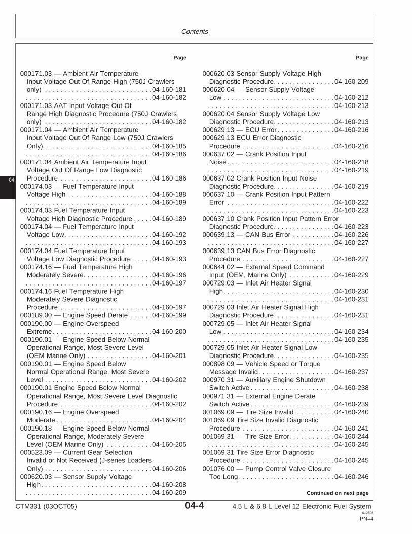
Contents
Page Page
000171.03 — Ambient Air Temperature 000620.03 Sensor Supply Voltage HighDiagnostic Procedure. . . . . . . . . . . . . . . .04-160-209Input Voltage Out Of Range High (750J Crawlers
only) . . . . . . . . . . . . . . . . . . . . . . . . . . . .04-160-181 000620.04 — Sensor Supply VoltageLow . . . . . . . . . . . . . . . . . . . . . . . . . . . . .04-160-212. . . . . . . . . . . . . . . . . . . . . . . . . . . . . . . . .04-160-182
000171.03 AAT Input Voltage Out Of . . . . . . . . . . . . . . . . . . . . . . . . . . . . . . . . .04-160-213000620.04 Sensor Supply Voltage LowRange High Diagnostic Procedure (750J Crawlers
only) . . . . . . . . . . . . . . . . . . . . . . . . . . . .04-160-182 Diagnostic Procedure. . . . . . . . . . . . . . . .04-160-213000629.13 — ECU Error . . . . . . . . . . . . . . .04-160-216000171.04 — Ambient Air Temperature
Input Voltage Out Of Range Low (750J Crawlers 000629.13 ECU Error DiagnosticProcedure . . . . . . . . . . . . . . . . . . . . . . . .04-160-216Only) . . . . . . . . . . . . . . . . . . . . . . . . . . . .04-160-185
. . . . . . . . . . . . . . . . . . . . . . . . . . . . . . . . .04-160-186 000637.02 — Crank Position InputNoise . . . . . . . . . . . . . . . . . . . . . . . . . . . .04-160-218000171.04 Ambient Air Temperature Input
Voltage Out Of Range Low Diagnostic . . . . . . . . . . . . . . . . . . . . . . . . . . . . . . . . .04-160-219000637.02 Crank Position Input NoiseProcedure . . . . . . . . . . . . . . . . . . . . . . . .04-160-186
000174.03 — Fuel Temperature Input Diagnostic Procedure. . . . . . . . . . . . . . . .04-160-219000637.10 — Crank Position Input PatternVoltage High . . . . . . . . . . . . . . . . . . . . . .04-160-188
. . . . . . . . . . . . . . . . . . . . . . . . . . . . . . . . .04-160-189 Error . . . . . . . . . . . . . . . . . . . . . . . . . . . .04-160-222
04
000174.03 Fuel Temperature Input . . . . . . . . . . . . . . . . . . . . . . . . . . . . . . . . .04-160-223000637.10 Crank Position Input Pattern ErrorVoltage High Diagnostic Procedure . . . . .04-160-189
000174.04 — Fuel Temperature Input Diagnostic Procedure. . . . . . . . . . . . . . . .04-160-223000639.13 — CAN Bus Error . . . . . . . . . . .04-160-226Voltage Low. . . . . . . . . . . . . . . . . . . . . . .04-160-192
. . . . . . . . . . . . . . . . . . . . . . . . . . . . . . . . .04-160-193 . . . . . . . . . . . . . . . . . . . . . . . . . . . . . . . . .04-160-227000639.13 CAN Bus Error Diagnostic000174.04 Fuel Temperature Input
Voltage Low Diagnostic Procedure . . . . .04-160-193 Procedure . . . . . . . . . . . . . . . . . . . . . . . .04-160-227000644.02 — External Speed Command000174.16 — Fuel Temperature High
Moderately Severe. . . . . . . . . . . . . . . . . .04-160-196 Input (OEM, Marine Only) . . . . . . . . . . . .04-160-229000729.03 — Inlet Air Heater Signal. . . . . . . . . . . . . . . . . . . . . . . . . . . . . . . . .04-160-197
000174.16 Fuel Temperature High High. . . . . . . . . . . . . . . . . . . . . . . . . . . . .04-160-230. . . . . . . . . . . . . . . . . . . . . . . . . . . . . . . . .04-160-231Moderately Severe Diagnostic
Procedure . . . . . . . . . . . . . . . . . . . . . . . .04-160-197 000729.03 Inlet Air Heater Signal HighDiagnostic Procedure. . . . . . . . . . . . . . . .04-160-231000189.00 — Engine Speed Derate . . . . . .04-160-199
000190.00 — Engine Overspeed 000729.05 — Inlet Air Heater SignalLow . . . . . . . . . . . . . . . . . . . . . . . . . . . . .04-160-234Extreme . . . . . . . . . . . . . . . . . . . . . . . . . .04-160-200
000190.01 — Engine Speed Below Normal . . . . . . . . . . . . . . . . . . . . . . . . . . . . . . . . .04-160-235000729.05 Inlet Air Heater Signal LowOperational Range, Most Severe Level
(OEM Marine Only) . . . . . . . . . . . . . . . . .04-160-201 Diagnostic Procedure. . . . . . . . . . . . . . . .04-160-235000898.09 — Vehicle Speed or Torque000190.01 — Engine Speed Below
Normal Operational Range, Most Severe Message Invalid. . . . . . . . . . . . . . . . . . . .04-160-237000970.31 — Auxiliary Engine ShutdownLevel . . . . . . . . . . . . . . . . . . . . . . . . . . . .04-160-202
000190.01 Engine Speed Below Normal Switch Active . . . . . . . . . . . . . . . . . . . . . .04-160-238000971.31 — External Engine DerateOperational Range, Most Severe Level Diagnostic
Procedure . . . . . . . . . . . . . . . . . . . . . . . .04-160-202 Switch Active . . . . . . . . . . . . . . . . . . . . . .04-160-239001069.09 — Tire Size Invalid . . . . . . . . . .04-160-240000190.16 — Engine Overspeed
Moderate . . . . . . . . . . . . . . . . . . . . . . . . .04-160-204 001069.09 Tire Size Invalid DiagnosticProcedure . . . . . . . . . . . . . . . . . . . . . . . .04-160-241000190.18 — Engine Speed Below Normal
Operational Range, Moderately Severe 001069.31 — Tire Size Error. . . . . . . . . . . .04-160-244. . . . . . . . . . . . . . . . . . . . . . . . . . . . . . . . .04-160-245Level (OEM Marine Only) . . . . . . . . . . . .04-160-205
000523.09 — Current Gear Selection 001069.31 Tire Size Error DiagnosticProcedure . . . . . . . . . . . . . . . . . . . . . . . .04-160-245Invalid or Not Received (J-series Loaders
Only) . . . . . . . . . . . . . . . . . . . . . . . . . . . .04-160-206 001076.00 — Pump Control Valve ClosureToo Long . . . . . . . . . . . . . . . . . . . . . . . . .04-160-246000620.03 — Sensor Supply Voltage
High. . . . . . . . . . . . . . . . . . . . . . . . . . . . .04-160-208Continued on next page. . . . . . . . . . . . . . . . . . . . . . . . . . . . . . . . .04-160-209
CTM331 (03OCT05) 04-4 4.5 L & 6.8 L Level 12 Electronic Fuel System012506
PN=4
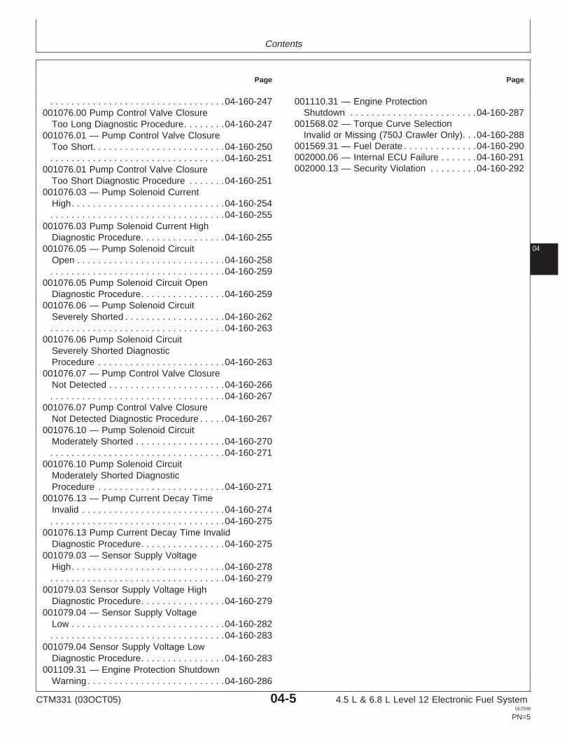
Contents
Page Page
. . . . . . . . . . . . . . . . . . . . . . . . . . . . . . . . .04-160-247 001110.31 — Engine ProtectionShutdown . . . . . . . . . . . . . . . . . . . . . . . .04-160-287001076.00 Pump Control Valve Closure
001568.02 — Torque Curve SelectionToo Long Diagnostic Procedure. . . . . . . .04-160-247Invalid or Missing (750J Crawler Only). . .04-160-288001076.01 — Pump Control Valve Closure
001569.31 — Fuel Derate . . . . . . . . . . . . . .04-160-290Too Short. . . . . . . . . . . . . . . . . . . . . . . . .04-160-250002000.06 — Internal ECU Failure . . . . . . .04-160-291. . . . . . . . . . . . . . . . . . . . . . . . . . . . . . . . .04-160-251002000.13 — Security Violation . . . . . . . . .04-160-292001076.01 Pump Control Valve Closure
Too Short Diagnostic Procedure . . . . . . .04-160-251001076.03 — Pump Solenoid Current
High. . . . . . . . . . . . . . . . . . . . . . . . . . . . .04-160-254. . . . . . . . . . . . . . . . . . . . . . . . . . . . . . . . .04-160-255
001076.03 Pump Solenoid Current HighDiagnostic Procedure. . . . . . . . . . . . . . . .04-160-255
04001076.05 — Pump Solenoid CircuitOpen . . . . . . . . . . . . . . . . . . . . . . . . . . . .04-160-258. . . . . . . . . . . . . . . . . . . . . . . . . . . . . . . . .04-160-259
001076.05 Pump Solenoid Circuit OpenDiagnostic Procedure. . . . . . . . . . . . . . . .04-160-259
001076.06 — Pump Solenoid CircuitSeverely Shorted . . . . . . . . . . . . . . . . . . .04-160-262. . . . . . . . . . . . . . . . . . . . . . . . . . . . . . . . .04-160-263
001076.06 Pump Solenoid CircuitSeverely Shorted DiagnosticProcedure . . . . . . . . . . . . . . . . . . . . . . . .04-160-263
001076.07 — Pump Control Valve ClosureNot Detected . . . . . . . . . . . . . . . . . . . . . .04-160-266. . . . . . . . . . . . . . . . . . . . . . . . . . . . . . . . .04-160-267
001076.07 Pump Control Valve ClosureNot Detected Diagnostic Procedure . . . . .04-160-267
001076.10 — Pump Solenoid CircuitModerately Shorted . . . . . . . . . . . . . . . . .04-160-270. . . . . . . . . . . . . . . . . . . . . . . . . . . . . . . . .04-160-271
001076.10 Pump Solenoid CircuitModerately Shorted DiagnosticProcedure . . . . . . . . . . . . . . . . . . . . . . . .04-160-271
001076.13 — Pump Current Decay TimeInvalid . . . . . . . . . . . . . . . . . . . . . . . . . . .04-160-274. . . . . . . . . . . . . . . . . . . . . . . . . . . . . . . . .04-160-275
001076.13 Pump Current Decay Time InvalidDiagnostic Procedure. . . . . . . . . . . . . . . .04-160-275
001079.03 — Sensor Supply VoltageHigh. . . . . . . . . . . . . . . . . . . . . . . . . . . . .04-160-278. . . . . . . . . . . . . . . . . . . . . . . . . . . . . . . . .04-160-279
001079.03 Sensor Supply Voltage HighDiagnostic Procedure. . . . . . . . . . . . . . . .04-160-279
001079.04 — Sensor Supply VoltageLow . . . . . . . . . . . . . . . . . . . . . . . . . . . . .04-160-282. . . . . . . . . . . . . . . . . . . . . . . . . . . . . . . . .04-160-283
001079.04 Sensor Supply Voltage LowDiagnostic Procedure. . . . . . . . . . . . . . . .04-160-283
001109.31 — Engine Protection ShutdownWarning . . . . . . . . . . . . . . . . . . . . . . . . . .04-160-286
CTM331 (03OCT05) 04-5 4.5 L & 6.8 L Level 12 Electronic Fuel System012506
PN=5
Contents
04
CTM331 (03OCT05) 04-6 4.5 L & 6.8 L Level 12 Electronic Fuel System012506
PN=6
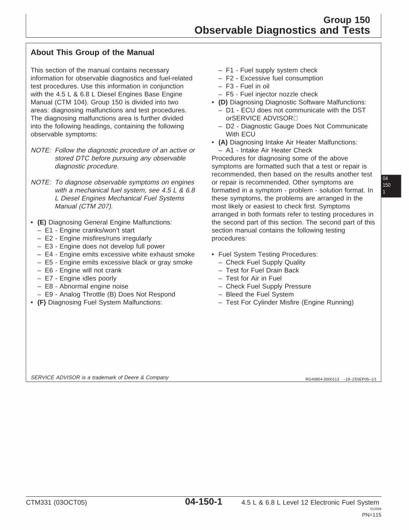
Group 150Observable Diagnostics and Tests
041501
RG40854,0000113 –19–23SEP05–1/1
About This Group of the Manual
This section of the manual contains necessaryinformation for observable diagnostics and fuel-relatedtest procedures. Use this information in conjunctionwith the 4.5 L & 6.8 L Diesel Engines Base EngineManual (CTM 104). Group 150 is divided into twoareas: diagnosing malfunctions and test procedures.The diagnosing malfunctions area is further dividedinto the following headings, containing the followingobservable symptoms:
NOTE: Follow the diagnostic procedure of an active orstored DTC before pursuing any observablediagnostic procedure.
NOTE: To diagnose observable symptoms on engineswith a mechanical fuel system, see 4.5 L & 6.8L Diesel Engines Mechanical Fuel SystemsManual (CTM 207).
• (E) Diagnosing General Engine Malfunctions:– E1 - Engine cranks/won’t start– E2 - Engine misfires/runs irregularly– E3 - Engine does not develop full power– E4 - Engine emits excessive white exhaust smoke– E5 - Engine emits excessive black or gray smoke– E6 - Engine will not crank– E7 - Engine idles poorly– E8 - Abnormal engine noise– E9 - Analog Throttle (B) Does Not Respond
• (F) Diagnosing Fuel System Malfunctions:
– F1 - Fuel supply system check– F2 - Excessive fuel consumption– F3 - Fuel in oil– F5 - Fuel injector nozzle check
• (D) Diagnosing Diagnostic Software Malfunctions:– D1 - ECU does not communicate with the DST
orSERVICE ADVISOR– D2 - Diagnostic Gauge Does Not Communicate
With ECU• (A) Diagnosing Intake Air Heater Malfunctions:
– A1 - Intake Air Heater CheckProcedures for diagnosing some of the abovesymptoms are formatted such that a test or repair isrecommended, then based on the results another testor repair is recommended. Other symptoms areformatted in a symptom - problem - solution format. Inthese symptoms, the problems are arranged in themost likely or easiest to check first. Symptomsarranged in both formats refer to testing procedures inthe second part of this section. The second part of thissection manual contains the following testingprocedures:
• Fuel System Testing Procedures:– Check Fuel Supply Quality– Test for Fuel Drain Back– Test for Air in Fuel– Check Fuel Supply Pressure– Bleed the Fuel System– Test For Cylinder Misfire (Engine Running)
SERVICE ADVISOR is a trademark of Deere & Company
CTM331 (03OCT05) 04-150-1 4.5 L & 6.8 L Level 12 Electronic Fuel System012506
PN=115
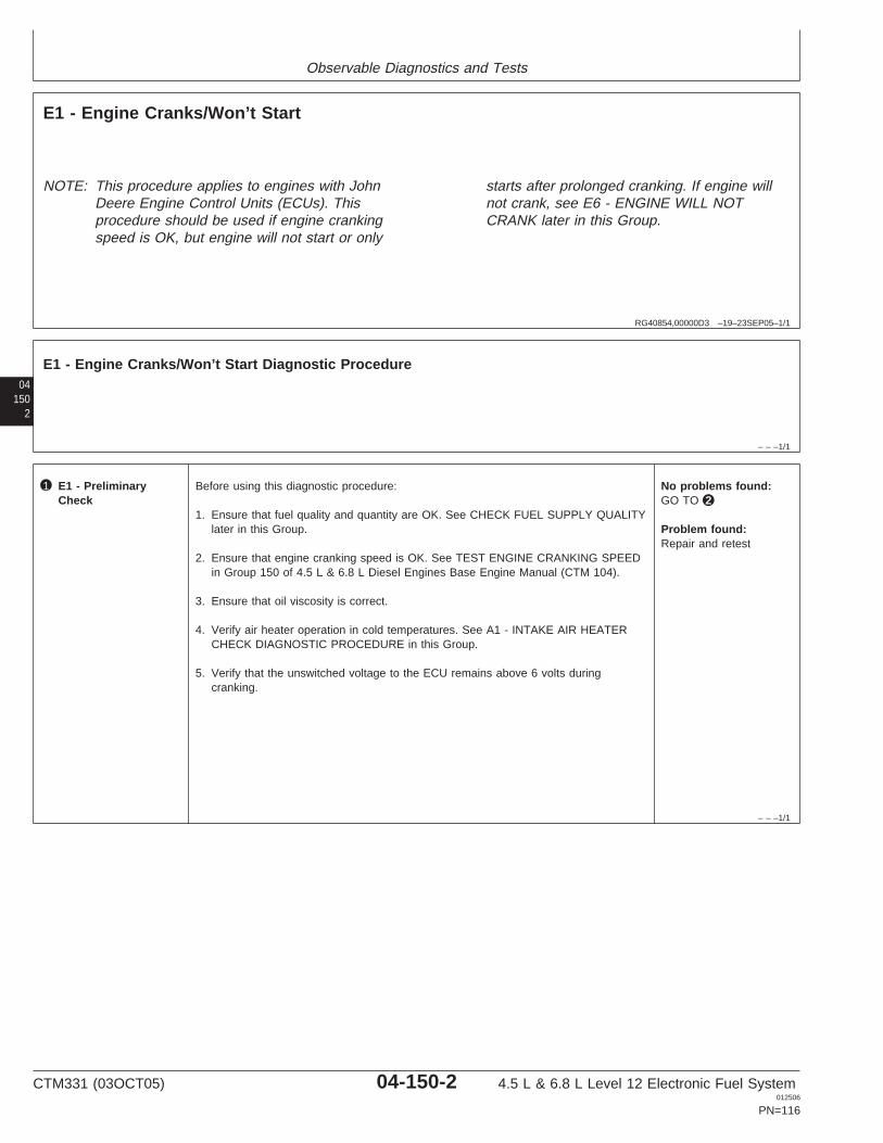
Observable Diagnostics and Tests
RG40854,00000D3 –19–23SEP05–1/1
E1 - Engine Cranks/Won’t Start
NOTE: This procedure applies to engines with JohnDeere Engine Control Units (ECUs). Thisprocedure should be used if engine crankingspeed is OK, but engine will not start or only
starts after prolonged cranking. If engine willnot crank, see E6 - ENGINE WILL NOTCRANK later in this Group.
04150
2
– – –1/1
E1 - Engine Cranks/Won’t Start Diagnostic Procedure
– – –1/1
1 E1 - PreliminaryCheck
Before using this diagnostic procedure:
1. Ensure that fuel quality and quantity are OK. See CHECK FUEL SUPPLY QUALITYlater in this Group.
2. Ensure that engine cranking speed is OK. See TEST ENGINE CRANKING SPEEDin Group 150 of 4.5 L & 6.8 L Diesel Engines Base Engine Manual (CTM 104).
3. Ensure that oil viscosity is correct.
4. Verify air heater operation in cold temperatures. See A1 - INTAKE AIR HEATERCHECK DIAGNOSTIC PROCEDURE in this Group.
5. Verify that the unswitched voltage to the ECU remains above 6 volts duringcranking.
No problems found:GO TO 2
Problem found:Repair and retest
CTM331 (03OCT05) 04-150-2 4.5 L & 6.8 L Level 12 Electronic Fuel System012506
PN=116
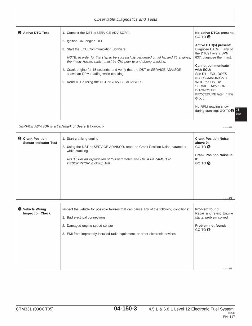
Observable Diagnostics and Tests
041503
– – –1/1
2 Active DTC Test 1. Connect the DST orSERVICE ADVISOR.
2. Ignition ON, engine OFF
3. Start the ECU Communication Software
NOTE: In order for this step to be successfully performed on all HL and TL engines,the 4-way Hazard switch must be ON, prior to and during cranking.
4. Crank engine for 15 seconds, and verify that the DST or SERVICE ADVISORshows an RPM reading while cranking.
5. Read DTCs using the DST orSERVICE ADVISOR.
No active DTCs present:GO TO 3
Active DTC(s) present:Diagnose DTCs. If any ofthe DTCs have a SPN637, diagnose them first.
Cannot communicatewith ECU:See D1 - ECU DOESNOT COMMUNICATEWITH the DST orSERVICE ADVISORDIAGNOSTICPROCEDURE later in thisGroup.
No RPM reading shownduring cranking: GO TO 4
SERVICE ADVISOR is a trademark of Deere & Company
– – –1/1
3 Crank PositionSensor Indicator Test
1. Start cranking engine
2. Using the DST or SERVICE ADVISOR, read the Crank Position Noise parameterwhile cranking.
NOTE: For an explanation of this parameter, see DATA PARAMETERDESCRIPTION in Group 160.
Crank Position Noiseabove 0:GO TO 4
Crank Position Noise is0:GO TO 5
– – –1/1
4 Vehicle WiringInspection Check
Inspect the vehicle for possible failures that can cause any of the following conditions:
1. Bad electrical connections
2. Damaged engine speed sensor
3. EMI from improperly installed radio equipment, or other electronic devices
Problem found:Repair and retest. Enginestarts, problem solved.
Problem not found:GO TO 5
CTM331 (03OCT05) 04-150-3 4.5 L & 6.8 L Level 12 Electronic Fuel System012506
PN=117
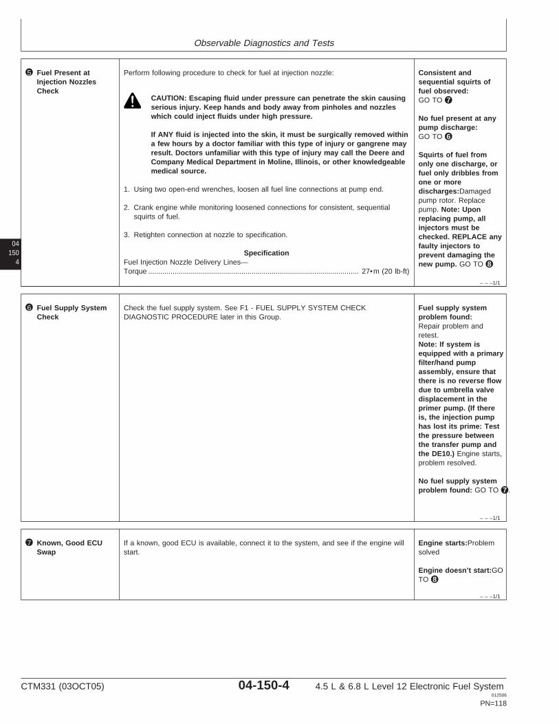
Observable Diagnostics and Tests
04150
4
– – –1/1
5 Fuel Present atInjection NozzlesCheck
Perform following procedure to check for fuel at injection nozzle:
CAUTION: Escaping fluid under pressure can penetrate the skin causingserious injury. Keep hands and body away from pinholes and nozzleswhich could inject fluids under high pressure.
If ANY fluid is injected into the skin, it must be surgically removed withina few hours by a doctor familiar with this type of injury or gangrene mayresult. Doctors unfamiliar with this type of injury may call the Deere andCompany Medical Department in Moline, Illinois, or other knowledgeablemedical source.
1. Using two open-end wrenches, loosen all fuel line connections at pump end.
2. Crank engine while monitoring loosened connections for consistent, sequentialsquirts of fuel.
3. Retighten connection at nozzle to specification.
SpecificationFuel Injection Nozzle Delivery Lines—Torque 27•m (20 lb-ft)........................................................................................................
Consistent andsequential squirts offuel observed:GO TO 7
No fuel present at anypump discharge:GO TO 6
Squirts of fuel fromonly one discharge, orfuel only dribbles fromone or moredischarges:Damagedpump rotor. Replacepump. Note: Uponreplacing pump, allinjectors must bechecked. REPLACE anyfaulty injectors toprevent damaging thenew pump. GO TO 8
– – –1/1
6 Fuel Supply SystemCheck
Check the fuel supply system. See F1 - FUEL SUPPLY SYSTEM CHECKDIAGNOSTIC PROCEDURE later in this Group.
Fuel supply systemproblem found:Repair problem andretest.Note: If system isequipped with a primaryfilter/hand pumpassembly, ensure thatthere is no reverse flowdue to umbrella valvedisplacement in theprimer pump. (If thereis, the injection pumphas lost its prime: Testthe pressure betweenthe transfer pump andthe DE10.) Engine starts,problem resolved.
No fuel supply systemproblem found: GO TO 7 .
– – –1/1
7 Known, Good ECUSwap
If a known, good ECU is available, connect it to the system, and see if the engine willstart.
Engine starts:Problemsolved
Engine doesn’t start:GOTO 8
CTM331 (03OCT05) 04-150-4 4.5 L & 6.8 L Level 12 Electronic Fuel System012506
PN=118
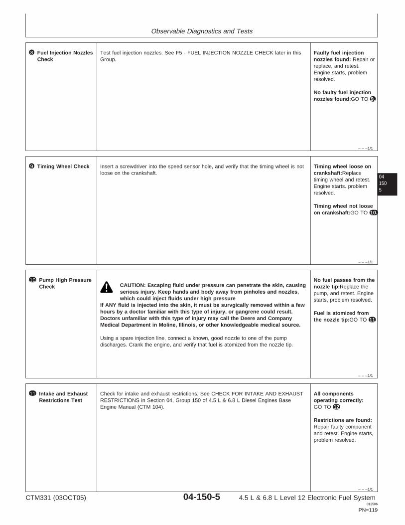
Observable Diagnostics and Tests
– – –1/1
8 Fuel Injection NozzlesCheck
Test fuel injection nozzles. See F5 - FUEL INJECTION NOZZLE CHECK later in thisGroup.
Faulty fuel injectionnozzles found: Repair orreplace, and retest.Engine starts, problemresolved.
No faulty fuel injectionnozzles found:GO TO 9.
041505
– – –1/1
9 Timing Wheel Check Insert a screwdriver into the speed sensor hole, and verify that the timing wheel is notloose on the crankshaft.
Timing wheel loose oncrankshaft:Replacetiming wheel and retest.Engine starts. problemresolved.
Timing wheel not looseon crankshaft:GO TO 10.
– – –1/1
10 Pump High PressureCheck CAUTION: Escaping fluid under pressure can penetrate the skin, causing
serious injury. Keep hands and body away from pinholes and nozzles,which could inject fluids under high pressure
If ANY fluid is injected into the skin, it must be survgically removed within a fewhours by a doctor familiar with this type of injury, or gangrene could result.Doctors unfamiliar with this type of injury may call the Deere and CompanyMedical Department in Moline, Illinois, or other knowledgeable medical source.
Using a spare injection line, connect a known, good nozzle to one of the pumpdischarges. Crank the engine, and verify that fuel is atomized from the nozzle tip.
No fuel passes from thenozzle tip:Replace thepump, and retest. Enginestarts, problem resolved.
Fuel is atomized fromthe nozzle tip:GO TO 11
– – –1/1
11 Intake and ExhaustRestrictions Test
Check for intake and exhaust restrictions. See CHECK FOR INTAKE AND EXHAUSTRESTRICTIONS in Section 04, Group 150 of 4.5 L & 6.8 L Diesel Engines BaseEngine Manual (CTM 104).
All componentsoperating correctly:GO TO 12
Restrictions are found:Repair faulty componentand retest. Engine starts,problem resolved.
CTM331 (03OCT05) 04-150-5 4.5 L & 6.8 L Level 12 Electronic Fuel System012506
PN=119
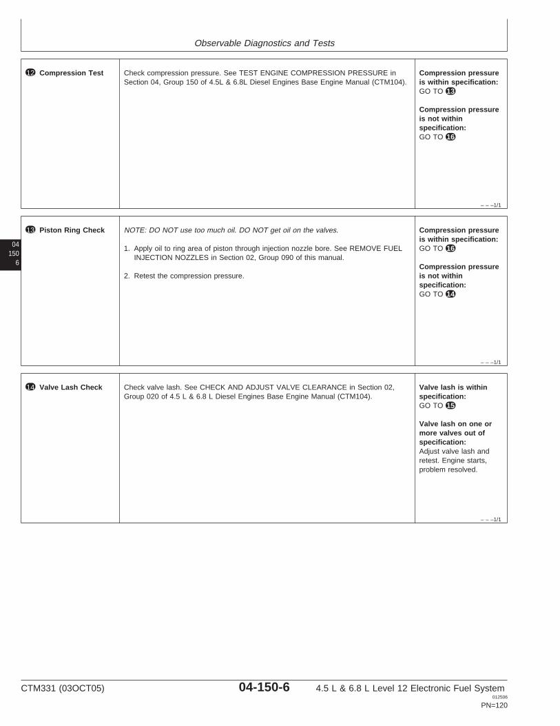
Observable Diagnostics and Tests
– – –1/1
12 Compression Test Check compression pressure. See TEST ENGINE COMPRESSION PRESSURE inSection 04, Group 150 of 4.5L & 6.8L Diesel Engines Base Engine Manual (CTM104).
Compression pressureis within specification:GO TO 13
Compression pressureis not withinspecification:GO TO 16
04150
6
– – –1/1
13 Piston Ring Check NOTE: DO NOT use too much oil. DO NOT get oil on the valves.
1. Apply oil to ring area of piston through injection nozzle bore. See REMOVE FUELINJECTION NOZZLES in Section 02, Group 090 of this manual.
2. Retest the compression pressure.
Compression pressureis within specification:GO TO 16
Compression pressureis not withinspecification:GO TO 14
– – –1/1
14 Valve Lash Check Check valve lash. See CHECK AND ADJUST VALVE CLEARANCE in Section 02,Group 020 of 4.5 L & 6.8 L Diesel Engines Base Engine Manual (CTM104).
Valve lash is withinspecification:GO TO 15
Valve lash on one ormore valves out ofspecification:Adjust valve lash andretest. Engine starts,problem resolved.
CTM331 (03OCT05) 04-150-6 4.5 L & 6.8 L Level 12 Electronic Fuel System012506
PN=120
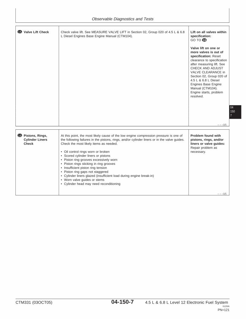
Observable Diagnostics and Tests
041507
– – –1/1
15 Valve Lift Check Check valve lift. See MEASURE VALVE LIFT in Section 02, Group 020 of 4.5 L & 6.8L Diesel Engines Base Engine Manual (CTM104).
Lift on all valves withinspecification:GO TO 16
Valve lift on one ormore valves is out ofspecification: Resetclearance to specificationafter measuring lift. SeeCHECK AND ADJUSTVALVE CLEARANCE inSection 02, Group 020 of4.5 L & 6.8 L DieselEngines Base EngineManual (CTM104).Engine starts, problemresolved.
– – –1/1
16 Pistons, Rings,Cylinder LinersCheck
At this point, the most likely cause of the low engine compression pressure is one ofthe following failures in the pistons, rings, and/or cylinder liners or in the valve guides.Check the most likely items as needed.
• Oil control rings worn or broken• Scored cylinder liners or pistons• Piston ring grooves excessively worn• Piston rings sticking in ring grooves• Insufficient piston ring tension• Piston ring gaps not staggered• Cylinder liners glazed (insufficient load during engine break-in)• Worn valve guides or stems• Cylinder head may need reconditioning
Problem found withpistons, rings, and/orliners or valve guides:Repair problem asnecessary.
CTM331 (03OCT05) 04-150-7 4.5 L & 6.8 L Level 12 Electronic Fuel System012506
PN=121
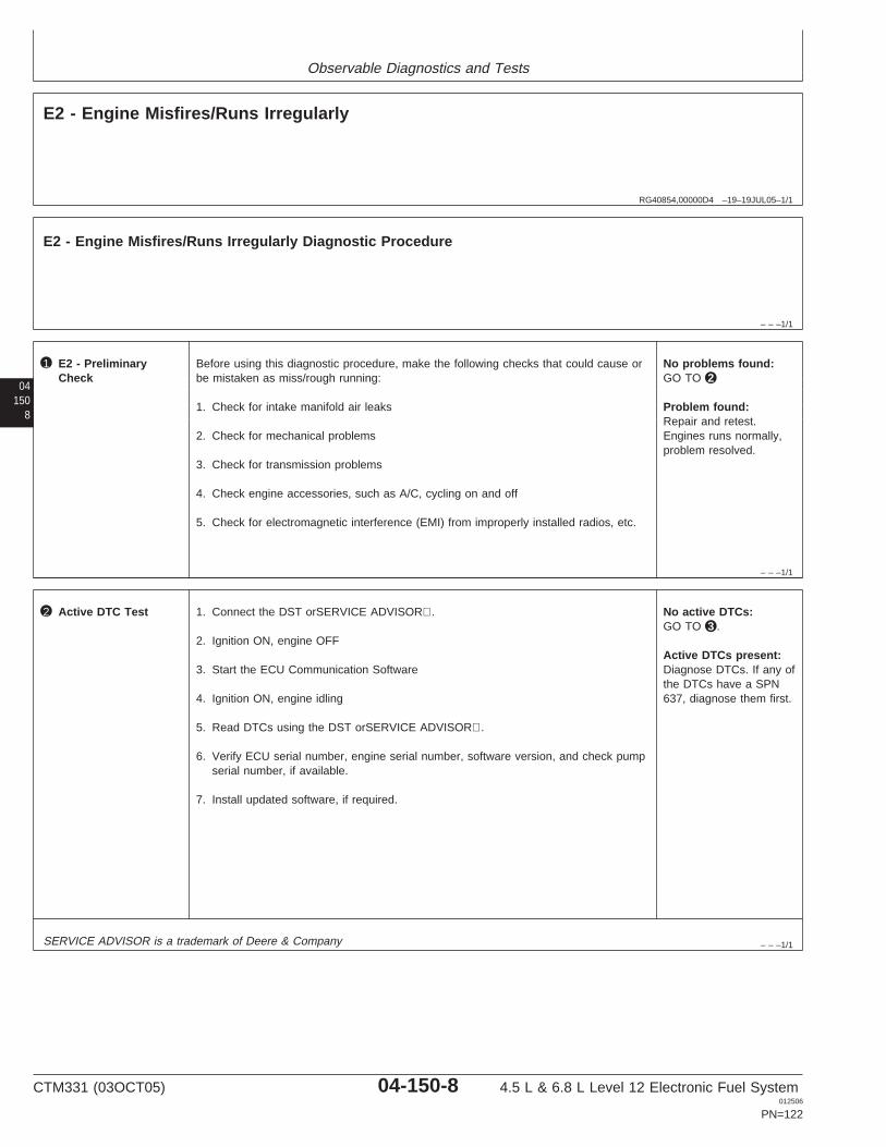
Observable Diagnostics and Tests
RG40854,00000D4 –19–19JUL05–1/1
E2 - Engine Misfires/Runs Irregularly
– – –1/1
E2 - Engine Misfires/Runs Irregularly Diagnostic Procedure
04150
8
– – –1/1
1 E2 - PreliminaryCheck
Before using this diagnostic procedure, make the following checks that could cause orbe mistaken as miss/rough running:
1. Check for intake manifold air leaks
2. Check for mechanical problems
3. Check for transmission problems
4. Check engine accessories, such as A/C, cycling on and off
5. Check for electromagnetic interference (EMI) from improperly installed radios, etc.
No problems found:GO TO 2
Problem found:Repair and retest.Engines runs normally,problem resolved.
– – –1/1
2 Active DTC Test 1. Connect the DST orSERVICE ADVISOR.
2. Ignition ON, engine OFF
3. Start the ECU Communication Software
4. Ignition ON, engine idling
5. Read DTCs using the DST orSERVICE ADVISOR.
6. Verify ECU serial number, engine serial number, software version, and check pumpserial number, if available.
7. Install updated software, if required.
No active DTCs:GO TO 3 .
Active DTCs present:Diagnose DTCs. If any ofthe DTCs have a SPN637, diagnose them first.
SERVICE ADVISOR is a trademark of Deere & Company
CTM331 (03OCT05) 04-150-8 4.5 L & 6.8 L Level 12 Electronic Fuel System012506
PN=122
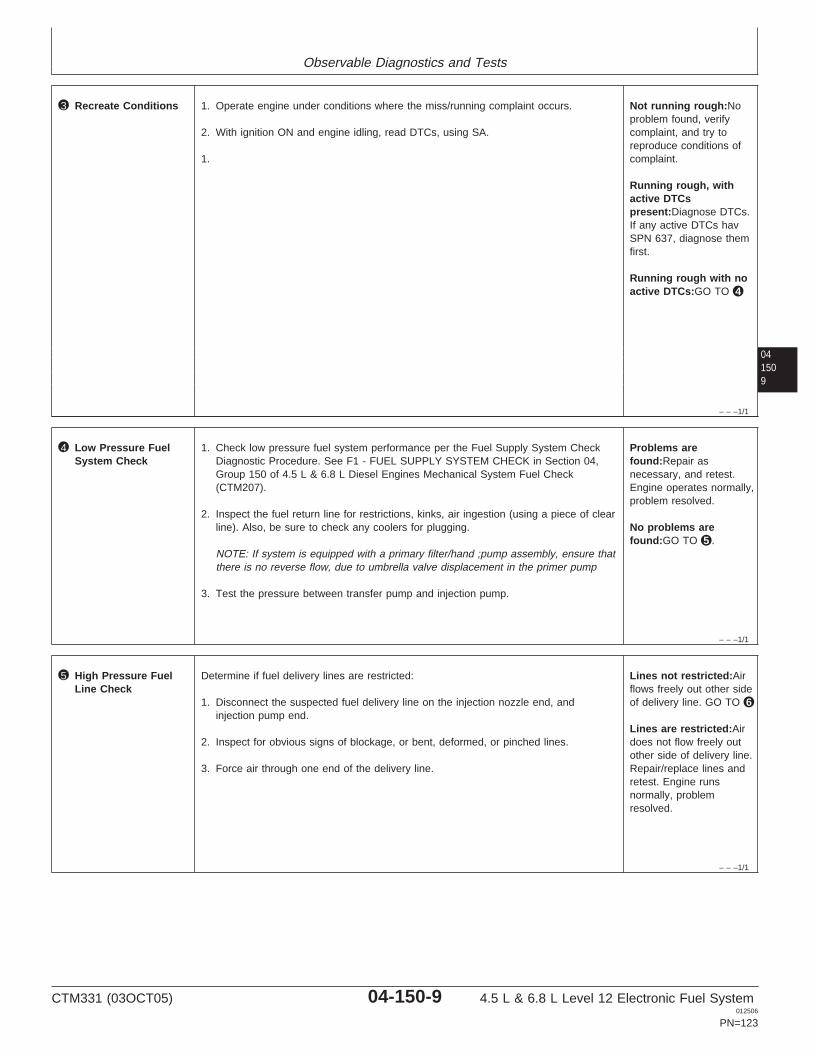
Observable Diagnostics and Tests
041509
– – –1/1
3 Recreate Conditions 1. Operate engine under conditions where the miss/running complaint occurs.
2. With ignition ON and engine idling, read DTCs, using SA.
1.
Not running rough:Noproblem found, verifycomplaint, and try toreproduce conditions ofcomplaint.
Running rough, withactive DTCspresent:Diagnose DTCs.If any active DTCs havSPN 637, diagnose themfirst.
Running rough with noactive DTCs:GO TO 4
– – –1/1
4 Low Pressure FuelSystem Check
1. Check low pressure fuel system performance per the Fuel Supply System CheckDiagnostic Procedure. See F1 - FUEL SUPPLY SYSTEM CHECK in Section 04,Group 150 of 4.5 L & 6.8 L Diesel Engines Mechanical System Fuel Check(CTM207).
2. Inspect the fuel return line for restrictions, kinks, air ingestion (using a piece of clearline). Also, be sure to check any coolers for plugging.
NOTE: If system is equipped with a primary filter/hand ;pump assembly, ensure thatthere is no reverse flow, due to umbrella valve displacement in the primer pump
3. Test the pressure between transfer pump and injection pump.
Problems arefound:Repair asnecessary, and retest.Engine operates normally,problem resolved.
No problems arefound:GO TO 5 .
– – –1/1
5 High Pressure FuelLine Check
Determine if fuel delivery lines are restricted:
1. Disconnect the suspected fuel delivery line on the injection nozzle end, andinjection pump end.
2. Inspect for obvious signs of blockage, or bent, deformed, or pinched lines.
3. Force air through one end of the delivery line.
Lines not restricted:Airflows freely out other sideof delivery line. GO TO 6
Lines are restricted:Airdoes not flow freely outother side of delivery line.Repair/replace lines andretest. Engine runsnormally, problemresolved.
CTM331 (03OCT05) 04-150-9 4.5 L & 6.8 L Level 12 Electronic Fuel System012506
PN=123
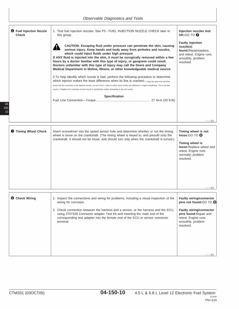
Observable Diagnostics and Tests
04150
10
– – –1/1
6 Fuel Injection NozzleCheck
1. Test fuel injection nozzles. See F5 - FUEL INJECTION NOZZLE CHECK later inthis group.
CAUTION: Escaping fluid under pressure can penetrate the skin, causingserious injury. Keep hands and body away from pinholes and nozzles,which could inject fluids under high pressure
If ANY fluid is injected into the skin, it must be survgically removed within a fewhours by a doctor familiar with this type of injury, or gangrene could result.Doctors unfamiliar with this type of injury may call the Deere and CompanyMedical Department in Moline, Illinois, or other knowledgeable medical source.
2.To help identify which nozzle is bad, perform the following procedure to determinewhich injector makes the least difference when its line is cracked:1. Using two open-end wrenches,
loosen fuel line connection at the injection nozzles, one at a time.2. Listen to which nozzle makes less difference in engine smoothness. This is the bad
nozzle.3. Retighten the connection at each nozzle to specification, before proceeding to the next nozzle.
SpecificationFuel Line Connection—Torque 27 N•m (20 ft-lb)..............................................................
Injection nozzles testOK:GO TO 7
Faulty injectionnozzle(s)found.Repair/replace,and retest. Engine runssmoothly, problemresolved.
– – –1/1
7 Timing Wheel Check Insert screwdriver into the speed sensor hole and determine whether or not the timingwheel is loose on the crankshaft. (The timing wheel is keyed to, and pressfit onto thecrankshaft. It should not be loose, and should turn only when the crankshaft is turned.)
Timing wheel is notloose:GO TO 8
Timing wheel isloose:Replace wheel andretest. Engine runsnormally, problemresolved.
– – –1/1
8 Check Wiring 1. Inspect the connections and wiring for problems, including a visual inspection of thewiring for corrosion.
2. Check connection between the harness and a sensor, or the harness and the ECU,using JT07328 Connector adapter Test Kit and inserting the male end of thecorresponding test adapter into the female end of the ECU or sensor connectorterminal.
Faulty wiring/connectorpins not found:GO TO 9 .
Faulty wiring/connectorpins found:Repair andretest. Engine runssmoothly, problemresolved.
CTM331 (03OCT05) 04-150-10 4.5 L & 6.8 L Level 12 Electronic Fuel System012506
PN=124
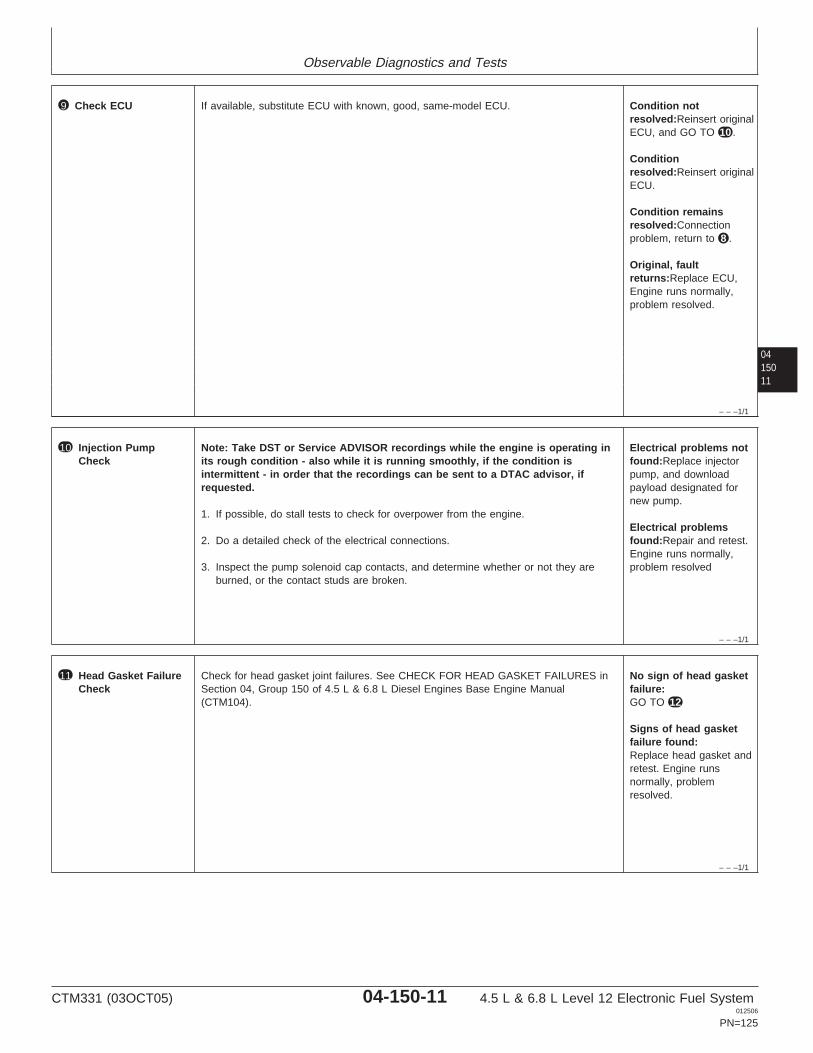
Observable Diagnostics and Tests
0415011
– – –1/1
9 Check ECU If available, substitute ECU with known, good, same-model ECU. Condition notresolved:Reinsert originalECU, and GO TO 10 .
Conditionresolved:Reinsert originalECU.
Condition remainsresolved:Connectionproblem, return to 8 .
Original, faultreturns:Replace ECU,Engine runs normally,problem resolved.
– – –1/1
10 Injection PumpCheck
Note: Take DST or Service ADVISOR recordings while the engine is operating inits rough condition - also while it is running smoothly, if the condition isintermittent - in order that the recordings can be sent to a DTAC advisor, ifrequested.
1. If possible, do stall tests to check for overpower from the engine.
2. Do a detailed check of the electrical connections.
3. Inspect the pump solenoid cap contacts, and determine whether or not they areburned, or the contact studs are broken.
Electrical problems notfound:Replace injectorpump, and downloadpayload designated fornew pump.
Electrical problemsfound:Repair and retest.Engine runs normally,problem resolved
– – –1/1
11 Head Gasket FailureCheck
Check for head gasket joint failures. See CHECK FOR HEAD GASKET FAILURES inSection 04, Group 150 of 4.5 L & 6.8 L Diesel Engines Base Engine Manual(CTM104).
No sign of head gasketfailure:GO TO 12
Signs of head gasketfailure found:Replace head gasket andretest. Engine runsnormally, problemresolved.
CTM331 (03OCT05) 04-150-11 4.5 L & 6.8 L Level 12 Electronic Fuel System012506
PN=125
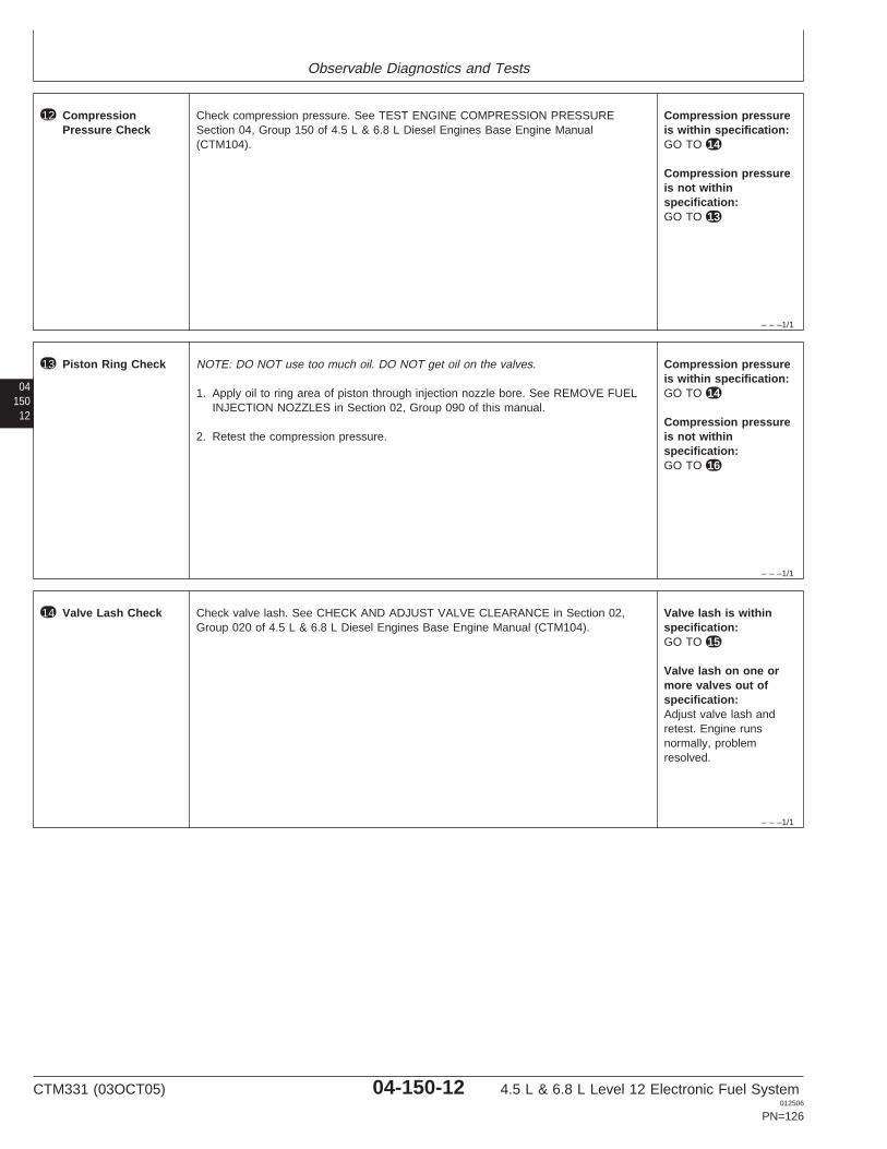
Observable Diagnostics and Tests
– – –1/1
12 CompressionPressure Check
Check compression pressure. See TEST ENGINE COMPRESSION PRESSURESection 04, Group 150 of 4.5 L & 6.8 L Diesel Engines Base Engine Manual(CTM104).
Compression pressureis within specification:GO TO 14
Compression pressureis not withinspecification:GO TO 13
04150
12
– – –1/1
13 Piston Ring Check NOTE: DO NOT use too much oil. DO NOT get oil on the valves.
1. Apply oil to ring area of piston through injection nozzle bore. See REMOVE FUELINJECTION NOZZLES in Section 02, Group 090 of this manual.
2. Retest the compression pressure.
Compression pressureis within specification:GO TO 14
Compression pressureis not withinspecification:GO TO 16
– – –1/1
14 Valve Lash Check Check valve lash. See CHECK AND ADJUST VALVE CLEARANCE in Section 02,Group 020 of 4.5 L & 6.8 L Diesel Engines Base Engine Manual (CTM104).
Valve lash is withinspecification:GO TO 15
Valve lash on one ormore valves out ofspecification:Adjust valve lash andretest. Engine runsnormally, problemresolved.
CTM331 (03OCT05) 04-150-12 4.5 L & 6.8 L Level 12 Electronic Fuel System012506
PN=126

Observable Diagnostics and Tests
0415013
– – –1/1
15 Valve Lift Check Check valve lift. See MEASURE VALVE LIFT in Group 020 in Section 02 of 4.5L &6.8L Diesel Engines Base Engine Manual (CTM104).
Lift on all valves withinspecification:GO TO 16
Valve lift on one ormore valves is out ofspecification: Resetclearance to specificationafter measuring lift. SeeCHECK AND ADJUSTVALVE CLEARANCE inSection 02, Group 020 of4.5 L & 6.8 L DieselEngines Base EngineManual (CTM104).Retest. Engine runsnormally, problemresolved.
– – –1/1
16 Pistons, Rings,Cylinder LinersCheck
At this point, the most likely cause of the low engine compression pressure is one ofthe following failures in the pistons, rings, and/or cylinder liners or in the valve guides.Check the most likely items as needed.
• Oil control rings worn or broken• Scored cylinder liners or pistons• Piston ring grooves excessively worn• Piston rings sticking in ring grooves• Insufficient piston ring tension• Piston ring gaps not staggered• Cylinder liners glazed (insufficient load during engine break-in)• Worn valve guides or stems• Cylinder head may need reconditioning
Problem found withpistons, rings, and/orliners or valve guides:Repair problem asnecessary, and retest.
CTM331 (03OCT05) 04-150-13 4.5 L & 6.8 L Level 12 Electronic Fuel System012506
PN=127
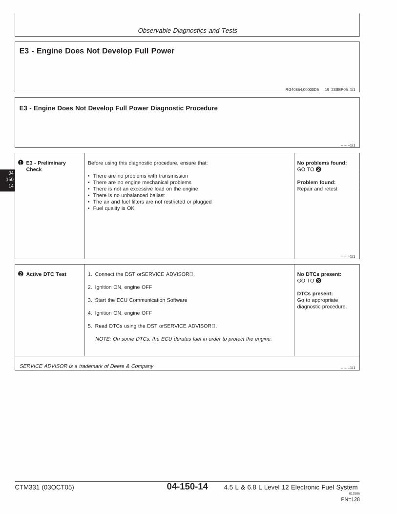
Observable Diagnostics and Tests
RG40854,00000D5 –19–23SEP05–1/1
E3 - Engine Does Not Develop Full Power
– – –1/1
E3 - Engine Does Not Develop Full Power Diagnostic Procedure
04150
14
– – –1/1
1 E3 - PreliminaryCheck
Before using this diagnostic procedure, ensure that:
• There are no problems with transmission• There are no engine mechanical problems• There is not an excessive load on the engine• There is no unbalanced ballast• The air and fuel filters are not restricted or plugged• Fuel quality is OK
No problems found:GO TO 2
Problem found:Repair and retest
– – –1/1
2 Active DTC Test 1. Connect the DST orSERVICE ADVISOR.
2. Ignition ON, engine OFF
3. Start the ECU Communication Software
4. Ignition ON, engine OFF
5. Read DTCs using the DST orSERVICE ADVISOR.
NOTE: On some DTCs, the ECU derates fuel in order to protect the engine.
No DTCs present:GO TO 3
DTCs present:Go to appropriatediagnostic procedure.
SERVICE ADVISOR is a trademark of Deere & Company
CTM331 (03OCT05) 04-150-14 4.5 L & 6.8 L Level 12 Electronic Fuel System012506
PN=128
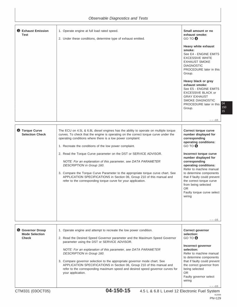
Observable Diagnostics and Tests
0415015
– – –1/1
3 Exhaust EmissionTest
1. Operate engine at full load rated speed.
2. Under these conditions, determine type of exhaust emitted.
Small amount or noexhaust smoke:GO TO 4
Heavy white exhaustsmoke:See E4 - ENGINE EMITSEXCESSIVE WHITEEXHAUST SMOKEDIAGNOSTICPROCEDURE later in thisGroup.
Heavy black or grayexhaust smoke:See E5 - ENGINE EMITSEXCESSIVE BLACK orGRAY EXHAUSTSMOKE DIAGNOSTICPROCEDURE later in thisGroup.
– – –1/1
4 Torque CurveSelection Check
The ECU on 4.5L & 6.8L diesel engines has the ability to operate on multiple torquecurves. To check that the engine is operating on the correct torque curve under theoperating conditions where there is a low power complaint:
1. Recreate the conditions of the low power complaint.
2. Read the Torque Curve parameter on the DST or SERVICE ADVISOR.
NOTE: For an explanation of this parameter, see DATA PARAMETERDESCRIPTION in Group 160.
3. Compare the Torque Curve Parameter to the appropriate torque curve chart. SeeAPPLICATION SPECIFICATIONS in Section 06, Group 210 of this manual andrefer to the corresponding torque curve for your application.
Correct torque curvenumber displayed forcorrespondingoperating conditions:GO TO 5
Incorrect torque curvenumber displayed forcorrespondingoperating conditions:Refer to machine manualto determine componentsthat if faulty could preventthe correct torque curvefrom being selectedORFaulty torque curve selectwiring
– – –1/1
5 Governor DroopMode SelectionCheck
1. Operate engine and attempt to recreate the low power condition.
2. Read the Desired Speed Governor parameter and the Maximum Speed Governorparameter using the DST or SERVICE ADVISOR.
NOTE: For an explanation of this parameter, see DATA PARAMETERDESCRIPTION in Group 160.
3. Compare governor selection to the appropriate governor mode chart. SeeAPPLICATION SPECIFICATIONS in Section 06, Group 210 of this manual andrefer to the corresponding maximum speed and desired speed governor curves foryour application.
Correct governorselection:GO TO 6
Incorrect governorselection:Refer to machine manualto determine componentsthat if faulty could preventthe correct governor frombeing selectedORFaulty governor selectwiring
CTM331 (03OCT05) 04-150-15 4.5 L & 6.8 L Level 12 Electronic Fuel System012506
PN=129
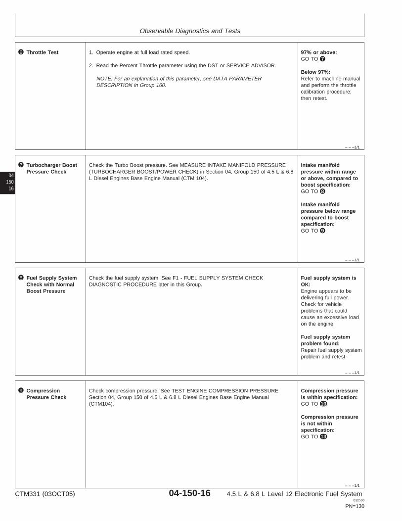
Observable Diagnostics and Tests
– – –1/1
6 Throttle Test 1. Operate engine at full load rated speed.
2. Read the Percent Throttle parameter using the DST or SERVICE ADVISOR.
NOTE: For an explanation of this parameter, see DATA PARAMETERDESCRIPTION in Group 160.
97% or above:GO TO 7
Below 97%:Refer to machine manualand perform the throttlecalibration procedure;then retest.
04150
16
– – –1/1
7 Turbocharger BoostPressure Check
Check the Turbo Boost pressure. See MEASURE INTAKE MANIFOLD PRESSURE(TURBOCHARGER BOOST/POWER CHECK) in Section 04, Group 150 of 4.5 L & 6.8L Diesel Engines Base Engine Manual (CTM 104).
Intake manifoldpressure within rangeor above, compared toboost specification:GO TO 8
Intake manifoldpressure below rangecompared to boostspecification:GO TO 9
– – –1/1
8 Fuel Supply SystemCheck with NormalBoost Pressure
Check the fuel supply system. See F1 - FUEL SUPPLY SYSTEM CHECKDIAGNOSTIC PROCEDURE later in this Group.
Fuel supply system isOK:Engine appears to bedelivering full power.Check for vehicleproblems that couldcause an excessive loadon the engine.
Fuel supply systemproblem found:Repair fuel supply systemproblem and retest.
– – –1/1
9 CompressionPressure Check
Check compression pressure. See TEST ENGINE COMPRESSION PRESSURESection 04, Group 150 of 4.5 L & 6.8 L Diesel Engines Base Engine Manual(CTM104).
Compression pressureis within specification:GO TO 10
Compression pressureis not withinspecification:GO TO 13
CTM331 (03OCT05) 04-150-16 4.5 L & 6.8 L Level 12 Electronic Fuel System012506
PN=130
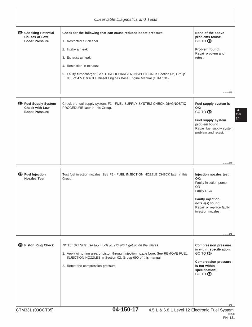
Observable Diagnostics and Tests
– – –1/1
10 Checking PotentialCauses of LowBoost Pressure
Check for the following that can cause reduced boost pressure:
1. Restricted air cleaner
2. Intake air leak
3. Exhaust air leak
4. Restriction in exhaust
5. Faulty turbocharger. See TURBOCHARGER INSPECTION in Section 02, Group080 of 4.5 L & 6.8 L Diesel Engines Base Engine Manual (CTM 104).
None of the aboveproblems found:GO TO 11
Problem found:Repair problem andretest.
0415017
– – –1/1
11 Fuel Supply SystemCheck with LowBoost Pressure
Check the fuel supply system. F1 - FUEL SUPPLY SYSTEM CHECK DIAGNOSTICPROCEDURE later in this Group.
Fuel supply system isOK:GO TO 12
Fuel supply systemproblem found:Repair fuel supply systemproblem and retest.
– – –1/1
12 Fuel InjectionNozzles Test
Test fuel injection nozzles. See F5 - FUEL INJECTION NOZZLE CHECK later in thisGroup.
Injection nozzles testOK:Faulty injection pumpORFaulty ECU
Faulty injectionnozzle(s) found:Repair or replace faultyinjection nozzles.
– – –1/1
13 Piston Ring Check NOTE: DO NOT use too much oil. DO NOT get oil on the valves.
1. Apply oil to ring area of piston through injection nozzle bore. See REMOVE FUELINJECTION NOZZLES in Section 02, Group 090 of this manual.
2. Retest the compression pressure.
Compression pressureis within specification:GO TO 16
Compression pressureis not withinspecification:GO TO 14
CTM331 (03OCT05) 04-150-17 4.5 L & 6.8 L Level 12 Electronic Fuel System012506
PN=131
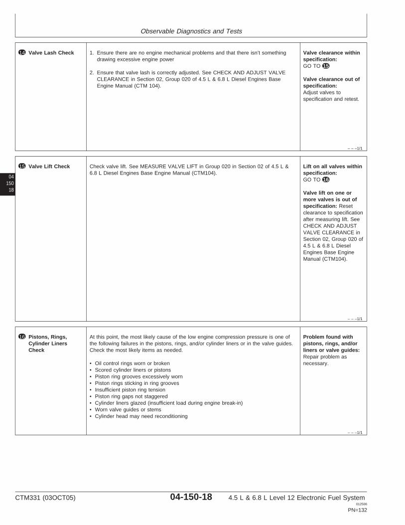
Observable Diagnostics and Tests
– – –1/1
14 Valve Lash Check 1. Ensure there are no engine mechanical problems and that there isn’t somethingdrawing excessive engine power
2. Ensure that valve lash is correctly adjusted. See CHECK AND ADJUST VALVECLEARANCE in Section 02, Group 020 of 4.5 L & 6.8 L Diesel Engines BaseEngine Manual (CTM 104).
Valve clearance withinspecification:GO TO 15
Valve clearance out ofspecification:Adjust valves tospecification and retest.
04150
18
– – –1/1
15 Valve Lift Check Check valve lift. See MEASURE VALVE LIFT in Group 020 in Section 02 of 4.5 L &6.8 L Diesel Engines Base Engine Manual (CTM104).
Lift on all valves withinspecification:GO TO 16
Valve lift on one ormore valves is out ofspecification: Resetclearance to specificationafter measuring lift. SeeCHECK AND ADJUSTVALVE CLEARANCE inSection 02, Group 020 of4.5 L & 6.8 L DieselEngines Base EngineManual (CTM104).
– – –1/1
16 Pistons, Rings,Cylinder LinersCheck
At this point, the most likely cause of the low engine compression pressure is one ofthe following failures in the pistons, rings, and/or cylinder liners or in the valve guides.Check the most likely items as needed.
• Oil control rings worn or broken• Scored cylinder liners or pistons• Piston ring grooves excessively worn• Piston rings sticking in ring grooves• Insufficient piston ring tension• Piston ring gaps not staggered• Cylinder liners glazed (insufficient load during engine break-in)• Worn valve guides or stems• Cylinder head may need reconditioning
Problem found withpistons, rings, and/orliners or valve guides:Repair problem asnecessary.
CTM331 (03OCT05) 04-150-18 4.5 L & 6.8 L Level 12 Electronic Fuel System012506
PN=132
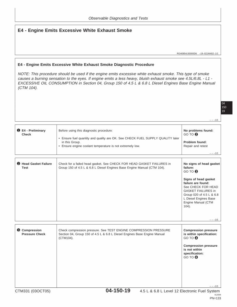
Observable Diagnostics and Tests
RG40854,00000D6 –19–02JAN02–1/1
E4 - Engine Emits Excessive White Exhaust Smoke
0415019
– – –1/1
E4 - Engine Emits Excessive White Exhaust Smoke Diagnostic Procedure
NOTE: This procedure should be used if the engine emits excessive white exhaust smoke. This type of smokecauses a burning sensation to the eyes. If engine emits a less heavy, bluish exhaust smoke see 4.5L/6.8L - L1 -EXCESSIVE OIL CONSUMPTION in Section 04, Group 150 of 4.5 L & 6.8 L Diesel Engines Base Engine Manual(CTM 104).
– – –1/1
1 E4 - PreliminaryCheck
Before using this diagnostic procedure:
• Ensure fuel quantity and quality are OK. See CHECK FUEL SUPPLY QUALITY laterin this Group.
• Ensure engine coolant temperature is not extremely low.
No problems found:GO TO 2
Problem found:Repair and retest
– – –1/1
2 Head Gasket FailureTest
Check for a failed head gasket. See CHECK FOR HEAD GASKET FAILURES inGroup 150 of 4.5 L & 6.8 L Diesel Engines Base Engine Manual (CTM 104).
No signs of head gasketfailure:GO TO 3
Signs of head gasketfailure are found:See CHECK FOR HEADGASKET FAILURES inGroup 020 of 4.5 L & 6.8L Diesel Engines BaseEngine Manual (CTM104).
– – –1/1
3 CompressionPressure Check
Check compression pressure. See TEST ENGINE COMPRESSION PRESSURESection 04, Group 150 of 4.5 L & 6.8 L Diesel Engines Base Engine Manual(CTM104).
Compression pressureis within specification:GO TO 4
Compression pressureis not withinspecification:GO TO 6
CTM331 (03OCT05) 04-150-19 4.5 L & 6.8 L Level 12 Electronic Fuel System012506
PN=133
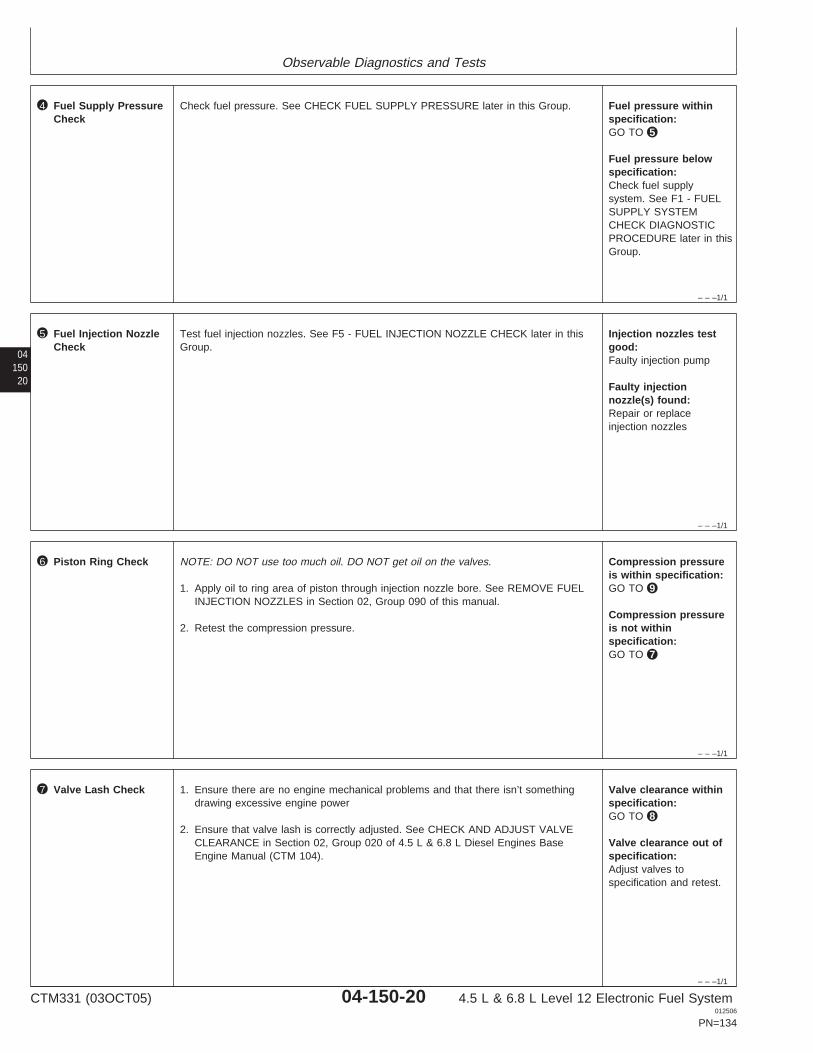
Observable Diagnostics and Tests
– – –1/1
4 Fuel Supply PressureCheck
Check fuel pressure. See CHECK FUEL SUPPLY PRESSURE later in this Group. Fuel pressure withinspecification:GO TO 5
Fuel pressure belowspecification:Check fuel supplysystem. See F1 - FUELSUPPLY SYSTEMCHECK DIAGNOSTICPROCEDURE later in thisGroup.
04150
20
– – –1/1
5 Fuel Injection NozzleCheck
Test fuel injection nozzles. See F5 - FUEL INJECTION NOZZLE CHECK later in thisGroup.
Injection nozzles testgood:Faulty injection pump
Faulty injectionnozzle(s) found:Repair or replaceinjection nozzles
– – –1/1
6 Piston Ring Check NOTE: DO NOT use too much oil. DO NOT get oil on the valves.
1. Apply oil to ring area of piston through injection nozzle bore. See REMOVE FUELINJECTION NOZZLES in Section 02, Group 090 of this manual.
2. Retest the compression pressure.
Compression pressureis within specification:GO TO 9
Compression pressureis not withinspecification:GO TO 7
– – –1/1
7 Valve Lash Check 1. Ensure there are no engine mechanical problems and that there isn’t somethingdrawing excessive engine power
2. Ensure that valve lash is correctly adjusted. See CHECK AND ADJUST VALVECLEARANCE in Section 02, Group 020 of 4.5 L & 6.8 L Diesel Engines BaseEngine Manual (CTM 104).
Valve clearance withinspecification:GO TO 8
Valve clearance out ofspecification:Adjust valves tospecification and retest.
CTM331 (03OCT05) 04-150-20 4.5 L & 6.8 L Level 12 Electronic Fuel System012506
PN=134

Observable Diagnostics and Tests
0415021
– – –1/1
8 Valve Lift Check Check valve lift. See MEASURE VALVE LIFT in Group 020 in Section 02 of 4.5 L &6.8 L Diesel Engines Base Engine Manual (CTM104).
Lift on all valves withinspecification:GO TO 9
Valve lift on one ormore valves is out ofspecification: Resetclearance to specificationafter measuring lift. SeeCHECK AND ADJUSTVALVE CLEARANCE inSection 02, Group 020 of4.5 L & 6.8 L DieselEngines Base EngineManual (CTM104).
– – –1/1
9 Pistons, Rings,Cylinder Liners Check
At this point, the most likely cause of the low engine compression pressure is one ofthe following failures in the pistons, rings, and/or cylinder liners or in the valve guides.Check the most likely items as needed.
• Oil control rings worn or broken• Scored cylinder liners or pistons• Piston ring grooves excessively worn• Piston rings sticking in ring grooves• Insufficient piston ring tension• Piston ring gaps not staggered• Cylinder liners glazed (insufficient load during engine break-in)• Worn valve guides or stems• Cylinder head may need reconditioning
Problem found withpistons, rings, and/orliners or valve guides:Repair problem asnecessary.
CTM331 (03OCT05) 04-150-21 4.5 L & 6.8 L Level 12 Electronic Fuel System012506
PN=135
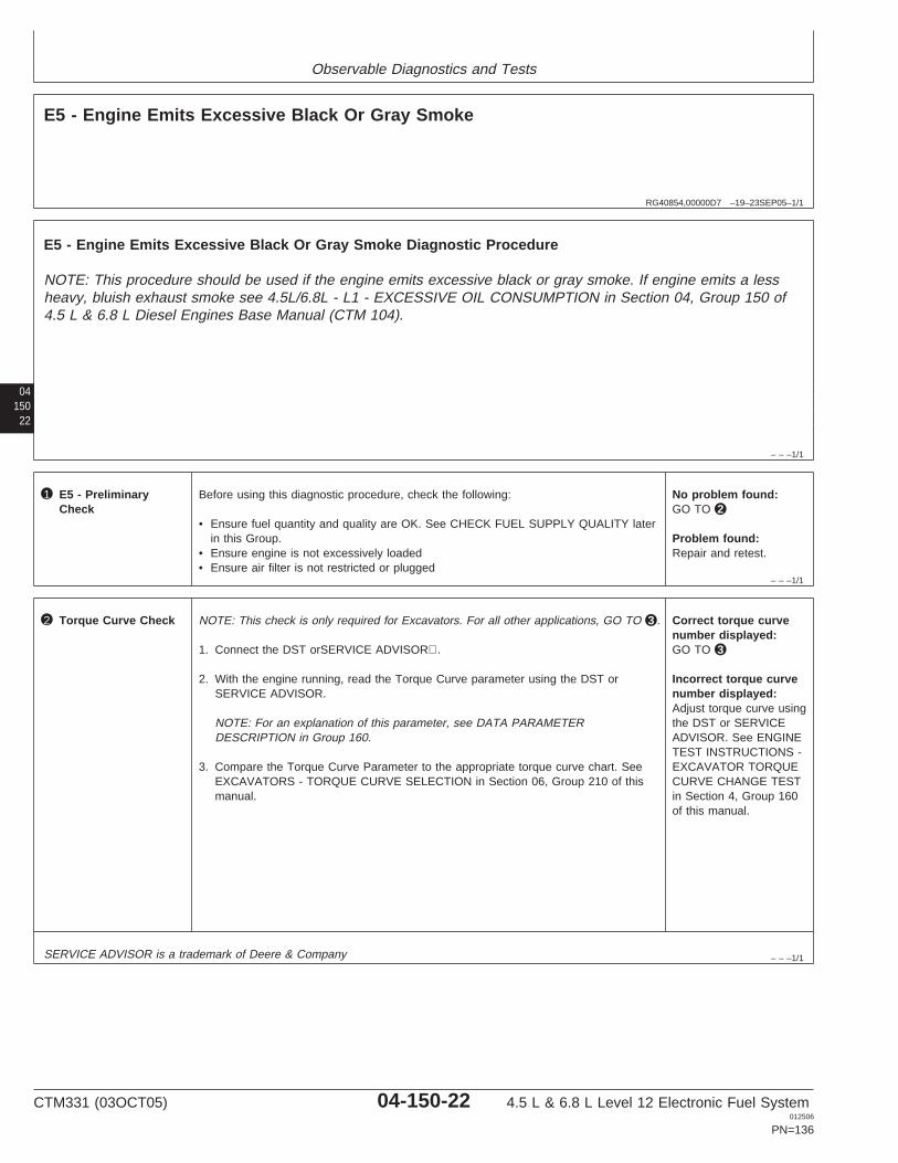
Observable Diagnostics and Tests
RG40854,00000D7 –19–23SEP05–1/1
E5 - Engine Emits Excessive Black Or Gray Smoke
04150
22
– – –1/1
E5 - Engine Emits Excessive Black Or Gray Smoke Diagnostic Procedure
NOTE: This procedure should be used if the engine emits excessive black or gray smoke. If engine emits a lessheavy, bluish exhaust smoke see 4.5L/6.8L - L1 - EXCESSIVE OIL CONSUMPTION in Section 04, Group 150 of4.5 L & 6.8 L Diesel Engines Base Manual (CTM 104).
– – –1/1
1 E5 - PreliminaryCheck
Before using this diagnostic procedure, check the following:
• Ensure fuel quantity and quality are OK. See CHECK FUEL SUPPLY QUALITY laterin this Group.
• Ensure engine is not excessively loaded• Ensure air filter is not restricted or plugged
No problem found:GO TO 2
Problem found:Repair and retest.
– – –1/1
2 Torque Curve Check NOTE: This check is only required for Excavators. For all other applications, GO TO 3 .
1. Connect the DST orSERVICE ADVISOR.
2. With the engine running, read the Torque Curve parameter using the DST orSERVICE ADVISOR.
NOTE: For an explanation of this parameter, see DATA PARAMETERDESCRIPTION in Group 160.
3. Compare the Torque Curve Parameter to the appropriate torque curve chart. SeeEXCAVATORS - TORQUE CURVE SELECTION in Section 06, Group 210 of thismanual.
Correct torque curvenumber displayed:GO TO 3
Incorrect torque curvenumber displayed:Adjust torque curve usingthe DST or SERVICEADVISOR. See ENGINETEST INSTRUCTIONS -EXCAVATOR TORQUECURVE CHANGE TESTin Section 4, Group 160of this manual.
SERVICE ADVISOR is a trademark of Deere & Company
CTM331 (03OCT05) 04-150-22 4.5 L & 6.8 L Level 12 Electronic Fuel System012506
PN=136
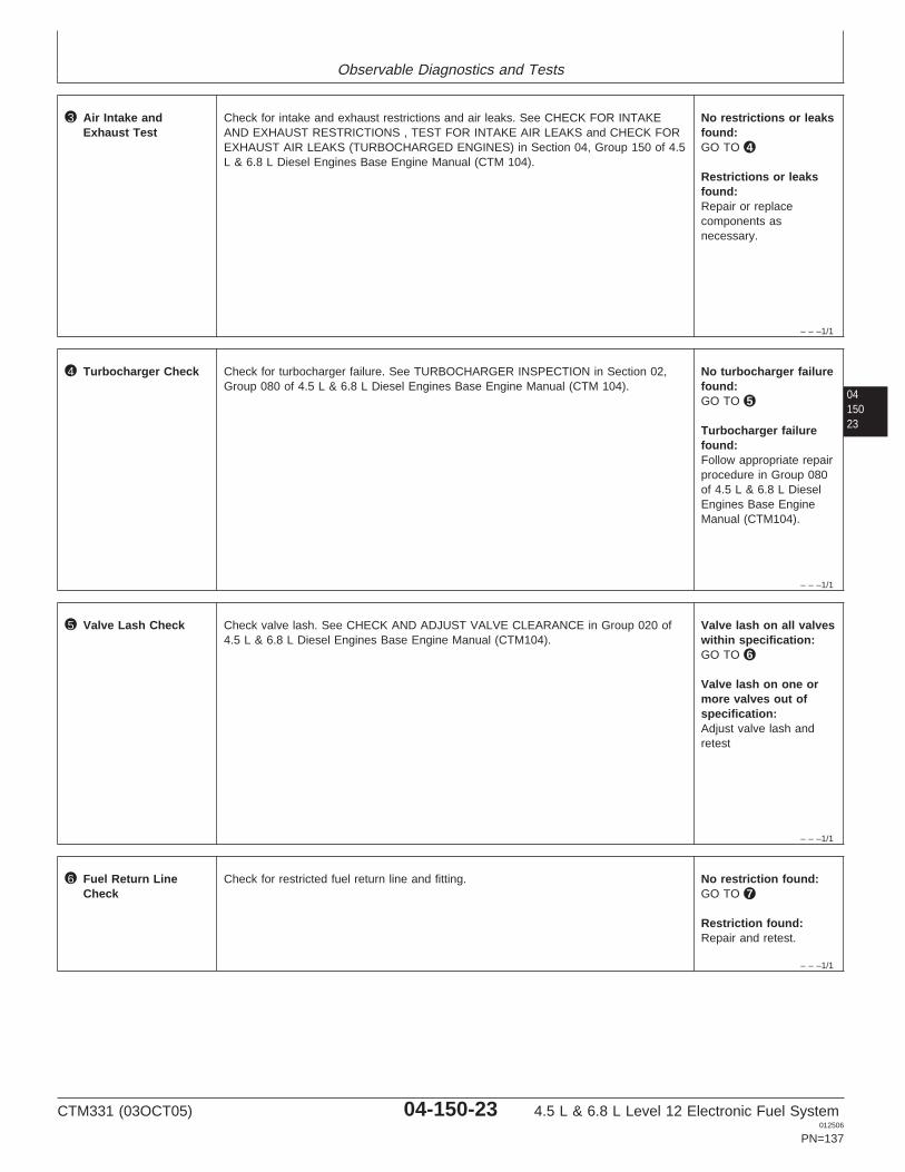
Observable Diagnostics and Tests
– – –1/1
3 Air Intake andExhaust Test
Check for intake and exhaust restrictions and air leaks. See CHECK FOR INTAKEAND EXHAUST RESTRICTIONS , TEST FOR INTAKE AIR LEAKS and CHECK FOREXHAUST AIR LEAKS (TURBOCHARGED ENGINES) in Section 04, Group 150 of 4.5L & 6.8 L Diesel Engines Base Engine Manual (CTM 104).
No restrictions or leaksfound:GO TO 4
Restrictions or leaksfound:Repair or replacecomponents asnecessary.
0415023
– – –1/1
4 Turbocharger Check Check for turbocharger failure. See TURBOCHARGER INSPECTION in Section 02,Group 080 of 4.5 L & 6.8 L Diesel Engines Base Engine Manual (CTM 104).
No turbocharger failurefound:GO TO 5
Turbocharger failurefound:Follow appropriate repairprocedure in Group 080of 4.5 L & 6.8 L DieselEngines Base EngineManual (CTM104).
– – –1/1
5 Valve Lash Check Check valve lash. See CHECK AND ADJUST VALVE CLEARANCE in Group 020 of4.5 L & 6.8 L Diesel Engines Base Engine Manual (CTM104).
Valve lash on all valveswithin specification:GO TO 6
Valve lash on one ormore valves out ofspecification:Adjust valve lash andretest
– – –1/1
6 Fuel Return LineCheck
Check for restricted fuel return line and fitting. No restriction found:GO TO 7
Restriction found:Repair and retest.
CTM331 (03OCT05) 04-150-23 4.5 L & 6.8 L Level 12 Electronic Fuel System012506
PN=137
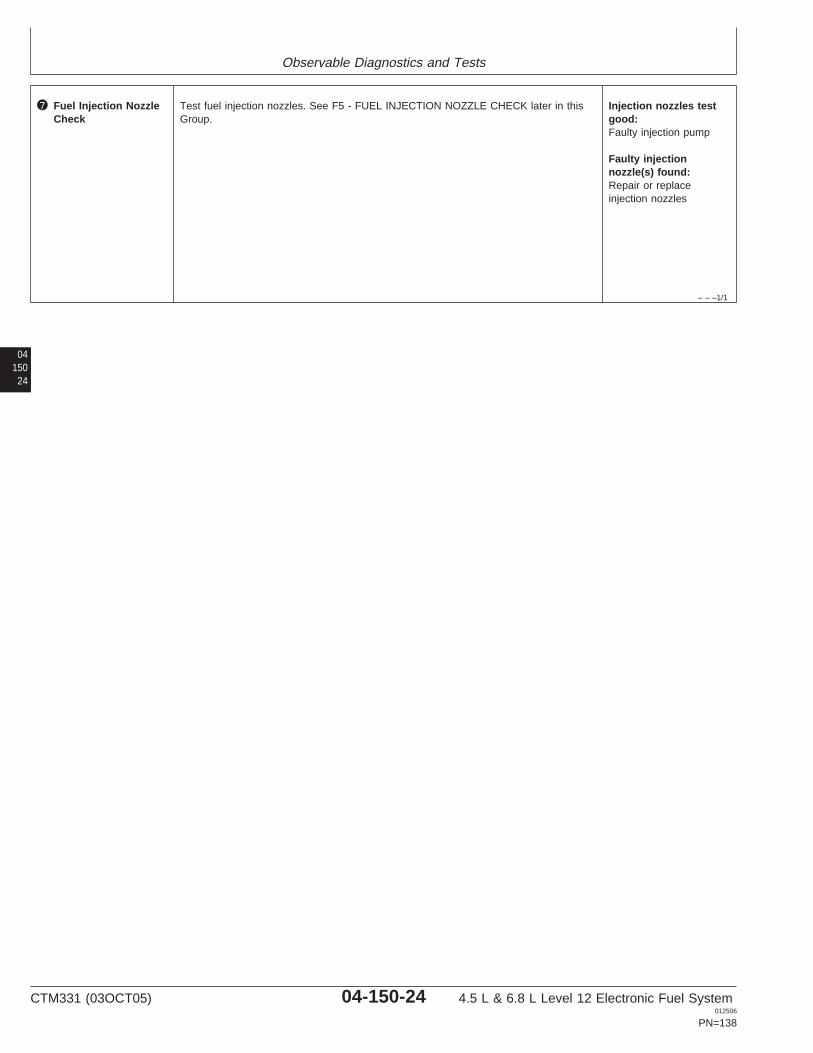
Observable Diagnostics and Tests
– – –1/1
7 Fuel Injection NozzleCheck
Test fuel injection nozzles. See F5 - FUEL INJECTION NOZZLE CHECK later in thisGroup.
Injection nozzles testgood:Faulty injection pump
Faulty injectionnozzle(s) found:Repair or replaceinjection nozzles
04150
24
CTM331 (03OCT05) 04-150-24 4.5 L & 6.8 L Level 12 Electronic Fuel System012506
PN=138
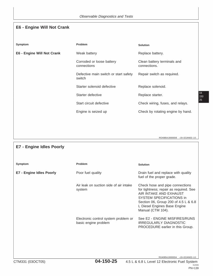
Observable Diagnostics and Tests
0415025
RG40854,00000D8 –19–02JAN02–1/1
E6 - Engine Will Not Crank
Symptom Problem Solution
E6 - Engine Will Not Crank Weak battery Replace battery.
Corroded or loose battery Clean battery terminals andconnections connections.
Defective main switch or start safety Repair switch as required.switch
Starter solenoid defective Replace solenoid.
Starter defective Replace starter.
Start circuit defective Check wiring, fuses, and relays.
Engine is seized up Check by rotating engine by hand.
RG40854,00000DA –19–02JAN02–1/1
E7 - Engine Idles Poorly
Symptom Problem Solution
E7 - Engine Idles Poorly Poor fuel quality Drain fuel and replace with qualityfuel of the proper grade.
Air leak on suction side of air intake Check hose and pipe connectionssystem for tightness; repair as required. See
AIR INTAKE AND EXHAUSTSYSTEM SPECIFICATIONS inSection 06, Group 200 of 4.5 L & 6.8L Diesel Engines Base EngineManual (CTM 104).
Electronic control system problem or See E2 - ENGINE MISFIRES/RUNSbasic engine problem IRREGULARLY DIAGNOSTIC
PROCEDURE earlier in this Group.
CTM331 (03OCT05) 04-150-25 4.5 L & 6.8 L Level 12 Electronic Fuel System012506
PN=139
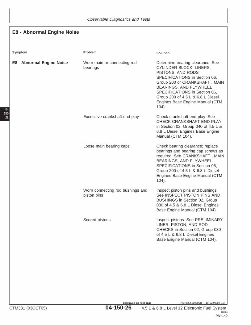
Observable Diagnostics and Tests
04150
26
RG40854,00000DB –19–02JAN02–1/2
E8 - Abnormal Engine Noise
Symptom Problem Solution
E8 - Abnormal Engine Noise Worn main or connecting rod Determine bearing clearance. Seebearings CYLINDER BLOCK, LINERS,
PISTONS, AND RODSSPECIFICATIONS in Section 06,Group 200 or CRANKSHAFT , MAINBEARINGS, AND FLYWHEELSPECIFICATIONS in Section 06,Group 200 of 4.5 L & 6.8 L DieselEngines Base Engine Manual (CTM104).
Excessive crankshaft end play Check crankshaft end play. SeeCHECK CRANKSHAFT END PLAYin Section 02, Group 040 of 4.5 L &6.8 L Diesel Engines Base EngineManual (CTM 104).
Loose main bearing caps Check bearing clearance; replacebearings and bearing cap screws asrequired. See CRANKSHAFT , MAINBEARINGS, AND FLYWHEELSPECIFICATIONS in Section 06,Group 200 of 4.5 L & 6.8 L DieselEngines Base Engine Manual (CTM104).
Worn connecting rod bushings and Inspect piston pins and bushings.piston pins See INSPECT PISTON PINS AND
BUSHINGS in Section 02, Group030 of 4.5 & 6.8 L Diesel EnginesBase Engine Manual (CTM 104).
Scored pistons Inspect pistons. See PRELIMINARYLINER, PISTON, AND RODCHECKS in Section 02, Group 030of 4.5 L & 6.8 L Diesel EnginesBase Engine Manual (CTM 104).
CTM331 (03OCT05) 04-150-26 4.5 L & 6.8 L Level 12 Electronic Fuel System012506
PN=140
Continued on next page
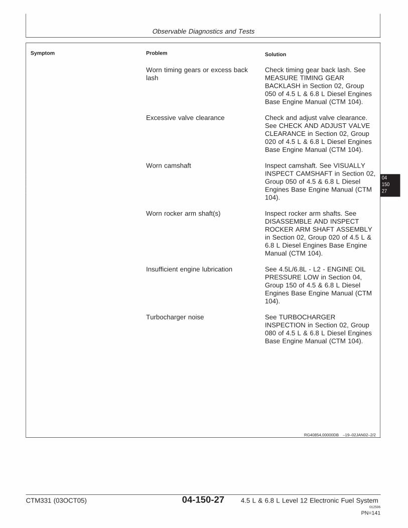
Observable Diagnostics and Tests
0415027
RG40854,00000DB –19–02JAN02–2/2
Symptom Problem Solution
Worn timing gears or excess back Check timing gear back lash. Seelash MEASURE TIMING GEAR
BACKLASH in Section 02, Group050 of 4.5 L & 6.8 L Diesel EnginesBase Engine Manual (CTM 104).
Excessive valve clearance Check and adjust valve clearance.See CHECK AND ADJUST VALVECLEARANCE in Section 02, Group020 of 4.5 L & 6.8 L Diesel EnginesBase Engine Manual (CTM 104).
Worn camshaft Inspect camshaft. See VISUALLYINSPECT CAMSHAFT in Section 02,Group 050 of 4.5 & 6.8 L DieselEngines Base Engine Manual (CTM104).
Worn rocker arm shaft(s) Inspect rocker arm shafts. SeeDISASSEMBLE AND INSPECTROCKER ARM SHAFT ASSEMBLYin Section 02, Group 020 of 4.5 L &6.8 L Diesel Engines Base EngineManual (CTM 104).
Insufficient engine lubrication See 4.5L/6.8L - L2 - ENGINE OILPRESSURE LOW in Section 04,Group 150 of 4.5 & 6.8 L DieselEngines Base Engine Manual (CTM104).
Turbocharger noise See TURBOCHARGERINSPECTION in Section 02, Group080 of 4.5 L & 6.8 L Diesel EnginesBase Engine Manual (CTM 104).
CTM331 (03OCT05) 04-150-27 4.5 L & 6.8 L Level 12 Electronic Fuel System012506
PN=141
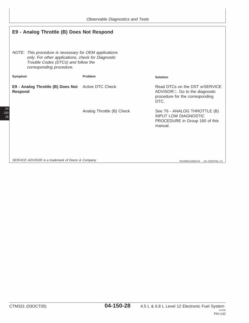
Observable Diagnostics and Tests
04150
28
RG40854,0000145 –19–23SEP05–1/1
E9 - Analog Throttle (B) Does Not Respond
NOTE: This procedure is necessary for OEM applicationsonly. For other applications, check for DiagnosticTrouble Codes (DTCs) and follow thecorresponding procedure.
Symptom Problem Solution
E9 - Analog Throttle (B) Does Not Active DTC Check Read DTCs on the DST orSERVICERespond ADVISOR. Go to the diagnostic
procedure for the correspondingDTC.
Analog Throttle (B) Check See T6 - ANALOG THROTTLE (B)INPUT LOW DIAGNOSTICPROCEDURE in Group 160 of thismanual.
SERVICE ADVISOR is a trademark of Deere & Company
CTM331 (03OCT05) 04-150-28 4.5 L & 6.8 L Level 12 Electronic Fuel System012506
PN=142
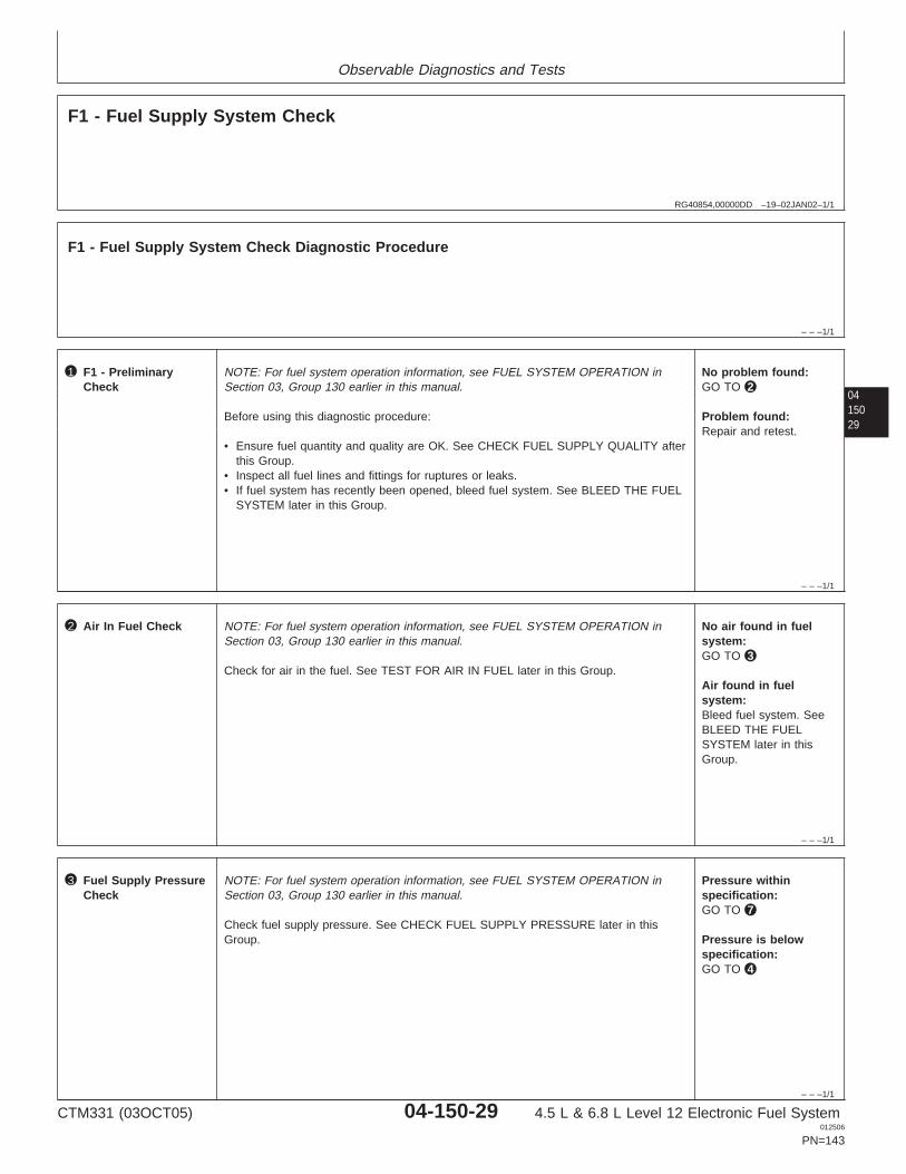
Observable Diagnostics and Tests
RG40854,00000DD –19–02JAN02–1/1
F1 - Fuel Supply System Check
– – –1/1
F1 - Fuel Supply System Check Diagnostic Procedure
0415029
– – –1/1
1 F1 - PreliminaryCheck
NOTE: For fuel system operation information, see FUEL SYSTEM OPERATION inSection 03, Group 130 earlier in this manual.
Before using this diagnostic procedure:
• Ensure fuel quantity and quality are OK. See CHECK FUEL SUPPLY QUALITY afterthis Group.
• Inspect all fuel lines and fittings for ruptures or leaks.• If fuel system has recently been opened, bleed fuel system. See BLEED THE FUEL
SYSTEM later in this Group.
No problem found:GO TO 2
Problem found:Repair and retest.
– – –1/1
2 Air In Fuel Check NOTE: For fuel system operation information, see FUEL SYSTEM OPERATION inSection 03, Group 130 earlier in this manual.
Check for air in the fuel. See TEST FOR AIR IN FUEL later in this Group.
No air found in fuelsystem:GO TO 3
Air found in fuelsystem:Bleed fuel system. SeeBLEED THE FUELSYSTEM later in thisGroup.
– – –1/1
3 Fuel Supply PressureCheck
NOTE: For fuel system operation information, see FUEL SYSTEM OPERATION inSection 03, Group 130 earlier in this manual.
Check fuel supply pressure. See CHECK FUEL SUPPLY PRESSURE later in thisGroup.
Pressure withinspecification:GO TO 7
Pressure is belowspecification:GO TO 4
CTM331 (03OCT05) 04-150-29 4.5 L & 6.8 L Level 12 Electronic Fuel System012506
PN=143
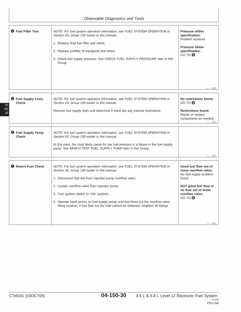
Observable Diagnostics and Tests
– – –1/1
4 Fuel Filter Test NOTE: For fuel system operation information, see FUEL SYSTEM OPERATION inSection 03, Group 130 earlier in this manual.
1. Replace final fuel filter and retest.
2. Replace prefilter (if equipped) and retest.
3. Check fuel supply pressure. See CHECK FUEL SUPPLY PRESSURE later in thisGroup.
Pressure withinspecification:Problem resolved
Pressure belowspecification:GO TO 5
04150
30
– – –1/1
5 Fuel Supply LinesCheck
NOTE: For fuel system operation information, see FUEL SYSTEM OPERATION inSection 03, Group 130 earlier in this manual.
Remove fuel supply lines and determine if there are any internal restrictions.
No restrictions found:GO TO 6
Restrictions found:Repair or replacecomponents as needed.
– – –1/1
6 Fuel Supply PumpCheck
NOTE: For fuel system operation information, see FUEL SYSTEM OPERATION inSection 03, Group 130 earlier in this manual.
At this point, the most likely cause for low fuel pressure is a failure in the fuel supplypump. See BENCH TEST FUEL SUPPLY PUMP later in this Group.
– – –1/1
7 Return Fuel Check NOTE: For fuel system operation information, see FUEL SYSTEM OPERATION inSection 03, Group 130 earlier in this manual.
1. Disconnect fuel line from injection pump overflow valve.
2. Loosen overflow valve from injection pump.
3. Turn ignition switch to “ON” position.
4. Operate hand primer on fuel supply pump until fuel flows out the overflow valvefitting location. If fuel flow out the hole cannot be obtained, retighten all fittings.
Good fuel flow out ofloose overflow valve:No fuel supply problemfound.
NOT good fuel flow orno flow out of looseoverflow valve:GO TO 8
CTM331 (03OCT05) 04-150-30 4.5 L & 6.8 L Level 12 Electronic Fuel System012506
PN=144
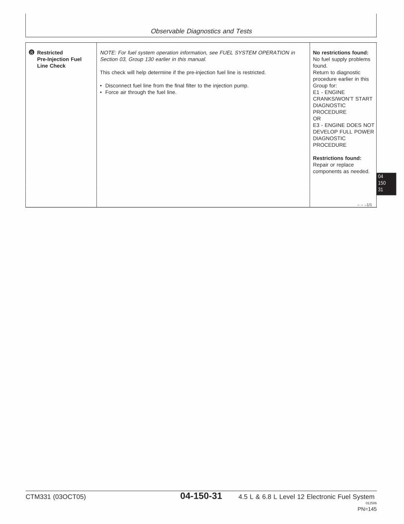
Observable Diagnostics and Tests
0415031
– – –1/1
8 RestrictedPre-Injection FuelLine Check
NOTE: For fuel system operation information, see FUEL SYSTEM OPERATION inSection 03, Group 130 earlier in this manual.
This check will help determine if the pre-injection fuel line is restricted.
• Disconnect fuel line from the final filter to the injection pump.• Force air through the fuel line.
No restrictions found:No fuel supply problemsfound.Return to diagnosticprocedure earlier in thisGroup for:E1 - ENGINECRANKS/WON’T STARTDIAGNOSTICPROCEDUREORE3 - ENGINE DOES NOTDEVELOP FULL POWERDIAGNOSTICPROCEDURE
Restrictions found:Repair or replacecomponents as needed.
CTM331 (03OCT05) 04-150-31 4.5 L & 6.8 L Level 12 Electronic Fuel System012506
PN=145
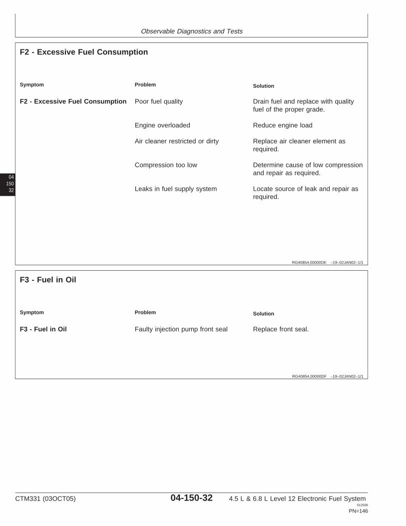
Observable Diagnostics and Tests
04150
32
RG40854,00000DE –19–02JAN02–1/1
F2 - Excessive Fuel Consumption
Symptom Problem Solution
F2 - Excessive Fuel Consumption Poor fuel quality Drain fuel and replace with qualityfuel of the proper grade.
Engine overloaded Reduce engine load
Air cleaner restricted or dirty Replace air cleaner element asrequired.
Compression too low Determine cause of low compressionand repair as required.
Leaks in fuel supply system Locate source of leak and repair asrequired.
RG40854,00000DF –19–02JAN02–1/1
F3 - Fuel in Oil
Symptom Problem Solution
F3 - Fuel in Oil Faulty injection pump front seal Replace front seal.
CTM331 (03OCT05) 04-150-32 4.5 L & 6.8 L Level 12 Electronic Fuel System012506
PN=146
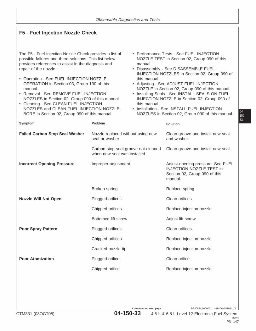
Observable Diagnostics and Tests
0415033
RG40854,0000001 –19–06MAR02–1/2
F5 - Fuel Injection Nozzle Check
The F5 - Fuel Injection Nozzle Check provides a list ofpossible failures and there solutions. This list belowprovides references to assist in the diagnosis andrepair of the nozzle.
• Operation - See FUEL INJECTION NOZZLEOPERATION in Section 03, Group 130 of thismanual.
• Removal - See REMOVE FUEL INJECTIONNOZZLES in Section 02, Group 090 of this manual.
• Cleaning - See CLEAN FUEL INJECTIONNOZZLES and CLEAN FUEL INJECTION NOZZLEBORE in Section 02, Group 090 of this manual.
• Performance Tests - See FUEL INJECTIONNOZZLE TEST in Section 02, Group 090 of thismanual.
• Disassembly - See DISASSEMBLE FUELINJECTION NOZZLES in Section 02, Group 090 ofthis manual.
• Adjusting - See ADJUST FUEL INJECTIONNOZZLE in Section 02, Group 090 of this manual.
• Installing Seals - See INSTALL SEALS ON FUELINJECTION NOZZLE in Section 02, Group 090 ofthis manual.
• Installation - See INSTALL FUEL INJECTIONNOZZLES in Section 02, Group 090 of this manual.
Symptom Problem Solution
Failed Carbon Stop Seal Washer Nozzle replaced without using new Clean groove and install new sealseal or washer and washer.
Carbon stop seal groove not cleaned Clean groove and install new seal.when new seal was installed.
Incorrect Opening Pressure Improper adjustment Adjust opening pressure. See FUELINJECTION NOZZLE TEST inSection 02, Group 090 of thismanual.
Broken spring Replace spring
Nozzle Will Not Open Plugged orifices Clean orifices.
Chipped orifices Replace injection nozzle
Bottomed lift screw Adjust lift screw.
Poor Spray Pattern Plugged orifices Clean orifices.
Chipped orifices Replace injection nozzle
Cracked nozzle tip Replace injection nozzle.
Poor Atomization Plugged orifice Clean orifice.
Chipped orifice Replace injection nozzle
CTM331 (03OCT05) 04-150-33 4.5 L & 6.8 L Level 12 Electronic Fuel System012506
PN=147
Continued on next page
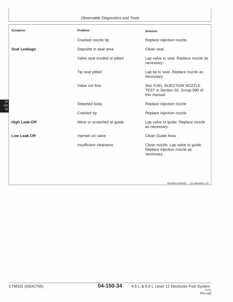
Observable Diagnostics and Tests
04150
34
RG40854,0000001 –19–06MAR02–2/2
Symptom Problem Solution
Cracked nozzle tip Replace injection nozzle.
Seat Leakage Deposits in seat area Clean seat.
Valve seat eroded or pitted Lap valve to seat. Replace nozzle asnecessary.
Tip seat pitted Lap tip to seat. Replace nozzle asnecessary.
Valve not free See FUEL INJECTION NOZZLETEST in Section 02, Group 090 ofthis manual.
Distorted body Replace injection nozzle
Cracked tip Replace injection nozzle
High Leak-Off Wear or scratched at guide Lap valve to guide. Replace nozzleas necessary.
Low Leak-Off Varnish on valve Clean Guide Area
Insufficient clearance Clean nozzle. Lap valve to guide.Replace injection nozzle asnecessary.
CTM331 (03OCT05) 04-150-34 4.5 L & 6.8 L Level 12 Electronic Fuel System012506
PN=148

Observable Diagnostics and Tests
0415035
CTM331 (03OCT05) 04-150-35 4.5 L & 6.8 L Level 12 Electronic Fuel System012506
PN=149
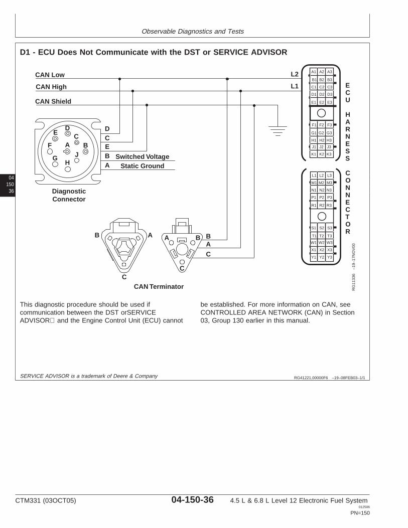
Observable Diagnostics and Tests
04150
36
RG41221,00000F6 –19–08FEB03–1/1
D1 - ECU Does Not Communicate with the DST or SERVICE ADVISOR
Y1 Y2 Y3
X3
W3
T3
S3
X2
W2
T2
S2
X1
W1
T1
S1
R1 R2 R3
P3
N3
M3
L3
P2
N2
M2
L2
P1
N1
M1
L1
A1 A2 A3
B3
C3
D3
E3
B2
C2
D2
E2
B1
C1
D1
E1
F1 F2 F3
G3
H3
J3
K3
G2
H2
J2
K2
G1
H1
J1
K1
CAN Low
CAN High
CAN Shield
BA
C
DCEBA
Switched Voltage
CAN Terminator
Static Ground
DiagnosticConnector
DC
BJ
HG
F
E
B A A B
CC
A
L2
L1 ECU
HARNESS
CONNECTOR
RG
1133
6–1
9–17
NO
V00
This diagnostic procedure should be used ifcommunication between the DST orSERVICEADVISOR and the Engine Control Unit (ECU) cannot
be established. For more information on CAN, seeCONTROLLED AREA NETWORK (CAN) in Section03, Group 130 earlier in this manual.
SERVICE ADVISOR is a trademark of Deere & Company
CTM331 (03OCT05) 04-150-36 4.5 L & 6.8 L Level 12 Electronic Fuel System012506
PN=150
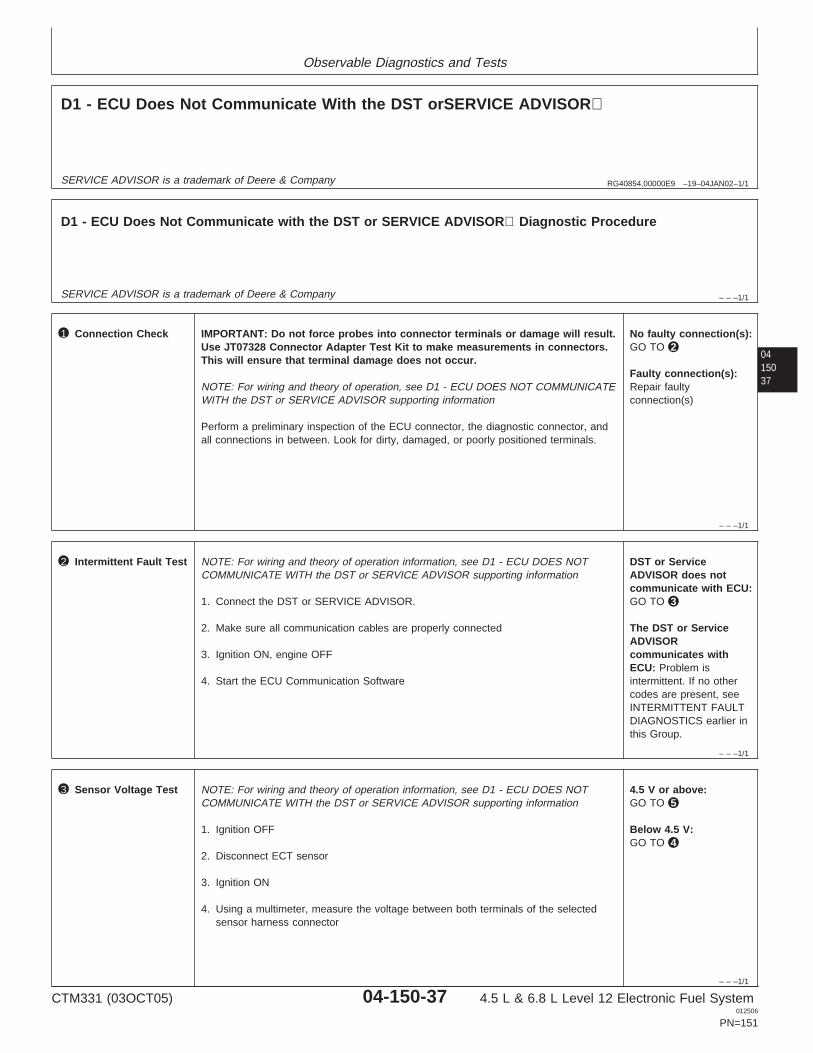
Observable Diagnostics and Tests
RG40854,00000E9 –19–04JAN02–1/1
D1 - ECU Does Not Communicate With the DST orSERVICE ADVISOR
SERVICE ADVISOR is a trademark of Deere & Company
– – –1/1
D1 - ECU Does Not Communicate with the DST or SERVICE ADVISOR Diagnostic Procedure
SERVICE ADVISOR is a trademark of Deere & Company
0415037
– – –1/1
1 Connection Check IMPORTANT: Do not force probes into connector terminals or damage will result.Use JT07328 Connector Adapter Test Kit to make measurements in connectors.This will ensure that terminal damage does not occur.
NOTE: For wiring and theory of operation, see D1 - ECU DOES NOT COMMUNICATEWITH the DST or SERVICE ADVISOR supporting information
Perform a preliminary inspection of the ECU connector, the diagnostic connector, andall connections in between. Look for dirty, damaged, or poorly positioned terminals.
No faulty connection(s):GO TO 2
Faulty connection(s):Repair faultyconnection(s)
– – –1/1
2 Intermittent Fault Test NOTE: For wiring and theory of operation information, see D1 - ECU DOES NOTCOMMUNICATE WITH the DST or SERVICE ADVISOR supporting information
1. Connect the DST or SERVICE ADVISOR.
2. Make sure all communication cables are properly connected
3. Ignition ON, engine OFF
4. Start the ECU Communication Software
DST or ServiceADVISOR does notcommunicate with ECU:GO TO 3
The DST or ServiceADVISORcommunicates withECU: Problem isintermittent. If no othercodes are present, seeINTERMITTENT FAULTDIAGNOSTICS earlier inthis Group.
– – –1/1
3 Sensor Voltage Test NOTE: For wiring and theory of operation information, see D1 - ECU DOES NOTCOMMUNICATE WITH the DST or SERVICE ADVISOR supporting information
1. Ignition OFF
2. Disconnect ECT sensor
3. Ignition ON
4. Using a multimeter, measure the voltage between both terminals of the selectedsensor harness connector
4.5 V or above:GO TO 5
Below 4.5 V:GO TO 4
CTM331 (03OCT05) 04-150-37 4.5 L & 6.8 L Level 12 Electronic Fuel System012506
PN=151
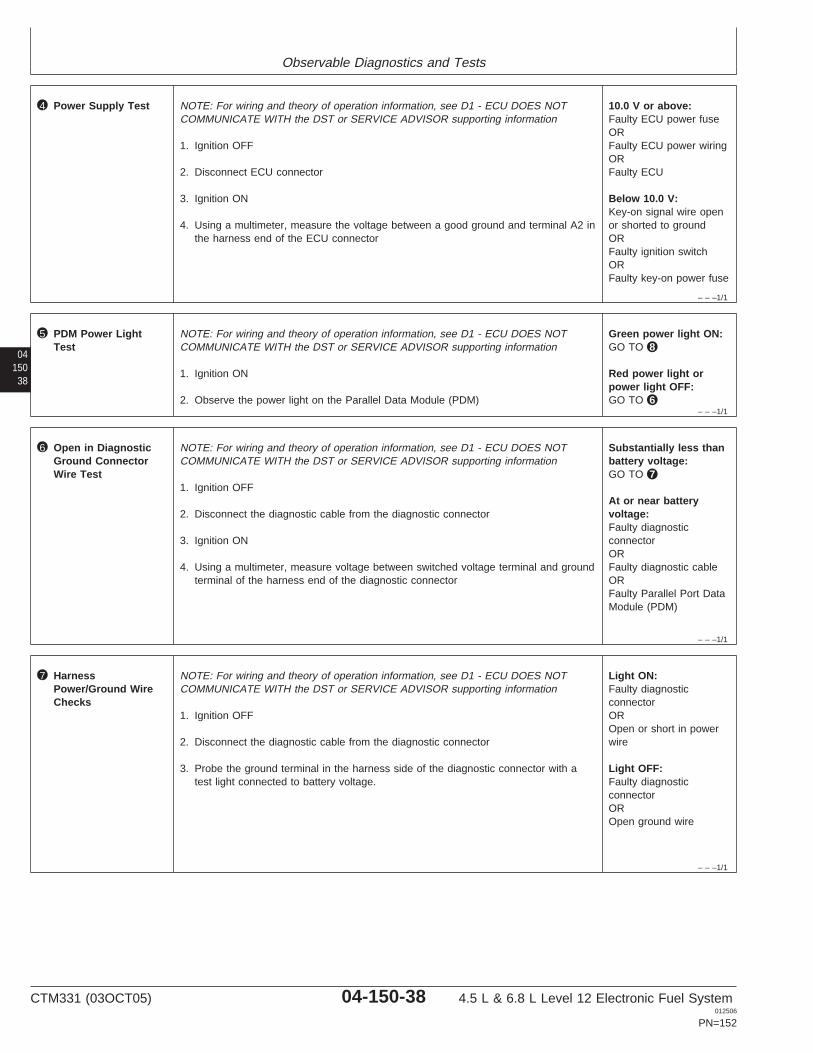
Observable Diagnostics and Tests
– – –1/1
4 Power Supply Test NOTE: For wiring and theory of operation information, see D1 - ECU DOES NOTCOMMUNICATE WITH the DST or SERVICE ADVISOR supporting information
1. Ignition OFF
2. Disconnect ECU connector
3. Ignition ON
4. Using a multimeter, measure the voltage between a good ground and terminal A2 inthe harness end of the ECU connector
10.0 V or above:Faulty ECU power fuseORFaulty ECU power wiringORFaulty ECU
Below 10.0 V:Key-on signal wire openor shorted to groundORFaulty ignition switchORFaulty key-on power fuse
04150
38
– – –1/1
5 PDM Power LightTest
NOTE: For wiring and theory of operation information, see D1 - ECU DOES NOTCOMMUNICATE WITH the DST or SERVICE ADVISOR supporting information
1. Ignition ON
2. Observe the power light on the Parallel Data Module (PDM)
Green power light ON:GO TO 8
Red power light orpower light OFF:GO TO 6
– – –1/1
6 Open in DiagnosticGround ConnectorWire Test
NOTE: For wiring and theory of operation information, see D1 - ECU DOES NOTCOMMUNICATE WITH the DST or SERVICE ADVISOR supporting information
1. Ignition OFF
2. Disconnect the diagnostic cable from the diagnostic connector
3. Ignition ON
4. Using a multimeter, measure voltage between switched voltage terminal and groundterminal of the harness end of the diagnostic connector
Substantially less thanbattery voltage:GO TO 7
At or near batteryvoltage:Faulty diagnosticconnectorORFaulty diagnostic cableORFaulty Parallel Port DataModule (PDM)
– – –1/1
7 HarnessPower/Ground WireChecks
NOTE: For wiring and theory of operation information, see D1 - ECU DOES NOTCOMMUNICATE WITH the DST or SERVICE ADVISOR supporting information
1. Ignition OFF
2. Disconnect the diagnostic cable from the diagnostic connector
3. Probe the ground terminal in the harness side of the diagnostic connector with atest light connected to battery voltage.
Light ON:Faulty diagnosticconnectorOROpen or short in powerwire
Light OFF:Faulty diagnosticconnectorOROpen ground wire
CTM331 (03OCT05) 04-150-38 4.5 L & 6.8 L Level 12 Electronic Fuel System012506
PN=152
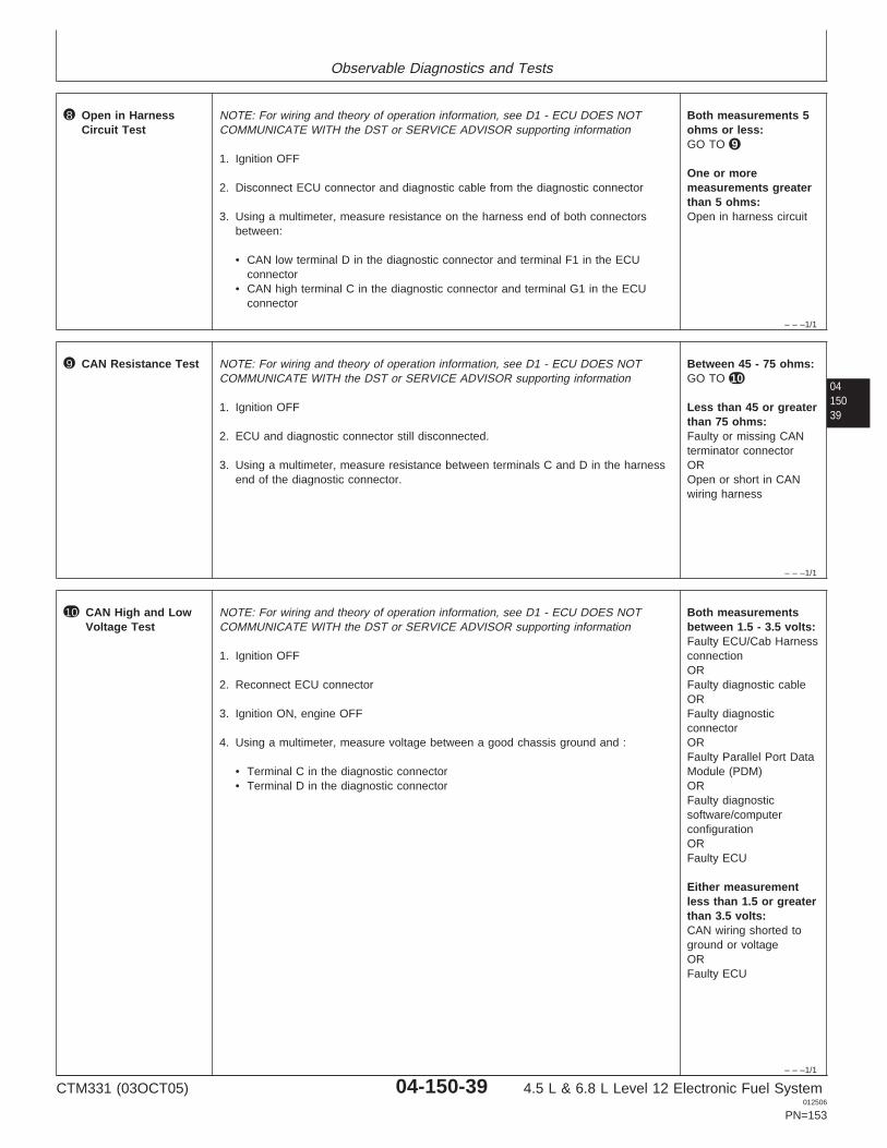
Observable Diagnostics and Tests
– – –1/1
8 Open in HarnessCircuit Test
NOTE: For wiring and theory of operation information, see D1 - ECU DOES NOTCOMMUNICATE WITH the DST or SERVICE ADVISOR supporting information
1. Ignition OFF
2. Disconnect ECU connector and diagnostic cable from the diagnostic connector
3. Using a multimeter, measure resistance on the harness end of both connectorsbetween:
• CAN low terminal D in the diagnostic connector and terminal F1 in the ECUconnector
• CAN high terminal C in the diagnostic connector and terminal G1 in the ECUconnector
Both measurements 5ohms or less:GO TO 9
One or moremeasurements greaterthan 5 ohms:Open in harness circuit
0415039
– – –1/1
9 CAN Resistance Test NOTE: For wiring and theory of operation information, see D1 - ECU DOES NOTCOMMUNICATE WITH the DST or SERVICE ADVISOR supporting information
1. Ignition OFF
2. ECU and diagnostic connector still disconnected.
3. Using a multimeter, measure resistance between terminals C and D in the harnessend of the diagnostic connector.
Between 45 - 75 ohms:GO TO 10
Less than 45 or greaterthan 75 ohms:Faulty or missing CANterminator connectorOROpen or short in CANwiring harness
– – –1/1
10 CAN High and LowVoltage Test
NOTE: For wiring and theory of operation information, see D1 - ECU DOES NOTCOMMUNICATE WITH the DST or SERVICE ADVISOR supporting information
1. Ignition OFF
2. Reconnect ECU connector
3. Ignition ON, engine OFF
4. Using a multimeter, measure voltage between a good chassis ground and :
• Terminal C in the diagnostic connector• Terminal D in the diagnostic connector
Both measurementsbetween 1.5 - 3.5 volts:Faulty ECU/Cab HarnessconnectionORFaulty diagnostic cableORFaulty diagnosticconnectorORFaulty Parallel Port DataModule (PDM)ORFaulty diagnosticsoftware/computerconfigurationORFaulty ECU
Either measurementless than 1.5 or greaterthan 3.5 volts:CAN wiring shorted toground or voltageORFaulty ECU
CTM331 (03OCT05) 04-150-39 4.5 L & 6.8 L Level 12 Electronic Fuel System012506
PN=153
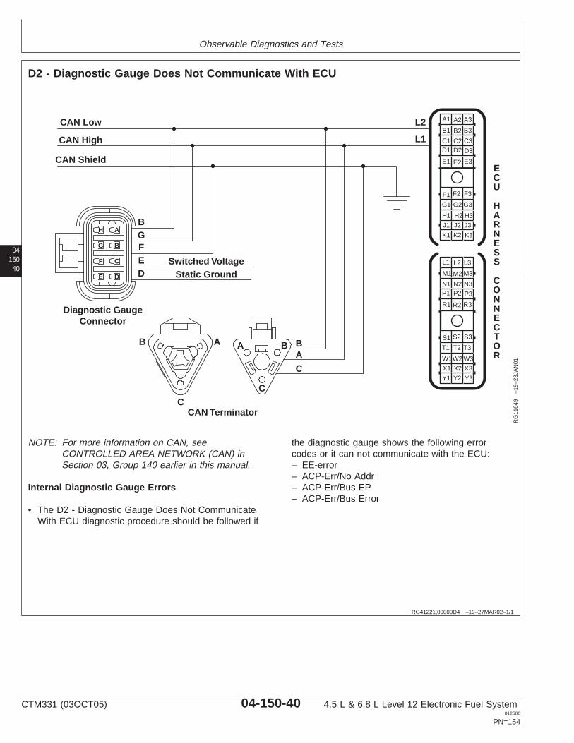
Observable Diagnostics and Tests
04150
40
RG41221,00000D4 –19–27MAR02–1/1
D2 - Diagnostic Gauge Does Not Communicate With ECU
ECU
HARNESS
CONNECTOR
F3F2F1
G1
H1
J1
K1
G2
H2
J2
K2
G3
H3
J3
K3
A3A2A1
B1
C1D1
E1
B2
C2D2
E2
B3
C3
D3
E3
S3S2S1
T1
X1
T2
X2
T3
X3
Y1 Y2 Y3
L3L2L1
N1 N2 N3
CAN Low L2
L1
BA
C
BGFED
Switched VoltageStatic Ground
Diagnostic GaugeConnector
CAN High
CAN Shield
B A A B
CC
CAN Terminator
AH
BG
CF
DE M3M2M1
R3R2R1
P3P2P1
W3W2W1
RG
1164
9–1
9–23
JAN
01
NOTE: For more information on CAN, seeCONTROLLED AREA NETWORK (CAN) inSection 03, Group 140 earlier in this manual.
Internal Diagnostic Gauge Errors
• The D2 - Diagnostic Gauge Does Not CommunicateWith ECU diagnostic procedure should be followed if
the diagnostic gauge shows the following errorcodes or it can not communicate with the ECU:– EE-error– ACP-Err/No Addr– ACP-Err/Bus EP– ACP-Err/Bus Error
CTM331 (03OCT05) 04-150-40 4.5 L & 6.8 L Level 12 Electronic Fuel System012506
PN=154
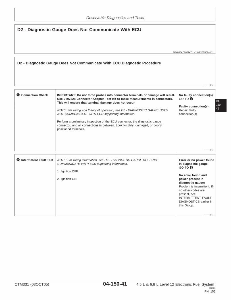
Observable Diagnostics and Tests
RG40854,0000147 –19–11FEB02–1/1
D2 - Diagnostic Gauge Does Not Communicate With ECU
– – –1/1
D2 - Diagnostic Gauge Does Not Communicate With ECU Diagnostic Procedure
0415041
– – –1/1
1 Connection Check IMPORTANT: Do not force probes into connector terminals or damage will result.Use JT07328 Connector Adapter Test Kit to make measurements in connectors.This will ensure that terminal damage does not occur.
NOTE: For wiring and theory of operation, see D2 - DIAGNOSTIC GAUGE DOESNOT COMMUNICATE WITH ECU supporting information.
Perform a preliminary inspection of the ECU connector, the diagnostic gaugeconnector, and all connections in between. Look for dirty, damaged, or poorlypositioned terminals.
No faulty connection(s):GO TO 2
Faulty connection(s):Repair faultyconnection(s)
– – –1/1
2 Intermittent Fault Test NOTE: For wiring information, see D2 - DIAGNOSTIC GAUGE DOES NOTCOMMUNICATE WITH ECU supporting information.
1. Ignition OFF
2. Ignition ON
Error or no power foundin diagnostic gauge:GO TO 3
No error found andpower present indiagnostic gauge:Problem is intermittent. Ifno other codes arepresent, seeINTERMITTENT FAULTDIAGNOSTICS earlier inthis Group.
CTM331 (03OCT05) 04-150-41 4.5 L & 6.8 L Level 12 Electronic Fuel System012506
PN=155
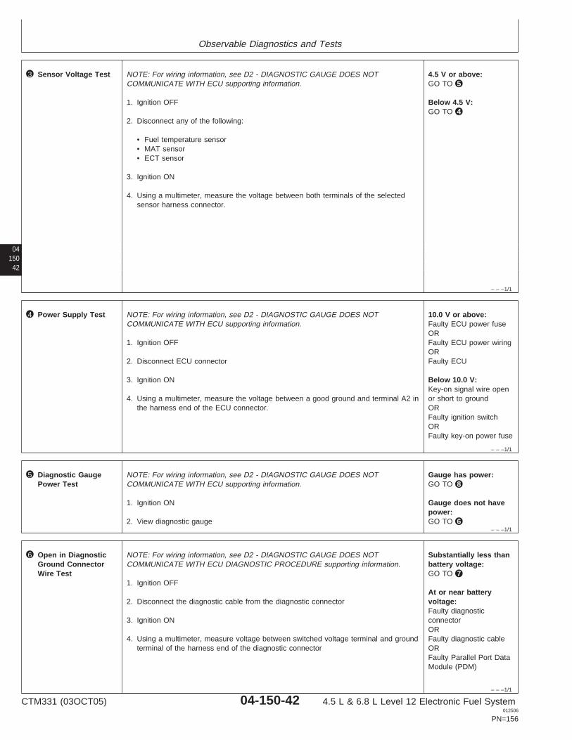
Observable Diagnostics and Tests
04150
42
– – –1/1
3 Sensor Voltage Test NOTE: For wiring information, see D2 - DIAGNOSTIC GAUGE DOES NOTCOMMUNICATE WITH ECU supporting information.
1. Ignition OFF
2. Disconnect any of the following:
• Fuel temperature sensor• MAT sensor• ECT sensor
3. Ignition ON
4. Using a multimeter, measure the voltage between both terminals of the selectedsensor harness connector.
4.5 V or above:GO TO 5
Below 4.5 V:GO TO 4
– – –1/1
4 Power Supply Test NOTE: For wiring information, see D2 - DIAGNOSTIC GAUGE DOES NOTCOMMUNICATE WITH ECU supporting information.
1. Ignition OFF
2. Disconnect ECU connector
3. Ignition ON
4. Using a multimeter, measure the voltage between a good ground and terminal A2 inthe harness end of the ECU connector.
10.0 V or above:Faulty ECU power fuseORFaulty ECU power wiringORFaulty ECU
Below 10.0 V:Key-on signal wire openor short to groundORFaulty ignition switchORFaulty key-on power fuse
– – –1/1
5 Diagnostic GaugePower Test
NOTE: For wiring information, see D2 - DIAGNOSTIC GAUGE DOES NOTCOMMUNICATE WITH ECU supporting information.
1. Ignition ON
2. View diagnostic gauge
Gauge has power:GO TO 8
Gauge does not havepower:GO TO 6
– – –1/1
6 Open in DiagnosticGround ConnectorWire Test
NOTE: For wiring information, see D2 - DIAGNOSTIC GAUGE DOES NOTCOMMUNICATE WITH ECU DIAGNOSTIC PROCEDURE supporting information.
1. Ignition OFF
2. Disconnect the diagnostic cable from the diagnostic connector
3. Ignition ON
4. Using a multimeter, measure voltage between switched voltage terminal and groundterminal of the harness end of the diagnostic connector
Substantially less thanbattery voltage:GO TO 7
At or near batteryvoltage:Faulty diagnosticconnectorORFaulty diagnostic cableORFaulty Parallel Port DataModule (PDM)
CTM331 (03OCT05) 04-150-42 4.5 L & 6.8 L Level 12 Electronic Fuel System012506
PN=156
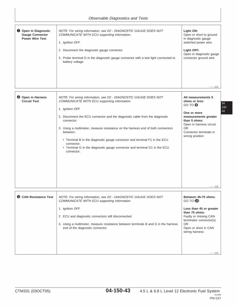
Observable Diagnostics and Tests
– – –1/1
7 Open in DiagnosticGauge ConnectorPower Wire Test
NOTE: For wiring information, see D2 - DIAGNOSTIC GAUGE DOES NOTCOMMUNICATE WITH ECU supporting information.
1. Ignition OFF
2. Disconnect the diagnostic gauge connector
3. Probe terminal D in the diagnostic gauge connector with a test light connected tobattery voltage.
Light ON:Open or short to groundin diagnostic gaugeswitched power wire.
Light OFF:Open in diagnostic gaugeconnector ground wire.
0415043
– – –1/1
8 Open in HarnessCircuit Test
NOTE: For wiring information, see D2 - DIAGNOSTIC GAUGE DOES NOTCOMMUNICATE WITH ECU supporting information.
1. Ignition OFF
2. Disconnect the ECU connector and the diagnostic cable from the diagnosticconnector.
3. Using a multimeter, measure resistance on the harness end of both connectorsbetween:
• Terminal B in the diagnostic gauge connector and terminal F1 in the ECUconnector.
• Terminal G in the diagnostic gauge connector and terminal G1 in the ECUconnector.
All measurements 5ohms or less:GO TO 9
One or moremeasurements greaterthan 5 ohms:Open in harness circuitORConnector terminals inwrong position
– – –1/1
9 CAN Resistance Test NOTE: For wiring information, see D2 - DIAGNOSTIC GAUGE DOES NOTCOMMUNICATE WITH ECU supporting information.
1. Ignition OFF
2. ECU and diagnostic connectors still disconnected.
3. Using a multimeter, measure resistance between terminals B and G in the harnessend of the diagnostic connector.
Between 45-75 ohms:GO TO 10
Less than 45 or greaterthan 75 ohms:Faulty or missing CANterminator connector(s)OROpen or short in CANwiring harness
CTM331 (03OCT05) 04-150-43 4.5 L & 6.8 L Level 12 Electronic Fuel System012506
PN=157
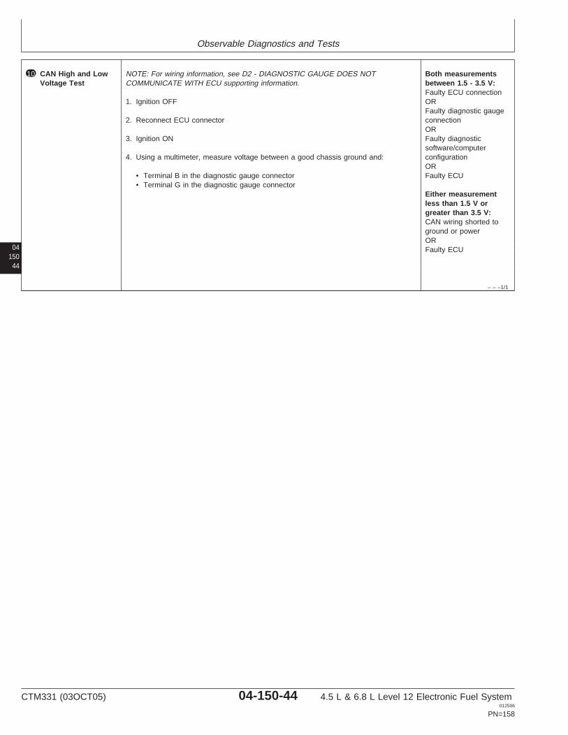
Observable Diagnostics and Tests
04150
44
– – –1/1
10 CAN High and LowVoltage Test
NOTE: For wiring information, see D2 - DIAGNOSTIC GAUGE DOES NOTCOMMUNICATE WITH ECU supporting information.
1. Ignition OFF
2. Reconnect ECU connector
3. Ignition ON
4. Using a multimeter, measure voltage between a good chassis ground and:
• Terminal B in the diagnostic gauge connector• Terminal G in the diagnostic gauge connector
Both measurementsbetween 1.5 - 3.5 V:Faulty ECU connectionORFaulty diagnostic gaugeconnectionORFaulty diagnosticsoftware/computerconfigurationORFaulty ECU
Either measurementless than 1.5 V orgreater than 3.5 V:CAN wiring shorted toground or powerORFaulty ECU
CTM331 (03OCT05) 04-150-44 4.5 L & 6.8 L Level 12 Electronic Fuel System012506
PN=158

Observable Diagnostics and Tests
0415045
CTM331 (03OCT05) 04-150-45 4.5 L & 6.8 L Level 12 Electronic Fuel System012506
PN=159
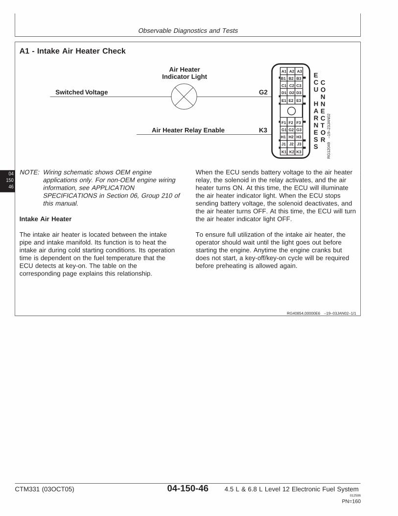
Observable Diagnostics and Tests
04150
46
RG40854,00000E6 –19–03JAN02–1/1
A1 - Intake Air Heater Check
Switched Voltage
Air HeaterIndicator Light
Air Heater Relay Enable
G2
K3
K1 K2 K3
J3
H3
G3
F3
J2
H2
G2
F2
J1
H1
G1
F1
E1 E2 E3
D3
C3
B3
A3
D2
C2
B2
A2
D1
C1
B1
A1
CONNECTOR
ECU
HARNESS
RG
1204
9–1
9–23
JAN
02
NOTE: Wiring schematic shows OEM engineapplications only. For non-OEM engine wiringinformation, see APPLICATIONSPECIFICATIONS in Section 06, Group 210 ofthis manual.
Intake Air Heater
The intake air heater is located between the intakepipe and intake manifold. Its function is to heat theintake air during cold starting conditions. Its operationtime is dependent on the fuel temperature that theECU detects at key-on. The table on thecorresponding page explains this relationship.
When the ECU sends battery voltage to the air heaterrelay, the solenoid in the relay activates, and the airheater turns ON. At this time, the ECU will illuminatethe air heater indicator light. When the ECU stopssending battery voltage, the solenoid deactivates, andthe air heater turns OFF. At this time, the ECU will turnthe air heater indicator light OFF.
To ensure full utilization of the intake air heater, theoperator should wait until the light goes out beforestarting the engine. Anytime the engine cranks butdoes not start, a key-off/key-on cycle will be requiredbefore preheating is allowed again.
CTM331 (03OCT05) 04-150-46 4.5 L & 6.8 L Level 12 Electronic Fuel System012506
PN=160
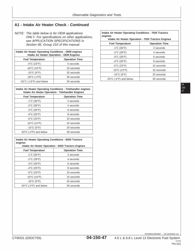
Observable Diagnostics and Tests
0415047
RG40854,00000E7 –19–04JAN02–1/1
A1 - Intake Air Heater Check - Continued
NOTE: The table below is for OEM applicationsONLY. For specifications on other applications,see APPLICATION SPECIFICATIONS inSection 06, Group 210 of this manual.
Intake Air Heater Operating Conditions - OEM enginesIntake Air Heater Operation - OEM Engines
Fuel Temperature Operation Time
-5°C (23°F) 5 seconds
-10°C (14°F) 15 seconds
-15°C (5°F) 20 seconds
-20°C (-4°F) 30 seconds
-25°C (-13°F) and below 30 seconds
Intake Air Heater Operating Conditions - Telehandler enginesIntake Air Heater Operation - Telehandler Engines
Fuel Temperature Operation Time
-1°C (30°F) 2 seconds
-2°C (28°F) 4 seconds
-3°C (26°F) 6 seconds
-4°C (25°F) 8 seconds
-5°C (23°F) 10 seconds
-10°C (14°F) 15 seconds
-15°C (5°F) 20 seconds
-20°C (-4°F) and below 30 seconds
Intake Air Heater Operating Conditions - 6020 Tractorsengines
Intake Air Heater Operation - 6020 Tractors Engines
Fuel Temperature Operation Time
-1°C (30°F) 2 seconds
-2°C (28°F) 4 seconds
-3°C (26°F) 6 seconds
-4°C (25°F) 8 seconds
-5°C (23°F) 10 seconds
-10°C (14°F) 15 seconds
-15°C (5°F) 20 seconds
-20°C (-4°F) and below 30 seconds
Intake Air Heater Operating Conditions - 7020 Tractorsengines
Intake Air Heater Operation - 7020 Tractors Engines
Fuel Temperature Operation Time
-1°C (30°F) 2 seconds
-2°C (28°F) 4 seconds
-3°C (26°F) 6 seconds
-4°C (25°F) 8 seconds
-5°C (23°F) 10 seconds
-10°C (14°F) 15 seconds
-15°C (5°F) 20 seconds
-20°C (-4°F) and below 30 seconds
CTM331 (03OCT05) 04-150-47 4.5 L & 6.8 L Level 12 Electronic Fuel System012506
PN=161
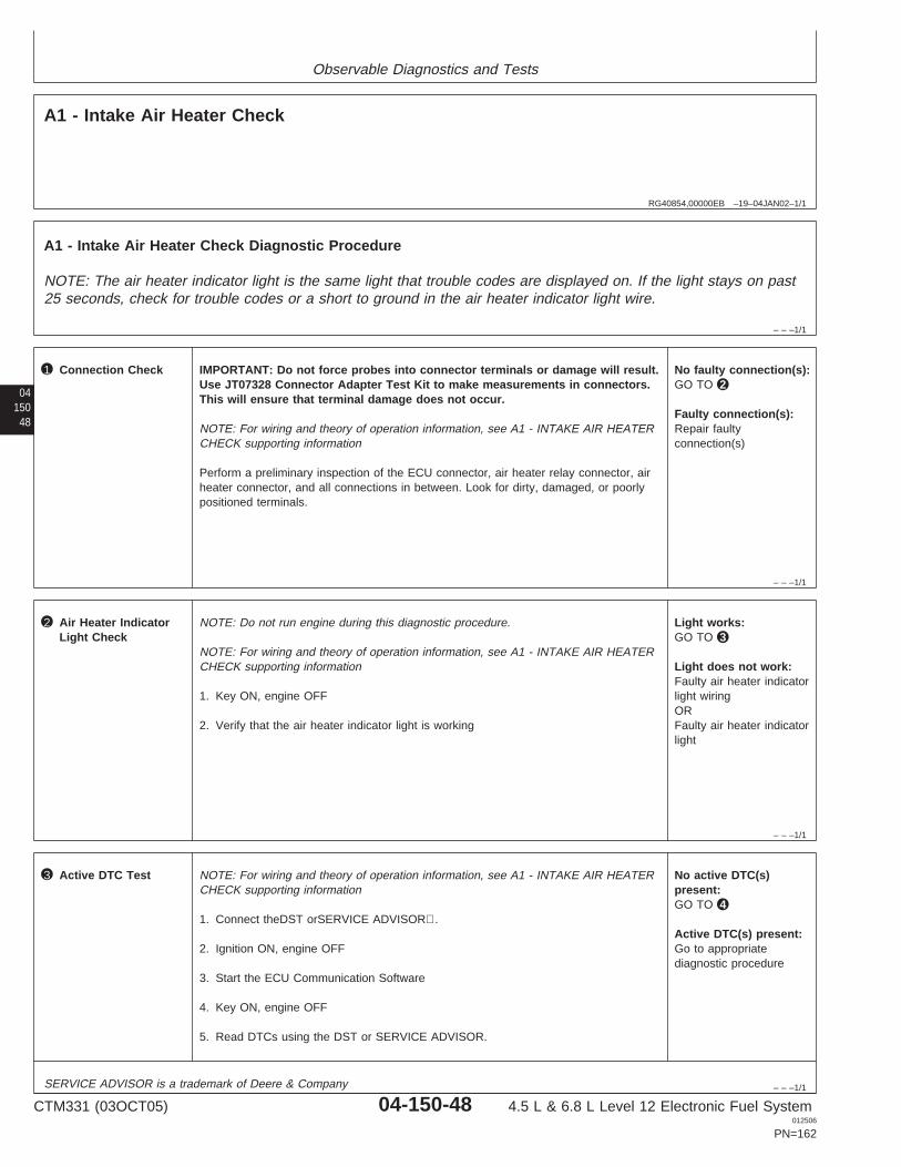
Observable Diagnostics and Tests
RG40854,00000EB –19–04JAN02–1/1
A1 - Intake Air Heater Check
– – –1/1
A1 - Intake Air Heater Check Diagnostic Procedure
NOTE: The air heater indicator light is the same light that trouble codes are displayed on. If the light stays on past25 seconds, check for trouble codes or a short to ground in the air heater indicator light wire.
04150
48
– – –1/1
1 Connection Check IMPORTANT: Do not force probes into connector terminals or damage will result.Use JT07328 Connector Adapter Test Kit to make measurements in connectors.This will ensure that terminal damage does not occur.
NOTE: For wiring and theory of operation information, see A1 - INTAKE AIR HEATERCHECK supporting information
Perform a preliminary inspection of the ECU connector, air heater relay connector, airheater connector, and all connections in between. Look for dirty, damaged, or poorlypositioned terminals.
No faulty connection(s):GO TO 2
Faulty connection(s):Repair faultyconnection(s)
– – –1/1
2 Air Heater IndicatorLight Check
NOTE: Do not run engine during this diagnostic procedure.
NOTE: For wiring and theory of operation information, see A1 - INTAKE AIR HEATERCHECK supporting information
1. Key ON, engine OFF
2. Verify that the air heater indicator light is working
Light works:GO TO 3
Light does not work:Faulty air heater indicatorlight wiringORFaulty air heater indicatorlight
– – –1/1
3 Active DTC Test NOTE: For wiring and theory of operation information, see A1 - INTAKE AIR HEATERCHECK supporting information
1. Connect theDST orSERVICE ADVISOR.
2. Ignition ON, engine OFF
3. Start the ECU Communication Software
4. Key ON, engine OFF
5. Read DTCs using the DST or SERVICE ADVISOR.
No active DTC(s)present:GO TO 4
Active DTC(s) present:Go to appropriatediagnostic procedure
SERVICE ADVISOR is a trademark of Deere & Company
CTM331 (03OCT05) 04-150-48 4.5 L & 6.8 L Level 12 Electronic Fuel System012506
PN=162
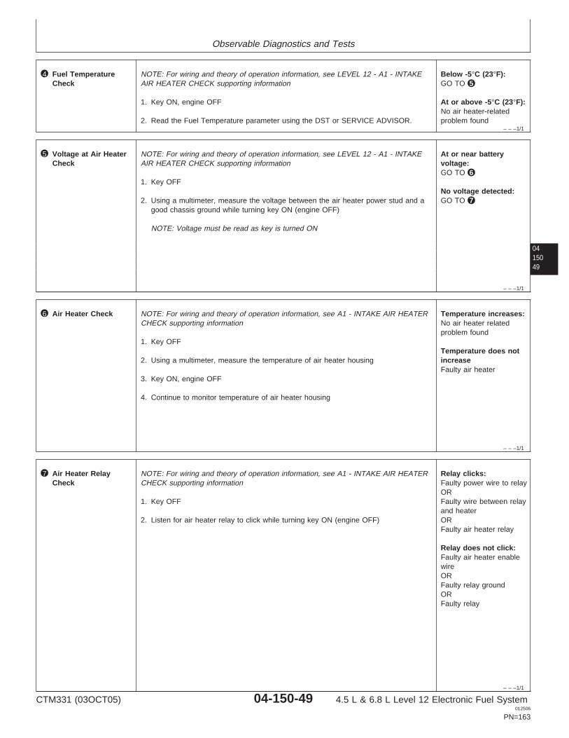
Observable Diagnostics and Tests
– – –1/1
4 Fuel TemperatureCheck
NOTE: For wiring and theory of operation information, see LEVEL 12 - A1 - INTAKEAIR HEATER CHECK supporting information
1. Key ON, engine OFF
2. Read the Fuel Temperature parameter using the DST or SERVICE ADVISOR.
Below -5°C (23°F):GO TO 5
At or above -5°C (23°F):No air heater-relatedproblem found
0415049
– – –1/1
5 Voltage at Air HeaterCheck
NOTE: For wiring and theory of operation information, see LEVEL 12 - A1 - INTAKEAIR HEATER CHECK supporting information
1. Key OFF
2. Using a multimeter, measure the voltage between the air heater power stud and agood chassis ground while turning key ON (engine OFF)
NOTE: Voltage must be read as key is turned ON
At or near batteryvoltage:GO TO 6
No voltage detected:GO TO 7
– – –1/1
6 Air Heater Check NOTE: For wiring and theory of operation information, see A1 - INTAKE AIR HEATERCHECK supporting information
1. Key OFF
2. Using a multimeter, measure the temperature of air heater housing
3. Key ON, engine OFF
4. Continue to monitor temperature of air heater housing
Temperature increases:No air heater relatedproblem found
Temperature does notincreaseFaulty air heater
– – –1/1
7 Air Heater RelayCheck
NOTE: For wiring and theory of operation information, see A1 - INTAKE AIR HEATERCHECK supporting information
1. Key OFF
2. Listen for air heater relay to click while turning key ON (engine OFF)
Relay clicks:Faulty power wire to relayORFaulty wire between relayand heaterORFaulty air heater relay
Relay does not click:Faulty air heater enablewireORFaulty relay groundORFaulty relay
CTM331 (03OCT05) 04-150-49 4.5 L & 6.8 L Level 12 Electronic Fuel System012506
PN=163
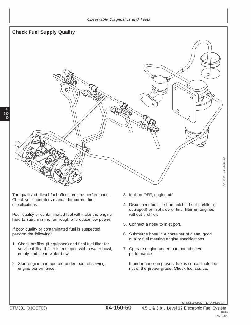
Observable Diagnostics and Tests
04150
50
RG40854,00000EC –19–04JAN02–1/1
Check Fuel Supply Quality
RG
1196
9–U
N–2
3JA
N02
The quality of diesel fuel affects engine performance.Check your operators manual for correct fuelspecifications.
Poor quality or contaminated fuel will make the enginehard to start, misfire, run rough or produce low power.
If poor quality or contaminated fuel is suspected,perform the following:
1. Check prefilter (if equipped) and final fuel filter forserviceability. If filter is equipped with a water bowl,empty and clean water bowl.
2. Start engine and operate under load, observingengine performance.
3. Ignition OFF, engine off
4. Disconnect fuel line from inlet side of prefilter (ifequipped) or inlet side of final filter on engineswithout prefilter.
5. Connect a hose to inlet port.
6. Submerge hose in a container of clean, goodquality fuel meeting engine specifications.
7. Operate engine under load and observeperformance.
If performance improves, fuel is contaminated ornot of the proper grade. Check fuel source.
CTM331 (03OCT05) 04-150-50 4.5 L & 6.8 L Level 12 Electronic Fuel System012506
PN=164
Observable Diagnostics and Tests
0415051
RG40854,00000EE –19–04JAN02–1/1
Test for Fuel Drain Back
Fuel draining back through the fuel system may causehard starting. This procedure will determine if air isentering the system at connections and allowing fuel tosiphon back to the fuel tank.
1. Disconnect fuel supply and return lines at fuel tank.
IMPORTANT: Fuel return line MUST extend below fuellevel in fuel tank before performing thistest. Fill fuel tank if necessary.
2. Drain all fuel from the system, including the fuel supplypump, fuel injection pump, fuel filters, and water bowl(if equipped).
3. Securely plug off the end of the fuel return pipe.
CAUTION: Maximum air pressure should be 100kPa (1 bar) (14.5 psi) when performing this test.
4. Using a low pressure air source, pressurize the fuelsystem at the fuel supply line.
5. Apply liquid soap and water solution to all joints andconnections in the fuel system and inspect for leaks.
NOTE: Connections may allow air to enter the systemwithout allowing fuel to leak out.
6. If any leaks are found, take necessary steps to repair.
7. Reconnect supply and return lines and prime system.
8. Start engine and run for approximately 10 minutes.
9. Allow engine to sit overnight and try starting thefollowing morning.
CTM331 (03OCT05) 04-150-51 4.5 L & 6.8 L Level 12 Electronic Fuel System012506
PN=165
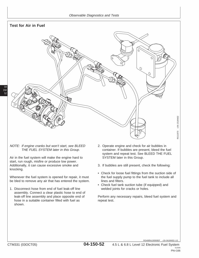
Observable Diagnostics and Tests
04150
52
RG40854,00000EF –19–04JAN02–1/1
Test for Air in Fuel
RG
1197
0–U
N–2
3JA
N02
NOTE: If engine cranks but won’t start, see BLEEDTHE FUEL SYSTEM later in this Group.
Air in the fuel system will make the engine hard tostart, run rough, misfire or produce low power.Additionally, it can cause excessive smoke andknocking.
Whenever the fuel system is opened for repair, it mustbe bled to remove any air that has entered the system.
1. Disconnect hose from end of fuel leak-off lineassembly. Connect a clear plastic hose to end ofleak-off line assembly and place opposite end ofhose in a suitable container filled with fuel asshown.
2. Operate engine and check for air bubbles incontainer. If bubbles are present, bleed the fuelsystem and repeat test. See BLEED THE FUELSYSTEM later in this Group.
3. If bubbles are still present, check the following:
• Check for loose fuel fittings from the suction side ofthe fuel supply pump to the fuel tank to include alllines and filters.
• Check fuel tank suction tube (if equipped) andwelded joints for cracks or holes.
Perform any necessary repairs, bleed fuel system andrepeat test.
CTM331 (03OCT05) 04-150-52 4.5 L & 6.8 L Level 12 Electronic Fuel System012506
PN=166
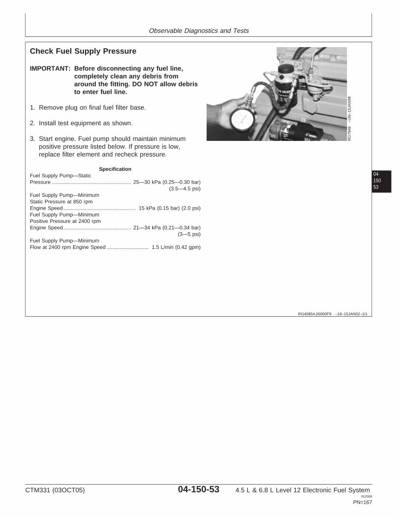
Observable Diagnostics and Tests
0415053
RG40854,00000F9 –19–15JAN02–1/1
Check Fuel Supply Pressure
RG
7946
–UN
–15J
AN
98
IMPORTANT: Before disconnecting any fuel line,completely clean any debris fromaround the fitting. DO NOT allow debristo enter fuel line.
1. Remove plug on final fuel filter base.
2. Install test equipment as shown.
3. Start engine. Fuel pump should maintain minimumpositive pressure listed below. If pressure is low,replace filter element and recheck pressure.
SpecificationFuel Supply Pump—StaticPressure 25—30 kPa (0.25—0.30 bar)
(3.5—4.5 psi).......................................................
Fuel Supply Pump—MinimumStatic Pressure at 850 rpmEngine Speed 15 kPa (0.15 bar) (2.0 psi)..................................................Fuel Supply Pump—MinimumPositive Pressure at 2400 rpmEngine Speed 21—34 kPa (0.21—0.34 bar)
(3—5 psi)...............................................
Fuel Supply Pump—MinimumFlow at 2400 rpm Engine Speed 1.5 L/min (0.42 gpm).............................
CTM331 (03OCT05) 04-150-53 4.5 L & 6.8 L Level 12 Electronic Fuel System012506
PN=167
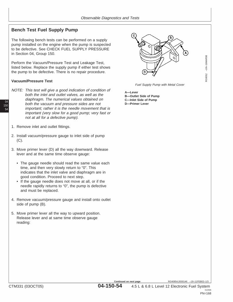
Observable Diagnostics and Tests
04150
54
RG40854,0000146 –19–11FEB02–1/3
Bench Test Fuel Supply Pump
RG
9052
–UN
–16M
AR
98
Fuel Supply Pump with Metal Cover
A—LeverB—Outlet Side of PumpC—Inlet Side of PumpD—Primer Lever
The following bench tests can be performed on a supplypump installed on the engine when the pump is suspectedto be defective. See CHECK FUEL SUPPLY PRESSUREin Section 04, Group 150.
Perform the Vacuum/Pressure Test and Leakage Test,listed below. Replace the supply pump if either test showsthe pump to be defective. There is no repair procedure.
Vacuum/Pressure Test
NOTE: This test will give a good indication of condition ofboth the inlet and outlet valves, as well as thediaphragm. The numerical values obtained onboth the vacuum and pressure sides are notimportant; rather it is the needle movement that isimportant (very slow for a good pump; very fast ornot at all for a defective pump).
1. Remove inlet and outlet fittings.
2. Install vacuum/pressure gauge to inlet side of pump(C).
3. Move primer lever (D) all the way downward. Releaselever and at the same time observe gauge:
• The gauge needle should read the same value eachtime, and then very slowly return to “0”. Thisindicates that the inlet valve and diaphragm are ingood condition. Proceed to next step.
• If the gauge needle does not move at all, or if theneedle rapidly returns to “0”, the pump is defectiveand must be replaced.
4. Remove vacuum/pressure gauge and install onto outletside of pump (B).
5. Move primer lever all the way to upward position.Release lever and at same time observe gaugereading:
CTM331 (03OCT05) 04-150-54 4.5 L & 6.8 L Level 12 Electronic Fuel System012506
PN=168
Continued on next page
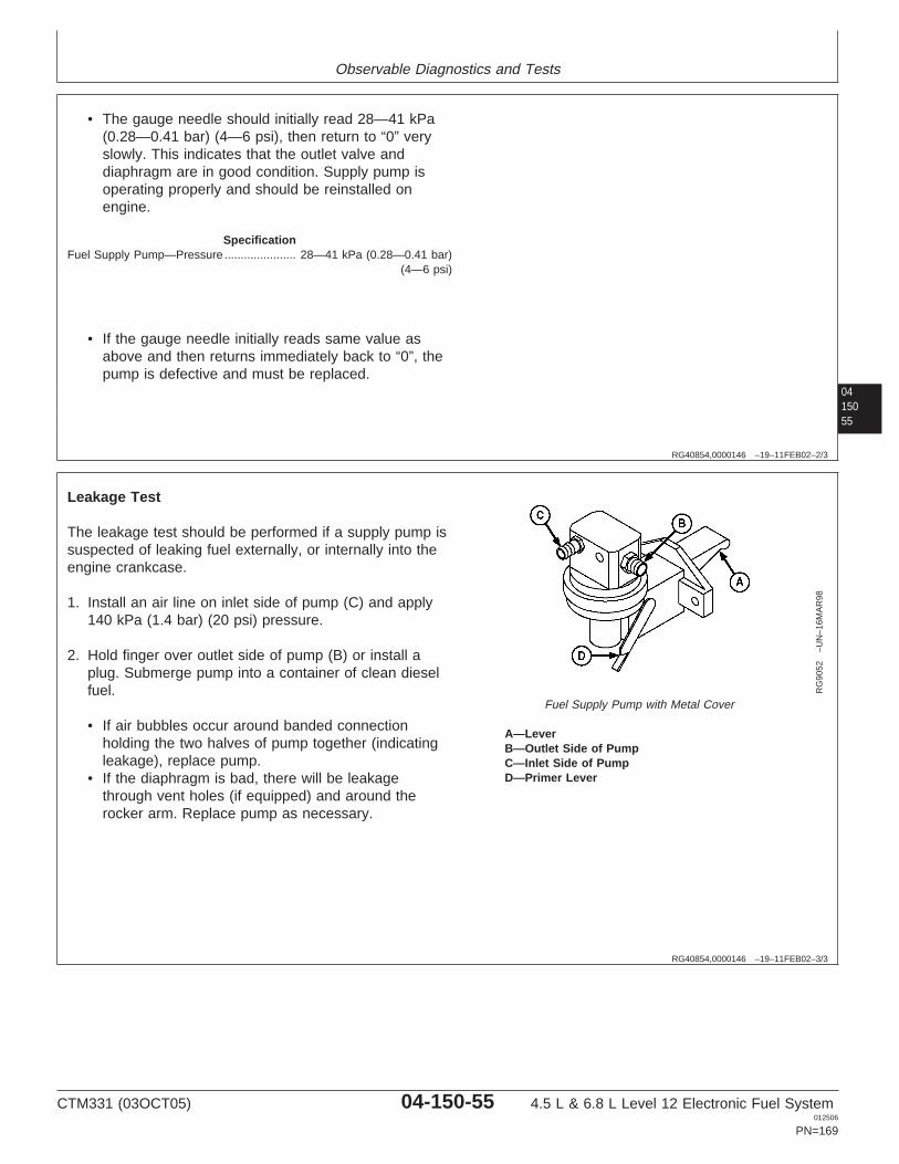
Observable Diagnostics and Tests
0415055
RG40854,0000146 –19–11FEB02–2/3
• The gauge needle should initially read 28—41 kPa(0.28—0.41 bar) (4—6 psi), then return to “0” veryslowly. This indicates that the outlet valve anddiaphragm are in good condition. Supply pump isoperating properly and should be reinstalled onengine.
SpecificationFuel Supply Pump—Pressure 28—41 kPa (0.28—0.41 bar)
(4—6 psi)......................
• If the gauge needle initially reads same value asabove and then returns immediately back to “0”, thepump is defective and must be replaced.
RG40854,0000146 –19–11FEB02–3/3
RG
9052
–UN
–16M
AR
98
Fuel Supply Pump with Metal Cover
A—LeverB—Outlet Side of PumpC—Inlet Side of PumpD—Primer Lever
Leakage Test
The leakage test should be performed if a supply pump issuspected of leaking fuel externally, or internally into theengine crankcase.
1. Install an air line on inlet side of pump (C) and apply140 kPa (1.4 bar) (20 psi) pressure.
2. Hold finger over outlet side of pump (B) or install aplug. Submerge pump into a container of clean dieselfuel.
• If air bubbles occur around banded connectionholding the two halves of pump together (indicatingleakage), replace pump.
• If the diaphragm is bad, there will be leakagethrough vent holes (if equipped) and around therocker arm. Replace pump as necessary.
CTM331 (03OCT05) 04-150-55 4.5 L & 6.8 L Level 12 Electronic Fuel System012506
PN=169
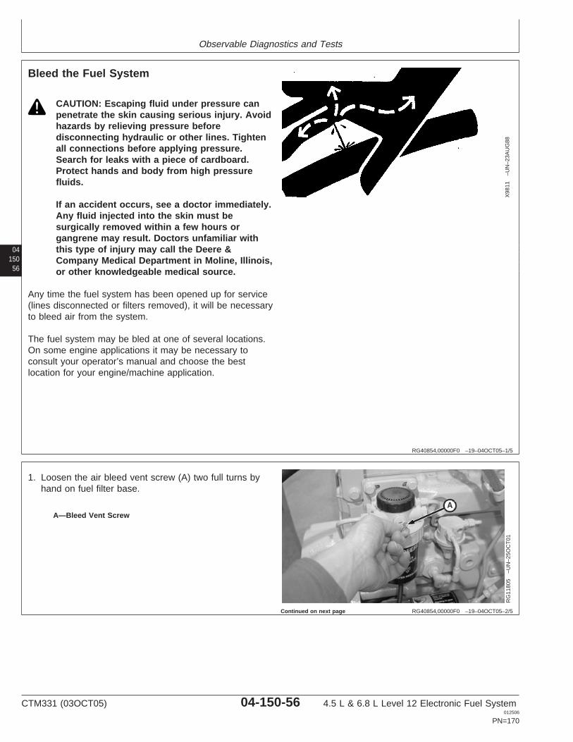
Observable Diagnostics and Tests
04150
56
RG40854,00000F0 –19–04OCT05–1/5
Bleed the Fuel System
X98
11–U
N–2
3AU
G88
CAUTION: Escaping fluid under pressure canpenetrate the skin causing serious injury. Avoidhazards by relieving pressure beforedisconnecting hydraulic or other lines. Tightenall connections before applying pressure.Search for leaks with a piece of cardboard.Protect hands and body from high pressurefluids.
If an accident occurs, see a doctor immediately.Any fluid injected into the skin must besurgically removed within a few hours organgrene may result. Doctors unfamiliar withthis type of injury may call the Deere &Company Medical Department in Moline, Illinois,or other knowledgeable medical source.
Any time the fuel system has been opened up for service(lines disconnected or filters removed), it will be necessaryto bleed air from the system.
The fuel system may be bled at one of several locations.On some engine applications it may be necessary toconsult your operator’s manual and choose the bestlocation for your engine/machine application.
RG40854,00000F0 –19–04OCT05–2/5
RG
1180
5–U
N–2
5OC
T01
A—Bleed Vent Screw
1. Loosen the air bleed vent screw (A) two full turns byhand on fuel filter base.
Continued on next page
CTM331 (03OCT05) 04-150-56 4.5 L & 6.8 L Level 12 Electronic Fuel System012506
PN=170
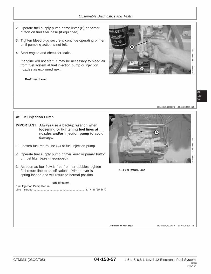
Observable Diagnostics and Tests
0415057
RG40854,00000F0 –19–04OCT05–3/5
RG
1180
6–U
N–2
5OC
T01
B—Primer Lever
2. Operate fuel supply pump prime lever (B) or primerbutton on fuel filter base (if equipped).
3. Tighten bleed plug securely; continue operating primeruntil pumping action is not felt.
4. Start engine and check for leaks.
If engine will not start, it may be necessary to bleed airfrom fuel system at fuel injection pump or injectionnozzles as explained next.
RG40854,00000F0 –19–04OCT05–4/5
RG
1180
7–U
N–2
5OC
T01
A—Fuel Return Line
At Fuel Injection Pump
IMPORTANT: Always use a backup wrench whenloosening or tightening fuel lines atnozzles and/or injection pump to avoiddamage.
1. Loosen fuel return line (A) at fuel injection pump.
2. Operate fuel supply pump primer lever or primer buttonon fuel filter base (if equipped).
3. As soon as fuel flow is free from air bubbles, tightenfuel return line to specifications. Primer lever isspring-loaded and will return to normal position.
SpecificationFuel Injection Pump ReturnLine—Torque 27 N•m (20 lb-ft)...................................................................
Continued on next page
CTM331 (03OCT05) 04-150-57 4.5 L & 6.8 L Level 12 Electronic Fuel System012506
PN=171
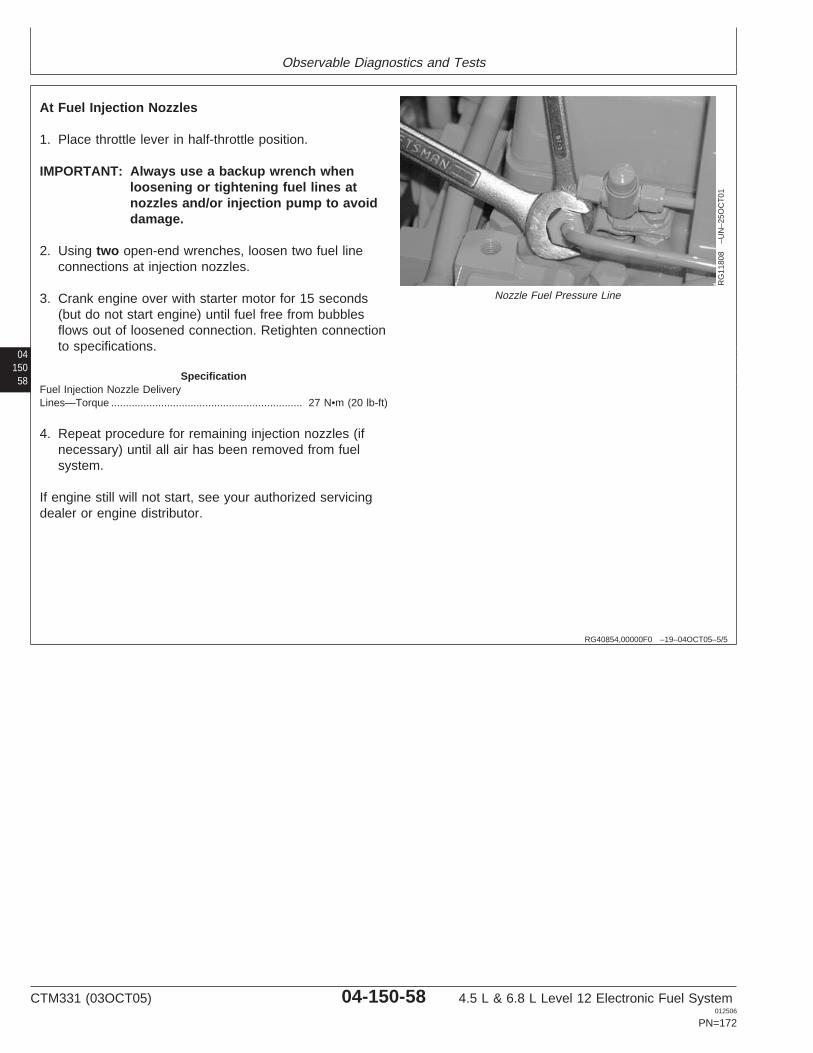
Observable Diagnostics and Tests
04150
58
RG40854,00000F0 –19–04OCT05–5/5
RG
1180
8–U
N–2
5OC
T01
Nozzle Fuel Pressure Line
At Fuel Injection Nozzles
1. Place throttle lever in half-throttle position.
IMPORTANT: Always use a backup wrench whenloosening or tightening fuel lines atnozzles and/or injection pump to avoiddamage.
2. Using two open-end wrenches, loosen two fuel lineconnections at injection nozzles.
3. Crank engine over with starter motor for 15 seconds(but do not start engine) until fuel free from bubblesflows out of loosened connection. Retighten connectionto specifications.
SpecificationFuel Injection Nozzle DeliveryLines—Torque 27 N•m (20 lb-ft).................................................................
4. Repeat procedure for remaining injection nozzles (ifnecessary) until all air has been removed from fuelsystem.
If engine still will not start, see your authorized servicingdealer or engine distributor.
CTM331 (03OCT05) 04-150-58 4.5 L & 6.8 L Level 12 Electronic Fuel System012506
PN=172
Observable Diagnostics and Tests
0415059
RG40854,00000F1 –19–04JAN02–1/1
Test for Cylinder Misfire (Engine Running)
CAUTION: Escaping fluid under pressure canpenetrate the skin causing serious injury. Keephands and body away from pinholes andnozzles which could inject fluids under highpressure.
If ANY fluid is injected into the skin, it must besurgically removed within a few hours by adoctor familiar with this type of injury organgrene may result. Doctors unfamiliar withthis type of injury may call the Deere &Company Medical Department in Moline, Illinois,or other knowledgeable medical source.
1. Operate engine at intermediate speed with no load.
2. Place a shop towel around nozzle-to-line connection toabsorb escaping fuel.
3. Slowly loosen the fuel pressure line at one of thenozzles until fuel escapes at the connection (fuel notopening nozzle valve).
• If engine speed changes, the cylinder is probablyworking satisfactory.
• If engine speed does not change, a cylinder is faulty.
4. Tighten fuel lines to specifications.
SpecificationFuel Injection Nozzle DeliveryLines—Torque 27 N•m (20 lb-ft).................................................................
5. Repeat test for each remaining cylinder.
6. Remove faulty injection nozzles and repair as required.See F5 - FUEL INJECTION NOZZLE CHECK earlier inthis Group.
CTM331 (03OCT05) 04-150-59 4.5 L & 6.8 L Level 12 Electronic Fuel System012506
PN=173
Observable Diagnostics and Tests
04150
60
CTM331 (03OCT05) 04-150-60 4.5 L & 6.8 L Level 12 Electronic Fuel System012506
PN=174
Group 160Trouble Code Diagnostics and Tests
041601
RG40854,00000FA –19–15JAN02–1/1
About this Group of the Manual
This section of the manual contains necessaryinformation to diagnose the electronic control system.Use this information in conjunction with the 4.5 L & 6.8L Diesel Engines Base Engine Manual (CTM104).
See the 4.5 L & 6.8 L Diesel Engines Base EngineManual (CTM 104) for:
• Removal of base engine components• Base engine repair procedures• Base engine disassembly• Base engine inspection• Base engine assembly
Parts such as sensors, actuators, connectors, andwiring harnesses are serviceable and available.
To help diagnose electronic control system problems,Section 06, Group 210 DIAGNOSTIC
SPECIFICATIONS contains useful information, such asECU terminal identification and a system wiringschematic.
IMPORTANT: Under NO circumstances, should theEngine Control Unit (ECU) beopened.
NOTE: Instruction is given throughout the diagnosticcharts to make resistance and voltagemeasurements in the ECU connector. Notethat these measurements are always made inthe harness end of the connector.Measurements should never be made in theECU end of the connection.
RG40854,00000FB –19–15JAN02–1/1
Electrical Concepts
Tests will include making measurements of voltage andresistance and making checks for open circuits and shortcircuits. An understanding of the following concepts isrequired to use the diagnostic procedures:
• Voltage (volts)• Current (amps)• Resistance (ohms)• Open Circuit• Short Circuit
CTM331 (03OCT05) 04-160-1 4.5 L & 6.8 L Level 12 Electronic Fuel System012506
PN=175
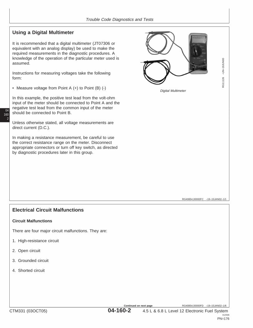
Trouble Code Diagnostics and Tests
04160
2
RG40854,00000FC –19–15JAN02–1/1
Using a Digital Multimeter
RG
1112
6–U
N–1
9JU
N00
Digital Multimeter
It is recommended that a digital multimeter (JT07306 orequivalent with an analog display) be used to make therequired measurements in the diagnostic procedures. Aknowledge of the operation of the particular meter used isassumed.
Instructions for measuring voltages take the followingform:
• Measure voltage from Point A (+) to Point (B) (-)
In this example, the positive test lead from the volt-ohminput of the meter should be connected to Point A and thenegative test lead from the common input of the metershould be connected to Point B.
Unless otherwise stated, all voltage measurements aredirect current (D.C.).
In making a resistance measurement, be careful to usethe correct resistance range on the meter. Disconnectappropriate connectors or turn off key switch, as directedby diagnostic procedures later in this group.
RG40854,00000FD –19–15JAN02–1/6
Electrical Circuit Malfunctions
Circuit Malfunctions
There are four major circuit malfunctions. They are:
1. High-resistance circuit
2. Open circuit
3. Grounded circuit
4. Shorted circuit
CTM331 (03OCT05) 04-160-2 4.5 L & 6.8 L Level 12 Electronic Fuel System012506
PN=176
Continued on next page
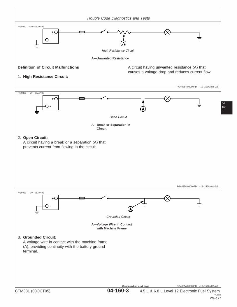
Trouble Code Diagnostics and Tests
RG40854,00000FD –19–15JAN02–2/6
RG9891 –UN–06JAN99
High Resistance Circuit
A—Unwanted Resistance
Definition of Circuit Malfunctions
1. High Resistance Circuit:
A circuit having unwanted resistance (A) thatcauses a voltage drop and reduces current flow.
041603
RG40854,00000FD –19–15JAN02–3/6
RG9892 –UN–06JAN99
Open Circuit
A—Break or Separation inCircuit
2. Open Circuit:A circuit having a break or a separation (A) thatprevents current from flowing in the circuit.
RG40854,00000FD –19–15JAN02–4/6
RG9893 –UN–06JAN99
Grounded Circuit
A—Voltage Wire in Contactwith Machine Frame
3. Grounded Circuit:A voltage wire in contact with the machine frame(A), providing continuity with the battery groundterminal.
CTM331 (03OCT05) 04-160-3 4.5 L & 6.8 L Level 12 Electronic Fuel System012506
PN=177
Continued on next page
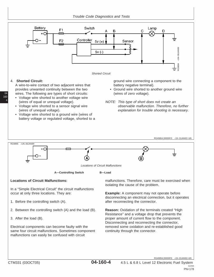
Trouble Code Diagnostics and Tests
04160
4
RG40854,00000FD –19–15JAN02–5/6
RG
9894
–UN
–06J
AN
99
Shorted Circuit
4. Shorted Circuit:A wire-to-wire contact of two adjacent wires thatprovides unwanted continuity between the twowires. The following are types of short circuits:• Voltage wire shorted to another voltage wire
(wires of equal or unequal voltage).• Voltage wire shorted to a sensor signal wire
(wires of unequal voltage).• Voltage wire shorted to a ground wire (wires of
battery voltage or regulated voltage, shorted to a
ground wire connecting a component to thebattery negative terminal).
• Ground wire shorted to another ground wire(wires of zero voltage).
NOTE: This type of short does not create anobservable malfunction. Therefore, no furtherexplanation for trouble shooting is necessary.
RG40854,00000FD –19–15JAN02–6/6
RG9895 –UN–06JAN99
Locations of Circuit Malfunctions
A—Controlling Switch B—Load
Locations of Circuit Malfunctions:
In a “Simple Electrical Circuit” the circuit malfunctionsoccur at only three locations. They are:
1. Before the controlling switch (A).
2. Between the controlling switch (A) and the load (B).
3. After the load (B).
Electrical components can become faulty with thesame four circuit malfunctions. Sometimes componentmalfunctions can easily be confused with circuit
malfunctions. Therefore, care must be exercised whenisolating the cause of the problem.
Example: A component may not operate beforedisconnecting an electrical connection, but it operatesafter reconnecting the connector.
Reason: Oxidation of the terminals created “HighResistance” and a voltage drop that prevents theproper amount of current flow to the component.Disconnecting and reconnecting the connector,removed some oxidation and re-established goodcontinuity through the connector.
CTM331 (03OCT05) 04-160-4 4.5 L & 6.8 L Level 12 Electronic Fuel System012506
PN=178
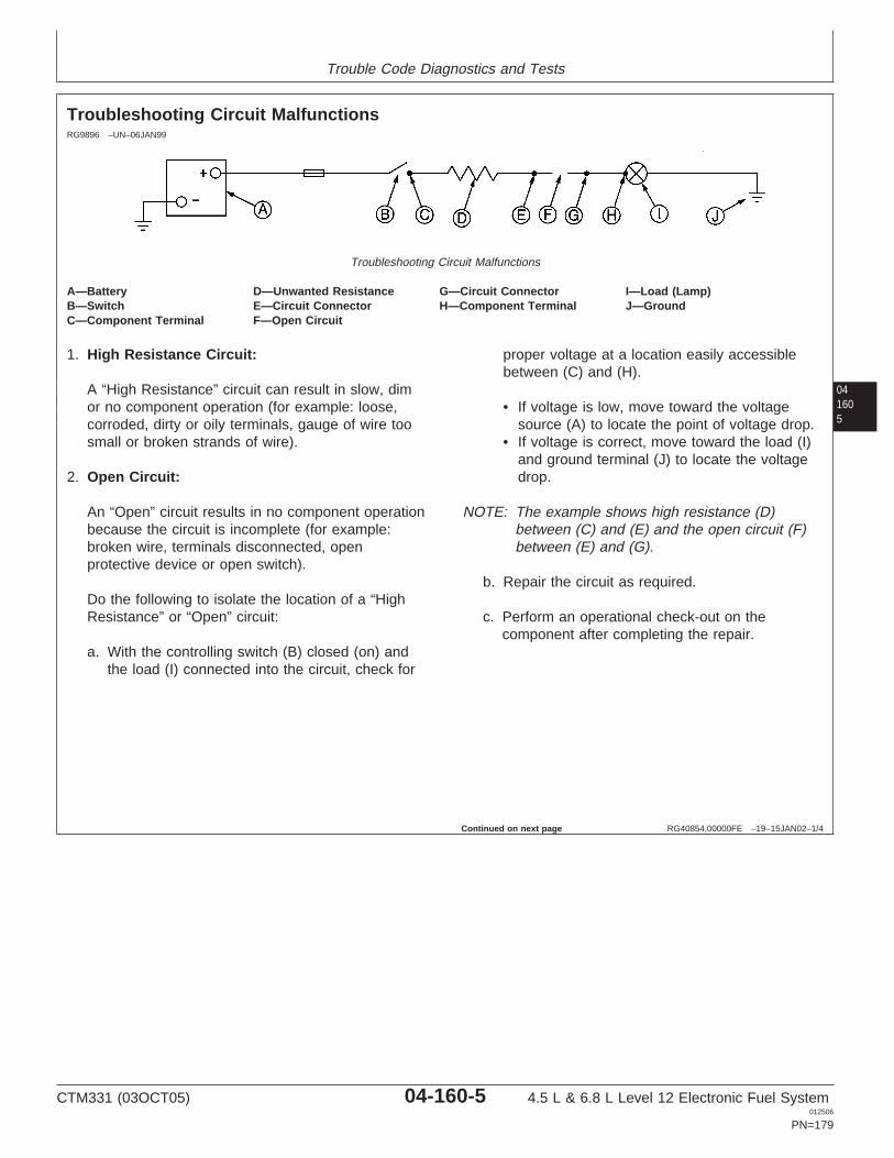
Trouble Code Diagnostics and Tests
041605
RG40854,00000FE –19–15JAN02–1/4
Troubleshooting Circuit MalfunctionsRG9896 –UN–06JAN99
Troubleshooting Circuit Malfunctions
A—Battery D—Unwanted Resistance G—Circuit Connector I—Load (Lamp)B—Switch E—Circuit Connector H—Component Terminal J—GroundC—Component Terminal F—Open Circuit
1. High Resistance Circuit:
A “High Resistance” circuit can result in slow, dimor no component operation (for example: loose,corroded, dirty or oily terminals, gauge of wire toosmall or broken strands of wire).
2. Open Circuit:
An “Open” circuit results in no component operationbecause the circuit is incomplete (for example:broken wire, terminals disconnected, openprotective device or open switch).
Do the following to isolate the location of a “HighResistance” or “Open” circuit:
a. With the controlling switch (B) closed (on) andthe load (I) connected into the circuit, check for
proper voltage at a location easily accessiblebetween (C) and (H).
• If voltage is low, move toward the voltagesource (A) to locate the point of voltage drop.
• If voltage is correct, move toward the load (I)and ground terminal (J) to locate the voltagedrop.
NOTE: The example shows high resistance (D)between (C) and (E) and the open circuit (F)between (E) and (G).
b. Repair the circuit as required.
c. Perform an operational check-out on thecomponent after completing the repair.
Continued on next page
CTM331 (03OCT05) 04-160-5 4.5 L & 6.8 L Level 12 Electronic Fuel System012506
PN=179
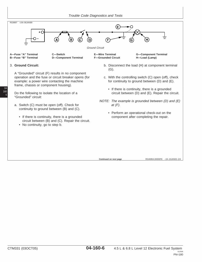
Trouble Code Diagnostics and Tests
04160
6
RG40854,00000FE –19–15JAN02–2/4
RG9897 –UN–06JAN99
Ground Circuit
A—Fuse “A” Terminal C—Switch E—Wire Terminal G—Component TerminalB—Fuse “B” Terminal D—Component Terminal F—Grounded Circuit H—Load (Lamp)
3. Ground Circuit:
A “Grounded” circuit (F) results in no componentoperation and the fuse or circuit breaker opens (forexample: a power wire contacting the machineframe, chassis or component housing).
Do the following to isolate the location of a“Grounded” circuit:
a. Switch (C) must be open (off). Check forcontinuity to ground between (B) and (C).
• If there is continuity, there is a groundedcircuit between (B) and (C). Repair the circuit.
• No continuity, go to step b.
b. Disconnect the load (H) at component terminal(G).
c. With the controlling switch (C) open (off), checkfor continuity to ground between (D) and (E).
• If there is continuity, there is a groundedcircuit between (D) and (E). Repair the circuit.
NOTE: The example is grounded between (D) and (E)at (F).
• Perform an operational check-out on thecomponent after completing the repair.
Continued on next page
CTM331 (03OCT05) 04-160-6 4.5 L & 6.8 L Level 12 Electronic Fuel System012506
PN=180

Trouble Code Diagnostics and Tests
041607
RG40854,00000FE –19–15JAN02–3/4
RG
9898
–UN
–06J
AN
99
Shorted Circuit
4. Shorted Circuit:
Machines equipped with several electronic controldevices contain wiring harnesses that can becomeshorted by one of the following ways shown above.
1. Battery wire from fuse (F1) is shorted at (A) toanother battery wire after switch (Sw.2).• Result: Lamp (E1) is on all of the time.
2. Battery wire from fuse (F1) is shorted at (B) toanother battery wire after switches (Sw.1 & 2).• Result: Both lamps (E1 & E2) operate on
either switch (Sw. 1 or 2).
3. Battery wire from fuse (F1) is shorted at (C) to aground wire.• Result: Fuse (F1) opens after closing switch
(Sw. 1)
4. Battery wire from switch (Sw. 2) is shorted at (D)to a regulated voltage wire.• Result: The sensor signal voltage is distorted.1
5. Battery wire from switch (Sw. 2) is shorted at (E)to the sensor signal voltage wire.• Result: The sensor signal is distorted.1
6. Battery wire from switch (Sw. 2) is shorted at (F)to the sensor ground wire.
• Result: Fuse (F2) opens after closing switch(Sw. 2) and the sensor signal is distorted.1
7. Controller regulated voltage wire is shorted at(G) to the sensor signal voltage wire.• Result: The sensor signal is distorted.
8. Controller regulated voltage wire is shorted at(H) to the sensor ground wire.• Result: The sensor signal is distorted.1
9. Sensor voltage wire is shorted at (I) to thesensor ground wire.• Result: The sensor signal is distorted.1
Do the following to isolate a “Shorted Circuit:”
a. Review the machine electrical schematic toidentify the circuits for the component that doesnot operate.
b. Disconnect the components at each end of thecircuits, to single out the affected wires.
c. To prevent damage to connector terminals,obtain mating connector terminals from repairparts. DO NOT force meter probes intoconnector terminals.
1The sensor signal voltage goes out of range and a fault code maybe restored. The controller may shut down or provide limitedoperation for its function.
CTM331 (03OCT05) 04-160-7 4.5 L & 6.8 L Level 12 Electronic Fuel System012506
PN=181
Continued on next page
Trouble Code Diagnostics and Tests
04160
8
RG40854,00000FE –19–15JAN02–4/4
d. Connect the meter leads across two of the affectedcircuits. The meter should show no continuitybetween the two circuits. Repeat the check acrossanother combination of two circuits until all affectedcircuits have been checked.
e. Then, connect a meter lead to each affected circuitone at a time and touch the other meter leads to allterminals in the connector. The meter should showno continuity between any two circuits.
Example: A 37 pin connector contains three wiresto a sensor. With one meter probe attached to eachof the three wires, one at a time, touch the othermeter probe to the remaining 36 wires. If there iscontinuity between any two wires, the circuit isshorted. Repair the circuit.
f. Alternate Method to Check for Shorted Circuit.
With the components disconnected at each end ofthe suspected circuits, turn the key switch on.
Connect one meter lead to a good frame ground.With the other meter probe, touch each of thesuspected circuits one at a time. If there is a voltagereading, the circuit is shorted to another voltagewire. Repair the circuit.
g. Repair the “Shorted Circuit” as follows:
• Wires not in a loom: Wrap individual wires withelectrical tape or replace the damaged wire andband as required.
• Wires in a loom: If hot spots exist in shorted areaof the harness, replace the harness. If hot sportsare not noticeable, install a new wire of propergauge between the last two connections. Use tiebands to secure the wire to outside of theharness.
h. Perform an operational check-out on the componentafter completing the repair.
CTM331 (03OCT05) 04-160-8 4.5 L & 6.8 L Level 12 Electronic Fuel System012506
PN=182

Trouble Code Diagnostics and Tests
041609
CTM331 (03OCT05) 04-160-9 4.5 L & 6.8 L Level 12 Electronic Fuel System012506
PN=183
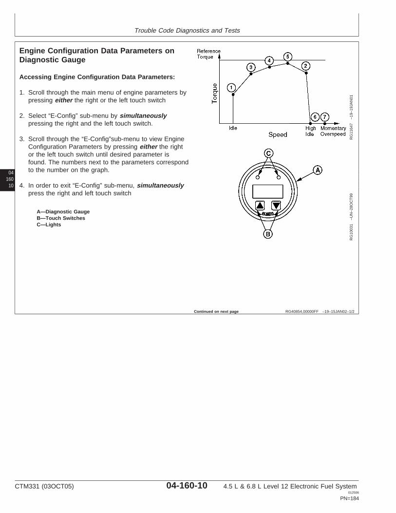
Trouble Code Diagnostics and Tests
04160
10
RG40854,00000FF –19–15JAN02–1/2
Engine Configuration Data Parameters onDiagnostic Gauge
RG
1164
7–1
9–19
JAN
01R
G10
031
–UN
–28O
CT
99
A—Diagnostic GaugeB—Touch SwitchesC—Lights
Accessing Engine Configuration Data Parameters:
1. Scroll through the main menu of engine parameters bypressing either the right or the left touch switch
2. Select “E-Config” sub-menu by simultaneouslypressing the right and the left touch switch.
3. Scroll through the “E-Config”sub-menu to view EngineConfiguration Parameters by pressing either the rightor the left touch switch until desired parameter isfound. The numbers next to the parameters correspondto the number on the graph.
4. In order to exit “E-Config” sub-menu, simultaneouslypress the right and left touch switch
Continued on next page
CTM331 (03OCT05) 04-160-10 4.5 L & 6.8 L Level 12 Electronic Fuel System012506
PN=184
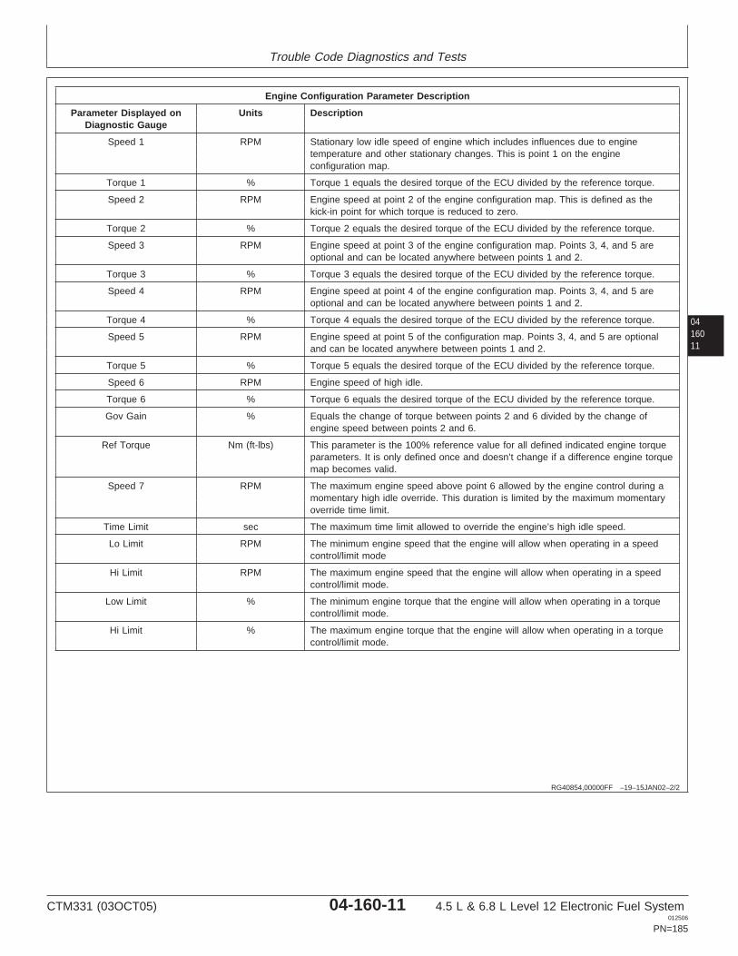
Trouble Code Diagnostics and Tests
0416011
RG40854,00000FF –19–15JAN02–2/2
Engine Configuration Parameter Description
Parameter Displayed on Units DescriptionDiagnostic Gauge
Speed 1 RPM Stationary low idle speed of engine which includes influences due to enginetemperature and other stationary changes. This is point 1 on the engineconfiguration map.
Torque 1 % Torque 1 equals the desired torque of the ECU divided by the reference torque.
Speed 2 RPM Engine speed at point 2 of the engine configuration map. This is defined as thekick-in point for which torque is reduced to zero.
Torque 2 % Torque 2 equals the desired torque of the ECU divided by the reference torque.
Speed 3 RPM Engine speed at point 3 of the engine configuration map. Points 3, 4, and 5 areoptional and can be located anywhere between points 1 and 2.
Torque 3 % Torque 3 equals the desired torque of the ECU divided by the reference torque.
Speed 4 RPM Engine speed at point 4 of the engine configuration map. Points 3, 4, and 5 areoptional and can be located anywhere between points 1 and 2.
Torque 4 % Torque 4 equals the desired torque of the ECU divided by the reference torque.
Speed 5 RPM Engine speed at point 5 of the configuration map. Points 3, 4, and 5 are optionaland can be located anywhere between points 1 and 2.
Torque 5 % Torque 5 equals the desired torque of the ECU divided by the reference torque.
Speed 6 RPM Engine speed of high idle.
Torque 6 % Torque 6 equals the desired torque of the ECU divided by the reference torque.
Gov Gain % Equals the change of torque between points 2 and 6 divided by the change ofengine speed between points 2 and 6.
Ref Torque Nm (ft-lbs) This parameter is the 100% reference value for all defined indicated engine torqueparameters. It is only defined once and doesn’t change if a difference engine torquemap becomes valid.
Speed 7 RPM The maximum engine speed above point 6 allowed by the engine control during amomentary high idle override. This duration is limited by the maximum momentaryoverride time limit.
Time Limit sec The maximum time limit allowed to override the engine’s high idle speed.
Lo Limit RPM The minimum engine speed that the engine will allow when operating in a speedcontrol/limit mode
Hi Limit RPM The maximum engine speed that the engine will allow when operating in a speedcontrol/limit mode.
Low Limit % The minimum engine torque that the engine will allow when operating in a torquecontrol/limit mode.
Hi Limit % The maximum engine torque that the engine will allow when operating in a torquecontrol/limit mode.
CTM331 (03OCT05) 04-160-11 4.5 L & 6.8 L Level 12 Electronic Fuel System012506
PN=185
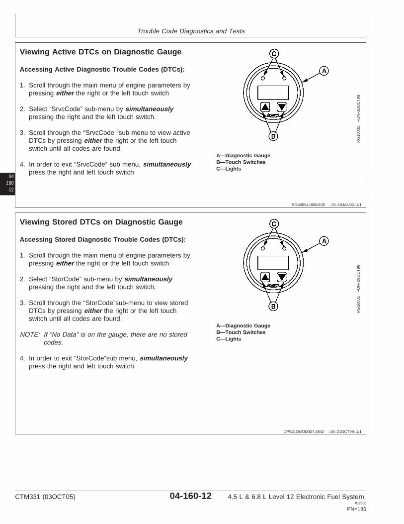
Trouble Code Diagnostics and Tests
04160
12
RG40854,0000100 –19–15JAN02–1/1
Viewing Active DTCs on Diagnostic Gauge
RG
1003
1–U
N–2
8OC
T99
A—Diagnostic GaugeB—Touch SwitchesC—Lights
Accessing Active Diagnostic Trouble Codes (DTCs):
1. Scroll through the main menu of engine parameters bypressing either the right or the left touch switch
2. Select “SrvcCode” sub-menu by simultaneouslypressing the right and the left touch switch.
3. Scroll through the “SrvcCode ”sub-menu to view activeDTCs by pressing either the right or the left touchswitch until all codes are found.
4. In order to exit “SrvcCode” sub menu, simultaneouslypress the right and left touch switch
DPSG,OUOD007,2842 –19–21OCT99–1/1
Viewing Stored DTCs on Diagnostic Gauge
RG
1003
1–U
N–2
8OC
T99
A—Diagnostic GaugeB—Touch SwitchesC—Lights
Accessing Stored Diagnostic Trouble Codes (DTCs):
1. Scroll through the main menu of engine parameters bypressing either the right or the left touch switch
2. Select “StorCode” sub-menu by simultaneouslypressing the right and the left touch switch.
3. Scroll through the “StorCode”sub-menu to view storedDTCs by pressing either the right or the left touchswitch until all codes are found.
NOTE: If “No Data” is on the gauge, there are no storedcodes.
4. In order to exit “StorCode”sub menu, simultaneouslypress the right and left touch switch
CTM331 (03OCT05) 04-160-12 4.5 L & 6.8 L Level 12 Electronic Fuel System012506
PN=186
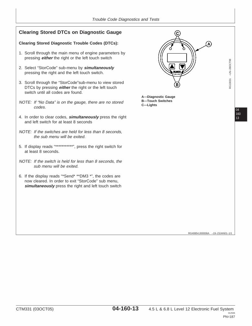
Trouble Code Diagnostics and Tests
0416013
RG40854,000006A –19–23JAN01–1/1
Clearing Stored DTCs on Diagnostic Gauge
RG
1003
1–U
N–2
8OC
T99
A—Diagnostic GaugeB—Touch SwitchesC—Lights
Clearing Stored Diagnostic Trouble Codes (DTCs):
1. Scroll through the main menu of engine parameters bypressing either the right or the left touch switch
2. Select “StorCode” sub-menu by simultaneouslypressing the right and the left touch switch.
3. Scroll through the “StorCode”sub-menu to view storedDTCs by pressing either the right or the left touchswitch until all codes are found.
NOTE: If “No Data” is on the gauge, there are no storedcodes.
4. In order to clear codes, simultaneously press the rightand left switch for at least 8 seconds
NOTE: If the switches are held for less than 8 seconds,the sub menu will be exited.
5. If display reads “***********”, press the right switch forat least 8 seconds.
NOTE: If the switch is held for less than 8 seconds, thesub menu will be exited.
6. If the display reads “*Send* **DM3 *”, the codes arenow cleared. In order to exit “StorCode” sub menu,simultaneously press the right and left touch switch
CTM331 (03OCT05) 04-160-13 4.5 L & 6.8 L Level 12 Electronic Fuel System012506
PN=187
Trouble Code Diagnostics and Tests
04160
14
RG40854,0000102 –19–15JAN02–1/1
Blinking DTCs
On OEM applications that have a Fault Lamp, the ECUhas the ability to display DTCs using blinkingsequence of the fault lamp. To retrieve DTCs from theECU using the “blink code” method:
NOTE: The ECU blinks the codes in 2-digit codesonly. In order to convert the codes to SPN/FMIcodes, see LISTING OF DIAGNOSTICTROUBLE CODES (DTCS) ON ECU later inthis Group.
1. Turn the ignition switch “ON”.
2. Hold Override Shutdown Switch for a few seconds
3. The Fault Lamp will begin to flash a code number.For example, flash three times...short pause...flashtwo times...long pause. This example is code 32.
4. The ECU begins the flashing sequence by flashinga code 32, this indicates the start of blinking activecodes. If there are any active DTCs, the ECU willflash it’s 2–digit number. If there is more than oneactive DTC, the ECU will flash each code innumerical order. If there are no active DTCs, theFault Lamp will flash a code 88.
5. Following the active codes, the Fault Lamp willflash a code 33, this indicates the start of blinkingstored codes. If there are any stored DTCs, theFault Lamp will flash it’s 2–digit number. If there ismore than one stored DTC, the ECU will flash eachcode in numerical order. If there are no storedDTCs, the Fault Lamp will flash a code 88.
6. Once complete, the above sequence will berepeated.
7. When complete, turn ignition “OFF”
As an example, if an engine had an active DTC 18and stored DTC 53, the flashing sequence would be:
• flash three times...short pause• flash two times...long pause• flash one time...short pause• flash eight times...long pause• flash three times...short pause• flash three times...long pause• flash five times...short pause• flash three times
CTM331 (03OCT05) 04-160-14 4.5 L & 6.8 L Level 12 Electronic Fuel System012506
PN=188

Trouble Code Diagnostics and Tests
0416015
CTM331 (03OCT05) 04-160-15 4.5 L & 6.8 L Level 12 Electronic Fuel System012506
PN=189
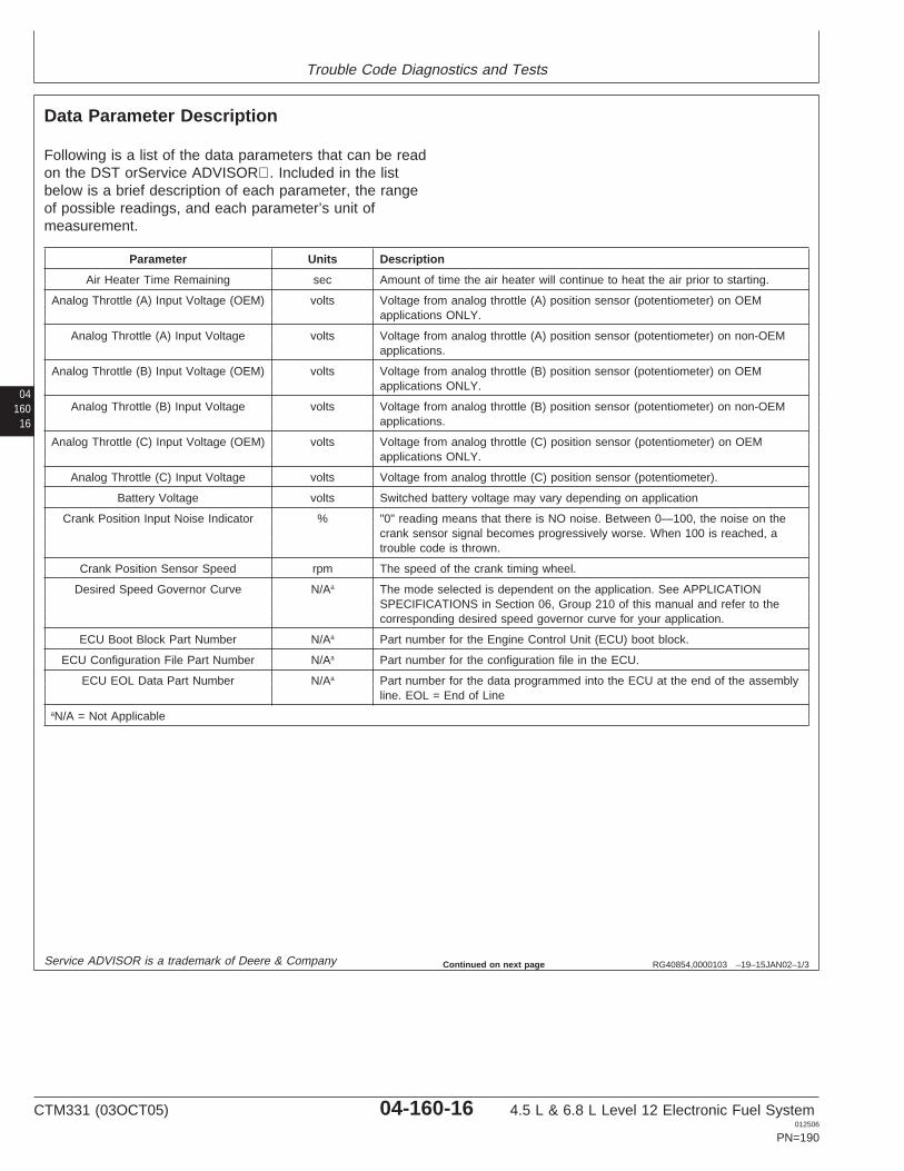
Trouble Code Diagnostics and Tests
04160
16
RG40854,0000103 –19–15JAN02–1/3
Data Parameter Description
Following is a list of the data parameters that can be readon the DST orService ADVISOR. Included in the listbelow is a brief description of each parameter, the rangeof possible readings, and each parameter’s unit ofmeasurement.
Parameter Units Description
Air Heater Time Remaining sec Amount of time the air heater will continue to heat the air prior to starting.
Analog Throttle (A) Input Voltage (OEM) volts Voltage from analog throttle (A) position sensor (potentiometer) on OEMapplications ONLY.
Analog Throttle (A) Input Voltage volts Voltage from analog throttle (A) position sensor (potentiometer) on non-OEMapplications.
Analog Throttle (B) Input Voltage (OEM) volts Voltage from analog throttle (B) position sensor (potentiometer) on OEMapplications ONLY.
Analog Throttle (B) Input Voltage volts Voltage from analog throttle (B) position sensor (potentiometer) on non-OEMapplications.
Analog Throttle (C) Input Voltage (OEM) volts Voltage from analog throttle (C) position sensor (potentiometer) on OEMapplications ONLY.
Analog Throttle (C) Input Voltage volts Voltage from analog throttle (C) position sensor (potentiometer).
Battery Voltage volts Switched battery voltage may vary depending on application
Crank Position Input Noise Indicator % "0" reading means that there is NO noise. Between 0—100, the noise on thecrank sensor signal becomes progressively worse. When 100 is reached, atrouble code is thrown.
Crank Position Sensor Speed rpm The speed of the crank timing wheel.
Desired Speed Governor Curve N/Aa The mode selected is dependent on the application. See APPLICATIONSPECIFICATIONS in Section 06, Group 210 of this manual and refer to thecorresponding desired speed governor curve for your application.
ECU Boot Block Part Number N/Aa Part number for the Engine Control Unit (ECU) boot block.
ECU Configuration File Part Number N/Aa Part number for the configuration file in the ECU.
ECU EOL Data Part Number N/Aa Part number for the data programmed into the ECU at the end of the assemblyline. EOL = End of Line
aN/A = Not Applicable
Service ADVISOR is a trademark of Deere & Company Continued on next page
CTM331 (03OCT05) 04-160-16 4.5 L & 6.8 L Level 12 Electronic Fuel System012506
PN=190
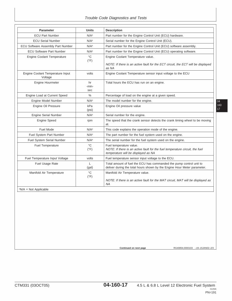
Trouble Code Diagnostics and Tests
0416017
RG40854,0000103 –19–15JAN02–2/3
Parameter Units Description
ECU Part Number N/Aa Part number for the Engine Control Unit (ECU) hardware.
ECU Serial Number N/Aa Serial number for the Engine Control Unit (ECU).
ECU Software Assembly Part Number N/Aa Part number for the Engine Control Unit (ECU) software assembly.
ECU Software Part Number N/Aa Part number for the Engine Control Unit (ECU) operating software.
Engine Coolant Temperature °C Engine Coolant Temperature value.(°F)
NOTE: If there is an active fault for the ECT circuit, the ECT will be displayedas NA
Engine Coolant Temperature Input volts Engine Coolant Temperature sensor input voltage to the ECUVoltage
Engine Hourmeter hr Total hours the ECU has run on an engine.-min-sec
Engine Load at Current Speed % Percentage of load on the engine at a given speed.
Engine Model Number N/Aa The model number for the engine.
Engine Oil Pressure kPa Engine Oil pressure value(psi)
Engine Serial Number N/Aa Serial number for the engine.
Engine Speed rpm The speed that the crank sensor detects the crank timing wheel to be movingat.
Fuel Mode N/Aa This code explains the operation mode of the engine.
Fuel System Part Number N/Aa The part number for the fuel system used on the engine.
Fuel System Serial Number N/Aa The serial number for the fuel system used on the engine.
Fuel Temperature °C Fuel temperature value.(°F) NOTE: If there is an active fault for the fuel temperature circuit, the fuel
temperature will be displayed as NA
Fuel Temperature Input Voltage volts Fuel temperature sensor input voltage to the ECU.
Fuel Usage Rate L Total amount of fuel the ECU has commanded the pump control unit to(gal) deliver during the total hours shown by the Engine Hour Meter parameter.
Manifold Air Temperature °C Manifold Air Temperature value.(°F)
NOTE: If there is an active fault for the MAT circuit, MAT will be displayed asNA
aN/A = Not Applicable
Continued on next page
CTM331 (03OCT05) 04-160-17 4.5 L & 6.8 L Level 12 Electronic Fuel System012506
PN=191
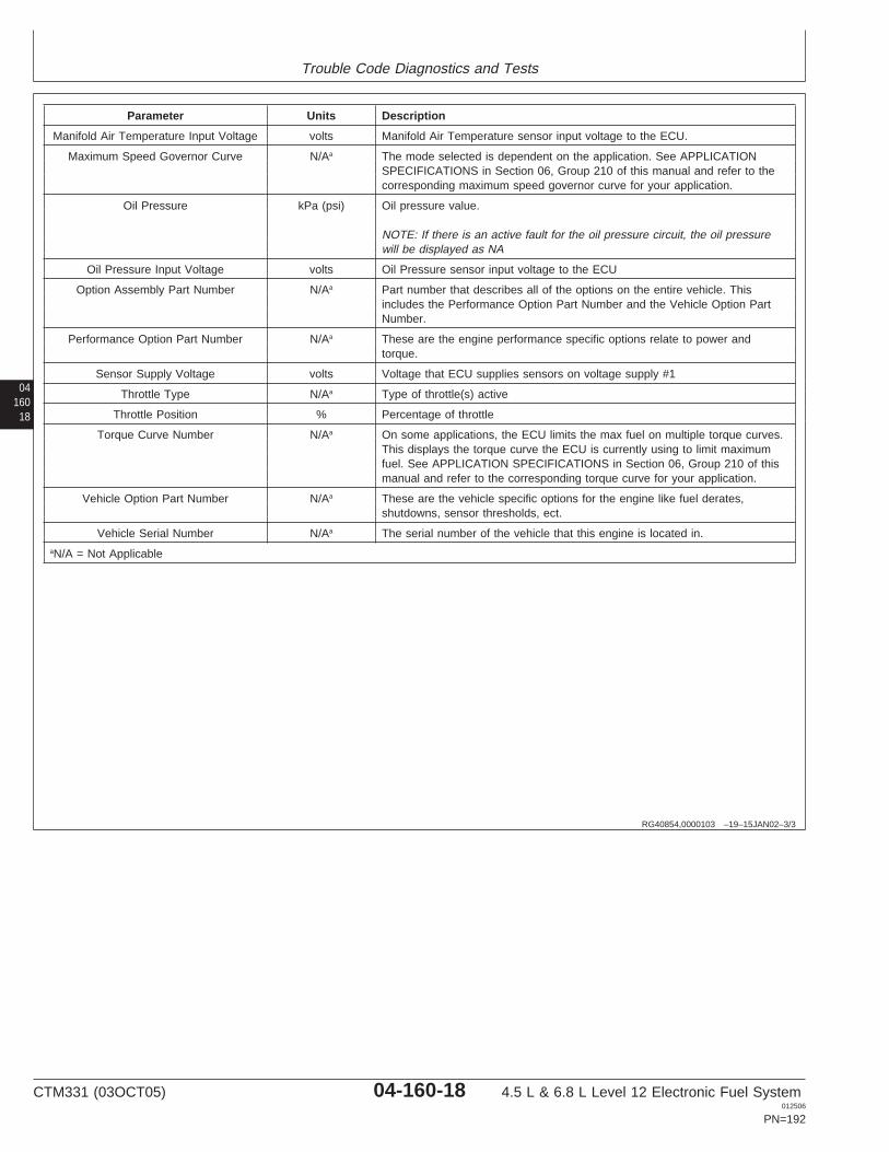
Trouble Code Diagnostics and Tests
04160
18
RG40854,0000103 –19–15JAN02–3/3
Parameter Units Description
Manifold Air Temperature Input Voltage volts Manifold Air Temperature sensor input voltage to the ECU.
Maximum Speed Governor Curve N/Aa The mode selected is dependent on the application. See APPLICATIONSPECIFICATIONS in Section 06, Group 210 of this manual and refer to thecorresponding maximum speed governor curve for your application.
Oil Pressure kPa (psi) Oil pressure value.
NOTE: If there is an active fault for the oil pressure circuit, the oil pressurewill be displayed as NA
Oil Pressure Input Voltage volts Oil Pressure sensor input voltage to the ECU
Option Assembly Part Number N/Aa Part number that describes all of the options on the entire vehicle. Thisincludes the Performance Option Part Number and the Vehicle Option PartNumber.
Performance Option Part Number N/Aa These are the engine performance specific options relate to power andtorque.
Sensor Supply Voltage volts Voltage that ECU supplies sensors on voltage supply #1
Throttle Type N/Aa Type of throttle(s) active
Throttle Position % Percentage of throttle
Torque Curve Number N/Aa On some applications, the ECU limits the max fuel on multiple torque curves.This displays the torque curve the ECU is currently using to limit maximumfuel. See APPLICATION SPECIFICATIONS in Section 06, Group 210 of thismanual and refer to the corresponding torque curve for your application.
Vehicle Option Part Number N/Aa These are the vehicle specific options for the engine like fuel derates,shutdowns, sensor thresholds, ect.
Vehicle Serial Number N/Aa The serial number of the vehicle that this engine is located in.aN/A = Not Applicable
CTM331 (03OCT05) 04-160-18 4.5 L & 6.8 L Level 12 Electronic Fuel System012506
PN=192
Trouble Code Diagnostics and Tests
0416019
RG40854,0000171 –19–23SEP05–1/1
Engine Test Instructions - Excavator TorqueCurve Change Test
Torque curve adjustment may be necessary forexcavators operating in high altitude areas. By selectingthe altitude derate option, undesired observable symptomssuch as excessive black smoke can be significantlyreduced or eliminated. Torque curve adjustment can onlybe accomplished with the DST orSERVICE ADVISOR.
Performing the Torque Curve High-altitudeAdjustment
1. Ignition ON, engine off.
2. Select Excavator Torque Curve Change Test on theDST orSERVICE ADVISOR.
3. Select the option that corresponds to the desiredoperation.
1. Normal operation2. Altitude derate
SERVICE ADVISOR is a trademark of Deere & Company
RG41221,0000092 –19–23SEP05–1/1
Reprogramming Engine Control Unit (ECU)
The ECU may be reprogrammed using the DSTorSERVICE ADVISOR. Refer to the training materialprovided with your Service Advisor training course. Allauthorized Service Advisor users have received thistraining. Also, online training is available at John DeereUniversity, which is an internet-based distance-learningapplication.
SERVICE ADVISOR is a trademark of Deere & Company
CTM331 (03OCT05) 04-160-19 4.5 L & 6.8 L Level 12 Electronic Fuel System012506
PN=193
Trouble Code Diagnostics and Tests
04160
20
RG40854,0000104 –19–07SEP05–1/1
Diagnostic Trouble Codes (DTCs)
There are several different methods of displaying bothstored and active DTCs from the ECU.
SPN/FMI CODES
SPN/FMI codes are written from the SAE J1939standard as a two part code. The first part is called theSuspect Parameter Number (SPN). Typically, itcontains between 2 and 4 digits. The SPN identifiesthe system or the component that has the failure; forexample SPN 110 indicates a failure in the enginecoolant temperature circuit. The second part of thecode is called the Failure Mode Identifier (FMI) code.The FMI contains 2 digits. The FMI identifies the typeof failure that has occurred; for example FMI 3indicates value above normal. In order to determinethe exact failure, both the SPN and FMI are required.Combining SPN 110 with FMI 3 yields engine coolanttemperature input voltage high.
On all applications with the Level 12 Engine ControlUnit (ECU), the ECU transmits SPN/FMI codes overthe Controller Area Network (CAN). This allows forservice tools such as the DST orSERVICE ADVISORand the Diagnostic Gauge to display active and storedDTCs. When using the DST orSERVICE ADVISORthe codes will be displayed in a 000000.00 format. Forexample, SPN 110 FMI 3 will be displayed as000110.03.
2-DIGIT CODES
Some applications do not display engine codes as anSPN/FMI. In most of these cases, the code isdisplayed as a 2-digit code. An example of a 2-digitcode is 18 for engine coolant temperature inputvoltage high. If used on an application with multiplecontrollers, ECU may be displayed in front of thenumbers, such as ECU 018. A 2-digit code may beseen on the DST orSERVICE ADVISOR, theon-board display, or when the code is blinked for
various reasons. In this manual, it will be necessary toconvert these codes to the SPN/FMI code in order tofollow the correct diagnostic procedure. See LISTINGOF DIAGNOSTIC TROUBLE CODES (DTCS) ONECU in Group 160 of this manual.
OTHER CODES
If codes are not displayed as SPN/FMI or as 2-digitcodes, there may be another format that theapplication is using. For example on someapplications, the code F455 is displayed for enginecoolant temperature input voltage high. This may beseen on some applications within the DST orSERVICEADVISOR. In this manual, it is necessary to convertthis format of code into an SPN/FMI code to ensurethat the correct diagnostic procedure is followed. SeeLISTING OF DIAGNOSTIC TROUBLE CODES(DTCS) ON ECU
WARNING LAMP
On some applications, there is a warning lamp that isused when a code becomes active. When a code isactive, this lamp will either blink or stay on solid.Typically, a solid light indicates that the ECU is takingextreme measures to protect the engine, and ablinking light indicates that the ECU has detected afault and engine performance may be affected. Referto Operator’s Manual for a given application for moredetailed information.
CLEARING STORED DTCS
Stored DTCs can be cleared through the OEMinstrument panel, through the DST orSERVICEADVISOR. For more information on clearing DTCsusing the diagnostic code reader on the instrumentpanel, see CLEARING STORED DTCS ONDIAGNOSTIC GAUGE earlier in this Group.
SERVICE ADVISOR is a trademark of Deere & CompanySERVICE ADVISOR
CTM331 (03OCT05) 04-160-20 4.5 L & 6.8 L Level 12 Electronic Fuel System012506
PN=194

Trouble Code Diagnostics and Tests
0416021
CTM331 (03OCT05) 04-160-21 4.5 L & 6.8 L Level 12 Electronic Fuel System012506
PN=195
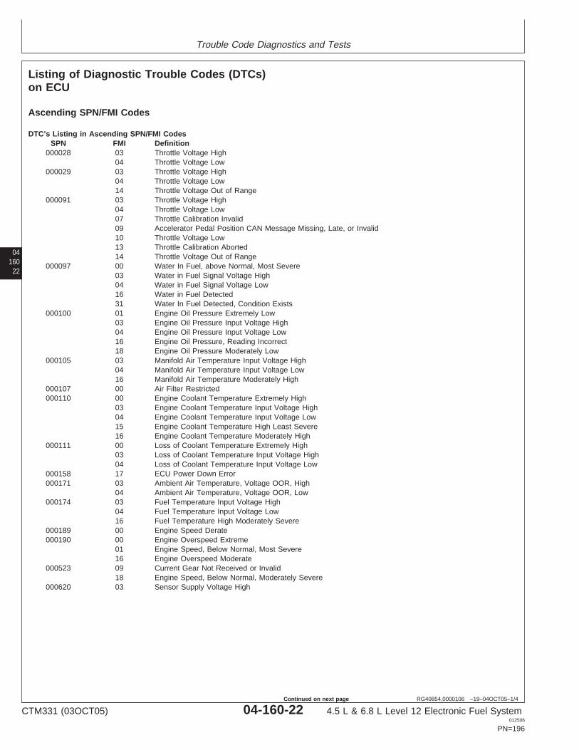
Trouble Code Diagnostics and Tests
04160
22
RG40854,0000106 –19–04OCT05–1/4
Listing of Diagnostic Trouble Codes (DTCs)on ECU
Ascending SPN/FMI Codes
DTC’s Listing in Ascending SPN/FMI CodesSPN FMI Definition
000028 03 Throttle Voltage High04 Throttle Voltage Low
000029 03 Throttle Voltage High04 Throttle Voltage Low14 Throttle Voltage Out of Range
000091 03 Throttle Voltage High04 Throttle Voltage Low07 Throttle Calibration Invalid09 Accelerator Pedal Position CAN Message Missing, Late, or Invalid10 Throttle Voltage Low13 Throttle Calibration Aborted14 Throttle Voltage Out of Range
000097 00 Water In Fuel, above Normal, Most Severe03 Water in Fuel Signal Voltage High04 Water in Fuel Signal Voltage Low16 Water in Fuel Detected31 Water In Fuel Detected, Condition Exists
000100 01 Engine Oil Pressure Extremely Low03 Engine Oil Pressure Input Voltage High04 Engine Oil Pressure Input Voltage Low16 Engine Oil Pressure, Reading Incorrect18 Engine Oil Pressure Moderately Low
000105 03 Manifold Air Temperature Input Voltage High04 Manifold Air Temperature Input Voltage Low16 Manifold Air Temperature Moderately High
000107 00 Air Filter Restricted000110 00 Engine Coolant Temperature Extremely High
03 Engine Coolant Temperature Input Voltage High04 Engine Coolant Temperature Input Voltage Low15 Engine Coolant Temperature High Least Severe16 Engine Coolant Temperature Moderately High
000111 00 Loss of Coolant Temperature Extremely High03 Loss of Coolant Temperature Input Voltage High04 Loss of Coolant Temperature Input Voltage Low
000158 17 ECU Power Down Error000171 03 Ambient Air Temperature, Voltage OOR, High
04 Ambient Air Temperature, Voltage OOR, Low000174 03 Fuel Temperature Input Voltage High
04 Fuel Temperature Input Voltage Low16 Fuel Temperature High Moderately Severe
000189 00 Engine Speed Derate000190 00 Engine Overspeed Extreme
01 Engine Speed, Below Normal, Most Severe16 Engine Overspeed Moderate
000523 09 Current Gear Not Received or Invalid18 Engine Speed, Below Normal, Moderately Severe
000620 03 Sensor Supply Voltage High
CTM331 (03OCT05) 04-160-22 4.5 L & 6.8 L Level 12 Electronic Fuel System012506
PN=196
Continued on next page
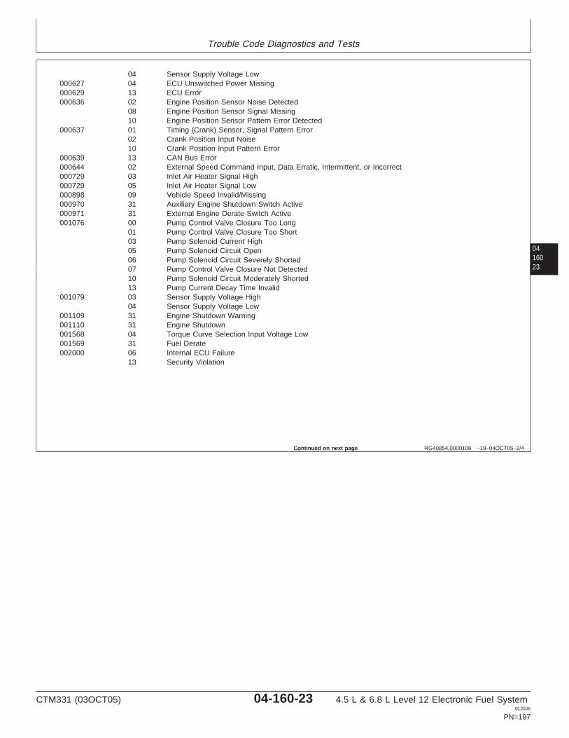
Trouble Code Diagnostics and Tests
0416023
RG40854,0000106 –19–04OCT05–2/4
04 Sensor Supply Voltage Low000627 04 ECU Unswitched Power Missing000629 13 ECU Error000636 02 Engine Position Sensor Noise Detected
08 Engine Position Sensor Signal Missing10 Engine Position Sensor Pattern Error Detected
000637 01 Timing (Crank) Sensor, Signal Pattern Error02 Crank Position Input Noise10 Crank Position Input Pattern Error
000639 13 CAN Bus Error000644 02 External Speed Command Input, Data Erratic, Intermittent, or Incorrect000729 03 Inlet Air Heater Signal High000729 05 Inlet Air Heater Signal Low000898 09 Vehicle Speed Invalid/Missing000970 31 Auxiliary Engine Shutdown Switch Active000971 31 External Engine Derate Switch Active001076 00 Pump Control Valve Closure Too Long
01 Pump Control Valve Closure Too Short03 Pump Solenoid Current High05 Pump Solenoid Circuit Open06 Pump Solenoid Circuit Severely Shorted07 Pump Control Valve Closure Not Detected10 Pump Solenoid Circuit Moderately Shorted13 Pump Current Decay Time Invalid
001079 03 Sensor Supply Voltage High04 Sensor Supply Voltage Low
001109 31 Engine Shutdown Warning001110 31 Engine Shutdown001568 04 Torque Curve Selection Input Voltage Low001569 31 Fuel Derate002000 06 Internal ECU Failure
13 Security Violation
Continued on next page
CTM331 (03OCT05) 04-160-23 4.5 L & 6.8 L Level 12 Electronic Fuel System012506
PN=197
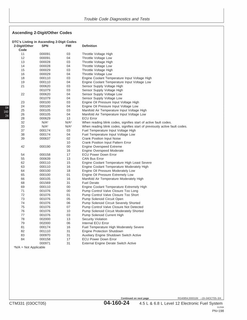
Trouble Code Diagnostics and Tests
04160
24
RG40854,0000106 –19–04OCT05–3/4
Ascending 2-Digit/Other Codes
DTC’s Listing in Ascending 2-Digit Codes2-Digit/Other SPN FMI Definition
Code11 000091 03 Throttle Voltage High12 000091 04 Throttle Voltage Low13 000028 03 Throttle Voltage High14 000028 04 Throttle Voltage Low15 000029 03 Throttle Voltage High16 000029 04 Throttle Voltage Low18 000110 03 Engine Coolant Temperature Input Voltage High19 000110 04 Engine Coolant Temperature Input Voltage Low21 000620 03 Sensor Supply Voltage High
001079 03 Sensor Supply Voltage High22 000620 04 Sensor Supply Voltage Low
001079 04 Sensor Supply Voltage Low23 000100 03 Engine Oil Pressure Input Voltage High24 000100 04 Engine Oil Pressure Input Voltage Low25 000105 03 Manifold Air Temperature Input Voltage High26 000105 04 Manifold Air Temperature Input Voltage Low28 000629 13 ECU Error32 N/Aa N/Aa When reading blink codes, signifies start of active fault codes.33 N/Aa N/Aa When reading blink codes, signifies start of previously active fault codes.37 000174 03 Fuel Temperature Input Voltage High38 000174 04 Fuel Temperature Input Voltage Low39 000637 02 Crank Position Input Noise
10 Crank Position Input Pattern Error42 000190 00 Engine Overspeed Extreme
16 Engine Overspeed Moderate54 000158 17 ECU Power Down Error55 000639 13 CAN Bus Error62 000110 15 Engine Coolant Temperature High Least Severe63 000110 16 Engine Coolant Temperature Moderately High64 000100 18 Engine Oil Pressure Moderately Low65 000100 01 Engine Oil Pressure Extremely Low66 000105 16 Manifold Air Temperature Moderately High68 001569 31 Fuel Derate69 000110 00 Engine Coolant Temperature Extremely High71 001076 00 Pump Control Valve Closure Too Long72 001076 01 Pump Control Valve Closure Too Short73 001076 05 Pump Solenoid Circuit Open74 001076 06 Pump Solenoid Circuit Severely Shorted75 001076 07 Pump Control Valve Closure Not Detected76 001076 10 Pump Solenoid Circuit Moderately Shorted77 001076 03 Pump Solenoid Current High78 002000 13 Security Violation79 002000 06 Internal ECU Error81 000174 16 Fuel Temperature High Moderately Severe82 001110 31 Engine Protection Shutdown83 000970 31 Auxiliary Engine Shutdown Switch Active84 000158 17 ECU Power Down Error
000971 31 External Engine Derate Switch ActiveaN/A = Not Applicable
CTM331 (03OCT05) 04-160-24 4.5 L & 6.8 L Level 12 Electronic Fuel System012506
PN=198
Continued on next page
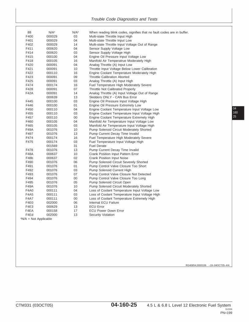
Trouble Code Diagnostics and Tests
0416025
RG40854,0000106 –19–04OCT05–4/4
88 N/Aa N/Aa When reading blink codes, signifies that no fault codes are in buffer.F400 000029 03 Multi-state Throttle Input HighF401 000029 04 Multi-state Throttle Input LowF402 000029 14 Multi-state Throttle Input Voltage Out of RangeF411 000620 04 Sensor Supply Voltage LowF414 000620 03 Sensor Supply Voltage HighF415 000100 04 Engine Oil Pressure Input Voltage LowF418 000105 16 Manifold Air Temperatrue Moderately HighF420 000091 04 Analog Throttle (A) Input LowF421 000091 10 Throttle Input Voltage Below Lower CalibrationF422 000110 16 Engine Coolant Temperature Moderately HighF423 000091 09 Throttle Calibration AbortedF425 000091 03 Analog Throttle (A) Input HighF474 000174 16 Fuel Temperature High Moderately SevereF428 000091 07 Throttle Not Calibrated ProperlyF42A 000091 14 Analog Throttle (A) Input Voltage Out of Range
000639 13 Skidders ONLY - CAN Bus ErrorF445 000100 03 Engine Oil Pressure Input Voltage HighF446 000100 01 Engine Oil Pressure Extremely LowF450 000110 04 Engine Coolant Temperature Input Voltage LowF455 000110 03 Engine Coolant Temperature Input Voltage HighF457 000110 00 Engine Coolant Temperature Extremely HighF460 000105 04 Manifold Air Temperature Input Voltage LowF465 000105 03 Manifold Air Temperature Input Voltage HighF49A 001076 10 Pump Solenoid Circuit Moderately ShortedF497 001076 13 Pump Current Decay Time InvalidF474 000174 16 Fuel Temperature High Moderately SevereF475 000174 03 Fuel Temperature Input Voltage High
001569 31 Fuel DerateF478 001076 13 Pump Current Decay Time InvalidF48A 000637 10 Crank Position Input Pattern ErrorF48b 000637 02 Crank Position Input NoiseF490 001076 06 Pump Solenoid Circuit Severely ShortedF491 001076 01 Pump Control Valve Closure Too ShortF492 001076 03 Pump Solenoid Current HighF493 001076 07 Pump Control Valve Closure Not DetectedF494 001076 00 Pump Control Valve Closure Too LongF495 001076 05 Pump Solenoid Circuit OpenF49A 001076 10 Pump Solenoid Circuit Moderately ShortedF4A0 000111 04 Loss of Coolant Temperature Input Voltage LowF4A5 000111 03 Loss of Coolant Temperature Input Voltage HighF4A7 000111 00 Loss of Coolant Temperature Extremely HighF4E0 002000 06 Internal ECU FailureF4E3 000629 13 ECU ErrorF4EA 000158 17 ECU Power Down ErrorF4Ed 002000 13 Security Violation
aN/A = Not Applicable
CTM331 (03OCT05) 04-160-25 4.5 L & 6.8 L Level 12 Electronic Fuel System012506
PN=199
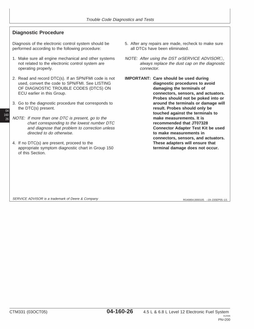
Trouble Code Diagnostics and Tests
04160
26
RG40854,0000105 –19–23SEP05–1/1
Diagnostic Procedure
Diagnosis of the electronic control system should beperformed according to the following procedure:
1. Make sure all engine mechanical and other systemsnot related to the electronic control system areoperating properly.
2. Read and record DTC(s). If an SPN/FMI code is notused, convert the code to SPN/FMI. See LISTINGOF DIAGNOSTIC TROUBLE CODES (DTCS) ONECU earlier in this Group.
3. Go to the diagnostic procedure that corresponds tothe DTC(s) present.
NOTE: If more than one DTC is present, go to thechart corresponding to the lowest number DTCand diagnose that problem to correction unlessdirected to do otherwise.
4. If no DTC(s) are present, proceed to theappropriate symptom diagnostic chart in Group 150of this Section.
5. After any repairs are made, recheck to make sureall DTCs have been eliminated.
NOTE: After using the DST orSERVICE ADVISOR,always replace the dust cap on the diagnosticconnector.
IMPORTANT: Care should be used duringdiagnostic procedures to avoiddamaging the terminals ofconnectors, sensors, and actuators.Probes should not be poked into oraround the terminals or damage willresult. Probes should only betouched against the terminals tomake measurements. It isrecommended that JT07328Connector Adapter Test Kit be usedto make measurements inconnectors, sensors, and actuators.These adapters will ensure thatterminal damage does not occur.
SERVICE ADVISOR is a trademark of Deere & Company
CTM331 (03OCT05) 04-160-26 4.5 L & 6.8 L Level 12 Electronic Fuel System012506
PN=200
Trouble Code Diagnostics and Tests
0416027
RG40854,0000107 –19–23SEP05–1/1
Intermittent Fault Diagnostics
Intermittent faults are problems that periodically “goaway”. A problem such as a loose terminal thatintermittently doesn’t make contact is a likely cause ofan intermittent fault. Other intermittent faults may beset only under certain operating conditions such asheavy load, extended idle, etc. When diagnosingintermittent faults, take special note of the condition ofwiring and connectors since a high percentage ofintermittent problems originate here. Check for loose,dirty, or disconnected connectors. Inspect the wiringrouting looking for possible shorts caused by contactwith external parts (for example, rubbing against sharpsheet metal edges). Inspect the connector vicinitylooking for wires that have pulled out of connectorterminals, damaged connectors, poorly positionedterminals, and corroded or damaged terminals. Lookfor broken wires, damaged splices, and wire-to-wireshorts. Use good judgement if component replacementis thought to be required.
NOTE: The ECU is the component LEAST likely tofail.
Suggestions for diagnosing intermittent faults:
• If diagnostic chart indicates that the problem isintermittent, try to reproduce the operating conditionsthat were present when the DTC set. The DSTorSERVICE ADVISOR can be used to help locateintermittent problems, as it includes a function called
Recording. This function permits the recording ofdata parameter values during a diagnostic session. Ifa DTC sets during a certain diagnostic session, theparameters can be played back and observed to seewhat each parameters’ value was when the DTCoccurred.
• If a faulty connection or wire is suspected to be thecause of the intermittent problem: clear DTCs, thencheck the connection or wire by wiggling it whilewatching the DST orSERVICE ADVISOR to see ifthe fault resets.
• To check the connection between the harness and asensor or the harness and the ECU, use JT07328Connector Adapter Test Kit. Insert the male end ofthe appropriate test adapter into the female end ofthe ECU or sensor connector terminal. There shouldbe moderate resistance when the test adapter isinserted into the terminal. If the connection is loose,replace the female terminal.
Possible Causes of Intermittent Faults:
• Faulty connection between sensor or actuator andharness.
• Faulty contact between terminals in connector.• Faulty terminal/wire connection.• Electromagnetic interference (EMI) from an
improperly installed 2-way radio, etc. can causefaulty signals to be sent to the ECU.
SERVICE ADVISOR is a trademark of Deere & Company
CTM331 (03OCT05) 04-160-27 4.5 L & 6.8 L Level 12 Electronic Fuel System012506
PN=201
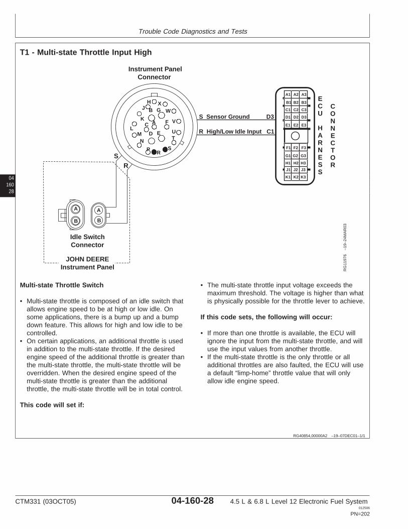
Trouble Code Diagnostics and Tests
04160
28
RG40854,00000A2 –19–07DEC01–1/1
T1 - Multi-state Throttle Input High
Instrument PanelConnector
Idle SwitchConnector
G
C A F
ED
BX
W
V
UT
SR
P
NM
L
K
J
R High/Low Idle Input C1
R
S Sensor Ground D3
S
JOHN DEEREInstrument Panel
H
A
B
A
B
A1 A2 A3
B3
C3
D3
E3
B2
C2
D2
E2
B1
C1
D1
E1
F1 F2 F3
G3
H3
J3
K3
G2
H2
J2
K2
G1
H1
J1
K1
ECU
HARNESS
CONNECTOR
RG
1197
6–1
9–24
MA
R03
Multi-state Throttle Switch
• Multi-state throttle is composed of an idle switch thatallows engine speed to be at high or low idle. Onsome applications, there is a bump up and a bumpdown feature. This allows for high and low idle to becontrolled.
• On certain applications, an additional throttle is usedin addition to the multi-state throttle. If the desiredengine speed of the additional throttle is greater thanthe multi-state throttle, the multi-state throttle will beoverridden. When the desired engine speed of themulti-state throttle is greater than the additionalthrottle, the multi-state throttle will be in total control.
This code will set if:
• The multi-state throttle input voltage exceeds themaximum threshold. The voltage is higher than whatis physically possible for the throttle lever to achieve.
If this code sets, the following will occur:
• If more than one throttle is available, the ECU willignore the input from the multi-state throttle, and willuse the input values from another throttle.
• If the multi-state throttle is the only throttle or alladditional throttles are also faulted, the ECU will usea default “limp-home” throttle value that will onlyallow idle engine speed.
CTM331 (03OCT05) 04-160-28 4.5 L & 6.8 L Level 12 Electronic Fuel System012506
PN=202

Trouble Code Diagnostics and Tests
RG40854,00000A1 –19–23SEP05–1/1
T1 - Multi-state Throttle Input High
– – –1/1
T1 - Multi-State Throttle Input High Diagnostic Procedure
0416029
– – –1/1
1 Connection Check IMPORTANT: Do not force probes into connector terminals or damage will result.Use JT07328 Connector Adapter Test Kit to make measurements in connectors.This will ensure that terminal damage does not occur.
NOTE: For wiring and theory of operation, see T1 - MULTI-STATE THROTTLE INPUTHIGH supporting information.
Perform a preliminary inspection of the ECU connector and the multi-state throttleconnector. Look for dirty, damaged, or poorly positioned terminals.
No faulty connection(s):GO TO 2
Faulty connection(s):Repair faultyconnection(s)
– – –1/1
2 Intermittent Fault Test NOTE: For wiring and theory of operation, see T1 - MULTI-STATE THROTTLE INPUTHIGH supporting information.
1. Connect to the DST orSERVICE ADVISOR.
2. Ignition ON, engine OFF
3. Start the ECU communication software
4. Read DTCs using the DST orSERVICE ADVISOR
5. Make note of any DTCs, then clear all DTCs.
6. Ignition ON, engine OFF
7. Move the multi-state switch through all the positions.
8. Read DTCs using the DST orSERVICE ADVISOR.
NOTE: Skidder applications use a different SPN for multi-state throttle than otherapplications.
000091.03 (Skidders:000029.03) reoccurs:GO TO 3
000091.03 (Skidders:000029.03) does notreoccur:Problem is intermittent. Ifno other codes arepresent, seeINTERMITTENT FAULTDIAGNOSTICS earlier inthis Group.
SERVICE ADVISOR is a trademark of Deere & Company
CTM331 (03OCT05) 04-160-29 4.5 L & 6.8 L Level 12 Electronic Fuel System012506
PN=203
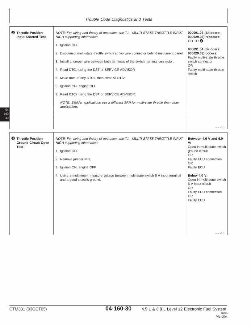
Trouble Code Diagnostics and Tests
04160
30
– – –1/1
3 Throttle PositionInput Shorted Test
NOTE: For wiring and theory of operation, see T1 - MULTI-STATE THROTTLE INPUTHIGH supporting information.
1. Ignition OFF
2. Disconnect multi-state throttle switch at two wire connector behind instrument panel.
3. Install a jumper wire between both terminals of the switch harness connector.
4. Read DTCs using the DST or SERVICE ADVISOR
5. Make note of any DTCs, then clear all DTCs
6. Ignition ON, engine OFF
7. Read DTCs using the DST or SERVICE ADVISOR.
NOTE: Skidder applications use a different SPN for multi-state throttle than otherapplications.
000091.03 (Skidders:000029.03) reoccurs:GO TO 4
000091.04 (Skidders:000029.03) occurs:Faulty multi-state throttleswitch connectorORFaulty multi-state throttleswitch
– – –1/1
4 Throttle PositionGround Circuit OpenTest
NOTE: For wiring and theory of operation, see T1 - MULTI-STATE THROTTLE INPUTHIGH supporting information.
1. Ignition OFF
2. Remove jumper wire.
3. Ignition ON, engine OFF
4. Using a multimeter, measure voltage between multi-state switch 5 V input terminaland a good chassis ground.
Between 4.0 V and 6.0V:Open in multi-state switchground circuitORFaulty ECU connectionORFaulty ECU
Below 4.0 V:Open in multi-state switch5 V input circuitORFaulty ECU connectionORFaulty ECU
CTM331 (03OCT05) 04-160-30 4.5 L & 6.8 L Level 12 Electronic Fuel System012506
PN=204

Trouble Code Diagnostics and Tests
0416031
CTM331 (03OCT05) 04-160-31 4.5 L & 6.8 L Level 12 Electronic Fuel System012506
PN=205
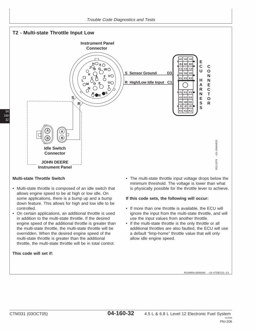
Trouble Code Diagnostics and Tests
04160
32
RG40854,00000A0 –19–07DEC01–1/1
T2 - Multi-state Throttle Input Low
Instrument PanelConnector
Idle SwitchConnector
G
C A F
ED
BX
W
V
UT
SR
P
NM
L
K
J
R High/Low Idle Input C1
R
S Sensor Ground D3
S
JOHN DEEREInstrument Panel
H
A
B
A
B
A1 A2 A3
B3
C3
D3
E3
B2
C2
D2
E2
B1
C1
D1
E1
F1 F2 F3
G3
H3
J3
K3
G2
H2
J2
K2
G1
H1
J1
K1
ECU
HARNESS
CONNECTOR
RG
1197
6–1
9–24
MA
R03
Multi-state Throttle Switch
• Multi-state throttle is composed of an idle switch thatallows engine speed to be at high or low idle. Onsome applications, there is a bump up and a bumpdown feature. This allows for high and low idle to becontrolled.
• On certain applications, an additional throttle is usedin addition to the multi-state throttle. If the desiredengine speed of the additional throttle is greater thanthe multi-state throttle, the multi-state throttle will beoverridden. When the desired engine speed of themulti-state throttle is greater than the additionalthrottle, the multi-state throttle will be in total control.
This code will set if:
• The multi-state throttle input voltage drops below theminimum threshold. The voltage is lower than whatis physically possible for the throttle lever to achieve.
If this code sets, the following will occur:
• If more than one throttle is available, the ECU willignore the input from the multi-state throttle, and willuse the input values from another throttle.
• If the multi-state throttle is the only throttle or alladditional throttles are also faulted, the ECU will usea default “limp-home” throttle value that will onlyallow idle engine speed.
CTM331 (03OCT05) 04-160-32 4.5 L & 6.8 L Level 12 Electronic Fuel System012506
PN=206
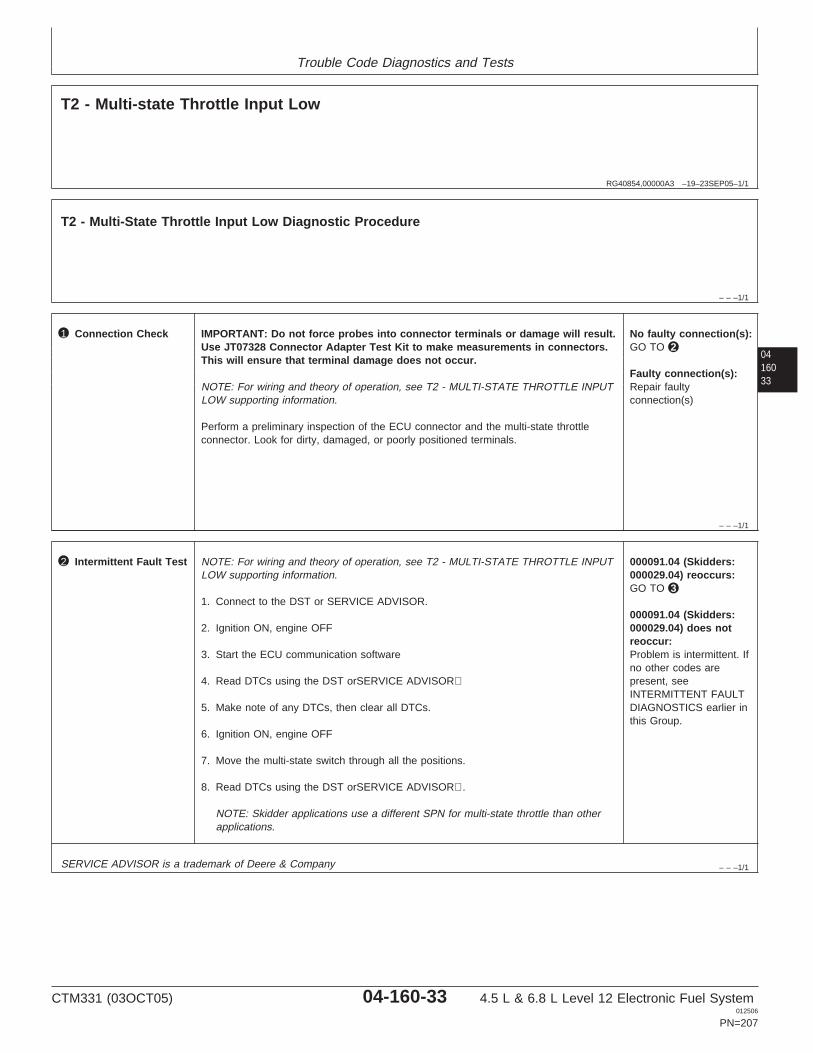
Trouble Code Diagnostics and Tests
RG40854,00000A3 –19–23SEP05–1/1
T2 - Multi-state Throttle Input Low
– – –1/1
T2 - Multi-State Throttle Input Low Diagnostic Procedure
0416033
– – –1/1
1 Connection Check IMPORTANT: Do not force probes into connector terminals or damage will result.Use JT07328 Connector Adapter Test Kit to make measurements in connectors.This will ensure that terminal damage does not occur.
NOTE: For wiring and theory of operation, see T2 - MULTI-STATE THROTTLE INPUTLOW supporting information.
Perform a preliminary inspection of the ECU connector and the multi-state throttleconnector. Look for dirty, damaged, or poorly positioned terminals.
No faulty connection(s):GO TO 2
Faulty connection(s):Repair faultyconnection(s)
– – –1/1
2 Intermittent Fault Test NOTE: For wiring and theory of operation, see T2 - MULTI-STATE THROTTLE INPUTLOW supporting information.
1. Connect to the DST or SERVICE ADVISOR.
2. Ignition ON, engine OFF
3. Start the ECU communication software
4. Read DTCs using the DST orSERVICE ADVISOR
5. Make note of any DTCs, then clear all DTCs.
6. Ignition ON, engine OFF
7. Move the multi-state switch through all the positions.
8. Read DTCs using the DST orSERVICE ADVISOR.
NOTE: Skidder applications use a different SPN for multi-state throttle than otherapplications.
000091.04 (Skidders:000029.04) reoccurs:GO TO 3
000091.04 (Skidders:000029.04) does notreoccur:Problem is intermittent. Ifno other codes arepresent, seeINTERMITTENT FAULTDIAGNOSTICS earlier inthis Group.
SERVICE ADVISOR is a trademark of Deere & Company
CTM331 (03OCT05) 04-160-33 4.5 L & 6.8 L Level 12 Electronic Fuel System012506
PN=207
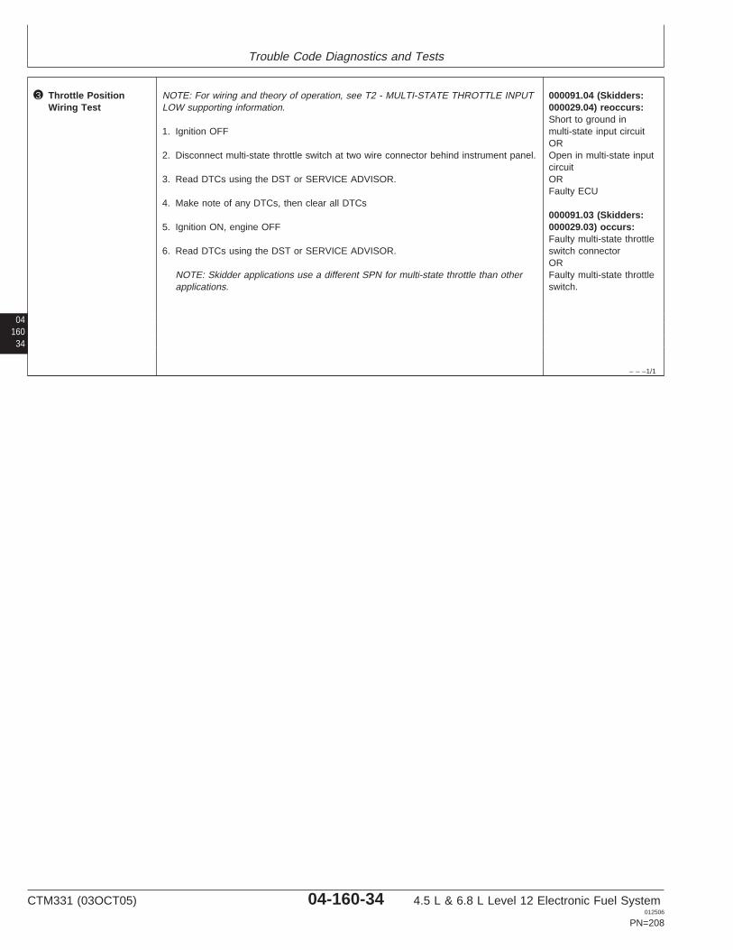
Trouble Code Diagnostics and Tests
04160
34
– – –1/1
3 Throttle PositionWiring Test
NOTE: For wiring and theory of operation, see T2 - MULTI-STATE THROTTLE INPUTLOW supporting information.
1. Ignition OFF
2. Disconnect multi-state throttle switch at two wire connector behind instrument panel.
3. Read DTCs using the DST or SERVICE ADVISOR.
4. Make note of any DTCs, then clear all DTCs
5. Ignition ON, engine OFF
6. Read DTCs using the DST or SERVICE ADVISOR.
NOTE: Skidder applications use a different SPN for multi-state throttle than otherapplications.
000091.04 (Skidders:000029.04) reoccurs:Short to ground inmulti-state input circuitOROpen in multi-state inputcircuitORFaulty ECU
000091.03 (Skidders:000029.03) occurs:Faulty multi-state throttleswitch connectorORFaulty multi-state throttleswitch.
CTM331 (03OCT05) 04-160-34 4.5 L & 6.8 L Level 12 Electronic Fuel System012506
PN=208

Trouble Code Diagnostics and Tests
0416035
CTM331 (03OCT05) 04-160-35 4.5 L & 6.8 L Level 12 Electronic Fuel System012506
PN=209
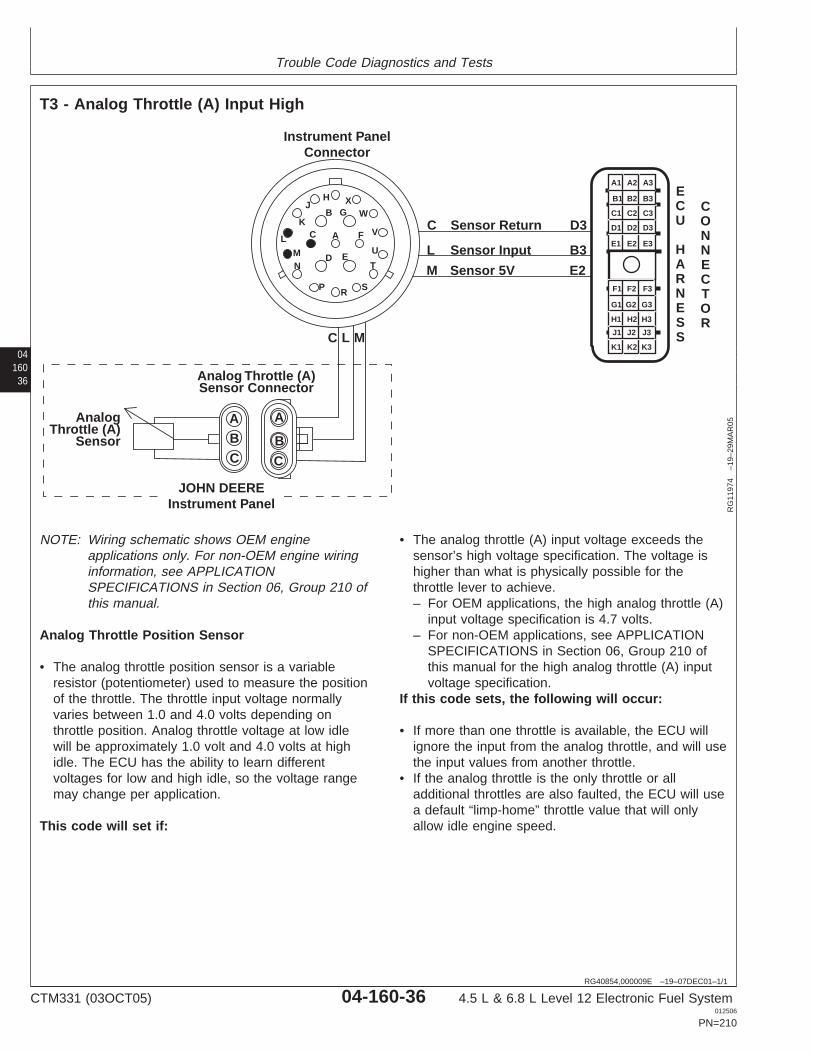
Trouble Code Diagnostics and Tests
04160
36
RG40854,000009E –19–07DEC01–1/1
T3 - Analog Throttle (A) Input High
Analog Throttle (A)Sensor Connector
AnalogThrottle (A)
Sensor
A A
B BC C
Instrument PanelConnector
G
C A F
ED
BX
W
V
U
T
SRP
NM
L
K
JH
C Sensor Return D3
L Sensor Input B3
M Sensor 5V E2
C L M
JOHN DEEREInstrument Panel
A1 A2 A3
B3
C3
D3
E3
B2
C2
D2
E2
B1
C1
D1
E1
F1 F2 F3
G3
H3
J3
K3
G2
H2
J2
K2
G1
H1
J1
K1
ECU
HARNESS
CONNECTOR
RG
1197
4–1
9–29
MA
R05
NOTE: Wiring schematic shows OEM engineapplications only. For non-OEM engine wiringinformation, see APPLICATIONSPECIFICATIONS in Section 06, Group 210 ofthis manual.
Analog Throttle Position Sensor
• The analog throttle position sensor is a variableresistor (potentiometer) used to measure the positionof the throttle. The throttle input voltage normallyvaries between 1.0 and 4.0 volts depending onthrottle position. Analog throttle voltage at low idlewill be approximately 1.0 volt and 4.0 volts at highidle. The ECU has the ability to learn differentvoltages for low and high idle, so the voltage rangemay change per application.
This code will set if:
• The analog throttle (A) input voltage exceeds thesensor’s high voltage specification. The voltage ishigher than what is physically possible for thethrottle lever to achieve.– For OEM applications, the high analog throttle (A)
input voltage specification is 4.7 volts.– For non-OEM applications, see APPLICATION
SPECIFICATIONS in Section 06, Group 210 ofthis manual for the high analog throttle (A) inputvoltage specification.
If this code sets, the following will occur:
• If more than one throttle is available, the ECU willignore the input from the analog throttle, and will usethe input values from another throttle.
• If the analog throttle is the only throttle or alladditional throttles are also faulted, the ECU will usea default “limp-home” throttle value that will onlyallow idle engine speed.
CTM331 (03OCT05) 04-160-36 4.5 L & 6.8 L Level 12 Electronic Fuel System012506
PN=210
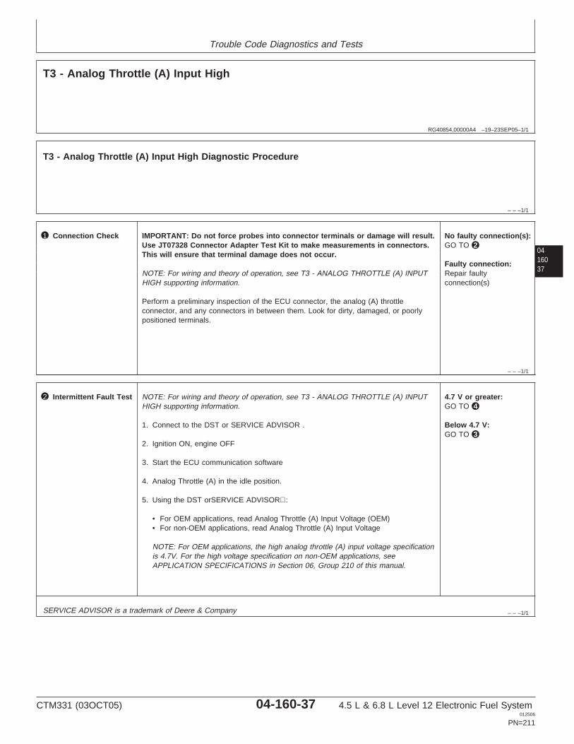
Trouble Code Diagnostics and Tests
RG40854,00000A4 –19–23SEP05–1/1
T3 - Analog Throttle (A) Input High
– – –1/1
T3 - Analog Throttle (A) Input High Diagnostic Procedure
0416037
– – –1/1
1 Connection Check IMPORTANT: Do not force probes into connector terminals or damage will result.Use JT07328 Connector Adapter Test Kit to make measurements in connectors.This will ensure that terminal damage does not occur.
NOTE: For wiring and theory of operation, see T3 - ANALOG THROTTLE (A) INPUTHIGH supporting information.
Perform a preliminary inspection of the ECU connector, the analog (A) throttleconnector, and any connectors in between them. Look for dirty, damaged, or poorlypositioned terminals.
No faulty connection(s):GO TO 2
Faulty connection:Repair faultyconnection(s)
– – –1/1
2 Intermittent Fault Test NOTE: For wiring and theory of operation, see T3 - ANALOG THROTTLE (A) INPUTHIGH supporting information.
1. Connect to the DST or SERVICE ADVISOR .
2. Ignition ON, engine OFF
3. Start the ECU communication software
4. Analog Throttle (A) in the idle position.
5. Using the DST orSERVICE ADVISOR:
• For OEM applications, read Analog Throttle (A) Input Voltage (OEM)• For non-OEM applications, read Analog Throttle (A) Input Voltage
NOTE: For OEM applications, the high analog throttle (A) input voltage specificationis 4.7V. For the high voltage specification on non-OEM applications, seeAPPLICATION SPECIFICATIONS in Section 06, Group 210 of this manual.
4.7 V or greater:GO TO 4
Below 4.7 V:GO TO 3
SERVICE ADVISOR is a trademark of Deere & Company
CTM331 (03OCT05) 04-160-37 4.5 L & 6.8 L Level 12 Electronic Fuel System012506
PN=211
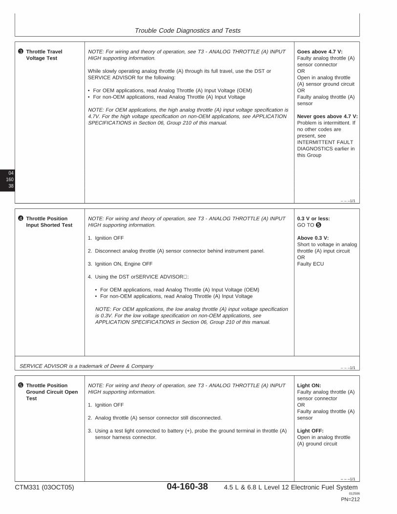
Trouble Code Diagnostics and Tests
04160
38
– – –1/1
3 Throttle TravelVoltage Test
NOTE: For wiring and theory of operation, see T3 - ANALOG THROTTLE (A) INPUTHIGH supporting information.
While slowly operating analog throttle (A) through its full travel, use the DST orSERVICE ADVISOR for the following:
• For OEM applications, read Analog Throttle (A) Input Voltage (OEM)• For non-OEM applications, read Analog Throttle (A) Input Voltage
NOTE: For OEM applications, the high analog throttle (A) input voltage specification is4.7V. For the high voltage specification on non-OEM applications, see APPLICATIONSPECIFICATIONS in Section 06, Group 210 of this manual.
Goes above 4.7 V:Faulty analog throttle (A)sensor connectorOROpen in analog throttle(A) sensor ground circuitORFaulty analog throttle (A)sensor
Never goes above 4.7 V:Problem is intermittent. Ifno other codes arepresent, seeINTERMITTENT FAULTDIAGNOSTICS earlier inthis Group
– – –1/1
4 Throttle PositionInput Shorted Test
NOTE: For wiring and theory of operation, see T3 - ANALOG THROTTLE (A) INPUTHIGH supporting information.
1. Ignition OFF
2. Disconnect analog throttle (A) sensor connector behind instrument panel.
3. Ignition ON, Engine OFF
4. Using the DST orSERVICE ADVISOR:
• For OEM applications, read Analog Throttle (A) Input Voltage (OEM)• For non-OEM applications, read Analog Throttle (A) Input Voltage
NOTE: For OEM applications, the low analog throttle (A) input voltage specificationis 0.3V. For the low voltage specification on non-OEM applications, seeAPPLICATION SPECIFICATIONS in Section 06, Group 210 of this manual.
0.3 V or less:GO TO 5
Above 0.3 V:Short to voltage in analogthrottle (A) input circuitORFaulty ECU
SERVICE ADVISOR is a trademark of Deere & Company
– – –1/1
5 Throttle PositionGround Circuit OpenTest
NOTE: For wiring and theory of operation, see T3 - ANALOG THROTTLE (A) INPUTHIGH supporting information.
1. Ignition OFF
2. Analog throttle (A) sensor connector still disconnected.
3. Using a test light connected to battery (+), probe the ground terminal in throttle (A)sensor harness connector.
Light ON:Faulty analog throttle (A)sensor connectorORFaulty analog throttle (A)sensor
Light OFF:Open in analog throttle(A) ground circuit
CTM331 (03OCT05) 04-160-38 4.5 L & 6.8 L Level 12 Electronic Fuel System012506
PN=212

Trouble Code Diagnostics and Tests
0416039
CTM331 (03OCT05) 04-160-39 4.5 L & 6.8 L Level 12 Electronic Fuel System012506
PN=213
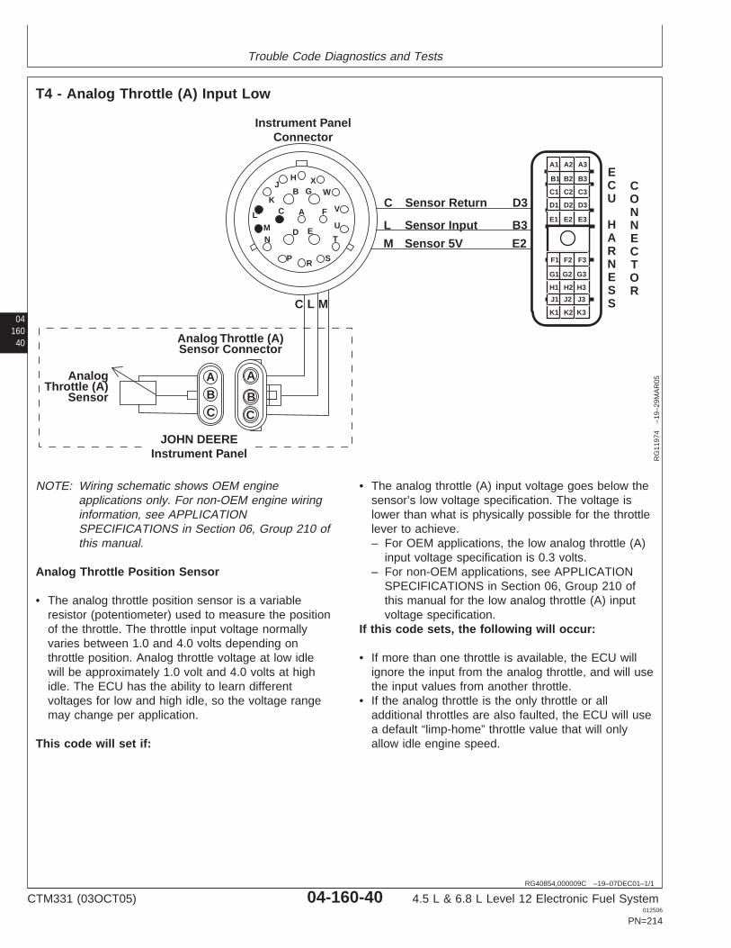
Trouble Code Diagnostics and Tests
04160
40
RG40854,000009C –19–07DEC01–1/1
T4 - Analog Throttle (A) Input Low
Analog Throttle (A)Sensor Connector
AnalogThrottle (A)
Sensor
A A
B BC C
Instrument PanelConnector
G
C A F
ED
BX
W
V
U
T
SRP
NM
L
K
JH
C Sensor Return D3
L Sensor Input B3
M Sensor 5V E2
C L M
JOHN DEEREInstrument Panel
A1 A2 A3
B3
C3
D3
E3
B2
C2
D2
E2
B1
C1
D1
E1
F1 F2 F3
G3
H3
J3
K3
G2
H2
J2
K2
G1
H1
J1
K1
ECU
HARNESS
CONNECTOR
RG
1197
4–1
9–29
MA
R05
NOTE: Wiring schematic shows OEM engineapplications only. For non-OEM engine wiringinformation, see APPLICATIONSPECIFICATIONS in Section 06, Group 210 ofthis manual.
Analog Throttle Position Sensor
• The analog throttle position sensor is a variableresistor (potentiometer) used to measure the positionof the throttle. The throttle input voltage normallyvaries between 1.0 and 4.0 volts depending onthrottle position. Analog throttle voltage at low idlewill be approximately 1.0 volt and 4.0 volts at highidle. The ECU has the ability to learn differentvoltages for low and high idle, so the voltage rangemay change per application.
This code will set if:
• The analog throttle (A) input voltage goes below thesensor’s low voltage specification. The voltage islower than what is physically possible for the throttlelever to achieve.– For OEM applications, the low analog throttle (A)
input voltage specification is 0.3 volts.– For non-OEM applications, see APPLICATION
SPECIFICATIONS in Section 06, Group 210 ofthis manual for the low analog throttle (A) inputvoltage specification.
If this code sets, the following will occur:
• If more than one throttle is available, the ECU willignore the input from the analog throttle, and will usethe input values from another throttle.
• If the analog throttle is the only throttle or alladditional throttles are also faulted, the ECU will usea default “limp-home” throttle value that will onlyallow idle engine speed.
CTM331 (03OCT05) 04-160-40 4.5 L & 6.8 L Level 12 Electronic Fuel System012506
PN=214

Trouble Code Diagnostics and Tests
RG40854,00000A5 –19–23SEP05–1/1
T4 - Analog Throttle (A) Input Low
– – –1/1
T4 - Analog Throttle (A) Input Low Diagnostic Procedure
0416041
– – –1/1
1 Connection Check IMPORTANT: Do not force probes into connector terminals or damage will result.Use JT07328 Connector Adapter Test Kit to make measurements in connectors.This will ensure that terminal damage does not occur.
NOTE: For wiring and theory of operation, see T4 - ANALOG THROTTLE (A) INPUTLOW supporting information.
Perform a preliminary inspection of the ECU connector, the analog (A) throttleconnector, and any connectors in between them. Look for dirty, damaged, or poorlypositioned terminals.
No faulty connection(s):GO TO 2
Faulty connection:Repair faulty connection.
– – –1/1
2 Intermittent Fault Test NOTE: For wiring and theory of operation, see T4 - ANALOG THROTTLE (A) INPUTLOW supporting information.
1. Connect to the DST or SERVICE ADVISOR .
2. Ignition ON, engine OFF
3. Start the ECU communication software
4. Throttle (A) in the idle position.
5. Using the DST orSERVICE ADVISOR:
• For OEM applications, read Analog Throttle (A) Input Voltage (OEM)• For non-OEM applications, read Analog Throttle (A) Input Voltage
NOTE: For OEM applications, the low analog throttle (A) input voltage specificationis 0.3V. For the low voltage specification on non-OEM applications, seeAPPLICATION SPECIFICATIONS in Section 06, Group 210 of this manual.
0.3 V or less:GO TO 4
Above 0.3 V:GO TO 3
SERVICE ADVISOR is a trademark of Deere & Company
CTM331 (03OCT05) 04-160-41 4.5 L & 6.8 L Level 12 Electronic Fuel System012506
PN=215
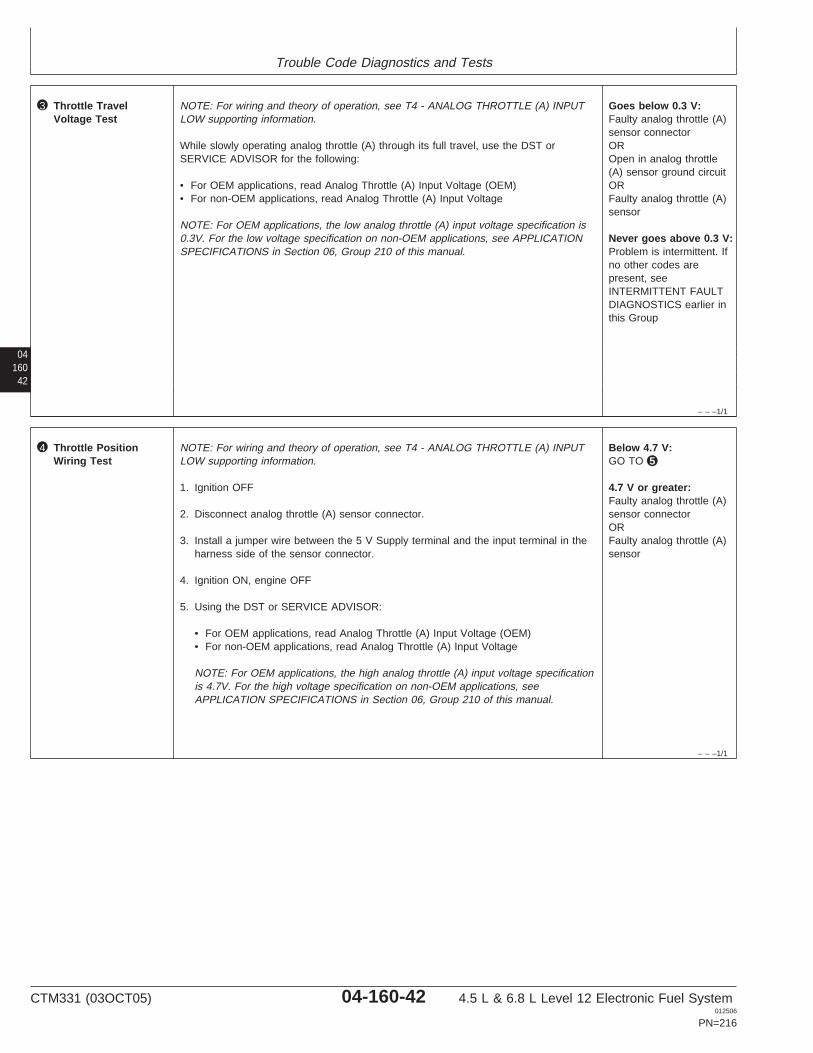
Trouble Code Diagnostics and Tests
04160
42
– – –1/1
3 Throttle TravelVoltage Test
NOTE: For wiring and theory of operation, see T4 - ANALOG THROTTLE (A) INPUTLOW supporting information.
While slowly operating analog throttle (A) through its full travel, use the DST orSERVICE ADVISOR for the following:
• For OEM applications, read Analog Throttle (A) Input Voltage (OEM)• For non-OEM applications, read Analog Throttle (A) Input Voltage
NOTE: For OEM applications, the low analog throttle (A) input voltage specification is0.3V. For the low voltage specification on non-OEM applications, see APPLICATIONSPECIFICATIONS in Section 06, Group 210 of this manual.
Goes below 0.3 V:Faulty analog throttle (A)sensor connectorOROpen in analog throttle(A) sensor ground circuitORFaulty analog throttle (A)sensor
Never goes above 0.3 V:Problem is intermittent. Ifno other codes arepresent, seeINTERMITTENT FAULTDIAGNOSTICS earlier inthis Group
– – –1/1
4 Throttle PositionWiring Test
NOTE: For wiring and theory of operation, see T4 - ANALOG THROTTLE (A) INPUTLOW supporting information.
1. Ignition OFF
2. Disconnect analog throttle (A) sensor connector.
3. Install a jumper wire between the 5 V Supply terminal and the input terminal in theharness side of the sensor connector.
4. Ignition ON, engine OFF
5. Using the DST or SERVICE ADVISOR:
• For OEM applications, read Analog Throttle (A) Input Voltage (OEM)• For non-OEM applications, read Analog Throttle (A) Input Voltage
NOTE: For OEM applications, the high analog throttle (A) input voltage specificationis 4.7V. For the high voltage specification on non-OEM applications, seeAPPLICATION SPECIFICATIONS in Section 06, Group 210 of this manual.
Below 4.7 V:GO TO 5
4.7 V or greater:Faulty analog throttle (A)sensor connectorORFaulty analog throttle (A)sensor
CTM331 (03OCT05) 04-160-42 4.5 L & 6.8 L Level 12 Electronic Fuel System012506
PN=216
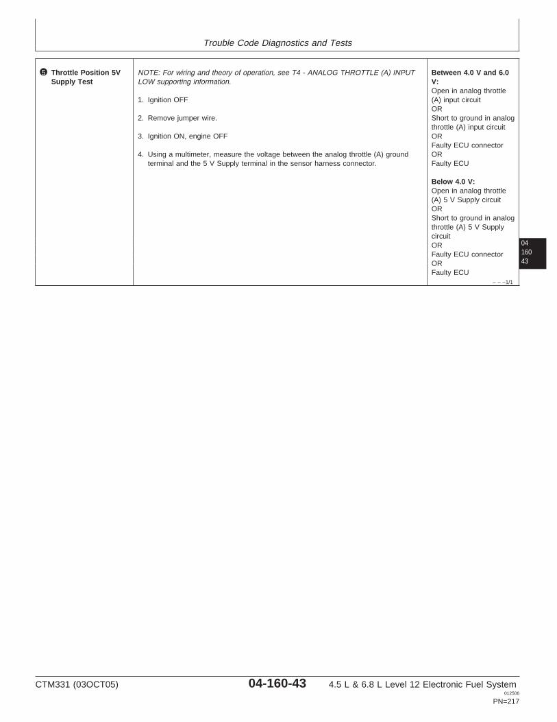
Trouble Code Diagnostics and Tests
0416043
– – –1/1
5 Throttle Position 5VSupply Test
NOTE: For wiring and theory of operation, see T4 - ANALOG THROTTLE (A) INPUTLOW supporting information.
1. Ignition OFF
2. Remove jumper wire.
3. Ignition ON, engine OFF
4. Using a multimeter, measure the voltage between the analog throttle (A) groundterminal and the 5 V Supply terminal in the sensor harness connector.
Between 4.0 V and 6.0V:Open in analog throttle(A) input circuitORShort to ground in analogthrottle (A) input circuitORFaulty ECU connectorORFaulty ECU
Below 4.0 V:Open in analog throttle(A) 5 V Supply circuitORShort to ground in analogthrottle (A) 5 V SupplycircuitORFaulty ECU connectorORFaulty ECU
CTM331 (03OCT05) 04-160-43 4.5 L & 6.8 L Level 12 Electronic Fuel System012506
PN=217
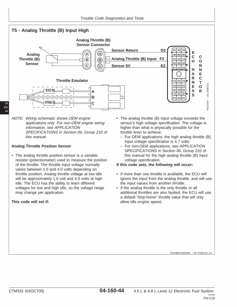
Trouble Code Diagnostics and Tests
04160
44
RG40854,000009A –19–07DEC01–1/1
T5 - Analog Throttle (B) Input High
Sensor Return D3
Analog Throttle (B) Input F2
Sensor 5V E2
Analog Throttle (B)Sensor Connector
Throttle Emulator
AnalogThrottle (B)
Sensor
A
A A
B B
C C
B
C
A1 A2 A3
B3
C3
D3
E3
B2
C2
D2
E2
B1
C1
D1
E1
F1 F2 F3
G3
H3
J3
K3
G2
H2
J2
K2
G1
H1
J1
K1
ECU
HARNESS
CONNECTOR
RG
1197
5–1
9–14
DE
C01
NOTE: Wiring schematic shows OEM engineapplications only. For non-OEM engine wiringinformation, see APPLICATIONSPECIFICATIONS in Section 06, Group 210 ofthis manual.
Analog Throttle Position Sensor
• The analog throttle position sensor is a variableresistor (potentiometer) used to measure the positionof the throttle. The throttle input voltage normallyvaries between 1.0 and 4.0 volts depending onthrottle position. Analog throttle voltage at low idlewill be approximately 1.0 volt and 4.0 volts at highidle. The ECU has the ability to learn differentvoltages for low and high idle, so the voltage rangemay change per application.
This code will set if:
• The analog throttle (B) input voltage exceeds thesensor’s high voltage specification. The voltage ishigher than what is physically possible for thethrottle lever to achieve.– For OEM applications, the high analog throttle (B)
input voltage specification is 4.7 volts.– For non-OEM applications, see APPLICATION
SPECIFICATIONS in Section 06, Group 210 ofthis manual for the high analog throttle (B) inputvoltage specification.
If this code sets, the following will occur:
• If more than one throttle is available, the ECU willignore the input from the analog throttle, and will usethe input values from another throttle.
• If the analog throttle is the only throttle or alladditional throttles are also faulted, the ECU will usea default “limp-home” throttle value that will onlyallow idle engine speed.
CTM331 (03OCT05) 04-160-44 4.5 L & 6.8 L Level 12 Electronic Fuel System012506
PN=218

Trouble Code Diagnostics and Tests
RG40854,00000A6 –19–23SEP05–1/1
T5 - Analog Throttle (B) Input High
– – –1/1
T5 - Analog Throttle (B) Input High Diagnostic Procedure
0416045
– – –1/1
1 Connection Check IMPORTANT: Do not force probes into connector terminals or damage will result.Use JT07328 Connector Adapter Test Kit to make measurements in connectors.This will ensure that terminal damage does not occur.
NOTE: For wiring and theory of operation, see T5 - ANALOG THROTTLE (B) INPUTHIGH supporting information.
Perform a preliminary inspection of the ECU connector, the analog (B) throttleconnector, and any connectors in between them. Look for dirty, damaged, or poorlypositioned terminals.
No faulty connection(s):GO TO 2
Faulty connection(s):Repair faultyconnection(s)
– – –1/1
2 Intermittent Fault Test NOTE: For wiring and theory of operation, see T5 - ANALOG THROTTLE (B) INPUTHIGH supporting information.
1. Connect to the DST or SERVICE ADVISOR.
2. Ignition ON, engine OFF
3. Start the ECU communication software
4. Analog Throttle (B) in the idle position.
5. Using the DST orSERVICE ADVISOR:
• For OEM applications, read Analog Throttle (B) Input Voltage (OEM)• For non-OEM applications, read Analog Throttle (B) Input Voltage
NOTE: For OEM applications, the high analog throttle (B) input voltage specificationis 4.7V. For the high voltage specification on non-OEM applications, seeAPPLICATION SPECIFICATIONS in Section 06, Group 210 of this manual.
4.7 V or greater:GO TO 4
Below 4.7 V:GO TO 3
SERVICE ADVISOR is a trademark of Deere & Company
CTM331 (03OCT05) 04-160-45 4.5 L & 6.8 L Level 12 Electronic Fuel System012506
PN=219
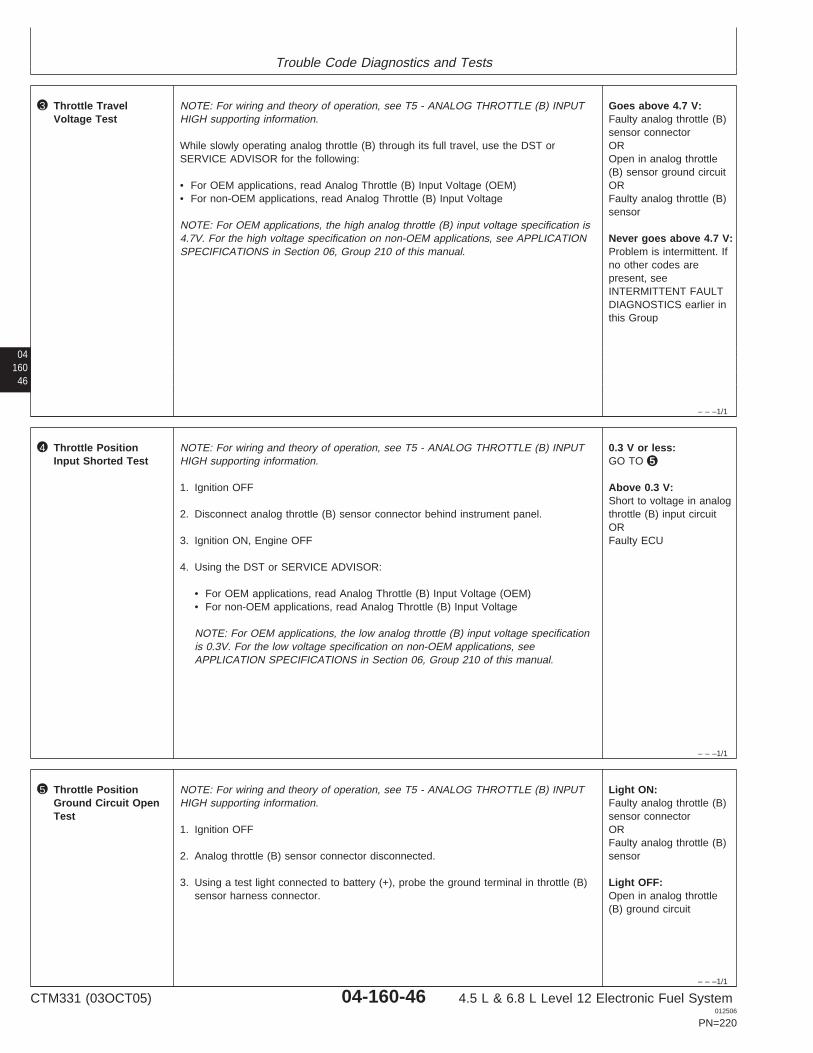
Trouble Code Diagnostics and Tests
04160
46
– – –1/1
3 Throttle TravelVoltage Test
NOTE: For wiring and theory of operation, see T5 - ANALOG THROTTLE (B) INPUTHIGH supporting information.
While slowly operating analog throttle (B) through its full travel, use the DST orSERVICE ADVISOR for the following:
• For OEM applications, read Analog Throttle (B) Input Voltage (OEM)• For non-OEM applications, read Analog Throttle (B) Input Voltage
NOTE: For OEM applications, the high analog throttle (B) input voltage specification is4.7V. For the high voltage specification on non-OEM applications, see APPLICATIONSPECIFICATIONS in Section 06, Group 210 of this manual.
Goes above 4.7 V:Faulty analog throttle (B)sensor connectorOROpen in analog throttle(B) sensor ground circuitORFaulty analog throttle (B)sensor
Never goes above 4.7 V:Problem is intermittent. Ifno other codes arepresent, seeINTERMITTENT FAULTDIAGNOSTICS earlier inthis Group
– – –1/1
4 Throttle PositionInput Shorted Test
NOTE: For wiring and theory of operation, see T5 - ANALOG THROTTLE (B) INPUTHIGH supporting information.
1. Ignition OFF
2. Disconnect analog throttle (B) sensor connector behind instrument panel.
3. Ignition ON, Engine OFF
4. Using the DST or SERVICE ADVISOR:
• For OEM applications, read Analog Throttle (B) Input Voltage (OEM)• For non-OEM applications, read Analog Throttle (B) Input Voltage
NOTE: For OEM applications, the low analog throttle (B) input voltage specificationis 0.3V. For the low voltage specification on non-OEM applications, seeAPPLICATION SPECIFICATIONS in Section 06, Group 210 of this manual.
0.3 V or less:GO TO 5
Above 0.3 V:Short to voltage in analogthrottle (B) input circuitORFaulty ECU
– – –1/1
5 Throttle PositionGround Circuit OpenTest
NOTE: For wiring and theory of operation, see T5 - ANALOG THROTTLE (B) INPUTHIGH supporting information.
1. Ignition OFF
2. Analog throttle (B) sensor connector disconnected.
3. Using a test light connected to battery (+), probe the ground terminal in throttle (B)sensor harness connector.
Light ON:Faulty analog throttle (B)sensor connectorORFaulty analog throttle (B)sensor
Light OFF:Open in analog throttle(B) ground circuit
CTM331 (03OCT05) 04-160-46 4.5 L & 6.8 L Level 12 Electronic Fuel System012506
PN=220

Trouble Code Diagnostics and Tests
0416047
CTM331 (03OCT05) 04-160-47 4.5 L & 6.8 L Level 12 Electronic Fuel System012506
PN=221
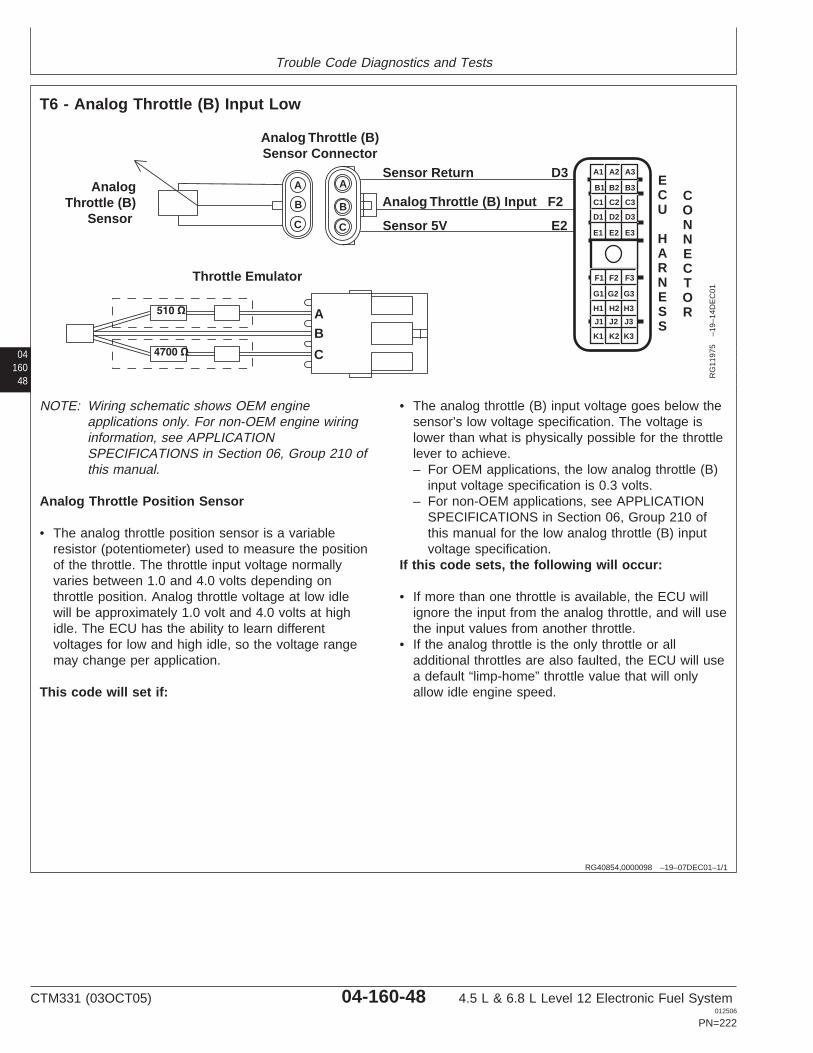
Trouble Code Diagnostics and Tests
04160
48
RG40854,0000098 –19–07DEC01–1/1
T6 - Analog Throttle (B) Input Low
Sensor Return D3
Analog Throttle (B) Input F2
Sensor 5V E2
Analog Throttle (B)Sensor Connector
Throttle Emulator
AnalogThrottle (B)
Sensor
A
A A
B B
C C
B
C
A1 A2 A3
B3
C3
D3
E3
B2
C2
D2
E2
B1
C1
D1
E1
F1 F2 F3
G3
H3
J3
K3
G2
H2
J2
K2
G1
H1
J1
K1
ECU
HARNESS
CONNECTOR
RG
1197
5–1
9–14
DE
C01
NOTE: Wiring schematic shows OEM engineapplications only. For non-OEM engine wiringinformation, see APPLICATIONSPECIFICATIONS in Section 06, Group 210 ofthis manual.
Analog Throttle Position Sensor
• The analog throttle position sensor is a variableresistor (potentiometer) used to measure the positionof the throttle. The throttle input voltage normallyvaries between 1.0 and 4.0 volts depending onthrottle position. Analog throttle voltage at low idlewill be approximately 1.0 volt and 4.0 volts at highidle. The ECU has the ability to learn differentvoltages for low and high idle, so the voltage rangemay change per application.
This code will set if:
• The analog throttle (B) input voltage goes below thesensor’s low voltage specification. The voltage islower than what is physically possible for the throttlelever to achieve.– For OEM applications, the low analog throttle (B)
input voltage specification is 0.3 volts.– For non-OEM applications, see APPLICATION
SPECIFICATIONS in Section 06, Group 210 ofthis manual for the low analog throttle (B) inputvoltage specification.
If this code sets, the following will occur:
• If more than one throttle is available, the ECU willignore the input from the analog throttle, and will usethe input values from another throttle.
• If the analog throttle is the only throttle or alladditional throttles are also faulted, the ECU will usea default “limp-home” throttle value that will onlyallow idle engine speed.
CTM331 (03OCT05) 04-160-48 4.5 L & 6.8 L Level 12 Electronic Fuel System012506
PN=222
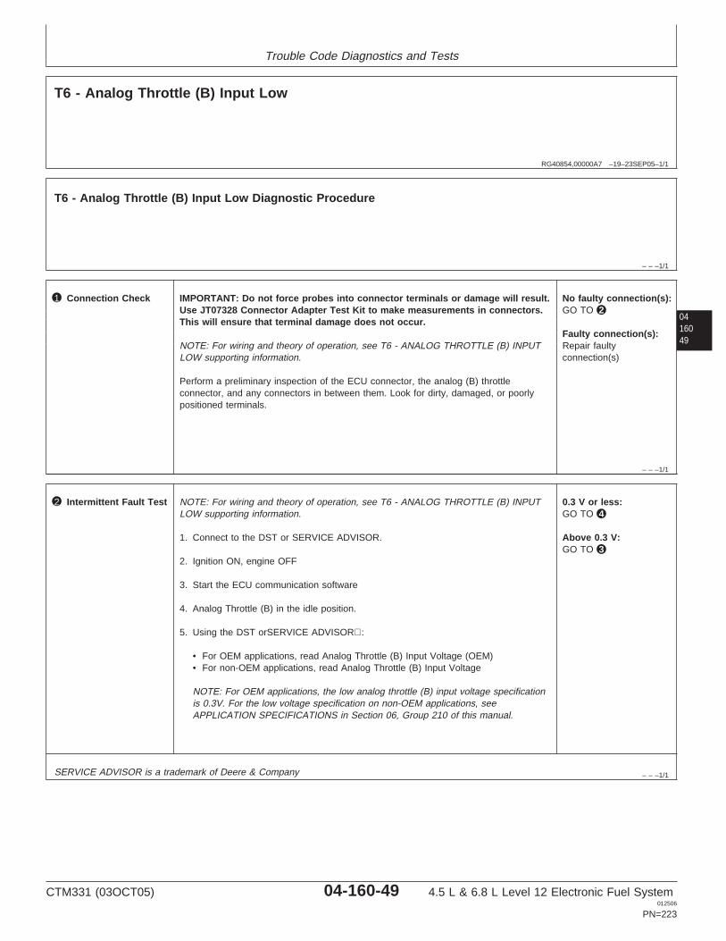
Trouble Code Diagnostics and Tests
RG40854,00000A7 –19–23SEP05–1/1
T6 - Analog Throttle (B) Input Low
– – –1/1
T6 - Analog Throttle (B) Input Low Diagnostic Procedure
0416049
– – –1/1
1 Connection Check IMPORTANT: Do not force probes into connector terminals or damage will result.Use JT07328 Connector Adapter Test Kit to make measurements in connectors.This will ensure that terminal damage does not occur.
NOTE: For wiring and theory of operation, see T6 - ANALOG THROTTLE (B) INPUTLOW supporting information.
Perform a preliminary inspection of the ECU connector, the analog (B) throttleconnector, and any connectors in between them. Look for dirty, damaged, or poorlypositioned terminals.
No faulty connection(s):GO TO 2
Faulty connection(s):Repair faultyconnection(s)
– – –1/1
2 Intermittent Fault Test NOTE: For wiring and theory of operation, see T6 - ANALOG THROTTLE (B) INPUTLOW supporting information.
1. Connect to the DST or SERVICE ADVISOR.
2. Ignition ON, engine OFF
3. Start the ECU communication software
4. Analog Throttle (B) in the idle position.
5. Using the DST orSERVICE ADVISOR:
• For OEM applications, read Analog Throttle (B) Input Voltage (OEM)• For non-OEM applications, read Analog Throttle (B) Input Voltage
NOTE: For OEM applications, the low analog throttle (B) input voltage specificationis 0.3V. For the low voltage specification on non-OEM applications, seeAPPLICATION SPECIFICATIONS in Section 06, Group 210 of this manual.
0.3 V or less:GO TO 4
Above 0.3 V:GO TO 3
SERVICE ADVISOR is a trademark of Deere & Company
CTM331 (03OCT05) 04-160-49 4.5 L & 6.8 L Level 12 Electronic Fuel System012506
PN=223
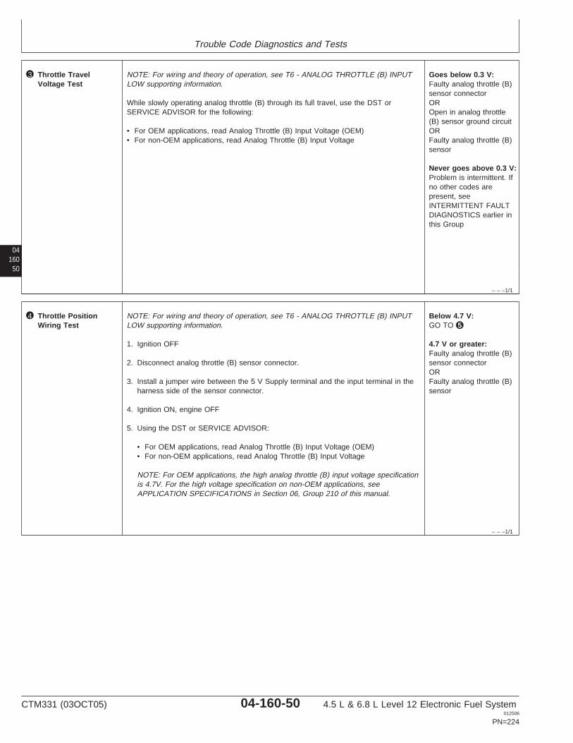
Trouble Code Diagnostics and Tests
04160
50
– – –1/1
3 Throttle TravelVoltage Test
NOTE: For wiring and theory of operation, see T6 - ANALOG THROTTLE (B) INPUTLOW supporting information.
While slowly operating analog throttle (B) through its full travel, use the DST orSERVICE ADVISOR for the following:
• For OEM applications, read Analog Throttle (B) Input Voltage (OEM)• For non-OEM applications, read Analog Throttle (B) Input Voltage
Goes below 0.3 V:Faulty analog throttle (B)sensor connectorOROpen in analog throttle(B) sensor ground circuitORFaulty analog throttle (B)sensor
Never goes above 0.3 V:Problem is intermittent. Ifno other codes arepresent, seeINTERMITTENT FAULTDIAGNOSTICS earlier inthis Group
– – –1/1
4 Throttle PositionWiring Test
NOTE: For wiring and theory of operation, see T6 - ANALOG THROTTLE (B) INPUTLOW supporting information.
1. Ignition OFF
2. Disconnect analog throttle (B) sensor connector.
3. Install a jumper wire between the 5 V Supply terminal and the input terminal in theharness side of the sensor connector.
4. Ignition ON, engine OFF
5. Using the DST or SERVICE ADVISOR:
• For OEM applications, read Analog Throttle (B) Input Voltage (OEM)• For non-OEM applications, read Analog Throttle (B) Input Voltage
NOTE: For OEM applications, the high analog throttle (B) input voltage specificationis 4.7V. For the high voltage specification on non-OEM applications, seeAPPLICATION SPECIFICATIONS in Section 06, Group 210 of this manual.
Below 4.7 V:GO TO 5
4.7 V or greater:Faulty analog throttle (B)sensor connectorORFaulty analog throttle (B)sensor
CTM331 (03OCT05) 04-160-50 4.5 L & 6.8 L Level 12 Electronic Fuel System012506
PN=224

Trouble Code Diagnostics and Tests
0416051
– – –1/1
5 Throttle Position 5 VSupply Test
NOTE: For wiring and theory of operation, see T6 - ANALOG THROTTLE (B) INPUTLOW supporting information.
1. Ignition OFF
2. Remove jumper wire.
3. Ignition ON, engine OFF
4. Using a multimeter, measure the voltage between the analog throttle (B) groundterminal and the 5 V Supply terminal in the sensor harness connector.
Between 4.0 V and 6.0V:Open in analog throttle(B) input circuitORShort to ground in analogthrottle (B) input circuitORFaulty ECU connectorORFaulty ECU
Below 4.0 V:Open in analog throttle(B) 5 V Supply circuitORShort to ground in analogthrottle (B) 5 V SupplycircuitORFaulty ECU connectorORFaulty ECU
CTM331 (03OCT05) 04-160-51 4.5 L & 6.8 L Level 12 Electronic Fuel System012506
PN=225

Trouble Code Diagnostics and Tests
04160
52
RG40854,0000096 –19–07DEC01–1/1
T7 - CAN Throttle Invalid
CAN Low
CAN High
CAN Shield
BA
C
DCEBA
Switched Voltage
CAN Terminator
Static Ground
DiagnosticConnector
DC
BJ
HG
F
E
B A A B
CC
A
F1
G1
A1 A2 A3
B3
C3
D3
E3
B2
C2
D2
E2
B1
C1
D1
E1
F1 F2 F3
G3
H3
J3
K3
G2
H2
J2
K2
G1
H1
J1
K1
ECU
HARNESS
CONNECTOR
RG
1197
2–1
9–14
DE
C01
CAN (Controller Area Network) Throttle
• CAN (Controller Area Network) throttle is informationsent to the ECU by another controller over CAN ofthe desired throttle position.
This code will set if:
• The ECU either does not receive throttle informationover CAN, or the information received is not valid.
If this code sets, the following will occur:
• If more than one throttle is available, the ECU willignore the input from the CAN throttle, and will usethe input values from another throttle.
• If the CAN throttle is the only throttle or all additionalthrottles are also faulted, the ECU will use a default“limp-home” throttle value that will only allow idleengine speed.
CTM331 (03OCT05) 04-160-52 4.5 L & 6.8 L Level 12 Electronic Fuel System012506
PN=226
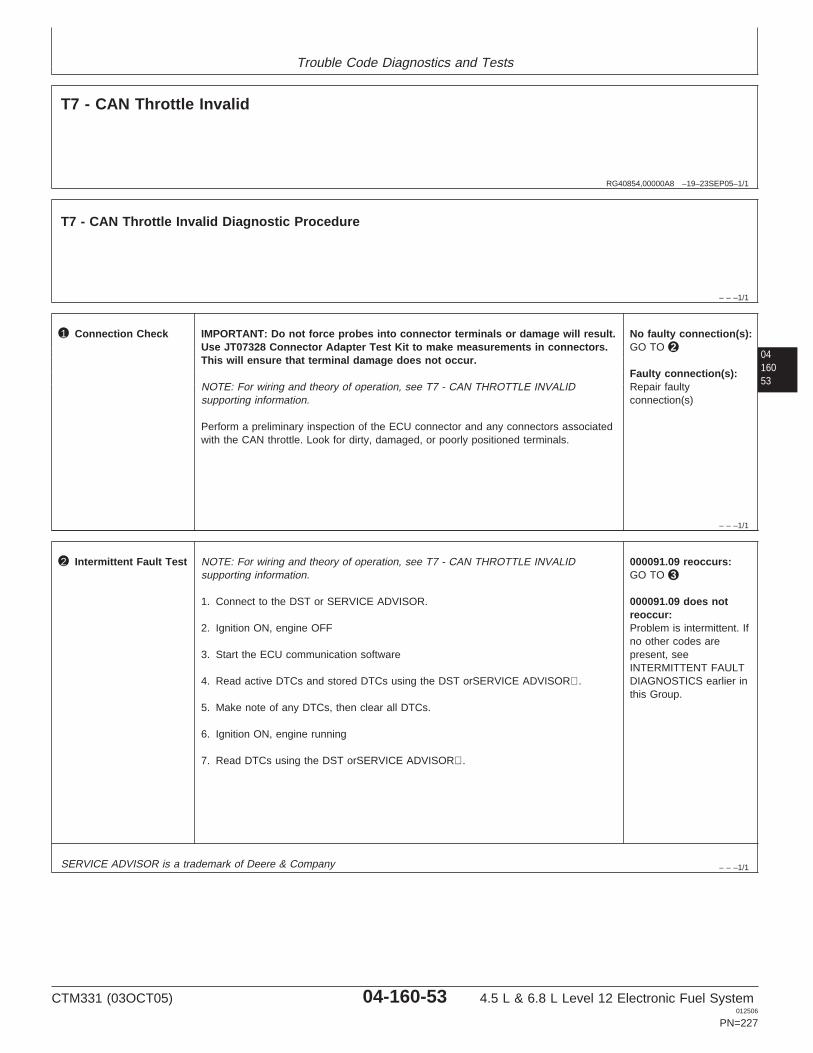
Trouble Code Diagnostics and Tests
RG40854,00000A8 –19–23SEP05–1/1
T7 - CAN Throttle Invalid
– – –1/1
T7 - CAN Throttle Invalid Diagnostic Procedure
0416053
– – –1/1
1 Connection Check IMPORTANT: Do not force probes into connector terminals or damage will result.Use JT07328 Connector Adapter Test Kit to make measurements in connectors.This will ensure that terminal damage does not occur.
NOTE: For wiring and theory of operation, see T7 - CAN THROTTLE INVALIDsupporting information.
Perform a preliminary inspection of the ECU connector and any connectors associatedwith the CAN throttle. Look for dirty, damaged, or poorly positioned terminals.
No faulty connection(s):GO TO 2
Faulty connection(s):Repair faultyconnection(s)
– – –1/1
2 Intermittent Fault Test NOTE: For wiring and theory of operation, see T7 - CAN THROTTLE INVALIDsupporting information.
1. Connect to the DST or SERVICE ADVISOR.
2. Ignition ON, engine OFF
3. Start the ECU communication software
4. Read active DTCs and stored DTCs using the DST orSERVICE ADVISOR.
5. Make note of any DTCs, then clear all DTCs.
6. Ignition ON, engine running
7. Read DTCs using the DST orSERVICE ADVISOR.
000091.09 reoccurs:GO TO 3
000091.09 does notreoccur:Problem is intermittent. Ifno other codes arepresent, seeINTERMITTENT FAULTDIAGNOSTICS earlier inthis Group.
SERVICE ADVISOR is a trademark of Deere & Company
CTM331 (03OCT05) 04-160-53 4.5 L & 6.8 L Level 12 Electronic Fuel System012506
PN=227
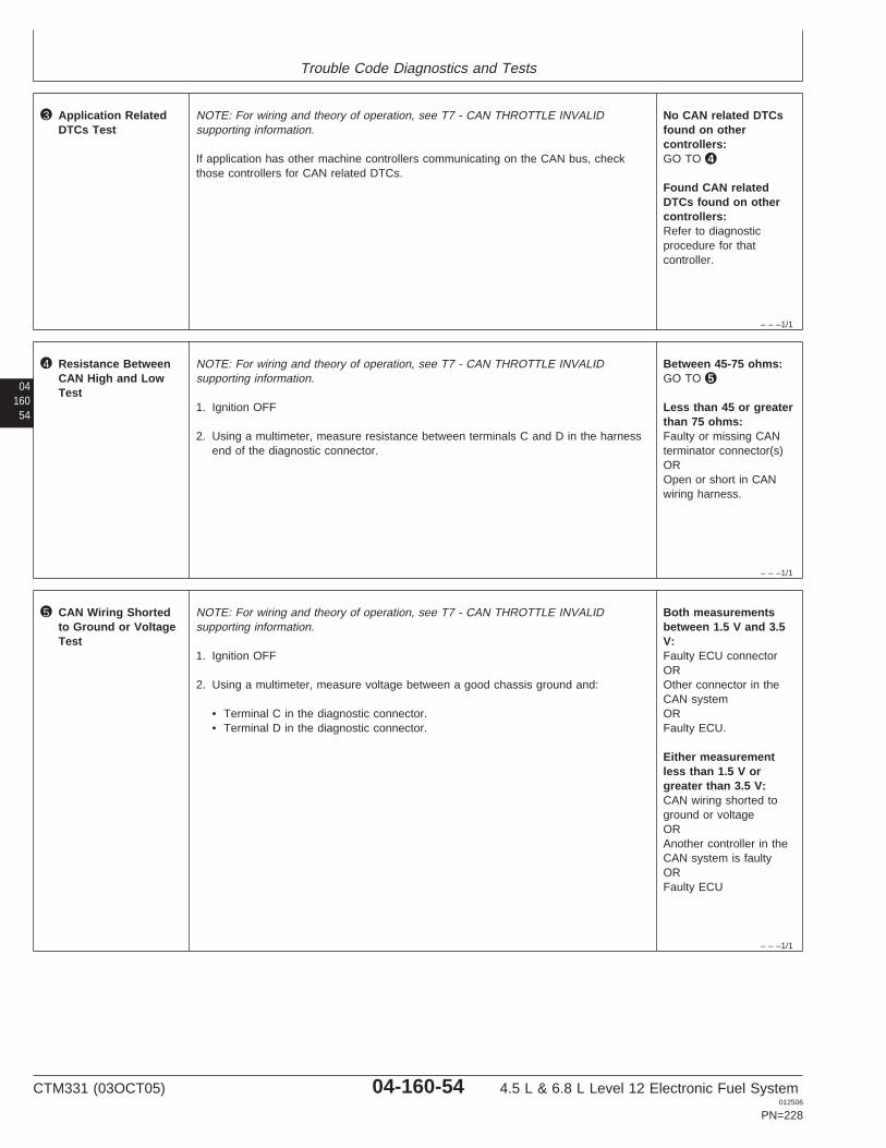
Trouble Code Diagnostics and Tests
– – –1/1
3 Application RelatedDTCs Test
NOTE: For wiring and theory of operation, see T7 - CAN THROTTLE INVALIDsupporting information.
If application has other machine controllers communicating on the CAN bus, checkthose controllers for CAN related DTCs.
No CAN related DTCsfound on othercontrollers:GO TO 4
Found CAN relatedDTCs found on othercontrollers:Refer to diagnosticprocedure for thatcontroller.
04160
54
– – –1/1
4 Resistance BetweenCAN High and LowTest
NOTE: For wiring and theory of operation, see T7 - CAN THROTTLE INVALIDsupporting information.
1. Ignition OFF
2. Using a multimeter, measure resistance between terminals C and D in the harnessend of the diagnostic connector.
Between 45-75 ohms:GO TO 5
Less than 45 or greaterthan 75 ohms:Faulty or missing CANterminator connector(s)OROpen or short in CANwiring harness.
– – –1/1
5 CAN Wiring Shortedto Ground or VoltageTest
NOTE: For wiring and theory of operation, see T7 - CAN THROTTLE INVALIDsupporting information.
1. Ignition OFF
2. Using a multimeter, measure voltage between a good chassis ground and:
• Terminal C in the diagnostic connector.• Terminal D in the diagnostic connector.
Both measurementsbetween 1.5 V and 3.5V:Faulty ECU connectorOROther connector in theCAN systemORFaulty ECU.
Either measurementless than 1.5 V orgreater than 3.5 V:CAN wiring shorted toground or voltageORAnother controller in theCAN system is faultyORFaulty ECU
CTM331 (03OCT05) 04-160-54 4.5 L & 6.8 L Level 12 Electronic Fuel System012506
PN=228

Trouble Code Diagnostics and Tests
0416055
CTM331 (03OCT05) 04-160-55 4.5 L & 6.8 L Level 12 Electronic Fuel System012506
PN=229

Trouble Code Diagnostics and Tests
04160
56
RG40854,0000094 –19–07DEC01–1/1
T11 - Excavator Throttle Reference Voltage High
A1 A2 A3
B3
C3
D3
E3
B2
C2
D2
E2
B1
C1
D1
E1
F1 F2 F3
G3
H3
J3
K3
G2
H2
J2
K2
G1
H1
J1
K1
ECU
HARNESS
CONNECTOR
Throttle Reference F3
Throttle Input B3
Throttle Ground C1
To Pumpand ValveController
RG
1197
7–1
9–14
DE
C01
Excavator Throttle
• The Excavator uses an analog throttle to measurethrottle position. This throttle is connected to thePump and Valve controller, which sends throttleinput information to the ECU through a dedicatedwire. Since the ECU and Pump and Valve controllerdo not share a common ground, a throttle voltagereference wire and a throttle ground wire accompanythe throttle input wire. The ECU calculates thedifferences in controller grounds in order todetermine the throttle request by the Pump andValve controller.
This code will set if:
• The excavator throttle reference voltage to the ECUexceeds 4.2 volts.
If this code sets, the following will occur:
• The ECU will default excavator reference throttlevoltage to 3.75 volts.
CTM331 (03OCT05) 04-160-56 4.5 L & 6.8 L Level 12 Electronic Fuel System012506
PN=230

Trouble Code Diagnostics and Tests
RG40854,00000A9 –19–23SEP05–1/1
T11 - Excavator Throttle Reference Voltage High
– – –1/1
T11 - Excavator Throttle Reference Voltage High Diagnostic Procedure
NOTE: This diagnostic procedure is only used to diagnose the Excavator Throttle.
0416057
– – –1/1
1 Connection Check IMPORTANT: Do not force probes into connector terminals or damage will result.Use JT07328 Connector Adapter Test Kit to make measurements in connectors.This will ensure that terminal damage does not occur.
NOTE: For wiring and theory of operation, see T11 - EXCAVATOR THROTTLEREFERENCE VOLTAGE HIGH supporting information.
Perform a preliminary inspection of the ECU connector, throttle sensor connector, andany connectors in between them. Look for dirty, damaged, or poorly positionedterminals.
No faulty connection(s):GO TO 2
Faulty connection(s):Repair faultyconnection(s)
– – –1/1
2 Intermittent Fault Test NOTE: For wiring and theory of operation, see T11 - EXCAVATOR THROTTLEREFERENCE VOLTAGE HIGH supporting information.
1. Connect to the DST or SERVICE ADVISOR.
2. Ignition ON, engine OFF
3. Start the ECU communication software
4. Read active DTCs and stored DTCs using the DST orSERVICE ADVISOR.
5. Make note of any DTCs, then clear all DTCs using the DST orSERVICEADVISOR.
NOTE: If DTCs 000029.03 or 000029.04 are active, follow those DTCs first.
6. Read DTCs using the DST orSERVICE ADVISOR.
• Ignition ON, engine OFF• Ignition ON, engine running
000028.03 reoccurswhen engine is off andrunning:GO TO 3
000028.03 reoccurs onlywhen engine is running:GO TO 4
000028.03 does notreoccur:Problem is intermittent. Ifno other codes arepresent, seeINTERMITTENT FAULTDIAGNOSTICS earlier inthis Group.
SERVICE ADVISOR is a trademark of Deere & Company
CTM331 (03OCT05) 04-160-57 4.5 L & 6.8 L Level 12 Electronic Fuel System012506
PN=231

Trouble Code Diagnostics and Tests
– – –1/1
3 Throttle ReferenceWire Test
NOTE: For wiring and theory of operation, see T11 - EXCAVATOR THROTTLEREFERENCE VOLTAGE HIGH supporting information.
1. Ignition OFF
2. Disconnect ECU connector.
3. Using a multimeter, measure voltage between terminal F3 in the harness end of theECU connector and the ground stud of the Pump and Valve controller.
3.95 V or less:GO TO 4
Greater than 3.95 V:Short to power in throttlereference wireORFaulty Pump and Valvecontroller connectorORFaulty Pump and Valvecontroller
04160
58
– – –1/1
4 Ground Test NOTE: For wiring and theory of operation, see T11 - EXCAVATOR THROTTLEREFERENCE VOLTAGE HIGH supporting information.
There is a difference between grounds of the ECU and Pump and Valve controller.Check for loose ground connections at each controller.
CTM331 (03OCT05) 04-160-58 4.5 L & 6.8 L Level 12 Electronic Fuel System012506
PN=232

Trouble Code Diagnostics and Tests
0416059
CTM331 (03OCT05) 04-160-59 4.5 L & 6.8 L Level 12 Electronic Fuel System012506
PN=233

Trouble Code Diagnostics and Tests
04160
60
RG40854,0000092 –19–07DEC01–1/1
T12 - Excavator Throttle Reference Voltage Low
A1 A2 A3
B3
C3
D3
E3
B2
C2
D2
E2
B1
C1
D1
E1
F1 F2 F3
G3
H3
J3
K3
G2
H2
J2
K2
G1
H1
J1
K1
ECU
HARNESS
CONNECTOR
Throttle Reference F3
Throttle Input B3
Throttle Ground C1
To Pumpand ValveController
RG
1197
7–1
9–14
DE
C01
Excavator Throttle
• The Excavator uses an analog throttle to measurethrottle position. This throttle is connected to thePump and Valve controller, which sends throttleinput information to the ECU through a dedicatedwire. Since the ECU and Pump and Valve controllerdo not share a common ground, a throttle voltagereference wire and a throttle ground wire accompanythe throttle input wire. The ECU calculates thedifferences in controller grounds in order todetermine the throttle request by the Pump andValve controller.
This code will set if:
• The excavator throttle reference voltage to the ECUgoes below 2.7 volts.
If this code sets, the following will occur:
• The ECU will default excavator reference throttlevoltage to 3.75 volts.
CTM331 (03OCT05) 04-160-60 4.5 L & 6.8 L Level 12 Electronic Fuel System012506
PN=234

Trouble Code Diagnostics and Tests
RG40854,0000091 –19–23SEP05–1/1
T12 - Excavator Throttle Reference Voltage Low
– – –1/1
T12 - Excavator Throttle Reference Voltage Low Diagnostic Procedure
NOTE: This diagnostic procedure is only used to diagnose the Excavator Throttle.
0416061
– – –1/1
1 Connection Check IMPORTANT: Do not force probes into connector terminals or damage will result.Use JT07328 Connector Adapter Test Kit to make measurements in connectors.This will ensure that terminal damage does not occur.
NOTE: For wiring and theory of operation, see T12 - EXCAVATOR THROTTLEREFERENCE VOLTAGE LOW supporting information.
Perform a preliminary inspection of the ECU connector, throttle sensor connector, andany connectors in between them. Look for dirty, damaged, or poorly positionedterminals.
No faulty connection(s):GO TO 2
Faulty connection(s):Repair faultyconnection(s)
– – –1/1
2 Intermittent Fault Test NOTE: For wiring and theory of operation, see T12 - EXCAVATOR THROTTLEREFERENCE VOLTAGE LOW supporting information.
1. Connect to the DST or SERVICE ADVISOR.
2. Ignition ON, engine OFF
3. Start the ECU communication software
4. Read active DTCs and stored DTCs using the DST orSERVICE ADVISOR.
5. Make note of any DTCs, then clear all DTCs.
NOTE: If DTCs 000029.03 or 000029.04 are active, follow those DTCs first.
6. Read DTCs using the DST orSERVICE ADVISOR.
• Ignition ON, engine OFF• Ignition ON, engine running
000028.04 reoccurswhen engine is off andrunning:GO TO 3
000028.04 reoccurs onlywhen engine is running:GO TO 4
000028.04 does notreoccur:Problem is intermittent. Ifno other codes arepresent, seeINTERMITTENT FAULTDIAGNOSTICS earlier inthis Group.
SERVICE ADVISOR is a trademark of Deere & Company
CTM331 (03OCT05) 04-160-61 4.5 L & 6.8 L Level 12 Electronic Fuel System012506
PN=235
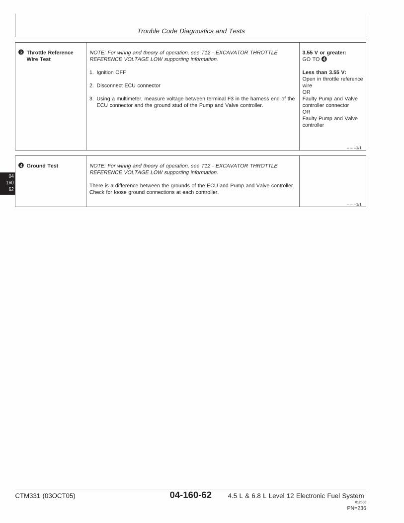
Trouble Code Diagnostics and Tests
– – –1/1
3 Throttle ReferenceWire Test
NOTE: For wiring and theory of operation, see T12 - EXCAVATOR THROTTLEREFERENCE VOLTAGE LOW supporting information.
1. Ignition OFF
2. Disconnect ECU connector
3. Using a multimeter, measure voltage between terminal F3 in the harness end of theECU connector and the ground stud of the Pump and Valve controller.
3.55 V or greater:GO TO 4
Less than 3.55 V:Open in throttle referencewireORFaulty Pump and Valvecontroller connectorORFaulty Pump and Valvecontroller
04160
62
– – –1/1
4 Ground Test NOTE: For wiring and theory of operation, see T12 - EXCAVATOR THROTTLEREFERENCE VOLTAGE LOW supporting information.
There is a difference between the grounds of the ECU and Pump and Valve controller.Check for loose ground connections at each controller.
CTM331 (03OCT05) 04-160-62 4.5 L & 6.8 L Level 12 Electronic Fuel System012506
PN=236

Trouble Code Diagnostics and Tests
0416063
CTM331 (03OCT05) 04-160-63 4.5 L & 6.8 L Level 12 Electronic Fuel System012506
PN=237

Trouble Code Diagnostics and Tests
04160
64
RG40854,0000090 –19–07DEC01–1/1
T13 - Excavator Throttle Ground Voltage High
A1 A2 A3
B3
C3
D3
E3
B2
C2
D2
E2
B1
C1
D1
E1
F1 F2 F3
G3
H3
J3
K3
G2
H2
J2
K2
G1
H1
J1
K1
ECU
HARNESS
CONNECTOR
Throttle Reference F3
Throttle Input B3
Throttle Ground C1
To Pumpand ValveController
RG
1197
7–1
9–14
DE
C01
Excavator Throttle
• The Excavator uses an analog throttle to measurethrottle position. This throttle is connected to thePump and Valve controller, which sends throttleinput information to the ECU through a dedicatedwire. Since the ECU and Pump and Valve controllerdo not share a common ground, a throttle voltagereference wire and a throttle ground wire accompanythe throttle input wire. The ECU calculates thedifferences in controller grounds in order todetermine the throttle request by the Pump andValve controller.
This code will set if:
• The excavator throttle ground voltage to the ECUexceeds 3.0 volts.
If this code sets, the following will occur:
• The ECU will default excavator throttle groundvoltage to 0 volts.
CTM331 (03OCT05) 04-160-64 4.5 L & 6.8 L Level 12 Electronic Fuel System012506
PN=238
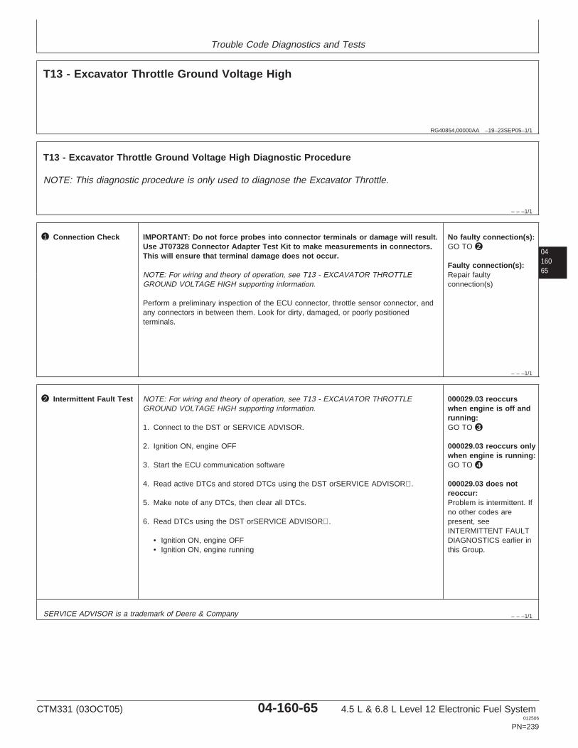
Trouble Code Diagnostics and Tests
RG40854,00000AA –19–23SEP05–1/1
T13 - Excavator Throttle Ground Voltage High
– – –1/1
T13 - Excavator Throttle Ground Voltage High Diagnostic Procedure
NOTE: This diagnostic procedure is only used to diagnose the Excavator Throttle.
0416065
– – –1/1
1 Connection Check IMPORTANT: Do not force probes into connector terminals or damage will result.Use JT07328 Connector Adapter Test Kit to make measurements in connectors.This will ensure that terminal damage does not occur.
NOTE: For wiring and theory of operation, see T13 - EXCAVATOR THROTTLEGROUND VOLTAGE HIGH supporting information.
Perform a preliminary inspection of the ECU connector, throttle sensor connector, andany connectors in between them. Look for dirty, damaged, or poorly positionedterminals.
No faulty connection(s):GO TO 2
Faulty connection(s):Repair faultyconnection(s)
– – –1/1
2 Intermittent Fault Test NOTE: For wiring and theory of operation, see T13 - EXCAVATOR THROTTLEGROUND VOLTAGE HIGH supporting information.
1. Connect to the DST or SERVICE ADVISOR.
2. Ignition ON, engine OFF
3. Start the ECU communication software
4. Read active DTCs and stored DTCs using the DST orSERVICE ADVISOR.
5. Make note of any DTCs, then clear all DTCs.
6. Read DTCs using the DST orSERVICE ADVISOR.
• Ignition ON, engine OFF• Ignition ON, engine running
000029.03 reoccurswhen engine is off andrunning:GO TO 3
000029.03 reoccurs onlywhen engine is running:GO TO 4
000029.03 does notreoccur:Problem is intermittent. Ifno other codes arepresent, seeINTERMITTENT FAULTDIAGNOSTICS earlier inthis Group.
SERVICE ADVISOR is a trademark of Deere & Company
CTM331 (03OCT05) 04-160-65 4.5 L & 6.8 L Level 12 Electronic Fuel System012506
PN=239
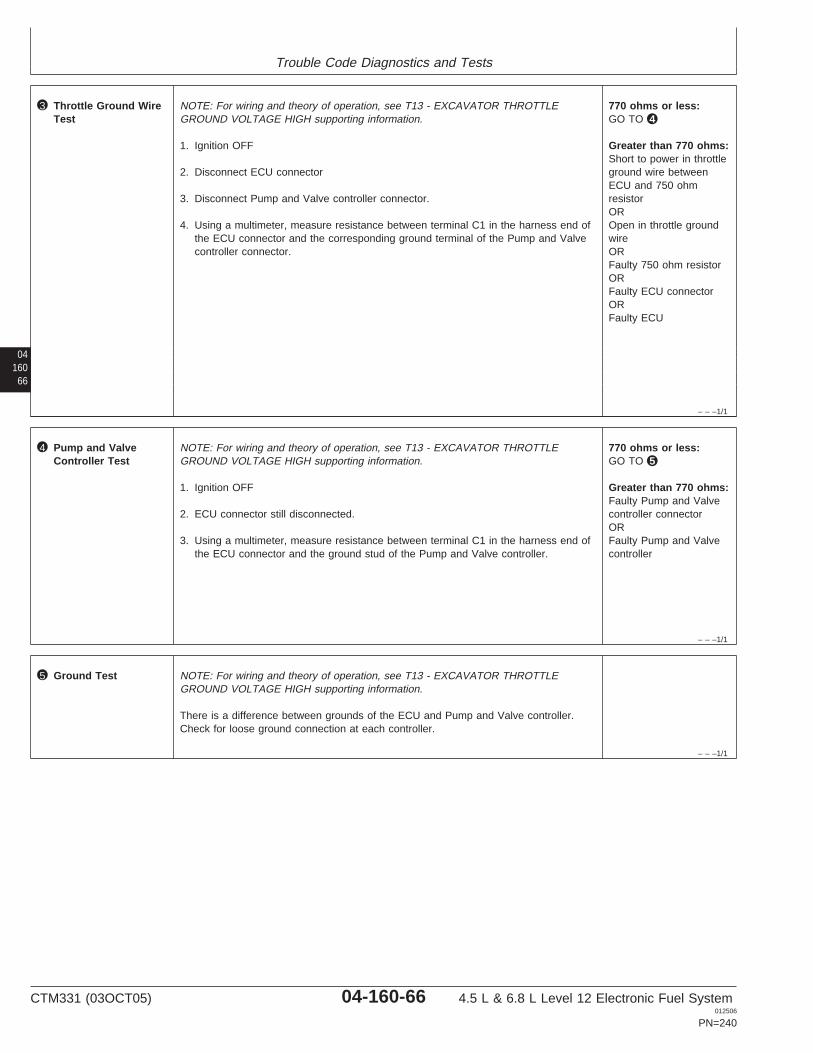
Trouble Code Diagnostics and Tests
04160
66
– – –1/1
3 Throttle Ground WireTest
NOTE: For wiring and theory of operation, see T13 - EXCAVATOR THROTTLEGROUND VOLTAGE HIGH supporting information.
1. Ignition OFF
2. Disconnect ECU connector
3. Disconnect Pump and Valve controller connector.
4. Using a multimeter, measure resistance between terminal C1 in the harness end ofthe ECU connector and the corresponding ground terminal of the Pump and Valvecontroller connector.
770 ohms or less:GO TO 4
Greater than 770 ohms:Short to power in throttleground wire betweenECU and 750 ohmresistorOROpen in throttle groundwireORFaulty 750 ohm resistorORFaulty ECU connectorORFaulty ECU
– – –1/1
4 Pump and ValveController Test
NOTE: For wiring and theory of operation, see T13 - EXCAVATOR THROTTLEGROUND VOLTAGE HIGH supporting information.
1. Ignition OFF
2. ECU connector still disconnected.
3. Using a multimeter, measure resistance between terminal C1 in the harness end ofthe ECU connector and the ground stud of the Pump and Valve controller.
770 ohms or less:GO TO 5
Greater than 770 ohms:Faulty Pump and Valvecontroller connectorORFaulty Pump and Valvecontroller
– – –1/1
5 Ground Test NOTE: For wiring and theory of operation, see T13 - EXCAVATOR THROTTLEGROUND VOLTAGE HIGH supporting information.
There is a difference between grounds of the ECU and Pump and Valve controller.Check for loose ground connection at each controller.
CTM331 (03OCT05) 04-160-66 4.5 L & 6.8 L Level 12 Electronic Fuel System012506
PN=240

Trouble Code Diagnostics and Tests
0416067
CTM331 (03OCT05) 04-160-67 4.5 L & 6.8 L Level 12 Electronic Fuel System012506
PN=241
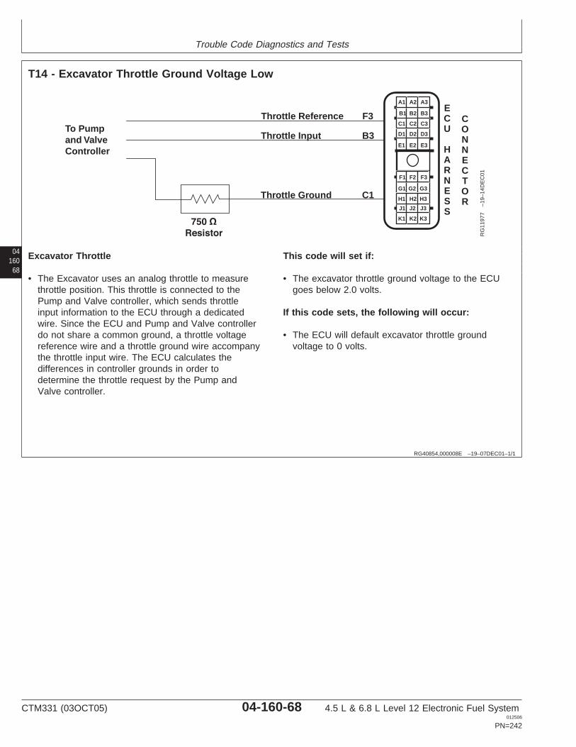
Trouble Code Diagnostics and Tests
04160
68
RG40854,000008E –19–07DEC01–1/1
T14 - Excavator Throttle Ground Voltage Low
A1 A2 A3
B3
C3
D3
E3
B2
C2
D2
E2
B1
C1
D1
E1
F1 F2 F3
G3
H3
J3
K3
G2
H2
J2
K2
G1
H1
J1
K1
ECU
HARNESS
CONNECTOR
Throttle Reference F3
Throttle Input B3
Throttle Ground C1
To Pumpand ValveController
RG
1197
7–1
9–14
DE
C01
Excavator Throttle
• The Excavator uses an analog throttle to measurethrottle position. This throttle is connected to thePump and Valve controller, which sends throttleinput information to the ECU through a dedicatedwire. Since the ECU and Pump and Valve controllerdo not share a common ground, a throttle voltagereference wire and a throttle ground wire accompanythe throttle input wire. The ECU calculates thedifferences in controller grounds in order todetermine the throttle request by the Pump andValve controller.
This code will set if:
• The excavator throttle ground voltage to the ECUgoes below 2.0 volts.
If this code sets, the following will occur:
• The ECU will default excavator throttle groundvoltage to 0 volts.
CTM331 (03OCT05) 04-160-68 4.5 L & 6.8 L Level 12 Electronic Fuel System012506
PN=242

Trouble Code Diagnostics and Tests
RG40854,00000AB –19–23SEP05–1/1
T14 - Excavator Throttle Ground Voltage Low
– – –1/1
T14 - Excavator Throttle Ground Voltage Low Diagnostic Procedure
NOTE: This diagnostic procedure is only used to diagnose the Excavator Throttle.
0416069
– – –1/1
1 Connection Check IMPORTANT: Do not force probes into connector terminals or damage will result.Use JT07328 Connector Adapter Test Kit to make measurements in connectors.This will ensure that terminal damage does not occur.
NOTE: For wiring and theory of operation, see T14 - EXCAVATOR THROTTLEGROUND VOLTAGE LOW supporting information.
Perform a preliminary inspection of the ECU connector, throttle sensor connector, andany connectors in between them. Look for dirty, damaged, or poorly positionedterminals.
No faulty connection(s):GO TO 2
Faulty connection(s):Repair faultyconnection(s)
– – –1/1
2 Intermittent Fault Test NOTE: For wiring and theory of operation, see T14 - EXCAVATOR THROTTLEGROUND VOLTAGE LOW supporting information.
1. Connect to the DST or SERVICE ADVISOR.
2. Ignition ON, engine OFF
3. Start the ECU communication software
4. Read active DTCs and stored DTCs using the DST orSERVICE ADVISOR.
5. Make note of any DTCs, then clear all DTCs.
6. Read DTCs using the DST orSERVICE ADVISOR.
• Ignition ON, engine OFF• Ignition ON, engine running
000029.04 reoccurswhen engine is off andrunning:GO TO 3
000029.04 reoccurs onlywhen engine is running:GO TO 4
000029.04 does notreoccur:Problem is intermittent. Ifno other codes arepresent, seeINTERMITTENT FAULTDIAGNOSTICS earlier inthis Group.
SERVICE ADVISOR is a trademark of Deere & Company
CTM331 (03OCT05) 04-160-69 4.5 L & 6.8 L Level 12 Electronic Fuel System012506
PN=243
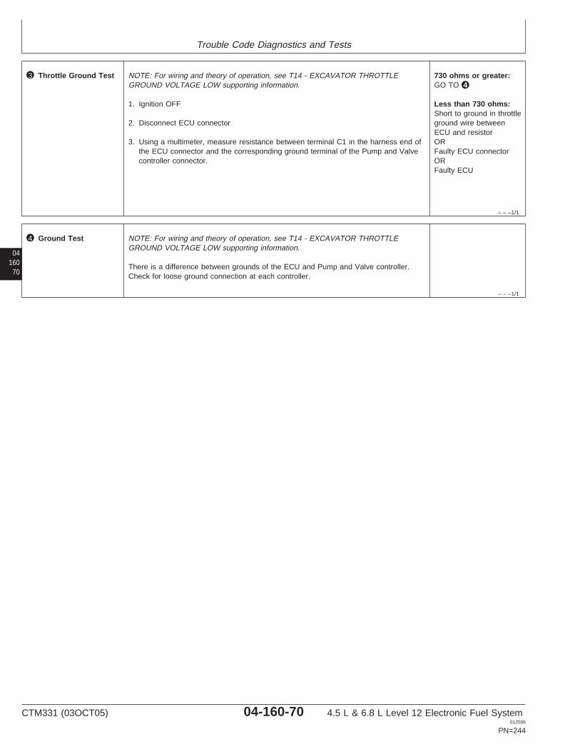
Trouble Code Diagnostics and Tests
– – –1/1
3 Throttle Ground Test NOTE: For wiring and theory of operation, see T14 - EXCAVATOR THROTTLEGROUND VOLTAGE LOW supporting information.
1. Ignition OFF
2. Disconnect ECU connector
3. Using a multimeter, measure resistance between terminal C1 in the harness end ofthe ECU connector and the corresponding ground terminal of the Pump and Valvecontroller connector.
730 ohms or greater:GO TO 4
Less than 730 ohms:Short to ground in throttleground wire betweenECU and resistorORFaulty ECU connectorORFaulty ECU
04160
70
– – –1/1
4 Ground Test NOTE: For wiring and theory of operation, see T14 - EXCAVATOR THROTTLEGROUND VOLTAGE LOW supporting information.
There is a difference between grounds of the ECU and Pump and Valve controller.Check for loose ground connection at each controller.
CTM331 (03OCT05) 04-160-70 4.5 L & 6.8 L Level 12 Electronic Fuel System012506
PN=244

Trouble Code Diagnostics and Tests
0416071
CTM331 (03OCT05) 04-160-71 4.5 L & 6.8 L Level 12 Electronic Fuel System012506
PN=245
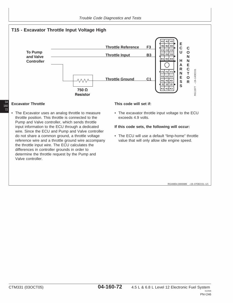
Trouble Code Diagnostics and Tests
04160
72
RG40854,0000089 –19–07DEC01–1/1
T15 - Excavator Throttle Input Voltage High
A1 A2 A3
B3
C3
D3
E3
B2
C2
D2
E2
B1
C1
D1
E1
F1 F2 F3
G3
H3
J3
K3
G2
H2
J2
K2
G1
H1
J1
K1
ECU
HARNESS
CONNECTOR
Throttle Reference F3
Throttle Input B3
Throttle Ground C1
To Pumpand ValveController
RG
1197
7–1
9–14
DE
C01
Excavator Throttle
• The Excavator uses an analog throttle to measurethrottle position. This throttle is connected to thePump and Valve controller, which sends throttleinput information to the ECU through a dedicatedwire. Since the ECU and Pump and Valve controllerdo not share a common ground, a throttle voltagereference wire and a throttle ground wire accompanythe throttle input wire. The ECU calculates thedifferences in controller grounds in order todetermine the throttle request by the Pump andValve controller.
This code will set if:
• The excavator throttle input voltage to the ECUexceeds 4.9 volts.
If this code sets, the following will occur:
• The ECU will use a default “limp-home” throttlevalue that will only allow idle engine speed.
CTM331 (03OCT05) 04-160-72 4.5 L & 6.8 L Level 12 Electronic Fuel System012506
PN=246
Trouble Code Diagnostics and Tests
RG40854,00000AC –19–23SEP05–1/1
T15 - Excavator Throttle Input Voltage High
– – –1/1
T15 - Excavator Throttle Input Voltage High Diagnostic Procedure
NOTE: This diagnostic procedure is only used to diagnose the Excavator Throttle.
0416073
– – –1/1
1 Connection Check IMPORTANT: Do not force probes into connector terminals or damage will result.Use JT07328 Connector Adapter Test Kit to make measurements in connectors.This will ensure that terminal damage does not occur.
NOTE: For wiring and theory of operation, see T15 - EXCAVATOR THROTTLE INPUTVOLTAGE HIGH supporting information.
Perform a preliminary inspection of the ECU connector, throttle sensor connector, andany connectors in between them. Look for dirty, damaged, or poorly positionedterminals.
No faulty connection(s):GO TO 2
Faulty connection(s):Repair faultyconnection(s)
– – –1/1
2 Intermittent Fault Test NOTE: For wiring and theory of operation, see T15 - EXCAVATOR THROTTLE INPUTVOLTAGE HIGH supporting information.
1. Connect to the DST or SERVICE ADVISOR.
2. Ignition ON, engine OFF
3. Start the ECU communication software
4. Read active DTCs and stored DTCs using the DST orSERVICE ADVISOR.
5. Make note of any DTCs, then clear all DTCs.
NOTE: If DTCs 000029.03 or 000029.04 are active, follow those DTCs first.
6. Read DTCs using the DST orSERVICE ADVISOR.
• Ignition ON, engine OFF• Ignition ON, engine running
000091.03 reoccurswhen engine is off andrunning:GO TO 3
000091.03 reoccurs onlywhen engine is running:GO TO 4
000091.03 does notreoccur:Problem is intermittent. Ifno other codes arepresent, seeINTERMITTENT FAULTDIAGNOSTICS earlier inthis Group.
SERVICE ADVISOR is a trademark of Deere & Company
CTM331 (03OCT05) 04-160-73 4.5 L & 6.8 L Level 12 Electronic Fuel System012506
PN=247

Trouble Code Diagnostics and Tests
– – –1/1
3 Throttle Signal WireTest
NOTE: For wiring and theory of operation, see T15 - EXCAVATOR THROTTLE INPUTVOLTAGE HIGH supporting information.
1. Ignition OFF
2. Disconnect ECU connector
3. Using a multimeter, measure voltage between terminal B3 in the harness end of theECU connector and the ground pin of the Pump and Valve controller.
4.0 V or less:GO TO 4
Greater than 4.0 V:Short to power in throttlesignal wireORFaulty Pump and Valvecontroller connectorORFaulty Pump and Valvecontroller
04160
74
– – –1/1
4 Ground Test NOTE: For wiring and theory of operation, see T15 - EXCAVATOR THROTTLE INPUTVOLTAGE HIGH supporting information.
There is a difference between grounds of the ECU and Pump and Valve controller.Check for loose ground connection at each controller.
CTM331 (03OCT05) 04-160-74 4.5 L & 6.8 L Level 12 Electronic Fuel System012506
PN=248
Trouble Code Diagnostics and Tests
0416075
CTM331 (03OCT05) 04-160-75 4.5 L & 6.8 L Level 12 Electronic Fuel System012506
PN=249
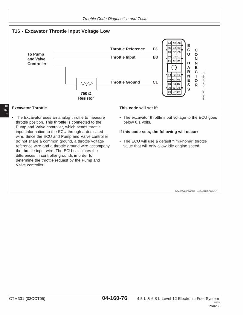
Trouble Code Diagnostics and Tests
04160
76
RG40854,000008B –19–07DEC01–1/1
T16 - Excavator Throttle Input Voltage Low
A1 A2 A3
B3
C3
D3
E3
B2
C2
D2
E2
B1
C1
D1
E1
F1 F2 F3
G3
H3
J3
K3
G2
H2
J2
K2
G1
H1
J1
K1
ECU
HARNESS
CONNECTOR
Throttle Reference F3
Throttle Input B3
Throttle Ground C1
To Pumpand ValveController
RG
1197
7–1
9–14
DE
C01
Excavator Throttle
• The Excavator uses an analog throttle to measurethrottle position. This throttle is connected to thePump and Valve controller, which sends throttleinput information to the ECU through a dedicatedwire. Since the ECU and Pump and Valve controllerdo not share a common ground, a throttle voltagereference wire and a throttle ground wire accompanythe throttle input wire. The ECU calculates thedifferences in controller grounds in order todetermine the throttle request by the Pump andValve controller.
This code will set if:
• The excavator throttle input voltage to the ECU goesbelow 0.1 volts.
If this code sets, the following will occur:
• The ECU will use a default “limp-home” throttlevalue that will only allow idle engine speed.
CTM331 (03OCT05) 04-160-76 4.5 L & 6.8 L Level 12 Electronic Fuel System012506
PN=250
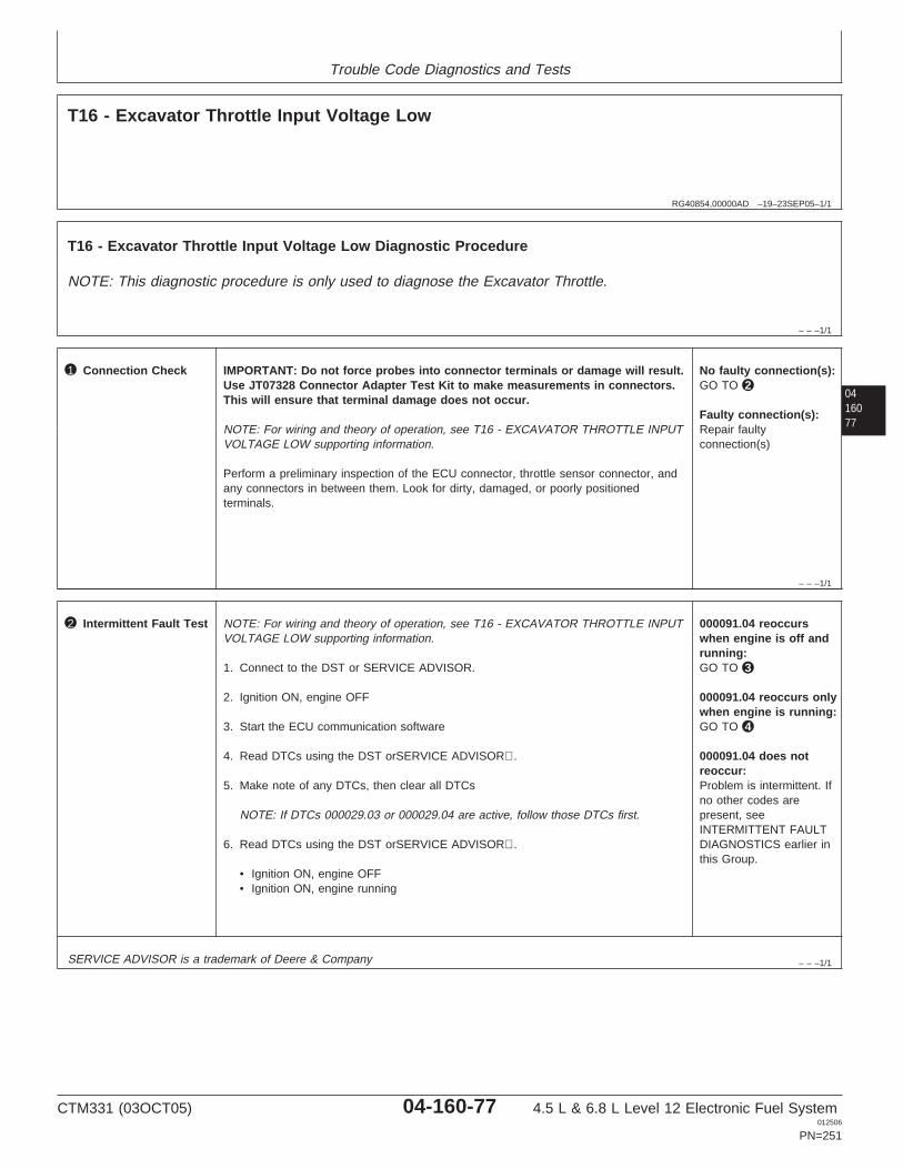
Trouble Code Diagnostics and Tests
RG40854,00000AD –19–23SEP05–1/1
T16 - Excavator Throttle Input Voltage Low
– – –1/1
T16 - Excavator Throttle Input Voltage Low Diagnostic Procedure
NOTE: This diagnostic procedure is only used to diagnose the Excavator Throttle.
0416077
– – –1/1
1 Connection Check IMPORTANT: Do not force probes into connector terminals or damage will result.Use JT07328 Connector Adapter Test Kit to make measurements in connectors.This will ensure that terminal damage does not occur.
NOTE: For wiring and theory of operation, see T16 - EXCAVATOR THROTTLE INPUTVOLTAGE LOW supporting information.
Perform a preliminary inspection of the ECU connector, throttle sensor connector, andany connectors in between them. Look for dirty, damaged, or poorly positionedterminals.
No faulty connection(s):GO TO 2
Faulty connection(s):Repair faultyconnection(s)
– – –1/1
2 Intermittent Fault Test NOTE: For wiring and theory of operation, see T16 - EXCAVATOR THROTTLE INPUTVOLTAGE LOW supporting information.
1. Connect to the DST or SERVICE ADVISOR.
2. Ignition ON, engine OFF
3. Start the ECU communication software
4. Read DTCs using the DST orSERVICE ADVISOR.
5. Make note of any DTCs, then clear all DTCs
NOTE: If DTCs 000029.03 or 000029.04 are active, follow those DTCs first.
6. Read DTCs using the DST orSERVICE ADVISOR.
• Ignition ON, engine OFF• Ignition ON, engine running
000091.04 reoccurswhen engine is off andrunning:GO TO 3
000091.04 reoccurs onlywhen engine is running:GO TO 4
000091.04 does notreoccur:Problem is intermittent. Ifno other codes arepresent, seeINTERMITTENT FAULTDIAGNOSTICS earlier inthis Group.
SERVICE ADVISOR is a trademark of Deere & Company
CTM331 (03OCT05) 04-160-77 4.5 L & 6.8 L Level 12 Electronic Fuel System012506
PN=251
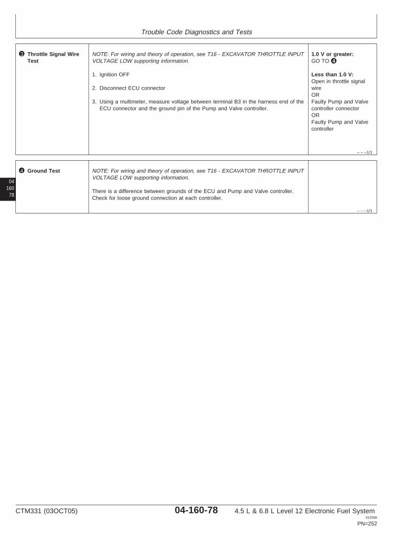
Trouble Code Diagnostics and Tests
– – –1/1
3 Throttle Signal WireTest
NOTE: For wiring and theory of operation, see T16 - EXCAVATOR THROTTLE INPUTVOLTAGE LOW supporting information.
1. Ignition OFF
2. Disconnect ECU connector
3. Using a multimeter, measure voltage between terminal B3 in the harness end of theECU connector and the ground pin of the Pump and Valve controller.
1.0 V or greater:GO TO 4
Less than 1.0 V:Open in throttle signalwireORFaulty Pump and Valvecontroller connectorORFaulty Pump and Valvecontroller
04160
78
– – –1/1
4 Ground Test NOTE: For wiring and theory of operation, see T16 - EXCAVATOR THROTTLE INPUTVOLTAGE LOW supporting information.
There is a difference between grounds of the ECU and Pump and Valve controller.Check for loose ground connection at each controller.
CTM331 (03OCT05) 04-160-78 4.5 L & 6.8 L Level 12 Electronic Fuel System012506
PN=252

Trouble Code Diagnostics and Tests
0416079
CTM331 (03OCT05) 04-160-79 4.5 L & 6.8 L Level 12 Electronic Fuel System012506
PN=253
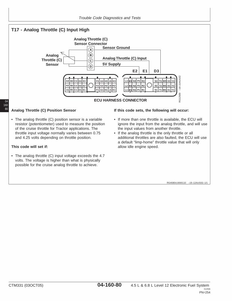
Trouble Code Diagnostics and Tests
04160
80
RG40854,0000110 –19–12AUG02–1/1
T17 - Analog Throttle (C) Input High
Y1
Y2
Y3X3W3T3S3
X2W2T2S2
X1W1T1S1R1
R2
R3P3N3M3L3
P2N2M2L2
P1N1M1L1A1
A2
A3 B3 C3 D3 E3
B2 C2 D2 E2
B1 C1 D1 E1 F1
F2
F3 G3 H3 J3 K3
G2 H2 J2 K2
G1 H1 J1 K1
ECU HARNESS CONNECTOR
Analog Throttle (C)Sensor Connector
Sensor Ground
5V Supply
Analog Throttle (C) InputAnalog
Throttle (C) Sensor
A
B
C
D
E2 D3E1
RG
1258
9–1
9–22
AU
G02
Analog Throttle (C) Position Sensor
• The analog throttle (C) position sensor is a variableresistor (potentiometer) used to measure the positionof the cruise throttle for Tractor applications. Thethrottle input voltage normally varies between 0.75and 4.25 volts depending on throttle position.
This code will set if:
• The analog throttle (C) input voltage exceeds the 4.7volts. The voltage is higher than what is physicallypossible for the cruise analog throttle to achieve.
If this code sets, the following will occur:
• If more than one throttle is available, the ECU willignore the input from the analog throttle, and will usethe input values from another throttle.
• If the analog throttle is the only throttle or alladditional throttles are also faulted, the ECU will usea default “limp-home” throttle value that will onlyallow idle engine speed.
CTM331 (03OCT05) 04-160-80 4.5 L & 6.8 L Level 12 Electronic Fuel System012506
PN=254
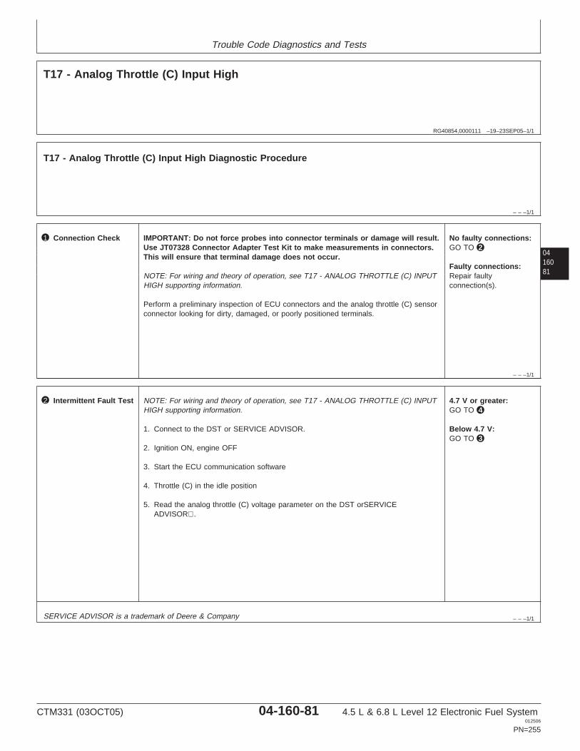
Trouble Code Diagnostics and Tests
RG40854,0000111 –19–23SEP05–1/1
T17 - Analog Throttle (C) Input High
– – –1/1
T17 - Analog Throttle (C) Input High Diagnostic Procedure
0416081
– – –1/1
1 Connection Check IMPORTANT: Do not force probes into connector terminals or damage will result.Use JT07328 Connector Adapter Test Kit to make measurements in connectors.This will ensure that terminal damage does not occur.
NOTE: For wiring and theory of operation, see T17 - ANALOG THROTTLE (C) INPUTHIGH supporting information.
Perform a preliminary inspection of ECU connectors and the analog throttle (C) sensorconnector looking for dirty, damaged, or poorly positioned terminals.
No faulty connections:GO TO 2
Faulty connections:Repair faultyconnection(s).
– – –1/1
2 Intermittent Fault Test NOTE: For wiring and theory of operation, see T17 - ANALOG THROTTLE (C) INPUTHIGH supporting information.
1. Connect to the DST or SERVICE ADVISOR.
2. Ignition ON, engine OFF
3. Start the ECU communication software
4. Throttle (C) in the idle position
5. Read the analog throttle (C) voltage parameter on the DST orSERVICEADVISOR.
4.7 V or greater:GO TO 4
Below 4.7 V:GO TO 3
SERVICE ADVISOR is a trademark of Deere & Company
CTM331 (03OCT05) 04-160-81 4.5 L & 6.8 L Level 12 Electronic Fuel System012506
PN=255
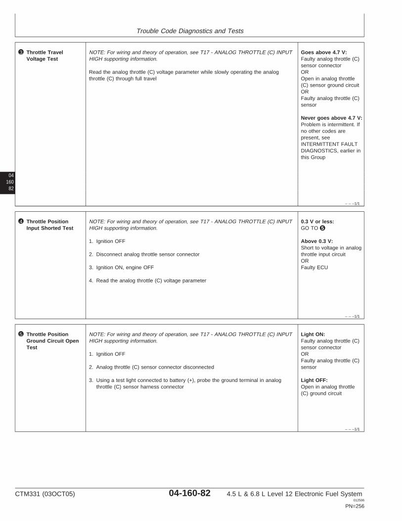
Trouble Code Diagnostics and Tests
04160
82
– – –1/1
3 Throttle TravelVoltage Test
NOTE: For wiring and theory of operation, see T17 - ANALOG THROTTLE (C) INPUTHIGH supporting information.
Read the analog throttle (C) voltage parameter while slowly operating the analogthrottle (C) through full travel
Goes above 4.7 V:Faulty analog throttle (C)sensor connectorOROpen in analog throttle(C) sensor ground circuitORFaulty analog throttle (C)sensor
Never goes above 4.7 V:Problem is intermittent. Ifno other codes arepresent, seeINTERMITTENT FAULTDIAGNOSTICS, earlier inthis Group
– – –1/1
4 Throttle PositionInput Shorted Test
NOTE: For wiring and theory of operation, see T17 - ANALOG THROTTLE (C) INPUTHIGH supporting information.
1. Ignition OFF
2. Disconnect analog throttle sensor connector
3. Ignition ON, engine OFF
4. Read the analog throttle (C) voltage parameter
0.3 V or less:GO TO 5
Above 0.3 V:Short to voltage in analogthrottle input circuitORFaulty ECU
– – –1/1
5 Throttle PositionGround Circuit OpenTest
NOTE: For wiring and theory of operation, see T17 - ANALOG THROTTLE (C) INPUTHIGH supporting information.
1. Ignition OFF
2. Analog throttle (C) sensor connector disconnected
3. Using a test light connected to battery (+), probe the ground terminal in analogthrottle (C) sensor harness connector
Light ON:Faulty analog throttle (C)sensor connectorORFaulty analog throttle (C)sensor
Light OFF:Open in analog throttle(C) ground circuit
CTM331 (03OCT05) 04-160-82 4.5 L & 6.8 L Level 12 Electronic Fuel System012506
PN=256

Trouble Code Diagnostics and Tests
0416083
CTM331 (03OCT05) 04-160-83 4.5 L & 6.8 L Level 12 Electronic Fuel System012506
PN=257

Trouble Code Diagnostics and Tests
04160
84
RG40854,0000112 –19–12AUG02–1/1
T18 - Analog Throttle (C) Input Low
Y1
Y2
Y3X3W3T3S3
X2W2T2S2
X1W1T1S1R1
R2
R3P3N3M3L3
P2N2M2L2
P1N1M1L1A1
A2
A3 B3 C3 D3 E3
B2 C2 D2 E2
B1 C1 D1 E1 F1
F2
F3 G3 H3 J3 K3
G2 H2 J2 K2
G1 H1 J1 K1
ECU HARNESS CONNECTOR
Analog Throttle (C)Sensor Connector
Sensor Ground
5V Supply
Analog Throttle (C) InputAnalog
Throttle (C) Sensor
A
B
C
D
E2 D3E1
RG
1258
9–1
9–22
AU
G02
Analog Throttle (C) Position Sensor
• The analog throttle (C) position sensor is a variableresistor (potentiometer) used to measure the positionof the cruise throttle for Tractor applications. Thethrottle input voltage normally varies between 0.75and 4.25 volts depending on throttle position.
This code will set if:
• The analog throttle (C) input voltage exceeds the 4.7volts. The voltage is higher than what is physicallypossible for the cruise analog throttle to achieve.
If this code sets, the following will occur:
• If more than one throttle is available, the ECU willignore the input from the analog throttle, and will usethe input values from another throttle.
• If the analog throttle is the only throttle or alladditional throttles are also faulted, the ECU will usea default “limp-home” throttle value that will onlyallow idle engine speed.
CTM331 (03OCT05) 04-160-84 4.5 L & 6.8 L Level 12 Electronic Fuel System012506
PN=258
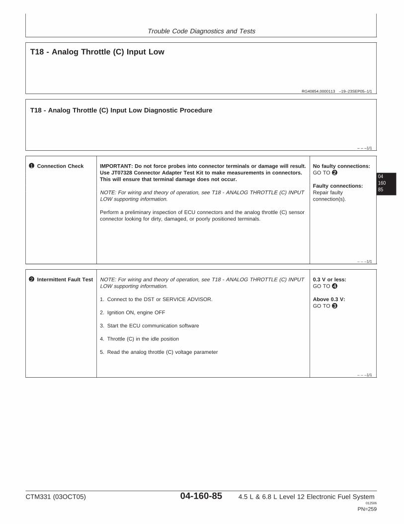
Trouble Code Diagnostics and Tests
RG40854,0000113 –19–23SEP05–1/1
T18 - Analog Throttle (C) Input Low
– – –1/1
T18 - Analog Throttle (C) Input Low Diagnostic Procedure
0416085
– – –1/1
1 Connection Check IMPORTANT: Do not force probes into connector terminals or damage will result.Use JT07328 Connector Adapter Test Kit to make measurements in connectors.This will ensure that terminal damage does not occur.
NOTE: For wiring and theory of operation, see T18 - ANALOG THROTTLE (C) INPUTLOW supporting information.
Perform a preliminary inspection of ECU connectors and the analog throttle (C) sensorconnector looking for dirty, damaged, or poorly positioned terminals.
No faulty connections:GO TO 2
Faulty connections:Repair faultyconnection(s).
– – –1/1
2 Intermittent Fault Test NOTE: For wiring and theory of operation, see T18 - ANALOG THROTTLE (C) INPUTLOW supporting information.
1. Connect to the DST or SERVICE ADVISOR.
2. Ignition ON, engine OFF
3. Start the ECU communication software
4. Throttle (C) in the idle position
5. Read the analog throttle (C) voltage parameter
0.3 V or less:GO TO 4
Above 0.3 V:GO TO 3
CTM331 (03OCT05) 04-160-85 4.5 L & 6.8 L Level 12 Electronic Fuel System012506
PN=259
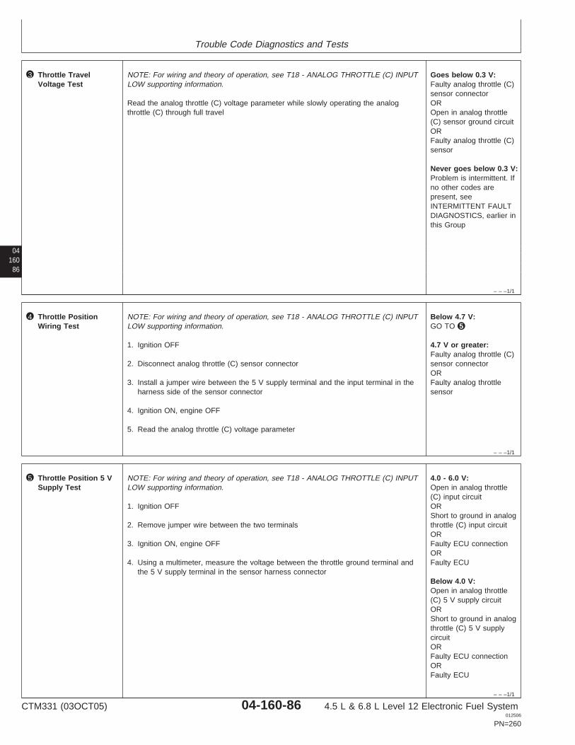
Trouble Code Diagnostics and Tests
04160
86
– – –1/1
3 Throttle TravelVoltage Test
NOTE: For wiring and theory of operation, see T18 - ANALOG THROTTLE (C) INPUTLOW supporting information.
Read the analog throttle (C) voltage parameter while slowly operating the analogthrottle (C) through full travel
Goes below 0.3 V:Faulty analog throttle (C)sensor connectorOROpen in analog throttle(C) sensor ground circuitORFaulty analog throttle (C)sensor
Never goes below 0.3 V:Problem is intermittent. Ifno other codes arepresent, seeINTERMITTENT FAULTDIAGNOSTICS, earlier inthis Group
– – –1/1
4 Throttle PositionWiring Test
NOTE: For wiring and theory of operation, see T18 - ANALOG THROTTLE (C) INPUTLOW supporting information.
1. Ignition OFF
2. Disconnect analog throttle (C) sensor connector
3. Install a jumper wire between the 5 V supply terminal and the input terminal in theharness side of the sensor connector
4. Ignition ON, engine OFF
5. Read the analog throttle (C) voltage parameter
Below 4.7 V:GO TO 5
4.7 V or greater:Faulty analog throttle (C)sensor connectorORFaulty analog throttlesensor
– – –1/1
5 Throttle Position 5 VSupply Test
NOTE: For wiring and theory of operation, see T18 - ANALOG THROTTLE (C) INPUTLOW supporting information.
1. Ignition OFF
2. Remove jumper wire between the two terminals
3. Ignition ON, engine OFF
4. Using a multimeter, measure the voltage between the throttle ground terminal andthe 5 V supply terminal in the sensor harness connector
4.0 - 6.0 V:Open in analog throttle(C) input circuitORShort to ground in analogthrottle (C) input circuitORFaulty ECU connectionORFaulty ECU
Below 4.0 V:Open in analog throttle(C) 5 V supply circuitORShort to ground in analogthrottle (C) 5 V supplycircuitORFaulty ECU connectionORFaulty ECU
CTM331 (03OCT05) 04-160-86 4.5 L & 6.8 L Level 12 Electronic Fuel System012506
PN=260
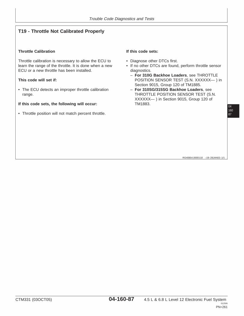
Trouble Code Diagnostics and Tests
0416087
RG40854,0000118 –19–28JAN02–1/1
T19 - Throttle Not Calibrated Properly
Throttle Calibration
Throttle calibration is necessary to allow the ECU tolearn the range of the throttle. It is done when a newECU or a new throttle has been installed.
This code will set if:
• The ECU detects an improper throttle calibrationrange.
If this code sets, the following will occur:
• Throttle position will not match percent throttle.
If this code sets:
• Diagnose other DTCs first.• If no other DTCs are found, perform throttle sensor
diagnostics.– For 310G Backhoe Loaders, see THROTTLE
POSITION SENSOR TEST (S.N. XXXXXX— ) inSection 9015, Group 120 of TM1885.
– For 310SG/315SG Backhoe Loaders, seeTHROTTLE POSITION SENSOR TEST (S.N.XXXXXX— ) in Section 9015, Group 120 ofTM1883.
CTM331 (03OCT05) 04-160-87 4.5 L & 6.8 L Level 12 Electronic Fuel System012506
PN=261
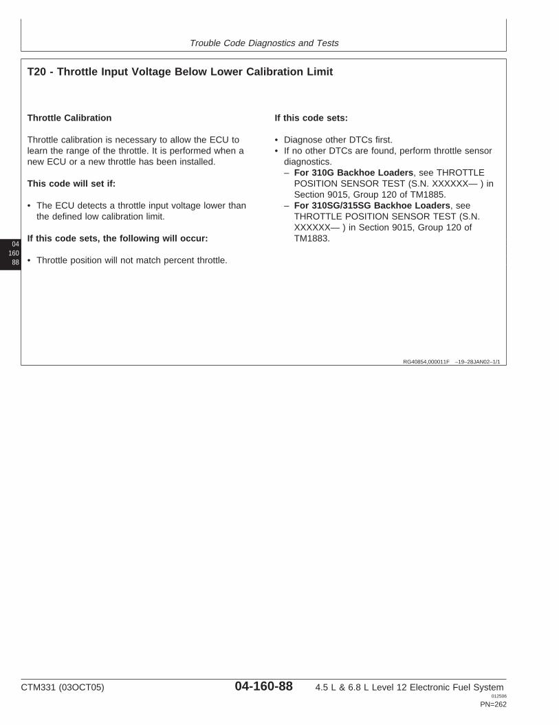
Trouble Code Diagnostics and Tests
04160
88
RG40854,000011F –19–28JAN02–1/1
T20 - Throttle Input Voltage Below Lower Calibration Limit
Throttle Calibration
Throttle calibration is necessary to allow the ECU tolearn the range of the throttle. It is performed when anew ECU or a new throttle has been installed.
This code will set if:
• The ECU detects a throttle input voltage lower thanthe defined low calibration limit.
If this code sets, the following will occur:
• Throttle position will not match percent throttle.
If this code sets:
• Diagnose other DTCs first.• If no other DTCs are found, perform throttle sensor
diagnostics.– For 310G Backhoe Loaders, see THROTTLE
POSITION SENSOR TEST (S.N. XXXXXX— ) inSection 9015, Group 120 of TM1885.
– For 310SG/315SG Backhoe Loaders, seeTHROTTLE POSITION SENSOR TEST (S.N.XXXXXX— ) in Section 9015, Group 120 ofTM1883.
CTM331 (03OCT05) 04-160-88 4.5 L & 6.8 L Level 12 Electronic Fuel System012506
PN=262
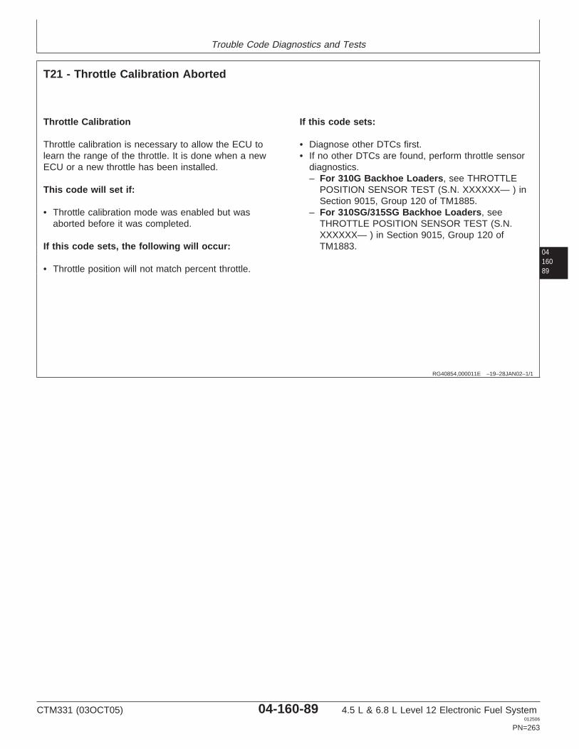
Trouble Code Diagnostics and Tests
0416089
RG40854,000011E –19–28JAN02–1/1
T21 - Throttle Calibration Aborted
Throttle Calibration
Throttle calibration is necessary to allow the ECU tolearn the range of the throttle. It is done when a newECU or a new throttle has been installed.
This code will set if:
• Throttle calibration mode was enabled but wasaborted before it was completed.
If this code sets, the following will occur:
• Throttle position will not match percent throttle.
If this code sets:
• Diagnose other DTCs first.• If no other DTCs are found, perform throttle sensor
diagnostics.– For 310G Backhoe Loaders, see THROTTLE
POSITION SENSOR TEST (S.N. XXXXXX— ) inSection 9015, Group 120 of TM1885.
– For 310SG/315SG Backhoe Loaders, seeTHROTTLE POSITION SENSOR TEST (S.N.XXXXXX— ) in Section 9015, Group 120 ofTM1883.
CTM331 (03OCT05) 04-160-89 4.5 L & 6.8 L Level 12 Electronic Fuel System012506
PN=263
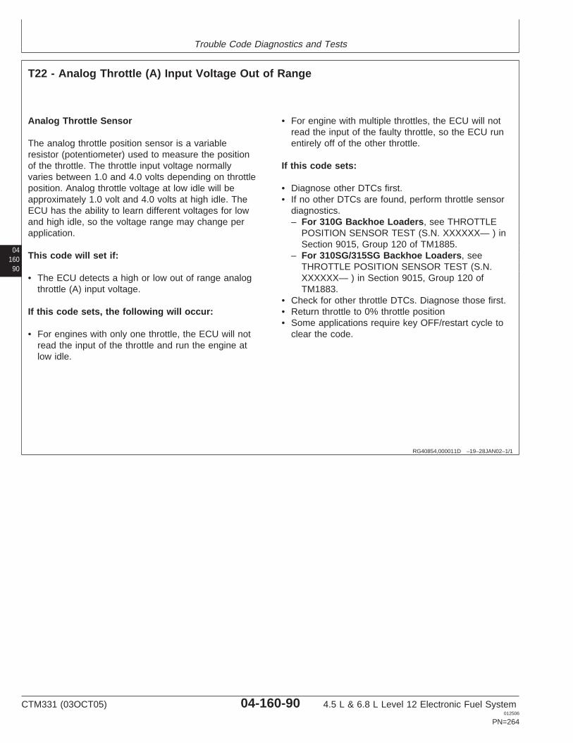
Trouble Code Diagnostics and Tests
04160
90
RG40854,000011D –19–28JAN02–1/1
T22 - Analog Throttle (A) Input Voltage Out of Range
Analog Throttle Sensor
The analog throttle position sensor is a variableresistor (potentiometer) used to measure the positionof the throttle. The throttle input voltage normallyvaries between 1.0 and 4.0 volts depending on throttleposition. Analog throttle voltage at low idle will beapproximately 1.0 volt and 4.0 volts at high idle. TheECU has the ability to learn different voltages for lowand high idle, so the voltage range may change perapplication.
This code will set if:
• The ECU detects a high or low out of range analogthrottle (A) input voltage.
If this code sets, the following will occur:
• For engines with only one throttle, the ECU will notread the input of the throttle and run the engine atlow idle.
• For engine with multiple throttles, the ECU will notread the input of the faulty throttle, so the ECU runentirely off of the other throttle.
If this code sets:
• Diagnose other DTCs first.• If no other DTCs are found, perform throttle sensor
diagnostics.– For 310G Backhoe Loaders, see THROTTLE
POSITION SENSOR TEST (S.N. XXXXXX— ) inSection 9015, Group 120 of TM1885.
– For 310SG/315SG Backhoe Loaders, seeTHROTTLE POSITION SENSOR TEST (S.N.XXXXXX— ) in Section 9015, Group 120 ofTM1883.
• Check for other throttle DTCs. Diagnose those first.• Return throttle to 0% throttle position• Some applications require key OFF/restart cycle to
clear the code.
CTM331 (03OCT05) 04-160-90 4.5 L & 6.8 L Level 12 Electronic Fuel System012506
PN=264

Trouble Code Diagnostics and Tests
0416091
RG40854,000011C –19–28JAN02–1/1
T23 - Multi-state Throttle Input Voltage Out of Range
Multi-state Throttle Switch
• Multi-state throttle is composed of an idle switch thatallows engine speed to be at high or low idle. Onsome applications, there is a bump up and a bumpdown feature. This allows for high and low idle to becontrolled.
• On certain applications, an additional throttle is usedin addition to the multi-state throttle. If the desiredengine speed of the additional throttle is greater thanthe multi-state throttle, the multi-state throttle will beoverridden. When the desired engine speed of themulti-state throttle is greater than the additionalthrottle, the multi-state throttle will be in total control.
This code will set if:
• The ECU detects a high or low out of rangemulti-state throttle input voltage.
If this code sets, the following will occur:
• The engine will not run if this code is active.
If this code sets:
• Check to see if DTC 000091.03 or 4 is active.Diagnose those first.
• Return throttle to 0% throttle position
CTM331 (03OCT05) 04-160-91 4.5 L & 6.8 L Level 12 Electronic Fuel System012506
PN=265
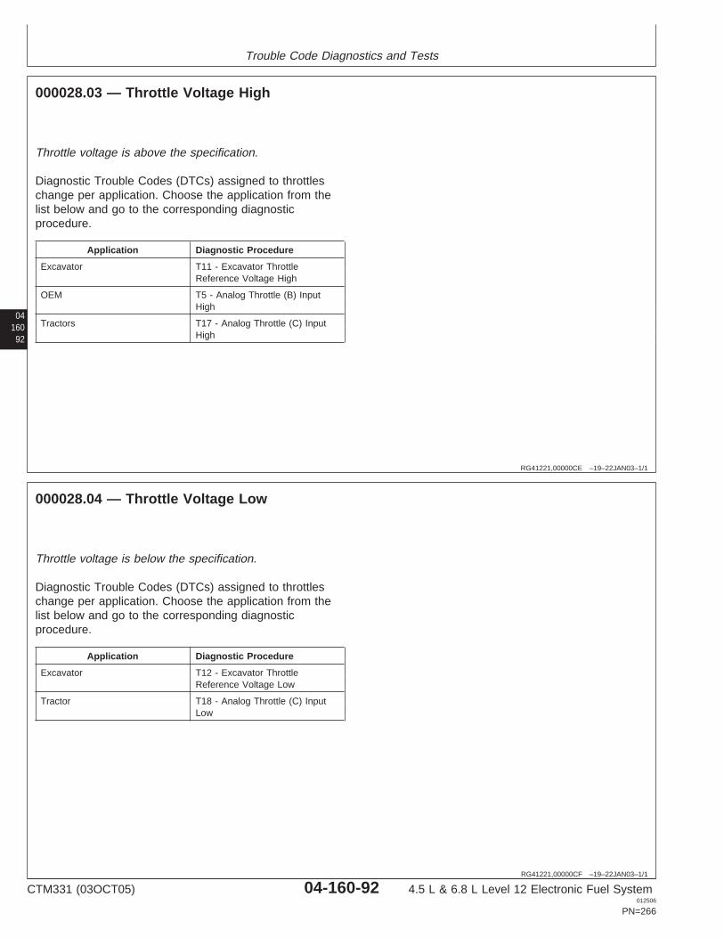
Trouble Code Diagnostics and Tests
04160
92
RG41221,00000CE –19–22JAN03–1/1
000028.03 — Throttle Voltage High
Throttle voltage is above the specification.
Diagnostic Trouble Codes (DTCs) assigned to throttleschange per application. Choose the application from thelist below and go to the corresponding diagnosticprocedure.
Application Diagnostic Procedure
Excavator T11 - Excavator ThrottleReference Voltage High
OEM T5 - Analog Throttle (B) InputHigh
Tractors T17 - Analog Throttle (C) InputHigh
RG41221,00000CF –19–22JAN03–1/1
000028.04 — Throttle Voltage Low
Throttle voltage is below the specification.
Diagnostic Trouble Codes (DTCs) assigned to throttleschange per application. Choose the application from thelist below and go to the corresponding diagnosticprocedure.
Application Diagnostic Procedure
Excavator T12 - Excavator ThrottleReference Voltage Low
Tractor T18 - Analog Throttle (C) InputLow
CTM331 (03OCT05) 04-160-92 4.5 L & 6.8 L Level 12 Electronic Fuel System012506
PN=266
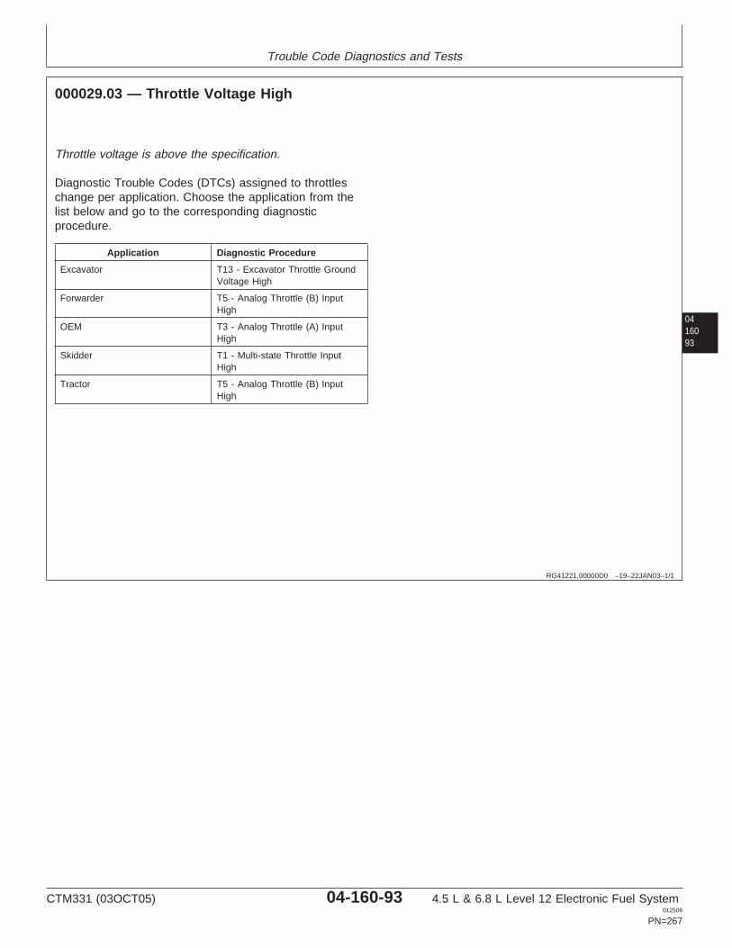
Trouble Code Diagnostics and Tests
0416093
RG41221,00000D0 –19–22JAN03–1/1
000029.03 — Throttle Voltage High
Throttle voltage is above the specification.
Diagnostic Trouble Codes (DTCs) assigned to throttleschange per application. Choose the application from thelist below and go to the corresponding diagnosticprocedure.
Application Diagnostic Procedure
Excavator T13 - Excavator Throttle GroundVoltage High
Forwarder T5 - Analog Throttle (B) InputHigh
OEM T3 - Analog Throttle (A) InputHigh
Skidder T1 - Multi-state Throttle InputHigh
Tractor T5 - Analog Throttle (B) InputHigh
CTM331 (03OCT05) 04-160-93 4.5 L & 6.8 L Level 12 Electronic Fuel System012506
PN=267
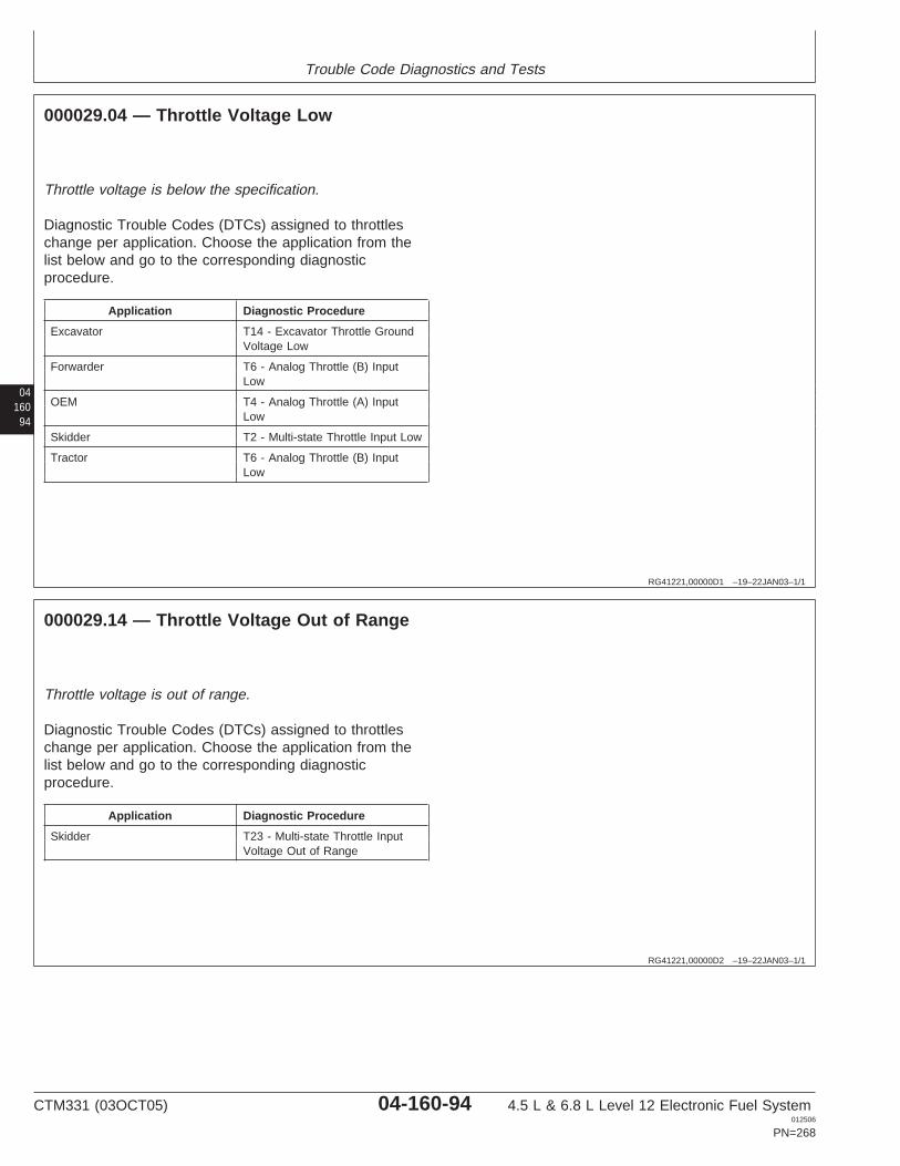
Trouble Code Diagnostics and Tests
04160
94
RG41221,00000D1 –19–22JAN03–1/1
000029.04 — Throttle Voltage Low
Throttle voltage is below the specification.
Diagnostic Trouble Codes (DTCs) assigned to throttleschange per application. Choose the application from thelist below and go to the corresponding diagnosticprocedure.
Application Diagnostic Procedure
Excavator T14 - Excavator Throttle GroundVoltage Low
Forwarder T6 - Analog Throttle (B) InputLow
OEM T4 - Analog Throttle (A) InputLow
Skidder T2 - Multi-state Throttle Input Low
Tractor T6 - Analog Throttle (B) InputLow
RG41221,00000D2 –19–22JAN03–1/1
000029.14 — Throttle Voltage Out of Range
Throttle voltage is out of range.
Diagnostic Trouble Codes (DTCs) assigned to throttleschange per application. Choose the application from thelist below and go to the corresponding diagnosticprocedure.
Application Diagnostic Procedure
Skidder T23 - Multi-state Throttle InputVoltage Out of Range
CTM331 (03OCT05) 04-160-94 4.5 L & 6.8 L Level 12 Electronic Fuel System012506
PN=268

Trouble Code Diagnostics and Tests
0416095
CTM331 (03OCT05) 04-160-95 4.5 L & 6.8 L Level 12 Electronic Fuel System012506
PN=269
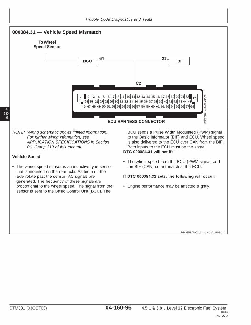
Trouble Code Diagnostics and Tests
04160
96
RG40854,0000114 –19–12AUG02–1/1
000084.31 — Vehicle Speed Mismatch
21L64
To WheelSpeed Sensor
ECU HARNESS CONNECTOR
46 68
26 27 28 29 30 31 32 33 34 35 36 37 38 39 40 41 42 43 44 4524 252 3 4 5 6 7 8 9 10 11 12 13 14 15 16 17 18 19 20 21 22
47 48 49 50 51 52 53 54 55 56 57 58 59 60 61 62 63 64 65 66 67
1 23
BCU BIF
C2
RG
1258
8–1
9–22
AU
G02
NOTE: Wiring schematic shows limited information.For further wiring information, seeAPPLICATION SPECIFICATIONS in Section06, Group 210 of this manual.
Vehicle Speed
• The wheel speed sensor is an inductive type sensorthat is mounted on the rear axle. As teeth on theaxle rotate past the sensor, AC signals aregenerated. The frequency of these signals areproportional to the wheel speed. The signal from thesensor is sent to the Basic Control Unit (BCU). The
BCU sends a Pulse Width Modulated (PWM) signalto the Basic Informator (BIF) and ECU. Wheel speedis also delivered to the ECU over CAN from the BIF.Both inputs to the ECU must be the same.
DTC 000084.31 will set if:
• The wheel speed from the BCU (PWM signal) andthe BIF (CAN) do not match at the ECU.
If DTC 000084.31 sets, the following will occur:
• Engine performance may be affected slightly.
CTM331 (03OCT05) 04-160-96 4.5 L & 6.8 L Level 12 Electronic Fuel System012506
PN=270
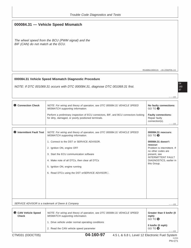
Trouble Code Diagnostics and Tests
RG40854,0000115 –19–23SEP05–1/1
000084.31 — Vehicle Speed Mismatch
The wheel speed from the BCU (PWM signal) and theBIF (CAN) do not match at the ECU.
0416097
– – –1/1
000084.31 Vehicle Speed Mismatch Diagnostic Procedure
NOTE: If DTC 001069.31 occurs with DTC 000084.31, diagnose DTC 001069.31 first.
– – –1/1
1 Connection Check NOTE: For wiring and theory of operation, see DTC 000084.31 VEHICLE SPEEDMISMATCH supporting information.
Perform a preliminary inspection of ECU connectors, BIF, and BCU connectors lookingfor dirty, damaged, or poorly positioned terminals.
No faulty connections:GO TO 2
Faulty connections:Repair faultyconnection(s).
– – –1/1
2 Intermittent Fault Test NOTE: For wiring and theory of operation, see DTC 000084.31 VEHICLE SPEEDMISMATCH supporting information.
1. Connect to the DST or SERVICE ADVISOR.
2. Ignition ON, engine OFF
3. Start the ECU communication software
4. Make note of all DTCs, then clear all DTCs
5. Ignition ON, engine running
6. Read DTCs using the DST orSERVICE ADVISOR.
000084.31 reoccurs:GO TO 3
000084.31 doesn’treoccur:Problem is intermittent. Ifno other codes arepresent, seeINTERMITTENT FAULTDIAGNOSTICS, earlier inthis Group.
SERVICE ADVISOR is a trademark of Deere & Company
– – –1/1
3 CAN Vehicle SpeedCheck
NOTE: For wiring and theory of operation, see DTC 000084.31 VEHICLE SPEEDMISMATCH supporting information.
1. Drive vehicle under normal operating conditions
2. Read the CAN vehicle speed parameter
Greater than 0 km/hr (0mph):GO TO 5
0 km/hr (0 mph):GO TO 4
CTM331 (03OCT05) 04-160-97 4.5 L & 6.8 L Level 12 Electronic Fuel System012506
PN=271
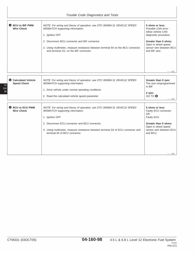
Trouble Code Diagnostics and Tests
– – –1/1
4 BCU to BIF PWMWire Check
NOTE: For wiring and theory of operation, see DTC 000084.31 VEHICLE SPEEDMISMATCH supporting information.
1. Ignition OFF
2. Disconnect BCU connector and BIF connector.
3. Using multimeter, measure resistance between terminal 64 on the BCU connectorand terminal 21L on the BIF connector.
5 ohms or less:Possible CAN error -follow vehicle CANdiagnostic procedure
Greater than 5 ohms:Open in wheel speedsensor wire between BCUand BIF wire.
04160
98
– – –1/1
5 Calculated VehicleSpeed Check
NOTE: For wiring and theory of operation, see DTC 000084.31 VEHICLE SPEEDMISMATCH supporting information.
1. Drive vehicle under normal operating conditions
2. Read the calculated vehicle speed parameter
Greater than 0 rpm:Tire size misprogrammedin BIF
0 rpm:GO TO 6
– – –1/1
6 BCU to ECU PWMWire Check
NOTE: For wiring and theory of operation, see DTC 000084.31 VEHICLE SPEEDMISMATCH supporting information.
1. Ignition OFF
2. Disconnect ECU connector and BCU connector.
3. Using multimeter, measure resistance between terminal D2 of ECU connector andterminal 64 of BCU connector.
5 ohms or less:Faulty ECU connectorORFaulty ECU
Greater than 5 ohms:Open in wheel speedsensor wire between ECUand BCU.
CTM331 (03OCT05) 04-160-98 4.5 L & 6.8 L Level 12 Electronic Fuel System012506
PN=272
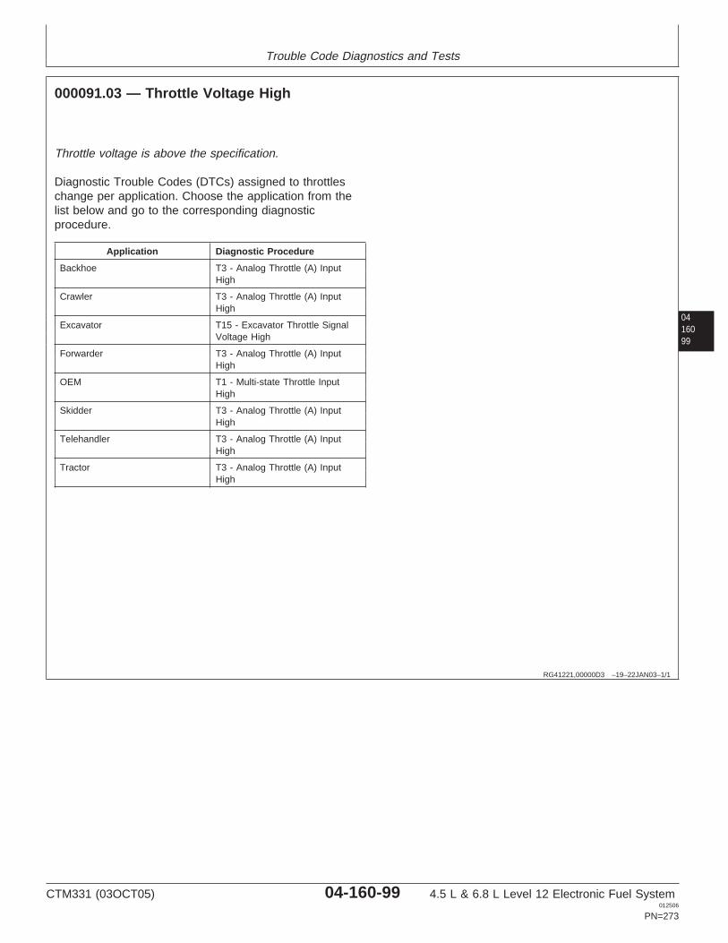
Trouble Code Diagnostics and Tests
0416099
RG41221,00000D3 –19–22JAN03–1/1
000091.03 — Throttle Voltage High
Throttle voltage is above the specification.
Diagnostic Trouble Codes (DTCs) assigned to throttleschange per application. Choose the application from thelist below and go to the corresponding diagnosticprocedure.
Application Diagnostic Procedure
Backhoe T3 - Analog Throttle (A) InputHigh
Crawler T3 - Analog Throttle (A) InputHigh
Excavator T15 - Excavator Throttle SignalVoltage High
Forwarder T3 - Analog Throttle (A) InputHigh
OEM T1 - Multi-state Throttle InputHigh
Skidder T3 - Analog Throttle (A) InputHigh
Telehandler T3 - Analog Throttle (A) InputHigh
Tractor T3 - Analog Throttle (A) InputHigh
CTM331 (03OCT05) 04-160-99 4.5 L & 6.8 L Level 12 Electronic Fuel System012506
PN=273
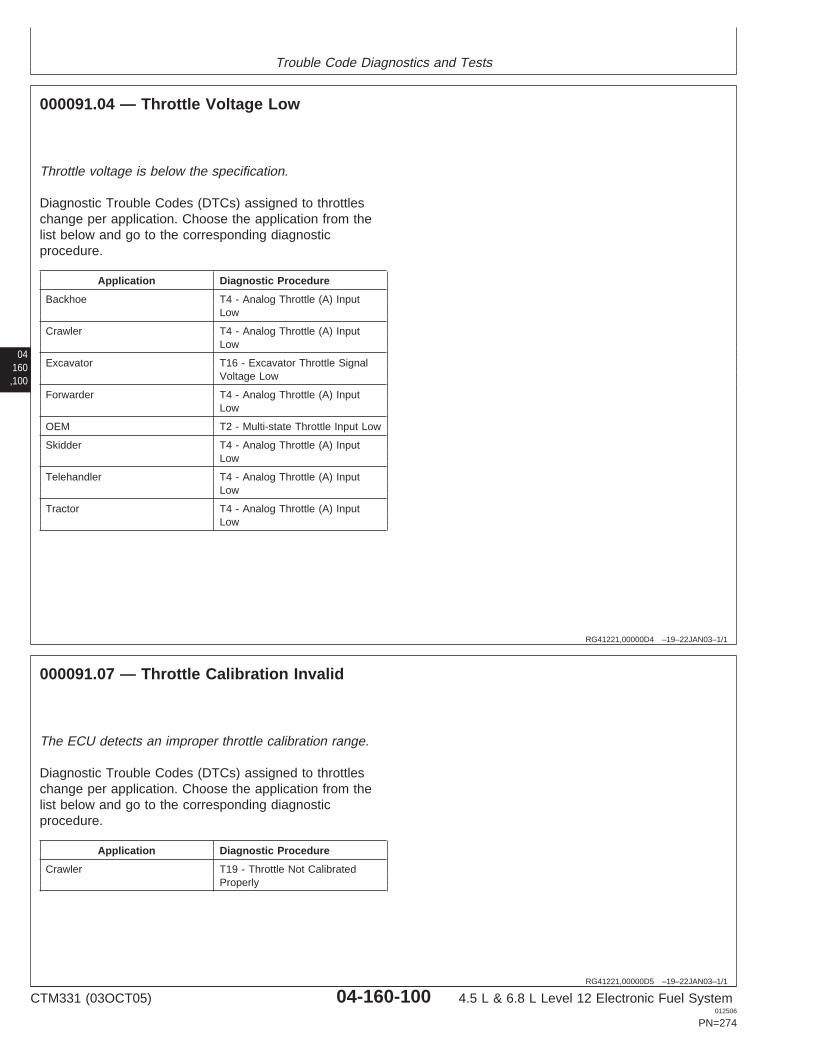
Trouble Code Diagnostics and Tests
04160,100
RG41221,00000D4 –19–22JAN03–1/1
000091.04 — Throttle Voltage Low
Throttle voltage is below the specification.
Diagnostic Trouble Codes (DTCs) assigned to throttleschange per application. Choose the application from thelist below and go to the corresponding diagnosticprocedure.
Application Diagnostic Procedure
Backhoe T4 - Analog Throttle (A) InputLow
Crawler T4 - Analog Throttle (A) InputLow
Excavator T16 - Excavator Throttle SignalVoltage Low
Forwarder T4 - Analog Throttle (A) InputLow
OEM T2 - Multi-state Throttle Input Low
Skidder T4 - Analog Throttle (A) InputLow
Telehandler T4 - Analog Throttle (A) InputLow
Tractor T4 - Analog Throttle (A) InputLow
RG41221,00000D5 –19–22JAN03–1/1
000091.07 — Throttle Calibration Invalid
The ECU detects an improper throttle calibration range.
Diagnostic Trouble Codes (DTCs) assigned to throttleschange per application. Choose the application from thelist below and go to the corresponding diagnosticprocedure.
Application Diagnostic Procedure
Crawler T19 - Throttle Not CalibratedProperly
CTM331 (03OCT05) 04-160-100 4.5 L & 6.8 L Level 12 Electronic Fuel System012506
PN=274
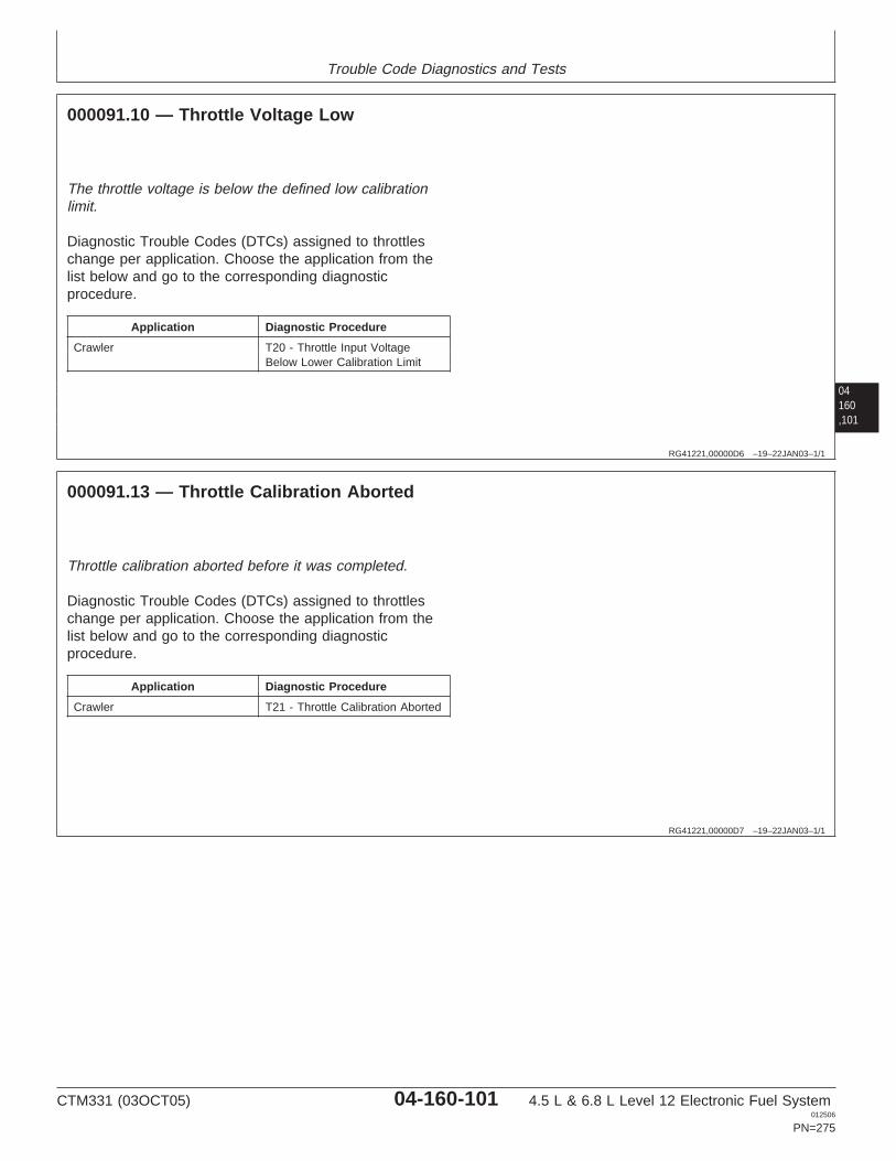
Trouble Code Diagnostics and Tests
04160,101
RG41221,00000D6 –19–22JAN03–1/1
000091.10 — Throttle Voltage Low
The throttle voltage is below the defined low calibrationlimit.
Diagnostic Trouble Codes (DTCs) assigned to throttleschange per application. Choose the application from thelist below and go to the corresponding diagnosticprocedure.
Application Diagnostic Procedure
Crawler T20 - Throttle Input VoltageBelow Lower Calibration Limit
RG41221,00000D7 –19–22JAN03–1/1
000091.13 — Throttle Calibration Aborted
Throttle calibration aborted before it was completed.
Diagnostic Trouble Codes (DTCs) assigned to throttleschange per application. Choose the application from thelist below and go to the corresponding diagnosticprocedure.
Application Diagnostic Procedure
Crawler T21 - Throttle Calibration Aborted
CTM331 (03OCT05) 04-160-101 4.5 L & 6.8 L Level 12 Electronic Fuel System012506
PN=275
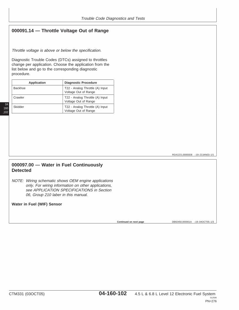
Trouble Code Diagnostics and Tests
04160,102
RG41221,00000D8 –19–22JAN03–1/1
000091.14 — Throttle Voltage Out of Range
Throttle voltage is above or below the specification.
Diagnostic Trouble Codes (DTCs) assigned to throttleschange per application. Choose the application from thelist below and go to the corresponding diagnosticprocedure.
Application Diagnostic Procedure
Backhoe T22 - Analog Throttle (A) InputVoltage Out of Range
Crawler T22 - Analog Throttle (A) InputVoltage Out of Range
Skidder T22 - Analog Throttle (A) InputVoltage Out of Range
DB92450,000001A –19–04OCT05–1/3
000097.00 — Water in Fuel ContinuouslyDetected
NOTE: Wiring schematic shows OEM engine applicationsonly. For wiring information on other applications,see APPLICATION SPECIFICATIONS in Section06, Group 210 laber in this manual.
Water in Fuel (WIF) Sensor
Continued on next page
CTM331 (03OCT05) 04-160-102 4.5 L & 6.8 L Level 12 Electronic Fuel System012506
PN=276
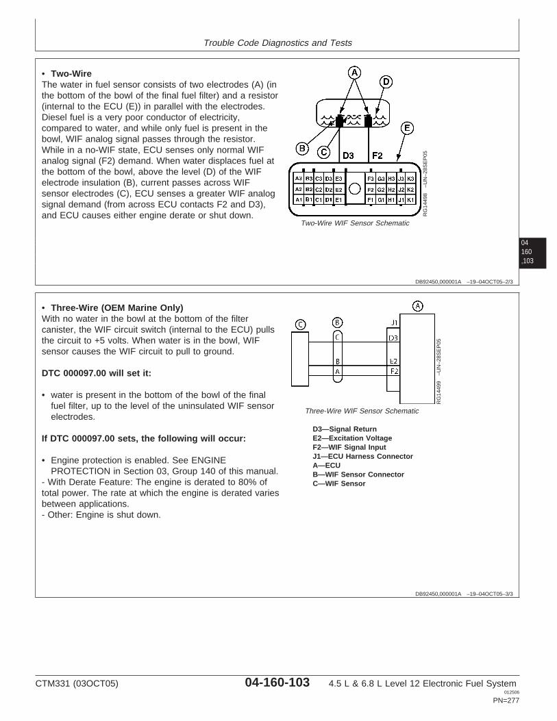
Trouble Code Diagnostics and Tests
04160,103
DB92450,000001A –19–04OCT05–2/3
RG
1449
8–U
N–2
8SE
P05
Two-Wire WIF Sensor Schematic
• Two-WireThe water in fuel sensor consists of two electrodes (A) (inthe bottom of the bowl of the final fuel filter) and a resistor(internal to the ECU (E)) in parallel with the electrodes.Diesel fuel is a very poor conductor of electricity,compared to water, and while only fuel is present in thebowl, WIF analog signal passes through the resistor.While in a no-WIF state, ECU senses only normal WIFanalog signal (F2) demand. When water displaces fuel atthe bottom of the bowl, above the level (D) of the WIFelectrode insulation (B), current passes across WIFsensor electrodes (C), ECU senses a greater WIF analogsignal demand (from across ECU contacts F2 and D3),and ECU causes either engine derate or shut down.
DB92450,000001A –19–04OCT05–3/3
RG
1449
9–U
N–2
8SE
P05
Three-Wire WIF Sensor Schematic
D3—Signal ReturnE2—Excitation VoltageF2—WIF Signal InputJ1—ECU Harness ConnectorA—ECUB—WIF Sensor ConnectorC—WIF Sensor
• Three-Wire (OEM Marine Only)With no water in the bowl at the bottom of the filtercanister, the WIF circuit switch (internal to the ECU) pullsthe circuit to +5 volts. When water is in the bowl, WIFsensor causes the WIF circuit to pull to ground.
DTC 000097.00 will set it:
• water is present in the bottom of the bowl of the finalfuel filter, up to the level of the uninsulated WIF sensorelectrodes.
If DTC 000097.00 sets, the following will occur:
• Engine protection is enabled. See ENGINEPROTECTION in Section 03, Group 140 of this manual.
- With Derate Feature: The engine is derated to 80% oftotal power. The rate at which the engine is derated variesbetween applications.- Other: Engine is shut down.
CTM331 (03OCT05) 04-160-103 4.5 L & 6.8 L Level 12 Electronic Fuel System012506
PN=277
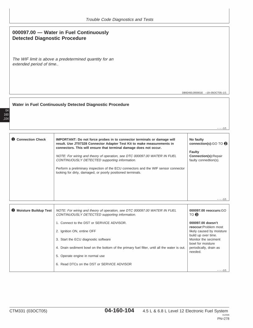
Trouble Code Diagnostics and Tests
DB92450,000001E –19–05OCT05–1/1
000097.00 — Water in Fuel ContinuouslyDetected Diagnostic Procedure
The WIF limit is above a predetermined quantity for anextended period of time..
04160,104
– – –1/1
Water in Fuel Continuously Detected Diagnostic Procedure
– – –1/1
1 Connection Check IMPORTANT: Do not force probes in to connector terminals or damage willresult. Use JT07328 Connector Adapter Test Kit to make measurements inconnectors. This will ensure that terminal damage does not occur.
NOTE: For wiring and theory of operation, see DTC 000097.00 WATER IN FUELCONTINUOUSLY DETECTED supporting information.
Perform a preliminary inspection of the ECU connectors and the WIF sensor connectorlooking for dirty, damaged, or poorly positioned terminals.
No faultyconnection(s):GO TO 2 .
FaultyConnection(s):Repairfaulty connedtion(s).
– – –1/1
2 Moisture Buildup Test NOTE: For wiring and theory of operation, see DTC 000097.00 WATER IN FUELCONTINUOUSLY DETECTED supporting information.
1. Connect to the DST or SERVICE ADVISOR.
2. Ignition ON, entine OFF
3. Start the ECU diagnostic software
4. Drain sediment bowl on the bottom of the primary fuel filter, until all the water is out.
5. Operate engine in normal use
6. Read DTCs on the DST or SERVICE ADVISOR
000097.00 reoccurs:GOTO 3
000097.00 doesn’treoccur:Problem mostlikely caused by moisturebuild up over time.Monitor the secimentbowl for moistureperiodically, drain asneeded.
CTM331 (03OCT05) 04-160-104 4.5 L & 6.8 L Level 12 Electronic Fuel System012506
PN=278
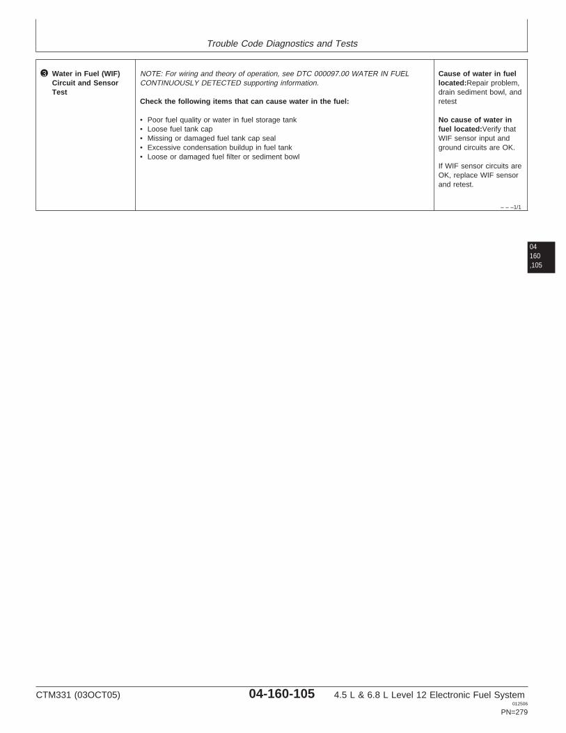
Trouble Code Diagnostics and Tests
– – –1/1
3 Water in Fuel (WIF)Circuit and SensorTest
NOTE: For wiring and theory of operation, see DTC 000097.00 WATER IN FUELCONTINUOUSLY DETECTED supporting information.
Check the following items that can cause water in the fuel:
• Poor fuel quality or water in fuel storage tank• Loose fuel tank cap• Missing or damaged fuel tank cap seal• Excessive condensation buildup in fuel tank• Loose or damaged fuel filter or sediment bowl
Cause of water in fuellocated:Repair problem,drain sediment bowl, andretest
No cause of water infuel located:Verify thatWIF sensor input andground circuits are OK.
If WIF sensor circuits areOK, replace WIF sensorand retest.
04160,105
CTM331 (03OCT05) 04-160-105 4.5 L & 6.8 L Level 12 Electronic Fuel System012506
PN=279
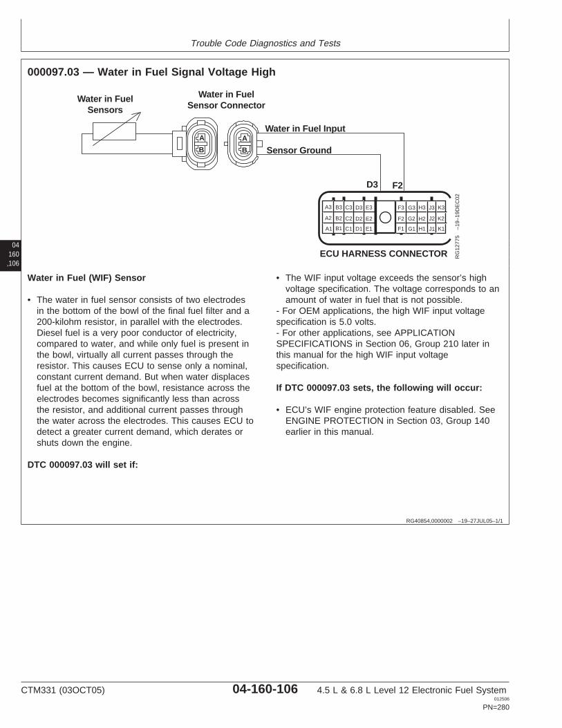
Trouble Code Diagnostics and Tests
04160,106
RG40854,0000002 –19–27JUL05–1/1
000097.03 — Water in Fuel Signal Voltage High
A
B
A
B
Water in FuelSensors
Water in FuelSensor Connector
Water in Fuel Input
Sensor Ground
D3 F2
A1
A2
A3 B3 C3 D3 E3
B2 C2 D2 E2
B1 C1 D1 E1 F1
F2
F3 G3 H3 J3 K3
G2 H2 J2 K2
G1 H1 J1 K1
ECU HARNESS CONNECTOR RG
1277
5–1
9–19
DE
C02
Water in Fuel (WIF) Sensor
• The water in fuel sensor consists of two electrodesin the bottom of the bowl of the final fuel filter and a200-kilohm resistor, in parallel with the electrodes.Diesel fuel is a very poor conductor of electricity,compared to water, and while only fuel is present inthe bowl, virtually all current passes through theresistor. This causes ECU to sense only a nominal,constant current demand. But when water displacesfuel at the bottom of the bowl, resistance across theelectrodes becomes significantly less than acrossthe resistor, and additional current passes throughthe water across the electrodes. This causes ECU todetect a greater current demand, which derates orshuts down the engine.
DTC 000097.03 will set if:
• The WIF input voltage exceeds the sensor’s highvoltage specification. The voltage corresponds to anamount of water in fuel that is not possible.
- For OEM applications, the high WIF input voltagespecification is 5.0 volts.- For other applications, see APPLICATIONSPECIFICATIONS in Section 06, Group 210 later inthis manual for the high WIF input voltagespecification.
If DTC 000097.03 sets, the following will occur:
• ECU’s WIF engine protection feature disabled. SeeENGINE PROTECTION in Section 03, Group 140earlier in this manual.
CTM331 (03OCT05) 04-160-106 4.5 L & 6.8 L Level 12 Electronic Fuel System012506
PN=280

Trouble Code Diagnostics and Tests
RG40854,0000003 –19–23SEP05–1/1
000097.03 — Water in Fuel Signal Voltage High
The WIF input voltage exceeds the sensor’s highvoltage specification. The voltage corresponds to anamount of water in fuel that is not possible.
04160,107
– – –1/1
000097.03 Water In Fuel Signal Voltage High Diagnostic Procedure
– – –1/1
1 Connection Check IMPORTANT: Do not force probes into connector terminals or damage will result.Use JT07328 Connector Adapter Test Kit to make measurements in connectors.This will ensure that terminal damage does not occur.
NOTE: For wiring and theory of operation, see DTC 000097.03 WATER IN FUELSIGNAL VOLTAGE HIGH supporting information.
Perform a preliminary inspection of the ECU connectors and the WIF sensor connectorlooking for dirty, damaged, or poorly positioned terminals.
No faulty connection(s):GO TO 2
Faulty Connections:Repair faultyconnection(s).
– – –1/1
2 Intermittent Fault Test NOTE: For wiring and theory of operation, see DTC 000097.03 WATER IN FUELSIGNAL VOLTAGE HIGH supporting information.
1. Connect to the DST or SERVICE ADVISOR.
2. Ignition ON, engine OFF
3. Start the ECU diagnostic software
4. Make note of any DTCs, then clear all DTCs.
5. Ignition ON, engine OFF
6. Read DTCs using the DST orSERVICE ADVISOR.
000097.03 reoccurs:GO TO 3
000097.03 does notreoccur:Problem is intermittent. Ifno other codes arepresent, seeINTERMITTENT FAULTDIAGNOSTICS earlier inthis Group.
SERVICE ADVISOR is a trademark of Deere & Company
CTM331 (03OCT05) 04-160-107 4.5 L & 6.8 L Level 12 Electronic Fuel System012506
PN=281
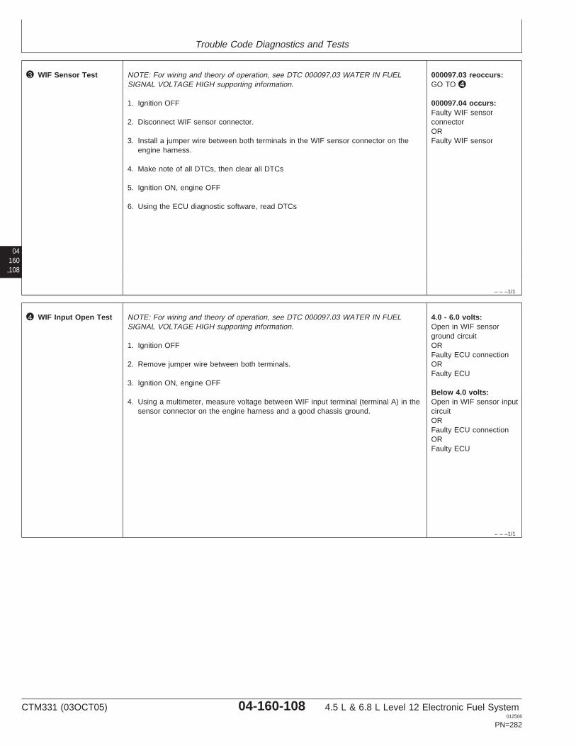
Trouble Code Diagnostics and Tests
04160,108
– – –1/1
3 WIF Sensor Test NOTE: For wiring and theory of operation, see DTC 000097.03 WATER IN FUELSIGNAL VOLTAGE HIGH supporting information.
1. Ignition OFF
2. Disconnect WIF sensor connector.
3. Install a jumper wire between both terminals in the WIF sensor connector on theengine harness.
4. Make note of all DTCs, then clear all DTCs
5. Ignition ON, engine OFF
6. Using the ECU diagnostic software, read DTCs
000097.03 reoccurs:GO TO 4
000097.04 occurs:Faulty WIF sensorconnectorORFaulty WIF sensor
– – –1/1
4 WIF Input Open Test NOTE: For wiring and theory of operation, see DTC 000097.03 WATER IN FUELSIGNAL VOLTAGE HIGH supporting information.
1. Ignition OFF
2. Remove jumper wire between both terminals.
3. Ignition ON, engine OFF
4. Using a multimeter, measure voltage between WIF input terminal (terminal A) in thesensor connector on the engine harness and a good chassis ground.
4.0 - 6.0 volts:Open in WIF sensorground circuitORFaulty ECU connectionORFaulty ECU
Below 4.0 volts:Open in WIF sensor inputcircuitORFaulty ECU connectionORFaulty ECU
CTM331 (03OCT05) 04-160-108 4.5 L & 6.8 L Level 12 Electronic Fuel System012506
PN=282

Trouble Code Diagnostics and Tests
04160,109
CTM331 (03OCT05) 04-160-109 4.5 L & 6.8 L Level 12 Electronic Fuel System012506
PN=283
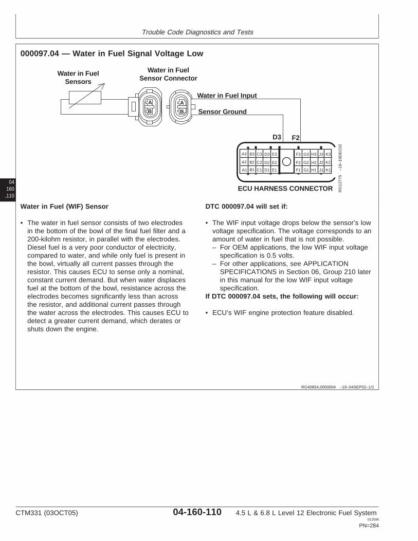
Trouble Code Diagnostics and Tests
04160,110
RG40854,0000004 –19–04SEP02–1/1
000097.04 — Water in Fuel Signal Voltage Low
A
B
A
B
Water in FuelSensors
Water in FuelSensor Connector
Water in Fuel Input
Sensor Ground
D3 F2
A1
A2
A3 B3 C3 D3 E3
B2 C2 D2 E2
B1 C1 D1 E1 F1
F2
F3 G3 H3 J3 K3
G2 H2 J2 K2
G1 H1 J1 K1
ECU HARNESS CONNECTOR RG
1277
5–1
9–19
DE
C02
Water in Fuel (WIF) Sensor
• The water in fuel sensor consists of two electrodesin the bottom of the bowl of the final fuel filter and a200-kilohm resistor, in parallel with the electrodes.Diesel fuel is a very poor conductor of electricity,compared to water, and while only fuel is present inthe bowl, virtually all current passes through theresistor. This causes ECU to sense only a nominal,constant current demand. But when water displacesfuel at the bottom of the bowl, resistance across theelectrodes becomes significantly less than acrossthe resistor, and additional current passes throughthe water across the electrodes. This causes ECU todetect a greater current demand, which derates orshuts down the engine.
DTC 000097.04 will set if:
• The WIF input voltage drops below the sensor’s lowvoltage specification. The voltage corresponds to anamount of water in fuel that is not possible.– For OEM applications, the low WIF input voltage
specification is 0.5 volts.– For other applications, see APPLICATION
SPECIFICATIONS in Section 06, Group 210 laterin this manual for the low WIF input voltagespecification.
If DTC 000097.04 sets, the following will occur:
• ECU’s WIF engine protection feature disabled.
CTM331 (03OCT05) 04-160-110 4.5 L & 6.8 L Level 12 Electronic Fuel System012506
PN=284
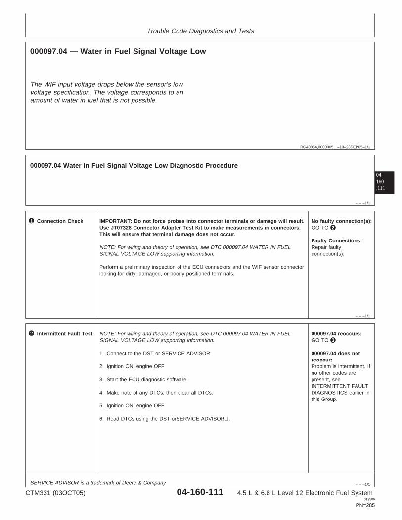
Trouble Code Diagnostics and Tests
RG40854,0000005 –19–23SEP05–1/1
000097.04 — Water in Fuel Signal Voltage Low
The WIF input voltage drops below the sensor’s lowvoltage specification. The voltage corresponds to anamount of water in fuel that is not possible.
04160,111
– – –1/1
000097.04 Water In Fuel Signal Voltage Low Diagnostic Procedure
– – –1/1
1 Connection Check IMPORTANT: Do not force probes into connector terminals or damage will result.Use JT07328 Connector Adapter Test Kit to make measurements in connectors.This will ensure that terminal damage does not occur.
NOTE: For wiring and theory of operation, see DTC 000097.04 WATER IN FUELSIGNAL VOLTAGE LOW supporting information.
Perform a preliminary inspection of the ECU connectors and the WIF sensor connectorlooking for dirty, damaged, or poorly positioned terminals.
No faulty connection(s):GO TO 2
Faulty Connections:Repair faultyconnection(s).
– – –1/1
2 Intermittent Fault Test NOTE: For wiring and theory of operation, see DTC 000097.04 WATER IN FUELSIGNAL VOLTAGE LOW supporting information.
1. Connect to the DST or SERVICE ADVISOR.
2. Ignition ON, engine OFF
3. Start the ECU diagnostic software
4. Make note of any DTCs, then clear all DTCs.
5. Ignition ON, engine OFF
6. Read DTCs using the DST orSERVICE ADVISOR.
000097.04 reoccurs:GO TO 3
000097.04 does notreoccur:Problem is intermittent. Ifno other codes arepresent, seeINTERMITTENT FAULTDIAGNOSTICS earlier inthis Group.
SERVICE ADVISOR is a trademark of Deere & Company
CTM331 (03OCT05) 04-160-111 4.5 L & 6.8 L Level 12 Electronic Fuel System012506
PN=285
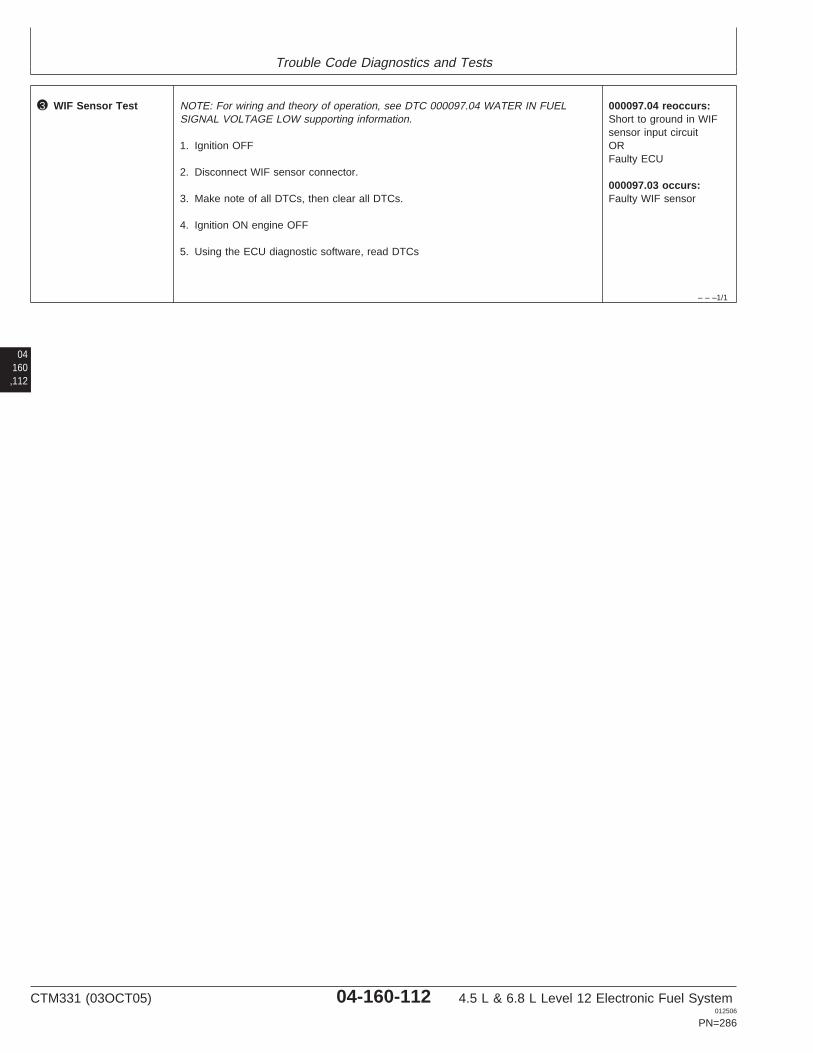
Trouble Code Diagnostics and Tests
– – –1/1
3 WIF Sensor Test NOTE: For wiring and theory of operation, see DTC 000097.04 WATER IN FUELSIGNAL VOLTAGE LOW supporting information.
1. Ignition OFF
2. Disconnect WIF sensor connector.
3. Make note of all DTCs, then clear all DTCs.
4. Ignition ON engine OFF
5. Using the ECU diagnostic software, read DTCs
000097.04 reoccurs:Short to ground in WIFsensor input circuitORFaulty ECU
000097.03 occurs:Faulty WIF sensor
04160,112
CTM331 (03OCT05) 04-160-112 4.5 L & 6.8 L Level 12 Electronic Fuel System012506
PN=286

Trouble Code Diagnostics and Tests
04160,113
CTM331 (03OCT05) 04-160-113 4.5 L & 6.8 L Level 12 Electronic Fuel System012506
PN=287
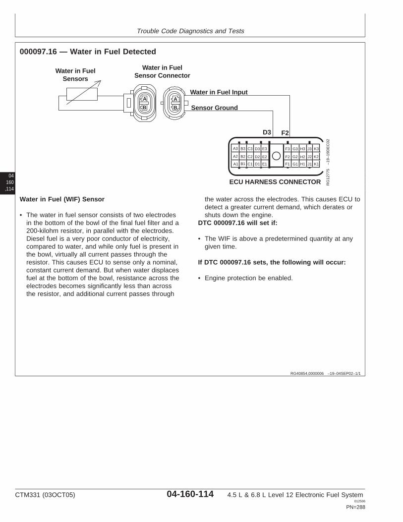
Trouble Code Diagnostics and Tests
04160,114
RG40854,0000006 –19–04SEP02–1/1
000097.16 — Water in Fuel Detected
A
B
A
B
Water in FuelSensors
Water in FuelSensor Connector
Water in Fuel Input
Sensor Ground
D3 F2
A1
A2
A3 B3 C3 D3 E3
B2 C2 D2 E2
B1 C1 D1 E1 F1
F2
F3 G3 H3 J3 K3
G2 H2 J2 K2
G1 H1 J1 K1
ECU HARNESS CONNECTOR RG
1277
5–1
9–19
DE
C02
Water in Fuel (WIF) Sensor
• The water in fuel sensor consists of two electrodesin the bottom of the bowl of the final fuel filter and a200-kilohm resistor, in parallel with the electrodes.Diesel fuel is a very poor conductor of electricity,compared to water, and while only fuel is present inthe bowl, virtually all current passes through theresistor. This causes ECU to sense only a nominal,constant current demand. But when water displacesfuel at the bottom of the bowl, resistance across theelectrodes becomes significantly less than acrossthe resistor, and additional current passes through
the water across the electrodes. This causes ECU todetect a greater current demand, which derates orshuts down the engine.
DTC 000097.16 will set if:
• The WIF is above a predetermined quantity at anygiven time.
If DTC 000097.16 sets, the following will occur:
• Engine protection be enabled.
CTM331 (03OCT05) 04-160-114 4.5 L & 6.8 L Level 12 Electronic Fuel System012506
PN=288
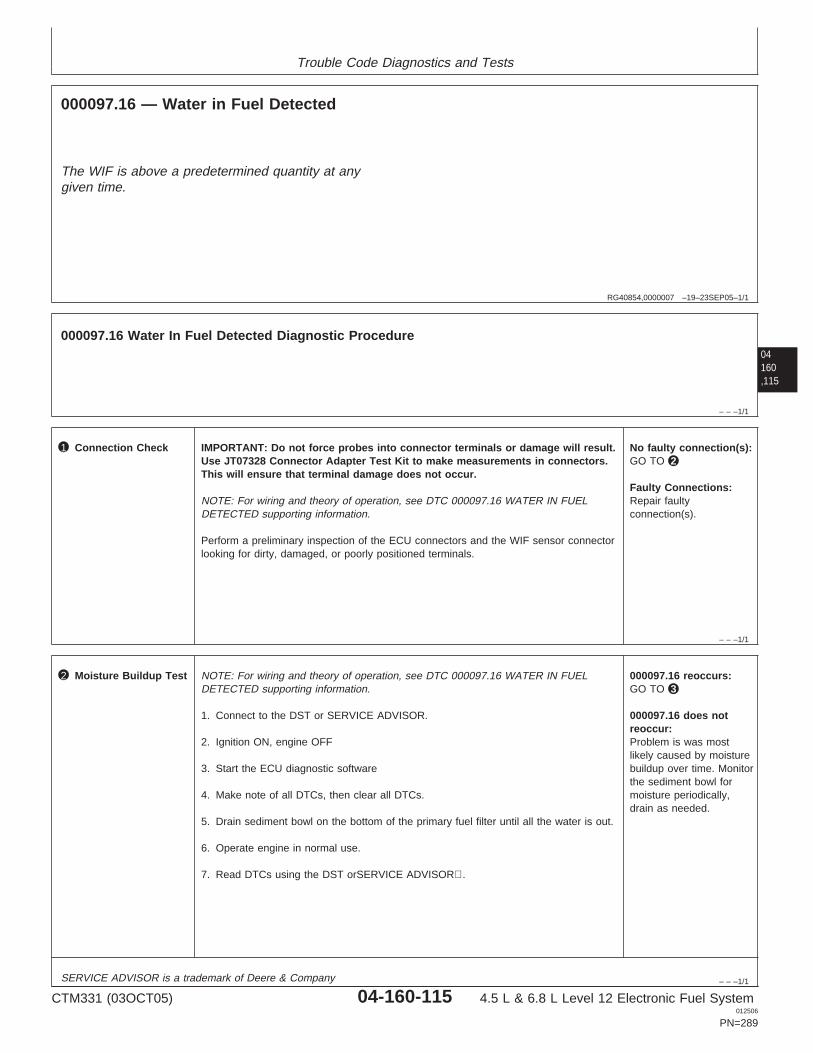
Trouble Code Diagnostics and Tests
RG40854,0000007 –19–23SEP05–1/1
000097.16 — Water in Fuel Detected
The WIF is above a predetermined quantity at anygiven time.
04160,115
– – –1/1
000097.16 Water In Fuel Detected Diagnostic Procedure
– – –1/1
1 Connection Check IMPORTANT: Do not force probes into connector terminals or damage will result.Use JT07328 Connector Adapter Test Kit to make measurements in connectors.This will ensure that terminal damage does not occur.
NOTE: For wiring and theory of operation, see DTC 000097.16 WATER IN FUELDETECTED supporting information.
Perform a preliminary inspection of the ECU connectors and the WIF sensor connectorlooking for dirty, damaged, or poorly positioned terminals.
No faulty connection(s):GO TO 2
Faulty Connections:Repair faultyconnection(s).
– – –1/1
2 Moisture Buildup Test NOTE: For wiring and theory of operation, see DTC 000097.16 WATER IN FUELDETECTED supporting information.
1. Connect to the DST or SERVICE ADVISOR.
2. Ignition ON, engine OFF
3. Start the ECU diagnostic software
4. Make note of all DTCs, then clear all DTCs.
5. Drain sediment bowl on the bottom of the primary fuel filter until all the water is out.
6. Operate engine in normal use.
7. Read DTCs using the DST orSERVICE ADVISOR.
000097.16 reoccurs:GO TO 3
000097.16 does notreoccur:Problem is was mostlikely caused by moisturebuildup over time. Monitorthe sediment bowl formoisture periodically,drain as needed.
SERVICE ADVISOR is a trademark of Deere & Company
CTM331 (03OCT05) 04-160-115 4.5 L & 6.8 L Level 12 Electronic Fuel System012506
PN=289
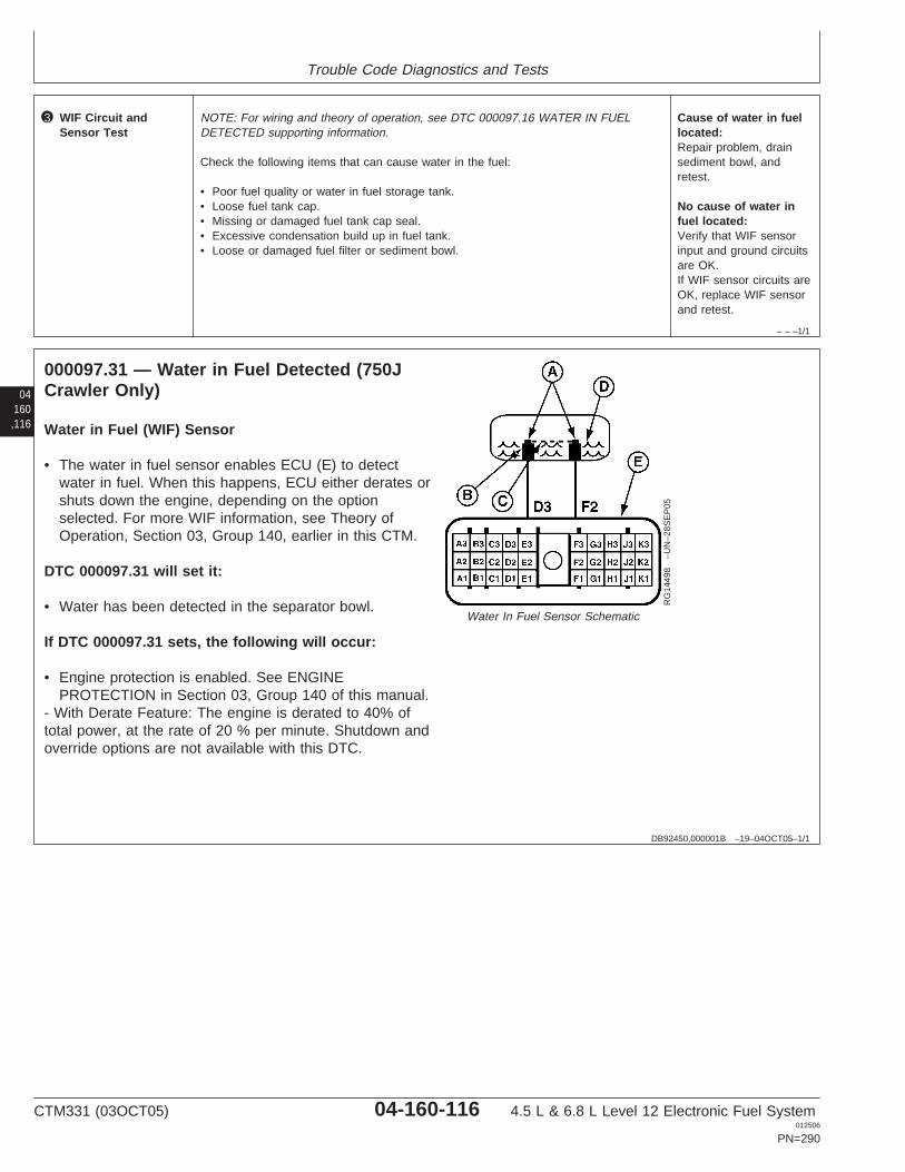
Trouble Code Diagnostics and Tests
– – –1/1
3 WIF Circuit andSensor Test
NOTE: For wiring and theory of operation, see DTC 000097.16 WATER IN FUELDETECTED supporting information.
Check the following items that can cause water in the fuel:
• Poor fuel quality or water in fuel storage tank.• Loose fuel tank cap.• Missing or damaged fuel tank cap seal.• Excessive condensation build up in fuel tank.• Loose or damaged fuel filter or sediment bowl.
Cause of water in fuellocated:Repair problem, drainsediment bowl, andretest.
No cause of water infuel located:Verify that WIF sensorinput and ground circuitsare OK.If WIF sensor circuits areOK, replace WIF sensorand retest.
04160,116
DB92450,000001B –19–04OCT05–1/1
000097.31 — Water in Fuel Detected (750JCrawler Only)
RG
1449
8–U
N–2
8SE
P05
Water In Fuel Sensor Schematic
Water in Fuel (WIF) Sensor
• The water in fuel sensor enables ECU (E) to detectwater in fuel. When this happens, ECU either derates orshuts down the engine, depending on the optionselected. For more WIF information, see Theory ofOperation, Section 03, Group 140, earlier in this CTM.
DTC 000097.31 will set it:
• Water has been detected in the separator bowl.
If DTC 000097.31 sets, the following will occur:
• Engine protection is enabled. See ENGINEPROTECTION in Section 03, Group 140 of this manual.
- With Derate Feature: The engine is derated to 40% oftotal power, at the rate of 20 % per minute. Shutdown andoverride options are not available with this DTC.
CTM331 (03OCT05) 04-160-116 4.5 L & 6.8 L Level 12 Electronic Fuel System012506
PN=290
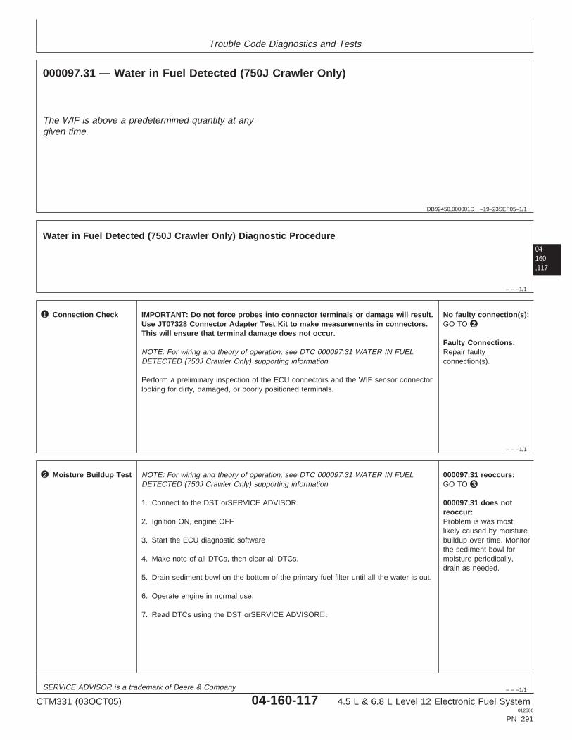
Trouble Code Diagnostics and Tests
DB92450,000001D –19–23SEP05–1/1
000097.31 — Water in Fuel Detected (750J Crawler Only)
The WIF is above a predetermined quantity at anygiven time.
04160,117
– – –1/1
Water in Fuel Detected (750J Crawler Only) Diagnostic Procedure
– – –1/1
1 Connection Check IMPORTANT: Do not force probes into connector terminals or damage will result.Use JT07328 Connector Adapter Test Kit to make measurements in connectors.This will ensure that terminal damage does not occur.
NOTE: For wiring and theory of operation, see DTC 000097.31 WATER IN FUELDETECTED (750J Crawler Only) supporting information.
Perform a preliminary inspection of the ECU connectors and the WIF sensor connectorlooking for dirty, damaged, or poorly positioned terminals.
No faulty connection(s):GO TO 2
Faulty Connections:Repair faultyconnection(s).
– – –1/1
2 Moisture Buildup Test NOTE: For wiring and theory of operation, see DTC 000097.31 WATER IN FUELDETECTED (750J Crawler Only) supporting information.
1. Connect to the DST orSERVICE ADVISOR.
2. Ignition ON, engine OFF
3. Start the ECU diagnostic software
4. Make note of all DTCs, then clear all DTCs.
5. Drain sediment bowl on the bottom of the primary fuel filter until all the water is out.
6. Operate engine in normal use.
7. Read DTCs using the DST orSERVICE ADVISOR.
000097.31 reoccurs:GO TO 3
000097.31 does notreoccur:Problem is was mostlikely caused by moisturebuildup over time. Monitorthe sediment bowl formoisture periodically,drain as needed.
SERVICE ADVISOR is a trademark of Deere & Company
CTM331 (03OCT05) 04-160-117 4.5 L & 6.8 L Level 12 Electronic Fuel System012506
PN=291
Trouble Code Diagnostics and Tests
– – –1/1
3 WIF Circuit andSensor Test
NOTE: For wiring and theory of operation, see DTC 000097.31 WATER IN FUELDETECTED (750J Crawler Only) supporting information.
Check the following items that can cause water in the fuel:
• Poor fuel quality or water in fuel storage tank.• Loose fuel tank cap.• Missing or damaged fuel tank cap seal.• Excessive condensation build up in fuel tank.• Loose or damaged fuel filter or sediment bowl.
Cause of water in fuellocated:Repair problem, drainsediment bowl, andretest.
No cause of water infuel located:Verify that WIF sensorinput and ground circuitsare OK.If WIF sensor circuits areOK, replace WIF sensorand retest.
04160,118
CTM331 (03OCT05) 04-160-118 4.5 L & 6.8 L Level 12 Electronic Fuel System012506
PN=292

Trouble Code Diagnostics and Tests
04160,119
CTM331 (03OCT05) 04-160-119 4.5 L & 6.8 L Level 12 Electronic Fuel System012506
PN=293
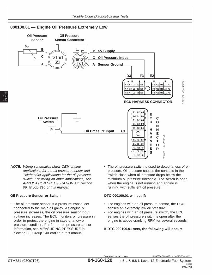
Trouble Code Diagnostics and Tests
04160,120
RG40854,0000088 –19–07DEC01–1/2
000100.01 — Engine Oil Pressure Extremely Low
A1
A2
A3 B3 C3 D3 E3
B2 C2 D2 E2
B1 C1 D1 E1 F1
F2
F3 G3 H3 J3 K3
G2 H2 J2 K2
G1 H1 J1 K1
ECU HARNESS CONNECTOR
Oil PressureSensor Connector
Oil PressureSensor
BC
AA
C
B
B
C
A
D3 F3 E2
B 5V Supply
C Oil Pressure Input
A Sensor Ground
RG
1197
8–1
9–14
DE
C01
Oil PressureSwitch
Oil Pressure Input C1P
A1 A2 A3
B3
C3
D3
E3
B2
C2
D2
E2
B1
C1
D1
E1
F1 F2 F3
G3
H3
J3
K3
G2
H2
J2
K2
G1
H1
J1
K1
ECU
HARNESS
CONNECTOR
RG
1204
5–1
9–20
DE
C01
NOTE: Wiring schematics show OEM engineapplications for the oil pressure sensor andTelehandler applications for the oil pressureswitch. For wiring on other applications, seeAPPLICATION SPECIFICATIONS in Section06, Group 210 of this manual.
Oil Pressure Sensor or Switch
• The oil pressure sensor is a pressure transducerconnected to the main oil galley. As engine oilpressure increases, the oil pressure sensor inputvoltage increases. The ECU monitors oil pressure inorder to protect the engine in case of a low oilpressure condition. For further oil pressure sensorinformation, see MEASURING PRESSURE inSection 03, Group 140 earlier in this manual.
• The oil pressure switch is used to detect a loss of oilpressure. Oil pressure causes the contacts in theswitch close when oil pressure drops below theminimum oil pressure threshold. The switch is openwhen the engine is not running and engine isrunning with sufficient oil pressure.
DTC 000100.01 will set if:
• For engines with an oil pressure sensor, the ECUsenses an extremely low oil pressure.
• For engines with an oil pressure switch, the ECUsenses the oil pressure switch is open after theengine is above cranking RPM for several seconds.
If DTC 000100.01 sets, the following will occur:
CTM331 (03OCT05) 04-160-120 4.5 L & 6.8 L Level 12 Electronic Fuel System012506
PN=294
Continued on next page
Trouble Code Diagnostics and Tests
RG40854,0000088 –19–07DEC01–2/2
• Engine protection is enabled. See ENGINEPROTECTION in Section 03, Group 140 of thismanual.– With Shutdown Feature: The derate feature will go
into effect when the code is set, and the enginewill shut down after 30 seconds.
– With Derate Feature: On OEM applications, theengine derates 60% per minute until the engine isrunning at 40% of full power. For non-OEMapplications, see APPLICATIONSPECIFICATIONS in Section 06, Group 210 ofthis manual.
04160,121
CTM331 (03OCT05) 04-160-121 4.5 L & 6.8 L Level 12 Electronic Fuel System012506
PN=295
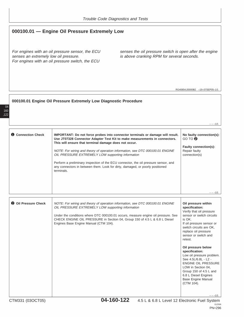
Trouble Code Diagnostics and Tests
RG40854,00000B2 –19–07SEP05–1/1
000100.01 — Engine Oil Pressure Extremely Low
For engines with an oil pressure sensor, the ECUsenses an extremely low oil pressure.For engines with an oil pressure switch, the ECU
senses the oil pressure switch is open after the engineis above cranking RPM for several seconds.
04160,122
– – –1/1
000100.01 Engine Oil Pressure Extremely Low Diagnostic Procedure
– – –1/1
1 Connection Check IMPORTANT: Do not force probes into connector terminals or damage will result.Use JT07328 Connector Adapter Test Kit to make measurements in connectors.This will ensure that terminal damage does not occur.
NOTE: For wiring and theory of operation information, see DTC 000100.01 ENGINEOIL PRESSURE EXTREMELY LOW supporting information
Perform a preliminary inspection of the ECU connector, the oil pressure sensor, andany connectors in between them. Look for dirty, damaged, or poorly positionedterminals.
No faulty connection(s):GO TO 2
Faulty connection(s):Repair faultyconnection(s)
– – –1/1
2 Oil Pressure Check NOTE: For wiring and theory of operation information, see DTC 000100.01 ENGINEOIL PRESSURE EXTREMELY LOW supporting information
Under the conditions where DTC 000100.01 occurs, measure engine oil pressure. SeeCHECK ENGINE OIL PRESSURE in Section 04, Group 150 of 4.5 L & 6.8 L DieselEngines Base Engine Manual (CTM 104).
Oil pressure withinspecification:Verify that oil pressuresensor or switch circuitsis OK.If oil pressure sensor orswitch circuits are OK,replace oil pressuresensor or switch andretest.
Oil pressure belowspecification:Low oil pressure problem.See 4.5L/6.8L - L2 -ENGINE OIL PRESSURELOW in Section 04,Group 150 of 4.5 L and6.8 L Diesel EnginesBase Engine Manual(CTM 104).
CTM331 (03OCT05) 04-160-122 4.5 L & 6.8 L Level 12 Electronic Fuel System012506
PN=296

Trouble Code Diagnostics and Tests
04160,123
CTM331 (03OCT05) 04-160-123 4.5 L & 6.8 L Level 12 Electronic Fuel System012506
PN=297
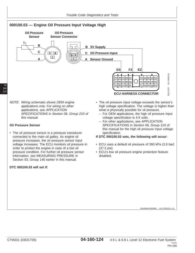
Trouble Code Diagnostics and Tests
04160,124
RG40854,0000086 –19–07DEC01–1/1
000100.03 — Engine Oil Pressure Input Voltage High
A1
A2
A3 B3 C3 D3 E3
B2 C2 D2 E2
B1 C1 D1 E1 F1
F2
F3 G3 H3 J3 K3
G2 H2 J2 K2
G1 H1 J1 K1
ECU HARNESS CONNECTOR
Oil PressureSensor Connector
Oil PressureSensor
BC
AA
C
B
B
C
A
D3 F3 E2
B 5V Supply
C Oil Pressure Input
A Sensor Ground
RG
1197
8–1
9–14
DE
C01
NOTE: Wiring schematic shows OEM engineapplications only. For wiring on otherapplications, see APPLICATIONSPECIFICATIONS in Section 06, Group 210 ofthis manual.
Oil Pressure Sensor
• The oil pressure sensor is a pressure transducerconnected to the main oil galley. As engine oilpressure increases, the oil pressure sensor inputvoltage increases. The ECU monitors oil pressure inorder to protect the engine in case of a low oilpressure condition. For further oil pressure sensorinformation, see MEASURING PRESSURE inSection 03, Group 140 earlier in this manual.
DTC 000100.03 will set if:
• The oil pressure input voltage exceeds the sensor’shigh voltage specification. The voltage is higher thanwhat is physically possible for oil pressure.– For OEM applications, the high oil pressure input
voltage specification is 4.5 volts.– For other applications, see APPLICATION
SPECIFICATIONS in Section 06, Group 210 ofthis manual for the high oil pressure input voltagespecification.
If DTC 000100.03 sets, the following will occur:
• ECU uses a default oil pressure of 260 kPa (2.6 bar)(37.5 psi).
• ECU’s low oil pressure engine protection featuredisabled.
CTM331 (03OCT05) 04-160-124 4.5 L & 6.8 L Level 12 Electronic Fuel System012506
PN=298
Trouble Code Diagnostics and Tests
RG40854,00000B3 –19–19SEP05–1/1
000100.03 — Engine Oil Pressure Input Voltage High
The oil pressure input voltage exceeds the sensor’shigh voltage specification. The voltage is higher thanwhat is physically possible for oil pressure.
04160,125
– – –1/1
000100.03 Engine Oil Pressure Input Voltage High Diagnostic Procedure
– – –1/1
1 Connection Check IMPORTANT: Do not force probes into connector terminals or damage will result.Use JT07328 Connector Adapter Test Kit to make measurements in connectors.This will ensure that terminal damage does not occur.
NOTE: For wiring and theory of operation information, see DTC 000100.03 ENGINEOIL PRESSURE INPUT VOLTAGE HIGH supporting information
Perform a preliminary inspection of the ECU connector, the oil pressure sensorconnector, and any connectors in between them. Look for dirty, damaged, or poorlypositioned terminals.
No faulty connection(s):GO TO 2
Faulty connection(s):Repair faultyconnection(s)
– – –1/1
2 Intermittent Fault Test NOTE: For wiring and theory of operation information, see DTC 000100.03 ENGINEOIL PRESSURE INPUT VOLTAGE HIGH supporting information
1. Connect to the DST or SERVICE ADVISOR.
2. Ignition ON, engine OFF
3. Start the ECU communication software
4. Read DTCs using the DST orSERVICE ADVISOR.
5. Make note of any DTCs, then clear all DTCs
6. Ignition ON, engine running
7. Read Oil Pressure Input Voltage using the the DST orSERVICE ADVISOR.
NOTE: For OEM applications, the high oil pressure input voltage specification is4.5V. For the high voltage specification on other applications, see APPLICATIONSPECIFICATIONS in Section 06, Group 210 of this manual.
4.5 V or greater:GO TO 3
Below 4.5 V:Problem is intermittent. Ifno other codes arepresent, seeINTERMITTENT FAULTDIAGNOSTICS, earlier inthis Group.
SERVICE ADVISOR is a trademark of Deere & Company
CTM331 (03OCT05) 04-160-125 4.5 L & 6.8 L Level 12 Electronic Fuel System012506
PN=299
Trouble Code Diagnostics and Tests
– – –1/1
3 Oil Pressure InputShorted Test
NOTE: For wiring and theory of operation information, see DTC 000100.03 ENGINEOIL PRESSURE INPUT VOLTAGE HIGH supporting information
1. Ignition OFF
2. Disconnect oil pressure sensor connector
3. Ignition ON, engine OFF
4. Read Oil Pressure Input Voltage using the DST or SERVICE ADVISOR.
NOTE: For OEM applications, the low oil pressure input voltage specification is0.3V. For the low voltage specification on other applications, see APPLICATIONSPECIFICATIONS in Section 06, Group 210 of this manual.
0.3 V or below:GO TO 4
Above 0.3 V:Short to voltage in oilpressure sensor inputcircuitORFaulty ECU
04160,126
– – –1/1
4 Oil Pressure GroundCircuit Open Test
NOTE: For wiring and theory of operation information, see DTC 000100.03 ENGINEOIL PRESSURE INPUT VOLTAGE HIGH supporting information
Probe oil pressure sensor ground (Terminal A) in sensor harness connector with a testlight connected to battery voltage.
Light ON:Faulty oil pressure sensorORFaulty ECU connectionORFaulty ECU
Light OFF:Open in oil pressuresensor ground circuitORFaulty ECU connectionORFaulty ECU
CTM331 (03OCT05) 04-160-126 4.5 L & 6.8 L Level 12 Electronic Fuel System012506
PN=300

Trouble Code Diagnostics and Tests
04160,127
CTM331 (03OCT05) 04-160-127 4.5 L & 6.8 L Level 12 Electronic Fuel System012506
PN=301
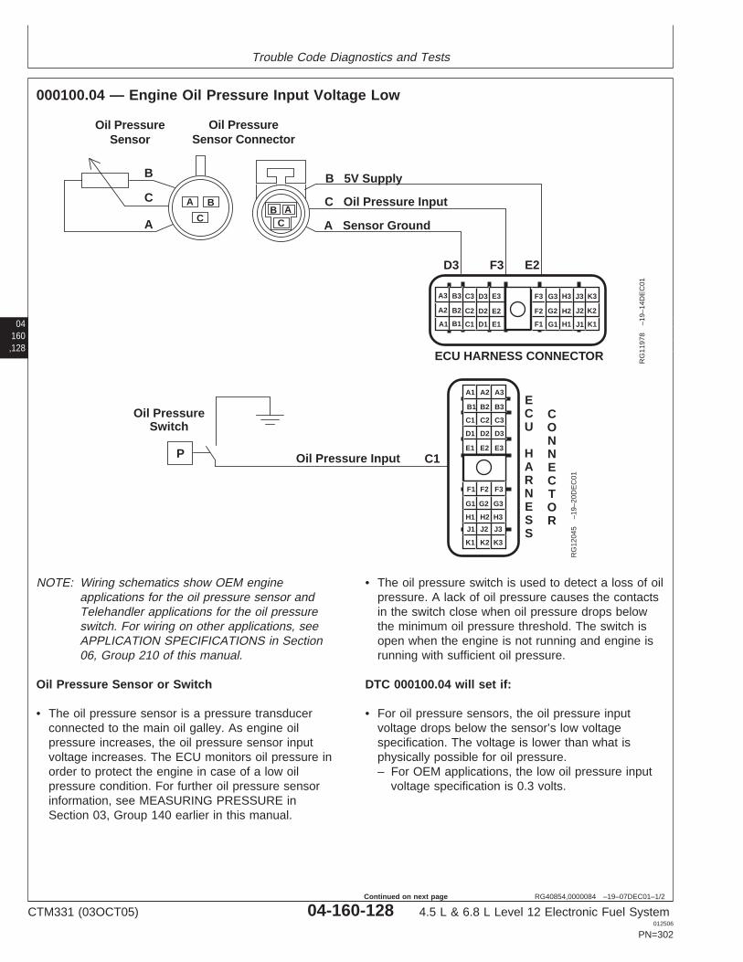
Trouble Code Diagnostics and Tests
04160,128
RG40854,0000084 –19–07DEC01–1/2
000100.04 — Engine Oil Pressure Input Voltage Low
A1
A2
A3 B3 C3 D3 E3
B2 C2 D2 E2
B1 C1 D1 E1 F1
F2
F3 G3 H3 J3 K3
G2 H2 J2 K2
G1 H1 J1 K1
ECU HARNESS CONNECTOR
Oil PressureSensor Connector
Oil PressureSensor
BC
AA
C
B
B
C
A
D3 F3 E2
B 5V Supply
C Oil Pressure Input
A Sensor Ground
RG
1197
8–1
9–14
DE
C01
Oil PressureSwitch
Oil Pressure Input C1P
A1 A2 A3
B3
C3
D3
E3
B2
C2
D2
E2
B1
C1
D1
E1
F1 F2 F3
G3
H3
J3
K3
G2
H2
J2
K2
G1
H1
J1
K1
ECU
HARNESS
CONNECTOR
RG
1204
5–1
9–20
DE
C01
NOTE: Wiring schematics show OEM engineapplications for the oil pressure sensor andTelehandler applications for the oil pressureswitch. For wiring on other applications, seeAPPLICATION SPECIFICATIONS in Section06, Group 210 of this manual.
Oil Pressure Sensor or Switch
• The oil pressure sensor is a pressure transducerconnected to the main oil galley. As engine oilpressure increases, the oil pressure sensor inputvoltage increases. The ECU monitors oil pressure inorder to protect the engine in case of a low oilpressure condition. For further oil pressure sensorinformation, see MEASURING PRESSURE inSection 03, Group 140 earlier in this manual.
• The oil pressure switch is used to detect a loss of oilpressure. A lack of oil pressure causes the contactsin the switch close when oil pressure drops belowthe minimum oil pressure threshold. The switch isopen when the engine is not running and engine isrunning with sufficient oil pressure.
DTC 000100.04 will set if:
• For oil pressure sensors, the oil pressure inputvoltage drops below the sensor’s low voltagespecification. The voltage is lower than what isphysically possible for oil pressure.– For OEM applications, the low oil pressure input
voltage specification is 0.3 volts.
CTM331 (03OCT05) 04-160-128 4.5 L & 6.8 L Level 12 Electronic Fuel System012506
PN=302
Continued on next page
Trouble Code Diagnostics and Tests
RG40854,0000084 –19–07DEC01–2/2
– For other applications, see APPLICATIONSPECIFICATIONS in Section 06, Group 210 ofthis manual for the low oil pressure input voltagespecification.
• For oil pressure switches, the oil pressure switch isclosed when key is on and there is no engine speed.
If DTC 000100.04 sets, the following will occur:
• ECU uses a default oil pressure of 260 kPa (2.6 bar)(37.5 psi).
• ECU’s low oil pressure engine protection featuredisabled.
04160,129
CTM331 (03OCT05) 04-160-129 4.5 L & 6.8 L Level 12 Electronic Fuel System012506
PN=303
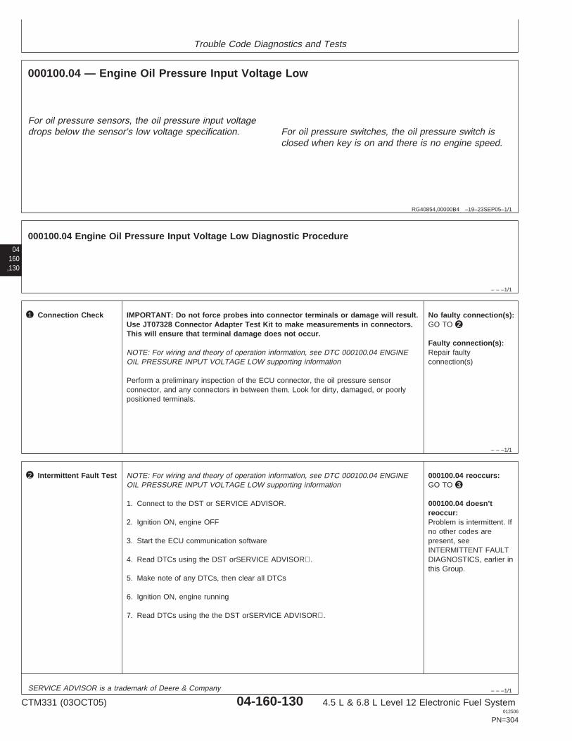
Trouble Code Diagnostics and Tests
RG40854,00000B4 –19–23SEP05–1/1
000100.04 — Engine Oil Pressure Input Voltage Low
For oil pressure sensors, the oil pressure input voltagedrops below the sensor’s low voltage specification. For oil pressure switches, the oil pressure switch is
closed when key is on and there is no engine speed.
04160,130
– – –1/1
000100.04 Engine Oil Pressure Input Voltage Low Diagnostic Procedure
– – –1/1
1 Connection Check IMPORTANT: Do not force probes into connector terminals or damage will result.Use JT07328 Connector Adapter Test Kit to make measurements in connectors.This will ensure that terminal damage does not occur.
NOTE: For wiring and theory of operation information, see DTC 000100.04 ENGINEOIL PRESSURE INPUT VOLTAGE LOW supporting information
Perform a preliminary inspection of the ECU connector, the oil pressure sensorconnector, and any connectors in between them. Look for dirty, damaged, or poorlypositioned terminals.
No faulty connection(s):GO TO 2
Faulty connection(s):Repair faultyconnection(s)
– – –1/1
2 Intermittent Fault Test NOTE: For wiring and theory of operation information, see DTC 000100.04 ENGINEOIL PRESSURE INPUT VOLTAGE LOW supporting information
1. Connect to the DST or SERVICE ADVISOR.
2. Ignition ON, engine OFF
3. Start the ECU communication software
4. Read DTCs using the DST orSERVICE ADVISOR.
5. Make note of any DTCs, then clear all DTCs
6. Ignition ON, engine running
7. Read DTCs using the the DST orSERVICE ADVISOR.
000100.04 reoccurs:GO TO 3
000100.04 doesn’treoccur:Problem is intermittent. Ifno other codes arepresent, seeINTERMITTENT FAULTDIAGNOSTICS, earlier inthis Group.
SERVICE ADVISOR is a trademark of Deere & Company
CTM331 (03OCT05) 04-160-130 4.5 L & 6.8 L Level 12 Electronic Fuel System012506
PN=304
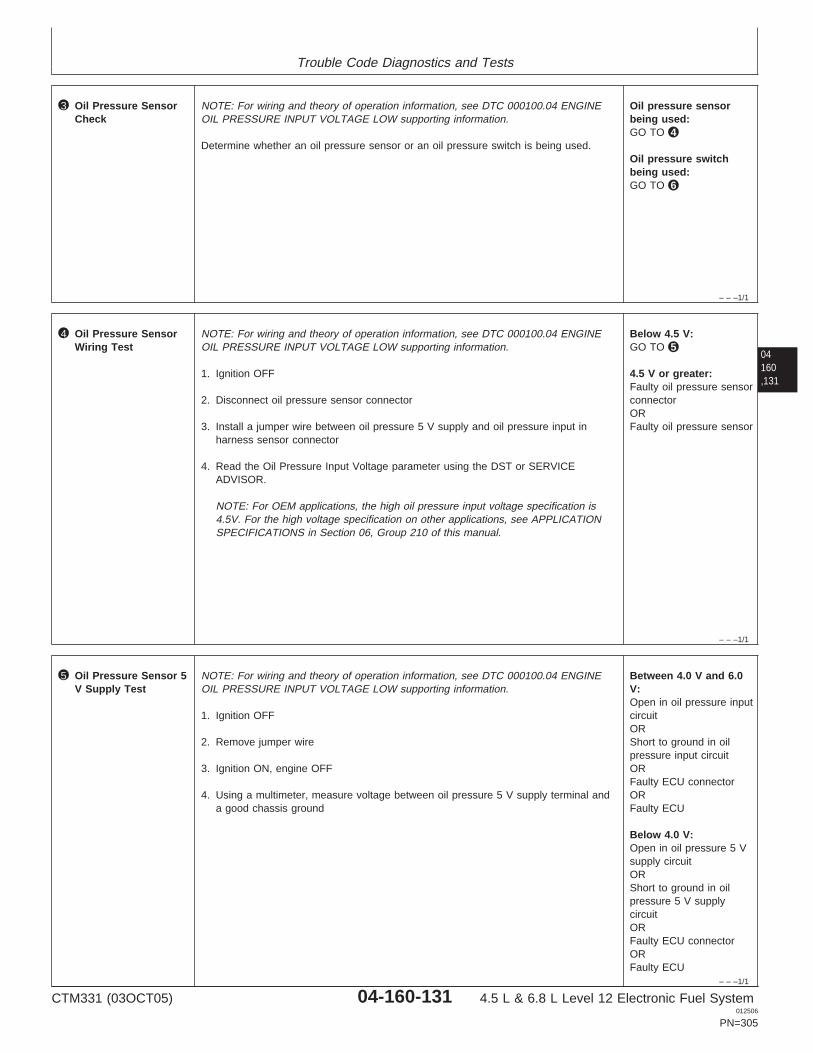
Trouble Code Diagnostics and Tests
– – –1/1
3 Oil Pressure SensorCheck
NOTE: For wiring and theory of operation information, see DTC 000100.04 ENGINEOIL PRESSURE INPUT VOLTAGE LOW supporting information.
Determine whether an oil pressure sensor or an oil pressure switch is being used.
Oil pressure sensorbeing used:GO TO 4
Oil pressure switchbeing used:GO TO 6
04160,131
– – –1/1
4 Oil Pressure SensorWiring Test
NOTE: For wiring and theory of operation information, see DTC 000100.04 ENGINEOIL PRESSURE INPUT VOLTAGE LOW supporting information.
1. Ignition OFF
2. Disconnect oil pressure sensor connector
3. Install a jumper wire between oil pressure 5 V supply and oil pressure input inharness sensor connector
4. Read the Oil Pressure Input Voltage parameter using the DST or SERVICEADVISOR.
NOTE: For OEM applications, the high oil pressure input voltage specification is4.5V. For the high voltage specification on other applications, see APPLICATIONSPECIFICATIONS in Section 06, Group 210 of this manual.
Below 4.5 V:GO TO 5
4.5 V or greater:Faulty oil pressure sensorconnectorORFaulty oil pressure sensor
– – –1/1
5 Oil Pressure Sensor 5V Supply Test
NOTE: For wiring and theory of operation information, see DTC 000100.04 ENGINEOIL PRESSURE INPUT VOLTAGE LOW supporting information.
1. Ignition OFF
2. Remove jumper wire
3. Ignition ON, engine OFF
4. Using a multimeter, measure voltage between oil pressure 5 V supply terminal anda good chassis ground
Between 4.0 V and 6.0V:Open in oil pressure inputcircuitORShort to ground in oilpressure input circuitORFaulty ECU connectorORFaulty ECU
Below 4.0 V:Open in oil pressure 5 Vsupply circuitORShort to ground in oilpressure 5 V supplycircuitORFaulty ECU connectorORFaulty ECU
CTM331 (03OCT05) 04-160-131 4.5 L & 6.8 L Level 12 Electronic Fuel System012506
PN=305
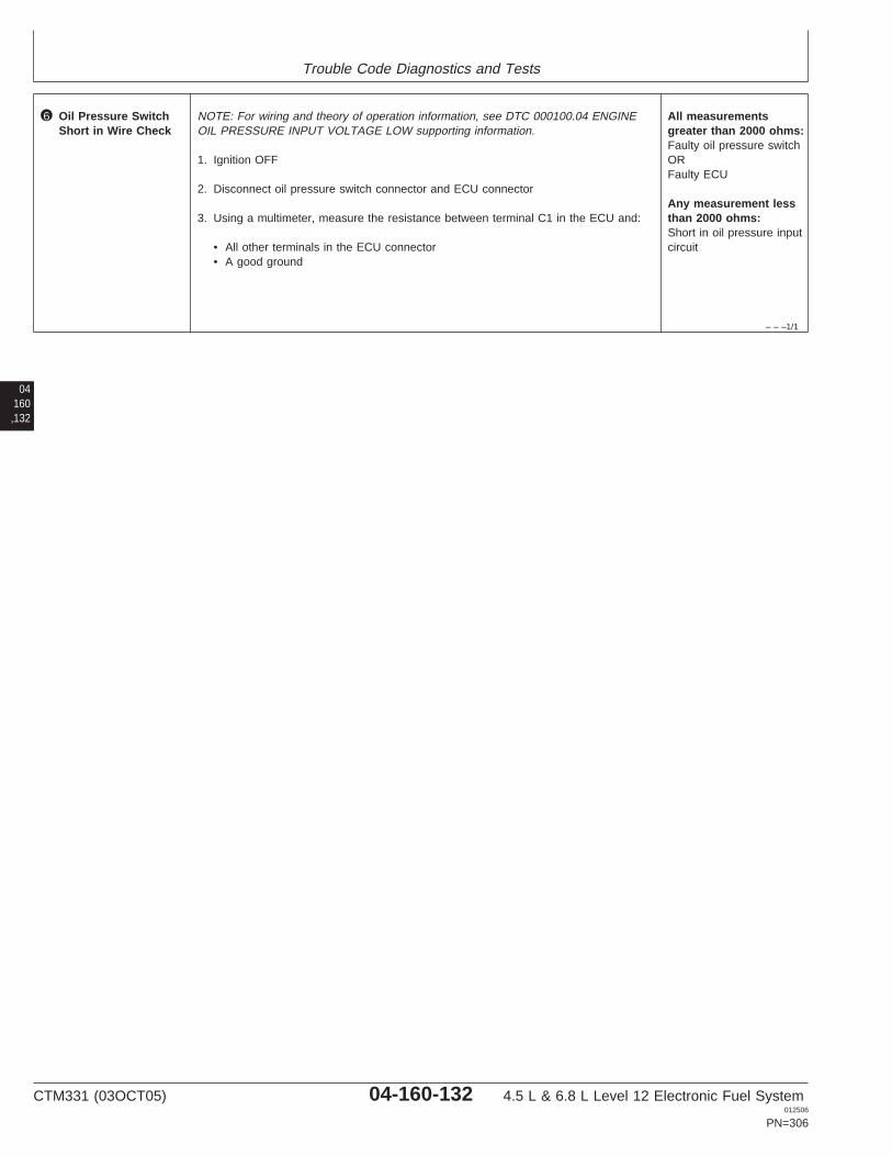
Trouble Code Diagnostics and Tests
– – –1/1
6 Oil Pressure SwitchShort in Wire Check
NOTE: For wiring and theory of operation information, see DTC 000100.04 ENGINEOIL PRESSURE INPUT VOLTAGE LOW supporting information.
1. Ignition OFF
2. Disconnect oil pressure switch connector and ECU connector
3. Using a multimeter, measure the resistance between terminal C1 in the ECU and:
• All other terminals in the ECU connector• A good ground
All measurementsgreater than 2000 ohms:Faulty oil pressure switchORFaulty ECU
Any measurement lessthan 2000 ohms:Short in oil pressure inputcircuit
04160,132
CTM331 (03OCT05) 04-160-132 4.5 L & 6.8 L Level 12 Electronic Fuel System012506
PN=306

Trouble Code Diagnostics and Tests
04160,133
CTM331 (03OCT05) 04-160-133 4.5 L & 6.8 L Level 12 Electronic Fuel System012506
PN=307
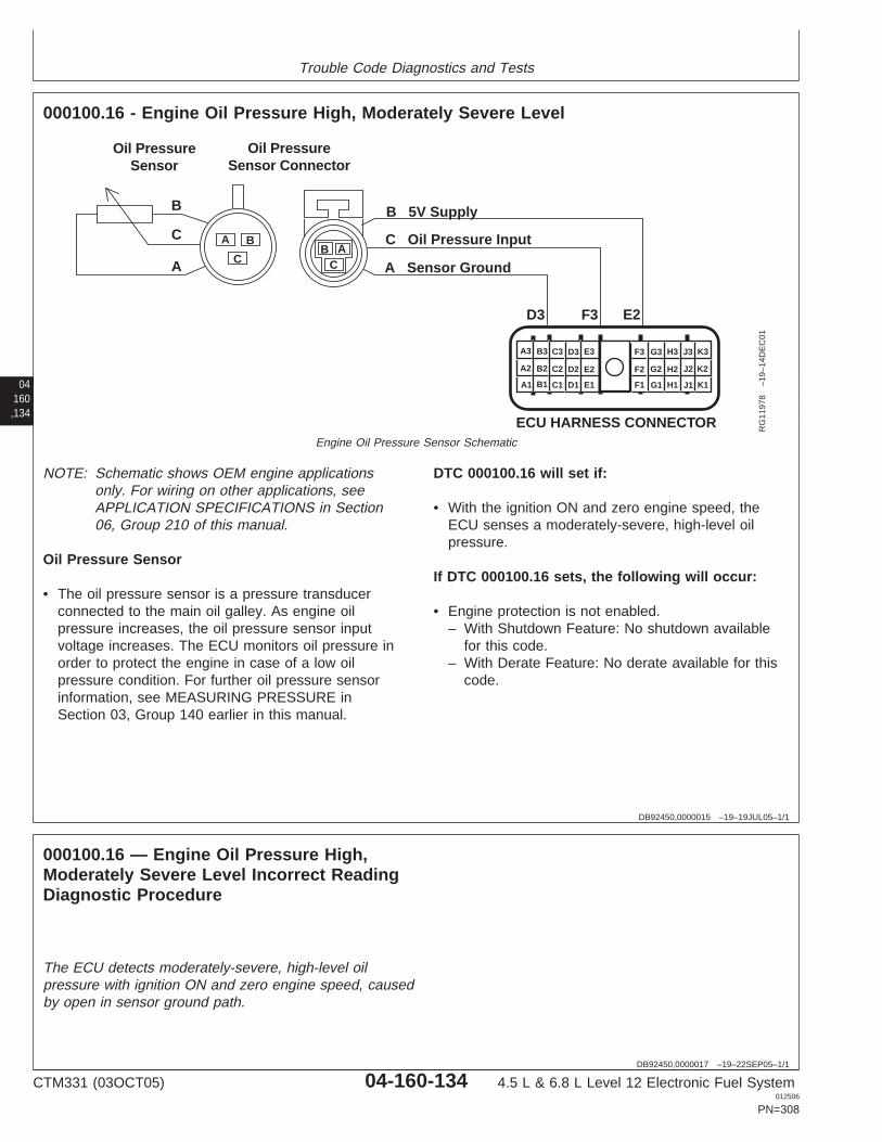
Trouble Code Diagnostics and Tests
04160,134
DB92450,0000015 –19–19JUL05–1/1
000100.16 - Engine Oil Pressure High, Moderately Severe Level
A1
A2
A3 B3 C3 D3 E3
B2 C2 D2 E2
B1 C1 D1 E1 F1
F2
F3 G3 H3 J3 K3
G2 H2 J2 K2
G1 H1 J1 K1
ECU HARNESS CONNECTOR
Oil PressureSensor Connector
Oil PressureSensor
BC
AA
C
B
B
C
A
D3 F3 E2
B 5V Supply
C Oil Pressure Input
A Sensor Ground
RG
1197
8–1
9–14
DE
C01
Engine Oil Pressure Sensor Schematic
NOTE: Schematic shows OEM engine applicationsonly. For wiring on other applications, seeAPPLICATION SPECIFICATIONS in Section06, Group 210 of this manual.
Oil Pressure Sensor
• The oil pressure sensor is a pressure transducerconnected to the main oil galley. As engine oilpressure increases, the oil pressure sensor inputvoltage increases. The ECU monitors oil pressure inorder to protect the engine in case of a low oilpressure condition. For further oil pressure sensorinformation, see MEASURING PRESSURE inSection 03, Group 140 earlier in this manual.
DTC 000100.16 will set if:
• With the ignition ON and zero engine speed, theECU senses a moderately-severe, high-level oilpressure.
If DTC 000100.16 sets, the following will occur:
• Engine protection is not enabled.– With Shutdown Feature: No shutdown available
for this code.– With Derate Feature: No derate available for this
code.
DB92450,0000017 –19–22SEP05–1/1
000100.16 — Engine Oil Pressure High,Moderately Severe Level Incorrect ReadingDiagnostic Procedure
The ECU detects moderately-severe, high-level oilpressure with ignition ON and zero engine speed, causedby open in sensor ground path.
CTM331 (03OCT05) 04-160-134 4.5 L & 6.8 L Level 12 Electronic Fuel System012506
PN=308
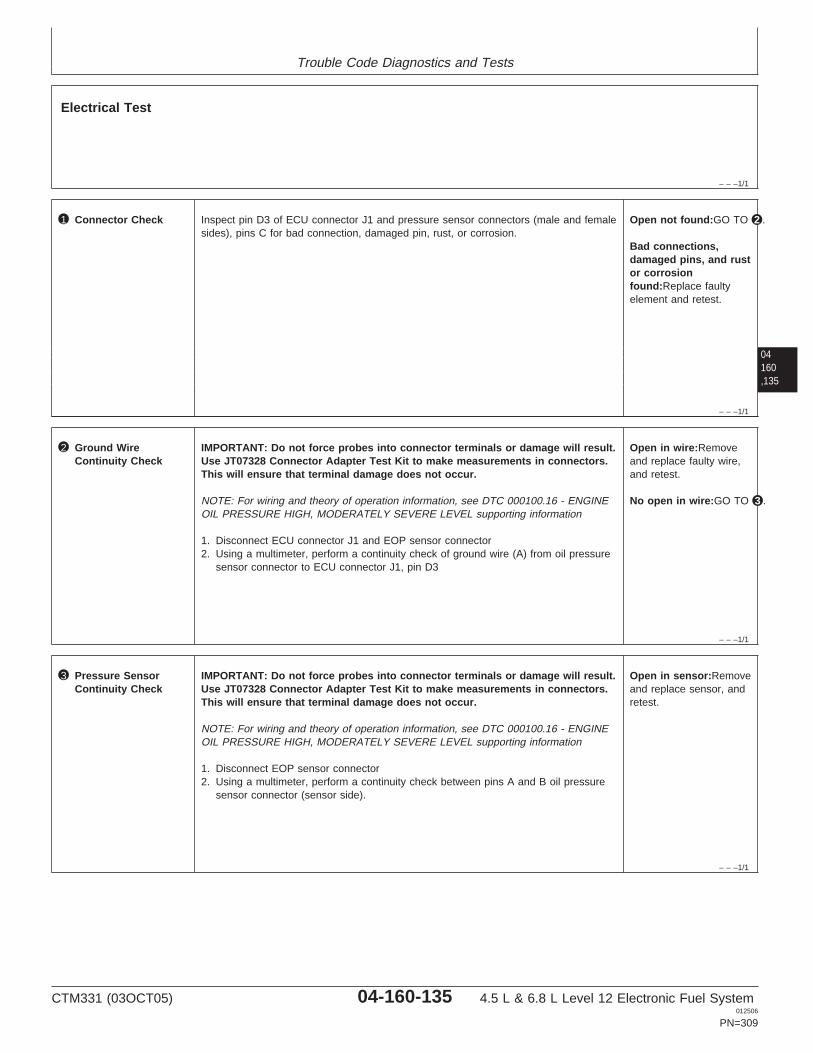
Trouble Code Diagnostics and Tests
– – –1/1
Electrical Test
04160,135
– – –1/1
1 Connector Check Inspect pin D3 of ECU connector J1 and pressure sensor connectors (male and femalesides), pins C for bad connection, damaged pin, rust, or corrosion.
Open not found:GO TO 2 .
Bad connections,damaged pins, and rustor corrosionfound:Replace faultyelement and retest.
– – –1/1
2 Ground WireContinuity Check
IMPORTANT: Do not force probes into connector terminals or damage will result.Use JT07328 Connector Adapter Test Kit to make measurements in connectors.This will ensure that terminal damage does not occur.
NOTE: For wiring and theory of operation information, see DTC 000100.16 - ENGINEOIL PRESSURE HIGH, MODERATELY SEVERE LEVEL supporting information
1. Disconnect ECU connector J1 and EOP sensor connector2. Using a multimeter, perform a continuity check of ground wire (A) from oil pressure
sensor connector to ECU connector J1, pin D3
Open in wire:Removeand replace faulty wire,and retest.
No open in wire:GO TO 3 .
– – –1/1
3 Pressure SensorContinuity Check
IMPORTANT: Do not force probes into connector terminals or damage will result.Use JT07328 Connector Adapter Test Kit to make measurements in connectors.This will ensure that terminal damage does not occur.
NOTE: For wiring and theory of operation information, see DTC 000100.16 - ENGINEOIL PRESSURE HIGH, MODERATELY SEVERE LEVEL supporting information
1. Disconnect EOP sensor connector2. Using a multimeter, perform a continuity check between pins A and B oil pressure
sensor connector (sensor side).
Open in sensor:Removeand replace sensor, andretest.
CTM331 (03OCT05) 04-160-135 4.5 L & 6.8 L Level 12 Electronic Fuel System012506
PN=309
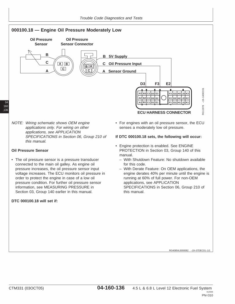
Trouble Code Diagnostics and Tests
04160,136
RG40854,0000082 –19–07DEC01–1/1
000100.18 — Engine Oil Pressure Moderately Low
A1
A2
A3 B3 C3 D3 E3
B2 C2 D2 E2
B1 C1 D1 E1 F1
F2
F3 G3 H3 J3 K3
G2 H2 J2 K2
G1 H1 J1 K1
ECU HARNESS CONNECTOR
Oil PressureSensor Connector
Oil PressureSensor
BC
AA
C
B
B
C
A
D3 F3 E2
B 5V Supply
C Oil Pressure Input
A Sensor Ground
RG
1197
8–1
9–14
DE
C01
NOTE: Wiring schematic shows OEM engineapplications only. For wiring on otherapplications, see APPLICATIONSPECIFICATIONS in Section 06, Group 210 ofthis manual.
Oil Pressure Sensor
• The oil pressure sensor is a pressure transducerconnected to the main oil galley. As engine oilpressure increases, the oil pressure sensor inputvoltage increases. The ECU monitors oil pressure inorder to protect the engine in case of a low oilpressure condition. For further oil pressure sensorinformation, see MEASURING PRESSURE inSection 03, Group 140 earlier in this manual.
DTC 000100.18 will set if:
• For engines with an oil pressure sensor, the ECUsenses a moderately low oil pressure.
If DTC 000100.18 sets, the following will occur:
• Engine protection is enabled. See ENGINEPROTECTION in Section 03, Group 140 of thismanual.– With Shutdown Feature: No shutdown available
for this code.– With Derate Feature: On OEM applications, the
engine derates 40% per minute until the engine isrunning at 60% of full power. For non-OEMapplications, see APPLICATIONSPECIFICATIONS in Section 06, Group 210 ofthis manual.
CTM331 (03OCT05) 04-160-136 4.5 L & 6.8 L Level 12 Electronic Fuel System012506
PN=310
Trouble Code Diagnostics and Tests
RG40854,00000B5 –19–07SEP05–1/1
000100.18 — Engine Oil Pressure Moderately Low
For engines with an oil pressure sensor, the ECUsenses a moderately low oil pressure.
04160,137
– – –1/1
000100.18 Engine Oil Pressure Moderately Low Diagnostic Procedure
– – –1/1
1 Connection Check IMPORTANT: Do not force probes into connector terminals or damage will result.Use JT07328 Connector Adapter Test Kit to make measurements in connectors.This will ensure that terminal damage does not occur.
NOTE: For wiring and theory of operation information, see DTC 000100.18 ENGINEOIL PRESSURE MODERATELY LOW supporting information
Perform a preliminary inspection of the ECU connector, the oil pressure sensorconnector, and any connectors in between them. Look for dirty, damaged, or poorlypositioned terminals.
No faulty connection(s):GO TO 2
Faulty connection(s):Repair faultyconnection(s)
– – –1/1
2 Oil Pressure Check NOTE: For wiring and theory of operation information, see DTC 000100.18 ENGINEOIL PRESSURE MODERATELY LOW supporting information
Under the conditions where DTC 000100.18 occurs, measure engine oil pressure.CHECK ENGINE OIL PRESSURE in Section 04, Group 150 of 4.5 L & 6.8 L DieselEngines Base Engine Manual (CTM 104).
Oil pressure withinspecification:Low oil pressure problem.See 4.5L/6.8L - L2 -ENGINE OIL PRESSURELOW in Section 04,Group 150 of 4.5 L and6.8 L Diesel EnginesBase Engine Manual(CTM 104).
Oil pressure belowspecification:Verify that oil pressuresensor 5 V supply, input,and ground circuits areOK.If oil pressure sensorcircuits are OK, replaceoil pressure sensor andretest.
CTM331 (03OCT05) 04-160-137 4.5 L & 6.8 L Level 12 Electronic Fuel System012506
PN=311

Trouble Code Diagnostics and Tests
04160,138
RG40854,0000080 –19–07DEC01–1/1
000105.03 — Manifold Air Temperature Input Voltage High
D1
A A
BB
D3
MAT SensorConnector
Sensor Ground
MAT Input
MAT Sensor
t
A1
A2
A3 B3 C3 D3 E3
B2 C2 D2 E2
B1 C1 D1 E1 F1
F2
F3 G3 H3 J3 K3
G2 H2 J2 K2
G1 H1 J1 K1
ECU HARNESS CONNECTOR RG
1197
9–1
9–14
DE
C01
NOTE: Wiring schematic shows OEM engineapplications only. For wiring on otherapplications, see APPLICATIONSPECIFICATIONS in Section 06, Group 210 ofthis manual.
MAT (Manifold Air Temperature) Sensor
• The MAT sensor is a thermistor (temperaturesensitive resistor) mounted in the intake manifold.The MAT sensor is used to measure thetemperature of the intake air. The MAT sensor’svariable resistance causes the input voltage to theECU to vary. Higher intake air temperatures result inlower MAT input voltages to the ECU; lowertemperatures result in higher voltages. For furtherMAT sensor information, see MEASURINGTEMPERATURE in Section 03, Group 140.
DTC 000105.03 will set if:
• The manifold air temperature input voltage exceedsthe sensor’s high voltage specification. The voltageis higher than what is physically possible formanifold air.– For OEM applications, the high manifold air
temperature input voltage specification is 4.9volts.
– For other applications, see APPLICATIONSPECIFICATIONS in Section 06, Group 210 ofthis manual for the high manifold air temperaturespecification.
If DTC 000105.03 sets, the following will occur:
• ECU uses a default MAT value of 60°C (140°F).• ECU’s high manifold air temperature engine
protection feature disabled.
CTM331 (03OCT05) 04-160-138 4.5 L & 6.8 L Level 12 Electronic Fuel System012506
PN=312

Trouble Code Diagnostics and Tests
RG40854,00000B6 –19–23SEP05–1/1
000105.03 — Manifold Air Temperature Input Voltage High
The manifold air temperature input voltage exceedsthe sensor’s high voltage specification.
04160,139
– – –1/1
000105.03 Manifold Air Temperature Input Voltage High Diagnostic Procedure
– – –1/1
1 Connection Check IMPORTANT: Do not force probes into connector terminals or damage will result.Use JT07328 Connector Adapter Test Kit to make measurements in connectors.This will ensure that terminal damage does not occur.
NOTE: For wiring and theory of operation information, see DTC 000105.03 MANIFOLDAIR TEMPERATURE INPUT VOLTAGE HIGH supporting information.
Perform a preliminary inspection of the ECU connector, the manifold air temperaturesensor connector, and any connectors in between them. Look for dirty, damaged, orpoorly positioned terminals.
No faulty connection(s):GO TO 2
Faulty connection(s):Repair faultyconnection(s)
– – –1/1
2 Intermittent Fault Test NOTE: For wiring and theory of operation information, see DTC 000105.03 MANIFOLDAIR TEMPERATURE INPUT VOLTAGE HIGH supporting information.
1. Connect to the DST or SERVICE ADVISOR.
2. Ignition ON, engine OFF
3. Start the ECU communication software
4. Ignition ON, engine OFF
5. Read the Manifold Air Temperature Input Voltage parameter using the DSTorSERVICE ADVISOR.
NOTE: For OEM applications, the high manifold air temperature input voltagespecification is 4.9V. For the high voltage specification on other applications, seeAPPLICATION SPECIFICATIONS in Section 06, Group 210 of this manual.
4.9 V or greater:GO TO 3
Below 4.9 V:Problem is intermittent. Ifno other codes arepresent, seeINTERMITTENT FAULTDIAGNOSTICS earlier inthis Group.
SERVICE ADVISOR is a trademark of Deere & Company
CTM331 (03OCT05) 04-160-139 4.5 L & 6.8 L Level 12 Electronic Fuel System012506
PN=313
Trouble Code Diagnostics and Tests
04160,140
– – –1/1
3 MAT Sensor andConnector Test
NOTE: For wiring and theory of operation information, see DTC 000105.03 MANIFOLDAIR TEMPERATURE INPUT VOLTAGE HIGH supporting information.
1. Ignition OFF
2. Disconnect MAT sensor connector
3. Install a jumper wire between both terminals in the MAT sensor harness connector
4. Ignition ON, engine OFF
5. Read the Manifold Air Temperature Input Voltage parameter using the DST orSERVICE ADVISOR.
NOTE: For OEM applications, the low manifold air temperature input voltagespecification is 0.1V. For the low voltage specification on other applications, seeAPPLICATION SPECIFICATIONS in Section 06, Group 210 of this manual.
Above 0.1 V:GO TO 4
0.1 V or below:Faulty MAT sensorconnectorORFaulty MAT sensor
– – –1/1
4 MAT Sensor OpenGround Circuit Test
NOTE: For wiring and theory of operation information, see DTC 000105.03 MANIFOLDAIR TEMPERATURE INPUT VOLTAGE HIGH supporting information.
1. Ignition OFF
2. Remove jumper wire between both terminals.
3. Install jumper wire between MAT sensor harness connector input terminal and agood chassis ground.
4. Ignition ON, engine OFF
5. Read the Manifold Air Temperature Input Voltage parameter using the DST orSERVICE ADVISOR.
NOTE: For OEM applications, the low manifold air temperature input voltagespecification is 0.1V. For the low voltage specification on other applications, seeAPPLICATION SPECIFICATIONS in Section 06, Group 210 of this manual.
Above 0.1 V:Open in MAT sensorinput circuitORFaulty ECU connectionORFaulty ECU
0.1 V or below:Open in MAT sensorground circuitORFaulty ECU connectionORFaulty ECU
CTM331 (03OCT05) 04-160-140 4.5 L & 6.8 L Level 12 Electronic Fuel System012506
PN=314

Trouble Code Diagnostics and Tests
04160,141
CTM331 (03OCT05) 04-160-141 4.5 L & 6.8 L Level 12 Electronic Fuel System012506
PN=315
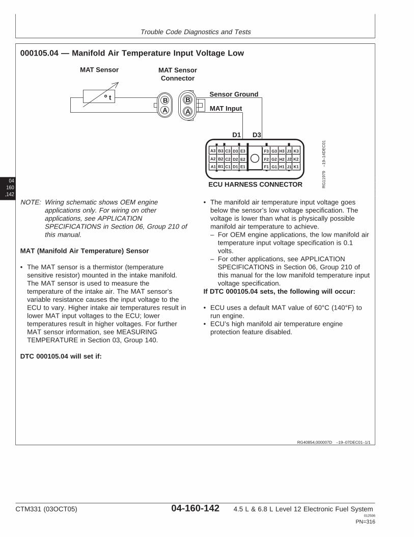
Trouble Code Diagnostics and Tests
04160,142
RG40854,000007D –19–07DEC01–1/1
000105.04 — Manifold Air Temperature Input Voltage Low
D1
A A
BB
D3
MAT SensorConnector
Sensor Ground
MAT Input
MAT Sensor
t
A1
A2
A3 B3 C3 D3 E3
B2 C2 D2 E2
B1 C1 D1 E1 F1
F2
F3 G3 H3 J3 K3
G2 H2 J2 K2
G1 H1 J1 K1
ECU HARNESS CONNECTOR RG
1197
9–1
9–14
DE
C01
NOTE: Wiring schematic shows OEM engineapplications only. For wiring on otherapplications, see APPLICATIONSPECIFICATIONS in Section 06, Group 210 ofthis manual.
MAT (Manifold Air Temperature) Sensor
• The MAT sensor is a thermistor (temperaturesensitive resistor) mounted in the intake manifold.The MAT sensor is used to measure thetemperature of the intake air. The MAT sensor’svariable resistance causes the input voltage to theECU to vary. Higher intake air temperatures result inlower MAT input voltages to the ECU; lowertemperatures result in higher voltages. For furtherMAT sensor information, see MEASURINGTEMPERATURE in Section 03, Group 140.
DTC 000105.04 will set if:
• The manifold air temperature input voltage goesbelow the sensor’s low voltage specification. Thevoltage is lower than what is physically possiblemanifold air temperature to achieve.– For OEM engine applications, the low manifold air
temperature input voltage specification is 0.1volts.
– For other applications, see APPLICATIONSPECIFICATIONS in Section 06, Group 210 ofthis manual for the low manifold temperature inputvoltage specification.
If DTC 000105.04 sets, the following will occur:
• ECU uses a default MAT value of 60°C (140°F) torun engine.
• ECU’s high manifold air temperature engineprotection feature disabled.
CTM331 (03OCT05) 04-160-142 4.5 L & 6.8 L Level 12 Electronic Fuel System012506
PN=316
Trouble Code Diagnostics and Tests
RG40854,00000B7 –19–23SEP05–1/1
000105.04 — Manifold Air Temperature Input Voltage Low
The manifold air temperature input voltage goes belowthe sensor’s low voltage specification.
04160,143
– – –1/1
000105.04 Manifold Air Temperature Input Voltage Low Diagnostic Procedure
– – –1/1
1 Connection Check IMPORTANT: Do not force probes into connector terminals or damage will result.Use JT07328 Connector Adapter Test Kit to make measurements in connectors.This will ensure that terminal damage does not occur.
NOTE: For wiring and theory of operation information, see DTC 000105.04 MANIFOLDAIR TEMPERATURE INPUT VOLTAGE LOW supporting information.
Perform a preliminary inspection of the ECU connector, the manifold air temperaturesensor connector, and any connectors in between them. Look for dirty, damaged, orpoorly positioned terminals.
No faulty connection(s):GO TO 2
Faulty connection(s):Repair faultyconnection(s)
– – –1/1
2 Intermittent Fault Test NOTE: For wiring and theory of operation information, see DTC 000105.04 MANIFOLDAIR TEMPERATURE INPUT VOLTAGE LOW supporting information.
1. Connect to the DST or SERVICE ADVISOR.
2. Ignition ON, engine OFF
3. Start the ECU communication software
4. Ignition ON, engine OFF
5. Read the Manifold Air Temperature Input Voltage parameter using SERVICEADVISOR.
NOTE: For OEM engine applications, the low manifold air temperature input voltagespecification is 0.1V. For the low voltage specification on other applications, seeAPPLICATION SPECIFICATIONS in Section 06, Group 210 of this manual.
0.1 V or below:GO TO 3
Above 0.1 V:Problem is intermittent. Ifno other codes arepresent, seeINTERMITTENT FAULTDIAGNOSTICS earlier inthis Group.
SERVICE ADVISOR is a trademark of Deere & Company
CTM331 (03OCT05) 04-160-143 4.5 L & 6.8 L Level 12 Electronic Fuel System012506
PN=317
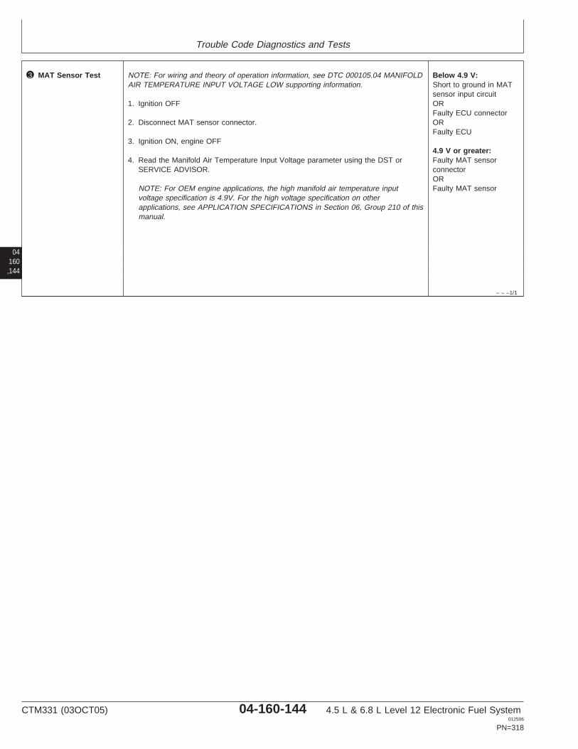
Trouble Code Diagnostics and Tests
04160,144
– – –1/1
3 MAT Sensor Test NOTE: For wiring and theory of operation information, see DTC 000105.04 MANIFOLDAIR TEMPERATURE INPUT VOLTAGE LOW supporting information.
1. Ignition OFF
2. Disconnect MAT sensor connector.
3. Ignition ON, engine OFF
4. Read the Manifold Air Temperature Input Voltage parameter using the DST orSERVICE ADVISOR.
NOTE: For OEM engine applications, the high manifold air temperature inputvoltage specification is 4.9V. For the high voltage specification on otherapplications, see APPLICATION SPECIFICATIONS in Section 06, Group 210 of thismanual.
Below 4.9 V:Short to ground in MATsensor input circuitORFaulty ECU connectorORFaulty ECU
4.9 V or greater:Faulty MAT sensorconnectorORFaulty MAT sensor
CTM331 (03OCT05) 04-160-144 4.5 L & 6.8 L Level 12 Electronic Fuel System012506
PN=318

Trouble Code Diagnostics and Tests
04160,145
CTM331 (03OCT05) 04-160-145 4.5 L & 6.8 L Level 12 Electronic Fuel System012506
PN=319
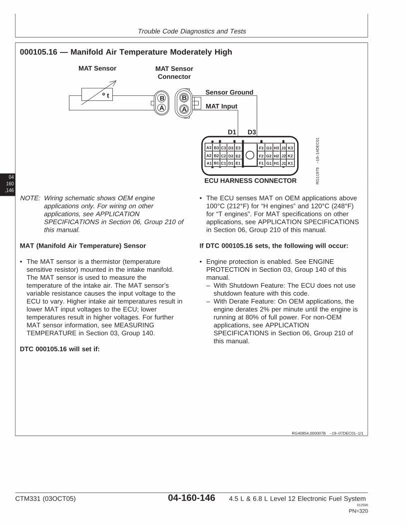
Trouble Code Diagnostics and Tests
04160,146
RG40854,000007B –19–07DEC01–1/1
000105.16 — Manifold Air Temperature Moderately High
D1
A A
BB
D3
MAT SensorConnector
Sensor Ground
MAT Input
MAT Sensor
t
A1
A2
A3 B3 C3 D3 E3
B2 C2 D2 E2
B1 C1 D1 E1 F1
F2
F3 G3 H3 J3 K3
G2 H2 J2 K2
G1 H1 J1 K1
ECU HARNESS CONNECTOR RG
1197
9–1
9–14
DE
C01
NOTE: Wiring schematic shows OEM engineapplications only. For wiring on otherapplications, see APPLICATIONSPECIFICATIONS in Section 06, Group 210 ofthis manual.
MAT (Manifold Air Temperature) Sensor
• The MAT sensor is a thermistor (temperaturesensitive resistor) mounted in the intake manifold.The MAT sensor is used to measure thetemperature of the intake air. The MAT sensor’svariable resistance causes the input voltage to theECU to vary. Higher intake air temperatures result inlower MAT input voltages to the ECU; lowertemperatures result in higher voltages. For furtherMAT sensor information, see MEASURINGTEMPERATURE in Section 03, Group 140.
DTC 000105.16 will set if:
• The ECU senses MAT on OEM applications above100°C (212°F) for “H engines” and 120°C (248°F)for “T engines”. For MAT specifications on otherapplications, see APPLICATION SPECIFICATIONSin Section 06, Group 210 of this manual.
If DTC 000105.16 sets, the following will occur:
• Engine protection is enabled. See ENGINEPROTECTION in Section 03, Group 140 of thismanual.– With Shutdown Feature: The ECU does not use
shutdown feature with this code.– With Derate Feature: On OEM applications, the
engine derates 2% per minute until the engine isrunning at 80% of full power. For non-OEMapplications, see APPLICATIONSPECIFICATIONS in Section 06, Group 210 ofthis manual.
CTM331 (03OCT05) 04-160-146 4.5 L & 6.8 L Level 12 Electronic Fuel System012506
PN=320
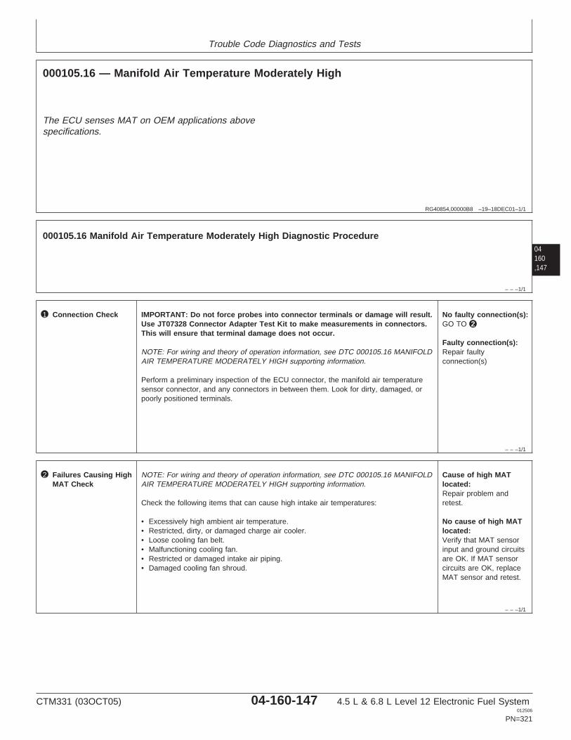
Trouble Code Diagnostics and Tests
RG40854,00000B8 –19–18DEC01–1/1
000105.16 — Manifold Air Temperature Moderately High
The ECU senses MAT on OEM applications abovespecifications.
04160,147
– – –1/1
000105.16 Manifold Air Temperature Moderately High Diagnostic Procedure
– – –1/1
1 Connection Check IMPORTANT: Do not force probes into connector terminals or damage will result.Use JT07328 Connector Adapter Test Kit to make measurements in connectors.This will ensure that terminal damage does not occur.
NOTE: For wiring and theory of operation information, see DTC 000105.16 MANIFOLDAIR TEMPERATURE MODERATELY HIGH supporting information.
Perform a preliminary inspection of the ECU connector, the manifold air temperaturesensor connector, and any connectors in between them. Look for dirty, damaged, orpoorly positioned terminals.
No faulty connection(s):GO TO 2
Faulty connection(s):Repair faultyconnection(s)
– – –1/1
2 Failures Causing HighMAT Check
NOTE: For wiring and theory of operation information, see DTC 000105.16 MANIFOLDAIR TEMPERATURE MODERATELY HIGH supporting information.
Check the following items that can cause high intake air temperatures:
• Excessively high ambient air temperature.• Restricted, dirty, or damaged charge air cooler.• Loose cooling fan belt.• Malfunctioning cooling fan.• Restricted or damaged intake air piping.• Damaged cooling fan shroud.
Cause of high MATlocated:Repair problem andretest.
No cause of high MATlocated:Verify that MAT sensorinput and ground circuitsare OK. If MAT sensorcircuits are OK, replaceMAT sensor and retest.
CTM331 (03OCT05) 04-160-147 4.5 L & 6.8 L Level 12 Electronic Fuel System012506
PN=321
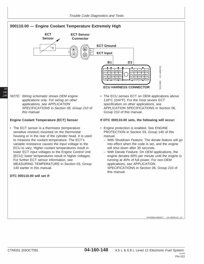
Trouble Code Diagnostics and Tests
04160,148
RG40854,0000071 –19–06DEC01–1/1
000110.00 — Engine Coolant Temperature Extremely High
t
ECT SensorConnector
ECT Ground
ECT Input
ECTSensor
B1 D3
B
A
B
A
A1
A2
A3 B3 C3 D3 E3
B2 C2 D2 E2
B1 C1 D1 E1 F1
F2
F3 G3 H3 J3 K3
G2 H2 J2 K2
G1 H1 J1 K1
ECU HARNESS CONNECTOR RG
1198
0–1
9–14
DE
C01
NOTE: Wiring schematic shows OEM engineapplications only. For wiring on otherapplications, see APPLICATIONSPECIFICATIONS in Section 06, Group 210 ofthis manual.
Engine Coolant Temperature (ECT) Sensor
• The ECT sensor is a thermistor (temperaturesensitive resistor) mounted on the thermostathousing or in the rear of the cylinder head. It is usedto measure the coolant temperature. The ECT’svariable resistance causes the input voltage to theECU to vary. Higher coolant temperatures result inlower ECT input voltages to the Engine Control Unit(ECU); lower temperatures result in higher voltages.For further ECT sensor information, seeMEASURING TEMPERATURE in Section 03, Group140 earlier in this manual.
DTC 000110.00 will set if:
• The ECU senses ECT on OEM applications above118°C (244°F). For the most severe ECTspecification on other applications, seeAPPLICATION SPECIFICATIONS in Section 06,Group 210 of this manual.
If DTC 000110.00 sets, the following will occur:
• Engine protection is enabled. See ENGINEPROTECTION in Section 03, Group 140 of thismanual.– With Shutdown Feature: The derate feature will go
into effect when the code is set, and the enginewill shut down after 30 seconds.
– With Derate Feature: On OEM applications, theengine derates 60% per minute until the engine isrunning at 40% of full power. For non-OEMapplications, see APPLICATIONSPECIFICATIONS in Section 06, Group 210 ofthis manual.
CTM331 (03OCT05) 04-160-148 4.5 L & 6.8 L Level 12 Electronic Fuel System012506
PN=322
Trouble Code Diagnostics and Tests
RG40854,00000B9 –19–18DEC01–1/1
000110.00 — Engine Coolant Temperature Extremely High
The ECU senses ECT above specification.
04160,149
– – –1/1
000110.00 Engine Coolant Temperature Extremely High Diagnostic Procedure
– – –1/1
1 Connection Check IMPORTANT: Do not force probes into connector terminals or damage will result.Use JT07328 Connector Adapter Test Kit to make measurements in connectors.This will ensure that terminal damage does not occur.
NOTE: For wiring and theory of operation information, see DTC 000110.00 ENGINECOOLANT TEMPERATURE EXTREMELY HIGH supporting information
Perform a preliminary inspection of the ECU connector, the Engine CoolantTemperature (ECT) connector, and any connectors in between them. Look for dirty,damaged, or poorly positioned terminals.
No faulty connection(s):GO TO 2
Faulty connection(s):Repair faultyconnection(s)
– – –1/1
2 ECT Sensor andCircuit Test
NOTE: For wiring and theory of operation information, see DTC 000110.00 ENGINECOOLANT TEMPERATURE EXTREMELY HIGH supporting information
Under the conditions where DTC 000110.00 occurs, use a temperature gauge andverify that engine coolant temperature is above the most severe ECT specification.
NOTE: cations, the most severe ECT specification is 118°C (244°F). For the mostsevere ECT specification on other applications, see APPLICATION SPECIFICATIONSin Section 06, Group 210 of this manual.
ECT 118°C (244°F) orabove:Engine overheatingproblem. See 4.5L/6.8L -C1 - ENGINE COOLANTTEMPERATURE ABOVENORMAL in Section 04,Group 150 of 4.5 L & 6.8L Diesel Engines BaseEngine Manual (CTM104).
ECT significantly lessthan 118°C (244°F):Verify that ECT input andground circuits are OKIf both circuits are OK,replace ECT sensor andretest
CTM331 (03OCT05) 04-160-149 4.5 L & 6.8 L Level 12 Electronic Fuel System012506
PN=323
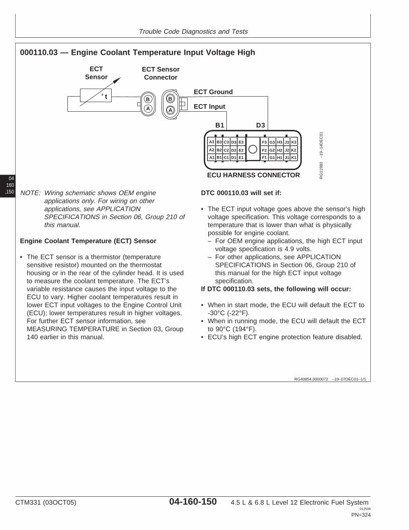
Trouble Code Diagnostics and Tests
04160,150
RG40854,0000072 –19–07DEC01–1/1
000110.03 — Engine Coolant Temperature Input Voltage High
t
ECT SensorConnector
ECT Ground
ECT Input
ECTSensor
B1 D3
B
A
B
A
A1
A2
A3 B3 C3 D3 E3
B2 C2 D2 E2
B1 C1 D1 E1 F1
F2
F3 G3 H3 J3 K3
G2 H2 J2 K2
G1 H1 J1 K1
ECU HARNESS CONNECTOR RG
1198
0–1
9–14
DE
C01
NOTE: Wiring schematic shows OEM engineapplications only. For wiring on otherapplications, see APPLICATIONSPECIFICATIONS in Section 06, Group 210 ofthis manual.
Engine Coolant Temperature (ECT) Sensor
• The ECT sensor is a thermistor (temperaturesensitive resistor) mounted on the thermostathousing or in the rear of the cylinder head. It is usedto measure the coolant temperature. The ECT’svariable resistance causes the input voltage to theECU to vary. Higher coolant temperatures result inlower ECT input voltages to the Engine Control Unit(ECU); lower temperatures result in higher voltages.For further ECT sensor information, seeMEASURING TEMPERATURE in Section 03, Group140 earlier in this manual.
DTC 000110.03 will set if:
• The ECT input voltage goes above the sensor’s highvoltage specification. This voltage corresponds to atemperature that is lower than what is physicallypossible for engine coolant.– For OEM engine applications, the high ECT input
voltage specification is 4.9 volts.– For other applications, see APPLICATION
SPECIFICATIONS in Section 06, Group 210 ofthis manual for the high ECT input voltagespecification.
If DTC 000110.03 sets, the following will occur:
• When in start mode, the ECU will default the ECT to-30°C (-22°F).
• When in running mode, the ECU will default the ECTto 90°C (194°F).
• ECU’s high ECT engine protection feature disabled.
CTM331 (03OCT05) 04-160-150 4.5 L & 6.8 L Level 12 Electronic Fuel System012506
PN=324
Trouble Code Diagnostics and Tests
RG40854,00000BA –19–23SEP05–1/1
000110.03 — Engine Coolant Temperature Input Voltage High
The ECT input voltage goes above the sensor’s highvoltage specification.
04160,151
– – –1/1
000110.03 Engine Coolant Temperature Input Voltage High Diagnostic Procedure
– – –1/1
1 Connection Check IMPORTANT: Do not force probes into connector terminals or damage will result.Use JT07328 Connector Adapter Test Kit to make measurements in connectors.This will ensure that terminal damage does not occur.
NOTE: For wiring and theory of operation information, see DTC 000110.03 ENGINECOOLANT TEMPERATURE INPUT VOLTAGE HIGH supporting information
Perform a preliminary inspection of the ECU connector, the Engine CoolantTemperature (ECT) connector, and any connectors in between them. Look for dirty,damaged, or poorly positioned terminals.
No faulty connection(s):GO TO 2
Faulty connection(s):Repair faultyconnection(s)
– – –1/1
2 Intermittent Fault Test NOTE: For wiring and theory of operation information, see DTC 000110.03 ENGINECOOLANT TEMPERATURE INPUT VOLTAGE HIGH supporting information
1. Connect to the DST or SERVICE ADVISOR.
2. Ignition ON, engine OFF
3. Start the ECU communication software
4. Ignition ON, engine running
5. Read the Engine Coolant Temperature Input Voltage parameter using SERVICEADVISOR.
NOTE: On OEM applications, the high ECT input voltage specification is 4.9V. Forhigh input voltage specifications on other applications, see APPLICATIONSPECIFICATIONS in Section 06, Group 210 of this manual.
At or above 4.9 V:GO TO 3
Below 4.9 V:Problem is intermittent. Ifno other codes arepresent, seeINTERMITTENT FAULTDIAGNOSTICS, earlier inthis Group.
SERVICE ADVISOR is a trademark of Deere & Company
CTM331 (03OCT05) 04-160-151 4.5 L & 6.8 L Level 12 Electronic Fuel System012506
PN=325
Trouble Code Diagnostics and Tests
04160,152
– – –1/1
3 Engine CoolantTemperature (ECT)Sensor andConnector Test
NOTE: For wiring and theory of operation information, see DTC 000110.03 ENGINECOOLANT TEMPERATURE INPUT VOLTAGE HIGH supporting information
1. Ignition OFF
2. Disconnect ECT sensor connector
3. Install a jumper wire between both terminals in the ECT sensor harness connector
4. Ignition ON, engine OFF
5. Read the Engine Coolant Temperature Input Voltage parameter using the DST orSERVICE ADVISOR.
NOTE: On OEM applications, the low ECT input voltage specification is 0.1 voltsand below. For ECT input voltage specifications on other applications, seeAPPLICATION SPECIFICATIONS in Section 06, Group 210 of this manual.
Above 0.1 V:GO TO 4
At or below 0.1 V:Faulty ECT sensorconnectorORFaulty ECT sensor
– – –1/1
4 Engine CoolantTemperature (ECT)Open Ground Test
NOTE: For wiring and theory of operation information, see DTC 000110.03 ENGINECOOLANT TEMPERATURE INPUT VOLTAGE HIGH supporting information
1. Ignition OFF
2. Remove jumper wire between both terminals
3. Install jumper wire between ECT sensor harness connector input terminal and agood chassis ground
4. Ignition ON, engine OFF
5. Read the Engine Coolant Temperature Input Voltage parameter using the DST orSERVICE ADVISOR.
NOTE: On OEM applications, the low ECT input voltage specification is 0.1 voltsand below. For ECT input voltage specifications on other applications, seeAPPLICATION SPECIFICATIONS in Section 06, Group 210 of this manual.
Above 0.1 V:Open in ECT inputsensor circuitORFaulty ECU connectionORFaulty ECU
0.1 V or below:Open in ECT sensorground circuitORFaulty ECU connectionORFaulty ECU
CTM331 (03OCT05) 04-160-152 4.5 L & 6.8 L Level 12 Electronic Fuel System012506
PN=326

Trouble Code Diagnostics and Tests
04160,153
CTM331 (03OCT05) 04-160-153 4.5 L & 6.8 L Level 12 Electronic Fuel System012506
PN=327
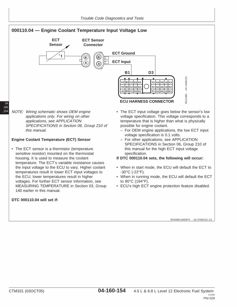
Trouble Code Diagnostics and Tests
04160,154
RG40854,0000074 –19–07DEC01–1/1
000110.04 — Engine Coolant Temperature Input Voltage Low
t
ECT SensorConnector
ECT Ground
ECT Input
ECTSensor
B1 D3
B
A
B
A
A1
A2
A3 B3 C3 D3 E3
B2 C2 D2 E2
B1 C1 D1 E1 F1
F2
F3 G3 H3 J3 K3
G2 H2 J2 K2
G1 H1 J1 K1
ECU HARNESS CONNECTOR RG
1198
0–1
9–14
DE
C01
NOTE: Wiring schematic shows OEM engineapplications only. For wiring on otherapplications, see APPLICATIONSPECIFICATIONS in Section 06, Group 210 ofthis manual.
Engine Coolant Temperature (ECT) Sensor
• The ECT sensor is a thermistor (temperaturesensitive resistor) mounted on the thermostathousing. It is used to measure the coolanttemperature. The ECT’s variable resistance causesthe input voltage to the ECU to vary. Higher coolanttemperatures result in lower ECT input voltages tothe ECU; lower temperatures result in highervoltages. For further ECT sensor information, seeMEASURING TEMPERATURE in Section 03, Group140 earlier in this manual.
DTC 000110.04 will set if:
• The ECT input voltage goes below the sensor’s lowvoltage specification. This voltage corresponds to atemperature that is higher than what is physicallypossible for engine coolant.– For OEM engine applications, the low ECT input
voltage specification is 0.1 volts.– For other applications, see APPLICATION
SPECIFICATIONS in Section 06, Group 210 ofthis manual for the high ECT input voltagespecification.
If DTC 000110.04 sets, the following will occur:
• When in start mode, the ECU will default the ECT to-30°C (-22°F).
• When in running mode, the ECU will default the ECTto 90°C (194°F).
• ECU’s high ECT engine protection feature disabled.
CTM331 (03OCT05) 04-160-154 4.5 L & 6.8 L Level 12 Electronic Fuel System012506
PN=328

Trouble Code Diagnostics and Tests
RG40854,00000BB –19–23SEP05–1/1
000110.04 — Engine Coolant Temperature Input Voltage Low
The ECT input voltage goes below the sensor’s lowvoltage specification.
04160,155
– – –1/1
000110.04 Engine Coolant Temperature Input Voltage Low Diagnostic Procedure
– – –1/1
1 Connection Check IMPORTANT: Do not force probes into connector terminals or damage will result.Use JT07328 Connector Adapter Test Kit to make measurements in connectors.This will ensure that terminal damage does not occur.
NOTE: For wiring and theory of operation information, see DTC 000110.04 ENGINECOOLANT TEMPERATURE INPUT VOLTAGE LOW supporting information
Perform a preliminary inspection of the ECU connector, the Engine CoolantTemperature (ECT) sensor connector, and any connectors in between them. Look fordirty, damaged, or poorly positioned terminals.
No faulty connection(s):GO TO 2
Faulty connection(s):Repair faultyconnection(s)
– – –1/1
2 Intermittent Fault Test NOTE: For wiring and theory of operation information, see DTC 000110.04 ENGINECOOLANT TEMPERATURE INPUT VOLTAGE LOW supporting information
1. Connect to the DST orSERVICE ADVISOR.
2. Ignition ON, engine OFF
3. Start the ECU communication software
4. Ignition ON, engine OFF
5. Read the Engine Coolant Temperature Input Voltage parameter using SERVICEADVISOR.
NOTE: For OEM engine applications, the low ECT input voltage specification is0.1V. For the low voltage specification on other applications, see APPLICATIONSPECIFICATIONS in Section 06, Group 210 of this manual.
0.1 V or below:GO TO 3
Above 0.1 V:Problem is intermittent. Ifno other codes arepresent, seeINTERMITTENT FAULTDIAGNOSTICS, earlier inthis Group.
SERVICE ADVISOR is a trademark of Deere & Company
CTM331 (03OCT05) 04-160-155 4.5 L & 6.8 L Level 12 Electronic Fuel System012506
PN=329
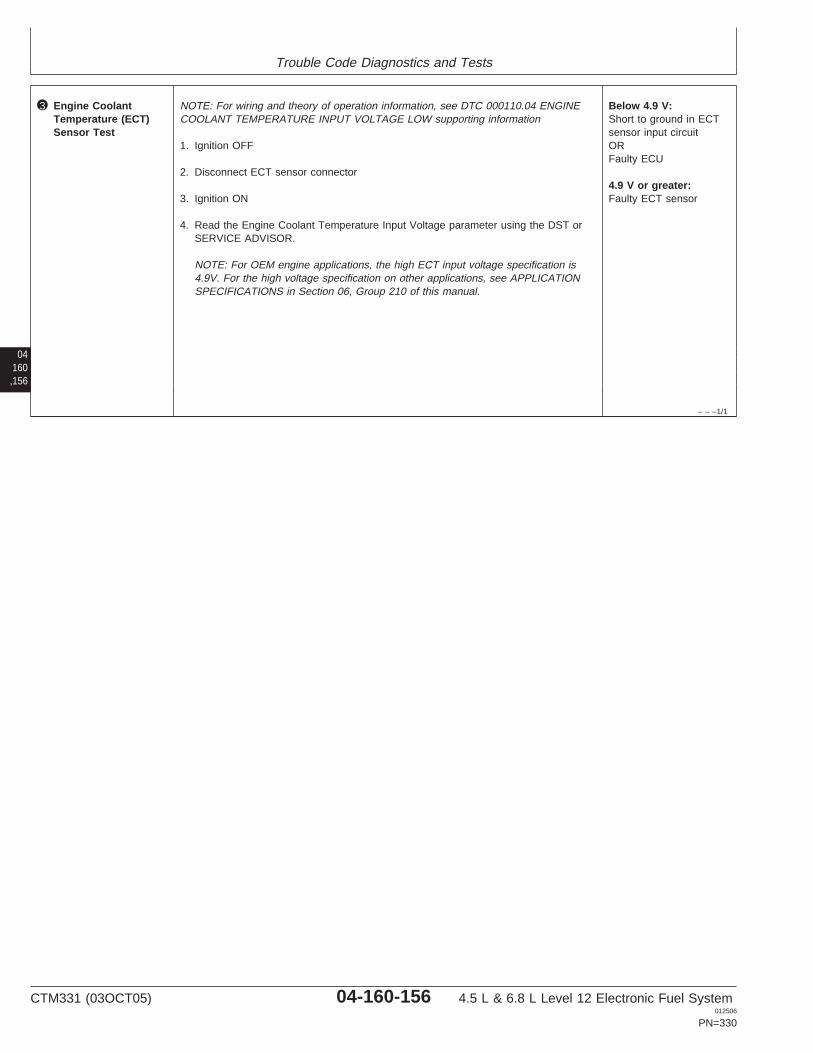
Trouble Code Diagnostics and Tests
04160,156
– – –1/1
3 Engine CoolantTemperature (ECT)Sensor Test
NOTE: For wiring and theory of operation information, see DTC 000110.04 ENGINECOOLANT TEMPERATURE INPUT VOLTAGE LOW supporting information
1. Ignition OFF
2. Disconnect ECT sensor connector
3. Ignition ON
4. Read the Engine Coolant Temperature Input Voltage parameter using the DST orSERVICE ADVISOR.
NOTE: For OEM engine applications, the high ECT input voltage specification is4.9V. For the high voltage specification on other applications, see APPLICATIONSPECIFICATIONS in Section 06, Group 210 of this manual.
Below 4.9 V:Short to ground in ECTsensor input circuitORFaulty ECU
4.9 V or greater:Faulty ECT sensor
CTM331 (03OCT05) 04-160-156 4.5 L & 6.8 L Level 12 Electronic Fuel System012506
PN=330

Trouble Code Diagnostics and Tests
04160,157
CTM331 (03OCT05) 04-160-157 4.5 L & 6.8 L Level 12 Electronic Fuel System012506
PN=331

Trouble Code Diagnostics and Tests
04160,158
RG40854,0000076 –19–07DEC01–1/1
000110.15 — Engine Coolant Temperature High Least Severe
t
ECT SensorConnector
ECT Ground
ECT Input
ECTSensor
B1 D3
B
A
B
A
A1
A2
A3 B3 C3 D3 E3
B2 C2 D2 E2
B1 C1 D1 E1 F1
F2
F3 G3 H3 J3 K3
G2 H2 J2 K2
G1 H1 J1 K1
ECU HARNESS CONNECTOR RG
1198
0–1
9–14
DE
C01
NOTE: Wiring schematic shows OEM engineapplications only. For wiring on otherapplications, see APPLICATIONSPECIFICATIONS in Section 06, Group 210 ofthis manual.
Engine Coolant Temperature (ECT) Sensor
• The ECT sensor is a thermistor (temperaturesensitive resistor) mounted on the thermostathousing or at the rear of the cylinder head. It is usedto measure the coolant temperature. The ECT’svariable resistance causes the input voltage to theECU to vary. Higher coolant temperatures result inlower ECT input voltages to the ECU; lowertemperatures result in higher voltages. For furtherECT sensor information, see MEASURINGTEMPERATURE in Section 03, Group 140 earlier inthis manual.
DTC 000110.15 will set if:
• The ECU senses ECT on OEM applications above108°C (226°F). For the least severe ECTspecification on other applications, seeAPPLICATION SPECIFICATIONS in Section 06,Group 210 of this manual.
If DTC 000110.15 sets, the following will occur:
• Engine protection is enabled. See ENGINEPROTECTION in Section 03, Group 140 of thismanual.– With Shutdown Feature: No shutdown available
for this code.– With Derate Feature: On OEM applications, the
engine derates 2% per minute until the engine isrunning at 95% of full power. For non-OEMapplications, see APPLICATIONSPECIFICATIONS in Section 06, Group 210 ofthis manual.
CTM331 (03OCT05) 04-160-158 4.5 L & 6.8 L Level 12 Electronic Fuel System012506
PN=332
Trouble Code Diagnostics and Tests
RG40854,00000BC –19–07SEP05–1/1
000110.15 — Engine Coolant Temperature High Least Severe
The ECU senses ECT above specification.
04160,159
– – –1/1
000110.15 Engine Coolant Temperature High Least Severe Diagnostic Procedure
– – –1/1
1 Connection Check IMPORTANT: Do not force probes into connector terminals or damage will result.Use JT07328 Connector Adapter Test Kit to make measurements in connectors.This will ensure that terminal damage does not occur.
NOTE: For wiring and theory of operation information, see DTC 000110.15 ENGINECOOLANT TEMPERATURE HIGH LEAST SEVERE supporting information
Perform a preliminary inspection of the ECU connector, the Engine CoolantTemperature (ECT) sensor connector, and any connectors in between them. Look fordirty, damaged, or poorly positioned terminals.
No faulty connection(s):GO TO 2
Faulty connection(s):Repair faultyconnection(s)
– – –1/1
2 Engine CoolantTemperature (ECT)Sensor and CircuitTest
NOTE: For wiring and theory of operation information, see DTC 000110.15 ENGINECOOLANT TEMPERATURE HIGH LEAST SEVERE supporting information
Under the conditions where DTC 000110.15 occurs, using a temperature gauge, verifythat engine coolant temperature is above the least severe ECT specification.
NOTE: On OEM applications, the least severe ECT specification is 108°C (226°F). Forthe least severe ECT specification on other applications, see APPLICATIONSPECIFICATIONS in Section 06, Group 210 of this manual.
ECT above 108°C(226°F):
Engine overheatingproblem. See 4.5L/6.8L -C1 - ENGINE COOLANTTEMPERATURE ABOVENORMAL in Section 04,Group 150 of 4.5 L & 6.8L Diesel Engines BaseEngine Manual (CTM104).
ECT significantly lessthan 108°C (226°F):Verify that ECT sensorinput and ground circuitsare OK.If ECT sensor circuits areOK, replace ECT sensorand retest
CTM331 (03OCT05) 04-160-159 4.5 L & 6.8 L Level 12 Electronic Fuel System012506
PN=333
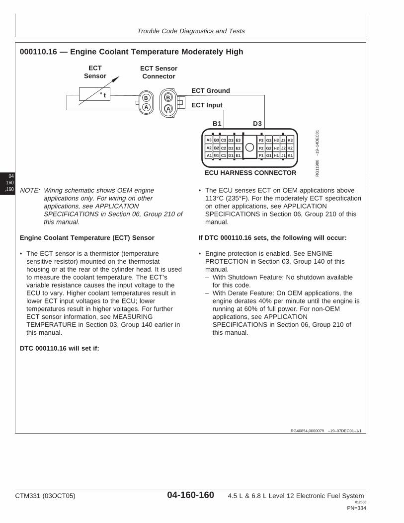
Trouble Code Diagnostics and Tests
04160,160
RG40854,0000079 –19–07DEC01–1/1
000110.16 — Engine Coolant Temperature Moderately High
t
ECT SensorConnector
ECT Ground
ECT Input
ECTSensor
B1 D3
B
A
B
A
A1
A2
A3 B3 C3 D3 E3
B2 C2 D2 E2
B1 C1 D1 E1 F1
F2
F3 G3 H3 J3 K3
G2 H2 J2 K2
G1 H1 J1 K1
ECU HARNESS CONNECTOR RG
1198
0–1
9–14
DE
C01
NOTE: Wiring schematic shows OEM engineapplications only. For wiring on otherapplications, see APPLICATIONSPECIFICATIONS in Section 06, Group 210 ofthis manual.
Engine Coolant Temperature (ECT) Sensor
• The ECT sensor is a thermistor (temperaturesensitive resistor) mounted on the thermostathousing or at the rear of the cylinder head. It is usedto measure the coolant temperature. The ECT’svariable resistance causes the input voltage to theECU to vary. Higher coolant temperatures result inlower ECT input voltages to the ECU; lowertemperatures result in higher voltages. For furtherECT sensor information, see MEASURINGTEMPERATURE in Section 03, Group 140 earlier inthis manual.
DTC 000110.16 will set if:
• The ECU senses ECT on OEM applications above113°C (235°F). For the moderately ECT specificationon other applications, see APPLICATIONSPECIFICATIONS in Section 06, Group 210 of thismanual.
If DTC 000110.16 sets, the following will occur:
• Engine protection is enabled. See ENGINEPROTECTION in Section 03, Group 140 of thismanual.– With Shutdown Feature: No shutdown available
for this code.– With Derate Feature: On OEM applications, the
engine derates 40% per minute until the engine isrunning at 60% of full power. For non-OEMapplications, see APPLICATIONSPECIFICATIONS in Section 06, Group 210 ofthis manual.
CTM331 (03OCT05) 04-160-160 4.5 L & 6.8 L Level 12 Electronic Fuel System012506
PN=334
Trouble Code Diagnostics and Tests
RG40854,00000BD –19–07SEP05–1/1
000110.16 — Engine Coolant Temperature Moderately High
The ECU senses ECT above specification.
04160,161
– – –1/1
000110.16 Engine Coolant Temperature Moderately High Diagnostic Procedure
– – –1/1
1 Connection Check IMPORTANT: Do not force probes into connector terminals or damage will result.Use JT07328 Connector Adapter Test Kit to make measurements in connectors.This will ensure that terminal damage does not occur.
NOTE: For wiring and theory of operation information, see DTC 000110.16 ENGINECOOLANT TEMPERATURE MODERATELY HIGH supporting information
Perform a preliminary inspection of the ECU connector, the Engine CoolantTemperature (ECT) sensor connector, and any connectors in between them. Look fordirty, damaged, or poorly positioned terminals.
No faulty connection(s):GO TO 2
Faulty connection(s):Repair faultyconnection(s)
– – –1/1
2 Engine CoolantTemperature (ECT)Sensor and CircuitTest
NOTE: For wiring and theory of operation information, see DTC 000110.16 ENGINECOOLANT TEMPERATURE MODERATELY HIGH supporting information
Under the conditions where DTC 000110.16 occurs, using a temperature gauge, verifythat engine coolant temperature is above 113°C (235°F).
NOTE: On OEM applications, the moderately high ECT specification is 113°C (235°F).For the moderately high ECT specification on other applications, see APPLICATIONSPECIFICATIONS in Section 06, Group 210 of this manual.
ECT above 113°C(235°F):
Engine overheatingproblem. See 4.5L/6.8L -C1 - ENGINE COOLANTTEMPERATURE ABOVENORMAL in Section 04,Group 150 of 4.5 L & 6.8L Diesel Engines BaseEngine Manual (CTM104).
ECT significantly lessthan 113°C (235°F):Verify that ECT sensorinput and ground circuitsare OK.If ECT sensor circuits areOK, replace ECT sensorand retest
CTM331 (03OCT05) 04-160-161 4.5 L & 6.8 L Level 12 Electronic Fuel System012506
PN=335
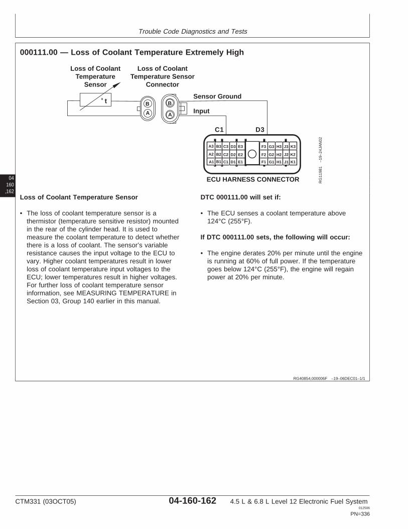
Trouble Code Diagnostics and Tests
04160,162
RG40854,000006F –19–06DEC01–1/1
000111.00 — Loss of Coolant Temperature Extremely High
tSensor Ground
Input
C1 D3
B
A
B
A
A1
A2
A3 B3 C3 D3 E3
B2 C2 D2 E2
B1 C1 D1 E1 F1
F2
F3 G3 H3 J3 K3
G2 H2 J2 K2
G1 H1 J1 K1
ECU HARNESS CONNECTOR
Loss of CoolantTemperature Sensor
Connector
Loss of CoolantTemperature
Sensor
RG
1198
1–1
9–24
JAN
02
Loss of Coolant Temperature Sensor
• The loss of coolant temperature sensor is athermistor (temperature sensitive resistor) mountedin the rear of the cylinder head. It is used tomeasure the coolant temperature to detect whetherthere is a loss of coolant. The sensor’s variableresistance causes the input voltage to the ECU tovary. Higher coolant temperatures result in lowerloss of coolant temperature input voltages to theECU; lower temperatures result in higher voltages.For further loss of coolant temperature sensorinformation, see MEASURING TEMPERATURE inSection 03, Group 140 earlier in this manual.
DTC 000111.00 will set if:
• The ECU senses a coolant temperature above124°C (255°F).
If DTC 000111.00 sets, the following will occur:
• The engine derates 20% per minute until the engineis running at 60% of full power. If the temperaturegoes below 124°C (255°F), the engine will regainpower at 20% per minute.
CTM331 (03OCT05) 04-160-162 4.5 L & 6.8 L Level 12 Electronic Fuel System012506
PN=336
Trouble Code Diagnostics and Tests
RG40854,00000BE –19–07SEP05–1/1
000111.00 — Loss of Coolant Temperature Extremely High
The ECU senses a coolant temperature abovespecification.
04160,163
– – –1/1
000111.00 Loss of Coolant Temperature Extremely High Diagnostic Procedure
– – –1/1
1 Connection Check IMPORTANT: Do not force probes into connector terminals or damage will result.Use JT07328 Connector Adapter Test Kit to make measurements in connectors.This will ensure that terminal damage does not occur.
NOTE: For wiring and theory of operation information, see DTC 000111.00 LOSS OFCOOLANT TEMPERATURE EXTREMELY HIGH supporting information
Perform a preliminary inspection of the ECU connector, the loss of coolant temperaturesensor connector, and any connectors in between them. Look for dirty, damaged, orpoorly positioned terminals.
No faulty connection(s):GO TO 2
Faulty connection(s):Repair faultyconnection(s)
CTM331 (03OCT05) 04-160-163 4.5 L & 6.8 L Level 12 Electronic Fuel System012506
PN=337
Trouble Code Diagnostics and Tests
04160,164
– – –1/1
2 Loss of CoolantTemperature Sensorand Circuit Test
NOTE: For wiring and theory of operation information, see DTC 000111.00 LOSS OFCOOLANT TEMPERATURE EXTREMELY HIGH supporting information
Under the conditions where DTC 000111.00 occurs, using a temperature gauge, verifythat loss of coolant temperature is above 124°C (255°F).
Significantly less than124°C (255°F):Verify that loss of coolanttemperature sensor inputand ground circuits areOK.If loss of coolanttemperature sensorcircuits are OK, replaceloss of coolanttemperature sensor andretest
Temperature above124°C (255°F):Engine overheatingproblem. See 4.5L/6.8L -C1 - ENGINE COOLANTTEMPERATURE ABOVENORMAL in Section 04,Group 150 of 4.5 L & 6.8L Diesel Engines BaseEngine Manual (CTM104).
CTM331 (03OCT05) 04-160-164 4.5 L & 6.8 L Level 12 Electronic Fuel System012506
PN=338

Trouble Code Diagnostics and Tests
04160,165
CTM331 (03OCT05) 04-160-165 4.5 L & 6.8 L Level 12 Electronic Fuel System012506
PN=339

Trouble Code Diagnostics and Tests
04160,166
RG40854,00000C0 –19–19DEC01–1/1
000111.03 — Loss of Coolant Temperature Input Voltage High
tSensor Ground
Input
C1 D3
B
A
B
A
A1
A2
A3 B3 C3 D3 E3
B2 C2 D2 E2
B1 C1 D1 E1 F1
F2
F3 G3 H3 J3 K3
G2 H2 J2 K2
G1 H1 J1 K1
ECU HARNESS CONNECTOR
Loss of CoolantTemperature Sensor
Connector
Loss of CoolantTemperature
Sensor
RG
1198
1–1
9–24
JAN
02
Loss of Coolant Temperature Sensor
• The loss of coolant temperature sensor is athermistor (temperature sensitive resistor) mountedin the rear of the cylinder head. It is used tomeasure the coolant temperature to detect whetherthere is a loss of coolant. The sensor’s variableresistance causes the input voltage to the ECU tovary. Higher coolant temperatures result in lowerloss of coolant temperature input voltages to theECU; lower temperatures result in higher voltages.For further loss of coolant temperature sensorinformation, see MEASURING TEMPERATURE inSection 03, Group 140 earlier in this manual.
DTC 000111.03 will set if:
• The loss of coolant temperature input voltageexceeds 4.9 volts. This voltage corresponds to atemperature that is lower than what is physicallypossible for engine coolant.
If DTC 000111.03 sets, the following will occur:
• ECU’s high loss of coolant temperature engineprotection feature disabled.
CTM331 (03OCT05) 04-160-166 4.5 L & 6.8 L Level 12 Electronic Fuel System012506
PN=340
Trouble Code Diagnostics and Tests
RG40854,00000C1 –19–23SEP05–1/1
000111.03 — Loss of Coolant Temperature Input Voltage High
The loss of coolant temperature input voltage exceeds4.9 volts. This voltage corresponds to a temperature
that is lower than what is physically possible for enginecoolant.
04160,167
– – –1/1
000111.03 Loss of Coolant Temperature Input Voltage High Diagnostic Procedure
– – –1/1
1 Connection Check IMPORTANT: Do not force probes into connector terminals or damage will result.Use JT07328 Connector Adapter Test Kit to make measurements in connectors.This will ensure that terminal damage does not occur.
NOTE: For wiring and theory of operation information, see DTC 000111.03 LOSS OFCOOLANT TEMPERATURE INPUT VOLTAGE HIGH supporting information
Perform a preliminary inspection of the ECU connector, the loss of coolant temperaturesensor connector, and any connectors in between them. Look for dirty, damaged, orpoorly positioned terminals.
No faulty connection(s):GO TO 2
Faulty connection(s):Repair faultyconnection(s)
– – –1/1
2 Intermittent Fault Test NOTE: For wiring and theory of operation information, see DTC 000111.03 LOSS OFCOOLANT TEMPERATURE INPUT VOLTAGE HIGH supporting information
1. Connect to the DST or SERVICE ADVISOR.
2. Ignition ON, engine OFF
3. Start the ECU communication software
4. Read DTCs using the DST orSERVICE ADVISOR.
5. Make note of any DTCs, then clear all DTCs
6. Ignition ON, engine running
7. Read DTCs using the DST orSERVICE ADVISOR.
000111.03 reoccurs:GO TO 3
000111.03 does notreoccur:Problem is intermittent. Ifno other codes arepresent, seeINTERMITTENT FAULTDIAGNOSTICS, earlier inthis Group.
SERVICE ADVISOR is a trademark of Deere & Company
CTM331 (03OCT05) 04-160-167 4.5 L & 6.8 L Level 12 Electronic Fuel System012506
PN=341
Trouble Code Diagnostics and Tests
– – –1/1
3 Loss of CoolantTemperature Sensorand Connector Test
NOTE: For wiring and theory of operation information, see DTC 000111.03 LOSS OFCOOLANT TEMPERATURE INPUT VOLTAGE HIGH supporting information
1. Ignition OFF
2. Disconnect loss of coolant temperature sensor connector
3. Install a jumper wire between both terminals in the loss of coolant temperaturesensor harness connector
4. Ignition ON, engine OFF
5. Read DTCs using the DST or SERVICE ADVISOR.
000111.03 reoccurs:GO TO 4
000111.04 occurs:Faulty loss of coolanttemperature sensorconnectorORFaulty loss of coolanttemperature sensor
04160,168
– – –1/1
4 Loss of CoolantTemperature OpenGround Test
NOTE: For wiring and theory of operation information, see DTC 000111.03 LOSS OFCOOLANT TEMPERATURE INPUT VOLTAGE HIGH supporting information
1. Ignition OFF
2. Remove jumper wire between both terminals
3. Install jumper wire between loss of coolant temperature sensor harness connectorinput terminal and a good chassis ground
4. Ignition ON, engine OFF
5. Using a multimeter, measure voltage between loss of coolant temperature input (5Vsupply) terminal and a good chassis ground.
Between 4.0 V and 6.0V:Open in loss of coolanttemperature input sensorcircuitORFaulty ECU connectionORFaulty ECU
Below 4.0 V:Open in loss of coolanttemperature sensorground circuitORFaulty ECU connectionORFaulty ECU
CTM331 (03OCT05) 04-160-168 4.5 L & 6.8 L Level 12 Electronic Fuel System012506
PN=342

Trouble Code Diagnostics and Tests
04160,169
CTM331 (03OCT05) 04-160-169 4.5 L & 6.8 L Level 12 Electronic Fuel System012506
PN=343
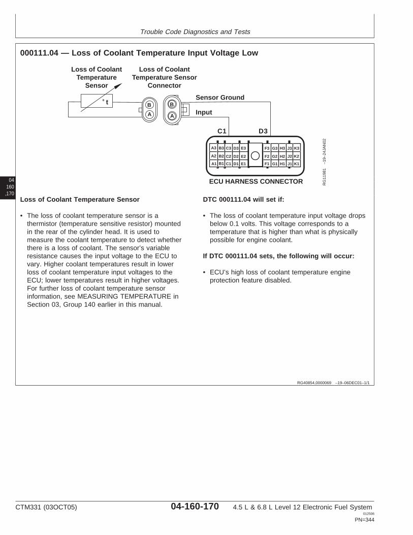
Trouble Code Diagnostics and Tests
04160,170
RG40854,0000069 –19–06DEC01–1/1
000111.04 — Loss of Coolant Temperature Input Voltage Low
tSensor Ground
Input
C1 D3
B
A
B
A
A1
A2
A3 B3 C3 D3 E3
B2 C2 D2 E2
B1 C1 D1 E1 F1
F2
F3 G3 H3 J3 K3
G2 H2 J2 K2
G1 H1 J1 K1
ECU HARNESS CONNECTOR
Loss of CoolantTemperature Sensor
Connector
Loss of CoolantTemperature
Sensor
RG
1198
1–1
9–24
JAN
02
Loss of Coolant Temperature Sensor
• The loss of coolant temperature sensor is athermistor (temperature sensitive resistor) mountedin the rear of the cylinder head. It is used tomeasure the coolant temperature to detect whetherthere is a loss of coolant. The sensor’s variableresistance causes the input voltage to the ECU tovary. Higher coolant temperatures result in lowerloss of coolant temperature input voltages to theECU; lower temperatures result in higher voltages.For further loss of coolant temperature sensorinformation, see MEASURING TEMPERATURE inSection 03, Group 140 earlier in this manual.
DTC 000111.04 will set if:
• The loss of coolant temperature input voltage dropsbelow 0.1 volts. This voltage corresponds to atemperature that is higher than what is physicallypossible for engine coolant.
If DTC 000111.04 sets, the following will occur:
• ECU’s high loss of coolant temperature engineprotection feature disabled.
CTM331 (03OCT05) 04-160-170 4.5 L & 6.8 L Level 12 Electronic Fuel System012506
PN=344

Trouble Code Diagnostics and Tests
RG40854,00000C2 –19–23SEP05–1/1
000111.04 — Loss of Coolant Temperature Input Voltage Low
The loss of coolant temperature input voltage dropsbelow 0.1 volts. This voltage corresponds to a
temperature that is higher than what is physicallypossible for engine coolant.
04160,171
– – –1/1
000111.04 Loss of Coolant Temperature Input Voltage Low Diagnostic Procedure
– – –1/1
1 Connection Check IMPORTANT: Do not force probes into connector terminals or damage will result.Use JT07328 Connector Adapter Test Kit to make measurements in connectors.This will ensure that terminal damage does not occur.
NOTE: For wiring and theory of operation information, see DTC 000111.04 LOSS OFCOOLANT TEMPERATURE INPUT VOLTAGE LOW supporting information
Perform a preliminary inspection of the ECU connector, the loss of coolant temperaturesensor connector, and any connectors in between them. Look for dirty, damaged, orpoorly positioned terminals.
No faulty connection(s):GO TO 2
Faulty connection(s):Repair faultyconnection(s)
– – –1/1
2 Intermittent Fault Test NOTE: For wiring and theory of operation information, see DTC 000111.04 LOSS OFCOOLANT TEMPERATURE INPUT VOLTAGE LOW supporting information
1. Connect to the DST or SERVICE ADVISOR.
2. Ignition ON, engine OFF
3. Start the ECU communication software
4. Read DTCs using the DST orSERVICE ADVISOR.
5. Make note of any DTCs, then clear all DTCs
6. Ignition ON, engine OFF
7. Read DTCs using the DST orSERVICE ADVISOR.
000111.04 reoccurs:GO TO 3
000111.04 does notreoccur:Problem is intermittent. Ifno other codes arepresent, INTERMITTENTFAULT DIAGNOSTICS,earlier in this Group.
SERVICE ADVISOR is a trademark of Deere & Company
CTM331 (03OCT05) 04-160-171 4.5 L & 6.8 L Level 12 Electronic Fuel System012506
PN=345
Trouble Code Diagnostics and Tests
– – –1/1
3 Loss of CoolantTemperature SensorTest
NOTE: For wiring and theory of operation information, DTC 000111.04 LOSS OFCOOLANT TEMPERATURE INPUT VOLTAGE LOW supporting information
1. Ignition OFF
2. Disconnect loss of coolant temperature sensor connector
3. Ignition ON
4. Read DTCs using the DST or SERVICE ADVISOR.
000111.04 reoccurs:Short to ground in loss ofcoolant temperaturesensor input circuitORFaulty ECU
000111.03 occurs:Faulty loss of coolanttemperature sensor
04160,172
CTM331 (03OCT05) 04-160-172 4.5 L & 6.8 L Level 12 Electronic Fuel System012506
PN=346

Trouble Code Diagnostics and Tests
04160,173
CTM331 (03OCT05) 04-160-173 4.5 L & 6.8 L Level 12 Electronic Fuel System012506
PN=347
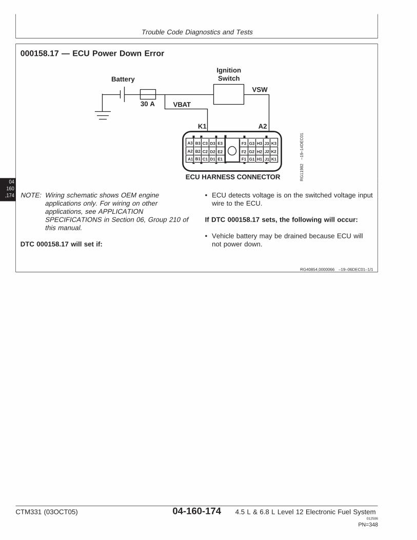
Trouble Code Diagnostics and Tests
04160,174
RG40854,0000066 –19–06DEC01–1/1
000158.17 — ECU Power Down Error
K1 A2
IgnitionSwitch
VSW
VBAT30 A
Battery
A1
A2
A3 B3 C3 D3 E3
B2 C2 D2 E2
B1 C1 D1 E1 F1
F2
F3 G3 H3 J3 K3
G2 H2 J2 K2
G1 H1 J1 K1
ECU HARNESS CONNECTOR RG
1198
2–1
9–14
DE
C01
NOTE: Wiring schematic shows OEM engineapplications only. For wiring on otherapplications, see APPLICATIONSPECIFICATIONS in Section 06, Group 210 ofthis manual.
DTC 000158.17 will set if:
• ECU detects voltage is on the switched voltage inputwire to the ECU.
If DTC 000158.17 sets, the following will occur:
• Vehicle battery may be drained because ECU willnot power down.
CTM331 (03OCT05) 04-160-174 4.5 L & 6.8 L Level 12 Electronic Fuel System012506
PN=348
Trouble Code Diagnostics and Tests
RG40854,0000109 –19–23SEP05–1/1
000158.17 — ECU Power Down Error
ECU detects voltage is on the switched voltage inputwire to the ECU.
04160,175
– – –1/1
000158.17 ECU Power Down Error Diagnostic Procedure
– – –1/1
1 Connection Check IMPORTANT: Do not force probes into connector terminals or damage will result.Use JT07328 Connector Adapter Test Kit to make measurements in connectors.This will ensure that terminal damage does not occur.
NOTE: For wiring and theory of operation information, see DTC 000158.17 ECUPOWER DOWN ERROR supporting information.
Perform a preliminary inspection of the ECU connector, ignition power circuit, and anyconnectors in between them. Look for dirty, damaged, or poorly positioned terminals.
No faulty connection(s):GO TO 2
Faulty connection(s):Repair faultyconnection(s)
– – –1/1
2 Intermittent Fault Test NOTE: For wiring and theory of operation information, see DTC 000158.17 ECUPOWER DOWN ERROR supporting information.
1. Connect to the DST or SERVICE ADVISOR.
2. Ignition ON, engine OFF
3. Start the ECU communication software
4. Read DTCs using the DST orSERVICE ADVISOR.
5. Make note of any DTCs, then clear all DTCs
6. Cycle ignition OFF for 10 seconds, then back ON
7. Read DTCs using the DST orSERVICE ADVISOR.
000158.17 reoccurs:GO TO 3
000158.17 does notreoccur:Problem is intermittent. Ifno other codes arepresent, seeINTERMITTENT FAULTDIAGNOSTICS earlier inthis Group.
SERVICE ADVISOR is a trademark of Deere & Company
CTM331 (03OCT05) 04-160-175 4.5 L & 6.8 L Level 12 Electronic Fuel System012506
PN=349
Trouble Code Diagnostics and Tests
04160,176
– – –1/1
3 Wiring Test NOTE: For wiring and theory of operation information, see DTC 000158.17 ECUPOWER DOWN ERROR supporting information.
1. Ignition OFF
2. Disconnect the ECU connector
3. Ignition ON, engine OFF
4. Using a multimeter, measure voltage between terminal A2 the ECU wiring harnessconnector and a good chassis ground.
Measurement above 3.0V:Faulty ignition switchcircuitORECU key-on power supplyshorted to voltageORFaulty ignition switch
Measurement below 3.0V:Faulty ECU connectionORFaulty ECU
CTM331 (03OCT05) 04-160-176 4.5 L & 6.8 L Level 12 Electronic Fuel System012506
PN=350

Trouble Code Diagnostics and Tests
04160,177
CTM331 (03OCT05) 04-160-177 4.5 L & 6.8 L Level 12 Electronic Fuel System012506
PN=351
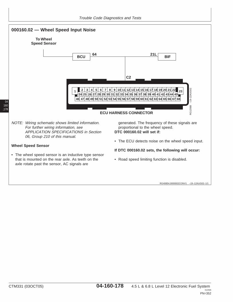
Trouble Code Diagnostics and Tests
04160,178
RG40854,0000002CONV1 –19–12AUG02–1/1
000160.02 — Wheel Speed Input Noise
21L64
To WheelSpeed Sensor
ECU HARNESS CONNECTOR
46 68
26 27 28 29 30 31 32 33 34 35 36 37 38 39 40 41 42 43 44 4524 252 3 4 5 6 7 8 9 10 11 12 13 14 15 16 17 18 19 20 21 22
47 48 49 50 51 52 53 54 55 56 57 58 59 60 61 62 63 64 65 66 67
1 23
BCU BIF
C2
RG
1258
8–1
9–22
AU
G02
NOTE: Wiring schematic shows limited information.For further wiring information, seeAPPLICATION SPECIFICATIONS in Section06, Group 210 of this manual.
Wheel Speed Sensor
• The wheel speed sensor is an inductive type sensorthat is mounted on the rear axle. As teeth on theaxle rotate past the sensor, AC signals are
generated. The frequency of these signals areproportional to the wheel speed.
DTC 000160.02 will set if:
• The ECU detects noise on the wheel speed input.
If DTC 000160.02 sets, the following will occur:
• Road speed limiting function is disabled.
CTM331 (03OCT05) 04-160-178 4.5 L & 6.8 L Level 12 Electronic Fuel System012506
PN=352
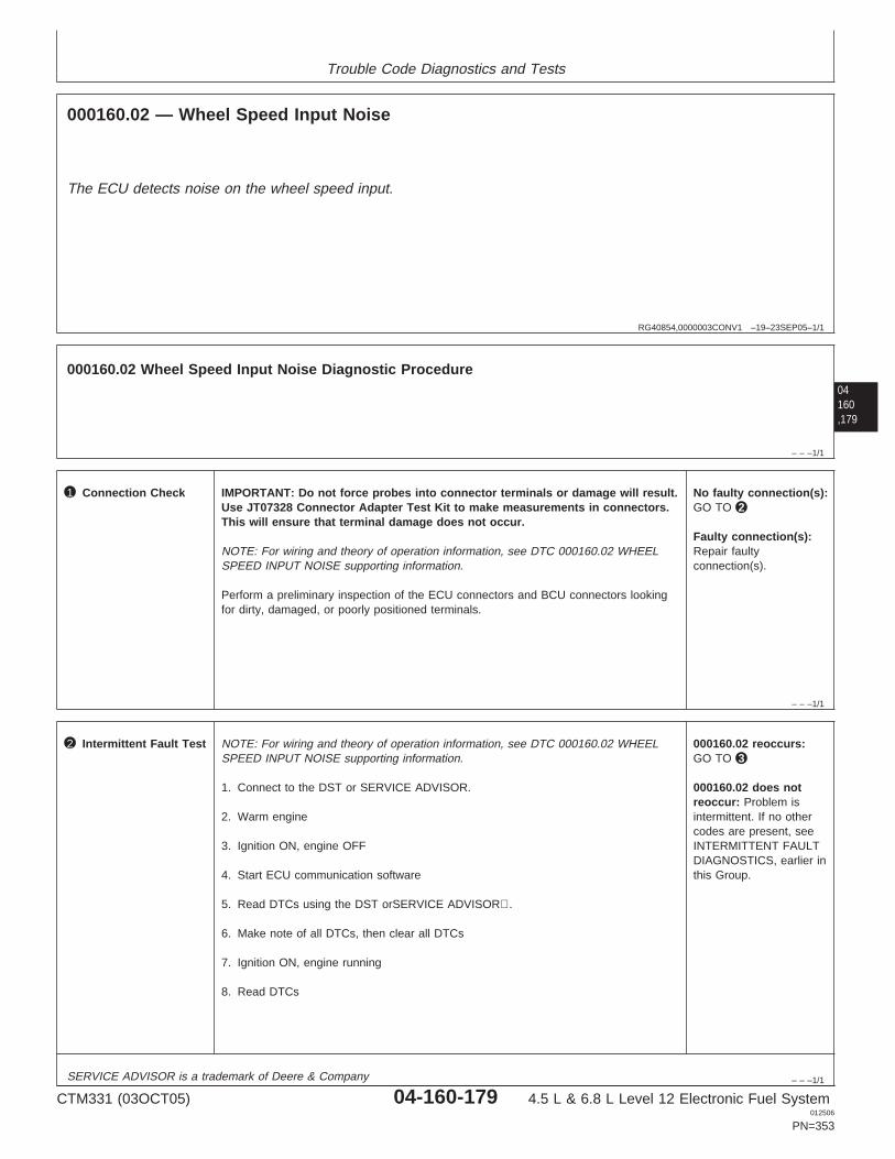
Trouble Code Diagnostics and Tests
RG40854,0000003CONV1 –19–23SEP05–1/1
000160.02 — Wheel Speed Input Noise
The ECU detects noise on the wheel speed input.
04160,179
– – –1/1
000160.02 Wheel Speed Input Noise Diagnostic Procedure
– – –1/1
1 Connection Check IMPORTANT: Do not force probes into connector terminals or damage will result.Use JT07328 Connector Adapter Test Kit to make measurements in connectors.This will ensure that terminal damage does not occur.
NOTE: For wiring and theory of operation information, see DTC 000160.02 WHEELSPEED INPUT NOISE supporting information.
Perform a preliminary inspection of the ECU connectors and BCU connectors lookingfor dirty, damaged, or poorly positioned terminals.
No faulty connection(s):GO TO 2
Faulty connection(s):Repair faultyconnection(s).
– – –1/1
2 Intermittent Fault Test NOTE: For wiring and theory of operation information, see DTC 000160.02 WHEELSPEED INPUT NOISE supporting information.
1. Connect to the DST or SERVICE ADVISOR.
2. Warm engine
3. Ignition ON, engine OFF
4. Start ECU communication software
5. Read DTCs using the DST orSERVICE ADVISOR.
6. Make note of all DTCs, then clear all DTCs
7. Ignition ON, engine running
8. Read DTCs
000160.02 reoccurs:GO TO 3
000160.02 does notreoccur: Problem isintermittent. If no othercodes are present, seeINTERMITTENT FAULTDIAGNOSTICS, earlier inthis Group.
SERVICE ADVISOR is a trademark of Deere & Company
CTM331 (03OCT05) 04-160-179 4.5 L & 6.8 L Level 12 Electronic Fuel System012506
PN=353
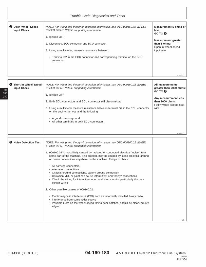
Trouble Code Diagnostics and Tests
– – –1/1
3 Open Wheel SpeedInput Check
NOTE: For wiring and theory of operation information, see DTC 000160.02 WHEELSPEED INPUT NOISE supporting information.
1. Ignition OFF
2. Disconnect ECU connector and BCU connector
3. Using a multimeter, measure resistance between:
• Terminal D2 in the ECU connector and corresponding terminal on the BCUconnector.
Measurement 5 ohms orless:GO TO 4
Measurement greaterthan 5 ohms:Open in wheel speedinput wire
04160,180
– – –1/1
4 Short in Wheel SpeedInput Check
NOTE: For wiring and theory of operation information, see DTC 000160.02 WHEELSPEED INPUT NOISE supporting information.
1. Ignition OFF
2. Both ECU connectors and BCU connector still disconnected
3. Using a multimeter measure resistance between terminal D2 in the ECU connectoron the engine harness and the following:
• A good chassis ground.• All other terminals in both ECU connectors.
All measurementsgreater than 2000 ohms:GO TO 5
Any measurement lessthan 2000 ohms:Faulty wheel speed inputwire
– – –1/1
5 Noise Detection Test NOTE: For wiring and theory of operation information, see DTC 000160.02 WHEELSPEED INPUT NOISE supporting information.
1. 000160.02 is most likely caused by radiated or conducted electrical "noise" fromsome part of the machine. This problem may be caused by loose electrical groundor power connections anywhere on the machine. Things to check:
• All harness connectors• Alternator connections• Chassis ground connections, battery ground connection• Corrosion, dirt, or paint can cause intermittent and "noisy" connections• Check the wiring for intermittent open and short circuits; particularly the cam
sensor wiring
2. Other possible causes of 000160.02:
• Electromagnetic interference (EMI) from an incorrectly installed 2-way radio• Interference from some radar source• Possible burrs on the wheel speed timing gear notches, should be clean, square
edges
CTM331 (03OCT05) 04-160-180 4.5 L & 6.8 L Level 12 Electronic Fuel System012506
PN=354

Trouble Code Diagnostics and Tests
04160,181
DB92450,000001F –19–03AUG05–1/1
000171.03 — Ambient Air Temperature Input Voltage Out Of Range High (750J Crawlersonly)
RG
1450
4–U
N–2
8SE
P05
Ambient Air Temperature Sensor Schematic
Ambient Air Temperature (AAT) Sensor
• The AAT sensor (C) is a thermistor (temperaturesensitive resistor) mounted in the intake air duct.The AAT sensor’s variable resistance causes theinput voltage to the ECU (A) to vary. Highertemperatures result in lower AAT input voltages tothe ECU; lower temperatures result in highervoltages. The AAT sensor is used by the ECU tocontrol the air heater in applications that use thisoptional feature.
DTC000171.03 will set if:
• The AAT input voltage exceeds the maximumthreshold. This voltage corresponds to a temperaturethat is lower than what is physically possible forambient air.
If DTC 000171.03 sets, the following will occur:
• No engine protection measures, nor other reactions,accompany this DTC.
CTM331 (03OCT05) 04-160-181 4.5 L & 6.8 L Level 12 Electronic Fuel System012506
PN=355
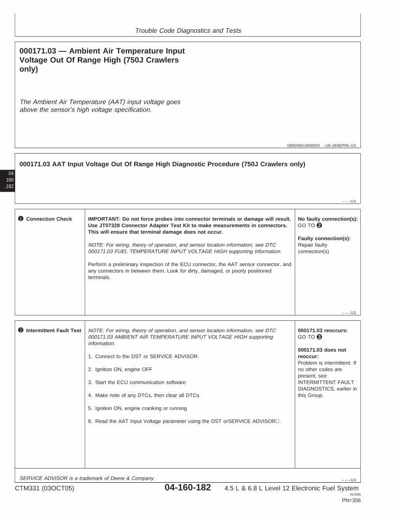
Trouble Code Diagnostics and Tests
DB92450,0000020 –19–26SEP05–1/1
000171.03 — Ambient Air Temperature InputVoltage Out Of Range High (750J Crawlersonly)
The Ambient Air Temperature (AAT) input voltage goesabove the sensor’s high voltage specification.
04160,182
– – –1/1
000171.03 AAT Input Voltage Out Of Range High Diagnostic Procedure (750J Crawlers only)
– – –1/1
1 Connection Check IMPORTANT: Do not force probes into connector terminals or damage will result.Use JT07328 Connector Adapter Test Kit to make measurements in connectors.This will ensure that terminal damage does not occur.
NOTE: For wiring, theory of operation, and sensor location information, see DTC000171.03 FUEL TEMPERATURE INPUT VOLTAGE HIGH supporting information.
Perform a preliminary inspection of the ECU connector, the AAT sensor connector, andany connectors in between them. Look for dirty, damaged, or poorly positionedterminals.
No faulty connection(s):GO TO 2
Faulty connection(s):Repair faultyconnection(s)
– – –1/1
2 Intermittent Fault Test NOTE: For wiring, theory of operation, and sensor location information, see DTC000171.03 AMBIENT AIR TEMPERATURE INPUT VOLTAGE HIGH supportinginformation.
1. Connect to the DST or SERVICE ADVISOR.
2. Ignition ON, engine OFF
3. Start the ECU communication software
4. Make note of any DTCs, then clear all DTCs.
5. Ignition ON, engine cranking or running
6. Read the AAT Input Voltage parameter using the DST orSERVICE ADVISOR.
000171.03 reoccurs:GO TO 3
000171.03 does notreoccur:Problem is intermittent. Ifno other codes arepresent, seeINTERMITTENT FAULTDIAGNOSTICS, earlier inthis Group.
SERVICE ADVISOR is a trademark of Deere & Company
CTM331 (03OCT05) 04-160-182 4.5 L & 6.8 L Level 12 Electronic Fuel System012506
PN=356
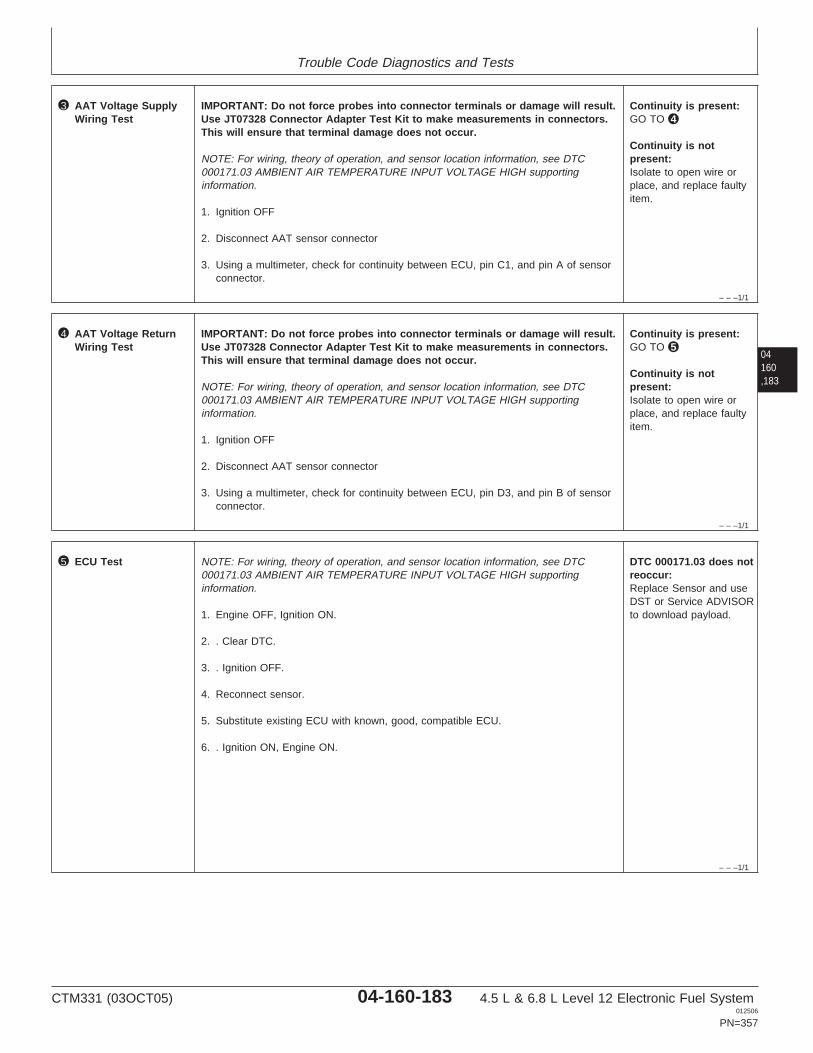
Trouble Code Diagnostics and Tests
– – –1/1
3 AAT Voltage SupplyWiring Test
IMPORTANT: Do not force probes into connector terminals or damage will result.Use JT07328 Connector Adapter Test Kit to make measurements in connectors.This will ensure that terminal damage does not occur.
NOTE: For wiring, theory of operation, and sensor location information, see DTC000171.03 AMBIENT AIR TEMPERATURE INPUT VOLTAGE HIGH supportinginformation.
1. Ignition OFF
2. Disconnect AAT sensor connector
3. Using a multimeter, check for continuity between ECU, pin C1, and pin A of sensorconnector.
Continuity is present:GO TO 4
Continuity is notpresent:Isolate to open wire orplace, and replace faultyitem.
04160,183
– – –1/1
4 AAT Voltage ReturnWiring Test
IMPORTANT: Do not force probes into connector terminals or damage will result.Use JT07328 Connector Adapter Test Kit to make measurements in connectors.This will ensure that terminal damage does not occur.
NOTE: For wiring, theory of operation, and sensor location information, see DTC000171.03 AMBIENT AIR TEMPERATURE INPUT VOLTAGE HIGH supportinginformation.
1. Ignition OFF
2. Disconnect AAT sensor connector
3. Using a multimeter, check for continuity between ECU, pin D3, and pin B of sensorconnector.
Continuity is present:GO TO 5
Continuity is notpresent:Isolate to open wire orplace, and replace faultyitem.
– – –1/1
5 ECU Test NOTE: For wiring, theory of operation, and sensor location information, see DTC000171.03 AMBIENT AIR TEMPERATURE INPUT VOLTAGE HIGH supportinginformation.
1. Engine OFF, Ignition ON.
2. . Clear DTC.
3. . Ignition OFF.
4. Reconnect sensor.
5. Substitute existing ECU with known, good, compatible ECU.
6. . Ignition ON, Engine ON.
DTC 000171.03 does notreoccur:Replace Sensor and useDST or Service ADVISORto download payload.
CTM331 (03OCT05) 04-160-183 4.5 L & 6.8 L Level 12 Electronic Fuel System012506
PN=357
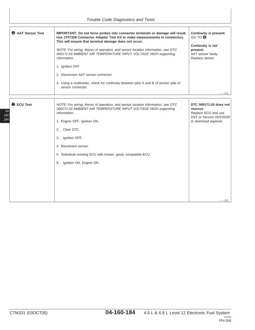
Trouble Code Diagnostics and Tests
– – –1/1
6 AAT Sensor Test IMPORTANT: Do not force probes into connector terminals or damage will result.Use JT07328 Connector Adapter Test Kit to make measurements in connectors.This will ensure that terminal damage does not occur.
NOTE: For wiring, theory of operation, and sensor location information, see DTC000171.03 AMBIENT AIR TEMPERATURE INPUT VOLTAGE HIGH supportinginformation.
1. Ignition OFF
2. Disconnect AAT sensor connector
3. Using a multimeter, check for continuity between pins A and B of sensor side ofsensor connector.
Continuity is present:GO TO 6
Continuity is notpresent:AAT sensor faulty.Replace sensor
04160,184
– – –1/1
7 ECU Test NOTE: For wiring, theory of operation, and sensor location information, see DTC000171.03 AMBIENT AIR TEMPERATURE INPUT VOLTAGE HIGH supportinginformation.
1. Engine OFF, Ignition ON.
2. . Clear DTC.
3. . Ignition OFF.
4. Reconnect sensor.
5. Substitute existing ECU with known, good, compatible ECU.
6. . Ignition ON, Engine ON.
DTC 000171.03 does notreoccur:Replace ECU and useDST or Service ADVISORto download payload.
CTM331 (03OCT05) 04-160-184 4.5 L & 6.8 L Level 12 Electronic Fuel System012506
PN=358
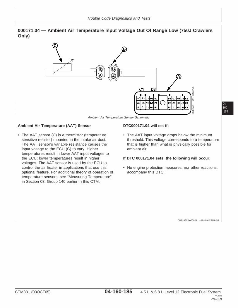
Trouble Code Diagnostics and Tests
04160,185
DB92450,0000021 –19–04OCT05–1/1
000171.04 — Ambient Air Temperature Input Voltage Out Of Range Low (750J CrawlersOnly)
RG
1450
4–U
N–2
8SE
P05
Ambient Air Temperature Sensor Schematic
Ambient Air Temperature (AAT) Sensor
• The AAT sensor (C) is a thermistor (temperaturesensitive resistor) mounted in the intake air duct.The AAT sensor’s variable resistance causes theinput voltage to the ECU (C) to vary. Highertemperatures result in lower AAT input voltages tothe ECU; lower temperatures result in highervoltages. The AAT sensor is used by the ECU tocontrol the air heater in applications that use thisoptional feature. For additional theory of operation oftemperature sensors, see “Measuring Temperature”,in Section 03, Group 140 earlier in this CTM.
DTC000171.04 will set if:
• The AAT input voltage drops below the minimumthreshold. This voltage corresponds to a temperaturethat is higher than what is physically possible forambient air.
If DTC 000171.04 sets, the following will occur:
• No engine protection measures, nor other reactions,accompany this DTC.
CTM331 (03OCT05) 04-160-185 4.5 L & 6.8 L Level 12 Electronic Fuel System012506
PN=359
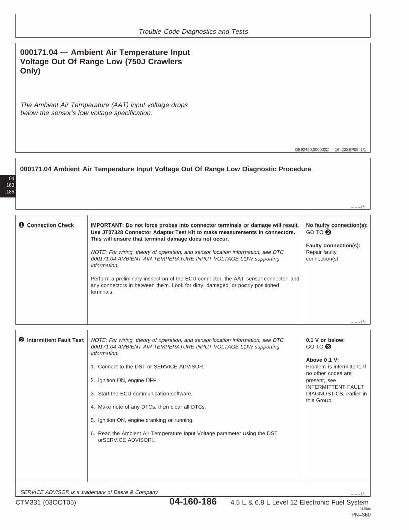
Trouble Code Diagnostics and Tests
DB92450,0000022 –19–23SEP05–1/1
000171.04 — Ambient Air Temperature InputVoltage Out Of Range Low (750J CrawlersOnly)
The Ambient Air Temperature (AAT) input voltage dropsbelow the sensor’s low voltage specification.
04160,186
– – –1/1
000171.04 Ambient Air Temperature Input Voltage Out Of Range Low Diagnostic Procedure
– – –1/1
1 Connection Check IMPORTANT: Do not force probes into connector terminals or damage will result.Use JT07328 Connector Adapter Test Kit to make measurements in connectors.This will ensure that terminal damage does not occur.
NOTE: For wiring, theory of operation, and sensor location information, see DTC000171.04 AMBIENT AIR TEMPERATURE INPUT VOLTAGE LOW supportinginformation.
Perform a preliminary inspection of the ECU connector, the AAT sensor connector, andany connectors in between them. Look for dirty, damaged, or poorly positionedterminals.
No faulty connection(s):GO TO 2
Faulty connection(s):Repair faultyconnection(s)
– – –1/1
2 Intermittent Fault Test NOTE: For wiring, theory of operation, and sensor location information, see DTC000171.04 AMBIENT AIR TEMPERATURE INPUT VOLTAGE LOW supportinginformation.
1. Connect to the DST or SERVICE ADVISOR.
2. Ignition ON, engine OFF.
3. Start the ECU communication software.
4. Make note of any DTCs, then clear all DTCs.
5. Ignition ON, engine cranking or running.
6. Read the Ambient Air Temperature Input Voltage parameter using the DSTorSERVICE ADVISOR
0.1 V or below:GO TO 3
Above 0.1 V:Problem is intermittent. Ifno other codes arepresent, seeINTERMITTENT FAULTDIAGNOSTICS, earlier inthis Group.
SERVICE ADVISOR is a trademark of Deere & Company
CTM331 (03OCT05) 04-160-186 4.5 L & 6.8 L Level 12 Electronic Fuel System012506
PN=360
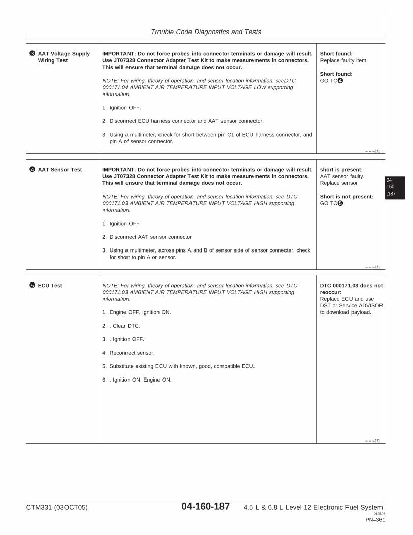
Trouble Code Diagnostics and Tests
– – –1/1
3 AAT Voltage SupplyWiring Test
IMPORTANT: Do not force probes into connector terminals or damage will result.Use JT07328 Connector Adapter Test Kit to make measurements in connectors.This will ensure that terminal damage does not occur.
NOTE: For wiring, theory of operation, and sensor location information, seeDTC000171.04 AMBIENT AIR TEMPERATURE INPUT VOLTAGE LOW supportinginformation.
1. Ignition OFF.
2. Disconnect ECU harness connector and AAT sensor connector.
3. Using a multimeter, check for short between pin C1 of ECU harness connector, andpin A of sensor connector.
Short found:Replace faulty item
Short found:GO TO 4
04160,187
– – –1/1
4 AAT Sensor Test IMPORTANT: Do not force probes into connector terminals or damage will result.Use JT07328 Connector Adapter Test Kit to make measurements in connectors.This will ensure that terminal damage does not occur.
NOTE: For wiring, theory of operation, and sensor location information, see DTC000171.03 AMBIENT AIR TEMPERATURE INPUT VOLTAGE HIGH supportinginformation.
1. Ignition OFF
2. Disconnect AAT sensor connector
3. Using a multimeter, across pins A and B of sensor side of sensor connecter, checkfor short to pin A or sensor.
short is present:AAT sensor faulty.Replace sensor
Short is not present:GO TO 5
– – –1/1
5 ECU Test NOTE: For wiring, theory of operation, and sensor location information, see DTC000171.03 AMBIENT AIR TEMPERATURE INPUT VOLTAGE HIGH supportinginformation.
1. Engine OFF, Ignition ON.
2. . Clear DTC.
3. . Ignition OFF.
4. Reconnect sensor.
5. Substitute existing ECU with known, good, compatible ECU.
6. . Ignition ON, Engine ON.
DTC 000171.03 does notreoccur:Replace ECU and useDST or Service ADVISORto download payload.
CTM331 (03OCT05) 04-160-187 4.5 L & 6.8 L Level 12 Electronic Fuel System012506
PN=361

Trouble Code Diagnostics and Tests
04160,188
RG40854,0000062 –19–07SEP05–1/1
000174.03 — Fuel Temperature Input Voltage High
C3
A A
BB
D3
Fuel TempConnector
Fuel TempSensor
Sensor Ground
Fuel Temp Input
t
A1
A2
A3 B3 C3 D3 E3
B2 C2 D2 E2
B1 C1 D1 E1 F1
F2
F3 G3 H3 J3 K3
G2 H2 J2 K2
G1 H1 J1 K1
ECU HARNESS CONNECTOR RG
1198
8–1
9–08
JAN
02
NOTE: Wiring schematic shows OEM engineapplications only. For wiring on otherapplications, see APPLICATIONSPECIFICATIONS in Section 06, Group 210 ofthis manual.
Fuel Temperature Sensor
• The fuel temperature sensor is a thermistor(temperature sensitive resistor) located on theinjection pump fuel outlet housing. The fueltemperature sensor’s variable resistance causes theinput voltage to the ECU to vary. Higher fueltemperatures result in lower fuel temperature inputvoltages to the ECU; lower temperatures result inhigher voltages. The ECU uses the fuel temperaturesensor input to adjust the fuel delivery for thevariations in fuel density caused by varying fueltemperatures. For more fuel temperature sensorinformation, see MEASURING TEMPERATURE inSection 03, Group 140 of this manual.
DTC 000174.03 will set if:
• The fuel temperature input voltage goes above thesensor’s high voltage specification. This voltagecorresponds to a temperature that is lower than whatis physically possible for fuel temperature.– For OEM engine applications, the high fuel
temperature input voltage specification is 4.9volts.
– For other applications, see APPLICATIONSPECIFICATIONS in Section 06, Group 210 ofthis manual for the high fuel temperature inputvoltage specification.
If DTC 000174.03 sets, the following will occur:
• The ECU will use a "limp-home" fuel temperaturevalue of -20°C (-4°F) during cranking, and 40°C(104°F) during running.
• Engine power will be slightly derated.
CTM331 (03OCT05) 04-160-188 4.5 L & 6.8 L Level 12 Electronic Fuel System012506
PN=362
Trouble Code Diagnostics and Tests
RG40854,00000F3 –19–23SEP05–1/1
000174.03 — Fuel Temperature Input Voltage High
The fuel temperature input voltage goes above thesensor’s high voltage specification.
04160,189
– – –1/1
000174.03 Fuel Temperature Input Voltage High Diagnostic Procedure
– – –1/1
1 Connection Check IMPORTANT: Do not force probes into connector terminals or damage will result.Use JT07328 Connector Adapter Test Kit to make measurements in connectors.This will ensure that terminal damage does not occur.
NOTE: For wiring, theory of operation, and sensor location information, see DTC000174.03 FUEL TEMPERATURE INPUT VOLTAGE HIGH supporting information.
Perform a preliminary inspection of the ECU connector, the fuel temperature sensorconnector, and any connectors in between them. Look for dirty, damaged, or poorlypositioned terminals.
No faulty connection(s):GO TO 2
Faulty connection(s):Repair faultyconnection(s)
– – –1/1
2 Intermittent Fault Test NOTE: For wiring, theory of operation, and sensor location information, see DTC000174.03 FUEL TEMPERATURE INPUT VOLTAGE HIGH supporting information.
1. Connect to the DST or SERVICE ADVISOR.
2. Ignition ON, engine OFF
3. Start the ECU communication software
4. Ignition ON, engine running
5. Read the Fuel Temperature Input Voltage parameter using the DST orSERVICEADVISOR.
NOTE: On OEM applications, the high fuel temperature input voltage specification is4.9 volts and above. For fuel temperature input voltage specifications on otherapplications, see APPLICATION SPECIFICATIONS in Section 06, Group 210 of thismanual.
4.9 V or greater:GO TO 3
Below 4.9 V:Problem is intermittent. Ifno other codes arepresent, seeINTERMITTENT FAULTDIAGNOSTICS, earlier inthis Group.
SERVICE ADVISOR is a trademark of Deere & Company
CTM331 (03OCT05) 04-160-189 4.5 L & 6.8 L Level 12 Electronic Fuel System012506
PN=363
Trouble Code Diagnostics and Tests
04160,190
– – –1/1
3 Fuel TemperatureSensor andConnector Test
NOTE: For wiring, theory of operation, and sensor location information, see DTC000174.03 FUEL TEMPERATURE INPUT VOLTAGE HIGH supporting information.
1. Ignition OFF
2. Disconnect fuel temperature sensor connector
3. Install a jumper wire between both terminals in the fuel temperature sensor harnessconnector
4. Ignition ON, engine OFF
5. Read the Fuel Temperature Input Voltage parameter using the DST or SERVICEADVISOR.
NOTE: On OEM applications, the low fuel temperature input voltage specification is0.1 volts and below. For fuel temperature input voltage specifications on otherapplications, see APPLICATION SPECIFICATIONS in Section 06, Group 210 of thismanual.
Above 0.1 V:GO TO 4
At or below 0.1 V:Faulty fuel temperaturesensor connectorORFaulty fuel temperaturesensor
– – –1/1
4 Fuel TemperatureOpen Ground Test
NOTE: For wiring, theory of operation, and sensor location information, see DTC000174.03 FUEL TEMPERATURE INPUT VOLTAGE HIGH supporting information.
1. Ignition OFF
2. Remove jumper wire between both terminals
3. Install jumper wire between fuel temperature sensor harness connector inputterminal and a good chassis ground
4. Ignition ON, engine OFF
5. Read the Fuel Temperature Input Voltage parameter using the DST or SERVICEADVISOR.
NOTE: On OEM applications, the low fuel temperature input voltage specification is0.1 volts and below. For fuel temperature input voltage specifications on otherapplications, see APPLICATION SPECIFICATIONS in Section 06, Group 210 of thismanual.
Above 0.1 V:Open in fuel temperatureinput sensor circuitORFaulty ECU connectionORFaulty ECU
0.1 V or below:Open in fuel temperaturesensor ground circuitORFaulty ECU connectionORFaulty ECU
CTM331 (03OCT05) 04-160-190 4.5 L & 6.8 L Level 12 Electronic Fuel System012506
PN=364

Trouble Code Diagnostics and Tests
04160,191
CTM331 (03OCT05) 04-160-191 4.5 L & 6.8 L Level 12 Electronic Fuel System012506
PN=365
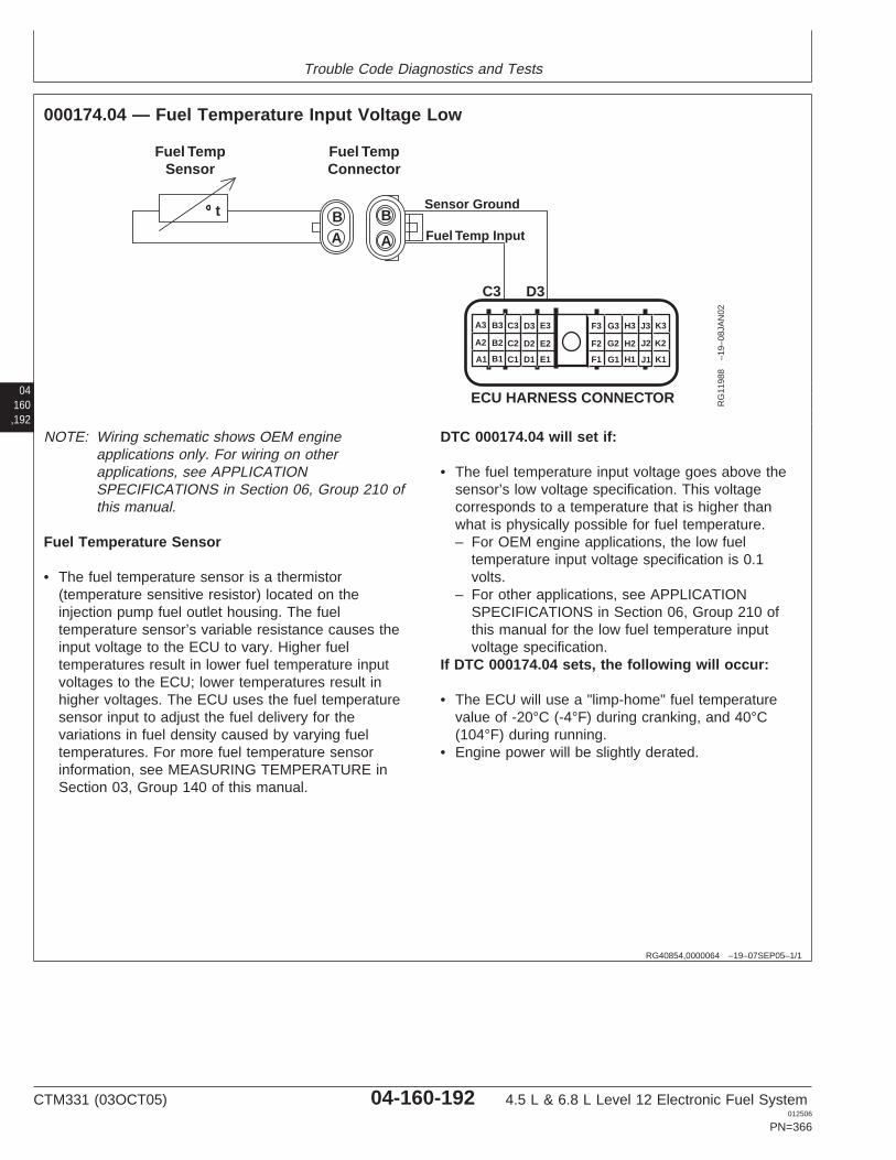
Trouble Code Diagnostics and Tests
04160,192
RG40854,0000064 –19–07SEP05–1/1
000174.04 — Fuel Temperature Input Voltage Low
C3
A A
BB
D3
Fuel TempConnector
Fuel TempSensor
Sensor Ground
Fuel Temp Input
t
A1
A2
A3 B3 C3 D3 E3
B2 C2 D2 E2
B1 C1 D1 E1 F1
F2
F3 G3 H3 J3 K3
G2 H2 J2 K2
G1 H1 J1 K1
ECU HARNESS CONNECTOR RG
1198
8–1
9–08
JAN
02
NOTE: Wiring schematic shows OEM engineapplications only. For wiring on otherapplications, see APPLICATIONSPECIFICATIONS in Section 06, Group 210 ofthis manual.
Fuel Temperature Sensor
• The fuel temperature sensor is a thermistor(temperature sensitive resistor) located on theinjection pump fuel outlet housing. The fueltemperature sensor’s variable resistance causes theinput voltage to the ECU to vary. Higher fueltemperatures result in lower fuel temperature inputvoltages to the ECU; lower temperatures result inhigher voltages. The ECU uses the fuel temperaturesensor input to adjust the fuel delivery for thevariations in fuel density caused by varying fueltemperatures. For more fuel temperature sensorinformation, see MEASURING TEMPERATURE inSection 03, Group 140 of this manual.
DTC 000174.04 will set if:
• The fuel temperature input voltage goes above thesensor’s low voltage specification. This voltagecorresponds to a temperature that is higher thanwhat is physically possible for fuel temperature.– For OEM engine applications, the low fuel
temperature input voltage specification is 0.1volts.
– For other applications, see APPLICATIONSPECIFICATIONS in Section 06, Group 210 ofthis manual for the low fuel temperature inputvoltage specification.
If DTC 000174.04 sets, the following will occur:
• The ECU will use a "limp-home" fuel temperaturevalue of -20°C (-4°F) during cranking, and 40°C(104°F) during running.
• Engine power will be slightly derated.
CTM331 (03OCT05) 04-160-192 4.5 L & 6.8 L Level 12 Electronic Fuel System012506
PN=366

Trouble Code Diagnostics and Tests
RG40854,00000F2 –19–23SEP05–1/1
000174.04 — Fuel Temperature Input Voltage Low
The fuel temperature input voltage goes above thesensor’s low voltage specification.
04160,193
– – –1/1
000174.04 Fuel Temperature Input Voltage Low Diagnostic Procedure
– – –1/1
1 Connection Check IMPORTANT: Do not force probes into connector terminals or damage will result.Use JT07328 Connector Adapter Test Kit to make measurements in connectors.This will ensure that terminal damage does not occur.
NOTE: For wiring, theory of operation, and sensor location information, see DTC000174.04 FUEL TEMPERATURE INPUT VOLTAGE LOW supporting information.
Perform a preliminary inspection of the ECU connector, the fuel temperature sensorconnector, and any connectors in between them. Look for dirty, damaged, or poorlypositioned terminals.
No faulty connection(s):GO TO 2
Faulty connection(s):Repair faultyconnection(s)
– – –1/1
2 Intermittent Fault Test NOTE: For wiring, theory of operation, and sensor location information, see DTC000174.04 FUEL TEMPERATURE INPUT VOLTAGE LOW supporting information.
1. Connect to the DST or SERVICE ADVISOR.
2. Ignition ON, engine OFF
3. Start the ECU communication software
4. Ignition ON, engine OFF
5. Read the Fuel Temperature Input Voltage parameter using the DST orSERVICEADVISOR
NOTE: For OEM engine applications, the low fuel temperature input voltagespecification is 0.1V. For the low voltage specification on other applications, seeAPPLICATION SPECIFICATIONS in Section 06, Group 210 of this manual.
0.1 V or below:GO TO 3
Above 0.1 V:Problem is intermittent. Ifno other codes arepresent, seeINTERMITTENT FAULTDIAGNOSTICS, earlier inthis Group.
SERVICE ADVISOR is a trademark of Deere & Company
CTM331 (03OCT05) 04-160-193 4.5 L & 6.8 L Level 12 Electronic Fuel System012506
PN=367
Trouble Code Diagnostics and Tests
04160,194
– – –1/1
3 Fuel TemperatureSensor Test
NOTE: For wiring, theory of operation, and sensor location information, seeDTC000174.04 FUEL TEMPERATURE INPUT VOLTAGE LOW supporting information.
1. Ignition OFF
2. Disconnect fuel temperature sensor connector
3. Ignition ON
4. Read the Fuel Temperature Input Voltage parameter using the DST or SERVICEADVISOR.
NOTE: For OEM engine applications, the high fuel temperature input voltagespecification is 4.9V. For the high voltage specification on other applications, seeAPPLICATION SPECIFICATIONS in Section 06, Group 210 of this manual.
Below 4.9 V:Short to ground in fueltemperature sensor inputcircuitORFaulty ECU
4.9 V or greater:Faulty fuel temperaturesensor
CTM331 (03OCT05) 04-160-194 4.5 L & 6.8 L Level 12 Electronic Fuel System012506
PN=368

Trouble Code Diagnostics and Tests
04160,195
CTM331 (03OCT05) 04-160-195 4.5 L & 6.8 L Level 12 Electronic Fuel System012506
PN=369
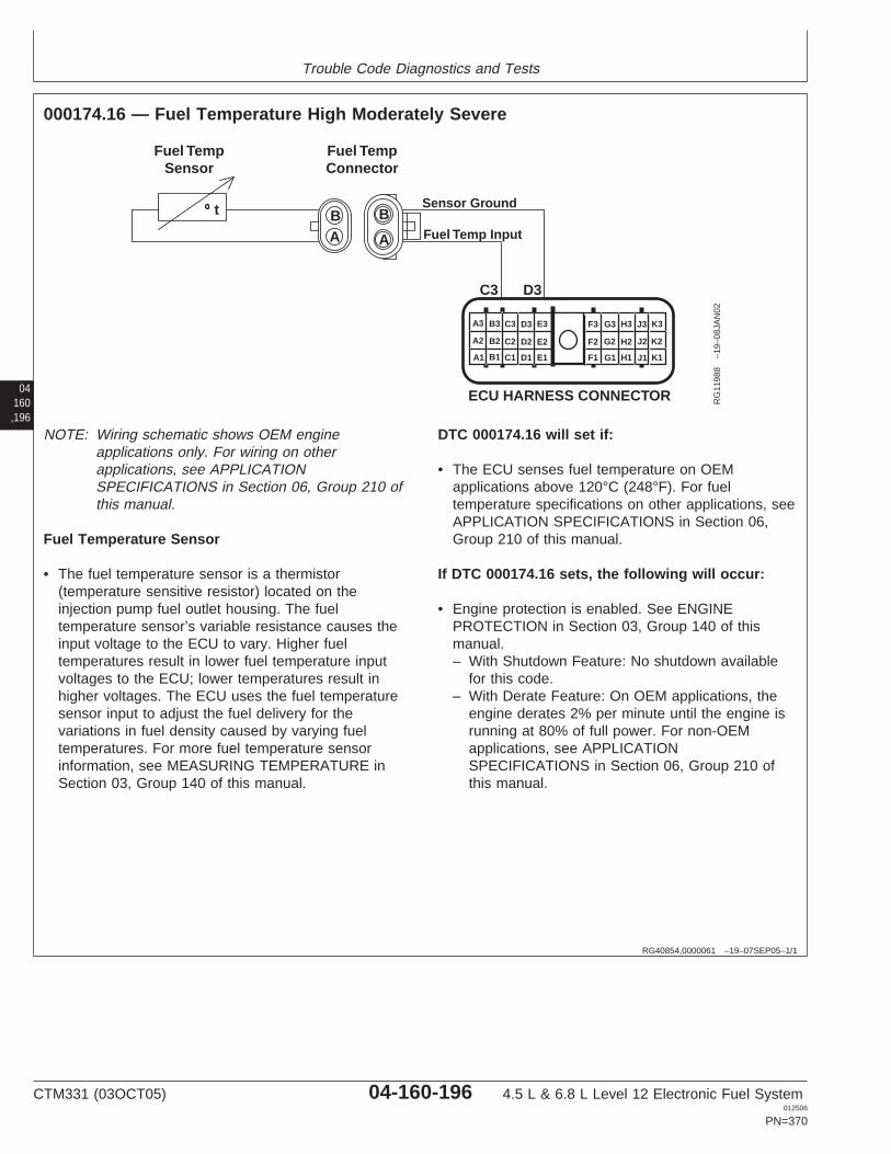
Trouble Code Diagnostics and Tests
04160,196
RG40854,0000061 –19–07SEP05–1/1
000174.16 — Fuel Temperature High Moderately Severe
C3
A A
BB
D3
Fuel TempConnector
Fuel TempSensor
Sensor Ground
Fuel Temp Input
t
A1
A2
A3 B3 C3 D3 E3
B2 C2 D2 E2
B1 C1 D1 E1 F1
F2
F3 G3 H3 J3 K3
G2 H2 J2 K2
G1 H1 J1 K1
ECU HARNESS CONNECTOR RG
1198
8–1
9–08
JAN
02
NOTE: Wiring schematic shows OEM engineapplications only. For wiring on otherapplications, see APPLICATIONSPECIFICATIONS in Section 06, Group 210 ofthis manual.
Fuel Temperature Sensor
• The fuel temperature sensor is a thermistor(temperature sensitive resistor) located on theinjection pump fuel outlet housing. The fueltemperature sensor’s variable resistance causes theinput voltage to the ECU to vary. Higher fueltemperatures result in lower fuel temperature inputvoltages to the ECU; lower temperatures result inhigher voltages. The ECU uses the fuel temperaturesensor input to adjust the fuel delivery for thevariations in fuel density caused by varying fueltemperatures. For more fuel temperature sensorinformation, see MEASURING TEMPERATURE inSection 03, Group 140 of this manual.
DTC 000174.16 will set if:
• The ECU senses fuel temperature on OEMapplications above 120°C (248°F). For fueltemperature specifications on other applications, seeAPPLICATION SPECIFICATIONS in Section 06,Group 210 of this manual.
If DTC 000174.16 sets, the following will occur:
• Engine protection is enabled. See ENGINEPROTECTION in Section 03, Group 140 of thismanual.– With Shutdown Feature: No shutdown available
for this code.– With Derate Feature: On OEM applications, the
engine derates 2% per minute until the engine isrunning at 80% of full power. For non-OEMapplications, see APPLICATIONSPECIFICATIONS in Section 06, Group 210 ofthis manual.
CTM331 (03OCT05) 04-160-196 4.5 L & 6.8 L Level 12 Electronic Fuel System012506
PN=370
Trouble Code Diagnostics and Tests
RG40854,00000F5 –19–07SEP05–1/1
000174.16 — Fuel Temperature High Moderately Severe
The ECU senses fuel temperature abovespecifications.
04160,197
– – –1/1
000174.16 Fuel Temperature High Moderately Severe Diagnostic Procedure
– – –1/1
1 DTC 000174.16Preliminary Check
Before using this diagnostic procedure:
1. Ensure that the fuel level in the fuel tank is not extremely low
2. Ensure that fuel cooler is clean
No problems found:GO TO 2
Problem found:Repair and retest
– – –1/1
2 Connection Check IMPORTANT: Do not force probes into connector terminals or damage will result.Use JT07328 Connector Adapter Test Kit to make measurements in connectors.This will ensure that terminal damage does not occur.
NOTE: For wiring and theory of operation information, see DTC 000174.16 FUELTEMPERATURE HIGH MODERATELY SEVERE supporting information
Perform a preliminary inspection of the ECU connector, the fuel temperature sensorconnector, and any connectors in between them. Look for dirty, damaged, or poorlypositioned terminals.
No faulty connection(s):GO TO 3
Faulty connection(s):Repair faultyconnection(s)
CTM331 (03OCT05) 04-160-197 4.5 L & 6.8 L Level 12 Electronic Fuel System012506
PN=371
Trouble Code Diagnostics and Tests
04160,198
– – –1/1
3 Fuel Supply PressureCheck
NOTE: For wiring and theory of operation information, see DTC 000174.16 FUELTEMPERATURE HIGH MODERATELY SEVERE supporting information
Determine fuel supply pressure. See CHECK FUEL SUPPLY PRESSURE in Section04, Group 150 of this manual.
Fuel pressure withinspecification:GO TO 4
Fuel pressure belowspecification:Determine cause of lowfuel supply pressure. SeeF1 - FUEL SUPPLYSYSTEM CHECKDIAGNOSTICPROCEDURE in Section04, Group 150 of thismanual.Repair and retest.
– – –1/1
4 Fuel Return LinesRestriction Check
NOTE: For wiring and theory of operation information, see DTC 000174.16 FUELTEMPERATURE HIGH MODERATELY SEVERE supporting information
Check return fuel lines for restriction between fuel tank and:
• Overflow valve on injection pump• Fuel leak off line at injection nozzles
Fuel return lines NOTrestricted:Faulty fuel coolerORFaulty injection pump
Restriction found ineither fuel return line:Determine the cause ofrestrictionRepair and retest
CTM331 (03OCT05) 04-160-198 4.5 L & 6.8 L Level 12 Electronic Fuel System012506
PN=372
Trouble Code Diagnostics and Tests
04160,199
RG40854,0000001 –19–12AUG02–1/1
000189.00 — Engine Speed Derate
The ECU detects a condition that requires an enginespeed derate.
Engine Speed Derate
• The engine speed derate trouble code is set toindicate that the ECU has detected a condition orcode such as DTC 002000.13 that requires enginespeed to be limited.
DTC 000189.00 will set if:
• The ECU detects a condition that requires an enginespeed derate.
If DTC 000189.00 sets, the following will occur:
• The ECU will limit engine speed in an attempt toprotect the engine.
If DTC 000189.00 sets:
• Check for other stored or active DTCs that indicatethe reason for the speed derate.
CTM331 (03OCT05) 04-160-199 4.5 L & 6.8 L Level 12 Electronic Fuel System012506
PN=373
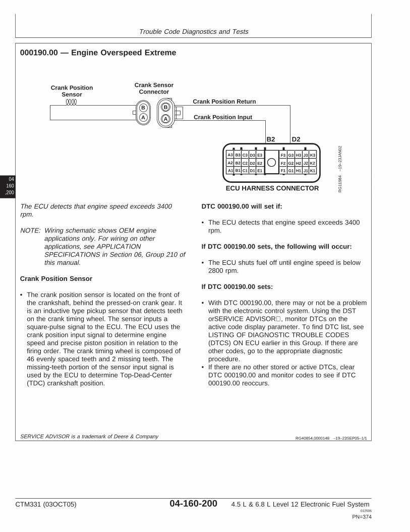
Trouble Code Diagnostics and Tests
04160,200
RG40854,0000148 –19–23SEP05–1/1
000190.00 — Engine Overspeed Extreme
Crank Position Input
Crank Position Return
Crank PositionSensor
Crank SensorConnector
A
B
A
B
B2 D2
A1
A2
A3 B3 C3 D3 E3
B2 C2 D2 E2
B1 C1 D1 E1 F1
F2
F3 G3 H3 J3 K3
G2 H2 J2 K2
G1 H1 J1 K1
ECU HARNESS CONNECTOR RG
1198
4–1
9–23
JAN
02
The ECU detects that engine speed exceeds 3400rpm.
NOTE: Wiring schematic shows OEM engineapplications only. For wiring on otherapplications, see APPLICATIONSPECIFICATIONS in Section 06, Group 210 ofthis manual.
Crank Position Sensor
• The crank position sensor is located on the front ofthe crankshaft, behind the pressed-on crank gear. Itis an inductive type pickup sensor that detects teethon the crank timing wheel. The sensor inputs asquare-pulse signal to the ECU. The ECU uses thecrank position input signal to determine enginespeed and precise piston position in relation to thefiring order. The crank timing wheel is composed of46 evenly spaced teeth and 2 missing teeth. Themissing-teeth portion of the sensor input signal isused by the ECU to determine Top-Dead-Center(TDC) crankshaft position.
DTC 000190.00 will set if:
• The ECU detects that engine speed exceeds 3400rpm.
If DTC 000190.00 sets, the following will occur:
• The ECU shuts fuel off until engine speed is below2800 rpm.
If DTC 000190.00 sets:
• With DTC 000190.00, there may or not be a problemwith the electronic control system. Using the DSTorSERVICE ADVISOR, monitor DTCs on theactive code display parameter. To find DTC list, seeLISTING OF DIAGNOSTIC TROUBLE CODES(DTCS) ON ECU earlier in this Group. If there areother codes, go to the appropriate diagnosticprocedure.
• If there are no other stored or active DTCs, clearDTC 000190.00 and monitor codes to see if DTC000190.00 reoccurs.
SERVICE ADVISOR is a trademark of Deere & Company
CTM331 (03OCT05) 04-160-200 4.5 L & 6.8 L Level 12 Electronic Fuel System012506
PN=374
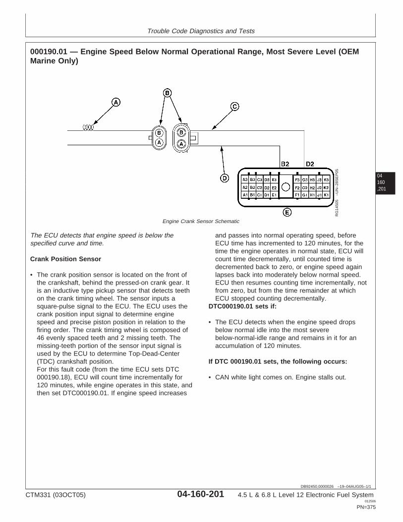
Trouble Code Diagnostics and Tests
04160,201
DB92450,0000026 –19–04AUG05–1/1
000190.01 — Engine Speed Below Normal Operational Range, Most Severe Level (OEMMarine Only)
RG
1450
5–U
N–2
8SE
P05
Engine Crank Sensor Schematic
The ECU detects that engine speed is below thespecified curve and time.
Crank Position Sensor
• The crank position sensor is located on the front ofthe crankshaft, behind the pressed-on crank gear. Itis an inductive type pickup sensor that detects teethon the crank timing wheel. The sensor inputs asquare-pulse signal to the ECU. The ECU uses thecrank position input signal to determine enginespeed and precise piston position in relation to thefiring order. The crank timing wheel is composed of46 evenly spaced teeth and 2 missing teeth. Themissing-teeth portion of the sensor input signal isused by the ECU to determine Top-Dead-Center(TDC) crankshaft position.For this fault code (from the time ECU sets DTC000190.18), ECU will count time incrementally for120 minutes, while engine operates in this state, andthen set DTC000190.01. If engine speed increases
and passes into normal operating speed, beforeECU time has incremented to 120 minutes, for thetime the engine operates in normal state, ECU willcount time decrementally, until counted time isdecremented back to zero, or engine speed againlapses back into moderately below normal speed.ECU then resumes counting time incrementally, notfrom zero, but from the time remainder at whichECU stopped counting decrementally.
DTC000190.01 sets if:
• The ECU detects when the engine speed dropsbelow normal idle into the most severebelow-normal-idle range and remains in it for anaccumulation of 120 minutes.
If DTC 000190.01 sets, the following occurs:
• CAN white light comes on. Engine stalls out.
CTM331 (03OCT05) 04-160-201 4.5 L & 6.8 L Level 12 Electronic Fuel System012506
PN=375
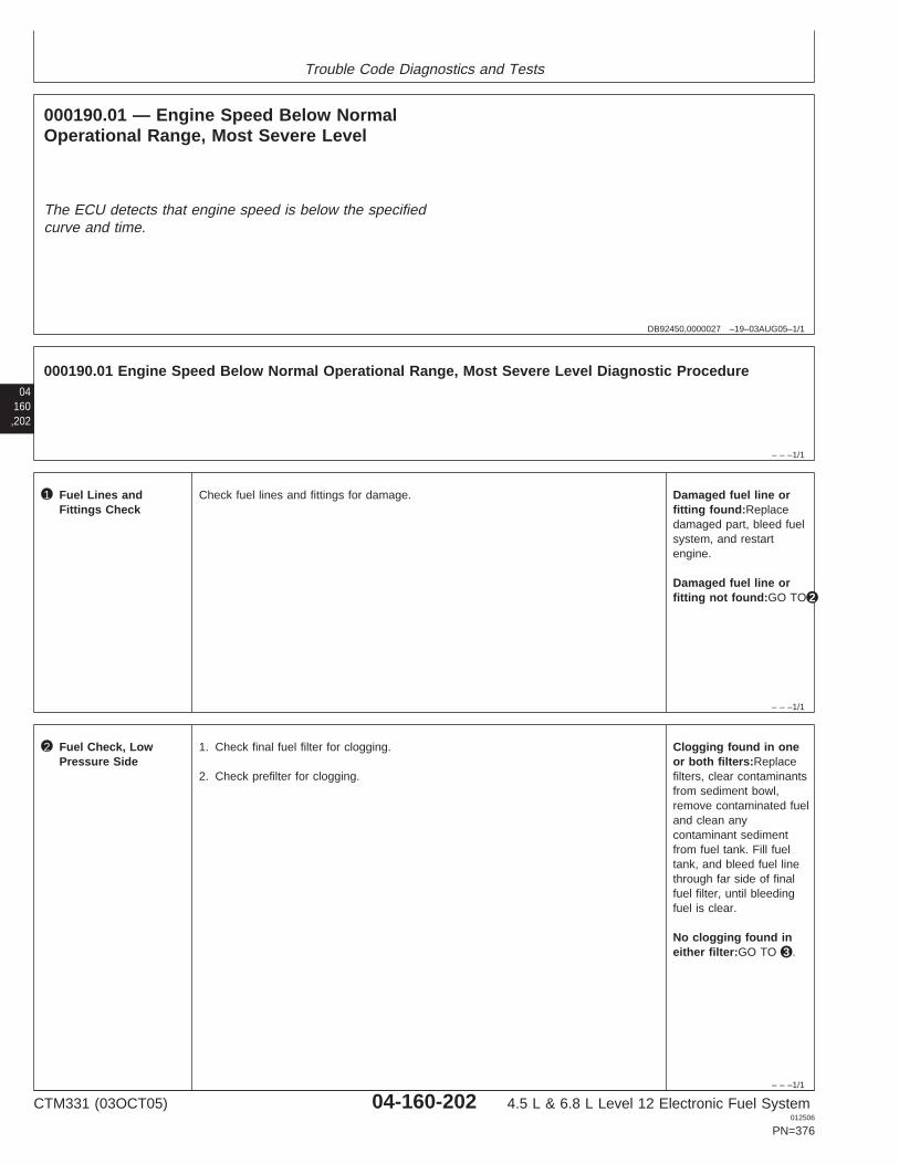
Trouble Code Diagnostics and Tests
DB92450,0000027 –19–03AUG05–1/1
000190.01 — Engine Speed Below NormalOperational Range, Most Severe Level
The ECU detects that engine speed is below the specifiedcurve and time.
04160,202
– – –1/1
000190.01 Engine Speed Below Normal Operational Range, Most Severe Level Diagnostic Procedure
– – –1/1
1 Fuel Lines andFittings Check
Check fuel lines and fittings for damage. Damaged fuel line orfitting found:Replacedamaged part, bleed fuelsystem, and restartengine.
Damaged fuel line orfitting not found:GO TO 2
– – –1/1
2 Fuel Check, LowPressure Side
1. Check final fuel filter for clogging.
2. Check prefilter for clogging.
Clogging found in oneor both filters:Replacefilters, clear contaminantsfrom sediment bowl,remove contaminated fueland clean anycontaminant sedimentfrom fuel tank. Fill fueltank, and bleed fuel linethrough far side of finalfuel filter, until bleedingfuel is clear.
No clogging found ineither filter:GO TO 3 .
CTM331 (03OCT05) 04-160-202 4.5 L & 6.8 L Level 12 Electronic Fuel System012506
PN=376
Trouble Code Diagnostics and Tests
04160,203
– – –1/1
3 Transfer Pump Check IMPORTANT: A backup wrench must always be used when loosening andtightening fittings of fuel lines from and to supply pump to avoid damage tofittings.
1.At fuel line from transfer pump to final fuel filter, loosen tube nut fitting at fuel filterend sufficiently to allow fuel to be freely bled from it.
2. Depending on type of transfer pump, electrically or manually operate pump.
IMPORTANT: A backup wrench must always be used when loosening andtightening fittings of fuel lines from and to supply pump to avoid damage tofittings.
3.Check to see whether or not fuel is steadily bleeding out.
Fuel is steadily bleedingout:Close fitting, Tightento specifications.
SpecificationTube Nut—Torque 24 N•m (18 lb-ft)..................................................................................
Restart engine.
Fuel is not bleedingout:Remove and replacepump. Tighten tospecifications.
SpecificationTube Nut—Torque 24 N•m (18 lb-ft)..................................................................................
Bleed fuel system.Restart engine.
CTM331 (03OCT05) 04-160-203 4.5 L & 6.8 L Level 12 Electronic Fuel System012506
PN=377

Trouble Code Diagnostics and Tests
04160,204
RG40854,0000149 –19–23SEP05–1/1
000190.16 — Engine Overspeed Moderate
Crank Position Input
Crank Position Return
Crank PositionSensor
Crank SensorConnector
A
B
A
B
B2 D2
A1
A2
A3 B3 C3 D3 E3
B2 C2 D2 E2
B1 C1 D1 E1 F1
F2
F3 G3 H3 J3 K3
G2 H2 J2 K2
G1 H1 J1 K1
ECU HARNESS CONNECTOR RG
1198
4–1
9–23
JAN
02
The ECU detects that engine speed is higher than3000 rpm.
NOTE: Wiring schematic shows OEM engineapplications only. For wiring on otherapplications, see APPLICATIONSPECIFICATIONS in Section 06, Group 210 ofthis manual.
Crank Position Sensor
• The crank position sensor is located on the front ofthe crankshaft, behind the pressed-on crank gear. Itis an inductive type pickup sensor that detects teethon the crank timing wheel. The sensor inputs asquare-pulse signal to the ECU. The ECU uses thecrank position input signal to determine enginespeed and precise piston position in relation to thefiring order. The crank timing wheel is composed of46 evenly spaced teeth and 2 missing teeth. Themissing-teeth portion of the sensor input signal isused by the ECU to determine Top-Dead-Center(TDC) crankshaft position.
DTC 000190.16 will set if:
• The ECU detects that engine speed is higher than3000 rpm.
If DTC 000190.16 sets, the following will occur:
• The ECU shuts fuel off until engine speed is below2800 rpm.
If DTC 000190.16 sets:
• With DTC 000190.16, there may or not be a problemwith the electronic control system. Using the DSTorSERVICE ADVISOR, monitor DTCs on theactive code display parameter. To find DTC list, seeLISTING OF DIAGNOSTIC TROUBLE CODES(DTCS) ON ECU earlier in this Group. If there areother codes, go to the appropriate diagnosticprocedure.
• If there are no other stored or active DTCs, clearDTC 000190.16 and monitor codes to see if DTC000190.16 reoccurs.
SERVICE ADVISOR is a trademark of Deere & Company
CTM331 (03OCT05) 04-160-204 4.5 L & 6.8 L Level 12 Electronic Fuel System012506
PN=378
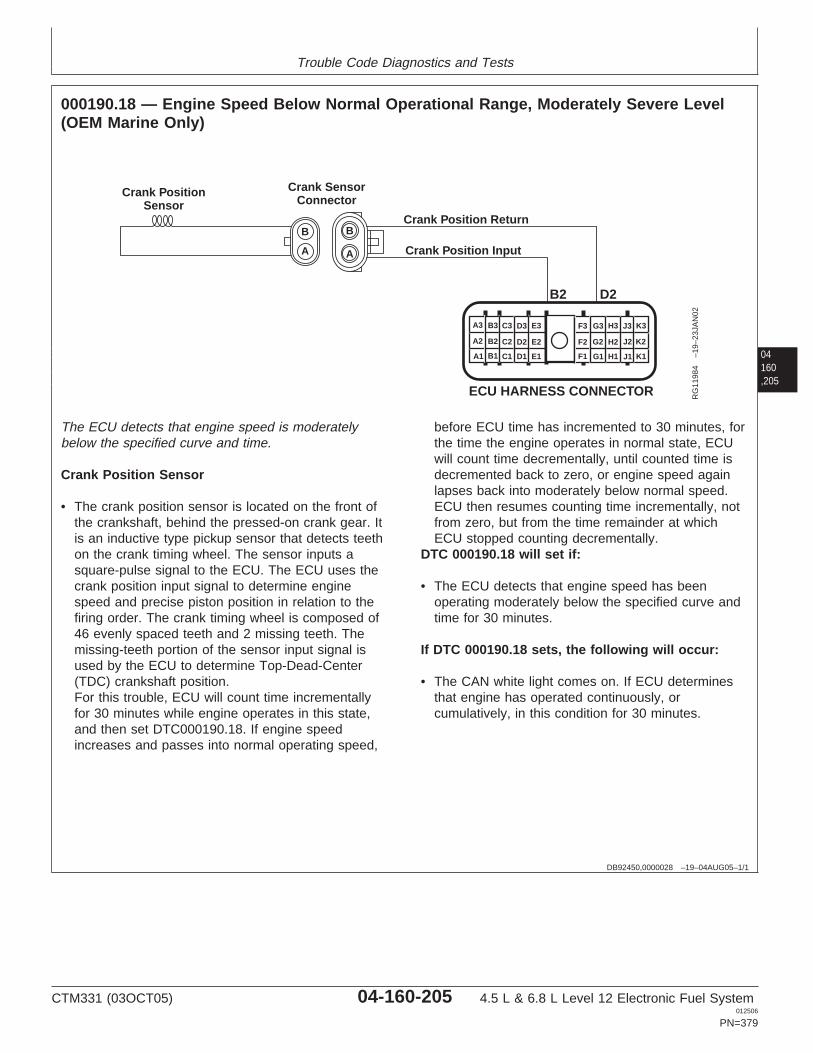
Trouble Code Diagnostics and Tests
04160,205
DB92450,0000028 –19–04AUG05–1/1
000190.18 — Engine Speed Below Normal Operational Range, Moderately Severe Level(OEM Marine Only)
Crank Position Input
Crank Position Return
Crank PositionSensor
Crank SensorConnector
A
B
A
B
B2 D2
A1
A2
A3 B3 C3 D3 E3
B2 C2 D2 E2
B1 C1 D1 E1 F1
F2
F3 G3 H3 J3 K3
G2 H2 J2 K2
G1 H1 J1 K1
ECU HARNESS CONNECTOR RG
1198
4–1
9–23
JAN
02
The ECU detects that engine speed is moderatelybelow the specified curve and time.
Crank Position Sensor
• The crank position sensor is located on the front ofthe crankshaft, behind the pressed-on crank gear. Itis an inductive type pickup sensor that detects teethon the crank timing wheel. The sensor inputs asquare-pulse signal to the ECU. The ECU uses thecrank position input signal to determine enginespeed and precise piston position in relation to thefiring order. The crank timing wheel is composed of46 evenly spaced teeth and 2 missing teeth. Themissing-teeth portion of the sensor input signal isused by the ECU to determine Top-Dead-Center(TDC) crankshaft position.For this trouble, ECU will count time incrementallyfor 30 minutes while engine operates in this state,and then set DTC000190.18. If engine speedincreases and passes into normal operating speed,
before ECU time has incremented to 30 minutes, forthe time the engine operates in normal state, ECUwill count time decrementally, until counted time isdecremented back to zero, or engine speed againlapses back into moderately below normal speed.ECU then resumes counting time incrementally, notfrom zero, but from the time remainder at whichECU stopped counting decrementally.
DTC 000190.18 will set if:
• The ECU detects that engine speed has beenoperating moderately below the specified curve andtime for 30 minutes.
If DTC 000190.18 sets, the following will occur:
• The CAN white light comes on. If ECU determinesthat engine has operated continuously, orcumulatively, in this condition for 30 minutes.
CTM331 (03OCT05) 04-160-205 4.5 L & 6.8 L Level 12 Electronic Fuel System012506
PN=379
Trouble Code Diagnostics and Tests
04160,206
DB92450,0000029 –19–05AUG05–1/1
000523.09 — Current Gear Selection Invalidor Not Received (J-series Loaders Only)
ECU is receiving invalid selection information for currentgear, or is receiving no information at all.
Gear Selection
• The Loader controller transmits the vehicle gearselection to the ECU over the CAN bus. The ECU usesthis information to select the correct governor curvemode.
DTC 000523.09 will set if:
• The ECU does not receive vehicle gear selectioninformation, or the information ECU receives is invalid.
If DTC 000523.09 Sets:
• The ECU does not receive vehicle gear selectioninformation, or it is invalid
• Transport curve cannot be selected. (Only one torquecurve is used for this machine. No timers or deratetorque curves are used.
• Using the DST or SERVICE ADVISOR, monitor DTCson the active code display parameter.
• Check to see if any other controllers on the machinehave any active or stored CAN or vehicle-related DTCs.If they do, go to the appropriate diagnostic procedure.
• If no other stored or active CAN or vehicle related DTCsare found, replace ECU and retest.
NOTE: For diagnostic troubleshooting procedure, refer tothe Loader Vehicle Technical Manual.
CTM331 (03OCT05) 04-160-206 4.5 L & 6.8 L Level 12 Electronic Fuel System012506
PN=380

Trouble Code Diagnostics and Tests
04160,207
CTM331 (03OCT05) 04-160-207 4.5 L & 6.8 L Level 12 Electronic Fuel System012506
PN=381
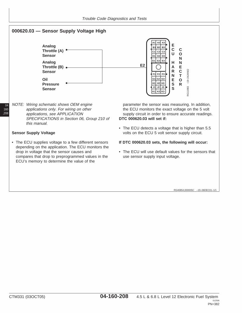
Trouble Code Diagnostics and Tests
04160,208
RG40854,000005C –19–06DEC01–1/1
000620.03 — Sensor Supply Voltage High
OilPressureSensor
AnalogThrottle (A)Sensor
AnalogThrottle (B)Sensor
E2
A1 A2 A3
B3
C3
D3
E3
B2
C2
D2
E2
B1
C1
D1
E1
F1 F2 F3
G3
H3
J3
K3
G2
H2
J2
K2
G1
H1
J1
K1
ECU
HARNESS
CONNECTOR
RG
1198
3–1
9–24
JAN
02
NOTE: Wiring schematic shows OEM engineapplications only. For wiring on otherapplications, see APPLICATIONSPECIFICATIONS in Section 06, Group 210 ofthis manual.
Sensor Supply Voltage
• The ECU supplies voltage to a few different sensorsdepending on the application. The ECU monitors thedrop in voltage that the sensor causes andcompares that drop to preprogrammed values in theECU’s memory to determine the value of the
parameter the sensor was measuring. In addition,the ECU monitors the exact voltage on the 5 voltsupply circuit in order to ensure accurate readings.
DTC 000620.03 will set if:
• The ECU detects a voltage that is higher than 5.5volts on the ECU 5 volt sensor supply circuit.
If DTC 000620.03 sets, the following will occur:
• The ECU will use default values for the sensors thatuse sensor supply input voltage.
CTM331 (03OCT05) 04-160-208 4.5 L & 6.8 L Level 12 Electronic Fuel System012506
PN=382

Trouble Code Diagnostics and Tests
RG40854,00000F6 –19–23SEP05–1/1
000620.03 — Sensor Supply Voltage High
The ECU detects a voltage that is higher than 5.5 voltson the ECU 5 volt sensor supply circuit.
04160,209
– – –1/1
000620.03 Sensor Supply Voltage High Diagnostic Procedure
– – –1/1
1 Connection Check IMPORTANT: Do not force probes into connector terminals or damage will result.Use JT07328 Connector Adapter Test Kit to make measurements in connectors.This will ensure that terminal damage does not occur.
NOTE: For wiring and theory of operation information, see DTC 000620.03 SENSORSUPPLY VOLTAGE HIGH supporting information.
Perform a preliminary inspection of the ECU connector. Look for dirty, damaged, orpoorly positioned terminals.
No faulty connection(s):GO TO 2
Faulty connection(s):Repair faultyconnection(s)
– – –1/1
2 Intermittent Fault Test NOTE: For wiring and theory of operation information, see DTC 000620.03 SENSORSUPPLY VOLTAGE HIGH supporting information.
1. Connect to the DST or SERVICE ADVISOR.
2. Ignition ON, engine OFF
3. Start the ECU communication software
4. Read DTCs using the DST orSERVICE ADVISOR.
5. Make note of any DTCs, then clear all DTCs
6. Ignition ON, engine OFF
7. Read DTCs using the DST orSERVICE ADVISOR.
000620.03 reoccurs:GO TO 3
000620.03 does notreoccur:Problem is intermittent. Ifno other codes arepresent, seeINTERMITTENT FAULTDIAGNOSTICS, earlier inthis Group.
SERVICE ADVISOR is a trademark of Deere & Company
CTM331 (03OCT05) 04-160-209 4.5 L & 6.8 L Level 12 Electronic Fuel System012506
PN=383
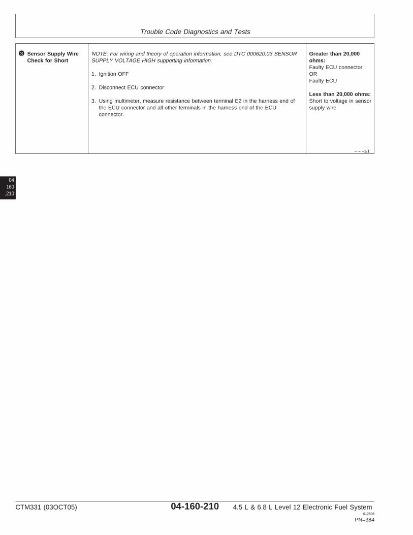
Trouble Code Diagnostics and Tests
– – –1/1
3 Sensor Supply WireCheck for Short
NOTE: For wiring and theory of operation information, see DTC 000620.03 SENSORSUPPLY VOLTAGE HIGH supporting information.
1. Ignition OFF
2. Disconnect ECU connector
3. Using multimeter, measure resistance between terminal E2 in the harness end ofthe ECU connector and all other terminals in the harness end of the ECUconnector.
Greater than 20,000ohms:Faulty ECU connectorORFaulty ECU
Less than 20,000 ohms:Short to voltage in sensorsupply wire
04160,210
CTM331 (03OCT05) 04-160-210 4.5 L & 6.8 L Level 12 Electronic Fuel System012506
PN=384

Trouble Code Diagnostics and Tests
04160,211
CTM331 (03OCT05) 04-160-211 4.5 L & 6.8 L Level 12 Electronic Fuel System012506
PN=385

Trouble Code Diagnostics and Tests
04160,212
RG40854,000005E –19–06DEC01–1/1
000620.04 — Sensor Supply Voltage Low
OilPressureSensor
AnalogThrottle (A)Sensor
AnalogThrottle (B)Sensor
E2
A1 A2 A3
B3
C3
D3
E3
B2
C2
D2
E2
B1
C1
D1
E1
F1 F2 F3
G3
H3
J3
K3
G2
H2
J2
K2
G1
H1
J1
K1
ECU
HARNESS
CONNECTOR
RG
1198
3–1
9–24
JAN
02
NOTE: Wiring schematic shows OEM engineapplications only. For wiring on otherapplications, see APPLICATIONSPECIFICATIONS in Section 06, Group 210 ofthis manual.
Sensor Supply Voltage
• The ECU supplies voltage to a few different sensorsdepending on the application. The ECU monitors thedrop in voltage that the sensor causes andcompares that drop to preprogrammed values in theECU’s memory to determine the value of the
parameter the sensor was measuring. In addition,the ECU monitors the exact voltage on the 5 voltsupply circuit in order to ensure accurate readings.
DTC 000620.04 will set if:
• The ECU detects a voltage that is lower than 4.44volts on the ECU 5 volt sensor supply circuit.
If DTC 000620.04 sets, the following will occur:
• The ECU will use default values for the sensors thatuse sensor supply input voltage.
CTM331 (03OCT05) 04-160-212 4.5 L & 6.8 L Level 12 Electronic Fuel System012506
PN=386
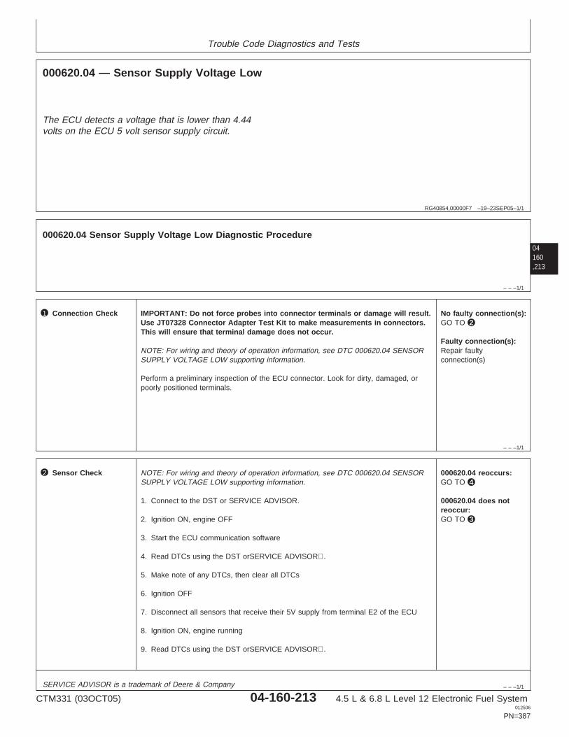
Trouble Code Diagnostics and Tests
RG40854,00000F7 –19–23SEP05–1/1
000620.04 — Sensor Supply Voltage Low
The ECU detects a voltage that is lower than 4.44volts on the ECU 5 volt sensor supply circuit.
04160,213
– – –1/1
000620.04 Sensor Supply Voltage Low Diagnostic Procedure
– – –1/1
1 Connection Check IMPORTANT: Do not force probes into connector terminals or damage will result.Use JT07328 Connector Adapter Test Kit to make measurements in connectors.This will ensure that terminal damage does not occur.
NOTE: For wiring and theory of operation information, see DTC 000620.04 SENSORSUPPLY VOLTAGE LOW supporting information.
Perform a preliminary inspection of the ECU connector. Look for dirty, damaged, orpoorly positioned terminals.
No faulty connection(s):GO TO 2
Faulty connection(s):Repair faultyconnection(s)
– – –1/1
2 Sensor Check NOTE: For wiring and theory of operation information, see DTC 000620.04 SENSORSUPPLY VOLTAGE LOW supporting information.
1. Connect to the DST or SERVICE ADVISOR.
2. Ignition ON, engine OFF
3. Start the ECU communication software
4. Read DTCs using the DST orSERVICE ADVISOR.
5. Make note of any DTCs, then clear all DTCs
6. Ignition OFF
7. Disconnect all sensors that receive their 5V supply from terminal E2 of the ECU
8. Ignition ON, engine running
9. Read DTCs using the DST orSERVICE ADVISOR.
000620.04 reoccurs:GO TO 4
000620.04 does notreoccur:GO TO 3
SERVICE ADVISOR is a trademark of Deere & Company
CTM331 (03OCT05) 04-160-213 4.5 L & 6.8 L Level 12 Electronic Fuel System012506
PN=387
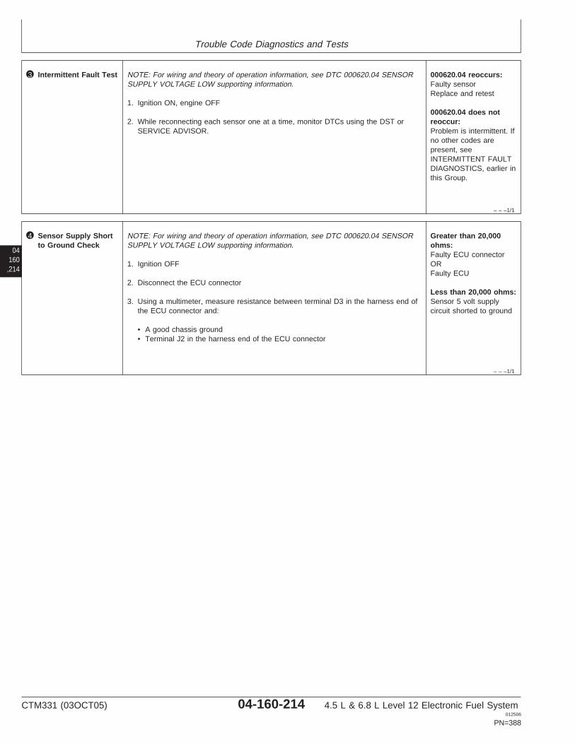
Trouble Code Diagnostics and Tests
– – –1/1
3 Intermittent Fault Test NOTE: For wiring and theory of operation information, see DTC 000620.04 SENSORSUPPLY VOLTAGE LOW supporting information.
1. Ignition ON, engine OFF
2. While reconnecting each sensor one at a time, monitor DTCs using the DST orSERVICE ADVISOR.
000620.04 reoccurs:Faulty sensorReplace and retest
000620.04 does notreoccur:Problem is intermittent. Ifno other codes arepresent, seeINTERMITTENT FAULTDIAGNOSTICS, earlier inthis Group.
04160,214
– – –1/1
4 Sensor Supply Shortto Ground Check
NOTE: For wiring and theory of operation information, see DTC 000620.04 SENSORSUPPLY VOLTAGE LOW supporting information.
1. Ignition OFF
2. Disconnect the ECU connector
3. Using a multimeter, measure resistance between terminal D3 in the harness end ofthe ECU connector and:
• A good chassis ground• Terminal J2 in the harness end of the ECU connector
Greater than 20,000ohms:Faulty ECU connectorORFaulty ECU
Less than 20,000 ohms:Sensor 5 volt supplycircuit shorted to ground
CTM331 (03OCT05) 04-160-214 4.5 L & 6.8 L Level 12 Electronic Fuel System012506
PN=388

Trouble Code Diagnostics and Tests
04160,215
CTM331 (03OCT05) 04-160-215 4.5 L & 6.8 L Level 12 Electronic Fuel System012506
PN=389
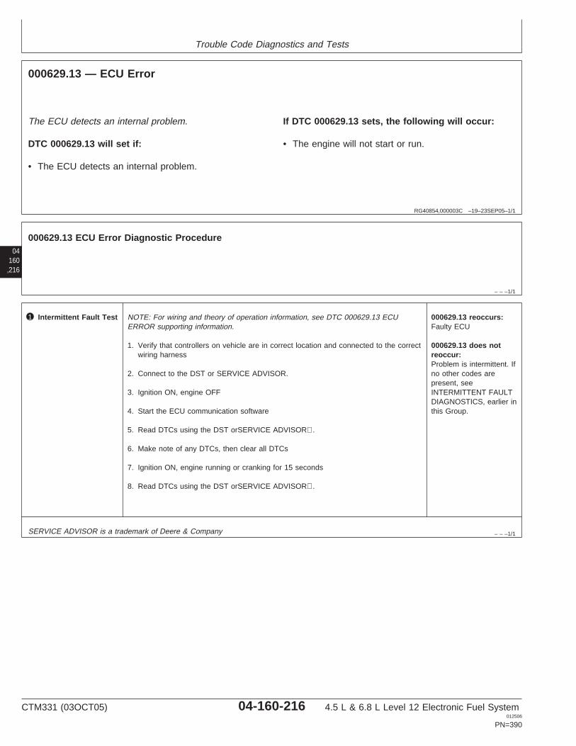
Trouble Code Diagnostics and Tests
RG40854,000003C –19–23SEP05–1/1
000629.13 — ECU Error
The ECU detects an internal problem.
DTC 000629.13 will set if:
• The ECU detects an internal problem.
If DTC 000629.13 sets, the following will occur:
• The engine will not start or run.
04160,216
– – –1/1
000629.13 ECU Error Diagnostic Procedure
– – –1/1
1 Intermittent Fault Test NOTE: For wiring and theory of operation information, see DTC 000629.13 ECUERROR supporting information.
1. Verify that controllers on vehicle are in correct location and connected to the correctwiring harness
2. Connect to the DST or SERVICE ADVISOR.
3. Ignition ON, engine OFF
4. Start the ECU communication software
5. Read DTCs using the DST orSERVICE ADVISOR.
6. Make note of any DTCs, then clear all DTCs
7. Ignition ON, engine running or cranking for 15 seconds
8. Read DTCs using the DST orSERVICE ADVISOR.
000629.13 reoccurs:Faulty ECU
000629.13 does notreoccur:Problem is intermittent. Ifno other codes arepresent, seeINTERMITTENT FAULTDIAGNOSTICS, earlier inthis Group.
SERVICE ADVISOR is a trademark of Deere & Company
CTM331 (03OCT05) 04-160-216 4.5 L & 6.8 L Level 12 Electronic Fuel System012506
PN=390

Trouble Code Diagnostics and Tests
04160,217
CTM331 (03OCT05) 04-160-217 4.5 L & 6.8 L Level 12 Electronic Fuel System012506
PN=391
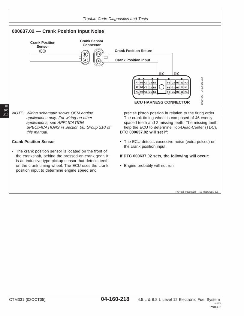
Trouble Code Diagnostics and Tests
04160,218
RG40854,0000038 –19–06DEC01–1/1
000637.02 — Crank Position Input Noise
Crank Position Input
Crank Position Return
Crank PositionSensor
Crank SensorConnector
A
B
A
B
B2 D2
A1
A2
A3 B3 C3 D3 E3
B2 C2 D2 E2
B1 C1 D1 E1 F1
F2
F3 G3 H3 J3 K3
G2 H2 J2 K2
G1 H1 J1 K1
ECU HARNESS CONNECTOR RG
1198
4–1
9–23
JAN
02
NOTE: Wiring schematic shows OEM engineapplications only. For wiring on otherapplications, see APPLICATIONSPECIFICATIONS in Section 06, Group 210 ofthis manual.
Crank Position Sensor
• The crank position sensor is located on the front ofthe crankshaft, behind the pressed-on crank gear. Itis an inductive type pickup sensor that detects teethon the crank timing wheel. The ECU uses the crankposition input to determine engine speed and
precise piston position in relation to the firing order.The crank timing wheel is composed of 46 evenlyspaced teeth and 2 missing teeth. The missing teethhelp the ECU to determine Top-Dead-Center (TDC).
DTC 000637.02 will set if:
• The ECU detects excessive noise (extra pulses) onthe crank position input.
If DTC 000637.02 sets, the following will occur:
• Engine probably will not run
CTM331 (03OCT05) 04-160-218 4.5 L & 6.8 L Level 12 Electronic Fuel System012506
PN=392
Trouble Code Diagnostics and Tests
RG40854,00000F8 –19–23SEP05–1/1
000637.02 — Crank Position Input Noise
The ECU detects excessive noise (extra pulses) on thecrank position input.
04160,219
– – –1/1
000637.02 Crank Position Input Noise Diagnostic Procedure
– – –1/1
1 Connection Check IMPORTANT: Do not force probes into connector terminals or damage will result.Use JT07328 Connector Adapter Test Kit to make measurements in connectors.This will ensure that terminal damage does not occur.
NOTE: For wiring and theory of operation information, see DTC 000637.02 CRANKPOSITION INPUT NOISE supporting information.
Perform a preliminary inspection of the ECU connector, the crank position sensorconnector, and any other connector. Look for dirty, damaged, or poorly positionedterminals.
No faulty connection(s):GO TO 2
Faulty connection(s):Repair faultyconnection(s)
– – –1/1
2 Intermittent Fault Test NOTE: For wiring and theory of operation information, see DTC 000637.02 CRANKPOSITION INPUT NOISE supporting information.
1. Connect to the DST or SERVICE ADVISOR.
2. Ignition ON, engine OFF
3. Start the ECU communication software
4. Read DTCs using the DST orSERVICE ADVISOR.
5. Make note of all DTCs, then clear all DTCs
6. Warm engine
7. Ignition ON, engine running
8. Read DTCs using the DST orSERVICE ADVISOR.
000637.02 reoccurs:GO TO 3
000637.02 does notreoccur:Problem is intermittent. Ifno other codes arepresent, seeINTERMITTENT FAULTDIAGNOSTICS earlier inthis Group.
SERVICE ADVISOR is a trademark of Deere & Company
CTM331 (03OCT05) 04-160-219 4.5 L & 6.8 L Level 12 Electronic Fuel System012506
PN=393
Trouble Code Diagnostics and Tests
04160,220
– – –1/1
3 Crank Signal NoiseTest
NOTE: For wiring and theory of operation information, see DTC 000637.02 CRANKPOSITION INPUT NOISE supporting information.
1. 000637.02 is most likely caused by radiated or conducted electrical "noise" fromsome part of the machine. This problem may be caused by loose electrical groundor power connections anywhere on the machine. Things to check:
• All harness connectors• Alternator connections• Chassis ground connections, battery ground connection• Corrosion, dirt, or paint can cause intermittent and "noisy" connections• Check the wiring for intermittent open and short circuits; particularly the crank
sensor wiring• Check wiring for proper pin location in the crank sensor and ECU connectors
2. Other possible causes of 000637.02:
• Electromagnetic interference (EMI) from an incorrectly installed 2-way radio• Interference from some radar source• Possible broken teeth on the crankshaft timing ring
CTM331 (03OCT05) 04-160-220 4.5 L & 6.8 L Level 12 Electronic Fuel System012506
PN=394

Trouble Code Diagnostics and Tests
04160,221
CTM331 (03OCT05) 04-160-221 4.5 L & 6.8 L Level 12 Electronic Fuel System012506
PN=395
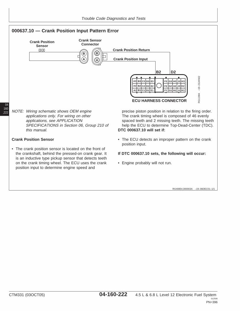
Trouble Code Diagnostics and Tests
04160,222
RG40854,000003A –19–06DEC01–1/1
000637.10 — Crank Position Input Pattern Error
Crank Position Input
Crank Position Return
Crank PositionSensor
Crank SensorConnector
A
B
A
B
B2 D2
A1
A2
A3 B3 C3 D3 E3
B2 C2 D2 E2
B1 C1 D1 E1 F1
F2
F3 G3 H3 J3 K3
G2 H2 J2 K2
G1 H1 J1 K1
ECU HARNESS CONNECTOR RG
1198
4–1
9–23
JAN
02
NOTE: Wiring schematic shows OEM engineapplications only. For wiring on otherapplications, see APPLICATIONSPECIFICATIONS in Section 06, Group 210 ofthis manual.
Crank Position Sensor
• The crank position sensor is located on the front ofthe crankshaft, behind the pressed-on crank gear. Itis an inductive type pickup sensor that detects teethon the crank timing wheel. The ECU uses the crankposition input to determine engine speed and
precise piston position in relation to the firing order.The crank timing wheel is composed of 46 evenlyspaced teeth and 2 missing teeth. The missing teethhelp the ECU to determine Top-Dead-Center (TDC).
DTC 000637.10 will set if:
• The ECU detects an improper pattern on the crankposition input.
If DTC 000637.10 sets, the following will occur:
• Engine probably will not run.
CTM331 (03OCT05) 04-160-222 4.5 L & 6.8 L Level 12 Electronic Fuel System012506
PN=396

Trouble Code Diagnostics and Tests
RG40854,000010A –19–23SEP05–1/1
000637.10 — Crank Position Input Pattern Error
The ECU detects an improper pattern on the crankposition input.
04160,223
– – –1/1
000637.10 Crank Position Input Pattern Error Diagnostic Procedure
– – –1/1
1 Connection Check IMPORTANT: Do not force probes into connector terminals or damage will result.Use JT07328 Connector Adapter Test Kit to make measurements in connectors.This will ensure that terminal damage does not occur.
NOTE: For wiring and theory of operation information, see DTC 000637.10 CRANKPOSITION INPUT PATTERN ERROR supporting information.
Perform a preliminary inspection of the ECU connector, the crank position sensorconnector, and any other connector. Look for dirty, damaged, or poorly positionedterminals.
No faulty connection(s):GO TO 2
Faulty connection(s):Repair faultyconnection(s)
– – –1/1
2 Intermittent Fault Test NOTE: For wiring and theory of operation information, see DTC 000637.10 CRANKPOSITION INPUT PATTERN ERROR supporting information.
1. Connect to the DST or SERVICE ADVISOR.
2. Ignition ON, engine OFF
3. Start the ECU communication software
4. Read DTCs using the DST orSERVICE ADVISOR.
5. Make note of any DTCs, then clear all DTCs
6. Ignition ON, engine running
7. Read DTCs using the DST orSERVICE ADVISOR.
000637.10 reoccurs:GO TO 3
000637.10 does notreoccur:Problem is intermittent. Ifno other codes arepresent, seeINTERMITTENT FAULTDIAGNOSTICS, earlier inthis Group.
SERVICE ADVISOR is a trademark of Deere & Company
CTM331 (03OCT05) 04-160-223 4.5 L & 6.8 L Level 12 Electronic Fuel System012506
PN=397
Trouble Code Diagnostics and Tests
– – –1/1
3 Crank PositionSensor Test
NOTE: For wiring and theory of operation information, see DTC 000637.10 CRANKPOSITION INPUT PATTERN ERROR supporting information.
1. Ignition OFF
2. Disconnect crank position sensor connector
3. Using a multimeter, measure resistance between both terminals of the crankposition sensor.
Between 2500 and 3500ohms:GO TO 4
Below 2500 ohms orabove 3500 ohms:Faulty crank positionsensor
04160,224
– – –1/1
4 Open in Crank SensorInput and ReturnCheck
NOTE: For wiring and theory of operation information, see DTC 000637.10 CRANKPOSITION INPUT PATTERN ERROR supporting information.
1. Ignition OFF
2. Disconnect crank position sensor connector
3. Disconnect ECU connector
4. Using a multimeter, measure resistance between:
• Terminal A of the crank position sensor harness connector and terminal B2 in theharness end of the ECU connector
• Terminal B of the crank position sensor harness connector and terminal D2 in theharness end of the ECU connector
Both measurements 5ohms or less:GO TO 5
Either measurementgreater than 5 ohms:Open in crank positionsensor input wireOROpen in crank positionsensor return wireORTerminals A and B in thecrank position sensorharness connectorpossibly inverted
– – –1/1
5 Crank Sensor InputWiring Check
NOTE: For wiring and theory of operation information, see DTC 000637.10 CRANKPOSITION INPUT PATTERN ERROR supporting information.
1. Ignition OFF
2. Crank position sensor connector and ECU connector still disconnected
3. Using a multimeter measure resistance between terminal B2 in the harness end ofthe ECU connector and the following:
• A good ground• All other terminals in both ECU connectors
All measurementsgreater than 2000 ohms:GO TO 6
Any measurement lessthan 2000 ohms:Faulty crank positionsensor input wiringharness
CTM331 (03OCT05) 04-160-224 4.5 L & 6.8 L Level 12 Electronic Fuel System012506
PN=398
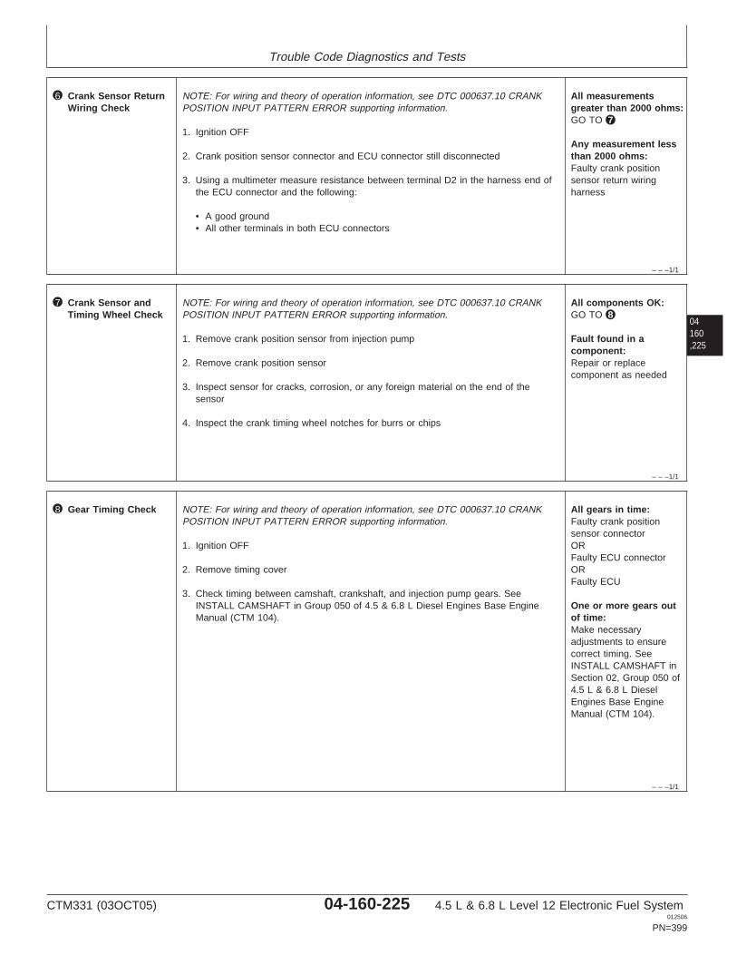
Trouble Code Diagnostics and Tests
– – –1/1
6 Crank Sensor ReturnWiring Check
NOTE: For wiring and theory of operation information, see DTC 000637.10 CRANKPOSITION INPUT PATTERN ERROR supporting information.
1. Ignition OFF
2. Crank position sensor connector and ECU connector still disconnected
3. Using a multimeter measure resistance between terminal D2 in the harness end ofthe ECU connector and the following:
• A good ground• All other terminals in both ECU connectors
All measurementsgreater than 2000 ohms:GO TO 7
Any measurement lessthan 2000 ohms:Faulty crank positionsensor return wiringharness
04160,225
– – –1/1
7 Crank Sensor andTiming Wheel Check
NOTE: For wiring and theory of operation information, see DTC 000637.10 CRANKPOSITION INPUT PATTERN ERROR supporting information.
1. Remove crank position sensor from injection pump
2. Remove crank position sensor
3. Inspect sensor for cracks, corrosion, or any foreign material on the end of thesensor
4. Inspect the crank timing wheel notches for burrs or chips
All components OK:GO TO 8
Fault found in acomponent:Repair or replacecomponent as needed
– – –1/1
8 Gear Timing Check NOTE: For wiring and theory of operation information, see DTC 000637.10 CRANKPOSITION INPUT PATTERN ERROR supporting information.
1. Ignition OFF
2. Remove timing cover
3. Check timing between camshaft, crankshaft, and injection pump gears. SeeINSTALL CAMSHAFT in Group 050 of 4.5 & 6.8 L Diesel Engines Base EngineManual (CTM 104).
All gears in time:Faulty crank positionsensor connectorORFaulty ECU connectorORFaulty ECU
One or more gears outof time:Make necessaryadjustments to ensurecorrect timing. SeeINSTALL CAMSHAFT inSection 02, Group 050 of4.5 L & 6.8 L DieselEngines Base EngineManual (CTM 104).
CTM331 (03OCT05) 04-160-225 4.5 L & 6.8 L Level 12 Electronic Fuel System012506
PN=399
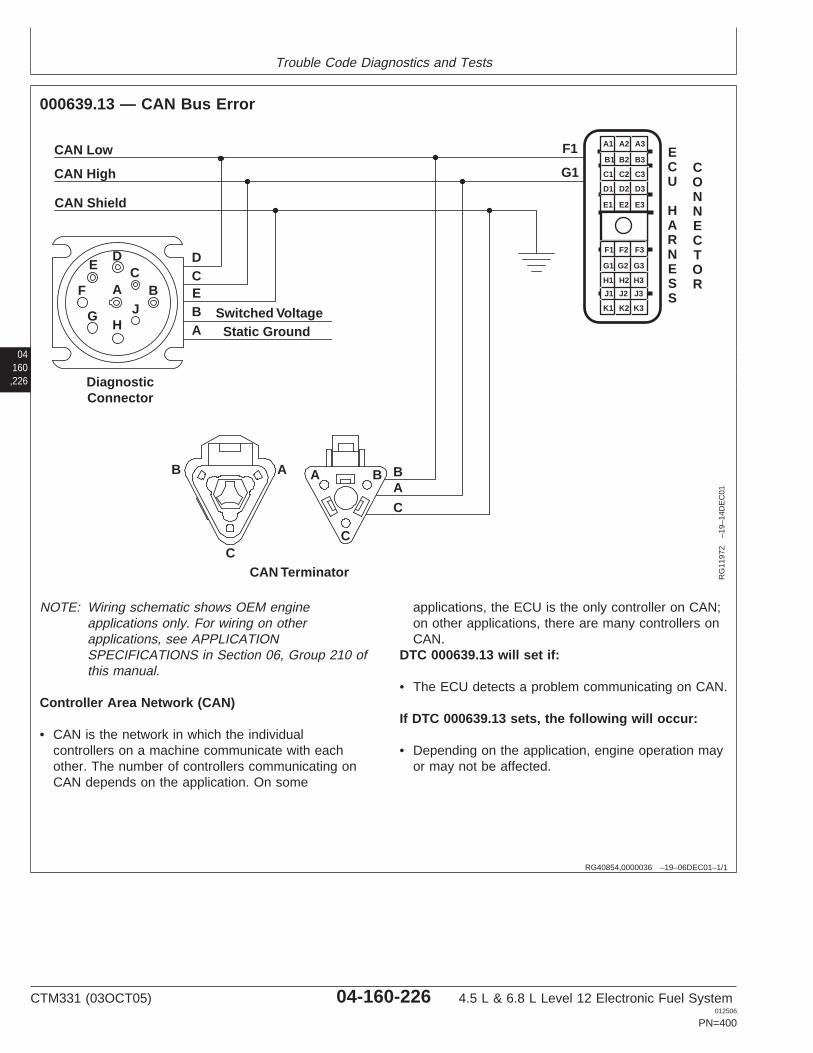
Trouble Code Diagnostics and Tests
04160,226
RG40854,0000036 –19–06DEC01–1/1
000639.13 — CAN Bus Error
CAN Low
CAN High
CAN Shield
BA
C
DCEBA
Switched Voltage
CAN Terminator
Static Ground
DiagnosticConnector
DC
BJ
HG
F
E
B A A B
CC
A
F1
G1
A1 A2 A3
B3
C3
D3
E3
B2
C2
D2
E2
B1
C1
D1
E1
F1 F2 F3
G3
H3
J3
K3
G2
H2
J2
K2
G1
H1
J1
K1
ECU
HARNESS
CONNECTOR
RG
1197
2–1
9–14
DE
C01
NOTE: Wiring schematic shows OEM engineapplications only. For wiring on otherapplications, see APPLICATIONSPECIFICATIONS in Section 06, Group 210 ofthis manual.
Controller Area Network (CAN)
• CAN is the network in which the individualcontrollers on a machine communicate with eachother. The number of controllers communicating onCAN depends on the application. On some
applications, the ECU is the only controller on CAN;on other applications, there are many controllers onCAN.
DTC 000639.13 will set if:
• The ECU detects a problem communicating on CAN.
If DTC 000639.13 sets, the following will occur:
• Depending on the application, engine operation mayor may not be affected.
CTM331 (03OCT05) 04-160-226 4.5 L & 6.8 L Level 12 Electronic Fuel System012506
PN=400
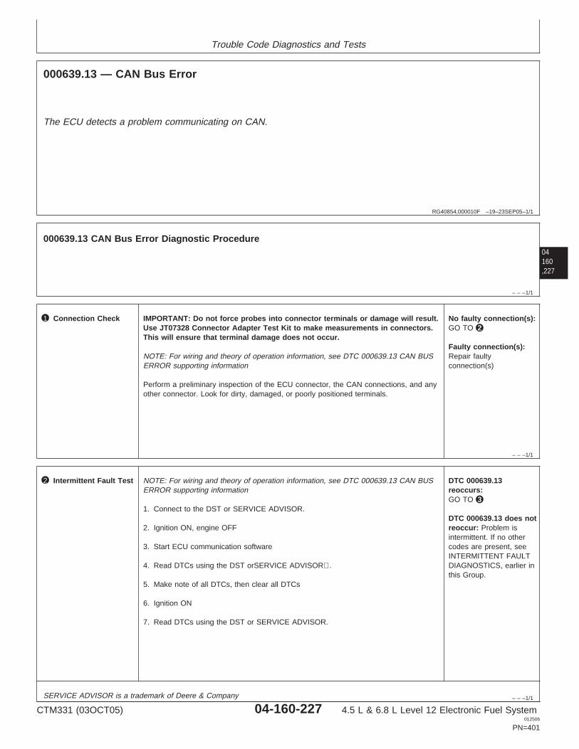
Trouble Code Diagnostics and Tests
RG40854,000010F –19–23SEP05–1/1
000639.13 — CAN Bus Error
The ECU detects a problem communicating on CAN.
04160,227
– – –1/1
000639.13 CAN Bus Error Diagnostic Procedure
– – –1/1
1 Connection Check IMPORTANT: Do not force probes into connector terminals or damage will result.Use JT07328 Connector Adapter Test Kit to make measurements in connectors.This will ensure that terminal damage does not occur.
NOTE: For wiring and theory of operation information, see DTC 000639.13 CAN BUSERROR supporting information
Perform a preliminary inspection of the ECU connector, the CAN connections, and anyother connector. Look for dirty, damaged, or poorly positioned terminals.
No faulty connection(s):GO TO 2
Faulty connection(s):Repair faultyconnection(s)
– – –1/1
2 Intermittent Fault Test NOTE: For wiring and theory of operation information, see DTC 000639.13 CAN BUSERROR supporting information
1. Connect to the DST or SERVICE ADVISOR.
2. Ignition ON, engine OFF
3. Start ECU communication software
4. Read DTCs using the DST orSERVICE ADVISOR.
5. Make note of all DTCs, then clear all DTCs
6. Ignition ON
7. Read DTCs using the DST or SERVICE ADVISOR.
DTC 000639.13reoccurs:GO TO 3
DTC 000639.13 does notreoccur: Problem isintermittent. If no othercodes are present, seeINTERMITTENT FAULTDIAGNOSTICS, earlier inthis Group.
SERVICE ADVISOR is a trademark of Deere & Company
CTM331 (03OCT05) 04-160-227 4.5 L & 6.8 L Level 12 Electronic Fuel System012506
PN=401
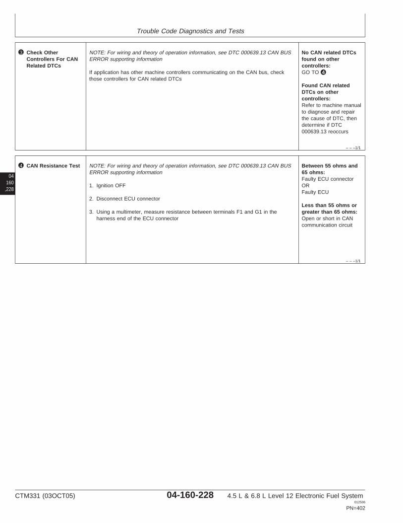
Trouble Code Diagnostics and Tests
– – –1/1
3 Check OtherControllers For CANRelated DTCs
NOTE: For wiring and theory of operation information, see DTC 000639.13 CAN BUSERROR supporting information
If application has other machine controllers communicating on the CAN bus, checkthose controllers for CAN related DTCs
No CAN related DTCsfound on othercontrollers:GO TO 4
Found CAN relatedDTCs on othercontrollers:Refer to machine manualto diagnose and repairthe cause of DTC, thendetermine if DTC000639.13 reoccurs
04160,228
– – –1/1
4 CAN Resistance Test NOTE: For wiring and theory of operation information, see DTC 000639.13 CAN BUSERROR supporting information
1. Ignition OFF
2. Disconnect ECU connector
3. Using a multimeter, measure resistance between terminals F1 and G1 in theharness end of the ECU connector
Between 55 ohms and65 ohms:Faulty ECU connectorORFaulty ECU
Less than 55 ohms orgreater than 65 ohms:Open or short in CANcommunication circuit
CTM331 (03OCT05) 04-160-228 4.5 L & 6.8 L Level 12 Electronic Fuel System012506
PN=402
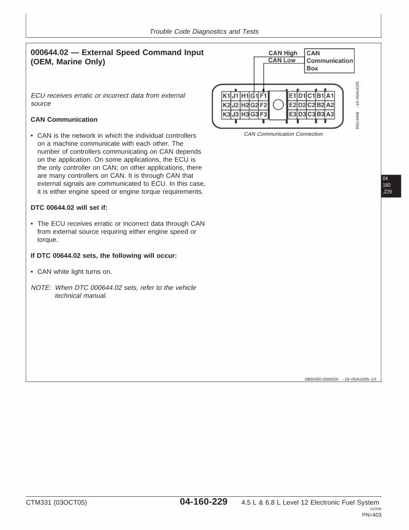
Trouble Code Diagnostics and Tests
04160,229
DB92450,000002A –19–05AUG05–1/1
000644.02 — External Speed Command Input(OEM, Marine Only)
RG
1444
8–1
9–05
AU
G05
CAN Communication Connection
ECU receives erratic or incorrect data from externalsource
CAN Communication
• CAN is the network in which the individual controllerson a machine communicate with each other. Thenumber of controllers communicating on CAN dependson the application. On some applications, the ECU isthe only controller on CAN; on other applications, thereare many controllers on CAN. It is through CAN thatexternal signals are communicated to ECU. In this case,it is either engine speed or engine torque requirements.
DTC 00644.02 will set if:
• The ECU receives erratic or incorrect data through CANfrom external source requiring either engine speed ortorque.
If DTC 00644.02 sets, the following will occur:
• CAN white light turns on.
NOTE: When DTC 000644.02 sets, refer to the vehicletechnical manual.
CTM331 (03OCT05) 04-160-229 4.5 L & 6.8 L Level 12 Electronic Fuel System012506
PN=403
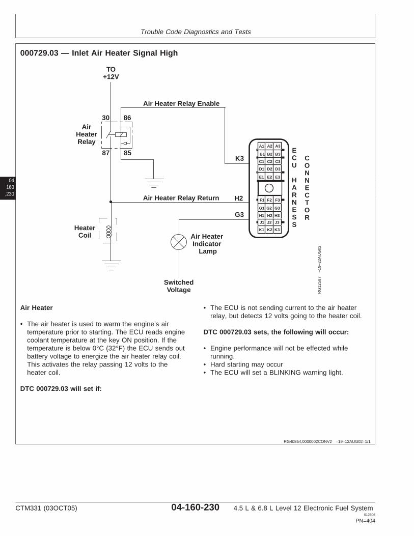
Trouble Code Diagnostics and Tests
04160,230
RG40854,0000002CONV2 –19–12AUG02–1/1
000729.03 — Inlet Air Heater Signal High
K3
H2
AirHeaterRelay
8587
30 86
TO+12V
Air Heater Relay Enable
Air Heater Relay Return
Air HeaterIndicator
Lamp
SwitchedVoltage
HeaterCoil
G3
A1 A2 A3
B3
C3
D3
E3
B2
C2
D2
E2
B1
C1
D1
E1
F1 F2 F3
G3
H3
J3
K3
G2
H2
J2
K2
G1
H1
J1
K1
ECU
HARNESS
CONNECTOR
RG
1258
7–1
9–22
AU
G02
Air Heater
• The air heater is used to warm the engine’s airtemperature prior to starting. The ECU reads enginecoolant temperature at the key ON position. If thetemperature is below 0°C (32°F) the ECU sends outbattery voltage to energize the air heater relay coil.This activates the relay passing 12 volts to theheater coil.
DTC 000729.03 will set if:
• The ECU is not sending current to the air heaterrelay, but detects 12 volts going to the heater coil.
DTC 000729.03 sets, the following will occur:
• Engine performance will not be effected whilerunning.
• Hard starting may occur• The ECU will set a BLINKING warning light.
CTM331 (03OCT05) 04-160-230 4.5 L & 6.8 L Level 12 Electronic Fuel System012506
PN=404
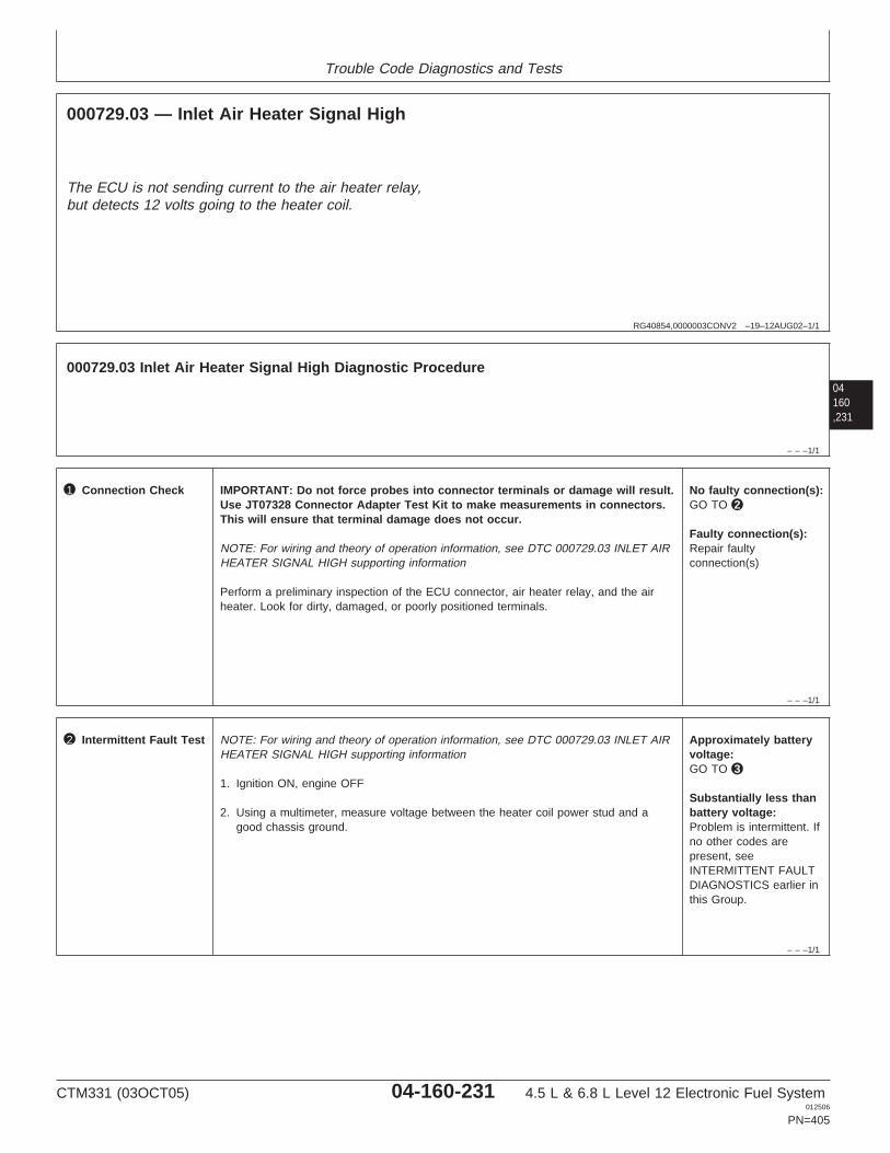
Trouble Code Diagnostics and Tests
RG40854,0000003CONV2 –19–12AUG02–1/1
000729.03 — Inlet Air Heater Signal High
The ECU is not sending current to the air heater relay,but detects 12 volts going to the heater coil.
04160,231
– – –1/1
000729.03 Inlet Air Heater Signal High Diagnostic Procedure
– – –1/1
1 Connection Check IMPORTANT: Do not force probes into connector terminals or damage will result.Use JT07328 Connector Adapter Test Kit to make measurements in connectors.This will ensure that terminal damage does not occur.
NOTE: For wiring and theory of operation information, see DTC 000729.03 INLET AIRHEATER SIGNAL HIGH supporting information
Perform a preliminary inspection of the ECU connector, air heater relay, and the airheater. Look for dirty, damaged, or poorly positioned terminals.
No faulty connection(s):GO TO 2
Faulty connection(s):Repair faultyconnection(s)
– – –1/1
2 Intermittent Fault Test NOTE: For wiring and theory of operation information, see DTC 000729.03 INLET AIRHEATER SIGNAL HIGH supporting information
1. Ignition ON, engine OFF
2. Using a multimeter, measure voltage between the heater coil power stud and agood chassis ground.
Approximately batteryvoltage:GO TO 3
Substantially less thanbattery voltage:Problem is intermittent. Ifno other codes arepresent, seeINTERMITTENT FAULTDIAGNOSTICS earlier inthis Group.
CTM331 (03OCT05) 04-160-231 4.5 L & 6.8 L Level 12 Electronic Fuel System012506
PN=405
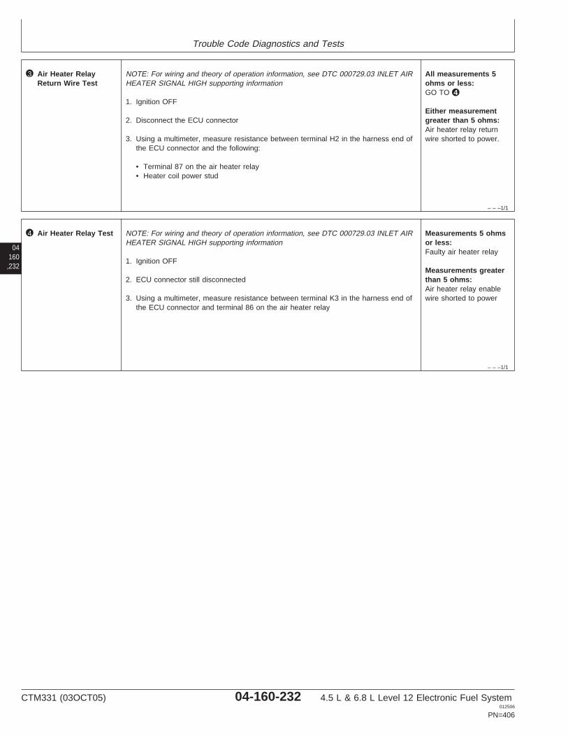
Trouble Code Diagnostics and Tests
– – –1/1
3 Air Heater RelayReturn Wire Test
NOTE: For wiring and theory of operation information, see DTC 000729.03 INLET AIRHEATER SIGNAL HIGH supporting information
1. Ignition OFF
2. Disconnect the ECU connector
3. Using a multimeter, measure resistance between terminal H2 in the harness end ofthe ECU connector and the following:
• Terminal 87 on the air heater relay• Heater coil power stud
All measurements 5ohms or less:GO TO 4
Either measurementgreater than 5 ohms:Air heater relay returnwire shorted to power.
04160,232
– – –1/1
4 Air Heater Relay Test NOTE: For wiring and theory of operation information, see DTC 000729.03 INLET AIRHEATER SIGNAL HIGH supporting information
1. Ignition OFF
2. ECU connector still disconnected
3. Using a multimeter, measure resistance between terminal K3 in the harness end ofthe ECU connector and terminal 86 on the air heater relay
Measurements 5 ohmsor less:Faulty air heater relay
Measurements greaterthan 5 ohms:Air heater relay enablewire shorted to power
CTM331 (03OCT05) 04-160-232 4.5 L & 6.8 L Level 12 Electronic Fuel System012506
PN=406

Trouble Code Diagnostics and Tests
04160,233
CTM331 (03OCT05) 04-160-233 4.5 L & 6.8 L Level 12 Electronic Fuel System012506
PN=407
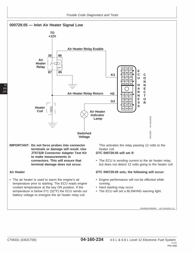
Trouble Code Diagnostics and Tests
04160,234
RG40854,0000004 –19–12AUG02–1/1
000729.05 — Inlet Air Heater Signal Low
K3
H2
AirHeaterRelay
8587
30 86
TO+12V
Air Heater Relay Enable
Air Heater Relay Return
Air HeaterIndicator
Lamp
SwitchedVoltage
HeaterCoil
G3
A1 A2 A3
B3
C3
D3
E3
B2
C2
D2
E2
B1
C1
D1
E1
F1 F2 F3
G3
H3
J3
K3
G2
H2
J2
K2
G1
H1
J1
K1
ECU
HARNESS
CONNECTOR
RG
1258
7–1
9–22
AU
G02
IMPORTANT: Do not force probes into connectorterminals or damage will result. UseJT07328 Connector Adapter Test Kitto make measurements inconnectors. This will ensure thatterminal damage does not occur.
Air Heater
• The air heater is used to warm the engine’s airtemperature prior to starting. The ECU reads enginecoolant temperature at the key ON position. If thetemperature is below 0°C (32°F) the ECU sends outbattery voltage to energize the air heater relay coil.
This activates the relay passing 12 volts to theheater coil.
DTC 000729.05 will set if:
• The ECU is sending current to the air heater relay,but does not detect 12 volts going to the heater coil.
DTC 000729.05 sets, the following will occur:
• Engine performance will not be effected whilerunning.
• Hard starting may occur• The ECU will set a BLINKING warning light.
CTM331 (03OCT05) 04-160-234 4.5 L & 6.8 L Level 12 Electronic Fuel System012506
PN=408
Trouble Code Diagnostics and Tests
RG40854,0000005 –19–23SEP05–1/1
000729.05 — Inlet Air Heater Signal Low
The ECU is sending current to the air heater relay, butdoes not detect 12 volts going to the heater coil.
04160,235
– – –1/1
000729.05 Inlet Air Heater Signal Low Diagnostic Procedure
– – –1/1
1 Connection Check IMPORTANT: Do not force probes into connector terminals or damage will result.Use JT07328 Connector Adapter Test Kit to make measurements in connectors.This will ensure that terminal damage does not occur.
NOTE: For wiring and theory of operation information, see DTC 000729.05 INLET AIRHEATER SIGNAL LOW supporting information
Perform a preliminary inspection of the ECU connector, air heater relay, and the airheater. Look for dirty, damaged, or poorly positioned terminals.
No faulty connection(s):GO TO 2
Faulty connection(s):Repair faultyconnection(s)
– – –1/1
2 Intermittent Fault Test NOTE: For wiring and theory of operation information, see DTC 000729.05 INLET AIRHEATER SIGNAL LOW supporting information
1. Connect to the DST or SERVICE ADVISOR.
2. Ignition ON, engine OFF
3. Start the ECU communication software
4. Make note of any DTCs, then clear all DTCs
5. Ignition ON, engine running
6. Read DTCs using the DST orSERVICE ADVISOR.
000729.05 reoccurs:GO TO 3
000729.05 doesn’treoccur:Problem is intermittent. Ifno other codes arepresent, seeINTERMITTENT FAULTDIAGNOSTICS earlier inthis Group.
SERVICE ADVISOR is a trademark of Deere & Company
CTM331 (03OCT05) 04-160-235 4.5 L & 6.8 L Level 12 Electronic Fuel System012506
PN=409
Trouble Code Diagnostics and Tests
– – –1/1
3 Air Heater Relay Test NOTE: For wiring and theory of operation information, see DTC 000729.05 INLET AIRHEATER SIGNAL LOW supporting information
1. Cycle ignition from OFF to ON
2. Listen to air heater relay
Relay clicks:GO TO 4
Relay doesn’t click:Open in air heater relayenable wireOROpen in air heater relaygroundORFaulty Relay
04160,236
– – –1/1
4 Air Heater RelayVoltage Test
NOTE: For wiring and theory of operation information, see DTC 000729.05 INLET AIRHEATER SIGNAL LOW supporting information
1. Ignition ON, engine OFF
2. Using a multimeter, measure voltage between terminal 30 on the air heater relayand a good chassis ground
Approximately batteryvoltage:GO TO 5
Substantially less thanbattery voltage:Open in battery voltagesupply wireORShort to ground in batteryvoltage supply wire
– – –1/1
5 Heater Coil PowerTest
NOTE: For wiring and theory of operation information, see DTC 000729.05 INLET AIRHEATER SIGNAL LOW supporting information
1. Ignition ON, engine OFF
2. Using a multimeter, measure voltage between the heater coil power stud and agood chassis ground
Approximately batteryvoltage:Open in air heater relayreturn wire
Substantially less thanbattery voltage:Open in wire between airheater relay terminal 87and the heater coilORShort to ground in wirebetween air heater relayterminal 87 and theheater coil
CTM331 (03OCT05) 04-160-236 4.5 L & 6.8 L Level 12 Electronic Fuel System012506
PN=410
Trouble Code Diagnostics and Tests
04160,237
RG40854,0000114 –19–23SEP05–1/1
000898.09 — Vehicle Speed or Torque Message Invalid
The ECU does not receive the engine speed or torquemessage over CAN or it is not valid.
CAN (Controller Area Network) Vehicle Speed orTorque Message
• The CAN (Controller Area Network) transmits thevehicle’s desired engine speed or torque to the ECUfrom another controller.
DTC 000898.09 will set if:
• The ECU does not receive the engine speed ortorque message over CAN or it is not valid.
If DTC 000898.09 sets, the following will occur:
• The ECU will default engine speed to low idle.
If DTC 000898.09 sets:
• Connect to the DST or SERVICE ADVISOR.• With ignition ON and engine OFF, start the ECU
communication software• Read active DTCs and stored DTCs using the DST
orSERVICE ADVISOR. If DTC 000639.13 alsooccurs, see DTC 000639.13 CAN BUS ERRORDIAGNOSTIC PROCEDURE earlier in this Group.
• If no other stored or active CAN or vehicle relatedDTCs are found, replace the ECU and retest.
SERVICE ADVISOR is a trademark of Deere & Company
CTM331 (03OCT05) 04-160-237 4.5 L & 6.8 L Level 12 Electronic Fuel System012506
PN=411
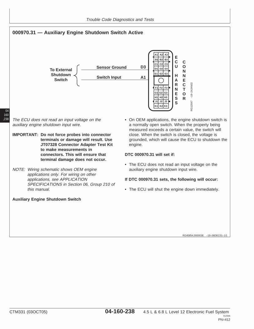
Trouble Code Diagnostics and Tests
04160,238
RG40854,000003E –19–06DEC01–1/1
000970.31 — Auxiliary Engine Shutdown Switch Active
To ExternalShutdown
Switch Switch Input A1
D3
A1 A2 A3
B3
C3
D3
E3
B2
C2
D2
E2
B1
C1
D1
E1
F1 F2 F3
G3
H3
J3
K3
G2
H2
J2
K2
G1
H1
J1
K1
ECU
HARNESS
CONNECTOR
Sensor Ground
RG
1204
7–1
9–24
JAN
02
The ECU does not read an input voltage on theauxiliary engine shutdown input wire.
IMPORTANT: Do not force probes into connectorterminals or damage will result. UseJT07328 Connector Adapter Test Kitto make measurements inconnectors. This will ensure thatterminal damage does not occur.
NOTE: Wiring schematic shows OEM engineapplications only. For wiring on otherapplications, see APPLICATIONSPECIFICATIONS in Section 06, Group 210 ofthis manual.
Auxiliary Engine Shutdown Switch
• On OEM applications, the engine shutdown switch isa normally open switch. When the property beingmeasured exceeds a certain value, the switch willclose. When the switch is closed, the voltage isgrounded, which will cause the ECU to shutdown theengine.
DTC 000970.31 will set if:
• The ECU does not read an input voltage on theauxiliary engine shutdown input wire.
If DTC 000970.31 sets, the following will occur:
• The ECU will shut the engine down immediately.
CTM331 (03OCT05) 04-160-238 4.5 L & 6.8 L Level 12 Electronic Fuel System012506
PN=412
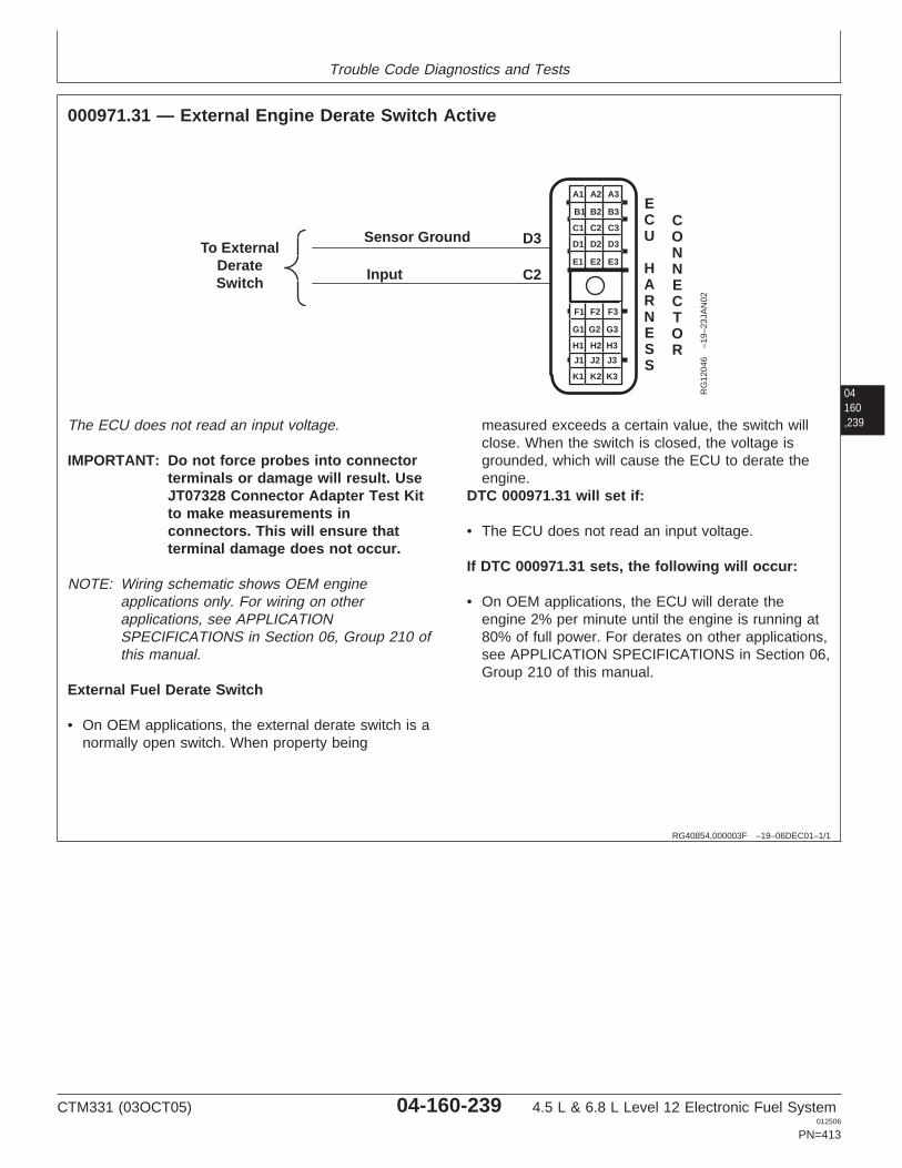
Trouble Code Diagnostics and Tests
04160,239
RG40854,000003F –19–06DEC01–1/1
000971.31 — External Engine Derate Switch Active
To ExternalDerateSwitch Input C2
D3
A1 A2 A3
B3
C3
D3
E3
B2
C2
D2
E2
B1
C1
D1
E1
F1 F2 F3
G3
H3
J3
K3
G2
H2
J2
K2
G1
H1
J1
K1
ECU
HARNESS
CONNECTOR
Sensor Ground
RG
1204
6–1
9–23
JAN
02
The ECU does not read an input voltage.
IMPORTANT: Do not force probes into connectorterminals or damage will result. UseJT07328 Connector Adapter Test Kitto make measurements inconnectors. This will ensure thatterminal damage does not occur.
NOTE: Wiring schematic shows OEM engineapplications only. For wiring on otherapplications, see APPLICATIONSPECIFICATIONS in Section 06, Group 210 ofthis manual.
External Fuel Derate Switch
• On OEM applications, the external derate switch is anormally open switch. When property being
measured exceeds a certain value, the switch willclose. When the switch is closed, the voltage isgrounded, which will cause the ECU to derate theengine.
DTC 000971.31 will set if:
• The ECU does not read an input voltage.
If DTC 000971.31 sets, the following will occur:
• On OEM applications, the ECU will derate theengine 2% per minute until the engine is running at80% of full power. For derates on other applications,see APPLICATION SPECIFICATIONS in Section 06,Group 210 of this manual.
CTM331 (03OCT05) 04-160-239 4.5 L & 6.8 L Level 12 Electronic Fuel System012506
PN=413
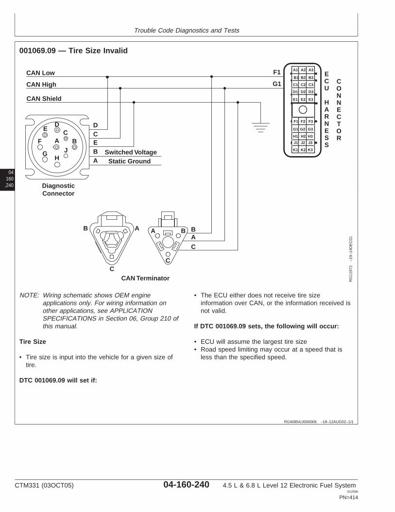
Trouble Code Diagnostics and Tests
04160,240
RG40854,0000006 –19–12AUG02–1/1
001069.09 — Tire Size Invalid
CAN Low
CAN High
CAN Shield
BA
C
DCEBA
Switched Voltage
CAN Terminator
Static Ground
DiagnosticConnector
DC
BJ
HG
F
E
B A A B
CC
A
F1
G1
A1 A2 A3
B3
C3
D3
E3
B2
C2
D2
E2
B1
C1
D1
E1
F1 F2 F3
G3
H3
J3
K3
G2
H2
J2
K2
G1
H1
J1
K1
ECU
HARNESS
CONNECTOR
RG
1197
2–1
9–14
DE
C01
NOTE: Wiring schematic shows OEM engineapplications only. For wiring information onother applications, see APPLICATIONSPECIFICATIONS in Section 06, Group 210 ofthis manual.
Tire Size
• Tire size is input into the vehicle for a given size oftire.
DTC 001069.09 will set if:
• The ECU either does not receive tire sizeinformation over CAN, or the information received isnot valid.
If DTC 001069.09 sets, the following will occur:
• ECU will assume the largest tire size• Road speed limiting may occur at a speed that is
less than the specified speed.
CTM331 (03OCT05) 04-160-240 4.5 L & 6.8 L Level 12 Electronic Fuel System012506
PN=414
Trouble Code Diagnostics and Tests
RG40854,0000007 –19–23SEP05–1/1
001069.09 — Tire Size Invalid
The ECU either does not receive tire size informationover CAN, or the information received is not valid.
04160,241
– – –1/1
001069.09 Tire Size Invalid Diagnostic Procedure
– – –1/1
1 Connection Check IMPORTANT: Do not force probes into connector terminals or damage will result.Use JT07328 Connector Adapter Test Kit to make measurements in connectors.This will ensure that terminal damage does not occur.
NOTE: For wiring and theory of operation, see DTC 001069.09 TIRE SIZE INVALIDsupporting information.
Perform a preliminary inspection of ECU connectors looking for dirty, damaged, orpoorly positioned terminals.
No faulty connections:GO TO 2
Faulty connections:Repair faultyconnection(s).
– – –1/1
2 Intermittent Fault Test NOTE: For wiring and theory of operation, see DTC 001069.09 TIRE SIZE INVALIDsupporting information.
1. Connect to the DST or SERVICE ADVISOR.
2. Ignition ON, engine OFF
3. Start the ECU diagnostic software
4. Make note of any DTCs, then clear all DTCs.
5. Ignition ON, engine running
6. Read DTCs using the DST orSERVICE ADVISOR.
001069.09 reoccurs:GO TO 3
001069.09 does notreoccur:Problem is intermittent. Ifno other codes arepresent, seeINTERMITTENT FAULTDIAGNOSTICS earlier inthis Group.
SERVICE ADVISOR is a trademark of Deere & Company
CTM331 (03OCT05) 04-160-241 4.5 L & 6.8 L Level 12 Electronic Fuel System012506
PN=415
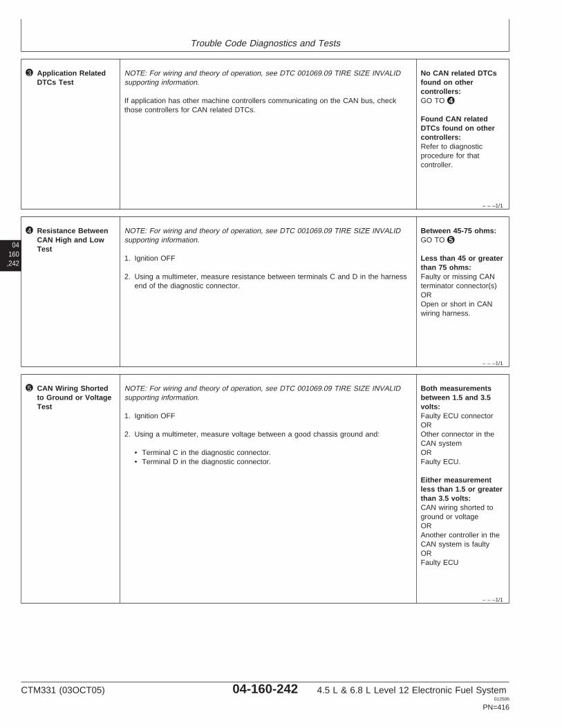
Trouble Code Diagnostics and Tests
– – –1/1
3 Application RelatedDTCs Test
NOTE: For wiring and theory of operation, see DTC 001069.09 TIRE SIZE INVALIDsupporting information.
If application has other machine controllers communicating on the CAN bus, checkthose controllers for CAN related DTCs.
No CAN related DTCsfound on othercontrollers:GO TO 4
Found CAN relatedDTCs found on othercontrollers:Refer to diagnosticprocedure for thatcontroller.
04160,242
– – –1/1
4 Resistance BetweenCAN High and LowTest
NOTE: For wiring and theory of operation, see DTC 001069.09 TIRE SIZE INVALIDsupporting information.
1. Ignition OFF
2. Using a multimeter, measure resistance between terminals C and D in the harnessend of the diagnostic connector.
Between 45-75 ohms:GO TO 5
Less than 45 or greaterthan 75 ohms:Faulty or missing CANterminator connector(s)OROpen or short in CANwiring harness.
– – –1/1
5 CAN Wiring Shortedto Ground or VoltageTest
NOTE: For wiring and theory of operation, see DTC 001069.09 TIRE SIZE INVALIDsupporting information.
1. Ignition OFF
2. Using a multimeter, measure voltage between a good chassis ground and:
• Terminal C in the diagnostic connector.• Terminal D in the diagnostic connector.
Both measurementsbetween 1.5 and 3.5volts:Faulty ECU connectorOROther connector in theCAN systemORFaulty ECU.
Either measurementless than 1.5 or greaterthan 3.5 volts:CAN wiring shorted toground or voltageORAnother controller in theCAN system is faultyORFaulty ECU
CTM331 (03OCT05) 04-160-242 4.5 L & 6.8 L Level 12 Electronic Fuel System012506
PN=416

Trouble Code Diagnostics and Tests
04160,243
CTM331 (03OCT05) 04-160-243 4.5 L & 6.8 L Level 12 Electronic Fuel System012506
PN=417
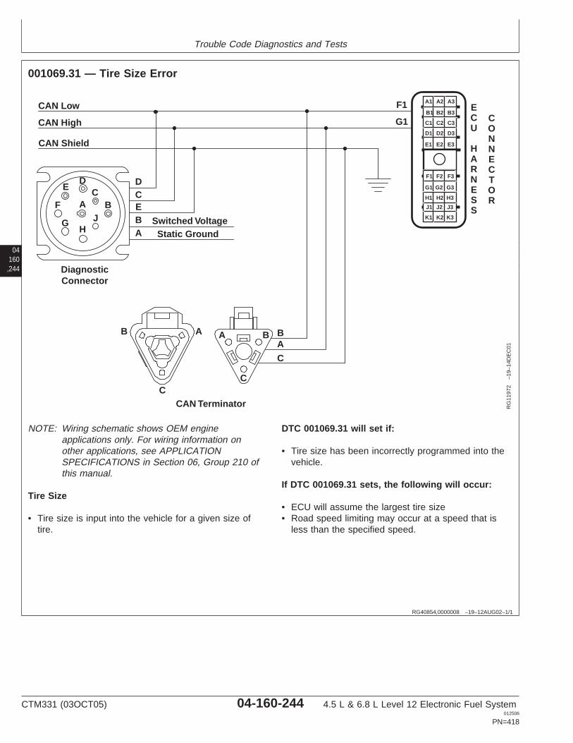
Trouble Code Diagnostics and Tests
04160,244
RG40854,0000008 –19–12AUG02–1/1
001069.31 — Tire Size Error
CAN Low
CAN High
CAN Shield
BA
C
DCEBA
Switched Voltage
CAN Terminator
Static Ground
DiagnosticConnector
DC
BJ
HG
F
E
B A A B
CC
A
F1
G1
A1 A2 A3
B3
C3
D3
E3
B2
C2
D2
E2
B1
C1
D1
E1
F1 F2 F3
G3
H3
J3
K3
G2
H2
J2
K2
G1
H1
J1
K1
ECU
HARNESS
CONNECTOR
RG
1197
2–1
9–14
DE
C01
NOTE: Wiring schematic shows OEM engineapplications only. For wiring information onother applications, see APPLICATIONSPECIFICATIONS in Section 06, Group 210 ofthis manual.
Tire Size
• Tire size is input into the vehicle for a given size oftire.
DTC 001069.31 will set if:
• Tire size has been incorrectly programmed into thevehicle.
If DTC 001069.31 sets, the following will occur:
• ECU will assume the largest tire size• Road speed limiting may occur at a speed that is
less than the specified speed.
CTM331 (03OCT05) 04-160-244 4.5 L & 6.8 L Level 12 Electronic Fuel System012506
PN=418
Trouble Code Diagnostics and Tests
RG40854,0000009 –19–23SEP05–1/1
001069.31 — Tire Size Error
Tire size has been incorrectly programmed into thevehicle.
04160,245
– – –1/1
001069.31 Tire Size Error Diagnostic Procedure
– – –1/1
1 Connection Check IMPORTANT: Do not force probes into connector terminals or damage will result.Use JT07328 Connector Adapter Test Kit to make measurements in connectors.This will ensure that terminal damage does not occur.
NOTE: For wiring and theory of operation information, see DTC 001069.31 TIRE SIZEERROR supporting information.
Perform a preliminary inspection of the ECU, BIF, and BCU connectors looking fordirty, damaged, or poorly positioned terminals.
No faulty connection(s):GO TO 2
Faulty connection(s):Repair faultyconnection(s).
– – –1/1
2 Intermittent Fault Test NOTE: For wiring and theory of operation information, see DTC 001069.31 TIRE SIZEERROR supporting information.
1. Connect to the DST or SERVICE ADVISOR.
2. Ignition ON, engine OFF
3. Start ECU communication software.
4. Read DTCs using the DST orSERVICE ADVISOR.
5. Clear all DTCs
6. Engine running, vehicle under normal operating conditions.
7. Read DTCs using the DST or SERVICE ADVISOR.
001069.31 reoccurs:Reprogram tire size onvehicle.
001069.31 does notreoccur: Problem isintermittent. If no othercodes are present, seeINTERMITTENT FAULTDIAGNOSTICS, earlier inthis Group.
SERVICE ADVISOR is a trademark of Deere & Company
CTM331 (03OCT05) 04-160-245 4.5 L & 6.8 L Level 12 Electronic Fuel System012506
PN=419
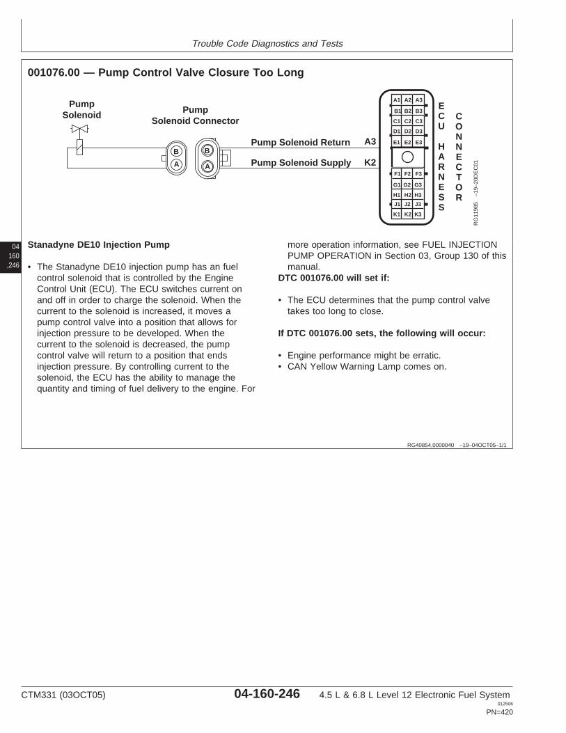
Trouble Code Diagnostics and Tests
04160,246
RG40854,0000040 –19–04OCT05–1/1
001076.00 — Pump Control Valve Closure Too Long
A1 A2 A3
B3
C3
D3
E3
B2
C2
D2
E2
B1
C1
D1
E1
F1 F2 F3
G3
H3
J3
K3
G2
H2
J2
K2
G1
H1
J1
K1
Pump Solenoid Return
Pump Solenoid Supply
PumpSolenoid Pump
Solenoid Connector
A3
K2
CONNECTOR
ECU
HARNESS
B
A
B
A
RG
1198
5–1
9–20
DE
C01
Stanadyne DE10 Injection Pump
• The Stanadyne DE10 injection pump has an fuelcontrol solenoid that is controlled by the EngineControl Unit (ECU). The ECU switches current onand off in order to charge the solenoid. When thecurrent to the solenoid is increased, it moves apump control valve into a position that allows forinjection pressure to be developed. When thecurrent to the solenoid is decreased, the pumpcontrol valve will return to a position that endsinjection pressure. By controlling current to thesolenoid, the ECU has the ability to manage thequantity and timing of fuel delivery to the engine. For
more operation information, see FUEL INJECTIONPUMP OPERATION in Section 03, Group 130 of thismanual.
DTC 001076.00 will set if:
• The ECU determines that the pump control valvetakes too long to close.
If DTC 001076.00 sets, the following will occur:
• Engine performance might be erratic.• CAN Yellow Warning Lamp comes on.
CTM331 (03OCT05) 04-160-246 4.5 L & 6.8 L Level 12 Electronic Fuel System012506
PN=420

Trouble Code Diagnostics and Tests
RG40854,0000124 –19–23SEP05–1/1
001076.00 — Pump Control Valve Closure Too Long
The ECU determines that the pump control valve takestoo long to close.
04160,247
– – –1/1
001076.00 Pump Control Valve Closure Too Long Diagnostic Procedure
– – –1/1
1 Connection Check IMPORTANT: Do not force probes into connector terminals or damage will result.Use JT07328 Connector Adapter Test Kit to make measurements in connectors.This will ensure that terminal damage does not occur.
NOTE: For wiring and theory of operation information, see DTC 001076.00 PUMPCONTROL VALVE CLOSURE TOO LONG supporting information.
Perform a preliminary inspection of the ECU connector, the pump connector, and anyother connector. Look for dirty, damaged, or poorly positioned terminals.
No faulty connection(s):GO TO 2
Faulty connection(s):Repair faultyconnection(s)
– – –1/1
2 Intermittent Fault Test NOTE: For wiring and theory of operation information, see DTC 001076.00 PUMPCONTROL VALVE CLOSURE TOO LONG supporting information.
1. Connect to the DST or SERVICE ADVISOR.
2. Ignition ON, engine OFF
3. Start the ECU communication software.
4. Make note of any DTCs, then clear all DTCs.
5. Ignition ON, engine cranking or running
6. Read DTCs using the DST orSERVICE ADVISOR.
001076.00 reoccurs:GO TO 3
001076.00 does notreoccur:Problem is intermittent. Ifno other codes arepresent, seeINTERMITTENT FAULTDIAGNOSTICS, earlier inthis Group.
SERVICE ADVISOR is a trademark of Deere & Company
CTM331 (03OCT05) 04-160-247 4.5 L & 6.8 L Level 12 Electronic Fuel System012506
PN=421

Trouble Code Diagnostics and Tests
– – –1/1
3 ECU Test NOTE: For wiring and theory of operation information, see DTC 001076.00 PUMPCONTROL VALVE CLOSURE TOO LONG supporting information.
Substitute existing ECU for Known Good One. Download Payload.
Problem Resolved:Replace original ECU.
Problem Not Resolved:Replace pump.
04160,248
CTM331 (03OCT05) 04-160-248 4.5 L & 6.8 L Level 12 Electronic Fuel System012506
PN=422

Trouble Code Diagnostics and Tests
04160,249
CTM331 (03OCT05) 04-160-249 4.5 L & 6.8 L Level 12 Electronic Fuel System012506
PN=423

Trouble Code Diagnostics and Tests
04160,250
RG40854,0000044 –19–06DEC01–1/1
001076.01 — Pump Control Valve Closure Too Short
A1 A2 A3
B3
C3
D3
E3
B2
C2
D2
E2
B1
C1
D1
E1
F1 F2 F3
G3
H3
J3
K3
G2
H2
J2
K2
G1
H1
J1
K1
Pump Solenoid Return
Pump Solenoid Supply
PumpSolenoid Pump
Solenoid Connector
A3
K2
CONNECTOR
ECU
HARNESS
B
A
B
A
RG
1198
5–1
9–20
DE
C01
Stanadyne DE10 Injection Pump
• The Stanadyne DE10 injection pump has an fuelcontrol solenoid that is controlled by the EngineControl Unit (ECU). The ECU switches current onand off in order to charge the solenoid. When thecurrent to the solenoid is increased, it moves apump control valve into a position that allows forinjection pressure to be developed. When thecurrent to the solenoid is decreased, the pumpcontrol valve will return to a position that endsinjection pressure. By controlling current to thesolenoid, the ECU has the ability to manage the
quantity and timing of fuel delivery to the engine. Formore operation information, see FUEL INJECTIONPUMP OPERATION in Section 03, Group 130 of thismanual.
DTC 001076.01 will set if:
• The ECU determines that the control valve closestoo quickly.
If DTC 001076.01 sets, the following will occur:
• Engine performance may be erratic.
CTM331 (03OCT05) 04-160-250 4.5 L & 6.8 L Level 12 Electronic Fuel System012506
PN=424
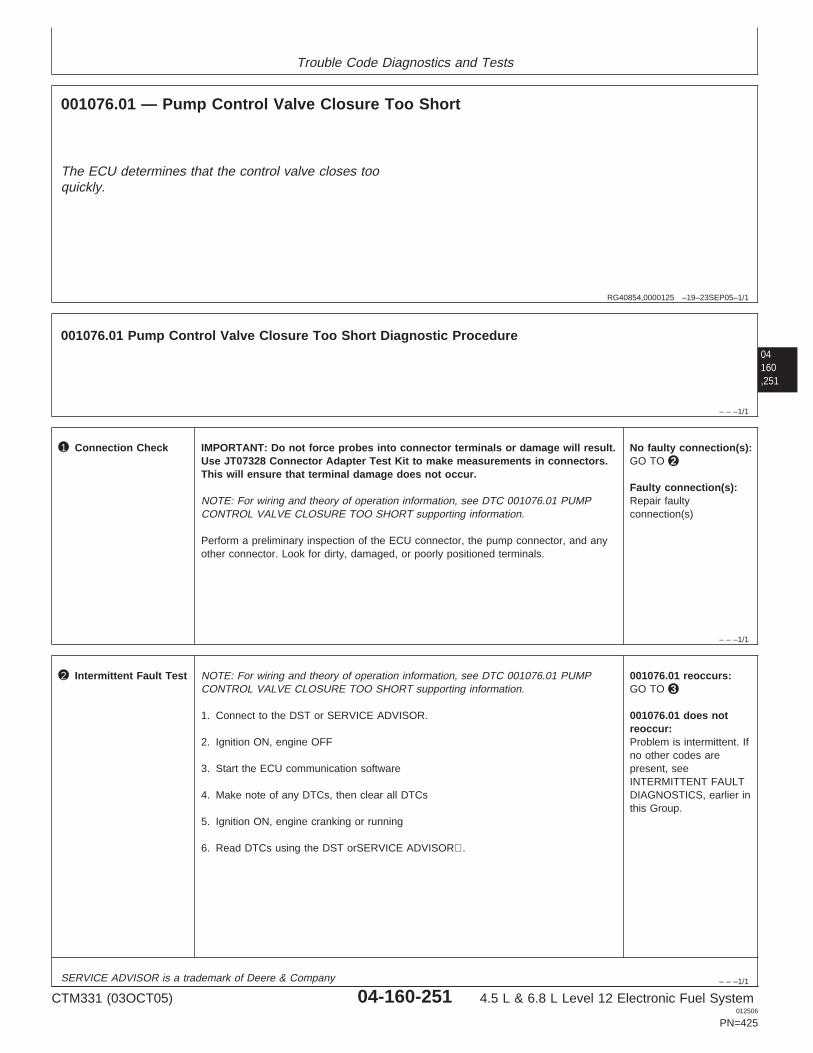
Trouble Code Diagnostics and Tests
RG40854,0000125 –19–23SEP05–1/1
001076.01 — Pump Control Valve Closure Too Short
The ECU determines that the control valve closes tooquickly.
04160,251
– – –1/1
001076.01 Pump Control Valve Closure Too Short Diagnostic Procedure
– – –1/1
1 Connection Check IMPORTANT: Do not force probes into connector terminals or damage will result.Use JT07328 Connector Adapter Test Kit to make measurements in connectors.This will ensure that terminal damage does not occur.
NOTE: For wiring and theory of operation information, see DTC 001076.01 PUMPCONTROL VALVE CLOSURE TOO SHORT supporting information.
Perform a preliminary inspection of the ECU connector, the pump connector, and anyother connector. Look for dirty, damaged, or poorly positioned terminals.
No faulty connection(s):GO TO 2
Faulty connection(s):Repair faultyconnection(s)
– – –1/1
2 Intermittent Fault Test NOTE: For wiring and theory of operation information, see DTC 001076.01 PUMPCONTROL VALVE CLOSURE TOO SHORT supporting information.
1. Connect to the DST or SERVICE ADVISOR.
2. Ignition ON, engine OFF
3. Start the ECU communication software
4. Make note of any DTCs, then clear all DTCs
5. Ignition ON, engine cranking or running
6. Read DTCs using the DST orSERVICE ADVISOR.
001076.01 reoccurs:GO TO 3
001076.01 does notreoccur:Problem is intermittent. Ifno other codes arepresent, seeINTERMITTENT FAULTDIAGNOSTICS, earlier inthis Group.
SERVICE ADVISOR is a trademark of Deere & Company
CTM331 (03OCT05) 04-160-251 4.5 L & 6.8 L Level 12 Electronic Fuel System012506
PN=425
Trouble Code Diagnostics and Tests
– – –1/1
3 ECU Test NOTE: For wiring and theory of operation information, see DTC 001076.01 PUMPCONTROL VALVE CLOSURE TOO SHORT supporting information.
Substitute existing ECU for Known Good One. Download Payload.
Problem Resolved:Replace original ECU.
Problem Not Resolved:Replace pump.
04160,252
CTM331 (03OCT05) 04-160-252 4.5 L & 6.8 L Level 12 Electronic Fuel System012506
PN=426

Trouble Code Diagnostics and Tests
04160,253
CTM331 (03OCT05) 04-160-253 4.5 L & 6.8 L Level 12 Electronic Fuel System012506
PN=427

Trouble Code Diagnostics and Tests
04160,254
RG40854,0000046 –19–04OCT05–1/1
001076.03 — Pump Solenoid Current High
A1 A2 A3
B3
C3
D3
E3
B2
C2
D2
E2
B1
C1
D1
E1
F1 F2 F3
G3
H3
J3
K3
G2
H2
J2
K2
G1
H1
J1
K1
Pump Solenoid Return
Pump Solenoid Supply
PumpSolenoid Pump
Solenoid Connector
A3
K2
CONNECTOR
ECU
HARNESS
B
A
B
A
RG
1198
5–1
9–20
DE
C01
Stanadyne DE10 Injection Pump
• The Stanadyne DE10 injection pump has an internalsolenoid that is controlled by the Engine Control Unit(ECU). The ECU switches current on and off inorder to charge the solenoid. When the current tothe solenoid is increased, it moves a pump controlvalve into a position that allows for injection pressureto be developed. When the current to the solenoid isdecreased, the pump control valve will return to aposition that ends injection pressure. By controllingcurrent to the solenoid, the ECU has the ability tomanage the quantity and timing of fuel delivery to
the engine. For more operation information, seeFUEL INJECTION PUMP OPERATION in Section03, Group 130 of this manual.
DTC 001076.03 will set if:
• The ECU determines that pump solenoid current ishigher than normal.
If DTC 001076.03 sets, the following will occur:
• Engine performance might be erratic.• Red Stop lamp comes on.
CTM331 (03OCT05) 04-160-254 4.5 L & 6.8 L Level 12 Electronic Fuel System012506
PN=428
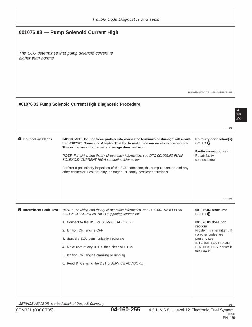
Trouble Code Diagnostics and Tests
RG40854,0000126 –19–19SEP05–1/1
001076.03 — Pump Solenoid Current High
The ECU determines that pump solenoid current ishigher than normal.
04160,255
– – –1/1
001076.03 Pump Solenoid Current High Diagnostic Procedure
– – –1/1
1 Connection Check IMPORTANT: Do not force probes into connector terminals or damage will result.Use JT07328 Connector Adapter Test Kit to make measurements in connectors.This will ensure that terminal damage does not occur.
NOTE: For wiring and theory of operation information, see DTC 001076.03 PUMPSOLENOID CURRENT HIGH supporting information.
Perform a preliminary inspection of the ECU connector, the pump connector, and anyother connector. Look for dirty, damaged, or poorly positioned terminals.
No faulty connection(s):GO TO 2
Faulty connection(s):Repair faultyconnection(s)
– – –1/1
2 Intermittent Fault Test NOTE: For wiring and theory of operation information, see DTC 001076.03 PUMPSOLENOID CURRENT HIGH supporting information.
1. Connect to the DST or SERVICE ADVISOR.
2. Ignition ON, engine OFF
3. Start the ECU communication software
4. Make note of any DTCs, then clear all DTCs
5. Ignition ON, engine cranking or running
6. Read DTCs using the DST orSERVICE ADVISOR.
001076.03 reoccurs:GO TO 3
001076.03 does notreoccur:Problem is intermittent. Ifno other codes arepresent, seeINTERMITTENT FAULTDIAGNOSTICS, earlier inthis Group.
SERVICE ADVISOR is a trademark of Deere & Company
CTM331 (03OCT05) 04-160-255 4.5 L & 6.8 L Level 12 Electronic Fuel System012506
PN=429
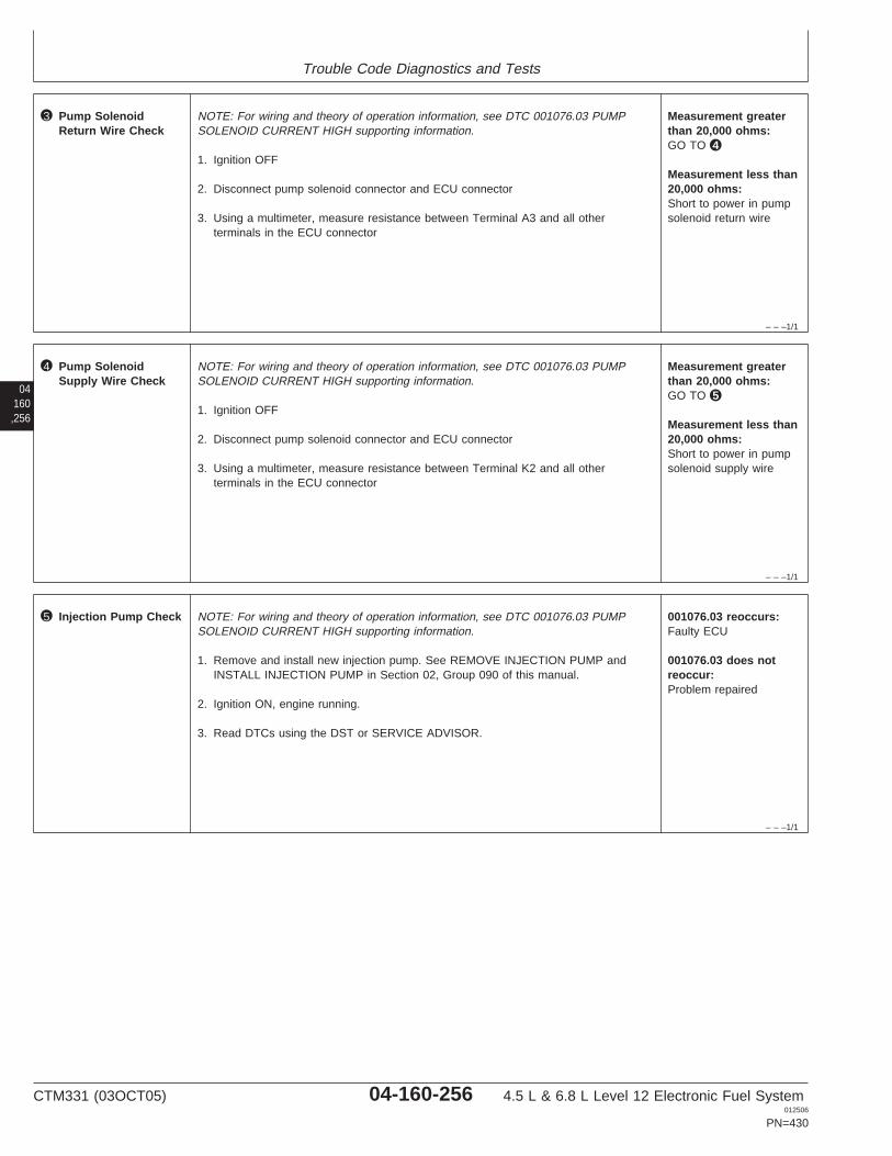
Trouble Code Diagnostics and Tests
– – –1/1
3 Pump SolenoidReturn Wire Check
NOTE: For wiring and theory of operation information, see DTC 001076.03 PUMPSOLENOID CURRENT HIGH supporting information.
1. Ignition OFF
2. Disconnect pump solenoid connector and ECU connector
3. Using a multimeter, measure resistance between Terminal A3 and all otherterminals in the ECU connector
Measurement greaterthan 20,000 ohms:GO TO 4
Measurement less than20,000 ohms:Short to power in pumpsolenoid return wire
04160,256
– – –1/1
4 Pump SolenoidSupply Wire Check
NOTE: For wiring and theory of operation information, see DTC 001076.03 PUMPSOLENOID CURRENT HIGH supporting information.
1. Ignition OFF
2. Disconnect pump solenoid connector and ECU connector
3. Using a multimeter, measure resistance between Terminal K2 and all otherterminals in the ECU connector
Measurement greaterthan 20,000 ohms:GO TO 5
Measurement less than20,000 ohms:Short to power in pumpsolenoid supply wire
– – –1/1
5 Injection Pump Check NOTE: For wiring and theory of operation information, see DTC 001076.03 PUMPSOLENOID CURRENT HIGH supporting information.
1. Remove and install new injection pump. See REMOVE INJECTION PUMP andINSTALL INJECTION PUMP in Section 02, Group 090 of this manual.
2. Ignition ON, engine running.
3. Read DTCs using the DST or SERVICE ADVISOR.
001076.03 reoccurs:Faulty ECU
001076.03 does notreoccur:Problem repaired
CTM331 (03OCT05) 04-160-256 4.5 L & 6.8 L Level 12 Electronic Fuel System012506
PN=430

Trouble Code Diagnostics and Tests
04160,257
CTM331 (03OCT05) 04-160-257 4.5 L & 6.8 L Level 12 Electronic Fuel System012506
PN=431
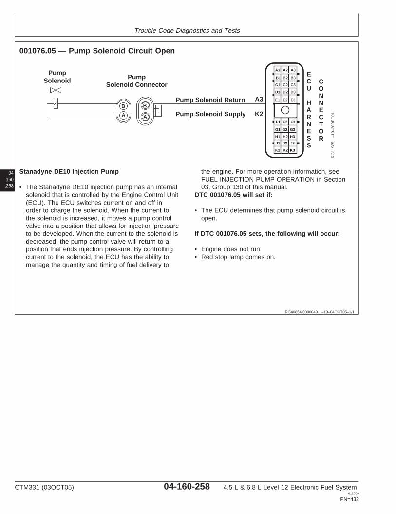
Trouble Code Diagnostics and Tests
04160,258
RG40854,0000049 –19–04OCT05–1/1
001076.05 — Pump Solenoid Circuit Open
A1 A2 A3
B3
C3
D3
E3
B2
C2
D2
E2
B1
C1
D1
E1
F1 F2 F3
G3
H3
J3
K3
G2
H2
J2
K2
G1
H1
J1
K1
Pump Solenoid Return
Pump Solenoid Supply
PumpSolenoid Pump
Solenoid Connector
A3
K2
CONNECTOR
ECU
HARNESS
B
A
B
A
RG
1198
5–1
9–20
DE
C01
Stanadyne DE10 Injection Pump
• The Stanadyne DE10 injection pump has an internalsolenoid that is controlled by the Engine Control Unit(ECU). The ECU switches current on and off inorder to charge the solenoid. When the current tothe solenoid is increased, it moves a pump controlvalve into a position that allows for injection pressureto be developed. When the current to the solenoid isdecreased, the pump control valve will return to aposition that ends injection pressure. By controllingcurrent to the solenoid, the ECU has the ability tomanage the quantity and timing of fuel delivery to
the engine. For more operation information, seeFUEL INJECTION PUMP OPERATION in Section03, Group 130 of this manual.
DTC 001076.05 will set if:
• The ECU determines that pump solenoid circuit isopen.
If DTC 001076.05 sets, the following will occur:
• Engine does not run.• Red stop lamp comes on.
CTM331 (03OCT05) 04-160-258 4.5 L & 6.8 L Level 12 Electronic Fuel System012506
PN=432
Trouble Code Diagnostics and Tests
RG40854,000004C –19–23SEP05–1/1
001076.05 — Pump Solenoid Circuit Open
The ECU determines that pump solenoid circuit isopen.
04160,259
– – –1/1
001076.05 Pump Solenoid Circuit Open Diagnostic Procedure
– – –1/1
1 Connection Check IMPORTANT: Do not force probes into connector terminals or damage will result.Use JT07328 Connector Adapter Test Kit to make measurements in connectors.This will ensure that terminal damage does not occur.
NOTE: For wiring and theory of operation information, see DTC 001076.05 PUMPSOLENOID CIRCUIT OPEN supporting information.
Perform a preliminary inspection of the ECU connector, the pump connector, and anyother connector. Look for dirty, damaged, or poorly positioned terminals.
No faulty connection(s):GO TO 2
Faulty connection(s):Repair faultyconnection(s)
– – –1/1
2 Intermittent Fault Test NOTE: For wiring and theory of operation information, see DTC 001076.05 PUMPSOLENOID CIRCUIT OPEN supporting information.
1. Connect to the DST or SERVICE ADVISOR.
2. Ignition ON, engine OFF
3. Start the ECU communication software
4. Make note of any DTCs, then clear all DTCs
5. Ignition ON, engine cranking or running
6. Read DTCs using the DST orSERVICE ADVISOR.
001076.05 reoccurs:GO TO 3
001076.05 does notreoccur:Problem is intermittent. Ifno other codes arepresent, seeINTERMITTENT FAULTDIAGNOSTICS, earlier inthis Group.
SERVICE ADVISOR is a trademark of Deere & Company
CTM331 (03OCT05) 04-160-259 4.5 L & 6.8 L Level 12 Electronic Fuel System012506
PN=433
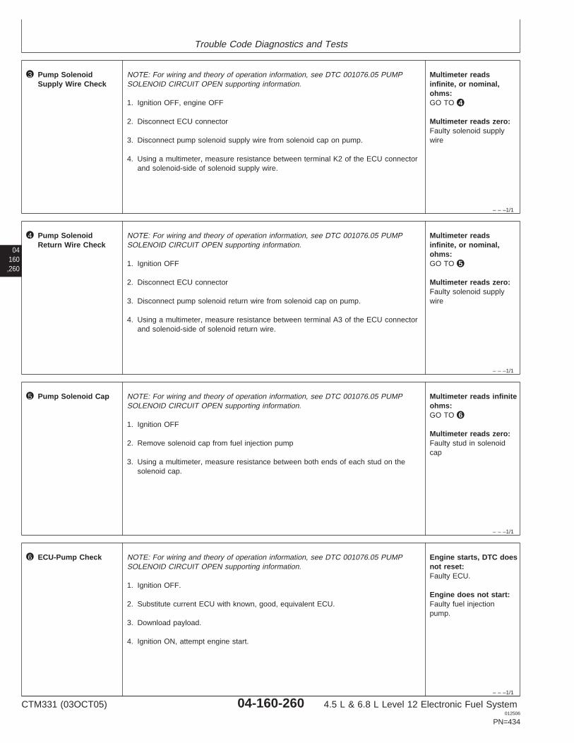
Trouble Code Diagnostics and Tests
– – –1/1
3 Pump SolenoidSupply Wire Check
NOTE: For wiring and theory of operation information, see DTC 001076.05 PUMPSOLENOID CIRCUIT OPEN supporting information.
1. Ignition OFF, engine OFF
2. Disconnect ECU connector
3. Disconnect pump solenoid supply wire from solenoid cap on pump.
4. Using a multimeter, measure resistance between terminal K2 of the ECU connectorand solenoid-side of solenoid supply wire.
Multimeter readsinfinite, or nominal,ohms:GO TO 4
Multimeter reads zero:Faulty solenoid supplywire
04160,260
– – –1/1
4 Pump SolenoidReturn Wire Check
NOTE: For wiring and theory of operation information, see DTC 001076.05 PUMPSOLENOID CIRCUIT OPEN supporting information.
1. Ignition OFF
2. Disconnect ECU connector
3. Disconnect pump solenoid return wire from solenoid cap on pump.
4. Using a multimeter, measure resistance between terminal A3 of the ECU connectorand solenoid-side of solenoid return wire.
Multimeter readsinfinite, or nominal,ohms:GO TO 5
Multimeter reads zero:Faulty solenoid supplywire
– – –1/1
5 Pump Solenoid Cap NOTE: For wiring and theory of operation information, see DTC 001076.05 PUMPSOLENOID CIRCUIT OPEN supporting information.
1. Ignition OFF
2. Remove solenoid cap from fuel injection pump
3. Using a multimeter, measure resistance between both ends of each stud on thesolenoid cap.
Multimeter reads infiniteohms:GO TO 6
Multimeter reads zero:Faulty stud in solenoidcap
– – –1/1
6 ECU-Pump Check NOTE: For wiring and theory of operation information, see DTC 001076.05 PUMPSOLENOID CIRCUIT OPEN supporting information.
1. Ignition OFF.
2. Substitute current ECU with known, good, equivalent ECU.
3. Download payload.
4. Ignition ON, attempt engine start.
Engine starts, DTC doesnot reset:Faulty ECU.
Engine does not start:Faulty fuel injectionpump.
CTM331 (03OCT05) 04-160-260 4.5 L & 6.8 L Level 12 Electronic Fuel System012506
PN=434

Trouble Code Diagnostics and Tests
04160,261
CTM331 (03OCT05) 04-160-261 4.5 L & 6.8 L Level 12 Electronic Fuel System012506
PN=435

Trouble Code Diagnostics and Tests
04160,262
RG40854,000004D –19–04OCT05–1/1
001076.06 — Pump Solenoid Circuit Severely Shorted
A1 A2 A3
B3
C3
D3
E3
B2
C2
D2
E2
B1
C1
D1
E1
F1 F2 F3
G3
H3
J3
K3
G2
H2
J2
K2
G1
H1
J1
K1
Pump Solenoid Return
Pump Solenoid Supply
PumpSolenoid Pump
Solenoid Connector
A3
K2
CONNECTOR
ECU
HARNESS
B
A
B
A
RG
1198
5–1
9–20
DE
C01
Stanadyne DE10 Injection Pump
• The Stanadyne DE10 injection pump has an internalsolenoid that is controlled by the Engine Control Unit(ECU). The ECU switches current on and off inorder to charge the solenoid. When the current tothe solenoid is increased, it moves a pump controlvalve into a position that allows for injection pressureto be developed. When the current to the solenoid isdecreased, the pump control valve will return to aposition that ends injection pressure. By controllingcurrent to the solenoid, the ECU has the ability tomanage the quantity and timing of fuel delivery to
the engine. For more operation information, seeFUEL INJECTION PUMP OPERATION in Section03, Group 130 of this manual.
DTC 001076.06 will set if:
• The ECU determines that pump solenoid circuit isshorted.
If DTC 001076.06 sets, the following will occur:
• ECU will shut engine down immediately.• Red stop lamp comes on.
CTM331 (03OCT05) 04-160-262 4.5 L & 6.8 L Level 12 Electronic Fuel System012506
PN=436
Trouble Code Diagnostics and Tests
RG40854,0000127 –19–23SEP05–1/1
001076.06 — Pump Solenoid Circuit Severely Shorted
The ECU determines that pump solenoid circuit isshorted.
04160,263
– – –1/1
001076.06 Pump Solenoid Circuit Severely Shorted Diagnostic Procedure
– – –1/1
1 Connection Check IMPORTANT: Do not force probes into connector terminals or damage will result.Use JT07328 Connector Adapter Test Kit to make measurements in connectors.This will ensure that terminal damage does not occur.
NOTE: For wiring and theory of operation information, see DTC 001076.06 PUMPSOLENOID CIRCUIT SEVERELY SHORTED supporting information.
Perform a preliminary inspection of the ECU connector, the pump connector, and anyother connector. Look for dirty, damaged, or poorly positioned terminals.
No faulty connection(s):GO TO 2
Faulty connection(s):Repair faultyconnection(s)
– – –1/1
2 Intermittent Fault Test NOTE: For wiring and theory of operation information, see DTC 001076.06 PUMPSOLENOID CIRCUIT SEVERELY SHORTED supporting information.
1. Connect to the DST or SERVICE ADVISOR.
2. Ignition ON, engine OFF
3. Start the ECU communication software
4. Make note of any DTCs, then clear all DTCs
5. Ignition ON, engine cranking or running
6. Read DTCs using the DST orSERVICE ADVISOR.
001076.06 reoccurs:GO TO 3
001076.06 does notreoccur:Problem is intermittent. Ifno other codes arepresent, seeINTERMITTENT FAULTDIAGNOSTICS, earlier inthis Group.
SERVICE ADVISOR is a trademark of Deere & Company
CTM331 (03OCT05) 04-160-263 4.5 L & 6.8 L Level 12 Electronic Fuel System012506
PN=437

Trouble Code Diagnostics and Tests
– – –1/1
3 Pump SolenoidSupply Circuit Check
NOTE: For wiring and theory of operation information, see DTC 001076.06 PUMPSOLENOID CIRCUIT SEVERELY SHORTED supporting information.
1. Ignition OFF
2. Disconnect pump solenoid connector and ECU connector
3. Using a multimeter, measure resistance between terminal K2 of the harness side ofthe ECU connector and:
• A good ground• All other terminals in the ECU connector
Measurement greaterthan 20,000 ohms:GO TO 4
Measurement less than20,000 ohms:Pump solenoid supplywire shorted
04160,264
– – –1/1
4 Pump SolenoidReturn Circuit Check
NOTE: For wiring and theory of operation information, see DTC 001076.06 PUMPSOLENOID CIRCUIT SEVERELY SHORTED supporting information.
1. Ignition OFF
2. Disconnect pump solenoid connector and ECU connector
3. Using a multimeter, measure resistance between terminal A3 of the harness side ofthe ECU connector and:
• A good ground• All other terminals in the ECU connector
Measurement greaterthan 20,000 ohms:GO TO 5
Measurement less than20,000 ohms:Pump solenoid returnwire shorted
– – –1/1
5 Injection Pump Check NOTE: For wiring and theory of operation information, see DTC 001076.06 PUMPSOLENOID CIRCUIT SEVERELY SHORTED supporting information.
1. Remove and install new injection pump. See REMOVE INJECTION PUMP andINSTALL INJECTION PUMP in Section 02, Group 090 of this manual.
2. Ignition ON, engine running.
3. Read DTCs using the DST or SERVICE ADVISOR.
001076.06 reoccurs:Faulty ECU
001076.06 does notreoccur:Problem repaired
CTM331 (03OCT05) 04-160-264 4.5 L & 6.8 L Level 12 Electronic Fuel System012506
PN=438
Trouble Code Diagnostics and Tests
04160,265
CTM331 (03OCT05) 04-160-265 4.5 L & 6.8 L Level 12 Electronic Fuel System012506
PN=439

Trouble Code Diagnostics and Tests
04160,266
RG40854,000004F –19–04OCT05–1/1
001076.07 — Pump Control Valve Closure Not Detected
A1 A2 A3
B3
C3
D3
E3
B2
C2
D2
E2
B1
C1
D1
E1
F1 F2 F3
G3
H3
J3
K3
G2
H2
J2
K2
G1
H1
J1
K1
Pump Solenoid Return
Pump Solenoid Supply
PumpSolenoid Pump
Solenoid Connector
A3
K2
CONNECTOR
ECU
HARNESS
B
A
B
A
RG
1198
5–1
9–20
DE
C01
Stanadyne DE10 Injection Pump
• The Stanadyne DE10 injection pump has an internalsolenoid that is controlled by the Engine Control Unit(ECU). The ECU switches current on and off inorder to charge the solenoid. When the current tothe solenoid is increased, it moves a pump controlvalve into a position that allows for injection pressureto be developed. When the current to the solenoid isdecreased, the pump control valve will return to aposition that ends injection pressure. By controllingcurrent to the solenoid, the ECU has the ability tomanage the quantity and timing of fuel delivery to
the engine. For more operation information, seeFUEL INJECTION PUMP OPERATION in Section03, Group 130 of this manual.
DTC 001076.07 will set if:
• The ECU determines that it can not detect theclosure of the pump control valve.
If DTC 001076.07 sets, the following will occur:
• Engine performance may be erratic.• CAN yellow warning lamp comes on.
CTM331 (03OCT05) 04-160-266 4.5 L & 6.8 L Level 12 Electronic Fuel System012506
PN=440

Trouble Code Diagnostics and Tests
RG40854,0000050 –19–23SEP05–1/1
001076.07 — Pump Control Valve Closure Not Detected
The ECU determines that it can not detect the closureof the pump control valve.
04160,267
– – –1/1
001076.07 Pump Control Valve Closure Not Detected Diagnostic Procedure
– – –1/1
1 Connection Check IMPORTANT: Do not force probes into connector terminals or damage will result.Use JT07328 Connector Adapter Test Kit to make measurements in connectors.This will ensure that terminal damage does not occur.
NOTE: For wiring and theory of operation information, see DTC 001076.07 PUMPCONTROL VALVE CLOSURE NOT DETECTED supporting information.
Perform a preliminary inspection of the ECU connector, the pump connector, and anyother connector. Look for dirty, damaged, or poorly positioned terminals.
No faulty connection(s):GO TO 2
Faulty connection(s):Repair faultyconnection(s)
– – –1/1
2 Intermittent Fault Test NOTE: For wiring and theory of operation information, see DTC 001076.07 PUMPCONTROL VALVE CLOSURE NOT DETECTED supporting information.
1. Connect to the DST or SERVICE ADVISOR.
2. Ignition ON, engine OFF
3. Start the ECU communication software
4. Make note of any DTCs, then clear all DTCs
5. Ignition ON, engine cranking or running
6. Read DTCs using the DST orSERVICE ADVISOR.
001076.07 reoccurs:GO TO 3
001076.07 does notreoccur:Problem is intermittent. Ifno other codes arepresent, seeINTERMITTENT FAULTDIAGNOSTICS, earlier inthis Group.
SERVICE ADVISOR is a trademark of Deere & Company
CTM331 (03OCT05) 04-160-267 4.5 L & 6.8 L Level 12 Electronic Fuel System012506
PN=441
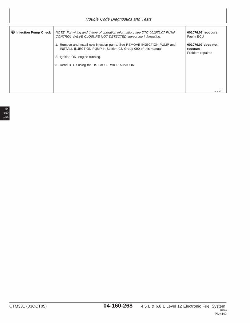
Trouble Code Diagnostics and Tests
– – –1/1
3 Injection Pump Check NOTE: For wiring and theory of operation information, see DTC 001076.07 PUMPCONTROL VALVE CLOSURE NOT DETECTED supporting information.
1. Remove and install new injection pump. See REMOVE INJECTION PUMP andINSTALL INJECTION PUMP in Section 02, Group 090 of this manual.
2. Ignition ON, engine running.
3. Read DTCs using the DST or SERVICE ADVISOR.
001076.07 reoccurs:Faulty ECU
001076.07 does notreoccur:Problem repaired
04160,268
CTM331 (03OCT05) 04-160-268 4.5 L & 6.8 L Level 12 Electronic Fuel System012506
PN=442

Trouble Code Diagnostics and Tests
04160,269
CTM331 (03OCT05) 04-160-269 4.5 L & 6.8 L Level 12 Electronic Fuel System012506
PN=443

Trouble Code Diagnostics and Tests
04160,270
RG40854,0000051 –19–04OCT05–1/1
001076.10 — Pump Solenoid Circuit Moderately Shorted
A1 A2 A3
B3
C3
D3
E3
B2
C2
D2
E2
B1
C1
D1
E1
F1 F2 F3
G3
H3
J3
K3
G2
H2
J2
K2
G1
H1
J1
K1
Pump Solenoid Return
Pump Solenoid Supply
PumpSolenoid Pump
Solenoid Connector
A3
K2
CONNECTOR
ECU
HARNESS
B
A
B
A
RG
1198
5–1
9–20
DE
C01
Stanadyne DE10 Injection Pump
• The Stanadyne DE10 injection pump has an internalsolenoid that is controlled by the Engine Control Unit(ECU). The ECU switches current on and off inorder to charge the solenoid. When the current tothe solenoid is increased, it moves a pump controlvalve into a position that allows for injection pressureto be developed. When the current to the solenoid isdecreased, the pump control valve will return to aposition that ends injection pressure. By controllingcurrent to the solenoid, the ECU has the ability tomanage the quantity and timing of fuel delivery tothe engine. For more operation information, see
FUEL INJECTION PUMP OPERATION in Section03, Group 130 of this manual.
DTC 001076.10 will set if:
• Pump solenoid circuit is moderately shorted topower.
If DTC 001076.10 sets, the following will occur:
• ECU derates engine to 50% of full powerimmediately.
• Red stop light comes on.
CTM331 (03OCT05) 04-160-270 4.5 L & 6.8 L Level 12 Electronic Fuel System012506
PN=444
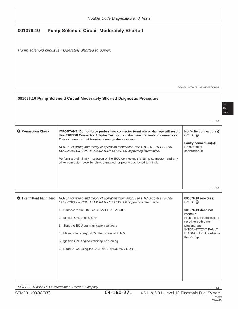
Trouble Code Diagnostics and Tests
RG41221,0000137 –19–23SEP05–1/1
001076.10 — Pump Solenoid Circuit Moderately Shorted
Pump solenoid circuit is moderately shorted to power.
04160,271
– – –1/1
001076.10 Pump Solenoid Circuit Moderately Shorted Diagnostic Procedure
– – –1/1
1 Connection Check IMPORTANT: Do not force probes into connector terminals or damage will result.Use JT07328 Connector Adapter Test Kit to make measurements in connectors.This will ensure that terminal damage does not occur.
NOTE: For wiring and theory of operation information, see DTC 001076.10 PUMPSOLENOID CIRCUIT MODERATELY SHORTED supporting information.
Perform a preliminary inspection of the ECU connector, the pump connector, and anyother connector. Look for dirty, damaged, or poorly positioned terminals.
No faulty connection(s):GO TO 2
Faulty connection(s):Repair faultyconnection(s)
– – –1/1
2 Intermittent Fault Test NOTE: For wiring and theory of operation information, see DTC 001076.10 PUMPSOLENOID CIRCUIT MODERATELY SHORTED supporting information.
1. Connect to the DST or SERVICE ADVISOR.
2. Ignition ON, engine OFF
3. Start the ECU communication software
4. Make note of any DTCs, then clear all DTCs
5. Ignition ON, engine cranking or running
6. Read DTCs using the DST orSERVICE ADVISOR.
001076.10 reoccurs:GO TO 3
001076.10 does notreoccur:Problem is intermittent. Ifno other codes arepresent, seeINTERMITTENT FAULTDIAGNOSTICS, earlier inthis Group.
SERVICE ADVISOR is a trademark of Deere & Company
CTM331 (03OCT05) 04-160-271 4.5 L & 6.8 L Level 12 Electronic Fuel System012506
PN=445
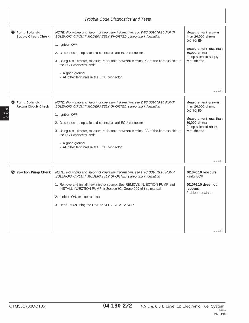
Trouble Code Diagnostics and Tests
– – –1/1
3 Pump SolenoidSupply Circuit Check
NOTE: For wiring and theory of operation information, see DTC 001076.10 PUMPSOLENOID CIRCUIT MODERATELY SHORTED supporting information.
1. Ignition OFF
2. Disconnect pump solenoid connector and ECU connector
3. Using a multimeter, measure resistance between terminal K2 of the harness side ofthe ECU connector and:
• A good ground• All other terminals in the ECU connector
Measurement greaterthan 20,000 ohms:GO TO 4
Measurement less than20,000 ohms:Pump solenoid supplywire shorted
04160,272
– – –1/1
4 Pump SolenoidReturn Circuit Check
NOTE: For wiring and theory of operation information, see DTC 001076.10 PUMPSOLENOID CIRCUIT MODERATELY SHORTED supporting information.
1. Ignition OFF
2. Disconnect pump solenoid connector and ECU connector
3. Using a multimeter, measure resistance between terminal A3 of the harness side ofthe ECU connector and:
• A good ground• All other terminals in the ECU connector
Measurement greaterthan 20,000 ohms:GO TO 5
Measurement less than20,000 ohms:Pump solenoid returnwire shorted
– – –1/1
5 Injection Pump Check NOTE: For wiring and theory of operation information, see DTC 001076.10 PUMPSOLENOID CIRCUIT MODERATELY SHORTED supporting information.
1. Remove and install new injection pump. See REMOVE INJECTION PUMP andINSTALL INJECTION PUMP in Section 02, Group 090 of this manual.
2. Ignition ON, engine running.
3. Read DTCs using the DST or SERVICE ADVISOR.
001076.10 reoccurs:Faulty ECU
001076.10 does notreoccur:Problem repaired
CTM331 (03OCT05) 04-160-272 4.5 L & 6.8 L Level 12 Electronic Fuel System012506
PN=446

Trouble Code Diagnostics and Tests
04160,273
CTM331 (03OCT05) 04-160-273 4.5 L & 6.8 L Level 12 Electronic Fuel System012506
PN=447
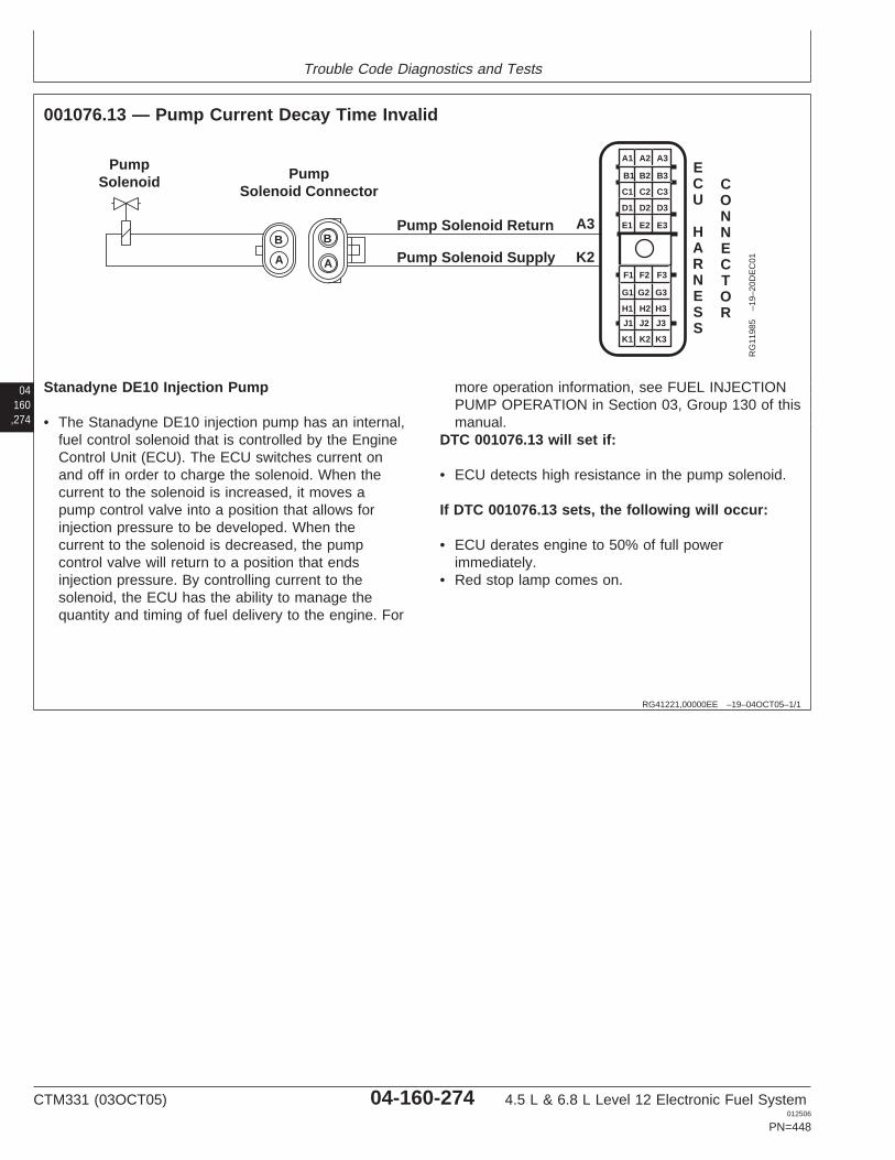
Trouble Code Diagnostics and Tests
04160,274
RG41221,00000EE –19–04OCT05–1/1
001076.13 — Pump Current Decay Time Invalid
A1 A2 A3
B3
C3
D3
E3
B2
C2
D2
E2
B1
C1
D1
E1
F1 F2 F3
G3
H3
J3
K3
G2
H2
J2
K2
G1
H1
J1
K1
Pump Solenoid Return
Pump Solenoid Supply
PumpSolenoid Pump
Solenoid Connector
A3
K2
CONNECTOR
ECU
HARNESS
B
A
B
A
RG
1198
5–1
9–20
DE
C01
Stanadyne DE10 Injection Pump
• The Stanadyne DE10 injection pump has an internal,fuel control solenoid that is controlled by the EngineControl Unit (ECU). The ECU switches current onand off in order to charge the solenoid. When thecurrent to the solenoid is increased, it moves apump control valve into a position that allows forinjection pressure to be developed. When thecurrent to the solenoid is decreased, the pumpcontrol valve will return to a position that endsinjection pressure. By controlling current to thesolenoid, the ECU has the ability to manage thequantity and timing of fuel delivery to the engine. For
more operation information, see FUEL INJECTIONPUMP OPERATION in Section 03, Group 130 of thismanual.
DTC 001076.13 will set if:
• ECU detects high resistance in the pump solenoid.
If DTC 001076.13 sets, the following will occur:
• ECU derates engine to 50% of full powerimmediately.
• Red stop lamp comes on.
CTM331 (03OCT05) 04-160-274 4.5 L & 6.8 L Level 12 Electronic Fuel System012506
PN=448
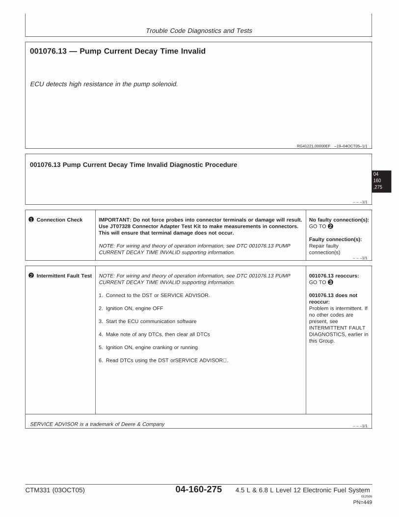
Trouble Code Diagnostics and Tests
RG41221,00000EF –19–04OCT05–1/1
001076.13 — Pump Current Decay Time Invalid
ECU detects high resistance in the pump solenoid.
04160,275
– – –1/1
001076.13 Pump Current Decay Time Invalid Diagnostic Procedure
– – –1/1
1 Connection Check IMPORTANT: Do not force probes into connector terminals or damage will result.Use JT07328 Connector Adapter Test Kit to make measurements in connectors.This will ensure that terminal damage does not occur.
NOTE: For wiring and theory of operation information, see DTC 001076.13 PUMPCURRENT DECAY TIME INVALID supporting information.
No faulty connection(s):GO TO 2
Faulty connection(s):Repair faultyconnection(s)
– – –1/1
2 Intermittent Fault Test NOTE: For wiring and theory of operation information, see DTC 001076.13 PUMPCURRENT DECAY TIME INVALID supporting information.
1. Connect to the DST or SERVICE ADVISOR.
2. Ignition ON, engine OFF
3. Start the ECU communication software
4. Make note of any DTCs, then clear all DTCs
5. Ignition ON, engine cranking or running
6. Read DTCs using the DST orSERVICE ADVISOR.
001076.13 reoccurs:GO TO 3
001076.13 does notreoccur:Problem is intermittent. Ifno other codes arepresent, seeINTERMITTENT FAULTDIAGNOSTICS, earlier inthis Group.
SERVICE ADVISOR is a trademark of Deere & Company
CTM331 (03OCT05) 04-160-275 4.5 L & 6.8 L Level 12 Electronic Fuel System012506
PN=449

Trouble Code Diagnostics and Tests
– – –1/1
3 Pump SolenoidSupply Circuit Check
NOTE: For wiring and theory of operation information, see DTC 001076.13 PUMPCURRENT DECAY TIME INVALID supporting information.
1. Ignition OFF
2. Disconnect pump solenoid connector and ECU connector
3. Using a multimeter, measure resistance between terminal K2 of the harness side ofthe ECU connector and:
• A good ground• All other terminals in the ECU connector
Measurement greaterthan 20,000 ohms:GO TO 4
Measurement less than20,000 ohms:Pump solenoid supplywire shorted
04160,276
– – –1/1
4 Pump SolenoidReturn Circuit Check
NOTE: For wiring and theory of operation information, see DTC 001076.13 PUMPCURRENT DECAY TIME INVALID supporting information.
1. Ignition OFF
2. Disconnect pump solenoid connector and ECU connector
3. Using a multimeter, measure resistance between terminal A3 of the harness side ofthe ECU connector and:
• A good ground• All other terminals in the ECU connector
Measurement greaterthan 20,000 ohms:GO TO 5
Measurement less than20,000 ohms:Pump solenoid returnwire shorted
– – –1/1
5 Injection Pump Check NOTE: For wiring and theory of operation information, see DTC 001076.13 PUMPCURRENT DECAY TIME INVALID supporting information.
1. Remove and install new injection pump. See REMOVE INJECTION PUMP andINSTALL INJECTION PUMP in Section 02, Group 090 of this manual.
2. Ignition ON, engine running.
3. Read DTCs using the DST or SERVICE ADVISOR.
001076.13 reoccurs:Faulty ECU
001076.13 does notreoccur:Problem repaired
CTM331 (03OCT05) 04-160-276 4.5 L & 6.8 L Level 12 Electronic Fuel System012506
PN=450

Trouble Code Diagnostics and Tests
04160,277
CTM331 (03OCT05) 04-160-277 4.5 L & 6.8 L Level 12 Electronic Fuel System012506
PN=451
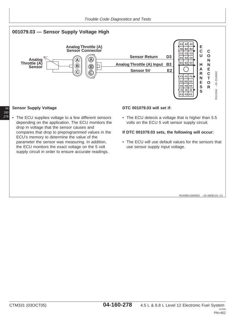
Trouble Code Diagnostics and Tests
04160,278
RG40854,0000052 –19–06DEC01–1/1
001079.03 — Sensor Supply Voltage High
Analog Throttle (A)Sensor Connector
AnalogThrottle (A)
Sensor
A A
B BC C
Sensor Return D3
Analog Throttle (A) Input B3
Sensor 5V E2
A1 A2 A3
B3
C3
D3
E3
B2
C2
D2
E2
B1
C1
D1
E1
F1 F2 F3
G3
H3
J3
K3
G2
H2
J2
K2
G1
H1
J1
K1
ECU
HARNESS
CONNECTOR
RG
1204
4–1
9–23
JAN
02
Sensor Supply Voltage
• The ECU supplies voltage to a few different sensorsdepending on the application. The ECU monitors thedrop in voltage that the sensor causes andcompares that drop to preprogrammed values in theECU’s memory to determine the value of theparameter the sensor was measuring. In addition,the ECU monitors the exact voltage on the 5 voltsupply circuit in order to ensure accurate readings.
DTC 001079.03 will set if:
• The ECU detects a voltage that is higher than 5.5volts on the ECU 5 volt sensor supply circuit.
If DTC 001079.03 sets, the following will occur:
• The ECU will use default values for the sensors thatuse sensor supply input voltage.
CTM331 (03OCT05) 04-160-278 4.5 L & 6.8 L Level 12 Electronic Fuel System012506
PN=452
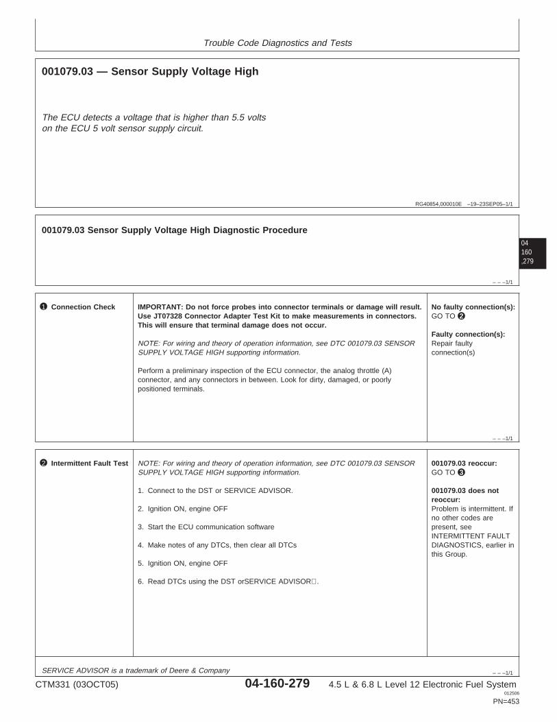
Trouble Code Diagnostics and Tests
RG40854,000010E –19–23SEP05–1/1
001079.03 — Sensor Supply Voltage High
The ECU detects a voltage that is higher than 5.5 voltson the ECU 5 volt sensor supply circuit.
04160,279
– – –1/1
001079.03 Sensor Supply Voltage High Diagnostic Procedure
– – –1/1
1 Connection Check IMPORTANT: Do not force probes into connector terminals or damage will result.Use JT07328 Connector Adapter Test Kit to make measurements in connectors.This will ensure that terminal damage does not occur.
NOTE: For wiring and theory of operation information, see DTC 001079.03 SENSORSUPPLY VOLTAGE HIGH supporting information.
Perform a preliminary inspection of the ECU connector, the analog throttle (A)connector, and any connectors in between. Look for dirty, damaged, or poorlypositioned terminals.
No faulty connection(s):GO TO 2
Faulty connection(s):Repair faultyconnection(s)
– – –1/1
2 Intermittent Fault Test NOTE: For wiring and theory of operation information, see DTC 001079.03 SENSORSUPPLY VOLTAGE HIGH supporting information.
1. Connect to the DST or SERVICE ADVISOR.
2. Ignition ON, engine OFF
3. Start the ECU communication software
4. Make notes of any DTCs, then clear all DTCs
5. Ignition ON, engine OFF
6. Read DTCs using the DST orSERVICE ADVISOR.
001079.03 reoccur:GO TO 3
001079.03 does notreoccur:Problem is intermittent. Ifno other codes arepresent, seeINTERMITTENT FAULTDIAGNOSTICS, earlier inthis Group.
SERVICE ADVISOR is a trademark of Deere & Company
CTM331 (03OCT05) 04-160-279 4.5 L & 6.8 L Level 12 Electronic Fuel System012506
PN=453

Trouble Code Diagnostics and Tests
– – –1/1
3 Sensor Supply WireCheck for Short
NOTE: For wiring and theory of operation information, DTC 001079.03 SENSORSUPPLY VOLTAGE HIGH supporting information.
1. Ignition OFF
2. Disconnect ECU connector
3. Using a multimeter, measure resistance between terminal E2 the harness end ofthe ECU connector and all other terminals in the harness end of the ECU connector
Greater than 20,000ohms:Faulty ECU connectorORFaulty ECU
Less than 20,000 ohms:Short to voltage in sensorsupply wire
04160,280
CTM331 (03OCT05) 04-160-280 4.5 L & 6.8 L Level 12 Electronic Fuel System012506
PN=454
Trouble Code Diagnostics and Tests
04160,281
CTM331 (03OCT05) 04-160-281 4.5 L & 6.8 L Level 12 Electronic Fuel System012506
PN=455

Trouble Code Diagnostics and Tests
04160,282
RG40854,0000054 –19–06DEC01–1/1
001079.04 — Sensor Supply Voltage Low
Analog Throttle (A)Sensor Connector
AnalogThrottle (A)
Sensor
A A
B BC C
Sensor Return D3
Analog Throttle (A) Input B3
Sensor 5V E2
A1 A2 A3
B3
C3
D3
E3
B2
C2
D2
E2
B1
C1
D1
E1
F1 F2 F3
G3
H3
J3
K3
G2
H2
J2
K2
G1
H1
J1
K1
ECU
HARNESS
CONNECTOR
RG
1204
4–1
9–23
JAN
02
Sensor Supply Voltage
• The ECU supplies voltage to a few different sensorsdepending on the application. The ECU monitors thedrop in voltage that the sensor causes andcompares that drop to preprogrammed values in theECU’s memory to determine the value of theparameter the sensor was measuring. In addition,the ECU monitors the exact voltage on the 5 voltsupply circuit in order to ensure accurate readings.
DTC 001079.04 will set if:
• The ECU detects a voltage that is lower than 4.44volts on the ECU 5 volt sensor supply circuit.
If DTC 001079.04 sets, the following will occur:
• The ECU will use default values for the sensors thatuse sensor supply input voltage.
CTM331 (03OCT05) 04-160-282 4.5 L & 6.8 L Level 12 Electronic Fuel System012506
PN=456
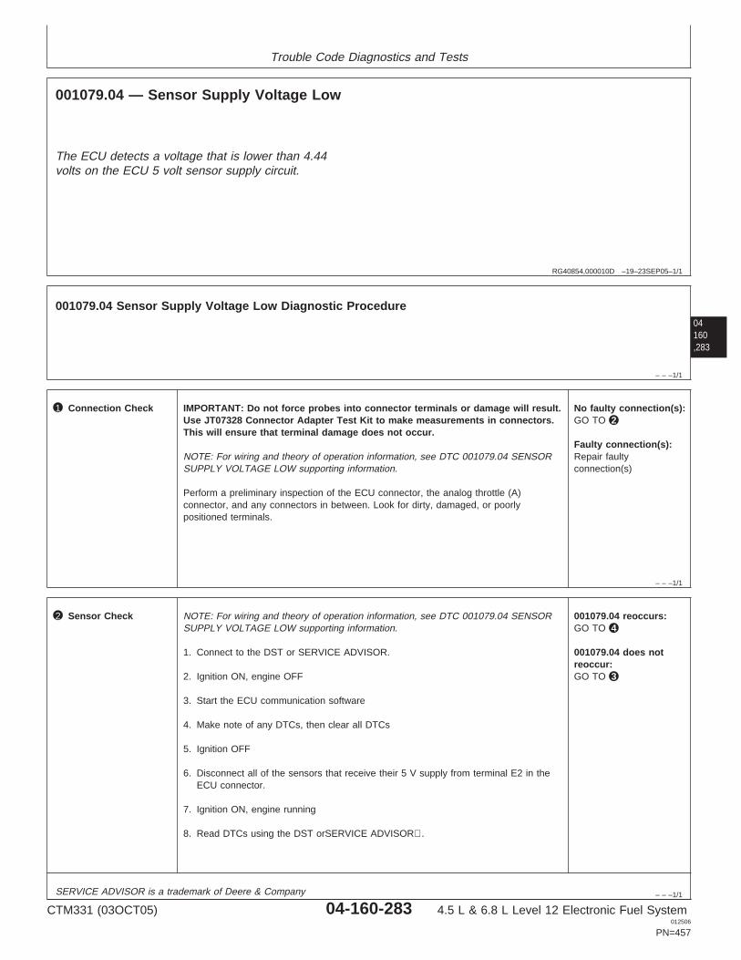
Trouble Code Diagnostics and Tests
RG40854,000010D –19–23SEP05–1/1
001079.04 — Sensor Supply Voltage Low
The ECU detects a voltage that is lower than 4.44volts on the ECU 5 volt sensor supply circuit.
04160,283
– – –1/1
001079.04 Sensor Supply Voltage Low Diagnostic Procedure
– – –1/1
1 Connection Check IMPORTANT: Do not force probes into connector terminals or damage will result.Use JT07328 Connector Adapter Test Kit to make measurements in connectors.This will ensure that terminal damage does not occur.
NOTE: For wiring and theory of operation information, see DTC 001079.04 SENSORSUPPLY VOLTAGE LOW supporting information.
Perform a preliminary inspection of the ECU connector, the analog throttle (A)connector, and any connectors in between. Look for dirty, damaged, or poorlypositioned terminals.
No faulty connection(s):GO TO 2
Faulty connection(s):Repair faultyconnection(s)
– – –1/1
2 Sensor Check NOTE: For wiring and theory of operation information, see DTC 001079.04 SENSORSUPPLY VOLTAGE LOW supporting information.
1. Connect to the DST or SERVICE ADVISOR.
2. Ignition ON, engine OFF
3. Start the ECU communication software
4. Make note of any DTCs, then clear all DTCs
5. Ignition OFF
6. Disconnect all of the sensors that receive their 5 V supply from terminal E2 in theECU connector.
7. Ignition ON, engine running
8. Read DTCs using the DST orSERVICE ADVISOR.
001079.04 reoccurs:GO TO 4
001079.04 does notreoccur:GO TO 3
SERVICE ADVISOR is a trademark of Deere & Company
CTM331 (03OCT05) 04-160-283 4.5 L & 6.8 L Level 12 Electronic Fuel System012506
PN=457
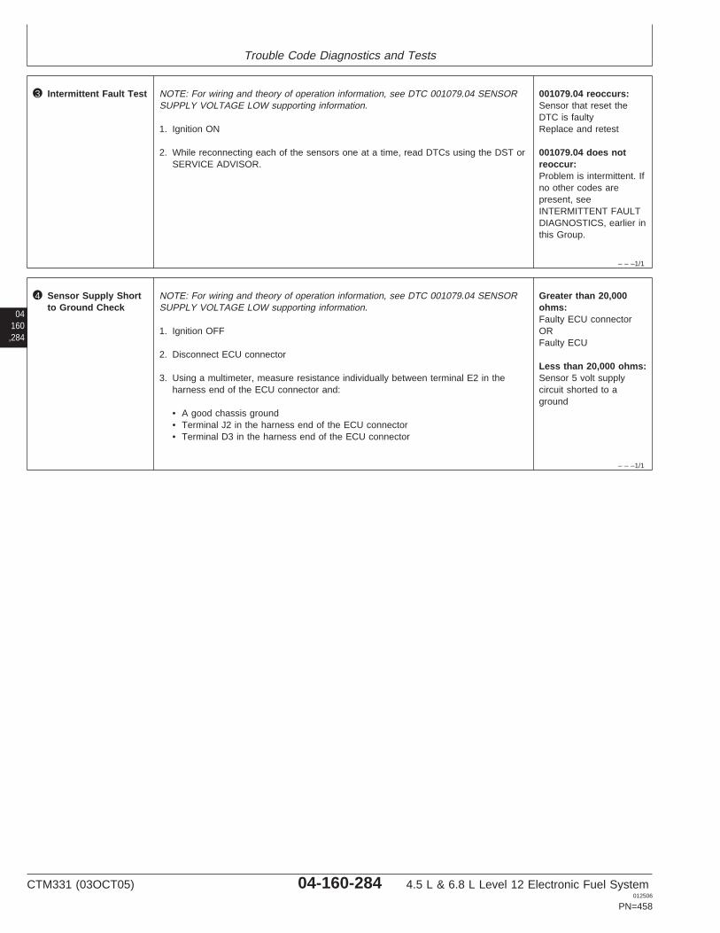
Trouble Code Diagnostics and Tests
– – –1/1
3 Intermittent Fault Test NOTE: For wiring and theory of operation information, see DTC 001079.04 SENSORSUPPLY VOLTAGE LOW supporting information.
1. Ignition ON
2. While reconnecting each of the sensors one at a time, read DTCs using the DST orSERVICE ADVISOR.
001079.04 reoccurs:Sensor that reset theDTC is faultyReplace and retest
001079.04 does notreoccur:Problem is intermittent. Ifno other codes arepresent, seeINTERMITTENT FAULTDIAGNOSTICS, earlier inthis Group.
04160,284
– – –1/1
4 Sensor Supply Shortto Ground Check
NOTE: For wiring and theory of operation information, see DTC 001079.04 SENSORSUPPLY VOLTAGE LOW supporting information.
1. Ignition OFF
2. Disconnect ECU connector
3. Using a multimeter, measure resistance individually between terminal E2 in theharness end of the ECU connector and:
• A good chassis ground• Terminal J2 in the harness end of the ECU connector• Terminal D3 in the harness end of the ECU connector
Greater than 20,000ohms:Faulty ECU connectorORFaulty ECU
Less than 20,000 ohms:Sensor 5 volt supplycircuit shorted to aground
CTM331 (03OCT05) 04-160-284 4.5 L & 6.8 L Level 12 Electronic Fuel System012506
PN=458

Trouble Code Diagnostics and Tests
04160,285
CTM331 (03OCT05) 04-160-285 4.5 L & 6.8 L Level 12 Electronic Fuel System012506
PN=459
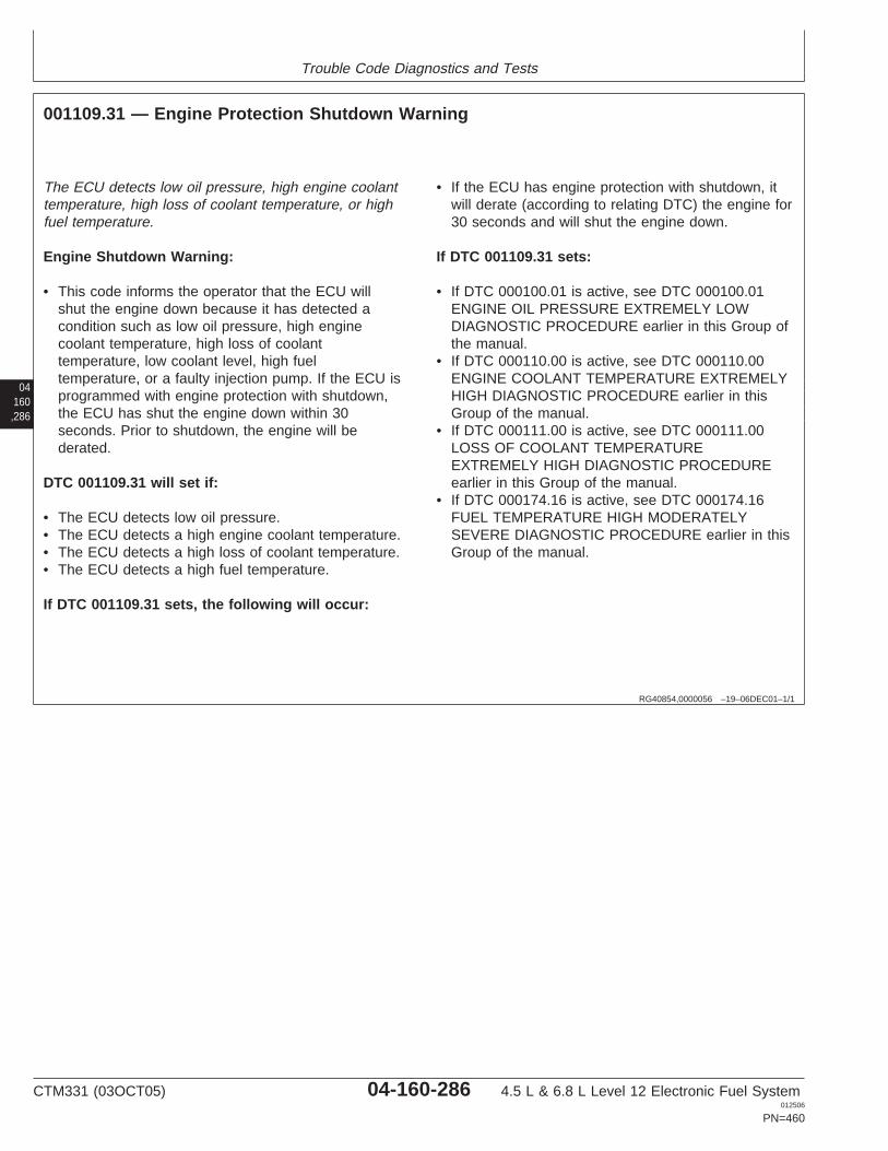
Trouble Code Diagnostics and Tests
04160,286
RG40854,0000056 –19–06DEC01–1/1
001109.31 — Engine Protection Shutdown Warning
The ECU detects low oil pressure, high engine coolanttemperature, high loss of coolant temperature, or highfuel temperature.
Engine Shutdown Warning:
• This code informs the operator that the ECU willshut the engine down because it has detected acondition such as low oil pressure, high enginecoolant temperature, high loss of coolanttemperature, low coolant level, high fueltemperature, or a faulty injection pump. If the ECU isprogrammed with engine protection with shutdown,the ECU has shut the engine down within 30seconds. Prior to shutdown, the engine will bederated.
DTC 001109.31 will set if:
• The ECU detects low oil pressure.• The ECU detects a high engine coolant temperature.• The ECU detects a high loss of coolant temperature.• The ECU detects a high fuel temperature.
If DTC 001109.31 sets, the following will occur:
• If the ECU has engine protection with shutdown, itwill derate (according to relating DTC) the engine for30 seconds and will shut the engine down.
If DTC 001109.31 sets:
• If DTC 000100.01 is active, see DTC 000100.01ENGINE OIL PRESSURE EXTREMELY LOWDIAGNOSTIC PROCEDURE earlier in this Group ofthe manual.
• If DTC 000110.00 is active, see DTC 000110.00ENGINE COOLANT TEMPERATURE EXTREMELYHIGH DIAGNOSTIC PROCEDURE earlier in thisGroup of the manual.
• If DTC 000111.00 is active, see DTC 000111.00LOSS OF COOLANT TEMPERATUREEXTREMELY HIGH DIAGNOSTIC PROCEDUREearlier in this Group of the manual.
• If DTC 000174.16 is active, see DTC 000174.16FUEL TEMPERATURE HIGH MODERATELYSEVERE DIAGNOSTIC PROCEDURE earlier in thisGroup of the manual.
CTM331 (03OCT05) 04-160-286 4.5 L & 6.8 L Level 12 Electronic Fuel System012506
PN=460
Trouble Code Diagnostics and Tests
04160,287
RG40854,0000057 –19–06DEC01–1/1
001110.31 — Engine Protection Shutdown
The ECU detects low oil pressure, high engine coolanttemperature, high loss of coolant temperature, or highfuel temperature.
Engine Protection Shutdown:
• This code informs the operator that the ECU shutthe engine down because it has detected a conditionsuch low oil pressure, high engine coolanttemperature, high loss of coolant temperature, or lowcoolant level. If the ECU is programmed with engineprotection with shutdown, the ECU has shut theengine down.
DTC 001110.31 will set if:
• The ECU detects low oil pressure.• The ECU detects a high engine coolant temperature.• The ECU detects a high loss of coolant temperature.• The ECU detects a high fuel temperature.
If DTC 001110.31 sets, the following will occur:
• The ECU will have shut the engine down.
If DTC 001110.31 sets:
• If DTC 000100.01 is active, see DTC 000100.01ENGINE OIL PRESSURE EXTREMELY LOWDIAGNOSTIC PROCEDURE earlier in this Group ofthe manual.
• If DTC 000110.00 is active, see DTC 000110.00ENGINE COOLANT TEMPERATURE EXTREMELYHIGH DIAGNOSTIC PROCEDURE earlier in thisGroup of the manual.
• If DTC 000111.00 is active, see DTC 000111.00LOSS OF COOLANT TEMPERATUREEXTREMELY HIGH DIAGNOSTIC PROCEDUREearlier in this Group of the manual.
• If DTC 000174.16 is active, see DTC 000174.16FUEL TEMPERATURE HIGH MODERATELYSEVERE DIAGNOSTIC PROCEDURE earlier in thisGroup of the manual.
CTM331 (03OCT05) 04-160-287 4.5 L & 6.8 L Level 12 Electronic Fuel System012506
PN=461
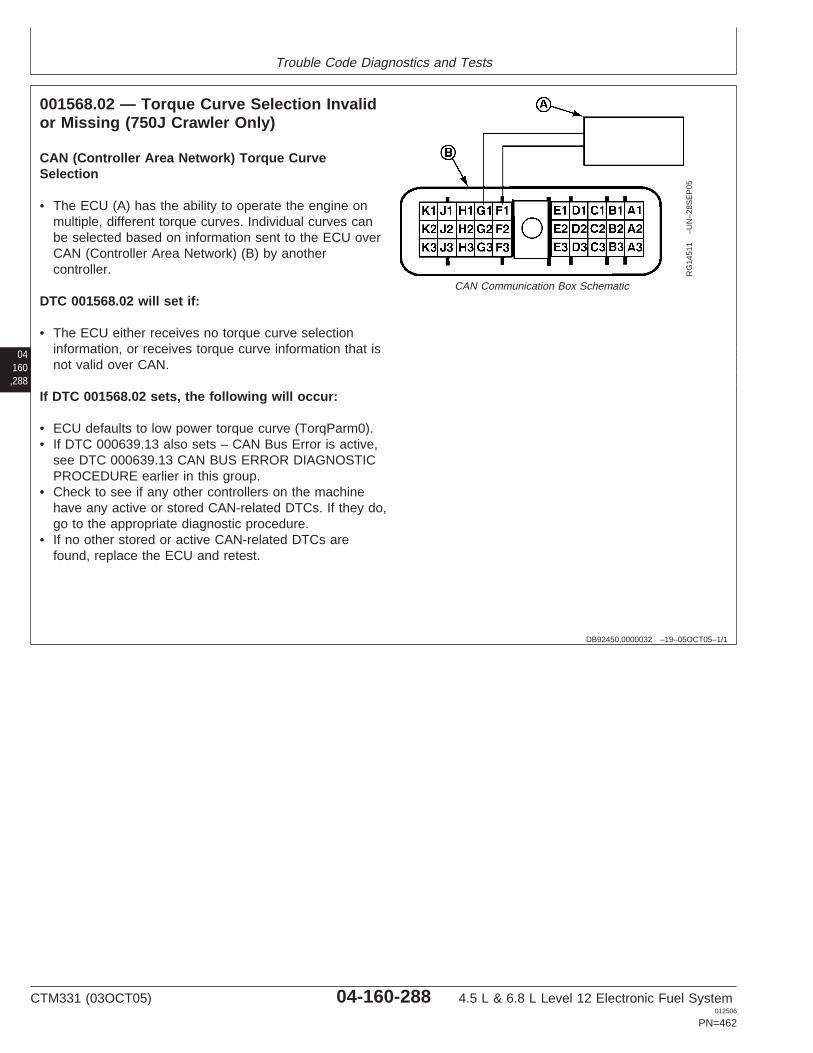
Trouble Code Diagnostics and Tests
04160,288
DB92450,0000032 –19–05OCT05–1/1
001568.02 — Torque Curve Selection Invalidor Missing (750J Crawler Only)
RG
1451
1–U
N–2
8SE
P05
CAN Communication Box Schematic
CAN (Controller Area Network) Torque CurveSelection
• The ECU (A) has the ability to operate the engine onmultiple, different torque curves. Individual curves canbe selected based on information sent to the ECU overCAN (Controller Area Network) (B) by anothercontroller.
DTC 001568.02 will set if:
• The ECU either receives no torque curve selectioninformation, or receives torque curve information that isnot valid over CAN.
If DTC 001568.02 sets, the following will occur:
• ECU defaults to low power torque curve (TorqParm0).• If DTC 000639.13 also sets – CAN Bus Error is active,
see DTC 000639.13 CAN BUS ERROR DIAGNOSTICPROCEDURE earlier in this group.
• Check to see if any other controllers on the machinehave any active or stored CAN-related DTCs. If they do,go to the appropriate diagnostic procedure.
• If no other stored or active CAN-related DTCs arefound, replace the ECU and retest.
CTM331 (03OCT05) 04-160-288 4.5 L & 6.8 L Level 12 Electronic Fuel System012506
PN=462

Trouble Code Diagnostics and Tests
04160,289
CTM331 (03OCT05) 04-160-289 4.5 L & 6.8 L Level 12 Electronic Fuel System012506
PN=463
Trouble Code Diagnostics and Tests
04160,290
RG40854,0000058 –19–06DEC01–1/1
001569.31 — Fuel Derate
The ECU detects low oil pressure, high manifold airtemperature, high engine coolant temperature, highloss of coolant temperature, or high fuel temperature.
Fuel Derate
• The fuel derate trouble code is set to indicate thatthe ECU has detected a condition such as low oilpressure, high manifold air temperature, high coolanttemperature, high loss of coolant temperature, orhigh fuel temperature. If the ECU detects one ofthese conditions, it will begin to derate the amount offuel delivered to the engine.
DTC 001569.31 will set if:
• The ECU detects low oil pressure.• The ECU detects high manifold air temperature.• The ECU detects a high engine coolant temperature.• The ECU detects a high loss of coolant temperature.• The ECU detects a high fuel temperature.
If DTC 001569.31 sets, the following will occur:
• The ECU will limit the amount of fuel available to theengine in an attempt to protect the engine.
If DTC 001569.31 sets:
• If DTC 000100.01 or DTC 000100.18 is active, seeone of the following procedures earlier in this Groupof the manual:
– DTC 000100.01 ENGINE OIL PRESSUREEXTREMELY LOW DIAGNOSTIC PROCEDURE
– DTC 000100.18 ENGINE OIL PRESSUREMODERATELY LOW DIAGNOSTICPROCEDURE
• If DTC 000105.16 is active, see DTC 000105.16MANIFOLD AIR TEMPERATURE MODERATELYHIGH DIAGNOSTIC PROCEDURE earlier in thisGroup of the manual.
• If DTC 000110.00, DTC 000110.15, or DTC000110.16 is active, see one of the followingprocedures earlier in this Group of the manual:– DTC 000110.00 ENGINE COOLANT
TEMPERATURE EXTREMELY HIGHDIAGNOSTIC PROCEDURE
– DTC 000110.15 ENGINE COOLANTTEMPERATURE HIGH LEAST SEVEREDIAGNOSTIC PROCEDURE
– DTC 000110.16 ENGINE COOLANTTEMPERATURE MODERATELY HIGHDIAGNOSTIC PROCEDURE
• If DTC 000111.00 is active, see DTC 000111.00LOSS OF COOLANT TEMPERATUREEXTREMELY HIGH DIAGNOSTIC PROCEDUREearlier in this Group of the manual.
• If DTC 000174.16 is active, see DTC 000174.16FUEL TEMPERATURE HIGH MODERATELYSEVERE DIAGNOSTIC PROCEDURE earlier in thisGroup of the manual.
CTM331 (03OCT05) 04-160-290 4.5 L & 6.8 L Level 12 Electronic Fuel System012506
PN=464
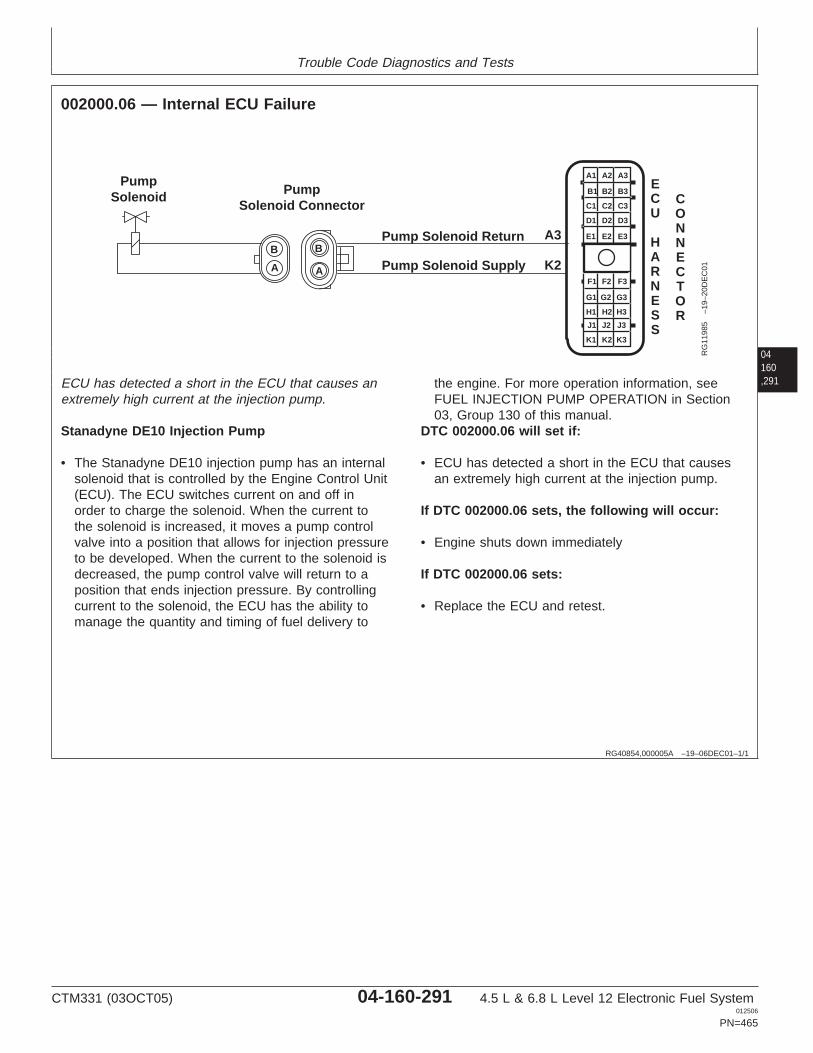
Trouble Code Diagnostics and Tests
04160,291
RG40854,000005A –19–06DEC01–1/1
002000.06 — Internal ECU Failure
A1 A2 A3
B3
C3
D3
E3
B2
C2
D2
E2
B1
C1
D1
E1
F1 F2 F3
G3
H3
J3
K3
G2
H2
J2
K2
G1
H1
J1
K1
Pump Solenoid Return
Pump Solenoid Supply
PumpSolenoid Pump
Solenoid Connector
A3
K2
CONNECTOR
ECU
HARNESS
B
A
B
A
RG
1198
5–1
9–20
DE
C01
ECU has detected a short in the ECU that causes anextremely high current at the injection pump.
Stanadyne DE10 Injection Pump
• The Stanadyne DE10 injection pump has an internalsolenoid that is controlled by the Engine Control Unit(ECU). The ECU switches current on and off inorder to charge the solenoid. When the current tothe solenoid is increased, it moves a pump controlvalve into a position that allows for injection pressureto be developed. When the current to the solenoid isdecreased, the pump control valve will return to aposition that ends injection pressure. By controllingcurrent to the solenoid, the ECU has the ability tomanage the quantity and timing of fuel delivery to
the engine. For more operation information, seeFUEL INJECTION PUMP OPERATION in Section03, Group 130 of this manual.
DTC 002000.06 will set if:
• ECU has detected a short in the ECU that causesan extremely high current at the injection pump.
If DTC 002000.06 sets, the following will occur:
• Engine shuts down immediately
If DTC 002000.06 sets:
• Replace the ECU and retest.
CTM331 (03OCT05) 04-160-291 4.5 L & 6.8 L Level 12 Electronic Fuel System012506
PN=465
Trouble Code Diagnostics and Tests
04160,292
RG40854,000005B –19–06DEC01–1/1
002000.13 — Security Violation
The ECU determines that it, OR another controller onthe machine is not the right controller for the particularmachine.
Security Violation
• When the ignition is first turned on, all of thecontrollers on the machine communicate with eachother to make sure that all controllers are correct forthe particular machine.
DTC 002000.13 will set if:
• The ECU determines that it, OR another controlleron the machine is not the right controller for theparticular machine.
If DTC 002000.13 sets, the following will occur:
• The ECU will allow the engine to start, but will onlyallow low idle engine speed.
• For other applications, see APPLICATIONSPECIFICATIONS in Section 06, Group 210 of thismanual for the high oil pressure input voltagespecification.
If DTC 002000.13 sets:
• If one of the controllers on the machine has justbeen replaced, make sure the correct controller wasinstalled.
• If all controllers on the machine are the correct partnumbers, check to see if any of the controllers haveactive or stored CAN related DTCs. If they do, go tothe appropriate diagnostic procedure.
CTM331 (03OCT05) 04-160-292 4.5 L & 6.8 L Level 12 Electronic Fuel System012506
PN=466
Section 05Tools and Other Materials
Contents
Page
Group 170—Electronic Fuel/Control System RepairTools and Other Materials
Fuel System Repair and AdjustmentEssential Tools . . . . . . . . . . . . . . . . . . . . . .05-170-1
Fuel System Repair and AdjustmentService Equipment and Tools . . . . . . . . . . .05-170-3
Fuel System Repair and Adjustment OtherMaterials . . . . . . . . . . . . . . . . . . . . . . . . . . .05-170-4
Control System Repair and AdjustmentEssential Tools . . . . . . . . . . . . . . . . . . . . . .05-170-5
Control System Repair and Adjustment OtherMaterials . . . . . . . . . . . . . . . . . . . . . . . . . .05-170-10
05Group 180—Diagnostic Service Toolsic Fuel System Diagnostic Tools . . . . . . . . . . .05-180-1
CTM331 (03OCT05) 05-1 4.5 L & 6.8 L Level 12 Electronic Fuel System012506
PN=1
Contents
05
CTM331 (03OCT05) 05-2 4.5 L & 6.8 L Level 12 Electronic Fuel System012506
PN=2
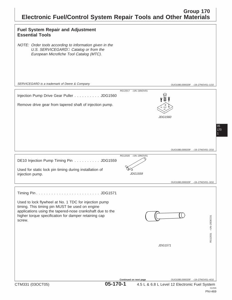
Group 170Electronic Fuel/Control System Repair Tools and Other Materials
OUO1080,000020F –19–27NOV01–1/10
Fuel System Repair and AdjustmentEssential Tools
NOTE: Order tools according to information given in theU.S. SERVICEGARD Catalog or from theEuropean Microfiche Tool Catalog (MTC).
SERVICEGARD is a trademark of Deere & Company
051701
OUO1080,000020F –19–27NOV01–2/10
RG12017 –UN–16NOV01
JDG1560
Injection Pump Drive Gear Puller . . . . . . . . . . JDG1560
Remove drive gear from tapered shaft of injection pump.
OUO1080,000020F –19–27NOV01–3/10
RG12020 –UN–19NOV01
JDG1559
DE10 Injection Pump Timing Pin . . . . . . . . . . JDG1559
Used for static lock pin timing during installation ofinjection pump.
OUO1080,000020F –19–27NOV01–4/10
RG
1203
1–U
N–2
0DE
C01
JDG1571
Timing Pin . . . . . . . . . . . . . . . . . . . . . . . . . JDG1571
Used to lock flywheel at No. 1 TDC for injection pumptiming. This timing pin MUST be used on engineapplications using the tapered-nose crankshaft due to thehigher torque specification for damper retaining capscrew.
CTM331 (03OCT05) 05-170-1 4.5 L & 6.8 L Level 12 Electronic Fuel System012506
PN=469
Continued on next page
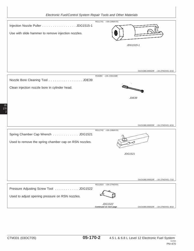
Electronic Fuel/Control System Repair Tools and Other Materials
OUO1080,000020F –19–27NOV01–5/10
RG11741 –UN–24MAY01
JDG1515-1
Injection Nozzle Puller . . . . . . . . . . . . . . . . JDG1515-1
Use with slide hammer to remove injection nozzles.
05170
2
OUO1080,000020F –19–27NOV01–6/10
RG5084 –UN–23AUG88
JDE39
Nozzle Bore Cleaning Tool . . . . . . . . . . . . . . . . JDE39
Clean injection nozzle bore in cylinder head.
OUO1080,000020F –19–27NOV01–7/10
RG11742 –UN–24MAY01
JDG1521
Spring Chamber Cap Wrench . . . . . . . . . . . . JDG1521
Used to remove the spring chamber cap on RSN nozzles.
OUO1080,000020F –19–27NOV01–8/10
RG12023 –UN–27NOV01
JDG1522
Pressure Adjusting Screw Tool . . . . . . . . . . . JDG1522
Used to adjust opening pressure on RSN nozzles.
Continued on next page
CTM331 (03OCT05) 05-170-2 4.5 L & 6.8 L Level 12 Electronic Fuel System012506
PN=470

Electronic Fuel/Control System Repair Tools and Other Materials
OUO1080,000020F –19–27NOV01–9/10
JDG15152 –UN–13JUN01
Pressure Adjusting Screw Lock NutWrench . . . . . . . . . . . . . . . . . . . . . . . . . . JDG1515-2
Used to loosen or tighten lock nut of pressure adjustingscrews.
051703
OUO1080,000020F –19–27NOV01–10/10
RG
6254
–UN
–22J
UL9
2
JD258 (JD-258)
Nozzle Carbon Stop Seal Installer . . . . . JD258 (JD-258)
Used to install carbon stop seal in injection nozzle groove.
OUO1080,0000210 –19–27NOV01–1/3
Fuel System Repair and Adjustment ServiceEquipment and Tools
NOTE: Order tools according to information given in theU.S. SERVICEGARD Catalog or from theEuropean Microfiche Tool Catalog (MTC). Sometools may be available from a local supplier.
SERVICEGARD is a trademark of Deere & Company Continued on next page
CTM331 (03OCT05) 05-170-3 4.5 L & 6.8 L Level 12 Electronic Fuel System012506
PN=471
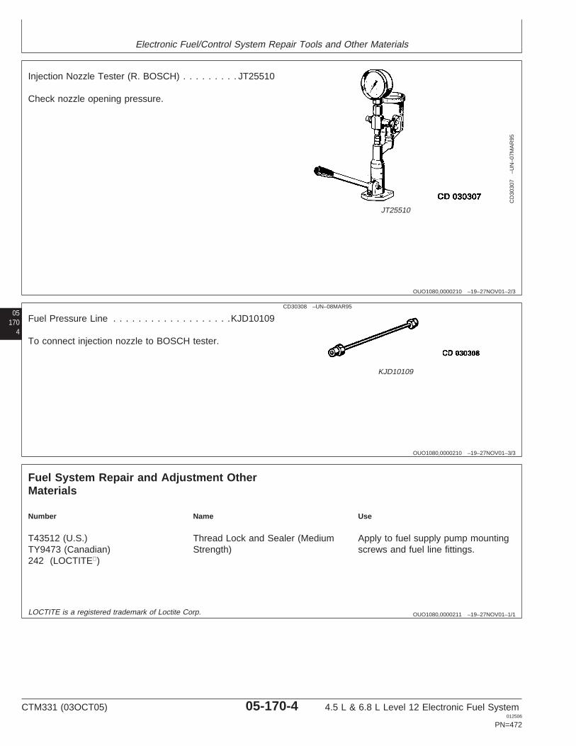
Electronic Fuel/Control System Repair Tools and Other Materials
OUO1080,0000210 –19–27NOV01–2/3
CD
3030
7–U
N–0
7MA
R95
JT25510
Injection Nozzle Tester (R. BOSCH) . . . . . . . . . JT25510
Check nozzle opening pressure.
05170
4
OUO1080,0000210 –19–27NOV01–3/3
CD30308 –UN–08MAR95
KJD10109
Fuel Pressure Line . . . . . . . . . . . . . . . . . . .KJD10109
To connect injection nozzle to BOSCH tester.
OUO1080,0000211 –19–27NOV01–1/1
Fuel System Repair and Adjustment OtherMaterials
Number Name Use
T43512 (U.S.) Thread Lock and Sealer (Medium Apply to fuel supply pump mountingTY9473 (Canadian) Strength) screws and fuel line fittings.242 (LOCTITE)
LOCTITE is a registered trademark of Loctite Corp.
CTM331 (03OCT05) 05-170-4 4.5 L & 6.8 L Level 12 Electronic Fuel System012506
PN=472
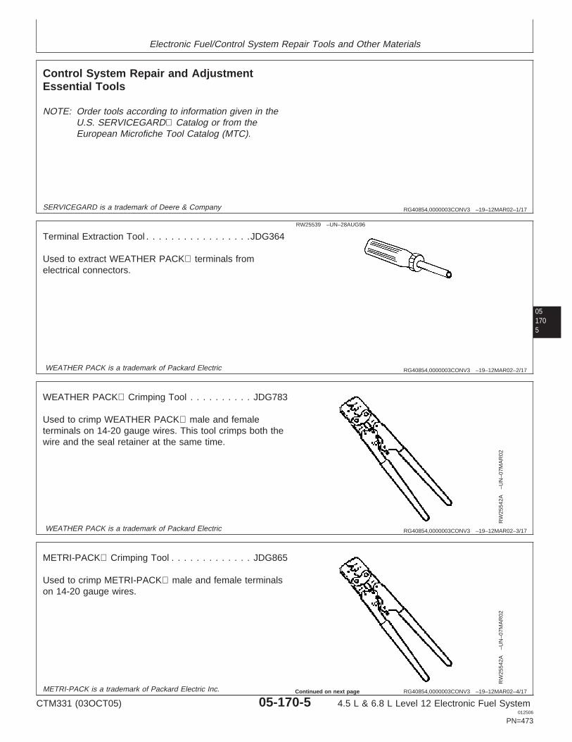
Electronic Fuel/Control System Repair Tools and Other Materials
RG40854,0000003CONV3 –19–12MAR02–1/17
Control System Repair and AdjustmentEssential Tools
NOTE: Order tools according to information given in theU.S. SERVICEGARD Catalog or from theEuropean Microfiche Tool Catalog (MTC).
SERVICEGARD is a trademark of Deere & Company
051705
RG40854,0000003CONV3 –19–12MAR02–2/17
RW25539 –UN–28AUG96
Terminal Extraction Tool . . . . . . . . . . . . . . . . .JDG364
Used to extract WEATHER PACK terminals fromelectrical connectors.
WEATHER PACK is a trademark of Packard Electric
RG40854,0000003CONV3 –19–12MAR02–3/17
RW
2554
2A–U
N–0
7MA
R02
WEATHER PACK Crimping Tool . . . . . . . . . . JDG783
Used to crimp WEATHER PACK male and femaleterminals on 14-20 gauge wires. This tool crimps both thewire and the seal retainer at the same time.
WEATHER PACK is a trademark of Packard Electric
RG40854,0000003CONV3 –19–12MAR02–4/17
RW
2554
2A–U
N–0
7MA
R02
METRI-PACK Crimping Tool . . . . . . . . . . . . . JDG865
Used to crimp METRI-PACK male and female terminalson 14-20 gauge wires.
METRI-PACK is a trademark of Packard Electric Inc.
CTM331 (03OCT05) 05-170-5 4.5 L & 6.8 L Level 12 Electronic Fuel System012506
PN=473
Continued on next page
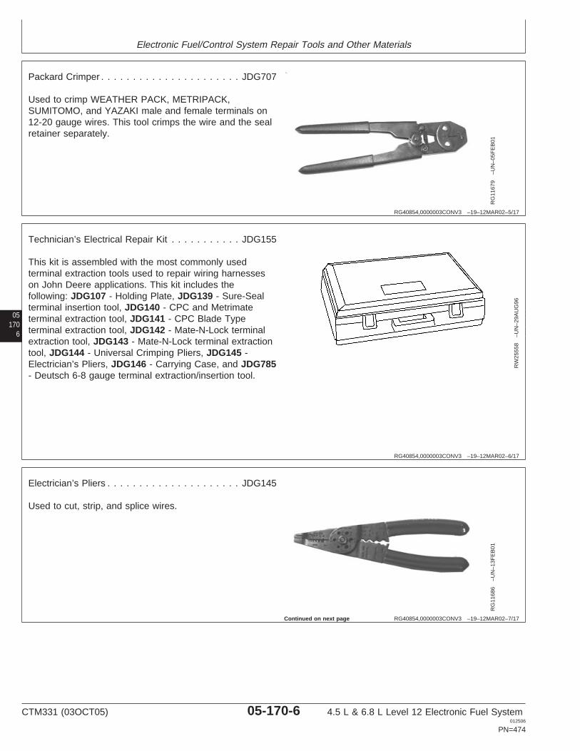
Electronic Fuel/Control System Repair Tools and Other Materials
RG40854,0000003CONV3 –19–12MAR02–5/17
RG
1167
9–U
N–0
5FE
B01
Packard Crimper . . . . . . . . . . . . . . . . . . . . . . JDG707
Used to crimp WEATHER PACK, METRIPACK,SUMITOMO, and YAZAKI male and female terminals on12-20 gauge wires. This tool crimps the wire and the sealretainer separately.
05170
6
RG40854,0000003CONV3 –19–12MAR02–6/17
RW
2555
8–U
N–2
9AU
G96
Technician’s Electrical Repair Kit . . . . . . . . . . . JDG155
This kit is assembled with the most commonly usedterminal extraction tools used to repair wiring harnesseson John Deere applications. This kit includes thefollowing: JDG107 - Holding Plate, JDG139 - Sure-Sealterminal insertion tool, JDG140 - CPC and Metrimateterminal extraction tool, JDG141 - CPC Blade Typeterminal extraction tool, JDG142 - Mate-N-Lock terminalextraction tool, JDG143 - Mate-N-Lock terminal extractiontool, JDG144 - Universal Crimping Pliers, JDG145 -Electrician’s Pliers, JDG146 - Carrying Case, and JDG785- Deutsch 6-8 gauge terminal extraction/insertion tool.
RG40854,0000003CONV3 –19–12MAR02–7/17
RG
1168
6–U
N–1
3FE
B01
Electrician’s Pliers . . . . . . . . . . . . . . . . . . . . . JDG145
Used to cut, strip, and splice wires.
Continued on next page
CTM331 (03OCT05) 05-170-6 4.5 L & 6.8 L Level 12 Electronic Fuel System012506
PN=474
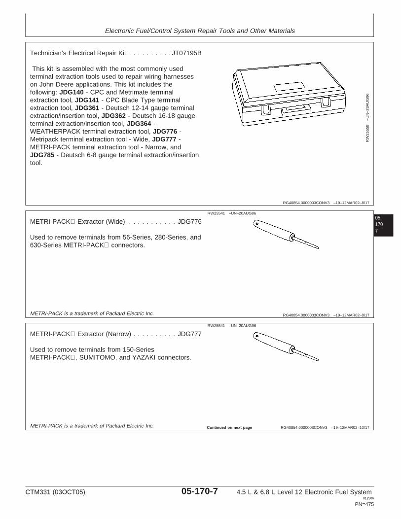
Electronic Fuel/Control System Repair Tools and Other Materials
RG40854,0000003CONV3 –19–12MAR02–8/17
RW
2555
8–U
N–2
9AU
G96
Technician’s Electrical Repair Kit . . . . . . . . . . JT07195B
This kit is assembled with the most commonly usedterminal extraction tools used to repair wiring harnesseson John Deere applications. This kit includes thefollowing: JDG140 - CPC and Metrimate terminalextraction tool, JDG141 - CPC Blade Type terminalextraction tool, JDG361 - Deutsch 12-14 gauge terminalextraction/insertion tool, JDG362 - Deutsch 16-18 gaugeterminal extraction/insertion tool, JDG364 -WEATHERPACK terminal extraction tool, JDG776 -Metripack terminal extraction tool - Wide, JDG777 -METRI-PACK terminal extraction tool - Narrow, andJDG785 - Deutsch 6-8 gauge terminal extraction/insertiontool.
051707
RG40854,0000003CONV3 –19–12MAR02–9/17
RW25541 –UN–20AUG96
METRI-PACK Extractor (Wide) . . . . . . . . . . . JDG776
Used to remove terminals from 56-Series, 280-Series, and630-Series METRI-PACK connectors.
METRI-PACK is a trademark of Packard Electric Inc.
RG40854,0000003CONV3 –19–12MAR02–10/17
RW25541 –UN–20AUG96
METRI-PACK Extractor (Narrow) . . . . . . . . . . JDG777
Used to remove terminals from 150-SeriesMETRI-PACK, SUMITOMO, and YAZAKI connectors.
METRI-PACK is a trademark of Packard Electric Inc. Continued on next page
CTM331 (03OCT05) 05-170-7 4.5 L & 6.8 L Level 12 Electronic Fuel System012506
PN=475
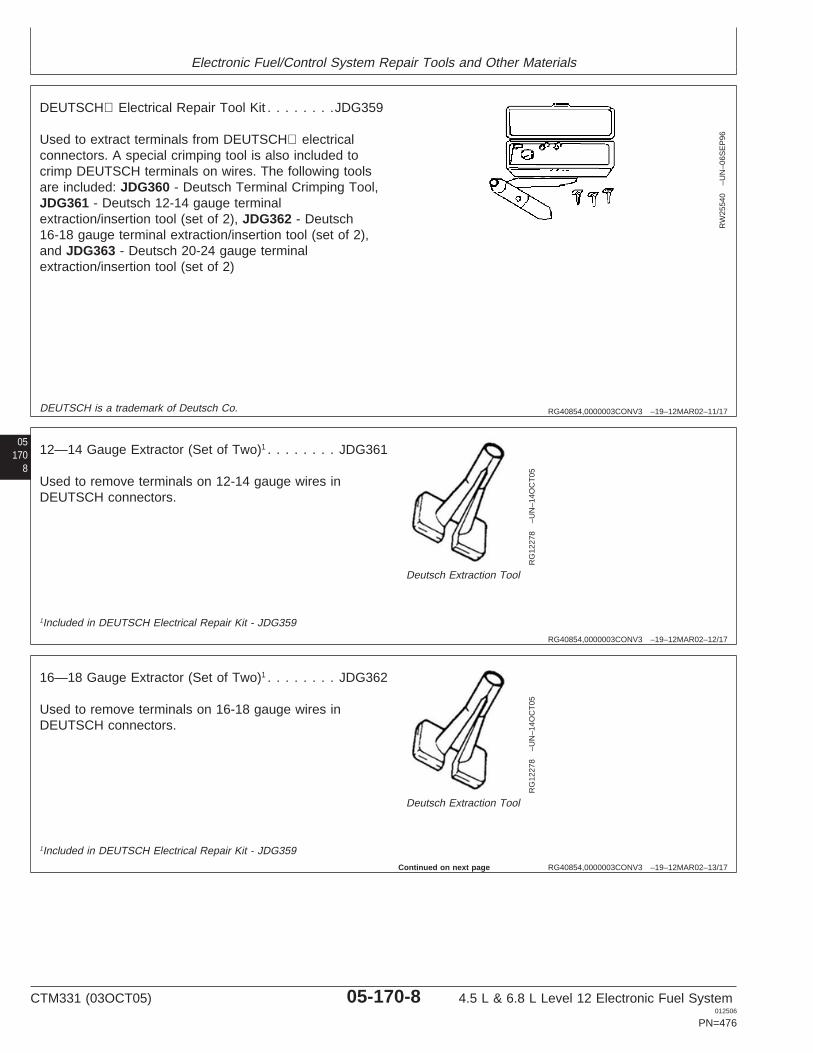
Electronic Fuel/Control System Repair Tools and Other Materials
RG40854,0000003CONV3 –19–12MAR02–11/17
RW
2554
0–U
N–0
6SE
P96
DEUTSCH Electrical Repair Tool Kit . . . . . . . .JDG359
Used to extract terminals from DEUTSCH electricalconnectors. A special crimping tool is also included tocrimp DEUTSCH terminals on wires. The following toolsare included: JDG360 - Deutsch Terminal Crimping Tool,JDG361 - Deutsch 12-14 gauge terminalextraction/insertion tool (set of 2), JDG362 - Deutsch16-18 gauge terminal extraction/insertion tool (set of 2),and JDG363 - Deutsch 20-24 gauge terminalextraction/insertion tool (set of 2)
05170
8
DEUTSCH is a trademark of Deutsch Co.
RG40854,0000003CONV3 –19–12MAR02–12/17
RG
1227
8–U
N–1
4OC
T05
Deutsch Extraction Tool
12—14 Gauge Extractor (Set of Two)1 . . . . . . . . JDG361
Used to remove terminals on 12-14 gauge wires inDEUTSCH connectors.
1Included in DEUTSCH Electrical Repair Kit - JDG359
RG40854,0000003CONV3 –19–12MAR02–13/17
RG
1227
8–U
N–1
4OC
T05
Deutsch Extraction Tool
16—18 Gauge Extractor (Set of Two)1 . . . . . . . . JDG362
Used to remove terminals on 16-18 gauge wires inDEUTSCH connectors.
1Included in DEUTSCH Electrical Repair Kit - JDG359
Continued on next page
CTM331 (03OCT05) 05-170-8 4.5 L & 6.8 L Level 12 Electronic Fuel System012506
PN=476
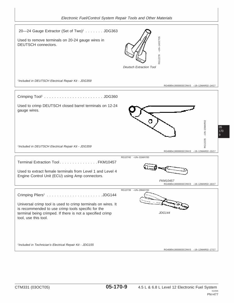
Electronic Fuel/Control System Repair Tools and Other Materials
RG40854,0000003CONV3 –19–12MAR02–14/17
RG
1227
8–U
N–1
4OC
T05
Deutsch Extraction Tool
20—24 Gauge Extractor (Set of Two)1 . . . . . . . JDG363
Used to remove terminals on 20-24 gauge wires inDEUTSCH connectors.
1Included in DEUTSCH Electrical Repair Kit - JDG359
051709
RG40854,0000003CONV3 –19–12MAR02–15/17
RG
1223
5–U
N–1
5MA
R02
Crimping Tool1 . . . . . . . . . . . . . . . . . . . . . . . JDG360
Used to crimp DEUTSCH closed barrel terminals on 12-24gauge wires.
1Included in DEUTSCH Electrical Repair Kit - JDG359
RG40854,0000003CONV3 –19–12MAR02–16/17
RG10740 –UN–31MAY00
FKM10457
Terminal Extraction Tool . . . . . . . . . . . . . . . FKM10457
Used to extract female terminals from Level 1 and Level 4Engine Control Unit (ECU) using Amp connectors.
RG40854,0000003CONV3 –19–12MAR02–17/17
RG10739 –UN–26MAY00
JDG144
Crimping Pliers1 . . . . . . . . . . . . . . . . . . . . . .JDG144
Universal crimp tool is used to crimp terminals on wires. Itis recommended to use crimp tools specific for theterminal being crimped. If there is not a specified crimptool, use this tool.
1Included in Technician’s Electrical Repair Kit - JDG155
CTM331 (03OCT05) 05-170-9 4.5 L & 6.8 L Level 12 Electronic Fuel System012506
PN=477
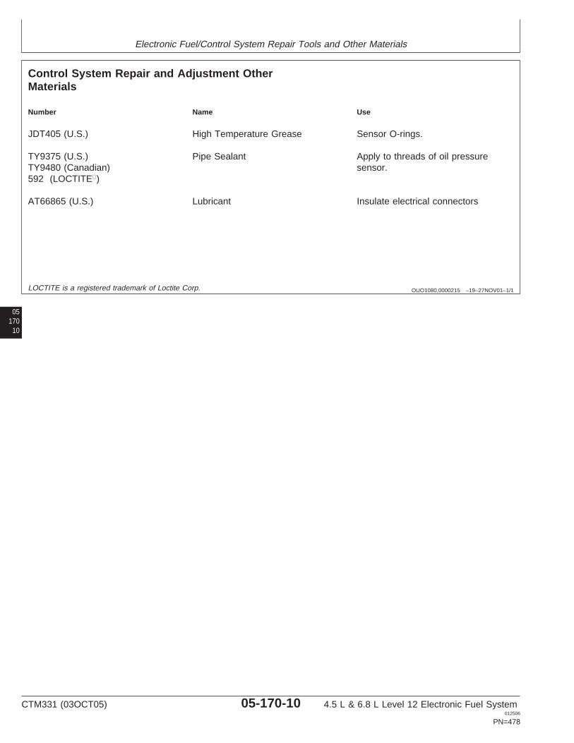
Electronic Fuel/Control System Repair Tools and Other Materials
OUO1080,0000215 –19–27NOV01–1/1
Control System Repair and Adjustment OtherMaterials
Number Name Use
JDT405 (U.S.) High Temperature Grease Sensor O-rings.
TY9375 (U.S.) Pipe Sealant Apply to threads of oil pressureTY9480 (Canadian) sensor.592 (LOCTITE)
AT66865 (U.S.) Lubricant Insulate electrical connectors
05170
10
LOCTITE is a registered trademark of Loctite Corp.
CTM331 (03OCT05) 05-170-10 4.5 L & 6.8 L Level 12 Electronic Fuel System012506
PN=478
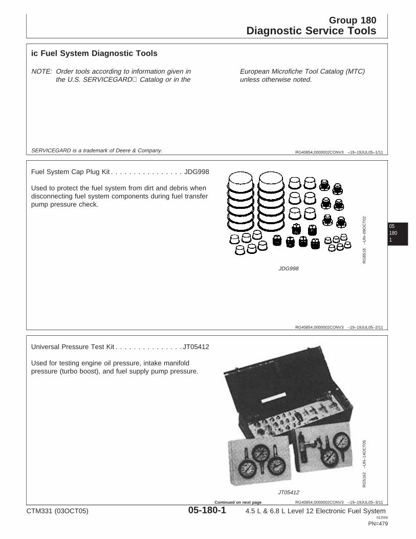
Group 180Diagnostic Service Tools
RG40854,0000002CONV3 –19–19JUL05–1/11
ic Fuel System Diagnostic Tools
NOTE: Order tools according to information given inthe U.S. SERVICEGARD Catalog or in the
European Microfiche Tool Catalog (MTC)unless otherwise noted.
SERVICEGARD is a trademark of Deere & Company.
051801
RG40854,0000002CONV3 –19–19JUL05–2/11
RG
8518
–UN
–09O
CT
02
JDG998
Fuel System Cap Plug Kit . . . . . . . . . . . . . . . . JDG998
Used to protect the fuel system from dirt and debris whendisconnecting fuel system components during fuel transferpump pressure check.
RG40854,0000002CONV3 –19–19JUL05–3/11
RG
5162
–UN
–14O
CT
05
JT05412
Universal Pressure Test Kit . . . . . . . . . . . . . . . JT05412
Used for testing engine oil pressure, intake manifoldpressure (turbo boost), and fuel supply pump pressure.
CTM331 (03OCT05) 05-180-1 4.5 L & 6.8 L Level 12 Electronic Fuel System012506
PN=479
Continued on next page
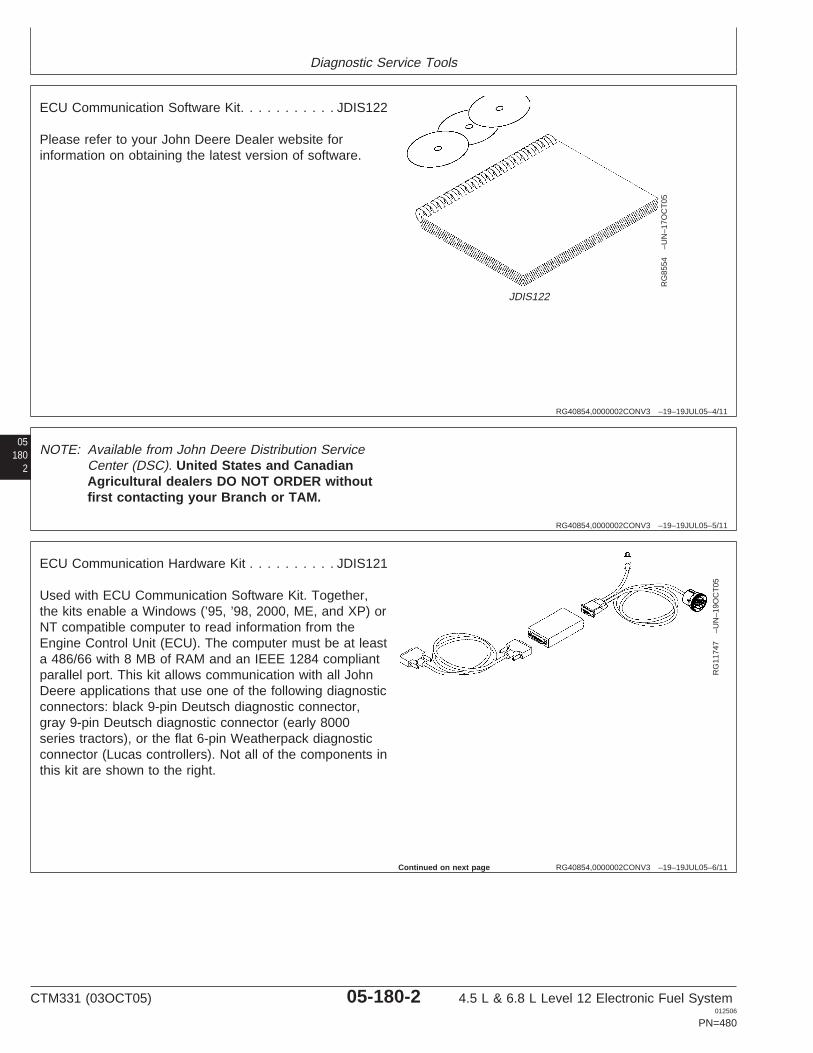
Diagnostic Service Tools
RG40854,0000002CONV3 –19–19JUL05–4/11
RG
8554
–UN
–17O
CT
05
JDIS122
ECU Communication Software Kit. . . . . . . . . . . JDIS122
Please refer to your John Deere Dealer website forinformation on obtaining the latest version of software.
05180
2
RG40854,0000002CONV3 –19–19JUL05–5/11
NOTE: Available from John Deere Distribution ServiceCenter (DSC). United States and CanadianAgricultural dealers DO NOT ORDER withoutfirst contacting your Branch or TAM.
RG40854,0000002CONV3 –19–19JUL05–6/11
RG
1174
7–U
N–1
9OC
T05
ECU Communication Hardware Kit . . . . . . . . . . JDIS121
Used with ECU Communication Software Kit. Together,the kits enable a Windows (’95, ’98, 2000, ME, and XP) orNT compatible computer to read information from theEngine Control Unit (ECU). The computer must be at leasta 486/66 with 8 MB of RAM and an IEEE 1284 compliantparallel port. This kit allows communication with all JohnDeere applications that use one of the following diagnosticconnectors: black 9-pin Deutsch diagnostic connector,gray 9-pin Deutsch diagnostic connector (early 8000series tractors), or the flat 6-pin Weatherpack diagnosticconnector (Lucas controllers). Not all of the components inthis kit are shown to the right.
Continued on next page
CTM331 (03OCT05) 05-180-2 4.5 L & 6.8 L Level 12 Electronic Fuel System012506
PN=480
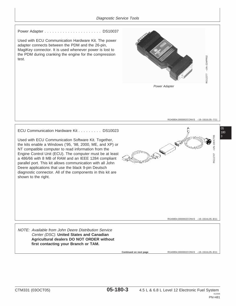
Diagnostic Service Tools
RG40854,0000002CONV3 –19–19JUL05–7/11
RG
1227
7–U
N–2
2AP
R02
Power Adapter
Power Adapter . . . . . . . . . . . . . . . . . . . . . . DS10037
Used with ECU Communication Hardware Kit. The poweradapter connects between the PDM and the 26-pin,MagiKey connector. It is used whenever power is lost tothe PDM during cranking the engine for the compressiontest.
051803
RG40854,0000002CONV3 –19–19JUL05–8/11
RG
1174
7–U
N–1
9OC
T05
ECU Communication Hardware Kit . . . . . . . . . DS10023
Used with ECU Communication Software Kit. Together,the kits enable a Windows (’95, ’98, 2000, ME, and XP) orNT compatible computer to read information from theEngine Control Unit (ECU). The computer must be at leasta 486/66 with 8 MB of RAM and an IEEE 1284 compliantparallel port. This kit allows communication with all JohnDeere applications that use the black 9-pin Deutschdiagnostic connector. All of the components in this kit areshown to the right.
RG40854,0000002CONV3 –19–19JUL05–9/11
NOTE: Available from John Deere Distribution ServiceCenter (DSC). United States and CanadianAgricultural dealers DO NOT ORDER withoutfirst contacting your Branch or TAM.
Continued on next page
CTM331 (03OCT05) 05-180-3 4.5 L & 6.8 L Level 12 Electronic Fuel System012506
PN=481
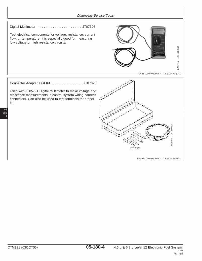
Diagnostic Service Tools
RG40854,0000002CONV3 –19–19JUL05–10/11
RG
1112
6–U
N–1
9JU
N00
Digital Multimeter . . . . . . . . . . . . . . . . . . . . JT07306
Test electrical components for voltage, resistance, currentflow, or temperature. It is especially good for measuringlow voltage or high resistance circuits.
05180
4
RG40854,0000002CONV3 –19–19JUL05–11/11
RG
8803
–UN
–26N
OV
97
JT07328
Connector Adapter Test Kit . . . . . . . . . . . . . . . JT07328
Used with JT05791 Digital Multimeter to make voltage andresistance measurements in control system wiring harnessconnectors. Can also be used to test terminals for properfit.
CTM331 (03OCT05) 05-180-4 4.5 L & 6.8 L Level 12 Electronic Fuel System012506
PN=482
Section 06Specifications
Contents
Page Page
Group 200—Repair Specifications OEM Engines - Electronic Control SystemUnified Inch Bolt and Screw Torque Wiring Diagram - Extended ECUs
Values . . . . . . . . . . . . . . . . . . . . . . . . . . . . .06-200-1 (Later) . . . . . . . . . . . . . . . . . . . . . . . . . . . .06-210-34Metric Bolt and Screw Torque Values . . . . . . .06-200-2 OEM Engines - 4.5L & 6.8L InstrumentGeneral OEM Engine Specifications . . . . . . . .06-200-3 Panel/Engine Start Components Electrical WiringElectronic Fuel System Repair and Diagram. . . . . . . . . . . . . . . . . . . . . . . . . . .06-210-35
Adjustment Specifications . . . . . . . . . . . . . .06-200-4 Skidders - Sensor Specifications . . . . . . . . . .06-210-36Electronic Engine Control Repair and Skidders - Torque Curve Selection . . . . . . . .06-210-38
Adjustment Specifications . . . . . . . . . . . . . .06-200-6 Skidders - Governor Mode Selection. . . . . . .06-210-38Skidders - ECU Terminal Identification . . . . .06-210-39Group 210—Diagnostic SpecificationsTelehandlers - Sensor Specifications . . . . . .06-210-40Group 150/160 Electronic Fuel SystemTelehandlers - Torque Curve Selection . . . . .06-210-42Diagnostic Specifications . . . . . . . . . . . . . . .06-210-1Telehandlers - Governor Mode Selection . . .06-210-42Application Specifications . . . . . . . . . . . . . . . .06-210-3Telehandlers - ECU TerminalBackhoes - Sensor Specifications . . . . . . . . . .06-210-6
Identification . . . . . . . . . . . . . . . . . . . . . . .06-210-43Backhoes - Torque Curve Selection . . . . . . . .06-210-7Tractors - Sensor Specifications . . . . . . . . . .06-210-44Backhoes - Governor Mode Selection . . . . . . .06-210-7Tractors - Torque Curve Selection. . . . . . . . .06-210-46Backhoes - ECU Terminal Identification . . . . .06-210-8Tractors - Governor Mode Selection . . . . . . .06-210-46Crawlers - Sensor Specifications. . . . . . . . . .06-210-10 06Tractors - ECU Terminal Identification. . . . . .06-210-47Crawlers - Torque Curve Selection . . . . . . . .06-210-12
Crawlers - Governor Mode Selection. . . . . . .06-210-12Crawlers - ECU Terminal Identification . . . . .06-210-13Excavators - Sensor Specifications . . . . . . . .06-210-14Excavators - Torque Curve Selection . . . . . .06-210-15Excavators - Governor Mode Selection . . . . .06-210-15Excavators - ECU Terminal Identification . . .06-210-16Forwarders - Sensor Specifications . . . . . . . .06-210-18Forwarders - Torque Curve Selection . . . . . .06-210-20Forwarders - Governor Mode Selection. . . . .06-210-20Forwarders - ECU Terminal Identification . . .06-210-21Harvesters - Sensor Specifications . . . . . . . .06-210-22Harvesters - Torque Curve Selection . . . . . .06-210-23Harvesters - Governor Mode Selection . . . . .06-210-23Harvesters - ECU Terminal Identification. . . .06-210-24OEM Engines - Sensor Specifications . . . . . .06-210-26OEM Engines - Torque Curve Selection . . . .06-210-28OEM Engines - Governor Mode Selection
With OC03038 Software or Later . . . . . . . .06-210-29OEM Engines - Governor Mode Selection
With OC03033 Software or Earlier . . . . . . .06-210-30OEM Engines - ECU Terminal
Identification . . . . . . . . . . . . . . . . . . . . . . .06-210-31OEM Engines - Electronic Control System
Wiring Diagram - Base ECUs . . . . . . . . . .06-210-32OEM Engines - Electronic Control System
Wiring Diagram - Extended ECUs(Early) . . . . . . . . . . . . . . . . . . . . . . . . . . . .06-210-33
CTM331 (03OCT05) 06-1 4.5 L & 6.8 L Level 12 Electronic Fuel System012506
PN=1
Contents
06
CTM331 (03OCT05) 06-2 4.5 L & 6.8 L Level 12 Electronic Fuel System012506
PN=2
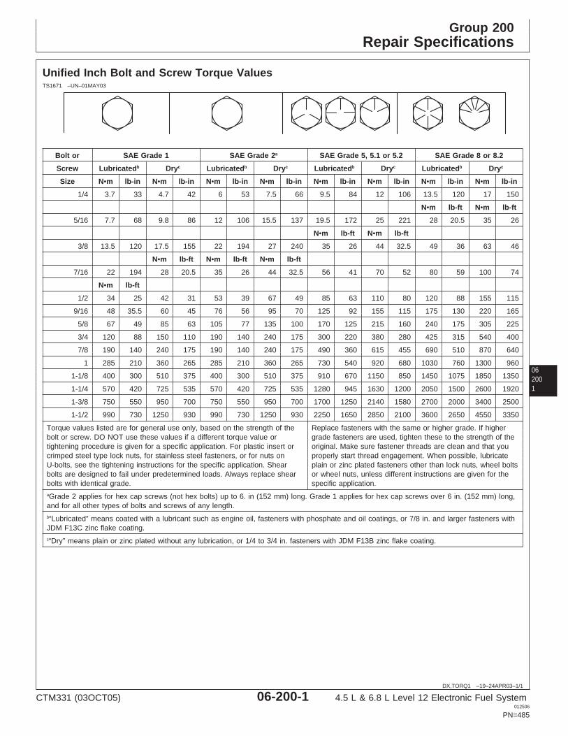
Group 200Repair Specifications
062001
DX,TORQ1 –19–24APR03–1/1
Unified Inch Bolt and Screw Torque ValuesTS1671 –UN–01MAY03
Bolt or SAE Grade 1 SAE Grade 2a SAE Grade 5, 5.1 or 5.2 SAE Grade 8 or 8.2
Screw Lubricatedb Dryc Lubricatedb Dryc Lubricatedb Dryc Lubricatedb Dryc
Size N•m lb-in N•m lb-in N•m lb-in N•m lb-in N•m lb-in N•m lb-in N•m lb-in N•m lb-in
1/4 3.7 33 4.7 42 6 53 7.5 66 9.5 84 12 106 13.5 120 17 150
N•m lb-ft N•m lb-ft
5/16 7.7 68 9.8 86 12 106 15.5 137 19.5 172 25 221 28 20.5 35 26
N•m lb-ft N•m lb-ft
3/8 13.5 120 17.5 155 22 194 27 240 35 26 44 32.5 49 36 63 46
N•m lb-ft N•m lb-ft N•m lb-ft
7/16 22 194 28 20.5 35 26 44 32.5 56 41 70 52 80 59 100 74
N•m lb-ft
1/2 34 25 42 31 53 39 67 49 85 63 110 80 120 88 155 115
9/16 48 35.5 60 45 76 56 95 70 125 92 155 115 175 130 220 165
5/8 67 49 85 63 105 77 135 100 170 125 215 160 240 175 305 225
3/4 120 88 150 110 190 140 240 175 300 220 380 280 425 315 540 400
7/8 190 140 240 175 190 140 240 175 490 360 615 455 690 510 870 640
1 285 210 360 265 285 210 360 265 730 540 920 680 1030 760 1300 960
1-1/8 400 300 510 375 400 300 510 375 910 670 1150 850 1450 1075 1850 1350
1-1/4 570 420 725 535 570 420 725 535 1280 945 1630 1200 2050 1500 2600 1920
1-3/8 750 550 950 700 750 550 950 700 1700 1250 2140 1580 2700 2000 3400 2500
1-1/2 990 730 1250 930 990 730 1250 930 2250 1650 2850 2100 3600 2650 4550 3350
Torque values listed are for general use only, based on the strength of the Replace fasteners with the same or higher grade. If higherbolt or screw. DO NOT use these values if a different torque value or grade fasteners are used, tighten these to the strength of thetightening procedure is given for a specific application. For plastic insert or original. Make sure fastener threads are clean and that youcrimped steel type lock nuts, for stainless steel fasteners, or for nuts on properly start thread engagement. When possible, lubricateU-bolts, see the tightening instructions for the specific application. Shear plain or zinc plated fasteners other than lock nuts, wheel boltsbolts are designed to fail under predetermined loads. Always replace shear or wheel nuts, unless different instructions are given for thebolts with identical grade. specific application.aGrade 2 applies for hex cap screws (not hex bolts) up to 6. in (152 mm) long. Grade 1 applies for hex cap screws over 6 in. (152 mm) long,and for all other types of bolts and screws of any length.b“Lubricated” means coated with a lubricant such as engine oil, fasteners with phosphate and oil coatings, or 7/8 in. and larger fasteners withJDM F13C zinc flake coating.c“Dry” means plain or zinc plated without any lubrication, or 1/4 to 3/4 in. fasteners with JDM F13B zinc flake coating.
CTM331 (03OCT05) 06-200-1 4.5 L & 6.8 L Level 12 Electronic Fuel System012506
PN=485
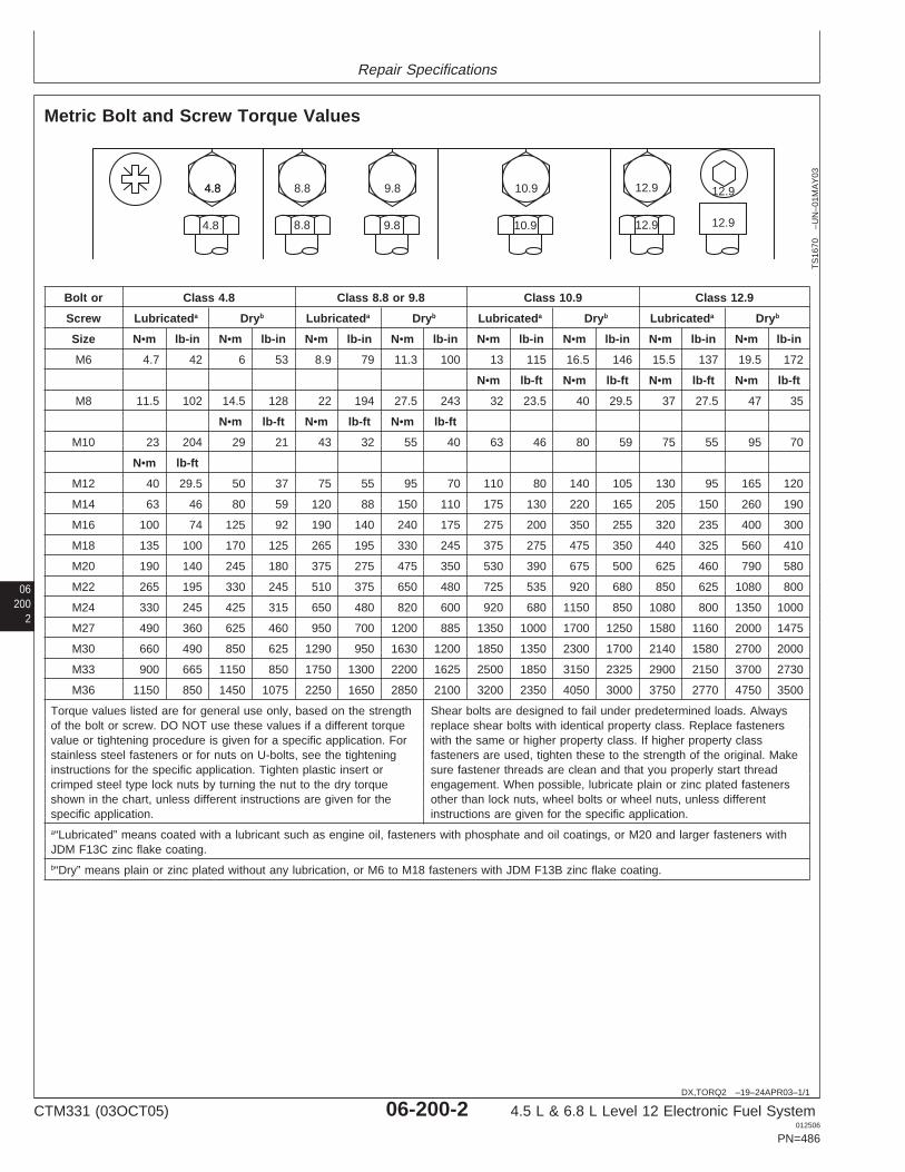
Repair Specifications
06200
2
DX,TORQ2 –19–24APR03–1/1
Metric Bolt and Screw Torque Values
4.84.8 8.8 9.8 10.9 12.9 12.9
12.912.910.99.88.84.8
TS
1670
–UN
–01M
AY
03
Bolt or Class 4.8 Class 8.8 or 9.8 Class 10.9 Class 12.9
Screw Lubricateda Dryb Lubricateda Dryb Lubricateda Dryb Lubricateda Dryb
Size N•m lb-in N•m lb-in N•m lb-in N•m lb-in N•m lb-in N•m lb-in N•m lb-in N•m lb-in
M6 4.7 42 6 53 8.9 79 11.3 100 13 115 16.5 146 15.5 137 19.5 172
N•m lb-ft N•m lb-ft N•m lb-ft N•m lb-ft
M8 11.5 102 14.5 128 22 194 27.5 243 32 23.5 40 29.5 37 27.5 47 35
N•m lb-ft N•m lb-ft N•m lb-ft
M10 23 204 29 21 43 32 55 40 63 46 80 59 75 55 95 70
N•m lb-ft
M12 40 29.5 50 37 75 55 95 70 110 80 140 105 130 95 165 120
M14 63 46 80 59 120 88 150 110 175 130 220 165 205 150 260 190
M16 100 74 125 92 190 140 240 175 275 200 350 255 320 235 400 300
M18 135 100 170 125 265 195 330 245 375 275 475 350 440 325 560 410
M20 190 140 245 180 375 275 475 350 530 390 675 500 625 460 790 580
M22 265 195 330 245 510 375 650 480 725 535 920 680 850 625 1080 800
M24 330 245 425 315 650 480 820 600 920 680 1150 850 1080 800 1350 1000
M27 490 360 625 460 950 700 1200 885 1350 1000 1700 1250 1580 1160 2000 1475
M30 660 490 850 625 1290 950 1630 1200 1850 1350 2300 1700 2140 1580 2700 2000
M33 900 665 1150 850 1750 1300 2200 1625 2500 1850 3150 2325 2900 2150 3700 2730
M36 1150 850 1450 1075 2250 1650 2850 2100 3200 2350 4050 3000 3750 2770 4750 3500
Torque values listed are for general use only, based on the strength Shear bolts are designed to fail under predetermined loads. Alwaysof the bolt or screw. DO NOT use these values if a different torque replace shear bolts with identical property class. Replace fastenersvalue or tightening procedure is given for a specific application. For with the same or higher property class. If higher property classstainless steel fasteners or for nuts on U-bolts, see the tightening fasteners are used, tighten these to the strength of the original. Makeinstructions for the specific application. Tighten plastic insert or sure fastener threads are clean and that you properly start threadcrimped steel type lock nuts by turning the nut to the dry torque engagement. When possible, lubricate plain or zinc plated fastenersshown in the chart, unless different instructions are given for the other than lock nuts, wheel bolts or wheel nuts, unless differentspecific application. instructions are given for the specific application.a“Lubricated” means coated with a lubricant such as engine oil, fasteners with phosphate and oil coatings, or M20 and larger fasteners withJDM F13C zinc flake coating.b“Dry” means plain or zinc plated without any lubrication, or M6 to M18 fasteners with JDM F13B zinc flake coating.
CTM331 (03OCT05) 06-200-2 4.5 L & 6.8 L Level 12 Electronic Fuel System012506
PN=486
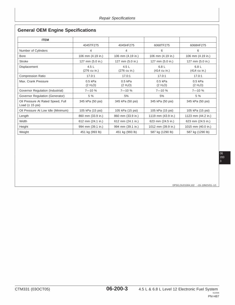
Repair Specifications
062003
DPSG,OUO1004,102 –19–19NOV01–1/1
General OEM Engine Specifications
ITEM
4045TF275 4045HF275 6068TF275 6068HF275
Number of Cylinders 4 4 6 6
Bore 106 mm (4.19 in.) 106 mm (4.19 in.) 106 mm (4.19 in.) 106 mm (4.19 in.)
Stroke 127 mm (5.0 in.) 127 mm (5.0 in.) 127 mm (5.0 in.) 127 mm (5.0 in.)
Displacement 4.5 L 4.5 L 6.8 L 6.8 L(276 cu in.) (276 cu in.) (414 cu in.) (414 cu in.)
Compression Ratio 17.0:1 17.0:1 17.0:1 17.0:1
Max. Crank Pressure 0.5 kPa 0.5 kPa 0.5 kPa 0.5 kPa(2 H2O) (2 H2O) (2 H2O) (2 H2O)
Governor Regulation (Industrial) 7—10 % 7—10 % 7—10 % 7—10 %
Governor Regulation (Generator) 5 % 5% 5% 5 %
Oil Pressure At Rated Speed, Full 345 kPa (50 psi) 345 kPa (50 psi) 345 kPa (50 psi) 345 kPa (50 psi)Load (± 15 psi)
Oil Pressure At Low Idle (Minimum) 105 kPa (15 psi) 105 kPa (15 psi) 105 kPa (15 psi) 105 kPa (15 psi)
Length 860 mm (33.9 in.) 860 mm (33.9 in.) 1119 mm (43.9 in.) 1123 mm (44.2 in.)
Width 612 mm (24.1 in.) 612 mm (24.1 in.) 623 mm (24.5 in.) 623 mm (24.5 in.)
Height 994 mm (39.1 in.) 994 mm (39.1 in.) 1012 mm (39.9 in.) 1015 mm (40.0 in.)
Weight 451 kg (993 lb) 451 kg (993 lb) 587 kg (1290 lb) 587 kg (1290 lb)
CTM331 (03OCT05) 06-200-3 4.5 L & 6.8 L Level 12 Electronic Fuel System012506
PN=487
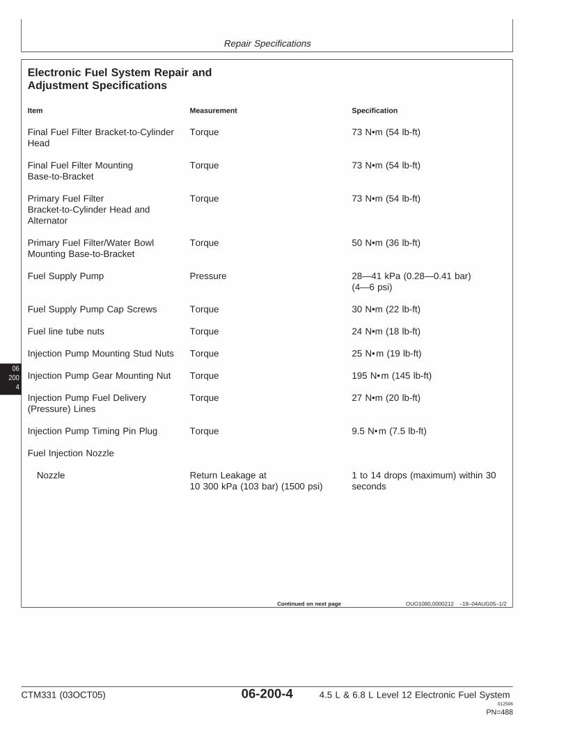
Repair Specifications
06200
4
OUO1080,0000212 –19–04AUG05–1/2
Electronic Fuel System Repair andAdjustment Specifications
Item Measurement Specification
Final Fuel Filter Bracket-to-Cylinder Torque 73 N•m (54 lb-ft)Head
Final Fuel Filter Mounting Torque 73 N•m (54 lb-ft)Base-to-Bracket
Primary Fuel Filter Torque 73 N•m (54 lb-ft)Bracket-to-Cylinder Head andAlternator
Primary Fuel Filter/Water Bowl Torque 50 N•m (36 lb-ft)Mounting Base-to-Bracket
Fuel Supply Pump Pressure 28—41 kPa (0.28—0.41 bar)(4—6 psi)
Fuel Supply Pump Cap Screws Torque 30 N•m (22 lb-ft)
Fuel line tube nuts Torque 24 N•m (18 lb-ft)
Injection Pump Mounting Stud Nuts Torque 25 N•m (19 lb-ft)
Injection Pump Gear Mounting Nut Torque 195 N•m (145 lb-ft)
Injection Pump Fuel Delivery Torque 27 N•m (20 lb-ft)(Pressure) Lines
Injection Pump Timing Pin Plug Torque 9.5 N•m (7.5 lb-ft)
Fuel Injection Nozzle
Nozzle Return Leakage at 1 to 14 drops (maximum) within 3010 300 kPa (103 bar) (1500 psi) seconds
Continued on next page
CTM331 (03OCT05) 06-200-4 4.5 L & 6.8 L Level 12 Electronic Fuel System012506
PN=488
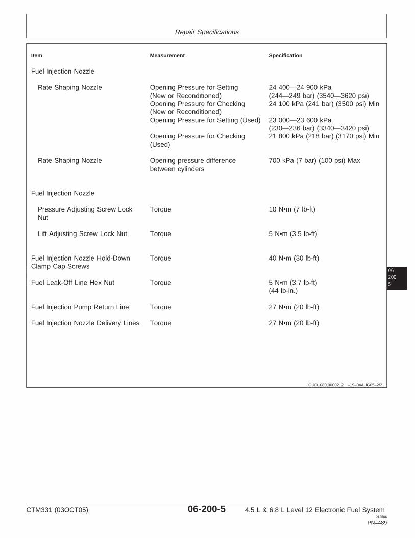
Repair Specifications
062005
OUO1080,0000212 –19–04AUG05–2/2
Item Measurement Specification
Fuel Injection Nozzle
Rate Shaping Nozzle Opening Pressure for Setting 24 400—24 900 kPa(New or Reconditioned) (244—249 bar) (3540—3620 psi)Opening Pressure for Checking 24 100 kPa (241 bar) (3500 psi) Min(New or Reconditioned)Opening Pressure for Setting (Used) 23 000—23 600 kPa
(230—236 bar) (3340—3420 psi)Opening Pressure for Checking 21 800 kPa (218 bar) (3170 psi) Min(Used)
Rate Shaping Nozzle Opening pressure difference 700 kPa (7 bar) (100 psi) Maxbetween cylinders
Fuel Injection Nozzle
Pressure Adjusting Screw Lock Torque 10 N•m (7 lb-ft)Nut
Lift Adjusting Screw Lock Nut Torque 5 N•m (3.5 lb-ft)
Fuel Injection Nozzle Hold-Down Torque 40 N•m (30 lb-ft)Clamp Cap Screws
Fuel Leak-Off Line Hex Nut Torque 5 N•m (3.7 lb-ft)(44 lb-in.)
Fuel Injection Pump Return Line Torque 27 N•m (20 lb-ft)
Fuel Injection Nozzle Delivery Lines Torque 27 N•m (20 lb-ft)
CTM331 (03OCT05) 06-200-5 4.5 L & 6.8 L Level 12 Electronic Fuel System012506
PN=489
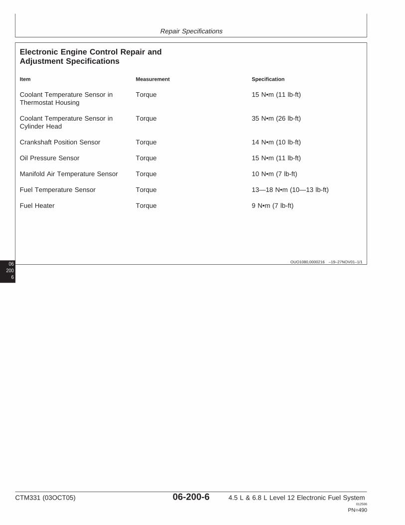
Repair Specifications
06 OUO1080,0000216 –19–27NOV01–1/1
Electronic Engine Control Repair andAdjustment Specifications
Item Measurement Specification
Coolant Temperature Sensor in Torque 15 N•m (11 lb-ft)Thermostat Housing
Coolant Temperature Sensor in Torque 35 N•m (26 lb-ft)Cylinder Head
Crankshaft Position Sensor Torque 14 N•m (10 lb-ft)
Oil Pressure Sensor Torque 15 N•m (11 lb-ft)
Manifold Air Temperature Sensor Torque 10 N•m (7 lb-ft)
Fuel Temperature Sensor Torque 13—18 N•m (10—13 lb-ft)
Fuel Heater Torque 9 N•m (7 lb-ft)
2006
CTM331 (03OCT05) 06-200-6 4.5 L & 6.8 L Level 12 Electronic Fuel System012506
PN=490
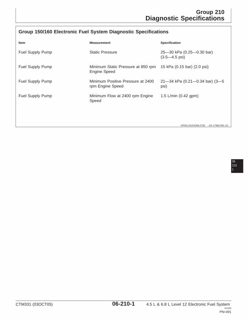
Group 210Diagnostic Specifications
DPSG,OUO1004,2762 –19–17MAY00–1/1
Group 150/160 Electronic Fuel System Diagnostic Specifications
Item Measurement Specification
Fuel Supply Pump Static Pressure 25—30 kPa (0.25—0.30 bar)(3.5—4.5 psi)
Fuel Supply Pump Minimum Static Pressure at 850 rpm 15 kPa (0.15 bar) (2.0 psi)Engine Speed
Fuel Supply Pump Minimum Positive Pressure at 2400 21—34 kPa (0.21—0.34 bar) (3—5rpm Engine Speed psi)
Fuel Supply Pump Minimum Flow at 2400 rpm Engine 1.5 L/min (0.42 gpm)Speed
062101
CTM331 (03OCT05) 06-210-1 4.5 L & 6.8 L Level 12 Electronic Fuel System012506
PN=491
Diagnostic Specifications
06210
2
CTM331 (03OCT05) 06-210-2 4.5 L & 6.8 L Level 12 Electronic Fuel System012506
PN=492
Diagnostic Specifications
062103
RG40854,0000128 –19–29JAN02–1/2
Application Specifications
Below is an overview of the specfications listed forapplications in the next few pages.
• Backhoes– Sensor Specifications - See BACKHOES -
SENSOR SPECIFICATIONS later in this Group.– Torque Curve Selection - See BACKHOES -
TORQUE CURVE SELECTION later in thisGroup.
– Governor Mode Selection - See BACKHOES -GOVERNOR MODE SELECTION later in thisGroup.
– ECU Terminal Identification - See BACKHOES -ECU TERMINAL IDENTIFICATION later in thisGroup.
– Vehicle Wiring - See Vehicle manual.• Crawlers
– Sensor Specifications - See CRAWLERS -SENSOR SPECIFICATIONS later in this Group.
– Torque Curve Selection - See CRAWLERS -TORQUE CURVE SELECTION later in thisGroup.
– Governor Mode Selection - See CRAWLERS -GOVERNOR MODE SELECTION later in thisGroup.
– ECU Terminal Identification - See CRAWLERS -ECU TERMINAL IDENTIFICATION later in thisGroup.
– Vehicle Wiring - See Vehicle manual.• Excavators
– Sensor Specifications - See EXCAVATORS -SENSOR SPECIFICATIONS later in this Group.
– Torque Curve Selection - See EXCAVATORS -TORQUE CURVE SELECTION later in thisGroup.
– Governor Mode Selection - See EXCAVATORS -GOVERNOR MODE SELECTION later in thisGroup.
– ECU Terminal Identification - See EXCAVATORS- ECU TERMINAL IDENTIFICATION later in thisGroup.
– Vehicle Wiring - See Vehicle manual.
• Forwarders– Sensor Specifications - See FORWARDERS -
SENSOR SPECIFICATIONS later in this Group.– Torque Curve Selection - See FORWARDERS -
TORQUE CURVE SELECTION later in thisGroup.
– Governor Mode Selection - See FORWARDERS -GOVERNOR MODE SELECTION later in thisGroup.
– ECU Terminal Identification - See FORWARDERS- ECU TERMINAL IDENTIFICATION later in thisGroup.
– Vehicle Wiring - See Vehicle manual.• Harvesters
– Sensor Specifications - See HARVESTERS -SENSOR SPECIFICATIONS later in this Group.
– Torque Curve Selection - See HARVESTERS -TORQUE CURVE SELECTION later in thisGroup.
– Governor Mode Selection - See HARVESTERS -GOVERNOR MODE SELECTION later in thisGroup.
– ECU Terminal Identification - See HARVESTERS- ECU TERMINAL IDENTIFICATION later in thisGroup.
– Vehicle Wiring - See Vehicle manual.• OEM Engines
– Sensor Specifications - See OEM ENGINES -SENSOR SPECIFICATIONS later in this Group.
– Torque Curve Selection - See OEM ENGINES -TORQUE CURVE SELECTION later in thisGroup.
– Governor Mode Selection - See OEM ENGINES -GOVERNOR MODE SELECTION later in thisGroup.
– ECU Terminal Identification - See OEM ENGINES- ECU TERMINAL IDENTIFICATION later in thisGroup.
– Electronic Control System Wiring Diagram forBase ECUs - See OEM ENGINES -ELECTRONIC CONTROL SYSTEM WIRINGDIAGRAM BASE ECUS later in this Group.
CTM331 (03OCT05) 06-210-3 4.5 L & 6.8 L Level 12 Electronic Fuel System012506
PN=493
Continued on next page
Diagnostic Specifications
06210
4
RG40854,0000128 –19–29JAN02–2/2
– Electronic Control System Wiring Diagram forEarly Extended ECUs - See OEM ENGINES -ELECTRONIC CONTROL SYSTEM WIRINGDIAGRAM EXTENDED ECUS (EARLY) later inthis Group.
– Electronic Control System Wiring Diagram forLater Extended ECUs - See OEM ENGINES -ELECTRONIC CONTROL SYSTEM WIRINGDIAGRAM EXTENDED ECUS (LATER) later inthis Group.
– 4.5L & 6.8L OEM Application InstrumentPanel/Engine Start Components Electrical WiringDiagram - See OEM ENGINES - 4.5L & 6.8LOEM APPLICATION INSTRUMENTPANEL/ENGINE START COMPONENTSELECTRICAL WIRING DIAGRAM later in thisGroup.
• Skidders– Sensor Specifications - See SKIDDERS -
SENSOR SPECIFICATIONS later in this Group.– Torque Curve Selection - See SKIDDERS -
TORQUE CURVE SELECTION later in thisGroup.
– Governor Mode Selection - See SKIDDERS -GOVERNOR MODE SELECTION later in thisGroup.
– ECU Terminal Identification - See SKIDDERS -ECU TERMINAL IDENTIFICATION later in thisGroup.
– Vehicle Wiring - See Vehicle manual.• Telehandlers
– Sensor Specifications - See TELEHANDLERS -SENSOR SPECIFICATIONS later in this Group.
– Torque Curve Selection - See TELEHANDLERS -TORQUE CURVE SELECTION later in thisGroup.
– Governor Mode Selection - See TELEHANDLERS- GOVERNOR MODE SELECTION later in thisGroup.
– ECU Terminal Identification - SeeTELEHANDLERS - ECU TERMINALIDENTIFICATION later in this Group.
– Vehicle Wiring - See Vehicle manual.• Tractors
– Sensor Specifications - See TRACTORS -SENSOR SPECIFICATIONS later in this Group.
– Torque Curve Selection - See TRACTORS -TORQUE CURVE SELECTION later in thisGroup.
– Governor Mode Selection - See TRACTORS -GOVERNOR MODE SELECTION later in thisGroup.
– ECU Terminal Identification - See TRACTORS -ECU TERMINAL IDENTIFICATION later in thisGroup.
– Vehicle Wiring - See Vehicle manual.
CTM331 (03OCT05) 06-210-4 4.5 L & 6.8 L Level 12 Electronic Fuel System012506
PN=494
Diagnostic Specifications
062105
CTM331 (03OCT05) 06-210-5 4.5 L & 6.8 L Level 12 Electronic Fuel System012506
PN=495
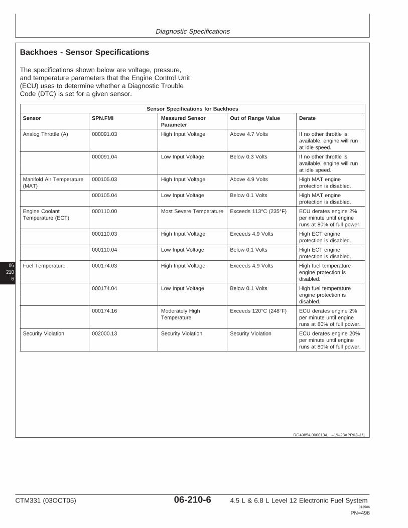
Diagnostic Specifications
06210
6
RG40854,000013A –19–23APR02–1/1
Backhoes - Sensor Specifications
The specifications shown below are voltage, pressure,and temperature parameters that the Engine Control Unit(ECU) uses to determine whether a Diagnostic TroubleCode (DTC) is set for a given sensor.
Sensor Specifications for Backhoes
Sensor SPN.FMI Measured Sensor Out of Range Value DerateParameter
Analog Throttle (A) 000091.03 High Input Voltage Above 4.7 Volts If no other throttle isavailable, engine will runat idle speed.
000091.04 Low Input Voltage Below 0.3 Volts If no other throttle isavailable, engine will runat idle speed.
Manifold Air Temperature 000105.03 High Input Voltage Above 4.9 Volts High MAT engine(MAT) protection is disabled.
000105.04 Low Input Voltage Below 0.1 Volts High MAT engineprotection is disabled.
Engine Coolant 000110.00 Most Severe Temperature Exceeds 113°C (235°F) ECU derates engine 2%Temperature (ECT) per minute until engine
runs at 80% of full power.
000110.03 High Input Voltage Exceeds 4.9 Volts High ECT engineprotection is disabled.
000110.04 Low Input Voltage Below 0.1 Volts High ECT engineprotection is disabled.
Fuel Temperature 000174.03 High Input Voltage Exceeds 4.9 Volts High fuel temperatureengine protection isdisabled.
000174.04 Low Input Voltage Below 0.1 Volts High fuel temperatureengine protection isdisabled.
000174.16 Moderately High Exceeds 120°C (248°F) ECU derates engine 2%Temperature per minute until engine
runs at 80% of full power.
Security Violation 002000.13 Security Violation Security Violation ECU derates engine 20%per minute until engineruns at 80% of full power.
CTM331 (03OCT05) 06-210-6 4.5 L & 6.8 L Level 12 Electronic Fuel System012506
PN=496
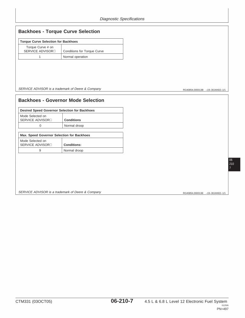
Diagnostic Specifications
RG40854,000013B –19–30JAN02–1/1
Backhoes - Torque Curve Selection
Torque Curve Selection for Backhoes
Torque Curve # onSERVICE ADVISOR Conditions for Torque Curve
1 Normal operation
SERVICE ADVISOR is a trademark of Deere & Company
062107
RG40854,000013E –19–30JAN02–1/1
Backhoes - Governor Mode Selection
Desired Speed Governor Selection for Backhoes
Mode Selected onSERVICE ADVISOR Conditions
0 Normal droop
Max. Speed Governor Selection for Backhoes
Mode Selected onSERVICE ADVISOR Conditions:
9 Normal droop
SERVICE ADVISOR is a trademark of Deere & Company
CTM331 (03OCT05) 06-210-7 4.5 L & 6.8 L Level 12 Electronic Fuel System012506
PN=497

Diagnostic Specifications
06210
8
RG40854,000013F –19–30JAN02–1/1
Backhoes - ECU Terminal Identification
ECU Terminal Function ECU Terminal # Sensor Connector Terminal #
Switched Battery A2 N/Aa
Unswitched Battery K1 N/Aa
System Ground J2 N/Aa
CAN High G1 N/Aa
CAN Low F1 N/Aa
5V Sensor Supply E2 Changes with each sensor
Sensor Ground D3 Changes with each sensor
Analog Throttle (A) Input B3 B
Crank Position Input B2 A
Crank Position Return D2 B
Pump Solenoid Return A3 B
Pump Solenoid Supply K2 A
Fuel Temperature Input C3 A
Engine Coolant Temperature Input B1 A
Manifold Air Temperature Input D1 AaN/A = Not Applicable
CTM331 (03OCT05) 06-210-8 4.5 L & 6.8 L Level 12 Electronic Fuel System012506
PN=498

Diagnostic Specifications
062109
CTM331 (03OCT05) 06-210-9 4.5 L & 6.8 L Level 12 Electronic Fuel System012506
PN=499
Diagnostic Specifications
RG40854,0000132 –19–23APR02–1/2
Crawlers - Sensor Specifications
The specifications shown below are voltage, pressure,and temperature parameters that the Engine Control Unit(ECU) uses to determine whether a Diagnostic TroubleCode (DTC) is set for a given sensor.
Continued on next page
06210
10
CTM331 (03OCT05) 06-210-10 4.5 L & 6.8 L Level 12 Electronic Fuel System012506
PN=500
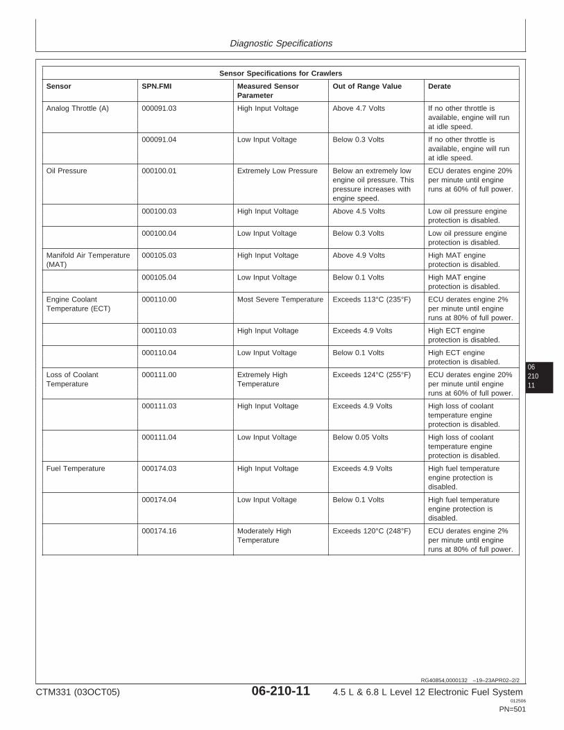
Diagnostic Specifications
0621011
RG40854,0000132 –19–23APR02–2/2
Sensor Specifications for Crawlers
Sensor SPN.FMI Measured Sensor Out of Range Value DerateParameter
Analog Throttle (A) 000091.03 High Input Voltage Above 4.7 Volts If no other throttle isavailable, engine will runat idle speed.
000091.04 Low Input Voltage Below 0.3 Volts If no other throttle isavailable, engine will runat idle speed.
Oil Pressure 000100.01 Extremely Low Pressure Below an extremely low ECU derates engine 20%engine oil pressure. This per minute until enginepressure increases with runs at 60% of full power.engine speed.
000100.03 High Input Voltage Above 4.5 Volts Low oil pressure engineprotection is disabled.
000100.04 Low Input Voltage Below 0.3 Volts Low oil pressure engineprotection is disabled.
Manifold Air Temperature 000105.03 High Input Voltage Above 4.9 Volts High MAT engine(MAT) protection is disabled.
000105.04 Low Input Voltage Below 0.1 Volts High MAT engineprotection is disabled.
Engine Coolant 000110.00 Most Severe Temperature Exceeds 113°C (235°F) ECU derates engine 2%Temperature (ECT) per minute until engine
runs at 80% of full power.
000110.03 High Input Voltage Exceeds 4.9 Volts High ECT engineprotection is disabled.
000110.04 Low Input Voltage Below 0.1 Volts High ECT engineprotection is disabled.
Loss of Coolant 000111.00 Extremely High Exceeds 124°C (255°F) ECU derates engine 20%Temperature Temperature per minute until engine
runs at 60% of full power.
000111.03 High Input Voltage Exceeds 4.9 Volts High loss of coolanttemperature engineprotection is disabled.
000111.04 Low Input Voltage Below 0.05 Volts High loss of coolanttemperature engineprotection is disabled.
Fuel Temperature 000174.03 High Input Voltage Exceeds 4.9 Volts High fuel temperatureengine protection isdisabled.
000174.04 Low Input Voltage Below 0.1 Volts High fuel temperatureengine protection isdisabled.
000174.16 Moderately High Exceeds 120°C (248°F) ECU derates engine 2%Temperature per minute until engine
runs at 80% of full power.
CTM331 (03OCT05) 06-210-11 4.5 L & 6.8 L Level 12 Electronic Fuel System012506
PN=501

Diagnostic Specifications
RG40854,0000135 –19–30JAN02–1/1
Crawlers - Torque Curve Selection
Torque Curve Selection for Crawlers
Torque Curve # onSERVICE ADVISOR Conditions for Torque Curve
1 Normal operation
SERVICE ADVISOR is a trademark of Deere & Company
06210
12
RG40854,0000134 –19–30JAN02–1/1
Crawlers - Governor Mode Selection
Desired Speed Governor Selection for Crawlers
Mode Selected onSERVICE ADVISOR Conditions
0 Normal droop
Max. Speed Governor Selection for Excavators
Mode Selected onSERVICE ADVISOR Conditions:
9 Normal droop
SERVICE ADVISOR is a trademark of Deere & Company
CTM331 (03OCT05) 06-210-12 4.5 L & 6.8 L Level 12 Electronic Fuel System012506
PN=502
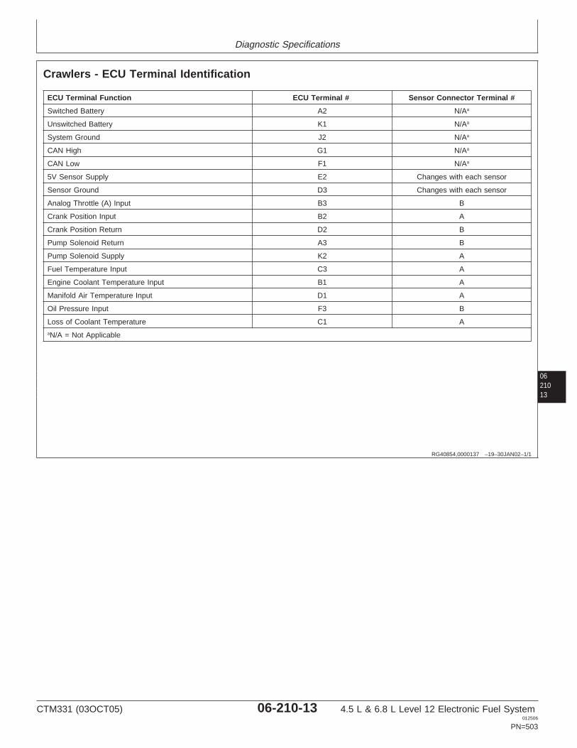
Diagnostic Specifications
0621013
RG40854,0000137 –19–30JAN02–1/1
Crawlers - ECU Terminal Identification
ECU Terminal Function ECU Terminal # Sensor Connector Terminal #
Switched Battery A2 N/Aa
Unswitched Battery K1 N/Aa
System Ground J2 N/Aa
CAN High G1 N/Aa
CAN Low F1 N/Aa
5V Sensor Supply E2 Changes with each sensor
Sensor Ground D3 Changes with each sensor
Analog Throttle (A) Input B3 B
Crank Position Input B2 A
Crank Position Return D2 B
Pump Solenoid Return A3 B
Pump Solenoid Supply K2 A
Fuel Temperature Input C3 A
Engine Coolant Temperature Input B1 A
Manifold Air Temperature Input D1 A
Oil Pressure Input F3 B
Loss of Coolant Temperature C1 AaN/A = Not Applicable
CTM331 (03OCT05) 06-210-13 4.5 L & 6.8 L Level 12 Electronic Fuel System012506
PN=503
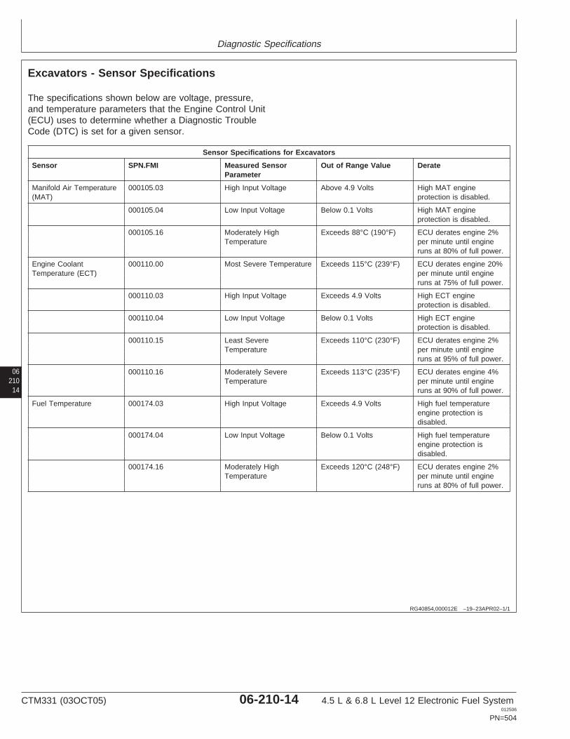
Diagnostic Specifications
06210
14
RG40854,000012E –19–23APR02–1/1
Excavators - Sensor Specifications
The specifications shown below are voltage, pressure,and temperature parameters that the Engine Control Unit(ECU) uses to determine whether a Diagnostic TroubleCode (DTC) is set for a given sensor.
Sensor Specifications for Excavators
Sensor SPN.FMI Measured Sensor Out of Range Value DerateParameter
Manifold Air Temperature 000105.03 High Input Voltage Above 4.9 Volts High MAT engine(MAT) protection is disabled.
000105.04 Low Input Voltage Below 0.1 Volts High MAT engineprotection is disabled.
000105.16 Moderately High Exceeds 88°C (190°F) ECU derates engine 2%Temperature per minute until engine
runs at 80% of full power.
Engine Coolant 000110.00 Most Severe Temperature Exceeds 115°C (239°F) ECU derates engine 20%Temperature (ECT) per minute until engine
runs at 75% of full power.
000110.03 High Input Voltage Exceeds 4.9 Volts High ECT engineprotection is disabled.
000110.04 Low Input Voltage Below 0.1 Volts High ECT engineprotection is disabled.
000110.15 Least Severe Exceeds 110°C (230°F) ECU derates engine 2%Temperature per minute until engine
runs at 95% of full power.
000110.16 Moderately Severe Exceeds 113°C (235°F) ECU derates engine 4%Temperature per minute until engine
runs at 90% of full power.
Fuel Temperature 000174.03 High Input Voltage Exceeds 4.9 Volts High fuel temperatureengine protection isdisabled.
000174.04 Low Input Voltage Below 0.1 Volts High fuel temperatureengine protection isdisabled.
000174.16 Moderately High Exceeds 120°C (248°F) ECU derates engine 2%Temperature per minute until engine
runs at 80% of full power.
CTM331 (03OCT05) 06-210-14 4.5 L & 6.8 L Level 12 Electronic Fuel System012506
PN=504
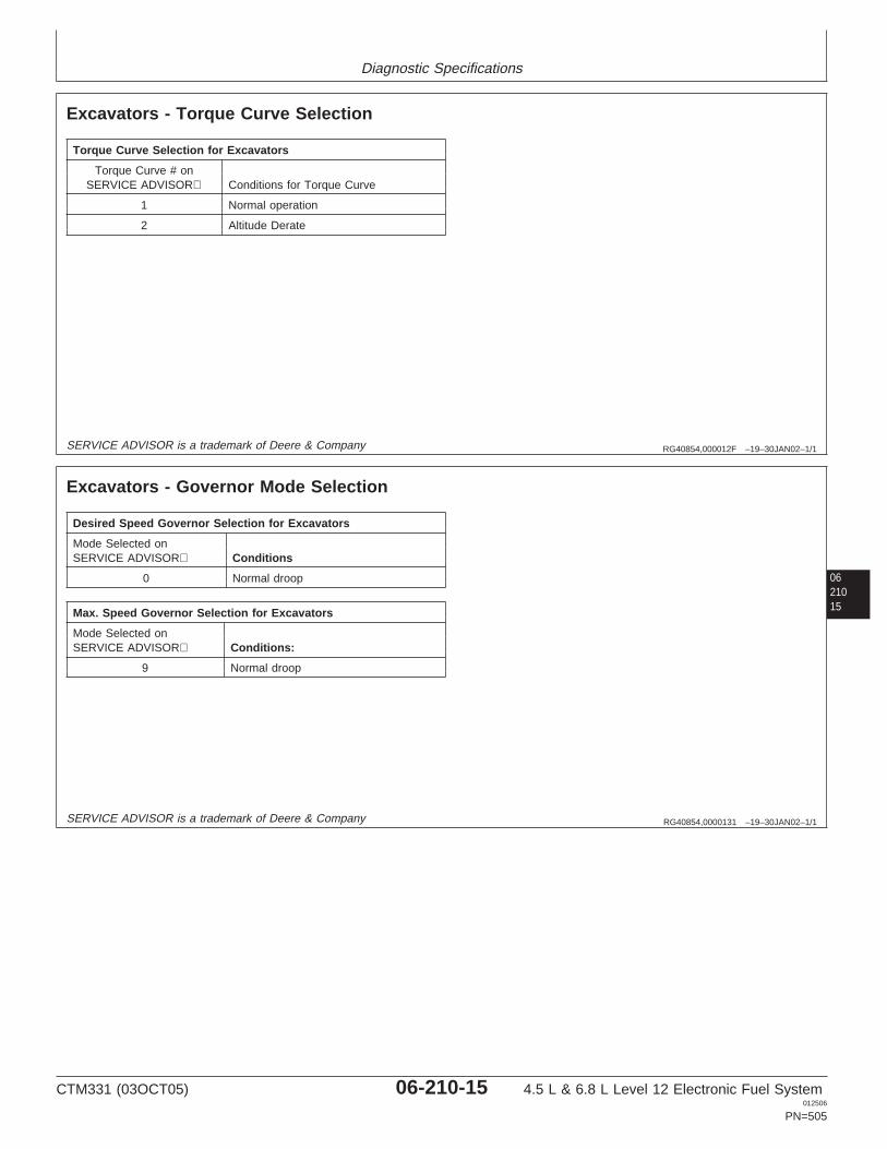
Diagnostic Specifications
RG40854,000012F –19–30JAN02–1/1
Excavators - Torque Curve Selection
Torque Curve Selection for Excavators
Torque Curve # onSERVICE ADVISOR Conditions for Torque Curve
1 Normal operation
2 Altitude Derate
0621015
SERVICE ADVISOR is a trademark of Deere & Company
RG40854,0000131 –19–30JAN02–1/1
Excavators - Governor Mode Selection
Desired Speed Governor Selection for Excavators
Mode Selected onSERVICE ADVISOR Conditions
0 Normal droop
Max. Speed Governor Selection for Excavators
Mode Selected onSERVICE ADVISOR Conditions:
9 Normal droop
SERVICE ADVISOR is a trademark of Deere & Company
CTM331 (03OCT05) 06-210-15 4.5 L & 6.8 L Level 12 Electronic Fuel System012506
PN=505
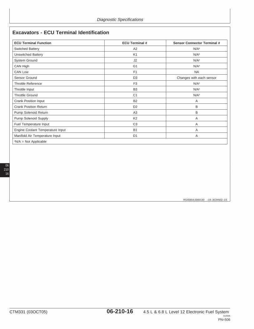
Diagnostic Specifications
06210
16
RG40854,0000130 –19–30JAN02–1/1
Excavators - ECU Terminal Identification
ECU Terminal Function ECU Terminal # Sensor Connector Terminal #
Switched Battery A2 N/Aa
Unswitched Battery K1 N/Aa
System Ground J2 N/Aa
CAN High G1 N/Aa
CAN Low F1 NA
Sensor Ground D3 Changes with each sensor
Throttle Reference F3 N/Aa
Throttle Input B3 N/Aa
Throttle Ground C1 N/Aa
Crank Position Input B2 A
Crank Position Return D2 B
Pump Solenoid Return A3 B
Pump Solenoid Supply K2 A
Fuel Temperature Input C3 A
Engine Coolant Temperature Input B1 A
Manifold Air Temperature Input D1 AaN/A = Not Applicable
CTM331 (03OCT05) 06-210-16 4.5 L & 6.8 L Level 12 Electronic Fuel System012506
PN=506

Diagnostic Specifications
0621017
CTM331 (03OCT05) 06-210-17 4.5 L & 6.8 L Level 12 Electronic Fuel System012506
PN=507
Diagnostic Specifications
RG40854,0000158 –19–23APR02–1/3
Forwarders - Sensor Specifications
The specifications shown below are voltage, pressure,and temperature parameters that the Engine Control Unit(ECU) uses to determine whether a Diagnostic TroubleCode (DTC) is set for a given sensor.
Continued on next page
06210
18
CTM331 (03OCT05) 06-210-18 4.5 L & 6.8 L Level 12 Electronic Fuel System012506
PN=508
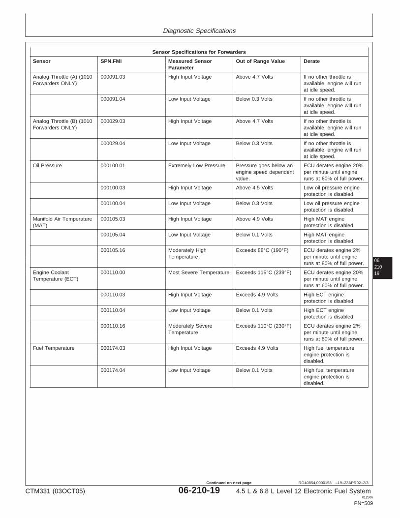
Diagnostic Specifications
0621019
RG40854,0000158 –19–23APR02–2/3
Sensor Specifications for Forwarders
Sensor SPN.FMI Measured Sensor Out of Range Value DerateParameter
Analog Throttle (A) (1010 000091.03 High Input Voltage Above 4.7 Volts If no other throttle isForwarders ONLY) available, engine will run
at idle speed.
000091.04 Low Input Voltage Below 0.3 Volts If no other throttle isavailable, engine will runat idle speed.
Analog Throttle (B) (1010 000029.03 High Input Voltage Above 4.7 Volts If no other throttle isForwarders ONLY) available, engine will run
at idle speed.
000029.04 Low Input Voltage Below 0.3 Volts If no other throttle isavailable, engine will runat idle speed.
Oil Pressure 000100.01 Extremely Low Pressure Pressure goes below an ECU derates engine 20%engine speed dependent per minute until enginevalue. runs at 60% of full power.
000100.03 High Input Voltage Above 4.5 Volts Low oil pressure engineprotection is disabled.
000100.04 Low Input Voltage Below 0.3 Volts Low oil pressure engineprotection is disabled.
Manifold Air Temperature 000105.03 High Input Voltage Above 4.9 Volts High MAT engine(MAT) protection is disabled.
000105.04 Low Input Voltage Below 0.1 Volts High MAT engineprotection is disabled.
000105.16 Moderately High Exceeds 88°C (190°F) ECU derates engine 2%Temperature per minute until engine
runs at 80% of full power.
Engine Coolant 000110.00 Most Severe Temperature Exceeds 115°C (239°F) ECU derates engine 20%Temperature (ECT) per minute until engine
runs at 60% of full power.
000110.03 High Input Voltage Exceeds 4.9 Volts High ECT engineprotection is disabled.
000110.04 Low Input Voltage Below 0.1 Volts High ECT engineprotection is disabled.
000110.16 Moderately Severe Exceeds 110°C (230°F) ECU derates engine 2%Temperature per minute until engine
runs at 80% of full power.
Fuel Temperature 000174.03 High Input Voltage Exceeds 4.9 Volts High fuel temperatureengine protection isdisabled.
000174.04 Low Input Voltage Below 0.1 Volts High fuel temperatureengine protection isdisabled.
CTM331 (03OCT05) 06-210-19 4.5 L & 6.8 L Level 12 Electronic Fuel System012506
PN=509
Continued on next page
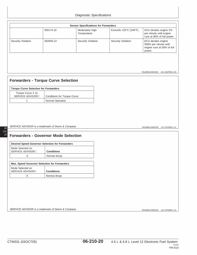
Diagnostic Specifications
RG40854,0000158 –19–23APR02–3/3
Sensor Specifications for Forwarders
000174.16 Moderately High Exceeds 120°C (248°F) ECU derates engine 2%Temperature per minute until engine
runs at 80% of full power.
Security Violation 002000.13 Security Violation Security Violation ECU derates engine500% per minute untilengine runs at 50% of fullpower.
06 RG40854,0000159 –19–21FEB02–1/1
Forwarders - Torque Curve Selection
Torque Curve Selection for Forwarders
Torque Curve # onSERVICE ADVISOR Conditions for Torque Curve
1 Normal Operation
21020
SERVICE ADVISOR is a trademark of Deere & Company
RG40854,000015A –19–21FEB02–1/1
Forwarders - Governor Mode Selection
Desired Speed Governor Selection for Forwarders
Mode Selected onSERVICE ADVISOR Conditions
0 Normal droop
Max. Speed Governor Selection for Forwarders
Mode Selected onSERVICE ADVISOR Conditions:
9 Normal droop
SERVICE ADVISOR is a trademark of Deere & Company
CTM331 (03OCT05) 06-210-20 4.5 L & 6.8 L Level 12 Electronic Fuel System012506
PN=510
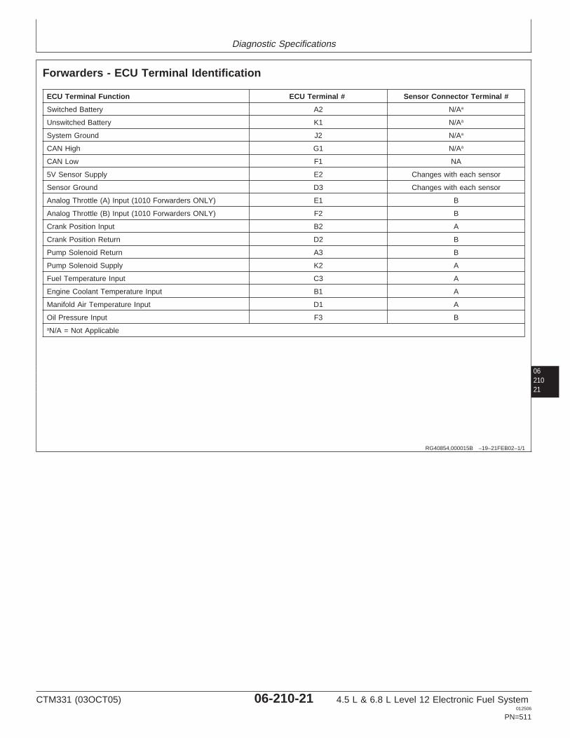
Diagnostic Specifications
0621021
RG40854,000015B –19–21FEB02–1/1
Forwarders - ECU Terminal Identification
ECU Terminal Function ECU Terminal # Sensor Connector Terminal #
Switched Battery A2 N/Aa
Unswitched Battery K1 N/Aa
System Ground J2 N/Aa
CAN High G1 N/Aa
CAN Low F1 NA
5V Sensor Supply E2 Changes with each sensor
Sensor Ground D3 Changes with each sensor
Analog Throttle (A) Input (1010 Forwarders ONLY) E1 B
Analog Throttle (B) Input (1010 Forwarders ONLY) F2 B
Crank Position Input B2 A
Crank Position Return D2 B
Pump Solenoid Return A3 B
Pump Solenoid Supply K2 A
Fuel Temperature Input C3 A
Engine Coolant Temperature Input B1 A
Manifold Air Temperature Input D1 A
Oil Pressure Input F3 BaN/A = Not Applicable
CTM331 (03OCT05) 06-210-21 4.5 L & 6.8 L Level 12 Electronic Fuel System012506
PN=511
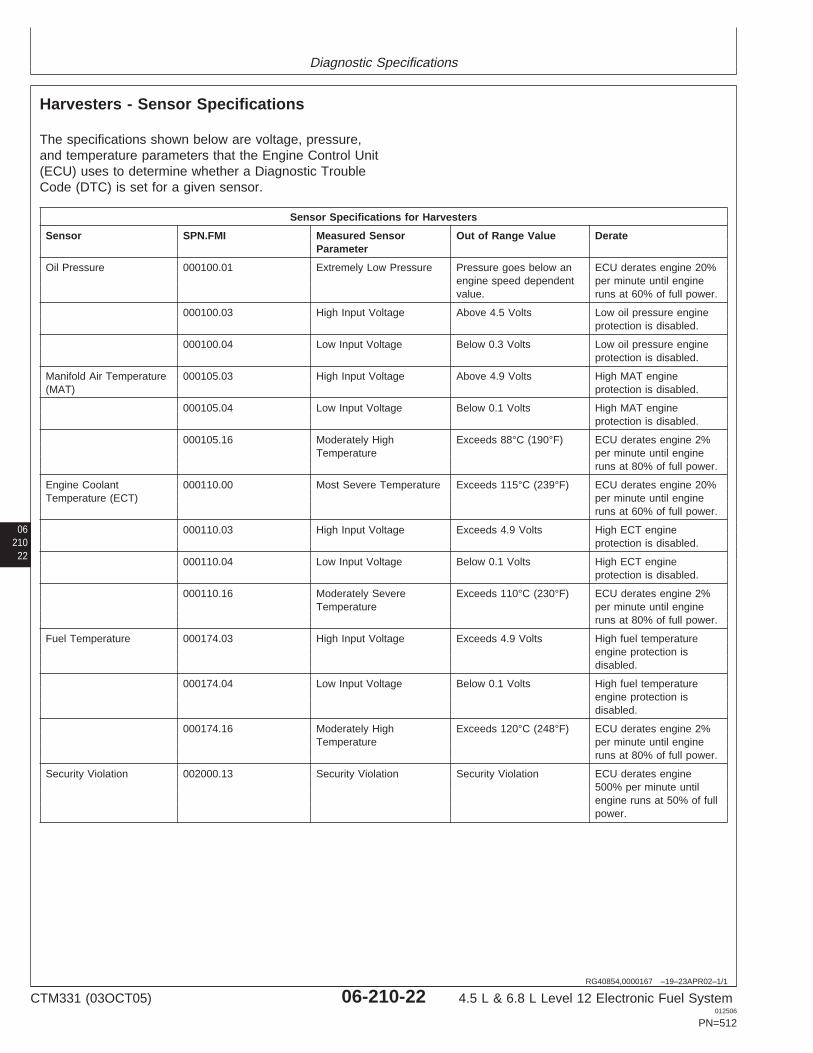
Diagnostic Specifications
06210
22
RG40854,0000167 –19–23APR02–1/1
Harvesters - Sensor Specifications
The specifications shown below are voltage, pressure,and temperature parameters that the Engine Control Unit(ECU) uses to determine whether a Diagnostic TroubleCode (DTC) is set for a given sensor.
Sensor Specifications for Harvesters
Sensor SPN.FMI Measured Sensor Out of Range Value DerateParameter
Oil Pressure 000100.01 Extremely Low Pressure Pressure goes below an ECU derates engine 20%engine speed dependent per minute until enginevalue. runs at 60% of full power.
000100.03 High Input Voltage Above 4.5 Volts Low oil pressure engineprotection is disabled.
000100.04 Low Input Voltage Below 0.3 Volts Low oil pressure engineprotection is disabled.
Manifold Air Temperature 000105.03 High Input Voltage Above 4.9 Volts High MAT engine(MAT) protection is disabled.
000105.04 Low Input Voltage Below 0.1 Volts High MAT engineprotection is disabled.
000105.16 Moderately High Exceeds 88°C (190°F) ECU derates engine 2%Temperature per minute until engine
runs at 80% of full power.
Engine Coolant 000110.00 Most Severe Temperature Exceeds 115°C (239°F) ECU derates engine 20%Temperature (ECT) per minute until engine
runs at 60% of full power.
000110.03 High Input Voltage Exceeds 4.9 Volts High ECT engineprotection is disabled.
000110.04 Low Input Voltage Below 0.1 Volts High ECT engineprotection is disabled.
000110.16 Moderately Severe Exceeds 110°C (230°F) ECU derates engine 2%Temperature per minute until engine
runs at 80% of full power.
Fuel Temperature 000174.03 High Input Voltage Exceeds 4.9 Volts High fuel temperatureengine protection isdisabled.
000174.04 Low Input Voltage Below 0.1 Volts High fuel temperatureengine protection isdisabled.
000174.16 Moderately High Exceeds 120°C (248°F) ECU derates engine 2%Temperature per minute until engine
runs at 80% of full power.
Security Violation 002000.13 Security Violation Security Violation ECU derates engine500% per minute untilengine runs at 50% of fullpower.
CTM331 (03OCT05) 06-210-22 4.5 L & 6.8 L Level 12 Electronic Fuel System012506
PN=512
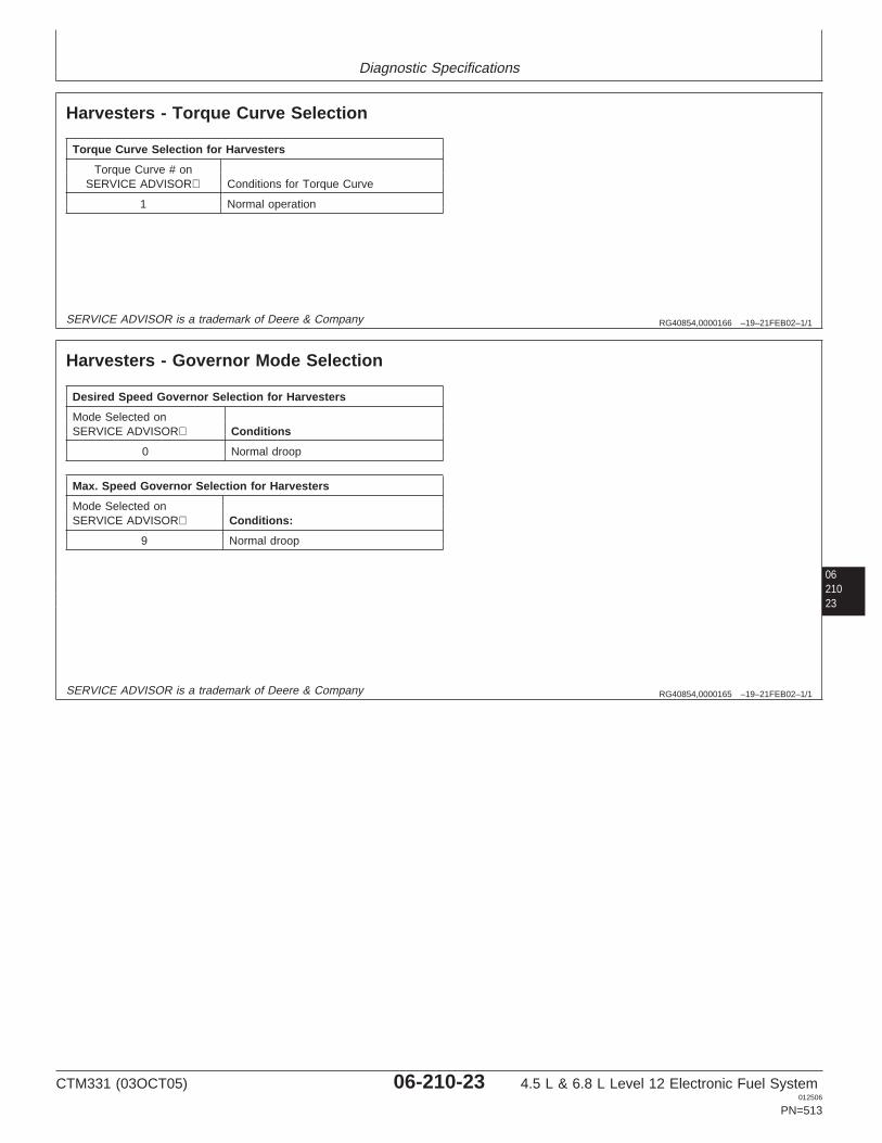
Diagnostic Specifications
RG40854,0000166 –19–21FEB02–1/1
Harvesters - Torque Curve Selection
Torque Curve Selection for Harvesters
Torque Curve # onSERVICE ADVISOR Conditions for Torque Curve
1 Normal operation
SERVICE ADVISOR is a trademark of Deere & Company
0621023
RG40854,0000165 –19–21FEB02–1/1
Harvesters - Governor Mode Selection
Desired Speed Governor Selection for Harvesters
Mode Selected onSERVICE ADVISOR Conditions
0 Normal droop
Max. Speed Governor Selection for Harvesters
Mode Selected onSERVICE ADVISOR Conditions:
9 Normal droop
SERVICE ADVISOR is a trademark of Deere & Company
CTM331 (03OCT05) 06-210-23 4.5 L & 6.8 L Level 12 Electronic Fuel System012506
PN=513

Diagnostic Specifications
06210
24
RG40854,0000164 –19–21FEB02–1/1
Harvesters - ECU Terminal Identification
ECU Terminal Function ECU Terminal # Sensor Connector Terminal #
Switched Battery A2 N/Aa
Unswitched Battery K1 N/Aa
System Ground J2 N/Aa
CAN High G1 N/Aa
CAN Low F1 NA
5V Sensor Supply E2 Changes with each sensor
Sensor Ground D3 Changes with each sensor
Crank Position Input B2 A
Crank Position Return D2 B
Pump Solenoid Return A3 B
Pump Solenoid Supply K2 A
Fuel Temperature Input C3 A
Engine Coolant Temperature Input B1 A
Manifold Air Temperature Input D1 A
Oil Pressure Input F3 BaN/A = Not Applicable
CTM331 (03OCT05) 06-210-24 4.5 L & 6.8 L Level 12 Electronic Fuel System012506
PN=514
Diagnostic Specifications
0621025
CTM331 (03OCT05) 06-210-25 4.5 L & 6.8 L Level 12 Electronic Fuel System012506
PN=515

Diagnostic Specifications
RG40854,0000129 –19–23APR02–1/3
OEM Engines - Sensor Specifications
The specifications shown below are voltage, pressure,and temperature parameters that the Engine Control Unit(ECU) uses to determine whether a Diagnostic TroubleCode (DTC) is set for a given sensor.
Continued on next page
06210
26
CTM331 (03OCT05) 06-210-26 4.5 L & 6.8 L Level 12 Electronic Fuel System012506
PN=516
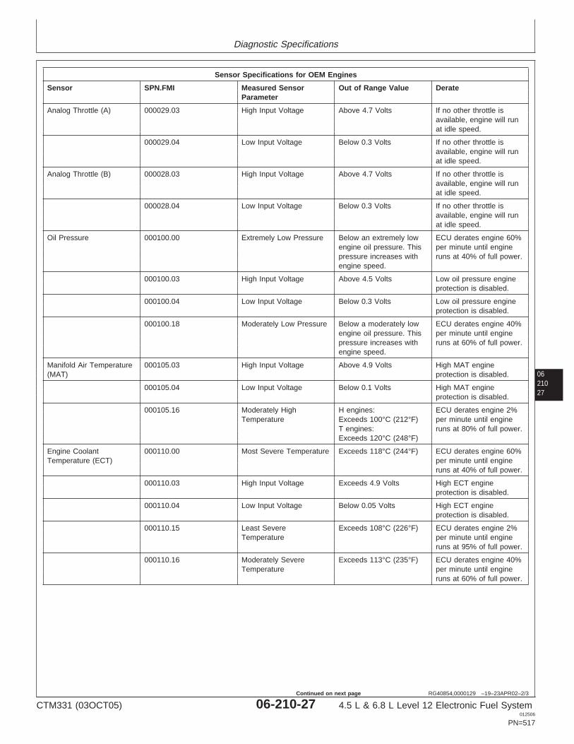
Diagnostic Specifications
0621027
RG40854,0000129 –19–23APR02–2/3
Sensor Specifications for OEM Engines
Sensor SPN.FMI Measured Sensor Out of Range Value DerateParameter
Analog Throttle (A) 000029.03 High Input Voltage Above 4.7 Volts If no other throttle isavailable, engine will runat idle speed.
000029.04 Low Input Voltage Below 0.3 Volts If no other throttle isavailable, engine will runat idle speed.
Analog Throttle (B) 000028.03 High Input Voltage Above 4.7 Volts If no other throttle isavailable, engine will runat idle speed.
000028.04 Low Input Voltage Below 0.3 Volts If no other throttle isavailable, engine will runat idle speed.
Oil Pressure 000100.00 Extremely Low Pressure Below an extremely low ECU derates engine 60%engine oil pressure. This per minute until enginepressure increases with runs at 40% of full power.engine speed.
000100.03 High Input Voltage Above 4.5 Volts Low oil pressure engineprotection is disabled.
000100.04 Low Input Voltage Below 0.3 Volts Low oil pressure engineprotection is disabled.
000100.18 Moderately Low Pressure Below a moderately low ECU derates engine 40%engine oil pressure. This per minute until enginepressure increases with runs at 60% of full power.engine speed.
Manifold Air Temperature 000105.03 High Input Voltage Above 4.9 Volts High MAT engine(MAT) protection is disabled.
000105.04 Low Input Voltage Below 0.1 Volts High MAT engineprotection is disabled.
000105.16 Moderately High H engines: ECU derates engine 2%Temperature Exceeds 100°C (212°F) per minute until engine
T engines: runs at 80% of full power.Exceeds 120°C (248°F)
Engine Coolant 000110.00 Most Severe Temperature Exceeds 118°C (244°F) ECU derates engine 60%Temperature (ECT) per minute until engine
runs at 40% of full power.
000110.03 High Input Voltage Exceeds 4.9 Volts High ECT engineprotection is disabled.
000110.04 Low Input Voltage Below 0.05 Volts High ECT engineprotection is disabled.
000110.15 Least Severe Exceeds 108°C (226°F) ECU derates engine 2%Temperature per minute until engine
runs at 95% of full power.
000110.16 Moderately Severe Exceeds 113°C (235°F) ECU derates engine 40%Temperature per minute until engine
runs at 60% of full power.
CTM331 (03OCT05) 06-210-27 4.5 L & 6.8 L Level 12 Electronic Fuel System012506
PN=517
Continued on next page
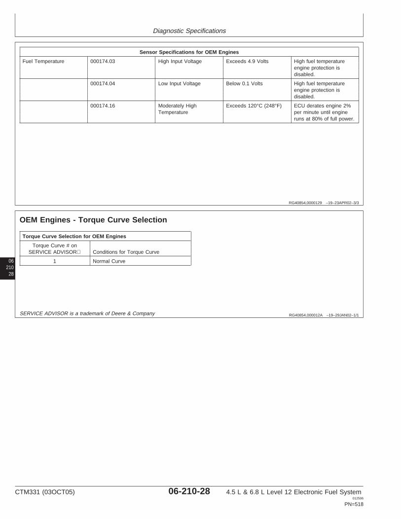
Diagnostic Specifications
RG40854,0000129 –19–23APR02–3/3
Sensor Specifications for OEM Engines
Fuel Temperature 000174.03 High Input Voltage Exceeds 4.9 Volts High fuel temperatureengine protection isdisabled.
000174.04 Low Input Voltage Below 0.1 Volts High fuel temperatureengine protection isdisabled.
000174.16 Moderately High Exceeds 120°C (248°F) ECU derates engine 2%Temperature per minute until engine
runs at 80% of full power.
06210
28
RG40854,000012A –19–29JAN02–1/1
OEM Engines - Torque Curve Selection
Torque Curve Selection for OEM Engines
Torque Curve # onSERVICE ADVISOR Conditions for Torque Curve
1 Normal Curve
SERVICE ADVISOR is a trademark of Deere & Company
CTM331 (03OCT05) 06-210-28 4.5 L & 6.8 L Level 12 Electronic Fuel System012506
PN=518
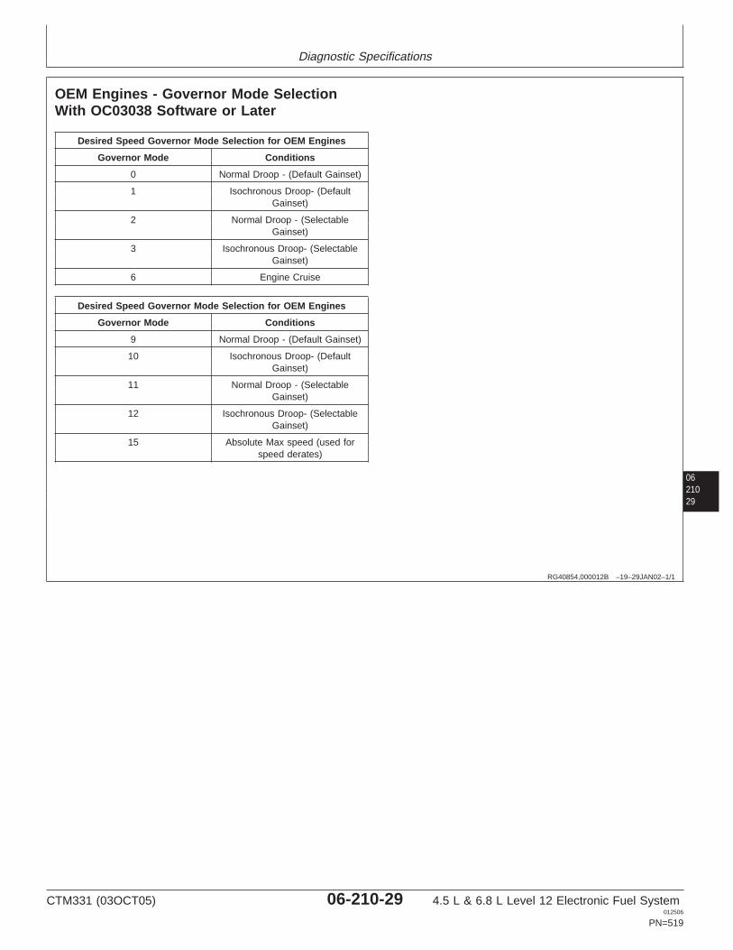
Diagnostic Specifications
0621029
RG40854,000012B –19–29JAN02–1/1
OEM Engines - Governor Mode SelectionWith OC03038 Software or Later
Desired Speed Governor Mode Selection for OEM Engines
Governor Mode Conditions
0 Normal Droop - (Default Gainset)
1 Isochronous Droop- (DefaultGainset)
2 Normal Droop - (SelectableGainset)
3 Isochronous Droop- (SelectableGainset)
6 Engine Cruise
Desired Speed Governor Mode Selection for OEM Engines
Governor Mode Conditions
9 Normal Droop - (Default Gainset)
10 Isochronous Droop- (DefaultGainset)
11 Normal Droop - (SelectableGainset)
12 Isochronous Droop- (SelectableGainset)
15 Absolute Max speed (used forspeed derates)
CTM331 (03OCT05) 06-210-29 4.5 L & 6.8 L Level 12 Electronic Fuel System012506
PN=519
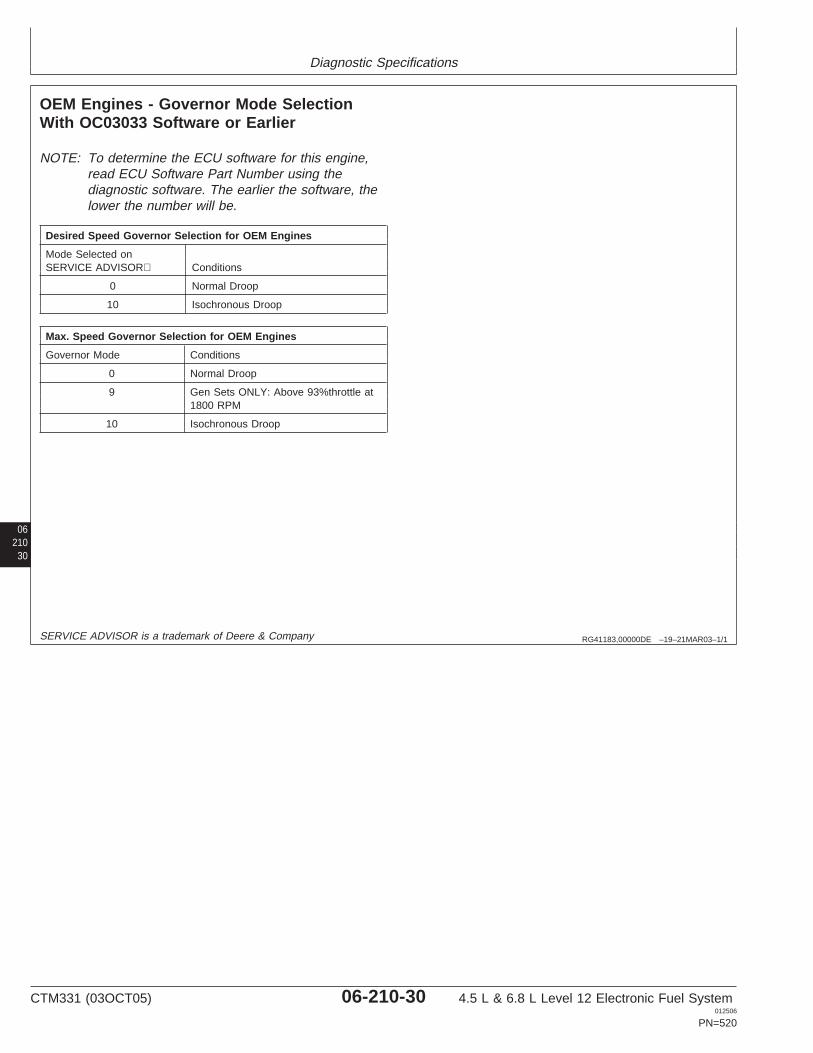
Diagnostic Specifications
06210
30
RG41183,00000DE –19–21MAR03–1/1
OEM Engines - Governor Mode SelectionWith OC03033 Software or Earlier
NOTE: To determine the ECU software for this engine,read ECU Software Part Number using thediagnostic software. The earlier the software, thelower the number will be.
Desired Speed Governor Selection for OEM Engines
Mode Selected onSERVICE ADVISOR Conditions
0 Normal Droop
10 Isochronous Droop
Max. Speed Governor Selection for OEM Engines
Governor Mode Conditions
0 Normal Droop
9 Gen Sets ONLY: Above 93%throttle at1800 RPM
10 Isochronous Droop
SERVICE ADVISOR is a trademark of Deere & Company
CTM331 (03OCT05) 06-210-30 4.5 L & 6.8 L Level 12 Electronic Fuel System012506
PN=520
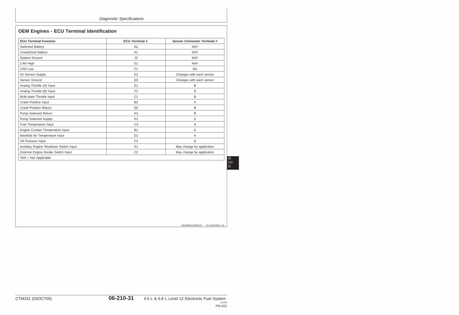
Diagnostic Specifications
0621031
RG40854,000012C –19–29JAN02–1/1
OEM Engines - ECU Terminal Identification
ECU Terminal Function ECU Terminal # Sensor Connector Terminal #
Switched Battery A2 N/Aa
Unswitched Battery K1 N/Aa
System Ground J2 N/Aa
CAN High G1 N/Aa
CAN Low F1 NA
5V Sensor Supply E2 Changes with each sensor
Sensor Ground D3 Changes with each sensor
Analog Throttle (A) Input E1 B
Analog Throttle (B) Input F2 B
Multi-state Throttle Input C1 B
Crank Position Input B2 A
Crank Position Return D2 B
Pump Solenoid Return A3 B
Pump Solenoid Supply K2 A
Fuel Temperature Input C3 A
Engine Coolant Temperature Input B1 A
Manifold Air Temperature Input D1 A
Oil Pressure Input F3 B
Auxiliary Engine Shutdown Switch Input A1 May change by application
External Engine Derate Switch Input C2 May change by applicationaN/A = Not Applicable
CTM331 (03OCT05) 06-210-31 4.5 L & 6.8 L Level 12 Electronic Fuel System012506
PN=521
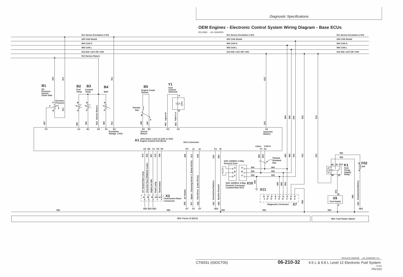
Diagnostic Specifications
RG41221,0000106 –19–31MAR03–1/1
OEM Engines - Electronic Control System Wiring Diagram - Base ECUs
SE3- Focus 12 (ECU)
B5
t
B3
914
461
448
447
Twisted ShieldedPair
X10
X11
SAE J1939/11 3-WayDeutsch Term
SAE J1939/11 3-Way
905
904
C
B
A
012 IGN +12V OR +24V
012
01
2
020
905
904
905 CAN L
904 CAN H
020 CAN Shield
012
01
2
020
D3B1 D2 B2
J2
A2
F1 G1
B
C
A
B
B
A
SE2
Instrument PanelConnector
Hig
h/Lo
w Id
leC1
947
IncreasePressure
B1
A
B
C
F3
020
020
905
905
904
904
Ove
rrid
e S
hut D
N/B
link
Cod
esB3
918
911 Sensor Excitation (+5V)
012 IGN +12V OR +24V
905 CAN L
904 CAN H
020 CAN Shield
911 Sensor Excitation (+5V)
012 IGN +12V OR +24V
905 CAN L
904 CAN H
020 CAN Shield
911 Sensor Excitation (+5V)
SE2
463
MAT
D1
A
B
B4
FGHJ
Diagnostic Connector X7 050
020
905
904
904
905
020
N R
A
BCD AE
Sen
sor
Ret
urn
914 Sensor Return
CAN L CAN HK1
050
022
SE2
Uns
witc
hed
Bat
tery
022
Sys
tem
Gro
und
050
TempCoolant
467
SensorEngine Crank
ReturnSensor
Engine Control Unit (ECU)John Deere Level 12 (12V or 24V)
BatterySwitched
Located Near ECUDeutsch Connector
ECU Connector
Inje
ct L
o 49
3
A3
491
K2
Inje
ct H
i
A
B
Y1
A1
SolenoidControlFuel
911
E2
911
Voltage (+5V)Excitation
428
t
TempFuel
A
B
B2
C3
Air
Hea
ted
Wai
t Lam
p
G2
474
SE2
A
050050 050 050
PairTwisted
911
911
Clean SideSensorPressureOil
914
85 87 87A
86 30
K1
050
062
050
RelaySupplyPumpFuel
F0210A
A
B
SE2
Uns
witc
hed
Bat
tery
002
X9Fuel Heater
A
050
B
072
SE4- Fuel Heater Option
012
01
2
Faul
t Lam
p
G3
473
H X3
Tach
omet
er
E3
439
K
K3
Air
Hea
ter
429
J1
Spa
re -
Sou
rcin
g D
river
2 (
Ear
ly E
CU
s)41
7
UT
417
UT
429
J1
Fan
Driv
er (
Late
r E
CU
s)41
8
UT
418
RG12882 –19–31MAR03
CTM331 (03OCT05) 06-210-32 4.5 L & 6.8 L Level 12 Electronic Fuel System012506
PN=522
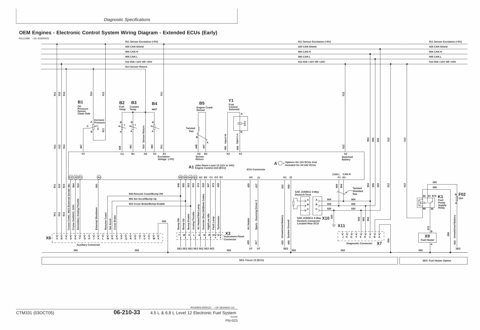
Diagnostic Specifications
RG40854,0000121 –19–28JAN02–1/1
OEM Engines - Electronic Control System Wiring Diagram - Extended ECUs (Early)
SE3- Focus 12 (ECU)
B5
t
B3
914
461
448
447
Twisted ShieldedPair
X10
X11
SAE J1939/11 3-WayDeutsch Term
SAE J1939/11 3-Way
905
904
C
B
A
012 IGN +12V OR +24V
012
01
2
020
905
904
905 CAN L
904 CAN H
020 CAN Shield
012
01
2
020
D3B1 D2 B2
J2
A2
F1 G1
B
C
A
B
B
A
SE2
Instrument PanelConnector
Hig
h/Lo
w Id
le
C1
947
IncreasePressure
B1
A
B
C
F3
020
020
905
905
904
904
Ove
rrid
e S
hut D
N/B
link
Cod
es
B3
918
911 Sensor Excitation (+5V)
012 IGN +12V OR +24V
905 CAN L
904 CAN H
020 CAN Shield
911 Sensor Excitation (+5V)
012 IGN +12V OR +24V
905 CAN L
904 CAN H
020 CAN Shield
911 Sensor Excitation (+5V)
SE2
463
MAT
D1
A
B
B4
FGHJ
Diagnostic Connector X7 050
020
905
904
904
905
020
N R
A
BCD AE
911
91
1 91
1
Sen
sor
Ret
urn
914 Sensor Return
CAN L CAN HK1
050
022
SE2
Uns
witc
hed
Bat
tery
022
Sys
tem
Gro
und
050
TempCoolant
467
SensorEngine Crank
ReturnSensor
Engine Control Unit (ECU)John Deere Level 12 (12V or 24V)
Options On 12V ECUs AndIncluded On All 24V ECUs
BatterySwitched
Located Near ECUDeutsch Connector
ECU Connector
Inje
ct L
o 49
3
A3
491
K2
Inje
ct H
i
A
B
Y1
A1A
SolenoidControlFuel
911
E2
911
Voltage (+5V)Excitation
428
t
TempFuel
A
B
B2
C3
A B C D E F G H J K L M N O
911
012
01
2 01
2 01
2
914
91
4 91
4 91
4
Res
ume
Coa
st
F2
Sec
onda
ry A
nalo
g T
hrot
tle91
3
J3
Cru
ise
On/
ISO
C. G
OV.
954
C2
Cru
ise
CA
NC
. RE
S./E
xter
nal D
erat
e98
1
Set
Acc
el
Cru
se B
rake
Air
Hea
ted
Wai
t Lam
p
G2
474
SE2
A
Ana
log
Thr
ottle
E1
915
SE2
L
SE2 SE2 SE2
Bum
p E
nabl
e
H1H3 H2
955
936
B
ump
DN
Bum
p U
p
923
T W X
936 Resume Coast/Bump DN
955 Set Accel/Bump Up
923 Cruse Brake/Bump Enable
050050050 050 050
050
PairTwisted
911
911
Clean SideSensorPressureOil
914
85 87 87A
86 30
K1
050
062
050
RelaySupplyPumpFuel
F0210A
A
B
SE2
Uns
witc
hed
Bat
tery
002
X9Fuel Heater
A
050
B
072
SE4- Fuel Heater Option
X6
Auxillary Connector
012
01
2
Faul
t Lam
p
G3
473
H X3P Q R S T U V W X
A1
Ext
erna
l Shu
tdow
n94
1
Tach
omet
er
E3
439
K
K3
Air
Hea
ter
429
J1
Spa
re -
Sou
rcin
g D
river
241
7
UT
417
UT42
9
=
RG11986 –19–31MAR03
CTM331 (03OCT05) 06-210-33 4.5 L & 6.8 L Level 12 Electronic Fuel System012506
PN=523
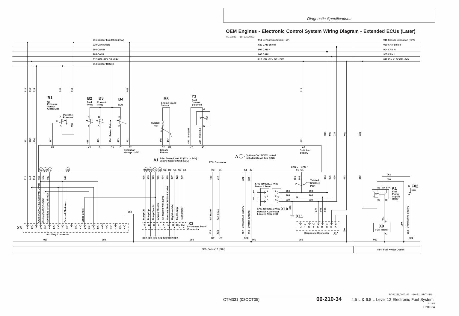
Diagnostic Specifications
RG41221,0000105 –19–31MAR03–1/1
OEM Engines - Electronic Control System Wiring Diagram - Extended ECUs (Later)
SE3- Focus 12 (ECU)
B5
t
B3
914
461
448
447
Twisted ShieldedPair
X10
X11
SAE J1939/11 3-WayDeutsch Term
SAE J1939/11 3-Way
905
904
C
B
A
012 IGN +12V OR +24V
012
01
2
020
905
904
905 CAN L
904 CAN H
020 CAN Shield
012
01
2
020
D3B1 D2 B2
J2
A2
F1 G1
B
C
A
B
B
A
SE2
Instrument PanelConnector
Hig
h/Lo
w Id
leC1
947
IncreasePressure
B1
A
B
C
F3
020
020
905
905
904
904
Ove
rrid
e S
hut D
N/B
link
Cod
esB3
918
911 Sensor Excitation (+5V)
012 IGN +12V OR +24V
905 CAN L
904 CAN H
020 CAN Shield
911 Sensor Excitation (+5V)
012 IGN +12V OR +24V
905 CAN L
904 CAN H
020 CAN Shield
911 Sensor Excitation (+5V)
SE2
463
MAT
D1
A
B
B4
FGHJ
Diagnostic Connector X7 050
020
905
904
904
905
020
N R
A
BCD AE
911
91
1 91
1
Sen
sor
Ret
urn
914 Sensor Return
CAN L CAN HK1
050
022
SE2
Uns
witc
hed
Bat
tery
022
Sys
tem
Gro
und
050
TempCoolant
467
SensorEngine Crank
ReturnSensor
Engine Control Unit (ECU)John Deere Level 12 (12V or 24V)
Options On 12V ECUs AndIncluded On All 24V ECUs
BatterySwitched
Located Near ECUDeutsch Connector
ECU Connector
Inje
ct L
o 49
3
A3
491
K2
Inje
ct H
i
A
B
Y1
A1A
SolenoidControlFuel
911
E2
911
Voltage (+5V)Excitation
428
t
TempFuel
A
B
B2
C3
A B C D E F G H J K L M N O
012
01
2 01
2
914
91
4 91
4
F2
Sec
onda
ry A
nalo
g T
hrot
tle91
3
J3
Cru
ise
On/
ISO
C. G
OV.
954
C2
Cru
ise
CA
NC
. RE
S./E
xter
nal D
erat
e98
1
Cru
se B
rake
Air
Hea
ted
Wai
t Lam
p
G2
474
SE2
A
Ana
log
Thr
ottle
E1
915
SE2
L
SE2 SE2 SE2
Bum
p E
nabl
e
H1H3 H2
955
936
B
ump
DN
Bum
p U
p
923
T W X
050050050 050 050
050
PairTwisted
911
911
Clean SideSensorPressureOil
914
85 87 87A
86 30
K1
050
062
050
RelaySupplyPumpFuel
F0210A
A
B
SE2
Uns
witc
hed
Bat
tery
002
X9Fuel Heater
A
050
B
072
SE4- Fuel Heater Option
X6
Auxillary Connector
012
01
2
Faul
t Lam
p
G3
473
H X3P Q R S T U V W X
A1
Ext
erna
l Shu
tdow
n94
1
Tach
omet
er
E3
439
K
K3
Air
Hea
ter
429
J1
Fan
Driv
e41
8
UT
418
UT
429
=
RG12883 –19–31MAR03
CTM331 (03OCT05) 06-210-34 4.5 L & 6.8 L Level 12 Electronic Fuel System012506
PN=524
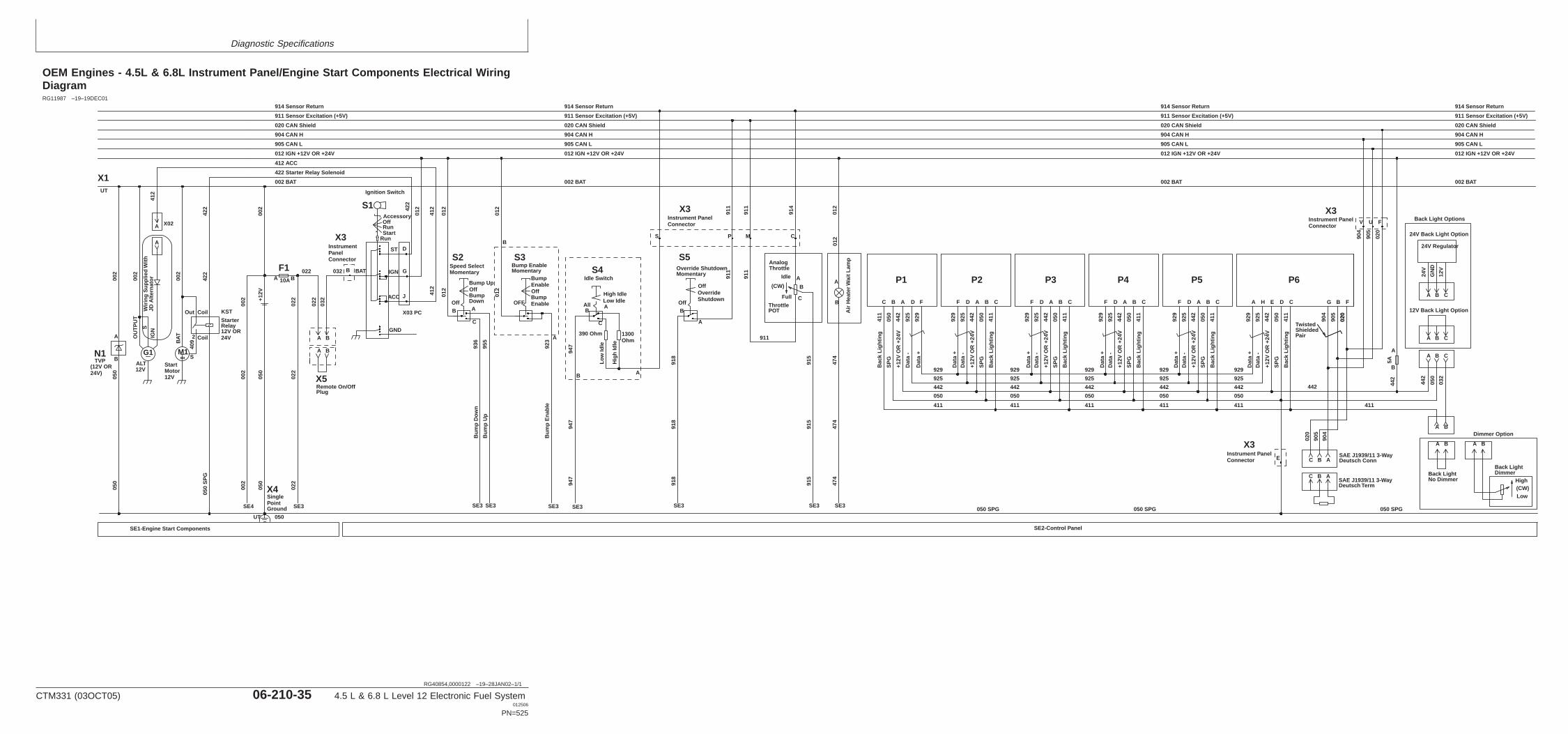
Diagnostic Specifications
RG40854,0000122 –19–28JAN02–1/1
OEM Engines - 4.5L & 6.8L Instrument Panel/Engine Start Components Electrical WiringDiagram
B
A
Air
Hea
ter W
ait L
amp
012
B
F110A
SinglePointGround
+12V
050
050
050
002 BAT
422 Starter Relay Solenoid
412 ACC
012 IGN +12V OR +24V
002
905 CAN L
904 CAN H
020 CAN Shield
022
022
A
X4
BA
C B A
TwistedShielded Pair
050 SPG
ABC
SAE J1939/11 3-WayDeutsch Term
SAE J1939/11 3-WayDeutsch Conn
050 SPG
24V Regulator
A B C
A B C
12V Back Light Option
High
Low(CW)
A B
Back LightDimmer
FBG
020
904
C
Bac
k Li
ghtin
g
41
1
411
SP
G
050
DA B C
24V
GN
D
12V
24V Back Light Option
032
050
442
904
905
020
442
442
442
+12V
OR
+24
V
E
925
D
ata
-
H
929
D
ata
+
AC
Bac
k Li
ghtin
g
41
1
SP
G
050
B
442
+12V
OR
+24
V
A
925
D
ata
-
D
929
D
ata
+
FC
Bac
k Li
ghtin
g
41
1
SP
G
050
B
442
+12V
OR
+24
V
A
925
D
ata
-
D
929
D
ata
+
FC
Bac
k Li
ghtin
g
41
1
SP
G
050
B
442
+1
2V O
R +
24V
A
925
D
ata
-
D
929
D
ata
+
FC
Bac
k Li
ghtin
g
41
1
SP
G
050
B
442
+12V
OR
+24
V
A
925
D
ata
-
D
929
D
ata
+
FC B A D F
929
D
ata
+
925
D
ata
-
442
+12V
OR
+24
V
SP
G
050
Bac
k Li
ghtin
g
41
1
SE2-Control Panel
411
050
442
925
929
411
050
442
925
929
411
050
442
925
929
411
050
442
925
929
411
050
442
925
929
Back Light No Dimmer
Back Light Options
BA
Dimmer Option
020
905
020
905
904
A
B
5A
Ignition Switch
AccessoryOffRunStart
Run
BAT
ST
IGN
GND
422
S2Speed SelectMomentary
Bump UpOffBump DownOffAB
C
SE3
Bum
p D
own
SE3
Bum
p U
p
S3Bump EnableMomentary
Bump EnableOffBump EnableOFF
A
B
SE3
S4Idle Switch
All A
C
Hig
h Id
le
Low IdleHigh Idle
Low
Idle
390 Ohm
SE3
947
012
012
012
012
012
936
955
1300 Ohm
947
947
Bum
p E
nabl
e92
3
B
B A
S5Override Shutdown Momentary
Off
A
B
Override Shutdown
Off
SE3
918
918
918
911 Sensor Excitation (+5V)
911
911
B
E
V U F
ACC
SE3
UT
X3
X03 PC
D
G
J
412
412
S1
X3
X3
P
X3
P1 P2 P3 P4 P5 P6
BA
BA
X5Remote On/OffPlug
N1(12V OR 24V)
G1 M1
KST
ALT12V
StartMotor12V
StarterRelay12V OR 24V
002
SIG
N
050
SP
G
SE1-Engine Start Components
TVP
002
002
050
050
412
409
A
Wiri
ng S
uppl
ied
With
JD A
ltern
ator
X1
Out Coil
2 Coil
S
OU
TP
UT
BATA
B
A X02
422
42
2
UT
022
022
032
032022
002
002
SE4
002
Idle
Full
(CW)
AnalogThrottle
ThrottlePOT
B
C
A
914 Sensor Return
002 BAT
012 IGN +12V OR +24V
905 CAN L
904 CAN H
020 CAN Shield
911 Sensor Excitation (+5V)
914 Sensor Return
002 BAT
012 IGN +12V OR +24V
905 CAN L
904 CAN H
020 CAN Shield
911 Sensor Excitation (+5V)
914 Sensor Return
002 BAT
012 IGN +12V OR +24V
905 CAN L
904 CAN H
020 CAN Shield
911 Sensor Excitation (+5V)
914 Sensor Return
SE3
911
911
911
915
915
915
914
M C
SE3
474
474
474
012
050 SPG
S
Instrument PanelConnector
Instrument PanelConnector
Instrument PanelConnector
Instrument PanelConnector
RG11987 –19–19DEC01
CTM331 (03OCT05) 06-210-35 4.5 L & 6.8 L Level 12 Electronic Fuel System012506
PN=525

Diagnostic Specifications
RG40854,000016C –19–23APR02–1/2
Skidders - Sensor Specifications
The specifications shown below are voltage, pressure,and temperature parameters that the Engine Control Unit(ECU) uses to determine whether a Diagnostic TroubleCode (DTC) is set for a given sensor.
Continued on next page
06210
36
CTM331 (03OCT05) 06-210-36 4.5 L & 6.8 L Level 12 Electronic Fuel System012506
PN=526
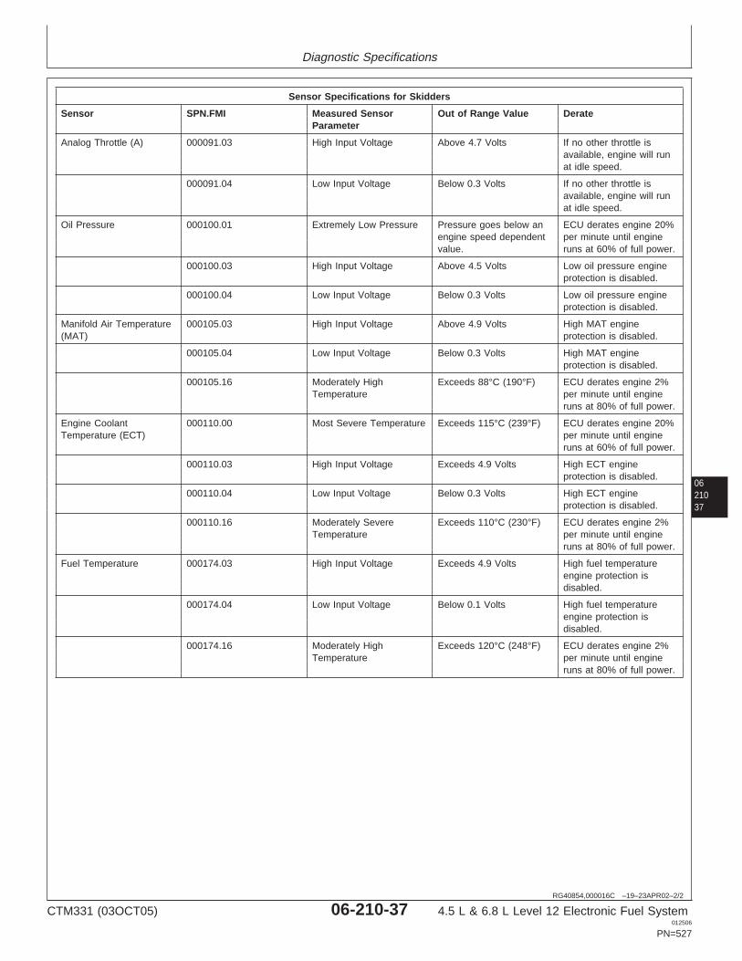
Diagnostic Specifications
0621037
RG40854,000016C –19–23APR02–2/2
Sensor Specifications for Skidders
Sensor SPN.FMI Measured Sensor Out of Range Value DerateParameter
Analog Throttle (A) 000091.03 High Input Voltage Above 4.7 Volts If no other throttle isavailable, engine will runat idle speed.
000091.04 Low Input Voltage Below 0.3 Volts If no other throttle isavailable, engine will runat idle speed.
Oil Pressure 000100.01 Extremely Low Pressure Pressure goes below an ECU derates engine 20%engine speed dependent per minute until enginevalue. runs at 60% of full power.
000100.03 High Input Voltage Above 4.5 Volts Low oil pressure engineprotection is disabled.
000100.04 Low Input Voltage Below 0.3 Volts Low oil pressure engineprotection is disabled.
Manifold Air Temperature 000105.03 High Input Voltage Above 4.9 Volts High MAT engine(MAT) protection is disabled.
000105.04 Low Input Voltage Below 0.3 Volts High MAT engineprotection is disabled.
000105.16 Moderately High Exceeds 88°C (190°F) ECU derates engine 2%Temperature per minute until engine
runs at 80% of full power.
Engine Coolant 000110.00 Most Severe Temperature Exceeds 115°C (239°F) ECU derates engine 20%Temperature (ECT) per minute until engine
runs at 60% of full power.
000110.03 High Input Voltage Exceeds 4.9 Volts High ECT engineprotection is disabled.
000110.04 Low Input Voltage Below 0.3 Volts High ECT engineprotection is disabled.
000110.16 Moderately Severe Exceeds 110°C (230°F) ECU derates engine 2%Temperature per minute until engine
runs at 80% of full power.
Fuel Temperature 000174.03 High Input Voltage Exceeds 4.9 Volts High fuel temperatureengine protection isdisabled.
000174.04 Low Input Voltage Below 0.1 Volts High fuel temperatureengine protection isdisabled.
000174.16 Moderately High Exceeds 120°C (248°F) ECU derates engine 2%Temperature per minute until engine
runs at 80% of full power.
CTM331 (03OCT05) 06-210-37 4.5 L & 6.8 L Level 12 Electronic Fuel System012506
PN=527
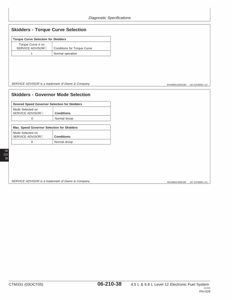
Diagnostic Specifications
RG40854,000016D –19–21FEB02–1/1
Skidders - Torque Curve Selection
Torque Curve Selection for Skidders
Torque Curve # onSERVICE ADVISOR Conditions for Torque Curve
1 Normal operation
SERVICE ADVISOR is a trademark of Deere & Company
06210
38
RG40854,000016F –19–21FEB02–1/1
Skidders - Governor Mode Selection
Desired Speed Governor Selection for Skidders
Mode Selected onSERVICE ADVISOR Conditions
0 Normal droop
Max. Speed Governor Selection for Skidders
Mode Selected onSERVICE ADVISOR Conditions:
9 Normal droop
SERVICE ADVISOR is a trademark of Deere & Company
CTM331 (03OCT05) 06-210-38 4.5 L & 6.8 L Level 12 Electronic Fuel System012506
PN=528

Diagnostic Specifications
0621039
RG40854,0000170 –19–21FEB02–1/1
Skidders - ECU Terminal Identification
ECU Terminal Function ECU Terminal # Sensor Connector Terminal #
Switched Battery A2 N/Aa
Unswitched Battery K1 N/Aa
System Ground J2 N/Aa
CAN High G1 N/Aa
CAN Low F1 NA
5V Sensor Supply E2 Changes with each sensor
Sensor Ground D3 Changes with each sensor
Analog Throttle (A) Input E1 B
Multi-state Throttle Input C1 B
Crank Position Input B2 A
Crank Position Return D2 B
Pump Solenoid Return A3 B
Pump Solenoid Supply K2 A
Fuel Temperature Input C3 A
Engine Coolant Temperature Input B1 A
Manifold Air Temperature Input D1 A
Oil Pressure Input F3 BaN/A = Not Applicable
CTM331 (03OCT05) 06-210-39 4.5 L & 6.8 L Level 12 Electronic Fuel System012506
PN=529
Diagnostic Specifications
RG40854,0000140 –19–23APR02–1/2
Telehandlers - Sensor Specifications
The specifications shown below are voltage, pressure,and temperature parameters that the Engine Control Unit(ECU) uses to determine whether a Diagnostic TroubleCode (DTC) is set for a given sensor.
Continued on next page
06210
40
CTM331 (03OCT05) 06-210-40 4.5 L & 6.8 L Level 12 Electronic Fuel System012506
PN=530
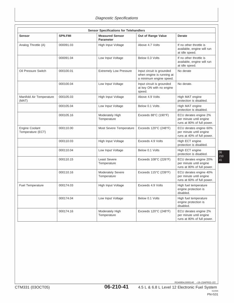
Diagnostic Specifications
0621041
RG40854,0000140 –19–23APR02–2/2
Sensor Specifications for Telehandlers
Sensor SPN.FMI Measured Sensor Out of Range Value DerateParameter
Analog Throttle (A) 000091.03 High Input Voltage Above 4.7 Volts If no other throttle isavailable, engine will runat idle speed.
000091.04 Low Input Voltage Below 0.3 Volts If no other throttle isavailable, engine will runat idle speed.
Oil Pressure Switch 000100.01 Extremely Low Pressure Input circuit is grounded No deratewhen engine is running ata minimum engine speed.
000100.04 Low Input Voltage Input circuit is grounded No derate.at key ON with no enginespeed.
Manifold Air Temperature 000105.03 High Input Voltage Above 4.9 Volts High MAT engine(MAT) protection is disabled.
000105.04 Low Input Voltage Below 0.1 Volts High MAT engineprotection is disabled.
000105.16 Moderately High Exceeds 88°C (190°F) ECU derates engine 2%Temperature per minute until engine
runs at 80% of full power.
Engine Coolant 000110.00 Most Severe Temperature Exceeds 120°C (248°F) ECU derates engine 60%Temperature (ECT) per minute until engine
runs at 40% of full power.
000110.03 High Input Voltage Exceeds 4.9 Volts High ECT engineprotection is disabled.
000110.04 Low Input Voltage Below 0.1 Volts High ECT engineprotection is disabled.
000110.15 Least Severe Exceeds 108°C (226°F) ECU derates engine 20%Temperature per minute until engine
runs at 80% of full power.
000110.16 Moderately Severe Exceeds 115°C (239°F) ECU derates engine 40%Temperature per minute until engine
runs at 60% of full power.
Fuel Temperature 000174.03 High Input Voltage Exceeds 4.9 Volts High fuel temperatureengine protection isdisabled.
000174.04 Low Input Voltage Below 0.1 Volts High fuel temperatureengine protection isdisabled.
000174.16 Moderately High Exceeds 120°C (248°F) ECU derates engine 2%Temperature per minute until engine
runs at 80% of full power.
CTM331 (03OCT05) 06-210-41 4.5 L & 6.8 L Level 12 Electronic Fuel System012506
PN=531
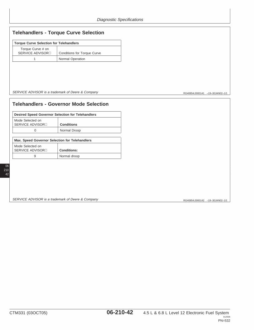
Diagnostic Specifications
RG40854,0000141 –19–30JAN02–1/1
Telehandlers - Torque Curve Selection
Torque Curve Selection for Telehandlers
Torque Curve # onSERVICE ADVISOR Conditions for Torque Curve
1 Normal Operation
SERVICE ADVISOR is a trademark of Deere & Company
06210
42
RG40854,0000142 –19–30JAN02–1/1
Telehandlers - Governor Mode Selection
Desired Speed Governor Selection for Telehandlers
Mode Selected onSERVICE ADVISOR Conditions
0 Normal Droop
Max. Speed Governor Selection for Telehandlers
Mode Selected onSERVICE ADVISOR Conditions:
9 Normal droop
SERVICE ADVISOR is a trademark of Deere & Company
CTM331 (03OCT05) 06-210-42 4.5 L & 6.8 L Level 12 Electronic Fuel System012506
PN=532
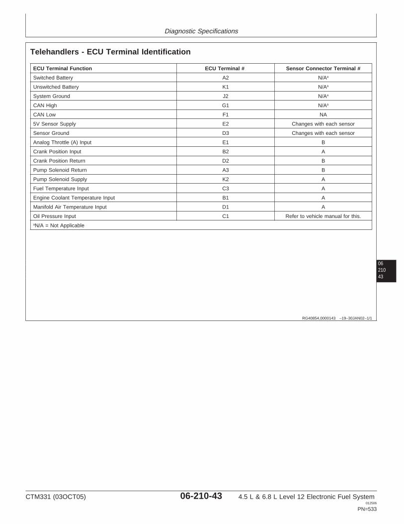
Diagnostic Specifications
0621043
RG40854,0000143 –19–30JAN02–1/1
Telehandlers - ECU Terminal Identification
ECU Terminal Function ECU Terminal # Sensor Connector Terminal #
Switched Battery A2 N/Aa
Unswitched Battery K1 N/Aa
System Ground J2 N/Aa
CAN High G1 N/Aa
CAN Low F1 NA
5V Sensor Supply E2 Changes with each sensor
Sensor Ground D3 Changes with each sensor
Analog Throttle (A) Input E1 B
Crank Position Input B2 A
Crank Position Return D2 B
Pump Solenoid Return A3 B
Pump Solenoid Supply K2 A
Fuel Temperature Input C3 A
Engine Coolant Temperature Input B1 A
Manifold Air Temperature Input D1 A
Oil Pressure Input C1 Refer to vehicle manual for this.aN/A = Not Applicable
CTM331 (03OCT05) 06-210-43 4.5 L & 6.8 L Level 12 Electronic Fuel System012506
PN=533

Diagnostic Specifications
RG40854,0000014 –19–20AUG02–1/3
Tractors - Sensor Specifications
The specifications shown below are voltage, pressure,and temperature parameters that the Engine Control Unit(ECU) uses to determine whether a Diagnostic TroubleCode (DTC) is set for a given sensor.
Continued on next page
06210
44
CTM331 (03OCT05) 06-210-44 4.5 L & 6.8 L Level 12 Electronic Fuel System012506
PN=534
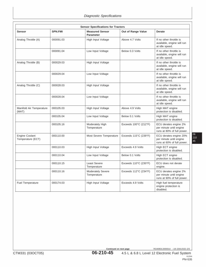
Diagnostic Specifications
0621045
RG40854,0000014 –19–20AUG02–2/3
Sensor Specifications for Tractors
Sensor SPN.FMI Measured Sensor Out of Range Value DerateParameter
Analog Throttle (A) 000091.03 High Input Voltage Above 4.7 Volts If no other throttle isavailable, engine will runat idle speed.
000091.04 Low Input Voltage Below 0.3 Volts If no other throttle isavailable, engine will runat idle speed.
Analog Throttle (B) 000029.03 High Input Voltage If no other throttle isavailable, engine will runat idle speed.
000029.04 Low Input Voltage If no other throttle isavailable, engine will runat idle speed.
Analog Throttle (C) 000028.03 High Input Voltage If no other throttle isavailable, engine will runat idle speed.
000028.04 Low Input Voltage If no other throttle isavailable, engine will runat idle speed.
Manifold Air Temperature 000105.03 High Input Voltage Above 4.9 Volts High MAT engine(MAT) protection is disabled.
000105.04 Low Input Voltage Below 0.1 Volts High MAT engineprotection is disabled.
000105.16 Moderately High Exceeds 100°C (212°F) ECU derates engine 2%Temperature per minute until engine
runs at 80% of full power.
Engine Coolant 000110.00 Most Severe Temperature Exceeds 115°C (239°F) ECU derates engine 20%Temperature (ECT) per minute until engine
runs at 60% of full power.
000110.03 High Input Voltage Exceeds 4.9 Volts High ECT engineprotection is disabled.
000110.04 Low Input Voltage Below 0.1 Volts High ECT engineprotection is disabled.
000110.15 Least Severe Exceeds 110°C (230°F) ECU does not derateTemperature engine.
000110.16 Moderately Severe Exceeds 112°C (234°F) ECU derates engine 2%Temperature per minute until engine
runs at 90% of full power.
Fuel Temperature 000174.03 High Input Voltage Exceeds 4.9 Volts High fuel temperatureengine protection isdisabled.
CTM331 (03OCT05) 06-210-45 4.5 L & 6.8 L Level 12 Electronic Fuel System012506
PN=535
Continued on next page
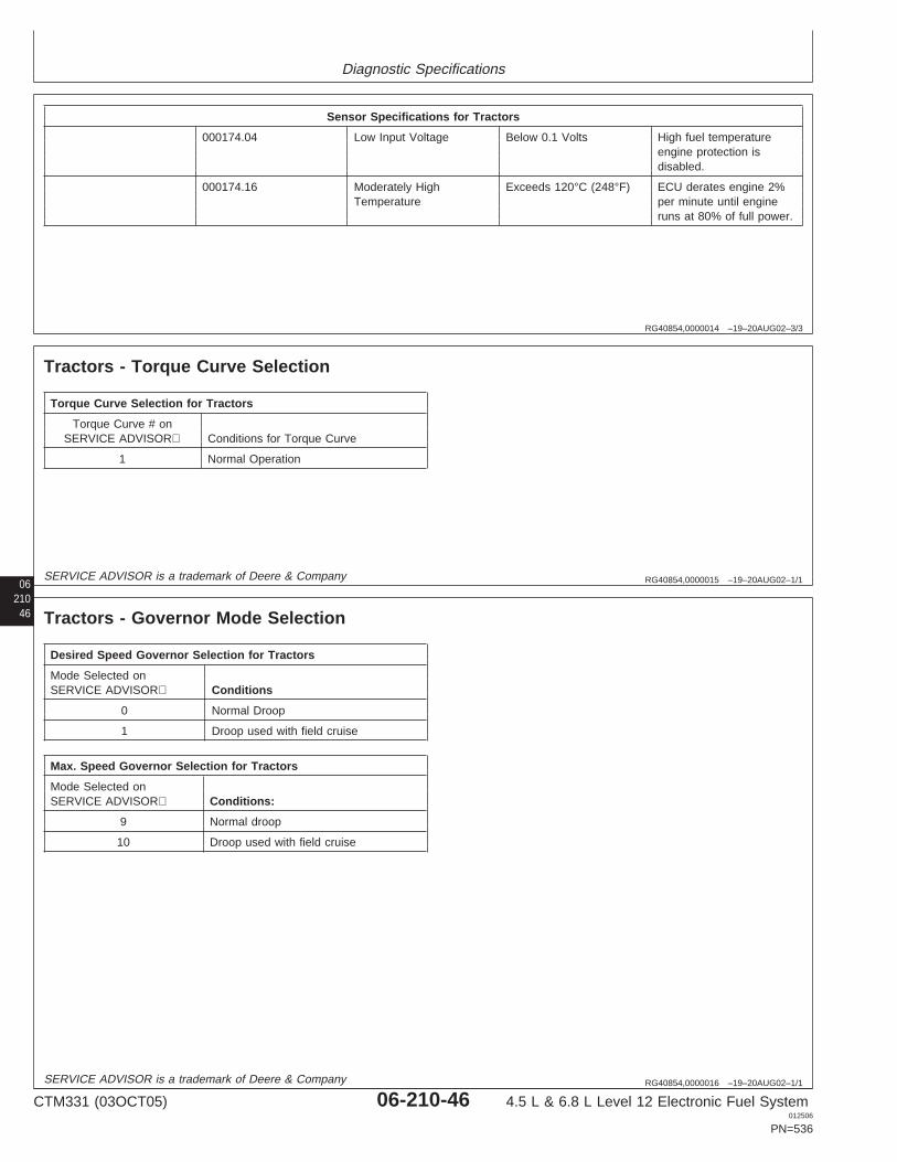
Diagnostic Specifications
RG40854,0000014 –19–20AUG02–3/3
Sensor Specifications for Tractors
000174.04 Low Input Voltage Below 0.1 Volts High fuel temperatureengine protection isdisabled.
000174.16 Moderately High Exceeds 120°C (248°F) ECU derates engine 2%Temperature per minute until engine
runs at 80% of full power.
06 RG40854,0000015 –19–20AUG02–1/1
Tractors - Torque Curve Selection
Torque Curve Selection for Tractors
Torque Curve # onSERVICE ADVISOR Conditions for Torque Curve
1 Normal Operation
21046
SERVICE ADVISOR is a trademark of Deere & Company
RG40854,0000016 –19–20AUG02–1/1
Tractors - Governor Mode Selection
Desired Speed Governor Selection for Tractors
Mode Selected onSERVICE ADVISOR Conditions
0 Normal Droop
1 Droop used with field cruise
Max. Speed Governor Selection for Tractors
Mode Selected onSERVICE ADVISOR Conditions:
9 Normal droop
10 Droop used with field cruise
SERVICE ADVISOR is a trademark of Deere & Company
CTM331 (03OCT05) 06-210-46 4.5 L & 6.8 L Level 12 Electronic Fuel System012506
PN=536
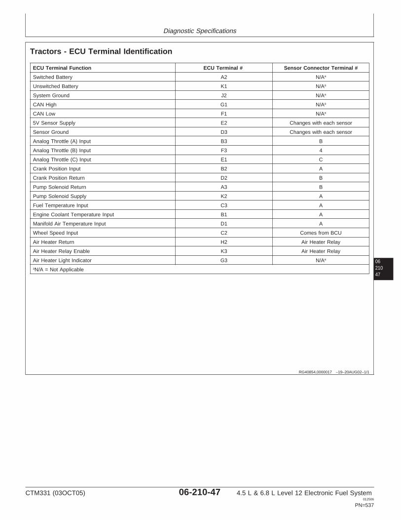
Diagnostic Specifications
0621047
RG40854,0000017 –19–20AUG02–1/1
Tractors - ECU Terminal Identification
ECU Terminal Function ECU Terminal # Sensor Connector Terminal #
Switched Battery A2 N/Aa
Unswitched Battery K1 N/Aa
System Ground J2 N/Aa
CAN High G1 N/Aa
CAN Low F1 N/Aa
5V Sensor Supply E2 Changes with each sensor
Sensor Ground D3 Changes with each sensor
Analog Throttle (A) Input B3 B
Analog Throttle (B) Input F3 4
Analog Throttle (C) Input E1 C
Crank Position Input B2 A
Crank Position Return D2 B
Pump Solenoid Return A3 B
Pump Solenoid Supply K2 A
Fuel Temperature Input C3 A
Engine Coolant Temperature Input B1 A
Manifold Air Temperature Input D1 A
Wheel Speed Input C2 Comes from BCU
Air Heater Return H2 Air Heater Relay
Air Heater Relay Enable K3 Air Heater Relay
Air Heater Light Indicator G3 N/Aa
aN/A = Not Applicable
CTM331 (03OCT05) 06-210-47 4.5 L & 6.8 L Level 12 Electronic Fuel System012506
PN=537

Diagnostic Specifications
06210
48
CTM331 (03OCT05) 06-210-48 4.5 L & 6.8 L Level 12 Electronic Fuel System012506
PN=538
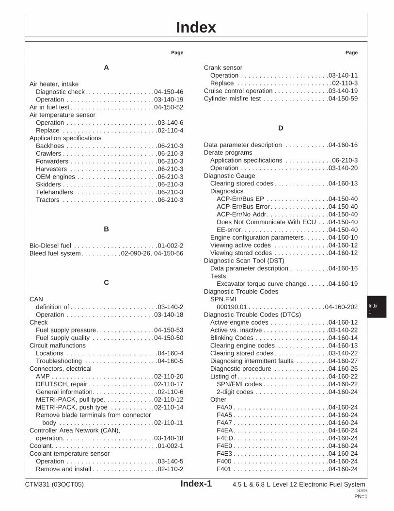
IndexPage Page
A Crank sensorOperation . . . . . . . . . . . . . . . . . . . . . . . .03-140-11Replace . . . . . . . . . . . . . . . . . . . . . . . . . .02-110-3Air heater, intake
Cruise control operation . . . . . . . . . . . . . . .03-140-19Diagnostic check. . . . . . . . . . . . . . . . . . .04-150-46Cylinder misfire test . . . . . . . . . . . . . . . . . .04-150-59Operation . . . . . . . . . . . . . . . . . . . . . . . .03-140-19
Air in fuel test . . . . . . . . . . . . . . . . . . . . . . .04-150-52Air temperature sensor
Operation . . . . . . . . . . . . . . . . . . . . . . . . .03-140-6DReplace . . . . . . . . . . . . . . . . . . . . . . . . . .02-110-4
Application specificationsData parameter description . . . . . . . . . . . .04-160-16Backhoes . . . . . . . . . . . . . . . . . . . . . . . . .06-210-3Derate programsCrawlers . . . . . . . . . . . . . . . . . . . . . . . . . .06-210-3
Application specifications . . . . . . . . . . . . .06-210-3Forwarders . . . . . . . . . . . . . . . . . . . . . . . .06-210-3Operation . . . . . . . . . . . . . . . . . . . . . . . .03-140-20Harvesters . . . . . . . . . . . . . . . . . . . . . . . .06-210-3
Diagnostic GaugeOEM engines . . . . . . . . . . . . . . . . . . . . . .06-210-3Clearing stored codes . . . . . . . . . . . . . . .04-160-13Skidders . . . . . . . . . . . . . . . . . . . . . . . . . .06-210-3DiagnosticsTelehandlers . . . . . . . . . . . . . . . . . . . . . . .06-210-3
ACP-Err/Bus EP . . . . . . . . . . . . . . . . .04-150-40Tractors . . . . . . . . . . . . . . . . . . . . . . . . . .06-210-3ACP-Err/Bus Error . . . . . . . . . . . . . . . .04-150-40ACP-Err/No Addr . . . . . . . . . . . . . . . . .04-150-40Does Not Communicate With ECU . . .04-150-40
B EE-error. . . . . . . . . . . . . . . . . . . . . . . .04-150-40Engine configuration parameters. . . . . . .04-160-10Viewing active codes . . . . . . . . . . . . . . .04-160-12Bio-Diesel fuel . . . . . . . . . . . . . . . . . . . . . . .01-002-2Viewing stored codes . . . . . . . . . . . . . . .04-160-12Bleed fuel system. . . . . . . . . . .02-090-26, 04-150-56
Diagnostic Scan Tool (DST)Data parameter description . . . . . . . . . . .04-160-16Tests
C Excavator torque curve change . . . . . .04-160-19Diagnostic Trouble Codes
CAN SPN.FMIIndxdefinition of . . . . . . . . . . . . . . . . . . . . . . . .03-140-2 000190.01 . . . . . . . . . . . . . . . . . . . . .04-160-2021Operation . . . . . . . . . . . . . . . . . . . . . . . .03-140-18 Diagnostic Trouble Codes (DTCs)
Check Active engine codes . . . . . . . . . . . . . . . .04-160-12Active vs. inactive . . . . . . . . . . . . . . . . . .03-140-22Fuel supply pressure. . . . . . . . . . . . . . . .04-150-53
Fuel supply quality . . . . . . . . . . . . . . . . .04-150-50 Blinking Codes . . . . . . . . . . . . . . . . . . . .04-160-14Clearing engine codes . . . . . . . . . . . . . .04-160-13Circuit malfunctions
Locations . . . . . . . . . . . . . . . . . . . . . . . . .04-160-4 Clearing stored codes . . . . . . . . . . . . . . .03-140-22Diagnosing intermittent faults . . . . . . . . .04-160-27Troubleshooting . . . . . . . . . . . . . . . . . . . .04-160-5
Connectors, electrical Diagnostic procedure . . . . . . . . . . . . . . .04-160-26Listing of . . . . . . . . . . . . . . . . . . . . . . . . .04-160-22AMP . . . . . . . . . . . . . . . . . . . . . . . . . . . .02-110-20
DEUTSCH, repair . . . . . . . . . . . . . . . . . .02-110-17 SPN/FMI codes . . . . . . . . . . . . . . . . . .04-160-222-digit codes . . . . . . . . . . . . . . . . . . . .04-160-24General information. . . . . . . . . . . . . . . . . .02-110-6
METRI-PACK, pull type. . . . . . . . . . . . . .02-110-12 OtherF4A0 . . . . . . . . . . . . . . . . . . . . . . . . . .04-160-24METRI-PACK, push type . . . . . . . . . . . .02-110-14
Remove blade terminals from connector F4A5 . . . . . . . . . . . . . . . . . . . . . . . . . .04-160-24F4A7 . . . . . . . . . . . . . . . . . . . . . . . . . .04-160-24body . . . . . . . . . . . . . . . . . . . . . . . . . .02-110-11
Controller Area Network (CAN), F4EA . . . . . . . . . . . . . . . . . . . . . . . . . .04-160-24F4ED. . . . . . . . . . . . . . . . . . . . . . . . . .04-160-24operation. . . . . . . . . . . . . . . . . . . . . . . . .03-140-18
Coolant. . . . . . . . . . . . . . . . . . . . . . . . . . . . .01-002-1 F4E0 . . . . . . . . . . . . . . . . . . . . . . . . . .04-160-24F4E3 . . . . . . . . . . . . . . . . . . . . . . . . . .04-160-24Coolant temperature sensor
Operation . . . . . . . . . . . . . . . . . . . . . . . . .03-140-5 F400 . . . . . . . . . . . . . . . . . . . . . . . . . .04-160-24F401 . . . . . . . . . . . . . . . . . . . . . . . . . .04-160-24Remove and install . . . . . . . . . . . . . . . . . .02-110-2
CTM331 (03OCT05) Index-1 4.5 L & 6.8 L Level 12 Electronic Fuel System012506
PN=1
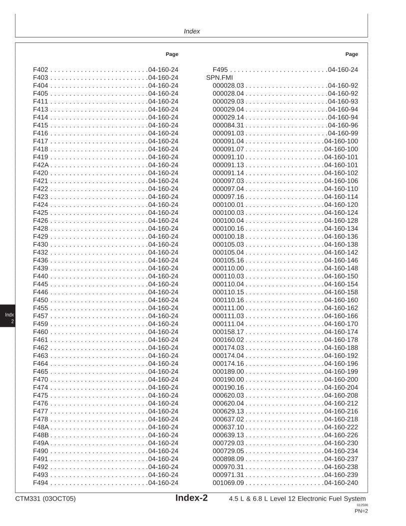
Index
Page Page
F402 . . . . . . . . . . . . . . . . . . . . . . . . . .04-160-24 F495 . . . . . . . . . . . . . . . . . . . . . . . . . .04-160-24SPN.FMIF403 . . . . . . . . . . . . . . . . . . . . . . . . . .04-160-24
F404 . . . . . . . . . . . . . . . . . . . . . . . . . .04-160-24 000028.03 . . . . . . . . . . . . . . . . . . . . . .04-160-92000028.04 . . . . . . . . . . . . . . . . . . . . . .04-160-92F405 . . . . . . . . . . . . . . . . . . . . . . . . . .04-160-24
F411 . . . . . . . . . . . . . . . . . . . . . . . . . .04-160-24 000029.03 . . . . . . . . . . . . . . . . . . . . . .04-160-93000029.04 . . . . . . . . . . . . . . . . . . . . . .04-160-94F413 . . . . . . . . . . . . . . . . . . . . . . . . . .04-160-24
F414 . . . . . . . . . . . . . . . . . . . . . . . . . .04-160-24 000029.14 . . . . . . . . . . . . . . . . . . . . . .04-160-94000084.31 . . . . . . . . . . . . . . . . . . . . . .04-160-96F415 . . . . . . . . . . . . . . . . . . . . . . . . . .04-160-24
F416 . . . . . . . . . . . . . . . . . . . . . . . . . .04-160-24 000091.03 . . . . . . . . . . . . . . . . . . . . . .04-160-99000091.04 . . . . . . . . . . . . . . . . . . . . .04-160-100F417 . . . . . . . . . . . . . . . . . . . . . . . . . .04-160-24
F418 . . . . . . . . . . . . . . . . . . . . . . . . . .04-160-24 000091.07 . . . . . . . . . . . . . . . . . . . . .04-160-100000091.10 . . . . . . . . . . . . . . . . . . . . .04-160-101F419 . . . . . . . . . . . . . . . . . . . . . . . . . .04-160-24
F42A . . . . . . . . . . . . . . . . . . . . . . . . . .04-160-24 000091.13 . . . . . . . . . . . . . . . . . . . . .04-160-101000091.14 . . . . . . . . . . . . . . . . . . . . .04-160-102F420 . . . . . . . . . . . . . . . . . . . . . . . . . .04-160-24
F421 . . . . . . . . . . . . . . . . . . . . . . . . . .04-160-24 000097.03 . . . . . . . . . . . . . . . . . . . . .04-160-106000097.04 . . . . . . . . . . . . . . . . . . . . .04-160-110F422 . . . . . . . . . . . . . . . . . . . . . . . . . .04-160-24
F423 . . . . . . . . . . . . . . . . . . . . . . . . . .04-160-24 000097.16 . . . . . . . . . . . . . . . . . . . . .04-160-114000100.01 . . . . . . . . . . . . . . . . . . . . .04-160-120F424 . . . . . . . . . . . . . . . . . . . . . . . . . .04-160-24
F425 . . . . . . . . . . . . . . . . . . . . . . . . . .04-160-24 000100.03 . . . . . . . . . . . . . . . . . . . . .04-160-124000100.04 . . . . . . . . . . . . . . . . . . . . .04-160-128F426 . . . . . . . . . . . . . . . . . . . . . . . . . .04-160-24
F428 . . . . . . . . . . . . . . . . . . . . . . . . . .04-160-24 000100.16 . . . . . . . . . . . . . . . . . . . . .04-160-134000100.18 . . . . . . . . . . . . . . . . . . . . .04-160-136F429 . . . . . . . . . . . . . . . . . . . . . . . . . .04-160-24
F430 . . . . . . . . . . . . . . . . . . . . . . . . . .04-160-24 000105.03 . . . . . . . . . . . . . . . . . . . . .04-160-138000105.04 . . . . . . . . . . . . . . . . . . . . .04-160-142F432 . . . . . . . . . . . . . . . . . . . . . . . . . .04-160-24
F436 . . . . . . . . . . . . . . . . . . . . . . . . . .04-160-24 000105.16 . . . . . . . . . . . . . . . . . . . . .04-160-146000110.00 . . . . . . . . . . . . . . . . . . . . .04-160-148F439 . . . . . . . . . . . . . . . . . . . . . . . . . .04-160-24
F440 . . . . . . . . . . . . . . . . . . . . . . . . . .04-160-24 000110.03 . . . . . . . . . . . . . . . . . . . . .04-160-150000110.04 . . . . . . . . . . . . . . . . . . . . .04-160-154F445 . . . . . . . . . . . . . . . . . . . . . . . . . .04-160-24
F446 . . . . . . . . . . . . . . . . . . . . . . . . . .04-160-24 000110.15 . . . . . . . . . . . . . . . . . . . . .04-160-158000110.16 . . . . . . . . . . . . . . . . . . . . .04-160-160F450 . . . . . . . . . . . . . . . . . . . . . . . . . .04-160-24
F455 . . . . . . . . . . . . . . . . . . . . . . . . . .04-160-24 000111.00 . . . . . . . . . . . . . . . . . . . . .04-160-162000111.03 . . . . . . . . . . . . . . . . . . . . .04-160-166F457 . . . . . . . . . . . . . . . . . . . . . . . . . .04-160-24
F459 . . . . . . . . . . . . . . . . . . . . . . . . . .04-160-24 000111.04 . . . . . . . . . . . . . . . . . . . . .04-160-170
Indx2
F460 . . . . . . . . . . . . . . . . . . . . . . . . . .04-160-24 000158.17 . . . . . . . . . . . . . . . . . . . . .04-160-174000160.02 . . . . . . . . . . . . . . . . . . . . .04-160-178F461 . . . . . . . . . . . . . . . . . . . . . . . . . .04-160-24
F462 . . . . . . . . . . . . . . . . . . . . . . . . . .04-160-24 000174.03 . . . . . . . . . . . . . . . . . . . . .04-160-188000174.04 . . . . . . . . . . . . . . . . . . . . .04-160-192F463 . . . . . . . . . . . . . . . . . . . . . . . . . .04-160-24
F464 . . . . . . . . . . . . . . . . . . . . . . . . . .04-160-24 000174.16 . . . . . . . . . . . . . . . . . . . . .04-160-196000189.00 . . . . . . . . . . . . . . . . . . . . .04-160-199F465 . . . . . . . . . . . . . . . . . . . . . . . . . .04-160-24
F470 . . . . . . . . . . . . . . . . . . . . . . . . . .04-160-24 000190.00 . . . . . . . . . . . . . . . . . . . . .04-160-200000190.16 . . . . . . . . . . . . . . . . . . . . .04-160-204F474 . . . . . . . . . . . . . . . . . . . . . . . . . .04-160-24
F475 . . . . . . . . . . . . . . . . . . . . . . . . . .04-160-24 000620.03 . . . . . . . . . . . . . . . . . . . . .04-160-208000620.04 . . . . . . . . . . . . . . . . . . . . .04-160-212F476 . . . . . . . . . . . . . . . . . . . . . . . . . .04-160-24
F477 . . . . . . . . . . . . . . . . . . . . . . . . . .04-160-24 000629.13 . . . . . . . . . . . . . . . . . . . . .04-160-216000637.02 . . . . . . . . . . . . . . . . . . . . .04-160-218F478 . . . . . . . . . . . . . . . . . . . . . . . . . .04-160-24
F48A . . . . . . . . . . . . . . . . . . . . . . . . . .04-160-24 000637.10 . . . . . . . . . . . . . . . . . . . . .04-160-222000639.13 . . . . . . . . . . . . . . . . . . . . .04-160-226F48B . . . . . . . . . . . . . . . . . . . . . . . . . .04-160-24
F49A . . . . . . . . . . . . . . . . . . . . . . . . . .04-160-24 000729.03 . . . . . . . . . . . . . . . . . . . . .04-160-230000729.05 . . . . . . . . . . . . . . . . . . . . .04-160-234F490 . . . . . . . . . . . . . . . . . . . . . . . . . .04-160-24
F491 . . . . . . . . . . . . . . . . . . . . . . . . . .04-160-24 000898.09 . . . . . . . . . . . . . . . . . . . . .04-160-237000970.31 . . . . . . . . . . . . . . . . . . . . .04-160-238F492 . . . . . . . . . . . . . . . . . . . . . . . . . .04-160-24
F493 . . . . . . . . . . . . . . . . . . . . . . . . . .04-160-24 000971.31 . . . . . . . . . . . . . . . . . . . . .04-160-239001069.09 . . . . . . . . . . . . . . . . . . . . .04-160-240F494 . . . . . . . . . . . . . . . . . . . . . . . . . .04-160-24
CTM331 (03OCT05) Index-2 4.5 L & 6.8 L Level 12 Electronic Fuel System012506
PN=2
Index
Page Page
001069.31 . . . . . . . . . . . . . . . . . . . . .04-160-244 DTC 74 . . . . . . . . . . . . . . . . . . . . . . . .04-160-24001076.00 . . . . . . . . . . . . . . . . . . . . .04-160-246 DTC 75 . . . . . . . . . . . . . . . . . . . . . . . .04-160-24001076.01 . . . . . . . . . . . . . . . . . . . . .04-160-250 DTC 76 . . . . . . . . . . . . . . . . . . . . . . . .04-160-24001076.03 . . . . . . . . . . . . . . . . . . . . .04-160-254 DTC 77 . . . . . . . . . . . . . . . . . . . . . . . .04-160-24001076.05 . . . . . . . . . . . . . . . . . . . . .04-160-258 DTC 78 . . . . . . . . . . . . . . . . . . . . . . . .04-160-24001076.06 . . . . . . . . . . . . . . . . . . . . .04-160-262 DTC 79 . . . . . . . . . . . . . . . . . . . . . . . .04-160-24001076.07 . . . . . . . . . . . . . . . . . . . . .04-160-266 DTC 81 . . . . . . . . . . . . . . . . . . . . . . . .04-160-24001076.10 . . . . . . . . . . . . . . . . . . . . .04-160-270 DTC 82 . . . . . . . . . . . . . . . . . . . . . . . .04-160-24001076.13 . . . . . . . . . . . . . . . . . . . . .04-160-274 DTC 83 . . . . . . . . . . . . . . . . . . . . . . . .04-160-24001079.03 . . . . . . . . . . . . . . . . . . . . .04-160-278 DTC 84 . . . . . . . . . . . . . . . . . . . . . . . .04-160-24001079.04 . . . . . . . . . . . . . . . . . . . . .04-160-282 DTC 88 . . . . . . . . . . . . . . . . . . . . . . . .04-160-24001109.31 . . . . . . . . . . . . . . . . . . . . .04-160-286 Diagnostics001110.31 . . . . . . . . . . . . . . . . . . . . .04-160-287 Air heater check . . . . . . . . . . . . . . . . . . .04-150-46001568.02 . . . . . . . . . . . . . . . . . . . . .04-160-288 Communication Problem001569.31 . . . . . . . . . . . . . . . . . . . . .04-160-290 ECU Does Not Communicate With Diagnostic002000.06 . . . . . . . . . . . . . . . . . . . . .04-160-291 Gauge . . . . . . . . . . . . . . . . . . . . . . .04-150-40002000.13 . . . . . . . . . . . . . . . . . . . . .04-160-292 Fuel system
Stored engine codes . . . . . . . . . . . . . . . .04-160-12 Excessive fuel consumption. . . . . . . . .04-150-32Warning light. . . . . . . . . . . . . . . . . . . . . .03-140-22 Fuel in oil . . . . . . . . . . . . . . . . . . . . . .04-150-322-Digit codes Supply system check. . . . . . . . . . . . . .04-150-29
DTC 11 . . . . . . . . . . . . . . . . . . . . . . . .04-160-24 ObservableDTC 12 . . . . . . . . . . . . . . . . . . . . . . . .04-160-24 Abnormal engine noise . . . . . . . . . . . .04-150-26DTC 13 . . . . . . . . . . . . . . . . . . . . . . . .04-160-24 Analog Throttle (B) does notDTC 14 . . . . . . . . . . . . . . . . . . . . . . . .04-160-24 respond . . . . . . . . . . . . . . . . . . . . . .04-150-28DTC 15 . . . . . . . . . . . . . . . . . . . . . . . .04-160-24 Engine cranks/won’t start. . . . . . . . . . . .04-150-2DTC 16 . . . . . . . . . . . . . . . . . . . . . . . .04-160-24 Engine does not develop full power . . .04-150-14DTC 18 . . . . . . . . . . . . . . . . . . . . . . . .04-160-24 Engine emits excessive black or gray exhaustDTC 19 . . . . . . . . . . . . . . . . . . . . . . . .04-160-24 smoke . . . . . . . . . . . . . . . . . . . . . . .04-150-22DTC 21 . . . . . . . . . . . . . . . . . . . . . . . .04-160-24 Engine emits excessive white exhaustDTC 22 . . . . . . . . . . . . . . . . . . . . . . . .04-160-24 smoke . . . . . . . . . . . . . . . . . . . . . . .04-150-19DTC 23 . . . . . . . . . . . . . . . . . . . . . . . .04-160-24 Engine idles poorly . . . . . . . . . . . . . . .04-150-25 IndxDTC 24 . . . . . . . . . . . . . . . . . . . . . . . .04-160-24 Engine misfires/runs irregularly . . . . . . .04-150-8 3DTC 25 . . . . . . . . . . . . . . . . . . . . . . . .04-160-24 Engine will not crank . . . . . . . . . . . . . .04-150-25DTC 26 . . . . . . . . . . . . . . . . . . . . . . . .04-160-24 OEM wiring diagramDTC 28 . . . . . . . . . . . . . . . . . . . . . . . .04-160-24 Base ECU . . . . . . . . . . . . . . . . . . . . . .06-210-32DTC 32 . . . . . . . . . . . . . . . . . . . . . . . .04-160-24 Extended ECU - Early . . . . . . . . . . . . .06-210-34DTC 33 . . . . . . . . . . . . . . . . . . . . . . . .04-160-24 Extended ECU - Later . . . . . . . . . . . . .06-210-33DTC 37 . . . . . . . . . . . . . . . . . . . . . . . .04-160-24 Diesel fuel . . . . . . . . . . . . . . . . . . . . . . . . . .01-002-1DTC 38 . . . . . . . . . . . . . . . . . . . . . . . .04-160-24 Digital multimeter, how to use . . . . . . . . . . .04-160-2DTC 39 . . . . . . . . . . . . . . . . . . . . . . . .04-160-24 DSTDTC 42 . . . . . . . . . . . . . . . . . . . . . . . .04-160-24 Definition of. . . . . . . . . . . . . . . . . . . . . . . .03-140-2DTC 54 . . . . . . . . . . . . . . . . . . . . . . . .04-160-24 DTCDTC 55 . . . . . . . . . . . . . . . . . . . . . . . .04-160-24 Definition of. . . . . . . . . . . . . . . . . . . . . . . .03-140-2DTC 62 . . . . . . . . . . . . . . . . . . . . . . . .04-160-24DTC 63 . . . . . . . . . . . . . . . . . . . . . . . .04-160-24DTC 64 . . . . . . . . . . . . . . . . . . . . . . . .04-160-24DTC 65 . . . . . . . . . . . . . . . . . . . . . . . .04-160-24
EDTC 66 . . . . . . . . . . . . . . . . . . . . . . . .04-160-24DTC 68 . . . . . . . . . . . . . . . . . . . . . . . .04-160-24
ECUDTC 69 . . . . . . . . . . . . . . . . . . . . . . . .04-160-24Definition of. . . . . . . . . . . . . . . . . . . . . . . .03-140-2DTC 71 . . . . . . . . . . . . . . . . . . . . . . . .04-160-24Operation . . . . . . . . . . . . . . . . . . . . . . . .03-140-17DTC 72 . . . . . . . . . . . . . . . . . . . . . . . .04-160-24
DTC 73 . . . . . . . . . . . . . . . . . . . . . . . .04-160-24 Repair and adjustment . . . . . . . . . . . . . . .02-110-1
CTM331 (03OCT05) Index-3 4.5 L & 6.8 L Level 12 Electronic Fuel System012506
PN=3
Index
Page Page
Electrical circuit FDiagnosis . . . . . . . . . . . . . . . . . . . . . . . . .04-160-2
FMI, definition of. . . . . . . . . . . . . . . . . . . . . .03-140-2Malfunctions . . . . . . . . . . . . . . . . . . . . . . .04-160-2FuelTroubleshooting . . . . . . . . . . . . . . . . . . . .04-160-5
Bio-Diesel . . . . . . . . . . . . . . . . . . . . . . . . .01-002-2Electrical Concepts. . . . . . . . . . . . . . . . . . . .04-160-1Diesel . . . . . . . . . . . . . . . . . . . . . . . . . . . .01-002-1Electrical connectorsLubricity . . . . . . . . . . . . . . . . . . . . . . . . . .01-002-3AMP . . . . . . . . . . . . . . . . . . . . . . . . . . . .02-110-20
Fuel drain back test . . . . . . . . . . . . . . . . . .04-150-51DEUTSCH . . . . . . . . . . . . . . . . . . . . . . .02-110-17Fuel filterGeneral information. . . . . . . . . . . . . . . . . .02-110-6
Exploded view (final). . . . . . . . . . . . . . . . .02-090-6METRI-PACK . . . . . . . . . . . .02-110-12, 02-110-14Exploded view (primary) . . . . . . . . . . . . . .02-090-5WEATHERPACK . . . . . . . . . . . . . . . . . . .02-110-8Operation . . . . . . . . . . . . . . . . . . . . . . . . .03-130-5Electrical insulating compound . . . . . . . . . . .02-110-6Remove and install . . . . . . . . . . . . . . . . . .02-090-2Electronic control systemReplace . . . . . . . . . . . . . . . . . . . . . . . . . .02-090-7Air heater operation . . . . . . . . . . . . . . . .03-140-19
Fuel heaterAnalog throttle operation . . . . . . . . . . . . . .03-140-8
Replace . . . . . . . . . . . . . . . . . . . . . . . . . .02-110-5CAN throttle operation. . . . . . . . . . . . . . . .03-140-8 Fuel injection nozzlesCruise control operation . . . . . . . . . . . . .03-140-19 Adjustment . . . . . . . . . . . . . . . . . . . . . . .02-090-23Derating . . . . . . . . . . . . . . . . . . . . . . . . .03-140-20 Bore, clean . . . . . . . . . . . . . . . . . . . . . . .02-090-18Engine protection . . . . . . . . . . . . . . . . . .03-140-20 Clean . . . . . . . . . . . . . . . . . . . . . . . . . . .02-090-18Excavator throttle operation . . . . . . . . . . .03-140-8 Diagnose malfunctions . . . . . . . . . . . . . .04-150-33Governor modes . . . . . . . . . . . . . . . . . . .03-140-21 Disassemble . . . . . . . . . . . . . . . . . . . . . .02-090-22Measuring engine speed. . . . . . . . . . . . .03-140-11 Install . . . . . . . . . . . . . . . . . . . . . . . . . . .02-090-25Measuring pressure . . . . . . . . . . . . . . . . .03-140-7 Opening pressure test. . . . . . . . . . . . . . .02-090-21Measuring temperature . . . . . . . . . . . . . . .03-140-5 Operation . . . . . . . . . . . . . . . . . . . . . . . . .03-130-8Monitoring engine parameters. . . . . . . . . .03-140-3 Remove . . . . . . . . . . . . . . . . . . . . . . . . .02-090-16Multi-state throttle operation . . . . . . . . . . .03-140-8 Seal installation. . . . . . . . . . . . . . . . . . . .02-090-24
Spray pattern test . . . . . . . . . . . . . . . . . .02-090-20Operation, theory of . . . . . . . . . . . . . . . . .03-140-3Test . . . . . . . . . . . . . . . . . . . . . . . . . . . .02-090-19Overview. . . . . . . . . . . . . . . . . . . . . . . . . .03-140-4Valve seat checking . . . . . . . . . . . . . . . .02-090-20Pump solenoid . . . . . . . . . . . . . . . . . . . .03-140-15Valve stem and guide wear checking . . .02-090-20Engine
Fuel injection pumpApplication charts . . . . . . . . . . . . . . . . . . .01-001-4Inspect . . . . . . . . . . . . . . . . . . . . . . . . . .02-090-13Model designation. . . . . . . . . . . . . . . . . . .01-001-1
Indx4
Install . . . . . . . . . . . . . . . . . . . . . . . . . . .02-090-13Serial number plate. . . . . . . . . . . . . . . . . .01-001-2Operation . . . . . . . . . . . . . . . . . . . . . . . . .03-130-6Engine configuration parameters . . . . . . . .04-160-10Remove . . . . . . . . . . . . . . . . . . . . . . . . .02-090-11Engine Control UnitStatic timing . . . . . . . . . . . . . . . . . . . . . .02-090-10Reprogramming . . . . . . . . . . . . . . . . . . .04-160-19
Fuel supply pumpEngine Control Unit (ECU)Bench test. . . . . . . . . . . . . . . . . . . . . . . .04-150-54Operation, theory of . . . . . . . . . . . . . . . .03-140-17Install . . . . . . . . . . . . . . . . . . . . . . . . . . .02-090-10
Repair and adjustment . . . . . . . . . . . . . . .02-110-1Operation . . . . . . . . . . . . . . . . . . . . . . . . .03-130-4
Self-diagnosis . . . . . . . . . . . . . . . . . . . . .03-140-22 Remove . . . . . . . . . . . . . . . . . . . . . . . . . .02-090-9Engine cranks/won’t start . . . . . . . . . . . . . . .04-150-2 Fuel systemEngine does not develop full power . . . . . .04-150-14 Air in fuel test . . . . . . . . . . . . . . . . . . . . .04-150-52Engine emits excessive black or gray exhaust Bleed . . . . . . . . . . . . . . . . . .02-090-26, 04-150-56
smoke. . . . . . . . . . . . . . . . . . . . . . . . . . .04-150-22 Cylinder misfire test . . . . . . . . . . . . . . . .04-150-59Engine emits excessive white exhaust Diagnostics
smoke . . . . . . . . . . . . . . . . . . . . . . . . . . .04-150-19 Excessive fuel consumption. . . . . . . . .04-150-32Engine idles poorly . . . . . . . . . . . . . . . . . . .04-150-25 Fuel in oil . . . . . . . . . . . . . . . . . . . . . .04-150-32Engine misfires/runs irregularly. . . . . . . . . . .04-150-8 Supply system check. . . . . . . . . . . . . .04-150-29Engine noise, abnormal . . . . . . . . . . . . . . .04-150-26 Fuel drain back test . . . . . . . . . . . . . . . .04-150-51Engine Protection . . . . . . . . . . . . . . . . . . . .03-140-20 Fuel supply pressure check . . . . . . . . . .04-150-53
Fuel supply quality check . . . . . . . . . . . .04-150-50Engine will not crank . . . . . . . . . . . . . . . . .04-150-25
CTM331 (03OCT05) Index-4 4.5 L & 6.8 L Level 12 Electronic Fuel System012506
PN=4
Index
Page Page
General information. . . . . . . . . . . . . . . . . .02-090-1 LOperation . . . . . . . . . . . . . . . . . . . . . . . . .03-130-2Relieve pressure . . . . . . . . . . . . . . . . . . . .02-090-1 Loss of coolant temperature sensorSupply pressure specifications . . . . . . . . .06-210-1 Operation . . . . . . . . . . . . . . . . . . . . . . . . .03-140-6
Fuel temperature sensor Remove and install . . . . . . . . . . . . . . . . . .02-110-2Operation . . . . . . . . . . . . . . . . . . . . . . . . .03-140-7 Lubricants. . . . . . . . . . . . . . . . . . . . . . . . . . .01-002-1Replace . . . . . . . . . . . . . . . . . . . . . . . . . .02-110-4
MG
Manifold air temperature sensorOperation . . . . . . . . . . . . . . . . . . . . . . . . .03-140-6Glossary of termsReplace . . . . . . . . . . . . . . . . . . . . . . . . . .02-110-4Electronic control system . . . . . . . . . . . . .03-140-2
MAT, definition of . . . . . . . . . . . . . . . . . . . . .03-140-2Governor modeMisfire test, cylinderApplication specifications . . . . . . . . . . . . .06-210-3
Cylinder misfire . . . . . . . . . . . . . . . . . . . .04-150-59Operation . . . . . . . . . . . . . . . . . . . . . . . .03-140-21Multimeter, how to use . . . . . . . . . . . . . . . . .04-160-2
H O
Heater, air intake Observable DiagnosticsDiagnostic check. . . . . . . . . . . . . . . . . . .04-150-46 Diagnostic Gauge Does Not Communicate WithOperation . . . . . . . . . . . . . . . . . . . . . . . .03-140-19 ECU . . . . . . . . . . . . . . . . . . . . . . . . . .04-150-40
High pressure washer, using with electrical OEM Enginescomponents . . . . . . . . . . . . . . . . . . . . . . .02-110-7 Specifications
Governor Mode Selection . . . . . . . . . 06-210-29,06-210-30
Oil pressure sensorI Operation . . . . . . . . . . . . . . . . . . . . . . . . .03-140-8
IndxReplace . . . . . . . . . . . . . . . . . . . . . . . . . .02-110-3 5
Injection nozzlesBore, clean . . . . . . . . . . . . . . . . . . . . . . .02-090-18Clean . . . . . . . . . . . . . . . . . . . . . . . . . . .02-090-18
PDiagnose malfunctions . . . . . . . . . . . . . .04-150-33Disassemble . . . . . . . . . . . . . . . . . . . . . .02-090-22
Programming ECU . . . . . . . . . . . . . . . . . . .04-160-19Install . . . . . . . . . . . . . . . . . . . . . . . . . . .02-090-25Remove . . . . . . . . . . . . . . . . . . . . . . . . .02-090-16
Injection pumpOperation . . . . . . . . . . . . . . . . . . . . . . . . .03-130-6 RSolenoid operation . . . . . . . . . . . . . . . . .03-140-15
Instrument panel (OEM) Reprogramming ECU . . . . . . . . . . . . . . . . .04-160-19Blinking codes. . . . . . . . . . . . . . . . . . . . .04-160-14Clearing stored codes . . . . . . . . . . . . . . .04-160-13Diagnostic Gauge Diagnostics . . . . . . . .04-150-40
SViewing active codes . . . . . . . . . . . . . . .04-160-12Viewing stored codes . . . . . . . . . . . . . . .04-160-12Wiring diagram . . . . . . . . . . . . . . . . . . . .06-210-35 Sensor, operation
Coolant temperature . . . . . . . . . . . . . . . . .03-140-5Intake air heaterDiagnostic check. . . . . . . . . . . . . . . . . . .04-150-46 Crank position. . . . . . . . . . . . . . . . . . . . .03-140-11
Fuel temperature. . . . . . . . . . . . . . . . . . . .03-140-7Operation . . . . . . . . . . . . . . . . . . . . . . . .03-140-19Intermittent fault, diagnosing. . . . . . . . . . . .04-160-27 Loss of coolant temperature . . . . . . . . . . .03-140-6
CTM331 (03OCT05) Index-5 4.5 L & 6.8 L Level 12 Electronic Fuel System012506
PN=5
Index
Page Page
Manifold air temperature . . . . . . . . . . . . . .03-140-6 OEM EnginesSensors . . . . . . . . . . . . . . . . . . . . . . . .06-210-26Oil pressure . . . . . . . . . . . . . . . . . . . . . . .03-140-8
OEM enginesSensor, replaceStart components wiring diagram. . . . .06-210-35Coolant temperature . . . . . . . . . . . . . . . . .02-110-2
OEM EnginesCrank position. . . . . . . . . . . . . . . . . . . . . .02-110-3Torque curve selection . . . . . . . . . . . .06-210-28Fuel temperature. . . . . . . . . . . . . . . . . . . .02-110-4
OEM enginesLoss of coolant temperature . . . . . . . . . . .02-110-2Wiring diagramManifold air temperature . . . . . . . . . . . . . .02-110-4
Base ECU . . . . . . . . . . . . . . . . . . . .06-210-32Oil pressure . . . . . . . . . . . . . . . . . . . . . . .02-110-3Extended ECU - Early . . . . . . . . . . .06-210-34SensorsExtended ECU - Later . . . . . . . . . . .06-210-33Water in Fuel
SkiddersOperation . . . . . . . . . . . . . . . . . . . . . .03-140-15ECU terminal identification. . . . . . . . . .06-210-39Serial number plate . . . . . . . . . . . . . . . . . . .01-001-2Governor mode selection. . . . . . . . . . .06-210-38Service ADVISORSensors . . . . . . . . . . . . . . . . . . . . . . . .06-210-36Data parameter description . . . . . . . . . . .04-160-16Torque curve selection . . . . . . . . . . . .06-210-38Tests
TelehandlersExcavator torque curve change . . . . . .04-160-19ECU terminal identification. . . . . . . . . .06-210-43SpecificationsGovernor mode selection. . . . . . . . . . .06-210-42BackhoesSensors . . . . . . . . . . . . . . . . . . . . . . . .06-210-40ECU terminal identification. . . . . . . . . . .06-210-8Torque curve selection . . .06-210-42, 06-210-46Governor mode selection. . . . . . . . . . . .06-210-7
TractorsSensors . . . . . . . . . . . . . . . . . . . . . . . . .06-210-6ECU terminal identification. . . . . . . . . .06-210-47Torque curve selection . . . . . . . . . . . . .06-210-7Governor mode selection. . . . . . . . . . .06-210-46CrawlersSensors . . . . . . . . . . . . . . . . . . . . . . . .06-210-44ECU terminal identification. . . . . . . . . .06-210-13
Speed governing . . . . . . . . . . . . . . . . . . . .03-140-21Governor mode selection. . . . . . . . . . .06-210-12SPN, definition of . . . . . . . . . . . . . . . . . . . . .03-140-2Sensors . . . . . . . . . . . . . . . . . . . . . . . .06-210-10Start componentsTorque curve selection . . . . . . . . . . . .06-210-12
Wiring diagram . . . . . . . . . . . . . . . . . . . .06-210-35ExcavatorsECU terminal identification. . . . . . . . . .06-210-16Governor mode selection. . . . . . . . . . .06-210-15Sensors . . . . . . . . . . . . . . . . . . . . . . . .06-210-14 TTorque curve selection . . . . . . . . . . . .06-210-15
Indx6
Forwarders TestECU terminal identification. . . . . . . . . .06-210-21 Air heater check . . . . . . . . . . . . . . . . . . .04-150-46Governor mode selection. . . . . . . . . . .06-210-20 Air in fuel . . . . . . . . . . . . . . . . . . . . . . . .04-150-52Sensors . . . . . . . . . . . . . . . . . . . . . . . .06-210-18 Cylinder misfire . . . . . . . . . . . . . . . . . . . .04-150-59Torque curve selection . . . . . . . . . . . .06-210-20 Excavator torque curve change. . . . . . . .04-160-19
Fuel supply pressure. . . . . . . . . . . . . . . . .06-210-1 Fuel drain back . . . . . . . . . . . . . . . . . . . .04-150-51General OEM engine specifications . . . . .06-200-3 Fuel supply pressure. . . . . . . . . . . . . . . .04-150-53Harvesters Fuel supply quality check . . . . . . . . . . . .04-150-50
ECU terminal identification. . . . . . . . . .06-210-24 Fuel supply system check . . . . . . . . . . . .04-150-29Governor mode selection. . . . . . . . . . .06-210-23 Throttle DTCsSensors . . . . . . . . . . . . . . . . . . . . . . . .06-210-22 T01 - Multi-state throttle input high . . . . .04-160-28Torque curve selection . . . . . . . . . . . .06-210-23 T02 - Multi-state throttle input low . . . . . .04-160-32
OEM engines T03 - Analog throttle (A) input high . . . . .04-160-36ECU terminal identification. . . . . . . . . .06-210-31 T04 - Analog throttle (A) input low . . . . .04-160-40
OEM Engines T05 - Analog throttle (B) input high . . . . .04-160-44Governor Mode Selection . . . . . . . . . 06-210-29, T06 - Analog throttle (B) input low . . . . .04-160-48
06-210-30 T07 - CAN throttle invalid . . . . . . . . . . . .04-160-52OEM engines T11 - Excavator throttle reference voltage
high . . . . . . . . . . . . . . . . . . . . . . . . . . .04-160-56Instrument panel wiring diagram . . . . .06-210-35
CTM331 (03OCT05) Index-6 4.5 L & 6.8 L Level 12 Electronic Fuel System012506
PN=6
Index
Page
T12 - Excavator throttle reference voltagelow . . . . . . . . . . . . . . . . . . . . . . . . . . .04-160-60
T13 - Excavator throttle ground voltagehigh . . . . . . . . . . . . . . . . . . . . . . . . . . .04-160-64
T14 - Excavator throttle ground voltagelow . . . . . . . . . . . . . . . . . . . . . . . . . . .04-160-68
T15 - Excavator throttle input voltagehigh . . . . . . . . . . . . . . . . . . . . . . . . . . .04-160-72
T16 - Excavator throttle input voltagelow . . . . . . . . . . . . . . . . . . . . . . . . . . .04-160-76
T17 - Analog throttle (C) input high . . . . .04-160-80T18 - Analog throttle (C) input low . . . . .04-160-84T19 - Throttle not calibrated properly . . .04-160-87T20 - Throttle input voltage below lower calibration
limit . . . . . . . . . . . . . . . . . . . . . . . . . . .04-160-88T21 - Throttle calibration aborted . . . . . .04-160-89T22 - Analog throttle (A) input voltage out of
range. . . . . . . . . . . . . . . . . . . . . . . . . .04-160-90T23 - Multi-state throttle input voltage out of
range. . . . . . . . . . . . . . . . . . . . . . . . . .04-160-91Throttle, operation
Analog . . . . . . . . . . . . . . . . . . . . . . . . . . .03-140-8CAN . . . . . . . . . . . . . . . . . . . . . . . . . . . . .03-140-8Excavator . . . . . . . . . . . . . . . . . . . . . . . . .03-140-8Multi-state . . . . . . . . . . . . . . . . . . . . . . . . .03-140-8
ToolsElectronic Fuel System Diagnostic . . . . . .05-180-1
Torque curve selectionApplication specifications . . . . . . . . . . . . .06-210-3Excavator change test. . . . . . . . . . . . . . .04-160-19Operation . . . . . . . . . . . . . . . . . . . . . . . .03-140-21
IndxTrouble codes 7Diagnostic procedure . . . . . . . . . . . . . . .04-160-26Listing of . . . . . . . . . . . . . . . . . . . . . . . . .04-160-22
W
Water in Fuel SensorOperation . . . . . . . . . . . . . . . . . . . . . . . .03-140-15
Wiring diagramInstrument panel (OEM) . . . . . . . . . . . . .06-210-35OEM engines
Base ECU . . . . . . . . . . . . . . . . . . . . . .06-210-32Extended ECU - Early . . . . . . . . . . . . .06-210-34Extended ECU - Later . . . . . . . . . . . . .06-210-33
CTM331 (03OCT05) Index-7 4.5 L & 6.8 L Level 12 Electronic Fuel System012506
PN=7
Index
Indx8
CTM331 (03OCT05) Index-8 4.5 L & 6.8 L Level 12 Electronic Fuel System012506
PN=8
Related Documents


![Stanadyne Manual[1]](https://static.cupdf.com/doc/110x72/577c7fa21a28abe054a56f06/stanadyne-manual1.jpg)


