Power Plant Engineering - Unit I - Power plant Thermodynamic Cycles Page 1 of 14 STEAM BOILERS - A boiler is a closed vessel in which steam is generated from the water by applying heat. classification: The steam boiler may be classified as (i) Fire tube (or) smoke tube boiler (ii) Water tube boiler Fire Tube Boiler - When the hot gas passes through the tubes and the water circulates around the tubes, it is called fire tube boiler. Examples: Cochran boiler, Lancashire boiler and Locomotive boiler ' Water Tube Boiler - When the water circulates through a large number of tubes and the hot gases pass around the tubes, it is called water tube boiler. Examples: Babcock and Wilcox boiler, and Stirling boiler. ANALYSIS OF POWER PLANT CYCLES The cycles which are used in the power plants are (1) Rankine cycle (2) Reheat cycle (3) Regenerative cycle (4) Reheat-regenerative cycle (5) Binary vapour cycle (6) Superposed or topping cycle. 1. Rankine Cycle - Rankine cycle is the theoretical cycle on which the steam turbine works. The line diagram of the plant working on the cycle is shown in figure below The Rankine cycle has the following processes. processes: l - 2 Reversible adiabatic expansion in the turbine. 2 - 3 Constant pressure heat transfer in the condenser. 3 - 4 Reversible adiabatic pumping process in the feed pump. 4 - 1 Constant pressure heat transfer in the boiler. to analyse the cycle , we take l kg of-fluid and applying steady flow energy equation to boiler, turbine, condenser and pump: www.vidyarthiplus.com. www.vidyarthiplus.com

Welcome message from author
This document is posted to help you gain knowledge. Please leave a comment to let me know what you think about it! Share it to your friends and learn new things together.
Transcript
Power Plant Engineering - Unit I -
Power plant Thermodynamic Cycles
Page 1 of 14
STEAM BOILERS - A boiler is a closed vessel in which steam is
generated from the water by applying heat.
classification:
The steam boiler may be classified as
(i) Fire tube (or) smoke tube boiler
(ii) Water tube boiler
Fire Tube Boiler - When the hot gas passes through the tubes and the
water circulates around the tubes, it is called fire tube boiler.
Examples: Cochran boiler, Lancashire boiler and Locomotive boiler '
Water Tube Boiler - When the water circulates through a large number
of tubes and the hot gases pass around the tubes, it is called water tube
boiler.
Examples: Babcock and Wilcox boiler, and Stirling boiler.
ANALYSIS OF POWER PLANT CYCLES
The cycles which are used in the power plants are
(1) Rankine cycle
(2) Reheat cycle
(3) Regenerative cycle
(4) Reheat-regenerative cycle
(5) Binary vapour cycle
(6) Superposed or topping cycle.
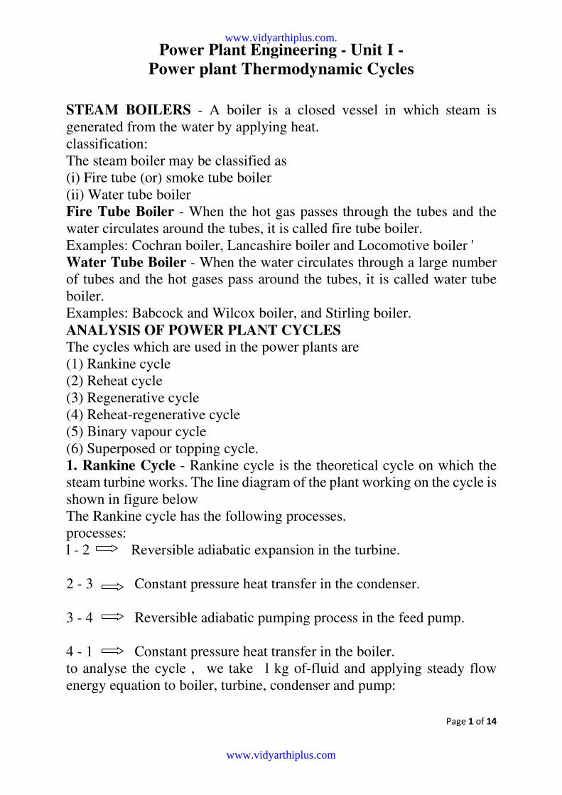
1. Rankine Cycle - Rankine cycle is the theoretical cycle on which the
steam turbine works. The line diagram of the plant working on the cycle is
shown in figure below
The Rankine cycle has the following processes.
processes:
l - 2 Reversible adiabatic expansion in the turbine.
2 - 3 Constant pressure heat transfer in the condenser.
3 - 4 Reversible adiabatic pumping process in the feed pump.
4 - 1 Constant pressure heat transfer in the boiler.
to analyse the cycle , we take l kg of-fluid and applying steady flow
energy equation to boiler, turbine, condenser and pump:
www.vidyarthiplus.com.
www.vidyarthiplus.com
Power Plant Engineering - Unit I -
Power plant Thermodynamic Cycles
Page 2 of 14
1) Boiler (as constant volume) 4
11 ∫+= hQh
411 ∫
−= hhQ , where, Q1 = Heat supplied in boiler
2) for turbine (as constant volume) h1 = WT + h2
WT = h1 - h2, where WT = Turbine work
3) for condenser, 322 ∫
+= hQh
www.vidyarthiplus.com.
www.vidyarthiplus.com
Power Plant Engineering - Unit I -
Power plant Thermodynamic Cycles
Page 3 of 14
322 ∫
−= hhQ , where, Q2 = Heat rejection in condenser
4) for pump 43 ∫∫=+ hWh p
34 ∫∫−= hhWp
Wp = V3(p1 - p2) where Wp = pump work, and V in m3 / kg, p in bar
the efficiency of Rankine cycle is given by
][sup 11 Q
WW
Q
W
pliedheat
Workoutput PTnetRankine
−===η
])(
)()([
sup4
34
1
21
∫
∫∫
−
−−−==
hh
hhhh
pliedheat
WorkoutputRankineη
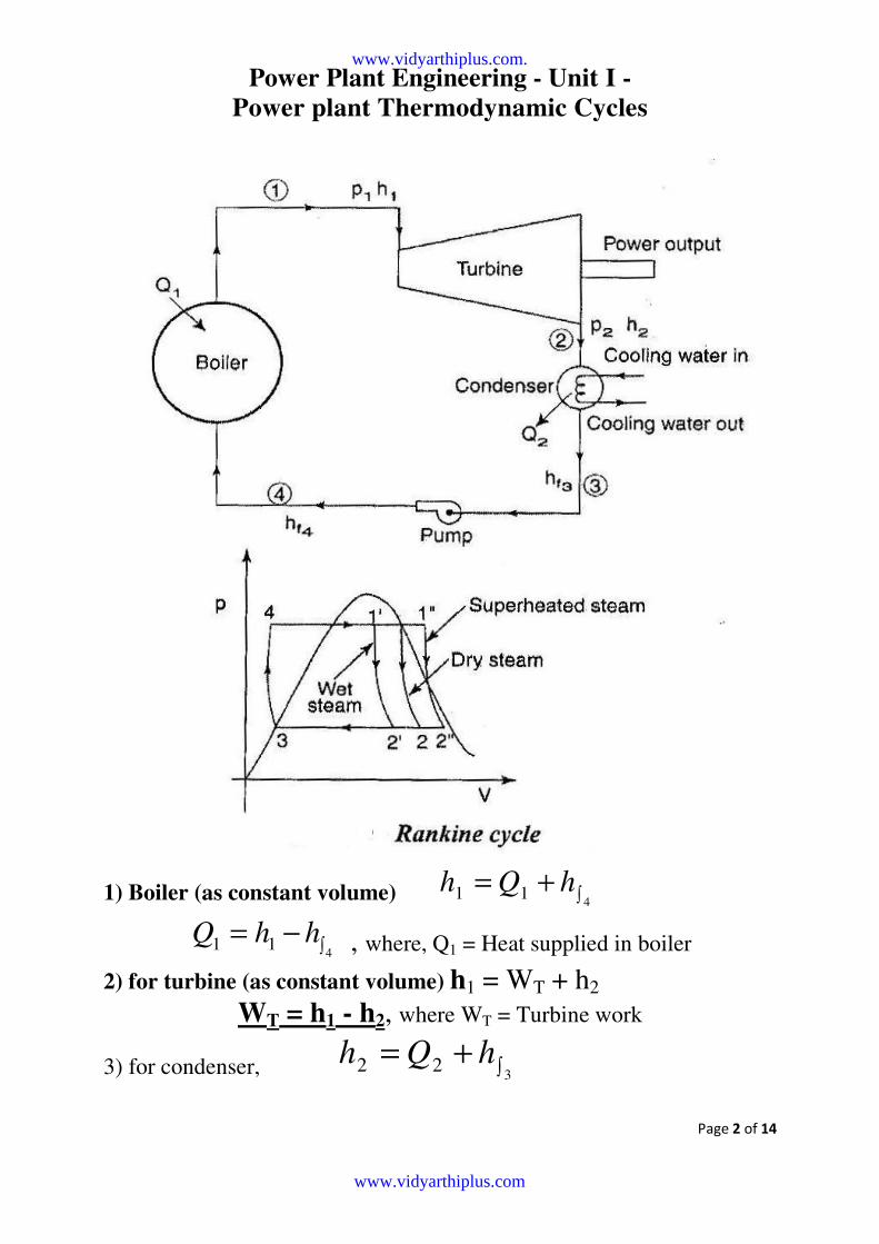
2. Reheat cycle - The efficiency of the ordinary Rankine cycle can be
improved by increasing the pressure and temperature of the steam
entering into the turbine. This is shown in fig below. In reheat cycle, the
steam is extracted from a suitable point in the turbine and is reheated with
the help of flue gases in the boiler furnace.
www.vidyarthiplus.com.
www.vidyarthiplus.com
Power Plant Engineering - Unit I -
Power plant Thermodynamic Cycles
Page 4 of 14
The main purpose of reheating is to increase the dryness fraction of steam
and improve the cycle efficiency by 5%. But the dryness fraction of steam
coming out of turbine should not fall below 0.88. The cost of reheat cycle
is about 5 to 10% more than that of the conventional boilers. By using the
reheat cycle, the specific steam consumption decreases and thermal
efficiency become increases. Normally, the reheat pressure is 20% of the
initial pressure of the steam.
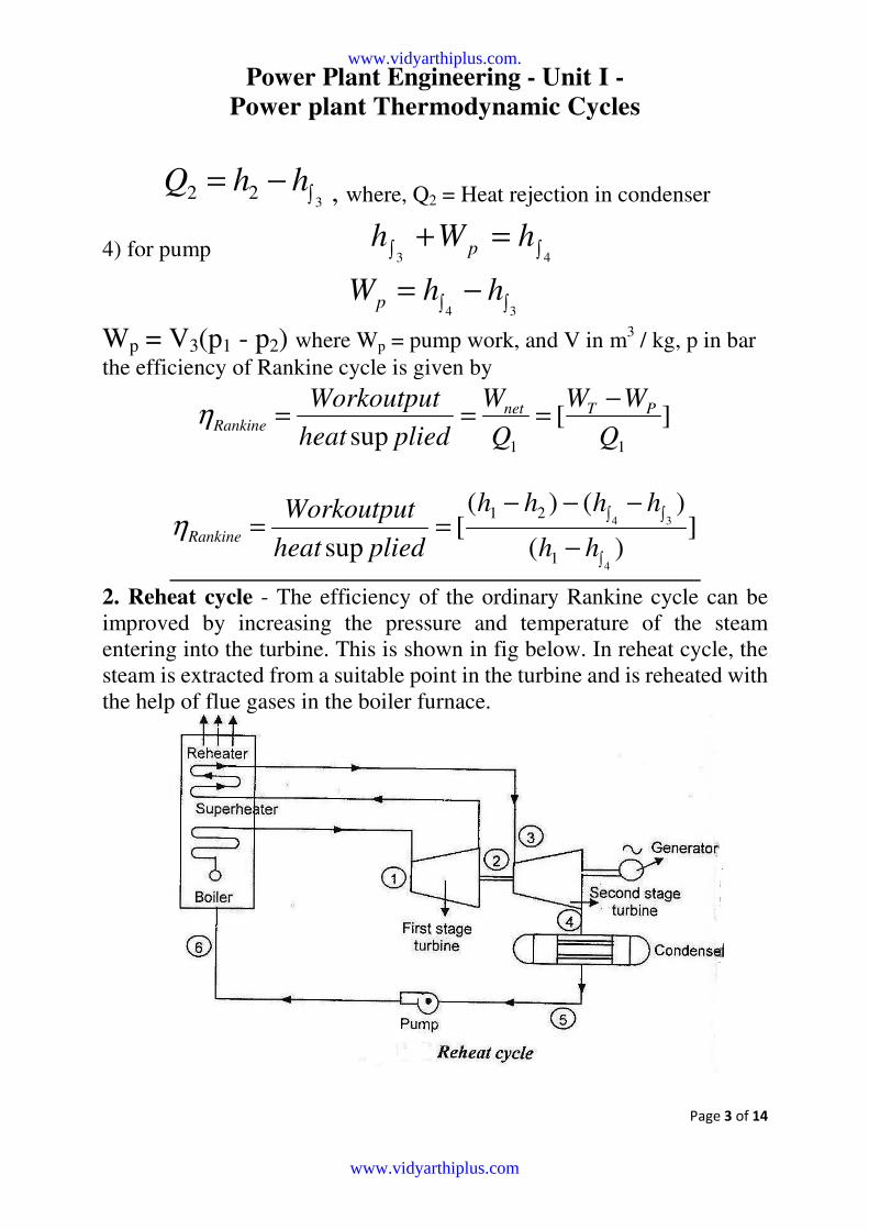
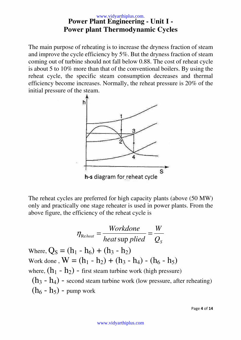
The reheat cycles are preferred for high capacity plants (above (50 MW)
only and practically one stage reheater is used in power plants. From the
above figure, the efficiency of the reheat cycle is
S
heatQ
W
pliedheat
Workdone==
supReη
Where, QS = (h1 - h6) + (h3 - h2)
Work done , W = (h1 - h2) + (h3 - h4) - (h6 - h5)
where, (h1 - h2) - first steam turbine work (high pressure)
(h3 - h4) - second steam turbine work (low pressure, after reheating)
(h6 - h5) - pump work
www.vidyarthiplus.com.
www.vidyarthiplus.com
Power Plant Engineering - Unit I -
Power plant Thermodynamic Cycles
Page 5 of 14
hence, )()(
)()()(
2361
564321
Rehhhh
hhhhhhheat
−+−
−−−+−=η
neglecting pump work , where h6 = h5 ,
)()(
)()(
2361
4321Re
hhhh
hhhhheat
−+−
−+−=η
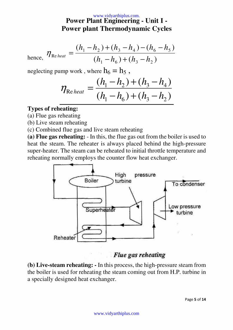
Types of reheating:
(a) Flue gas reheating
(b) Live steam reheating
(c) Combined flue gas and live steam reheating
(a) Flue gas reheating: - In this, the flue gas out from the boiler is used to
heat the steam. The reheater is always placed behind the high-pressure
super-heater. The steam can be reheated to initial throttle temperature and
reheating normally employs the counter flow heat exchanger.
(b) Live-steam reheating: - In this process, the high-pressure steam from
the boiler is used for reheating the steam coming out from H.P. turbine in
a specially designed heat exchanger.
www.vidyarthiplus.com.
www.vidyarthiplus.com
Power Plant Engineering - Unit I -
Power plant Thermodynamic Cycles
Page 6 of 14
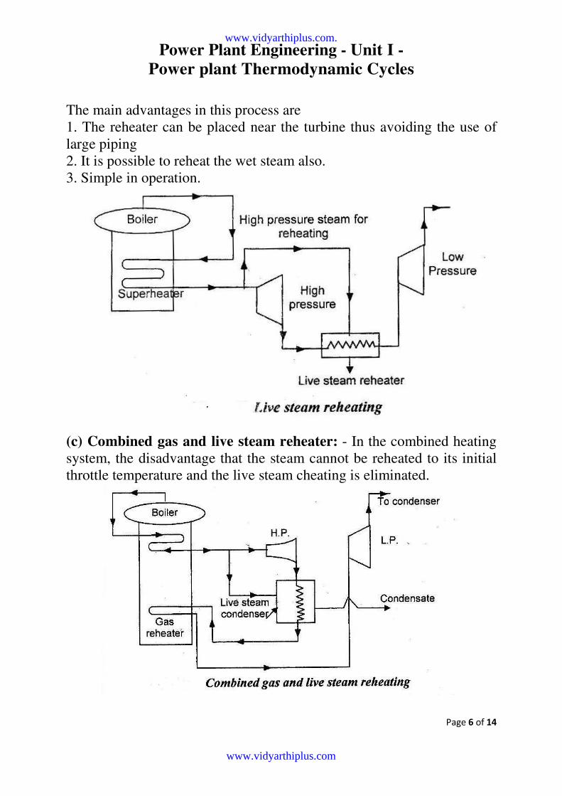
The main advantages in this process are
1. The reheater can be placed near the turbine thus avoiding the use of
large piping
2. It is possible to reheat the wet steam also.
3. Simple in operation.
(c) Combined gas and live steam reheater: - In the combined heating
system, the disadvantage that the steam cannot be reheated to its initial
throttle temperature and the live steam cheating is eliminated.
www.vidyarthiplus.com.
www.vidyarthiplus.com
Power Plant Engineering - Unit I -
Power plant Thermodynamic Cycles
Page 7 of 14
The steam coming out from the H.P. turbine is first passed through the
live steam reheater and then to gas reheater. It is clearly shown in the fig.
above. After reheating in the gas reheater, the steam is put through the
low-pressure turbine. Initially, the. steam from the boiler is superheated in
the superheater.
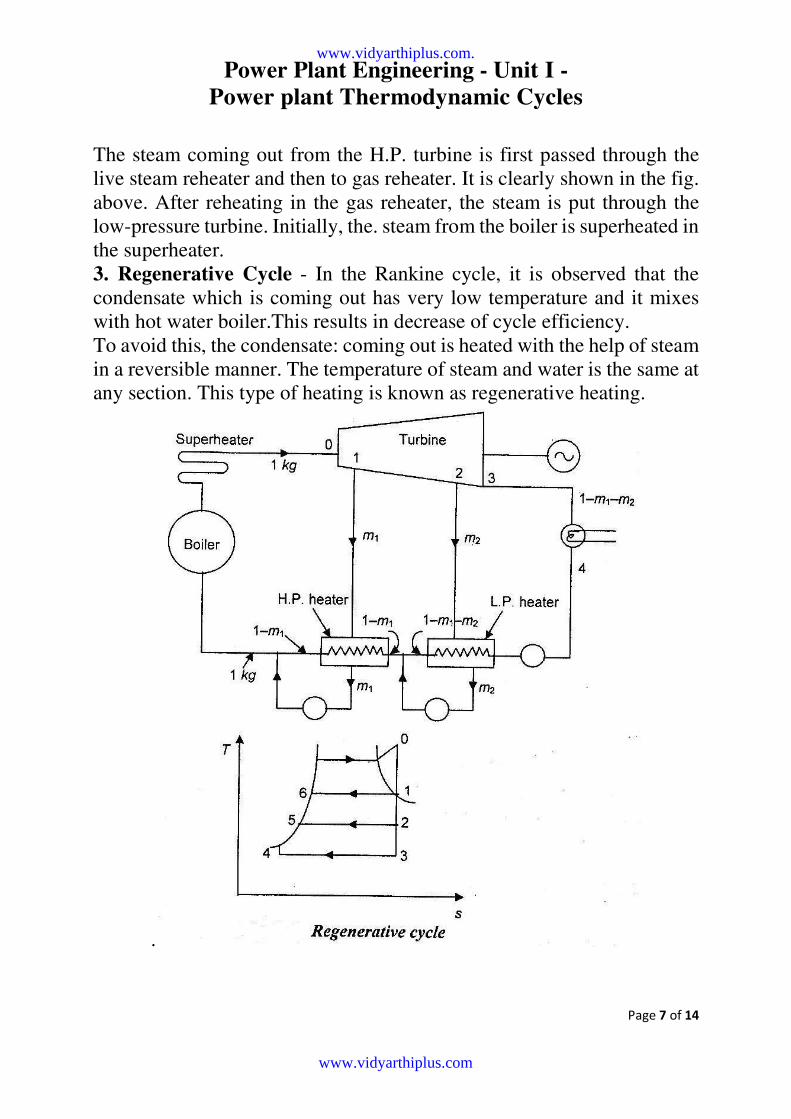
3. Regenerative Cycle - In the Rankine cycle, it is observed that the
condensate which is coming out has very low temperature and it mixes
with hot water boiler.This results in decrease of cycle efficiency.
To avoid this, the condensate: coming out is heated with the help of steam
in a reversible manner. The temperature of steam and water is the same at
any section. This type of heating is known as regenerative heating.
.
www.vidyarthiplus.com.
www.vidyarthiplus.com
Power Plant Engineering - Unit I -
Power plant Thermodynamic Cycles
Page 8 of 14
Fig above shows a layout of a condensing steam power plant in which a
surface condenser is used to condense all the steam that is not extracted
for feed water heating. The boiler is equipped With : superheater and
turbine is double extracting type. '
The conditions of steam bled for each heater are so selected that the
temperature of saturated steam will be 4 to lO*C higher than the final
Condensate temperature.
Let. m1 = kg of high pressure steam per kg of steam flow
Let. m2 = kg of low pressure steam extracted per kg of steam flow
(1-m1-m2) = kg of steam entering condenser per kg of steam flow.
Heat supplied externally in the cycle = )(6
0 ∫− hh
Isentropic work done,
= (h0 - h1 ) + (1-m1) (h1 - h2) + (1-m1 - m2) (h2 - h3)
thermal efficiency = pliedheat
Workdone
sup
)(
))(1())(1()(
60
322121110
∫−
−−−+−−+−=
hh
hhmmhhmhh
where, 5
56
1
1
∫
∫∫
−
−=
hh
hhm
and )(
))(1(
3
35
2
1
2
∫
∫∫
−
−−=
hh
hhmm
Advantages of regenerative cycle:
1 . The thermal stresses set up in the boiler be minimized.
2. The heating process in the boiler tends to become reversible.
3. Heat rate is reduced.
4, A small size condenser is required.
Disadvantages: 1 . Due to addition of heaters, greater maintenance is required,
2. The plant becomes more complicated.
3. Large capacity boiler is required.
www.vidyarthiplus.com.
www.vidyarthiplus.com
Power Plant Engineering - Unit I -
Power plant Thermodynamic Cycles
Page 9 of 14
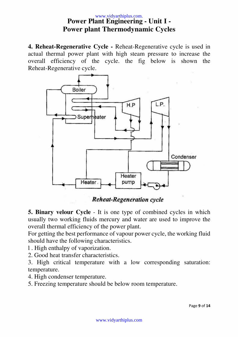
4. Reheat-Regenerative Cycle - Reheat-Regenerative cycle is used in
actual thermal power plant with high steam pressure to increase the
overall efficiency of the cycle. the fig below is shown the
Reheat-Regenerative cycle.
5. Binary velour Cycle - It is one type of combined cycles in which
usually two working fluids mercury and water are used to improve the
overall thermal efficiency of the power plant.
For getting the best performance of vapour power cycle, the working fluid
should have the following characteristics.
l . High enthalpy of vaporization.
2. Good heat transfer characteristics.
3. High critical temperature with a low corresponding saturation:
temperature.
4. High condenser temperature.
5. Freezing temperature should be below room temperature.
www.vidyarthiplus.com.
www.vidyarthiplus.com
Power Plant Engineering - Unit I -
Power plant Thermodynamic Cycles
Page 10 of 14
www.vidyarthiplus.com.
www.vidyarthiplus.com
Power Plant Engineering - Unit I -
Power plant Thermodynamic Cycles
Page 11 of 14
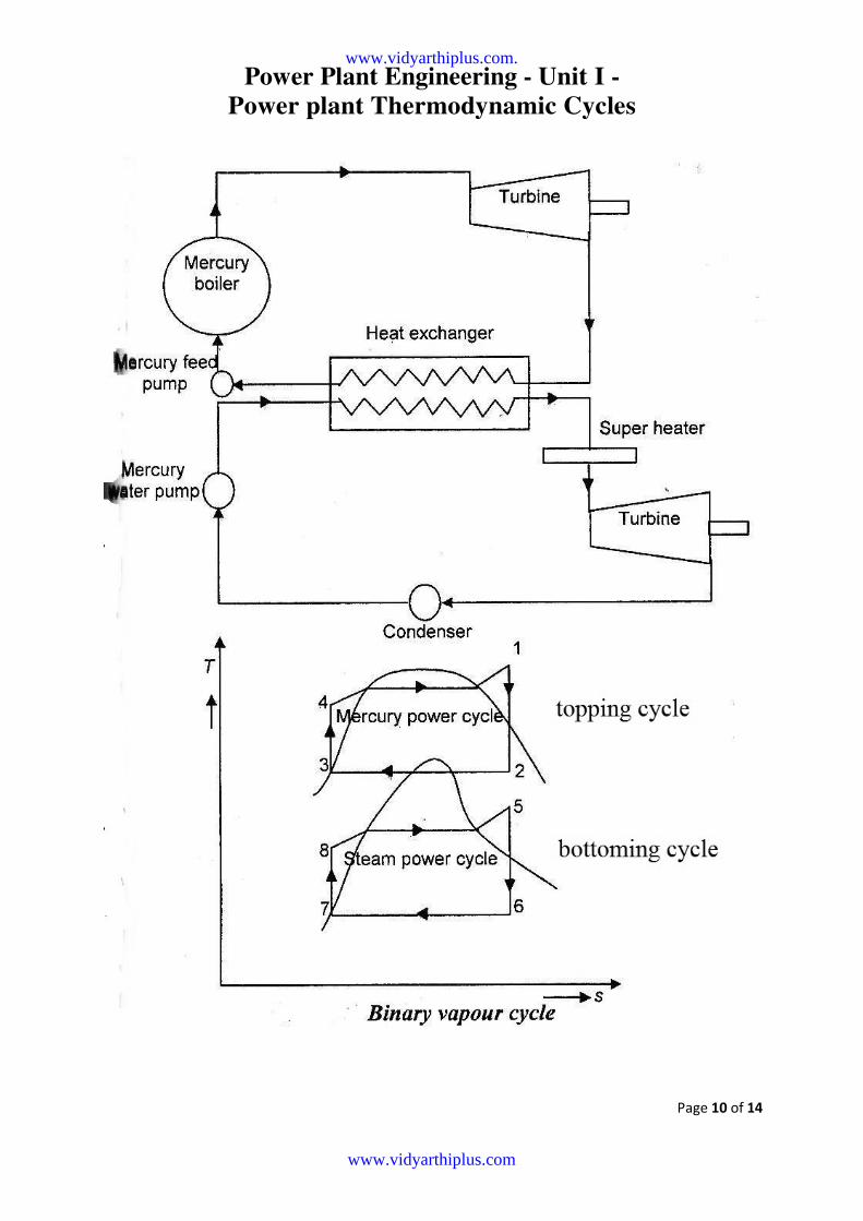
The cycle has one high temperature region and one low temperature
region. This is called a binary vapour cycle. In this cycle, the condenser pf
the high temperature cycle called topping cycle, and the low temperature
cycle termed as bottoming cycle.
1. Topping cycle: - In the above figure,
the process 1-2 shows the expansion of the mercury vapour in the mercury
turbine.
Process 2-3 represents the condensation if the mercury in the condenser or
heat exchanger where the heat exchanges from mercury vapour to water.
Process 3-4 shows the pumping work
process 4-1 represents heating of the liquid mercury to the saturation
temperature.
Bottoming cycle: -The heat removed from the mercury is used for
heating the liquid. it is shown by the process 8-9. The process 9-5
represents the overheated steam in the superheater.
The super heated steam is expanded in the steam turbine and then
condensed in condenser. It is shown by the curve 5-6 and 6-7. The process
7-8 represents the pumping process of the feed water in feed pump.
Let m = Mass of mercury in the mercury cycle/kg of steam circulated.
Heat supplied (Qs) = m x (h1 - h4) + (h5 - h9)
Work done by mercury turbine/kg of steam
)( 21 hhGeneratedWMT −=
Work done by the steam turbine//kg of steam generated
)( 61 hhWST −=
Heat Rejected = QR = (h6 - h7)
total work done in Binary cycle Sm TTT WWW +=
Pump work Wp = m(h4-h3) + (h8-h7)
www.vidyarthiplus.com.
www.vidyarthiplus.com
Power Plant Engineering - Unit I -
Power plant Thermodynamic Cycles
Page 12 of 14
Overall efficiency of the Binary cycle , S
STBinary
Q
WW +=η
specific steam rate (SSR) kwhrkg
WW PT
/3600
−=
Thermal efficiency of the mercury cycle
11*
*
h
W
hm
Wmmm TT
Binary ==η
Thermal efficiency of the mercury cycle , 85 hh
WTsBinary
−==η
The value of m can be determined from energy balance equation
m(h2-h3)= (h9-h8)
mass flow rate of mercury required /kg of steam flow rate,
32
89
hh
hhm
−
−=
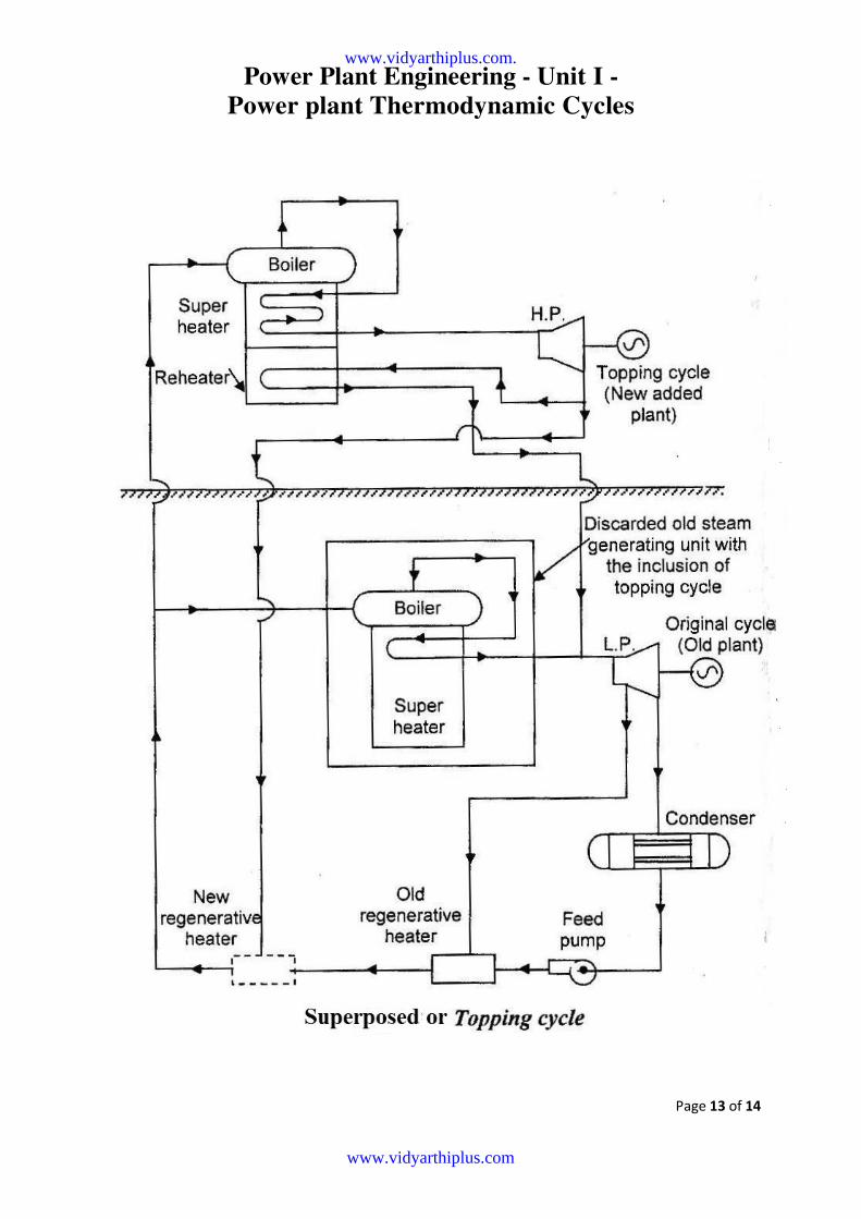
3. superposed or Topping cycle: - Whenever the demand increases, the
capacity of the existing thermal power plant may be expanded either by
increasing the capacity of existing plant or by purchasing additional
equipment.
Similar to that the superposed or topping cycle, it is included to the
existing unit to increase the power demand. The arrangement is shown
in fig below
By supplying the sufficient steam by the superposed unit into original
plant header, the excellent qualities of existing turbines are retained. The
economics of plant operation are increased by the help of topping cycle.
www.vidyarthiplus.com.
www.vidyarthiplus.com
Power Plant Engineering - Unit I -
Power plant Thermodynamic Cycles
Page 13 of 14
www.vidyarthiplus.com.
www.vidyarthiplus.com
Power Plant Engineering - Unit I -
Power plant Thermodynamic Cycles
Page 14 of 14
Modern Trends in Power Plant Cycle improvement - There are some
drawbacks with the steam cycles while using steam as the working fluid.
The maximum temperature of steam cycles is about 600*C while the
critical temperature of steam is 375*C which requires large super heating
and the use of reheat is necessary.
The reheater tubes are costly. So, the use of two reheats is recommended.
The desirable characteristics of the working fluid in a vapour power cycle
to obtain the best thermal efficiency is
1. The freezing point of the fluid should be below the room temperature.
2.Saturation pressure at the temperature of heat rejection should be above
the atmospheric pressure., 3. Specific heat of liquid should be small. 4.
The fluids should have high critical temperature. 5. The fluid should be
chemically stable. 6. The moisture should not appear during expansion.
No single fluid can meet all the requirements as mentioned above.
So, the binary vapour cycles are used. Combining two Rankine cycles in
series also increase the efficiency of the cycle.
There is a lot of scope for improving cycle efficiency and achieving fuel
economy using multi-fluid coupled cycles and utilization of different
working fluids is having different temperature range. In power cycle, the
steam temperature does not exceed 600*C but the furnace temperature is
l300*C. 'So, there is a great thermal irreversibility and a decrease of
availability because of heat transfer from combustion gases to steam
through a large temperature difference.
The high fuel to electricity can be achieved by superposing a high
temperature power plant as a topping unit to the steam plant. The
combined plants are the following 1. Gas turbine - Steam turbine plant, 2.
MHD-steam plant, 3. Thermionic-steam plant,
4. Thermoelectric-steam plant.
(The working principle of above said plants has been already explained In
coal-based combined cycle plants, the following two dominate j
technologies are used. They are (1) Pressurized fluid red bed combustion
system, and (2) Integrated Gasification combined cycle.
It is to reduce the concentration of participates in products of combustion
before entering the gas turbine.
www.vidyarthiplus.com.
www.vidyarthiplus.com
Related Documents