Vision & Motion – The frame throughput is improved by leveraging hardware video encoding to calculate optic flow using H.264. Motion data is segmented into foreground and background classes (Figure 4) to provide an additional input for to the sensor fusion system. Control & Tuning – In autonomous flight, Pl controllers are used to keep the heading, altitude and speed of the blimp constant relative to the target. The controller step responses were tuned during test flights (Table 1). Conclusions – This blimp provides a hardware and software platform to demonstrate autonomous station keeping behaviour without relying on additional ground-based equipment. Future work will now refine the vision system and improve control systems reliability. Untethered Autonomous Flight of an Indoor Blimp Andrew Mathieson Supervisor: Toby Breckon School of Engineering & Computer Sciences, Durham University Abstract – A prototype autonomous airship was developed and tested indoors (Figure 1). Until now, autonomous blimps have utilised additional equipment on the ground to calculate their position. This project instead uses visual and inertia sensing to perform all processing on board. Hardware – Low-cost commercial hardware components were integrated into the blimp payload. The key objectives for component selection were weight minimisation and software availability. The hardware comprises an Inertial Measurement Unit (IMU), Pulse Width Modulated (PWM) servo outputs and optically isolated motor drivers (Figure 2). Software – Estimates blimp pose relative to a chessboard target using the camera, and fuses camera pose estimates with data from the IMU. Software is divided into four concurrent threads (Figure 3) and runs on a Raspberry Pi 2. MEng Research & Development Project April 2015 Figure 1 – Blimp in flight Figure 2 – Hardware components Figure 3 – Software architecture Figure 4 – Captured frame and HSV representation of motion Zeigler-Nichols predicted Harriot/Nyquist predicted value found testing 5.7 (underestimate) 19 (overestimate) 10 (Achieves good control) Table 1 – Proportional gain ( ) tuning: Comparison of results from two analytical methods with experimental results

Welcome message from author
This document is posted to help you gain knowledge. Please leave a comment to let me know what you think about it! Share it to your friends and learn new things together.
Transcript
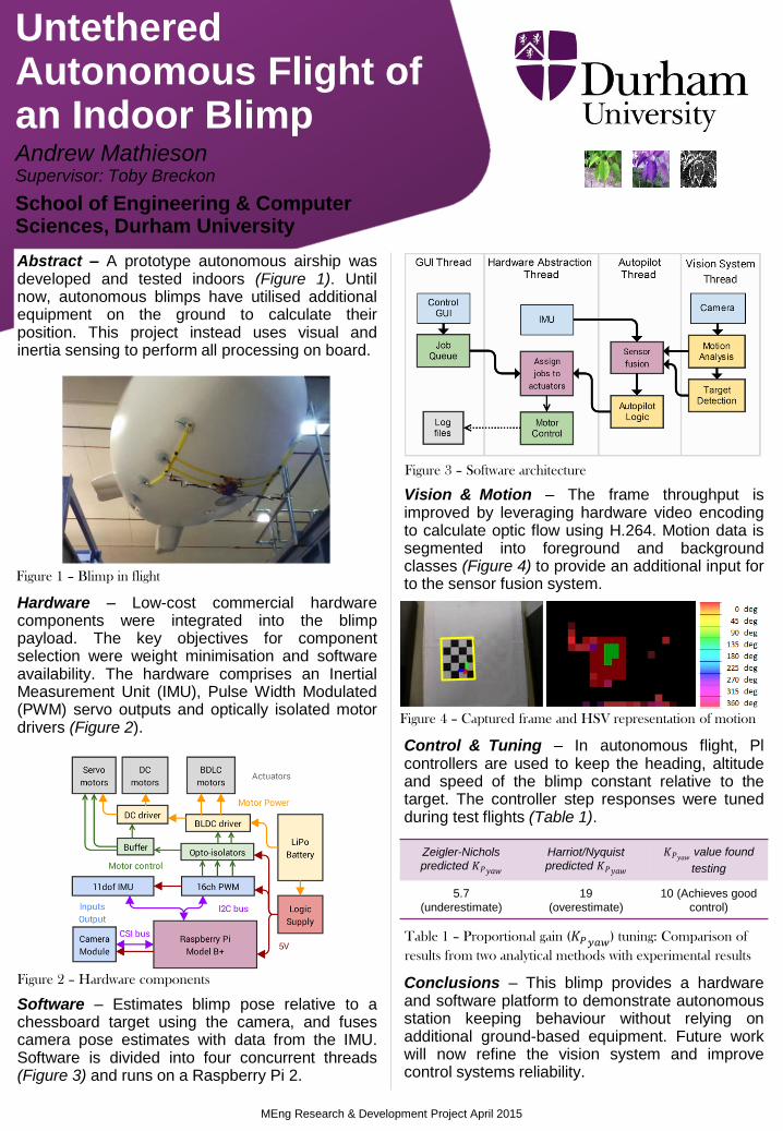
Visionᅠ&ᅠMotion – The frame throughput is improved by leveraging hardware video encoding to calculate optic flow using H.264. Motion data is segmented into foreground and background classes (Figure 4) to provide an additional input for to the sensor fusion system.
Controlᅠ&ᅠTuning – In autonomous flight, Pl controllers are used to keep the heading, altitude and speed of the blimp constant relative to the target. The controller step responses were tuned during test flights (Table 1).
Conclusions – This blimp provides a hardware and software platform to demonstrate autonomous station keeping behaviour without relying on additional ground-based equipment. Future work will now refine the vision system and improve control systems reliability.
Untethered Autonomous Flight of an Indoor Blimp
Andrew Mathieson Supervisor: Toby Breckon
School of Engineering & Computer Sciences, Durham University
Abstract – A prototype autonomous airship was developed and tested indoors (Figure 1). Until now, autonomous blimps have utilised additional equipment on the ground to calculate their position. This project instead uses visual and inertia sensing to perform all processing on board.
Hardware – Low-cost commercial hardware components were integrated into the blimp payload. The key objectives for component selection were weight minimisation and software availability. The hardware comprises an Inertial Measurement Unit (IMU), Pulse Width Modulated (PWM) servo outputs and optically isolated motor drivers (Figure 2).
Software – Estimates blimp pose relative to a chessboard target using the camera, and fuses camera pose estimates with data from the IMU. Software is divided into four concurrent threads (Figure 3) and runs on a Raspberry Pi 2.
MEng Research & Development Project April 2015
Figure 1 – Blimp in flight
Figure 2 – Hardware components
Figure 3 – Software architecture
Figure 4 – Captured frame and HSV representation of motion
Zeigler-Nichols
predicted 𝐾𝑃𝑦𝑎𝑤
Harriot/Nyquist
predicted 𝐾𝑃𝑦𝑎𝑤
𝐾𝑃𝑦𝑎𝑤 value found
testing
5.7
(underestimate)
19
(overestimate)
10 (Achieves good
control)
Table 1 – Proportional gain (𝐾𝑃𝑦𝑎𝑤) tuning: Comparison of
results from two analytical methods with experimental results
Related Documents


![05-04 Poster (FA-10) [Converted] copy](https://static.cupdf.com/doc/110x72/568bd9c21a28ab2034a83621/05-04-poster-fa-10-converted-copy.jpg)

