200708 (V3.1) Hägele GmbH Am Niederfeld 13 D-73614 Schorndorf Service: +49 (0)7181-96988-31 [email protected] Cleanfix North America Ltd. 250 Wright Blvd Stratford On, N4Z 1H3 Service: Phone: 519-275-2808 www.cleanfix.org PNEUMATIC REVERSIBLE FANS C162 / C200 / C220 / C222 / C225 / C250 / C252 / C300 Installation Instructions

Welcome message from author
This document is posted to help you gain knowledge. Please leave a comment to let me know what you think about it! Share it to your friends and learn new things together.
Transcript
200708 (V3.1)
Hägele GmbH Am Niederfeld 13 D-73614 Schorndorf
Service: +49 (0)7181-96988-31 [email protected]
Cleanfix North America Ltd. 250 Wright Blvd Stratford On, N4Z 1H3
Service: Phone: 519-275-2808 www.cleanfix.org
PNEUMATIC REVERSIBLE FANS
C162 / C200 / C220 / C222 / C225 / C250 / C252 / C300
Installation Instructions

200708 (V3.1)
(V3.1) 200708
PNEUMATIC REVERSIBLE FANS EN
Hägele GmbH, Am Niederfeld 13, 73614 Schorndorf, Service:+49 (0)7181 96988-0, Mail: [email protected] 1
Content 1 General information.................................................................................................................................... 1
2 Tools ......................................................................................................................................................... 1
3 Mounting guidelines ................................................................................................................................... 2
3.1 Removal of the original manufactures fan ............................................................................................ 2
3.2 Installation of the CLEANFIX® Fan ....................................................................................................... 2
Installation Flange .......................................................................................................................... 2 3.2.1
Installation pneumatic hose ............................................................................................................ 3 3.2.2
Installation fan ............................................................................................................................... 4 3.2.3
4 Electrical guidelines .................................................................................................................................... 7
A: Cleanfix Valve / For vehicles with a compressed air system ...................................................................... 7
B: Cleanfix Valve Unit with Minitimer or Multitimer / For vehicles with a compressed air system ...................... 8
C: Cleanfix Standard Compressor Unit ......................................................................................................... 9
D: Cleanfix Control Unit with Minitimer or Multitimer................................................................................... 10
E: Cleanfix E-Box with Multitimer .............................................................................................................. 11
5 Troubleshooting ....................................................................................................................................... 12
1 General information NOTE:
The following instructions describe the installation of the pneumatic CLEANFIX® reversible fans (C162 / C200 / C220 / C222 / C225 / C250 / C252 / C300).
NOTE: Since we are not included in technical service updates from the manufacturer, it may be necessary to make adjustments when installing this kit. Installation and modifications (move radiator, trim shroud) costs are not the responsibility of Cleanfix. Damage costs due to improper installation are not the responsibility of Cleanfix.
WARNING: A vibration damper is essential when installing the CLEANFIX® reversible fans directly on the crankshaft or when driven by a spur gear!
WARNING: Only operate the reversing feature of CLEANFIX® reversible fans within the machine manufacturers recommended operating temperature range in order to avoid engine overheating!
WARNING: Only operate the reversing feature of CLEANFIX® reversible fans in a safe outside location!
WARNING: Observe all applicable safety regulations while working on, around or under a machine!
2 Tools - Magnetic or clamp type dial gauge
- Torque key
- Electric drill
- Metric step drill (16mm and 22mm)
- Standard hand tools
- Grease
EN 200708 (V3.1)
PNEUMATIC REVERSIBLE FANS
2 Hägele GmbH, Am Niederfeld 13, 73614 Schorndorf, Service:+49 (0)7181 96988-0, Mail: [email protected]
3 Mounting guidelines 3.1 Removal of the original manufactures fan
WARNING: Turn off engine and allow to cool, retain ignition key and disconnect battery from the machine.
Remove the original manufactures fan (refer to the manufacturer's manual). 3.2 Installation of the CLEANFIX® Fan
Installation Flange 3.2.1
1.
2.
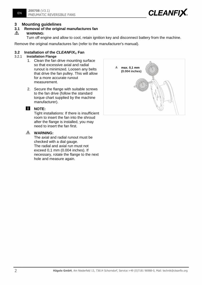
Clean the fan drive mounting surface so that excessive axial and radial runout is minimized. Loosen any belts that drive the fan pulley. This will allow for a more accurate runout measurement.
Secure the flange with suitable screws to the fan drive (follow the standard torque chart supplied by the machine manufacturer).
NOTE: Tight installations: If there is insufficient room to insert the fan into the shroud after the flange is installed, you may need to insert the fan first.
WARNING: The axial and radial runout must be checked with a dial gauge. The radial and axial run must not exceed 0,1 mm (0.004 inches). If necessary, rotate the flange to the next hole and measure again.
max. 0,1 mm
(0.004 inches)
(V3.1) 200708
PNEUMATIC REVERSIBLE FANS EN
Hägele GmbH, Am Niederfeld 13, 73614 Schorndorf, Service:+49 (0)7181 96988-0, Mail: [email protected] 3
Installation pneumatic hose 3.2.2
1.
2.
3.
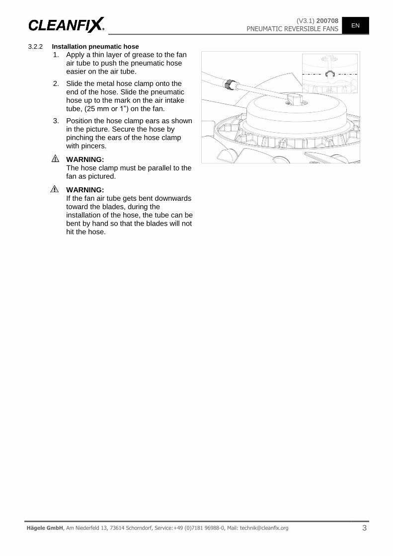
Apply a thin layer of grease to the fan air tube to push the pneumatic hose easier on the air tube.
Slide the metal hose clamp onto the end of the hose. Slide the pneumatic hose up to the mark on the air intake tube, (25 mm or 1”) on the fan.
Position the hose clamp ears as shown in the picture. Secure the hose by pinching the ears of the hose clamp with pincers.
WARNING: The hose clamp must be parallel to the fan as pictured.
WARNING: If the fan air tube gets bent downwards toward the blades, during the installation of the hose, the tube can be bent by hand so that the blades will not hit the hose.
EN 200708 (V3.1)
PNEUMATIC REVERSIBLE FANS
4 Hägele GmbH, Am Niederfeld 13, 73614 Schorndorf, Service:+49 (0)7181 96988-0, Mail: [email protected]
Installation fan 3.2.3
1.
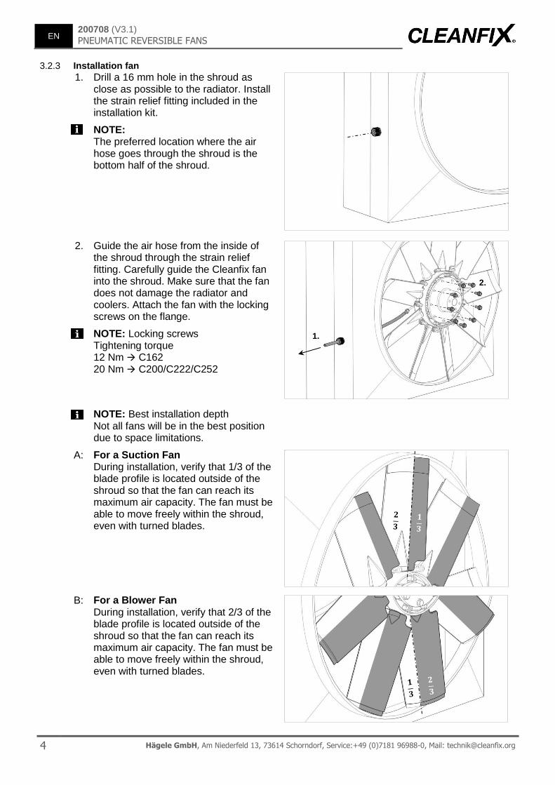
Drill a 16 mm hole in the shroud as close as possible to the radiator. Install the strain relief fitting included in the installation kit.
NOTE: The preferred location where the air hose goes through the shroud is the bottom half of the shroud.
2.
Guide the air hose from the inside of the shroud through the strain relief fitting. Carefully guide the Cleanfix fan into the shroud. Make sure that the fan does not damage the radiator and coolers. Attach the fan with the locking screws on the flange.
NOTE: Locking screws Tightening torque 12 Nm C162 20 Nm C200/C222/C252
NOTE: Best installation depth Not all fans will be in the best position due to space limitations.
A: For a Suction Fan During installation, verify that 1/3 of the blade profile is located outside of the shroud so that the fan can reach its maximum air capacity. The fan must be able to move freely within the shroud, even with turned blades.
B: For a Blower Fan During installation, verify that 2/3 of the blade profile is located outside of the shroud so that the fan can reach its maximum air capacity. The fan must be able to move freely within the shroud, even with turned blades.
1.
2.
(V3.1) 200708
PNEUMATIC REVERSIBLE FANS EN
Hägele GmbH, Am Niederfeld 13, 73614 Schorndorf, Service:+49 (0)7181 96988-0, Mail: [email protected] 5
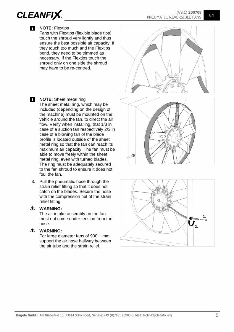
NOTE: Flextips Fans with Flextips (flexible blade tips) touch the shroud very lightly and thus ensure the best possible air capacity. If they touch too much and the Flextips bend, they need to be trimmed as necessary. If the Flextips touch the shroud only on one side the shroud may have to be re-centred.
NOTE: Sheet metal ring The sheet metal ring, which may be included (depending on the design of the machine) must be mounted on the vehicle around the fan, to direct the air flow. Verify when installing, that 1/3 in case of a suction fan respectively 2/3 in case of a blowing fan of the blade profile is located outside of the sheet metal ring so that the fan can reach its maximum air capacity. The fan must be able to move freely within the sheet metal ring, even with turned blades. The ring must be adequately secured to the fan shroud to ensure it does not foul the fan.
3.
Pull the pneumatic hose through the strain relief fitting so that it does not catch on the blades. Secure the hose with the compression nut of the strain relief fitting.
WARNING: The air intake assembly on the fan must not come under tension from the hose.
WARNING: For large diameter fans of 900 + mm, support the air hose halfway between the air tube and the strain relief.
1.
2.
EN 200708 (V3.1)
PNEUMATIC REVERSIBLE FANS
6 Hägele GmbH, Am Niederfeld 13, 73614 Schorndorf, Service:+49 (0)7181 96988-0, Mail: [email protected]
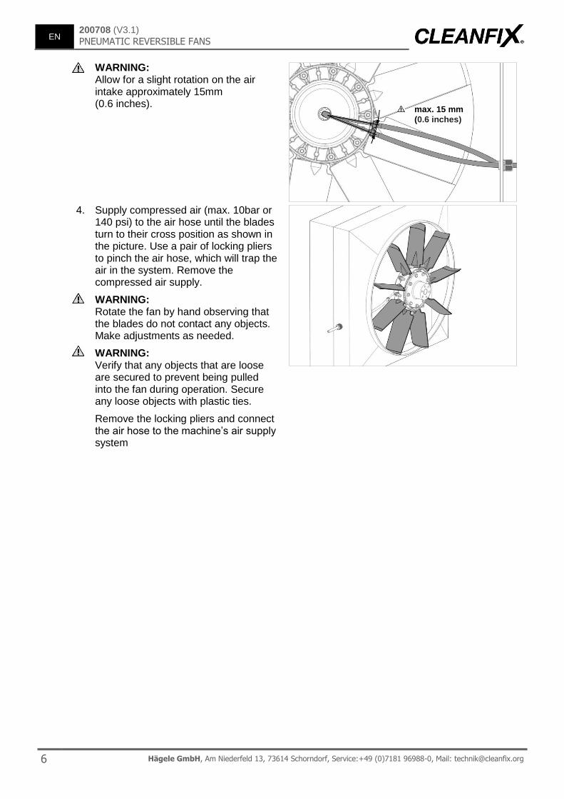
WARNING: Allow for a slight rotation on the air intake approximately 15mm (0.6 inches).
4.
Supply compressed air (max. 10bar or 140 psi) to the air hose until the blades turn to their cross position as shown in the picture. Use a pair of locking pliers to pinch the air hose, which will trap the air in the system. Remove the compressed air supply.
WARNING: Rotate the fan by hand observing that the blades do not contact any objects. Make adjustments as needed.
WARNING: Verify that any objects that are loose are secured to prevent being pulled into the fan during operation. Secure any loose objects with plastic ties.
Remove the locking pliers and connect the air hose to the machine’s air supply system
max. 15 mm
(0.6 inches)
(V3.1) 200708
PNEUMATIC REVERSIBLE FANS EN
Hägele GmbH, Am Niederfeld 13, 73614 Schorndorf, Service:+49 (0)7181 96988-0, Mail: [email protected] 7
4 Electrical guidelines
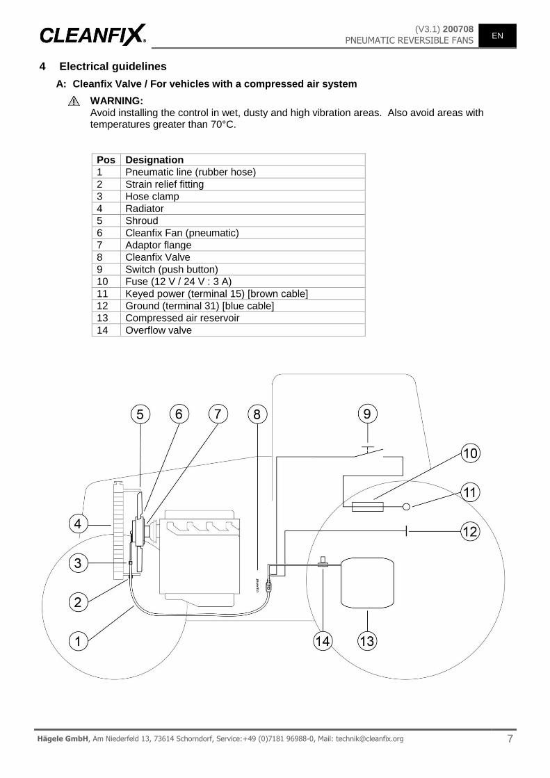
A: Cleanfix Valve / For vehicles with a compressed air system
WARNING: Avoid installing the control in wet, dusty and high vibration areas. Also avoid areas with temperatures greater than 70°C.
Pos Designation
1 Pneumatic line (rubber hose)
2 Strain relief fitting
3 Hose clamp
4 Radiator
5 Shroud
6 Cleanfix Fan (pneumatic)
7 Adaptor flange
8 Cleanfix Valve
9 Switch (push button)
10 Fuse (12 V / 24 V : 3 A)
11 Keyed power (terminal 15) [brown cable]
12 Ground (terminal 31) [blue cable]
13 Compressed air reservoir
14 Overflow valve
EN 200708 (V3.1)
PNEUMATIC REVERSIBLE FANS
8 Hägele GmbH, Am Niederfeld 13, 73614 Schorndorf, Service:+49 (0)7181 96988-0, Mail: [email protected]
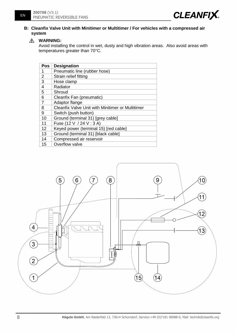
B: Cleanfix Valve Unit with Minitimer or Multitimer / For vehicles with a compressed air system
WARNING: Avoid installing the control in wet, dusty and high vibration areas. Also avoid areas with temperatures greater than 70°C.
Pos Designation
1 Pneumatic line (rubber hose)
2 Strain relief fitting
3 Hose clamp
4 Radiator
5 Shroud
6 Cleanfix Fan (pneumatic)
7 Adaptor flange
8 Cleanfix Valve Unit with Minitimer or Multitimer
9 Switch (push button)
10 Ground (terminal 31) [grey cable]
11 Fuse (12 V / 24 V : 3 A)
12 Keyed power (terminal 15) [red cable]
13 Ground (terminal 31) [black cable]
14 Compressed air reservoir
15 Overflow valve
(V3.1) 200708
PNEUMATIC REVERSIBLE FANS EN
Hägele GmbH, Am Niederfeld 13, 73614 Schorndorf, Service:+49 (0)7181 96988-0, Mail: [email protected] 9
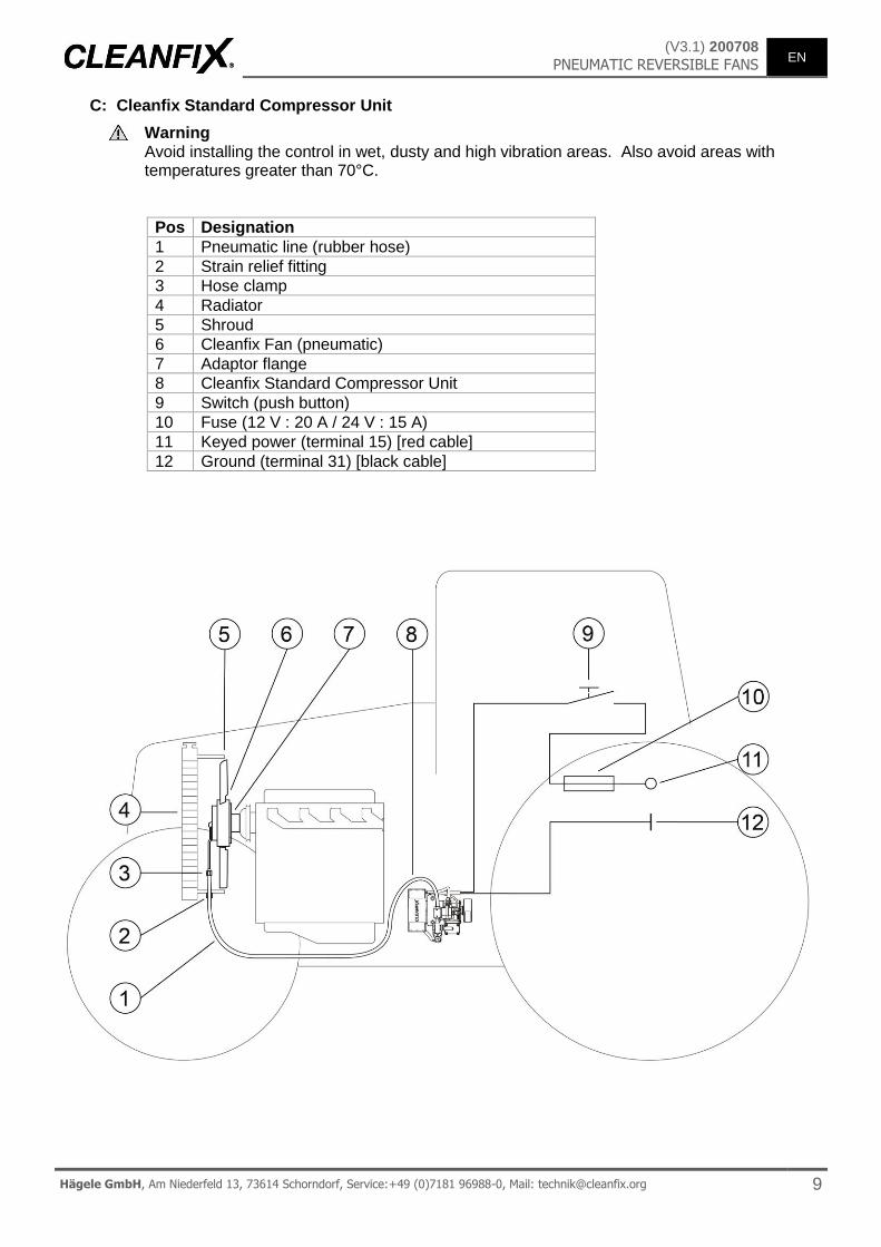
C: Cleanfix Standard Compressor Unit
Warning Avoid installing the control in wet, dusty and high vibration areas. Also avoid areas with temperatures greater than 70°C.
Pos Designation
1 Pneumatic line (rubber hose)
2 Strain relief fitting
3 Hose clamp
4 Radiator
5 Shroud
6 Cleanfix Fan (pneumatic)
7 Adaptor flange
8 Cleanfix Standard Compressor Unit
9 Switch (push button)
10 Fuse (12 V : 20 A / 24 V : 15 A)
11 Keyed power (terminal 15) [red cable]
12 Ground (terminal 31) [black cable]
EN 200708 (V3.1)
PNEUMATIC REVERSIBLE FANS
10 Hägele GmbH, Am Niederfeld 13, 73614 Schorndorf, Service:+49 (0)7181 96988-0, Mail: [email protected]
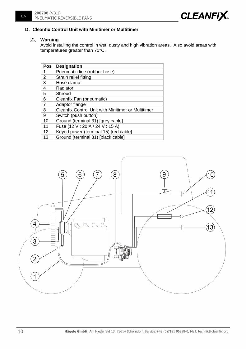
D: Cleanfix Control Unit with Minitimer or Multitimer
Warning Avoid installing the control in wet, dusty and high vibration areas. Also avoid areas with temperatures greater than 70°C.
Pos Designation
1 Pneumatic line (rubber hose)
2 Strain relief fitting
3 Hose clamp
4 Radiator
5 Shroud
6 Cleanfix Fan (pneumatic)
7 Adaptor flange
8 Cleanfix Control Unit with Minitimer or Multitimer
9 Switch (push button)
10 Ground (terminal 31) [grey cable]
11 Fuse (12 V : 20 A / 24 V : 15 A)
12 Keyed power (terminal 15) [red cable]
13 Ground (terminal 31) [black cable]
(V3.1) 200708
PNEUMATIC REVERSIBLE FANS EN
Hägele GmbH, Am Niederfeld 13, 73614 Schorndorf, Service:+49 (0)7181 96988-0, Mail: [email protected] 11
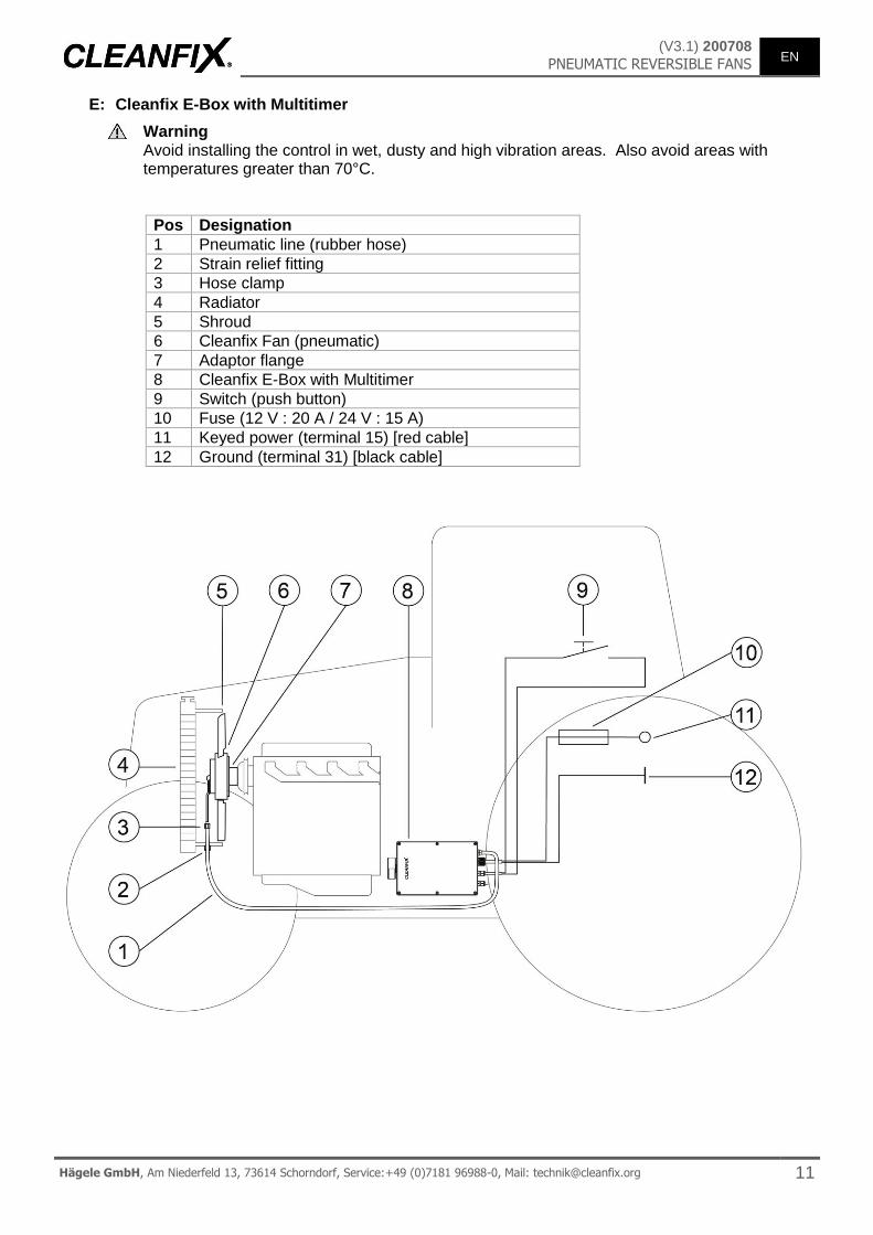
E: Cleanfix E-Box with Multitimer
Warning Avoid installing the control in wet, dusty and high vibration areas. Also avoid areas with temperatures greater than 70°C.
Pos Designation
1 Pneumatic line (rubber hose)
2 Strain relief fitting
3 Hose clamp
4 Radiator
5 Shroud
6 Cleanfix Fan (pneumatic)
7 Adaptor flange
8 Cleanfix E-Box with Multitimer
9 Switch (push button)
10 Fuse (12 V : 20 A / 24 V : 15 A)
11 Keyed power (terminal 15) [red cable]
12 Ground (terminal 31) [black cable]

EN 200708 (V3.1)
PNEUMATIC REVERSIBLE FANS
12 Hägele GmbH, Am Niederfeld 13, 73614 Schorndorf, Service:+49 (0)7181 96988-0, Mail: [email protected]
5 Troubleshooting
Error Cause of error Troubleshooting
1
Blades do not rotate to the cleaning position
1.1
No or low supply pressure (in compressed air system)
1.1.1 Check the pressure supply on the solenoid valve
Pressure supply available to the solenoid valve see 1.1.2
When no pressure is applied to the solenoid valve, check the pressure supply (min. 6.5 bar / max. 8 bar).
1.1.2 Check the solenoid valve is functioning
If necessary connect external power supply (please note voltage 12 V or 24 V only)
Solenoid valve switches (soft click) see 1.1.3
If the solenoid valve does not switch, replace the valve.
1.1.3 Check the pneumatic hose
If necessary, pull the hose from the valve and connect it to the workshop air supply (max. 8 bar) to locate possible leaks faster.
The pneumatic hose from the solenoid valve to fan has no kinks or leaks see 1.1.4
In the case of leaks on the hose, the hose needs to be replaced. When the air intake assembly on the fan is leaking, an
appropriate seal kit must be ordered.
1.1.4 Mechanical failure
If all the above conditions are met and the blades do not rotate, then it is a mechanical error. Then the fan must be sent to the manufacturer for review.
1.2
No or low pressure supply (with electrical compressor)
1.2.1 Check the compressor is functioning
If the compressor builds up pressure, the voltage may fall to max. 0.5 V under the rated voltage. Otherwise, the power supply must be checked, and if necessary, is to be implemented more sturdily (another cross section, shorter cables ...).
Nominal voltage tolerance is to be maintained see 1.2.2
If it does not function, check the power supply.
1.2.2 Check the pressure build-up of the compressor
Check the pressure build-up of the compressor with suitable pressure gauge (max. 15 s / min. 6.5 bar) with the Cleanfix fan connected.
Compressor builds up enough pressure see 1.2.3
If the compressor does not build up enough pressure, replace the compressor.
1.2.3 Check the solenoid valve is functioning
See (1.1.2).
1.2.4 Check the pneumatic hose
See (1.1.3).
2
Blades do not turn back from the cleaning position to the cooling mode
2.1
Fan speed too fast
2.1.1 Reduce speed
2.1.2 Install more springs if possible
2.2
Fan can not vent anymore
2.2.1 Check the pneumatic hose
The pneumatic hose from the solenoid valve to fan has no kinks or pinched positions see 2.2.2
2.2.2 Check the solenoid valve
See (1.1.2).
2.2.3 Mechanical failure
If the fan with hose disconnected does not turn back from standstill, there is a mechanical failure. Then the fan must be sent to the manufacturer for review.

(V3.1) 200708

200708 (V3.1)
Related Documents