PLAXIS FINITE ELEMENT CODE FOR SOIL AND ROCK ANALYSES Stabilization of vertical cut using soil nailing Designing a bridge with Plaxis 3D tunnel Tangiers - Mediterranean harbor issue 22 / October 2007 Plaxis Bulletin

Welcome message from author
This document is posted to help you gain knowledge. Please leave a comment to let me know what you think about it! Share it to your friends and learn new things together.
Transcript
Plaxis finite element code for soil and rock analyses
Stabilization of vertical cut using soil nailingDesigning a bridge with Plaxis 3D tunnel
Tangiers - Mediterranean harbor
issue 22 / October 2007Plaxis Bulletin
�
the Plaxis Bulletin is the combined magazine of Plaxis B.V. and the Plaxis Users
association (nl). the Bulletin focuses on the use of the finite element method in geotech-
nical engineering practise and includes articles on the practical application of the Plaxis
programs, case studies and backgrounds on the models implemented in Plaxis.
the Bulletin offers a platform where users of Plaxis can share ideas and experiences with
each other. the editors welcome submission of papers for the Plaxis Bulletin that fall in
any of these categories.
the manuscript should preferably be submitted in an electronic format, formatted as
plain text without formatting. it should include the title of the paper, the name(s) of the
authors and contact information (preferably email) for the corresponding author(s). the
main body of the article should be divided into appropriate sections and, if necessary,
subsections. if any references are used, they should be listed at the end of the article.
the author should ensure that the article is written clearly for ease of reading.
in case figures are used in the text, it should be indicated where they should be placed
approximately in the text. the figures themselves have to be supplied separately from the
text in a common graphics format (e.g. tif, gif, png, jpg, wmf, cdr or eps formats are all
acceptable). if bitmaps or scanned figures are used the author should ensure that they
have a resolution of at least 300 dpi at the size they will be printed. the use of colour in
figures is encouraged, as the Plaxis Bulletin is printed in full-colour.
any correspondence regarding the Plaxis Bulletin can be sent by email to
or by regular mail to:
Plaxis Bulletinc/o erwin Beernink
Po Box 57�
�600 an delft
the netherlands
the Plaxis Bulletin has a total circulation of 1�.000 copies and is distributed worldwide.
Editorial Board:
Wout BroereRonald BrinkgreveErwin Beerninkarny lengkeek
copyright coverphoto: BeeldbankVenW.nl, rijkswaterstaat
Colophon
Editorial
New Developments
Plaxis PracticeStabilization of vertical cut
using soil nailing
Plaxis PracticeDesigning a bridge with
Plaxis 3D tunnel
Plaxis PracticeTangiers -
Mediterranean harbor
Recent Activities
Activities 2007-2008
3
4
6
10
12
18
20
3
the first article describes the ins and outs of a research project on the stabilization of a
vertical cut by means of a soil nail wall. the research has been performed at the indian
institute of science. the factor of safety and the extreme horizontal displacement are
shown for different excavation depths and different shear strengths, for a situation with
and without soil nails. the research results provide valuable insight in the usefulness of
soil nail walls to stabilize excavations.
the second article describes an application that is quite unusual for Plaxis: a support
bridge to prevent excessive deformations in a high-speed railway line as a result of the
construction of two shield tunnels. the article shows the deformations and bending
moments in the support bridge, and how they are obtained from Plaxis. in the end some
interesting conclusions are drawn.
the third article describes a project named “tangiers – mediterranean harbor”, where a
huge breakwater was designed and analysed with Plaxis. in addition to time-dependent
settlements as a result of the construction process, a dynamic analysis was performed to
investigate the effects of seismic loading. the stability and serviceability of the breakwa-
ter seem to meet the design criteria.
Besides the main articles from Plaxis users on practical applications, this Bulletin con-
tains the ‘standard’ contributions on new developments and recent activities. at the end
of the Bulletin, the agenda of Plaxis activities is again filled with interesting events. We
wish you enjoyable reading and we look forward to see you at one of the listed events.
the editors
Ronald Brinkgreve
Editorial
in this 22nd edition of the Plaxis Bulletin you can find again some interesting
applications of projects that have been analysed with Plaxis. More and more users
send us articles that can be published in the Bulletin. On the other hand, many users
do not have time to write such articles, but are still proud of the projects that they
have modelled with Plaxis; especially 3D projects. For these users we now provide the
possibility to send us interesting Plaxis 3D output graphs with a very short description
of the project and the presented graphs, which we will collect and make available to
other Plaxis users. Contributions can be sent to [email protected].
�
New Developments
Ronald Brinkgreve
New Developments
Just before the release of this Bulletin, Plaxis signed a strategic cooperation agreement
with the norwegian Geotechnical institute (nGi). in the last two years, nGi has made a
significant contribution to the validation of the recently released Plaxis 3d foundation
program (version �). the agreement is the acknowledgement of a cooperation that actually
started many years ago. it is also a starting point to cooperate project-wise on advanced
numerical models for offshore geo-engineering applications. through this cooperation we
can better serve our clients in this field. a press release about the cooperation agreement
can be found on the Plaxis web site www.plaxis.nl (news).
this strategic cooperation with nGi fits perfectly in the Plaxis strategy of building close
relationships with world leaders in the field of geotechnical research & development.
Plaxis has for example a long lasting relationship with Geodelft (the netherlands). in
Bulletin 19 the moU with Geodelft was already mentioned. meanwhile, we cooperate with
Geodelft in scientific projects (such as the material Point method project, executed at the
University of stuttgart) and we join forces in commercial activities. another cooperation
is with the German Bundesanstalt für Wasserbau (BaW) on the extended fem project.
BaW also organises the yearly european Plaxis Users meeting in karlsruhe. last but not
least we should mention the cooperations with several universities all over the world, not
only in terms of research projects that eventually lead to new Plaxis features, but also in
testing and validating new features and beta versions of the software, and facilitating
courses and educating geotechnical engineers in the use and backgrounds of Plaxis.
all these cooperations make Plaxis a reliable and well accepted software product for
geo-engineering applications.
intuitiveness and user-friendliness are key-elements in the Plaxis software. However,
according to a user-inquiry some time ago, there is one aspect that Plaxis users find less
user-friendly: after refinement of the finite element mesh or after slight modifications of
the geometry, initial stresses and water pressures need to be regenerated and calculation
phases (construction stages) are reset to the initial phase. this handicap will have been
improved in the next update of the Plaxis �d version.
refinement of the finite element mesh is a common procedure to improve the accuracy of
the computational results. Preliminary results may be obtained using a relatively coarse
mesh, whereas final results may be obtained after global or local mesh refinement. in
this case the geometry model itself is considered not to change; only the distribution of
finite elements is updated. this means that information contained in the geometry must
be reassigned to all elements and stress points (such as material data, initial stresses,
water pressures and active/inactive settings). although after mesh generation only the
calculation settings are already retained in the current Plaxis version, the new �d update
will facilitate this further and will stimulate mesh optimization to obtain more accurate
results.
in some cases slight modifications of the geometric model may be required to introduce
geometric details which have not been considered in a preliminary analysis. in this
respect one can think of introducing a few additional geometry points or lines, which will
also affect the cluster definition, or even introduce new clusters. as long as the Plaxis
input program is able to properly relocate material data sets in the updated geometry (as
in the current version), the new version will also automatically regenerate stresses and
staged construction settings for previously defined calculation phases. this will avoid
manual regeneration of these data. nevertheless, it is strongly recommended to check the
settings when geometric changes have been made.
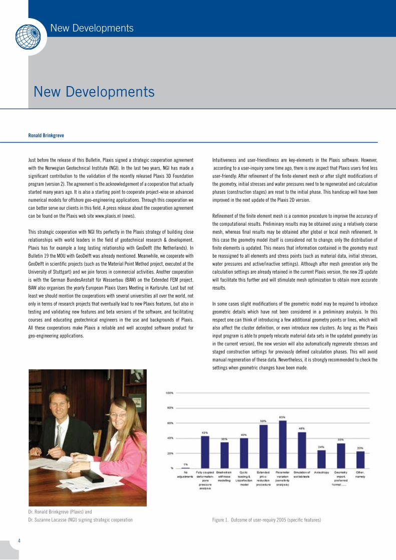
figure 1. outcome of user-requiry �005 (specific features)
dr. ronald Brinkgreve (Plaxis) and
dr. suzanne lacasse (nGi) signing strategic cooperation
5
New Developments
in addition to the Plaxis �d version, the new general Plaxis 3d model that is currently
being developed will have these facilities from the beginning of its existence. the internal
data structure has been designed such that properties are mainly assigned to the basic
volumes (like soil layers or excavation volumes) and are inherited by the resulting
sub-volumes as soon as basic volumes are crossed with other objects. Volume properties
are maintained when the geometry is modified. mesh generation, generation of element
properties from the (sub-)volumes, and initial stress generation is only considered after
definition of the calculation phases, just before the start of the finite element calculations.
this structure guarantees the consistency of model settings and facilitates the
optimization of the model from a simplified preliminary analysis to a more detailed final
run. more details about the new 3d model will be given in the next Plaxis bulletin.
Because of increasing activities, Plaxis is continuously searching for talented
professionals to join our team in delft. at the moment we have vacant positions
for a back-office manager and for a project manager with a geo-engineering back-
ground to further lead the successful Plaxis �d development line. for details and
applications see the announcement on the Plaxis website.
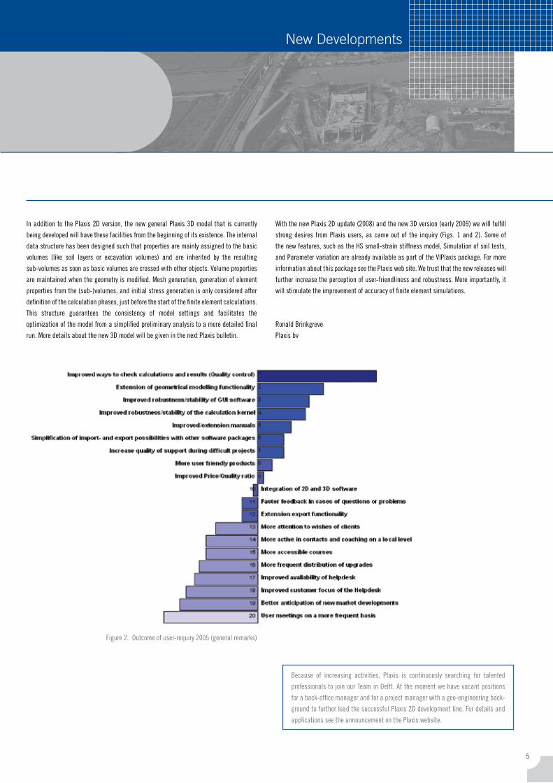
With the new Plaxis �d update (�008) and the new 3d version (early �009) we will fulfill
strong desires from Plaxis users, as came out of the inquiry (figs. 1 and �). some of
the new features, such as the Hs small-strain stiffness model, simulation of soil tests,
and Parameter variation are already available as part of the ViPlaxis package. for more
information about this package see the Plaxis web site. We trust that the new releases will
further increase the perception of user-friendliness and robustness. more importantly, it
will stimulate the improvement of accuracy of finite element simulations.
ronald Brinkgreve
Plaxis bv
figure �. outcome of user-requiry �005 (general remarks)
6
Stabilization of vertical cut using soil nailing
Plaxis Practice
G. l. sivakumar Babu, associate ProfessorDepartment of Civil Engineering, indian institute of science, Bangalore, Karnataka, indiaVikas Pratap singh, Research scholarDepartment of Civil Engineering, indian institute of science, Bangalore, Karnataka, india
Introductionsoil nailing has been used extensively as an in-situ reinforcement technique in many
parts of the world. the design and analysis are essentially based on limit equilibrium
methods (Gassler and Gudehus, 1981; Juran, 1985). one of the important aspects
of the analysis of in-situ earth reinforcement is in understanding the behaviour of
soil-nailed retaining walls. in a soil-nailed retaining wall, the properties and material
behaviour of three components—the native soil, the reinforcement (nails) and the facing
element—and their mutual interactions significantly affect the performance of
the structure. the behaviour of reinforced soil walls can be understood to some extent by
studying the state of stress within the reinforced zone (rowe and Ho, 1996). in addition,
various factors such as the construction sequence, the installation of nails, the connection
between the nails and the facing are likely to influence the behaviour. these influences
are not adequately addressed in the conventional design procedures based on limit
equilibrium methods, with which the wall in the present study was designed. Hence, for a better
understanding of the behaviour, it is necessary to assess the stability and performance of
soil-nailed walls using numerical simulations.
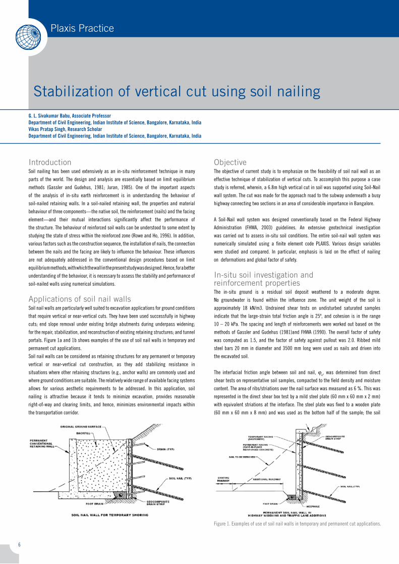
Applications of soil nail wallssoil nail walls are particularly well suited to excavation applications for ground conditions
that require vertical or near-vertical cuts. they have been used successfully in highway
cuts; end slope removal under existing bridge abutments during underpass widening;
for the repair, stabilization, and reconstruction of existing retaining structures; and tunnel
portals. figure 1a and 1b shows examples of the use of soil nail walls in temporary and
permanent cut applications.
soil nail walls can be considered as retaining structures for any permanent or temporary
vertical or near-vertical cut construction, as they add stabilizing resistance in
situations where other retaining structures (e.g., anchor walls) are commonly used and
where ground conditions are suitable. the relatively wide range of available facing systems
allows for various aesthetic requirements to be addressed. in this application, soil
nailing is attractive because it tends to minimize excavation, provides reasonable
right-of-way and clearing limits, and hence, minimizes environmental impacts within
the transportation corridor.
Objectivethe objective of current study is to emphasize on the feasibility of soil nail wall as an
effective technique of stabilization of vertical cuts. to accomplish this purpose a case
study is referred, wherein, a 6.8m high vertical cut in soil was supported using soil-nail
wall system. the cut was made for the approach road to the subway underneath a busy
highway connecting two sections in an area of considerable importance in Bangalore.
a soil-nail wall system was designed conventionally based on the federal Highway
administration (fHWa, �003) guidelines. an extensive geotechnical investigation
was carried out to assess in-situ soil conditions. the entire soil-nail wall system was
numerically simulated using a finite element code PlaXis. Various design variables
were studied and compared. in particular, emphasis is laid on the effect of nailing
on deformations and global factor of safety.
In-situ soil investigation and reinforcement propertiesthe in-situ ground is a residual soil deposit weathered to a moderate degree.
no groundwater is found within the influence zone. the unit weight of the soil is
approximately 18 kn/m3. Undrained shear tests on undisturbed saturated samples
indicate that the large-strain total friction angle is �5º, and cohesion is in the range
10 – �0 kPa. the spacing and length of reinforcements were worked out based on the
methods of Gassler and Gudehus (1981)and fHWa (1990). the overall factor of safety
was computed as 1.5, and the factor of safety against pullout was �.0. ribbed mild
steel bars �0 mm in diameter and 3500 mm long were used as nails and driven into
the excavated soil.
the interfacial friction angle between soil and nail, ju, was determined from direct
shear tests on representative soil samples, compacted to the field density and moisture
content. the area of ribs/striations over the nail surface was measured as 6 %. this was
represented in the direct shear box test by a mild steel plate (60 mm x 60 mm x � mm)
with equivalent striations at the interface. the steel plate was fixed to a wooden plate
(60 mm x 60 mm x 8 mm) and was used as the bottom half of the sample; the soil
figure 1. examples of use of soil nail walls in temporary and permanent cut applications.
7
Plaxis Practice
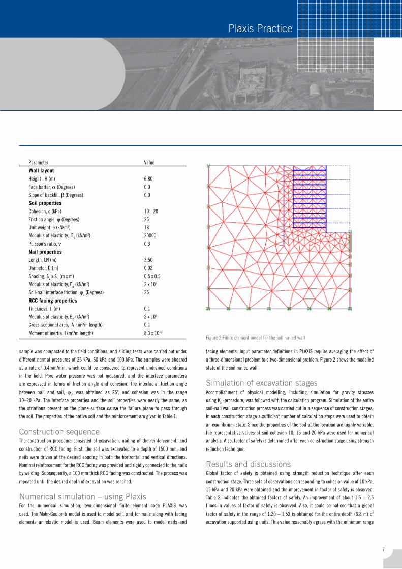
facing elements. input parameter definitions in PlaXis require averaging the effect of
a three-dimensional problem to a two-dimensional problem. figure � shows the modelled
state of the soil nailed wall.
Simulation of excavation stagesaccomplishment of physical modelling, including simulation for gravity stresses
using ko -procedure, was followed with the calculation program. simulation of the entire
soil-nail wall construction process was carried out in a sequence of construction stages.
in each construction stage a sufficient number of calculation steps were used to obtain
an equilibrium-state. since the properties of the soil at the location are highly variable,
the representative values of soil cohesion 10, 15 and �0 kPa were used for numerical
analysis. also, factor of safety is determined after each construction stage using strength
reduction technique.
Results and discussionsGlobal factor of safety is obtained using strength reduction technique after each
construction stage. three sets of observations corresponding to cohesion value of 10 kPa,
15 kPa and �0 kPa were obtained and the improvement in factor of safety is observed.
table � indicates the obtained factors of safety. an improvement of about 1.5 – �.5
times in values of factor of safety is observed. also, it could be noticed that a global
factor of safety in the range of 1.�0 – 1.53 is obtained for the entire depth (6.8 m) of
excavation supported using nails. this value reasonably agrees with the minimum range
sample was compacted to the field conditions, and sliding tests were carried out under
different normal pressures of �5 kPa, 50 kPa and 100 kPa. the samples were sheared
at a rate of 0.�mm/min, which could be considered to represent undrained conditions
in the field. Pore water pressure was not measured, and the interface parameters
are expressed in terms of friction angle and cohesion. the interfacial friction angle
between nail and soil, ju, was obtained as �5º, and cohesion was in the range
10–�0 kPa. the interface properties and the soil properties were nearly the same, as
the striations present on the plane surface cause the failure plane to pass through
the soil. the properties of the native soil and the reinforcement are given in table 1.
Construction sequencethe construction procedure consisted of excavation, nailing of the reinforcement, and
construction of rcc facing. first, the soil was excavated to a depth of 1500 mm, and
nails were driven at the desired spacing in both the horizontal and vertical directions.
nominal reinforcement for the rcc facing was provided and rigidly connected to the nails
by welding. subsequently, a 100 mm thick rcc facing was constructed. the process was
repeated until the desired depth of excavation was reached.
Numerical simulation – using Plaxisfor the numerical simulation, two-dimensional finite element code PlaXis was
used. the mohr-coulomb model is used to model soil, and for nails along with facing
elements an elastic model is used. Beam elements were used to model nails and
figure � finite element model for the soil nailed wall
Parameter Value
Wall layout
Height , H (m) 6.80
face batter, a (degrees) 0.0
slope of backfill, β (degrees) 0.0
Soil properties
cohesion, c (kPa) 10 - �0
friction angle, j (degrees) �5
Unit weight, γ (kn/m3) 18
modulus of elasticity, es (kn/m�) �0000
Poisson’s ratio, ν 0.3
Nail properties
length, ln (m) 3.50
diameter, d (m) 0.0�
spacing, sV x sH (m x m) 0.5 x 0.5
modulus of elasticity, en (kn/m�) � x 108
soil-nail interface friction, ju (degrees) �5
RCC facing properties
thickness, t (m) 0.1
modulus of elasticity, ec (kn/m�) � x 107
cross-sectional area, a (m�/m length) 0.1
moment of inertia, i (m�/m length) 8.3 x 10⁻⁵
8
Plaxis Practice
Stabilization of vertical cut using soil nailing
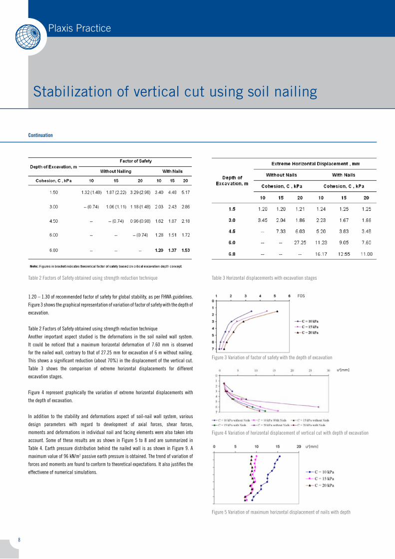
1.�0 – 1.30 of recommended factor of safety for global stability, as per fHWa guidelines.
figure 3 shows the graphical representation of variation of factor of safety with the depth of
excavation.
table � factors of safety obtained using strength reduction technique
another important aspect studied is the deformations in the soil nailed wall system.
it could be noticed that a maximum horizontal deformation of 7.60 mm is observed
for the nailed wall, contrary to that of �7.�5 mm for excavation of 6 m without nailing.
this shows a significant reduction (about 70%) in the displacement of the vertical cut.
table 3 shows the comparison of extreme horizontal displacements for different
excavation stages.
figure � represent graphically the variation of extreme horizontal displacements with
the depth of excavation.
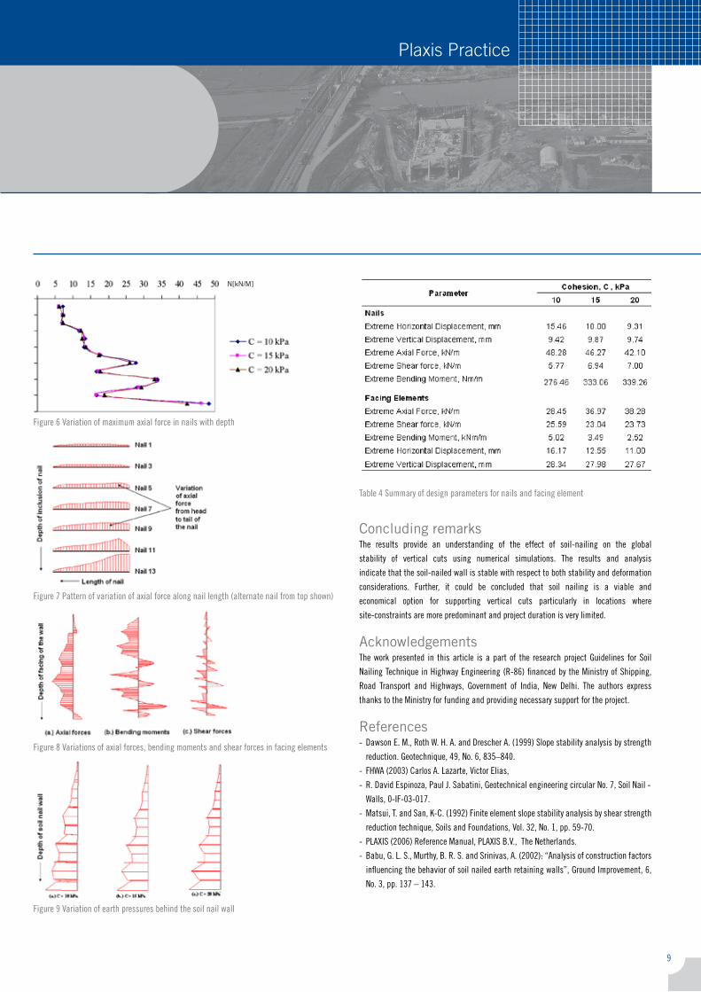
in addition to the stability and deformations aspect of soil-nail wall system, various
design parameters with regard to development of axial forces, shear forces,
moments and deformations in individual nail and facing elements were also taken into
account. some of these results are as shown in figure 5 to 8 and are summarized in
table �. earth pressure distribution behind the nailed wall is as shown in figure 9. a
maximum value of 96 kn/m� passive earth pressure is obtained. the trend of variation of
forces and moments are found to conform to theoretical expectations. it also justifies the
effectivene of numerical simulations.
table 3 Horizontal displacements with excavation stages
Continuation
table � factors of safety obtained using strength reduction technique
figure 3 Variation of factor of safety with the depth of excavation
figure � Variation of horizontal displacement of vertical cut with depth of excavation
figure 5 Variation of maximum horizontal displacement of nails with depth
FOS
ux[mm]
ux[mm]
9
Plaxis Practice
figure 6 Variation of maximum axial force in nails with depth
figure 7 Pattern of variation of axial force along nail length (alternate nail from top shown)
Concluding remarksthe results provide an understanding of the effect of soil-nailing on the global
stability of vertical cuts using numerical simulations. the results and analysis
indicate that the soil-nailed wall is stable with respect to both stability and deformation
considerations. further, it could be concluded that soil nailing is a viable and
economical option for supporting vertical cuts particularly in locations where
site-constraints are more predominant and project duration is very limited.
Acknowledgementsthe work presented in this article is a part of the research project Guidelines for soil
nailing technique in Highway engineering (r-86) financed by the ministry of shipping,
road transport and Highways, Government of india, new delhi. the authors express
thanks to the ministry for funding and providing necessary support for the project.
References- dawson e. m., roth W. H. a. and drescher a. (1999) slope stability analysis by strength
reduction. Geotechnique, �9, no. 6, 835–8�0.
- fHWa (�003) carlos a. lazarte, Victor elias,
- r. david espinoza, Paul J. sabatini, Geotechnical engineering circular no. 7, soil nail -
Walls, 0-if-03-017.
- matsui, t. and san, k-c. (199�) finite element slope stability analysis by shear strength
reduction technique, soils and foundations, Vol. 3�, no. 1, pp. 59-70.
- PlaXis (�006) reference manual, PlaXis B.V., the netherlands.
- Babu, G. l. s., murthy, B. r. s. and srinivas, a. (�00�): “analysis of construction factors
influencing the behavior of soil nailed earth retaining walls”, Ground improvement, 6,
no. 3, pp. 137 – 1�3.
table � summary of design parameters for nails and facing element
figure 9 Variation of earth pressures behind the soil nail wall
figure 8 Variations of axial forces, bending moments and shear forces in facing elements
N[kN/M]
10
Plaxis Practice Plaxis Practice
Designing a bridge with Plaxis 3D tunnel
P.G. van Duijnen, Movares The Netherlands
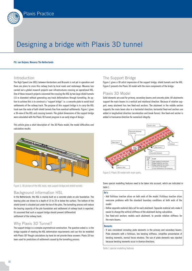
Introductionthe High speed line (Hsl) between amsterdam and Brussels is not yet in operation and
there are plans to cross this railway track by local roads and motorways. movares has
carried out a global research projects over infrastructures crossing an operational Hsl.
one of these research projects concerned the crossing the Hsl by two large shield tunnels
(15 m diameter) without generating any track deformations through tunnelling. an op-
tion to achieve this is to construct a “support bridge” i.e. a concerte plate to avoid local
settlements of the railway track. the purpose of this support bridge is to carry the Hsl
track over the route of both shield tunnels free from eventual settlements. figure 1 gives
a 3d-view of the Hsl and crossing tunnels. the global dimensions of the support bridge
were calculated with the Plaxis 3d tunnel program in an early stage of design.
this article gives a short description of the 3d Plaxis model, the model difficulties and
calculation results.
figure 1: 3d picture of the Hsl track, new support bridge and shield tunnels.
Background information HSLin the netherlands, the Hsl is mainly built on a concrete plate on pile foundation. the
bearing piles are driven to a depth of 15 to �0 m below the surface. the bottom of the
shield tunnel is situated just under the toe of the piles. the tunnelling process will reduce
the bearing capacity of the pile foundation and settlement of railway track is expected.
it’s assumed that such a support bridge should prevent (differential)
settlement of the railway track.
Why Plaxis 3D Tunnel?the support bridge is a complex asymmetrical construction. the question asked is: is the
bridge capable of meeting the Hsl deformation requirements and can this be modelled
with Plaxis 3d? rough calculations by hand do not provide these answers. Plaxis �d has
been used for predictions of settlement caused by the tunnelling process.
The Support Bridgefigure 1 gives a 3d artist impression of the support bridge, shield tunnels and the Hsl.
figure � presents the Plaxis 3d model with the main components of the bridge.
Plaxis 3D Modelsolid elements are used for primary, secondary beams and concrete plate. all abutments
support the main beams in a vertical and rotational direction. Because of rotation sup-
port, every abutment has two fixed-end anchors. the abutment in the middle section
supports the main beam also in a horizontal direction; horizontal fixed-end anchors are
added in longitudinal direction (acceleration and break forces). one fixed-end anchor is
added in transverse direction for numerical integrity.
figure �: Plaxis 3d model with main parts.
some special modelling features need to be taken into account, which are indicated in
table 1
Do’s- add fictitious inactive slices on both ends of the model. fictitious inactive slices
overcome problems with the standard boundary conditions at both ends of the
model.
- define separate material data set for each abutment. separate material sets make it
easier to change the vertical stiffness of the abutment during calculation.
- two fixed-end anchors models each abutment, to provide rotation stiffness for
the main beams.
Remarks
- it was considered including plate elements in the primary and secondary beams.
Plate elements with a fictitious, low bending stiffness, simplifies presentation of
bending moments, normal forces etcetera. the use of plate elements was rejected
because bending moments occur in diverse directions.
table 1 special modelling features
11
Plaxis Practice
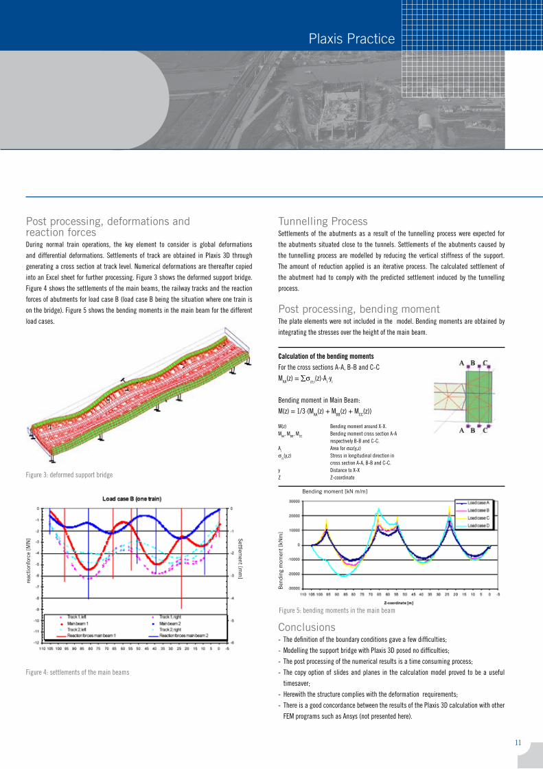
Post processing, deformations and reaction forcesduring normal train operations, the key element to consider is global deformations
and differential deformations. settlements of track are obtained in Plaxis 3d through
generating a cross section at track level. numerical deformations are thereafter copied
into an excel sheet for further processing. figure 3 shows the deformed support bridge.
figure � shows the settlements of the main beams, the railway tracks and the reaction
forces of abutments for load case B (load case B being the situation where one train is
on the bridge). figure 5 shows the bending moments in the main beam for the different
load cases.
figure 3: deformed support bridge
figure �: settlements of the main beams
Tunnelling Processsettlements of the abutments as a result of the tunnelling process were expected for
the abutments situated close to the tunnels. settlements of the abutments caused by
the tunnelling process are modelled by reducing the vertical stiffness of the support.
the amount of reduction applied is an iterative process. the calculated settlement of
the abutment had to comply with the predicted settlement induced by the tunnelling
process.
Post processing, bending momentthe plate elements were not included in the model. Bending moments are obtained by
integrating the stresses over the height of the main beam.
Conclusions- the definition of the boundary conditions gave a few difficulties;
- modelling the support bridge with Plaxis 3d posed no difficulties;
- the post processing of the numerical results is a time consuming process;
- the copy option of slides and planes in the calculation model proved to be a useful
timesaver;
- Herewith the structure complies with the deformation requirements;
- there is a good concordance between the results of the Plaxis 3d calculation with other
fem programs such as ansys (not presented here).
Calculation of the bending moments for the cross sections a-a, B-B and c-c
maa(z) = ∑σzz;i(z)⋅ai⋅yi
Bending moment in main Beam:
m(z) = 1/3⋅(maa(z) + mBB(z) + mcc(z))
m(z) Bending moment around X-X.maa, mBB, mcc Bending moment cross section a-a respectively B-B and c-c.ai area for σzz(y,z)σzz(y,z) stress in longitudinal direction in cross section a-a, B-B and c-c.y distance to X-XZ Z-coordinate
figure 5: bending moments in the main beam
reac
tion
forc
e [M
N] S
ettlement [m
m]
Ben
ding
mom
ent
[kN
m]
Bending moment [kN m/m]
1�
Plaxis Practice Plaxis Practice
sylvie Bretelle, Bruno Demay, agathe Touati, saiPEM-sa
Tangiers - Mediterranean harbor
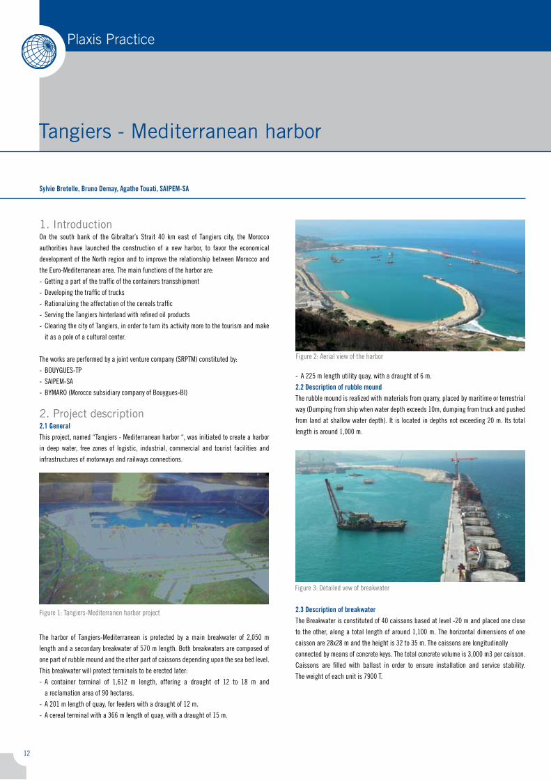
1. Introductionon the south bank of the Gibraltar’s strait �0 km east of tangiers city, the morocco
authorities have launched the construction of a new harbor, to favor the economical
development of the north region and to improve the relationship between morocco and
the euro-mediterranean area. the main functions of the harbor are:
- Getting a part of the traffic of the containers transshipment
- developing the traffic of trucks
- rationalizing the affectation of the cereals traffic
- serving the tangiers hinterland with refined oil products
- clearing the city of tangiers, in order to turn its activity more to the tourism and make
it as a pole of a cultural center.
the works are performed by a joint venture company (srPtm) constituted by:
- BoUyGUes-tP
- saiPem-sa
- Bymaro (morocco subsidiary company of Bouygues-Bi)
2. Project description2.1 Generalthis project, named “tangiers - mediterranean harbor “, was initiated to create a harbor
in deep water, free zones of logistic, industrial, commercial and tourist facilities and
infrastructures of motorways and railways connections.
the harbor of tangiers-mediterranean is protected by a main breakwater of �,050 m
length and a secondary breakwater of 570 m length. Both breakwaters are composed of
one part of rubble mound and the other part of caissons depending upon the sea bed level.
this breakwater will protect terminals to be erected later:
- a container terminal of 1,61� m length, offering a draught of 1� to 18 m and
a reclamation area of 90 hectares.
- a �01 m length of quay, for feeders with a draught of 1� m.
- a cereal terminal with a 366 m length of quay, with a draught of 15 m.
- a ��5 m length utility quay, with a draught of 6 m.
2.2 Description of rubble moundthe rubble mound is realized with materials from quarry, placed by maritime or terrestrial
way (dumping from ship when water depth exceeds 10m, dumping from truck and pushed
from land at shallow water depth). it is located in depths not exceeding �0 m. its total
length is around 1,000 m.
2.3 Description of breakwaterthe Breakwater is constituted of �0 caissons based at level -�0 m and placed one close
to the other, along a total length of around 1,100 m. the horizontal dimensions of one
caisson are �8x�8 m and the height is 3� to 35 m. the caissons are longitudinally
connected by means of concrete keys. the total concrete volume is 3,000 m3 per caisson.
caissons are filled with ballast in order to ensure installation and service stability.
the weight of each unit is 7900 t.
figure 1: tangiers-mediterranen harbor project
figure �: aerial view of the harbor
figure 3: detailed vew of breakwater
13
Plaxis Practice Plaxis Practice
Tangiers - Mediterranean harbor
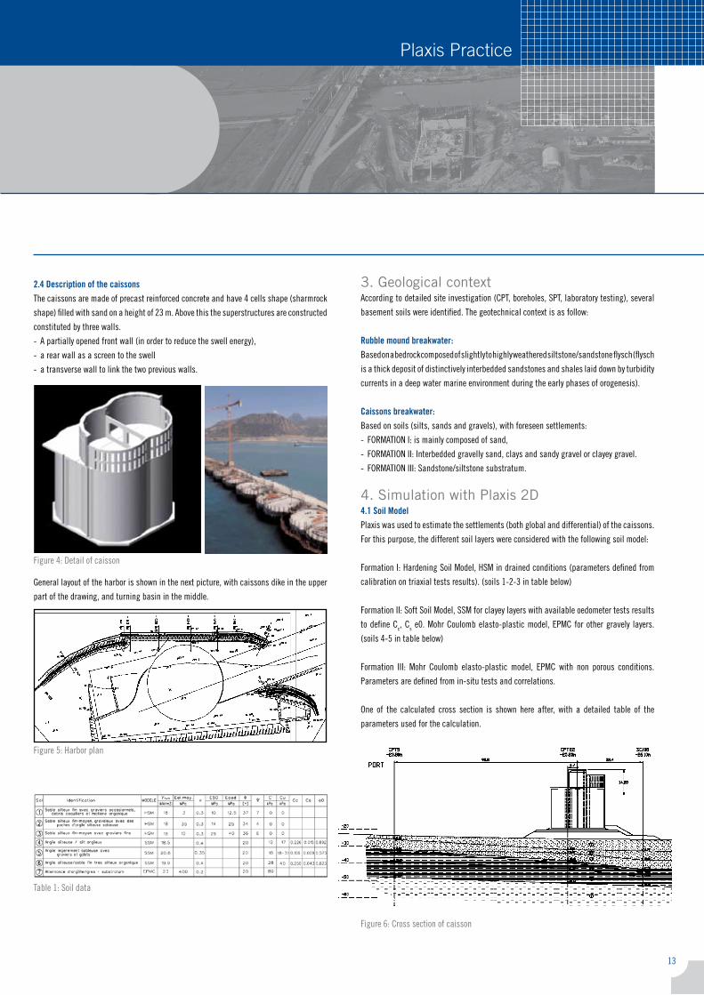
2.4 Description of the caissonsthe caissons are made of precast reinforced concrete and have � cells shape (sharmrock
shape) filled with sand on a height of �3 m. above this the superstructures are constructed
constituted by three walls.
- a partially opened front wall (in order to reduce the swell energy),
- a rear wall as a screen to the swell
- a transverse wall to link the two previous walls.
General layout of the harbor is shown in the next picture, with caissons dike in the upper
part of the drawing, and turning basin in the middle.
3. Geological contextaccording to detailed site investigation (cPt, boreholes, sPt, laboratory testing), several
basement soils were identified. the geotechnical context is as follow:
Rubble mound breakwater:Based on a bedrock composed of slightly to highly weathered siltstone/sandstone flysch (flysch
is a thick deposit of distinctively interbedded sandstones and shales laid down by turbidity
currents in a deep water marine environment during the early phases of orogenesis).
Caissons breakwater:Based on soils (silts, sands and gravels), with foreseen settlements:
- formation i: is mainly composed of sand,
- formation ii: interbedded gravelly sand, clays and sandy gravel or clayey gravel.
- formation iii: sandstone/siltstone substratum.
4. Simulation with Plaxis 2D4.1 soil ModelPlaxis was used to estimate the settlements (both global and differential) of the caissons.
for this purpose, the different soil layers were considered with the following soil model:
formation i: Hardening soil model, Hsm in drained conditions (parameters defined from
calibration on triaxial tests results). (soils 1-�-3 in table below)
formation ii: soft soil model, ssm for clayey layers with available oedometer tests results
to define cc, cs e0. mohr coulomb elasto-plastic model, ePmc for other gravely layers.
(soils �-5 in table below)
formation iii: mohr coulomb elasto-plastic model, ePmc with non porous conditions.
Parameters are defined from in-situ tests and correlations.
one of the calculated cross section is shown here after, with a detailed table of the
parameters used for the calculation.
figure �: detail of caisson
figure 5: Harbor plan
table 1: soil data
figure 6: cross section of caisson
1�
Plaxis Practice Plaxis Practice
Continuation
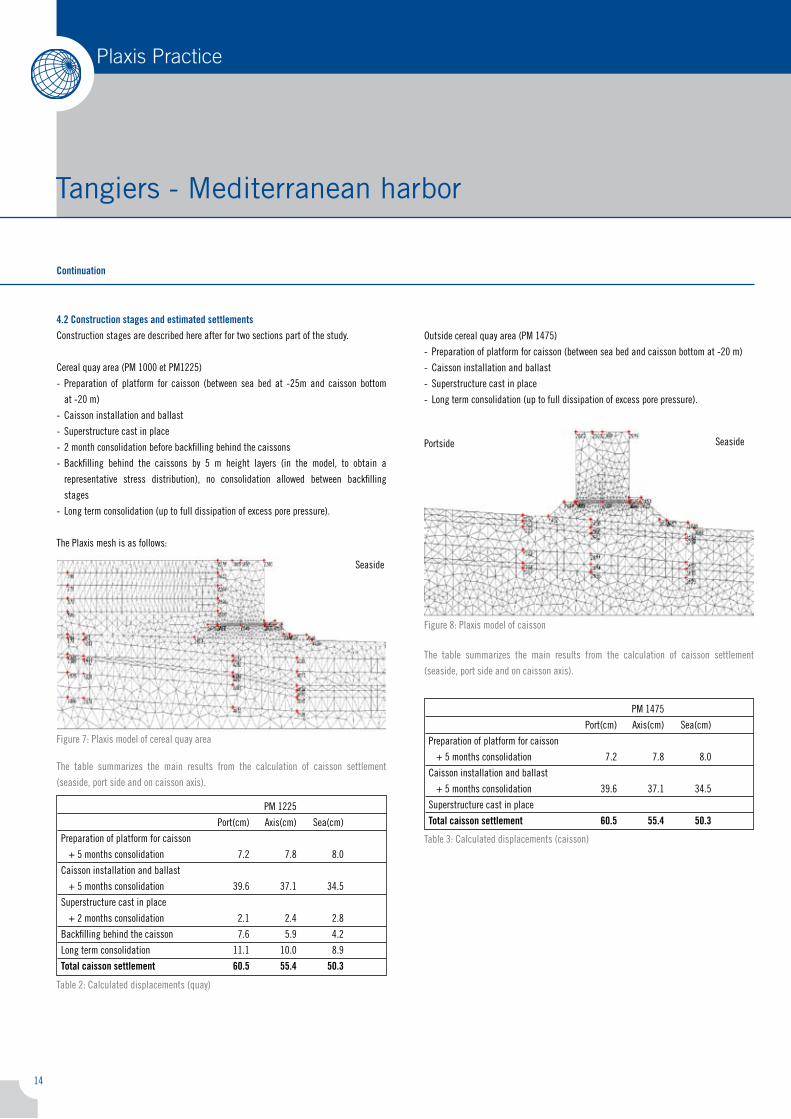
4.2 Construction stages and estimated settlementsconstruction stages are described here after for two sections part of the study.
cereal quay area (Pm 1000 et Pm1��5)
- Preparation of platform for caisson (between sea bed at -�5m and caisson bottom
at -�0 m)
- caisson installation and ballast
- superstructure cast in place
- � month consolidation before backfilling behind the caissons
- Backfilling behind the caissons by 5 m height layers (in the model, to obtain a
representative stress distribution), no consolidation allowed between backfilling
stages
- long term consolidation (up to full dissipation of excess pore pressure).
the Plaxis mesh is as follows:
the table summarizes the main results from the calculation of caisson settlement
(seaside, port side and on caisson axis).
outside cereal quay area (Pm 1�75)
- Preparation of platform for caisson (between sea bed and caisson bottom at -�0 m)
- caisson installation and ballast
- superstructure cast in place
- long term consolidation (up to full dissipation of excess pore pressure).
the Plaxis mesh is as follows:
the table summarizes the main results from the calculation of caisson settlement
(seaside, port side and on caisson axis).
Pm 1��5
Port(cm) axis(cm) sea(cm)
Preparation of platform for caisson
+ 5 months consolidation 7.� 7.8 8.0
caisson installation and ballast
+ 5 months consolidation 39.6 37.1 3�.5
superstructure cast in place
+ � months consolidation �.1 �.� �.8
Backfilling behind the caisson 7.6 5.9 �.�
long term consolidation 11.1 10.0 8.9
Total caisson settlement 60.5 55.4 50.3
Pm 1�75
Port(cm) axis(cm) sea(cm)
Preparation of platform for caisson
+ 5 months consolidation 7.� 7.8 8.0
caisson installation and ballast
+ 5 months consolidation 39.6 37.1 3�.5
superstructure cast in place
Total caisson settlement 60.5 55.4 50.3
Tangiers - Mediterranean harbor
seaside
seasidePortside
figure 7: Plaxis model of cereal quay area
table �: calculated displacements (quay)
table 3: calculated displacements (caisson)
figure 8: Plaxis model of caisson
15
Plaxis Practice Plaxis Practice
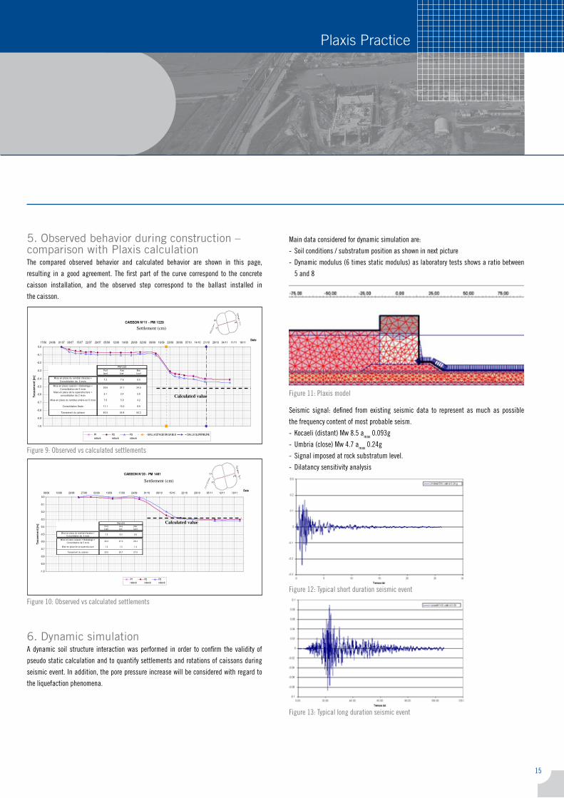
5. Observed behavior during construction – comparison with Plaxis calculationthe compared observed behavior and calculated behavior are shown in this page,
resulting in a good agreement. the first part of the curve correspond to the concrete
caisson installation, and the observed step correspond to the ballast installed in
the caisson.
6. Dynamic simulationa dynamic soil structure interaction was performed in order to confirm the validity of
pseudo static calculation and to quantify settlements and rotations of caissons during
seismic event. in addition, the pore pressure increase will be considered with regard to
the liquefaction phenomena.
main data considered for dynamic simulation are:
- soil conditions / substratum position as shown in next picture
- dynamic modulus (6 times static modulus) as laboratory tests shows a ratio between
5 and 8
seismic signal: defined from existing seismic data to represent as much as possible
the frequency content of most probable seism.
- kocaeli (distant) mw 8.5 amax 0.093g
- Umbria (close) mw �.7 amax 0.��g
- signal imposed at rock substratum level.
- dilatancy sensitivity analysis
Tangiers - Mediterranean harbor
installed in the caisson.
CAISSON N°11 - PM 1229
Tassements
-1.0
-0.9
-0.8
-0.7
-0.6
-0.5
-0.4
-0.3
-0.2
-0.1
0.0
17/06 24/06 01/07 08/07 15/07 22/07 29/07 05/08 12/08 19/08 26/08 02/09 09/09 16/09 23/09 30/09 07/10 14/10 21/10 28/10 04/11 11/11 18/11Date
Ta
ss
em
en
t [m
]
P1
relevé
P2
relevé
P3
relevé
BALLASTAGE EN SABLE DALLE SUPERIEURE
Calculated value
Settlement (cm)
CAISSON N°20 - PM 1481
Tassements
-1.0
-0.9
-0.8
-0.7
-0.6
-0.5
-0.4
-0.3
-0.2
-0.1
0.0
06/08 13/08 20/08 27/08 03/09 10/09 17/09 24/09 01/10 08/10 15/10 22/10 29/10 05/11 12/11 19/11Date
Ta
ss
em
en
t [m
]
P1
relevé
P2
relevé
P3
relevé
Calculated value
Settlement (cm)
figure 9: observed vs calculated settlements
figure 10: observed vs calculated settlements
figure 11: Plaxis model
figure 1�: typical short duration seismic event
figure 13: typical long duration seismic event
16
Plaxis PracticePlaxis Practice
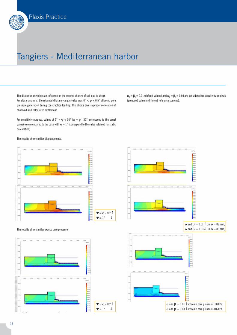
ar = βr = 0.01 (default values) and ar = βr = 0.03 are considered for sensitivity analysis
(proposed value in different reference sources).
the dilatancy angle has an influence on the volume change of soil due to shear.
for static analysis, the retained dilatancy angle value was 0° < ψ < 0.5° allowing pore
pressure generation during construction loading. this choice gives a proper correlation of
observed and calculated settlement.
for sensitivity purpose, values of 5° < ψ < 10° (ψ = j - 30°, correspond to the usual
value) were compared to the case with ψ = 1° (correspond to the value retained for static
calculation).
the results show similar displacements.
the results show similar excess pore pressure.
- rayleigh Parameters and sensitivity analysis
Tangiers - Mediterranean harbor
Ψ = j - 30° ↑Ψ = 1° ↓
Ψ = j - 30° ↑Ψ = 1° ↓
a and β = 0.01 ↑ dmax = 88 mm,
a and β = 0.03 ↓ dmax = 83 mm,
a and β = 0.01 ↑ extreme pore pressure 130 kPa
a and β = 0.03 ↓ extreme pore pressure 316 kPa
17
Plaxis PracticePlaxis Practice
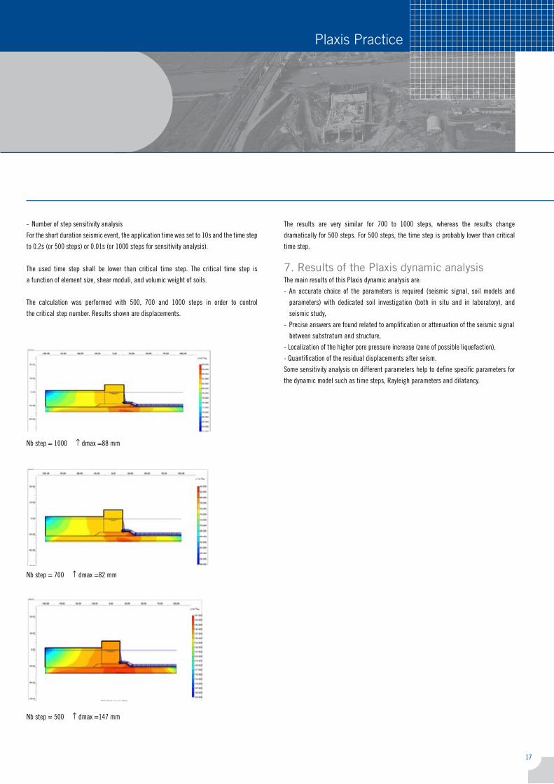
- number of step sensitivity analysis
for the short duration seismic event, the application time was set to 10s and the time step
to 0.�s (or 500 steps) or 0.01s (or 1000 steps for sensitivity analysis).
the used time step shall be lower than critical time step. the critical time step is
a function of element size, shear moduli, and volumic weight of soils.
the calculation was performed with 500, 700 and 1000 steps in order to control
the critical step number. results shown are displacements.
the results are very similar for 700 to 1000 steps, whereas the results change
dramatically for 500 steps. for 500 steps, the time step is probably lower than critical
time step.
7. Results of the Plaxis dynamic analysisthe main results of this Plaxis dynamic analysis are:
- an accurate choice of the parameters is required (seismic signal, soil models and
parameters) with dedicated soil investigation (both in situ and in laboratory), and
seismic study,
- Precise answers are found related to amplification or attenuation of the seismic signal
between substratum and structure,
- localization of the higher pore pressure increase (zone of possible liquefaction),
- Quantification of the residual displacements after seism.
some sensitivity analysis on different parameters help to define specific parameters for
the dynamic model such as time steps, rayleigh parameters and dilatancy.
Tangiers - Mediterranean harbor
nb step = 500 ↑ dmax =1�7 mm
nb step = 700 ↑ dmax =8� mm
nb step = 1000 ↑ dmax =88 mm
18
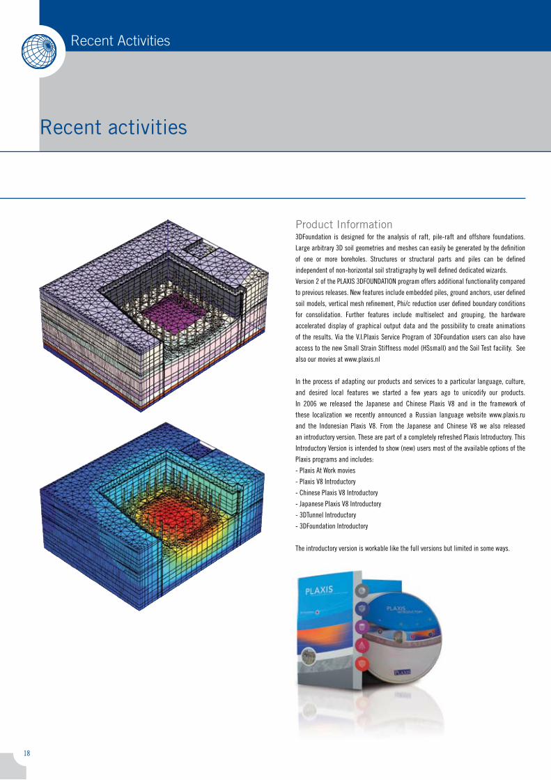
Product Information3dfoundation is designed for the analysis of raft, pile-raft and offshore foundations.
large arbitrary 3d soil geometries and meshes can easily be generated by the definition
of one or more boreholes. structures or structural parts and piles can be defined
independent of non-horizontal soil stratigraphy by well defined dedicated wizards.
Version � of the PlaXis 3dfoUndation program offers additional functionality compared
to previous releases. new features include embedded piles, ground anchors, user defined
soil models, vertical mesh refinement, Phi/c reduction user defined boundary conditions
for consolidation. further features include multiselect and grouping, the hardware
accelerated display of graphical output data and the possibility to create animations
of the results. Via the V.i.Plaxis service Program of 3dfoundation users can also have
access to the new small strain stiffness model (Hssmall) and the soil test facility. see
also our movies at www.plaxis.nl
in the process of adapting our products and services to a particular language, culture,
and desired local features we started a few years ago to unicodify our products.
in �006 we released the Japanese and chinese Plaxis V8 and in the framework of
these localization we recently announced a russian language website www.plaxis.ru
and the indonesian Plaxis V8. from the Japanese and chinese V8 we also released
an introductory version. these are part of a completely refreshed Plaxis introductory. this
introductory Version is intended to show (new) users most of the available options of the
Plaxis programs and includes:
- Plaxis at Work movies
- Plaxis V8 introductory
- chinese Plaxis V8 introductory
- Japanese Plaxis V8 introductory
- 3dtunnel introductory
- 3dfoundation introductory
the introductory version is workable like the full versions but limited in some ways.
Recent activities
Recent Activities
19
Recent Activities
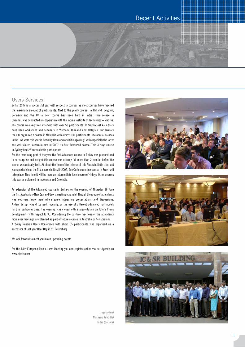
Users Servicesso far �007 is a successful year with respect to courses as most courses have reached
the maximum amount of participants. next to the yearly courses in Holland, Belgium,
Germany and the Uk a new course has been held in india. this course in
chennai was conducted in cooperation with the indian institute of technology – madras.
the course was very well attended with over 50 participants. in south-east asia there
have been workshops and seminars in Vietnam, thailand and malaysia. furthermore
the iem organized a course in malaysia with almost 100 participants. the annual courses
in the Usa were this year in Berkeley (January) and chicago (July) with especially the latter
one well visited. australia saw in �007 its first advanced course. this 3 days course
in sydney had �5 enthusiastic participants.
for the remaining part of the year the first advanced course in turkey was planned and
to our surprise and delight this course was already full more than � months before the
course was actually held. at about the time of the release of this Plaxis bulletin after a 5
years period since the first course in Brazil (�00�, sao carlos) another course in Brazil will
take place. this time it will be more an intermediate level course of � days. other courses
this year are planned in indonesia and colombia.
as extension of the advanced course in sydney, on the evening of thursday �6 June
the first australian-new Zealand Users meeting was held. though the group of attendants
was not very large there where some interesting presentations and discussions.
a dam design was discussed, focusing on the use of different advanced soil models
for this particular case. the evening was closed with a presentation on future Plaxis
developments with respect to 3d. considering the positive reactions of the attendants
more user meetings are planned as part of future courses in australia or new Zealand.
a �-day russian Users conference with about 85 participants was organized as a
successor of last year User day in st. Petersburg.
We look forward to meet you in our upcoming events.
for the 1�th european Plaxis Users meeting you can register online via our agenda on
www.plaxis.com
russia (top)
malaysia (middle)
india (bottom)
Plaxis finite element code for soil and rock analyses
Plaxis BVPo Box 57�
�600 an delft
the netherlands
tel: +31 (0)15 �51 77 �0
fax: +31 (0)15 �57 31 07
e-mail: [email protected]
Website: www.plaxis.nl
Activities 2007-2008
7006
301
1 – 4 October 2007Plaxis seminar and Workshops
thailand
1 – 4 October 2007course computational Geotechnics
rio de Janairo, Brazil
4 October 2007Geotechniekdag �007
Breda, the netherlands
16 October 2007oil and Gas seminar
aberdeen, United kingdom
17 - 18 October 2007Plaxis seminar and Workshop
taipei, taiwan
21 - 24 October 200710th anZ smGe,
Brisbane, australia
1 November 2007launch indonesian Plaxis V8
Jakarta, indonesia
1 – 4 November 200710th chinese Geotechnical conference
chongqin city, china
5 – 9 November 2007course computational Geotechnics
Bogotá, colombia
6 November 2007Plaxis Workshop
Jakarta, indonesia
7 - 9 November 20071�th european Plaxis User meeting
karlsruhe, Germany
14 – 16 November 20075th international symposium
on earth reinforcement
fukuoka, JaPan
21 –23 November 2007course computational Geotechnics
Paris, france
26 – 28 November 20071� african regional conference smGe,
yaounde, cameroon-africa
6 – 7 December 2007international symposium on
Geotechnical engineering
Bangkok, thailand
10 – 14 December 200713th asian regional conference on
soil mechanics and Geotechnical engineering
kolkata, india
January 2008course computational Geotechnics
Boston, U.s.a.
21 – 23 January 2008international course on computational
Geotechnics
schiphol, the netherlands
4 – 8 February 2008course computational Geotechnics
Brisbane, australia
12 – 13 February 2008Workshop “Plaxis: advanced soil models and
3d modelling”
Perth, australia
10 – 13 March 2008international course on computational
Geotechnics
antwerp, Belgium
9 – 12 March 2008Geo congres 08
new orleans, Usa
Related Documents