1 Plasma-thermal purification and annealing of carbon nanotubes Asmus Meyer-Plath * , Guillermo Orts-Gil, Sergey Petrov, Franz Oleszak, Heinz-Eberhard Maneck, Ilona Dörfel, Oskar Haase, Silke Richter, Reinhard Mach BAM – Federal Institute for Materials Research and Testing, Division 6.5, Unter den Eichen 87, 12205 Berlin, Germany. Abstract We have developed a very fast and entirely gas-phase based purification technique for carbon nanotubes (CNT) that allows removing metal and metal oxide impurities with high effectiveness. CNT agglomerates from chemical vapor deposition (CVD) synthesis which contained carbon encapsulated catalysts were injected into an atmospheric plasma torch. Very high heating rates allow for quasi-instantaneous vaporization of catalyst particles. This way, metal vapors are hyposized to break mechanically instable encapsulations and effuse from incomplete ones faster than thermally induced graphitization stabilizes such particle encapsulations. The ash content of multi-walled (MW) CNT samples was reduced to less than 15 % of the initial value within a few milliseconds. Also the metal content of single-walled (SW) CNT agglomerates was significantly reduced. Repeated injection of CNT agglomerates into the plasma torch resulted in higher-purity products of improved structural integrity and increased oxidation resistance. * Corresponding author. Fax +49 30 8104 1637. E-mail address: [email protected] (A. Meyer-Plath)

Welcome message from author
This document is posted to help you gain knowledge. Please leave a comment to let me know what you think about it! Share it to your friends and learn new things together.
Transcript
1
Plasma-thermal purification and annealing of
carbon nanotubes
Asmus Meyer-Plath*, Guillermo Orts-Gil, Sergey Petrov, Franz Oleszak, Heinz-Eberhard
Maneck, Ilona Dörfel, Oskar Haase, Silke Richter, Reinhard Mach
BAM – Federal Institute for Materials Research and Testing, Division 6.5, Unter den Eichen
87, 12205 Berlin, Germany.
Abstract
We have developed a very fast and entirely gas-phase based purification technique for carbon
nanotubes (CNT) that allows removing metal and metal oxide impurities with high
effectiveness. CNT agglomerates from chemical vapor deposition (CVD) synthesis which
contained carbon encapsulated catalysts were injected into an atmospheric plasma torch. Very
high heating rates allow for quasi-instantaneous vaporization of catalyst particles. This way,
metal vapors are hyposized to break mechanically instable encapsulations and effuse from
incomplete ones faster than thermally induced graphitization stabilizes such particle
encapsulations. The ash content of multi-walled (MW) CNT samples was reduced to less than
15 % of the initial value within a few milliseconds. Also the metal content of single-walled
(SW) CNT agglomerates was significantly reduced. Repeated injection of CNT agglomerates
into the plasma torch resulted in higher-purity products of improved structural integrity and
increased oxidation resistance.
* Corresponding author. Fax +49 30 8104 1637. E-mail address: [email protected] (A. Meyer-Plath)
ameyerpl
Textfeld
http://www.sciencedirect.com/science/article/pii/S0008622312003648
ameyerpl
Textfeld
10.1016/j.carbon.2012.04.049
2
1. Introduction
During the last two decades, significant progress has been made on the synthesis of CNTs
with respect to growth efficiency and structural order. Impurities resulting from the CNT
synthesis are nonetheless still an important subject of contemporary research. They generally
deteriorate desired properties of CNTs and of derived products like composites. Much
research has been devoted to the removal of amorphous carbon, nanographites or fullerene-
like impurities by selective oxidation in liquid and gas phase [1]. Also plasma-based
approaches have been studied [2,3].
Although metal-free synthesis of CNTs is possible [4], metal catalysts increase the
conversion efficiency of hydrocarbons to nanotubular carbons and can give control over the
tube structure [5]. They are therefore key ingredients for the ongoing upscaling of CNT
production by fixed- and fluidized-bed CVD. During synthesis, catalysts react with carbon
precursors to tubular structures and encapsulating carbon overcoats. Together with metal
oxide supports they may attach to or become incorporated into the CNT product [6]. This is
problematic for many applications. Catalyst metals like nickel, cobalt or yttrium, are of
toxicological concern [7]. While un-encapsulated catalyst metals may be readily bio-available,
encapsulated ones may show metal ion leaching only on the long-term after (bio-)degradation
of their carbon shell. The removal of such encapsulated catalysts is a challenge and motivated
the development of the process presented here.
The lowest amount of metal impurities is currently obtainable by super-growth of vertically-
aligned CNTs on catalyst-coated substrates [8]. Contemporary mass production of multi-
walled CNTs by fluidized bed CVD synthesis generally results in 1-10 wt.% impurities [6].
Whereas the synthesis of single-walled CNTs by the arc or HiPCO method typically results in
a metal content of 20-30 wt.% [9]. In accord with the economic and scientific value of purified
CNTs, especially of SWCNTs, many different approaches have been developed to remove
3
metals and metal oxides [10–15].
The still most widely applied metal purification method is mineral acid washing, by which
incompletely encapsulated metal impurities can be readily converted to water soluble metal
halides. For carbon encapsulated impurities however, preceding oxidative treatment in
oxidizing acids or oxygen containing gas phases is necessary in order to perforate carbon
shells and render enclosed metals accessible to subsequent mineral acids dissolution [1,16].
Such oxidative treatment requires careful optimization, since it may cause CNT structure
defects and unintended chemical functionalization. In addition, byproducts like oxidized CNT
wall fragments can be formed. Such CNT-derived surfactants may be difficult to remove [17].
Since the worldwide production capacities for CNTs through CVD synthesis have
meanwhile surpassed the metric kiloton scale, acid purification concepts that were developed
on the lab scale have to prove their purification and cost-effectiveness for mass processing.
Especially acid purification and subsequent neutral washing steps for CNT agglomerates of
low apparent density, which are typical for industry-scale fluidized-bed mass production,
require handling large volumes of acids and waste waters as well as time-consuming filtering
and drying steps. Therefore entirely gas-phase-based metal purification concepts like the one
presented here, may be advantageous since they allow avoiding dry-wet-dry transfer steps.
The high thermal stability of CNTs under inert conditions allows thermal annealing in
graphite furnaces, sometimes supported by vacuum or halogen purification gases. It is well
known to be effective in metal removal, structure annealing and reduction of functional groups
[18]. The removal of nanosized CNT catalyst particles may be facilitated by melting point
depression [19]. Sufficiently high temperatures and long processing times from a few minutes
up to several hours may even remove incompletely encapsulated metals by diffusion processes
but are generally accompanied by – not always desired – graphitization of the CNTs and
carbonaceous impurities like catalyst coatings [20,21].
4
Here, a new approach to CNT purification by thermal annealing is presented that uses
thermal plasma processing. In contrast to furnace purification, the new approach uses
extremely high heating rates and allows processing times in the millisecond range.
2. Materials and methods
2.1 Materials
The performance of the new technique was studied for MWCNT and SWCNT agglomerates
from commercial fluidized-bed CVD synthesis with an ash content in the order of 2 wt. %.
MWCNT agglomerates of type “Baytubes® C150P” were purchased from Bayer
MaterialScience AG, Germany. The results of plasma-thermal purification were benchmarked
against a commercially metal-depleted MWCNT material of type “Baytubes® C150HP” from
the same company. The MWCNT agglomerates of 50-800 µm size exhibited a median
diameter of 250 µm and apparent density of about 160 kg/m³. The MWCNT were specified to
have a mean diameter of 13 nm and a BET surface of 250 m²/g. SWCNT agglomerates of type
“Elicarb® PR925” of comparable agglomerate size were purchased from Thomas Swan & Co.
Ltd., United Kingdom. The SWCNT were specified to have a mean diameter of 0.9-1.7 nm
and a BET surface of 700 m²/g.
2.2 Plasma processing
MWCNT and SWCNT agglomerates were dispersed at a controlled feeding rate of 100 g/h
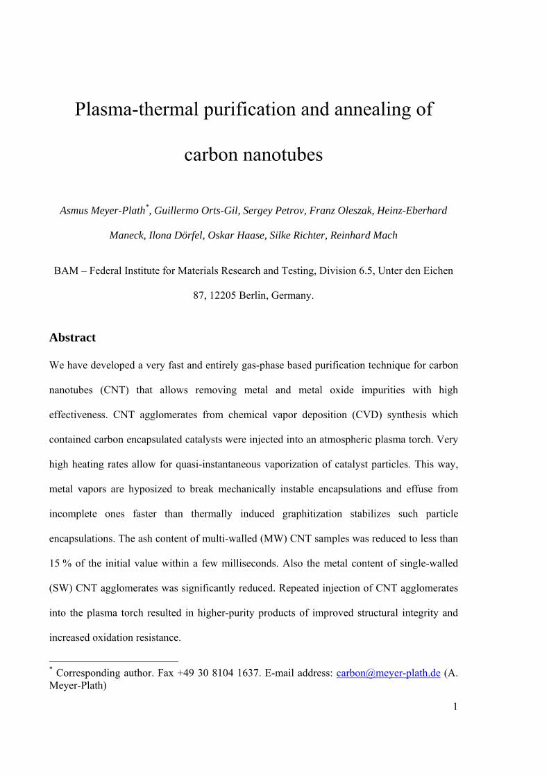
into a process gas stream. The formed aerosol was injected into a thermal plasma torch
through a hollow probe, cf. Figure 1. The plasma torch was generated inductively by a 3-
winding coil around a 50 mm quartz tube which was supplied with 4 MHz radio frequency
power. Standard plasma torch operation parameters were 12 kW power at a gas flow of 78 slm
argon and 2.5 slm hydrogen. The equivalent thermodynamic energy of the plasma torch core
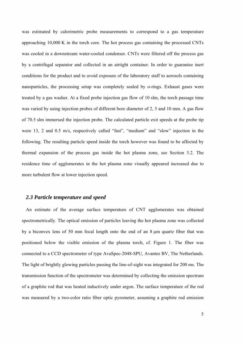
5
was estimated by calorimetric probe measurements to correspond to a gas temperature
approaching 10,000 K in the torch core. The hot process gas containing the processed CNTs
was cooled in a downstream water-cooled condenser. CNTs were filtered off the process gas
by a centrifugal separator and collected in an airtight container. In order to guarantee inert
conditions for the product and to avoid exposure of the laboratory staff to aerosols containing
nanoparticles, the processing setup was completely sealed by o-rings. Exhaust gases were
treated by a gas washer. At a fixed probe injection gas flow of 10 slm, the torch passage time
was varied by using injection probes of different bore diameter of 2, 5 and 10 mm. A gas flow
of 70.5 slm immersed the injection probe. The calculated particle exit speeds at the probe tip
were 13, 2 and 0.5 m/s, respectively called “fast”, “medium” and “slow” injection in the
following. The resulting particle speed inside the torch however was found to be affected by
thermal expansion of the process gas inside the hot plasma zone, see Section 3.2. The
residence time of agglomerates in the hot plasma zone visually appeared increased due to
more turbulent flow at lower injection speed.
2.3 Particle temperature and speed
An estimate of the average surface temperature of CNT agglomerates was obtained
spectrometrically. The optical emission of particles leaving the hot plasma zone was collected
by a biconvex lens of 50 mm focal length onto the end of an 8 µm quartz fiber that was
positioned below the visible emission of the plasma torch, cf. Figure 1. The fiber was
connected to a CCD spectrometer of type AvaSpec-2048-SPU, Avantes BV, The Netherlands.
The light of brightly glowing particles passing the line-of-sight was integrated for 200 ms. The
transmission function of the spectrometer was determined by collecting the emission spectrum
of a graphite rod that was heated inductively under argon. The surface temperature of the rod
was measured by a two-color ratio fiber optic pyrometer, assuming a graphite rod emission
6
coefficient of 90 %. The theoretical black body spectrum was fitted to the continuum radiation
part of the emission spectrum of the CNT agglomerates in the spectral range from 300-
950 nm.
Measurement of the lengths of trajectories of glowing particle on digital photographs taken
with an exposure time of 1/2000 s provided information of individual particle speeds.
2.4 Chemical and structural characterization
The residual mass was determined after ashing CNT samples in a furnace in air at 800 °C
for 4 h. Quantitative metal analysis of MWCNTs and SWCNTs was performed by electro-
thermal vaporization inductively coupled plasma optical emission spectroscopy (ETV-ICP
OES) and direct current (DC) arc OES analysis, respectively, using a TJA IRIS Advantage
DUO HR ICP OES spectrometer by Fischer Scientific GmbH, Germany. For ETV-ICP OES it
was coupled with an ETV 4000 by Spectral Systems, Germany. For DC arc OES, a Spectral
Systems DCA-301 direct current arc was used instead of the ICP burner [22]. The thermal
stability of the samples was determined by thermogravimetric analysis (TGA) in synthetic air
at a heating rate of 1 or 10 K/min. Raman spectra were acquired at 514.532 nm with a laser
power of 2 mW and laser spot size of 2 µm diameter on a LabRAM HR spectrometer by
Horiba Jobin Yvon GmbH, Germany. The measurements were taken at four different sample
spots. TEM investigations were performed on a JEOL JEM 2200-FS transmission electron
microscope operating at 200 kV equipped with an in-column omega-type energy filter. TEM
samples were prepared by immersion of Cu TEM grids coated with a holey amorphous carbon
film (S-147-3 Plano, Germany) into ethanolic suspensions of CNTs and solvent evaporation in
a dust-protected atmosphere.

7
3. Results and Discussion
3.1 CNT structure retention and oxidative stability
The extreme torch enthalpy of our device is in principle capable of evaporating metallic
impurities and destroying the CNT structure by graphite sublimation. CNT agglomerates were
found to leave the torch in a whitish glowing state. The spectroscopic observation of C2 Swan
band emissions below the plasma torch indicate that CNT agglomerates are treated close to the
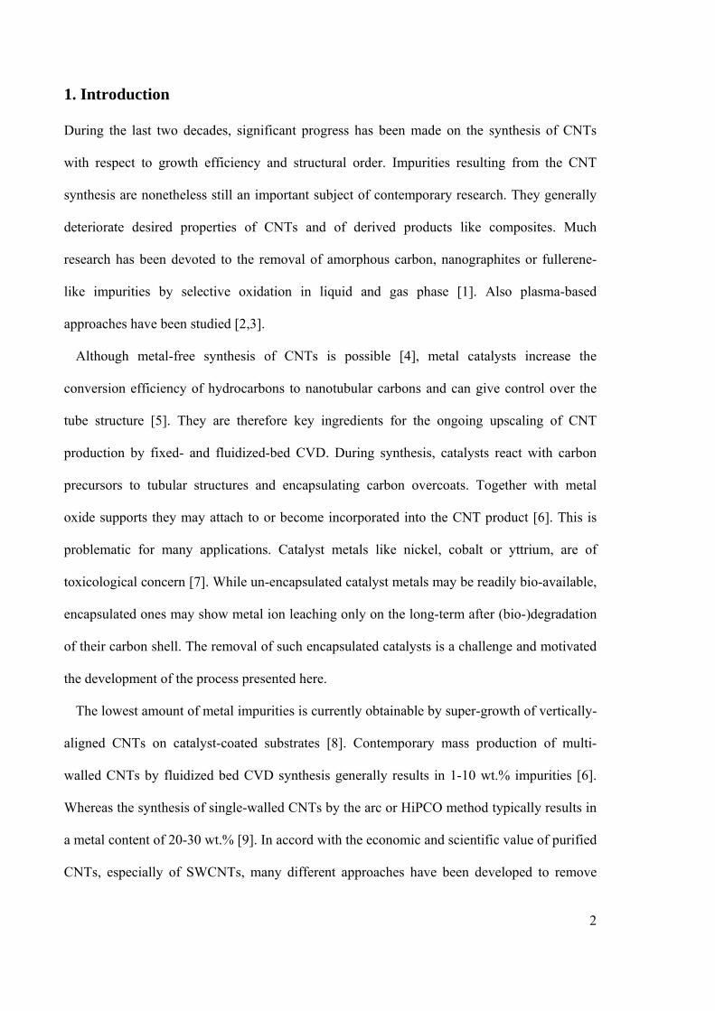
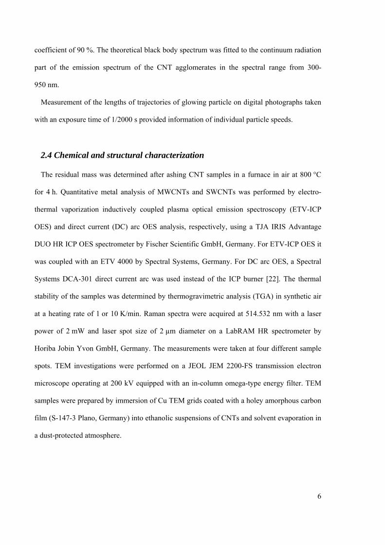
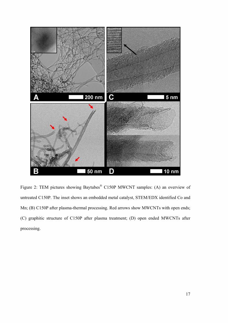
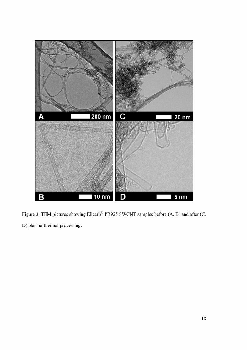
carbon sublimation temperature. However, the TEM images in Figures 2 and 3 show that the
integrity of the tubular CNT structural can be preserved at sufficiently short torch passage
time. Depending on process conditions and number of processing cycles, significant structure
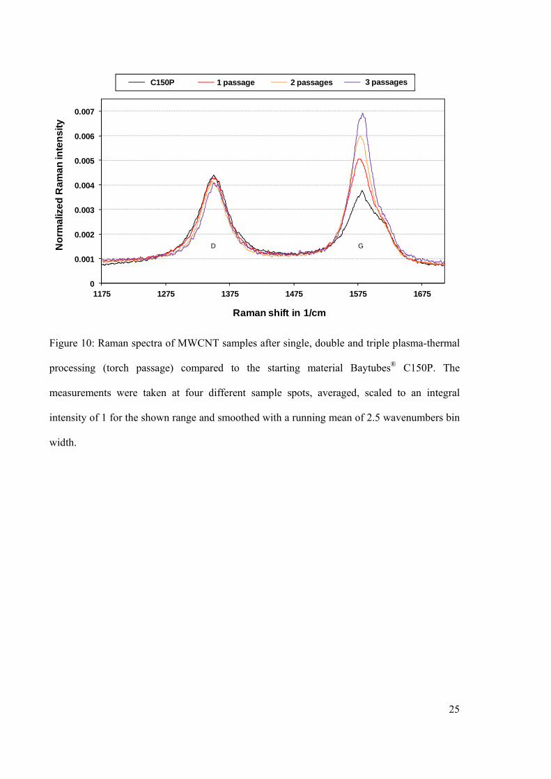
improvements are observable for MWCNTs using Raman spectroscopy in Figure 10. They
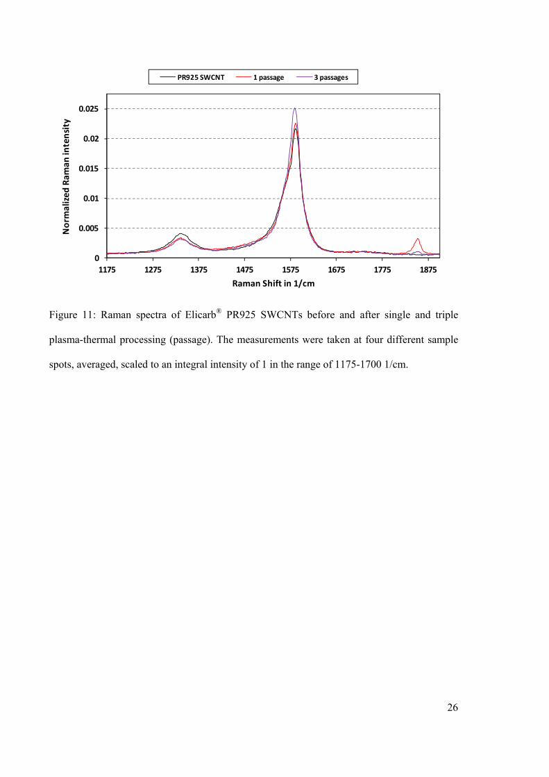
indicate an increase of the G band relative to the D band. Also the processed SWCNT samples
show small structural improvements according to the Raman spectra in Figure 11. The spectra
of processed SWCNT exhibit an additional peak at about 1850 cm-1. It has been attributed to
chain-like carbon material inside multi- or double-walled CNTs and is a characteristic of heat-
treated CNTs [23–25]. Jinno et al. reported disappearance of the peak after enhanced high
temperature annealing [23]. Here, the peak disappeared after repeated high temperature
annealing. According to Fantini et al., the resonance peak at 1850 cm-1 can result from the
coalescence of the inner tubes of neighboring double-walled CNT by linear carbon chains,
forming at special annealing temperatures [24]. This indicates the necessity of further work on
thermally induced diameter and (chiral) structure changes of CNTs. Also the differential TGA
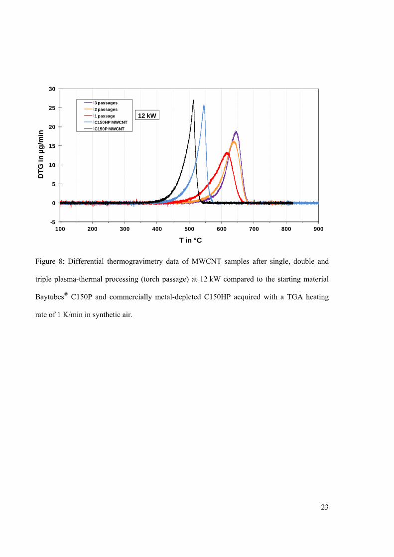
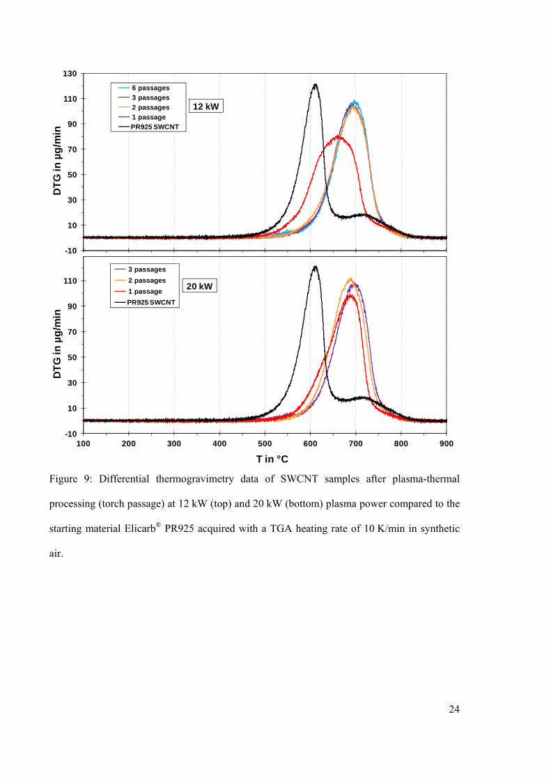
curves in Figures 8 and 9 show strong improvements in oxidative stability of up to 125 K for
the MWCNT and 90 K for the SWCNT samples.
3.2 Purification effect
Optical emission spectra of CNT agglomerates were acquired for the three different
8
injection speeds. By adapting the black body temperature, a Planck emission spectrum was
fitted to the continuum radiation part of measured emission spectra. The reliability of this
approach is however restricted since the expected emission maximum at about 1050 nm was
not determined directly and spectral regions with C2-Swan band emissions from carbon
sublimation had to be omitted. This way CNT agglomerate temperatures were determined to
be approximately 2400, 2500 and 2700 °C for injection probes of 2, 5 and 10 mm inner bore,
corresponding to fast, medium and slow injection.
The average particle speeds inside the torch, as determined from track length on
photographs of glowing particles, were (21 ± 6), (13 ± 2) and (10 ± 1) m/s for injection probes
of 2, 5 and 10 mm inner bore. As discussed in Section 2.2, the speeds are deviating from the
calculated speeds of 13, 2 and 0.5 m/s at the tip of the injection probe. The transit times for the
hot plasma zone of about 150 mm length therefore lie in the order of 7, 12 and 15 ms,
respectively. Together with the average particle temperature estimates, particle heating rates
are expected to exceed 150,000 K/s. Such high heating rates could quasi instantaneously
vaporize volatile impurities and allow purifying metal-containing CNTs.
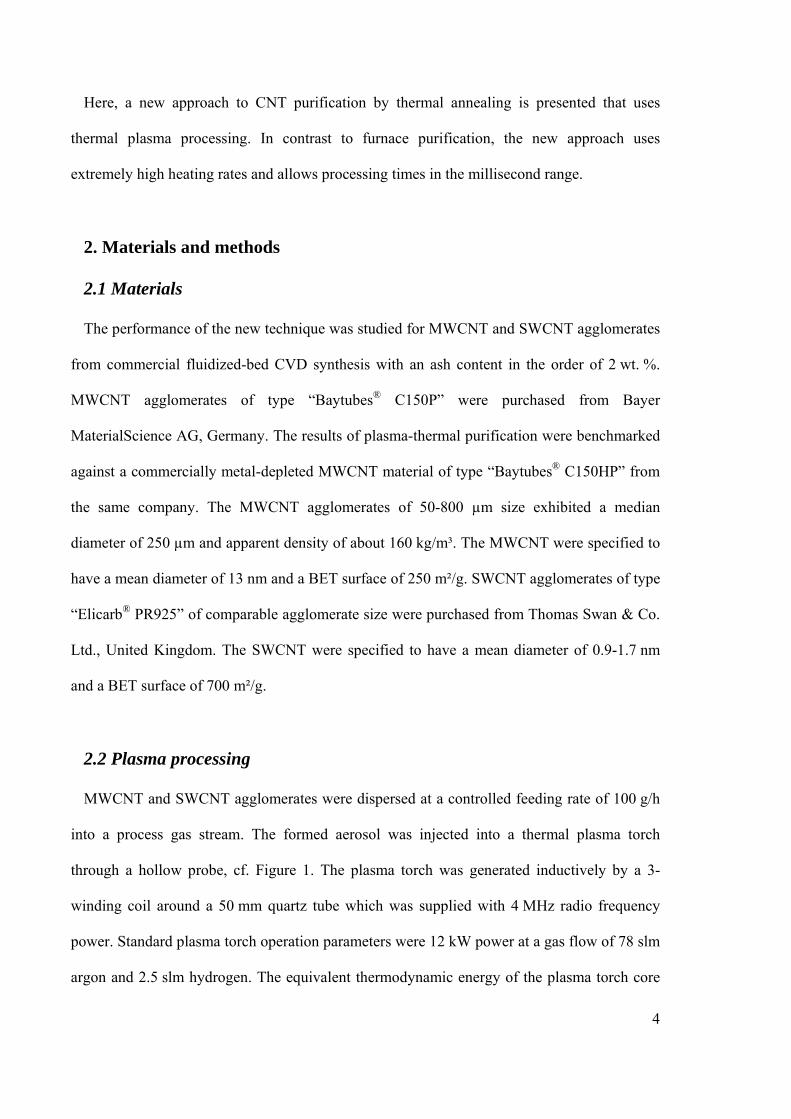
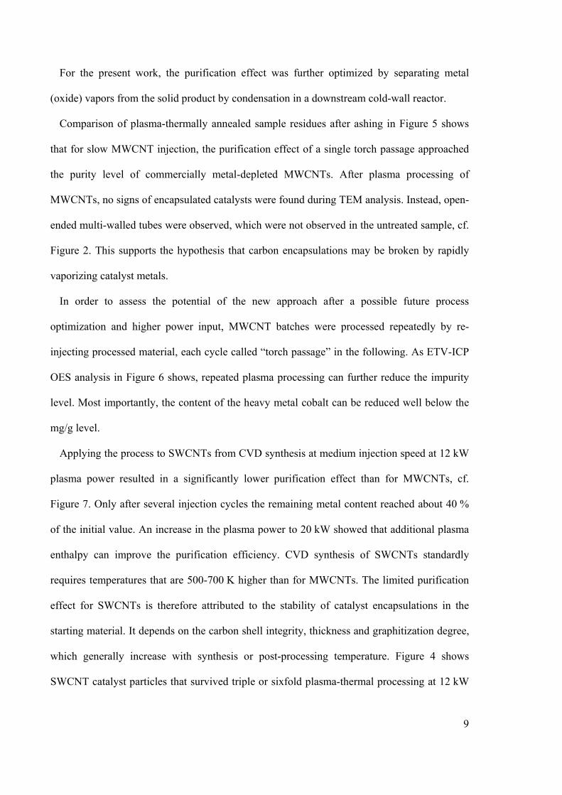
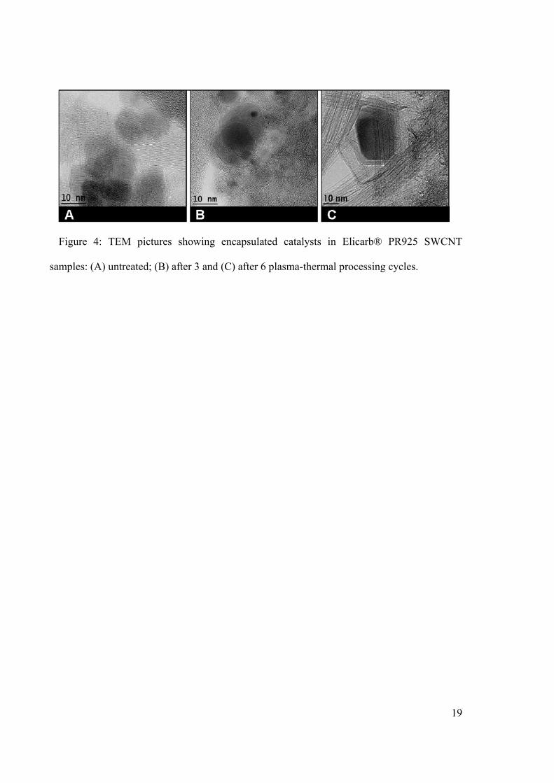
High-temperature annealing promotes both vaporization of metals as well as graphitization
of catalyst encapsulations. Figure 4 shows how quick the graphitization of carbon shells in a
SWCNT sample can proceed. Only 3 to 6 hot plasma zone passages of a few milliseconds
each were sufficient to form highly graphitic encapsulations. Therefore, if the temperature
during furnace annealing rises too slowly, any graphitization progress of encapsulations before
metal vaporization temperatures are reached will reduce the purification effectiveness.
A rapid vapor pressure build-up inside a closed encapsulation may break mechanically weak
carbon shells faster than a thermally induced reordering and graphitization may improve the
encapsulation’s integrity and stability. This way, optimized plasma-thermal annealing can
open a process window for the efficient removal of carbon-encapsulated catalysts.
9
For the present work, the purification effect was further optimized by separating metal
(oxide) vapors from the solid product by condensation in a downstream cold-wall reactor.
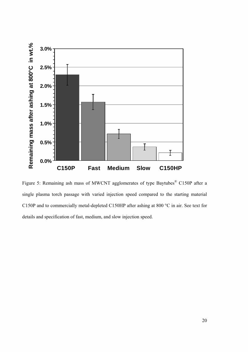
Comparison of plasma-thermally annealed sample residues after ashing in Figure 5 shows
that for slow MWCNT injection, the purification effect of a single torch passage approached
the purity level of commercially metal-depleted MWCNTs. After plasma processing of
MWCNTs, no signs of encapsulated catalysts were found during TEM analysis. Instead, open-
ended multi-walled tubes were observed, which were not observed in the untreated sample, cf.
Figure 2. This supports the hypothesis that carbon encapsulations may be broken by rapidly
vaporizing catalyst metals.
In order to assess the potential of the new approach after a possible future process
optimization and higher power input, MWCNT batches were processed repeatedly by re-
injecting processed material, each cycle called “torch passage” in the following. As ETV-ICP
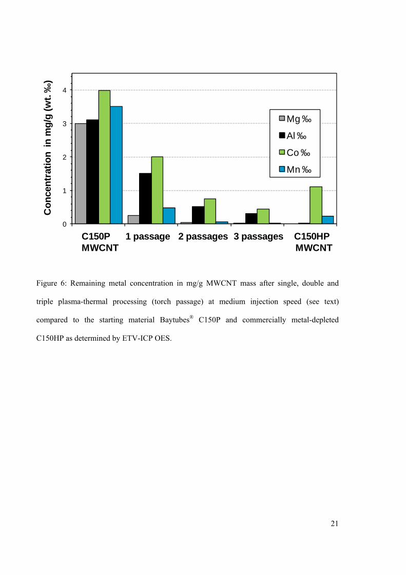
OES analysis in Figure 6 shows, repeated plasma processing can further reduce the impurity
level. Most importantly, the content of the heavy metal cobalt can be reduced well below the
mg/g level.
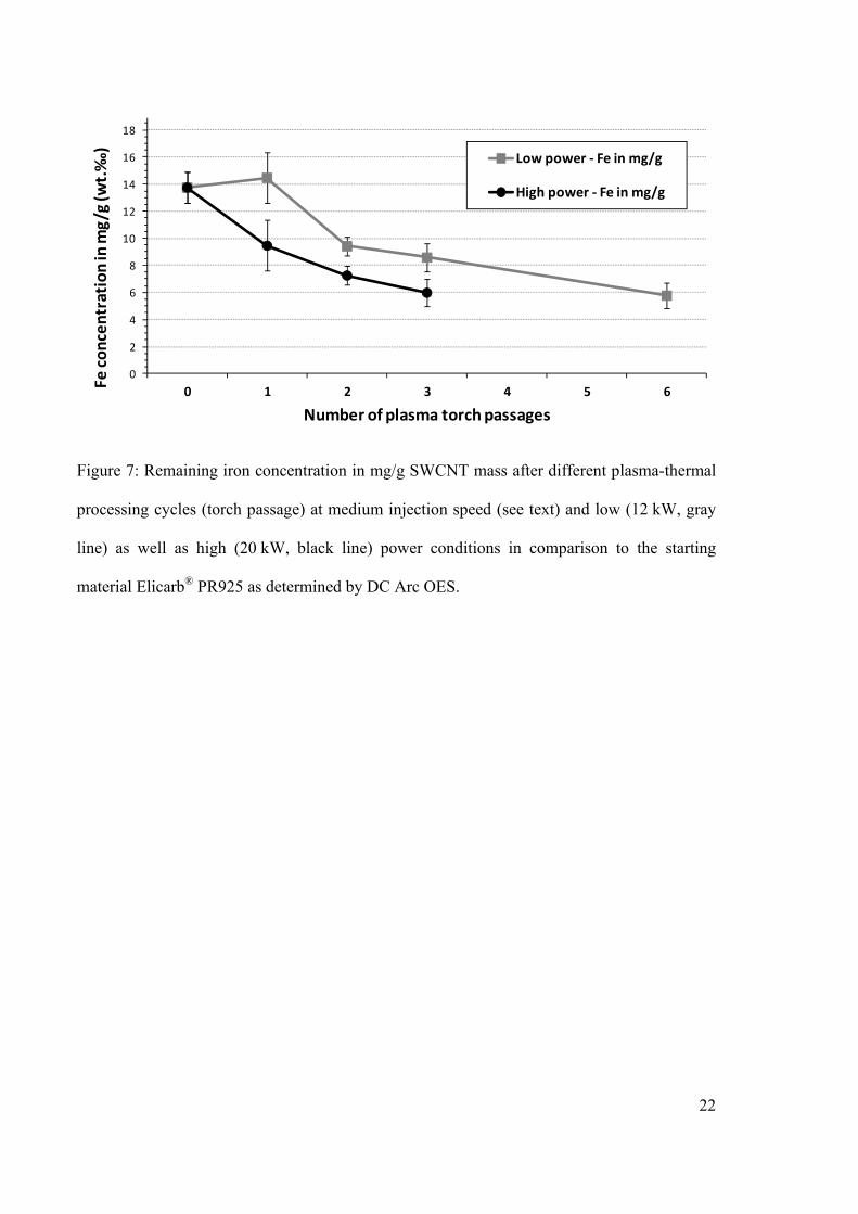
Applying the process to SWCNTs from CVD synthesis at medium injection speed at 12 kW
plasma power resulted in a significantly lower purification effect than for MWCNTs, cf.
Figure 7. Only after several injection cycles the remaining metal content reached about 40 %
of the initial value. An increase in the plasma power to 20 kW showed that additional plasma
enthalpy can improve the purification efficiency. CVD synthesis of SWCNTs standardly
requires temperatures that are 500-700 K higher than for MWCNTs. The limited purification
effect for SWCNTs is therefore attributed to the stability of catalyst encapsulations in the
starting material. It depends on the carbon shell integrity, thickness and graphitization degree,
which generally increase with synthesis or post-processing temperature. Figure 4 shows
SWCNT catalyst particles that survived triple or sixfold plasma-thermal processing at 12 kW

10
power. They exhibit multilayer graphitic encapsulations that may be too stable to be broken by
internal pressure rise due to catalyst vaporization. This explains why for repeated processing
the purification effect per cycle was found to decrease in Figure 7.
4. Conclusion and Perspectives
Plasma-thermal processing of CNTs allows a very rapid removal of metal-containing
impurities. High processing rates are possible if sufficient plasma power density can be
provided. Although the boiling points of contained impurities like alumina, cobalt, iron and
magnesia are close or exceeding thermal stability predictions for CNTs [26], the product yield
was in the range of 80 to 95 %. This shows that CNT structure-preserving plasma purification
conditions were established. The thermal removal of metal impurities is assumed to be
facilitated by melting point depression of nanoscale particles [27]. In addition, plasma-
generated activated hydrogen species can chemically reduce metal oxides to elemental metals
of lower boiling point [28].
The structure of the carbon encapsulation of catalyst particles critically affects the
purification effectiveness. Mechanically weak encapsulations, which prevailed in the
MWCNT sample, were broken efficiently, whereas strong multilayer encapsulations, which
form during higher synthesis temperature of SWCNTs, can in principle withstand higher
internal pressures of vaporizing catalysts. As a consequence, encapsulated catalysts that stay
intact may even be further stabilized by (repeated) plasma-thermal processing due to
graphitization of encapsulations and enhancement of catalyst crystallinity cf. Figure 4. For
future progress, it will therefore be important to further increase the power density of the
plasma torch and to optimize the residence time. As many catalyst encapsulations as possible
should be cracked during the first plasma passage before graphitization promotes their
stability. This will require rapid catalyst vaporization at carefully optimized annealing

11
temperatures right below the CNT sublimation threshold. Since the experimental setup of the
present work was limited to 20 kW plasma power, additional process optimization should be
subject of future work.
Since plasma-thermal annealing exhibits various process parameters, there is plenty of room
for further research and improvements. The admixture of halogen-containing gases to further
improve metal volatilization and the addition or quenching with oxidizing process gases to
etch carbonaceous catalyst encapsulations and remove amorphous impurities are especially
promising [3]. Its high degree of effectiveness, flexibility and – being a continuous, entirely
gas phase-based process – in-line compatibility make plasma thermal annealing an interesting
alternative to conventional purification approaches.
Acknowledgements
The authors thank Sigrid Benemann, Angelika Dette, Jörg Friedrich, Sebastian Geier, Gundula
Hidde, Dietmar Neubert, Ludwig Plath and Sylvia Ziemann for their support. This work was
partially funded by the German Federal Ministry of Education and Research (BMBF), grant
number 03X0041D.
References
1. Hou P-X, Liu C, Cheng H-M. Purification of carbon nanotubes. Carbon. 2008
Dec;46(15):2003–25.
2. Morishita K, Takarada T. Scanning electron microscope observation of the purification
behaviour of carbon nanotubes. Journal of Materials Science. 1999 Mar 1;34(6):1169–
74.
12
3. Shahverdi A, Keun Su Kim, Alinejad Y, Soucy G. In situ removal of amorphous carbon
from single-walled carbon nanotubes synthesized by induction thermal plasma [Internet].
In: 2008 IEEE 35th International Conference on Plasma Science. Karlsruhe, Germany:
2008 [cited 2011 Aug 10]. p. 1.Available from:
http://ieeexplore.ieee.org/Xplore/login.jsp?url=http%3A%2F%2Fieeexplore.ieee.org%2F
iel5%2F4577664%2F4590586%2F04590886.pdf%3Farnumber%3D4590886&authDecis
ion=-203
4. Liu B, Ren W, Gao L, Li S, Pei S, Liu C, et al. Metal-Catalyst-Free Growth of Single-
Walled Carbon Nanotubes. Journal of the American Chemical Society. 2009 Feb
18;131(6):2082–3.
5. Yamada T, Namai T, Hata K, Futaba DN, Mizuno K, Fan J, et al. Size-selective growth
of double-walled carbon nanotube forests from engineered iron catalysts. Nat Nano. 2006
Nov;1(2):131–6.
6. MacKenzie KJ, Dunens OM, Harris AT. An Updated Review of Synthesis Parameters
and Growth Mechanisms for Carbon Nanotubes in Fluidized Beds. Industrial &
Engineering Chemistry Research. 2010 Jun 2;49(11):5323–38.
7. Jakubek LM, Marangoudakis S, Raingo J, Liu X, Lipscombe D, Hurt RH. The inhibition
of neuronal calcium ion channels by trace levels of yttrium released from carbon
nanotubes. Biomaterials. 2009 Oct;30(31):6351–7.
8. Hata K, Futaba DN, Mizuno K, Namai T, Yumura M, Iijima S. Water-Assisted Highly
Efficient Synthesis of Impurity-Free Single-Walled Carbon Nanotubes. Science. 2004
Nov 19;306(5700):1362 –1364.
9. Xu Y-Q, Peng H, Hauge RH, Smalley RE. Controlled Multistep Purification of Single-
13
Walled Carbon Nanotubes. Nano Letters. 2005 Jan 1;5(1):163–8.
10. Rinzler AG, Liu J, Dai H, Nikolaev P, Huffman CB, Rodríguez-Macías FJ, et al. Large-
scale purification of single-wall carbon nanotubes: process, product, and
characterization. Applied Physics A: Materials Science & Processing. 1998 Jul
15;67(1):29–37.
11. Thien-Nga L, Hernadi K, Ljubovic E, Garaj S, Forro L. Mechanical Purification of
Single-Walled Carbon Nanotube Bundles from Catalytic Particles. Nano Letters. 2002
Dec 1;2(12):1349–52.
12. Li X, Yuan G, Brown A, Westwood A, Brydson R, Rand B. The removal of encapsulated
catalyst particles from carbon nanotubes using molten salts. Carbon. 2006
Aug;44(9):1699–705.
13. MacKenzie K, Dunens O, Harris AT. A review of carbon nanotube purification by
microwave assisted acid digestion. Separation and Purification Technology. 2009 Apr
20;66(2):209–22.
14. Yumura M, Ohshima S, Uchida K, Tasaka Y, Kuriki Y, Ikazaki F, et al. Synthesis and
purification of multi-walled carbon nanotubes for field emitter applications. Diamond
and Related Materials. 1999 Mar;8(2-5):785–91.
15. Xu Y-Q, Peng H, Hauge RH, Smalley RE. Controlled Multistep Purification of Single-
Walled Carbon Nanotubes. Nano Letters. 2005 Jan 1;5(1):163–8.
16. Ebbesen TW, Ajayan PM, Hiura H, Tanigaki K. Purification of nanotubes. Nature. 1994
Feb 10;367(6463):519.
17. Hanelt S, Orts-Gil G, Friedrich JF, Meyer-Plath A. Differentiation and quantification of
14
surface acidities on MWCNTs by indirect potentiometric titration. Carbon. 2011
Aug;49(9):2978–88.
18. Huang W, Wang Y, Luo G, Wei F. 99.9% purity multi-walled carbon nanotubes by
vacuum high-temperature annealing. Carbon. 2003;41(13):2585–90.
19. Wang J, Duan H., Huang Z., Karihaloo B. A scaling law for properties of nano-
structured materials. Proceedings of the Royal Society A: Mathematical, Physical and
Engineering Science. 2006 May 8;462(2069):1355–63.
20. Chen J, Kuno A, Matsuo M, Tsukada T, Tamura T, Osato K, et al. Removal of entrapped
iron compounds from isothermally treated catalytic chemical vapor deposition derived
multi-walled carbon nanotubes. Carbon. 2008 Mar;46(3):391–6.
21. Andrews R, Jacques D, Qian D, Dickey EC. Purification and structural annealing of
multiwalled carbon nanotubes at graphitization temperatures. Carbon. 2001
Sep;39(11):1681–7.
22. Matschat R, Haßler J, Traub H, Dette A. Multielement trace determination in SiC
powders: assessment of interlaboratory comparisons aimed at the validation and
standardization of analytical procedures with direct solid sampling based on ETV ICP
OES and DC arc OES. Analytical and Bioanalytical Chemistry. 2005 Aug 4;383(7-
8):1060–74.
23. Jinno M, Ando Y, Bandow S, Fan J, Yudasaka M, Iijima S. Raman scattering study for
heat-treated carbon nanotubes: The origin of ≈1855 cm−1 Raman band. Chemical
Physics Letters. 2006 Jan 25;418(1–3):109–14.
24. Fantini C, Cruz E, Jorio A, Terrones M, Terrones H, Van Lier G, et al. Resonance
15
Raman study of linear carbon chains formed by the heat treatment of double-wall carbon
nanotubes. Phys. Rev. B. 2006 May 25;73(19):193408.
25. Ando Y, Zhao X. Synthesis of Carbon Nanotubes by Arc-Discharge Method. New
Diamond and Frontier Carbon Technology. 2006;16(3):123–37.
26. Begtrup G, Ray K, Kessler B, Yuzvinsky T, Garcia H, Zettl A. Probing Nanoscale Solids
at Thermal Extremes. Phys. Rev. Lett. [Internet]. 2007 Oct [cited 2011 Aug 15];99(15).
Available from: http://link.aps.org/doi/10.1103/PhysRevLett.99.155901
27. Buffat P, Borel J-P. Size effect on the melting temperature of gold particles. Phys. Rev.
A. 1976;13:2287.
28. Lyubochko VA, Malikov VV, Parfenov OG, Belousova NV. Reduction of aluminum
oxide in a nonequilibrium hydrogen plasma. J Eng Phys Thermophys. 2000
May;73(3):568–72.

16
Filter
Condensor
Gas
CNT
Generator
OES
Figure 1: Schematic of the plasma-thermal torch setup with: (top to bottom) process gas inlets,
particle injection probe, RF inductor coil around the quartz tube, fiber probe for optical
emission spectroscopy (OES), quench gas inlets and cold-wall condenser unit.
17
Figure 2: TEM pictures showing Baytubes® C150P MWCNT samples: (A) an overview of
untreated C150P. The inset shows an embedded metal catalyst, STEM/EDX identified Co and
Mn; (B) C150P after plasma-thermal processing. Red arrows show MWCNTs with open ends;
(C) graphitic structure of C150P after plasma treatment; (D) open ended MWCNTs after
processing.
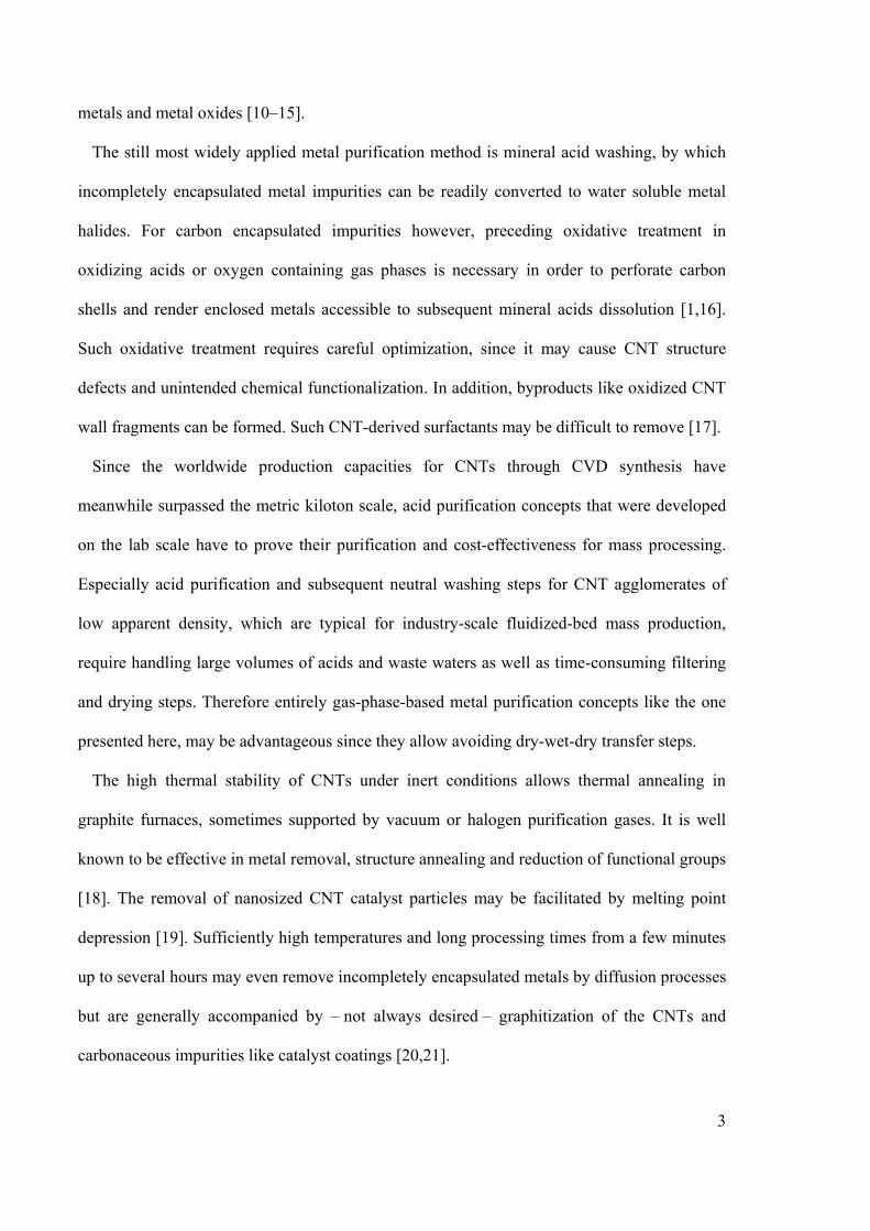
18
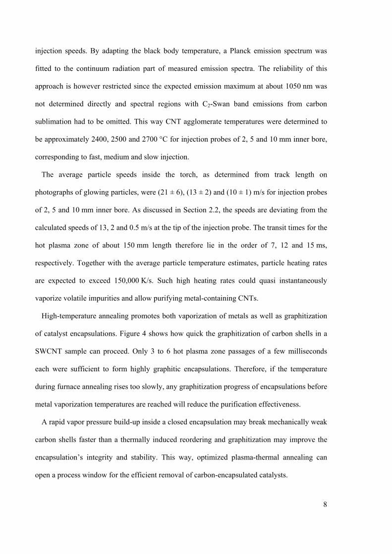
Figure 3: TEM pictures showing Elicarb® PR925 SWCNT samples before (A, B) and after (C,
D) plasma-thermal processing.
19
Figure 4: TEM pictures showing encapsulated catalysts in Elicarb® PR925 SWCNT
samples: (A) untreated; (B) after 3 and (C) after 6 plasma-thermal processing cycles.
20
C150P Fast Medium Slow C150HP Rem
ain
ing
ma
ssa
fte
ras
hin
g a
t 80
0°C
in
wt.
% 3.0%
2.5%
2.0%
1.5%
1.0%
0.5%
0.0%
Figure 5: Remaining ash mass of MWCNT agglomerates of type Baytubes® C150P after a
single plasma torch passage with varied injection speed compared to the starting material
C150P and to commercially metal-depleted C150HP after ashing at 800 °C in air. See text for
details and specification of fast, medium, and slow injection speed.
21
0
1
2
3
4
C150P 2006-11-15
(B2006)
1
(B3584)
2 Plasmabehandlungen
(B3584)
3
(B3586)
C150HP 2007-05-14
(B2022)
Co
nce
ntr
atio
nin
mg
/g (
wt.
‰)
Mg ‰
Al ‰
Co ‰
Mn ‰
C150P 1 passage 2 passages 3 passages C150HP MWCNT MWCNT
Figure 6: Remaining metal concentration in mg/g MWCNT mass after single, double and
triple plasma-thermal processing (torch passage) at medium injection speed (see text)
compared to the starting material Baytubes® C150P and commercially metal-depleted
C150HP as determined by ETV-ICP OES.
22
0
2
4
6
8
10
12
14
16
18
0 1 2 3 4 5 6
Fe concentration in mg/g (w
t.‰
)
Number of plasma torch passages
Low power ‐ Fe in mg/g
High power ‐ Fe in mg/g
Figure 7: Remaining iron concentration in mg/g SWCNT mass after different plasma-thermal
processing cycles (torch passage) at medium injection speed (see text) and low (12 kW, gray
line) as well as high (20 kW, black line) power conditions in comparison to the starting
material Elicarb® PR925 as determined by DC Arc OES.
23
-5
0
5
10
15
20
25
30
100 200 300 400 500 600 700 800 900
DT
G in
µg
/min
T in °C
DTG (B3657b)DTG (B3656b)DTG (B3655b)BT C150HPDTG (B2036)
12 kW
3 passages
2 passages
1 passage
C150HP MWCNT
C150P MWCNT
Figure 8: Differential thermogravimetry data of MWCNT samples after single, double and
triple plasma-thermal processing (torch passage) at 12 kW compared to the starting material
Baytubes® C150P and commercially metal-depleted C150HP acquired with a TGA heating
rate of 1 K/min in synthetic air.
24
-10
10
30
50
70
90
110
130
DT
G in
µg
/min
6 passages
3 passages
2 passages
1 passage
PR925 SWCNT
12 kW
-10
10
30
50
70
90
110
100 200 300 400 500 600 700 800 900
DT
G in
µg
/min
T in °C
3 passages
2 passages
1 passage
PR925 SWCNT
20 kW
Figure 9: Differential thermogravimetry data of SWCNT samples after plasma-thermal
processing (torch passage) at 12 kW (top) and 20 kW (bottom) plasma power compared to the
starting material Elicarb® PR925 acquired with a TGA heating rate of 10 K/min in synthetic
air.
25
0
0.001
0.002
0.003
0.004
0.005
0.006
0.007
1175 1275 1375 1475 1575 1675
Raman shift in 1/cm
<B2036> 0x <B3655b> 1x <B3656b> 2x <B3657b> 3x
GD
C150P 1 passage 2 passages 3 passages
No
rma
lize
dR
am
an
inte
ns
ity
Figure 10: Raman spectra of MWCNT samples after single, double and triple plasma-thermal
processing (torch passage) compared to the starting material Baytubes® C150P. The
measurements were taken at four different sample spots, averaged, scaled to an integral
intensity of 1 for the shown range and smoothed with a running mean of 2.5 wavenumbers bin
width.
26
0
0.005
0.01
0.015
0.02
0.025
1175 1275 1375 1475 1575 1675 1775 1875
Norm
alized Raman intensity
Raman Shift in 1/cm
PR925 SWCNT 1 passage 3 passages
Figure 11: Raman spectra of Elicarb® PR925 SWCNTs before and after single and triple
plasma-thermal processing (passage). The measurements were taken at four different sample
spots, averaged, scaled to an integral intensity of 1 in the range of 1175-1700 1/cm.
Related Documents