March 2001 Process Industry Practices Structural PIP STC01018 Blast Resistant Building Design Criteria

Welcome message from author
This document is posted to help you gain knowledge. Please leave a comment to let me know what you think about it! Share it to your friends and learn new things together.
Transcript
March 2001
Process Industry PracticesStructural
PIP STC01018Blast Resistant Building Design Criteria
PURPOSE AND USE OF PROCESS INDUSTRY PRACTICES
In an effort to minimize the cost of process industry facilities, this Practice hasbeen prepared from the technical requirements in the existing standards of majorindustrial users, contractors, or standards organizations. By harmonizing thesetechnical requirements into a single set of Practices, administrative, application, andengineering costs to both the purchaser and the manufacturer should be reduced. Whilethis Practice is expected to incorporate the majority of requirements of most users,individual applications may involve requirements that will be appended to and takeprecedence over this Practice. Determinations concerning fitness for purpose andparticular matters or application of the Practice to particular project or engineeringsituations should not be made solely on information contained in these materials. Theuse of trade names from time to time should not be viewed as an expression ofpreference but rather recognized as normal usage in the trade. Other brands having thesame specifications are equally correct and may be substituted for those named. AllPractices or guidelines are intended to be consistent with applicable laws andregulations including OSHA requirements. To the extent these Practices or guidelinesshould conflict with OSHA or other applicable laws or regulations, such laws orregulations must be followed. Consult an appropriate professional before applying oracting on any material contained in or suggested by the Practice.
This Practice is subject to revision at any time by the responsible Function Teamand will be reviewed every 5 years. This Practice will be revised, reaffirmed, orwithdrawn. Information on whether this Practice has been revised may be found athttp://www.pip.org.
© Process Industry Practices (PIP), Construction Industry Institute, TheUniversity of Texas at Austin, 3208 Red River Street, Suite 300, Austin,Texas 78705. PIP member companies and subscribers may copy this Practicefor their internal use.
Not printed with State funds
March 2001
Process Industry Practices Page 1 of 20
Process Industry PracticesStructural
PIP STC01018Blast Resistant Building Design Criteria
Table of Contents
1. Introduction..............................21.1 Purpose........................................... 21.2 Scope.............................................. 2
2. References ...............................22.1 Process Industry Practices ............. 22.2 Industry Codes and Standards........ 22.3 Other References............................ 3
3. Definitions ................................3
4. General .....................................54.1 Owner's Specific Data and
Requirements ................................. 54.2 Engineer's Responsibilities ............. 54.3 Documentation................................ 5
5. Basic Requirements ................65.1 Building Performance ..................... 65.2 Building Configuration .................... 65.3 Blast Loads..................................... 65.4 Construction and Materials............. 75.5 Material Properties ......................... 7
6. Structural Design.....................96.1 Design Methods and Procedures ... 96.2 Load Combinations......................... 96.3 Analysis Methods ......................... 10
6.4 Deformation Limits ....................... 116.5 Component Design....................... 126.6 Structural-Framing Design ........... 156.7 Foundation Design ....................... 15
7. Ancillary Items ....................... 167.1 Blast Doors ................................... 167.2 Windows....................................... 177.3 Openings ...................................... 187.4 Penetrations ................................. 187.5 Suspended Items ......................... 187.6 Externally Mounted Items............. 187.7 Equipment and Internally Mounted
Items............................................. 19
Appendix ABlast Design Requirements Data Sheet
Appendix BCommentary
PIP STC01018Blast Resistant Building Design Criteria March 2001
Page 2 of 20 Process Industry Practices
1. Introduction
1.1 Purpose
The purpose of this Practice is to establish structural design criteria for new blastresistant buildings, including requirements for selection of structural systems,analysis methods, and design of ancillary items such as doors and openings.
1.2 Scope
This Practice also contains design criteria for non-structural items (architectural,electrical, HVAC, etc.) that may influence the design of blast resistant buildings.
2. References
Applicable requirements in the latest edition (or edition indicated) of the following codes,standards, and references shall be considered an integral part of this Practice. The edition ineffect on the date of contract award shall be used, except as otherwise noted. Short titles willbe used herein when appropriate.
2.1 Process Industry Practices (PIP)
– PIP CVS02010 - Geotechnical Engineering Investigation Specification
– PIP STC01015 - Structural Design Criteria
– PIP STC01018 – Project Data Sheets
2.2 Industry Codes and Standards
• American Concrete Institute (ACI)
– ACI 318 - Building Code Requirements for Structural Concrete
– ACI 530 - Building Code Requirements for Masonry Structures
• American Institute of Steel Construction (AISC)
– Load and Resistance Factor Design Specification for Structural SteelBuildings (LRFD)
• American Iron and Steel Institute (AISI)
– Specification for the Design of Cold-Formed Steel Structural Members, Loadand Resistance Factor Design, Cold-Formed Steel Design Manual, 1997.
• American Society for Testing and Materials (ASTM)
– ASTM A36 - Standard Specification for Carbon Structural Steel
– ASTM A82 - Standard Specification for Steel Wire, Plain, for ConcreteReinforcement
– ASTM A653 - Standard Specification for Steel Sheet, Zinc-Coated(Galvanized) or Zinc-Iron Alloy-Coated (Galvannealed) by the Hot-DipProcess
PIP STC01018March 2001 Blast Resistant Building Design Criteria
Process Industry Practices Page 3 of 20
– ASTM A514 - Standard Specification for High-Yield-Strength, Quenched andTempered Alloy Steel Plate, Suitable for Welding
– ASTM A588 - Standard Specification for High-Strength Low-Alloy StructuralSteel with 50 ksi [345 MPa] Minimum Yield Point to 4 in. [100 mm] Thick
– ASTM A615 - Standard Specification for Deformed and Plain Billet-SteelBars for Concrete Reinforcement
– ASTM A706 - Standard Specification for Low-Alloy Steel Deformed and PlainBars for Concrete Reinforcement
– ASTM C90 - Standard Specification for Load-Bearing Concrete MasonryUnits
• International Conference of Building Officials (ICBO)
– Uniform Building Code (UBC), 1997 Edition
2.3 Other References
– ASCE - Design of Blast Resistant Buildings in Petrochemical Facilities,American Society of Civil Engineers (ASCE), 1997
– TM 5-1300 - Structures to Resist the Effects of Accidental Explosions, U.S.Dept. of the Army, 1990
3. Definitions
Angle of Incidence: The angle between the direction of the blast wave travel and a lineperpendicular to the surface of a structure at the point of interest
Blast Loads: The transient dynamic loads from the blast effects of an explosion, usuallystated in terms of peak pressure and impulse or duration
Conventional Loads: Loads applied in the conventional (non-blast) design of structuresincluding dead, live, wind, and seismic loads as required by local building codes. Theseloads are typically statically applied.
DIF (Dynamic Increase Factor): A multiplier applied to the static strength of a material toreflect the increased effective strength due to fast strain rates caused by rapidly applied blastloads
Ductility Ratio: A measure of the degree of plasticity in a member at maximum dynamicresponse, equal to the maximum displacement divided by the displacement at yield. Thisvalue is a key measure of dynamic response.
Duration: The length of time from start of the initial positive phase of the blast pressure tothe return to ambient pressure
Dynamic Reaction: The support reaction of a structural component to the dynamic blastloading, taking into account inertia effects
Engineer: The responsible professional in charge (Engineer-of-Record) of the blast resistantbuilding design
PIP STC01018Blast Resistant Building Design Criteria March 2001
Page 4 of 20 Process Industry Practices
Fragment Resistant: The resistance to high-speed fragments that result from the break up ofequipment or structures that are close to the explosion source
Free-Field Pressure: The rise in above-ambient pressure produced by a blast wave sweepingunimpeded across a surface not facing the blast source. This is also referred to as side-onpressure.
Impulse: A measure used, along with the peak blast pressure, to define the ability of a blastwave to do damage. Impulse is calculated as the integrated area under the positive pressurevs. duration curve and is shown in units of MPa-msec (psi-msec).
MDOF (Multi-Degree of Freedom): Representation of a structure or component as a spring-mass system with more than one degree of freedom
Multi-Unit Building: The building used for support of multiple process units, where losswould adversely impact several separate process units
Negative Phase: The portion of the pressure-time history typically following the positive(overpressure) phase in which the pressure is below ambient pressure (suction)
Nonlinear Response: Deformation of a component or system beyond the elastic limit
Period: The fundamental natural period of a structural component when modeled as a single-degree-of-freedom (SDOF) system
Positive Phase: The portion of the pressure-time history in which the pressure is aboveambient pressure
Rebound: The deformation in the direction opposing the initial blast pressure. This occursafter a component has reached a peak deformation and returns in the direction of its initialposition.
Reflected Pressure (Pr ): The rise in pressure above ambient produced by a shock wave orpressure wave striking a surface facing the direction of blast wave propagation
Response Range: The following descriptions apply to the response ranges mentioned in thisPractice
Low (L) - Localized building/component damage. Building can be used; howeverrepairs are required to restore integrity of structural envelope. Total cost of repairs ismoderate.
Medium (M) - Widespread building/component damage. Building cannot be useduntil repaired. Total cost of repairs is significant.
High (H) - Building/component has lost structural integrity and may collapse fromadditional environmental loads (i.e., wind, snow, and rain). Total cost of repairsapproach replacement cost of building.
SDOF (Single Degree of Freedom): Representation of a structure or component as a spring-mass system with one degree of freedom. Displacement of the SDOF system corresponds tothe displacement of a single point in the real system, typically corresponding to the point ofmaximum deflection.
PIP STC01018March 2001 Blast Resistant Building Design Criteria
Process Industry Practices Page 5 of 20
Side-On Pressure (Pso): The rise in pressure above ambient produced by a blast wavesweeping unimpeded across any surface (walls or roof) not facing the blast source. This isalso referred to as free-field or incident pressure.
SIF (Strength Increase Factor): A multiplier applied to the nominal strength properties of amaterial to reflect its actual strength above minimum specified values
Single-Unit Building: Building used for support/control of only one process unit
Support Rotation: The angle formed between the axis of a member loaded between itsendpoints and a straight line between one endpoint and the point of maximum deflection.This value is a key measure of dynamic response.
4. General
4.1 Owner’s Specific Data and Requirements
Data specific to each facility (building or project) to be used with this Practice shallbe specified in the PIP STC01018 Data Sheet (see Appendix A). The informationthat will be specified in the Data Sheet includes the following:
4.1.1 Blast Design Requirements
4.1.1.1 Building performance requirements and acceptable response range(low, medium, or high) (Refer to Section 6.4.3.)
4.1.1.2 Performance categories (I - IV) for blast resistant doors (Refer toTable 9.)
4.1.1.3 Blast loads specified as peak side-on positive pressure withcorresponding impulse or duration at the building (See Section 5.3.)
4.2 Engineer’s Responsibilities
4.2.1 Section 1.4 and Figure 1.1 of ASCE (1997) delineate information to beprovided by the Owner and tasks to be performed by the Engineer. Itemswith overlapping responsibility in the flowchart will be the ultimateresponsibility of the Engineer. The Engineer is responsible for producing adesign, using sound engineering principles, that meets the requirements ofthis Practice.
4.2.2 The Engineer shall be responsible for designing the facility to meet theperformance requirements specified in the Data Sheet. The Engineer shallbring any items requiring clarification to the Owner’s attention.
4.3 Documentation
4.3.1 A Data Sheet will be prepared for each blast resistant building, by or onbehalf of the Owner, and provided to the Engineer as a part of the job orproject specifications.
4.3.2 The final design shall be prepared by the Engineer and shall include thefollowing documentation:
PIP STC01018Blast Resistant Building Design Criteria March 2001
Page 6 of 20 Process Industry Practices
4.3.2.1 PIP STC01018 Data Sheet
4.3.2.2 Supporting calculations covering the design criteria, methodology,results, and the references and tools used
4.3.2.3 Detailed structural drawings and specifications for construction, asappropriate
5. Basic Requirements
5.1 Building Performance
The degree of structural damage permitted for blast resistant buildings, known as“building response range,” will be specified in the Data Sheet.
5.2 Building Configuration
Single-story construction shall be used where possible. Where multi-storyconstruction is required, the number of stories shall be minimized and special designconsiderations shall be given to the inter-story response to the blast loading.
The floor plan and elevation preferably shall have clean rectangular profiles withoutre-entrant corners, and recessed areas shall be minimized.
5.3 Blast Loads
Each blast resistant building shall be designed for the dynamic blast loads providedin the Data Sheet. Blast loads on individual building surfaces shall be computed bythe Engineer from the specified side-on pressure using the methods described inChapter 3 of ASCE (1997).
5.3.1 Component Loads
5.3.1.1 Structural components, doors, or appurtenance on an exterior surfaceof a blast resistant building shall be designed for the blast loadingapplicable to that surface. Specifically, each such component shallbe designed for any one of the following:
5.3.1.1.1 The direct tributary blast load applicable to the surface ofthe building on which it is located
5.3.1.1.2 The dynamic reaction to the blast load on a supportedcomponent, as appropriate
5.3.1.1.3 The ultimate load capacity of the supported component
5.3.1.2 Where the blast effects on an appurtenance to the building are oflittle consequence, the building component must still be designed forthe ultimate or “failure” load from such an appurtenance.
5.3.2 Foundation Load
The foundation for a blast resistant building shall be designed perSection 6.7 using any one of the following:
PIP STC01018March 2001 Blast Resistant Building Design Criteria
Process Industry Practices Page 7 of 20
5.3.2.1 The peak dynamic reactions from the supported superstructuretreated statically
5.3.2.2 The ultimate static capacity of the supported superstructure
5.3.2.3 The tributary area method. This method may be used in conjunctionwith the applied blast loads to determine foundation response usinga dynamic analysis method.
5.4 Construction and Materials
The structural system and materials shall be selected to provide the most economicaldesign that meets all performance requirements or as dictated by the Owner’sspecifications or architectural considerations.
5.4.1 Brittle Construction
Brittle construction, including unreinforced concrete, prestressed concrete,unreinforced masonry (block, brick, clay tile), poured gypsum, and cement-asbestos panels, shall not be used for load-carrying components of blastresistant buildings.
5.4.2 Advanced Materials
Advanced materials, such as composites, may be used if adequate test dataare available to confirm their satisfactory performance for the intendedapplication and if the Owner or Owner’s Representative gives prior writtenapproval. Such test data shall include the ultimate capacity and behavior ofthe material under dynamic conditions representative of blast loading.Satisfactory performance of the material under seismic condition is notsufficient to indicate blast capacity.
5.4.3 Fragment Resistance
Reinforced concrete or fully grouted reinforced masonry of appropriatestrength and thickness shall be used as cladding where fragment resistance isrequired per the Data Sheet.
5.5 Material Properties
5.5.1 Dynamic Material Strength
5.5.1.1 Dynamic yield stress, Fdy, shall be computed as follows:
Fdy = Fy * SIF * DIF
Fy is the specified minimum static yield stress; DIF is the dynamicincrease factor per Section 5.5.3; SIF is the strength increase factorper Section 5.5.2.
5.5.1.2 Dynamic design stress, Fds, used to compute the dynamic capacity
of structural components shall be based on the values listed inTables 4 and 5 for structural steel and reinforcing steel, respectively.
5.5.1.3 Dynamic ultimate strength, Fdu, shall be computed as follows:
PIP STC01018Blast Resistant Building Design Criteria March 2001
Page 8 of 20 Process Industry Practices
Fdu
= Fu * DIF
Fu is the specified ultimate strength; DIF is the dynamic increasefactor per Section 5.5.3.
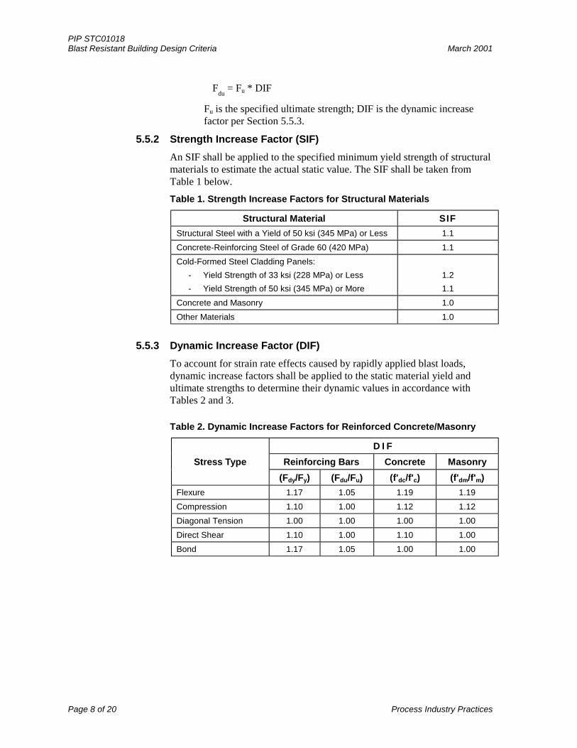
5.5.2 Strength Increase Factor (SIF)
An SIF shall be applied to the specified minimum yield strength of structuralmaterials to estimate the actual static value. The SIF shall be taken fromTable 1 below.
Table 1. Strength Increase Factors for Structural Materials
Structural Material SIF
Structural Steel with a Yield of 50 ksi (345 MPa) or Less 1.1
Concrete-Reinforcing Steel of Grade 60 (420 MPa) 1.1
Cold-Formed Steel Cladding Panels:
- Yield Strength of 33 ksi (228 MPa) or Less
- Yield Strength of 50 ksi (345 MPa) or More
1.2
1.1
Concrete and Masonry 1.0
Other Materials 1.0
5.5.3 Dynamic Increase Factor (DIF)
To account for strain rate effects caused by rapidly applied blast loads,dynamic increase factors shall be applied to the static material yield andultimate strengths to determine their dynamic values in accordance withTables 2 and 3.
Table 2. Dynamic Increase Factors for Reinforced Concrete/Masonry
D I F
Stress Type Reinforcing Bars Concrete Masonry
(Fdy/Fy) (Fdu/Fu) (f'dc/f'c) (f'dm/f'm)
Flexure 1.17 1.05 1.19 1.19
Compression 1.10 1.00 1.12 1.12
Diagonal Tension 1.00 1.00 1.00 1.00
Direct Shear 1.10 1.00 1.10 1.00
Bond 1.17 1.05 1.00 1.00
PIP STC01018March 2001 Blast Resistant Building Design Criteria
Process Industry Practices Page 9 of 20
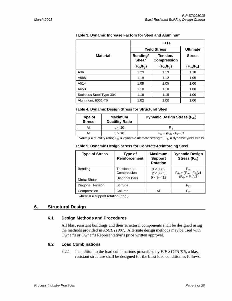
Table 3. Dynamic Increase Factors for Steel and Aluminum
D I F
Yield Stress Ultimate
Material Bending/Shear
Tension/Compression
Stress
(Fdy/Fy) (Fdy/Fy) (Fdu/Fu)
A36 1.29 1.19 1.10
A588 1.19 1.12 1.05
A514 1.09 1.05 1.00
A653 1.10 1.10 1.00
Stainless Steel Type 304 1.18 1.15 1.00
Aluminum, 6061-T6 1.02 1.00 1.00
Table 4. Dynamic Design Stress for Structural Steel
Type ofStress
MaximumDuctility Ratio
Dynamic Design Stress (Fds)
All µ < 10 Fdy
All µ > 10 Fdy + (Fdu - Fdy) /4
Note: µ = ductility ratio; Fdu = dynamic ultimate strength; Fdy = dynamic yield stress
Table 5. Dynamic Design Stress for Concrete-Reinforcing Steel
Type of Stress Type ofReinforcement
MaximumSupportRotation
Dynamic DesignStress (Fds)
Bending
Direct Shear
Tension andCompression
Diagonal Bars
0 < θ < 22 < θ < 5
5 < θ < 12
Fdy
Fdy + (Fdu - Fdy)/4(Fdy + Fdu)/2
Diagonal Tension Stirrups Fdy
Compression Column All Fdy
where θ = support rotation (deg.)
6. Structural Design
6.1 Design Methods and Procedures
All blast resistant buildings and their structural components shall be designed usingthe methods provided in ASCE (1997). Alternate design methods may be used withOwner’s or Owner’s Representative’s prior written approval.
6.2 Load Combinations
6.2.1 In addition to the load combinations prescribed by PIP STC01015, a blastresistant structure shall be designed for the blast load condition as follows:
PIP STC01018Blast Resistant Building Design Criteria March 2001
Page 10 of 20 Process Industry Practices
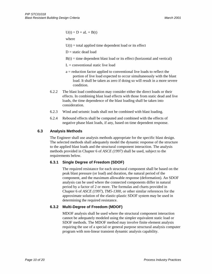
U(t) = D + aL + B(t)
where
U(t) = total applied time dependent load or its effect
D = static dead load
B(t) = time dependent blast load or its effect (horizontal and vertical)
L = conventional static live load
a = reduction factor applied to conventional live loads to reflect theportion of live load expected to occur simultaneously with the blastload. It shall be taken as zero if doing so will result in a more severecondition.
6.2.2 The blast load combination may consider either the direct loads or theireffects. In combining blast load effects with those from static dead and liveloads, the time dependence of the blast loading shall be taken intoconsideration.
6.2.3 Wind and seismic loads shall not be combined with blast loading.
6.2.4 Rebound effects shall be computed and combined with the effects ofnegative phase blast loads, if any, based on time dependent response.
6.3 Analysis Methods
The Engineer shall use analysis methods appropriate for the specific blast design.The selected methods shall adequately model the dynamic response of the structureto the applied blast loads and the structural component interaction. The analysismethods provided in Chapter 6 of ASCE (1997) shall be used, subject to therequirements below.
6.3.1 Single Degree of Freedom (SDOF)
The required resistance for each structural component shall be based on thepeak blast pressure (or load) and duration, the natural period of thecomponent, and the maximum allowable response (deformation). An SDOFanalysis can be used where the connected components differ in naturalperiod by a factor of 2 or more. The formulas and charts provided inChapter 6 of ASCE (1997), TM5-1300, or other similar references for theapproximate solution of the elastic-plastic SDOF system may be used indetermining the required resistance.
6.3.2 Multi-Degree of Freedom (MDOF)
MDOF analysis shall be used where the structural component interactioncannot be adequately modeled using the simpler equivalent static load orSDOF methods. The MDOF method may involve finite element analysisrequiring the use of a special or general purpose structural analysis computerprogram with non-linear transient dynamic analysis capability.
PIP STC01018March 2001 Blast Resistant Building Design Criteria
Process Industry Practices Page 11 of 20
6.4 Deformation Limits
6.4.1 Parameters
Structural members shall be designed on the basis of maximum response(deformation) consistent with the performance requirements or permissibledamage level specified in Table B1. Deformation limits shall be expressed asductility ratio (µ), support rotation (θ), or frame sidesway, as appropriate.
6.4.2 Building Response Range
The design response range or permissible damage level (low, medium, orhigh) shall be based on the building design requirements provided inTable B1.
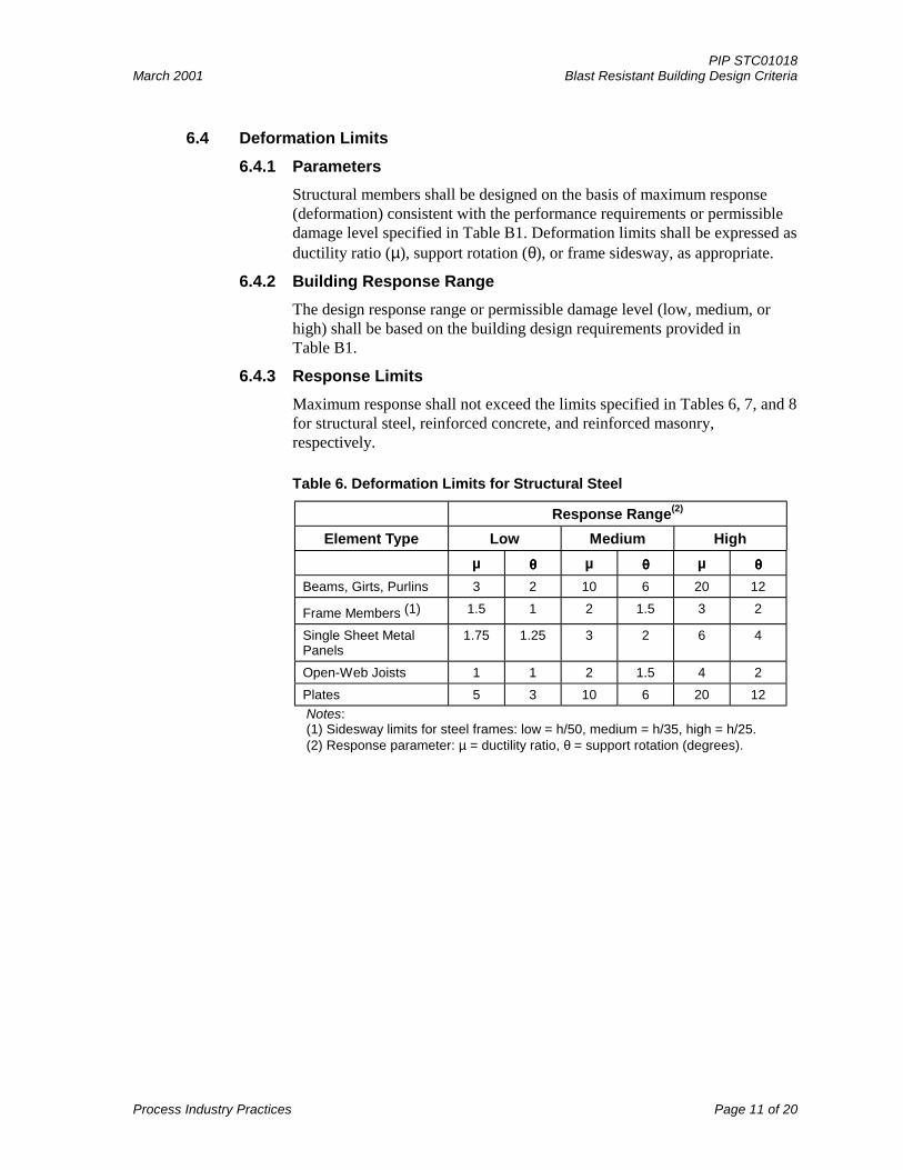
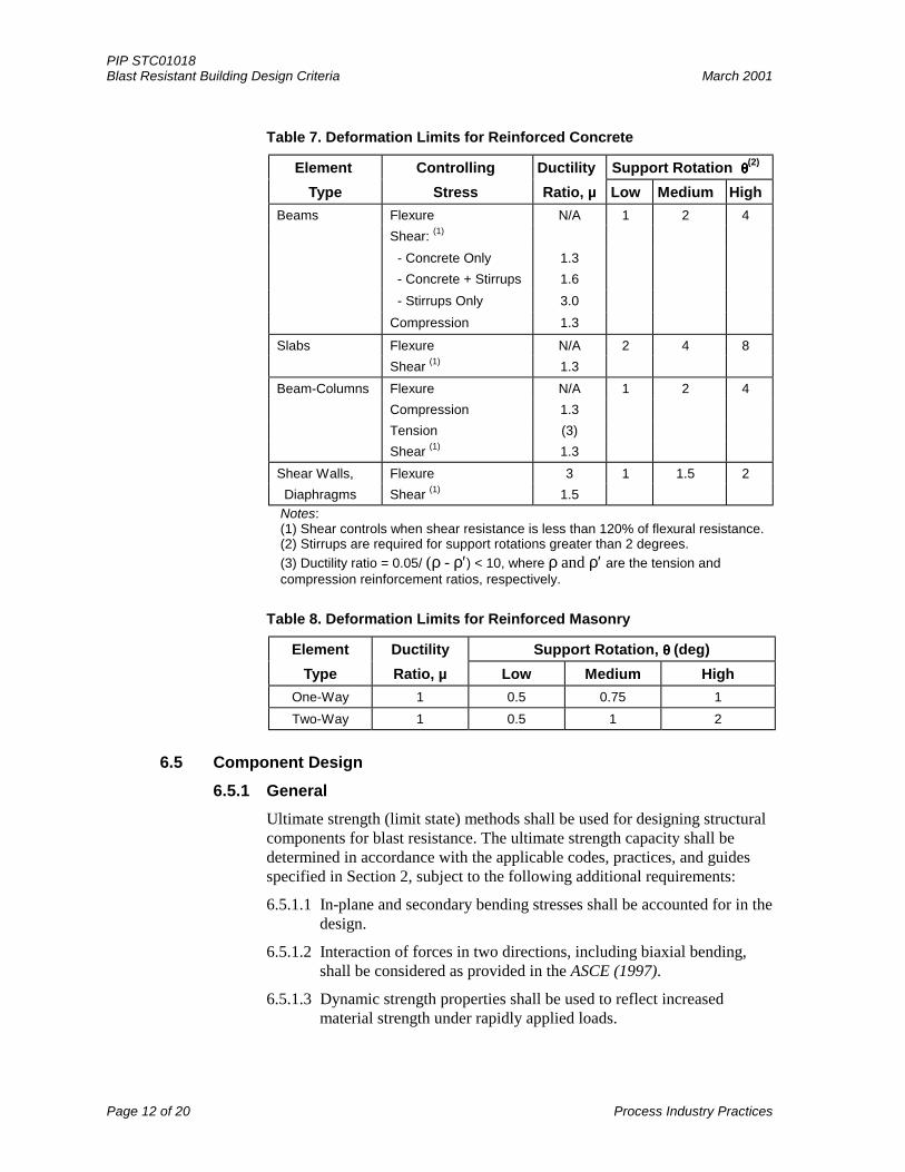
6.4.3 Response Limits
Maximum response shall not exceed the limits specified in Tables 6, 7, and 8for structural steel, reinforced concrete, and reinforced masonry,respectively.
Table 6. Deformation Limits for Structural Steel
Response Range(2)
Element Type Low Medium High
µ θθθθ µ θθθθ µ θθθθ
Beams, Girts, Purlins 3 2 10 6 20 12
Frame Members (1) 1.5 1 2 1.5 3 2
Single Sheet MetalPanels
1.75 1.25 3 2 6 4
Open-Web Joists 1 1 2 1.5 4 2
Plates 5 3 10 6 20 12
Notes:(1) Sidesway limits for steel frames: low = h/50, medium = h/35, high = h/25.(2) Response parameter: µ = ductility ratio, θ = support rotation (degrees).
PIP STC01018Blast Resistant Building Design Criteria March 2001
Page 12 of 20 Process Industry Practices
Table 7. Deformation Limits for Reinforced Concrete
Element Controlling Ductility Support Rotation θθθθ(2)
Type Stress Ratio, µ Low Medium High
Beams Flexure N/A 1 2 4
Shear: (1)
- Concrete Only 1.3
- Concrete + Stirrups 1.6
- Stirrups Only 3.0
Compression 1.3
Slabs Flexure N/A 2 4 8
Shear (1) 1.3
Beam-Columns Flexure N/A 1 2 4
Compression 1.3
Tension (3)
Shear (1) 1.3
Shear Walls, Flexure 3 1 1.5 2
Diaphragms Shear (1) 1.5 Notes:(1) Shear controls when shear resistance is less than 120% of flexural resistance.(2) Stirrups are required for support rotations greater than 2 degrees.
(3) Ductility ratio = 0.05/ (ρ - ρ′) < 10, where ρ and ρ′ are the tension andcompression reinforcement ratios, respectively.
Table 8. Deformation Limits for Reinforced Masonry
Element Ductility Support Rotation, θθθθ (deg)
Type Ratio, µ Low Medium High
One-Way 1 0.5 0.75 1
Two-Way 1 0.5 1 2
6.5 Component Design
6.5.1 General
Ultimate strength (limit state) methods shall be used for designing structuralcomponents for blast resistance. The ultimate strength capacity shall bedetermined in accordance with the applicable codes, practices, and guidesspecified in Section 2, subject to the following additional requirements:
6.5.1.1 In-plane and secondary bending stresses shall be accounted for in thedesign.
6.5.1.2 Interaction of forces in two directions, including biaxial bending,shall be considered as provided in the ASCE (1997).
6.5.1.3 Dynamic strength properties shall be used to reflect increasedmaterial strength under rapidly applied loads.
PIP STC01018March 2001 Blast Resistant Building Design Criteria
Process Industry Practices Page 13 of 20
6.5.1.4 Load and resistance factors shall be taken equal to 1.0 in all blastload combinations.
6.5.1.5 Composite sections may be used for design; however, adequaterebound resistance must be provided to ensure satisfactory responseunder rebound or negative phase loads.
6.5.1.6 Components shall be adequately laterally braced to preventpremature buckling failure during the positive and rebound response.
6.5.1.7 Connections shall be designed for 120% of the member’s controllingresistance (flexure or shear, whichever is lower). Except as noted forreinforced concrete members, the deformation limits indicated inTables 6, 7, and 8 are based on flexure-controlled resistance. To usethese limits, the member’s shear capacity shall be at least 120% ofthe flexural capacity.
6.5.1.8 Design for compression elements, such as load-bearing walls andcolumns, shall consider bending effects including p-delta andslenderness.
6.5.2 Reinforced Concrete
Reinforced concrete components shall be designed, using ultimate strengthmethods, in accordance with the provisions of ACI 318 and ASCE (1997).The following specific requirements shall also apply:
6.5.2.1 Deformation limits as noted for shear shall be used where themember’s shear capacity is less than 120% of the flexural capacity.
6.5.2.2 Except as specified in the contract documents, a minimum 4000 psi(28 MPa) concrete compressive strength is recommended for thedesign of the concrete structures.
6.5.2.3 Reinforcing steel shall conform to ASTM A706, except that A615Grade 60 (420 Mpa) may be used if the requirements of ACI 318,Section 21.2.5, are met. The maximum bar size shall be No. 10 (32mm).
6.5.2.4 Wall and roof components shall be designed for in-plane and out-of-plane loads that act simultaneously by using the following equation:
[∆c / ∆a]i2 [∆c / ∆a]o
2 < 1.0
where
∆c = computed deformation (ductility ratio or support rotation)
∆a = allowable deformation
i = in-plane
o = out-of-plane
6.5.2.5 Slenderness effects shall be included for load-bearing walls and formembers with significant axial loads.
PIP STC01018Blast Resistant Building Design Criteria March 2001
Page 14 of 20 Process Industry Practices
6.5.2.6 Support shall be provided for roof slab to prevent failure duringrebound. Headed studs may be used for this purpose; however, theyshall be located and spaced to minimize composite action unlesscomposite action is required and specifically designed for.
6.5.3 Structural Steel
Structural steel components shall be designed in accordance with theprovisions of AISC LRFD, supplemented by the following requirements.
6.5.3.1 Materials with a specified yield strength of 50 ksi (345 MPa) or lessshall be used for flexural design. Higher strength materials may beused where ductile behavior is not required.
6.5.3.2 Oversize holes shall not be used in connections that are part of thelateral force-resisting system.
6.5.3.3 Column base plates shall be designed to develop the peak memberreactions applied as a static load. Dynamic material properties maybe used for design of base plates.
6.5.3.4 Flexural members shall be laterally braced on both faces to provideconsistent moment capacity in both positive and rebound response.
6.5.4 Cold-Formed Steel
Cold-formed steel components shall be designed in accordance withAISI LRFD, supplemented by the following specific requirements.
6.5.4.1 Ultimate resistance shall be determined using a factor of 0.9 appliedto the plastic moment capacity.
6.5.4.2 Tensile membrane capacity of wall panels may be used if adequateanchorage of panel ends is provided.
6.5.4.3 Tensile membrane capacity of cold-formed girts and purlins may beutilized in the design if they are supported on the exterior face of aframe member and are continuous over three or more spans.
6.5.4.4 Oversize washers shall be provided for wall panel anchorage screwsto prevent failure caused by rebound or negative phase loads.
6.5.4.5 Symmetric, closed sections shall be used wherever possible.
6.5.5 Open Web Steel Joist (OWSJ)
Design of OWSJ for blast loads may be accomplished using published loadtables for static, working loads with appropriate factors applied to obtain theultimate capacities with the following limitations:
6.5.5.1 A 10% reduction in ultimate moment capacity shall be used and isrecommended unless special provisions are made to enhanceductility of the joist.
6.5.5.2 Lateral bracing shall be provided for the top and bottom chords asrequired to provide the necessary rebound resistance and positivemoment capacity.
PIP STC01018March 2001 Blast Resistant Building Design Criteria
Process Industry Practices Page 15 of 20
6.5.6 Reinforced Masonry
Design of reinforced masonry shall be in accordance with the ultimatestrength method in ACI 530, ACI 530.1, and the UBC supplemented by thefollowing specific requirements:
6.5.6.1 Hollow concrete masonry units (CMU) shall conform toASTM C90, Grade N, with a minimum compressive strength (fm) of
1500 psi (10.3 MPa).
6.5.6.2 All cells of hollow CMU shall be fully grouted.
6.5.6.3 Joint reinforcing shall meet the requirements of ASTM A82 with aminimum yield stress of 70 ksi (483 MPa) and a minimum ultimatestrength of 80 ksi (552 MPa).
6.5.6.4 Primary reinforcing bars shall conform to ASTM A706 except thatASTM A615 Grade 60 (420 MPa) may be used if the requirements ofACI 318, Section 21.2.5, are met.
6.5.6.5 Wall components subjected to in-plane and out-of-plane loads shallbe designed using the interaction equation given in Section 6.5.2.5.
6.6 Structural-Framing Design
Design of the overall structural-framing system shall include analysis of globalresponse including sidesway, overturning, and sliding. Sidesway analysis shall beperformed with and without leeward side (rear wall) blast loads.
6.7 Foundation Design
Foundation design shall be based on a geotechnical report per PIP CVS02010 andthe geotechnical data summarized in the Section A-4 of PIP STC01018 Data Sheet.Foundation components shall be designed per ASCE (1997) to resist the peakreactions produced by supported components resulting from the dead, live, and blastloads, treated either statically or dynamically, as noted below.
6.7.1 Static Analysis
Static application of the peak dynamic reactions from the wall and roofcomponents may be used to design supporting members and to computeoverturning and sliding effects. For blast load combinations, factors of safetyfor overturning shall be 1.2, and for sliding shall be 1.0.
6.7.2 Static Capacity
Foundations shall be designed using vertical and lateral soil capacities asfollows:
6.7.2.1 Vertical - 80% of the ultimate net soil-bearing capacity for shallowfoundations, including footings and mats. For piles and other deepfoundations, 80% of the ultimate static capacities in compressionand in tension may be used.
6.7.2.2 Lateral - Passive resistance of grade beams may be used to resistlateral loads if compacted fill is placed around the building
PIP STC01018Blast Resistant Building Design Criteria March 2001
Page 16 of 20 Process Industry Practices
perimeter. Frictional resistance of spread footings and floor gradeslabs shall be based on the coefficient of friction determined by thegeotechnical study. The normal force shall be taken as the sum ofthe dead loads and the vertical load associated with the ultimateresistance of the roof. Frictional resistance of floating slabs shall notbe used.
6.7.2.3 Where only passive resistance, frictional resistance, vertical piles, orbattered piles are used to support the lateral blast loading, theresistance shall be taken as 80% of the ultimate static value.However, if two or more of these resistances are used to support thelateral blast loads, the lateral capacity shall be limited to 67% of thecombined ultimate static resistance.
6.7.2.4 Foundation sliding may be permitted if it can be demonstrated thatall underground and aboveground utility, electrical, andinstrumentation lines entering and exiting the building have adequateflexibility to accommodate the slide.
6.7.3 Dynamic Analysis
To optimize the foundation design, its components may be analyzeddynamically for the calculated reaction-time history of the supportedcomponents. The required dynamic material properties of the foundationsoils, including resistance and stiffness, shall be determined on the basis ofan appropriate geotechnical investigation. No deformation limits arespecified for dynamic response of foundations. The Engineer shall determinewhether the predicted maximum response is acceptable for the permissibledamage level of the building.
7. Ancillary Items
7.1 Blast Doors
Blast resistant doors shall be provided according to the following:
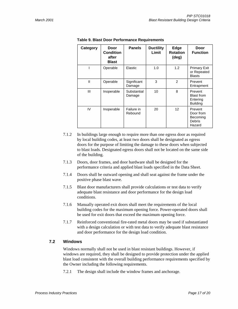
7.1.1 The performance category for the blast resistant doors shall be as specifiedin the Data Sheet. The response limits and other requirements shall be asgiven in Table 9.
PIP STC01018March 2001 Blast Resistant Building Design Criteria
Process Industry Practices Page 17 of 20
Table 9. Blast Door Performance Requirements
Category DoorCondition
afterBlast
Panels DuctilityLimit
EdgeRotation
(deg)
DoorFunction
I Operable Elastic 1.0 1.2 Primary Exitor RepeatedBlasts
II Operable SignificantDamage
3 2 PreventEntrapment
III Inoperable SubstantialDamage
10 8 PreventBlast fromEnteringBuilding
IV Inoperable Failure inRebound
20 12 PreventDoor fromBecomingDebrisHazard
7.1.2 In buildings large enough to require more than one egress door as required
by local building codes, at least two doors shall be designated as egressdoors for the purpose of limiting the damage to these doors when subjectedto blast loads. Designated egress doors shall not be located on the same sideof the building.
7.1.3 Doors, door frames, and door hardware shall be designed for theperformance criteria and applied blast loads specified in the Data Sheet.
7.1.4 Doors shall be outward opening and shall seat against the frame under thepositive phase blast wave.
7.1.5 Blast door manufacturers shall provide calculations or test data to verifyadequate blast resistance and door performance for the design loadconditions.
7.1.6 Manually operated exit doors shall meet the requirements of the localbuilding codes for the maximum opening force. Power-operated doors shallbe used for exit doors that exceed the maximum opening force.
7.1.7 Reinforced conventional fire-rated metal doors may be used if substantiatedwith a design calculation or with test data to verify adequate blast resistanceand door performance for the design load condition.
7.2 Windows
Windows normally shall not be used in blast resistant buildings. However, ifwindows are required, they shall be designed to provide protection under the appliedblast load consistent with the overall building performance requirements specified bythe Owner including the following requirements.
7.2.1 The design shall include the window frames and anchorage.
PIP STC01018Blast Resistant Building Design Criteria March 2001
Page 18 of 20 Process Industry Practices
7.2.2 Acceptable products include properly designed laminated glass, temperedglass, and polycarbonates. Product performance shall be substantiated by testdata.
7.3 Openings
Large openings in the building envelope, such as intake ducts, shall be designed toprevent entry of excessive blast pressures.
7.3.1 Blast valves, blast attenuators, or other devices shall be used to limitexcessive blast pressure entry into the structure. Performance of the blastvalve or attenuator shall be substantiated by test data and calculation.
7.3.2 Blast valves shall be provided for openings greater than 150 inch2
(1000 cm2) in any surface in which the peak applied pressure is greater than10 psi (0.07 MPa). Blast attenuators may be used for these openings if thepeak applied pressure is greater than 5 psi (0.035 MPa).
7.4 Penetrations
7.4.1 Wall and roof penetrations in reinforced concrete and masonry shall besleeved. Sleeves shall be anchored with a minimum of two (2) each 1/2-inchdiameter x 4-inch (12-mm diameter x 100-mm) long headed studs.
7.4.2 Penetrations in metal-clad structures shall be anchored with substantialframing attached to structural steel members.
7.5 Suspended Items
Equipment and furnishings such as ceilings, HVAC ductwork, and light fixturessuspended from the roof inside the building shall be secured to structural framingmembers. Anchorage shall be designed to resist a statically applied force equal to themass of the item times the maximum acceleration of the roof or five (5) times theweight of the item, whichever is less.
7.6 Externally Mounted Items
7.6.1 To avoid the potential for hazardous debris, large non-structural featuressuch as canopies and signs on the building exterior should be minimized.However, small items such as instruments, fire alarms, lights, strobes, andbeacons may be mounted on the exterior walls.
7.6.2 Roof- and wall-mounted equipment (e.g., HVAC equipment) should beavoided. If approved by Owner or Owner’s Representative, such equipmentshall be securely anchored and the supporting structural components shall bespecifically designed for actual equipment dynamic loads when subjected tothe blast.
7.6.3 Equipment and other items mounted on the exterior surfaces (walls or roof)of the building shall be designed similarly to the structural components ifthey are to withstand the applied blast loads. The reactions from such itemsshall be considered in the design of the supporting structural components.
PIP STC01018March 2001 Blast Resistant Building Design Criteria
Process Industry Practices Page 19 of 20
7.7 Equipment and Internally Mounted Items
7.7.1 Instrumentation or electrical equipment shall not be mounted on the interiorface of walls subjected to blast loads without Owner or Owner’sRepresentative’s prior written approval.
7.7.2 All fixed floor-supported items, such as lockers, electrical cabinets, racks,etc., shall have a minimum clearance from exterior walls equal to themaximum calculated lateral blast load deflection. The maximum deflectionshall consider both the overall building sidesway plus deflection of any wallcomponent(s) and shall be computed based on the maximum blast loadsdefined in the Data Sheet. Supports and anchorage for such equipment shallbe designed to resist a lateral force equal to 20% of the equipment weight.

PIP STC01018Blast Resistant Building Design Criteria March 2001
Page 20 of 20 Process Industry Practices
This page is intentionally left blank.
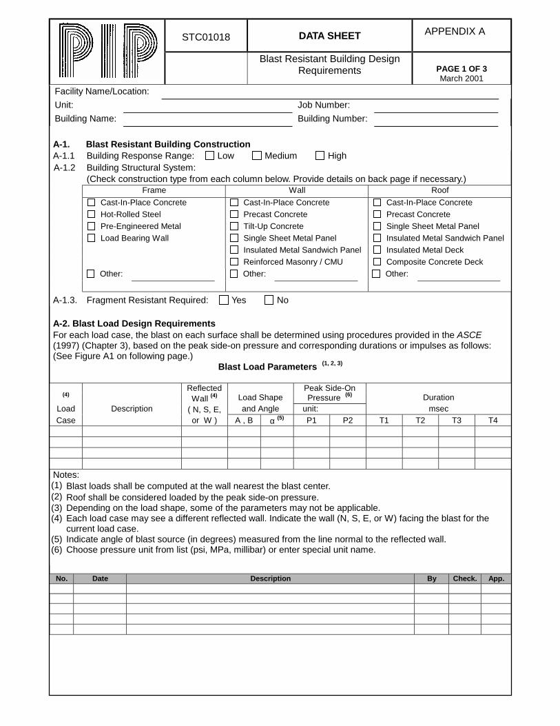
STC01018 DATA SHEET APPENDIX A
Blast Resistant Building DesignRequirements PAGE 1 OF 3
March 2001
Facility Name/Location:
Unit: Job Number:
Building Name: Building Number:
A-1. Blast Resistant Building ConstructionA-1.1 Building Response Range: Low Medium HighA-1.2 Building Structural System:
(Check construction type from each column below. Provide details on back page if necessary.)Frame Wall Roof
Cast-In-Place Concrete Cast-In-Place Concrete Cast-In-Place Concrete
Hot-Rolled Steel Precast Concrete Precast Concrete
Pre-Engineered Metal Tilt-Up Concrete Single Sheet Metal Panel
Load Bearing Wall Single Sheet Metal Panel Insulated Metal Sandwich Panel
Insulated Metal Sandwich Panel Insulated Metal Deck
Reinforced Masonry / CMU Composite Concrete Deck
Other: Other: Other:
A-1.3. Fragment Resistant Required: Yes No
A-2. Blast Load Design RequirementsFor each load case, the blast on each surface shall be determined using procedures provided in the ASCE(1997) (Chapter 3), based on the peak side-on pressure and corresponding durations or impulses as follows:(See Figure A1 on following page.)
Blast Load Parameters (1, 2, 3)
Reflected Peak Side-On(4)
Wall (4) Load Shape Pressure (6) DurationLoad Description ( N, S, E, and Angle unit: msec
Case or W ) A , B α (5) P1 P2 T1 T2 T3 T4
Notes:(1) Blast loads shall be computed at the wall nearest the blast center.(2) Roof shall be considered loaded by the peak side-on pressure.(3) Depending on the load shape, some of the parameters may not be applicable.(4) Each load case may see a different reflected wall. Indicate the wall (N, S, E, or W) facing the blast for the
current load case.(5) Indicate angle of blast source (in degrees) measured from the line normal to the reflected wall.(6) Choose pressure unit from list (psi, MPa, millibar) or enter special unit name.
No. Date Description By Check. App.
STC01018 DATA SHEET APPENDIX A
Blast Resistant Building DesignRequirements PAGE 2 OF 3
March 2001
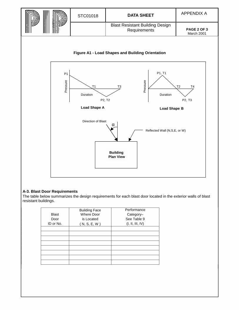
Figure A1 - Load Shapes and Building Orientation
A-3. Blast Door RequirementsThe table below summarizes the design requirements for each blast door located in the exterior walls of blastresistant buildings.
Building Face PerformanceBlast Where Door Category–Door is Located See Table 9
ID or No. ( N, S, E, W ) (I, II, III, IV)
Pre
ssur
e
BuildingPlan View
Load Shape A Load Shape B
Pre
ssur
e
αReflected Wall (N,S,E, or W)
Direction of Blast
Duration Duration
P1
P2, T2
P1, T1
T2
P2, T3
T4T3T1
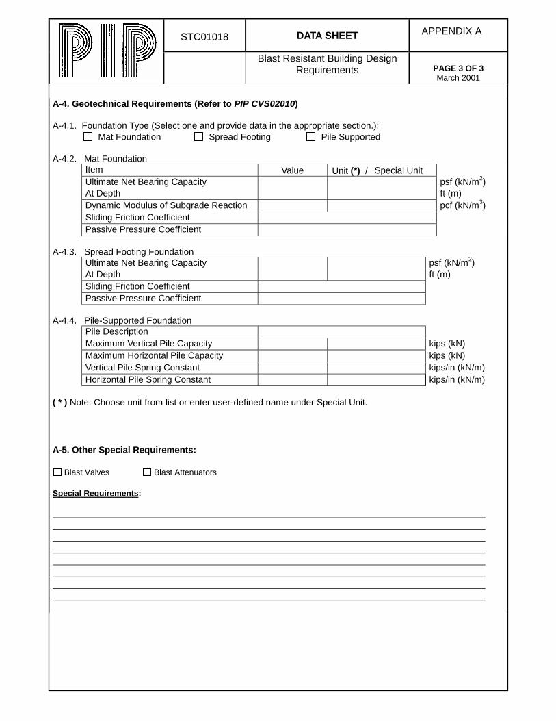
STC01018 DATA SHEET APPENDIX A
Blast Resistant Building DesignRequirements PAGE 3 OF 3
March 2001
A-4. Geotechnical Requirements (Refer to PIP CVS02010)
A-4.1. Foundation Type (Select one and provide data in the appropriate section.): Mat Foundation Spread Footing Pile Supported
A-4.2. Mat FoundationItem Value Unit (*) / Special UnitUltimate Net Bearing Capacity psf (kN/m2)At Depth ft (m)Dynamic Modulus of Subgrade Reaction pcf (kN/m3)Sliding Friction Coefficient Passive Pressure Coefficient
A-4.3. Spread Footing FoundationUltimate Net Bearing Capacity psf (kN/m2)At Depth ft (m)Sliding Friction Coefficient Passive Pressure Coefficient
A-4.4. Pile-Supported FoundationPile Description Maximum Vertical Pile Capacity kips (kN)Maximum Horizontal Pile Capacity kips (kN)Vertical Pile Spring Constant kips/in (kN/m)Horizontal Pile Spring Constant kips/in (kN/m)
( * ) Note: Choose unit from list or enter user-defined name under Special Unit.
A-5. Other Special Requirements:
Blast Valves Blast Attenuators
Special Requirements:

This page is intentionally left blank.

PIP STC01018March 2001 Blast Resistant Building Design Criteria
APPENDIX B – COMMENTARY

This page is intentionally left blank.
PIP STC01018March 2001 Blast Resistant Building Design Criteria
Process Industry Practices B-1
Table of Contents
B-1 Introduction ....................... B-2B-1.1 Purpose ....................................B-2B-1.2 Scope .......................................B-2
B-2 References......................... B-3
B-3 Definitions ......................... B-3
B-4 General............................... B-3B-4.1 Owner-Specific Data and
Requirements .............................B-3B-4.2 Engineer's Responsibilities.......B-3B-4.3 Documentation .........................B-4
B-5 Basic Requirements.......... B-4B-5.1 Building Performance ...............B-4B-5.2 Building Configuration ..............B-4B-5.3 Blast Loads...............................B-5
B-5.3.1 Component Loads.........B-6B-5.4 Construction and Materials.......B-7
B-5.4.1 General .........................B-8B-5.4.3 Fragment Resistance ..B-10
B-5.5 Material Properties .................B-10B-5.5.1 Dynamic Material
Strength .....................B-10B-5.5.2 Strength Increase
Factor ........................B-10B-5.5.3 Dynamic Increase
Factor ........................B-10
B-6 Structural Design ............ B-11B-6.1 Design Methods and
Procedures ................................B-11B-6.2 Load Combinations ................B-13B-6.3 Analysis Methods ...................B-13
B-6.3.1a SDOF - Approximate SolutionB-13
B-6.3.1b SDOF - Numerical IntegrationB-14
B-6.3.2 MDOF..........................B-14B-6.4 Deformation Limits .................B-15
B-6.4.1 Response Parameters B-15B-6.4.2 Building Response
Range........................B-16B-6.5 Component Design.................B-16
B-6.5.1 General .......................B-16B-6.5.2 Reinforced Concrete ...B-17B-6.5.3 Structural Steel............B-17B-6.5.4 Cold-Formed Steel ......B-17
B-6.5.5 Open Web Steel Joists(OWSJ) ..................... B-18
B-6.5.6 Reinforced Masonry.... B-18B-6.6 Structural Framing..................B-18B-6.7 Foundation Design .................B-19
B-7 Ancillary Items ................ B-19B-7.1 Blast Doors.............................B-19B-7.2 Windows.................................B-19B-7.3 Openings................................B-20B-7.4 Penetrations ...........................B-20B-7.5 Suspended Items ...................B-20
B-8 References ...................... B-20
List of TablesTable B1. Building Performance
Requirements ..............................B-4Table B2. Building Classification
Matrix...........................................B-6Table B3. Construction Type Matrix...B-8Table B4. Response Range
Descriptions...............................B-16
List of FiguresFigure B1. Yield, Ultimate, and Design
Stresses ...................................B-10Figure B2. Overall Blast Resistant
Design Process ........................B-12Figure B3. Definition of Support
Rotation ....................................B-16
PIP STC01018Blast Resistant Building Design Criteria March 2001
Page B-2 Process Industry Practices
B-1 Introduction
B-1.1 Purpose
This recommended Practice focuses on the structural design of blast resistantbuildings to be performed by a structural engineering professional (Engineer). It isexpected that the requirements for the conventional and the non-structural(architectural, electrical, HVAC, etc.) designs of such buildings will be coveredseparately by the Owner.
This commentary to the recommended Practice provides additional informationregarding the selection and application of the blast design requirements. Thecommentary is not a part of the design requirements but is intended to assist theOwner and Engineer in applying the criteria during the course of the design.
B-1.2 Scope
This recommended Practice is meant to cover new facilities when the Owner invokesit. It does not specifically address existing facilities; however, the methods discussedare applicable to analysis of existing buildings and the design of retrofits for suchbuildings. The Engineer should refer to the ASCE(1) for specific guidance on analysisof existing facilities.
Some buildings may not require design for blast for a variety of reasons, includingnegligible blast loads levels or non-essential functions, or they may not be occupiedaccording to the Owner’s occupancy criteria. The Owner should determine whetherblast design is required for each facility and specify this in the project or jobspecifications.
A common issue related to design of structures at petrochemical facilities is thelower limit of overpressure below which blast resistant design is not required. Manycompanies have cutoffs ranging from 0.5 psi (3.4 kPa) to 1.0 psi (6.9 kPa) free-fieldoverpressure. This load level will produce damage to conventional buildings, withdamage ranging from cosmetic to moderate requiring repair for continued use.
The most rational approach is to design each building at a site for the predicted blastload developed in hazard analysis studies. However, this may not always bepractical, in which case an acceptable lower bound overpressure level must beestablished for conventional construction below which blast design need not beconsidered.
Building occupancy may be used in determining the need for blast resistance in newor existing buildings. However, this recommended Practice does not coveroccupancy criteria, which are addressed in other industry guidelines such asAPI 752(2).
Application of this recommended Practice on blast design may be influenced byfuture plant or process unit development. A building may be at risk at some point inthe future if a process unit is modified or if a new unit is added that can producehigher overpressures at a given structure. A master plan for facility siting is highlydesirable to address this issue.
PIP STC01018March 2001 Blast Resistant Building Design Criteria
Process Industry Practices B-3
B-2 References
The Reference section of this Commentary lists the documents that are to be used with orreferenced by this Practice. The recommended Practice is based primarily on the designmethods and procedures provided in ASCE(1). However, other similar references andguidelines may be used. There are a number of other applicable references for design of blastresistant structures, including those developed for U.S. Department of Defense purposes.One of the most widely used of these references, TM 5-1300(3), is also applicable topetrochemical facilities. However, the ASCE(1) is a “how to” document, which covers allaspects of blast design for buildings at petrochemical plants.
This Commentary lists additional references relevant to blast resistant design. Two of theseare earlier petroleum industry blast design criteria/guides, SG-22(4) and CIA (5), which havebeen widely used for a number of years. These documents provide requirements for design ofnew facilities but are based on TNT-equivalent blast loads and the equivalent static loaddesign method. They do not cover the more accurate design methods, the more complexforms of blast loads, or the structural design tools, which are now available and commonlyused.
B-3 Definitions
The terminology used in this Practice is consistent with ASCE(1) and other blast designmanuals such as TM 5-1300(3) and ASCE Manual 42(6). Some differences in definitions,especially for symbols, may exist in blast load prediction manuals. The Engineer shouldverify any conflicting definitions.
B-4 General
B-4.1 Owner-Specific Data and Requirements
In addition to the need for blast resistance, this Practice requires that the Ownerprovide certain data and requirements to the Engineer performing the design in thePIP STC01018 Data Sheet. The Data Sheet is provided as Appendix A to thisPractice.
B-4.2 Engineer’s Responsibilities
The Engineer is responsible for designing a structure that provides protection inaccordance with the response criteria based on the building performancerequirements provided by the Owner or defined in this Practice. In situations forwhich a particular blast protection requirement is not covered in this Practice,conservative design assumptions should be made to ensure safety. The Owner shouldcover topics or issues not addressed. The Engineer should bring items requiringclarification to the Owner’s attention as soon as possible to avoid project delays.
PIP STC01018Blast Resistant Building Design Criteria March 2001
Page B-4 Process Industry Practices
B-4.3 Documentation
The Data Sheet should completely describe the design criteria, blast loads, structuralsystem, and ancillary equipment. Material and section properties should be tabulatedto aid in future evaluation of alternate blast loads.
B-5 Basic Requirements
B-5.1 Building Performance
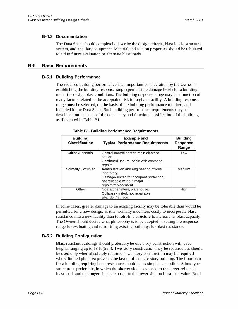
The required building performance is an important consideration by the Owner inestablishing the building response range (permissible damage level) for a buildingunder the design blast conditions. The building response range may be a function ofmany factors related to the acceptable risk for a given facility. A building responserange must be selected, on the basis of the building performance required, andincluded in the Data Sheet. Such building performance requirements may bedeveloped on the basis of the occupancy and function classification of the buildingas illustrated in Table B1.
Table B1. Building Performance Requirements
BuildingClassification
Example andTypical Performance Requirements
BuildingResponse
RangeCritical/Essential Central control center, main electrical
station.Continued use; reusable with cosmeticrepairs
Low
Normally Occupied Administration and engineering offices,laboratory.Damage-limited for occupant protection;not reusable without majorrepairs/replacement
Medium
Other Operator shelters, warehouse.Collapse-limited; not repairable;abandon/replace
High
In some cases, greater damage to an existing facility may be tolerable than would bepermitted for a new design, as it is normally much less costly to incorporate blastresistance into a new facility than to retrofit a structure to increase its blast capacity.The Owner should decide what philosophy is to be adopted in setting the responserange for evaluating and retrofitting existing buildings for blast resistance.
B-5.2 Building Configuration
Blast resistant buildings should preferably be one-story construction with eaveheights ranging up to 18 ft (5 m). Two-story construction may be required but shouldbe used only when absolutely required. Two-story construction may be requiredwhere limited plot area prevents the layout of a single-story building. The floor planfor a building requiring blast resistance should be as simple as possible. A box typestructure is preferable, in which the shorter side is exposed to the larger reflectedblast load, and the longer side is exposed to the lower side-on blast load value. Roof
PIP STC01018March 2001 Blast Resistant Building Design Criteria
Process Industry Practices B-5
overhangs, canopies, and re-entrant corners should be avoided where possible toavoid additional blast wave reflections. Architectural items such as canopies andsigns should be designed with light construction materials, such as canvas, to avoidcreating a debris hazard for the structure.
B-5.3 Blast Loads
This recommended Practice does not cover development of explosion scenarios orprediction of blast loads, which therefore remain for the Owner to determine.Methods for blast load prediction and considerations for determining the design basis
accident scenarios are provided(6 to 10).
The Owner should specify the design blast load data in the Data Sheet (seeAppendix A). As a minimum, the free-field overpressure at the building location
should be provided. The Engineer may use the procedures provided in ASCE(1) tocalculate the component blast loads on the basis of given free-field blast effects. TheOwner may also provide more detailed information from a site-specific study,including the side-on or reflected pressure-time profile and orientation (angle ofincidence) of the blast loading on each surface of the building. In this case, theEngineer should verify the location of the point of reference for the design blastloads. If sufficient information is available, including the location of the explosionreference point (epicenter) and the attenuation of the blast effects with distance fromthis point, variation of the blast load over the surfaces of the structure may beaccounted for in the design.
Generally there are three approaches to specifying blast load for designing newfacilities:
1. Using existing code/industry practice (default) values such as provided in
SG-22(4) and the UK CIA (5) Guide
2. Establishing company generic values
3. Basing the blast loads on site- or facility-specific explosion hazard studies
In some situations, it is appropriate to develop site- and building-specific blast loadson the basis of potential explosion hazards from any existing, planned, or futurefacilities. Default or generic blast loads are not based on the specific site hazard buton certain standard conditions such as spacing, process unit size, and hazard level. Inaddition, if the building location is not determined or if sufficient processinformation and physical configuration of the process unit is not available, the blastloads can only be approximated. In these situations, generic blast loads may beappropriate. Such loads may be based on a building category or classificationdefined by its occupancy or function following a blast and the separation distancefrom a potential explosion hazard, as illustrated in Table B2.
PIP STC01018Blast Resistant Building Design Criteria March 2001
Page B-6 Process Industry Practices
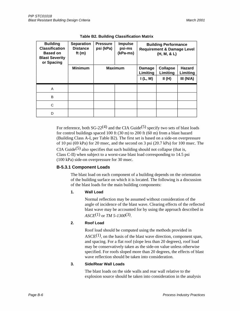
Table B2. Building Classification Matrix
BuildingClassification
Based onBlast Severity
or Spacing
SeparationDistance
ft (m)
Pressurepsi (kPa)
Impulsepsi-ms
(kPa-ms)
Building PerformanceRequirement & Damage Level
(H, M, & L)
Minimum Maximum DamageLimiting
CollapseLimiting
HazardLimiting
I (L, M) II (H) III (N/A)
A
B
C
D
For reference, both SG-22(4) and the CIA Guide(5) specify two sets of blast loadsfor control buildings spaced 100 ft (30 m) to 200 ft (60 m) from a blast hazard(Building Class A-I, per Table B2). The first set is based on a side-on overpressureof 10 psi (69 kPa) for 20 msec, and the second on 3 psi (20.7 kPa) for 100 msec. The
CIA Guide(5) also specifies that such building should not collapse (that is,Class C-II) when subject to a worst-case blast load corresponding to 14.5 psi(100 kPa) side-on overpressure for 30 msec.
B-5.3.1 Component Loads
The blast load on each component of a building depends on the orientationof the building surface on which it is located. The following is a discussionof the blast loads for the main building components:
1. Wall Load
Normal reflection may be assumed without consideration of theangle of incidence of the blast wave. Clearing effects of the reflectedblast wave may be accounted for by using the approach described in
ASCE(1) or TM 5-1300(3).
2. Roof Load
Roof load should be computed using the methods provided in
ASCE(1), on the basis of the blast wave direction, component span,and spacing. For a flat roof (slope less than 20 degrees), roof loadmay be conservatively taken as the side-on value unless otherwisespecified. For roofs sloped more than 20 degrees, the effects of blastwave reflection should be taken into consideration.
3. Side/Rear Wall Loads
The blast loads on the side walls and rear wall relative to theexplosion source should be taken into consideration in the analysis
PIP STC01018March 2001 Blast Resistant Building Design Criteria
Process Industry Practices B-7
of the overall building. These loads may be computed using the
methods given in Chapter 3 of ASCE(1) or may be conservativelyassumed to be the side-on values.
4. Overall Building (Frame) Loads
The overall structural framing should be designed for net verticaland lateral blast loads acting on the building, taking into account the
time phasing of these loads, as provided in ASCE(1).
The blast load on the rear face may be used to reduce the net lateralload for design of the overall structural framing system includingdiaphragm, shear walls, and foundation. The rear wall blast loadmay be ignored when this produces a more conservative design.However, if the rear wall loading is considered in the overall lateralblast loading, the lag time (delay in time of arrival) should be takeninto consideration.
5. Negative Phase (Suction) Load
A negative phase load following the positive (overpressure) phasemay be considered in the design if specified by the Owner. Theeffects of such a load should be considered in combination with therebound effect from the direct blast pressure load.
B-5.4 Construction and Materials
A wide choice of construction types is available for blast resistant buildings, rangingfrom conventional construction to bunker-like concrete structures. The constructiontype is typically dictated by such factors as cost, blast load level, local practice,
architectural considerations, and Owner preference. ASCE(1) (Chapter 4) describessome of the common types of construction used for blast resistant buildings inpetrochemical plants.
Conventionally designed buildings can provide some level of protection against blastloads. The degree of protection provided depends on the ductility and redundancy ofthe structure. Ductile structures, such as metal frame/metal clad, can typicallyrespond well into the plastic range and absorb blast energy. If connections are robust,components can develop tensile membrane action, which significantly increases theircapability to resist load.
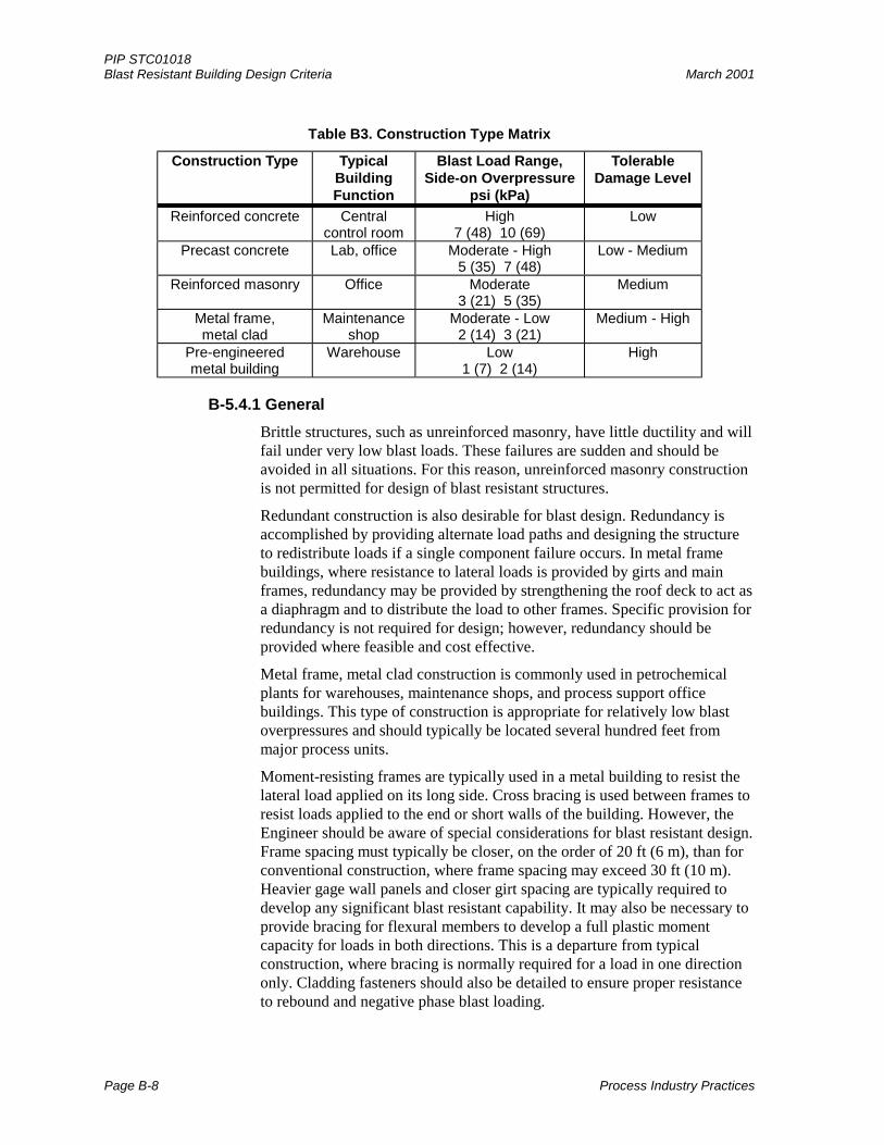
Table B3 lists some common types of building construction in the petrochemicalindustry, typical building function/use, the blast load ranges for each type ofconstruction, and the tolerable damage level appropriate for the buildingfunction/use.
PIP STC01018Blast Resistant Building Design Criteria March 2001
Page B-8 Process Industry Practices
Table B3. Construction Type Matrix
Construction Type TypicalBuildingFunction
Blast Load Range,Side-on Overpressure
psi (kPa)
TolerableDamage Level
Reinforced concrete Centralcontrol room
High7 (48) 10 (69)
Low
Precast concrete Lab, office Moderate - High5 (35) 7 (48)
Low - Medium
Reinforced masonry Office Moderate3 (21) 5 (35)
Medium
Metal frame,metal clad
Maintenanceshop
Moderate - Low2 (14) 3 (21)
Medium - High
Pre-engineeredmetal building
Warehouse Low1 (7) 2 (14)
High
B-5.4.1 General
Brittle structures, such as unreinforced masonry, have little ductility and willfail under very low blast loads. These failures are sudden and should beavoided in all situations. For this reason, unreinforced masonry constructionis not permitted for design of blast resistant structures.
Redundant construction is also desirable for blast design. Redundancy isaccomplished by providing alternate load paths and designing the structureto redistribute loads if a single component failure occurs. In metal framebuildings, where resistance to lateral loads is provided by girts and mainframes, redundancy may be provided by strengthening the roof deck to act asa diaphragm and to distribute the load to other frames. Specific provision forredundancy is not required for design; however, redundancy should beprovided where feasible and cost effective.
Metal frame, metal clad construction is commonly used in petrochemicalplants for warehouses, maintenance shops, and process support officebuildings. This type of construction is appropriate for relatively low blastoverpressures and should typically be located several hundred feet frommajor process units.
Moment-resisting frames are typically used in a metal building to resist thelateral load applied on its long side. Cross bracing is used between frames toresist loads applied to the end or short walls of the building. However, theEngineer should be aware of special considerations for blast resistant design.Frame spacing must typically be closer, on the order of 20 ft (6 m), than forconventional construction, where frame spacing may exceed 30 ft (10 m).Heavier gage wall panels and closer girt spacing are typically required todevelop any significant blast resistant capability. It may also be necessary toprovide bracing for flexural members to develop a full plastic momentcapacity for loads in both directions. This is a departure from typicalconstruction, where bracing is normally required for a load in one directiononly. Cladding fasteners should also be detailed to ensure proper resistanceto rebound and negative phase blast loading.
PIP STC01018March 2001 Blast Resistant Building Design Criteria
Process Industry Practices B-9
Masonry buildings used for conventional construction can be classified asload bearing or non-load bearing. The response for the load-bearingconstruction is limited to ensure adequate safety against collapse under blastload. If a steel or concrete frame is provided, infill masonry walls can beallowed to achieve significantly more damage without risk of collapse. Thisnon-load-bearing construction is preferred because it provides betterredundancy and overall safety. Unreinforced masonry load-bearingconstruction may be adequate for relative low blast overpressures(< 1 psi (7 kPa)).
A metal deck may be used as a roof diaphragm for relatively low blastoverpressures. A poured-in-place concrete deck is more typically used formasonry construction subjected to blast loads. It provides significantly morelateral capacity than does a metal roof deck. Anchorage for wall reboundmust be provided. This will require a substantial bond beam at the top of thewall or secure ties into a concrete roof deck.
Precast concrete construction is widely used in petrochemical facilities forcontrol rooms, plant offices, and process support buildings. Precast (non-prestressed) construction can be completed quickly and can providesignificant blast resistance. The most significant consideration for blastresistant design is detailing of connections. Precast panels for conventionalloads may have minimum blast capability because of the small number ofconnectors provided. For blast design, the number of connectors will besignificantly increased and must be able to develop the full flexural capacityof the panel. When panel thickness is governed by architectural ormechanical considerations, the Engineer should ensure that connections aredesigned on the basis of the panel capacity rather than the requiredresistance for the blast.
Precast construction, like masonry, can utilize a load-bearing or non-load-bearing structural system. For load-bearing construction, detailing ofconnections to develop moment capacities is especially critical. TheEngineer must also account for secondary bending effects, P-∆, caused by in-plane vertical loads. In non-load-bearing construction, steel frames are usedto support the vertical loads and are recessed from the interior face of thewall panels to avoid applying lateral loads to the columns.
Cast-in-place reinforced concrete construction is typically used to provideresistance to severe blast loads. Wall thicknesses for structures in orimmediately adjacent to large process areas are typically 8 inches (205 mm)to 12 inches (305 mm) but can be thicker for some special cases. Reinforcedconcrete is especially appropriate for short duration loading that produces animpulsive response. Its large mass, relative to the surface area, is especiallyeffective in resisting these types of loads. Reinforced concrete constructionis typically used where a protective structure is needed around an existingstructure, when close to a blast source and thus must resist large blast loads.
PIP STC01018Blast Resistant Building Design Criteria March 2001
Page B-10 Process Industry Practices
B-5.4.3 Fragment Resistance
TM 5-1300(3) contains design procedures for structures that are required bythe Data Sheet to have fragment resistance.
B-5.5 Material Properties
B-5.5.1 Dynamic Material Strength
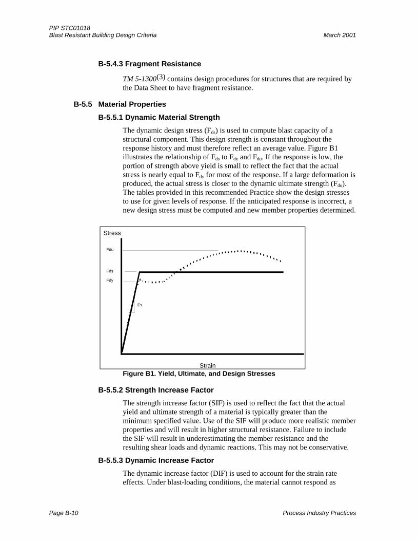
The dynamic design stress (Fds) is used to compute blast capacity of astructural component. This design strength is constant throughout theresponse history and must therefore reflect an average value. Figure B1illustrates the relationship of Fds to Fdy and Fdu. If the response is low, theportion of strength above yield is small to reflect the fact that the actualstress is nearly equal to Fdy for most of the response. If a large deformation isproduced, the actual stress is closer to the dynamic ultimate strength (Fdu).The tables provided in this recommended Practice show the design stressesto use for given levels of response. If the anticipated response is incorrect, anew design stress must be computed and new member properties determined.
Fdu
Fdy
Stress
Strain
Es
Fds
Figure B1. Yield, Ultimate, and Design Stresses
B-5.5.2 Strength Increase Factor
The strength increase factor (SIF) is used to reflect the fact that the actualyield and ultimate strength of a material is typically greater than theminimum specified value. Use of the SIF will produce more realistic memberproperties and will result in higher structural resistance. Failure to includethe SIF will result in underestimating the member resistance and theresulting shear loads and dynamic reactions. This may not be conservative.
B-5.5.3 Dynamic Increase Factor
The dynamic increase factor (DIF) is used to account for the strain rateeffects. Under blast-loading conditions, the material cannot respond as
PIP STC01018March 2001 Blast Resistant Building Design Criteria
Process Industry Practices B-11
quickly as the load is applied and an apparent strength increase is produced.Failure to include the DIF will also result in the under-prediction of memberend shears and reactions. The strain rate can vary depending on whether theblast load is a pressure wave or a shock wave. A pressure wave may notproduce strain rates sufficient to produce DIFs as high as shown in Table 2.
TM 5-1300(3) can be used for guidance on DIF values at relatively slowstrain rates.
B-6 Structural Design
B-6.1 Design Methods and Procedures
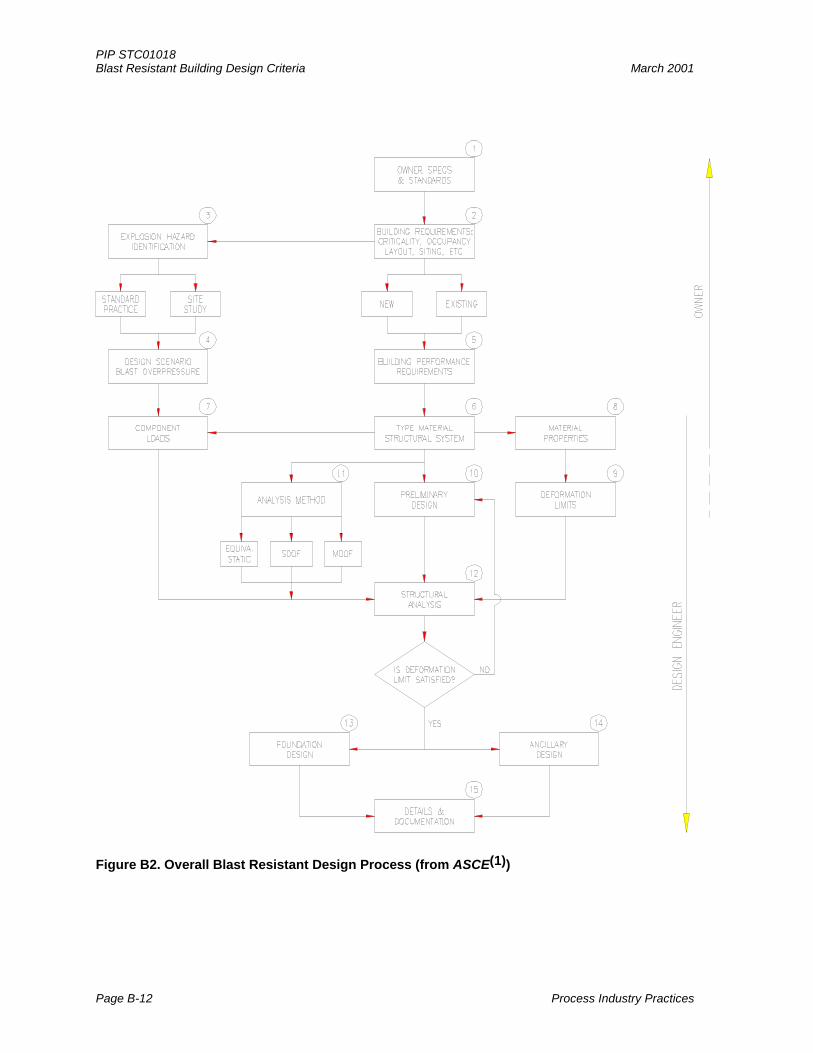
An overall process involved in design of blast resistant structures in petrochemical
facilities is shown in Figure B2 from ASCE(1). Most of the overlapping steps in thedesign process shown in Figure B2 will normally be the responsibility of theEngineer. If the Owner has specific requirements in these areas, they should bespelled out in the Data Sheet or the project/job design specifications. The Engineershould bring any unclear items to the attention of the Owner at the earliest possibletime to avoid project delay.
PIP STC01018Blast Resistant Building Design Criteria March 2001
Page B-12 Process Industry Practices
Figure B2. Overall Blast Resistant Design Process (from ASCE(1))
PIP STC01018March 2001 Blast Resistant Building Design Criteria
Process Industry Practices B-13
B-6.2 Load Combinations
Most design codes for conventional buildings have provisions for combination ofdesign loads such as live, wind, seismic, snow, etc. For blast design, a decision mustbe made about which of these loads to include simultaneously with blast loads. Deadloads are always included, but most other transient live loads are not, although rooflive loads (full or partial) are typically included.
The portion of live load to be applied in combination with blast load should bedetermined by the Engineer on the basis of the amount of load that could reasonablybe expected to occur at the same time as the blast load. This would include snowloads, roof live loads, and floor loads. The full floor live load would not normally beused because of the low probability of blast occurring during application of the fullfloor live load. It is not normal practice to combine blast loads with extremeenvironmental loads such as wind or earthquake. In rare situations, it may beappropriate to analyze structural response for the blast load following application ofseismic loads (for example, where an earthquake causes damage in a process unit,which leads to an explosion).
Most conventional design codes specify load factors to be applied to provide a factorof safety in the design. These load factors are typically set at 1.0 for blast designbecause a blast load is an extreme event.
B-6.3 Analysis Methods
B-6.3.1a SDOF - Approximate Solution (Equivalent Static Load)
This analysis method, which treats the required resistance as a static load, isbased on the single degree of freedom (SDOF) response to a simplified blastload and may be used for components loaded directly by the blast.
This approach has been quite popular in the past because it is simple toapply. It is used to approximate dynamic response without requiring
numerical integration of the equations of motion. ASCE(1) and ASCE
Manual 42(6) provide an empirical equation for computing the requiredresistance or equivalent static load for a component. These documents, as
well as TM 5-1300,(3) also provide plots of the response of an elastic-plasticSDOF system to a triangular shock load pulse. These represent approximatesolutions for an elastic-perfectly-plastic SDOF system subjected to a linearlydecaying blast load without a rise time.
Use of the equivalent static load method requires iteration. Initial propertiesfor the member must be selected to define the period of vibration. When thestatic equivalent load is computed and applied, a new section is selected onthe basis of computed resistance. This new section will have differentproperties than originally assumed, which will change the equivalent staticload. If a new equivalent static load is not computed, subsequent calculationsfor member end shear and connection design will not be correct. Thismethod does not directly calculate the dynamic shears and reactions of themember. The equivalent static load is used to determine these parameters,and in some cases may underestimate these items and thus the connection
PIP STC01018Blast Resistant Building Design Criteria March 2001
Page B-14 Process Industry Practices
requirements. Another drawback of this method is that it cannot model theinteraction of connected components.
The equivalent static load method should be used only for analysis of alinearly decaying blast load without a negative phase. Furthermore, it shouldnot be used for non-ideal resistance functions nor used to model differencesin resistance for the positive response phase and the rebound phase.
B-6.3.1b SDOF - Numerical Integration
This is the most commonly used method for blast resistant design. Thismethod allows most structural components to be modeled as a single, spring-mass system, which greatly simplifies the analysis of the time-historyresponse. This method can be used to model non-linear resistance functionsand the differences in resistance in the positive and rebound phases. It canalso be used to model complex pressure-time histories including negativepressure effects. The time-varying end reactions can be computed using theSDOF method. These reactions can then be applied to supporting membersto model component interaction. Special consideration needs to be given toselection of the appropriate mass to be applied to supporting members, basedon the relative time to maximum response of the member being supported.
Additional guidance is given in ASCE(1) and in References 11 and 12 formodeling and analyzing the response of structural components as SDOFsystems.
Pressure-impulse (P-I) curves, denoting lines of constant damagecorresponding to a particular response limit, may be used to evaluate theresponse of a structural component to a number of blast loads. This approach
is described in ASCE(1) and in other References (7, 8, and 10).
B-6.3.2 MDOF
The multi-degree of freedom (MDOF) analysis method can be used todetermine the dynamic response of interconnected members. Eachcomponent is modeled as a one-degree-of-freedom spring mass system.Several SDOF systems are combined numerically to produce a MDOFmodel. This method models mass and dynamic reaction effects on supportedmembers. A typical system for a wall design might be modeled as a three-degrees-of-freedom system consisting of a wall panel, girt, and framecolumn. This type of analysis may result in a much lower maximumdeflection than would a SDOF analysis if the periods of vibration of theconnected members are fairly close.
The MDOF method can be used to model non-rigid (spring) supports, whichmay reduce the required resistance of certain components. A spreadsheet canbe used to perform numerical integration of simple models consisting of twoor three degrees of freedom. Beyond this, a computer program is moreappropriate. There are a limited number of special purpose computerprograms suitable for this type of analysis although most of these programshave been developed for defense-related applications. It is also possible touse a commercially available general purpose finite element program,
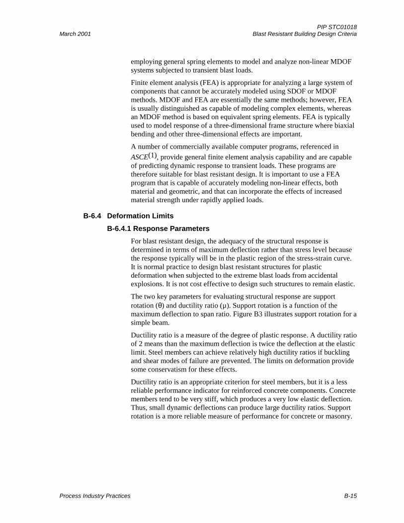
PIP STC01018March 2001 Blast Resistant Building Design Criteria
Process Industry Practices B-15
employing general spring elements to model and analyze non-linear MDOFsystems subjected to transient blast loads.
Finite element analysis (FEA) is appropriate for analyzing a large system ofcomponents that cannot be accurately modeled using SDOF or MDOFmethods. MDOF and FEA are essentially the same methods; however, FEAis usually distinguished as capable of modeling complex elements, whereasan MDOF method is based on equivalent spring elements. FEA is typicallyused to model response of a three-dimensional frame structure where biaxialbending and other three-dimensional effects are important.
A number of commercially available computer programs, referenced in
ASCE(1), provide general finite element analysis capability and are capableof predicting dynamic response to transient loads. These programs aretherefore suitable for blast resistant design. It is important to use a FEAprogram that is capable of accurately modeling non-linear effects, bothmaterial and geometric, and that can incorporate the effects of increasedmaterial strength under rapidly applied loads.
B-6.4 Deformation Limits
B-6.4.1 Response Parameters
For blast resistant design, the adequacy of the structural response isdetermined in terms of maximum deflection rather than stress level becausethe response typically will be in the plastic region of the stress-strain curve.It is normal practice to design blast resistant structures for plasticdeformation when subjected to the extreme blast loads from accidentalexplosions. It is not cost effective to design such structures to remain elastic.
The two key parameters for evaluating structural response are supportrotation (θ) and ductility ratio (µ). Support rotation is a function of themaximum deflection to span ratio. Figure B3 illustrates support rotation for asimple beam.
Ductility ratio is a measure of the degree of plastic response. A ductility ratioof 2 means than the maximum deflection is twice the deflection at the elasticlimit. Steel members can achieve relatively high ductility ratios if bucklingand shear modes of failure are prevented. The limits on deformation providesome conservatism for these effects.
Ductility ratio is an appropriate criterion for steel members, but it is a lessreliable performance indicator for reinforced concrete components. Concretemembers tend to be very stiff, which produces a very low elastic deflection.Thus, small dynamic deflections can produce large ductility ratios. Supportrotation is a more reliable measure of performance for concrete or masonry.
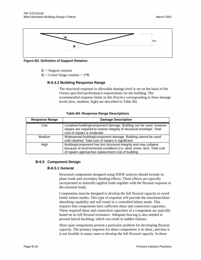
PIP STC01018Blast Resistant Building Design Criteria March 2001
Page B-16 Process Industry Practices
θθθθ1
θθθθ2
Xm
Figure B3. Definition of Support Rotation
θ1 = Support rotationθ2 = Center hinge rotation = 2*θ1
B-6.4.2 Building Response Range
The structural response or allowable damage level is set on the basis of theOwner-specified performance requirements for the building. Therecommended response limits in this Practice corresponding to three damagelevels (low, medium, high) are described in Table B4.
Table B4. Response Range Descriptions
Response Range Damage Description
Low Localized building/component damage. Building can be used; howeverrepairs are required to restore integrity of structural envelope. Totalcost of repairs is moderate.
Medium Widespread building/component damage. Building cannot be useduntil repaired. Total cost of repairs is significant.
High Building/component has lost structural integrity and may collapsebecause of environmental conditions (i.e. wind, snow, rain). Total costof repairs approaches replacement cost of building.
B-6.5 Component Design
B-6.5.1 General
Structural components designed using SDOF analysis should include in-plane loads and secondary bending effects. These effects are typicallyincorporated as statically applied loads together with the flexural response tothe transient loads.
Components must be designed to develop the full flexural capacity to avoidbrittle failure modes. This type of response will provide the maximum blast-absorbing capability and will result in a controlled failure mode. Thisrequires that components have sufficient shear and connection capacities.These required shear and connection capacities of a component are typicallybased on its full flexural resistance. Adequate bracing is also needed toprevent lateral buckling, which can result in sudden failures.
Short span components present a particular problem for developing flexuralcapacity. The primary response for these components is in shear, and thus itis not feasible in many cases to develop the full flexural capacity. In these
PIP STC01018March 2001 Blast Resistant Building Design Criteria
Process Industry Practices B-17
cases, the maximum resistance produced by the transient load should bedetermined for the entire response history. End shears and reactions shouldbe based on 120% of the maximum attained resistance applied as a uniformload over the member.
B-6.5.2 Reinforced Concrete
Design of reinforced concrete should be to the ultimate strength methodaccording to ACI 318(13) or comparable concrete design methods. Thecustomary strength reduction factor (φ) is to be taken as 1.0, and a dynamicstress factor (SIF * DIF) is applied according to Section 5.5.3 of thisrecommended Practice. In addition, because of the importance of adequateshear capacity to develop ductile flexural behavior in reinforced concretecomponents, the minimum static compressive strength for blast resistantdesign is set at 4,000 psi (28 Mpa). The higher strengths assure a morereliable performance in shear. However, a value less than 3,000 psi (21 Mpa)should not be used. A compressive strength of 5,000 psi (35 Mpa) isconsidered acceptable for concrete design. However, compressive strengthsabove this value have not yet had adequate testing to assure proper dynamicperformance under blast load conditions.
Reinforcing steel higher than Grade 60 (420 Mpa) should not be used. Inaddition, bar sizes above a #10 (32 mm) should not be used because ofdecreased ductility for large bars. Use of a greater number of smaller bars ispreferred to decrease development length requirements.
Time phasing of the interaction equation may be used; however, because ofinaccuracies in load-time phasing and response, it is important to apply someconservatism to the design.
Prestressed concrete members should not be used. Prestressing strands havevery limited ductility and may result in catastrophic collapse underapplication of blast loads at ultimate strength. In addition, prestressedcomponents are typically designed for load application in one direction anddo not provide adequate rebound resistance.
B-6.5.3 Structural Steel
The load and resistance factor design methods of AISC(14) or comparablelimit state methods may be used for the blast resistant design of structuralsteel. As in reinforced concrete design, φ = 1.0 and the dynamic strengthincrease factors should be used. However, it is advisable to use/specify50 ksi (345 Mpa) yield material because of the variation in material strengthfor A36 steel. Use of A36 material, which has an actual yield strengthsignificantly more than 36 ksi, can lead to unconservative prediction ofreaction forces and required shear resistance.
B-6.5.4 Cold-Formed Steel
The load and resistance factor design (LRFD) method of AISI(15) or acomparable strength limit state method may be used for the blast resistantdesign of cold-formed steel members. A φ = 0.9 factor is applied to plasticmoment capacity when computing an ultimate resistance to reflect the
PIP STC01018Blast Resistant Building Design Criteria March 2001
Page B-18 Process Industry Practices
potential buckling of a section before developing the full plastic moment. Inaddition, the dynamic strength increase factors in Section 5.5.2 of thisPractice should be applied.
B-6.5.5 Open Web Steel Joists (OWSJ)
OWSJ are not well suited for blast design because of difficulties indeveloping ultimate moment capacity. Web buckling can occur, especially atmember ends, resulting in premature failure. Instability of the bottom chordduring rebound can significantly reduce the rebound capacity. This potentialproblem can be remedied by supplying additional bracing to the bottomchord. When used, OWSJ should be designed on the basis of applicablestandard specifications by the Steel Joist Institute(16). Joist manufacturers’allowable load capacity tables may be used in determining the ultimatecapacity of OWBJ under blast loading by multiplying the listed stress-basedvalues by the applicable safety factor and by the appropriate dynamicstrength increase factors.
Quality control in the manufacture of OWSJ can be an issue. Welding of barjoists does not typically comply with AWS D1.1(17) and may not be capable ofdeveloping the plastic moment capacity of the joist. Because of thesepotential deficiencies in blast resistant designs, bar joists should be usedwith caution.
B-6.5.6 Reinforced Masonry
Only fully inspected reinforced masonry (concrete or brick) is appropriatefor blast resistant design. The ACI(18) and UBC(19) specifications on theultimate strength reinforced masonry should be used for blast resistantdesign, particularly those requirements pertaining to seismic design.
ASCE(1)and TM 5-1300(3) also provide guidance specific to the design ofreinforced masonry for blast resistance.
Masonry construction responds similarly to singly reinforced concrete. Fullygrouted cells normally provide adequate compression and shear capacity todevelop flexural strength. Horizontal truss or ladder type reinforcingprovides minimal flexural capacity and is not generally classified asreinforced masonry.
Connections at floor and roof are typically weak links in conventionalreinforced masonry construction. The connections must be capable ofresisting inward and rebound loads. Connections for load-bearingconstruction are especially critical. Walls should be doweled into floor androof slabs.
B-6.6 Structural Framing
Analysis of frame sidesway should include analysis with and without blastoverpressure on the leeward side of the building. Normally, excluding this load willproduce the maximum response; however, in some situations the load applied to theleeward side may produce the maximum response when it occurs in phase with therebound response. Accurate computation of time of arrival for the blast wave isimportant for this part of the analysis.
PIP STC01018March 2001 Blast Resistant Building Design Criteria
Process Industry Practices B-19
Dynamic analysis of sliding and overturning effects requires judgment on allowabledeformations by the Engineer. Some guidance is provided in References 20 and 21.Vertical movement on the order of 1 inch (25 mm) is considered acceptable, whilelateral movement as much as 2 inches (50 mm) may be acceptable. Using staticmethods, it is normally possible to show an adequate resistance to overturning andsliding. However, multi-story structures and buildings with a large aspect ratio floorplan may require dynamic analysis to show acceptable response.
ASCE(1), as well as other references (3, 11, 12), provides guidance in modeling andcalculating the dynamic response of structural systems to blast loading.
B-6.7 Foundation Design
Analysis of explosion accident data has shown that foundation failure is rare. This isprimarily due to the inability of the supported structure to transfer the entire blastload to the foundation. Additionally, foundation members are typically massivecompared with superstructures and thus provide greater resistance to blast loads thandoes the supported building. Usually foundation components are simply designedstatically for the capacities of the structural components they support. However, ifthis proves to be too conservative or costly, a more accurate dynamic analysis of thestructure/foundation system can be performed as discussed above.
B-7 Ancillary Items
B-7.1 Blast Doors
The Owner should determine whether blast doors are required for the building. Blastdoors are expensive, even for low blast loads, and may not be cost effective at lowrisk levels. Conventional hollow metal doors will not be operational aboveapproximately 0.5 psi (3.4 kPa) applied peak pressure. If blast pressure entering astructure is not sufficient to cause damage, a conventional door may be acceptable.
Door hardware may not be required to remain operational if additional protectedexits are provided. This situation may exist for doors on a wall receiving reflectedloads. It may be appropriate to allow these doors to be substantially damaged if asufficient number of doors are located in building faces receiving side-on blast loads.The Owner should select an allowable response category for design as shown inAppendix A. Additional information regarding door performance and design is
provided in ASCE(1).
Support for blast door frames is very important. Typically, subframes are providedby the building contractor during wall construction. This allows construction tocontinue while blast doors are being fabricated, which may take several weeks ormonths. Door framing should be provided by the manufacturer.
B-7.2 Windows
Windows should be avoided in buildings subjected to significant blast loads.Laminated glass and polycarbonate glazing can provide substantial blast resistance;however, they require a large rebate, or bite, to prevent the glazing from pushingthrough the frame.
PIP STC01018Blast Resistant Building Design Criteria March 2001
Page B-20 Process Industry Practices
Reputable suppliers of blast resistant windows have test data available tosubstantiate performance. If windows are designed by the vendor, supportingcalculations should be provided.
B-7.3 Openings
Small openings or low applied blast loads may not produce an appreciable increasein pressure in the building. In these situations, blast valves or other devices will notbe required. For structures near a process unit, leakage pressures through air intake
openings can be significant and valves or attenuators are required. TM 5-1300(3)
contains methods for predicting leakage pressure through openings.
Blast valves typically incorporate a moving disk that seals the opening and preventsentry of blast pressures. Blast attenuators significantly reduce leakage pressures butdo not completely eliminate the blast.
Passive blast valves have no moving parts and reduce blast pressures by creating atortuous exit path rather than a seal.
B-7.4 Penetrations
Premanufactured multi-cable transits (MCT) are available for use in blast resistantbuildings. These devices have a frame that is anchored into the concrete or masonry.Flexible collars are placed around pipes running through the MCT and are clampeddown to prevent leakage of the blast pressure into the structure. These MCTs areavailable in a variety of sizes.
B-7.5 Suspended Items
Light fixtures in suspended ceilings can produce a serious hazard to occupantsduring a blast. Ceiling grids, unless seismically rated, will not support fluorescentlight ballasts and ventilation dampers. These items can be anchored to the roofframing with heavy gauge wire or threaded rod. Any item weighing more than10 pounds (5 kg) should be independently anchored.
B-8 References
1. Design of Blast Resistant Buildings in Petrochemical Facilities, Task Committee on BlastResistant Design, American Society of Civil Engineers (ASCE), New York, NY, 1997.
2. Management of Hazards Associated with Location of Process Plant Buildings,Recommended Practice 752, American Petroleum Institute, Washington, D.C., 1996.
3. TM 5-1300, Structures to Resist the Effects of Accidental Explosions (two volumes),Departments of the Army, Navy, and Air Force, Washington, DC, 1990.
4. Siting and Construction of New Control Houses for Chemical Manufacturing Plants, SafetyGuide SG-22, Manufacturing Chemists Association, Washington, DC, 1978.
5. An Approach to the Categorization of Process Plant Hazard and Control Building Design,Issued by the Safety Committee of the Chemical Industry Safety and Health Council,Chemical Industries Association, 1992.
PIP STC01018March 2001 Blast Resistant Building Design Criteria
Process Industry Practices B-21
6. Design of Structures to Resist Nuclear Weapons Effects, Manual No. 42, Committee onDynamic Effects, American Society of Civil Engineers, New York, NY, 1985.
7. Explosion Hazards and Evaluation, W. E. Baker, Elsevier Scientific Publishing Company,New York, NY, 1983.
8. Guidelines for Evaluating Process Plant Buildings for External Explosions and Fires, Centerfor Chemical Process Safety of the American Institute of Chemical Engineers, New York,NY, 1996.
9. Guidelines for Evaluating the Characteristics of Vapor Cloud Explosions, Flash Fires andBLEVE’s, Center for Chemical Process Safety of the American Institute of ChemicalEngineers, New York, NY, 1994.
10. Method for the Determination of Possible Damage to People and Objects Resulting fromReleases of Hazardous Materials (CPR 16E), (Green Book), Committee for the Preventionof Disasters Due to Dangerous Substances, The Director-General of Labour, The Hague,1992.
11. Structural Dynamics: Theory and Computation, third edition, M. Paz, Van NostrandReinhold Inc., New York, NY, 1991.
12. Introduction to Structural Dynamics, J. M. Biggs, McGraw-Hill Book Company, New York,NY, 1964.
13. Building Code Requirements for Reinforced Concrete (ACI 318-99) and Commentary (ACI318R-99), ACI Committee 318, American Concrete Institute, Detroit, MI, 1999.
14. Load and Resistance Factor Design Specification for Structural Steel Buildings, AmericanInstitute of Steel Construction, Chicago, IL, 1993.
15. Specification for the Design of Cold-Formed Steel Structural Members, Load and ResistanceFactor Design, Cold-Formed Steel Design Manual, American Iron and Steel Institute, 1997.
16. Standard Specifications for Open Web Steel Joists, K, LH, and DLH Series, Steel JoistInstitute, 1995.
17. Structural Welding Code - Steel, ANSI/AWS D1.1-00, American Welding Society, 2000.
18. Building Code Requirements for Masonry Structures, ACI 530/ASCE 592/TMS 402-92,American Concrete Institute, 1999.
19. Uniform Building Code, International Conference of Building Officials, Whittier, CA, 1994.
20. Design of Structures to Resist the Effects of Atomic Weapons, Technical Manual5-856-1, Department of the Army, Washington, DC, January 1960.
21. Overturning and Sliding Analysis of Reinforced Concrete Protective Structures, TechnicalPublication 4921, U.S. Army Picatinny Arsenal, Dover, NJ, 1976.
Related Documents