PERFECTION CalTool P/N: 65245 Manual #90549 Perfect Performance Products, LLC Painless Performance Products Division 2501 Ludelle Street Fort Worth, TX 76105-1036 800-423-9696 phone – 817-244-4024 fax Web Site: www.painlessperformance.com E-Mail: [email protected]

Welcome message from author
This document is posted to help you gain knowledge. Please leave a comment to let me know what you think about it! Share it to your friends and learn new things together.
Transcript

PERFECTION CalTool
P/N: 65245
Manual #90549
Perfect Performance Products, LLC Painless Performance Products Division
2501 Ludelle Street Fort Worth, TX 76105-1036
800-423-9696 phone – 817-244-4024 fax Web Site: www.painlessperformance.com
E-Mail: [email protected]
2
If you have any questions concerning use of this software or having trouble in general, please feel free to call Painless Performance Products' tech line at 1-800-423-9696. Calls are answered from 8am to 5pm central time, Monday thru Friday, except holidays. We have provided as accurate instructions as possible, and are always concerned about improvements to be made. Any comments or suggestions concerning these instructions please send a fax to (817)244-4024 or e-mail is always welcome at [email protected]. We appreciate your business.
Perfect Performance Products, LLC shall in no event be liable in contract or tort (including negligence) for special, indirect, incidental, or consequential damages, such as but not limited to, loss of property damage, or any other damages, costs or expenses which might be claimed as the result of the use or failure of the goods sold hereby, except only the cost of repair or replacement.
P/N 90549
December 06, 2007 Revision #3 07/10
Copyright 2007 by Perfect Performance Products, LLC

3
Congratulations, on the purchase of the Perfect Engine Management fully tunable
fuel-injection system. This booklet is designed as a guide through the tuning process. Tuning an injection system can be tricky and at times very complex, but with patience and some general guidelines, a superb running engine can be accomplished.
This kit contains the following parts:
Instruction Manual #90549 USB Key Software CD w/Case
Gray communication cable NGK Wide Band Interface Cable
NOTICE: This kit is ONLY compatible with Windows XP. It will not work with Windows Vista or Windows 7. This kit does not include a USB to Serial adaptor. Keyspan® company (www.keyspan.com) makes a very easy to use unit P/N USA-19HS. This is the ONLY adaptor which is compatible with this kit. This adaptor must be purchased for this kit and is available from most electronics suppliers.

4
Installing the Software
1. Start by placing the Software CD into the CD/DVD drive on the desired computer and close the drive door. The software will automatically start an installation wizard and walk you through the installation process.
2. Follow each step in the wizard and finish the software installation process. At the end when it asks if you would like to start the software, remove the check from the box and close the window.
3. Now that the software has been installed onto your computer; there is an icon on your computer titled, “InGenius Perfect v2.2.
4. Now insert your purple USB key into a port on your computer.
5. Double click on the InGenius Perfect v2.2 icon on the desktop or go to START>All Programs>Painless Performance>Ingenius Perfect v2.2>Ingenius Perfect v2.2.
6. Now you can navigate through the software as explained in these instructions. Please read about each section and what changes it allows.
7. If you are ready to connect to your car with the Perfect System installed (it won’t work sitting on a workbench disconnected from your engine), place the CD that was included with your new KeySpan USB to Serial adaptor (P/N USA-19HS) and install the software as per the KeySpan software wizard.
8. Now connect the USB to Serial adaptor to the computer, connect the gray communication cable to the USB to Serial adaptor and then, with the ignition OFF plug the communication cable into the PERFECT engine harness.
9. After the software opens, turn the ignition to the ON position and watch for the red icon on the lower right hand corner of the screen to turn yellow and then green.
*If the icon did not change colors, the ECM and laptop are not communicating. Click the
Run button on the top of the screen one time, wait three seconds and then click it again. If the icon on the bottom of the screen still does not change, go to OPTIONS>Settings>Communication>and pick a different COM port. If it was set to COM 1 then try COM 3. Try each different Com Port until the icon on the bottom of the screen turns green. Each time a different Com Port is tried, the RUN button on the top of the screen will need to be toggled on and then off.
10. IMPORTANT/IMPORTANT/IMPORTANT: ALWAYS CLICK RECEIVE FOR THE
FIRST TIME WHEN THE SOFTWARE CONNECTS TO THE ECM. If you send a blank calibration to the ECM it will erase the ECM and it will be necessary to send it back to Painless to be recalibrated. THIS IS A VERY IMPORTANT DETAIL TO NOT MISS.

5
11. On part numbers 65140, 65141, 65252, and 65253 it is necessary to save the calibration onto your computer once you have received it. These calibrations are not in the software package where they can be retrieved once they are modified.
12. In order to load a calibration into the ECM, go to Calibration>Open>Calibrations> And then pick the appropriate calibration for your PERFECT SYSTEM. For example, A GM Tuned-Port Engine uses the L98 calibration.
13. Click on the desired calibration, open it and now click<SEND>. Do not turn off the ignition or try to start the vehicle until it’s completed downloading the cal to the ECM.
14. Now cycle the ignition off, wait seven seconds and then turn it to the On position.
15. Providing the engine, fuel system, and wiring installation is complete, turning the key to the start position should fire up the engine. Be sure to check the fuel pressure is at the specific pressures for your engine.

6
Section 1: General Tuning Guidelines
The adjustments available in this software have the potential to seriously damage the engine, if not done in the proper way. If a leaner than required mixture or too much spark timing is programmed into the engine ECM, detonation leading to a damaged engine will most likely occur. The calibrations provided for each engine are a good base to start programming from. Most of the time the spark tables for each engine combo will not need to be changed from the ones provided. When larger than stock camshafts are installed into an engine the idle and just off idle spark timing may need to be slightly advanced. The fuel tables and idle setup are most often in need of tuning. However, if the fuel/air mixture is too lean engine damage is imminent under sustained heavy loads. A rich condition will usually just produce clouds of black smoke from the exhaust pipe or even foul spark plugs.
Section 2: Dashboard
This screen serves as a “Scan Tool” for the PERFECT systems. The Dashboard shows live sensor data, (RPM, TPS, MAP, O2, and ECT), etc, when the engine is running or the key is in the ON position. This sensor data is used to analyze engine performance, sensor functionality and monitor critical sequences of events. For example, with the key on engine off, if the accelerator is not being pressed at all, the TPS gauge should read “0%”. Then with the accelerator pressed to the floor, the TPS gauge should read “99.6%”. The throttle adjustment is explained in more detail in Section 3: Idle.
The Dashboard can be customized by adding different gauges with each displaying different parameters and controlling how each parameter is displayed. Simply right click the mouse, choose “Design mode”, then right click the mouse again and select “New Gauge”. A window displaying all of the available features for each gauge will popup. Simply click on each tab and make decisions based on the appearance and function of the gauge desired. Many of the most important gauges come preset in this software package and can be modified at anytime. Once any design changes have been made, simply go to File-Save Workspace and save any changes that have been made.
Section 3: Fuel These screens contain the main Base Fuel Table with the fuel injector pulse width values. The values are in milliseconds of injector firing time or in other words, “How long the injector is open and allowing fuel to be sprayed into the engine”. Other adjustments in this section are simply a multiplier being applied to the values in the Base Fuel Table to increase or decrease the amount of fuel under specific conditions. It is critical the base fuel table values are as accurate as possible. See below for a description of how each adjustment is made in the Fuel screen:

7
1. Main – Base Fuel Table
RPM (Revolution per Minute) vs. MAP (Manifold Absolute Pressure) Sensor values in KPA (Kilopascals) These are the “X” and “Y” coordinates of the table.
How much fuel will the engine efficiently burn at a specific RPM? If the engine was held at a constant RPM and MAP(Load) listed on the Base Fuel Table, then the amount of fuel the injector will deliver is directly proportional to how many milliseconds the injector is command to be open.
It is crucial, when making adjustments to these values; the Coolant and Intake Air Temperature Compensation multipliers are set to 1.00 and the Transient Fuel multipliers must be set to 0. Only then will the engine be running solely on off the Base Fuel Table numbers. The O2 sensor selection in the Setup menu must be set to either “No Fuel Trim” or when present “Wideband Monitor”. This is to prevent any Closed Loop O2 fuel trim. This fuel injection system is only compatible with the NGK AFX wideband system. Call your local Painless Performance dealer for more details.
Painless has provided base calibrations for each engine supported, so be sure and start with the correct engine base calibration.
2. Compensation – Coolant Temperature and Intake Air Temperature
Coolant Temperature – These values are multiplied to the Base Fuel Table values to richen the mixture when the engine coolant, hence the engine, is cold. Or another way of looking at it is, it leans out the mixture as the engine warms up. Generally speaking, the values warmer than 176deg F should be 1.00. This would mean there is no enrichment due to the engine not being at running temperature.
Intake Air Temperature – These values are multiplied to the Base Fuel Table values to richen the mixture when the intake air is cool and to lean out the mixture when the intake air is hot. It’s best to use the Coolant Temperature to do most of the cold enrichment when the engine is cold and the Intake Air enrichment to fine tune fueling via air temperature.
3. Crank Fuel
Crank Fuel Prime – This is the initial shot of fuel from the injectors, comparable to throttling a cold carbureted engine before startup. The amount of fuel needed will vary with each different engine combination. Generally, more fuel is needed for quicker starts on engines with larger lift and duration camshafts. Watch for an overly large puff of black smoke out of the tailpipe during startup for an indication if the values in these fields are too large.
Crank Fuel – This is the amount of fuel sprayed into the engine from 0 rpm to 300 rpm. Colder temperatures require more fuel. Watch for an overly large puff of black smoke from the tailpipe for an indication of too much fuel during startup.
Crank to Base Fuel Compensation – These values are multiplied to the Base Fuel Table values and are used to gradually pull out the overly rich mixture during cranking. Once the engine speed is greater than 300 rpm, these values will start tapering off the amount of fuel being injected into the engine. Think of this as the transition to the Base Fuel Table while the engine is firing up. It’s equivalent to the choke pull-off on a carburetor.

8
Blend Time – This is the time it takes to transition from Crank Fuel to the Base Fuel Tables. Larger times here will slow down the transition and keep the fuel mixture rich longer. Smaller times here will speed up the transition and shorten the amount of time the mixture is richer. If the engine acts like it’s about to die after it first fires up, this value may need to be increased dependent upon if the Air/Fuel ratio measured in the exhaust goes lean and the engine stumbles.
4. Transient Fuel
MAP Acceleration Enrichment - These values are multiplied to the Base Fuel Table values to richen the mixture when there’s a change in the amount of engine vacuum. Engine vacuum can be directly translated into the amount of load being applied to an engine. With increased load, the engine will need more fuel to continue to do the same amount of work. Only with a change in the engine vacuum (load) will these fuel multipliers be applied to the mixture. Fuel Multiplier based on Delta Manifold Pressure (0 to 31.13 msec)
- “Delta” – means “change in”
TPS Acceleration Enrichment – These values are multiplied to the Base Fuel Table values to richen the mixture when there’s an increase in the amount of throttle being applied to the engine. Only on an increase in throttle will this adjustment be used by the ECM to richen the mixture. In carburetor terms, this adjustment would be the “accelerator pump”. If under a hard stomp of the throttle the engine stumbles, slightly increasing these values may help to fix the problem. Watching the Air/Fuel ratio in the exhaust with a wide band O2 sensor, see if the mixture goes too lean. Under a hard acceleration, it would be normal to possibly see the AFR goes as far rich as 10 to 1. Fuel Multiplier based on Delta Throttle Position (0 to 31.13 msec)
- “Delta” – means “change in”
5. Decel Fuel Cut-off
This enables or disables the fuel to be cut-off during a deceleration. It helps prevent and control back-firing when decelerating. It also prevents the engine from loading up with fuel during a high rpm throttle release. In most street applications, it is recommended to enable this feature for best drivability.
6. Oxygen Sensor
Idle Target A/F Ratio – This is the Air/Fuel Ratio the ECM will trim or add fuel to when in closed loop and the engine is idling. The ECM only has the authority for 20% more or less fuel. Before any closed loop fuel trim is used the Base Fuel table must be as accurate as possible.
Target A/F Ratio – This is the Air/Fuel Ratio the ECM will learn to for each engine load (MAP) and engine rpm. The desired Air/Fuel Ratio entered in each box is where the fuel trim adjustment in the software will adjust the Air/Fuel Ratio to be. Weather conditions and Barometric pressure have an effect on how much fuel will need to be added or subtracted from the base fuel table. Understand these values are a “Target” for the ECM to reach with Fuel Correction. This is displayed on the Main

9
Dashboard under the O2 Sensor gauges. Fuel Correction is the percentage of fuel being added or subtracted by the ECM from the Base Fuel Table. The less fuel being added or subtracted from the Base Fuel Table the closer the values are to being correct for a given calibration.
Enable RPM – This is the engine speed in which Closed Loop O2 Fuel control becomes active. Most stock, smooth idle engine combinations will want to enable the Closed Loop O2 control at around 600 rpm. Larger profile camshafts may require the enable rpm to be around 1500-2000 rpm.
Disable RPM – This is the engine speed in which the Closed Loop O2 Fuel control becomes inactive.
Coolant Temp Enable – This is the coolant temperature the engine must be up to in order to enter Closed Loop O2 control. It’s best to enter Closed Loop O2 control after the engine is at operating temperature. Generally about 10-15 degrees before the thermostat opening temperature will cover most engine combos.
Minimum Run Time – This is the minimum time the engine must be running before entering Closed Loop O2 control. The main purpose of this is for hot starts were the engine is still warmed up, but the O2 Sensor is not. If the O2 sensor is not warmed up it will not function properly and will most likely send the incorrect signal to the ECM.
Section 4: Spark The Base Spark Tables are developed in these screens. The sky’s the limit when configuring a spark table for ignition timing, so great care must be taken when modifying these tables. If too much spark advance is calibrated into the system, severe detonation will occur. Detonation will not only hinder engine performance, but can also severely damage the engine. Engine damage will result from too much spark advance and continual detonation.
The values in these tables are in degrees of spark advance before top dead center. In other words, “The number of degrees of crankshaft rotation the spark plug fires before each piston reaches Top Dead Center.” It is critical the Base Spark Table values are as accurate as possible. If the engine has detonation under a load or hard acceleration, be sure to retard the spark appropriately. Knock detection can be enabled or disabled in this section. Knock detection is useful in determining if the Base Spark Table has too much advance calibrated in it. Spark compensation based on coolant temperature and engine load can be adjusted here as well.
1. Main – Base Spark Table RPM (Revolution per Minute) vs. MAP (Manifold Absolute Pressure) Sensor values in
KPA (Kilopascals) These are the “X” and “Y” coordinates of the table. The MAP values are a direct translation to the amount of engine load. The higher
the MAP value reading indicates a larger engine load.
Base Spark Table values should only be calibrated when the engine is fully warmed up.
Painless has provided base calibrations for each engine platform supported, so be sure and start with the correct engine base calibration.

10
When the Knock System is enabled, a gauge showing the amount of Knock Retard on the Mini Dashboard can be used to determine if the Base Spark Table needs to be calibrated.
Generally speaking, the specific spark table provided for each engine platform supported will not need to be adjusted. Some examples of when the timing will need to be advanced more would be when a very large duration/lobe separation camshaft has been installed. The advance from idle and up to about 1500rpm would be the area to slightly increase, so a more stable idle speed can be achieved.
2. Compensation – Altitude and Coolant Temp and MAP
Altitude - This is used to add or subtract spark advance based on atmospheric pressure. The amount of atmospheric pressure is a measurement taken by the ECM every time the ignition is turned on. This directly relates to the amount of oxygen available to the engine to support combustion. Higher elevations have less atmospheric pressure; hence less air will be pushed into the engine with each piston stroke. SO, to maintain close to the same performance as in lower altitudes; advancing the timing slightly is one option.
It is always a good idea to monitor the knock system while tuning the spark tables. If the engine is knocking/has detonation/pinging and more spark timing is added, severe engine damage will eventually occur.
Coolant Temp and MAP – This table is designed to remove spark when both engine load and temperature are both at higher levels. As the engine is loaded and the engine speed decreases knock may occur. This is because the fuel sprayed into the cylinders is given a longer time to heat up before combustion. The amount of spark to be removed will depend on the engine combination, efficiency of the cooling system, and size/weight/gearing of the vehicle it is in. The base calibrations provided in this software package do not have values in this table.
Knock – All systems supported with this software from Painless Performance use the knock system. It is highly recommended to leave the knock system enabled to prevent severe engine damage. The maximum amount of spark retard the knock system is allowed to enable is 10 degrees.
Section 5: Idle
1. Idle Speed – Desired Idle Speed and Vehicle Speed Enable
Desired Idle Speed – This is where the idle speed of the engine is set based on coolant temperature. Higher idle speeds are recommended when the engine is cold to quicken the amount of time a cold engine takes to reach operating temperature. On the Dashboard there is an indicator called “Idle in Control of RPM” which tells if the ECM is in control of the idle speed. The throttle must be fully closed for this to occur.
Vehicle Speed Enable – Where applicable, this tells the ECM when to go into loop idle control in relation to MPH. A good place to start is 25mph.
11
2. Throttle Setup – Throttle Zero and Throttle Scaler
Throttle Zero – This is used to synchronize the throttle position sensor signal and what the ECM considers closed throttle. The calibration procedure for this is outlined on this screen. If this number is incorrect, Closed Loop Idle Air Control, Idle Spark Stabilizer and Stall Saver will not work properly.
Throttle Scaler – This multiplier is used to scale up or down the TPS reading to achieve the correct throttle position percentage at WOT(wide open throttle). With the throttle fully depressed, adjust this value until the percentage at WOT is 99.6%. On this system 99.6% is wide open throttle. Always be sure to check the Throttle Zero value by using the procedure in the software after adjusting the Throttle Scaler.
3. Advanced Idle Calibrations
Throttle Follower Intro – This value represents the number of steps per percentage of throttle opening the IAC (Idle Air Control) valve will open as the throttle is opened. This acts as a buffer when under a quick deceleration to help the transition from open throttle to closed throttle. Some carbureted applications had a dashpot to dampen a quick snap of the throttle. This adjustment does the same thing, only with the IAC. A value of 1 will cause the ECM to open the IAC one count per 1% of throttle position.
Vehicle Speed Follower Intro – This value represents the number of steps per vehicle speed (MPH) the IAC valve will open. This is especially useful on a long deceleration down a hill where the throttle is closed and the engine is still above the Desired Idle Speed. Without the Vehicle Speed Follower, the ECM will try to bring the idle down to the set Desired Idle Speed and fully close the IAC. Once the vehicle came to a stop, the engine speed would droop below the Desired Idle Speed and almost die because of the time it takes to open the IAC from its fully closed position.
Follower Decay – This is the rate in which the Throttle Follower is decayed out. How many seconds it takes to bring the IAC back to its Idle Speed Position. If the engines idle hangs or stays higher than normal, increase this value. If the engine idle droops and almost dies, decrease this value.
Stall Saver – This is a multiplier used to set a RPM below the Desire Idle Speed in which the Stall Saver goes into effect. So if the idle speed is 750 rpm and the value in this field is set at 0.7500, then the Stall Saver will enable at 562 rpm. Stall Saver adds IAC counts (opens) and advances the ignition timing to keep the engine from stalling.
Stall Steps – This is the number of IAC steps added by the ECM when in Stall Saver mode. This number will be added every .125 seconds or 8 times per second. The more steps added, the more aggressive the ECM will try to recover the engine from stalling.
Crank IAC Position – This is the IAC cranking position based on coolant temperature. When the ignition is turned to the on position the ECM will move the IAC to this position to give the engine the correct amount of air to start. The larger the number the higher the engine speed will flare when it first fires up. This is why it is not necessary to hold the throttle open while cranking a fuel injected engine, as it most likely would be on a carbureted engine.
IAC Max Position – This value is the upper limit for how many counts the IAC can open to. These values are setup at the factory and the Perfect System Calibrations

12
already have them. Under normal circumstances this value will not need to be changed.
IAC Max Base Position – This is the maximum IAC position without throttle follower, stall saver or load anticipation added. These values are setup at the factory and the Perfect System Calibrations already have them. Under normal circumstances this value will not need to be changed.
Section 6: Setup
1. Sensors – IAT Sensor IAT Sensor – This is where the Intake Air Temperature Sensor input to the computer
is enabled or disabled. If an IAT Sensor is present, enable this input. Calibration of the fuel via air temperature must be entered under the Fuel Screen. The IAT sensor calibration is useful to remove a slight amount of fuel as the air temperature increases or to add a slight amount of fuel as the air temperature decreases. On a really cold day, 32deg F and below, this adjustment can be used to enrich the fuel slightly.
2. Oxygen Sensor – Enable/Disable ● No Fuel Trim - This is exactly what is says, “No Fuel Trim” meaning the engine will
run directly off of the Base Fuel Table values only. This means the O2 system has been completely disabled. When using an external wide band O2 sensor to monitor the exhaust air/fuel ratio, this will need to be selected.
Stock Closed Loop – This is only used with a stock narrow band O2 sensor. All PERFECT systems use this type of sensor when no wide band O2 sensor is present.
These next two choices REQUIRE the use of a NGK AFX wide band Oxygen Sensor Kit P/N 91101.
NOTE: Included in this kit is a wideband interface harness with the purpose of connecting a NGK Wideband Sensor P/N 91101 into the main engine harness. Simply match and connect the wires based on their colors and plug into the O2 connector on the engine harness. Be sure and follow the instructions on the Wideband display module to do a free-air calibration before inserting the NGK O2 Sensor into the exhaust pipe.
Wideband Monitor – This is only used with the NGK AFX wide band kit. Its purpose is to accurately measure the oxygen content in the exhaust to indicate if the engine is receiving too much fuel or not enough fuel. More oxygen is lean and less oxygen is rich. The gauge on the Dashboard of the software that displays, “O2 Sensor” will indicate what the air/fuel ratio is in the exhaust. This gauge will not give an accurate measurement when a narrow band O2 sensor is being used.
Wideband Closed Loop – This is to enable closed loop O2 fuel trim after the base fuel table has been thoroughly calibrated. The ECM will compare the Air/Fuel ratio value in the Target Air/Fuel ratio table to the actual value read in the exhaust. The ECM has the authority to change the amount of fuel plus or minus 20% of the

13
values in the Base Fuel table. This is why it is best to have the Base Fuel Table’s values within at least 20% of the desired Air/Fuel ratio.
3. Fuel Pump – Prime Time at Keyup Prime Time at Keyup – This is the amount of time the fuel pump will run when the
ignition switch is initially turned to the on position. Its how the computer primes the fuel rail with pressurized fuel before the engine is being cranked to lessen the amount of time for fuel to be delivered and the engine to start. Three seconds is usually more than enough time to prime the system.
3. Rev Limit
Engine Speed Limit based on Coolant Temperature – This is the Rev Limiter on the Perfect System. Cold engines and overheating engines need to have a lower rev limit, than engines at normal operating temperature.
4. Aux Output – NOT SUPPORTED IN PERFECT APPLICATIONS 5. Fan 1 – On Temperature/Off Temperature
On Temperature – On all PERFECT systems this is the temperature in which the ECM will provide a ground signal to an electric cooling fan relay. Set this temperature at approximately 20 degrees Fahrenheit lower than the normal engine operating temperature.
Off Temperature – On all PERFECT systems this is the temperature in which the ECM will take away a ground signal to an electric cooling fan relay thus turning the fan off. Set this temperature at approximately 10 degrees Fahrenheit lower than the On Temperature set point in order for the fan to run continuously. In most cases, the electric cooling fan will not need to cycle on and off, but if such operation is desired the On and Off temperature set points will need to be adjusted.
6. Fan 2 - NOT SUPPORTED IN PERFECT APPLICATIONS 7. Set Timing – Enable/Disable
By enabling the “Set Timing” mode, the ECM will force the spark advance to 10 degrees of base spark timing. At this point, adjust the distributor until the base timing tab is showing 10 degrees of advance. Lock down the distributor and then disable the Set Timing function. This function is used to synchronize the distributor advance to the ECM advance. In other words, the ECM and the Engine’s distributor are now calibrated to each other. This function is only used on adjustable distributor ignitions engines.
14
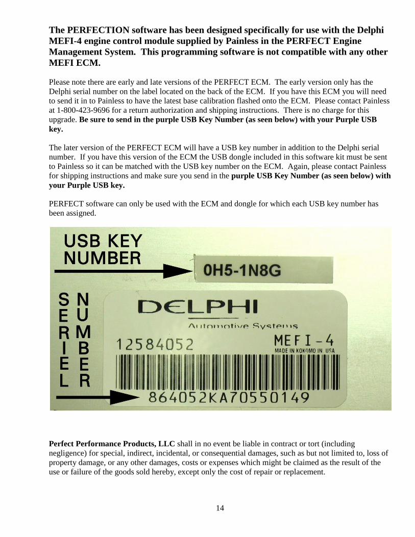
The PERFECTION software has been designed specifically for use with the Delphi
MEFI-4 engine control module supplied by Painless in the PERFECT Engine
Management System. This programming software is not compatible with any other
MEFI ECM.
Please note there are early and late versions of the PERFECT ECM. The early version only has the
Delphi serial number on the label located on the back of the ECM. If you have this ECM you will need
to send it in to Painless to have the latest base calibration flashed onto the ECM. Please contact Painless
at 1-800-423-9696 for a return authorization and shipping instructions. There is no charge for this
upgrade. Be sure to send in the purple USB Key Number (as seen below) with your Purple USB
key.
The later version of the PERFECT ECM will have a USB key number in addition to the Delphi serial
number. If you have this version of the ECM the USB dongle included in this software kit must be sent
to Painless so it can be matched with the USB key number on the ECM. Again, please contact Painless
for shipping instructions and make sure you send in the purple USB Key Number (as seen below) with
your Purple USB key.
PERFECT software can only be used with the ECM and dongle for which each USB key number has
been assigned.
Perfect Performance Products, LLC shall in no event be liable in contract or tort (including
negligence) for special, indirect, incidental, or consequential damages, such as but not limited to, loss of
property damage, or any other damages, costs or expenses which might be claimed as the result of the
use or failure of the goods sold hereby, except only the cost of repair or replacement.
Related Documents