PAX1/PAXL Linear Actuators User Manual

Welcome message from author
This document is posted to help you gain knowledge. Please leave a comment to let me know what you think about it! Share it to your friends and learn new things together.
Transcript

PAX1/PAXL Linear ActuatorsUser Manual
A4US
US
A4
US A4
US
A4
A4 US
US
A4
US
A4
A4 US
PAX1/PAXL Linear Actuators User Manual2
Section Page
Contents
1. Overview 2
2. General Information 3
3. Installation 4
4. Electrical Connections, DC Power 6
5. Electrical Connections, AC Power 8
6. User Interface 10
7. Commissioning 11
8. Installation Dimensions 13
9. Specifications 15
10. Maintenance 15
1. Overview
The PAX1/PAXL is a flexible linear actuator featuring a 25 mm maximum thrust rod stroke moving at speeds up to 60 mm/min and a maximum thrust of 2890 N all in a flameproof enclosure. The unit is inherently lock in last place as the thrust rod maintains its position upon loss of electrical power.
Power input options include 12-24 VDC or universal AC input 95-250 VAC 47-63 Hz.
The actuator can be actuated open loop using two optically isolated switch closure inputs (UP (EXTEND) and DN (RETRACT)) to move the actuators thrust rod. The actuator will continue to move the thrust rod in response to the inputs until either of the adjustable stroke limits are reached.
The actuator can be controlled with an isolated 4-20 mA analog input to proportionally position the thrust rod anywhere within its 25 mm stroke. In analog control mode, the unit is fail freeze if the control signal falls below 3.5 mA.
The actuator features UP and DOWN push buttons under the cover to facilitate commissioning and to permit local control of the actuator. There is an 8 mm (5/16”) female hex motor drive interface under the cover to allow manual actuator movement.
WARNING: The cover must not be removed in the presence of a hazardous classified combustible atmosphere when power is present. Multiple power sources are possible including those operating the analog inputs, pulse inputs, alarm relays and feedback circuits.
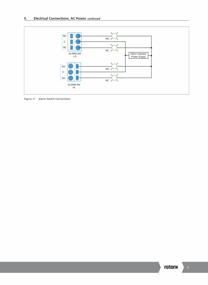
The actuator includes two fully adjustable 1 A, 250 VAC SPDT alarm relays (one High and one Low) providing alarm function when the actuator’s thrust rod reaches critical positions within its stroke. The relays are magnetically latched so the alarm switch states are maintained when the power is disconnected. This allows accurate alarm function on systems that remove power from the actuator between adjustments to conserve power as is typically done in solar powered installations.
The PAX1/PAXL offers an optional isolated 4-20 mA feedback output. This feedback feature is functional for both the pulse control and analog control configurations. The unit must be powered to facilitate the feedback output function.
The PAX1/PAXL can also be controlled via Modbus RTU digital communications over an optional optically isolated RS-485 network. The Modbus communications include a full featured command set allowing control, monitoring, commissioning and diagnostics capability over the digital communication.
A4US
US
A4
US A4
US
A4
A4 US
US
A4
US
A4
A4 US
3
2. General Information
The Linear Electric Actuator described in this document has been designed and manufactured with state of the art technology. All components are subject to stringent quality and environmental requirements during manufacture. Our quality systems are certified ISO 9001.
This user’s manual contains important information that enables a competent user to install, operate and maintain this linear electric actuator. The installation, operation and maintenance of this actuator in a hazardous area must be carried out by an appropriately trained and qualified person and in accordance with all relevant codes of practice for the particular Hazardous Area Classification.
WARNING
Installation must be carried out by qualified personnel in accordance with all national and local codes and ordinances.
Shock Hazard. Multiple power sources possible. Disconnect all power sources before servicing. Serious injury or death could result.
Read and understand all instructions carefully before starting installation. Save this document for future use. Failure to read and understand these instructions could result in improper operation of the device leading to equipment damage, serious injury, or death.
Hazardous Area Ratings
FM Explosion proofClass I, Division 1, Groups A,B,C,D, T6…T5Class II, III Division 1, Groups E,F,G, T6…T5Class 1, Zone 1, AEx db IIC, T6…T5 GbZone 21, AEx tb IIIC T85°C…100°C DbT6[T85°C]: Ta = -40°C to +65°CT5[T100°C]: Ta = -40°C to +70°CType 4X/6P, IP66/68
CSAClass I, Division 1, Groups B,C,D, T6…T5Class II, III Division 1, Groups E,F,G, T6…T5Ex db IIC, T6…T5 GbEx tb IIIC T85°C…T100°C DbT6[T85°C]: Ta = -40°C to +65°CT5[100°C]: Ta = -40°C to +70°CType 4X/6P, IP66, IP68
ATEX/IECEx/UKEXEx db IIC T6/T5 GbEx tb IIIC T85°C/T100°C Db
II 2 GDT6[T85°C]: Ta -40°C to +65°C, T5[T100°C] Ta -40°C to +70°CIP66, IP68
FM Hazardous Area Conditions of use
• Hazardous locations wiring must comply with ANSI/NFPA 70 (NEC®).
• Wiring must be rated 110 ºC or higher.
• Explosion proof certified seals are required within 18” for Groups A, B, C and D installations or within 2” for Group IIC installations.
• The PAX1/PAXL Actuator includes flame path joints. Consult Fairchild IPC if repairs of the flame path joints are necessary.
• Suitably rated conduit seals are required to prevent water ingress in NEMA 4X, IP66 applications or IP68 and NEMA 6P submersible applications. The seals must be rated for the environment of use such as hazardous area, ingress protection and temperature.
CSA Hazardous Area Conditions of use
• Hazardous locations wiring must comply with CSA: CEC Part 1.
• Explosion proof certified seals are required within 18” for both Zones and Division installations.
• The PAX1/PAXL Actuator includes flame path joints. Consult Fairchild IPC if repairs of the flame path joints are necessary.
• Suitably rated conduit seals are required to prevent water ingress in NEMA 4X, IP66 applications or IP68 and NEMA 6P submersible applications. The seals must be rated for the environment of use such as hazardous area, ingress protection and temperature.
• CAUTION: USE SUPPLY WIRES SUITABLE FOR AT LEAST 90 °C.
• ATTENTION: EMPLOYER DES FILS D’ALIMENTATION QUI CONVENNENT POUR AU MOINS 90 °C.
• WIRING TO BE CONNECTED TO A CLASS 2 CIRCUIT ONLY.
• RACCORDER UNIQUEMENT À UN CIRCUIT DE CLASSE 2”.
• CAUTION: KEEP COVER TIGHT WHILE CIRCUITS ARE ALIVE.
• ATTENTION: GARDER LE COUVERCLE BIEN FERMÉ TANT QUE LE CIRCUITS SONT SOUS TENSION.
• WARNING: POTENTIAL ELECTROSTATIC CHARGING HAZARD – SEE INSTRUCTIONS.
• AVERTISSEMENT: DANGER POTENTIEL DE CHARGE ELECTROSTATIQUE – VOIR LES INSTRUCTIONS.
• A SEAL SHALL BE INSTALLED WITHIN 18 in (45 cm) OF THE ENCLOSURE.
• UN SCELLEMENT DOIT ÊTRE INSTALLÉ À MOINS DE 45 cm (18 in) DU BOÎTER”.
A4US
US
A4
US A4
US
A4
A4 US
US
A4
US
A4
A4 US
4 PAX1/PAXL Linear Actuators User Manual
Hazardous Area (Classified) Conditions of use
• Under certain extreme circumstances, the non-metallic parts incorporated in the enclosure of this equipment may generate an ignition-capable level of electrostatic charge. Therefore the equipment shall not be installed in a location where the external conditions are conducive to the build-up of electrostatic charge on such surfaces. In addition, the equipment shall only be cleaned with a damp cloth.
• Contact the manufacturer if information of flameproof joints is needed.
3. Installation
The PAX1/PAXL can be mounted in any position without affecting its operation. It can be mounted to a flat surface using the mounting holes on the actuator. An optional mounting bracket is also available. For details, see “PAX1/PAXL Actuator Installation Dimensions”.
Installation below ground level
Conduit Seal: The PAX1/PAXL is rated for limited submerged operation but the user is responsible for ensuring water cannot enter the PAX1/PAXL enclosure through the conduit connection and conduit port. Ensure the conduit installation is water tight at elevations that may be submerged below water. Where conduit is prone to collect internal condensation, appropriate conduit traps, drains and seals must be employed to prevent condensation from collecting inside the PAX1/PAXL enclosure.
Wiring
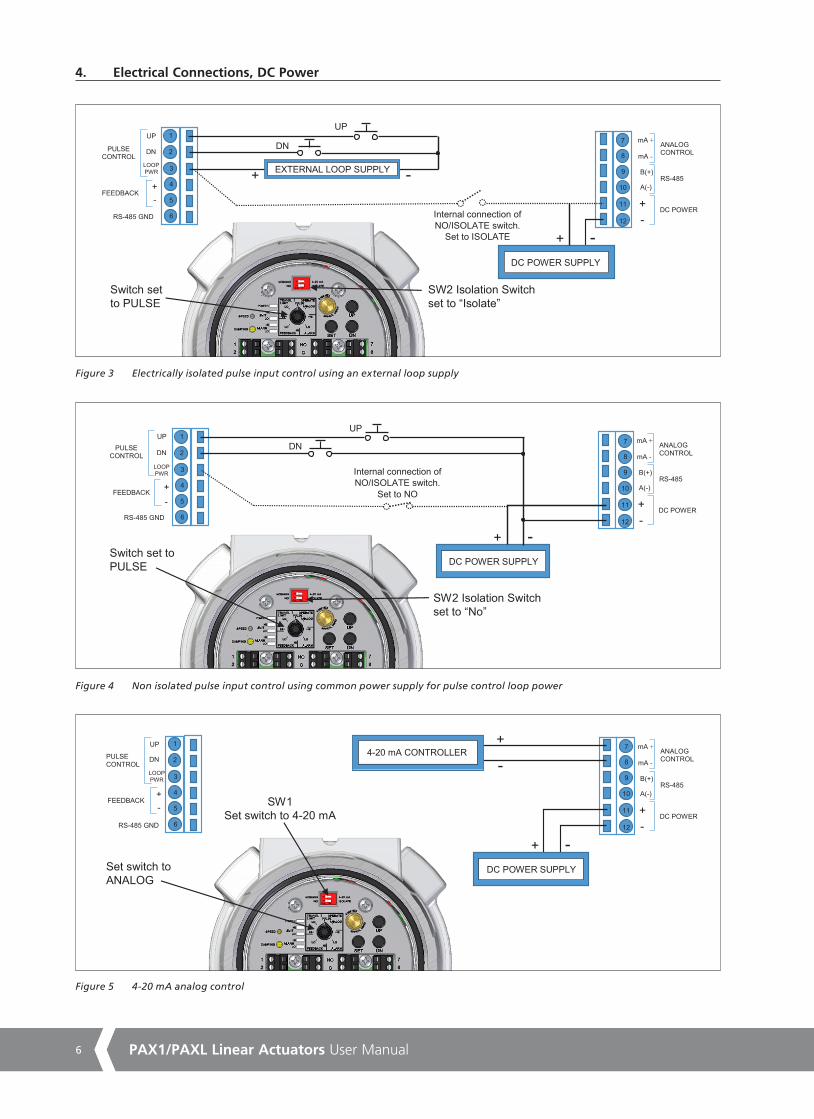
The PAX1/PAXL can be controlled with three different control interfaces (Analog, Pulse & Modbus). The wiring diagrams, Figures 3-8, below show the connections required to operate the unit based on the control type as well as connections to other features such as position feedback and alarm switches.
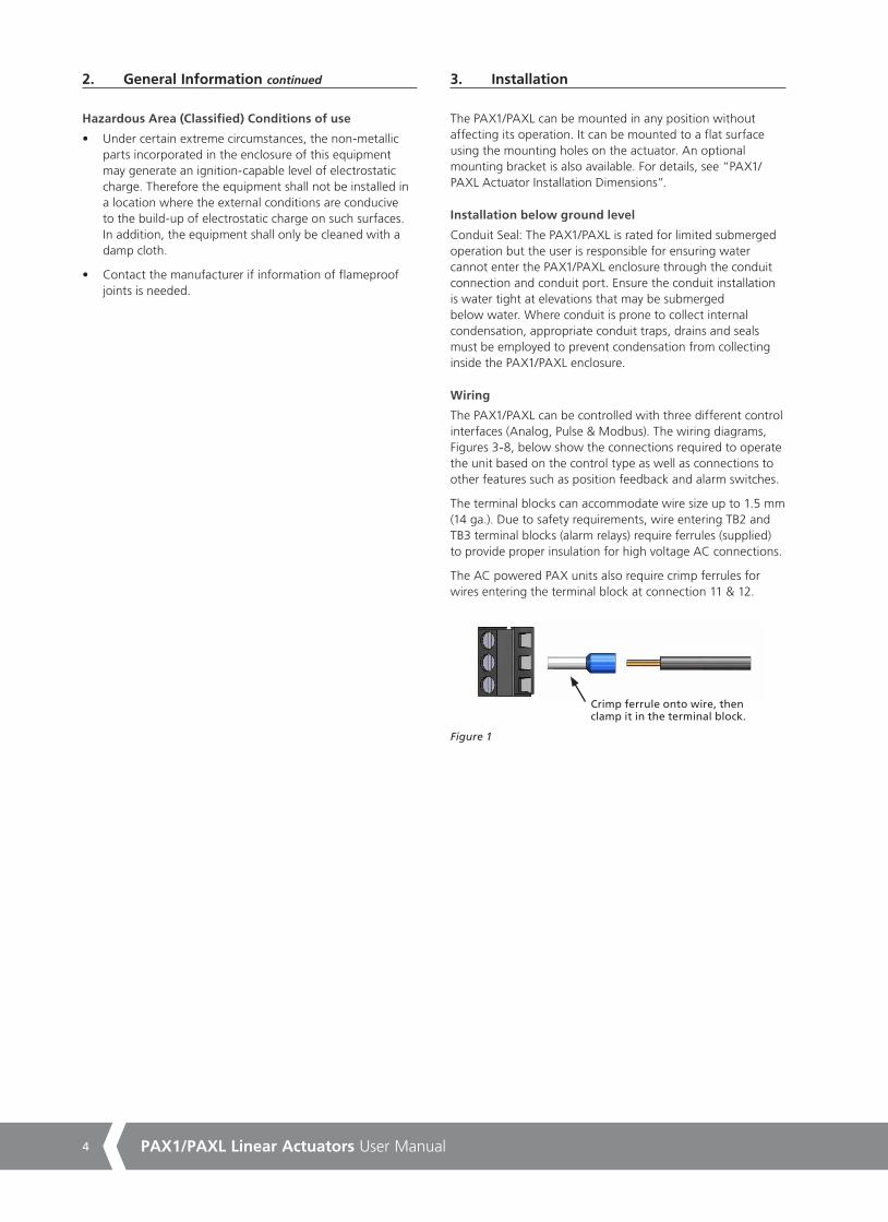
The terminal blocks can accommodate wire size up to 1.5 mm (14 ga.). Due to safety requirements, wire entering TB2 and TB3 terminal blocks (alarm relays) require ferrules (supplied) to provide proper insulation for high voltage AC connections.
The AC powered PAX units also require crimp ferrules for wires entering the terminal block at connection 11 & 12.
Crimp ferrule onto wire, then clamp it in the terminal block.
Figure 1
2. General Information continued
A4US
US
A4
US A4
US
A4
5
3. Installation continued
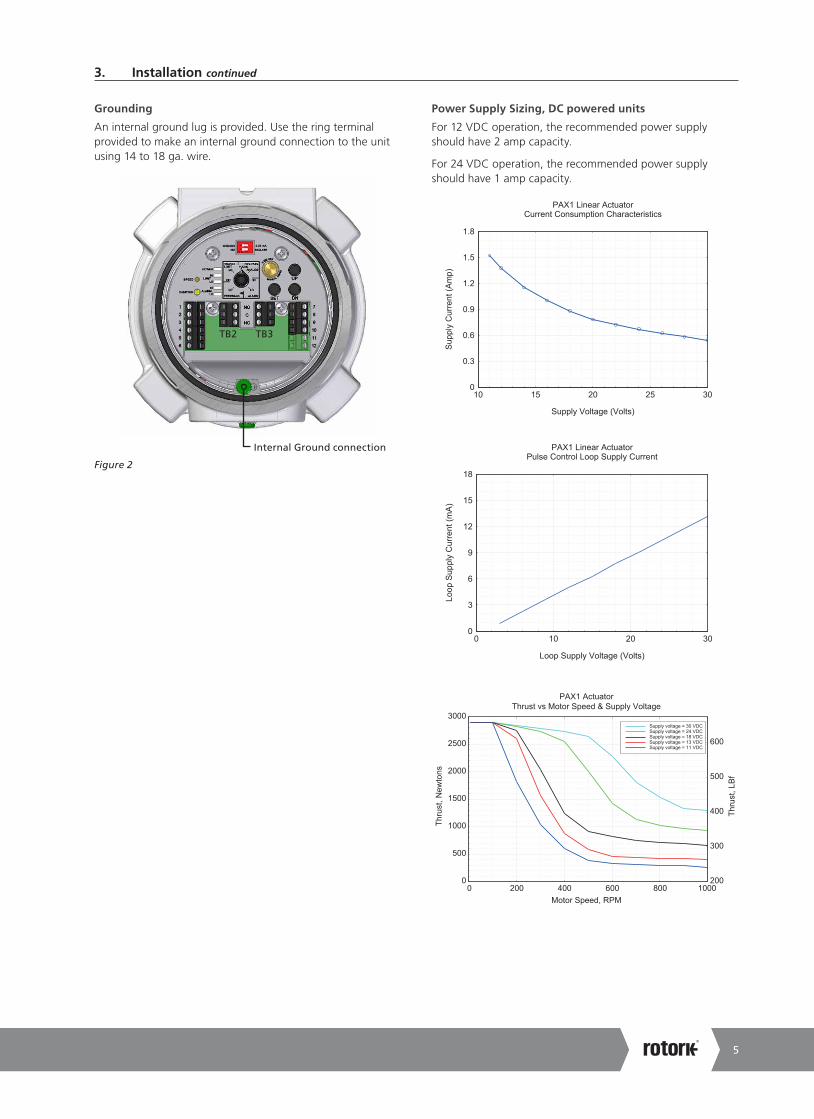
Grounding
An internal ground lug is provided. Use the ring terminal provided to make an internal ground connection to the unit using 14 to 18 ga. wire.
Internal Ground connection
TB2 TB3
Figure 2
Power Supply Sizing, DC powered units
For 12 VDC operation, the recommended power supply should have 2 amp capacity.
For 24 VDC operation, the recommended power supply should have 1 amp capacity.
0
0.3
0.6
0.9
1.2
1.5
1.8
10 15 20 25 30
Supply Voltage (Volts)
Supp
ly C
urre
nt (A
mp)
PAX1 Linear ActuatorCurrent Consumption Characteristics
0
3
6
9
12
15
18
0 10 20 30
Loop Supply Voltage (Volts)
Loop
Sup
ply
Cur
rent
(mA)
PAX1 Linear ActuatorPulse Control Loop Supply Current
0
3000
2500
2000
1500
1000
500
0 200 400 600 800 1000200
300
400
500
600
Supply voltage = 30 VDCSupply voltage = 24 VDCSupply voltage = 18 VDCSupply voltage = 13 VDCSupply voltage = 11 VDC
Motor Speed, RPM
PAX1 ActuatorThrust vs Motor Speed & Supply Voltage
Thru
st, L
Bf
Thru
st, N
ewto
ns
A4 US
US
A4
US
A4
A4 US
6 PAX1/PAXL Linear Actuators User Manual
4. Electrical Connections, DC Power
DN
1
2
3
4
5
6
7
8
9
10
11
12
UP
SW2 Isolation Switch set to “Isolate”
Switch setto PULSE
-+
Internal connection of NO/ISOLATE switch.
Set to ISOLATE
ANALOG CONTROL
mA +
B(+)
A(-)
+ -
mA -
DC POWER
RS-485 +
DN UP
- RS-485 GND
FEEDBACK
LOOP PWR
PULSE CONTROL
- +
DC POWER SUPPLY
EXTERNAL LOOP SUPPLY
Figure 3 Electrically isolated pulse input control using an external loop supply
+
DN
UP
- RS-485 GND
1
2
3
4
5
6
7
8
9
10
11
12
SW2 Isolation Switchset to “No”
FEEDBACK
Switch set toPULSE
Internal connection of NO/ISOLATE switch.
Set to NO
ANALOG CONTROL
mA +
B(+) A(-) + -
mA -
DC POWER
RS-485
DN UP
PULSE CONTROL
LOOP PWR
- +
DC POWER SUPPLY
Figure 4 Non isolated pulse input control using common power supply for pulse control loop power
1
2
3
4
5
6
7
8
9
10
11
12
4-20 mA CONTROLLER +
-
Set switch toANALOG
+
DN UP
- RS-485 GND
FEEDBACK
PULSE CONTROL
ANALOG CONTROL
mA +
B(+) A(-) + -
mA -
DC POWER
RS-485 LOOP PWR
- +
DC POWER SUPPLY
SW1Set switch to 4-20 mA
Figure 5 4-20 mA analog control
A4US
US
A4
US A4
US
A4
7
- +
1
2
3
4
5
6
7
8
9
10
11
12
DC POWER SUPPLY
+ -
RS-485 GND
FEEDBACK
PULSE CONTROL
ANALOG CONTROL
mA +
B(+) A(-) + -
mA -
DC POWER
RS-485
DN UP
LOOP PWR
MILLIAMMETER + -
-+ EXTERNAL LOOP SUPPLY
External loop supply forIsolated Feedback Loop
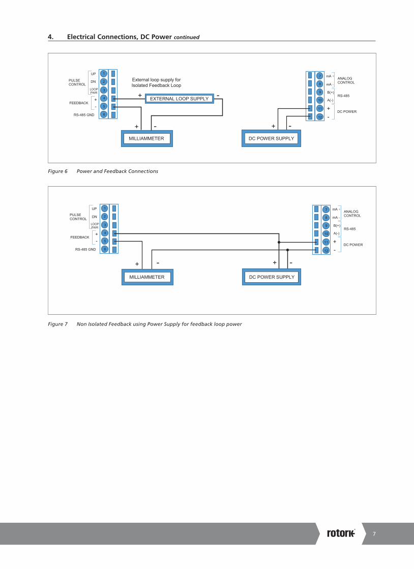
Figure 6 Power and Feedback Connections
1
2
3
4
5
6
7
8
9
10
11
12
+ -
+ -
+ -
RS-485 GND
FEEDBACK
PULSE CONTROL
ANALOG CONTROL
mA +
B(+) A(-) + -
mA -
DC POWER
RS-485
DN UP
LOOP PWR
DC POWER SUPPLY MILLIAMMETER
Figure 7 Non Isolated Feedback using Power Supply for feedback loop power
4. Electrical Connections, DC Power continued
A4 US
US
A4
US
A4
A4 US
8 PAX1/PAXL Linear Actuators User Manual
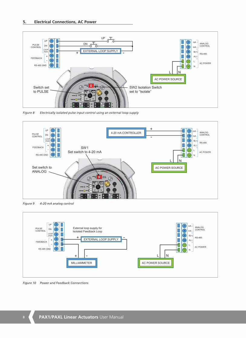
5. Electrical Connections, AC Power
DN
1
2
3
4
5
6
7
8
9
10
11
12
UP
SW2 Isolation Switch set to “Isolate”
Switch setto PULSE
-+
ANALOG CONTROL
mA +
B(+)
A(-)
L N
mA -
AC POWER
RS-485 +
DN UP
- RS-485 GND
FEEDBACK
LOOP PWR
PULSE CONTROL
L N
AC POWER SOURCE
EXTERNAL LOOP SUPPLY
Figure 8 Electrically isolated pulse input control using an external loop supply
1
2
3
4
5
6
7
8
9
10
11
12
4-20 mA CONTROLLER +
-
Set switch toANALOG
+
DN UP
- RS-485 GND
FEEDBACK
PULSE CONTROL
ANALOG CONTROL
mA +
B(+) A(-)
mA -
AC POWER
RS-485 LOOP PWR
SW1Set switch to 4-20 mA
L N
AC POWER SOURCE
L
N
Figure 9 4-20 mA analog control
1
2
3
4
5
6
7
8
9
10
11
12
AC POWER SOURCE
+ -
+ -
RS-485 GND
FEEDBACK
PULSE CONTROL
ANALOG CONTROL
mA +
B(+) A(-) L N
mA -
AC POWER
RS-485
DN UP
LOOP PWR
MILLIAMMETER
-+ EXTERNAL LOOP SUPPLY
External loop supply forIsolated Feedback Loop
L N
Figure 10 Power and Feedback Connections
A4US
US
A4
US A4
US
A4
9
5. Electrical Connections, AC Power continued
NO
NC C
ALARM SW LO
C NO
NC
NO
NO
NC
NC ALARM SW
HI
Alarm IndicatorPower Supply
Figure 11 Alarm Switch Connections
A4 US
US
A4
US
A4
A4 US
10 PAX1/PAXL Linear Actuators User Manual
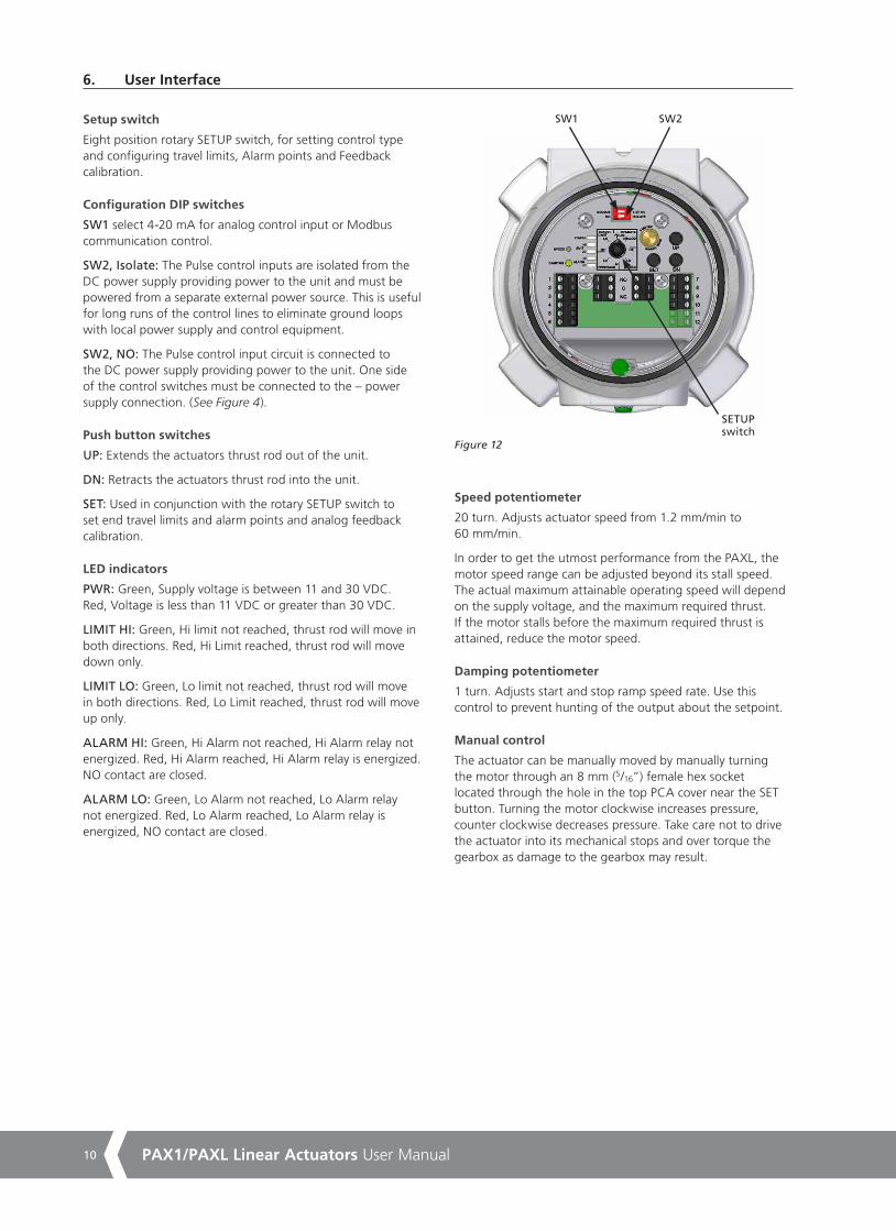
6. User Interface
Setup switch
Eight position rotary SETUP switch, for setting control type and configuring travel limits, Alarm points and Feedback calibration.
Configuration DIP switches
SW1 select 4-20 mA for analog control input or Modbus communication control.
SW2, Isolate: The Pulse control inputs are isolated from the DC power supply providing power to the unit and must be powered from a separate external power source. This is useful for long runs of the control lines to eliminate ground loops with local power supply and control equipment.
SW2, NO: The Pulse control input circuit is connected to the DC power supply providing power to the unit. One side of the control switches must be connected to the – power supply connection. (See Figure 4).
Push button switches
UP: Extends the actuators thrust rod out of the unit.
DN: Retracts the actuators thrust rod into the unit.
SET: Used in conjunction with the rotary SETUP switch to set end travel limits and alarm points and analog feedback calibration.
LED indicators
PWR: Green, Supply voltage is between 11 and 30 VDC. Red, Voltage is less than 11 VDC or greater than 30 VDC.
LIMIT HI: Green, Hi limit not reached, thrust rod will move in both directions. Red, Hi Limit reached, thrust rod will move down only.
LIMIT LO: Green, Lo limit not reached, thrust rod will move in both directions. Red, Lo Limit reached, thrust rod will move up only.
ALARM HI: Green, Hi Alarm not reached, Hi Alarm relay not energized. Red, Hi Alarm reached, Hi Alarm relay is energized. NO contact are closed.
ALARM LO: Green, Lo Alarm not reached, Lo Alarm relay not energized. Red, Lo Alarm reached, Lo Alarm relay is energized, NO contact are closed.
SW1 SW2
SETUPswitch
Figure 12
Speed potentiometer
20 turn. Adjusts actuator speed from 1.2 mm/min to 60 mm/min.
In order to get the utmost performance from the PAXL, the motor speed range can be adjusted beyond its stall speed. The actual maximum attainable operating speed will depend on the supply voltage, and the maximum required thrust. If the motor stalls before the maximum required thrust is attained, reduce the motor speed.
Damping potentiometer
1 turn. Adjusts start and stop ramp speed rate. Use this control to prevent hunting of the output about the setpoint.
Manual control
The actuator can be manually moved by manually turning the motor through an 8 mm (5/16”) female hex socket located through the hole in the top PCA cover near the SET button. Turning the motor clockwise increases pressure, counter clockwise decreases pressure. Take care not to drive the actuator into its mechanical stops and over torque the gearbox as damage to the gearbox may result.
A4US
US
A4
US A4
US
A4
11
7. Commissioning
WARNING
NOTE: multiple power sources possible. Do not remove cover in the field without first removing all power from the unit.
Commissioning must be done in a safe area before installing in a hazardous area.
Obtain special work permit before removing cover and making powered adjustments in the field.
1. Setting end travel limits
1.1 Disconnect Analog Input from 4-20 mA input terminals.
1.2 Turn on power to the unit.
1.3 Position the SETUP SWITCH to the TRAVEL LIMIT LO setting.
1.4 Using the UP (EXTEND) and DN (RETRACT) buttons under the cover, position the thrust rod to the desired most retracted position.
1.5 Press and hold the SET button and wait for the Limit Lo LED to turn from Green to Red and back to Green to set the low travel limit.
1.6 Position the SETUP SWITCH to the TRAVEL LIMIT HI setting.
1.7 Using the UP (EXTEND) and DN (RETRACT) buttons under the cover, position the thrust rod to the desired most extended position.
1.8 Press and hold the SET button and wait for the Limit Hi LED to turn from Green to Red and back to Green to set the high travel limit.
1.9 Position the SETUP switch to OPERATE/PULSE or OPERATE/ANALOG for normal operation.
1.10 When in OPERATE/PULSE mode, the actuator will respond to the UP (EXTEND) and DN (RETRACT) external pulse control inputs and will stop when the thrust rod reaches either end travel limit. The LIMIT LO and LIMIT HI LEDs will change from Green to Red when the limit is reached. The internal UP (EXTEND) and DN (RETRACT) push buttons will respond likewise.
1.11 When in TRAVEL LIMIT/LO or HI, mode, the Up (EXTEND) and DN (RETRACT) external pulse control inputs are disabled. The internal UP (EXTEND) and DN (RETRACT) push buttons will be active and will ignore the previous end of travel limits so that new limits may be set beyond the previously set limits. The LIMIT LO and LIMIT HI LEDs will continue to operate from the previously set limits until new limits are set.
2. Setting Analog Control Current
2.1 Connect a 4-20 mA signal source to the Analog Control input terminals. (See Figure 5.)
2.2 Turn on power to the unit.
2.3 Set SW1 to 4-20 mA.
2.4 Position the SETUP SWITCH to the TRAVEL LIMIT LO setting.
2.5 Using the UP (EXTEND) and DN (RETRACT) buttons under the cover, position the thrust rod to the desired most retracted position.
2.6 Apply the desired control current to the Analog Control input terminals for this thrust rod position.
2.7 Press and hold the SET button and wait for the Limit Lo LED to turn from Green to Red and back to Green to set the low travel limit and corresponding control current.
2.8 Position the SETUP SWITCH to the TRAVEL LIMIT HI setting.
2.9 Using the UP (EXTEND) and DN (RETRACT) buttons under the cover, position the thrust rod to the desired most extended position.
2.10 Apply the desired control current to the Analog Control input terminals for this thrust rod position.
2.11 Press and hold the SET button and wait for the Limit Hi LED to turn from Green to Red and back to Green to set the high travel limit and corresponding control current.
2.12 Position the SETUP switch to OPERATE/ANALOG to operate the actuator from the mA input terminals.
2.13 ERROR SIGNALS – If both the Hi Limit and Lo Limit LEDs blink red, then an error has occurred in setting the Analog Control signal. The most common error is setting the Lo or Hi Limit and forgetting to change the control current. In this case, the Lo Limit and Hi Limit are set with the same current. This signal also occurs if the difference in control current between the Lo Limit and Hi Limit is less than 4 mA. Correcting either the Lo Limit or Hi Limit setting or both will resolve the problem.
A4 US
US
A4
US
A4
A4 US
12 PAX1/PAXL Linear Actuators User Manual
3. Setting Alarm Switches (See Figure 8 for Alarm schematic)
3.1 Position the SETUP SWITCH to the ALARM SWITCH LO setting.
3.2 Using the UP (EXTEND) and DN (RETRACT) buttons, position the thrust rod to the desired LO ALARM position.
3.3 Press and hold the SET button and wait for the ALARM LO LED to turn from Green to Red and back to Green to set the ALARM SWITCH LO position.
3.4 Position the SETUP SWITCH to the ALARM SWITCH HI setting.
3.5 Using the UP (EXTEND) and DN (RETRACT) buttons, position the thrust rod to the desired HI ALARM position.
3.6 Press and hold the SET button and wait for the ALARM HI LED to turn from Green to Red and back to Green to set ALARM SWITCH HI position.
3.7 Position the SETUP SWITCH to the OPERATE PULSE or ANALOG mode for normal operation.
4. Setting Feedback Output (See Figures 6 & 7 for Output schematics)
4.1 Position the SETUP SWITCH to the OPERATE PULSE mode.
4.2 Using the internal DN (RETRACT) push button, adjust the actuator to its desired retracted limit position.
4.3 Position the SETUP SWITCH to FEEDBACK LO setting.
4.4 Using the UP (EXTEND) and DN (RETRACT) button, and monitoring the Analog Feedback current on the milliammeter, adjust the output current to the desired value (4 -12 mA) for this position.
4.5 Press the SET button and wait for the LIMIT LO & ALARM LO LED to simultaneously turn from Green to Red and back to Green to set the FEEDBACK LO output current.
4.6 Position the SETUP SWITCH to OPERATE / PULSE mode.
4.7 Using the internal UP (EXTEND) push button, adjust the actuator to its extended travel limit position.
4.8 Position the SETUP SWITCH to the FEEDBACK HI setting.
4.9 Using the UP (EXTEND) and DN (RETRACT) button, and monitoring the Analog Feedback current on the milliammeter, adjust the output current to the desired value (12 -20 mA) for this position.
4.10 Press the SET button and wait for the LIMIT HI & ALARM HI LED to simultaneously turn from Green to Red and back to Green to set the FEEDBACK HI output current.
4.11 Position the SETUP SWITCH to OPERATE / PULSE or OPERATE / ANALOG mode for normal operation.
5. Manual adjustment of thrust rod position
WARNING
Manual adjustment must only be done when power is removed from the unit.
NOTE: multiple power sources possible. Do not remove cover in the field without first removing all power from the unit.
5.1 The thrust rod of the actuator may be manually adjusted via an 8mm (5/16”) female hex interface located through the top of the unit with the cover removed.
5.2 Turn the adjustment clockwise to extend the thrust rod out of the unit and counter clockwise to retract the thrust rod into the unit.
5.3 Take care when manually adjusting the actuator as you can damage the unit if you force the thrust rod into its mechanical stops.
6. Restore Factory Defaults
The PAX1/PAXL actuator can be restored to its original factory settings using the following procedure.
6.1 Position the setup Switch to OPERATE/ANALOG.
6.2 Simultaneously press and hold the UP (EXTEND), DN (RETRACT), and SET buttons. For approximately 5 seconds, all of the LEDs will flash red on and off, and then they will stop flashing.
6.3 Release the buttons and the LEDs will begin flashing again to indicate “Restore Factory Defaults” mode is activated.
6.4 Press the SET button to restore the PAX1/PAXL to factory default settings. The LEDs will then return to their normal state.
6.5 The “Restore Factory Defaults” routine will cancel if (a) the UP (EXTEND) or DN (RETRACT) buttons are pressed or (b) the SET button is not pressed within 20 seconds.
6. Commissioning continued
A4US
US
A4
US A4
US
A4
13
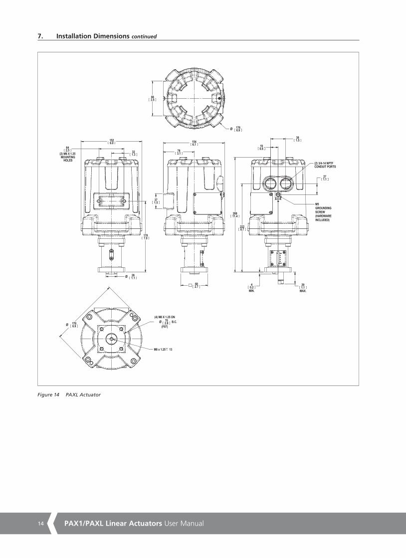
Figure 13 PAX1 Actuator
8. Installation Dimensions
23.00.91
213.68.41
103.54.07
(2) M8x1.25MOUNTINGHOLES
63.62.50
31.81.25
Ø 175.96.93
241.29.50
27.61.09 MIN
FULLY RETRACTED
53.02.09 MAX
FULLY EXTENDED
266.610.50
M5 GROUNDSCREW HOLE(HARDWAREINCLUDED)
27.11.07
38.11.50
147.15.79
3/4-14 NPTFCONDUIT PORTS (2)
19.10.75
78.03.07
152.46.00
A4 US
US
A4
US
A4
A4 US
14 PAX1/PAXL Linear Actuators User Manual
883.5
Ø 1766.9
28911.4
M5GROUNDING SCREW(HARDWARE INCLUDED)
291.1
MAX.
2228.7
381.5
190.8
271.1
(2) 3/4-14 NPTFCONDUIT PORTS
40.2
MIN.
642.5
(2) M8 X 1.25
1787.0
Ø 702.8 B.C.
(4) M8 X 1.25 ON
(F07)
1526.0
M8 x 1.25 13
281.1Ø
1766.9Ø
321.3
371.5
1546.1
682.7
783.1
MOUNTINGHOLES
7. Installation Dimensions continued
Figure 14 PAXL Actuator
A4US
US
A4
US A4
US
A4
15
9. Specifications
Electrical Supply (DC)
Power Supply Voltage 11-30 VDC
Power Consumption 22 W max, < 1.5 W standby
Electrical Supply (AC)
Power Supply Voltage 95-250 VAC, 47-63 Hz
Power Consumption 30 W max
Actuation Electrical, Analog
Actuation Control 4-20 mA, 1500 V optically isolated from power supply, Switch for common power supply
Actuation Supply 11-30 VDC (Loop Supply)
Min Current Span 4 mA; the difference in the control current setting between the Lo Limit, and Hi Limit
Actuation Electrical, Pulse
Actuation Control Switch Closure Sinking, (1) increase, (1) decrease
Actuation Current 10 mA sink, optically isolated 1500 V, Switch for common power supply
Actuation Supply 4 VDC minimum, 30 VDC maximum
Monitor
Alarm Switches Customer use, (2) SPDT each switch, 1 A 250 VAC, (Mag latching relay)
Position Feedback Optional, Isolated 4-20 mA, 11-30 VDC loop supply
Electrical Design Limits
Supply Voltage Limits (DC) 11 VDC min, 30 VDC max
Supply Voltage Limits (AC) 95 VAC min, 250 VAC max, 47-63 Hz
Analog Input Limits 3.5 mA min, 21 mA max, 100 mA w/o damage
Analog Output Limits 3.5 mA min, 21 mA max
External Loop Supply Limits 4 VDC min, 30 VDC max
Alarm Switches 1 A 250 VAC SPDT
Customer interface
Electrical Connections Screw terminal block under cover, 14-30 AWG
Actuator Speed Multi-turn pot, 1.2 – 60 mm/min*
Limit Adjustments Push button switch to accept current thrust rod position for (2) End of Travel limit, & (2) Alarm Switch, and Analog Feedback Calibration
Setup Switch 8 position rotary switch.
Damping Single-turn pot, 8:1 turn down
Isolation Switch Pulse Control Loop – Isolated/common to power supply
Actuator Performance
Maximum Stroke 25 mm
Maximum Force 2890 N (650 lbf) 1779 N (400 lbf over temperature -40 to +70 ºC)
Max Linear Speed 60 mm/min
Actuator Shaft M10 x 2 mm trapezoidal screw thd.
Power Up Analog Control: 2.1 sec.Initialization Time Pulse Control: 0.9 sec.
Feedback output: 0.9 sec.
EMC Ratings
FCC 47 CFR Part 15, Subpart B:2020
IC ICES-003:2016 Ed.6
CISPR 11:2009 Ed.5
IEC 61326-1:2012/07/10 Ed.2, Immunity - Equipment intended to be used in an industrial environment. Emissions per Section 7.2.
Environmental Ratings
Oper. Temp. Range -40 to +80 ºC, <50% Duty Cycle, <10 min cycle period (Motor Actuated)
-40 to +70ºC, Continuous Duty (Motor Actuated)
Ingress Protection IP66/68 See agency specific approvals on p.2
NEMA Type 4X/6P See agency specific approvals on p.2
*Actuation speed may need to be limited to achieve rated thrust at lower supply voltages.
CAUTIONShutting off actuator and disconnecting associated equipment can cause dangerous system conditions to exist. Ensure the System is properly prepared for maintenance to be performed on the actuator.
Periodic lubrication of Thrust Rod
After 20,000 operating cycles, re-lubricate the actuator thrust rod.
Make sure it is safe to disable the actuator in the system. Move the setup knob to the Operate Pulse mode and using
the UP (EXTEND) and DN (RETRACT) push buttons, position the thrust rod to a position that removes any thrust on the thrust rod. To expose the thrust rod remove the four bolts that attaches the actuator housing to the actuated device. Remove the Thrust Rod Cap exposing the Thrust Rod. With the setup knob to the Operate Pulse mode and pressing the UP (Extend) button, extend the thrust rod to its most extended opposition. Apply Dow Corning G-n lubricant to the exposed thrust rod thread. Using the DN (RETRACT) button, retract the thrust rod to its most retracted position. Re-install the thrust rod cap and the PAX1/PAXL actuator to the actuated device.
10. Maintenance
A4 US
US
A4
US
A4
A4 US

Rotork plcBrassmill Lane, Bath, UK
tel +44 (0)1225 733200email [email protected]
As part of a process of on-going product development, Rotork reserves the right to amend and change specifications without prior notice. Published data may be subject to change. For the very latest version release, visit our website at www.rotork.com
The name Rotork is a registered trademark. Rotork recognises all registered trademarks. Published and produced in the UK by Rotork. POWTG0621
PUB136-002-00Issue 04/21
www.rotork.com
A full listing of our worldwide sales and service network is available on our website.
Rotork Instruments North America 3920 West Point Blvd, Winston-Salem, NC 27103, USA
tel +1 (336) 659-3400email [email protected]
A4US
US
A4
US A4
US
A4
A4 US
US
A4
US
A4
A4 US
Related Documents