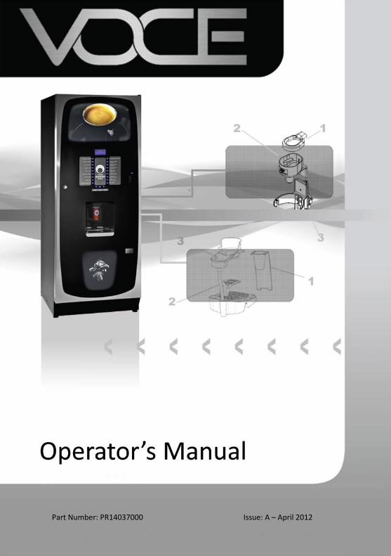
1 Part Number: PR14037000 Issue: A – April 2012

Welcome message from author
This document is posted to help you gain knowledge. Please leave a comment to let me know what you think about it! Share it to your friends and learn new things together.
Transcript
1
Part Number: PR14037000
Issue: A – April 2012
Congratulations on your purchase of the VOCE freestanding vending machine from Crane Merchandising Systems
Introduction / Important Safeguards
1
The following Symbol is used throughout this Operators Manual:
Safety First! Take care, risk of personal injury.
Crane Merchandising Systems accepts no responsibility for damage caused to the equipment through misinterpretation or misuse of the information contained in this manual.
© Copyright 2012 Crane Merchandising Systems
Introduction This manual provides you with guidance on the installation, daily operation and basic maintenance of your VOCE freestanding vending machine. Crane Merchandising Systems always recommend that a trained technician service its equipment.
Crane Merchandising Systems is committed to continuous product improvement. This means that the information within this document, although correct at time of publication, is for guidance only and may be subject to change without prior notice.
Important Safeguards Always follow these basic safety precautions when operating or maintaining your machine:
1. Ensure that you and anyone who will operate or maintain your machine have this manual available for quick and easy reference, and read all instructions carefully before commencing work.
2. Beware of Electricity. Certain maintenance operations require your machine to remain connected and switched on. Only trained personnel should carry out these routines, and independently of all other operations. Observation of safe working practices in accordance with current regulations is necessary at all times.
Important! Unless otherwise specified, always disconnect your machine from the electricity supply before commencing work.
3. Do not operate your machine if any part is damaged until a service technician has carried out necessary repairs and ensured that it is safe.
4. Allow your machine to cool before handling or moving.
5. Never immerse your machine in water, or any other liquid and never clean it with a water jet.
6. If your machine should freeze up, call a service technician to check it before switching on.
7. Ensure that you are familiar with the most recent Health and Safety at Work and Electricity at Work Regulations.
Important! This appliance is not intended for use by persons (including children and the infirm) with reduced physical, sensory or mental capabilities, or lack of experience and knowledge, unless they have been given supervision or instruction concerning use of the appliance by a person responsible for their safety. Children should be supervised to ensure that they do not play with the appliance
Your VOCE machine is for indoor use only and because it is a beverage machine, should be sited in a clean and hygienic area.
Section 1 – Machine Specifications
3
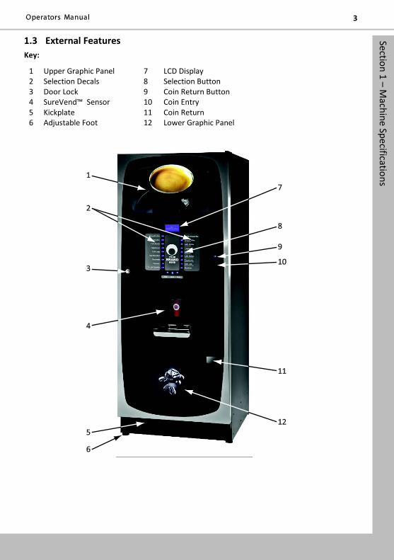
1.3 External Features Key:
1 Upper Graphic Panel 7 LCD Display 2 Selection Decals 8 Selection Button 3 Door Lock 9 Coin Return Button 4 SureVend™ Sensor 10 Coin Entry 5 Kickplate 11 Coin Return 6 Adjustable Foot 12 Lower Graphic Panel
Section 1 – Machine Specifications
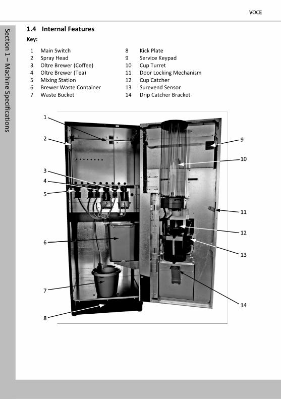
1.4 Internal Features Key:
1 Main Switch 8 Kick Plate 2 Spray Head 9 Service Keypad 3 Oltre Brewer (Coffee) 10 Cup Turret 4 Oltre Brewer (Tea) 11 Door Locking Mechanism 5 Mixing Station 12 Cup Catcher 6 Brewer Waste Container 13 Surevend Sensor 7 Waste Bucket 14 Drip Catcher Bracket
Section 2 – Installation (Engineers Procedure) 5
Section 2 - Installation (Engineer’s Procedure) Important! It is essential that the personnel responsible for installing and servicing your machine, understand the following:
1. The installation and commissioning of your machine should only be carried out by a trained and authorised service technician.
2. All water and electrical services must be correctly and safely connected.
3. All covers must be replaced correctly and securely and your machine left in a safe condition.
2.1 Siting your Machine 1. Your machine is for indoor use only. We recommend that it be situated in an area
with an ambient temperature not below 10º C and not exceeding 30º C. Your machine should be located near the appropriate water and electrical services as detailed below.
2. Prior to placing your machine in its final location, ensure that there is sufficient access space available via passageways, stairs, lifts, etc.
3. To ensure adequate ventilation, 100 - 150 mm (4 - 6 inches) clearance must be allowed between the back of the cabinet and the wall.
4. Open the door using the key provided. Remove transit packing and installation kit. Check for visual signs of damage which may have occurred during transit. If your machine is damaged or any parts are missing, you must contact the supplier immediately.
5. Level your machine in both the front-to-back and side-to-side planes by adjusting the feet. Ensure that the door opens and closes easily and the lock operates correctly.
2.2 Connecting the Water Supply
1. Your machine should be situated within 1 metre of a drinking water supply from a rising main, terminating with a W.R.C. approved 15mm compression stop-tap.
N.B. The water supply should comply with both the Statutory Instrument No.1147 - “Water, England and Wales” and The Water Supply (Water Quality) Regulations 1989. Water pressure at the stop-tap must be within the limits 2 - 6 Bar (200 Kpa - 600 Kpa).
2. Freshbrew & B2C Machines: If your VOCE machine is fitted with an Oltre brewer, or CoEx® B2C brewer, then it must be connected to the water supply via a water filter. This filter must be of food grade quality and able to remove temporary hardness (scale), heavy metals (lead, copper, iron, and cadmium), chlorine and any organic pollutants/discolouration.
Crane Merchandising Systems recommend and supply the Brita AquaQuell water filter.
Section 2 – Installation (Engineers Procedure)
Warning! If your Freshbrew or B2C machine is connected to a water supply and used without a water filter as specified above, your warranty will be void.
3. Connect the flexi-hose supplied with your machine to the stopcock ensuring that the seal is fitted correctly. Flush the water supply before connecting the machine.
N.B. When connecting your machine to a water supply always use a new flexi-hose (such as the one supplied). Never re-use an existing hose.
4. Connect the hose to the inlet valve located on the rear of your machine. Ensure that the seal is correctly fitted. Ensure that all water supply fittings are tight.
5. Turn on the water supply at the stop tap and check for leaks. Prime the water filter (where fitted) following the instructions supplied by the filter manufacturer.
2.3 Connecting the Electrical Supply Safety First!
The electrical safety of this appliance can only be guaranteed if it is correctly and efficiently earthed, in compliance with National and European regulations on electrical safety. Always ensure that the earthing is efficient. If you have any doubts, contact a qualified technician to check the system.
The manufacturer declines all liability for damage resulting from a system which has not been earthed. On no account should it be earthed only to the water supply pipe.
The appliance must be connected to mains protected by a certified safety switch (double pole) with a capacity appropriate for the application and in compliance with National and European regulations on electrical safety.
The appliance must be connected to a 230 Volt 50Hz 13 amp fused switched socket outlet, installed to the latest edition of the IEE regulations, using a 3 pin BS approved 13 amp fused plug for UK and in compliance with National and European regulations on electrical safety in other countries
Important: If the mains lead becomes damaged in any way it must be replaced by a special lead available from the manufacturer.
2.4 Commissioning Procedure A trained installation engineer must carry out the following procedure before your machine can be used for the first time. Ensure that the electrical and water services to the machine are connected correctly. Check for leaks in the water supply.
1. Open the front door of your machine.
2. Ensure that the waste bucket is fitted correctly. Clip the level detector and overflow pipes correctly onto the rim of the bucket.
3. Cup Turret. Remove the lid and fill the tubes with the correct size cups for the cup catcher type fitted to your machine. Allow the cups to drop into the tubes directly from the packaging. DO NOT touch the cups with your hands.
Section 2 – Installation (Engineers Procedure) 7
Important: Do not fill the tube directly above the cup dispense position. Allow the cup turret motor to rotate a full tube to the cup dispense position when the machine is powered up. Rotating the cup turret by hand will damage the mechanism.
Note: If you are loading paper cups, first inspect each pack for damage to the cup rims. Damaged cups must not be used.
4. Turn the machine on with the main switch on the back panel. The cup turret mechanism will index the first available cups to the dispense position and drop the cup stack into the cup drop mechanism. Fill the remaining empty cup stack with cups and replace the lid.
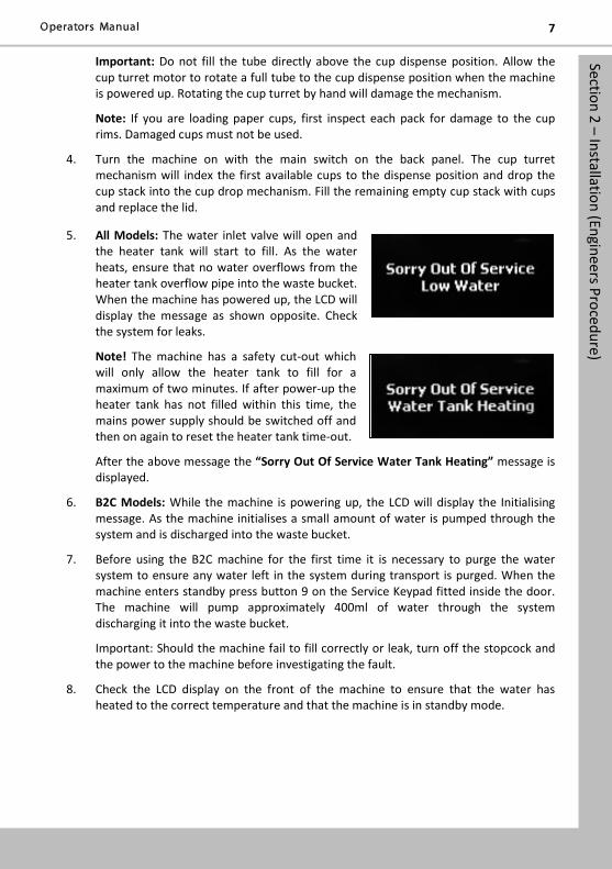
5. All Models: The water inlet valve will open and the heater tank will start to fill. As the water heats, ensure that no water overflows from the heater tank overflow pipe into the waste bucket. When the machine has powered up, the LCD will display the message as shown opposite. Check the system for leaks.
Note! The machine has a safety cut-out which will only allow the heater tank to fill for a maximum of two minutes. If after power-up the heater tank has not filled within this time, the mains power supply should be switched off and then on again to reset the heater tank time-out.
After the above message the “Sorry Out Of Service Water Tank Heating” message is displayed.
6. B2C Models: While the machine is powering up, the LCD will display the Initialising message. As the machine initialises a small amount of water is pumped through the system and is discharged into the waste bucket.
7. Before using the B2C machine for the first time it is necessary to purge the water system to ensure any water left in the system during transport is purged. When the machine enters standby press button 9 on the Service Keypad fitted inside the door. The machine will pump approximately 400ml of water through the system discharging it into the waste bucket.
Important: Should the machine fail to fill correctly or leak, turn off the stopcock and the power to the machine before investigating the fault.
8. Check the LCD display on the front of the machine to ensure that the water has heated to the correct temperature and that the machine is in standby mode.
Section 2 – Installation (Engineers Procedure)
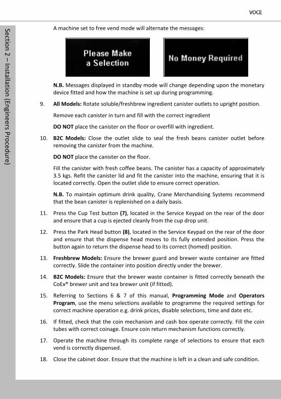
A machine set to free vend mode will alternate the messages:
N.B. Messages displayed in standby mode will change depending upon the monetary device fitted and how the machine is set up during programming.
9. All Models: Rotate soluble/freshbrew ingredient canister outlets to upright position.
Remove each canister in turn and fill with the correct ingredient
DO NOT place the canister on the floor or overfill with ingredient.
10. B2C Models: Close the outlet slide to seal the fresh beans canister outlet before removing the canister from the machine.
DO NOT place the canister on the floor.
Fill the canister with fresh coffee beans. The canister has a capacity of approximately 3.5 kgs. Refit the canister lid and fit the canister into the machine, ensuring that it is located correctly. Open the outlet slide to ensure correct operation.
N.B. To maintain optimum drink quality, Crane Merchandising Systems recommend that the bean canister is replenished on a daily basis.
11. Press the Cup Test button (7), located in the Service Keypad on the rear of the door and ensure that a cup is ejected cleanly from the cup drop unit.
12. Press the Park Head button (8), located in the Service Keypad on the rear of the door and ensure that the dispense head moves to its fully extended position. Press the button again to return the dispense head to its correct (homed) position.
13. Freshbrew Models: Ensure the brewer guard and brewer waste container are fitted correctly. Slide the container into position directly under the brewer.
14. B2C Models: Ensure that the brewer waste container is fitted correctly beneath the CoEx® brewer unit and tea brewer unit (if fitted).
15. Referring to Sections 6 & 7 of this manual, Programming Mode and Operators Program, use the menu selections available to programme the required settings for correct machine operation e.g. drink prices, disable selections, time and date etc.
16. If fitted, check that the coin mechanism and cash box operate correctly. Fill the coin tubes with correct coinage. Ensure coin return mechanism functions correctly.
17. Operate the machine through its complete range of selections to ensure that each vend is correctly dispensed.
18. Close the cabinet door. Ensure that the machine is left in a clean and safe condition.
Section 2 – Installation (Engineers Procedure) 9
2.5 Setting Up the Carbonator Unit (Where Fitted)
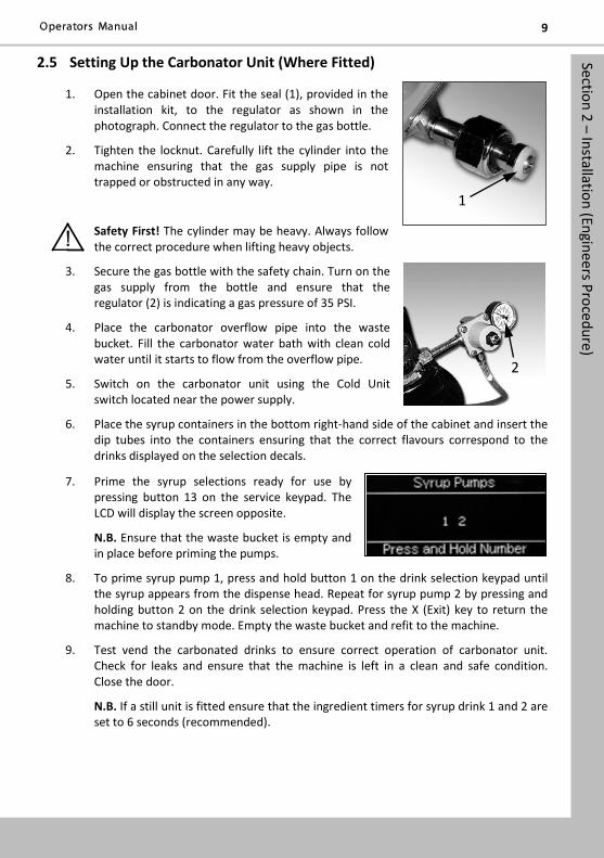
1. Open the cabinet door. Fit the seal (1), provided in the installation kit, to the regulator as shown in the photograph. Connect the regulator to the gas bottle.
2. Tighten the locknut. Carefully lift the cylinder into the machine ensuring that the gas supply pipe is not trapped or obstructed in any way.
Safety First! The cylinder may be heavy. Always follow the correct procedure when lifting heavy objects.
3. Secure the gas bottle with the safety chain. Turn on the gas supply from the bottle and ensure that the regulator (2) is indicating a gas pressure of 35 PSI.
4. Place the carbonator overflow pipe into the waste bucket. Fill the carbonator water bath with clean cold water until it starts to flow from the overflow pipe.
5. Switch on the carbonator unit using the Cold Unit switch located near the power supply.
6. Place the syrup containers in the bottom right-hand side of the cabinet and insert the dip tubes into the containers ensuring that the correct flavours correspond to the drinks displayed on the selection decals.
7. Prime the syrup selections ready for use by pressing button 13 on the service keypad. The LCD will display the screen opposite.
N.B. Ensure that the waste bucket is empty and in place before priming the pumps.
8. To prime syrup pump 1, press and hold button 1 on the drink selection keypad until the syrup appears from the dispense head. Repeat for syrup pump 2 by pressing and holding button 2 on the drink selection keypad. Press the X (Exit) key to return the machine to standby mode. Empty the waste bucket and refit to the machine.
9. Test vend the carbonated drinks to ensure correct operation of carbonator unit. Check for leaks and ensure that the machine is left in a clean and safe condition. Close the door.
N.B. If a still unit is fitted ensure that the ingredient timers for syrup drink 1 and 2 are set to 6 seconds (recommended).
1
2
Section 4 – Cleaning and Re-filling Procedure
Section 4 - Cleaning and Re-filling Procedures To maintain optimum drinks quality ensure that the machine is cleaned regularly following the schedule outlined below. Before carrying out the daily cleaning procedure described on the following pages, it is recommended that you have the following materials to hand
• Bactericidal Cleaner
• De-Staining Agent
• Cleaning Cloths
• Paper Towels
• Small Brush
• Two Large Buckets
• Disposable Gloves
• CoEx® Cleaning Tablets (B2C machines) – See note below
Cleaning Tablets - CoEx® Brewer (B2C Models) CMS recommends that the brewer cleaning tablets supplied with the machine are used exclusively for cleaning the CoEx® brewer fitted to VOCE B2C machines. These are available from your machine supplier in packs of 30 - part number ZC10598000. A detailed procedure for cleaning this brewer unit is outlined in sub-section 4.7 CoEx® B2C Brewer Unit.
4.5 Daily Cleaning & Filling Procedure Important: Cleaning and maintenance must be carried out daily. Use the procedure outlined on the following pages either at the end of the day or at the start of the day before the machine is in constant use.
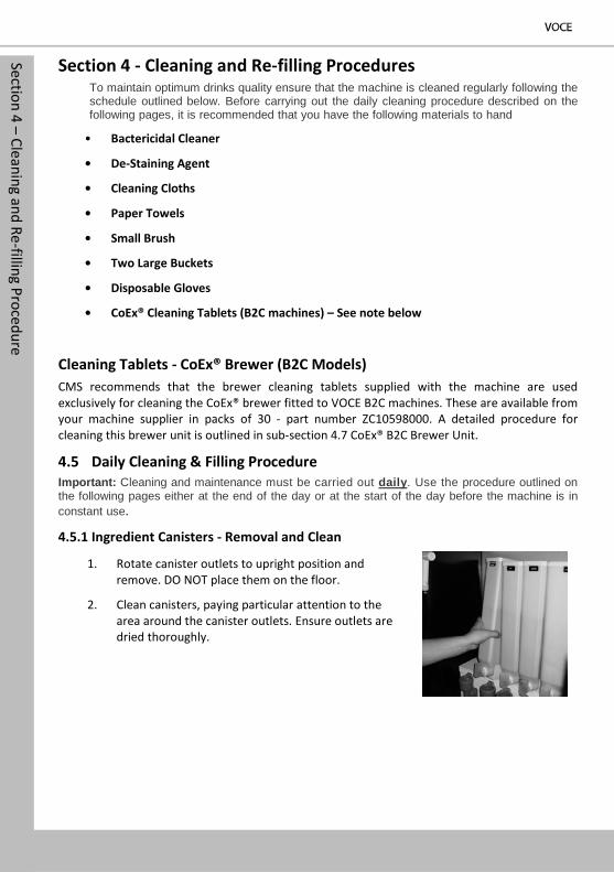
4.5.1 Ingredient Canisters - Removal and Clean
1. Rotate canister outlets to upright position and remove. DO NOT place them on the floor.
2. Clean canisters, paying particular attention to the area around the canister outlets. Ensure outlets are dried thoroughly.
Section 4 – Cleaning and Re-filling Procedure 11
4.5.2 Whipper System
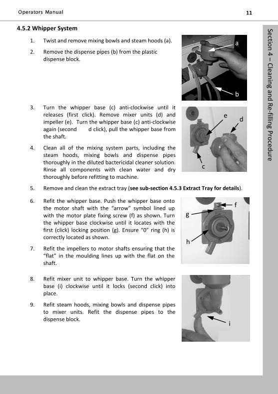
1. Twist and remove mixing bowls and steam hoods (a).
2. Remove the dispense pipes (b) from the plastic dispense block.
3. Turn the whipper base (c) anti-clockwise until it releases (first click). Remove mixer units (d) and impeller (e). Turn the whipper base (c) anti-clockwise again (second d click), pull the whipper base from the shaft.
4. Clean all of the mixing system parts, including the steam hoods, mixing bowls and dispense pipes thoroughly in the diluted bactericidal cleaner solution. Rinse all components with clean water and dry thoroughly before refitting to machine.
5. Remove and clean the extract tray (see sub-section 4.5.3 Extract Tray for details).
6. Refit the whipper base. Push the whipper base onto the motor shaft with the “arrow” symbol lined up with the motor plate fixing screw (f) as shown. Turn the whipper base clockwise until it locates with the first (click) locking position (g). Ensure “0” ring (h) is correctly located as shown.
7. Refit the impellers to motor shafts ensuring that the “flat” in the moulding lines up with the flat on the shaft.
8. Refit mixer unit to whipper base. Turn the whipper base (i) clockwise until it locks (second click) into place.
9. Refit steam hoods, mixing bowls and dispense pipes to mixer units. Refit the dispense pipes to the dispense block.
e d
c
g f
h
i
a
b
Section 4 – Cleaning and Re-filling Procedure
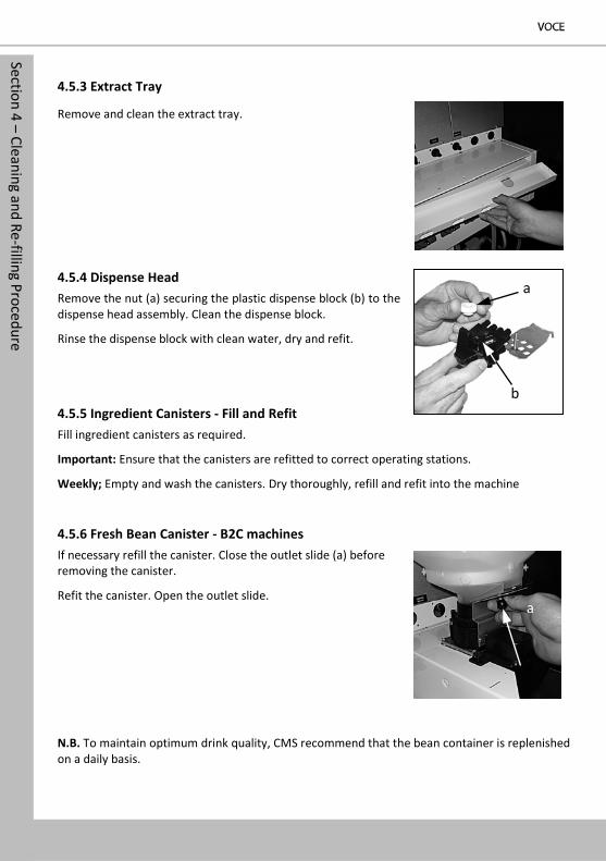
4.5.3 Extract Tray
Remove and clean the extract tray.
4.5.4 Dispense Head Remove the nut (a) securing the plastic dispense block (b) to the dispense head assembly. Clean the dispense block.
Rinse the dispense block with clean water, dry and refit.
4.5.5 Ingredient Canisters - Fill and Refit Fill ingredient canisters as required.
Important: Ensure that the canisters are refitted to correct operating stations.
Weekly; Empty and wash the canisters. Dry thoroughly, refill and refit into the machine
4.5.6 Fresh Bean Canister - B2C machines If necessary refill the canister. Close the outlet slide (a) before removing the canister.
Refit the canister. Open the outlet slide.
N.B. To maintain optimum drink quality, CMS recommend that the bean container is replenished on a daily basis.
a
b
a
Section 4 – Cleaning and Re-filling Procedure 13
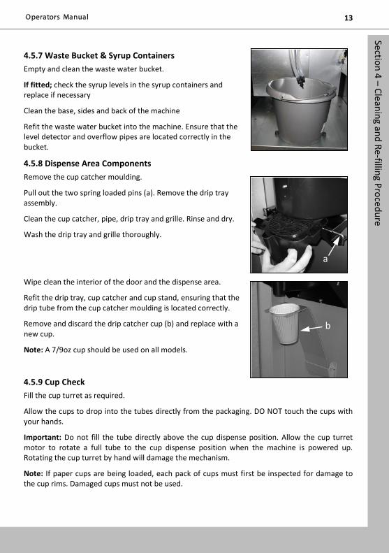
4.5.7 Waste Bucket & Syrup Containers Empty and clean the waste water bucket.
If fitted; check the syrup levels in the syrup containers and replace if necessary
Clean the base, sides and back of the machine
Refit the waste water bucket into the machine. Ensure that the level detector and overflow pipes are located correctly in the bucket.
4.5.8 Dispense Area Components Remove the cup catcher moulding.
Pull out the two spring loaded pins (a). Remove the drip tray assembly.
Clean the cup catcher, pipe, drip tray and grille. Rinse and dry.
Wash the drip tray and grille thoroughly.
Wipe clean the interior of the door and the dispense area.
Refit the drip tray, cup catcher and cup stand, ensuring that the drip tube from the cup catcher moulding is located correctly.
Remove and discard the drip catcher cup (b) and replace with a new cup.
Note: A 7/9oz cup should be used on all models.
4.5.9 Cup Check Fill the cup turret as required.
Allow the cups to drop into the tubes directly from the packaging. DO NOT touch the cups with your hands.
Important: Do not fill the tube directly above the cup dispense position. Allow the cup turret motor to rotate a full tube to the cup dispense position when the machine is powered up. Rotating the cup turret by hand will damage the mechanism.
Note: If paper cups are being loaded, each pack of cups must first be inspected for damage to the cup rims. Damaged cups must not be used.
a
b
Section 4 – Cleaning and Re-filling Procedure
4.5.10 Cash Box Empty contents from the cashbox, then refit turning the lock to secure.
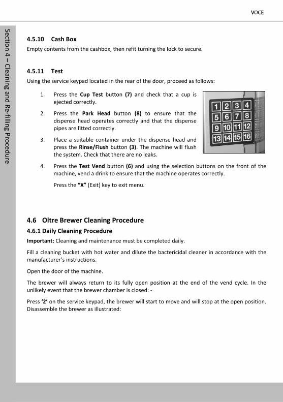
4.5.11 Test Using the service keypad located in the rear of the door, proceed as follows:
1. Press the Cup Test button (7) and check that a cup is ejected correctly.
2. Press the Park Head button (8) to ensure that the dispense head operates correctly and that the dispense pipes are fitted correctly.
3. Place a suitable container under the dispense head and press the Rinse/Flush button (3). The machine will flush the system. Check that there are no leaks.
4. Press the Test Vend button (6) and using the selection buttons on the front of the machine, vend a drink to ensure that the machine operates correctly.
Press the “X” (Exit) key to exit menu.
4.6 Oltre Brewer Cleaning Procedure 4.6.1 Daily Cleaning Procedure Important: Cleaning and maintenance must be completed daily.
Fill a cleaning bucket with hot water and dilute the bactericidal cleaner in accordance with the manufacturer’s instructions.
Open the door of the machine.
The brewer will always return to its fully open position at the end of the vend cycle. In the unlikely event that the brewer chamber is closed: -
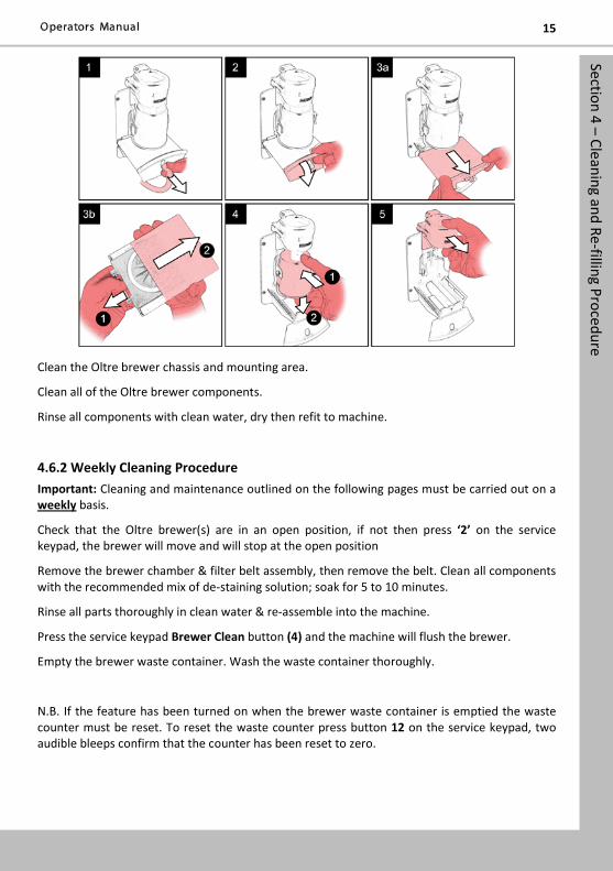
Press ‘2’ on the service keypad, the brewer will start to move and will stop at the open position. Disassemble the brewer as illustrated:
Section 4 – Cleaning and Re-filling Procedure 15
Clean the Oltre brewer chassis and mounting area.
Clean all of the Oltre brewer components.
Rinse all components with clean water, dry then refit to machine.
4.6.2 Weekly Cleaning Procedure Important: Cleaning and maintenance outlined on the following pages must be carried out on a weekly basis.
Check that the Oltre brewer(s) are in an open position, if not then press ‘2’ on the service keypad, the brewer will move and will stop at the open position
Remove the brewer chamber & filter belt assembly, then remove the belt. Clean all components with the recommended mix of de-staining solution; soak for 5 to 10 minutes.
Rinse all parts thoroughly in clean water & re-assemble into the machine.
Press the service keypad Brewer Clean button (4) and the machine will flush the brewer.
Empty the brewer waste container. Wash the waste container thoroughly.
N.B. If the feature has been turned on when the brewer waste container is emptied the waste counter must be reset. To reset the waste counter press button 12 on the service keypad, two audible bleeps confirm that the counter has been reset to zero.
Section 4 – Cleaning and Re-filling Procedure
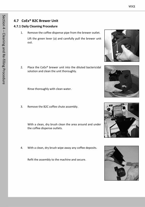
4.7 CoEx® B2C Brewer Unit 4.7.1 Daily Cleaning Procedure
1. Remove the coffee dispense pipe from the brewer outlet.
Lift the green lever (a) and carefully pull the brewer unit out.
2. Place the CoEx® brewer unit into the diluted bactericidal solution and clean the unit thoroughly.
Rinse thoroughly with clean water.
3. Remove the B2C coffee chute assembly.
With a clean, dry brush clean the area around and under the coffee dispense outlets.
4. With a clean, dry brush wipe away any coffee deposits.
Refit the assembly to the machine and secure.
a
Section 4 – Cleaning and Re-filling Procedure 17
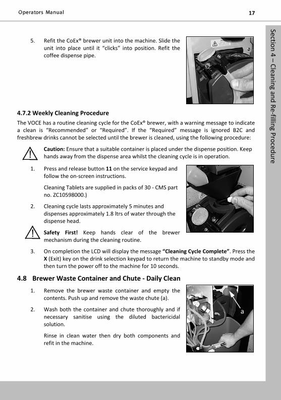
5. Refit the CoEx® brewer unit into the machine. Slide the unit into place until it “clicks” into position. Refit the coffee dispense pipe.
4.7.2 Weekly Cleaning Procedure The VOCE has a routine cleaning cycle for the CoEx® brewer, with a warning message to indicate a clean is “Recommended” or “Required”. If the “Required” message is ignored B2C and freshbrew drinks cannot be selected until the brewer is cleaned, using the following procedure:
Caution: Ensure that a suitable container is placed under the dispense position. Keep hands away from the dispense area whilst the cleaning cycle is in operation.
1. Press and release button 11 on the service keypad and follow the on-screen instructions.
Cleaning Tablets are supplied in packs of 30 - CMS part no. ZC10598000.)
2. Cleaning cycle lasts approximately 5 minutes and dispenses approximately 1.8 ltrs of water through the dispense head.
Safety First! Keep hands clear of the brewer mechanism during the cleaning routine.
3. On completion the LCD will display the message “Cleaning Cycle Complete”. Press the X (Exit) key on the drink selection keypad to return the machine to standby mode and then turn the power off to the machine for 10 seconds.
4.8 Brewer Waste Container and Chute - Daily Clean
1. Remove the brewer waste container and empty the contents. Push up and remove the waste chute (a).
2. Wash both the container and chute thoroughly and if necessary sanitise using the diluted bactericidal solution.
Rinse in clean water then dry both components and refit in the machine.
a
Section 4 – Cleaning and Re-filling Procedure
N.B. If the feature has been turned on when the brewer waste container is emptied the waste counter must be reset. To reset the waste counter press button 12 on the service keypad, two audible bleeps confirm that the counter has been reset to zero.
4.9 Replacing the CO2 Bottle - Where Fitted For machines fitted with a carbonator unit, it will be necessary for the operator to regularly check and if necessary, replace the CO2 gas bottle. This will ensure that carbonated vends are always delivered at optimum quality.
Safety First! The CO2 bottle is filled with gas at a pressure of 800 psi and must be stored upright and away from sources of heat. In the event of a leak, ventilate the area in the vicinity of the bottle to remove all traces of gas and contact your supplier.
1. Open the cabinet door and un-hook the safety chain from the gas bottle. Turn off the gas supply from the bottle.
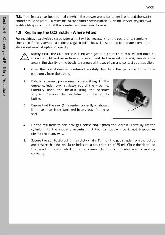
2. Following correct procedures for safe lifting, lift the empty cylinder c/w regulator out of the machine. Carefully undo the locknut using the spanner supplied. Remove the regulator from the empty bottle.
3. Ensure that the seal (1) is seated correctly as shown. If the seal has been damaged in any way, fit a new seal.
4. Fit the regulator to the new gas bottle and tighten the locknut. Carefully lift the cylinder into the machine ensuring that the gas supply pipe is not trapped or obstructed in any way.
5. Secure the gas bottle using the safety chain. Turn on the gas supply from the bottle and ensure that the regulator indicates a gas pressure of 35 psi. Close the door and test vend the carbonated drinks to ensure that the carbonator unit is working correctly.
1
Section 5 – Service Keypad Functions 19
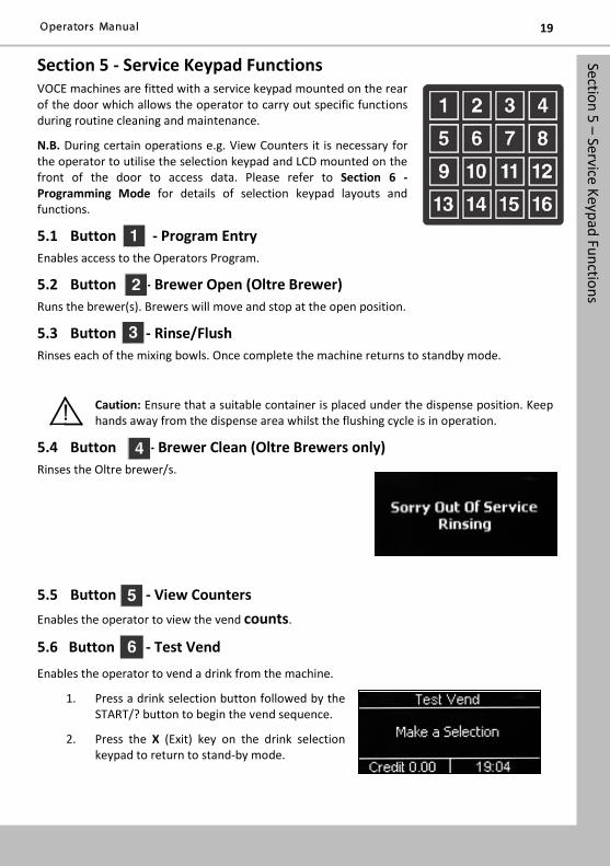
Section 5 - Service Keypad Functions VOCE machines are fitted with a service keypad mounted on the rear of the door which allows the operator to carry out specific functions during routine cleaning and maintenance.
N.B. During certain operations e.g. View Counters it is necessary for the operator to utilise the selection keypad and LCD mounted on the front of the door to access data. Please refer to Section 6 - Programming Mode for details of selection keypad layouts and functions.
5.1 Button - Program Entry Enables access to the Operators Program.
5.2 Button - Brewer Open (Oltre Brewer) Runs the brewer(s). Brewers will move and stop at the open position.
5.3 Button - Rinse/Flush Rinses each of the mixing bowls. Once complete the machine returns to standby mode.
Caution: Ensure that a suitable container is placed under the dispense position. Keep hands away from the dispense area whilst the flushing cycle is in operation.
5.4 Button - Brewer Clean (Oltre Brewers only) Rinses the Oltre brewer/s.
5.5 Button - View Counters Enables the operator to view the vend counts.
5.6 Button - Test Vend
Enables the operator to vend a drink from the machine.
1. Press a drink selection button followed by the START/? button to begin the vend sequence.
2. Press the X (Exit) key on the drink selection keypad to return to stand-by mode.
Section 5 – Service Keypad Functions
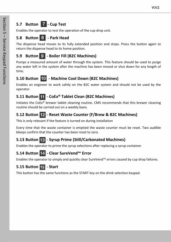
5.7 Button - Cup Test Enables the operator to test the operation of the cup drop unit.
5.8 Button - Park Head The dispense head moves to its fully extended position and stops. Press the button again to return the dispense head to its home position.
5.9 Button - Boiler Fill (B2C Machines) Pumps a measured amount of water through the system. This feature should be used to purge any water left in the system after the machine has been moved or shut down for any length of time.
5.10 Button - Machine Cool Down (B2C Machines) Enables an engineer to work safely on the B2C water system and should not be used by the operator.
5.11 Button - CoEx® Tablet Clean (B2C Machines) Initiates the CoEx® brewer tablet cleaning routine. CMS recommends that this brewer cleaning routine should be carried out on a weekly basis.
5.12 Button - Reset Waste Counter (F/Brew & B2C Machines) This is only relevant if the feature is turned on during installation
Every time that the waste container is emptied the waste counter must be reset. Two audible bleeps confirm that the counter has been reset to zero.
5.13 Button - Syrup Prime (Still/Carbonated Machines) Enables the operator to prime the syrup selections after replacing a syrup container.
5.14 Button - Clear SureVend™ Error Enables the operator to simply and quickly clear SureVend™ errors caused by cup drop failures.
5.15 Button - Start This button has the same functions as the START key on the drink selection keypad.
Section 6 – Programm
ing Mode
21
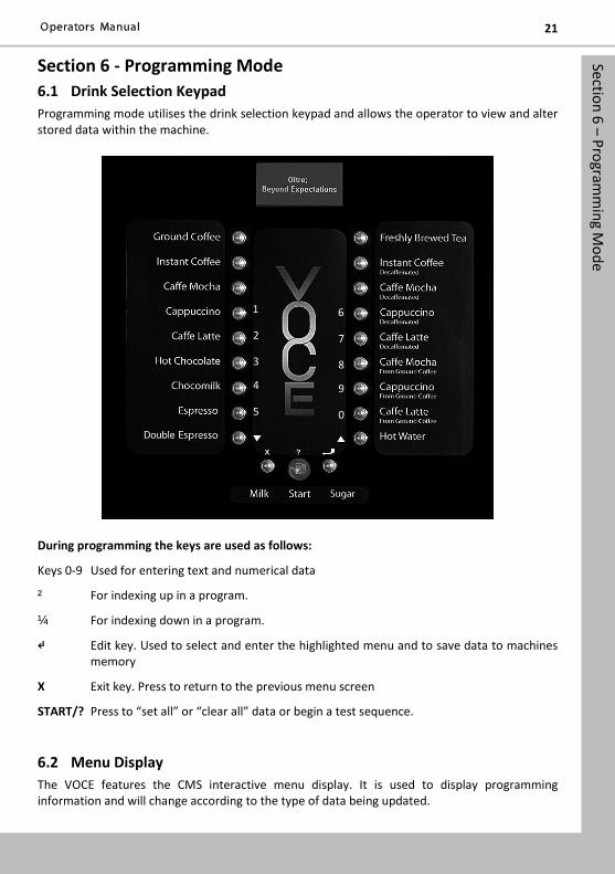
Section 6 - Programming Mode 6.1 Drink Selection Keypad Programming mode utilises the drink selection keypad and allows the operator to view and alter stored data within the machine.
During programming the keys are used as follows:
Keys 0-9 Used for entering text and numerical data
² For indexing up in a program.
¼ For indexing down in a program.
↵ Edit key. Used to select and enter the highlighted menu and to save data to machines memory
X Exit key. Press to return to the previous menu screen
START/? Press to “set all” or “clear all” data or begin a test sequence.
6.2 Menu Display The VOCE features the CMS interactive menu display. It is used to display programming information and will change according to the type of data being updated.
1
2
3
4
5
6
7
8
9
0
?
X
Section 6 – Programm
ing Mode
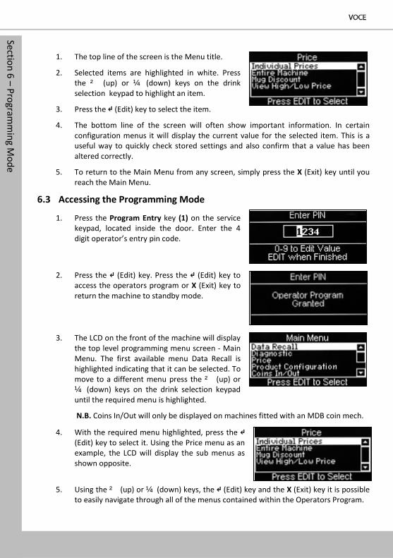
1. The top line of the screen is the Menu title.
2. Selected items are highlighted in white. Press the ² (up) or ¼ (down) keys on the drink selection keypad to highlight an item.
3. Press the ↵ (Edit) key to select the item.
4. The bottom line of the screen will often show important information. In certain configuration menus it will display the current value for the selected item. This is a useful way to quickly check stored settings and also confirm that a value has been altered correctly.
5. To return to the Main Menu from any screen, simply press the X (Exit) key until you reach the Main Menu.
6.3 Accessing the Programming Mode
1. Press the Program Entry key (1) on the service keypad, located inside the door. Enter the 4 digit operator’s entry pin code.
2. Press the ↵ (Edit) key. Press the ↵ (Edit) key to access the operators program or X (Exit) key to return the machine to standby mode.
3. The LCD on the front of the machine will display the top level programming menu screen - Main Menu. The first available menu Data Recall is highlighted indicating that it can be selected. To move to a different menu press the ² (up) or ¼ (down) keys on the drink selection keypad until the required menu is highlighted.
N.B. Coins In/Out will only be displayed on machines fitted with an MDB coin mech.
4. With the required menu highlighted, press the ↵ (Edit) key to select it. Using the Price menu as an example, the LCD will display the sub menus as shown opposite.
5. Using the ² (up) or ¼ (down) keys, the ↵ (Edit) key and the X (Exit) key it is possible to easily navigate through all of the menus contained within the Operators Program.
Section 6 – Programm
ing Mode
23
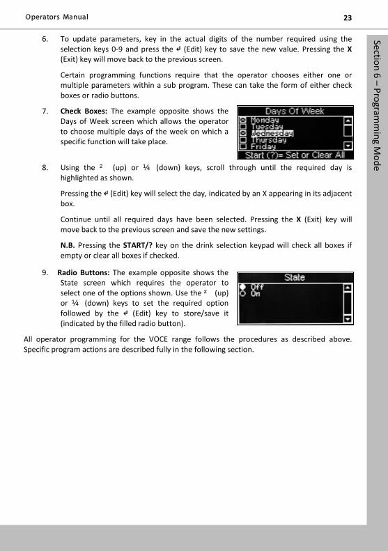
6. To update parameters, key in the actual digits of the number required using the selection keys 0-9 and press the ↵ (Edit) key to save the new value. Pressing the X (Exit) key will move back to the previous screen.
Certain programming functions require that the operator chooses either one or multiple parameters within a sub program. These can take the form of either check boxes or radio buttons.
7. Check Boxes: The example opposite shows the Days of Week screen which allows the operator to choose multiple days of the week on which a specific function will take place.
8. Using the ² (up) or ¼ (down) keys, scroll through until the required day is highlighted as shown.
Pressing the ↵ (Edit) key will select the day, indicated by an X appearing in its adjacent box.
Continue until all required days have been selected. Pressing the X (Exit) key will move back to the previous screen and save the new settings.
N.B. Pressing the START/? key on the drink selection keypad will check all boxes if empty or clear all boxes if checked.
9. Radio Buttons: The example opposite shows the State screen which requires the operator to select one of the options shown. Use the ² (up) or ¼ (down) keys to set the required option followed by the ↵ (Edit) key to store/save it (indicated by the filled radio button).
All operator programming for the VOCE range follows the procedures as described above. Specific program actions are described fully in the following section.
Section 7 – Operators Program
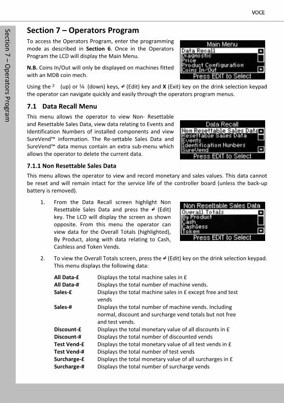
Section 7 – Operators Program To access the Operators Program, enter the programming mode as described in Section 6. Once in the Operators Program the LCD will display the Main Menu.
N.B. Coins In/Out will only be displayed on machines fitted with an MDB coin mech.
Using the ² (up) or ¼ (down) keys, ↵ (Edit) key and X (Exit) key on the drink selection keypad the operator can navigate quickly and easily through the operators program menus.
7.1 Data Recall Menu This menu allows the operator to view Non- Resettable and Resettable Sales Data, view data relating to Events and Identification Numbers of installed components and view SureVend™ information. The Re-settable Sales Data and SureVend™ data menus contain an extra sub-menu which allows the operator to delete the current data.
7.1.1 Non Resettable Sales Data This menu allows the operator to view and record monetary and sales values. This data cannot be reset and will remain intact for the service life of the controller board (unless the back-up battery is removed).
1. From the Data Recall screen highlight Non Resettable Sales Data and press the ↵ (Edit) key. The LCD will display the screen as shown opposite. From this menu the operator can view data for the Overall Totals (highlighted), By Product, along with data relating to Cash, Cashless and Token Vends.
2. To view the Overall Totals screen, press the ↵ (Edit) key on the drink selection keypad. This menu displays the following data:
All Data-£ Displays the total machine sales in £ All Data-# Displays the total number of machine vends. Sales-£ Displays the total machine sales in £ except free and test
vends Sales-# Displays the total number of machine vends. Including
normal, discount and surcharge vend totals but not free and test vends.
Discount-£ Displays the total monetary value of all discounts in £ Discount-# Displays the total number of discounted vends Test Vend-£ Displays the total monetary value of all test vends in £ Test Vend-# Displays the total number of test vends Surcharge-£ Displays the total monetary value of all surcharges in £ Surcharge-# Displays the total number of surcharge vends
Section 7 – Operators Program
25
Free Vend-£ Displays the total monetary value of all free vends in £ Free Vend-# Displays the total number of free vends
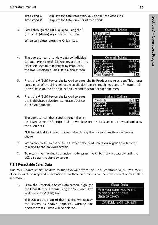
3. Scroll through the list displayed using the ² (up) or ¼ (down) keys to view the data.
When complete, press the X (Exit) key.
4. The operator can also view data by individual product. Press the ¼ (down) key on the drink selection keypad to highlight By Product on the Non Resettable Sales Data menu screen.
5. Press the ↵ (Edit) key on the keypad to enter the By Product menu screen. This menu contains all of the drink selections available from the machine. Use the ² (up) or ¼ (down) keys on the drink selection keypad to scroll through the menu.
6. Press the ↵ (Edit) key on the keypad to enter the highlighted selection e.g. Instant Coffee. As shown opposite.
The operator can then scroll through the list displayed using the ² (up) or ¼ (down) keys on the drink selection keypad and view the audit data.
N.B. Individual By Product screens also display the price set for the selection as shown
7. When complete, press the X (Exit) key on the drink selection keypad to return the machine to the previous screen.
8. To return the machine to standby mode, press the X (Exit) key repeatedly until the LCD displays the standby screen.
7.1.2 Resettable Sales Data This menu contains similar data to that available from the Non Resettable Sales Data menu. Once viewed the required information from these sub-menus can be deleted vi athe Clear Data sub-menu.
1. From the Resettable Sales Data screen, highlight the Clear Data sub menu using the ¼ (down) key and press the ↵ (Edit) key.
The LCD on the front of the machine will display the screen as shown opposite, warning the operator that all data will be deleted.
Section 7 – Operators Program
Either press the ↵ (Edit) key to clear the data or press the X (Exit) key to exit the menu without clearing the data.
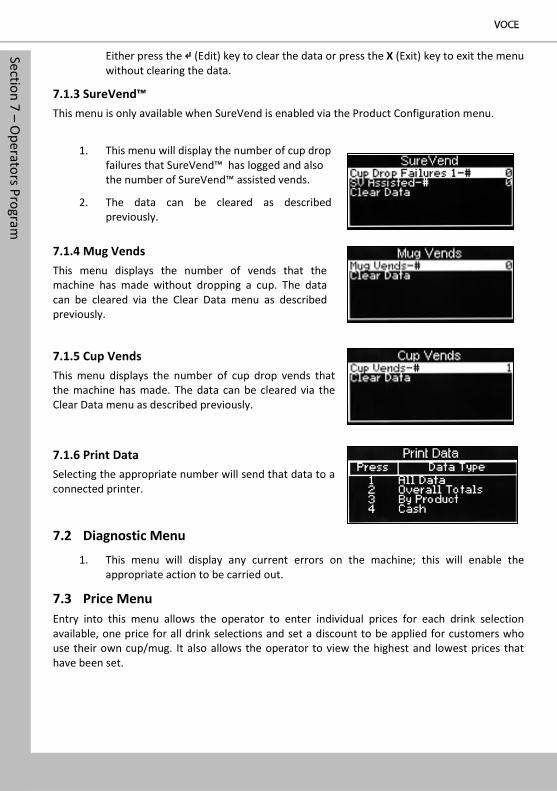
7.1.3 SureVend™ This menu is only available when SureVend is enabled via the Product Configuration menu.
1. This menu will display the number of cup drop failures that SureVend™ has logged and also the number of SureVend™ assisted vends.
2. The data can be cleared as described previously.
7.1.4 Mug Vends This menu displays the number of vends that the machine has made without dropping a cup. The data can be cleared via the Clear Data menu as described previously.
7.1.5 Cup Vends This menu displays the number of cup drop vends that the machine has made. The data can be cleared via the Clear Data menu as described previously.
7.1.6 Print Data Selecting the appropriate number will send that data to a connected printer.
7.2 Diagnostic Menu
1. This menu will display any current errors on the machine; this will enable the appropriate action to be carried out.
7.3 Price Menu Entry into this menu allows the operator to enter individual prices for each drink selection available, one price for all drink selections and set a discount to be applied for customers who use their own cup/mug. It also allows the operator to view the highest and lowest prices that have been set.
Section 7 – Operators Program
27
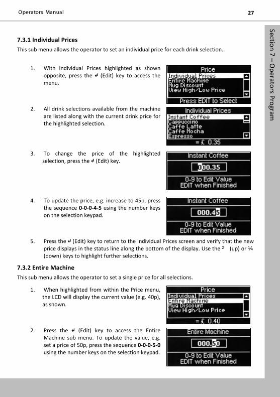
7.3.1 Individual Prices This sub menu allows the operator to set an individual price for each drink selection.
1. With Individual Prices highlighted as shown opposite, press the ↵ (Edit) key to access the menu.
2. All drink selections available from the machine are listed along with the current drink price for the highlighted selection.
3. To change the price of the highlighted selection, press the ↵ (Edit) key.
4. To update the price, e.g. increase to 45p, press the sequence 0-0-0-4-5 using the number keys on the selection keypad.
5. Press the ↵ (Edit) key to return to the Individual Prices screen and verify that the new price displays in the status line along the bottom of the display. Use the ² (up) or ¼ (down) keys to highlight further selections.
7.3.2 Entire Machine This sub menu allows the operator to set a single price for all selections.
1. When highlighted from within the Price menu, the LCD will display the current value (e.g. 40p), as shown.
2. Press the ↵ (Edit) key to access the Entire Machine sub menu. To update the value, e.g. set a price of 50p, press the sequence 0-0-0-5-0 using the number keys on the selection keypad.
Section 7 – Operators Program
3. Press the ↵ (Edit) key to return to the Price menu screen and verify that the new price displays in the status line along the bottom of the display.
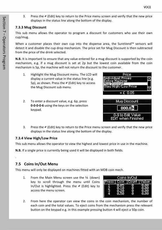
7.3.3 Mug Discount This sub menu allows the operator to program a discount for customers who use their own cup/mug.
When a customer places their own cup into the dispense area, the SureVend™ sensors will detect it and disable the cup drop mechanism. The price set for Mug Discount is then subtracted from the price of the drink selected.
N.B. It is important to ensure that any value entered for a mug discount is supported by the coin mechanism, e.g. if a mug discount is set at 2p but the lowest coin available from the coin mechanism is 5p, the machine will not return the discount to the customer.
1. Highlight the Mug Discount menu. The LCD will display a current value in the status line (e.g. 5p), as shown. Press the ↵ (Edit) key to access the Mug Discount sub menu.
2. To enter a discount value, e.g. 6p, press 0-0-0-0-6 using the keys on the selection keypad.
3. Press the ↵ (Edit) key to return to the Price menu screen and verify that the new price displays in the status line along the bottom of the display.
7.3.4 View High/Low Price This sub menu allows the operator to view the highest and lowest price in use in the machine.
N.B. If a single price is currently being used it will be displayed in both fields.
.
7.5 Coins In/Out Menu This menu will only be displayed on machines fitted with an MDB coin mech.
1. From the Main Menu screen use the ¼ (down) key to scroll through the menu until Coins In/Out is highlighted. Press the ↵ (Edit) key to access the menu screen.
2. From here the operator can view the coins in the coin mechanism, the number of each coin and the total values. To eject coins from the mechanism press the relevant button on the keypad e.g. in this example pressing button 4 will eject a 50p coin.
Section 8 – Dispense Pipe Lengths
29
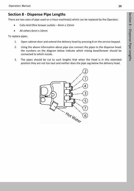
Section 8 - Dispense Pipe Lengths There are two sizes of pipe used on a Voce machine(s) which can be replaced by the Operator,
• CoEx And Oltre brewer outlets – 8mm x 13mm
• All others 6mm x 10mm
To replace pipes.
1. Open cabinet door and extend the delivery head by pressing 8 on the service keypad.
2. Using the above information about pipe size connect the pipes to the dispense head; the numbers on the diagram below indicate which mixing bowl/brewer should be connected to which nozzle.
3. The pipes should be cut to such lengths that when the head is in this extended position they are not too taut and neither does the pipe sag below the delivery head.
Section 9 – Recomm
ended Spare Parts
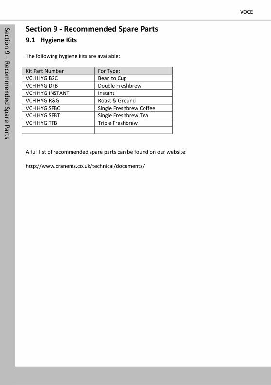
Section 9 - Recommended Spare Parts 9.1 Hygiene Kits
The following hygiene kits are available: Kit Part Number For Type: VCH HYG B2C Bean to Cup VCH HYG DFB Double Freshbrew VCH HYG INSTANT Instant VCH HYG R&G Roast & Ground VCH HYG SFBC Single Freshbrew Coffee VCH HYG SFBT Single Freshbrew Tea VCH HYG TFB Triple Freshbrew A full list of recommended spare parts can be found on our website: http://www.cranems.co.uk/technical/documents/
Section 9 – Recomm
ended Spare Parts
31
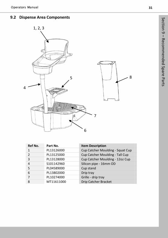
9.2 Dispense Area Components
Ref No. Part No. Item Description 1 PL13126000 Cup Catcher Moulding - Squat Cup 2 PL13125000 Cup Catcher Moulding - Tall Cup 3 PL13128000 Cup Catcher Moulding - 12oz Cup 4 S101142960 Silicon pipe - 16mm OD 5 PL04589000 Cup stand 6 PL13802000 Drip tray 7 PL10274000 Grille - drip tray 8 MT11611000 Drip Catcher Bracket
1, 2, 3
4
5
6
7
8
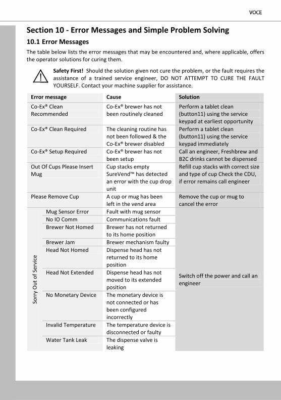
Section 10 - Error Messages and Simple Problem Solving 10.1 Error Messages The table below lists the error messages that may be encountered and, where applicable, offers the operator solutions for curing them.
Safety First! Should the solution given not cure the problem, or the fault requires the assistance of a trained service engineer, DO NOT ATTEMPT TO CURE THE FAULT YOURSELF. Contact your machine supplier for assistance.
Error message Cause Solution
Co-Ex® Clean Recommended
Co-Ex® brewer has not been routinely cleaned
Perform a tablet clean (button11) using the service keypad at earliest opportunity
Co-Ex® Clean Required The cleaning routine has not been followed & the Co-Ex® brewer disabled
Perform a tablet clean (button11) using the service keypad immediately
Co-Ex® Setup Required Co-Ex® brewer has not been setup
Call an engineer, Freshbrew and B2C drinks cannot be dispensed
Out Of Cups Please Insert Mug
Cup stacks empty SureVend™ has detected an error with the cup drop unit
Refill cup stacks with correct size and type of cup Check the CDU, if error remains call engineer
Please Remove Cup A cup or mug has been left in the vend area
Remove the cup or mug to cancel the error
Sorr
y O
ut o
f Ser
vice
Mug Sensor Error Fault with mug sensor
Switch off the power and call an engineer
No IO Comm Communications fault Brewer Not Homed Brewer has not returned
to its home position Brewer Jam Brewer mechanism faulty Head Not Homed Dispense head has not
returned to its home position
Head Not Extended Dispense head has not moved to its extended position
No Monetary Device The monetary device is not connected or has been configured incorrectly
Invalid Temperature The temperature device is disconnected or faulty
Water Tank Leak The dispense valve is leaking
Section 10 – Error Messages and Sim
ple Fault Finding
33
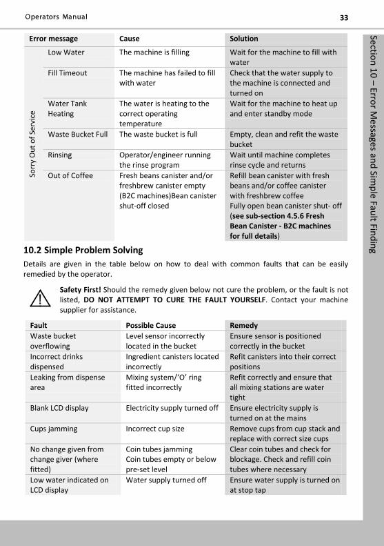
Error message Cause Solution So
rry
Out
of S
ervi
ce
Low Water The machine is filling Wait for the machine to fill with water
Fill Timeout The machine has failed to fill with water
Check that the water supply to the machine is connected and turned on
Water Tank Heating
The water is heating to the correct operating temperature
Wait for the machine to heat up and enter standby mode
Waste Bucket Full The waste bucket is full Empty, clean and refit the waste bucket
Rinsing Operator/engineer running the rinse program
Wait until machine completes rinse cycle and returns
Out of Coffee Fresh beans canister and/or freshbrew canister empty (B2C machines)Bean canister shut-off closed
Refill bean canister with fresh beans and/or coffee canister with freshbrew coffee Fully open bean canister shut- off (see sub-section 4.5.6 Fresh Bean Canister - B2C machines for full details)
10.2 Simple Problem Solving Details are given in the table below on how to deal with common faults that can be easily remedied by the operator.
Safety First! Should the remedy given below not cure the problem, or the fault is not listed, DO NOT ATTEMPT TO CURE THE FAULT YOURSELF. Contact your machine supplier for assistance.
Fault Possible Cause Remedy Waste bucket overflowing
Level sensor incorrectly located in the bucket
Ensure sensor is positioned correctly in the bucket
Incorrect drinks dispensed
Ingredient canisters located incorrectly
Refit canisters into their correct positions
Leaking from dispense area
Mixing system/ʻOʼ ring fitted incorrectly
Refit correctly and ensure that all mixing stations are water tight
Blank LCD display Electricity supply turned off Ensure electricity supply is turned on at the mains
Cups jamming Incorrect cup size Remove cups from cup stack and replace with correct size cups
No change given from change giver (where fitted)
Coin tubes jamming Coin tubes empty or below pre-set level
Clear coin tubes and check for blockage. Check and refill coin tubes where necessary
Low water indicated on LCD display
Water supply turned off Ensure water supply is turned on at stop tap
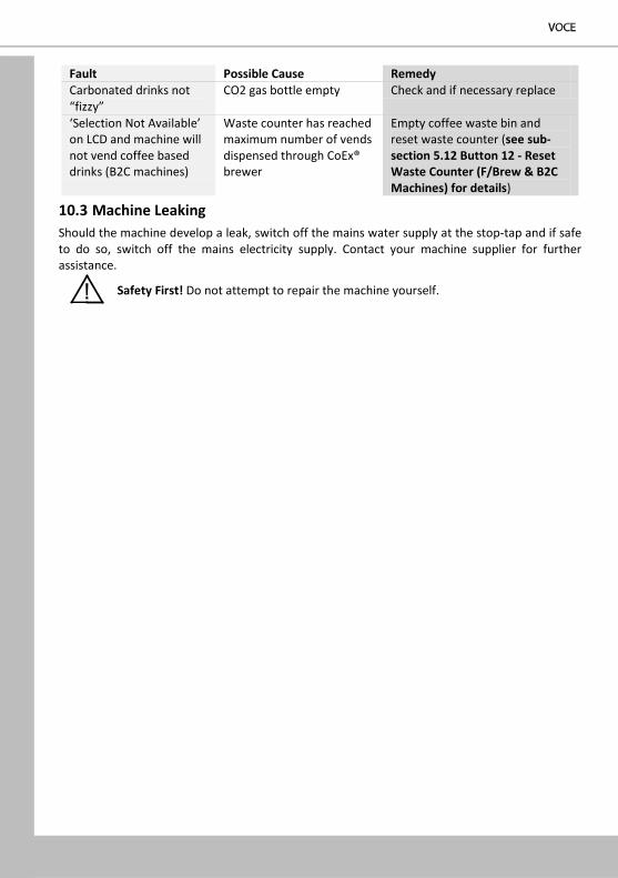
Fault Possible Cause Remedy Carbonated drinks not “fizzy”
CO2 gas bottle empty Check and if necessary replace
ʻSelection Not Availableʼ on LCD and machine will not vend coffee based drinks (B2C machines)
Waste counter has reached maximum number of vends dispensed through CoEx® brewer
Empty coffee waste bin and reset waste counter (see sub-section 5.12 Button 12 - Reset Waste Counter (F/Brew & B2C Machines) for details)
10.3 Machine Leaking Should the machine develop a leak, switch off the mains water supply at the stop-tap and if safe to do so, switch off the mains electricity supply. Contact your machine supplier for further assistance.
Safety First! Do not attempt to repair the machine yourself.
35
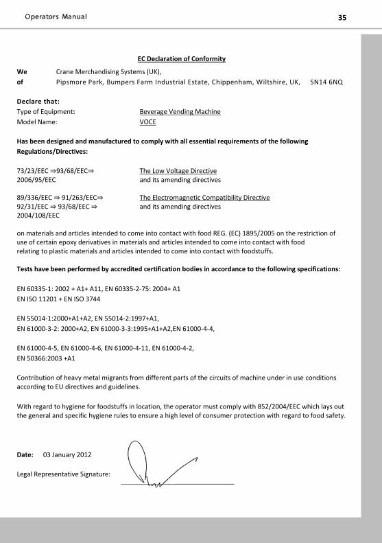
EC Declaration of Conformity
We Crane Merchandising Systems (UK), of Pipsmore Park, Bumpers Farm Industrial Estate, Chippenham, Wiltshire, UK, SN14 6NQ
Declare that: Type of Equipment: Beverage Vending Machine Model Name: VOCE
Has been designed and manufactured to comply with all essential requirements of the following Regulations/Directives:
73/23/EEC ⇒93/68/EEC⇒ The Low Voltage Directive 2006/95/EEC and its amending directives 89/336/EEC ⇒ 91/263/EEC⇒ The Electromagnetic Compatibility Directive 92/31/EEC ⇒ 93/68/EEC ⇒ and its amending directives 2004/108/EEC
on materials and articles intended to come into contact with food REG. (EC) 1895/2005 on the restriction of use of certain epoxy derivatives in materials and articles intended to come into contact with food
relating to plastic materials and articles intended to come into contact with foodstuffs. Tests have been performed by accredited certification bodies in accordance to the following specifications:
EN 60335-1: 2002 + A1+ A11, EN 60335-2-75: 2004+ A1 EN ISO 11201 + EN ISO 3744
EN 55014-1:2000+A1+A2, EN 55014-2:1997+A1, EN 61000-3-2: 2000+A2, EN 61000-3-3:1995+A1+A2,EN 61000-4-4,
EN 61000-4-5, EN 61000-4-6, EN 61000-4-11, EN 61000-4-2, EN 50366:2003 +A1
Contribution of heavy metal migrants from different parts of the circuits of machine under in use conditions according to EU directives and guidelines.
With regard to hygiene for foodstuffs in location, the operator must comply with 852/2004/EEC which lays out the general and specific hygiene rules to ensure a high level of consumer protection with regard to food safety.
Date: 03 January 2012
Legal Representative Signature:
Visit our Spares Online for your Voce parts and for other parts and documentation for the Crane range. To find this and other manuals and technical information for the Crane Merchandising Systems range go to: www.cmsspares.eu
Visit the Tech Zone on our website to find this and other manuals and technical information for the Crane Merchandising systems range: www.cranems.co.uk / technical/
Related Documents