1 Overpressure Leak Detector Installation and User Manual Model LD-UPP-3 Franklin Fueling Systems • 3760 Marsh Rd. • Madison, WI 53718 USA Tel: +1 608 838 8786 • 800 225 9787 • Fax: +1 608 838 6433 • www.franklinfueling.com

Welcome message from author
This document is posted to help you gain knowledge. Please leave a comment to let me know what you think about it! Share it to your friends and learn new things together.
Transcript
1
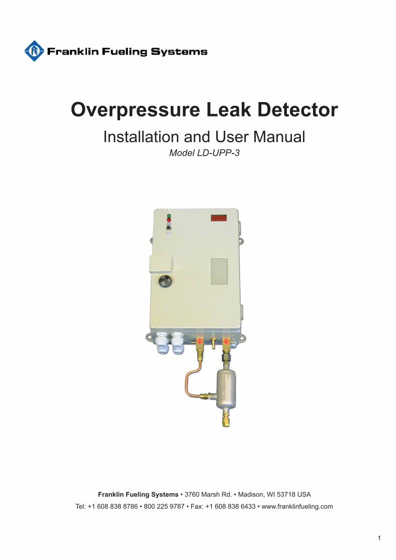
Overpressure Leak DetectorInstallation and User Manual
Model LD-UPP-3
Franklin Fueling Systems • 3760 Marsh Rd. • Madison, WI 53718 USA
Tel: +1 608 838 8786 • 800 225 9787 • Fax: +1 608 838 6433 • www.franklinfueling.com
2
ContentsSubject..............................................................................................................................3
Operative Range ..............................................................................................................3Requirements for interstitial spaces ........................................................................................3Pipes .......................................................................................................................................3Fittings ....................................................................................................................................3Liquid to be conveyed and leak detection medium .................................................................3
Functional Description ...................................................................................................... 3Switch and pressure values ....................................................................................................3
Normal operation .............................................................................................................4Functions in case of a leak .....................................................................................................4Air drying / dry filter ..................................................................................................................4Description of indicator and operating elements .....................................................................4
Operating functions via push buttons ........................................................................................... 4
Installation Instructions ..................................................................................................4General notes .........................................................................................................................4Personal Protective Equipment ..............................................................................................4Installation of the Leak Detector .............................................................................................5Installation of connections (leak detector - interstitial space) ............................................... 5Installation of the dry filter .......................................................................................................5Power Specifications ..............................................................................................................5
Initial Operation / Repair .................................................................................................5
Operating instructions ....................................................................................................6General notes .........................................................................................................................6Maintenance ...........................................................................................................................6
Performed by the operator ........................................................................................................... 6Maintenance work and functional tests performed by qualified personnel only ................................6
Intended use ...........................................................................................................................6Functional testing ....................................................................................................................6
Checking the Free Passage of Air in the Interstitial Space ........................................................... 7Testing the switch values with a testing device ............................................................................. 7Testing the switching values without a testing device ................................................................... 7Check the overpressure valve ....................................................................................................... 7Tightness test ................................................................................................................................ 8Set up the equipment ready for operation ..................................................................................... 8
Alarm / Malfunction ..................................................................................................................8
Removal............................................................................................................................8
Marking .............................................................................................................................8
Abbreviations...................................................................................................................8
Diagrams ..........................................................................................................................9
Appendix TD ..................................................................................................................16Technical Data ......................................................................................................................16
Electrical data .............................................................................................................................. 16Pneumatic data (requirements for the test measuring instrument) ............................................. 16
Dry Filters.............................................................................................................................16Dry filters for underground pipes: ................................................................................................ 16
Statement on the cross-sections of the connecting lines between leak detector LD-UPP-3 and the interstitial spaces....................................................17
DImensions / Drilling ......................................................................................................18
Work Sheet AB-820 500.................................................................................................20Pneumatic connections .........................................................................................................20
Declaration of Conformity ............................................................................................22
3
Subject
LD-UPP-3 - Pressure leak detector for secondary contained (double walled) pipes, secondary contained fittings or a combination of the above with air used as the leak detection medium.
The monitoring pressure is created by a built-in pump which draws air from the environment.
Operative RangeRequirements for interstitial spaces
• Proof of pressure resistance of the interstitial space (see the Tightness Testing Section page 8).
• Proof of suitability of the interstitial space. • Tightness of the interstitial space (see the
Tightness Testing Section page 8).• The number of interstitial spaces to be monitored
depends on the total interstitial volume. According to EN 13160, 10m3 must not be exceeded. For reasons of control of the tightness of interstitial spaces it is recommended not to exceed 4 m3. Pipe length (per pipe run) to be monitored may not exceed 2500 m and must correspond with the specifications for the approval of the pipe.
Pipes and FittingsSecondary containment UPP pipe and fittings approved to EN14125.
Liquid to be conveyed and leak detection medium
• Liquids which are hazardous to the environment with a flash point > 55°C.
• Liquids which are hazardous to the environment with a flash point < 55°C. ONLY for secondary contained pipes / fittings approved to EN14125. On pipes / fittings which are permanently filled with liquid, it must be ensured that the equipment carrying the product (i.e. delivery pumps) is suitable for zone 0, as air is forced into the product in the event of a leak.
• The product being conveyed must not react with the leak detection medium.
• The resistance of the pipes / fittings to the material being conveyed must be verified by third parties (e.g. Operator, manufacturer of the pipeline, etc).
Functional Description
The pressure leak detector LD-UPP-3 monitors both walls of the secondary contained system for leaks. The monitoring pressure during operation is higher than any pressure on the inner or outer wall, so that leaks will be indicated through falling pressure.
In order to build up the pressure, air is drawn from the atmosphere by the integrated pump via a dry filter and then pumped to the interstitial space(s).
The dry filter dries the incoming air to a relative humidity of approximately 10%. The drying process is necessary in order to eliminate any accumulation of moisture or condensation in the interstitial space. Used dry filter cartridges should be regenerated or replaced.
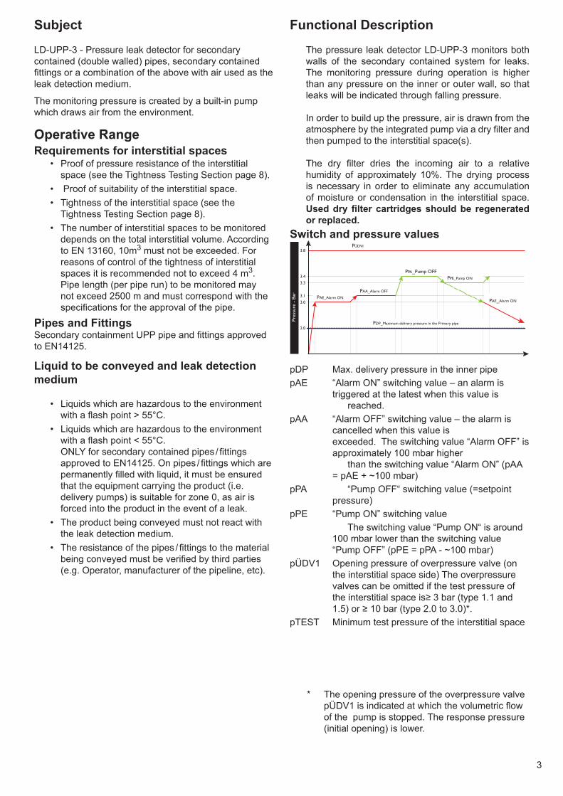
Switch and pressure values
2.0
3.0
3.1
3.3
3.4
PAE_Alarm ON
PAA_Alarm OFF
PPA_Pump OFFPPE_Pump ON
PDP_Maximum delivery pressure in the Primary pipe
Pres
sure
- B
ar
PAE_Alarm ON
3.8PÜDVI
pDP Max. delivery pressure in the inner pipepAE “Alarm ON” switching value – an alarm is
triggered at the latest when this value is reached.
pAA “Alarm OFF” switching value – the alarm is cancelled when this value is exceeded. The switching value “Alarm OFF” is approximately 100 mbar higher than the switching value “Alarm ON” (pAA = pAE + ~100 mbar)
pPA “Pump OFF“ switching value (=setpoint pressure)
pPE “Pump ON” switching value The switching value “Pump ON“ is around
100 mbar lower than the switching value “Pump OFF” (pPE = pPA - ~100 mbar)
pÜDV1 Opening pressure of overpressure valve (on the interstitial space side) The overpressure valves can be omitted if the test pressure of the interstitial space is≥ 3 bar (type 1.1 and 1.5) or ≥ 10 bar (type 2.0 to 3.0)*.
pTEST Minimum test pressure of the interstitial space
* The opening pressure of the overpressure valve pÜDV1 is indicated at which the volumetric flow of the pump is stopped. The response pressure (initial opening) is lower.
4
Normal operationThe leak detector is connected via the connecting line(s) to the interstitial space(s). The overpressure generated by the pump is measured via a pressure sensor and regulated.
When the operating pressure (Pump OFF) is reached the pump is switched off. Due to leaks in the leak detection system which are unavoidable, the pressure will start to slowly fall. When the switching pressure “Pump ON” is reached the pump is switched on and the system builds operating pressure back up again.
During normal operation, the leak detector fluctuates between these two pressure values, with short run-up times and longer standstill times which depend on the tightness and temperature fluctuations of the overall site.
Functions in case of a leakIf there is a leak in the inner or outer wall, air will leak from the interstitial space. The pressure will drop until the pump is switched on in order to restore operating pressure. If the volumetric flow escaping through the leak is greater than the (limited) delivery rate of the pump then the pressure in the system drops and the pump runs continuously.
Any increase in the size of the leak leads to a further pressure loss until eventually the alarm pressure is reached. At this point the system will generate visual, audible and potential-free alarm outputs.
Air drying / dry filterThe air supplied to the interstitial space is passed through a dry filter in the intake line. The dry filter dries the air to a relative humidity of around 10% in order to prevent corrosion and accumulation of condensation in the interstitial space.
The dry filter is designed to last for a year provided the equipment is used for its proper intended use and no additional temperature fluctuations occur.
Initially the dry filter is an orange colour, but this fades to a colourless (or green) state when the filter has been used up. Once the filter cartridge has been used up it should be replaced or regenerated.
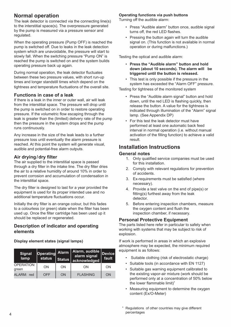
Description of indicator and operating elements
Display element states (signal lamps)
Signal lamp
Operating status
Alarm
Status
Alarm, audible alarm signal
acknowledged
Device fault
OPERATION: green ON ON ON ON
ALARM: red OFF ON FLASHING ON
Operating functions via push buttonsTurning off the audible alarm:
• Press “Audible alarm” button once, audible signal turns off, the red LED flashes.
• Pressing the button again will turn the audible signal on. (This function is not available in normal operation or during malfunctions.)
Testing the optical and audible alarm:
• Press the “Audible alarm” button and hold down (about 10 seconds). The alarm will be triggered until the button is released.
• This test is only possible if the pressure in the system has exceeded the “Alarm OFF” pressure.
Testing for tightness of the monitored system
• Press the “Audible alarm signal” button and hold down, until the red LED is flashing quickly, then release the button. A value for the tightness is indicated through illumination of the “Alarm” signal lamp. (See Appendix DP)
• For this test the leak detector must have performed at least one automatic back feed interval in normal operation (i.e. without manual activation of the filling function) to achieve a valid result.
Installation InstructionsGeneral notes
1. Only qualified service companies must be used for this installation.
2. Comply with relevant regulations for prevention of accidents.
3. Ex-requirements must be satisfied (where necessary).
4. Provide a test valve on the end of pipe(s) or fitting(s) furthest away from the leak detector.
5. Before entering inspection chambers, measure the oxygen content and flush the inspection chamber, if necessary.
Personal Protective EquipmentThe parts listed here refer in particular to safety when working with systems that may be subject to risk of explosion.
If work is performed in areas in which an explosive atmosphere may be expected, the minimum required equipment is as follows:
• Suitable clothing (risk of electrostatic charge) • Suitable tools (in accordance with EN 1127) • Suitable gas warning equipment calibrated to
the existing vapor-air mixture (work should be performed only at a concentration of 50% below the lower flammable limit)*
• Measuring equipment to determine the oxygen content (Ex/O-Meter)
* Regulations of other countries may give different percentages
5
Installation of the Leak Detector• Generally mounted on walls with plugs and screws.• In a dry room, or outdoors in a suitable housing.• NOT in hazardous (classified) areas (danger of
explosions)• The distance between the leak detector and the
interstitial space should be kept as short as possible (refer also to the next section).
Installation of connections (leak detector - interstitial space)
• Metal (generally Cu - Copper) or plastic tubes with a minimum pressure resistance corresponding with the test pressure in the interstitial space. Also applies to fittings and screwed connections. (Observe temperature range, especially when using plastic tubes).
• Clear inside diameter at least 6 mm.• 50 m of tube should not be exceeded. If 50 m is
exceeded install tube with larger inside diameter and ensure fittings also have a larger inside diameter.
• The full cross-section must be maintained. Do not pinch or kink tube*.
• Metal or plastic tubes that are installed underground or above ground should be installed inside a conduit.
• The conduit should be sealed.• The pressure and measuring lines can be
combined underneath the leak detector via pulsation damper 107 (see installation examples).
• Avoid any build up of electrostatic charge (e.g. During the pulling of lines).
• For details regarding connection systems, see Work Sheet AB-820 500.
Installation of the dry filter• Preferably close to the leak detector.• Vertical with the intake opening facing down, using
the enclosed installation materials.• The dry filter and the intake connection port of the
leak detector should be connected via a PVC hose (or similar).
Power Specifications• Power supply: According to label.• Fixed wiring, i.e. no plug or switch connections.• The regulations of the electricity supply companies
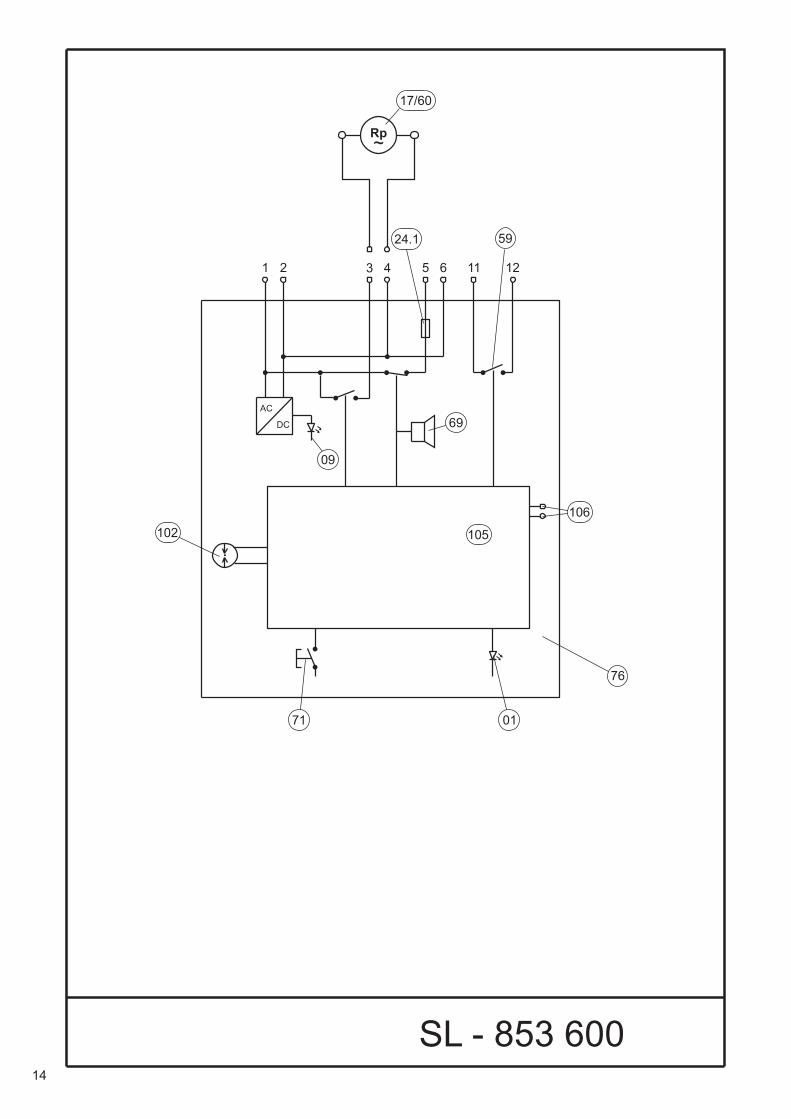
must be satisfied.• Terminal assignment: (see also SL-853 600)
1 / 2 Mains connection
3 / 4 Assigned (to the internal pump)
5 / 6 External signal (in the event of an alarm, mains voltage is present here - it is switched off by pressing the “Audible alarm” button).
11 / 12 Potential-free contacts (open in the event of an alarm and in the event of a power loss)
Initial Operation / Repair
1. Observe all guidelines from section 4.2. If a leak detector is operated on a pipeline that is
already in operation, special protective measures must be taken (for example, checking that the leak detector and/or the interstitial space is free of gas). Additional measures may be necessary depending on the local conditions and must be assessed by qualified personnel.
3. After completion of the pneumatic connection, make the electrical connections.
4. Check that the signal lamps for “Operation” and “Alarm” light up and the audible alarm signal sounds. Turn off the audible alarm, if necessary.
5. Connect the three-way valve 21 in the position “III”, connect a gauge. (Drawing: P-078 000)
6. The leak detection system should be supplied with the operating pressure according to the table on page 6. (Use of an assembly pump, with sufficiently dimensioned dry filter or a nitrogen gas cylinder).
7. Build-up of pressure with the assembly pump or the gas cylinder (observe the pressure settings) - can be performed directly via the pressure line or via the three-way valve 20 (position IV).
Note: If no pressure is built up with the assembly pump (or gas cylinder) connected, then the leak should be located and rectified (if required check that the delivery rate of the assembly pump and the settings of the pressure reducer are correct).
8. Once the operating pressure of the leak detector has been reached (pressure generation inside the leak detector switches off), reconnect the high-pressure line and/or set both valve to “I”, remove the pressure measuring instrument.
9. Test per the Functional Testing section on page 6.
* If required install commercially available shaped section for plastic tubes (observe minimum bending radii)
6
Operating instructionsGeneral notes• If the leak detection system has been properly
installed and is free of leaks, trouble-free operation can be assumed.
• If the pump comes on frequently or runs continuously then this indicates that leaks are present which will require attention within due course.
• In the event of an alarm, determine the cause and correct it immediately.
• Disconnect the power supply to the leak detector whenever performing servicing work on it.
• The signal lamp “Operation” goes out if there is a break in the current supply. Alarm signals are sent out via the potential-free relay contacts (if used).After the interruption in the current supply, the green signal lamp comes back on and the alarm signal which is output via the potential-free contacts is cancelled (unless the pressure has dropped below the alarm pressure while the current supply was interrupted.)
• The filter cartridge should be replaced or regenerated when it changes colour from orange to having no colour (or green, depending on the type of drying material).
MaintenancePerformed by the operator The dry filter should be checked at regular intervals. ¹ The filter cartridge should be replaced or regenerated when it changes colour from orange to having no colour (or green).
Maintenance work and functional tests performed by qualified personnel only ²• Testing once a year for functional and operational
reliability and safety.• Test scope according to Functional Testing section.
¹ A time gap of at least 2 months is recommended.² By a trained specialist with expertise in the
maintenance and servicing of leak detection devices, or under the responsibility of a trained and qualified individual in accordance with the applicable regulations.
Intended use• For secondary contained pipes / fittings• Vapour-air mixtures which may potentially arise due to:
• The liquid being conveyed,• The liquid being conveyed in conjunction with air/
air moisture or condensate• The liquid being conveyed in conjunction with the
materials used must be classifiable in temperature classes T1 to T3 and in explosion group II A or II B.For this type of liquid, the wall on the side of the product being conveyed must be resistant to permeation.
• The feed pressure (in the inner pipe) must be at least 1 bar lower than the minimum alarm pressure.
• The system must be earthed in accordance with applicable regulations.
• Test the tightness of the leak detection system by following the tightness testing section, page 8.
• The leak detection unit must be installed outside the potentially explosive-area.
• Conduits for connecting lines must be sealed gas-tight.
• The leak detector should be (electrically) connected in a way which cannot be switched off.
Functional testingThe functional and operational safety tests must be performed:
• At every commissioning,• In accordance with the intervals listed in section 6.2,• Whenever a fault is rectified.Test scope
1. Coordinate the work to be performed with those responsible for operation on-site, if necessary.
2. Observe the safety instructions for working with the liquids to be conveyed.
3. Replacement or regeneration of the filter cartridge. 4. Check the test valve at the end of the interstitial
space away from the leak detector for tightness and contamination and clean, if necessary.
5. Check the free passage of air through the interstitial space on the next page.
6. Check the Testing the Switch Values section, page 7. Alternatively, refer to the Test the switch values without a testing device section, page 7.
7. Check the overpressure valve section, page 7.8. Check tightness as a part of the annual function
test. See Tightness test, page 8.9. See the setup the equipment ready for operation
section, page 810. Completion of a test report by the qualified
person, with confirmation of functional and operational safety and reliability.
11. Before starting work, we recommend performing the leak test of the system (which is integrated in the leak detector) as described in section 3.5.2, in order to gain an impression of the condition of the system.
7
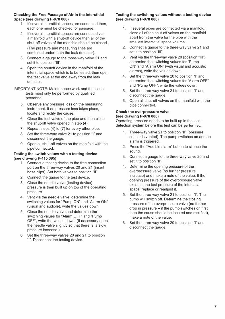
Checking the Free Passage of Air in the Interstitial Space (see drawing P-078 000)
1. If several interstitial spaces are connected then, each one must be checked for passage.
2. If several interstitial spaces are connected via a manifold with a shut-off device then all of the shut-off valves of the manifold should be closed.
(The pressure and measuring lines are combined underneath the leak detector).
3. Connect a gauge to the three-way valve 21 and set it to position “III”.
4. Open the shutoff device in the manifold of the interstitial space which is to be tested, then open the test valve at the end away from the leak detector.
IMPORTANT NOTE: Maintenance work and functional tests must only be performed by qualified personnel.
5. Observe any pressure loss on the measuring instrument. If no pressure loss takes place, locate and rectify the cause.
6. Close the test valve of the pipe and then close the shut-off valve opened in step (4).
7. Repeat steps (4) to (7) for every other pipe.8. Set the three-way valve 21 to position “I” and
disconnect the gauge.9. Open all shut-off valves on the manifold with the
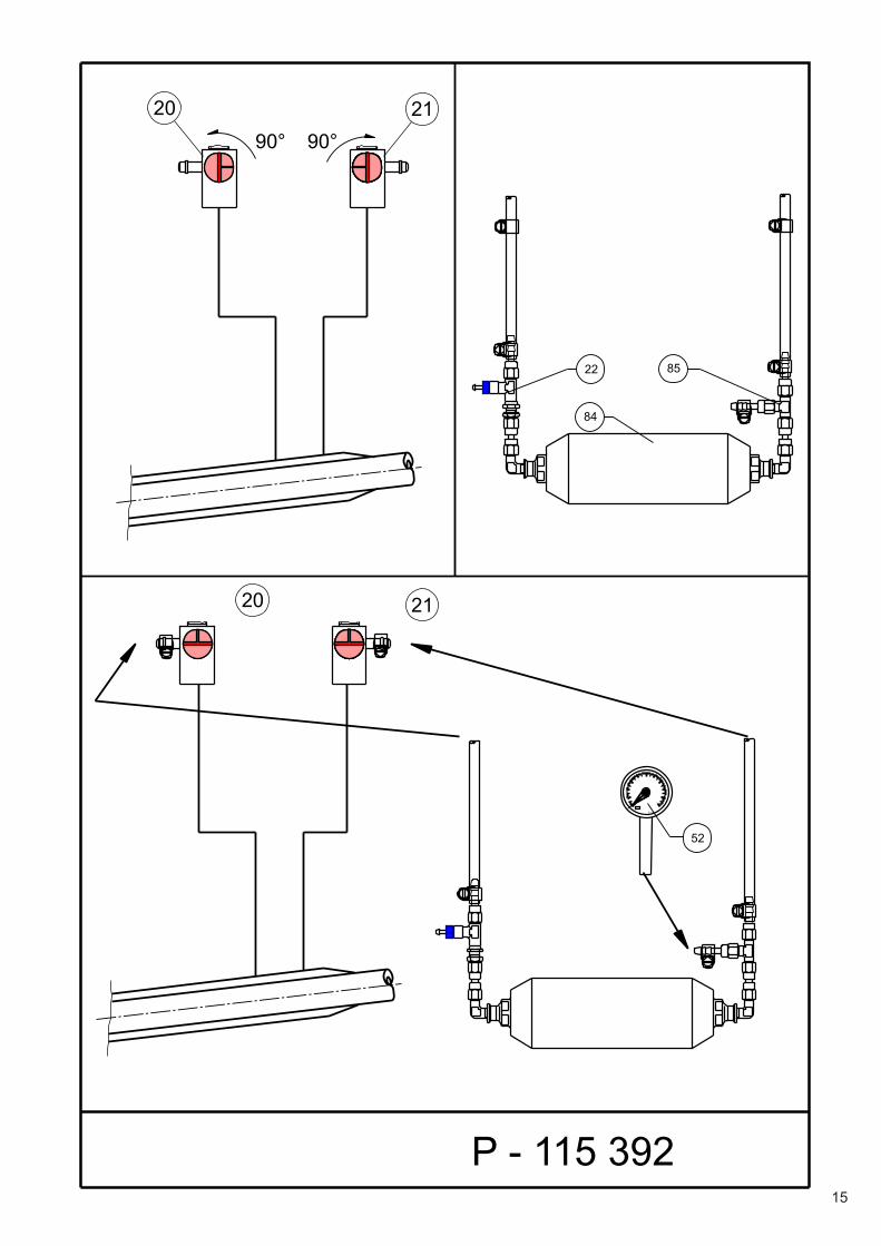
pipe connected.Testing the switch values with a testing device (see drawing P-115 395)
1. Connect a testing device to the free connection port on the three-way valves 20 and 21 (insert hose clips). Set both valves to position “II”.
2. Connect the gauge to the test device.3. Close the needle valve (testing device) –
pressure is then built up on top of the operating pressure.
4. Vent via the needle valve, determine the switching values for “Pump ON” and “Alarm ON” (visual and audible), write the values down.
5. Close the needle valve and determine the switching values for “Alarm OFF” and “Pump OFF”, write the values down. (If necessary open the needle valve slightly so that there is a slow pressure increase.)
6. Set the three-way valves 20 and 21 to position “I”. Disconnect the testing device.
Testing the switching values without a testing device (see drawing P-078 000)
1. If several pipes are connected via a manifold, close all of the shut-off valves on the manifold apart from the valve for the pipe with the smallest interstitial space volume.
2. Connect a gauge to the three-way valve 21 and set it to position “III”.
3. Vent via the three-way valve 20 (position “III”), determine the switching values for “Pump ON” and “Alarm ON” (with visual and acoustic alarms), write the values down.
4. Set the three-way valve 20 to position “I” and determine the switching values for “Alarm OFF” and “Pump OFF”, write the values down.
5. Set the three-way valve 21 to position “I” and disconnect the gauge.
6. Open all shut-off valves on the manifold with the pipe connected.
Check the overpressure valve (see drawing P-078 000)Operating pressure needs to be built up in the leak detection system before this test can be performed.
1. Three-way valve 21 to position “II” (pressure sensor is vented). The pump switches on and an alarm is triggered.
2. Press the “Audible alarm” button to silence the sound.
3. Connect a gauge to the three-way valve 20 and set it to position “II”.
4. Determine the opening pressure of the overpressure valve (no further pressure increase) and make a note of the value. If the opening pressure of the overpressure valve exceeds the test pressure of the interstitial space, replace or readjust it.
5. Set the three-way valve 21 to position “I”. The pump will switch off. Determine the closing pressure of the overpressure valve (no further drop in pressure – if the pump switches on first then the cause should be located and rectified), make a note of the value.
6. Set the three-way valve 20 to position “I” and disconnect the gauge.
8
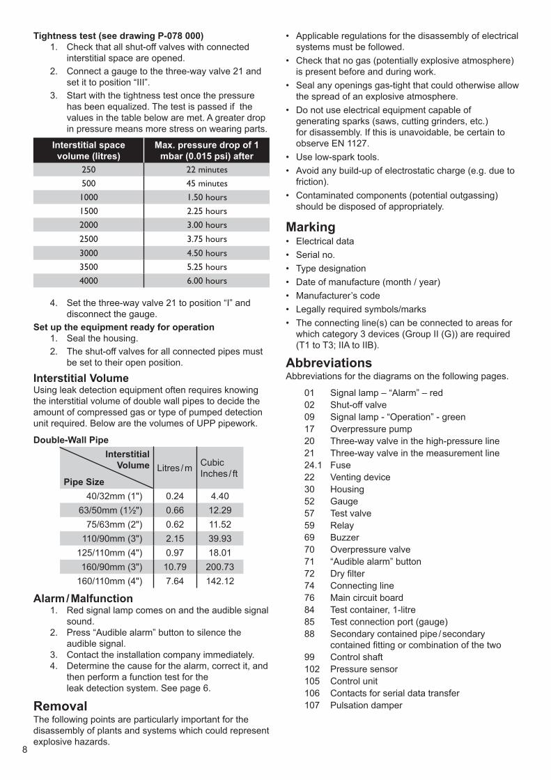
Tightness test (see drawing P-078 000)1. Check that all shut-off valves with connected
interstitial space are opened.2. Connect a gauge to the three-way valve 21 and
set it to position “III”.3. Start with the tightness test once the pressure
has been equalized. The test is passed if the values in the table below are met. A greater drop in pressure means more stress on wearing parts.
Interstitial space volume (litres)
Max. pressure drop of 1 mbar (0.015 psi) after
250 22 minutes500 45 minutes1000 1.50 hours1500 2.25 hours2000 3.00 hours
2500 3.75 hours
3000 4.50 hours3500 5.25 hours4000 6.00 hours
4. Set the three-way valve 21 to position “I” and disconnect the gauge.
Set up the equipment ready for operation1. Seal the housing.2. The shut-off valves for all connected pipes must
be set to their open position.
Interstitial VolumeUsing leak detection equipment often requires knowing the interstitial volume of double wall pipes to decide the amount of compressed gas or type of pumped detection unit required. Below are the volumes of UPP pipework.
Double-Wall PipeInterstitial
Volume
Pipe SizeLitres / m Cubic
Inches / ft
40/32mm (1") 0.24 4.4063/50mm (1½") 0.66 12.29
75/63mm (2") 0.62 11.52110/90mm (3") 2.15 39.93
125/110mm (4") 0.97 18.01160/90mm (3") 10.79 200.73
160/110mm (4") 7.64 142.12
Alarm / Malfunction1. Red signal lamp comes on and the audible signal
sound.2. Press “Audible alarm” button to silence the
audible signal.3. Contact the installation company immediately.4. Determine the cause for the alarm, correct it, and
then perform a function test for the leak detection system. See page 6.
RemovalThe following points are particularly important for the disassembly of plants and systems which could represent explosive hazards.
• Applicable regulations for the disassembly of electrical systems must be followed.
• Check that no gas (potentially explosive atmosphere) is present before and during work.
• Seal any openings gas-tight that could otherwise allow the spread of an explosive atmosphere.
• Do not use electrical equipment capable of generating sparks (saws, cutting grinders, etc.) for disassembly. If this is unavoidable, be certain to observe EN 1127.
• Use low-spark tools.• Avoid any build-up of electrostatic charge (e.g. due to
friction).• Contaminated components (potential outgassing)
should be disposed of appropriately.
Marking• Electrical data• Serial no.• Type designation• Date of manufacture (month / year)• Manufacturer’s code• Legally required symbols/marks• The connecting line(s) can be connected to areas for
which category 3 devices (Group II (G)) are required (T1 to T3; IIA to IIB).
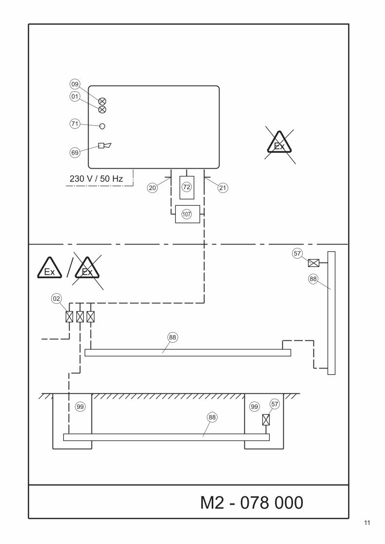
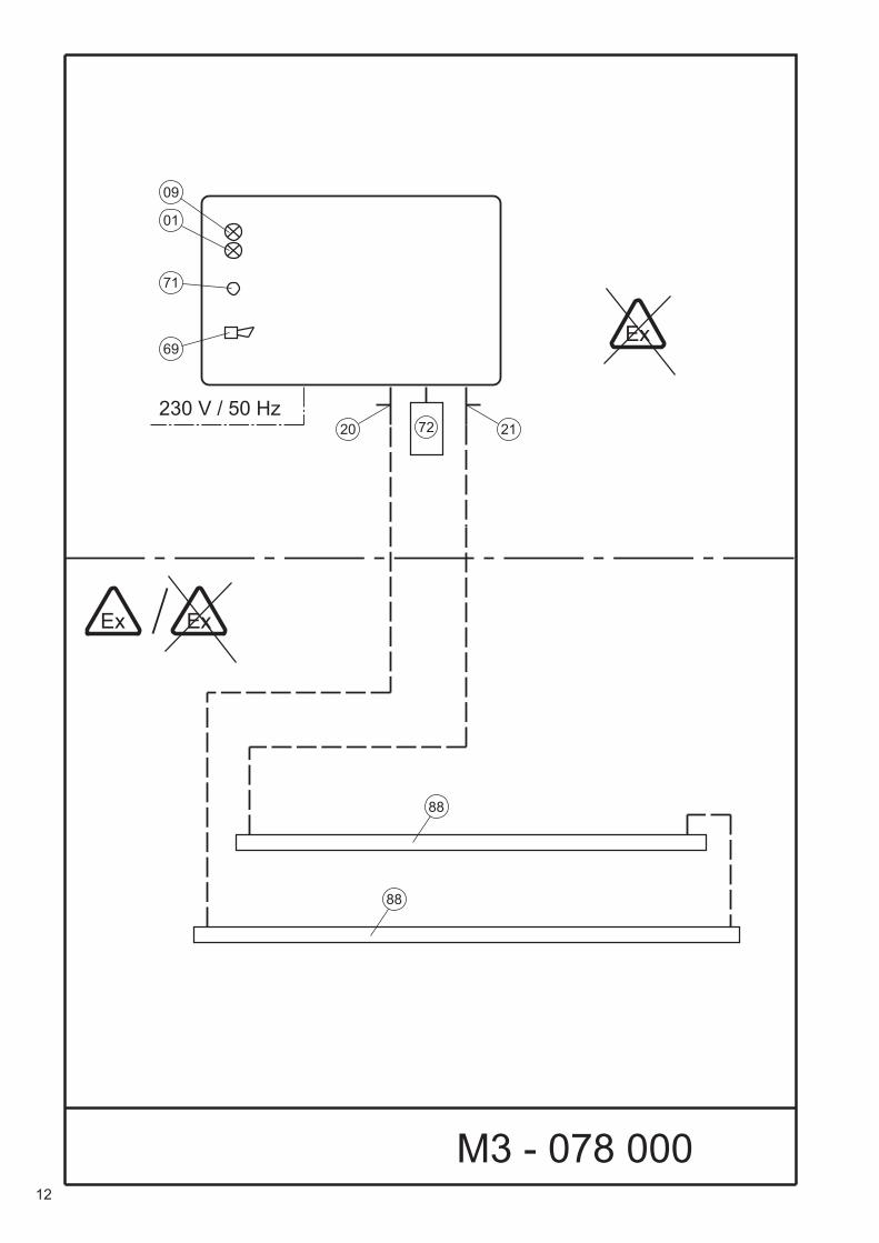
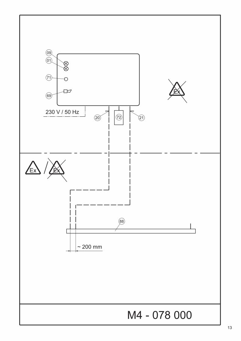
AbbreviationsAbbreviations for the diagrams on the following pages.
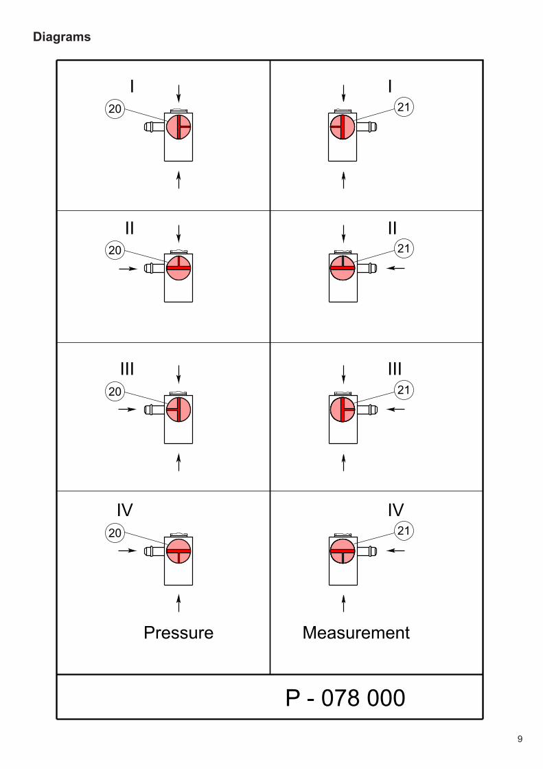
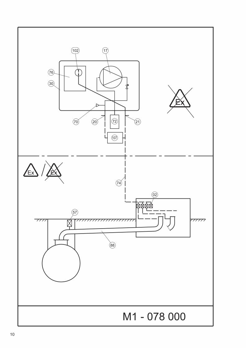
01 Signal lamp – “Alarm” – red02 Shut-off valve09 Signal lamp - “Operation” - green17 Overpressure pump20 Three-way valve in the high-pressure line21 Three-way valve in the measurement line24.1 Fuse22 Venting device30 Housing52 Gauge57 Test valve59 Relay69 Buzzer70 Overpressure valve71 “Audible alarm” button72 Dry filter74 Connecting line76 Main circuit board84 Test container, 1-litre85 Test connection port (gauge)88 Secondary contained pipe / secondary
contained fitting or combination of the two99 Control shaft102 Pressure sensor105 Control unit106 Contacts for serial data transfer107 Pulsation damper
9
Diagrams
II
IIII
IIIIII
IVIV
21
21
21
2120
20
20
20
P - 078 000
Pressure Measurement
10
Ex
17102
72
M1 - 078 000
76
30
212070
ExEx
02
74
57
88
11
57
88
99 99 57
88
88
02
M2 - 078 000
Ex
ExEx
230 V / 50 Hz2120 72
71
69
01
09
12
88
88
M3 - 078 000
Ex
ExEx
230 V / 50 Hz2120 72
71
69
01
09
13
88
M4 - 078 000
Ex
ExEx
230 V / 50 Hz2120 72
71
69
01
09
~ 200 mm
14
SL - 853 600
62 4 53 11 121
AC
DC
105
106102
71 01
69
24.1 59
09
76
17/60
Rp~
15
22
84
85
52
0
Kl. 1,0
P - 115 392
21
21
20
20
90°90°
16
Appendix TD
Technical Data
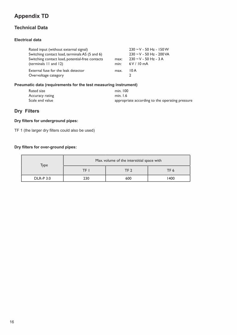
Electrical data
Rated input (without external signal) 230 ~ V - 50 Hz - 150 W Switching contact load, terminals AS (5 and 6) 230 ~ V - 50 Hz - 200 VA Switching contact load, potential-free contacts max: 230 ~ V - 50 Hz - 3 A (terminals 11 and 12) min: 6 V / 10 mA
External fuse for the leak detector max. 10 A Overvoltage category 2
Pneumatic data (requirements for the test measuring instrument) Rated size min. 100 Accuracy rating min. 1.6 Scale end value appropriate according to the operating pressure
Dry Filters
Dry filters for underground pipes:
TF 1 (the larger dry filters could also be used)
Dry filters for over-ground pipes:
TypeMax. volume of the interstitial space with
TF 1 TF 2 TF 6
DLR-P 3.0 230 600 1400
17
Statement on the cross-sections of the connecting lines between leak detector LD-UPP-3 and the interstitial spaces
In the past, the connecting lines between the interstitial spaces and the leak detector have been routed in accordance with TRbF 501 and 502 with the following dimensions:
• For underground or frost-proof routing: clear width of at least 4 mm,• For over-ground routing or routing at risk of frost: clear width of at least 6 mm.
In the future, the European standard for leak detection systems EN 13160 will require
• Connecting lines carrying air to be routed with a clear width of at least 6 mm, and• Connecting lines carrying nitrogen to be routed with a clear width of at least 4 mm.
This requirement in relation to the routing of connecting lines will take effect immediately and continue into the future.
It already has an impact in terms of the approval of leak detectors. This is why a minimum diameter of 6 mm for the connecting line is required in the approval for the leak detector LD-UPP-3.
Installation of the connecting line with a clear width of 4 mm in accordance with TRbF is technically accepted and therefore not something which should be questioned at present. From a technical point of view, there are no objections to using a LD-UPP-3 leak detector on pipes with 4 mm frost-free connecting lines which are routed underground or inside between interstitial spaces and the leak detector.
18
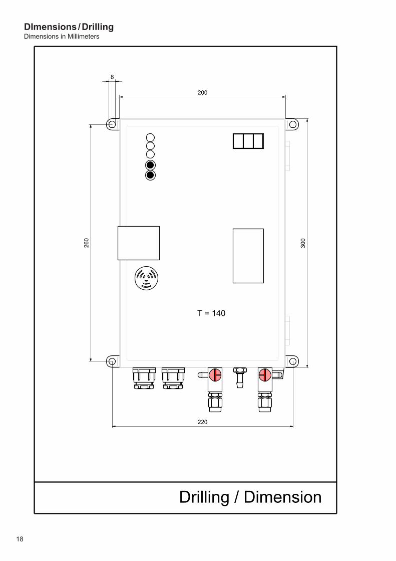
DImensions / DrillingDimensions in Millimeters
Drilling / Dimension
200
300
260
220
T = 140
8
19
Work Sheet AB-820 500Pneumatic connections
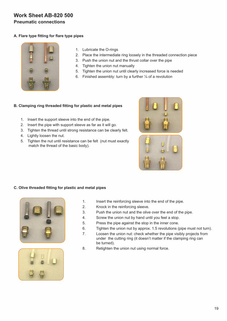
A. Flare type fitting for flare type pipes
1. Lubricate the O-rings2. Place the intermediate ring loosely in the threaded connection piece3. Push the union nut and the thrust collar over the pipe4. Tighten the union nut manually5. Tighten the union nut until clearly increased force is needed6. Finished assembly: turn by a further ¼ of a revolution
B. Clamping ring threaded fitting for plastic and metal pipes
1. Insert the support sleeve into the end of the pipe.2. Insert the pipe with support sleeve as far as it will go.3. Tighten the thread until strong resistance can be clearly felt.4. Lightly loosen the nut.5. Tighten the nut until resistance can be felt (nut must exactly
match the thread of the basic body).
C. Olive threaded fitting for plastic and metal pipes
1. Insert the reinforcing sleeve into the end of the pipe. 2. Knock in the reinforcing sleeve. 3. Push the union nut and the olive over the end of the pipe. 4. Screw the union nut by hand until you feel a stop. 5. Press the pipe against the stop in the inner cone. 6. Tighten the union nut by approx. 1.5 revolutions (pipe must not turn). 7. Loosen the union nut: check whether the pipe visibly projects from
under the cutting ring (it doesn’t matter if the clamping ring can be turned).
8. Retighten the union nut using normal force.
20
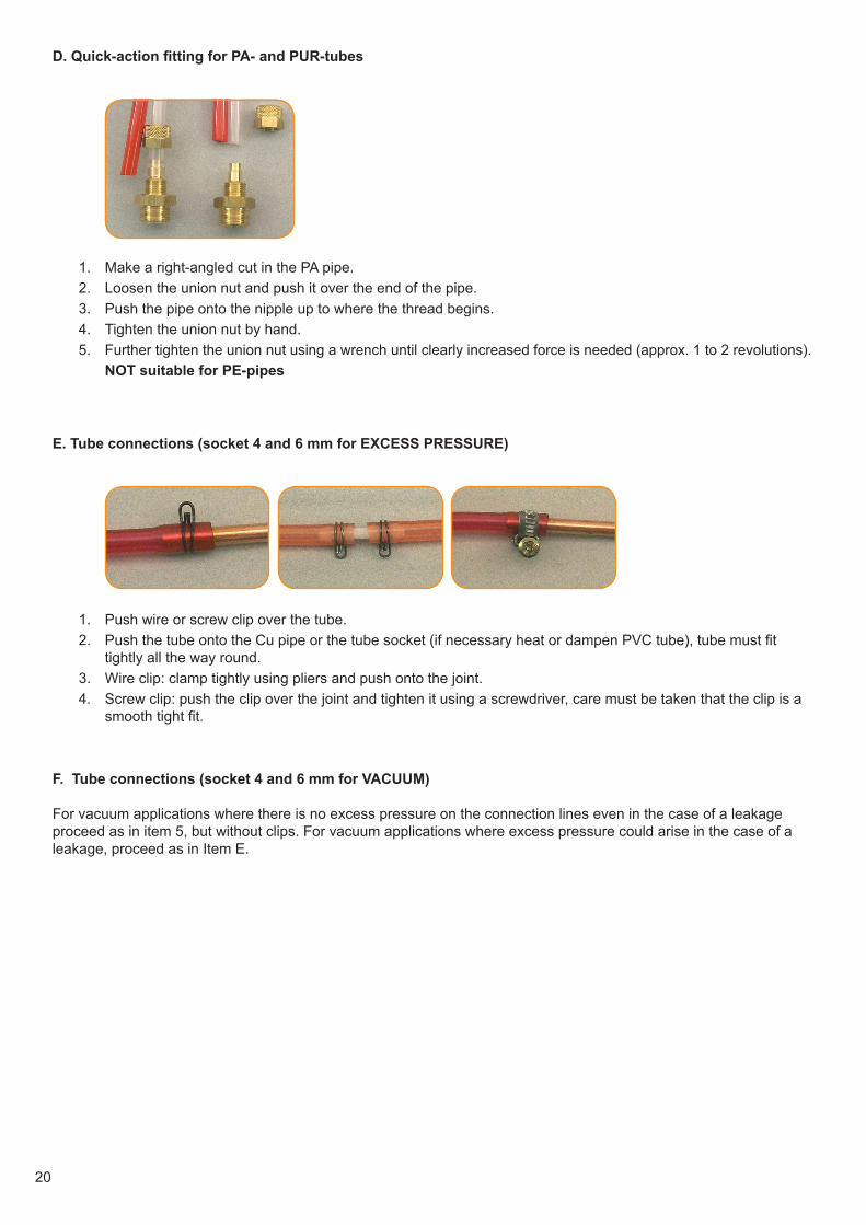
D. Quick-action fitting for PA- and PUR-tubes
1. Make a right-angled cut in the PA pipe.2. Loosen the union nut and push it over the end of the pipe.3. Push the pipe onto the nipple up to where the thread begins.4. Tighten the union nut by hand.5. Further tighten the union nut using a wrench until clearly increased force is needed (approx. 1 to 2 revolutions). NOT suitable for PE-pipes
E. Tube connections (socket 4 and 6 mm for EXCESS PRESSURE)
1. Push wire or screw clip over the tube.2. Push the tube onto the Cu pipe or the tube socket (if necessary heat or dampen PVC tube), tube must fit
tightly all the way round.3. Wire clip: clamp tightly using pliers and push onto the joint.4. Screw clip: push the clip over the joint and tighten it using a screwdriver, care must be taken that the clip is a
smooth tight fit.
F. Tube connections (socket 4 and 6 mm for VACUUM)
For vacuum applications where there is no excess pressure on the connection lines even in the case of a leakage proceed as in item 5, but without clips. For vacuum applications where excess pressure could arise in the case of a leakage, proceed as in Item E.
21
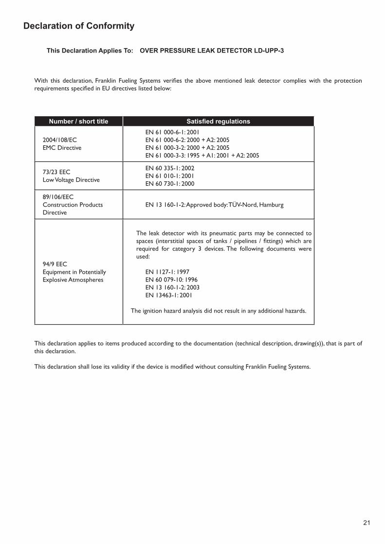
Declaration of Conformity
This Declaration Applies To: OVER PRESSURE LEAK DETECTOR LD-UPP-3
With this declaration, Franklin Fueling Systems verifies the abovementioned leak detector complieswith the protectionrequirementsspecifiedinEUdirectiveslistedbelow:
Number / short title Satisfied regulations
2004/108/ECEMC Directive
EN 61 000-6-1: 2001EN 61 000-6-2: 2000 + A2: 2005EN 61 000-3-2: 2000 + A2: 2005EN 61 000-3-3: 1995 + A1: 2001 + A2: 2005
73/23 EECLow Voltage Directive
EN 60 335-1: 2002EN 61 010-1: 2001EN 60 730-1: 2000
89/106/EECConstruction ProductsDirective
EN13160-1-2:Approvedbody:TÜV-Nord,Hamburg
94/9 EECEquipment in PotentiallyExplosive Atmospheres
The leakdetectorwith itspneumaticpartsmaybeconnectedtospaces (interstitial spacesof tanks /pipelines /fittings)whicharerequired for category 3 devices. The following documents were used:
EN 1127-1: 1997EN 60 079-10: 1996EN 13 160-1-2: 2003EN 13463-1: 2001
The ignition hazard analysis did not result in any additional hazards.
This declaration applies to items produced according to the documentation (technical description, drawing(s)), that is part of this declaration.
ThisdeclarationshallloseitsvalidityifthedeviceismodifiedwithoutconsultingFranklinFuelingSystems.

Franklin Fueling Systems LTD 8 Olympus Close • Whitehouse Industrial Estate Ipswich, Suffolk IP1 5LN • United KingdomTel: +44 1473 243300 • Fax: +44 1473 243301
© FFS 2011 408001013 Rev 1
Related Documents


![Leak Detector [HELIOT 900 Series ] Leak Detector [HELIOT ......Leak Detector Leak Detector ULVAC, Inc. Components Division Overseas Sales in Japan TEL +81-467-89-2261 USA : UL VAC](https://static.cupdf.com/doc/110x72/614653bd8f9ff812542031c4/leak-detector-heliot-900-series-leak-detector-heliot-leak-detector-leak.jpg)