IEEE TRANSACTIONS ON MULTIMEDIA, VOL. 10, NO. 3, APRIL 2008 339 Orthogonal Data Embedding for Binary Images in Morphological Transform Domain- A High-Capacity Approach Huijuan Yang, Alex C. Kot, Fellow, IEEE, and Susanto Rahardja, Senior Member, IEEE Abstract—This paper proposes a data-hiding technique for binary images in morphological transform domain for authen- tication purpose. To achieve blind watermark extraction, it is difficult to use the detail coefficients directly as a location map to determine the data-hiding locations. Hence, we view flipping an edge pixel in binary images as shifting the edge location one pixel horizontally and vertically. Based on this observation, we propose an interlaced morphological binary wavelet transform to track the shifted edges, which thus facilitates blind watermark extraction and incorporation of cryptographic signature. Unlike existing block-based approach, in which the block size is constrained by 3 3 pixels or larger, we process an image in 2 2 pixel blocks. This allows flexibility in tracking the edges and also achieves low computational complexity. The two processing cases that flipping the candidates of one does not affect the flippability conditions of another are employed for orthogonal embedding, which renders more suitable candidates can be identified such that a larger capacity can be achieved. A novel effective Backward-Forward Minimization method is proposed, which considers both back- wardly those neighboring processed embeddable candidates and forwardly those unprocessed flippable candidates that may be affected by flipping the current pixel. In this way, the total visual distortion can be minimized. Experimental results demonstrate the validity of our arguments. Index Terms—Authentication, binary images, data hiding, mor- phological binary wavelet transform, orthogonal embedding. I. INTRODUCTION W ATERMARKING and data-hiding techniques have found wide applications in ownership identification, copy protection, fingerprinting, content authentication and annotation [1], [2]. The design requirements for a data-hiding or watermarking system are different catering for different applications. Recently authentication of digital documents has aroused great interest due to the wide applications in hand- written signatures, digital books, business documents, personal documents, maps, engineering drawings, and so on [3]–[11]. On the other hand, editing an image becomes easier with the pow- erful image editing tools and digital cameras. Authentication to detect tampering and forgery is thus of primary concern. To ensure the authenticity and integrity of these digital documents Manuscript received June 2, 2007; revised November 28, 2007. The Associate Editor coordinating the review of the manuscript and approving it for publication was Dr. W. Gao. H. Yang and A. C. Kot are with School of Electrical and Electronic Engi- neering, Nanyang Technological University,Singapore 639798 (e-mail: ehjyang @ntu.edu.sg; [email protected]). S. Rahardja is with Institute for Infocomm Research ( ), A-STAR, Singa- pore (e-mail: [email protected]). Digital Object Identifier 10.1109/TMM.2008.917404 has increased the confidence level from the user point of view. Most data-hiding techniques for binary images are based on spatial domains, for example, choosing data-hiding locations by employing pairs of contour edge patterns [4], edge pixels [5], [6], visual distortion tables [8], [9] and defining visual quality-preserving rules [10], [11]. However, the capacities of the existing algorithms are not large enough, especially for small images. For example, a capacity as large as 512 bits is required to incorporate a message authentication code such as SHA-2 (e.g., SHA-512). In addition, the existing large capacity algorithm [5] does not have good visual quality of the watermarked image and the computational load is relatively high. Motivated by the above observations, we intend to design a high-capacity data-hiding scheme with low computational complexity and acceptable visual quality. We investigate the data hiding in transform domain to identify the data-hiding locations to avoid the cumbersome pattern-matching process. The goal of authentication is to ensure that a given set of data comes from a legitimate sender and the content integrity is pre- served [12]. Hard authentication rejects any modification made to a multimedia signal [13], whereas soft authentication differ- entiates legitimate processing from malicious tampering [14], [15]. This paper focuses on hard authenticator watermark-based authentication. Specifically, we investigate the problem of data hiding for binary images in morphological transform domain. Generally speaking, data hiding in real-valued transform do- main does not work well for binary images due to the quanti- zation errors introduced in the pre/post-processing [3]. In ad- dition, embedding data using real-valued coefficients requires more memory space. We observe that the morphological binary wavelet transform [16] can be used to track the transitions in bi- nary images by utilizing the detail coefficients. One rather intu- itive idea in employing the morphological binary wavelet trans- form for data hiding is to use the detail coefficients as a loca- tion map to determine the data-hiding locations. However, this makes it difficult to achieve blind watermark extraction due to the fact that once a pixel is flipped, the horizontal, vertical and diagonal detail coefficients will change correspondingly. This problem will be discussed in more detail in Section II. The idea of designing an interlaced transform to identify the embeddable locations is motivated by the fact that some transition informa- tion is lost during the computation of a single transform and there is a need to keep track of transitions between two and three pixels for binary images data hiding. Specifically, we process the images based on 2 2 pixel blocks and combine two dif- ferent processing cases that the flippability conditions of one are 1520-9210/$25.00 © 2008 IEEE

Orthogonal data embedding for binary images in morphological transforms domain a high capacity approach
May 20, 2015
Welcome message from author
This document is posted to help you gain knowledge. Please leave a comment to let me know what you think about it! Share it to your friends and learn new things together.
Transcript
IEEE TRANSACTIONS ON MULTIMEDIA, VOL. 10, NO. 3, APRIL 2008 339
Orthogonal Data Embedding for Binary Images inMorphological Transform Domain-
A High-Capacity ApproachHuijuan Yang, Alex C. Kot, Fellow, IEEE, and Susanto Rahardja, Senior Member, IEEE
Abstract—This paper proposes a data-hiding technique forbinary images in morphological transform domain for authen-tication purpose. To achieve blind watermark extraction, it isdifficult to use the detail coefficients directly as a location map todetermine the data-hiding locations. Hence, we view flipping anedge pixel in binary images as shifting the edge location one pixelhorizontally and vertically. Based on this observation, we proposean interlaced morphological binary wavelet transform to track theshifted edges, which thus facilitates blind watermark extractionand incorporation of cryptographic signature. Unlike existingblock-based approach, in which the block size is constrained by3 3 pixels or larger, we process an image in 2 2 pixel blocks.This allows flexibility in tracking the edges and also achieves lowcomputational complexity. The two processing cases that flippingthe candidates of one does not affect the flippability conditions ofanother are employed for orthogonal embedding, which rendersmore suitable candidates can be identified such that a largercapacity can be achieved. A novel effective Backward-ForwardMinimization method is proposed, which considers both back-wardly those neighboring processed embeddable candidates andforwardly those unprocessed flippable candidates that may beaffected by flipping the current pixel. In this way, the total visualdistortion can be minimized. Experimental results demonstratethe validity of our arguments.
Index Terms—Authentication, binary images, data hiding, mor-phological binary wavelet transform, orthogonal embedding.
I. INTRODUCTION
WATERMARKING and data-hiding techniques havefound wide applications in ownership identification,
copy protection, fingerprinting, content authentication andannotation [1], [2]. The design requirements for a data-hidingor watermarking system are different catering for differentapplications. Recently authentication of digital documents hasaroused great interest due to the wide applications in hand-written signatures, digital books, business documents, personaldocuments, maps, engineering drawings, and so on [3]–[11]. Onthe other hand, editing an image becomes easier with the pow-erful image editing tools and digital cameras. Authenticationto detect tampering and forgery is thus of primary concern. Toensure the authenticity and integrity of these digital documents
Manuscript received June 2, 2007; revised November 28, 2007. The AssociateEditor coordinating the review of the manuscript and approving it for publicationwas Dr. W. Gao.
H. Yang and A. C. Kot are with School of Electrical and Electronic Engi-neering, Nanyang Technological University, Singapore 639798 (e-mail: [email protected]; [email protected]).
S. Rahardja is with Institute for Infocomm Research (I R), A-STAR, Singa-pore (e-mail: [email protected]).
Digital Object Identifier 10.1109/TMM.2008.917404
has increased the confidence level from the user point of view.Most data-hiding techniques for binary images are based onspatial domains, for example, choosing data-hiding locationsby employing pairs of contour edge patterns [4], edge pixels[5], [6], visual distortion tables [8], [9] and defining visualquality-preserving rules [10], [11]. However, the capacities ofthe existing algorithms are not large enough, especially forsmall images. For example, a capacity as large as 512 bits isrequired to incorporate a message authentication code suchas SHA-2 (e.g., SHA-512). In addition, the existing largecapacity algorithm [5] does not have good visual quality of thewatermarked image and the computational load is relativelyhigh. Motivated by the above observations, we intend to designa high-capacity data-hiding scheme with low computationalcomplexity and acceptable visual quality. We investigate thedata hiding in transform domain to identify the data-hidinglocations to avoid the cumbersome pattern-matching process.
The goal of authentication is to ensure that a given set of datacomes from a legitimate sender and the content integrity is pre-served [12]. Hard authentication rejects any modification madeto a multimedia signal [13], whereas soft authentication differ-entiates legitimate processing from malicious tampering [14],[15]. This paper focuses on hard authenticator watermark-basedauthentication. Specifically, we investigate the problem of datahiding for binary images in morphological transform domain.Generally speaking, data hiding in real-valued transform do-main does not work well for binary images due to the quanti-zation errors introduced in the pre/post-processing [3]. In ad-dition, embedding data using real-valued coefficients requiresmore memory space. We observe that the morphological binarywavelet transform [16] can be used to track the transitions in bi-nary images by utilizing the detail coefficients. One rather intu-itive idea in employing the morphological binary wavelet trans-form for data hiding is to use the detail coefficients as a loca-tion map to determine the data-hiding locations. However, thismakes it difficult to achieve blind watermark extraction due tothe fact that once a pixel is flipped, the horizontal, vertical anddiagonal detail coefficients will change correspondingly. Thisproblem will be discussed in more detail in Section II. The ideaof designing an interlaced transform to identify the embeddablelocations is motivated by the fact that some transition informa-tion is lost during the computation of a single transform andthere is a need to keep track of transitions between two and threepixels for binary images data hiding. Specifically, we processthe images based on 2 2 pixel blocks and combine two dif-ferent processing cases that the flippability conditions of one are
1520-9210/$25.00 © 2008 IEEE
340 IEEE TRANSACTIONS ON MULTIMEDIA, VOL. 10, NO. 3, APRIL 2008
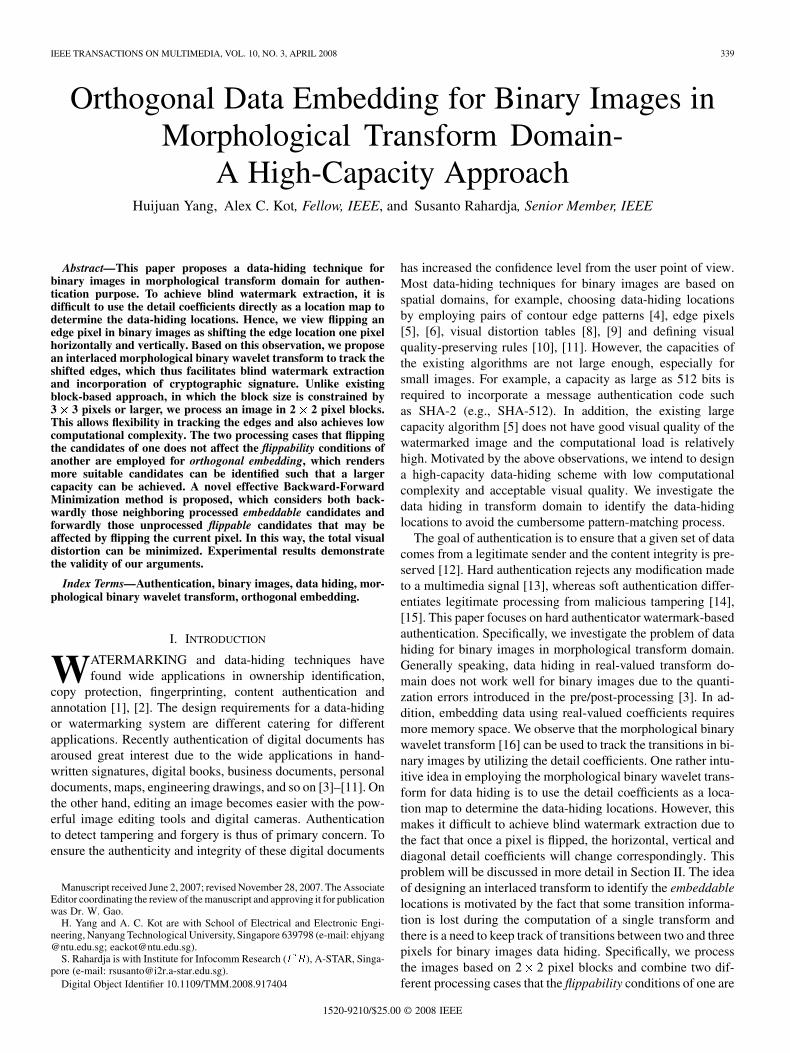
Fig. 1. Illustration of changes in coefficients due to flipping pixels [(a) and (b)]and the “edge shifting” phenomenon [(c) and (d)].
not affected by flipping the candidates of another for data em-bedding, namely “orthogonal embedding”. This addresses theproblem of the capacity decrease due to the un-embeddability ofthe block boundaries, sharing rows and columns in block-basedapproaches [11]. As a result, significant gains in capacity canbe achieved, which also improves the efficiency of utilizing theflippable pixels. Implementing the transforms by the “ExclusiveOR (XOR)” operation addresses the quantization error issue ina DCT-based approach [7]. The major advantages of the pro-posed scheme lie in its larger capacity (e.g., compared with [4],[5], [8], [9], [11]), better visual quality (e.g., compared with[5]–[7]) and lower computational complexity (e.g., comparedwith [5], [8], [11]). In addition, unlike [11], our present schemedoes not suffer the capacity decrease and computational loadincrease in order to incorporate the cryptographic signature forauthentication.
This paper is organized as follows. A brief review on existing1-D morphological binary wavelet transform (MBWT), ourproposed extension to 2-D MBWT and the interlaced MBWT(IMBWT) are presented in Section II. The authenticationscheme employing IMBWT and elimination of the redundancyin IMBWT by the proposed prediction and update lifting MBWT(PUMBWT) are discussed in Section III. Experimental resultsand discussions are presented in Sections IV and V concludesthe paper.
II. INTERLACED MORPHOLOGICAL TRANSFORM
One intuitive idea in utilizing MBWT for data hiding is to usethe detail coefficients as a location map to determine the data-hiding locations, since these coefficients contain the edge infor-mation in horizontal, vertical and diagonal directions. However,flipping a pixel involves changing the coefficients, as illustratedin Fig. 1(a) and (b). It can be seen that the same edges used todetermine the data-hiding locations cannot be found in the wa-termarked image [e.g., Fig. 1(b)]. We observe that flipping anedge pixel in binary images is equivalent to shifting the edgelocation horizontally one pixel [e.g., vertical edge shifting fromFig. 1(c) to (d)] and vertically one pixel [e.g., horizontal edgeshifting from Fig. 1(c) to (d)]. In the figure, “1” and “0” rep-resent the black and white pixels, respectively. To this end, wedesign an IMBWT to keep track of the shifted edges to achieveblind watermark extraction.
In this section, we start the discussion with signal analysisand synthesis which is similar to [16]. A brief review on the1-D signal decomposition given in [16] is also included. Basedon this, we further extend the decomposition scheme to 2-Dsignal and subsequently propose an interlaced transform for thedata-hiding application.
A. Morphological Binary Wavelet Transform
Consider a family of signal space and detail space atlevel . The 1-D wavelet decomposition scheme comprises ofone signal analysis operator and one detail analysis operator
. In addition, it also consists of one signal synthesis operatorand one detail synthesis operator . Here “ ” indicates
that the corresponding operator maps a signal to a higher level,towards the direction of reducing the information. Whereas “ ”indicates that the operator maps a signal to a lower level, towardsthe direction of restoring the information. The signal analysisoperator maps a signal, , from level
to for the scaled signal , .The detail analysis operator maps a signalfrom level to for the detail signal ,
. On the other hand, the signal synthesis operatormaps a signal from level back to level to
obtain an approximation of , i.e., . The detailsynthesis operator maps a detail signal backto level so as to obtain the detail signal . Thesignal at level is reconstructed by
(1)
As discussed in [16], [17], perfect reconstruction of the originalsignal is possible if the operators satisfy
(2)
(3)
(4)
where “ ” and “ ” represent the identity and zero operators, re-spectively. Note that is a set of biorthog-onal filter operators if the conditions in (2)–(4) are satisfied.For the morphological analysis and synthesis scheme discussedin this paper, the bi-orthogonality is formulated in the operatorterms. For simplicity, we shall delete the index in the corre-sponding analysis and synthesis operators due to only one stepdecomposition between and is considered. Let“ ” denote the “Exclusive OR (XOR)” operation. The signalsat level by applying the analysis operators for a 1-D signalare given by
(5)
(6)
where and are the coarse and detail signals obtained atlevel , respectively; denotes the index of the signal at level
and for a 1-D signal of size . Thedetail signal contains 1 s at each transition from 0 to 1 orvice versa in signal . The synthesis operators are given by
(7)
(8)
The signal at level is reconstructed by
(9)
(10)
YANG et al.: ORTHOGONAL DATA EMBEDDING FOR BINARY IMAGES IN MORPHOLOGICAL TRANSFORM DOMAIN-A HIGH-CAPACITY APPROACH 341
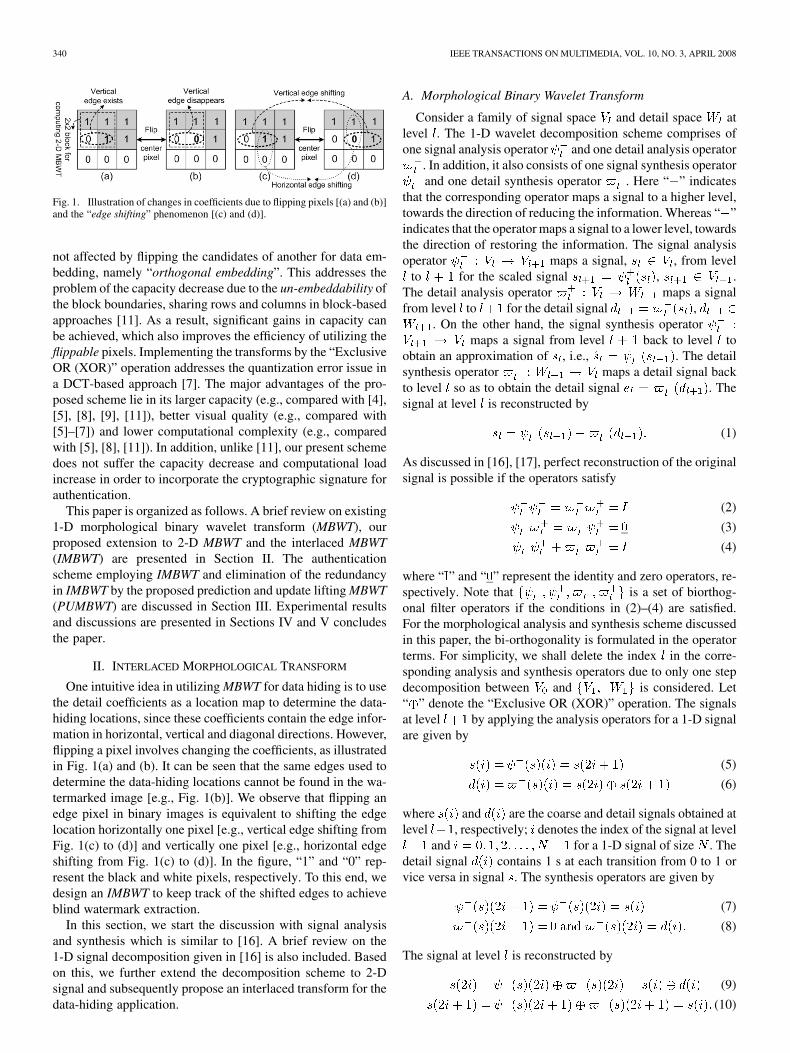
Fig. 2. Designation of samples in a 2� 2 block.
B. 2-D and Interlaced Morphological Binary WaveletTransform
We now extend the 1-D wavelet decomposition scheme [16]to a 2-D signal by defining a non-separable 2-D transform. Let
and represent the indices of the signal at level , whereand for a 2-D
coarse signal of size . Designation of the samples ina 2 2 block is shown in Fig. 2, where denotes thesignal (“0” or “1”) located at row and column at level .To define a 2-D transform, one sample in a 2 2 block can besub-sampled as the coarse signal. The horizontal, vertical anddiagonal detail signals are derived from the difference betweenthe sub-sampled sample and its vertical, horizontal and diagonal(including diagonal and anti-diagonal) neighbors. The resultanttransformed signal remains binary while the coarse and detailsignals will each be 1/4 the size of the original signal. Let theoperators for the coarse signal, horizontal, vertical, and diagonaldetail signals be , , and , respectively, wherethe superscript “ ” denotes “even-even”. The obtained trans-form is named the even-even transform since it is operated on a2 2 block starting from the even-even coordinates. The coarsesignal, vertical, horizontal and diagonal detail signals at level
are obtained by applying the analysis operators to yield
(11)
(12)
(13)
(14)
where and. The synthesis operators of a 2-D wavelet transform are
given by
(15)
(16)
(17)
(18)
(19)
Finally, the signal at level can be reconstructed by
(20)
(21)
(22)
(23)
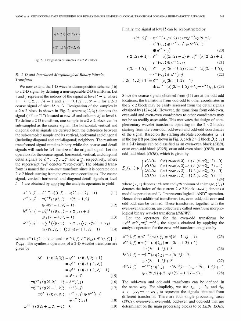
Since the coarse signals obtained from (11) are at the odd-oddlocations, the transitions from odd-odd to other coordinates inthe 2 2 block may be easily assessed from the detail signalsobtained by (12)–(14). However, the transitions from odd-even,even-odd and even-even coordinates to other coordinates maynot be so readily assessable. This motivates the design of com-plementary wavelet transforms operating on the 2 2 blocksstarting from the even-odd, odd-even and odd-odd coordinatesof the signal. Based on the starting absolute coordinatesin the top left position shown in Fig. 3, each 2 2 blockin a 2-D image can be classified as an even-even block (EEB),or an even-odd block (EOB), or an odd-even block (OEB), or anodd-odd block (OOB), which is given by
forforforfor
(24)where denotes row and column of an image,denotes the index of the current 2 2 block, denotes amodulo operation and “ ” represents logical “AND” operation.Hence, three additional transforms, i.e., even-odd, odd-even andodd-odd, can be defined. These transforms, together with theeven-even transform, are collectively called interlaced morpho-logical binary wavelet transform (IMBWT).
Let the operators for the even-odd transforms be, the signals obtained by applying the
analysis operators for the even-odd transform are given by
(25)
(26)
(27)
(28)
The odd-even and odd-odd transforms can be defined inthe same way. For simplicity, we use , , and ,
, to represent the signals obtained fromdifferent transforms. There are four single processing cases(SPCs): even-even, even-odd, odd-even and odd-odd that aredeterminant on the main processing blocks to be EEBs, EOBs,
342 IEEE TRANSACTIONS ON MULTIMEDIA, VOL. 10, NO. 3, APRIL 2008
Fig. 3. Four different 2� 2 blocks in a 3� 3 block of a binary image.
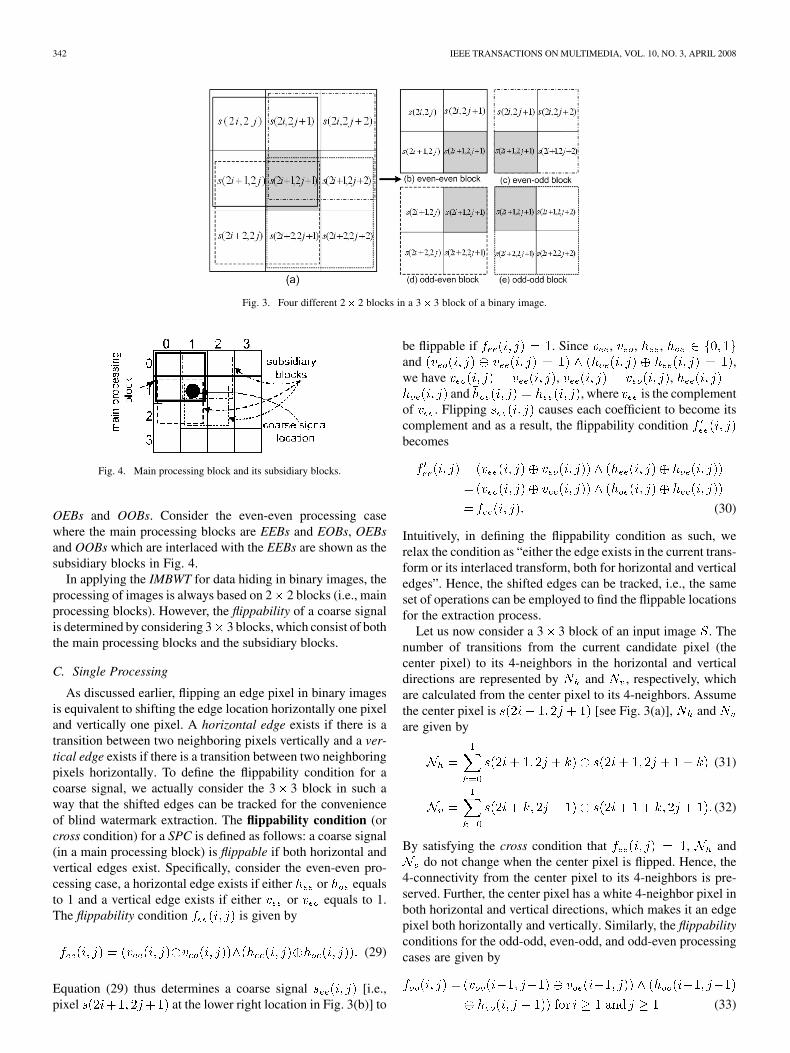
Fig. 4. Main processing block and its subsidiary blocks.
OEBs and OOBs. Consider the even-even processing casewhere the main processing blocks are EEBs and EOBs, OEBsand OOBs which are interlaced with the EEBs are shown as thesubsidiary blocks in Fig. 4.
In applying the IMBWT for data hiding in binary images, theprocessing of images is always based on 2 2 blocks (i.e., mainprocessing blocks). However, the flippability of a coarse signalis determined by considering 3 3 blocks, which consist of boththe main processing blocks and the subsidiary blocks.
C. Single Processing
As discussed earlier, flipping an edge pixel in binary imagesis equivalent to shifting the edge location horizontally one pixeland vertically one pixel. A horizontal edge exists if there is atransition between two neighboring pixels vertically and a ver-tical edge exists if there is a transition between two neighboringpixels horizontally. To define the flippability condition for acoarse signal, we actually consider the 3 3 block in such away that the shifted edges can be tracked for the convenienceof blind watermark extraction. The flippability condition (orcross condition) for a SPC is defined as follows: a coarse signal(in a main processing block) is flippable if both horizontal andvertical edges exist. Specifically, consider the even-even pro-cessing case, a horizontal edge exists if either or equalsto 1 and a vertical edge exists if either or equals to 1.The flippability condition is given by
(29)
Equation (29) thus determines a coarse signal [i.e.,pixel at the lower right location in Fig. 3(b)] to
be flippable if . Since , , ,and ,we have , ,
and , where is the complementof . Flipping causes each coefficient to become itscomplement and as a result, the flippability conditionbecomes
(30)
Intuitively, in defining the flippability condition as such, werelax the condition as “either the edge exists in the current trans-form or its interlaced transform, both for horizontal and verticaledges”. Hence, the shifted edges can be tracked, i.e., the sameset of operations can be employed to find the flippable locationsfor the extraction process.
Let us now consider a 3 3 block of an input image . Thenumber of transitions from the current candidate pixel (thecenter pixel) to its 4-neighbors in the horizontal and verticaldirections are represented by and , respectively, whichare calculated from the center pixel to its 4-neighbors. Assumethe center pixel is [see Fig. 3(a)], andare given by
(31)
(32)
By satisfying the cross condition that , anddo not change when the center pixel is flipped. Hence, the
4-connectivity from the center pixel to its 4-neighbors is pre-served. Further, the center pixel has a white 4-neighbor pixel inboth horizontal and vertical directions, which makes it an edgepixel both horizontally and vertically. Similarly, the flippabilityconditions for the odd-odd, even-odd, and odd-even processingcases are given by
(33)
YANG et al.: ORTHOGONAL DATA EMBEDDING FOR BINARY IMAGES IN MORPHOLOGICAL TRANSFORM DOMAIN-A HIGH-CAPACITY APPROACH 343
(34)
(35)
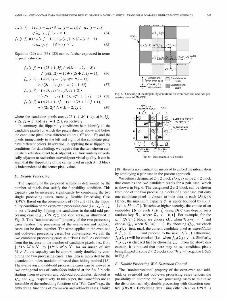
Equation (29) and (33)–(35) can be further expressed in termsof pixel values as
(36)
(37)
(38)
(39)
where the candidate pixels are: , ,and , respectively.
In summary, the flippability conditions help identify all thecandidate pixels for which the pixels directly above and belowthe candidate pixel have different colors (“0” and “1”) and thepixels immediately to the left and right of the candidate pixelhave different colors. In addition, in applying these flippabilityconditions for data hiding, we require that the two chosen can-didate pixels should not be 4-adjacent, i.e., horizontally or verti-cally adjacent to each other to avoid poor visual quality. It can beseen that the flippability of the center pixel in each 3 3 blockis independent of the center pixel value.
D. Double Processing
The capacity of the proposed scheme is determined by thenumber of pixels that satisfy the flippability condition. Thiscapacity can be increased significantly by combining the twosingle processing cases, namely, Double Processing Case(DPC). Based on the observations of (36) and (37), the flippa-bility condition of the even-even processing case (i.e., )is not affected by flipping the candidates in the odd-odd pro-cessing case (e.g., ) and vice versa, as illustrated inFig. 5. This “nonintersection” property of the two processingcases renders the processing of the even-even and odd-oddcases can be done together. The same applies to the even-oddand odd-even processing cases. For convenience, we call thetwo combined processing cases as a “Pair Case”. As evidencedfrom the increase in the number of candidate pixels, i.e., from
to for an image of size, the capacity can be approximately doubled by com-
bining the two processing cases. This idea is motivated by thequantization index modulation based data-hiding method [18].The even-even and odd-odd processing cases can be viewed astwo orthogonal sets of embedders indexed at the 2 2 blocksstarting from even-even and odd-odd coordinates, denoted as
and , respectively. In this paper, the embedders are anensemble of the embedding functions of a “Pair Case”, e.g., theembedding functions of even-even and odd-odd cases. Unlike
Fig. 5. Checking of the flippability conditions for even-even and odd-odd pro-cessing cases of IMBWT.
Fig. 6. Designated 2� 2 blocks.
[18], there is no quantization involved to embed the informationby employing a pair case in the present approach.
We define a designated 2 2 block as the 2 2 blockthat contains the two candidate pixels for a pair case, whichis shown in Fig. 6. The designated 2 2 block can be chosenfrom one of the two processing blocks of a pair case, but onlyone candidate pixel is chosen to hide data in each .Hence, the maximum capacity is upper bounded by
. To achieve higher security, the choice of anembedder in each using DPC can depend on arandom key , where . For example, for the
block, we choose when andchoose when . By choosing , we check
first, mark the current candidate pixel as embeddableif and proceed to the next . Otherwise,
will be checked (i.e., when ). Similarly,is checked first by choosing . From the above dis-
cussion, it is noticed that there may be two candidate pixelsbeing flipped in some 2 2 blocks (not ), e.g., the OOBsin Fig. 6.
E. Double Processing With Distortion Control
The “nonintersection” property of the even-even and odd-odd, or even-odd and odd-even processing cases renders thepossibility to combine the two processing cases to minimizethe distortion, namely, double processing with distortion con-trol (DPDC). Embedding data using either DPC or DPDC is
344 IEEE TRANSACTIONS ON MULTIMEDIA, VOL. 10, NO. 3, APRIL 2008
described as orthogonal embedding. Consider processing theusing DPDC, an index (which is subsequently
used to choose the corresponding embedder to determine theembeddable location) is chosen such that the distortion betweenthe original pattern and watermarked patternwith respect to embedder is minimized by
(40)
where and represents the distortion mea-sures such as the visual distortion tables [8], [9] and other mea-sures [10], . To compare the vi-sual distortion caused by employing different embedders, thelist of patterns that satisfy the flippability conditions should beranked first. Minimization by only considering the two candi-dates determined by the two embedders in each maycause the increase in distortion to the neighboring flippable can-didates, which ultimately may consume the reduced distortiongained by minimization. To minimize the overall distortion, weconsider backwardly those neighboring processed embeddablecandidates (e.g., C, D and E of EEBs in Fig. 6 which are af-fected by flipping A in OOB) and consider forwardly those un-processed flippable candidates (e.g., F, G and H of OOBs inFig. 6 which are affected by flipping B in EEB), namely, Back-ward-Forward Minimization (BFM). Let be the embedderin the neighboring 2 2 blocks to be considered, hereonly takes one value from ; is an indicatorfunction to represent whether is chosen (“1”) or not (“0”)in the processed neighboring 2 2 blocks for backward min-imization, or flippable (“1”) or not (“0”) in the unprocessedneighboring 2 2 blocks for forward minimization. Further, let
and , and and be the watermarkedand original patterns, before and after flipping the candidate inthe by choosing , respectively. The accumu-lated change in distortion in the neighboring 2 2 blocksbecause of choosing is given by (41), as shown at the bottomof the page, whereand for backward andforward minimization, respectively. is subsequently em-ployed to update the distortion generated by choosing embedder
, (40) thus becomes
(42)Noticeably, an embedder in DPC is chosen based on a random
key, whereas it is chosen to minimize the distortion for eachflipping in DPDC. As illustrated in Fig. 6, by using DPC orDPDC, flipping a candidate pixel (coarse signal) of the sub-sidiary blocks (e.g., pixel “A” in the OOB, here
) results in changes in the corresponding diagonal detail coeff-cient of the main processing blocks (e.g., EEB).
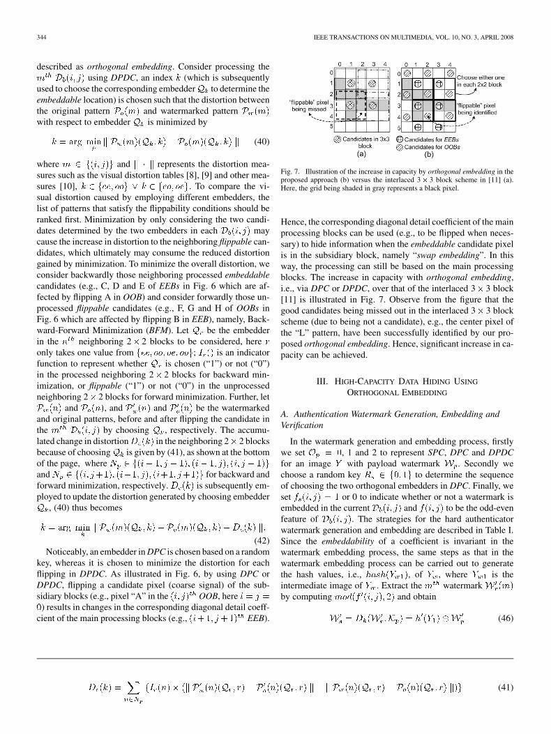
Fig. 7. Illustration of the increase in capacity by orthogonal embedding in theproposed approach (b) versus the interlaced 3� 3 block scheme in [11] (a).Here, the grid being shaded in gray represents a black pixel.
Hence, the corresponding diagonal detail coefficient of the mainprocessing blocks can be used (e.g., to be flipped when neces-sary) to hide information when the embeddable candidate pixelis in the subsidiary block, namely “swap embedding”. In thisway, the processing can still be based on the main processingblocks. The increase in capacity with orthogonal embedding,i.e., via DPC or DPDC, over that of the interlaced 3 3 block[11] is illustrated in Fig. 7. Observe from the figure that thegood candidates being missed out in the interlaced 3 3 blockscheme (due to being not a candidate), e.g., the center pixel ofthe “L” pattern, have been successfully identified by our pro-posed orthogonal embedding. Hence, significant increase in ca-pacity can be achieved.
III. HIGH-CAPACITY DATA HIDING USING
ORTHOGONAL EMBEDDING
A. Authentication Watermark Generation, Embedding andVerification
In the watermark generation and embedding process, firstlywe set , 1 and 2 to represent SPC, DPC and DPDCfor an image with payload watermark . Secondly wechoose a random key to determine the sequenceof choosing the two orthogonal embedders in DPC. Finally, weset or 0 to indicate whether or not a watermark isembedded in the current and to be the odd-evenfeature of . The strategies for the hard authenticatorwatermark generation and embedding are described in Table I.Since the embeddability of a coefficient is invariant in thewatermark embedding process, the same steps as that in thewatermark embedding process can be carried out to generatethe hash values, i.e., , of , where is theintermediate image of . Extract the watermarkby computing and obtain
(46)
(41)
YANG et al.: ORTHOGONAL DATA EMBEDDING FOR BINARY IMAGES IN MORPHOLOGICAL TRANSFORM DOMAIN-A HIGH-CAPACITY APPROACH 345
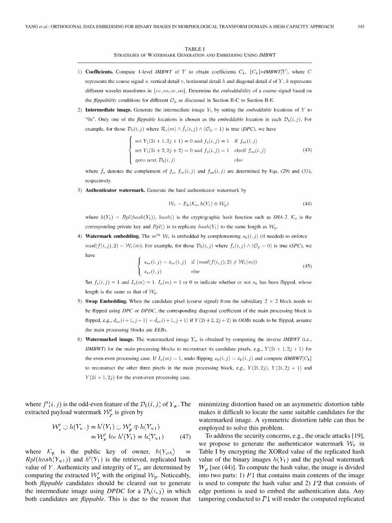
TABLE ISTRATEGIES OF WATERMARK GENERATION AND EMBEDDING USING IMBWT
where is the odd-even feature of the of . Theextracted payload watermark is given by
(47)
where is the public key of owner,and is the retrieved, replicated hash
value of . Authenticity and integrity of are determined bycomparing the extracted with the original . Noticeably,both flippable candidates should be cleared out to generatethe intermediate image using DPDC for a in whichboth candidates are flippable. This is due to the reason that
minimizing distortion based on an asymmetric distortion tablemakes it difficult to locate the same suitable candidates for thewatermarked image. A symmetric distortion table can thus beemployed to solve this problem.
To address the security concerns, e.g., the oracle attacks [19],we propose to generate the authenticator watermark inTable I by encrypting the XORed value of the replicated hashvalue of the binary images and the payload watermark
[see (44)]. To compute the hash value, the image is dividedinto two parts: 1) that contains main contents of the imageis used to compute the hash value and 2) that consists ofedge portions is used to embed the authentication data. Anytampering conducted to will render the computed replicated
346 IEEE TRANSACTIONS ON MULTIMEDIA, VOL. 10, NO. 3, APRIL 2008
hash value of the watermarked image vary significantlyfrom the retrieved replicated hash value of the original image
, due to the sensitivity of the hash function to changes.Hence, reveal the tampering. On the other hand, any tamperingconducted to will results in changes in either or
or both of them. Changes in eventually lead tochange [see (47)]. Thus, the tampering can be easily detectedupon comparison of with . Employing the secure hashfunction helps detect any changes made to the watermarkeddocument.
B. Redundancy Elimination
Let’s look at the flippability condition for the odd-oddprocessing case given in (33), in which four coefficients,i.e., , , and
, need to be computed and six “XOR” and onelogical “AND” operations are required. The redundancy liesin that the center pixel has been XORed four times in thecoefficients calculation, which can be eliminated when theflippability condition is expressed in pixel values [see (37)].Motivated by this observation, we design a transform called theprediction and update lifting MBWT (PUMBWT) to eliminatethe redundancy in IMBWT.
1) Forward and Inverse PUMBWT for 1-D Signal: Letand be the prediction and update operators. The predictionand update lifting scheme for the even processing case consistsof the following steps.
• Split the signal into odd-indexed and even-indexed sets, de-noted as and , respectively,where .
• Predict the odd sets from the even sets, using the predictionerror, , to update the currentprediction, i.e.,
, where .• The coarse approximation of the signal is the even sets of
samples, denoted by which is updated by the predic-tion error , i.e., .
• Reverse the same prediction and update steps, the originalsignal can be perfectly reconstructed, i.e.,
and, where .
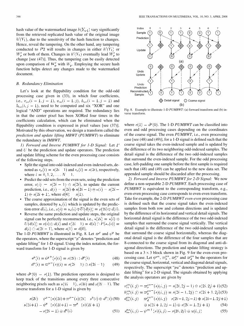
The 1-D PUMBWT is illustrated in Fig. 8. Let and bethe operators, where the superscript “ ” denotes “prediction andupdate lifting” for 1-D signal. Using the index notation, the for-ward transform for 1-D signal is given by
(48)
(49)
where . The prediction operation is designed tokeep track of the transitions among every three consecutiveneighboring pixels such as , and . Theinverse transform for a 1-D signal is given by
(50)
(51)
Fig. 8. Example to illustrate 1-D PUMBWT: (a) forward transform and (b) in-verse transform.
where . The 1-D PUMBWT can be classified intoeven and odd processing cases depending on the coordinatesof the coarse signal. The even PUMBWT, i.e., even processingcase [see (48) and (49)], for a 1-D signal is defined such that thecoarse signal takes the even-indexed sample and is updated bythe difference of its two neighboring odd-indexed samples. Thedetail signal is the difference of the two odd-indexed samplesthat surround the even-indexed sample. For the odd processingcase, left-padding one sample before the first sample is requiredsuch that (48) and (49) can be applied to the new data set. Theappended sample should be discarded after the processing.
2) Forward and Inverse PUMBWT for 2-D Signal: We nowdefine a non-separable 2-D PUMBWT. Each processing case ofPUMBWT is equivalent to the corresponding transform, e.g.,even-even processing case corresponds to even-even transform.Take for example, the 2-D PUMBWT even-even processing caseis defined such that the coarse signal takes the even-indexedsamples from both row and column directions and is updatedby the difference of its horizontal and vertical detail signals. Thehorizontal detail signal is the difference of the two odd-indexedsamples that surround the coarse signal vertically. The verticaldetail signal is the difference of the two odd-indexed samplesthat surround the coarse signal horizontally, whereas the diag-onal detail signal is the difference of the four samples that are8-connected to the coarse signal from its diagonal and anti-di-agonal directions. The prediction and update lifting strategy isbased on a 3 3 block shown in Fig. 9 for the even-even pro-cessing case. Let , , and be the operators forthe coarse signal, horizontal, vertical and diagonal detail signals,respectively. The superscript “ ” denotes “prediction and up-date lifting” for a 2-D signal. The signals obtained by applyingthe analysis operators are given by
(52)
(53)
(54)
(55)
YANG et al.: ORTHOGONAL DATA EMBEDDING FOR BINARY IMAGES IN MORPHOLOGICAL TRANSFORM DOMAIN-A HIGH-CAPACITY APPROACH 347
Fig. 9. Designations of samples in a 3� 3 block.
where the indices of the signal are ,; and
the subscript “ ” represents the “even-even” transform. Theboundary conditions for (52)–(55) are given by (56), as shownat the bottom of the page. The signals at level are reconstructedby applying the synthesis operators to yield
(57)
(58)
(59)
(60)
The boundary conditions for (57)–(60) are given by
when
when
when
(61)
The same set of equations [i.e., (52)–(55)] can be appliedto compute odd-even, even-odd and odd-odd PUMBWT by ap-pending one row, one column and both one row and one column
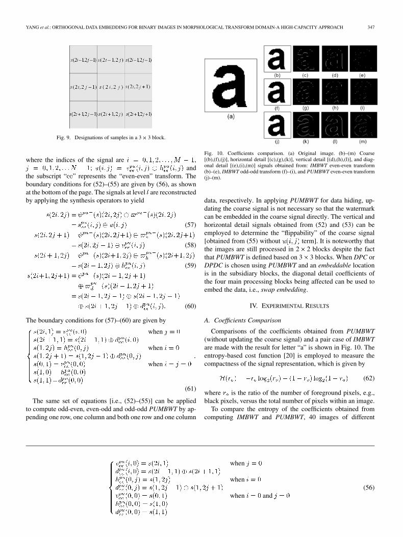
Fig. 10. Coefficients comparison. (a) Original image. (b)–(m) Coarse[(b),(f),(j)], horizontal detail [(c),(g),(k)], vertical detail [(d),(h),(l)], and diag-onal detail [(e),(i),(m)] signals obtained from: IMBWT even-even transform(b)–(e), IMBWT odd-odd transform (f)–(i), and PUMBWT even-even transform(j)–(m).
data, respectively. In applying PUMBWT for data hiding, up-dating the coarse signal is not necessary so that the watermarkcan be embedded in the coarse signal directly. The vertical andhorizontal detail signals obtained from (52) and (53) can beemployed to determine the “flippability” of the coarse signal[obtained from (55) without term]. It is noteworthy thatthe images are still processed in 2 2 blocks despite the factthat PUMBWT is defined based on 3 3 blocks. When DPC orDPDC is chosen using PUMBWT and an embeddable locationis in the subsidiary blocks, the diagonal detail coefficients ofthe four main processing blocks being affected can be used toembed the data, i.e., swap embedding.
IV. EXPERIMENTAL RESULTS
A. Coefficients Comparison
Comparisons of the coefficients obtained from PUMBWT(without updating the coarse signal) and a pair case of IMBWTare made with the result for letter “a” is shown in Fig. 10. Theentropy-based cost function [20] is employed to measure thecompactness of the signal representation, which is given by
(62)
where is the ratio of the number of foreground pixels, e.g.,black pixels, versus the total number of pixels within an image.
To compare the entropy of the coefficients obtained fromcomputing IMBWT and PUMBWT, 40 images of different
when
when
when and(56)
348 IEEE TRANSACTIONS ON MULTIMEDIA, VOL. 10, NO. 3, APRIL 2008
TABLE IIENTROPY COMPARISON OF WAVELET COEFFICIENTS
types and resolutions are used with the results of 15 imageshown in Table II. It is not difficult to observe from Fig. 10 andTable II that the coefficients of a single transform of IMBWTand PUMBWT give small entropy values, indicating the largediscrepancy between the number of foreground and backgroundpixels. Hence, a more compact signal representation can beachieved using both transforms. However, the entropy valueof the detail coefficients obtained from computing PUMBWTis much larger than that obtained from computing a singletransform of IMBWT, e.g., even-even transform. This demon-strates that more transition information can be obtained usingPUMBWT or the interlaced transform.
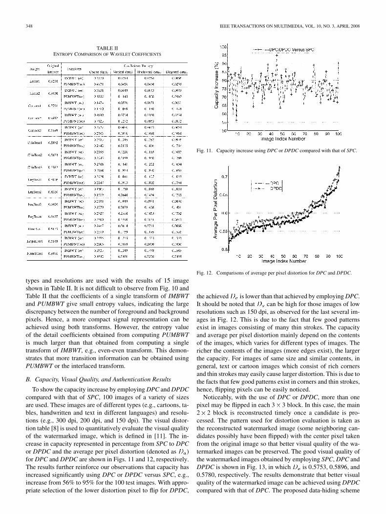
B. Capacity, Visual Quality, and Authentication Results
To show the capacity increase by employing DPC and DPDCcompared with that of SPC, 100 images of a variety of sizesare used. These images are of different types (e.g., cartoons, ta-bles, handwritten and text in different languages) and resolu-tions (e.g., 300 dpi, 200 dpi, and 150 dpi). The visual distor-tion table [8] is used to quantitatively evaluate the visual qualityof the watermarked image, which is defined in [11]. The in-crease in capacity represented in percentage from SPC to DPCor DPDC and the average per pixel distortion (denoted as )for DPC and DPDC are shown in Figs. 11 and 12, respectively.The results further reinforce our observations that capacity hasincreased significantly using DPC or DPDC versus SPC, e.g.,increase from 56% to 95% for the 100 test images. With appro-priate selection of the lower distortion pixel to flip for DPDC,
Fig. 11. Capacity increase using DPC or DPDC compared with that of SPC.
Fig. 12. Comparisons of average per pixel distortion for DPC and DPDC.
the achieved is lower than that achieved by employing DPC.It should be noted that can be high for those images of lowresolutions such as 150 dpi, as observed for the last several im-ages in Fig. 12. This is due to the fact that few good patternsexist in images consisting of many thin strokes. The capacityand average per pixel distortion mainly depend on the contentsof the images, which varies for different types of images. Thericher the contents of the images (more edges exist), the largerthe capacity. For images of same size and similar contents, ingeneral, text or cartoon images which consist of rich cornersand thin strokes may easily cause larger distortion. This is due tothe facts that few good patterns exist in corners and thin strokes,hence, flipping pixels can be easily noticed.
Noticeably, with the use of DPC or DPDC, more than onepixel may be flipped in each 3 3 block. In this case, the main2 2 block is reconstructed timely once a candidate is pro-cessed. The pattern used for distortion evaluation is taken asthe reconstructed watermarked image (some neighboring can-didates possibly have been flipped) with the center pixel takenfrom the original image so that better visual quality of the wa-termarked images can be preserved. The good visual quality ofthe watermarked images obtained by employing SPC, DPC andDPDC is shown in Fig. 13, in which is 0.5753, 0.5896, and0.5780, respectively. The results demonstrate that better visualquality of the watermarked image can be achieved using DPDCcompared with that of DPC. The proposed data-hiding scheme
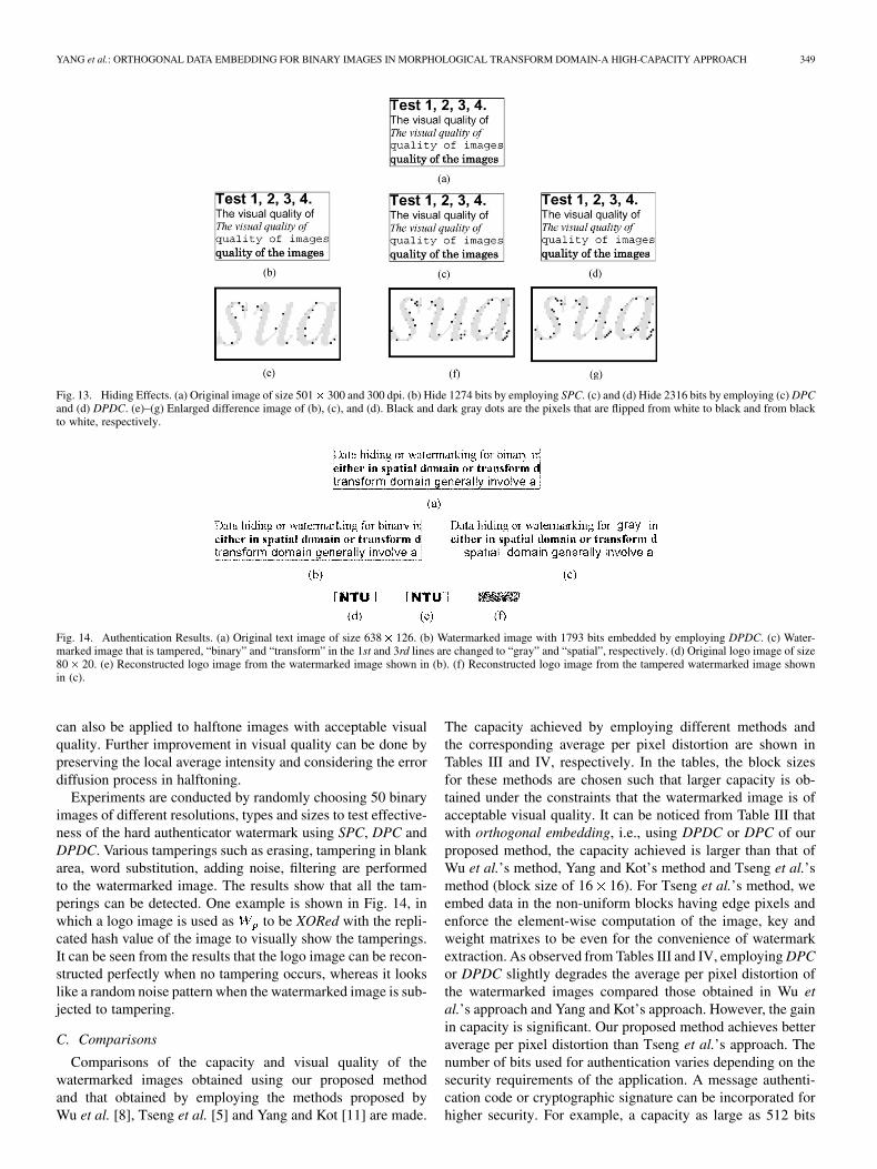
YANG et al.: ORTHOGONAL DATA EMBEDDING FOR BINARY IMAGES IN MORPHOLOGICAL TRANSFORM DOMAIN-A HIGH-CAPACITY APPROACH 349
Fig. 13. Hiding Effects. (a) Original image of size 501� 300 and 300 dpi. (b) Hide 1274 bits by employing SPC. (c) and (d) Hide 2316 bits by employing (c) DPCand (d) DPDC. (e)–(g) Enlarged difference image of (b), (c), and (d). Black and dark gray dots are the pixels that are flipped from white to black and from blackto white, respectively.
Fig. 14. Authentication Results. (a) Original text image of size 638� 126. (b) Watermarked image with 1793 bits embedded by employing DPDC. (c) Water-marked image that is tampered, “binary” and “transform” in the 1st and 3rd lines are changed to “gray” and “spatial”, respectively. (d) Original logo image of size80� 20. (e) Reconstructed logo image from the watermarked image shown in (b). (f) Reconstructed logo image from the tampered watermarked image shownin (c).
can also be applied to halftone images with acceptable visualquality. Further improvement in visual quality can be done bypreserving the local average intensity and considering the errordiffusion process in halftoning.
Experiments are conducted by randomly choosing 50 binaryimages of different resolutions, types and sizes to test effective-ness of the hard authenticator watermark using SPC, DPC andDPDC. Various tamperings such as erasing, tampering in blankarea, word substitution, adding noise, filtering are performedto the watermarked image. The results show that all the tam-perings can be detected. One example is shown in Fig. 14, inwhich a logo image is used as to be XORed with the repli-cated hash value of the image to visually show the tamperings.It can be seen from the results that the logo image can be recon-structed perfectly when no tampering occurs, whereas it lookslike a random noise pattern when the watermarked image is sub-jected to tampering.
C. Comparisons
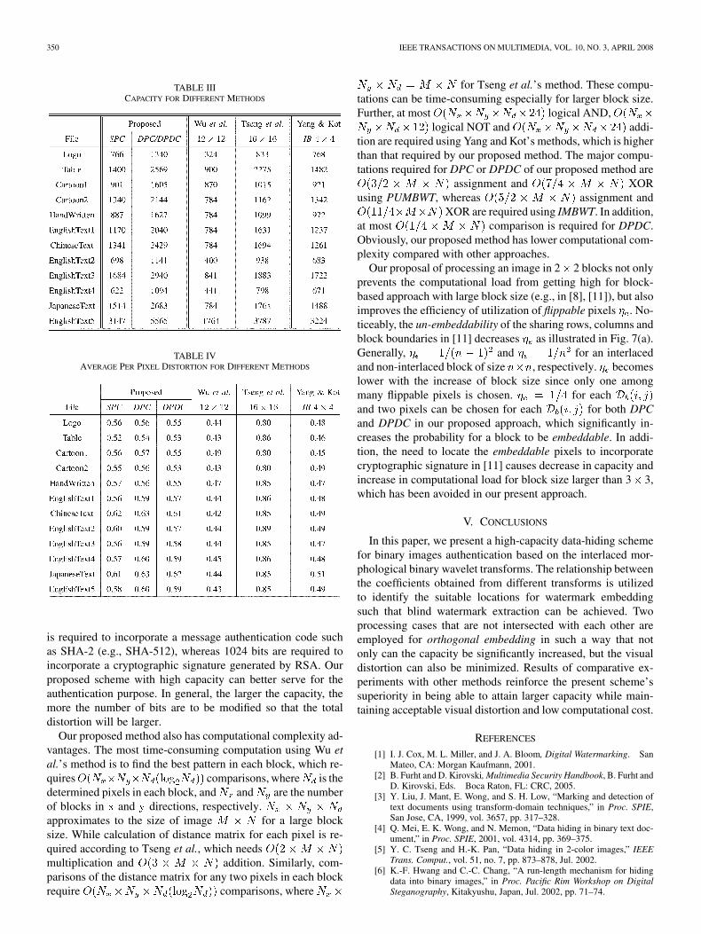
Comparisons of the capacity and visual quality of thewatermarked images obtained using our proposed methodand that obtained by employing the methods proposed byWu et al. [8], Tseng et al. [5] and Yang and Kot [11] are made.
The capacity achieved by employing different methods andthe corresponding average per pixel distortion are shown inTables III and IV, respectively. In the tables, the block sizesfor these methods are chosen such that larger capacity is ob-tained under the constraints that the watermarked image is ofacceptable visual quality. It can be noticed from Table III thatwith orthogonal embedding, i.e., using DPDC or DPC of ourproposed method, the capacity achieved is larger than that ofWu et al.’s method, Yang and Kot’s method and Tseng et al.’smethod (block size of 16 16). For Tseng et al.’s method, weembed data in the non-uniform blocks having edge pixels andenforce the element-wise computation of the image, key andweight matrixes to be even for the convenience of watermarkextraction. As observed from Tables III and IV, employing DPCor DPDC slightly degrades the average per pixel distortion ofthe watermarked images compared those obtained in Wu etal.’s approach and Yang and Kot’s approach. However, the gainin capacity is significant. Our proposed method achieves betteraverage per pixel distortion than Tseng et al.’s approach. Thenumber of bits used for authentication varies depending on thesecurity requirements of the application. A message authenti-cation code or cryptographic signature can be incorporated forhigher security. For example, a capacity as large as 512 bits
350 IEEE TRANSACTIONS ON MULTIMEDIA, VOL. 10, NO. 3, APRIL 2008
TABLE IIICAPACITY FOR DIFFERENT METHODS
TABLE IVAVERAGE PER PIXEL DISTORTION FOR DIFFERENT METHODS
is required to incorporate a message authentication code suchas SHA-2 (e.g., SHA-512), whereas 1024 bits are required toincorporate a cryptographic signature generated by RSA. Ourproposed scheme with high capacity can better serve for theauthentication purpose. In general, the larger the capacity, themore the number of bits are to be modified so that the totaldistortion will be larger.
Our proposed method also has computational complexity ad-vantages. The most time-consuming computation using Wu etal.’s method is to find the best pattern in each block, which re-quires comparisons, where is thedetermined pixels in each block, and and are the numberof blocks in and directions, respectively.approximates to the size of image for a large blocksize. While calculation of distance matrix for each pixel is re-quired according to Tseng et al., which needsmultiplication and addition. Similarly, com-parisons of the distance matrix for any two pixels in each blockrequire comparisons, where
for Tseng et al.’s method. These compu-tations can be time-consuming especially for larger block size.Further, at most logical AND,
logical NOT and addi-tion are required using Yang and Kot’s methods, which is higherthan that required by our proposed method. The major compu-tations required for DPC or DPDC of our proposed method are
assignment and XORusing PUMBWT, whereas assignment and
XOR are required using IMBWT. In addition,at most comparison is required for DPDC.Obviously, our proposed method has lower computational com-plexity compared with other approaches.
Our proposal of processing an image in 2 2 blocks not onlyprevents the computational load from getting high for block-based approach with large block size (e.g., in [8], [11]), but alsoimproves the efficiency of utilization of flippable pixels . No-ticeably, the un-embeddability of the sharing rows, columns andblock boundaries in [11] decreases as illustrated in Fig. 7(a).Generally, and for an interlacedand non-interlaced block of size , respectively. becomeslower with the increase of block size since only one amongmany flippable pixels is chosen. for eachand two pixels can be chosen for each for both DPCand DPDC in our proposed approach, which significantly in-creases the probability for a block to be embeddable. In addi-tion, the need to locate the embeddable pixels to incorporatecryptographic signature in [11] causes decrease in capacity andincrease in computational load for block size larger than 3 3,which has been avoided in our present approach.
V. CONCLUSIONS
In this paper, we present a high-capacity data-hiding schemefor binary images authentication based on the interlaced mor-phological binary wavelet transforms. The relationship betweenthe coefficients obtained from different transforms is utilizedto identify the suitable locations for watermark embeddingsuch that blind watermark extraction can be achieved. Twoprocessing cases that are not intersected with each other areemployed for orthogonal embedding in such a way that notonly can the capacity be significantly increased, but the visualdistortion can also be minimized. Results of comparative ex-periments with other methods reinforce the present scheme’ssuperiority in being able to attain larger capacity while main-taining acceptable visual distortion and low computational cost.
REFERENCES
[1] I. J. Cox, M. L. Miller, and J. A. Bloom, Digital Watermarking. SanMateo, CA: Morgan Kaufmann, 2001.
[2] B. Furht and D. Kirovski, Multimedia Security Handbook, B. Furht andD. Kirovski, Eds. Boca Raton, FL: CRC, 2005.
[3] Y. Liu, J. Mant, E. Wong, and S. H. Low, “Marking and detection oftext documents using transform-domain techniques,” in Proc. SPIE,San Jose, CA, 1999, vol. 3657, pp. 317–328.
[4] Q. Mei, E. K. Wong, and N. Memon, “Data hiding in binary text doc-ument,” in Proc. SPIE, 2001, vol. 4314, pp. 369–375.
[5] Y. C. Tseng and H.-K. Pan, “Data hiding in 2-color images,” IEEETrans. Comput., vol. 51, no. 7, pp. 873–878, Jul. 2002.
[6] K.-F. Hwang and C.-C. Chang, “A run-length mechanism for hidingdata into binary images,” in Proc. Pacific Rim Workshop on DigitalSteganography, Kitakyushu, Japan, Jul. 2002, pp. 71–74.
YANG et al.: ORTHOGONAL DATA EMBEDDING FOR BINARY IMAGES IN MORPHOLOGICAL TRANSFORM DOMAIN-A HIGH-CAPACITY APPROACH 351
[7] H. Lu, X. Shi, Y. Q. Shi, A. C. Kot, and L. Chen, “Watermarkembedding in DC components of DCT for binary images,” in Proc.,IEEE Workshop on Multimedia Signal Processing, Dec. 9–11, 2002,pp. 300–303.
[8] M. Wu and B. Liu, “Data hiding in binary images for authenticationand annotation,” IEEE Trans. Multimedia, vol. 6, no. 4, pp. 528–538,Aug. 2004.
[9] H. Y. Kim and R. L. de Queiroz, “Alteration-locating authenticationwatermarking for binary images,” in Proc. Int. Workshop Digital Wa-termarking, 2004, pp. 125–136.
[10] H. Lu, A. C. Kot, and Y. Q. Shi, “Distance-reciprocal distortion mea-sure for binary document images,” IEEE Signal Process. Lett., vol. 11,no. 2, pp. 228–231, Feb. 2004.
[11] H. Yang and A. C. Kot, “Pattern-based date hiding for binary imagesauthentication by connectivity-preserving,” IEEE Trans. Multimedia,vol. 9, no. 3, pp. 475–486, Apr. 2007.
[12] B. B. Zhu, M. D. Swanson, and A. H. Tewfik, “When seeing isn’t be-lieving,” IEEE Signal Process. Mag., pp. 40–49, Mar. 2004.
[13] P. W. Wong and N. Memon, “Secret and public key image water-marking schemes for image authentication and ownership verification,”IEEE Trans. Image Process., vol. 10, no. 10, pp. 1593–1601, Oct. 2001.
[14] D. Kundur and D. Hatzinakos, “Digital watermarking for telltaletamper proofing and authentication,” Proc. IEEE, vol. 87, no. 7, pp.1167–1179, Jul. 1999.
[15] C.-Y. Lin and S.-F. Chang, “A robust image authentication methoddistinguishing JPEG compression from malicious manipulation,” IEEETrans. Circuits Syste. Video Technol., vol. 11, no. 2, pp. 153–168, Feb.2001.
[16] H. J. A. M. Heijmans and J. Goutsias, “Nonlinear multiresolution signaldecomposition schemes-part II: Morphological wavelets,” IEEE Trans.Image Process., vol. 9, no. 11, pp. 1897–1913, Nov. 2000.
[17] W. Sweldens, “The lifting scheme: A construction of second generationwavelets,” SIAM J. Math. Anal., vol. 29, pp. 511–546, 1998.
[18] B. Chen and G. W. Wornell, “Quantization index modulation: Aclass of provably good methods for digital watermarking and infor-mation embedding,” IEEE Trans. Inform. Theory, vol. 47, no. 4, pp.1423–1443, May 2001.
[19] J. Wu, B. B. Zhu, S. Li, and F. Lin, “Efficient oracle attacks on yeung-mintzer and variant authentication schemes,” in Proc. IEEE Int. Conf.Multimedia and Expo., Jun. 27–30, 2004, vol. 2 , pp. 931–934.
[20] M. D. Swanson and A. H. Tewfik, “A binary wavelet decompositionof binary images,” IEEE Trans. Image Process., vol. 5, no. 12, pp.1637–1650, Dec. 1996.
Huijuan Yang received the B.Sc degree from JilinUniversity, Changchun, China, and the M. Eng.degree from Nanyang Technological University,Singapore, where she is currently pursuing the Ph.Ddegree.
From March 2001 to November 2002, she wasa Security Software Engineer with CrimsonLogicPte. Ltd., Singapore. She has been a ResearchAssociate with School of Electrical and ElectronicEngineering, Nanyang Technological University,since 2002. Her research interests include digital
multimedia processing, authentication, and information security. She hasinvented/co-invented two Singapore patents (granted) on watermarking andcontrol of document distribution and has three pending U.S. patents.
Alex C. Kot (F’06) has been with Nanyang Tech-nological University, Singapore, since 1991. Heheaded the Division of Information Engineering atthe School of Electrical and Electronic Engineeringfor eight years and is currently a Professor andthe Associate Chair/Vice Dean (Research) for theSchool of Electrical and Electronic Engineering. Hehas published extensively in the areas of signal pro-cessing for communication, biometrics, data-hidingand authentication.
Dr. Kot served as Associate Editor for the IEEETRANSACTIONS ON SIGNAL PROCESSING, the IEEE TRANSACTIONS ON CIRCUITS
AND SYSTEMS FOR VIDEO TECHNOLOGY, and the IEEE TRANSACTIONS ON
CIRCUITS AND SYSTEMS II. He is currently an Associate Editor for theEURASIP Journal of Applied Signal Processing, the IEEE TRANSACTIONS ON
CIRCUITS AND SYSTEMS I, and the IEEE TRANSACTIONS ON MULTIMEDIA. Heis a member of the Visual Signal Processing and Communication TechnicalCommittee and the Image and Multidimensional Signal Processing TechnicalCommittee. He was the General Co-Chair for the 2004 IEEE International Con-ference on Image Processing (ICIP) and has served as an IEEE DistinguishedLecturer. He is a Fellow of IES.
Susanto Rahardja (SM’03) received the B.Eng. de-gree from the National University of Singapore andthe M.Eng. and Ph.D. degrees from Nanyang Techno-logical University (NTU), Singapore, all in electricaland electronic engineering.
He is the Director of the Personal 3D Enter-tainment System program and Head of the SignalProcessing Department at the Institute for Info-comm Research (I R), Singapore. He is also anAssociate Professor at the School of Electrical andElectronic Engineering, NTU. His research interests
are in audio/video signal processing, spread-spectrum and multi-user detectiontechniques for CDMA applications, digital signal processing algorithms and im-plementations, and logic synthesis, of which he has more than 200 publicationsin internationally refereed journals and conferences. Since 2002, he has activelyparticipated in the international ISO/IEC JTC1/SC29/WG11 Moving PictureExpert Group (MPEG) where he contributed to the MPEG-4 Scalable LosslessSystem (SLS) which is incorporated into ISO/IEC 14496–3:2005/Amd.3:2006.He also contributed technology to the MPEG-4 Audio Lossless System (ALS)which is now incorporated into ISO/IEC 14496–3:2005/Amd.2:2006.
Dr. Rahardja was awarded the Standards Council Merit Award by SPRINGSingapore in 2006 in recognition for his contributions to the national standard-ization program. For his leadership and technical contribution to advancementof digital audio signal processing and its adoption to the MPEG, he was awardedthe National Technology Award in 2007. He was also the recipient of the IEEHartree Premium Award in 2002 and the prestigious Tan Kah Kee YoungInventors’ Gold award in the Open Category, for his contributions on scalableto lossless audio compression technology, in 2003. He has served on severalboards and advisory and technical committees in various IEEE- and SPIE-related professional activities in the areas of multimedia. He is an electedmember of the Technical Committee of the Visual Signal Processing andCommunications, Circuits and Systems for Communications and MultimediaSystems and Applications of the IEEE Circuits and Systems Society. Heis currently serving as Associate Editor for the IEEE TRANSACTIONS ON
AUDIO, SPEECH AND LANGUAGE PROCESSING and the IEEE TRANSACTIONS
ON MULTIMEDIA, as well as the Journal of Visual Communication and ImageRepresentation.
Related Documents


![Flexible Orthogonal Neighborhood Preserving … learning projection (LPP)[He and Niyogi, 2004] and neighborhood preserving embedding (NPE) [He et al., 2005] are the representative](https://static.cupdf.com/doc/110x72/5ad7b9f27f8b9a9d5c8c7797/flexible-orthogonal-neighborhood-preserving-learning-projection-lpphe-and.jpg)