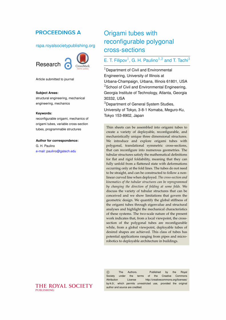
rspa.royalsocietypublishing.org Research Article submitted to journal Subject Areas: structural engineering, mechanical engineering, mechanics Keywords: reconfigurable origami, mechanics of origami tubes, variable cross-section tubes, programmable structures Author for correspondence: G. H. Paulino e-mail: [email protected] Origami tubes with reconfigurable polygonal cross-sections E. T. Filipov 1 , G. H. Paulino 1,2 and T. Tachi 3 1 Department of Civil and Environmental Engineering, University of Illinois at Urbana-Champaign, Urbana, Illinois 61801, USA 2 School of Civil and Environmental Engineering, Georgia Institute of Technology, Atlanta, Georgia 30332, USA 3 Department of General System Studies, University of Tokyo, 3-8-1 Komaba, Meguro-Ku, Tokyo 153-8902, Japan Thin sheets can be assembled into origami tubes to create a variety of deployable, reconfigurable, and mechanistically unique three dimensional structures. We introduce and explore origami tubes with polygonal, translational symmetric cross-sections, that can reconfigure into numerous geometries. The tubular structures satisfy the mathematical definitions for flat and rigid foldability, meaning that they can fully unfold from a flattened state with deformations occurring only at the fold lines. The tubes do not need to be straight, and can be constructed to follow a non- linear curved line when deployed. The cross-section and kinematics of the tubular structures can be reprogrammed by changing the direction of folding at some folds. We discuss the variety of tubular structures that can be conceived and we show limitations that govern the geometric design. We quantify the global stiffness of the origami tubes through eigenvalue and structural analyses and highlight the mechanical characteristics of these systems. The two-scale nature of the present work indicates that, from a local viewpoint, the cross- section of the polygonal tubes are reconfigurable while, from a global viewpoint, deployable tubes of desired shapes are achieved. This class of tubes has potential applications ranging from pipes and micro- robotics to deployable architecture in buildings. c The Authors. Published by the Royal Society under the terms of the Creative Commons Attribution License http://creativecommons.org/licenses/ by/4.0/, which permits unrestricted use, provided the original author and source are credited.

Welcome message from author
This document is posted to help you gain knowledge. Please leave a comment to let me know what you think about it! Share it to your friends and learn new things together.
Transcript
rspa.royalsocietypublishing.org
Research
Article submitted to journal
Subject Areas:
structural engineering, mechanical
engineering, mechanics
Keywords:
reconfigurable origami, mechanics of
origami tubes, variable cross-section
tubes, programmable structures
Author for correspondence:
G. H. Paulino
e-mail: [email protected]
Origami tubes withreconfigurable polygonalcross-sectionsE. T. Filipov1, G. H. Paulino1,2 and T. Tachi3
1Department of Civil and EnvironmentalEngineering, University of Illinois atUrbana-Champaign, Urbana, Illinois 61801, USA2School of Civil and Environmental Engineering,Georgia Institute of Technology, Atlanta, Georgia30332, USA3Department of General System Studies,University of Tokyo, 3-8-1 Komaba, Meguro-Ku,Tokyo 153-8902, Japan
Thin sheets can be assembled into origami tubes tocreate a variety of deployable, reconfigurable, andmechanistically unique three dimensional structures.We introduce and explore origami tubes withpolygonal, translational symmetric cross-sections,that can reconfigure into numerous geometries. Thetubular structures satisfy the mathematical definitionsfor flat and rigid foldability, meaning that they canfully unfold from a flattened state with deformationsoccurring only at the fold lines. The tubes do not needto be straight, and can be constructed to follow a non-linear curved line when deployed. The cross-section andkinematics of the tubular structures can be reprogrammedby changing the direction of folding at some folds. Wediscuss the variety of tubular structures that can beconceived and we show limitations that govern thegeometric design. We quantify the global stiffness ofthe origami tubes through eigenvalue and structuralanalyses and highlight the mechanical characteristicsof these systems. The two-scale nature of the presentwork indicates that, from a local viewpoint, the cross-section of the polygonal tubes are reconfigurablewhile, from a global viewpoint, deployable tubes ofdesired shapes are achieved. This class of tubes haspotential applications ranging from pipes and micro-robotics to deployable architecture in buildings.
c© The Authors. Published by the RoyalSociety under the terms of the Creative CommonsAttribution License http://creativecommons.org/licenses/by/4.0/, which permits unrestricted use, provided the originalauthor and source are credited.
2
rspa.royalsocietypublishing.orgP
rocR
Soc
A0000000
...............................................................
1. IntroductionHistorically, origami has gained popularity in science and engineering because a compactlystowed or flat system can be folded into a transformable 3D structure with increased functionality.Proposed applications in the smaller length scales include biomedical devices [1], and microrobotic assembly [2]. In medium sizes, origami techniques have been used in creating compliantmechanisms [3], actuators [4], toys, and educational tools [5]. Large origami structures couldbe constructed for aerospace [6] and architectural applications [7]. The applications seem to beendless.
More recently, innovation with origami has pivoted on its capability to create programmableand re-programmable systems that can change shape, function, and mechanical properties.For example Hawkes et al. [8] created a sheet with pre-defined fold lines that can reshapeautonomously into different three dimensional structures. Marras et al. [9] showed that DNA canbe folded to create nano-scale mechanisms with programmable mechanical function. Origamimetamaterials that can be reconfigured, and whose mechanical properties can be tuned andtailored have also become a popular subject of study [10–13].
Thin walled origami tubes have been created by folding thin sheets, but they typicallydiffer from the fundamental definitions of origami. In particular: entire origami tubes are notdevelopable, meaning they cannot be created from a continuous flat sheet; and they require gluingor some other connectivity for creating the complete tube. Despite the higher complexity ofmanufacturing, origami tubes greatly extend the functionality of engineered thin sheet structures.For example, they can be be used as deployable stents in biomedicine [14], as inflatable structuralbooms for space structures [15,16], or as actuators and bellows [4,17,18]. Origami tubes have a self-constraining geometry that makes them suitable for energy absorption devices [19–22]. Stackingand coupling of origami tubes into more complex geometries can lead to stiffening of the systemand enhanced mechanical characteristics [11,13,23,24].
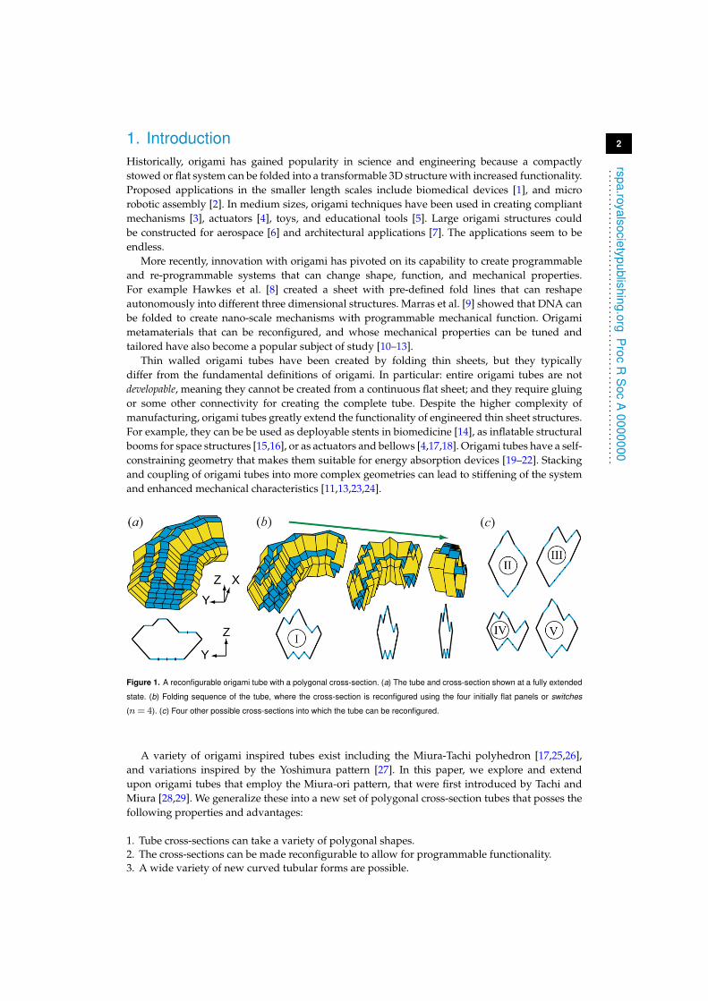
Figure 1. A reconfigurable origami tube with a polygonal cross-section. (a) The tube and cross-section shown at a fully extended
state. (b) Folding sequence of the tube, where the cross-section is reconfigured using the four initially flat panels or switches
(n= 4). (c) Four other possible cross-sections into which the tube can be reconfigured.
A variety of origami inspired tubes exist including the Miura-Tachi polyhedron [17,25,26],and variations inspired by the Yoshimura pattern [27]. In this paper, we explore and extendupon origami tubes that employ the Miura-ori pattern, that were first introduced by Tachi andMiura [28,29]. We generalize these into a new set of polygonal cross-section tubes that posses thefollowing properties and advantages:
1. Tube cross-sections can take a variety of polygonal shapes.2. The cross-sections can be made reconfigurable to allow for programmable functionality.3. A wide variety of new curved tubular forms are possible.
3
rspa.ro yalsocietypublishing.orgP
rocR
Soc
A0000000
...............................................................
4. The tubes are compatible and can be coupled into a variety of assemblages.5. The mechanical properties of the tubes can be tuned through reconfiguration.6. Out-of-plane compression stiffness is enhanced similar to corrugated pipe systems.7. The perimeter of the tubes is continuous, allowing for deployment by inflation and for the
potential capability to carry liquids and gases.8. Based on idealized zero-thickness kinematics, the tubes are flat foldable meaning that they can
fold down to a completely flat state allowing for compact stowage.9. These systems are rigid foldable, meaning the origami can fold and unfold with deformation
concentrated only along the fold lines (creases), while the panels (facets) remain flat. Thiscapability could allow the structures to be constructed with panels of finite thickness [30–32],and to fold in a controlled motion.
Properties 1, 2, 3, 5, and 6 are possible with the new polygonal tube definitions presented herein.Some of the advantages are motivated by figure 1 that shows a curved tube that can fold in avariety of different cross-sections. The versatility, mechanical characteristics and reconfigurabilityof theses tubes could result in numerous applications as pipelines, architectural structures, roboticcomponents, bellows, metamaterials, and other reprogrammable systems.
The paper is organized as follows: Section 2 introduces the cross-sections, and Section 3provides the full three dimensional definition for admissible polygonal tubes. The systemkinematics and reconfigurable characteristics of different tubes are discussed in Section 4. InSection 5 we extend the tubular definitions to cellular assemblages that can also be reconfigured.In Section 6 we discuss the elastic modelling and explore the mechanical properties of the tubesthrough eigenvalue and structural analyses. Tubes with circular cross-sections are investigated inSection 7, and Section 8 provides a discussion and concluding remarks. Appendix A explainsfolding characteristics of the idealized tubes assuming zero-thickness, Appendix B gives ananalytical comparison between smooth pipes and origami tubes, and Appendix C gives anoutlook for practical implementations and future extensions of the proposed systems.
2. Cross-section definitions for polygonal tubesThe popular Miura-ori pattern has inspired the development of rigid foldable origami tubesdiscussed in several recent articles [13,23–25,28,29,33]. The cross-sections of these tubes aresymmetric, with the most fundamental tube consisting of two equal symmetric Miura-ori stripsplaced opposite from each other. More advanced cross-sections follow isotropic, anisotropic,or star shaped cylindrical variations [25,28,29]. In this work, we go beyond the previous tubevariations and introduce a translational symmetry method to create a variety of polygonal shapedtubes. The basic cross-section variations for the polygonal tubes are defined in the Y − Z axis, asdemonstrated by figure 2. For our definition, we divide the geometry of the cross-section into anupper (U ) and a lower (L) section. The names of these two sections are only representative andtheir location may in fact be side by side as shown later in figures 3 and 4. The two opposingsections of the tube have to be continuous and can be composed of m≥ 2 edge groups. The edgegroups are identified by a unique slope angle θ, and denoted by a lower-case letter (a, b, c ...). Theslope angle is taken clockwise from the Z axis of the cross-section, and has the admissible rangeof −180◦ < θ < 180◦. Each edge group on the upper section can be composed of p≥ 1 edges, andthe corresponding lower edge group can be composed of q≥ 1 edges. The length of the ith edge inthe b edge group on the upper (U ) section is denoted as bUi.
To create a valid cross-section, each edge group on the upper section must have acorresponding edge group on the lower section with the same total length and slope angle. Thisdefinition can be written mathematically as:
p∑i=1
aUi =
q∑i=1
aLi;
p∑i=1
bUi =
q∑i=1
bLi ...
p∑i=1
mUi =
q∑i=1
mLi, (2.1)

4
rspa.royalsocietypublishing.orgP
rocR
Soc
A0000000
...............................................................
Figure 2. Valid cross-section definitions and basic variations. (a) Six-sided tube cross-section with m= 3 edge groups each
having a unique slope angle θ. (b) Folding sequence of a tube created from the cross-section in (a). The cross-section
corresponds to the fully-extended configuration. (c) Six-sided cross-section with the same edge groups as in (a), arranged in
a different order. (d) The upper edge group bU is divided in two (p= 2) and rearranged. The corresponding lower edge group
bL can be composed of a single, two, or more corresponding edges with an equal total length (q 6= p).
This property ensures that the cross-section will be closed, thus creating a foldable origami tubewith a continuous un-interrupted circumference. The logic of equation (2.1) can also be thoughof as a sum of two groups (sections) of equal direction vectors (edge groups), segmented (intoedges) and re-arranged to create the cross-section. The re-arrangement of the individual edgescan be performed in any logical manner (e.g. figure 2c), so long as the lower and upper sectionsdo not intersect. As shown in figure 2d, when an edge group is segmented into several edges,the number of edges on the upper and lower sections do not need to be the same (i.e. p 6= q). Anon-trivial cross-sections with a negative θ is shown in figure 3 and one with a complex outline isshown in figure 4.
Figure 3. (a) Cross-section with a negative slope angle θ. (b) A tube with that cross-section shown fully extended, and folded to
95% and 10% extension.
5
rspa.ro yalsocietypublishing.orgP
rocR
Soc
A0000000
...............................................................
The fundamental tube that was previously studied [28,33] is a unique case of the generalizationproposed here. The tube is created from only four edges that are symmetric about the Y and Z
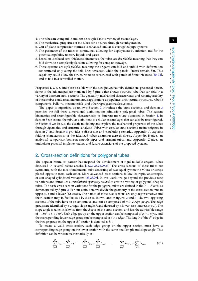
axes; that is θB = 180◦ − θA, and the edge lengths are aU1 = aL1 = bU1 = bL1. This tube can befully flattened in the X − Y plane and can also be folded into a flat state in the Y − Z plane.However, as will be shown in Section 4, this most fundamental tube case is not reconfigurable.To create a reconfigurable tube, the cross-section must have at least three edge groups (m> 2)each with a unique slope angle θ. Although the slope angles can be arbitrary, in our work wedefine reconfigurable cross-sections with one edge group where θ= 90◦. When this cross-sectionis projected in the X − Y plane per Section 3(a), the θ= 90◦ edge group will be completely flat.As defined, the tube is at a fully extended state (100% extension), because from this state the flatedge group can only fold down. When folding, the θ= 90◦ edges serve as programmable bitsor switches to reconfigure the tube cross-section (see Section 4). A m> 2 cross-section that has noedge group with θ= 90◦, is not fully extended when initially defined, and the edges with θ closestto 90◦ serve as the switches.
Figure 4. (a) An admissible cross-section with the shape of a dog, created with six different edge groups. The upper section has
22 edges, while the lower section has 29. (b) Dog tube fully extended, and folded to 95% and 10% extension.
3. Three dimensional profile definitionsIn this section, we discuss the complete three dimensional definition of the tubes when apreviously defined Y − Z cross-section is used as a basis. The cross-section is projected inX − Y − Z space, to create a closed continuous tube. The tube definitions assume that the origamisheets have an infinitesimally small or zero-thickness. In practice, there is a technique that allowsfor thickness to be incorporated into the design of rigid foldable tubes [31], however we do nottake these details into account. In Section 3(a) we discuss the basic projection geometries thatpreserve the rigid and flat foldability of the polygonal origami tubes. With these definitions thecapability to reconfigure the cross-section is preserved allowing for a programmable system. The projectiondiscussed in Section 3(b) violates flat foldability conditions, but maintains rigid foldability and theprogrammable characteristics. The projection presented in Section 3(c) is the most geometricallyunrestricted, but it restricts folding for non-square, non-symmetric tubes. The programmablecharacteristics of the tubes are discussed in Section 4, and the folding properties are summarizedin Appendix A.
6
rspa.ro yalsocietypublishing.orgP
rocR
Soc
A0000000
...............................................................
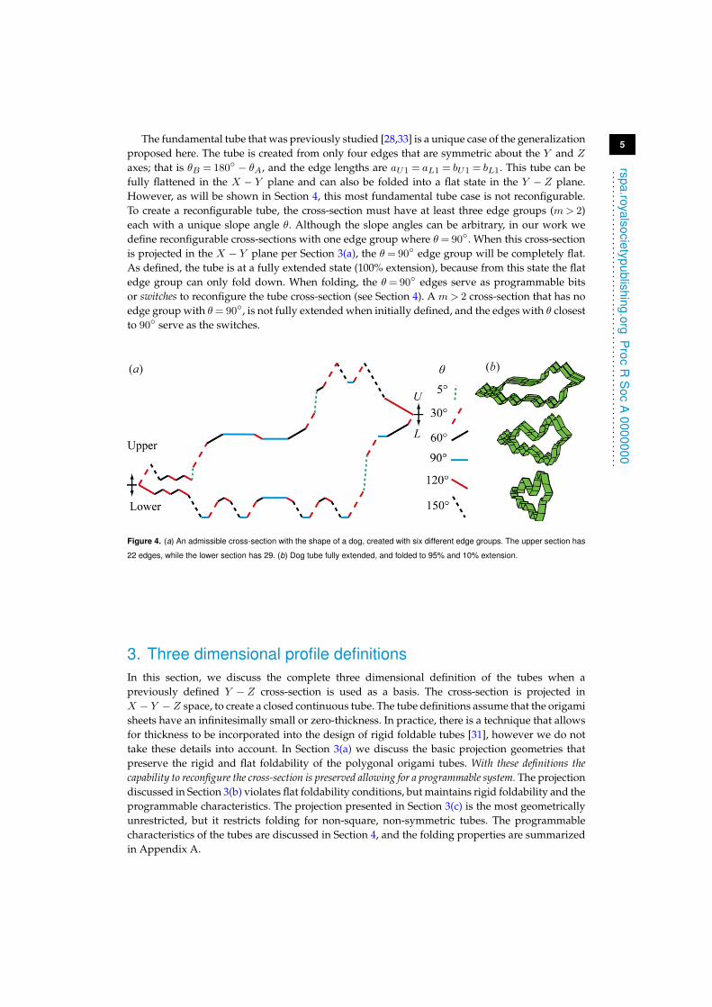
(a) Admissible projections for rigid and flat foldable polygonal origamitubes
The first geometric variation for the tubes is to project the the cross-section in the X − Y planewith a constant projection angle as shown in figure 5a-d. The projection is defined by an angleφ and length l. This projection creates a new cross-section that again lies only in the Y − Zplane and is parallel with the initial cross-section when looked at from above (X − Y plane). Thecorresponding edges of the two cross-sections are connected with thin origami sheets creating asystem of fold lines and panels. A different projection angle φ can be used to create a distinctlydifferent structure (figure 5b and c). The length of individual projected segments can also bevaried (figure 5d). When the base projection with no length variation is used, all panels areparallelograms and are the same for each cross-section edge. The left vertex angle (α) of eachpanel (internal angle of the parallelogram) can be calculated as αL = arccos(− sin(θ) ∗ cos(φ)).For other more complex projections discussed herein we leave the geometric derivations to thereader.
Figure 5. (a) Cross-section projection in the X-Y direction using a constant projection angle i.e. φ= φ1 = φ2 = φ3 = 60◦.
(b) Constant φ= 80◦ projection. (c) Constant φ= 40◦ projection. (d) Constant φ= 60◦ projection, with lengths of segment
i defined as: li = 0.4 + 0.2 ∗ i. (e) Projection with angle variation. Symmetry between the cross-section and projection vector
is preserved in the X-Y plane. (f ) A rigid foldable S-shaped tube constructed by following symmetry rules in (e). All tubes of this
figure use the cross-section in figure 2a.
The basic type of projection is further extended by allowing an angle shift to occur, where theprojection angles are not equal throughout (i.e. φ1 6= φ2 6= φ3...). Figure 5e shows the projectionwhere the angle is varied in the X − Y plane. Symmetry is enforced such that the adjacent vertexangles (α) about the cross-section are kept symmetric. This projection can be used to create anarbitrary geometry in the X − Y plane that is flat and rigid foldable.
7
rspa.royalsocietypublishing.orgP
rocR
Soc
A0000000
...............................................................
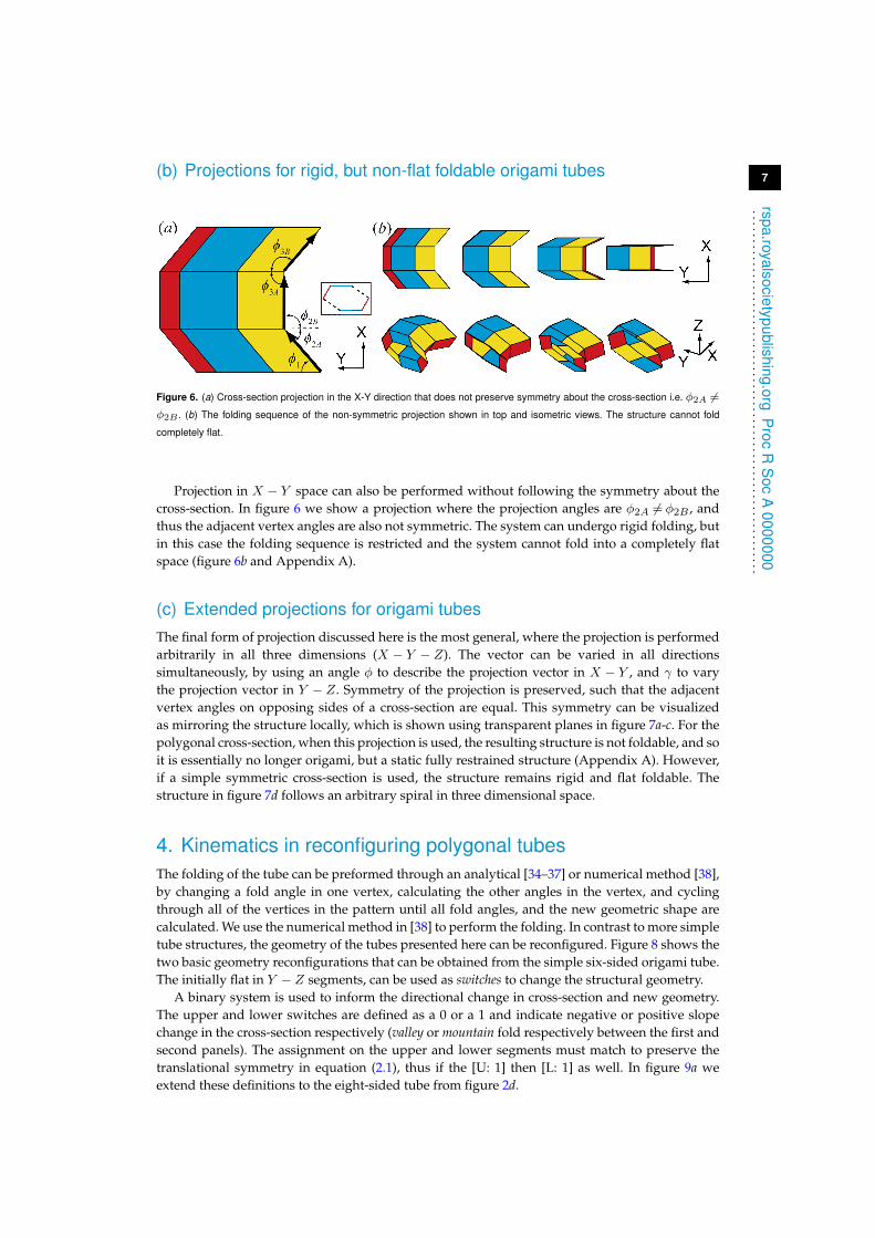
(b) Projections for rigid, but non-flat foldable origami tubes
Figure 6. (a) Cross-section projection in the X-Y direction that does not preserve symmetry about the cross-section i.e. φ2A 6=φ2B . (b) The folding sequence of the non-symmetric projection shown in top and isometric views. The structure cannot fold
completely flat.
Projection in X − Y space can also be performed without following the symmetry about thecross-section. In figure 6 we show a projection where the projection angles are φ2A 6= φ2B , andthus the adjacent vertex angles are also not symmetric. The system can undergo rigid folding, butin this case the folding sequence is restricted and the system cannot fold into a completely flatspace (figure 6b and Appendix A).
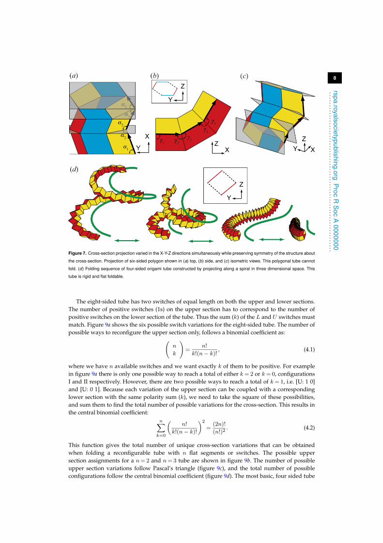
(c) Extended projections for origami tubesThe final form of projection discussed here is the most general, where the projection is performedarbitrarily in all three dimensions (X − Y − Z). The vector can be varied in all directionssimultaneously, by using an angle φ to describe the projection vector in X − Y , and γ to varythe projection vector in Y − Z. Symmetry of the projection is preserved, such that the adjacentvertex angles on opposing sides of a cross-section are equal. This symmetry can be visualizedas mirroring the structure locally, which is shown using transparent planes in figure 7a-c. For thepolygonal cross-section, when this projection is used, the resulting structure is not foldable, and soit is essentially no longer origami, but a static fully restrained structure (Appendix A). However,if a simple symmetric cross-section is used, the structure remains rigid and flat foldable. Thestructure in figure 7d follows an arbitrary spiral in three dimensional space.
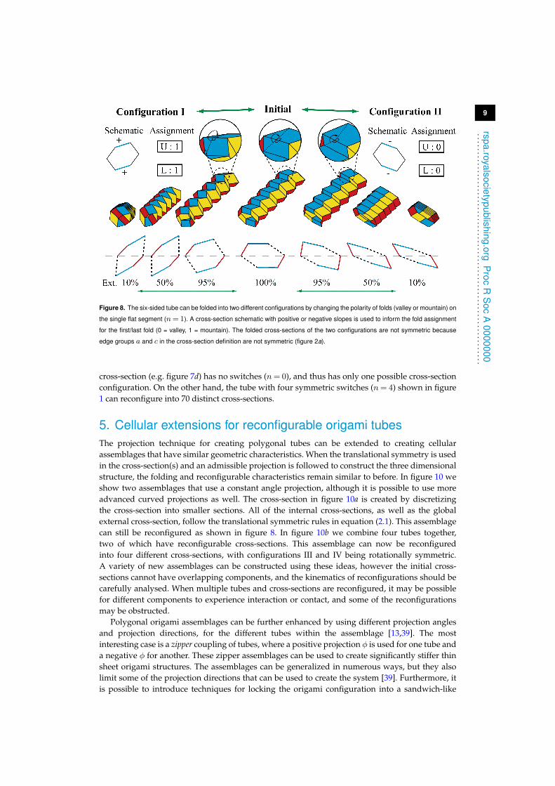
4. Kinematics in reconfiguring polygonal tubesThe folding of the tube can be preformed through an analytical [34–37] or numerical method [38],by changing a fold angle in one vertex, calculating the other angles in the vertex, and cyclingthrough all of the vertices in the pattern until all fold angles, and the new geometric shape arecalculated. We use the numerical method in [38] to perform the folding. In contrast to more simpletube structures, the geometry of the tubes presented here can be reconfigured. Figure 8 shows thetwo basic geometry reconfigurations that can be obtained from the simple six-sided origami tube.The initially flat in Y − Z segments, can be used as switches to change the structural geometry.
A binary system is used to inform the directional change in cross-section and new geometry.The upper and lower switches are defined as a 0 or a 1 and indicate negative or positive slopechange in the cross-section respectively (valley or mountain fold respectively between the first andsecond panels). The assignment on the upper and lower segments must match to preserve thetranslational symmetry in equation (2.1), thus if the [U: 1] then [L: 1] as well. In figure 9a weextend these definitions to the eight-sided tube from figure 2d.
8
rspa.ro yalsocietypublishing.orgP
rocR
Soc
A0000000
...............................................................
Figure 7. Cross-section projection varied in the X-Y-Z directions simultaneously while preserving symmetry of the structure about
the cross-section. Projection of six-sided polygon shown in (a) top, (b) side, and (c) isometric views. This polygonal tube cannot
fold. (d) Folding sequence of four-sided origami tube constructed by projecting along a spiral in three dimensional space. This
tube is rigid and flat foldable.
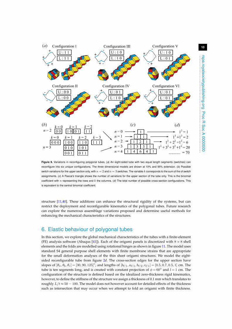
The eight-sided tube has two switches of equal length on both the upper and lower sections.The number of positive switches (1s) on the upper section has to correspond to the number ofpositive switches on the lower section of the tube. Thus the sum (k) of the L and U switches mustmatch. Figure 9a shows the six possible switch variations for the eight-sided tube. The number ofpossible ways to reconfigure the upper section only, follows a binomial coefficient as:(
n
k
)=
n!
k!(n− k)! , (4.1)
where we have n available switches and we want exactly k of them to be positive. For examplein figure 9a there is only one possible way to reach a total of either k= 2 or k= 0, configurationsI and II respectively. However, there are two possible ways to reach a total of k= 1, i.e. [U: 1 0]and [U: 0 1]. Because each variation of the upper section can be coupled with a correspondinglower section with the same polarity sum (k), we need to take the square of these possibilities,and sum them to find the total number of possible variations for the cross-section. This results inthe central binomial coefficient:
n∑k=0
(n!
k!(n− k)!
)2
=(2n)!
(n!)2. (4.2)
This function gives the total number of unique cross-section variations that can be obtainedwhen folding a reconfigurable tube with n flat segments or switches. The possible uppersection assignments for a n= 2 and n= 3 tube are shown in figure 9b. The number of possibleupper section variations follow Pascal’s triangle (figure 9c), and the total number of possibleconfigurations follow the central binomial coefficient (figure 9d). The most basic, four sided tube
9
rspa.ro yalsocietypublishing.orgP
rocR
Soc
A0000000
...............................................................
Figure 8. The six-sided tube can be folded into two different configurations by changing the polarity of folds (valley or mountain) on
the single flat segment (n= 1). A cross-section schematic with positive or negative slopes is used to inform the fold assignment
for the first/last fold (0 = valley, 1 = mountain). The folded cross-sections of the two configurations are not symmetric because
edge groups a and c in the cross-section definition are not symmetric (figure 2a).
cross-section (e.g. figure 7d) has no switches (n= 0), and thus has only one possible cross-sectionconfiguration. On the other hand, the tube with four symmetric switches (n= 4) shown in figure1 can reconfigure into 70 distinct cross-sections.
5. Cellular extensions for reconfigurable origami tubesThe projection technique for creating polygonal tubes can be extended to creating cellularassemblages that have similar geometric characteristics. When the translational symmetry is usedin the cross-section(s) and an admissible projection is followed to construct the three dimensionalstructure, the folding and reconfigurable characteristics remain similar to before. In figure 10 weshow two assemblages that use a constant angle projection, although it is possible to use moreadvanced curved projections as well. The cross-section in figure 10a is created by discretizingthe cross-section into smaller sections. All of the internal cross-sections, as well as the globalexternal cross-section, follow the translational symmetric rules in equation (2.1). This assemblagecan still be reconfigured as shown in figure 8. In figure 10b we combine four tubes together,two of which have reconfigurable cross-sections. This assemblage can now be reconfiguredinto four different cross-sections, with configurations III and IV being rotationally symmetric.A variety of new assemblages can be constructed using these ideas, however the initial cross-sections cannot have overlapping components, and the kinematics of reconfigurations should becarefully analysed. When multiple tubes and cross-sections are reconfigured, it may be possiblefor different components to experience interaction or contact, and some of the reconfigurationsmay be obstructed.
Polygonal origami assemblages can be further enhanced by using different projection anglesand projection directions, for the different tubes within the assemblage [13,39]. The mostinteresting case is a zipper coupling of tubes, where a positive projection φ is used for one tube anda negative φ for another. These zipper assemblages can be used to create significantly stiffer thinsheet origami structures. The assemblages can be generalized in numerous ways, but they alsolimit some of the projection directions that can be used to create the system [39]. Furthermore, itis possible to introduce techniques for locking the origami configuration into a sandwich-like
10
rspa.ro yalsocietypublishing.orgP
rocR
Soc
A0000000
...............................................................
Figure 9. Variations in reconfiguring polygonal tubes. (a) An eight-sided tube with two equal length segments (switches) can
reconfigure into six unique configurations. The three dimensional models are shown at 10% and 95% extension. (b) Possible
switch variations for the upper section only, withn= 2 andn= 3 switches. The variable k corresponds to the sum of the of switch
assignments. (c) A Pascal’s triangle shows the number of variations for the upper section of the tube only. This is the binomial
coefficient with n representing the rows and k the columns. (d) The total number of possible cross-section configurations. This
is equivalent to the central binomial coefficient.
structure [11,40]. These additions can enhance the structural rigidity of the systems, but canrestrict the deployment and reconfigurable kinematics of the polygonal tubes. Future researchcan explore the numerous assemblage variations proposed and determine useful methods forenhancing the mechanical characteristics of the structures.
6. Elastic behaviour of polygonal tubesIn this section, we explore the global mechanical characteristics of the tubes with a finite-element(FE) analysis software (Abaqus [41]). Each of the origami panels is discretized with 8× 8 shellelements and the folds are modelled using rotational hinges as shown in figure 11. The model usesstandard S4 general purpose shell elements with finite membrane strains that are appropriatefor the small deformation analyses of the thin sheet origami structures. We model the eight-sided reconfigurable tube from figure 2d. The cross-section edges for the upper section haveslopes of [θa, θb, θc] = [30, 90, 125]◦, and lengths of [bU1, aU1, bU2, cU1] = [0.5, 0.7, 0.5, 1] cm. Thetube is ten segments long, and is created with constant projection of φ= 60◦ and l= 1 cm. Theconfiguration of the structure is defined based on the idealized zero-thickness rigid kinematics,however, to define the stiffness of the structure we assign a thickness of 0.1 mm which translates toroughly L/t≈ 50− 100. The model does not however account for detailed effects of the thicknesssuch as intersection that may occur when we attempt to fold an origami with finite thickness.
11
rspa.royalsocietypublishing.orgP
rocR
Soc
A0000000
...............................................................
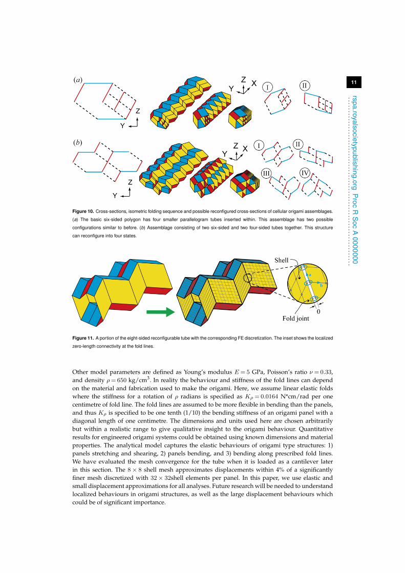
Figure 10. Cross-sections, isometric folding sequence and possible reconfigured cross-sections of cellular origami assemblages.
(a) The basic six-sided polygon has four smaller parallelogram tubes inserted within. This assemblage has two possible
configurations similar to before. (b) Assemblage consisting of two six-sided and two four-sided tubes together. This structure
can reconfigure into four states.
Figure 11. A portion of the eight-sided reconfigurable tube with the corresponding FE discretization. The inset shows the localized
zero-length connectivity at the fold lines.
Other model parameters are defined as Young’s modulus E = 5 GPa, Poisson’s ratio ν = 0.33,and density ρ= 650 kg/cm3. In reality the behaviour and stiffness of the fold lines can dependon the material and fabrication used to make the origami. Here, we assume linear elastic foldswhere the stiffness for a rotation of ρ radians is specified as Kρ = 0.0164 N*cm/rad per onecentimetre of fold line. The fold lines are assumed to be more flexible in bending than the panels,and thus Kρ is specified to be one tenth (1/10) the bending stiffness of an origami panel with adiagonal length of one centimetre. The dimensions and units used here are chosen arbitrarilybut within a realistic range to give qualitative insight to the origami behaviour. Quantitativeresults for engineered origami systems could be obtained using known dimensions and materialproperties. The analytical model captures the elastic behaviours of origami type structures: 1)panels stretching and shearing, 2) panels bending, and 3) bending along prescribed fold lines.We have evaluated the mesh convergence for the tube when it is loaded as a cantilever laterin this section. The 8× 8 shell mesh approximates displacements within 4% of a significantlyfiner mesh discretized with 32× 32shell elements per panel. In this paper, we use elastic andsmall displacement approximations for all analyses. Future research will be needed to understandlocalized behaviours in origami structures, as well as the large displacement behaviours whichcould be of significant importance.
12
rspa.royalsocietypublishing.orgP
rocR
Soc
A0000000
...............................................................
We use an eigenvalue analysis to explore the global mechanical properties of the reconfigurableorigami tube. These analyses can be used to determine how flexible or stiff the structure wouldbe for bending, twisting or other deformations. We obtain the eigenvalues λi and correspondingeigen-modes vi of the structure using a linear dynamics system of equations Kvi = λiMvi where(K) is the stiffness matrix and (M) is the mass matrix of the structure. The eigenvalues are arrangedin an incremental order (i) and represent the excitation frequencies that would deform thestructure into the corresponding eigen-mode. The eigenvalues are also proportional to the totalenergy of each eigen-mode (elastic strain energy and kinetic energy), meaning that eigen-modeswith higher eigenvalues require more energy to achieve the given deformation. The structure isanalysed with no boundary conditions, thus the first six eigenvalues are zero, with eigen-modesrepresenting rigid body motion of the structure in three-dimensional space (three displacementand three rotational modes). We start considering the seventh and subsequent eigen-modes of thestructure.
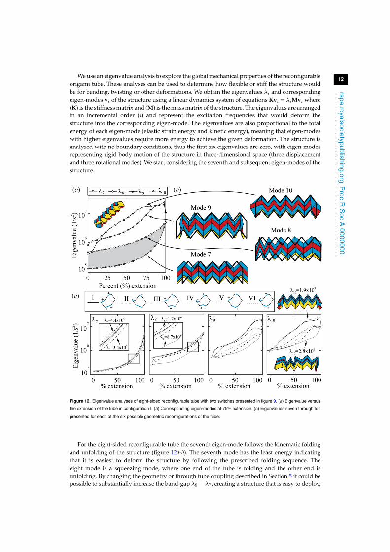
Figure 12. Eigenvalue analyses of eight-sided reconfigurable tube with two switches presented in figure 9. (a) Eigenvalue versus
the extension of the tube in configuration I. (b) Corresponding eigen-modes at 75% extension. (c) Eigenvalues seven through ten
presented for each of the six possible geometric reconfigurations of the tube.
For the eight-sided reconfigurable tube the seventh eigen-mode follows the kinematic foldingand unfolding of the structure (figure 12a-b). The seventh mode has the least energy indicatingthat it is easiest to deform the structure by following the prescribed folding sequence. Theeight mode is a squeezing mode, where one end of the tube is folding and the other end isunfolding. By changing the geometry or through tube coupling described in Section 5 it could bepossible to substantially increase the band-gap λ8 − λ7, creating a structure that is easy to deploy,
13
rspa.ro yalsocietypublishing.orgP
rocR
Soc
A0000000
...............................................................
but is substantially stiffer for other deformations. The ninth mode of the structure is anothermanifestation of squeezing with the centre unfolding and the ends folding . The tenth mode is alocalized mode, where the panels at the end of the tube fold. The ninth and tenth eigenvalues aresubstantially higher, meaning the structure is stiffer for these and other types of deformations.
Because the geometry of the system changes, the magnitudes of the eigenvalues also changewith respect to the extension of the system. Extension here is defined as a percentage of the fullyextended length. When the structure is at 0% extension it is completely folded down, while ata 100% extension the switches flatten and the system can be reconfigured. The eigenvalues forrigid folding and squeezing remain essentially the same regardless of the folded configuration,although there are some small differences in magnitude. However, the ninth and tenth modeare greatly affected by the different folding configurations (figure 12c). This is because the cross-sectional geometry has a higher influence in determining the more complex localized and globalbending modes.
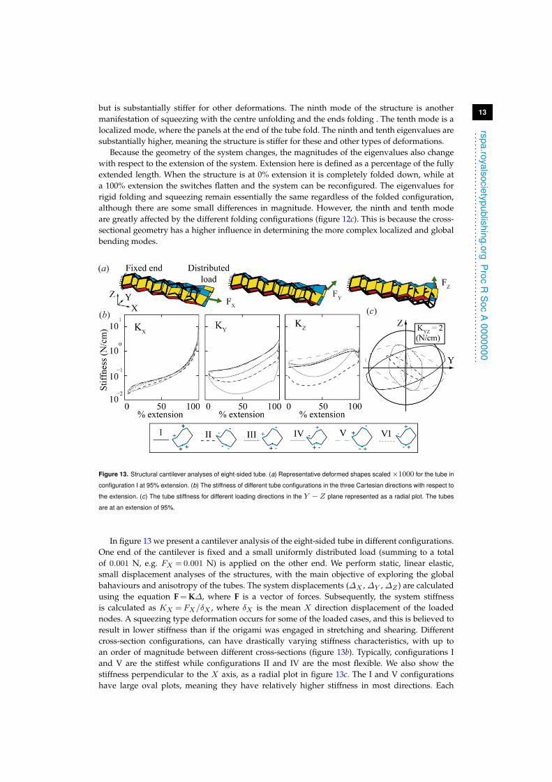
Figure 13. Structural cantilever analyses of eight-sided tube. (a) Representative deformed shapes scaled×1000 for the tube in
configuration I at 95% extension. (b) The stiffness of different tube configurations in the three Cartesian directions with respect to
the extension. (c) The tube stiffness for different loading directions in the Y − Z plane represented as a radial plot. The tubes
are at an extension of 95%.
In figure 13 we present a cantilever analysis of the eight-sided tube in different configurations.One end of the cantilever is fixed and a small uniformly distributed load (summing to a totalof 0.001 N, e.g. FX = 0.001 N) is applied on the other end. We perform static, linear elastic,small displacement analyses of the structures, with the main objective of exploring the globalbahaviours and anisotropy of the tubes. The system displacements (∆X , ∆Y , ∆Z ) are calculatedusing the equation F = K∆, where F is a vector of forces. Subsequently, the system stiffnessis calculated as KX = FX/δX , where δX is the mean X direction displacement of the loadednodes. A squeezing type deformation occurs for some of the loaded cases, and this is believed toresult in lower stiffness than if the origami was engaged in stretching and shearing. Differentcross-section configurations, can have drastically varying stiffness characteristics, with up toan order of magnitude between different cross-sections (figure 13b). Typically, configurations Iand V are the stiffest while configurations II and IV are the most flexible. We also show thestiffness perpendicular to the X axis, as a radial plot in figure 13c. The I and V configurationshave large oval plots, meaning they have relatively higher stiffness in most directions. Each
14
rspa.royalsocietypublishing.orgP
rocR
Soc
A0000000
...............................................................
of the cross-sections also has a different direction (in Y − Z) where it has a lower or higherstiffness. This phenomena indicates that the reconfigurable tubes have a highly adjustableanisotropy when used as cantilevers. The behaviours observed in this section show that the cross-section geometry can have a significant influence on the mechanical properties of the system.Thus, the reconfigurable polygonal tubes can be used to create highly tunable and adaptivestructural systems. Detailed research is needed in this area to determine the influence of differentcross-section geometries, as well as the tunability achieved from each reconfiguration.
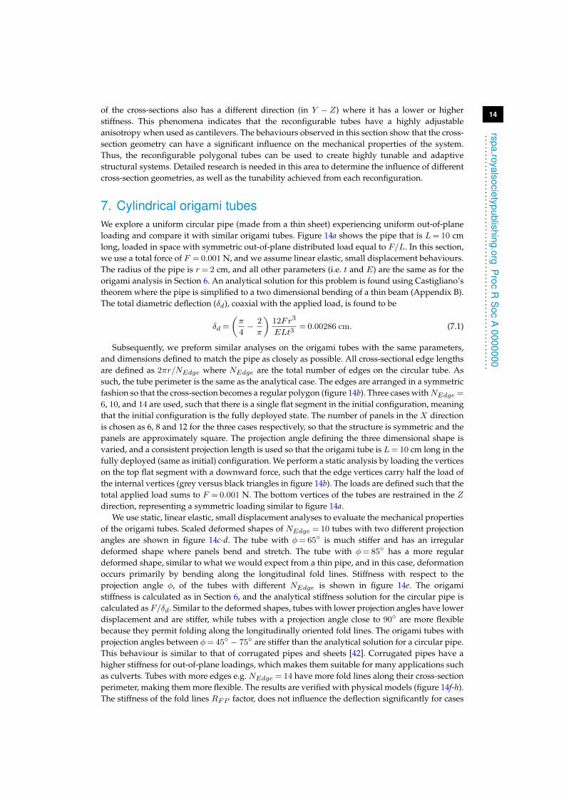
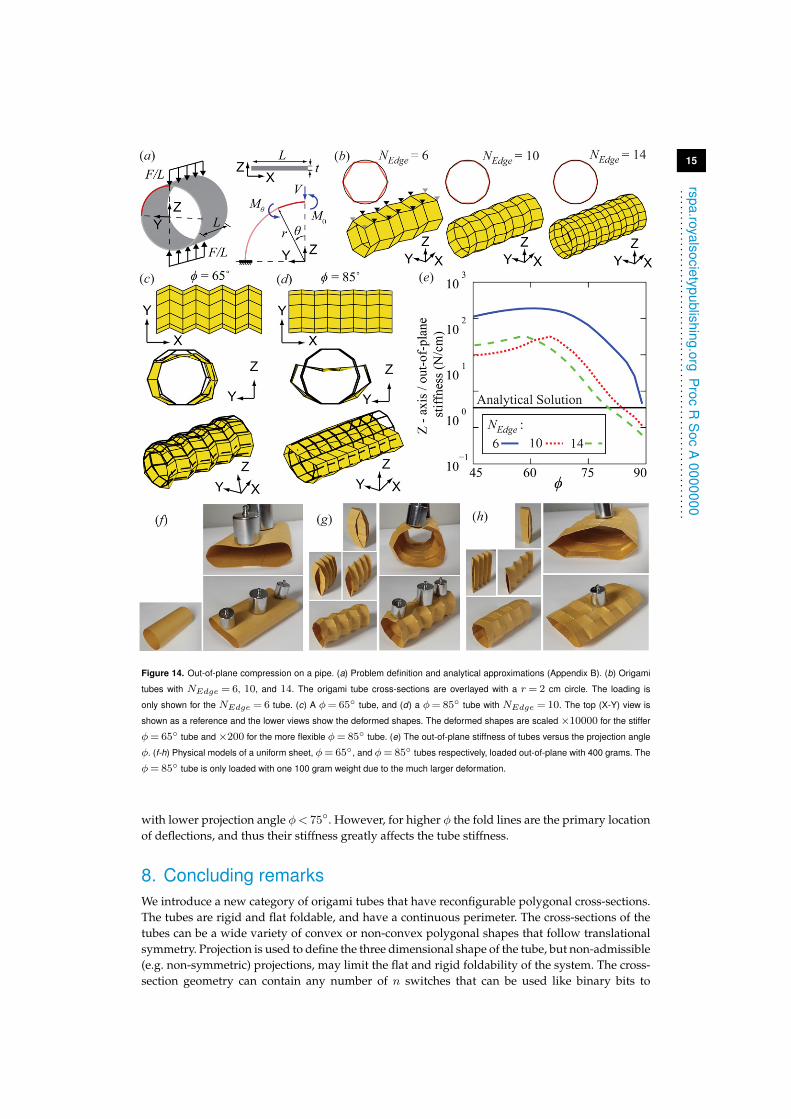
7. Cylindrical origami tubesWe explore a uniform circular pipe (made from a thin sheet) experiencing uniform out-of-planeloading and compare it with similar origami tubes. Figure 14a shows the pipe that is L= 10 cmlong, loaded in space with symmetric out-of-plane distributed load equal to F/L. In this section,we use a total force of F = 0.001 N, and we assume linear elastic, small displacement behaviours.The radius of the pipe is r= 2 cm, and all other parameters (i.e. t and E) are the same as for theorigami analysis in Section 6. An analytical solution for this problem is found using Castigliano’stheorem where the pipe is simplified to a two dimensional bending of a thin beam (Appendix B).The total diametric deflection (δd), coaxial with the applied load, is found to be
δd =
(π
4− 2
π
)12Fr3
ELt3= 0.00286 cm. (7.1)
Subsequently, we preform similar analyses on the origami tubes with the same parameters,and dimensions defined to match the pipe as closely as possible. All cross-sectional edge lengthsare defined as 2πr/NEdge where NEdge are the total number of edges on the circular tube. Assuch, the tube perimeter is the same as the analytical case. The edges are arranged in a symmetricfashion so that the cross-section becomes a regular polygon (figure 14b). Three cases withNEdge =6, 10, and 14 are used, such that there is a single flat segment in the initial configuration, meaningthat the initial configuration is the fully deployed state. The number of panels in the X directionis chosen as 6, 8 and 12 for the three cases respectively, so that the structure is symmetric and thepanels are approximately square. The projection angle defining the three dimensional shape isvaried, and a consistent projection length is used so that the origami tube is L= 10 cm long in thefully deployed (same as initial) configuration. We perform a static analysis by loading the verticeson the top flat segment with a downward force, such that the edge vertices carry half the load ofthe internal vertices (grey versus black triangles in figure 14b). The loads are defined such that thetotal applied load sums to F = 0.001 N. The bottom vertices of the tubes are restrained in the Zdirection, representing a symmetric loading similar to figure 14a.
We use static, linear elastic, small displacement analyses to evaluate the mechanical propertiesof the origami tubes. Scaled deformed shapes of NEdge = 10 tubes with two different projectionangles are shown in figure 14c-d. The tube with φ= 65◦ is much stiffer and has an irregulardeformed shape where panels bend and stretch. The tube with φ= 85◦ has a more regulardeformed shape, similar to what we would expect from a thin pipe, and in this case, deformationoccurs primarily by bending along the longitudinal fold lines. Stiffness with respect to theprojection angle φ, of the tubes with different NEdge is shown in figure 14e. The origamistiffness is calculated as in Section 6, and the analytical stiffness solution for the circular pipe iscalculated as F/δd. Similar to the deformed shapes, tubes with lower projection angles have lowerdisplacement and are stiffer, while tubes with a projection angle close to 90◦ are more flexiblebecause they permit folding along the longitudinally oriented fold lines. The origami tubes withprojection angles between φ= 45◦ − 75◦ are stiffer than the analytical solution for a circular pipe.This behaviour is similar to that of corrugated pipes and sheets [42]. Corrugated pipes have ahigher stiffness for out-of-plane loadings, which makes them suitable for many applications suchas culverts. Tubes with more edges e.g. NEdge = 14 have more fold lines along their cross-sectionperimeter, making them more flexible. The results are verified with physical models (figure 14f-h).The stiffness of the fold lines RFP factor, does not influence the deflection significantly for cases
15
rspa.ro yalsocietypublishing.orgP
rocR
Soc
A0000000
...............................................................
Figure 14. Out-of-plane compression on a pipe. (a) Problem definition and analytical approximations (Appendix B). (b) Origami
tubes with NEdge = 6, 10, and 14. The origami tube cross-sections are overlayed with a r= 2 cm circle. The loading is
only shown for the NEdge = 6 tube. (c) A φ= 65◦ tube, and (d) a φ= 85◦ tube with NEdge = 10. The top (X-Y) view is
shown as a reference and the lower views show the deformed shapes. The deformed shapes are scaled ×10000 for the stiffer
φ= 65◦ tube and×200 for the more flexible φ= 85◦ tube. (e) The out-of-plane stiffness of tubes versus the projection angle
φ. (f-h) Physical models of a uniform sheet, φ= 65◦, and φ= 85◦ tubes respectively, loaded out-of-plane with 400 grams. The
φ= 85◦ tube is only loaded with one 100 gram weight due to the much larger deformation.
with lower projection angle φ< 75◦. However, for higher φ the fold lines are the primary locationof deflections, and thus their stiffness greatly affects the tube stiffness.
8. Concluding remarksWe introduce a new category of origami tubes that have reconfigurable polygonal cross-sections.The tubes are rigid and flat foldable, and have a continuous perimeter. The cross-sections of thetubes can be a wide variety of convex or non-convex polygonal shapes that follow translationalsymmetry. Projection is used to define the three dimensional shape of the tube, but non-admissible(e.g. non-symmetric) projections, may limit the flat and rigid foldability of the system. The cross-section geometry can contain any number of n switches that can be used like binary bits to
16
rspa.ro yalsocietypublishing.orgP
rocR
Soc
A0000000
...............................................................
program the geometric reconfiguration of the cross-section. We show that the total number ofpossible cross-section variations for a tube follow the central binomial coefficient of n. A cellularcross-section or coupling of multiple tubes can be used to create a new variety of assemblagesthat enhance the functionality and reconfigurable properties of the tubes.
In addition to the geometric variations and reconfigurable kinematics, this paper also exploressome mechanical properties of the polygonal tubes. We show that the tubes have only oneflexible mode for kinematic deployment for which the stiffness is not significantly influenced byreconfiguring the cross-section. On the other hand, the cross-section configuration can influenceother deformation modes and the out-of-plane stiffness of the tubes. This property can be usedto make tunable structures that can change their mechanical properties. If the origami tubesare used as circular pipes, they can be designed to have a high out-of-plane stiffness similarto that of corrugated pipes. An appendix proposes future research directions on applications,fabrication, and non-linear deformations, all of which will enhance the practicality, functionalityand capability of the reconfigurable tubes. We envision that the physical attributes, versatility,and programmable characteristics of the polygonal origami tubes will enable solutions of varyingscale in science and engineering.
Data accessibility statement. The work does not have any experimental data.
Competing interests statement. We have no competing interests.
Authors’ contributions. ETF, GHP and TT designed the research, conceived the geometric designs andcomputational models, interpreted the results, and wrote the paper. All authors gave final approval forpublication.
Funding statement. This research was partially supported by the National Science Foundation (NSF) grantCMMI 1538830. The authors also acknowledge support from the NSF Graduate Research Fellowship; JapanSociety for the Promotion of Science Fellowship; Raymond Allen Jones Chair at the Georgia Institute ofTechnology; and Japan Science and Technology Agency Presto program.
Ethics statement. This work did not involve any human data.
Appendix A. Foldability of origami tubesIn this appendix we verify the developability, flat foldability and initial rigid foldability using theapproach introduced by Tachi [43]. We assume that the origami panels have an infinitesimallysmall or zero-thickness to satisfy the mathematical definitions. The origami tubes defined bySections 2 and 3 contain a total number of nvert internal vertices where four fold lines meet, anda number of npanel four-sided panels. The folding characteristics of the origami can be exploredby performing the following vector calculations for the vertices and panels:
cdev =
[2π −
4∑k=1
αk,i
]nvert×1
= 0, (8.1)
cflat =
[4∑k=1
(−1)kαk,i
]nvert×1
= 0, (8.2)
cplanar =[ρj]npanel×1
= 0, (8.3)
where αk,i represents the k-th vertex angle in the i-th vertex, and ρj represents the dihedral anglebetween the normals of two triangles that together create the j-th panel of the tube. When cdev = 0for all vertices, then the origami is developable, meaning it can be created from a single flat pieceof material. The origami tubes presented here have mostly non-developable vertices, and thusthey cannot be folded from a single flat piece of material. However, some of the vertices may bedevelopable and thus a portion of the tube may be constructed from an initially flat sheet (e.g.
17
rspa.royalsocietypublishing.orgP
rocR
Soc
A0000000
...............................................................
the single four-sided tube can be constructed from two flat sheets [28]). When cflat = 0, then allvertices of the origami are flat foldable meaning that, they can fold down to a flat 2 dimensionalstate. The definitions in Section 3(a) and 3(c) intentionally ensure symmetry when preforminga projection of the cross-section, thus they ensure that all vertices are flat foldable. However, inSection 3(b) where symmetry is not preserved, we loose the flat foldability (cflat 6= 0). Equation
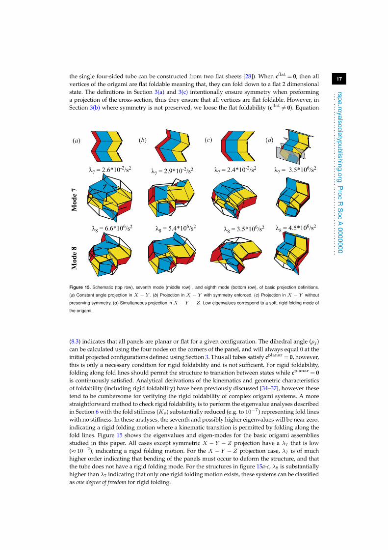
Figure 15. Schematic (top row), seventh mode (middle row) , and eighth mode (bottom row), of basic projection definitions.
(a) Constant angle projection in X − Y . (b) Projection in X − Y with symmetry enforced. (c) Projection in X − Y without
preserving symmetry. (d) Simultaneous projection in X − Y − Z. Low eigenvalues correspond to a soft, rigid folding mode of
the origami.
(8.3) indicates that all panels are planar or flat for a given configuration. The dihedral angle (ρj )can be calculated using the four nodes on the corners of the panel, and will always equal 0 at theinitial projected configurations defined using Section 3. Thus all tubes satisfy cplanar = 0, however,this is only a necessary condition for rigid foldability and is not sufficient. For rigid foldability,folding along fold lines should permit the structure to transition between states while cplanar = 0is continuously satisfied. Analytical derivations of the kinematics and geometric characteristicsof foldability (including rigid foldability) have been previously discussed [34–37], however thesetend to be cumbersome for verifying the rigid foldability of complex origami systems. A morestraightforward method to check rigid foldability, is to perform the eigenvalue analyses describedin Section 6 with the fold stiffness (Kρ) substantially reduced (e.g. to 10−7) representing fold lineswith no stiffness. In these analyses, the seventh and possibly higher eigenvalues will be near zero,indicating a rigid folding motion where a kinematic transition is permitted by folding along thefold lines. Figure 15 shows the eigenvalues and eigen-modes for the basic origami assembliesstudied in this paper. All cases except symmetric X − Y − Z projection have a λ7 that is low(≈ 10−2), indicating a rigid folding motion. For the X − Y − Z projection case, λ7 is of muchhigher order indicating that bending of the panels must occur to deform the structure, and thatthe tube does not have a rigid folding mode. For the structures in figure 15a-c, λ8 is substantiallyhigher than λ7 indicating that only one rigid folding motion exists, these systems can be classifiedas one degree of freedom for rigid folding.
18
rspa.ro yalsocietypublishing.orgP
rocR
Soc
A0000000
...............................................................
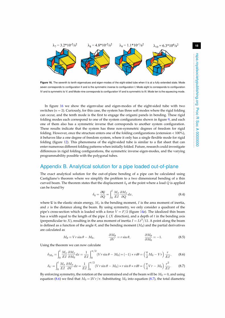
Figure 16. The seventh to tenth eigenvalues and eigen-modes of the eight-sided tube when it is at a fully extended state. Mode
seven corresponds to configuration II and is the symmetric inverse to configuration I; Mode eight is corresponds to configuration
IV and is symmetric to V; and Mode nine corresponds to configuration VI and is symmetric to III. Mode ten is the squeezing mode.
In figure 16 we show the eigenvalue and eigen-modes of the eight-sided tube with twoswitches (n= 2). Curiously, for this case, the system has three soft modes where the rigid foldingcan occur, and the tenth mode is the first to engage the origami panels in bending. These rigidfolding modes each correspond to one of the system configurations shown in figure 9, and eachone of them also has a symmetric inverse that corresponds to another system configuration.These results indicate that the system has three non-symmetric degrees of freedom for rigidfolding. However, once the structure enters one of the folding configurations (extension < 100%),it behaves like a one degree of freedom system, where it only has a single flexible mode for rigidfolding (figure 12). This phenomena of the eight-sided tube is similar to a flat sheet that canenter numerous different folding patterns when initially folded. Future, research could investigatedifferences in rigid folding configurations, the symmetric inverse eigen-modes, and the varyingprogrammability possible with the polygonal tubes.
Appendix B. Analytical solution for a pipe loaded out-of-planeThe exact analytical solution for the out-of-plane bending of a pipe can be calculated usingCastigliano’s theorem where we simplify the problem to a two dimensional bending of a thincurved beam. The theorem states that the displacement δq at the point where a load Q is appliedcan be found by
δq =∂U∂Q
=
∫ l0
Mx
EI
∂Mx
∂Qdx, (8.4)
where U is the elastic strain energy, Mx is the bending moment, I is the area moment of inertia,and x is the distance along the beam. By using symmetry, we only consider a quadrant of thepipe’s cross-section which is loaded with a force V = F/2 (figure 14a). The idealized thin beamhas a width equal to the length of the pipe L (X direction), and a depth of t in the bending axis(perpendicular to X), resulting in the area moment of inertia I =Lt3/12. A point along the beamis defined as a function of the angle θ, and the bending moment (Mθ) and the partial derivativesare calculated as
Mθ = V r sin θ −M0,∂Mθ
∂V= r sin θ,
∂Mθ
∂M0=−1. (8.5)
Using the theorem we can now calculate
δM0=
∫ l0
Mx
EI
∂Mx
∂M0dx=
1
EI
∫π/20
(V r sin θ −M0) ∗ (−1) ∗ rdθ=(π2M0 − V r
) r
EI, (8.6)
δV =
∫ l0
Mx
EI
∂Mx
∂Vdx=
1
EI
∫π/20
(V r sin θ −M0) ∗ r sin θ ∗ rdθ=(π4V r −M0
) r2
EI. (8.7)
By enforcing symmetry, the rotation at the unrestrained end of the beam will beM0 = 0, and usingequation (8.6) we find that M0 = 2V r/π. Substituting M0 into equation (8.7), the total diametric
19
rspa.ro yalsocietypublishing.orgP
rocR
Soc
A0000000
...............................................................
deflection coaxial with the applied load is found to be
2δV = 2
(π
4− 2
π
)V r3
EI=
(π
4− 2
π
)12Fr3
ELt3. (8.8)
If we wish to find the total diametric deflection perpendicular with the applied load, we can usea fictitious load H applied horizontally at the free end of the curved beam, and use the samemethodology to find
2δH = 2
(2
π− 1
2
)V r3
EI=
(2
π− 1
2
)12Fr3
ELt3. (8.9)
Appendix C. Practical considerations and future extensions forreconfigurable origami tubesIn this appendix we propose future research on the reconfigurable tubes to explore (a) practicalapplications, (b) considerations for physical fabrication, and (c) non-linear behaviours that canextended capabilities. This section is meant to inform and motivate future research, rather than toprovide a holistic discussion on the different topics.
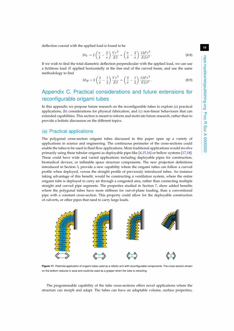
(a) Practical applicationsThe polygonal cross-section origami tubes discussed in this paper open up a variety ofapplications in science and engineering. The continuous perimeter of the cross-sections couldenable the tubes to be used in fluid flow applications. More traditional applications would involveprimarily using these tubular origami as deployable pipe-like [4,15,16] or bellow systems [17,18].These could have wide and varied applications including deployable pipes for construction,biomedical devices, or inflatable space structure components. The new projection definitionsintroduced in Section 3, provide a new capability where the origami tubes can follow a curvedprofile when deployed, versus the straight profile of previously introduced tubes. An instancetaking advantage of this benefit, would be constructing a ventilation system, where the entireorigami tube is deployed to carry air through a congested area, rather than connecting multiplestraight and curved pipe segments. The properties studied in Section 7, show added benefitswhere the polygonal tubes have more stiffness for out-of-plane loading, than a conventionalpipe with a constant cross-section. This property could allow for the deployable constructionof culverts, or other pipes that need to carry large loads.
Figure 17. Potential application of origami tubes used as a robotic arm with reconfigurable components. The cross-section shown
on the bottom reduces in area and could be used as a gripper when the tube is retracting.
The programmable capability of the tube cross-sections offers novel applications where thestructure can morph and adapt. The tubes can have an adaptable volume, surface properties,
20
rspa.ro yalsocietypublishing.orgP
rocR
Soc
A0000000
...............................................................
mechanical characteristics and more, simply through reconfiguring the polygonal cross-section.For example, components placed inside aircraft wing could be used to change the lift and dragproperties of the wing for different stages of flight [6]. The variable stiffness properties of theorigami tubes discussed in Section 6 could allow for new devices in aerospace, mechanical, andcivil engineering. Robotic components, such as the deployable and reconfigurable arm in figure17 could be designed to simultaneously fulfil multiple functions. A griper can be used with thereconfigurable cross-section, while the cellular divisions could add stiffness and carry electricalwiring, pneumatic tubes, or other utilities (e.g. similar to multi-functional dental tools). Althoughthese applications are still far from reality, they offer many potential advancements from currentday engineering approaches.
(b) Design and fabrication
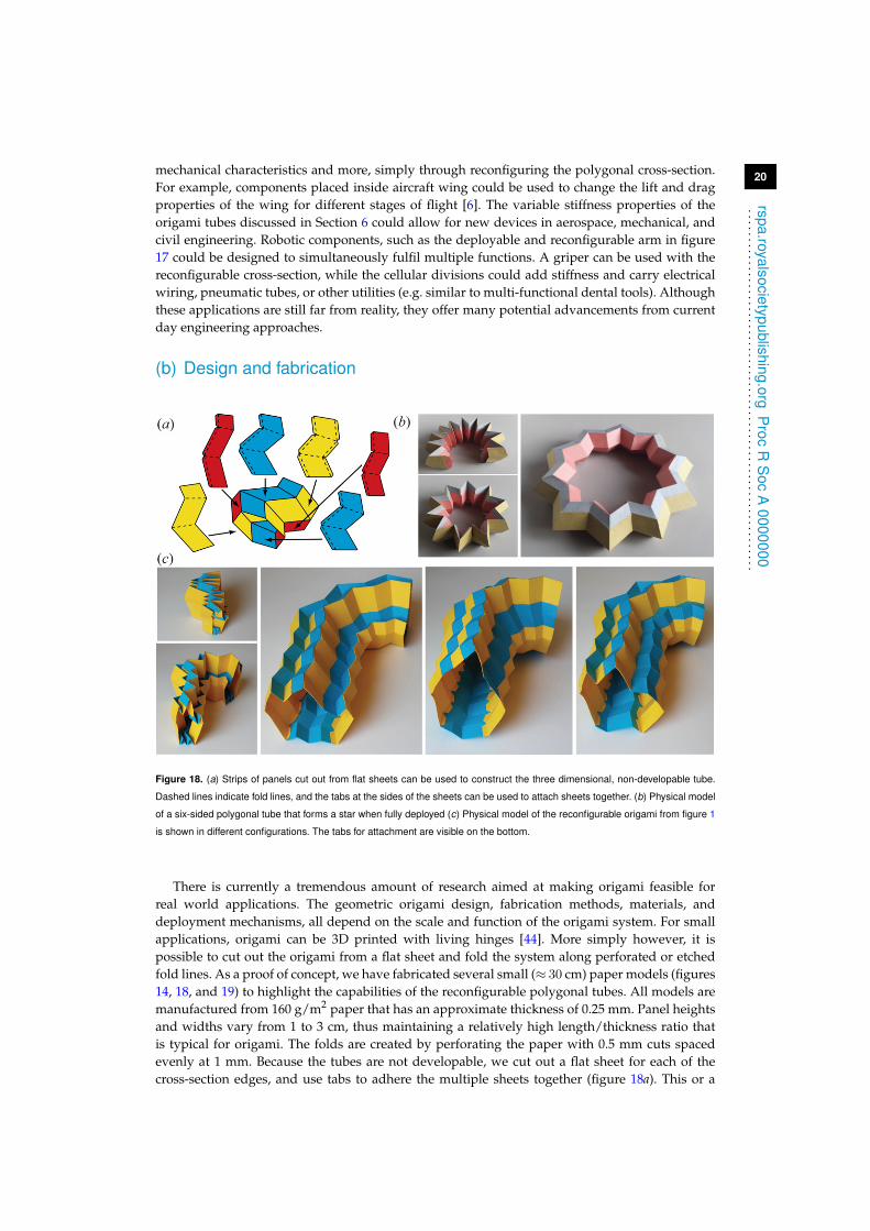
Figure 18. (a) Strips of panels cut out from flat sheets can be used to construct the three dimensional, non-developable tube.
Dashed lines indicate fold lines, and the tabs at the sides of the sheets can be used to attach sheets together. (b) Physical model
of a six-sided polygonal tube that forms a star when fully deployed (c) Physical model of the reconfigurable origami from figure 1
is shown in different configurations. The tabs for attachment are visible on the bottom.
There is currently a tremendous amount of research aimed at making origami feasible forreal world applications. The geometric origami design, fabrication methods, materials, anddeployment mechanisms, all depend on the scale and function of the origami system. For smallapplications, origami can be 3D printed with living hinges [44]. More simply however, it ispossible to cut out the origami from a flat sheet and fold the system along perforated or etchedfold lines. As a proof of concept, we have fabricated several small (≈ 30 cm) paper models (figures14, 18, and 19) to highlight the capabilities of the reconfigurable polygonal tubes. All models aremanufactured from 160 g/m2 paper that has an approximate thickness of 0.25 mm. Panel heightsand widths vary from 1 to 3 cm, thus maintaining a relatively high length/thickness ratio thatis typical for origami. The folds are created by perforating the paper with 0.5 mm cuts spacedevenly at 1 mm. Because the tubes are not developable, we cut out a flat sheet for each of thecross-section edges, and use tabs to adhere the multiple sheets together (figure 18a). This or a
21
rspa.royalsocietypublishing.orgP
rocR
Soc
A0000000
...............................................................
similar methodology would need to be used for manufacturing the polygonal origami out offlat sheets. When extending origami to the medium scales it is possible to use layered compositeswhere a flexible sheet that allows folding is sandwiched between more rigid panels [2,8,45]. Largeorigami structures could be constructed by using thickened panels interconnected by hingesrather than fold lines. For various applications in the real world the finite thickness of origamisheets begins to affect the system behaviour, and the idealized zero-thickness assumptions areno longer valid. Current research aims to account for thickness in kinematics and manufacturingin order to prevent self-intersection while minimizing the size of the stowed structure [30–32].To make the reconfigurable polygonal tubes reliable and cost effective for industrial applicationsmore innovation will still be needed. In particular, research should explore: materials and systemsto allow multiple folding/unfolding cycles; rapid fabrication methods; mechanisms to facilitatedeployment; and incorporating thickness into the tube design. The programmable switches of thepolygonal tubes may also require new methods for rapid or remote actuation and reconfiguration.
(c) Non-linear deformations and extensions
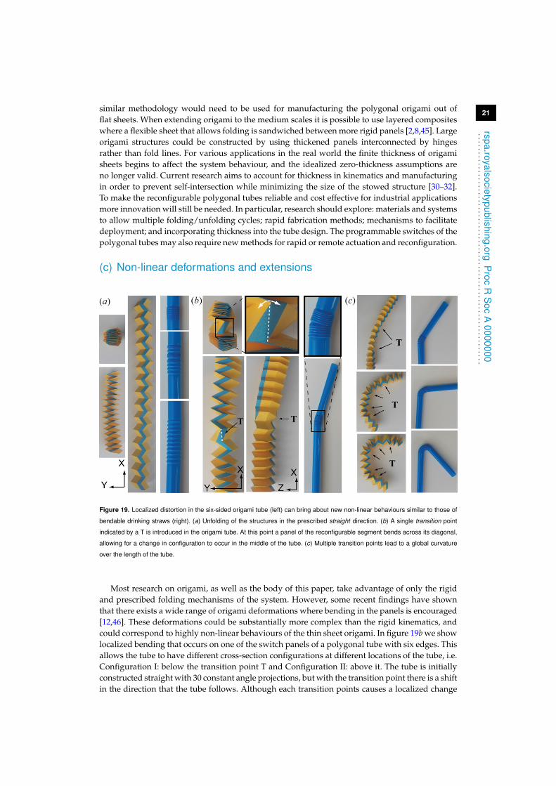
Figure 19. Localized distortion in the six-sided origami tube (left) can bring about new non-linear behaviours similar to those of
bendable drinking straws (right). (a) Unfolding of the structures in the prescribed straight direction. (b) A single transition point
indicated by a T is introduced in the origami tube. At this point a panel of the reconfigurable segment bends across its diagonal,
allowing for a change in configuration to occur in the middle of the tube. (c) Multiple transition points lead to a global curvature
over the length of the tube.
Most research on origami, as well as the body of this paper, take advantage of only the rigidand prescribed folding mechanisms of the system. However, some recent findings have shownthat there exists a wide range of origami deformations where bending in the panels is encouraged[12,46]. These deformations could be substantially more complex than the rigid kinematics, andcould correspond to highly non-linear behaviours of the thin sheet origami. In figure 19b we showlocalized bending that occurs on one of the switch panels of a polygonal tube with six edges. Thisallows the tube to have different cross-section configurations at different locations of the tube, i.e.Configuration I: below the transition point T and Configuration II: above it. The tube is initiallyconstructed straight with 30 constant angle projections, but with the transition point there is a shiftin the direction that the tube follows. Although each transition points causes a localized change
22
rspa.royalsocietypublishing.orgP
rocR
Soc
A0000000
...............................................................
in direction, as more transition points are included, the origami tube can go from a straight toa curved structure. This phenomena is similar to conventional bending drinking straws 19c. Thephysical models of the polygonal tubes also showed some bistable and multi-stable effects, similarto other origami structures [46–48]. Multi-stability with the reconfigurable tubes could providenew ideas and applications. More complex tube cross-sections where more switches could beaugmented, or longer tubes could lead to other interesting bending and non-linear effects.
References1. Randall CL, Gultepe E, Gracias DH. 2012 Self-folding devices and materials for biomedical
applications. Trends Biotechnology 30, 138-46.2. Ma KY, Felton SM, Wood RJ. 2012 Design, fabrication, and modelling of the split actuator
microrobotic bee. IEEE/RSJ Int. Conf. on Intelligent Robots and Systems (Vilamoura, Portugal)pp. 1133-1140.
3. Greenberg HC, Gong ML, Magleby SP, Howell LL. 2011 Identifying links between origami andcompliant mechanisms. Mech. Sci. 2, 217-225.
4. Martinez RV, Fish CR, Chen X, Whitesides GM. 2012 Elastomeric origami: Programmablepaper-elastomer composites as pneumatic actuators. Advanced Functional Mater. 22, 1376-1384.
5. Lang RJ. 2011 Origami Design Secrets, 2nd edn. CRC Press.6. Barbarino S, Bilgen O, Ajaj RM, Friswell MI, Inman DJ. 2011 A review of morphing aircraft. J.
Intelligent Mater. Systems and Struct. 22, 823-877.7. Del Grosso AE, Basso P. 2010 Adaptive building skin structures. Smart Mater. and Struct. 19,
124011.8. Hawkes E, An B, Benbernoub NM, Tanaka H, Kim S, Demaine ED, Rus D, Wood RJ. 2010
Programmable matter by folding. Proc. Natl. Acad. Sci. USA 107, 12441-12445.9. Marras AE, Zhou L, Su H-J, Castro CE. 2015 Programmable motion of DNA origami
mechanisms. Proc. Natl. Acad. Sci. USA 112, 713-718.10. Fuchi K, Diaz AR, Rothwell EJ, Ouedraogo RO, Tang J. An origami tunable metamaterial. J.
Appl. Phys. 111, 084905.11. Schenk M, Guest SD. 2013 Geometry of Miura-folded metamaterials. Proc. Natl. Acad. Sci. USA
110, 3276-3281.12. Silverberg JL, Evans AA, McLeod L, Hayward RC, Hull T, Santangelo CD, Cohen I. 2014
Using origami design principles to fold reprogrammable mechanical metamaterials. Science345, 647-650.
13. Filipov ET, Tachi T, Paulino GH. 2015 Origami tubes assembled into stiff, yet reconfigurablestructures and metamaterials. Proc. Natl. Acad. Sci. USA 112, 12321-12326.
14. Kuribayashi K, Tsuchiya K, You Z, Tomus D, Umemoto M, Ito T, Sasaki M. 2006 Self-deployable origami stent grafts as a biomedical application of Ni-rich TiNi shape memory alloyfoil. Mater. Sci. and Eng. A 419, 131-137.
15. Schenk M, Kerr SG, Smyth AM, Guest SD. 2013 Inflatable cylinders for deployable spacestructures. Proc. the First Conference Transformables 2013 in the Honor of Emilio Perez Piñero Seville,Spain.
16. Schenk M, Viquerat AD, Seffen KA, Guest SD. 2014 Review of inflatable booms for deployablespace structures: Packing and rigidization. J. of Spacecraft and Rockets 51, 762-778.
17. Yasuda H, Yein T, Tachi T, Miura K, Taya M. 2013 Folding behaviour of Tachi-Miurapolyhedron bellows. Proc. R. Soc. A 469, 20130351.
18. Francis KC, Rupert LT, Lang RJ, Morgan DC, Magleby SP, Howell LL. 2014 From crease patternto product: considerations to engineering origami-adapted designs. Proc. ASME 2014 IEDTC &CIEC (Buffalo, NY) pp. V05BT08A030.
19. Song J, Chen Y, Lu G. 2012 Axial crushing of thin-walled structures with origami patterns.Thin-Walled Struct. 54, 65-71.
20. Ma J, You Z. 2013 Energy absorption of thin-walled square tubes with a prefolded origamipattern-Part I: Geometry and numerical simulation. J. Appl. Mech. 81, 011003.
23
rspa.ro yalsocietypublishing.orgP
rocR
Soc
A0000000
...............................................................
21. Ma J, You Z. 2013 Energy absorption of thin-walled beams with a pre-folded origami pattern.Thin-Walled Struct. 73, 198-206.
22. Gattas JM, You Z. 2015 The behaviour of curved-crease foldcores under low-velocity impactloads. Int. J. Solids. Struct. 53, 80-91.
23. Cheung KC, Tachi T, Calisch S, Miura K. 2014 Origami interleaved tube cellular materials.Smart Mater. and Struct. 23, 094012.
24. Li S, Wang KW. 2015 Fluidic origami with embedded pressure dependent multi-stability: aplant inspired innovation. J. R. Soc. Interface 12: 20150639.
25. Miura K, Tachi T. 2010 Synthesis of rigid-foldable cylindrical polyhedra. J. the Int. Soc. for theInterdisciplinary Study of Symmetry (Gmuend, Austria) pp. 204-313.
26. Yasuda H, Yang J. 2015 Reentrant origami-based metamaterials with negative poisson’s ratioand bistability. Phys. Rev. Lett. 114, 185502.
27. Tsunoda H, Senbokuya Y, and Watanabe M. 2005 Deployment characteristics evaluation ofinflatable tubes with polygon folding under airplane microgravity environment. Space Tech. 25,127-137.
28. Tachi T. 2009 One-Dof cylindrical deployable structures with rigid quadrilateral panels. Proc.Int. Assoc. Shell and Spatial Struct. (Valencia, Spain) pp. 2295-2305.
29. Tachi T, Miura K. 2012 Rigid-foldable cylinders and cells. J. Int. Assoc. Shell and Spatial Struct.53, 217-226.
30. Hoberman C. 2010 Folding structures made of thick hinged sheets - US Patent #7,794,019B2,14.
31. Tachi T. 2011 Rigid-foldable thick origami. Origami 5, eds Wang-Iverson P, Lang RJ, Yim M(CRC) pp. 253-263.
32. Chen Y, Peng R, You Z. 2015 Origami of thick panels. Science 349, 396-400.33. Filipov ET, Tachi T, Paulino GH. 2015 Toward optimization of stiffness and flexibility of rigid,
flat-foldable origami structures. Origami 6 (In press).34. Huffman DA. 1976 Curvature and creases: A primer on paper. IEEE Trans. Comput. C-25, 1010-
1019.35. Hull TC. 2012 Project origami: activities for exploring mathematics, 2nd edn. CRC Press.36. belcastro sm, Hull TC. 2002 Modelling the folding of paper into three dimensions using affine
transformations. Linear Algebra and its Applications 348, 273-282.37. belcastro sm, Hull TC. 2002 A mathematical model for non-flat origami. Origami 3 pp. 39-51.38. Tachi T. 2009 Simulation of rigid origami. Origami 4 pp. 175-187.39. Tachi T, Filipov ET, Paulino GH 2015 Deployable folded-core sandwich panels guided
by a generating surface. Proc. Int. Assoc. Shell and Spatial Struct. Amsterdam, Netherlands(Accepted).
40. Gattas JM, You Z. 2015 Geometric assembly of rigid-foldable morphing sandwich structures.Engineering Structures 94:149-159.
41. Abaqus FEA 2010 Version 6.10 Documentation, Dassault Systemes Simulia Corp. Providence,RI, USA.
42. Briassoulis D 1986 Equivalent orthotropic properties of corrugated sheets. Comput. Struct. 23,129-138.
43. Tachi T. 2009 Generalization of rigid foldable quadrilateral mesh origami. Proc. Int. Assoc. Shelland Spatial Struct. (Valencia, Spain) pp. 2287-2294.
44. Deng D, Chen Y. 2013 An origami inspired additive manufacturing process for building thin-shell structures. ASME 2013 IMECE Volume 2A: Advanced Manufacturing (San Diego, CA) pp.V02AT02A016.
45. Peraza-Hernandez EA, Hartl DJ, Malak Jr RJ, Lagoudas DC. 2014 Origami-inspired activestructures: a synthesis and review. Smart Mater. and Struct. 23, 094001.
46. Silverberg JL, Na J-H, Evans AA, Liu B, Hull TC, Santangelo CD, Lang RJ, Hayward RC,Cohen I. 2015 Origami structures with a critical transition to bistability arising from hiddendegrees of freedom. Nature Mater. 14, 389-393.
47. Hanna BH, Lund JM, Lang RJ, Magleby SP, Howell LL. 2014 Waterbomb base: a symmetricsingle-vertex bistable origami mechanism. Smart Mater. and Struct. 23, 094009.
24
rspa.royalsocietypublishing.orgP
rocR
Soc
A0000000
...............................................................
48. Waitukaitis S, Menaut R, Chen BG-g, van Hecke M. 2015 Origami Multistabilty: From SingleVertices to Metasheets. Phys. Rev. Lett. 114, 055503.
Related Documents