TMVW Orbital Motors Technical Information

Welcome message from author
This document is posted to help you gain knowledge. Please leave a comment to let me know what you think about it! Share it to your friends and learn new things together.
Transcript

TMVW Orbital Motors
Technical Information

2 520L0728 • Rev BC • Nov 2012
TMVW Technical Information
F300030 Tif
Sauer-Danfoss is a world leader within production of low speed orbital motors with high torque. We can offer more than 1600 different orbital motors, categorised in types, variants and sizes (incl. different shaft versions).
The motors vary in size (rated displacement) from 8 cm3 [0.50 in3] to 800 cm3 [48.9 in3] per revolution.
Speeds range up to approx. 2500 min-1 (rpm) for the smallest type and up to approx. 600 min-1 (rpm) for the largest type.
Maximum operating torques vary from 13 N•m [115 lbf•in] to 2700 N•m [24.000 lbf•in] (peak) and maximum outputs are from 2,0 kW [2,7 hp] to 70 kW [95 hp].
Characteristic features:
• Smooth running over the entire speed range• Constant operating torque over a wide speed range• High starting torque• High return pressure without the use of drain line (High pressure shaft seal)• High efficiency• Long life under extreme operating conditions• Robust and compact design• High radial and axial bearing capacity• For applications in both open and closed loop hydraulic systems• Suitable for a wide variety of hydraulics fluidsThe programme is characterised by technical features appealing to a large number
A Wide Range of Orbital Motors
A Wide Range of Orbital Motors
© 2010 Sauer-Danfoss. All rights reserved.
Sauer-Danfoss accepts no responsibility for possible errors in catalogs, brochures and other printed material. Sauer -Danfoss reserves the right to alter its products without prior notice. This also applies to products already ordered provided that such alterations can be made without affecting agreed specifications. All trademarks in this material are properties of their respective owners. Sauer-Danfoss, the Sauer-Danfoss logotype, the Sauer-Danfoss S-icon, PLUS+1™, What really matters is inside® and Know-How in Motion™ are trademarks of the Sauer-Danfoss Group. Front page: F300 927, F300 928, F300 930, F300 932, F300 030, drawing:151Z21
3520L0728 • Rev BC • Nov 2012
TMVW Technical InformationA Wide Range of Orbital Motors
of applications and a part of the programme is characterised by motors that can be adapted to a given application. Adaptions comprise the following variants among others:
• Motors with corrosion resistant parts• Wheel motors with recessed mounting flange • OMP, OMR- motors with needle bearing• OMR motor in low leakage version• OMR motors in a super low leakage version• Short motors without bearings• Ultra short motors• Motors with integrated positive holding brake• Motors with integrated negative holding brake• Motors with integrated flushing valve• Motors with speed sensor• Motors with tacho connection• All motors are available with black finish paint
The Sauer-Danfoss orbital motors are used in the following application areas:
• Construction equipment• Agricultural equipment• Material handling & Lifting equipment• Forestry equipment• Lawn and turf equipment• Special purpose• Machine tools and stationary equipment• Marine equipment
Detailed data on all Sauer-Danfoss motors can be found in our motor catalogue, which is divided into 6 individual subcatalogues:• General information on Sauer-Danfoss orbital motors: function, use, selection of hydraulic motor, hydraulic systems, etc.• Technical data on small motors: OML and OMM• Technical data on medium sized motors: OMP, OMR, OMH and OMEW• Technical data on medium sized motors: DH and DS• Technical data on large motors: OMS, OMT and OMV• Technical data on large motors: TMVW• Technical data on large motors: TMT
A general survey brochure on Sauer-Danfoss orbital motors gives a quick motor reference based on power, torque, speed and capabilities.
Survey of Literature with Technical Data on Sauer-Danfoss Orbital Motors
A Wide Range of Orbital Motors(continued)
4 520L0728 • Rev BC • Nov 2012
TMVW Technical InformationContents
Contents
Versions
Code Numbers
Technical Data
Dimensions
Weight
Speed and torque ......................................................................................................................................... 5
Versions .............................................................................................................................................................. 6
Code Numbers ................................................................................................................................................ 7
Technical Data ................................................................................................................................................. 8Max. Permissible shaft seal pressure, pressure drop in motor ....................................................... 9Oil flow in drain line, direction of shaft rotation ...............................................................................10Permissible shaft load ................................................................................................................................11Port thread versions ....................................................................................................................................12
Dimensions .....................................................................................................................................................13
Weight of Motors ..........................................................................................................................................15
Table of RevisionsDate Page Changed RevOct 2004 All Major update BMar 2010 16 Japan location BBSep 2010 16 New back cover BCNov 2012 3 Planetary gears deleted BD
Revision History

5520L0728 • Rev BC • Nov 2012
TMVW Technical InformationData Survey
Speed and Torque
Peak values Intermittend values Continuous values
The bar diagrams above are useful for a quick selection of relevant motor size for the application.
6 520L0728 • Rev BC • Nov 2012
TMVW Technical Information
Mou
ntin
g fla
nge
Spig
ot d
iam
eter
Bolt
cir
cle
diam
eter
(BC)
Shaf
t
Port
siz
e
Euro
pean
ver
sion
US
vers
ion
Side
por
t ver
sion
End
port
ver
sion
Stan
dard
sha
ft s
eal
Dra
in c
onne
ctio
n
Chec
k va
lve
Mai
n ty
pe d
esig
nati
on
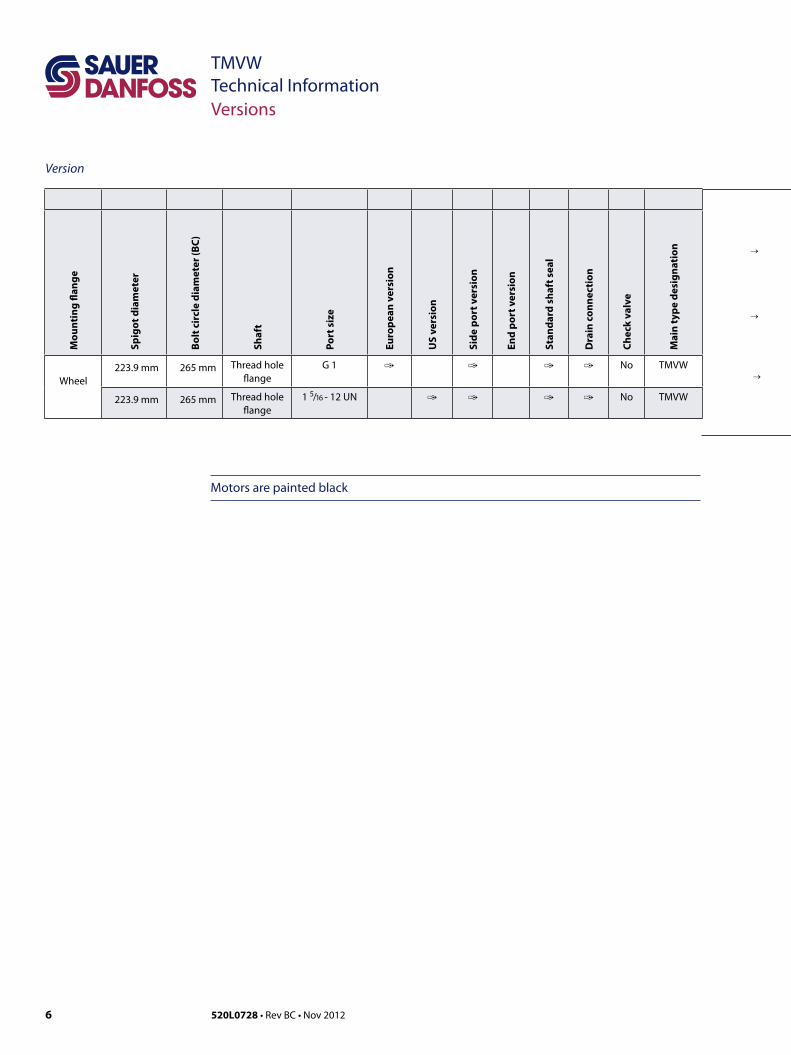
Wheel223.9 mm 265 mm Thread hole
flangeG 1 � � � � No TMVW
223.9 mm 265 mm Thread hole flange
1 5/16 - 12 UN � � � � No TMVW
→
→
→
Version
Motors are painted black
Versions

7520L0728 • Rev BC • Nov 2012
TMVW Technical Information
→ →→ →
Code Numbers
OrderingAdd the four digit prefix “151Z” to the four digit numbers from the chart for complete code number.
Example: 151Z8207 for an TMVW 630 with mounting flange ∅ 223.9 mm, port size G 1 and side port version.
Orders will not be accepted without the four digit prefix.
Code Numbers
Code
num
bers
Displacement (cm3)
Tech
nica
l dat
a - p
age
Dim
ensi
ons
- pag
e
400 500 630 800
151Z 8205 8206 8207 8208 8 13
151Z 8210 8211 8212 8213 8 14
→
→
→
8 520L0728 • Rev BC • Nov 2012
TMVW Technical InformationTechnical Data
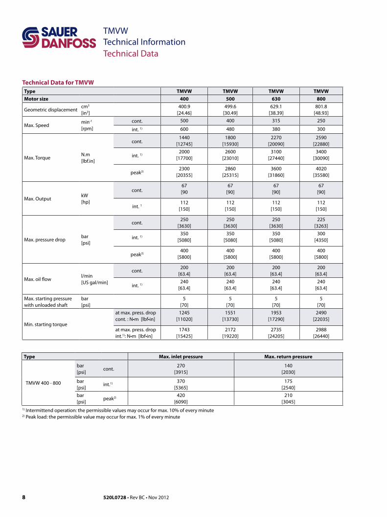
Technical Data for TMVWType TMVW TMVW TMVW TMVWMotor size 400 500 630 800
Geometric displacement cm3
[in3]400.9
[24.46]499.6
[30.49]629.1
[38.39]801.8
[48.93]
Max. Speedmin-1
[rpm]cont. 500 400 315 250
int. 1) 600 480 380 300
Max. Torque N.m[lbf.in]
cont.1440
[12745]1800
[15930]2270
[20090]2590
[22880]
int. 1)2000
[17700]2600
[23010]3100
[27440]3400
[30090]
peak2)2300
[20355]2860
[25315]3600
[31860]4020
[35580]
Max. OutputkW[hp]
cont.67[90
67[90]
67[90]
67[90]
int. 1112
[150]112
[150]112
[150]112
[150]
Max. pressure drop bar[psi]
cont.250
[3630]250
[3630]250
[3630]225
[3263]
int. 1)350
[5080]350
[5080]350
[5080]300
[4350]
peak2)400
[5800]400
[5800]400
[5800]400
[5800]
Max. oil flow l/min [US gal/min]
cont.200
[63.4]200
[63.4]200
[63.4]200
[63.4]
int. 1)240
[63.4]240
[63.4]240
[63.4]240
[63.4]
Max. starting pressure with unloaded shaft
bar[psi]
5[70]
5[70]
5[70]
5[70]
Min. starting torque
at max. press. drop cont. : N•m [lbf•in]
1245[11020]
1551[13730]
1953[17290]
2490[22035]
at max. press. drop int.1): N•m [lbf•in]
1743[15425]
2172[19220]
2735[24205]
2988[26440]
Type Max. inlet pressure Max. return pressure
TMVW 400 - 800
bar[psi]
cont.270
[3915]140
[2030]
bar[psi]
int.1) 370 [5365]
175 [2540]
bar[psi]
peak2) 420 [6090]
210[3045]
1) Intermittend operation: the permissible values may occur for max. 10% of every minute2) Peak load: the permissible value may occur for max. 1% of every minute
9520L0728 • Rev BC • Nov 2012
TMVW Technical InformationTechnical Data
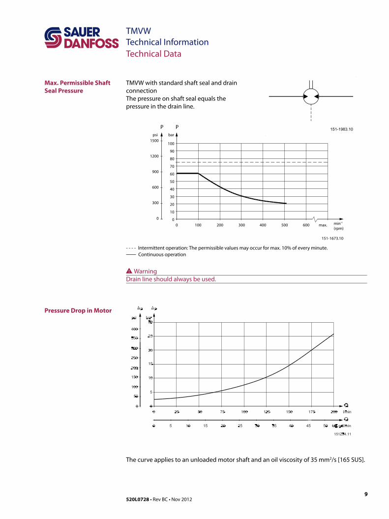
Max. Permissible Shaft Seal Pressure
Pressure Drop in Motor
TMVW with standard shaft seal and drain connectionThe pressure on shaft seal equals the pressure in the drain line.
WWarningDrain line should always be used.
151-1673.10
0 100 200 300 400 500 600 max.
1500
1200
900
600
300
0
100
90
80
70
60
50
40
30
20
10
0
psi bar
P P
min-1
(rpm)
- - - - Intermittent operation: The permissible values may occur for max. 10% of every minute. Continuous operation
The curve applies to an unloaded motor shaft and an oil viscosity of 35 mm2/s [165 SUS].

10 520L0728 • Rev BC • Nov 2012
TMVW Technical InformationTechnical Data
Oil Flow in Drain Line
Direction of Shaft Rotation
The table below shows the max. oil flow in the drain line at a return pressure less than 5-10 bar [75-150 psi].
Pressuredropbar
[psi]
Viscosity
mm2/s [SUS]
Oil flow in drain line
l/min [US gal/min]
200[2900]
20[100]
2.5[0.66]
35[165]
1.5[0.4]
275[3990]
20[100]
4.0[1.1]
35[165]
2.5[0.66]

11520L0728 • Rev BC • Nov 2012
TMVW Technical InformationTechnical Data
Permissible Shaft Load for TMVW
Permissible radial shaft loadThe output shaft runs in tapered roller bearings that permit high axial and radial forces.
The permissible radial load on the shaft is shown for an axial load of 0 N as a function of the distance from the mounting flange to the point of load application.
The curve is based on B10 Bearing life (2000 hours or 12 000 000 shaft revolutions at 100 min-1) at rated output torque, when mineral-based hydraulic oil with a sufficient content of anti-wear additives, is used.

12 520L0728 • Rev BC • Nov 2012
TMVW Technical InformationTechnical Data
Port Thread Versions
A: G Main portE : ISO 228/1 – G 1
C: G Drain portG: ISO 228/1 – G 1/4
B: UNF Main portF: 1 5/16 – 12 UN O-ring boss port
D: UNF Drain portH: 9/16 – 18 UNF O-ring boss port
A B
C D
G H
E F
151-1978.10
min
. 13
[0.5
1]
min
. 12
[0.4
7]
Ø22.5 [0.886]Ø22.0 [0.866]
min
. 18
[0.7
1]
min
. 19
[0.7
5]
Ø45.5 [1.791]Ø45.0 [1.772]

13520L0728 • Rev BC • Nov 2012
TMVW Technical Information
Dimensions
Dimensions, European Version
Wheel flange-spigot diameter ∅ 223.9 mm - BC ∅ 265 mm
C: G 1 ; 18 mm [0.67 in] deepD: Drain connection G 1/4 ; 12 mm [0.47 in] deepE: ∅ 17.6F: 6 • M16 • 1.5
TypeL1
mm [in]L2
mm [in]
TMVW 400293.4 [11.6]
116.5[4.6]
TMVW 500301.4[11.9]
124.5[4.9]
TMVW 630311.9[12.3]
135[5.3]
TMVW 800325.9[12.8]
149[5.9]

14 520L0728 • Rev BC • Nov 2012
TMVW Technical Information
Dimensions Wheel flange-spigot diameter ∅ 223.9 mm - BC ∅ 265 mm
US-Version
C: 1 5/16 - 12 UN; 19 mm [0.75 in] deepD: Drain connection 9/16 - 18 UNF; 13 mm [0.51 in] deepE: ∅ 17.6F: 6 • M16 • 1.5
TypeL1
mm [in]L2
mm [in]
TMVW 400293.4 [11.6]
116.5[4.6]
TMVW 500301.4[11.9]
124.5[4.9]
TMVW 630311.9[12.3]
135[5.3]
TMVW 800325.9[12.8]
149[5.9]
15520L0728 • Rev BC • Nov 2012
TMVW Technical InformationWeight of Motors
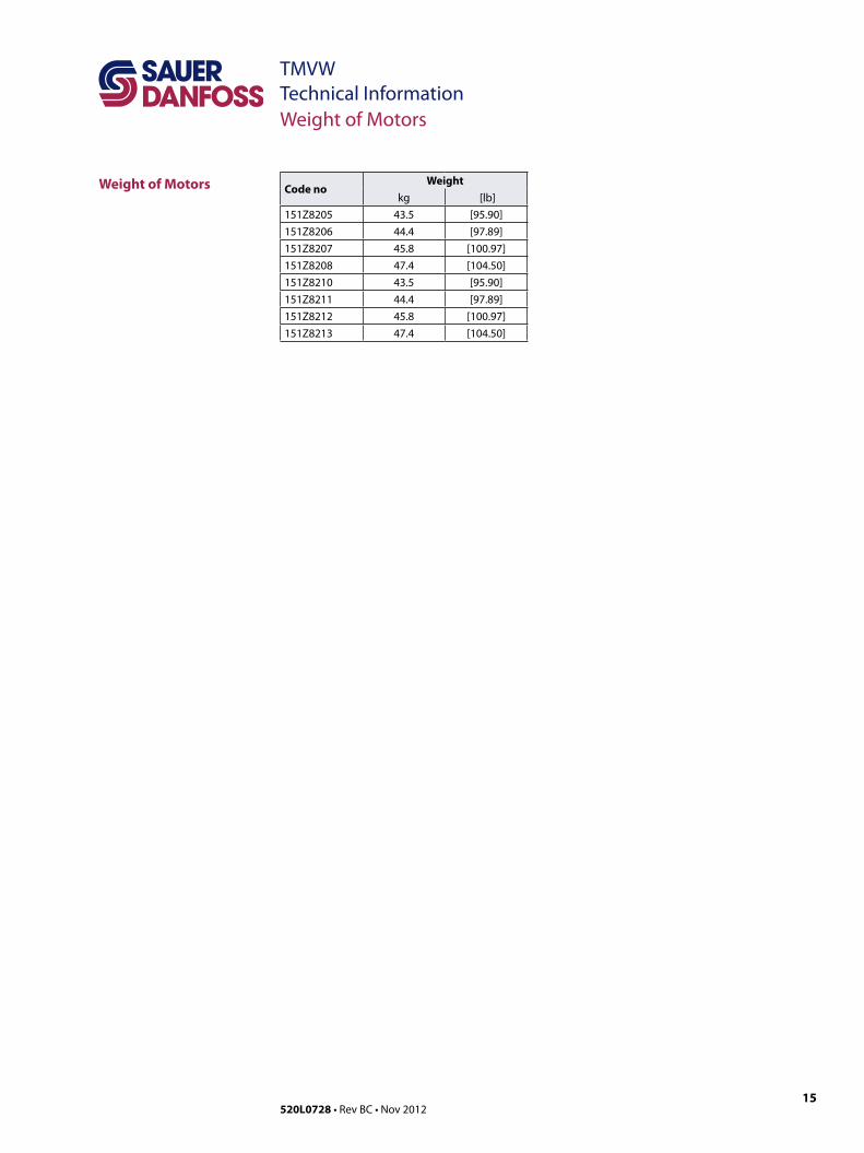
Weight of Motors Code noWeight
kg [lb]151Z8205 43.5 [95.90]151Z8206 44.4 [97.89]151Z8207 45.8 [100.97]151Z8208 47.4 [104.50]151Z8210 43.5 [95.90]151Z8211 44.4 [97.89]151Z8212 45.8 [100.97]151Z8213 47.4 [104.50]

Local address:
Sauer-Danfoss GmbH & Co. OHGPostfach 2460, D-24531 NeumünsterKrokamp 35, D-24539 Neumünster, GermanyPhone: +49 4321 871 0Fax: +49 4321 871 122
Sauer-Danfoss ApSDK-6430 Nordborg, DenmarkPhone: +45 7488 4444Fax: +45 7488 4400
Sauer-Danfoss is a global manufacturer and supplier of high-quality hydraulic and electronic components. We specialize in providing state-of-the-art technology and solutions that excel in the harsh operating conditions of the mobile o� -highway market. Building on our extensive applications expertise, we work closely with our customers to ensure exceptional performance for a broad range of o� -highway vehicles.
We help OEMs around the world speed up system development, reduce costs and bring vehicles to market faster. Sauer-Danfoss – Your Strongest Partner in Mobile Hydraulics.
Go to www.sauer-danfoss.com for further product information.
Wherever o� -highway vehicles are at work, so is Sauer-Danfoss.
We o� er expert worldwide support for our customers, ensuring the best possible solutions for outstanding performance. And with an extensive network of Global Service Partners, we also provide comprehensive global service for all of our components.
Please contact the Sauer-Danfoss representative nearest you.
Products we o� er:
• Bent Axis Motors
• Closed Circuit Axial Piston Pumps and Motors
• Displays
• Electrohydraulic Power Steering
• Electrohydraulics
• Hydraulic Power Steering
• Integrated Systems
• Joysticks and Control Handles
• Microcontrollers and Software
• Open Circuit Axial Piston Pumps
• Orbital Motors
• PLUS+1™ GUIDE
• Proportional Valves
• Sensors
• Steering
• Transit Mixer Drives
Members of the Sauer-Danfoss Group:
Comatrolwww.comatrol.com
Schwarzmüller-Inverterwww.schwarzmueller-inverter.com
Turolla www.turollaocg.com
Valmovawww.valmova.com
Hydro-Gear www.hydro-gear.com
Sauer-Danfoss-Daikinwww.sauer-danfoss-daikin.com
Sauer-Danfoss (US) Company2800 East 13th StreetAmes, IA 50010, USAPhone: +1 515 239 6000Fax: +1 515 239 6618
Sauer-Danfoss-Daikin LTD.Shin-Osaka TERASAKI 3rd Bldg. 6F1-5-28 Nishimiyahara, Yodogawa-kuOsaka 532-0004, JapanPhone: +81 6 6395 6066Fax: +81 6 6395 8585
w w w . s a u e r - d a n f o s s . c o m520L0728 • Rev BC • Nov 2012
Related Documents