ORB Feature Extraction and Matching in Hardware Josh Weberruss * , Lindsay Kleeman, Tom Drummond Department of Electrical and Computer Systems Engineering Monash University, Australia {firstname.lastname}@monash.edu Abstract The ORB (Oriented FAST (Features from Ac- celerated Segment Test) and Rotated BRIEF (Binary Robust Independent Elementary Fea- tures)) feature extractor is the state of the art in wide baseline matching with sparse image features for robotic vision. All previous im- plementations have employed general-purpose computing hardware, such as CPUs and GPUs. This work seeks to investigate the applicabil- ity of special-purpose computing hardware, in the form of Field-Programmable Gate Arrays (FPGAs), to the acceleration of this problem. FPGAs offer lower power consumption and higher frame rates than general hardware. A working implementation on an Altera Cyclone II (a low-cost FPGA suitable for development work, and available with a camera and screen interface) is described. 1 Introduction A recurrent and crucial problem in robotics is the local- isation of a robotic vehicle in space. Accurate positional information is vital for ensuring a robot does not get lost, and for ensuring that it is able to perform its task. Visual odometry is a family of algorithms that are used to track the motion of a robotic vehicle in space, using only information from one or more cameras. These algo- rithms provide a piecewise path representing the move- ment of the robot and the environment around it, al- lowing for localisation of the vehicle. There are several different approaches to visual odometry, the most com- mon of which track sparse (point-based) features through multiple frames of video. Many implementations of visual odometry have al- ready been demonstrated over the preceding decades, * This work was supported by the Australian Research Council Centre of Excellence for Robotic Vision (project number CE140100016) but most previous efforts have focused on CPU imple- mentation. This paper examines the applicability of ded- icated hardware to the first part of the visual odometry problem, namely the identification of sparse feature cor- respondences between images, in the context of a Field- Programmable Gate Array (FPGA) processor. FPGAs are large-scale integrated circuits that are de- signed to be reprogrammed in the field by means of switching many tens of thousands of internal logic ele- ments. They are useful in the prototyping of application- specific integrated circuits (ASICs), because they do not require tooling up a semiconductor foundry for each mi- nor design revision, at the cost of maximum clock speed and some extra power usage. Our system has successfully performed feature detec- tion and brute-force matching at 19.2 MPix/s on de- velopment board hardware, the fastest rate the camera could feed pixels to the hardware. Due to the vertical blanking interval, in which time the camera sensor col- lects light from the image, the logic is sitting idle for ap- proximately 2/3 of the time, so at present, performance is entirely limited by the camera. 1.1 Problem Specification The problem is specified as follows. The hardware sys- tem receives at its input one pixel from an input im- age frame per clock cycle. The pixels are received in a row-major raster scan from the camera, with a verti- cal blanking interval between frames. Each new frame of video is marked (outside the scope of this paper) as being a keyframe or a regular frame. Keyframes are considered reference frames — all the features in such a frame are indexed and used as a comparison reference for following regular frames. The output of the system should be, for each regular frame, a list of point correspondences. Each correspondence is a pixel coordinate in the regular frame paired with a matching pixel coordinate in the reference frame. Thanks to algorithms of the RANSAC family, the out- put of the system is allowed to generate a small num- ber of false positive matches (outliers). Repeating pat-

Welcome message from author
This document is posted to help you gain knowledge. Please leave a comment to let me know what you think about it! Share it to your friends and learn new things together.
Transcript
ORB Feature Extraction and Matching in Hardware
Josh Weberruss∗, Lindsay Kleeman, Tom DrummondDepartment of Electrical and Computer Systems Engineering
Monash University, Australia{firstname.lastname}@monash.edu
Abstract
The ORB (Oriented FAST (Features from Ac-celerated Segment Test) and Rotated BRIEF(Binary Robust Independent Elementary Fea-tures)) feature extractor is the state of the artin wide baseline matching with sparse imagefeatures for robotic vision. All previous im-plementations have employed general-purposecomputing hardware, such as CPUs and GPUs.This work seeks to investigate the applicabil-ity of special-purpose computing hardware, inthe form of Field-Programmable Gate Arrays(FPGAs), to the acceleration of this problem.FPGAs offer lower power consumption andhigher frame rates than general hardware. Aworking implementation on an Altera CycloneII (a low-cost FPGA suitable for developmentwork, and available with a camera and screeninterface) is described.
1 IntroductionA recurrent and crucial problem in robotics is the local-isation of a robotic vehicle in space. Accurate positionalinformation is vital for ensuring a robot does not getlost, and for ensuring that it is able to perform its task.
Visual odometry is a family of algorithms that are usedto track the motion of a robotic vehicle in space, usingonly information from one or more cameras. These algo-rithms provide a piecewise path representing the move-ment of the robot and the environment around it, al-lowing for localisation of the vehicle. There are severaldifferent approaches to visual odometry, the most com-mon of which track sparse (point-based) features throughmultiple frames of video.
Many implementations of visual odometry have al-ready been demonstrated over the preceding decades,
∗This work was supported by the Australian ResearchCouncil Centre of Excellence for Robotic Vision (projectnumber CE140100016)
but most previous efforts have focused on CPU imple-mentation. This paper examines the applicability of ded-icated hardware to the first part of the visual odometryproblem, namely the identification of sparse feature cor-respondences between images, in the context of a Field-Programmable Gate Array (FPGA) processor.
FPGAs are large-scale integrated circuits that are de-signed to be reprogrammed in the field by means ofswitching many tens of thousands of internal logic ele-ments. They are useful in the prototyping of application-specific integrated circuits (ASICs), because they do notrequire tooling up a semiconductor foundry for each mi-nor design revision, at the cost of maximum clock speedand some extra power usage.
Our system has successfully performed feature detec-tion and brute-force matching at 19.2 MPix/s on de-velopment board hardware, the fastest rate the cameracould feed pixels to the hardware. Due to the verticalblanking interval, in which time the camera sensor col-lects light from the image, the logic is sitting idle for ap-proximately 2/3 of the time, so at present, performanceis entirely limited by the camera.
1.1 Problem SpecificationThe problem is specified as follows. The hardware sys-tem receives at its input one pixel from an input im-age frame per clock cycle. The pixels are received ina row-major raster scan from the camera, with a verti-cal blanking interval between frames. Each new frame ofvideo is marked (outside the scope of this paper) as beinga keyframe or a regular frame. Keyframes are consideredreference frames — all the features in such a frame areindexed and used as a comparison reference for followingregular frames. The output of the system should be, foreach regular frame, a list of point correspondences. Eachcorrespondence is a pixel coordinate in the regular framepaired with a matching pixel coordinate in the referenceframe.
Thanks to algorithms of the RANSAC family, the out-put of the system is allowed to generate a small num-ber of false positive matches (outliers). Repeating pat-
terns in the input images can cause such problems, wherematches can be ambiguous.
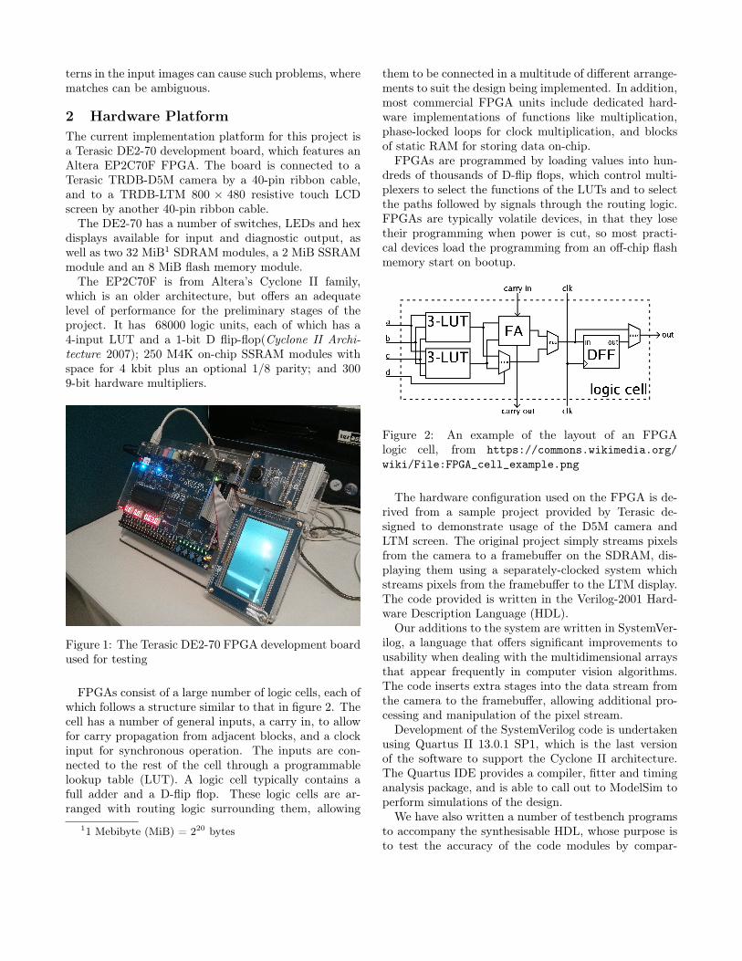
2 Hardware PlatformThe current implementation platform for this project isa Terasic DE2-70 development board, which features anAltera EP2C70F FPGA. The board is connected to aTerasic TRDB-D5M camera by a 40-pin ribbon cable,and to a TRDB-LTM 800 × 480 resistive touch LCDscreen by another 40-pin ribbon cable.
The DE2-70 has a number of switches, LEDs and hexdisplays available for input and diagnostic output, aswell as two 32 MiB1 SDRAM modules, a 2 MiB SSRAMmodule and an 8 MiB flash memory module.
The EP2C70F is from Altera’s Cyclone II family,which is an older architecture, but offers an adequatelevel of performance for the preliminary stages of theproject. It has 68000 logic units, each of which has a4-input LUT and a 1-bit D flip-flop(Cyclone II Archi-tecture 2007); 250 M4K on-chip SSRAM modules withspace for 4 kbit plus an optional 1/8 parity; and 3009-bit hardware multipliers.
Figure 1: The Terasic DE2-70 FPGA development boardused for testing
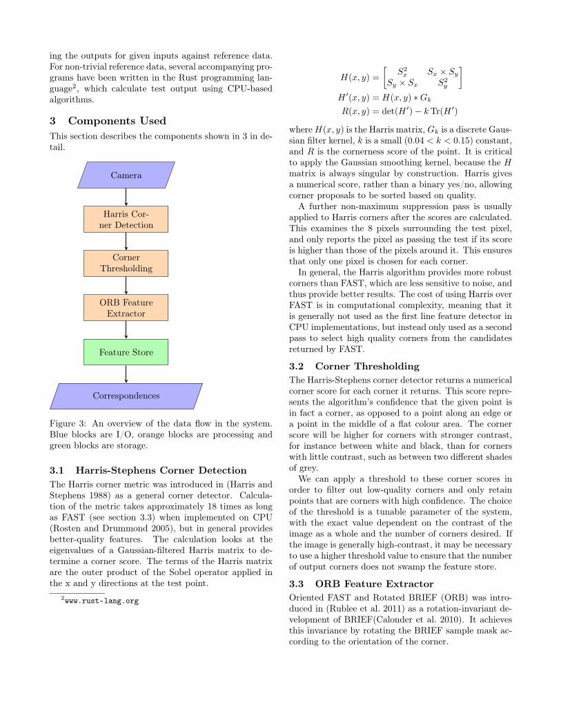
FPGAs consist of a large number of logic cells, each ofwhich follows a structure similar to that in figure 2. Thecell has a number of general inputs, a carry in, to allowfor carry propagation from adjacent blocks, and a clockinput for synchronous operation. The inputs are con-nected to the rest of the cell through a programmablelookup table (LUT). A logic cell typically contains afull adder and a D-flip flop. These logic cells are ar-ranged with routing logic surrounding them, allowing
11 Mebibyte (MiB) = 220 bytes
them to be connected in a multitude of different arrange-ments to suit the design being implemented. In addition,most commercial FPGA units include dedicated hard-ware implementations of functions like multiplication,phase-locked loops for clock multiplication, and blocksof static RAM for storing data on-chip.
FPGAs are programmed by loading values into hun-dreds of thousands of D-flip flops, which control multi-plexers to select the functions of the LUTs and to selectthe paths followed by signals through the routing logic.FPGAs are typically volatile devices, in that they losetheir programming when power is cut, so most practi-cal devices load the programming from an off-chip flashmemory start on bootup.
Figure 2: An example of the layout of an FPGAlogic cell, from https://commons.wikimedia.org/
wiki/File:FPGA_cell_example.png
The hardware configuration used on the FPGA is de-rived from a sample project provided by Terasic de-signed to demonstrate usage of the D5M camera andLTM screen. The original project simply streams pixelsfrom the camera to a framebuffer on the SDRAM, dis-playing them using a separately-clocked system whichstreams pixels from the framebuffer to the LTM display.The code provided is written in the Verilog-2001 Hard-ware Description Language (HDL).
Our additions to the system are written in SystemVer-ilog, a language that offers significant improvements tousability when dealing with the multidimensional arraysthat appear frequently in computer vision algorithms.The code inserts extra stages into the data stream fromthe camera to the framebuffer, allowing additional pro-cessing and manipulation of the pixel stream.
Development of the SystemVerilog code is undertakenusing Quartus II 13.0.1 SP1, which is the last versionof the software to support the Cyclone II architecture.The Quartus IDE provides a compiler, fitter and timinganalysis package, and is able to call out to ModelSim toperform simulations of the design.
We have also written a number of testbench programsto accompany the synthesisable HDL, whose purpose isto test the accuracy of the code modules by compar-
ing the outputs for given inputs against reference data.For non-trivial reference data, several accompanying pro-grams have been written in the Rust programming lan-guage2, which calculate test output using CPU-basedalgorithms.
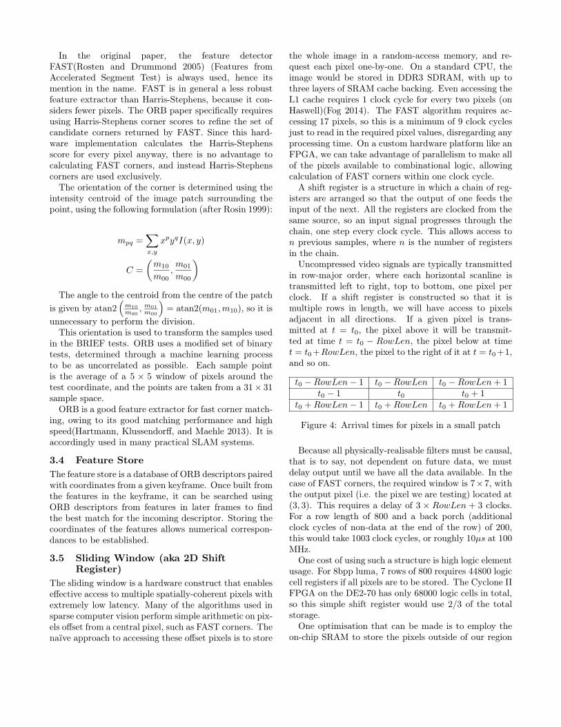
3 Components UsedThis section describes the components shown in 3 in de-tail.
Camera
Harris Cor-ner Detection
CornerThresholding
ORB FeatureExtractor
Feature Store
Correspondences
Figure 3: An overview of the data flow in the system.Blue blocks are I/O, orange blocks are processing andgreen blocks are storage.
3.1 Harris-Stephens Corner DetectionThe Harris corner metric was introduced in (Harris andStephens 1988) as a general corner detector. Calcula-tion of the metric takes approximately 18 times as longas FAST (see section 3.3) when implemented on CPU(Rosten and Drummond 2005), but in general providesbetter-quality features. The calculation looks at theeigenvalues of a Gaussian-filtered Harris matrix to de-termine a corner score. The terms of the Harris matrixare the outer product of the Sobel operator applied inthe x and y directions at the test point.
2www.rust-lang.org
H(x, y) =
[S2x Sx × Sy
Sy × Sx S2y
]H ′(x, y) = H(x, y) ∗Gk
R(x, y) = det(H ′)− kTr(H ′)
where H(x, y) is the Harris matrix, Gk is a discrete Gaus-sian filter kernel, k is a small (0.04 < k < 0.15) constant,and R is the cornerness score of the point. It is criticalto apply the Gaussian smoothing kernel, because the Hmatrix is always singular by construction. Harris givesa numerical score, rather than a binary yes/no, allowingcorner proposals to be sorted based on quality.
A further non-maximum suppression pass is usuallyapplied to Harris corners after the scores are calculated.This examines the 8 pixels surrounding the test pixel,and only reports the pixel as passing the test if its scoreis higher than those of the pixels around it. This ensuresthat only one pixel is chosen for each corner.
In general, the Harris algorithm provides more robustcorners than FAST, which are less sensitive to noise, andthus provide better results. The cost of using Harris overFAST is in computational complexity, meaning that itis generally not used as the first line feature detector inCPU implementations, but instead only used as a secondpass to select high quality corners from the candidatesreturned by FAST.
3.2 Corner ThresholdingThe Harris-Stephens corner detector returns a numericalcorner score for each corner it returns. This score repre-sents the algorithm’s confidence that the given point isin fact a corner, as opposed to a point along an edge ora point in the middle of a flat colour area. The cornerscore will be higher for corners with stronger contrast,for instance between white and black, than for cornerswith little contrast, such as between two different shadesof grey.
We can apply a threshold to these corner scores inorder to filter out low-quality corners and only retainpoints that are corners with high confidence. The choiceof the threshold is a tunable parameter of the system,with the exact value dependent on the contrast of theimage as a whole and the number of corners desired. Ifthe image is generally high-contrast, it may be necessaryto use a higher threshold value to ensure that the numberof output corners does not swamp the feature store.
3.3 ORB Feature ExtractorOriented FAST and Rotated BRIEF (ORB) was intro-duced in (Rublee et al. 2011) as a rotation-invariant de-velopment of BRIEF(Calonder et al. 2010). It achievesthis invariance by rotating the BRIEF sample mask ac-cording to the orientation of the corner.
In the original paper, the feature detectorFAST(Rosten and Drummond 2005) (Features fromAccelerated Segment Test) is always used, hence itsmention in the name. FAST is in general a less robustfeature extractor than Harris-Stephens, because it con-siders fewer pixels. The ORB paper specifically requiresusing Harris-Stephens corner scores to refine the set ofcandidate corners returned by FAST. Since this hard-ware implementation calculates the Harris-Stephensscore for every pixel anyway, there is no advantage tocalculating FAST corners, and instead Harris-Stephenscorners are used exclusively.
The orientation of the corner is determined using theintensity centroid of the image patch surrounding thepoint, using the following formulation (after Rosin 1999):
mpq =∑x,y
xpyqI(x, y)
C =
(m10
m00,m01
m00
)The angle to the centroid from the centre of the patch
is given by atan2(
m10
m00, m01
m00
)= atan2(m01,m10), so it is
unnecessary to perform the division.This orientation is used to transform the samples used
in the BRIEF tests. ORB uses a modified set of binarytests, determined through a machine learning processto be as uncorrelated as possible. Each sample pointis the average of a 5 × 5 window of pixels around thetest coordinate, and the points are taken from a 31× 31sample space.
ORB is a good feature extractor for fast corner match-ing, owing to its good matching performance and highspeed(Hartmann, Klussendorff, and Maehle 2013). It isaccordingly used in many practical SLAM systems.
3.4 Feature StoreThe feature store is a database of ORB descriptors pairedwith coordinates from a given keyframe. Once built fromthe features in the keyframe, it can be searched usingORB descriptors from features in later frames to findthe best match for the incoming descriptor. Storing thecoordinates of the features allows numerical correspon-dances to be established.
3.5 Sliding Window (aka 2D ShiftRegister)
The sliding window is a hardware construct that enableseffective access to multiple spatially-coherent pixels withextremely low latency. Many of the algorithms used insparse computer vision perform simple arithmetic on pix-els offset from a central pixel, such as FAST corners. Thenaïve approach to accessing these offset pixels is to store
the whole image in a random-access memory, and re-quest each pixel one-by-one. On a standard CPU, theimage would be stored in DDR3 SDRAM, with up tothree layers of SRAM cache backing. Even accessing theL1 cache requires 1 clock cycle for every two pixels (onHaswell)(Fog 2014). The FAST algorithm requires ac-cessing 17 pixels, so this is a minimum of 9 clock cyclesjust to read in the required pixel values, disregarding anyprocessing time. On a custom hardware platform like anFPGA, we can take advantage of parallelism to make allof the pixels available to combinational logic, allowingcalculation of FAST corners within one clock cycle.
A shift register is a structure in which a chain of reg-isters are arranged so that the output of one feeds theinput of the next. All the registers are clocked from thesame source, so an input signal progresses through thechain, one step every clock cycle. This allows access ton previous samples, where n is the number of registersin the chain.
Uncompressed video signals are typically transmittedin row-major order, where each horizontal scanline istransmitted left to right, top to bottom, one pixel perclock. If a shift register is constructed so that it ismultiple rows in length, we will have access to pixelsadjacent in all directions. If a given pixel is trans-mitted at t = t0, the pixel above it will be transmit-ted at time t = t0 − RowLen, the pixel below at timet = t0+RowLen, the pixel to the right of it at t = t0+1,and so on.
t0 −RowLen− 1 t0 −RowLen t0 −RowLen+ 1t0 − 1 t0 t0 + 1
t0 +RowLen− 1 t0 +RowLen t0 +RowLen+ 1
Figure 4: Arrival times for pixels in a small patch
Because all physically-realisable filters must be causal,that is to say, not dependent on future data, we mustdelay output until we have all the data available. In thecase of FAST corners, the required window is 7×7, withthe output pixel (i.e. the pixel we are testing) located at(3, 3). This requires a delay of 3 × RowLen + 3 clocks.For a row length of 800 and a back porch (additionalclock cycles of non-data at the end of the row) of 200,this would take 1003 clock cycles, or roughly 10µs at 100MHz.
One cost of using such a structure is high logic elementusage. For 8bpp luma, 7 rows of 800 requires 44800 logiccell registers if all pixels are to be stored. The Cyclone IIFPGA on the DE2-70 has only 68000 logic cells in total,so this simple shift register would use 2/3 of the totalstorage.
One optimisation that can be made is to employ theon-chip SRAM to store the pixels outside of our region
Input
3 × 3 SR
Harris Matrix
7 × 7 SR
Gaussian Filter
Harris Metric
3 × 3 SR
Non-maxSuppression
Output
8 bit
3× 3× 8 bit
2× 2× 16 bit
7× 7× 2× 2× 16 bit
2× 2× 16 bit
33 bit
3× 3× 33 bit
boolean
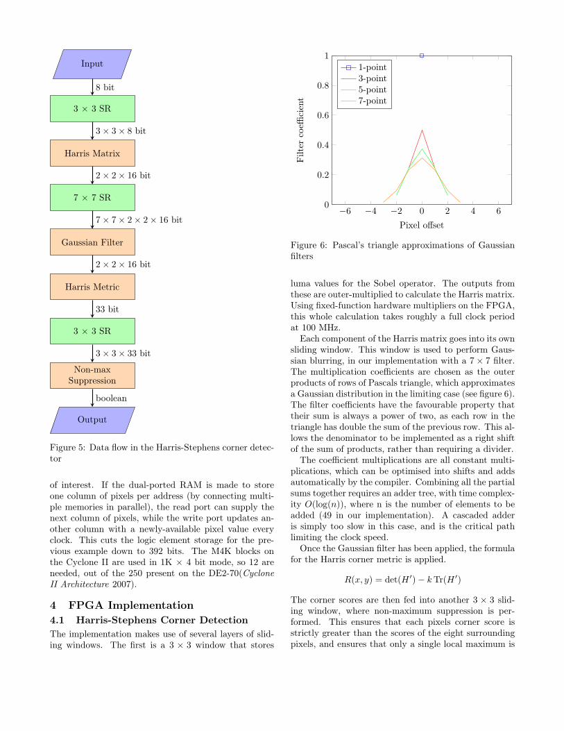
Figure 5: Data flow in the Harris-Stephens corner detec-tor
of interest. If the dual-ported RAM is made to storeone column of pixels per address (by connecting multi-ple memories in parallel), the read port can supply thenext column of pixels, while the write port updates an-other column with a newly-available pixel value everyclock. This cuts the logic element storage for the pre-vious example down to 392 bits. The M4K blocks onthe Cyclone II are used in 1K × 4 bit mode, so 12 areneeded, out of the 250 present on the DE2-70(CycloneII Architecture 2007).
4 FPGA Implementation4.1 Harris-Stephens Corner DetectionThe implementation makes use of several layers of slid-ing windows. The first is a 3 × 3 window that stores
−6 −4 −2 0 2 4 60
0.2
0.4
0.6
0.8
1
Pixel offset
Filt
erco
effici
ent
1-point3-point5-point7-point
Figure 6: Pascal’s triangle approximations of Gaussianfilters
luma values for the Sobel operator. The outputs fromthese are outer-multiplied to calculate the Harris matrix.Using fixed-function hardware multipliers on the FPGA,this whole calculation takes roughly a full clock periodat 100 MHz.
Each component of the Harris matrix goes into its ownsliding window. This window is used to perform Gaus-sian blurring, in our implementation with a 7× 7 filter.The multiplication coefficients are chosen as the outerproducts of rows of Pascals triangle, which approximatesa Gaussian distribution in the limiting case (see figure 6).The filter coefficients have the favourable property thattheir sum is always a power of two, as each row in thetriangle has double the sum of the previous row. This al-lows the denominator to be implemented as a right shiftof the sum of products, rather than requiring a divider.
The coefficient multiplications are all constant multi-plications, which can be optimised into shifts and addsautomatically by the compiler. Combining all the partialsums together requires an adder tree, with time complex-ity O(log(n)), where n is the number of elements to beadded (49 in our implementation). A cascaded adderis simply too slow in this case, and is the critical pathlimiting the clock speed.
Once the Gaussian filter has been applied, the formulafor the Harris corner metric is applied.
R(x, y) = det(H ′)− kTr(H ′)
The corner scores are then fed into another 3 × 3 slid-ing window, where non-maximum suppression is per-formed. This ensures that each pixels corner score isstrictly greater than the scores of the eight surroundingpixels, and ensures that only a single local maximum is
found for each corner.Any pixel that passes through the non-maximum sup-
pression, and is higher than a threshold value, is deter-mined to be a corner feature, and is displayed to thescreen by means of a pink mark drawn on several suc-cessive pixels, for ease of visual observation.
4.2 ORB Feature Extractor
Window
Image Centroid OrientationCalculation
CoordinateGenerator
Patch Sampler
Comparison
Descriptor
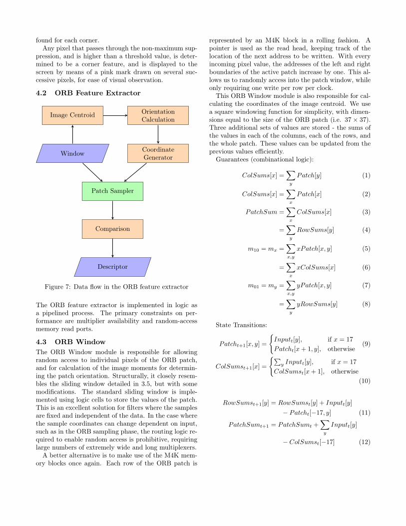
Figure 7: Data flow in the ORB feature extractor
The ORB feature extractor is implemented in logic asa pipelined process. The primary constraints on per-formance are multiplier availability and random-accessmemory read ports.
4.3 ORB WindowThe ORB Window module is responsible for allowingrandom access to individual pixels of the ORB patch,and for calculation of the image moments for determin-ing the patch orientation. Structurally, it closely resem-bles the sliding window detailed in 3.5, but with somemodifications. The standard sliding window is imple-mented using logic cells to store the values of the patch.This is an excellent solution for filters where the samplesare fixed and independent of the data. In the case wherethe sample coordinates can change dependent on input,such as in the ORB sampling phase, the routing logic re-quired to enable random access is prohibitive, requiringlarge numbers of extremely wide and long multiplexers.
A better alternative is to make use of the M4K mem-ory blocks once again. Each row of the ORB patch is
represented by an M4K block in a rolling fashion. Apointer is used as the read head, keeping track of thelocation of the next address to be written. With everyincoming pixel value, the addresses of the left and rightboundaries of the active patch increase by one. This al-lows us to randomly access into the patch window, whileonly requiring one write per row per clock.
This ORB Window module is also responsible for cal-culating the coordinates of the image centroid. We usea square windowing function for simplicity, with dimen-sions equal to the size of the ORB patch (i.e. 37 × 37).Three additional sets of values are stored - the sums ofthe values in each of the columns, each of the rows, andthe whole patch. These values can be updated from theprevious values efficiently.
Guarantees (combinational logic):
ColSums[x] =∑y
Patch[y] (1)
ColSums[x] =∑x
Patch[x] (2)
PatchSum =∑x
ColSums[x] (3)
=∑y
RowSums[y] (4)
m10 = mx =∑x,y
xPatch[x, y] (5)
=∑x
xColSums[x] (6)
m01 = my =∑x,y
yPatch[x, y] (7)
=∑y
yRowSums[y] (8)
State Transitions:
Patcht+1[x, y] =
{Inputt[y], if x = 17
Patcht[x+ 1, y], otherwise(9)
ColSumst+1[x] =
{∑y Inputt[y], if x = 17
ColSumst[x+ 1], otherwise(10)
RowSumst+1[y] = RowSumst[y] + Inputt[y]
− Patcht[−17, y] (11)
PatchSumt+1 = PatchSumt +∑y
Inputt[y]
− ColSumst[−17] (12)
mx,t+1 −mx,t =17∑
x=−17
x(Ct+1[x]− Ct[x])
= 17×∑y
Inputt[y]− PatchSumt
+ 18× Ct[−17] (13)
The various internal values are kept up to date withincoming pixel data, meaning that calculation of the im-age moments for image centroid computation requires noadditional time. Some logic can be saved by using deltavalues for calculating mx
Since row sum calculation involves subtraction of theoutgoing pixel as well as addition of the incoming pixel,we require two access ports on the memory. One is usedas a write head, writing the value of the incoming pixelinto the RAM, while the other is used as a read head,reading from the outgoing pixel. In random access op-eration mode, used when sampling the image patch togenerate bits of the descriptor, both ports are used asread ports to double the throughput.
4.4 Image CentroidThe first step in the calculation of the ORB descriptoris to determine the coordinates of the image centroid.The image centroid itself is not actually calculated, asthis would require a slow division operation. Instead, thetwo image moments m10 and m01 are output directly tothe orientation calculation step, which is only concernedwith the ratio between the moments.
The orientation calculation has the task of returningan approximation of atan2(m01,m10). Rublee et al. 2011suggests using 30 different angle quantisations, corre-sponding to a separation of 12◦, and a maximum er-ror in angle of 6◦. This number was chosen because itallowed for a reasonable number of coordinate lookup ta-bles in the original code. The code currently shipping inOpenCV, however, uses atan2 directly, allowing full pre-cision in the results. We elected not to implement atan2with a CORDIC unit in hardware, but instead to usea high-resolution approximation. 64 steps yield a maxi-mum error in angle of 2.81◦
(36064
). Considering the patch
is of radius 18 pixels, the maximum possible positionalerror is
18 sin
(2π
2× 64
)= 0.88 pixels (14)
This is similar in magnitude to the quantisation errorover the whole patch, and so is deemed to be acceptable.
The orientation is calculated using a lookup table. Thefirst two steps determine the quadrant of the angle basedon the signs of the two image moments. At the sametime, the vector of x and y positions is rotated so thatit is in the quadrant
[0, π
2
). Given the vector [x, y], the
angle θ is given by
tan(θ) =y
x, (15)
which can be manipulated to give
x tan(θ) = y, (16)
requiring no divisions. Since all of our 16 possible θvalues are known ahead of time, their tangents can beprecalculated. Their products with x are computed, andeach is tried in order, to find the angle that best matchesthe y value.
The coordinate generation step takes as inputs the ori-entation from the previous step and pairs of ORB com-parison sample coordinates. The sample points are withreference to an orientation of 0◦, so they must be vectorrotated to align with the feature in question. Since thenumber of possible orientations is relatively small, thesin and cos values are precalculated and used as entriesin a lookup table. Since both the sample coordinates andthe rotation angle change depending on inputs, hardwaremultipliers must be used for the vector rotation, and notjust shifts and adds. The coordinates of the samples aretransformed using[
x′
y′
]=
[cos(θ) − sin(θ)sin(θ) cos(θ)
] [xy
]. (17)
Once a pair of sample coordinates has been generated,these are used as indexes into the patch image to samplepixels for comparison. The ORB Window patches arestored in M4K block memory, and considering each blockhas two read ports, each copy of the image patch cansatisfy enough reads to generate one bit of descriptorper clock cycle.
The final step of the process is to compare the inten-sities of the two pixel samples returned from the patchsampler. If the first sample intensity is greater than thesecond, the descriptor bit is set, else it is reset. Onceall 256 bits of the ORB descriptor are determined, thedescriptor is returned for indexing.
4.5 Feature StoreThe ORB descriptors are stored in a specialised datastructure, along with their coordinates in the keyframeimage. Whenever a corner descriptor is calculated by theORB extractor, it flows through a FIFO (first-in, first-out) queue to the feature store module. If the framebeing processed is a keyframe, the descriptor and its co-ordinates are stored in the memory of the feature store.If the frame is a regular frame, instead of being stored,the descriptor is compared against all the features cur-rently in the store.
The comparison process is a simple brute-force lin-ear scan, with the best match defined as the compari-son that has the smallest Hamming distance. This ap-proach was chosen because it is guaranteed to yield thebest matching performance, since every possible matchis checked. Moreover, considering the hardware architec-ture, descriptor comparisons can be performed extremelycheaply, requiring only an xor operation and a bit pop-ulation count. They can also be parallelised effectively,allowing multiple comparisons to be performed per clockcycle.
4.6 ParallelismSince the processes of generating sample coordinates andsampling are independent for each pair of samples, thosesteps can very easily be parallelised. Calculating onepair of coordinates and performing one pair of samplesper clock would require 256 clocks to extract the wholedescriptor, while having four such operations runningin parallel would reduce the runtime to 64 clocks. Onthe development platform, each coordinate generationtakes 8 9-bit DSP multipliers, and each copy of the imagepatch takes 4 M4K memory blocks.
To enable this usage, the ORB Window module canbe instantiated multiple times for each ORB descriptormodule. Each instance receives the same input pixels,meaning that all have the same contents. When a cor-ner is detected, the input ceases, so that both ports areavailable for random access. Since the ORB Windowsare not taking input while they are being used for calcu-lation, any corners that occur between when the input isdetached and the point when the windows have reloadeda new frame are lost. To prevent such corners beingmissed, the entire ORB module can be duplicated. Anarbitrator manages the allocation of the ORB moduleresources to detected corners, selecting a free module foreach corner, provided one is available.
5 Differences from OpenCVimplementation
The standard reference implementation for the algo-rithms discussed in this paper is the OpenCV library.OpenCV includes Cuda- and OpenCV-accelerated ver-sions of the ORB feature extractor, suitable for runningon a GPU. Only a CPU version of the Harris-Stephenscorner detector is offered.
5.1 Harris-Stephens Corner DetectorThe reference implementation of the Harris-Stephenscorner detector is designed to run on standard computerhardware, and as such operates as a multi-pass opera-tion. The first pass calculates per-pixel corner scoresand caches them, while the second pass is used to filterthe corner scores. An example filtering scheme might
be to take the 200 highest scores, with the proviso thatno corner can be within 3 pixels of any other previous-selected corner.
This process requires caching all the corner scores inan image and sorting them, which is inefficient for amemory-constrained FPGA device. Instead, this worktakes a slightly different approach, where a hard thresh-old is used, and only points with a Harris-Stephens scoreover the threshold are accepted. The minimum distancebetween points is fixed at 2px, implemented with a 3×3window non-maximum suppression filter.
5.2 ORB Feature ExtractorThe primary difference between our implementation ofthe ORB feature extractor is in the resolution of the sam-ple orientation process. To speed up the calculation pro-cess, the orientation is constrained to steps of π
32 , insteadof allowing the full gamut of 32-bit floating point. Thiscan result in small misalignments of the sample mask,and yield slightly different descriptor values dependenton the rotation of the image patch.
6 Results
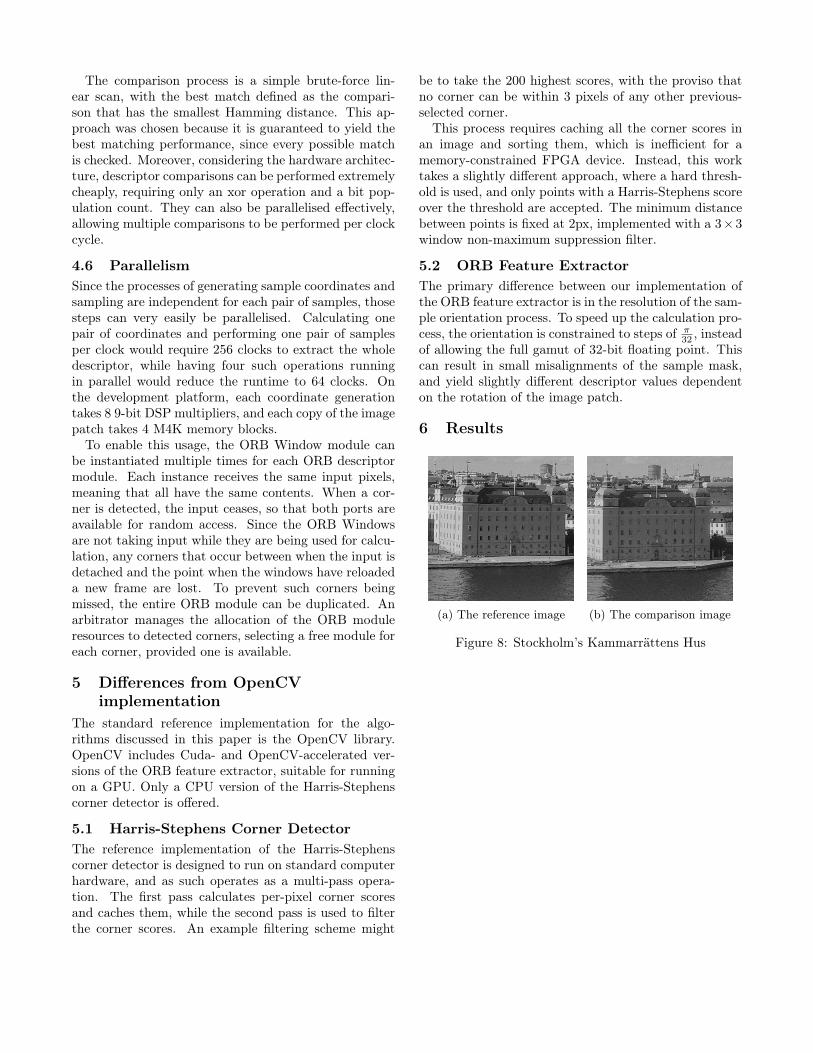
(a) The reference image (b) The comparison image
Figure 8: Stockholm’s Kammarrättens Hus
0 20 40 60 80 100 1200
0.2
0.4
0.6
0.8
1
Hamming distance threshold
Inlie
rpr
opor
tion
Inlier proportion at different match thresholds
SimulationOpenCV
0 50 100 150 2000
0.2
0.4
0.6
0.8
1
Match count
Inlie
rpr
opor
tion
Inlier proportion at different match counts
SimulationOpenCV
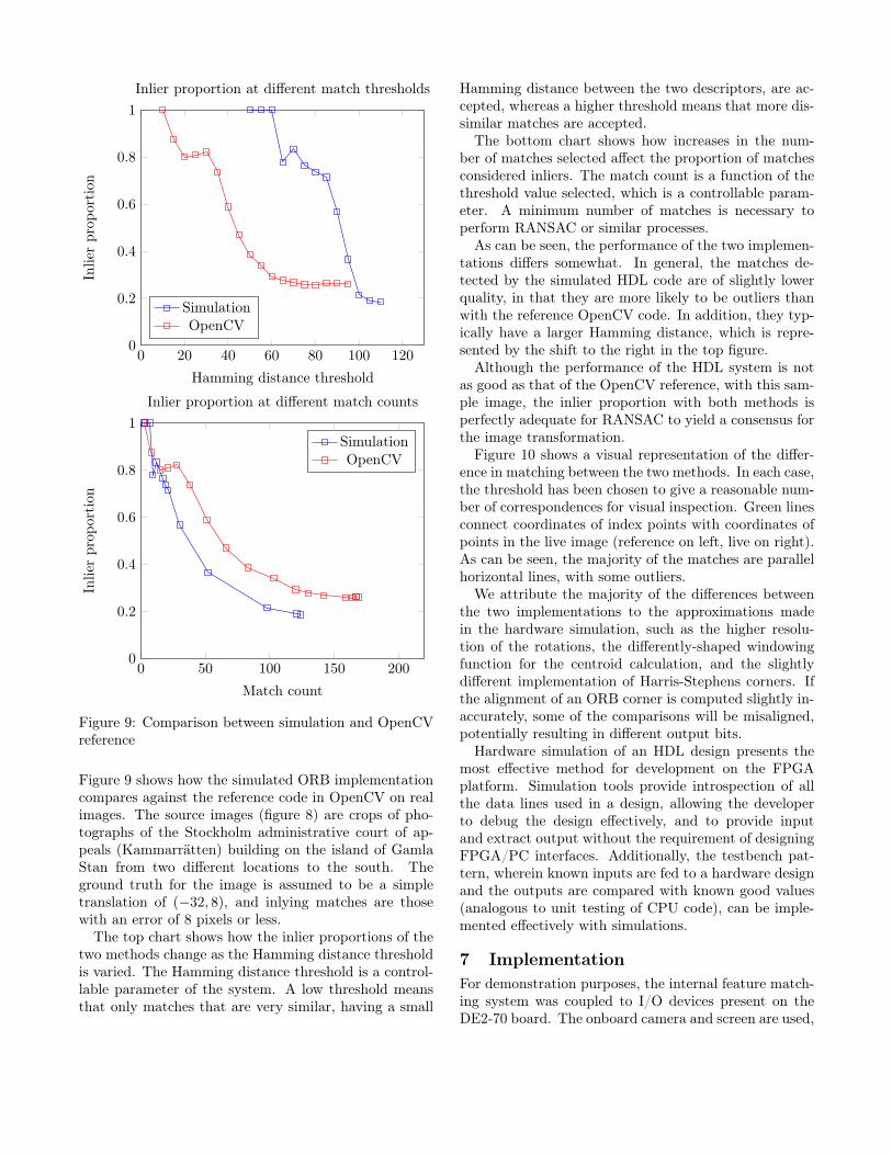
Figure 9: Comparison between simulation and OpenCVreference
Figure 9 shows how the simulated ORB implementationcompares against the reference code in OpenCV on realimages. The source images (figure 8) are crops of pho-tographs of the Stockholm administrative court of ap-peals (Kammarrätten) building on the island of GamlaStan from two different locations to the south. Theground truth for the image is assumed to be a simpletranslation of (−32, 8), and inlying matches are thosewith an error of 8 pixels or less.
The top chart shows how the inlier proportions of thetwo methods change as the Hamming distance thresholdis varied. The Hamming distance threshold is a control-lable parameter of the system. A low threshold meansthat only matches that are very similar, having a small
Hamming distance between the two descriptors, are ac-cepted, whereas a higher threshold means that more dis-similar matches are accepted.
The bottom chart shows how increases in the num-ber of matches selected affect the proportion of matchesconsidered inliers. The match count is a function of thethreshold value selected, which is a controllable param-eter. A minimum number of matches is necessary toperform RANSAC or similar processes.
As can be seen, the performance of the two implemen-tations differs somewhat. In general, the matches de-tected by the simulated HDL code are of slightly lowerquality, in that they are more likely to be outliers thanwith the reference OpenCV code. In addition, they typ-ically have a larger Hamming distance, which is repre-sented by the shift to the right in the top figure.
Although the performance of the HDL system is notas good as that of the OpenCV reference, with this sam-ple image, the inlier proportion with both methods isperfectly adequate for RANSAC to yield a consensus forthe image transformation.
Figure 10 shows a visual representation of the differ-ence in matching between the two methods. In each case,the threshold has been chosen to give a reasonable num-ber of correspondences for visual inspection. Green linesconnect coordinates of index points with coordinates ofpoints in the live image (reference on left, live on right).As can be seen, the majority of the matches are parallelhorizontal lines, with some outliers.
We attribute the majority of the differences betweenthe two implementations to the approximations madein the hardware simulation, such as the higher resolu-tion of the rotations, the differently-shaped windowingfunction for the centroid calculation, and the slightlydifferent implementation of Harris-Stephens corners. Ifthe alignment of an ORB corner is computed slightly in-accurately, some of the comparisons will be misaligned,potentially resulting in different output bits.
Hardware simulation of an HDL design presents themost effective method for development on the FPGAplatform. Simulation tools provide introspection of allthe data lines used in a design, allowing the developerto debug the design effectively, and to provide inputand extract output without the requirement of designingFPGA/PC interfaces. Additionally, the testbench pat-tern, wherein known inputs are fed to a hardware designand the outputs are compared with known good values(analogous to unit testing of CPU code), can be imple-mented effectively with simulations.
7 ImplementationFor demonstration purposes, the internal feature match-ing system was coupled to I/O devices present on theDE2-70 board. The onboard camera and screen are used,
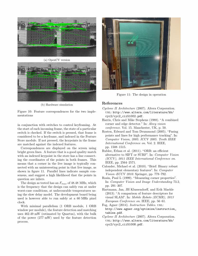
(a) OpenCV version
(b) Hardware simulation
Figure 10: Feature correspondences for the two imple-mentations
in conjunction with switches to control keyframing. Atthe start of each incoming frame, the state of a particularswitch is checked. If the switch is pressed, that frame isconsidered to be a keyframe, and indexed in the FeatureStore module. If not pressed, the keypoints in the frameare matched against the indexed features.
Correspondences are displayed on the screen usingbright green lines. A feature that is a good quality matchwith an indexed keypoint in the store has a line connect-ing the coordinates of the points in both frames. Thismeans that a corner in the live image is typically con-nected with an uninteresting point in that live image, asshown in figure 11. Parallel lines indicate sample con-sensus, and suggest a high likelihood that the points inquestion are inliers.
The design as tested has an Fmax of 48.48 MHz, whichis the frequency that the design can safely run at underworst-case conditions, at unfavourable temperatures us-ing the slow delay model. The development board beingused is however able to run safely at a 60 MHz pixelclock.
With minimal parallelism (1 ORB module, 1 ORBwindow per module), the feature detection and matchinguses 462.49 mW (estimated by Quartus), with the bulkof the power (277 mW) used by the feature detectionprocess.
Figure 11: The design in operation
ReferencesCyclone II Architecture (2007). Altera Corporation.
url: http://www.altera.com/literature/hb/cyc2/cyc2_cii51002.pdf.
Harris, Chris and Mike Stephens (1988). “A combinedcorner and edge detector.” In: Alvey visionconference. Vol. 15. Manchester, UK, p. 50.
Rosten, Edward and Tom Drummond (2005). “Fusingpoints and lines for high performance tracking”. In:Computer Vision, 2005. ICCV 2005. Tenth IEEEInternational Conference on. Vol. 2. IEEE,pp. 1508–1515.
Rublee, Ethan et al. (2011). “ORB: an efficientalternative to SIFT or SURF”. In: Computer Vision(ICCV), 2011 IEEE International Conference on.IEEE, pp. 2564–2571.
Calonder, Michael et al. (2010). “Brief: Binary robustindependent elementary features”. In: ComputerVision–ECCV 2010. Springer, pp. 778–792.
Rosin, Paul L (1999). “Measuring corner properties”.In: Computer Vision and Image Understanding 73.2,pp. 291–307.
Hartmann, Jan, JH Klussendorff, and Erik Maehle(2013). “A comparison of feature descriptors forvisual SLAM”. In: Mobile Robots (ECMR), 2013European Conference on. IEEE, pp. 56–61.
Fog, Agner (2014). Instruction Tables. url:http://www.agner.org/optimize/instruction_
tables.pdf.Cyclone II Architecture (2007). Altera Corporation.
url: http://www.altera.com/literature/hb/cyc2/cyc2_cii51008.pdf.
Related Documents