381333–230 C 50 Hanover Road, Florham Park, New Jersey 07932–1591 USA For sales or service call 1 800 800–2726 (ASCO) www.ascopower.com ASCO POWER TECHNOLOGIES CANADA PO Box 1238, 17 Airport Road, Brantford, Ontario, Canada N3T 5T3 telephone 519 758–8450, fax 519 758–0876, for service call 1 888 234–2726 (ASCO) www.asco.ca Operator’s Manual Series 386 Electrically–Operated Non–Automatic Transfer Switches D–design 30 through 230 amps DANGER is used in this manual to warn of high voltages capable of causing shock, burns, or death. WARNING is used in this manual to warn of possible personal injury. CAUTION is used in this manual to warn of possible equipment damage. 30–200 amp sizes Note: Refer to the outline and wiring drawings provided with your ASCO Series 386 Non–Automatic Transfer Switch for all installation and connection details and accessories. An experienced licensed electrician must install the Non- Automatic Transfer Switch. Rating Label Each Non-Automatic Transfer Switch contains a rating label to define the loads and fault circuit withstand/closing ratings. Refer to the label on the Transfer Switch for specific values. Do not exceed the values on the rating label. Exceeding the rating can cause personal injury or serious equipment damage. Identification Label The identification label on the Transfer Switch includes data for each specific ASCO Series 386. Use the switch only within the limits shown on identification label. TABLE OF CONTENTS INSTALLATION 1-1 ........................ Functional Test 1-2 ........................ SEQUENCE OF OPERATION 2-1 ........... TESTING & SERVICE 3-1 .................. Troubleshooting 3-2 ....................... ADJUSTMENTS 4-1 ....................... OPTIONAL FEATURES 5-1 ................. INDEX back cover .........................

Welcome message from author
This document is posted to help you gain knowledge. Please leave a comment to let me know what you think about it! Share it to your friends and learn new things together.
Transcript

381333–230 C50 Hanover Road, Florham Park, New Jersey 07932–1591 USAFor sales or service call 1 800 800–2726 (ASCO) www.ascopower.com
ASCO POWER TECHNOLOGIES CANADA PO Box 1238, 17 Airport Road, Brantford, Ontario, Canada N3T 5T3telephone 519 758–8450, fax 519 758–0876, for service call 1 888 234–2726 (ASCO) www.asco.ca
Operator’sManual
Series 386 Electrically–OperatedNon–Automatic Transfer SwitchesD–design 30 through 230 amps
DANGER is used in this manual to warn of highvoltages capable of causing shock, burns, or death.
WARNING is used in this manual to warnof possible personal injury.
CAUTION is used in this manual to warnof possible equipment damage.
30–200 amp sizes
Note: Refer to the outline and wiring drawingsprovidedwith yourASCOSeries 386Non–AutomaticTransfer Switch for all installation and connectiondetails and accessories.
An experienced licensed electrician must install the Non-Automatic Transfer Switch.
Rating LabelEach Non-Automatic Transfer Switch contains a rating labelto define the loads and fault circuit withstand/closing ratings.Refer to the label on the Transfer Switch for specific values.
Do not exceed the values on the rating label.Exceeding the rating can cause personal injury
or serious equipment damage.
Identification LabelThe identification label on the Transfer Switch includesdata for each specificASCOSeries 386. Use the switch onlywithin the limits shown on identification label.
TABLE OF CONTENTS
INSTALLATION 1-1. . . . . . . . . . . . . . . . . . . . . . . .Functional Test 1-2. . . . . . . . . . . . . . . . . . . . . . . .SEQUENCE OF OPERATION 2-1. . . . . . . . . . .
TESTING & SERVICE 3-1. . . . . . . . . . . . . . . . . .Troubleshooting 3-2. . . . . . . . . . . . . . . . . . . . . . .ADJUSTMENTS 4-1. . . . . . . . . . . . . . . . . . . . . . .OPTIONAL FEATURES 5-1. . . . . . . . . . . . . . . . .
INDEX back cover. . . . . . . . . . . . . . . . . . . . . . . . .
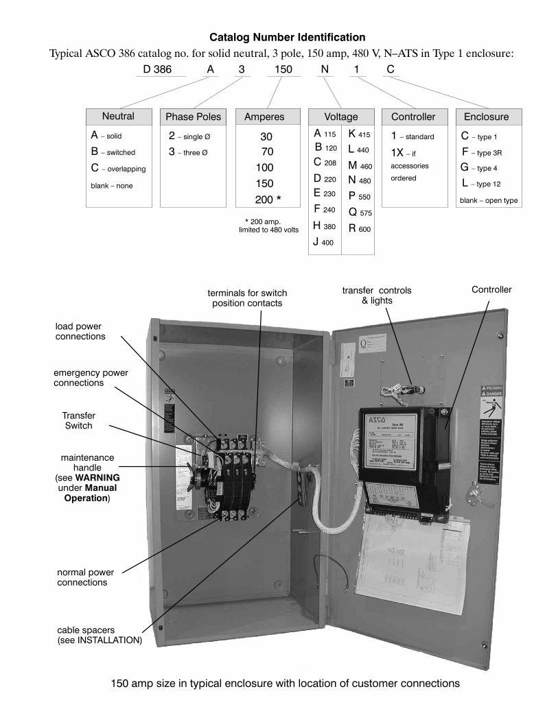
Catalog Number IdentificationTypical ASCO 386 catalog no. for solid neutral, 3 pole, 150 amp, 480 V, N–ATS in Type 1 enclosure:
D 386 A 3 150 N 1 C
Phase PolesNeutral
A – solid
C – overlapping
Amperes Voltage Controller Enclosure
B – switched
1 – standard
G – type 4
C – type 1
F – type 3R
L – type 12
3 – three Ø
2 – single Ø
D 220
C 208
E 230
K 415
M 460
J 400
L 440
N 480
F 240
H 380
Q 575
P 550
R 600
15010070
blank – none
blank – open type
301X – if
accessories
ordered
200 *
B 120
A 115
* 200 amp.limited to 480 volts
150 amp size in typical enclosure with location of customer connections
TransferSwitch
Controller
normal powerconnections
emergency powerconnections
transfer controls& lights
terminals for switchposition contacts
load powerconnections
cable spacers(see INSTALLATION)
maintenancehandle
(see WARNINGunder ManualOperation)
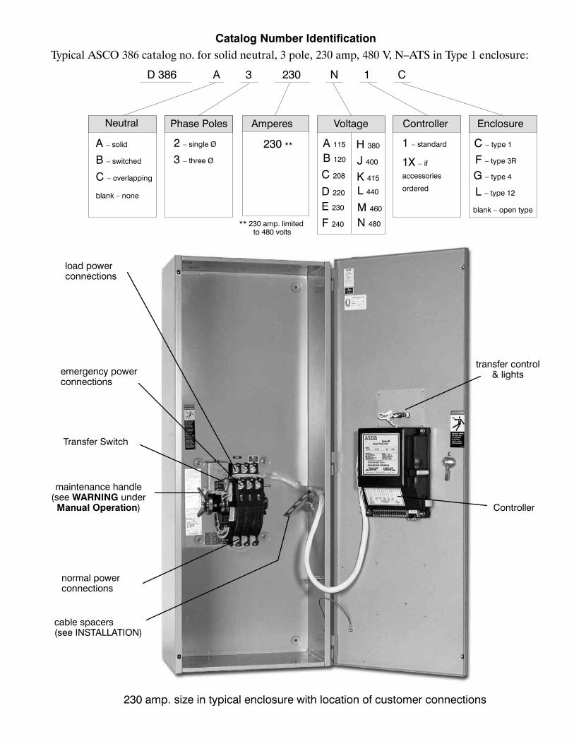
Catalog Number IdentificationTypical ASCO 386 catalog no. for solid neutral, 3 pole, 230 amp, 480 V, N–ATS in Type 1 enclosure:
D 386 A 3 230 N 1 C
Phase PolesNeutral Amperes Voltage Controller Enclosure
1 – standard
G – type 4
C – type 1
F – type 3R
L – type 12
3 – three Ø
2 – single Ø
D 220
C 208
E 230
K 415
M 460
J 400
L 440
N 480F 240
H 380230 **
blank – open type
1X – if
accessories
ordered
** 230 amp. limitedto 480 volts
A 115
B 120
A – solid
C – overlapping
B – switched
blank – none
230 amp. size in typical enclosure with location of customer connections
Transfer Switch
Controller
normal powerconnections
emergency powerconnections
transfer control& lights
load powerconnections
cable spacers(see INSTALLATION)
maintenance handle(see WARNING underManual Operation)
SECTION 1 INSTALLATION
1---1
ASCO386Non–AutomaticTransfer Switches are factorywired and tested. Installation requires skid removal thensecuring the enclosure to the supporting foundation.
Mounting
Refer to the applicable enclosure outline drawing fur-nished with this switch and mount the Series 300according to details and instructions shown on diagram.
Line Connections
Refer to the Wiring Diagram provided with your ASCO386 N–ATS. All wiring must be made in accordance withthe National Electrical Code and local codes.
It is unnecessary to remove pole covers from the transferswitch. If you do remove them, reinstall them carefully.
De–energize the conductors before making anyline or auxiliary circuitry connections. Be surethat Normal and Emergency line connectionsare in proper phase rotation. Place engine gen-erator starting control in theOFF position. Makesure engine generator is not in operation.
Protect the non–automatic transfer switch fromconstruction grit and metal chips to preventmalfunction or shortened life of the N–ATS.
Connecting Power Conductors
After the power cables have been tested, connect them tothe appropriate terminal lugs on the transfer switch asshown on the wiring diagram provided with this ASCO386. Make sure the lugs providedare suitable for usewiththe cables being installed. Standard terminal lugs aresolderless screw type and will accept the wire sizes listedon the drawings providedwith theASCO 386. Be carefulwhen stripping insulation from the cables; avoid nickingor ringing the conductor. Remove surface oxides fromcables by cleaning with a wire brush. When aluminumcable is used, apply joint compound to conductors.Tighten cable lugs to the torque specified on rating label.
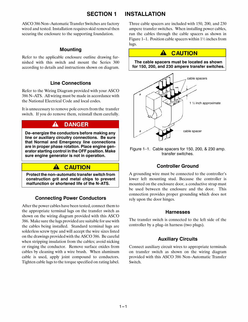
Three cable spacers are included with 150, 200, and 230ampere transfer switches. When installing power cables,run the cables through the cable spacers as shown inFigure 1–1. Position cable spacers within 1½ inches fromlugs.
The cable spacers must be located as shownfor 150, 200, and 230 ampere transfer switches.
cable spacer
cable spacers
1 ½ inch approximate
Figure 1–1. Cable spacers for 150, 200, & 230 amp.transfer switches.
Controller Ground
A grounding wire must be connected to the controller’slower left mounting stud. Because the controller ismounted on the enclosure door, a conductive strap mustbe used between the enclosure and the door. Thisconnection provides proper grounding which does notrely upon the door hinges.
Harnesses
The transfer switch is connected to the left side of thecontroller by a plug–in harness (two plugs).
Auxiliary Circuits
Connect auxiliary circuit wires to appropriate terminalson transfer switch as shown on the wiring diagramprovided with this ASCO 386 Non–Automatic TransferSwitch.

INSTALLATION (continued)
1---2
Functional TestThe Functional Test consists of three checks: manualoperation, voltage checks, and electrical operation.
Do these checks in the order presented to avoiddamaging the non–automatic transfer switch.
Read all instructions on the Wiring Diagram and labelsaffixed to the automatic transfer switch. Note the controlfeatures that are provided and review their operationbefore proceeding.
1 – Manual Operation Test
A maintenance handle is provided on the Transfer Switchfor maintenance purposes only. Manual operation of thetransfer switch should be checked before it is energized(operated electrically).
Do not manually operate the transfer switchuntil both power sources are disconnected:
open both circuit breakers.
1. After deenergizing both power sources, open theenclosure door. Locate and themaintenance handleon the left side of the transfer switch frame. SeeFigure 1–2.
2. Grasp the attached maintenance handle and turn itwith thumb and fingers as shown to manually operateit. The maintenance handle turns the opposite direc-tion of the weight. Move it up or down as shown tomanually operate the transfer switch. It should operatesmoothly without any binding. If it does not, check forshipping damage or construction debris.
3. Return the transfer switch to the Normal position.
Note: If Normal and Emergency connections arereversed this operation is also reversed.
Now continue to 2 – Voltage Checks on next page.
maintenancehandle
With ALL POWER OFF graspmaintenance handle and turn it
quickly with your thumb and fingers.
weight marked N (normal)and E (emergency)
floatingweight
weight
Position of the transfer switch is indicated here
Figure 1–2. Maintenance handle and positions.
INSTALLATION (continued)
1---3
Functional Test (continued)
2 – Voltage ChecksFirst check nameplate on the transfer switch for ratedvoltage. It should be the same as the normal andemergency line voltages.
Use extreme caution when using a meterto measure voltages in the followingsteps. Do not touch power terminals;shock, burns, or death could result !
1. Close the normal source circuit breaker. The LoadConnected To Normal lamp should come on.
2. Use an accurate voltmeter to check phase to phaseand phase to neutral voltages present at the TransferSwitch normal source terminals.
3. Close the emergency source circuit breaker. (Startthe generator, if necessary.)
4. Use an accurate voltmeter to check phase to phaseand phase to neutral voltages present at the TransferSwitch emergency source terminals.
If necessary, adjust the voltage regulator on the genera-tor according to the manufacturer’s recommendations.The ASCO 386 will respond only to the rated voltagespecified on the Transfer Switch nameplate.
5. Check phase rotation; it must be the same as thenormal source.
6. Shut down engine-driven generator, if applicable.
7. Close the cabinet door and tighten the screws.
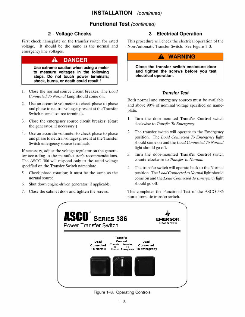
3 – Electrical OperationThis procedure will check the electrical operation of theNon-Automatic Transfer Switch. See Figure 1–3.
Close the transfer switch enclosure doorand tighten the screws before you testelectrical operation.
Transfer Test
Both normal and emergency sources must be availableand above 90% of nominal voltage specified on name-plate.
1. Turn the door-mounted Transfer Control switchclockwise to Transfer To Emergency.
2. The transfer switch will operate to the Emergencyposition. The Load Connected To Emergency lightshould come on and the Load Connected To Normallight should go off.
3. Turn the door-mounted Transfer Control switchcounterclockwise to Transfer To Normal.
4. The transfer switch will operate back to the Normalposition. TheLoadConnected toNormal light shouldcome on and theLoad Connected To Emergency lightshould go off.
This completes the Functional Test of the ASCO 386non-automatic transfer switch.
Figure 1–3. Operating Controls.
SECTION 2SEQUENCE OF OPERATION
2---1
Controller Code 1Refer to Section 5, Optional Accessories for additional control functions.
Refer toWiringDiagram furnishedwith theASCO386. NoteControl Features furnished on this switch, and review operation.
TransferControl
TransferTo
Normal
TransferTo
Emergency
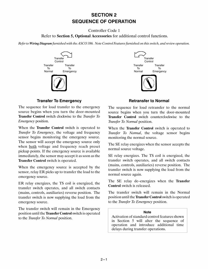
Transfer To EmergencyThe sequence for load transfer to the emergencysource begins when you turn the door-mountedTransfer Control switch clockwise to the Transfer ToEmergency position.
When the Transfer Control switch is operated toTransfer To Emergency, the voltage and frequencysensor begins monitoring the emergency source.The sensor will accept the emergency source onlywhen both voltage and frequency reach presetpickup points. If the emergency source is availableimmediately, the sensor may accept it as soon as theTransfer Control switch is operated.
When the emergency source is accepted by thesensor, relay ER picks up to transfer the load to theemergency source.
ER relay energizes, the TS coil is energized, thetransfer switch operates, and all switch contacts(mains, controls, auxiliaries) reverse position. Thetransfer switch is now supplying the load from theemergency source.
The transfer switch will remain in the Emergencyposition until theTransferControl switch is operatedto the Transfer To Normal position.
TransferControl
TransferTo
Normal
TransferTo
Emergency
Retransfer to Normal
The sequence for load retransfer to the normalsource begins when you turn the door-mountedTransfer Control switch counterclockwise to theTransfer To Normal position.
When the Transfer Control switch is operated toTransfer To Normal, the voltage sensor beginsmonitoring the normal source.
The SE relay energizes when the sensor accepts thenormal source voltage.
SE relay energizes. The TS coil is energized, thetransfer switch operates, and all switch contacts(mains, controls, auxiliaries) reverse position. Thetransfer switch is now supplying the load from thenormal source again.
The SE relay de–energizes when the TransferControl switch is released.
The transfer switch will remain in the Normalpositionuntil theTransferControl switch is operatedto the Transfer To Emergency position.
NoteActivation of standard control features shownin Section 5 will alter the sequence ofoperation and introduce additional timedelays during transfer operations.
SECTION 3TESTING & SERVICE
3---1
PREVENTIVE MAINTENANCEReasonable care in preventive maintenance will insurehigh reliability and long life for the switch. An annualpreventive maintenance program is recommended.
ASCO Services, Inc. (ASI) is ASCO PowerTechnologies’s national service organization. ASIcan be contacted at 1-800-800-2726 for informationon preventive maintenance agreements. InCanadacall 1–888–234–ASCO (2726).
TESTING
Operate the switch at least once amonth by following thisfour-step Electrical Operation Test.
Transfer Switch Test
A. Turn the door-mounted Transfer Control switchclockwise to Transfer to Emergency.
B. The transfer switch will operate to the Emergencyposition. The Load Connected To Emergency lightshould come on and the Load Connected to Normallight should go off.
C. Turn the door-mounted Transfer Control switchcounterclockwise to Transfer to Normal.
D. The transfer switch will operate to the Normal posi-tion. TheLoadConnected toNormal light should comeon and the Load Connected to Emergency light shouldgo off.
Checklist for Yearly Inspection
Hazardous voltage capable of causing shock,burns, or death is used in this switch.
Deenergize both Normal & Emergency powersources before performing inspections!
❐ Clean the switch enclosure. Brush and vacuum awayany excessive dust accumulation. Remove any mois-ture with a clean cloth.
❐ Check the Switch Contacts. Remove transfer switchbarriers and check the condition of the contacts. Re-place contacts when pitted or worn excessively. Re-install barriers carefully.
❐ Maintain transfer switch lubrication. If switch issubjected to severe dust or abnormal operating con-ditions, renew factory lubrication on all movementsand linkages. Relubricate solenoid operator if TScoil is replaced. Don’t use oil; order lubrication625550–001 (Castrol EndurexR 4000 lubricant).
❐ Check all cable connections and retighten them.
REPLACEMENT PARTS
Replacement parts are available in kit form. When or-dering parts provide the Serial No., Bill of Material No.(BOM), and Catalog No. from the transfer switch name-plate. Contact your local ASCO Power Technologiessales office or ASI. In the United States call1–800–800–ASCO (2726), or in Canada call1–888–234–ASCO (2726).
DISCONNECTING THE CONTROLLER
The harness disconnect plugs are furnished for repairpurposes only and should not have to be unplugged. Ifthe controller must be isolated, follow these steps:
Disconnecting the Plugs
Do not unplug the controller untilstep 1a. or 1b. below is completed.
1. Observe the position of the transfer switch.a. If the transfer switch is in theNormal position, place
standby engine starting control in the off position.Then open the emergency source circuit breaker.
b. If the transfer switch is in theEmergency position,open the normal source circuit breaker. Place theengine starting control in the test or run position.
2. Separate the quick disconnect plugs by squeezing thelatches. Do not pull on the harness wires.
Reconnecting the Plugs
Do not reconnect controller untilsteps 1 and 2 below are completed.
1. Observe the position of the transfer switch.
a. If the transfer switch is in theNormal position, besure that the standby engine starting control isstill in the offposition. The emergency source cir-cuit breaker still should be open.
b. If transfer switch is in the Emergency position, nor-mal source circuit breaker still should be open.
2. The harness plugs and sockets are keyed. Carefullyalign the plugs with the sockets and press straight inuntil both latches click.
3. Restore the opposite source as follows:
a. If the transfer switch is in the Normal position,place the standby engine starting control in theautomatic position. Then close the emergencysource circuit breaker.
b. If the transfer switch is in theEmergency position,close the normal source circuit breaker.

TESTING & SERVICE(continued)
3---2
MANUAL LOAD TRANSFERThis procedure will manually transfer the load if theController is disconnected.
Do not manually operate the transfer switchuntil both power sources are disconnected.
1. Open normal and emergency source circuit breakers.
2. Use manual handle to manually operate transferswitch to the opposite source. If detachable, removethe handle. See Section 1, Manual Operation.
3. If the transfer switch is in the Emergency positionmanually start the engine generator and then closethe emergency source circuit breaker.
TROUBLE-SHOOTING
Note theControl Features that are activated or furnishedon the switch and review their operation. Refer toSection 5, Optional Features.
Proceed with care! The ASCO 386 is energized.
Table 3-1. Trouble-Shooting Checks.
PROBLEMCHECK IN NUMERICAL SEQUENCE
PROBLEM 1 OPERATION 2 VOLTAGETransfer switch does nottransfer the load to theemergency source.
Turn Transfer Control switch clockwise toTransfer to Emergency position.
Generator ouput circuit breaker must beclosed. Voltmeter should read at least 90%of nominal phase to phase voltage betweentransfer switch terminals EA and EC(or EL1 and EL2 for 2 pole switches). *Generator frequency must be at least 57 Hz. *
* These are factory settings.
Transfer switch does nottransfer the load to the normalsource.
Turn Transfer Control switch counterclock-wise to Transfer to Normal position.
Voltmeter should read at least 90% of nominalphase to phase voltage between transfer switchterminals NB and NC, NC and NA,and NA and NB (or NL1 and NL2 for 2 poleswitches).
Trouble-Shooting Motor Load Transfer (Optional Feature 27) (refer to page 5-1)
Use extreme caution when using a meterto measure voltages in the followingsteps. Do not touch power terminals;shock, burns, or death could result !
1. Connect a voltmeter (set for twice systemphase-to-phase voltage) between Transfer Switchterminals NA and EA.
2. Manually start generator. Voltmeter needle shouldsweep back and forth at a regular rate between 0 andabout twice system voltage.
3. Turn the TRANSFER TO EMERGENCY controlswitch clockwise. The load should transfer toemergency source when meter needle is near 0 volts.If transfer does not occur, the Motor Load Transferaccessory is not operating.
4. Turn the TRANSFER TONORMAL control switchcounterclockwise. The load should retransfer backto the normal source when the needle is near 0 volts.If retransfer does not occur after the time delay, theMotor Load Transfer accessory is not operating.
5. Disconnect the voltmeter.
If theproblemis isolated to circuits on the controlleror the transfer switch, call your localASCOPowerTechnologiessales office or ASI. In the United States, call 1–800–800–2726. In Canada, call 1–888–234–2726. Furnish the SerialNo., Bill of Material (BOM) No., & Catalog No. from transfer switch nameplate.
SECTION 4 ADJUSTMENTS
4---1
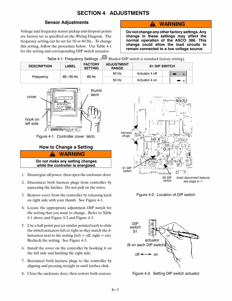
Sensor Adjustments
Voltage and frequency sensor pickup and dropout pointsare factory set as specified on the Wiring Diagram. Thefrequency setting can be set for 50 or 60 Hz.. To changethis setting, follow the procedure below. Use Table 4-1for the setting and corresponding DIP switch actuator.
Donot changeany other factory settings. Anychange in these settings may affect thenormal operation of the ASCO 386. Thischange could allow the load circuits toremain connected to a low voltage source.
Table 4-1. Frequency Settings. ( Shaded DIP switch is standard factory setting).
DESCRIPTION LABEL FACTORYSETTING
ADJUSTMENTRANGE S1 DIP SWITCH
Frequency 60 / 50 Hz 60 Hz60 Hz Actuator 4 off 4
Frequency 60 / 50 Hz 60 Hz50 Hz Actuator 4 on 4
thumblatchcover
hook onleft side
Figure 4-1. Controller cover latch.
How to Change a Setting
Do not make any setting changeswhile the controller is energized.
1. Deenergize all power, then open the enclosure door.
2. Disconnect both harness plugs from controller bysqueezing the latches. Do not pull on the wires.
3. Remove cover from the controller by releasing latchon right side with your thumb. See Figure 4-1.
4. Locate the appropriate adjustment DIP switch forthe setting that you want to change. Refer to Table4-1 above and Figure 4-2 and Figure 4-3.
5. Use a ball-point pen (or similar pointed tool) to slidethe switch actuators left or right so they match the il-lustration next to the setting (left = off, right = on).Recheck the setting. See Figure 4-3.
6. Install the cover on the controller by hooking it onthe left side and latching the right side.
7. Reconnect both harness plugs to the controller byaligning and pressing straight in until latches click.
8. Close the enclosure door, then restore both sources.
harnessplugs
S1 DIPswitch
S2 DIPswitch
(load disconnect feature)see page 5---1
Figure 4-2. Location of DIP switch.
DIPswitchS1
actuator
onoff
(8 on each DIP switch)
Figure 4-3. Setting DIP switch actuator.
SECTION 5 OPTIONAL FEATURES
5---1
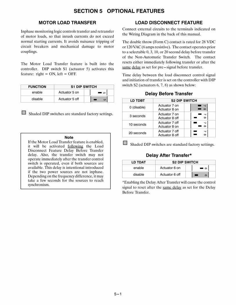
MOTOR LOAD TRANSFER
Inphase monitoring logic controls transfer and retransferof motor loads, so that inrush currents do not exceednormal starting currents. It avoids nuisance tripping ofcircuit breakers and mechanical damage to motorcouplings.
The Motor Load Transfer feature is built into thecontroller. DIP switch S1 (actuator 5) activates thisfeature: right = ON, left = OFF.
FUNCTION S1 DIP SWITCH
enable Actuator 5 on 5
disable Actuator 5 off 5
Shaded DIP switches are standard factory settings.
If theMotor Load Transfer feature is enabled,it will be activated following the LoadDisconnect Feature Delay Before Transferdelay. Also, the transfer switch may notoperate immediately after the transfer controlswitch is operated, even if both sources areavailable. This delay is intentional introducedif the two power sources are not inphase.Depending on the frequencydifference, itmaytake a few seconds for the sources to reachsynchronism.
Note
LOAD DISCONNECT FEATUREConnect external circuits to the terminals indicated onthe Wiring Diagram in the back of this manual.
The double throw (Form C) contact is rated for 28 VDCor120VAC(6amps resistive). The contact operatespriorto a selectable 0, 3, 10, or 20 second delay before transferof the Non-Automatic Transfer Switch. The contactresets either immediately following transfer or after thesame delay as set for pre---signal before transfer.
Time delay between the load disconnect control signaland initiation of transfer is set on the controller with DIPswitch S2 (actuators 6, 7, 8) as shown below:
Delay Before TransferLD TDBT S2 DIP SWITCH
0 (disable) Actuator 7 onActuator 8 on
87
3 seconds Actuator 7 onActuator 8 off
87
10 seconds Actuator 7 offActuator 8 on
87
20 seconds Actuator 7 offActuator 8 off
87
Shaded DIP switches are standard factory settings.
Delay After Transfer*LD TDAT S2 DIP SWITCH
enable Actuator 6 on 6
disable Actuator 6 off 6
*Enabling the Delay After Transfer will cause the controlsignal to reset after the same delay as set for the DelayBefore Transfer.

INDEX
Printed in U.S.A. Copyright --- ASCO Power Technologies, L.P. 2007
Aauxiliary circuits, 1–2
Bbarriers, 1–2
Ccablelugs, 1–1preparation, 1–1spacers, 1–1illustration of, 1–1
catalog number, inside cover
cleaning, 3–1
connectionsline, 1–1
controllercover removal, 4–1disconnecting, 3–1
DDIP Switches, 4–1, 5–1
Eelectrical operation, 1–3
Ffrequency, 50 or 60 Hz setting, 4–1
functional test, 1–2, 1–3
Hharness, 1–1disconnect plugs, 3–1
HELP800–800–2726 (ASCO)[email protected]
I
identification label, cover
inphase monitor, 5–1
inspection, 3–1
installation, 1–1
L
labels,rating, cover
lights, 1–3, 3–1
load connected to emergency, 1–3,3–1
load connected to normal, 1–3, 3–1
load disconnect feature, 5–1
lubrication, 3–1
M
maintenance, preventive, 3–1
manual load transfer, 3–2warning, 3–2
manual operation, 1–2illustration of, 1–2warning, 1–2
motor load transfer feature, 3–2, 5–1
Ooperationelectrical, 1–3manual, 1–2illustration of, 1–2warning, 1–2
sequence of, 2–1
optional features, 5–1load disconnect, 5–1motor load transfer, 5–1
Pparts, 3–1
problem, 3–2
Rrating label, cover
replacement parts, 3–1
retransfer to normal, 1–3, 2–1, 3–1
Ssequence of operation, 2–1
settingschanging, 4–1factory, 4–1frequency, 4–1
Ttest, functional, 1–3, 1–4
timer (plant exerciser), how to set,5–1
transfer control, 1–3, 2–1, 3–1
transfer to emergency, 1–3, 2–1, 3–1
transfer to normal, 1–3, 2–1, 3–1
trouble–shooting, 3–2inphase monitor, 3–2
Vvoltage checks, 1–3
Related Documents