Waterjet Turn-key Soluon Operang Manual

Welcome message from author
This document is posted to help you gain knowledge. Please leave a comment to let me know what you think about it! Share it to your friends and learn new things together.
Transcript
WaterjetTurn-key Solution
Operating Manual
HMI-Documentation
Original document
© 2017 Power Automation GmbH
Power Automation GmbH
CNC-Automatisierungstechnik
Gottlieb-Daimler-Str. 17/2
74385 Pleidelsheim
Germany
Telephone: +49-7144-899-0
Fax: +49-7144-899-299
E-mail: [email protected]
Internet: www.powerautomation.com
Version 2
2 18.04.2017
Table of contents1 General information............................................................. 5
1.1 Information on this manual.......................................... 5
1.2 Explanation of symbols................................................ 5
1.3 Limitation of liability...................................................... 7
1.4 Copyright..................................................................... 7
1.5 Warranty terms............................................................ 7
1.6 Customer service......................................................... 8
1.7 Glossary....................................................................... 8
2 Main screen.......................................................................... 92.1 Main control bar......................................................... 10
2.2 Status bar................................................................... 11
2.3 Menu bar.................................................................... 12
2.4 Error window.............................................................. 14
3 Path graphics..................................................................... 174 Machine control................................................................. 21
4.1 Machine control - left side.......................................... 21
4.2 Machine control - right side........................................ 22
5 Job control......................................................................... 255.1 Job control cycle off – left side................................... 25
5.2 Job control cycle off – right side................................ 33
5.3 Job control cycle on - left side................................... 37
5.4 Job control cycle on - right side................................. 38
5.5 JobControl Cycle Stop - left side............................... 40
5.6 JobControl Cycle Stop - right side............................. 42
6 File transfer........................................................................ 457 Heads.................................................................................. 478 Machine setup.................................................................... 51
8.1 General Options......................................................... 53
8.2 Basic Settings............................................................ 57
9 Service and return process............................................... 639.1 Service....................................................................... 63
9.1.1 Service addresses................................................... 64
9.2 Spare parts................................................................ 65
9.3 Return policy and procedure...................................... 66
9.4 Training...................................................................... 68
10 Proof of change.................................................................. 69
Waterjet Turn-key Solution
Table of contents
18.04.2017 | 3

11 Index.................................................................................... 71
Waterjet Turn-key Solution
Table of contents
18.04.2017 | 4
1 General information1.1 Information on this manualThis operating manual deals with the operation of the CNC con-troller PA8000 with the technology package for waterjet cuttingmachines.
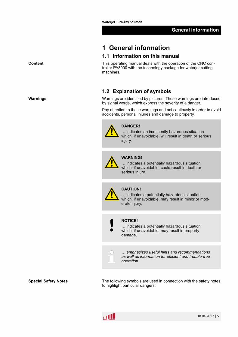
1.2 Explanation of symbolsWarnings are identified by pictures. These warnings are introducedby signal words, which express the severity of a danger.
Pay attention to these warnings and act cautiously in order to avoidaccidents, personal injuries and damage to property.
DANGER!… indicates an imminently hazardous situationwhich, if unavoidable, will result in death or seriousinjury.
WARNING!… indicates a potentially hazardous situationwhich, if unavoidable, could result in death orserious injury.
CAUTION!… indicates a potentially hazardous situationwhich, if unavoidable, may result in minor or mod-erate injury.
NOTICE!… indicates a potentially hazardous situationwhich, if unavoidable, may result in propertydamage.
… emphasizes useful hints and recommendationsas well as information for efficient and trouble-freeoperation.
The following symbols are used in connection with the safety notesto highlight particular dangers:
Content
Warnings
Special Safety Notes
Waterjet Turn-key Solution
General information
18.04.2017 | 5
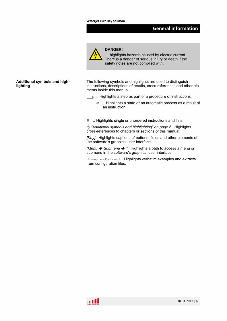
DANGER!… highlights hazards caused by electric current.There is a danger of serious injury or death if thesafety notes are not complied with.
The following symbols and highlights are used to distinguishinstructions, descriptions of results, cross-references and other ele-ments inside this manual.
.. Highlights a step as part of a procedure of instructions.
ð .. Highlights a state or an automatic process as a result ofan instruction.
n .. Highlights single or unordered instructions and lists.
Ä “Additional symbols and highlighting” on page 6.. Highlightscross-references to chapters or sections of this manual.
[Key].. Highlights captions of buttons, fields and other elements ofthe software's graphical user interface.
“Menu è Submenu è ”.. Highlights a path to access a menu orsubmenu in the software's graphical user interface.
Example/Extract.. Highlights verbatim examples and extractsfrom configuration files.
Additional symbols and high-lighting
Waterjet Turn-key Solution
General information
18.04.2017 | 6
1.3 Limitation of liabilityAll information and notes in this operating manual were compiledunder due consideration of valid standards and regulations, thepresent status of technology and our years of knowledge andexperience.
Power Automation can not be held liable for damage resultingfrom:
n disregarding this operating manualn unintended usen employment of untrained personneln unauthorized conversionsn unauthorized modifications to the softwaren technical modificationsn use of unapproved spare partsn use in conjunction with machines not deemed compatible by
Power Automation
In case of customized versions the actual scope of delivery canvary from the explanations and representations in this operatingmanual, because of the utilization of additional options or due tolatest technical changes.
Apart from this, the obligations agreed upon in the delivery con-tract, the general terms and conditions, and the delivery conditionsof Power Automation and the legal regulations valid at the time ofcontract do apply.
We reserve the right to make technical modifications in order toimprove usability.
1.4 CopyrightThis installation manual is protected by copyright law.
Passing this installation manual on to third parties, duplication ofany kind – even in form of excerpts – as well as the use and/or dis-closure of the contents without the written consent of Power Auto-mation is not permitted.
Violations oblige to compensation. The right for further claimsremains reserved.
1.5 Warranty termsThe material warranty terms are provided in Power Automation'sterms and conditions as well as inside the sales documents.
Liability
Copyright
Material Warranty
Waterjet Turn-key Solution
General information
18.04.2017 | 7
1.6 Customer serviceOur Customer Service is always available for technical information.
For information on whom to contact by phone, fax, e-mail or via theinternet, see Power Automation's address on page 2.
Additionally, Power Automation staff is always interested inreceiving new information and experiences resulting from the useof our products, which could be of great value for future improve-ments.
1.7 GlossaryCNC - Computerized Numerical Control
C2C - Contour to contour
HMI - Human Machine Interface
The graphical user interface provided by the PA soft-ware.
HSU - Height sensing unit
Kerf - Radius correction of the tool
MTBP - Machine Tool Builder's Panel
Panel including the basic requirements for a machinetool operator: emergency stop push button, cycle startand stop push buttons, jog plus and minus push but-tons, feed rate and spindle speed override pots and anumber of auxiliary push buttons.
MDI - Manual Data Input
NC-Start - Numerical Control Start Button
NC-Stop - Numerical Control Stop Button
PA - Power Automation
PAMIO - Power Automation Modular Input Output
Extendable Superbus based interface allowingconnection of additional I/O modules.
PC - Personal Computer
PCI - Peripheral Component Interconnect
Personal computer extension for periphery devicesconnected to the motherboard.
RMS - Rotating Measuring Systems (Encoder)
Service
Waterjet Turn-key Solution
General information
18.04.2017 | 8
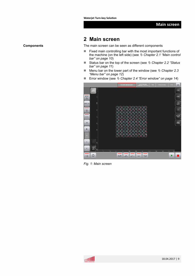
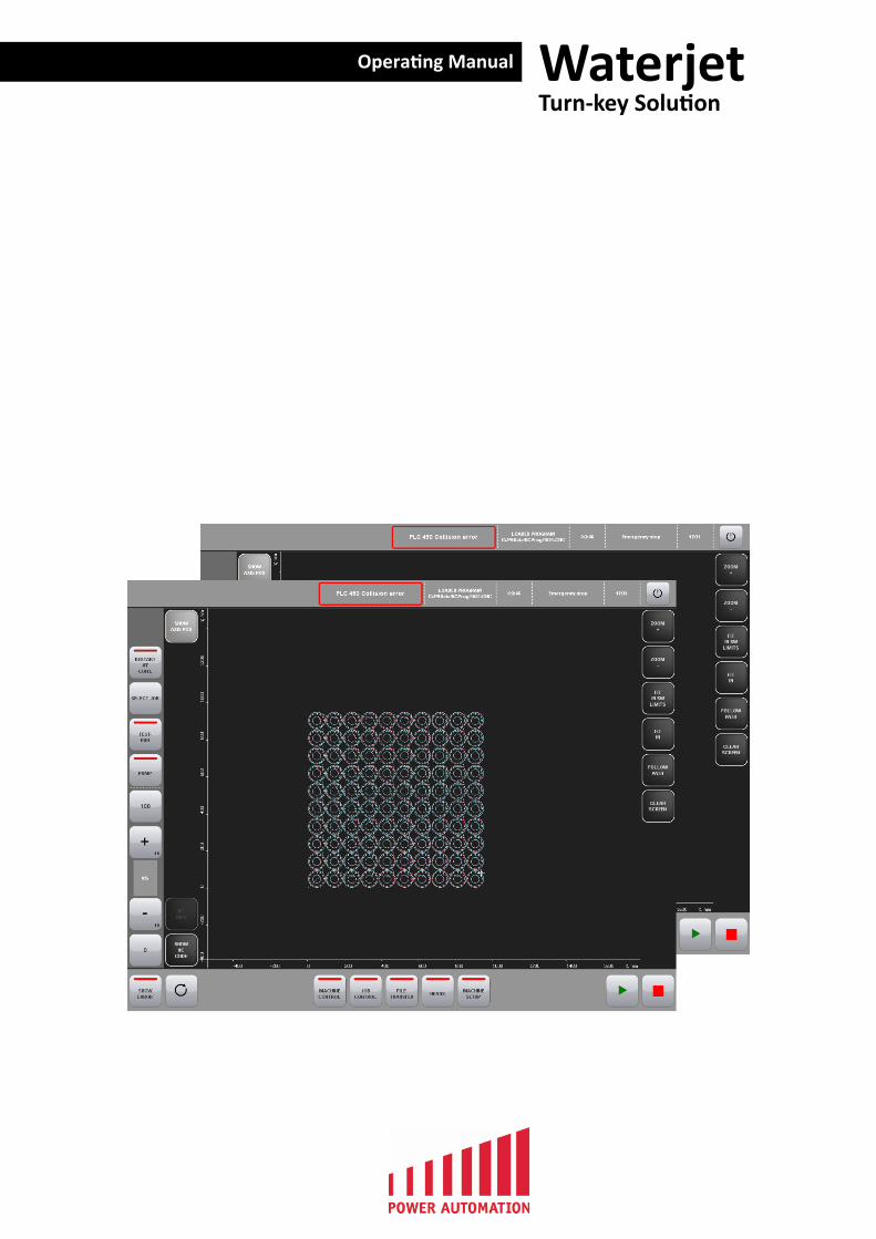
2 Main screenThe main screen can be seen as different components
n Fixed main controlling bar with the most important functions ofthe machine (on the left side) (see Ä Chapter 2.1 “Main controlbar” on page 10)
n Status bar on the top of the screen (see Ä Chapter 2.2 “Statusbar” on page 11)
n Menu bar on the lower part of the window (see Ä Chapter 2.3“Menu bar” on page 12)
n Error window (see Ä Chapter 2.4 “Error window” on page 14)
Fig. 1: Main screen
Components
Waterjet Turn-key Solution
Main screen
18.04.2017 | 9
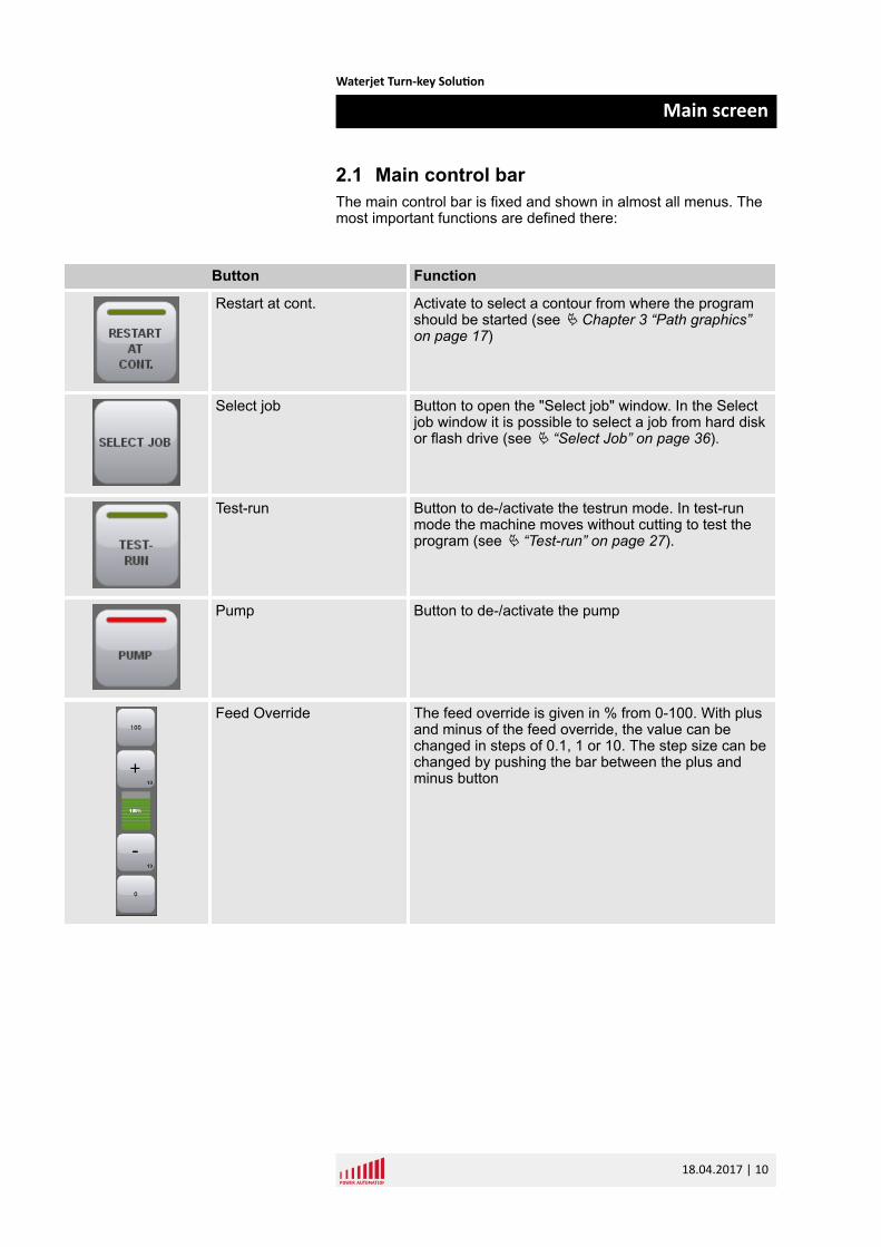
2.1 Main control barThe main control bar is fixed and shown in almost all menus. Themost important functions are defined there:
Button Function
Restart at cont. Activate to select a contour from where the programshould be started (see Ä Chapter 3 “Path graphics”on page 17)
Select job Button to open the "Select job" window. In the Selectjob window it is possible to select a job from hard diskor flash drive (see Ä “Select Job” on page 36).
Test-run Button to de-/activate the testrun mode. In test-runmode the machine moves without cutting to test theprogram (see Ä “Test-run” on page 27).
Pump Button to de-/activate the pump
Feed Override The feed override is given in % from 0-100. With plusand minus of the feed override, the value can bechanged in steps of 0.1, 1 or 10. The step size can bechanged by pushing the bar between the plus andminus button
Waterjet Turn-key Solution
Main screen
18.04.2017 | 10
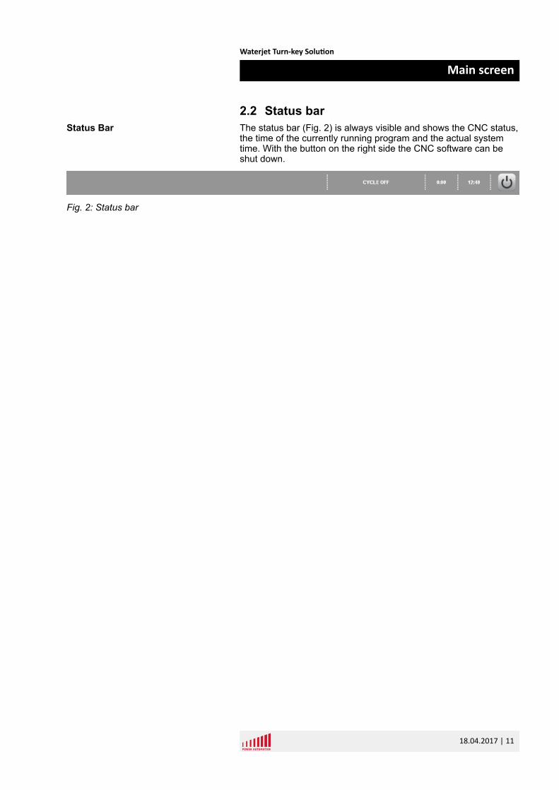
2.2 Status barThe status bar (Fig. 2) is always visible and shows the CNC status,the time of the currently running program and the actual systemtime. With the button on the right side the CNC software can beshut down.
Fig. 2: Status bar
Status Bar
Waterjet Turn-key Solution
Main screen
18.04.2017 | 11
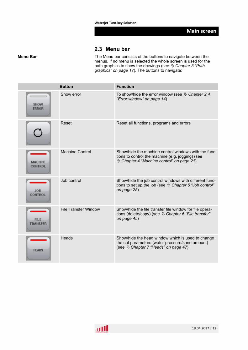
2.3 Menu barThe Menu bar consists of the buttons to navigate between themenus. If no menu is selected the whole screen is used for thepath graphics to show the drawings (see Ä Chapter 3 “Pathgraphics” on page 17). The buttons to navigate:
Button Function
Show error To show/hide the error window (see Ä Chapter 2.4“Error window” on page 14)
Reset Reset all functions, programs and errors
Machine Control Show/hide the machine control windows with the func-tions to control the machine (e.g. jogging) (seeÄ Chapter 4 “Machine control” on page 21)
Job control Show/hide the job control windows with different func-tions to set up the job (see Ä Chapter 5 “Job control”on page 25)
File Transfer Window Show/hide the file transfer file window for file opera-tions (delete/copy) (see Ä Chapter 6 “File transfer”on page 45)
Heads Show/hide the head window which is used to changethe cut parameters (water pressure/sand amount)(see Ä Chapter 7 “Heads” on page 47)
Menu Bar
Waterjet Turn-key Solution
Main screen
18.04.2017 | 12
Button Function
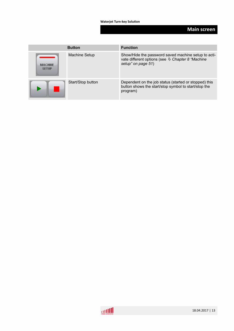
Machine Setup Show/Hide the password saved machine setup to acti-vate different options (see Ä Chapter 8 “Machinesetup” on page 51)
Start/Stop button Dependent on the job status (started or stopped) thisbutton shows the start/stop symbol to start/stop theprogram)
Waterjet Turn-key Solution
Main screen
18.04.2017 | 13
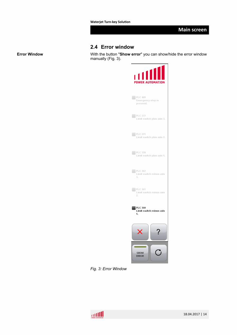
2.4 Error windowWith the button "Show error" you can show/hide the error windowmanually (Fig. 3).
Fig. 3: Error Window
Error Window
Waterjet Turn-key Solution
Main screen
18.04.2017 | 14
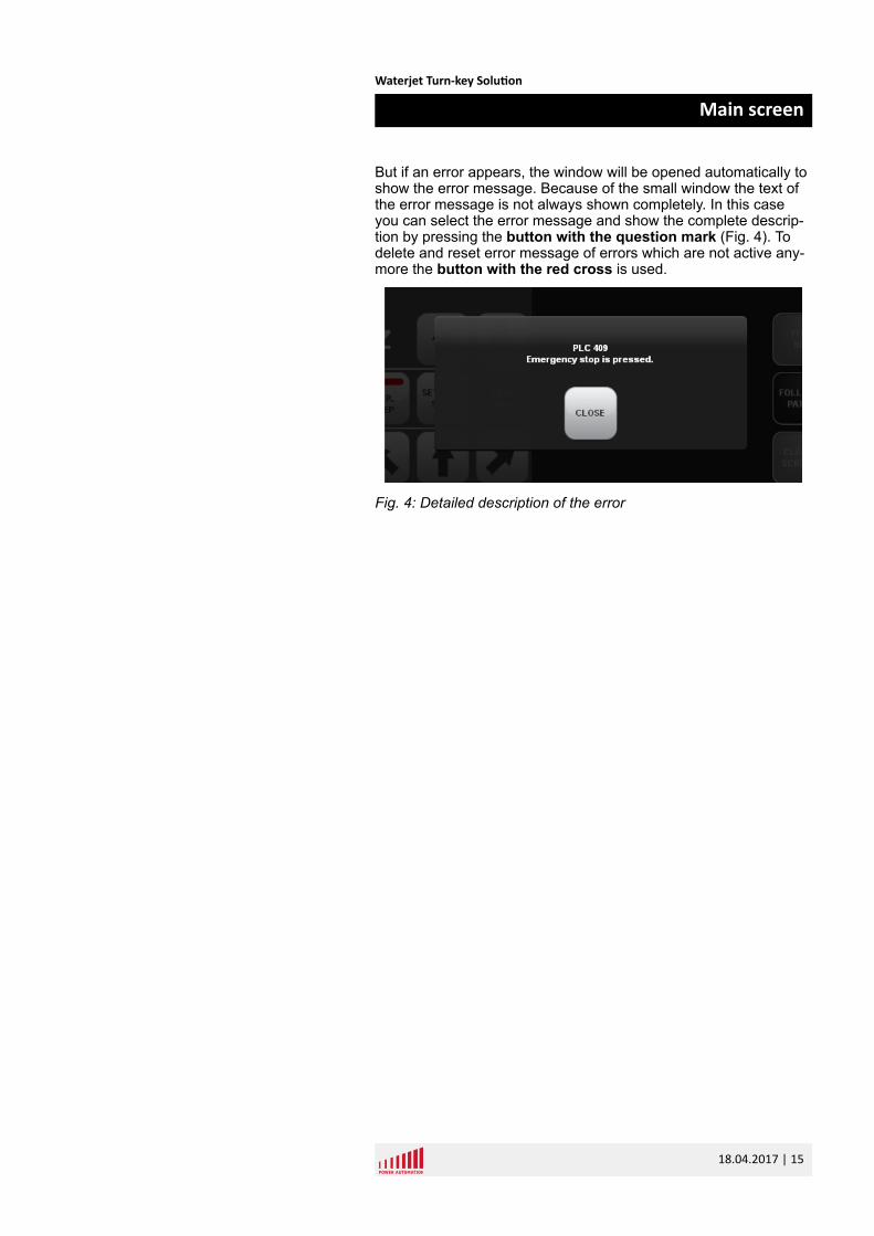
But if an error appears, the window will be opened automatically toshow the error message. Because of the small window the text ofthe error message is not always shown completely. In this caseyou can select the error message and show the complete descrip-tion by pressing the button with the question mark (Fig. 4). Todelete and reset error message of errors which are not active any-more the button with the red cross is used.
Fig. 4: Detailed description of the error
Waterjet Turn-key Solution
Main screen
18.04.2017 | 15

Waterjet Turn-key Solution
Main screen
18.04.2017 | 16
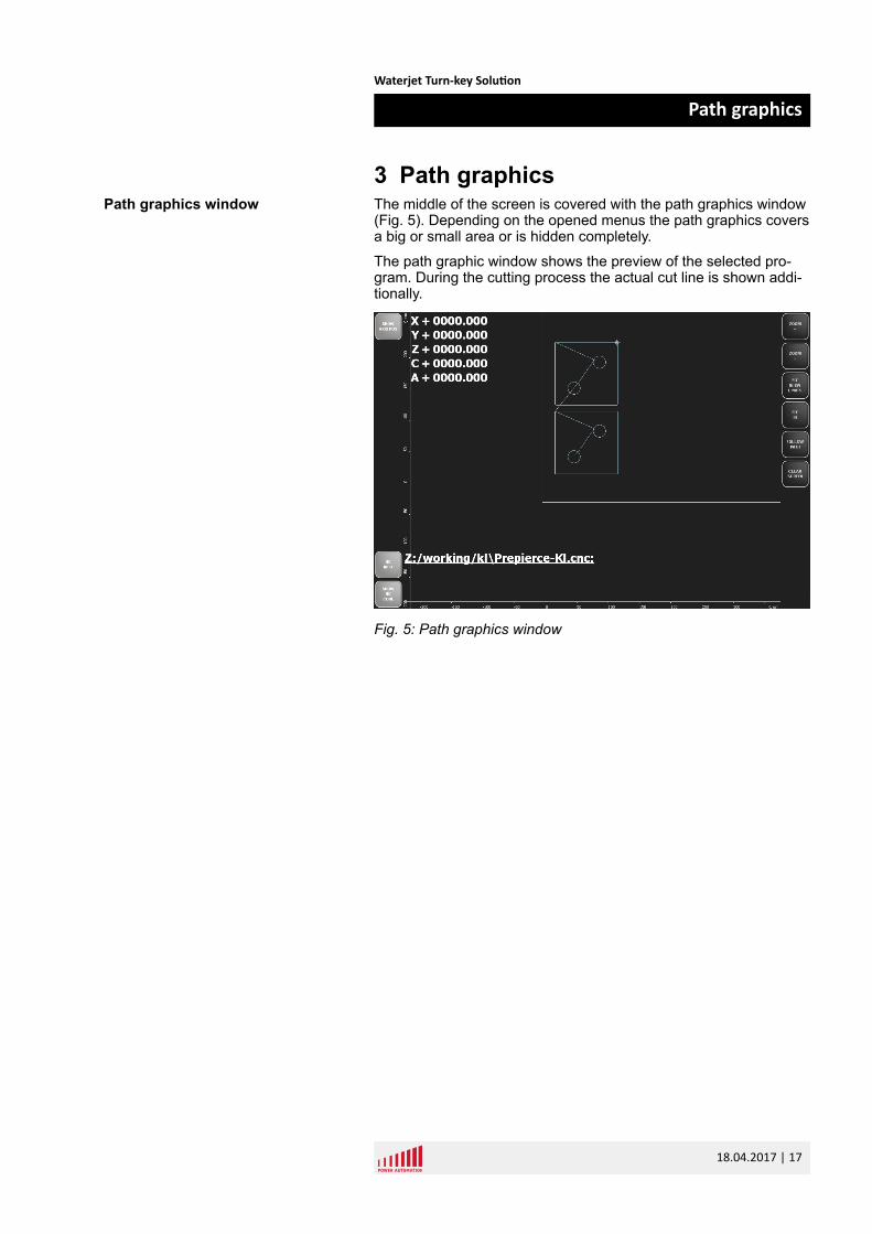
3 Path graphicsThe middle of the screen is covered with the path graphics window(Fig. 5). Depending on the opened menus the path graphics coversa big or small area or is hidden completely.
The path graphic window shows the preview of the selected pro-gram. During the cutting process the actual cut line is shown addi-tionally.
Fig. 5: Path graphics window
Path graphics window
Waterjet Turn-key Solution
Path graphics
18.04.2017 | 17
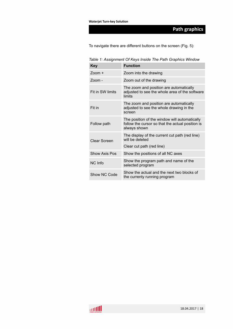
To navigate there are different buttons on the screen (Fig. 5):
Table 1: Assignment Of Keys Inside The Path Graphics WindowKey Function
Zoom + Zoom into the drawing
Zoom - Zoom out of the drawing
Fit in SW limitsThe zoom and position are automaticallyadjusted to see the whole area of the softwarelimits
Fit inThe zoom and position are automaticallyadjusted to see the whole drawing in thescreen
Follow pathThe position of the window will automaticallyfollow the cursor so that the actual position isalways shown
Clear ScreenThe display of the current cut path (red line)will be deleted
Clear cut path (red line)
Show Axis Pos Show the positions of all NC axes
NC Info Show the program path and name of theselected program
Show NC Code Show the actual and the next two blocks ofthe currenty running program
Waterjet Turn-key Solution
Path graphics
18.04.2017 | 18
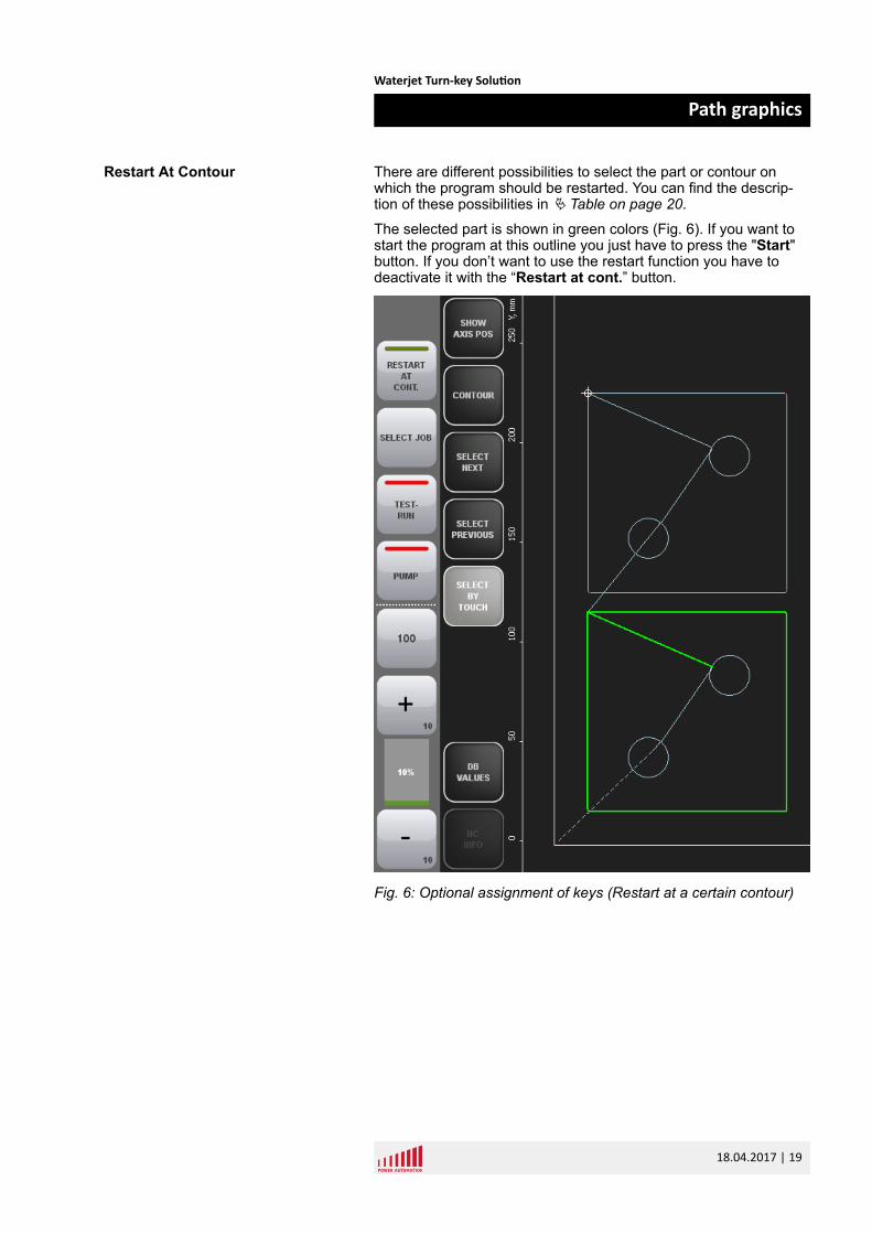
There are different possibilities to select the part or contour onwhich the program should be restarted. You can find the descrip-tion of these possibilities in Ä Table on page 20.
The selected part is shown in green colors (Fig. 6). If you want tostart the program at this outline you just have to press the "Start"button. If you don’t want to use the restart function you have todeactivate it with the “Restart at cont.” button.
Fig. 6: Optional assignment of keys (Restart at a certain contour)
Restart At Contour
Waterjet Turn-key Solution
Path graphics
18.04.2017 | 19
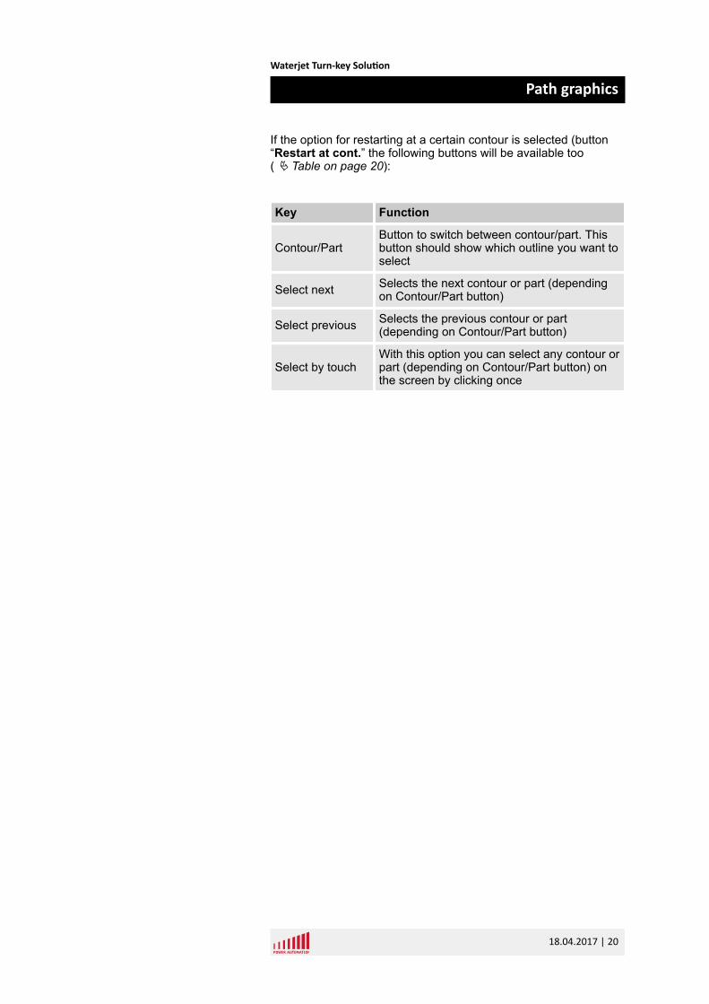
If the option for restarting at a certain contour is selected (button“Restart at cont.” the following buttons will be available too( Ä Table on page 20):
Key Function
Contour/PartButton to switch between contour/part. Thisbutton should show which outline you want toselect
Select next Selects the next contour or part (dependingon Contour/Part button)
Select previous Selects the previous contour or part(depending on Contour/Part button)
Select by touchWith this option you can select any contour orpart (depending on Contour/Part button) onthe screen by clicking once
Waterjet Turn-key Solution
Path graphics
18.04.2017 | 20
4 Machine controlThe machine control window is used for controlling the machine.There are defined different move options, jog button, feed overridesettings. The machine control is divided into two windows whichare positioned on the left and right side of the screen.
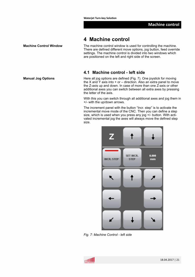
4.1 Machine control - left sideHere all jog options are defined (Fig. 7). One joystick for movingthe X and Y axis into + or – direction. Also an extra panel to movethe Z-axis up and down. In case of more than one Z-axis or otheradditional axes you can switch between all extra axes by pressingthe letter of the axis.
With this you can switch through all additional axes and jog them in+/- with the up/down arrows.
The increment panel with the button “Incr. step” is to activate theincremental move mode of the CNC. Then you can define a stepsize, which is used when you press any jog +/- button. With acti-vated incremental jog the axes will always move the defined stepsize.
Fig. 7: Machine Control - left side
Machine Control Window
Manual Jog Options
Waterjet Turn-key Solution
Machine control
18.04.2017 | 21
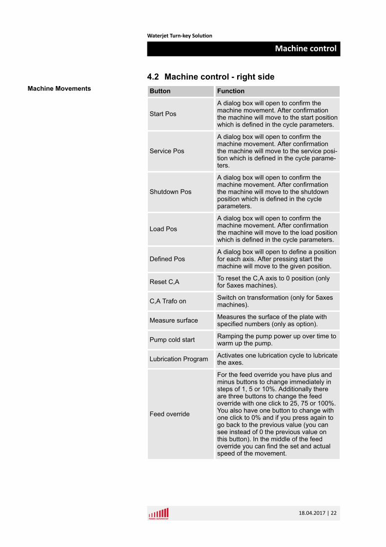
4.2 Machine control - right sideButton Function
Start PosA dialog box will open to confirm themachine movement. After confirmationthe machine will move to the start positionwhich is defined in the cycle parameters.
Service Pos
A dialog box will open to confirm themachine movement. After confirmationthe machine will move to the service posi-tion which is defined in the cycle parame-ters.
Shutdown Pos
A dialog box will open to confirm themachine movement. After confirmationthe machine will move to the shutdownposition which is defined in the cycleparameters.
Load PosA dialog box will open to confirm themachine movement. After confirmationthe machine will move to the load positionwhich is defined in the cycle parameters.
Defined PosA dialog box will open to define a positionfor each axis. After pressing start themachine will move to the given position.
Reset C,A To reset the C,A axis to 0 position (onlyfor 5axes machines).
C,A Trafo on Switch on transformation (only for 5axesmachines).
Measure surface Measures the surface of the plate withspecified numbers (only as option).
Pump cold start Ramping the pump power up over time towarm up the pump.
Lubrication Program Activates one lubrication cycle to lubricatethe axes.
Feed override
For the feed override you have plus andminus buttons to change immediately insteps of 1, 5 or 10%. Additionally thereare three buttons to change the feedoverride with one click to 25, 75 or 100%.You also have one button to change withone click to 0% and if you press again togo back to the previous value (you cansee instead of 0 the previous value onthis button). In the middle of the feedoverride you can find the set and actualspeed of the movement.
Machine Movements
Waterjet Turn-key Solution
Machine control
18.04.2017 | 22
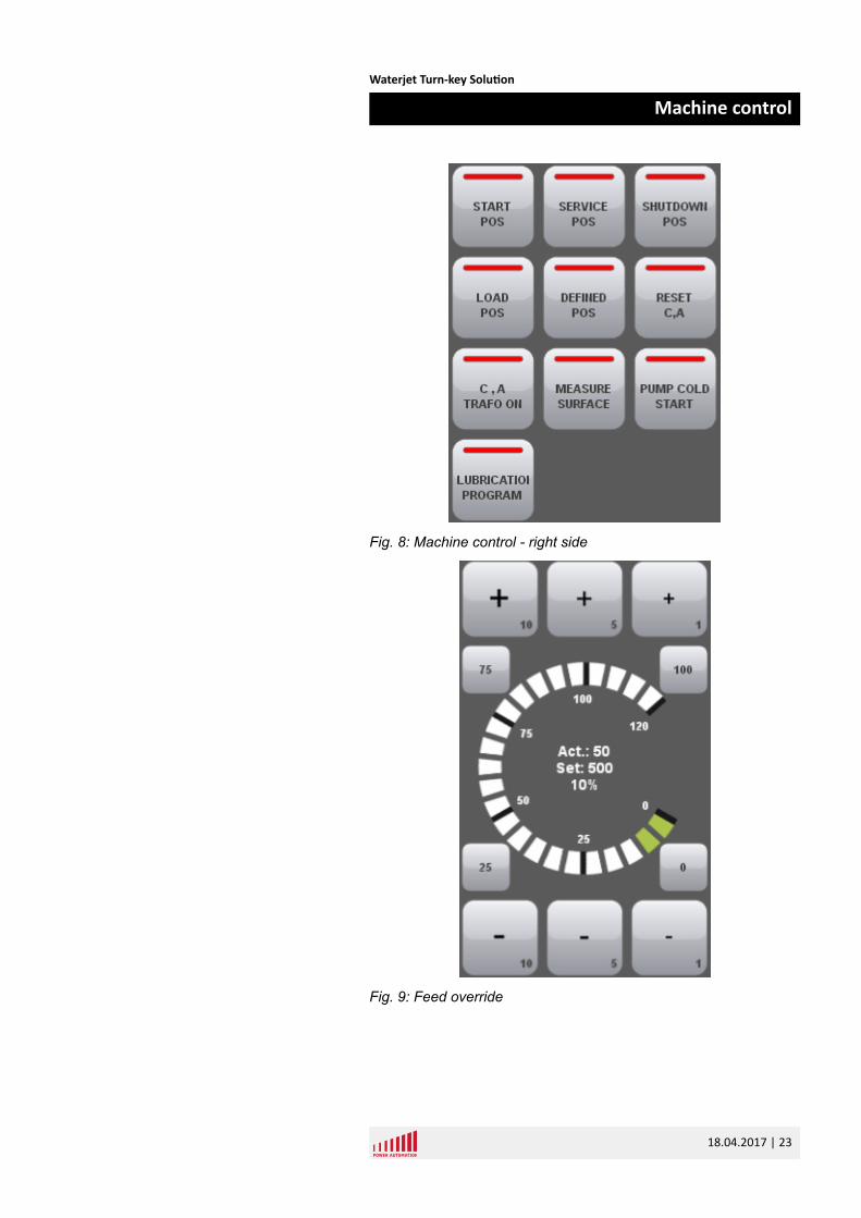
Fig. 8: Machine control - right side
Fig. 9: Feed override
Waterjet Turn-key Solution
Machine control
18.04.2017 | 23

Waterjet Turn-key Solution
Machine control
18.04.2017 | 24
5 Job controlThe job control window has two different views. The view and func-tionality is dependent on the actual CNC status. If the program isactive you can see functions which are made to affect the machineduring the cutting process. If no program is active all functions aredisplayed which are used for setting up parameters before the startof a program.
5.1 Job control cycle off – left side
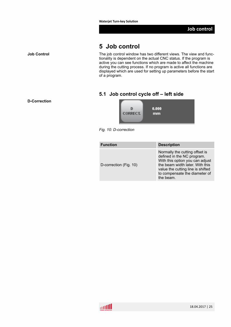
Fig. 10: D-correction
Function Description
D-correction (Fig. 10)
Normally the cutting offset isdefined in the NC program.With this option you can adjustthe beam width later. With thisvalue the cutting line is shiftedto compensate the diameter ofthe beam.
Job Control
D-Correction
Waterjet Turn-key Solution
Job control
18.04.2017 | 25
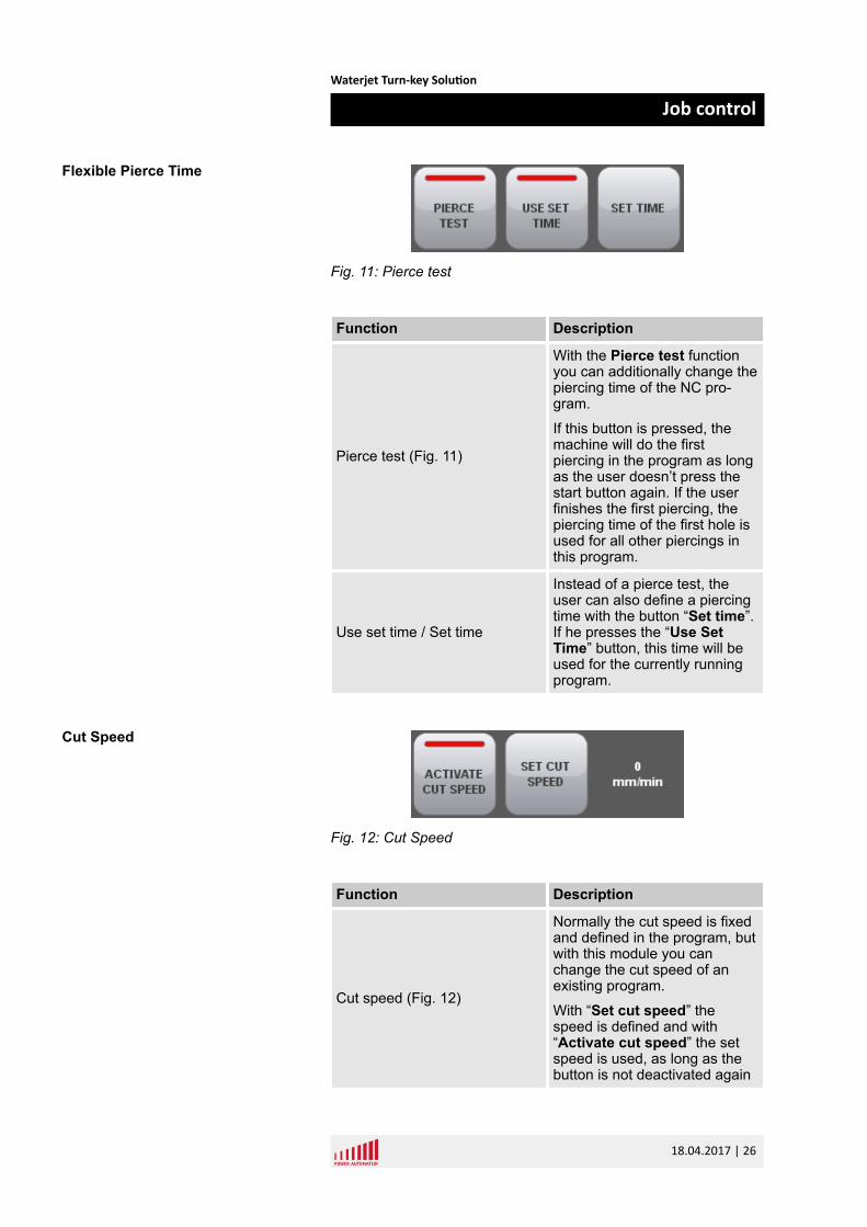
Fig. 11: Pierce test
Function Description
Pierce test (Fig. 11)
With the Pierce test functionyou can additionally change thepiercing time of the NC pro-gram.
If this button is pressed, themachine will do the firstpiercing in the program as longas the user doesn’t press thestart button again. If the userfinishes the first piercing, thepiercing time of the first hole isused for all other piercings inthis program.
Use set time / Set time
Instead of a pierce test, theuser can also define a piercingtime with the button “Set time”.If he presses the “Use SetTime” button, this time will beused for the currently runningprogram.
Fig. 12: Cut Speed
Function Description
Cut speed (Fig. 12)
Normally the cut speed is fixedand defined in the program, butwith this module you canchange the cut speed of anexisting program.
With “Set cut speed” thespeed is defined and with“Activate cut speed” the setspeed is used, as long as thebutton is not deactivated again
Flexible Pierce Time
Cut Speed
Waterjet Turn-key Solution
Job control
18.04.2017 | 26
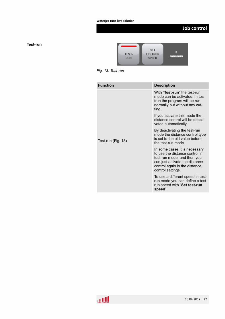
Fig. 13: Test-run
Function Description
Test-run (Fig. 13)
With “Test-run” the test-runmode can be activated. In tes-trun the program will be runnormally but without any cut-ting.
If you activate this mode thedistance control will be deacti-vated automatically.
By deactivating the test-runmode the distance control typeis set to the old value beforethe test-run mode.
In some cases it is necessaryto use the distance control intest-run mode, and then youcan just activate the distancecontrol again in the distancecontrol settings.
To use a different speed in test-run mode you can define a test-run speed with “Set test-runspeed”.
Test-run
Waterjet Turn-key Solution
Job control
18.04.2017 | 27
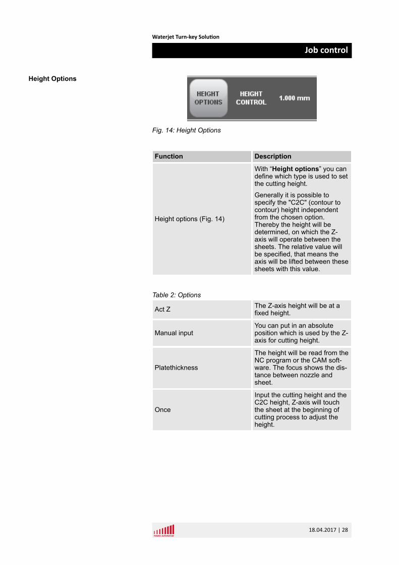
Fig. 14: Height Options
Function Description
Height options (Fig. 14)
With “Height options” you candefine which type is used to setthe cutting height.
Generally it is possible tospecify the "C2C" (contour tocontour) height independentfrom the chosen option.Thereby the height will bedetermined, on which the Z-axis will operate between thesheets. The relative value willbe specified, that means theaxis will be lifted between thesesheets with this value.
Table 2: Options
Act Z The Z-axis height will be at afixed height.
Manual inputYou can put in an absoluteposition which is used by the Z-axis for cutting height.
Platethickness
The height will be read from theNC program or the CAM soft-ware. The focus shows the dis-tance between nozzle andsheet.
Once
Input the cutting height and theC2C height, Z-axis will touchthe sheet at the beginning ofcutting process to adjust theheight.
Height Options
Waterjet Turn-key Solution
Job control
18.04.2017 | 28
At pierceInput the cutting height, the Z-axis will touch at each piercingto get the height.
Plate comp
n Input the cutting height, thesheet width and length andthe number of points in Xand Y direction.
n The machine will measurethe distance on the wholesheet on the X and Y pointsand save them.
n After finishing measure-ment the machine will startcutting. Then the height willbe compensated automati-cally.
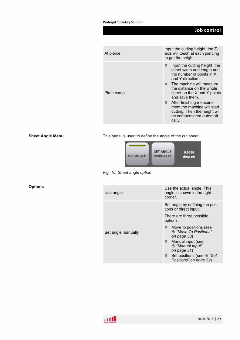
This panel is used to define the angle of the cut sheet.
Fig. 15: Sheet angle option
Use angleUse the actual angle. Thisangle is shown in the rightcorner.
Set angle manually
Set angle by defining the posi-tions or direct input.
There are three possibleoptions:
n Move to positions (seeÄ “Move To Positions”on page 30)
n Manual input (seeÄ “Manual Input”on page 31)
n Set positions (see Ä “SetPositions” on page 32)
Sheet Angle Menu
Options
Waterjet Turn-key Solution
Job control
18.04.2017 | 29
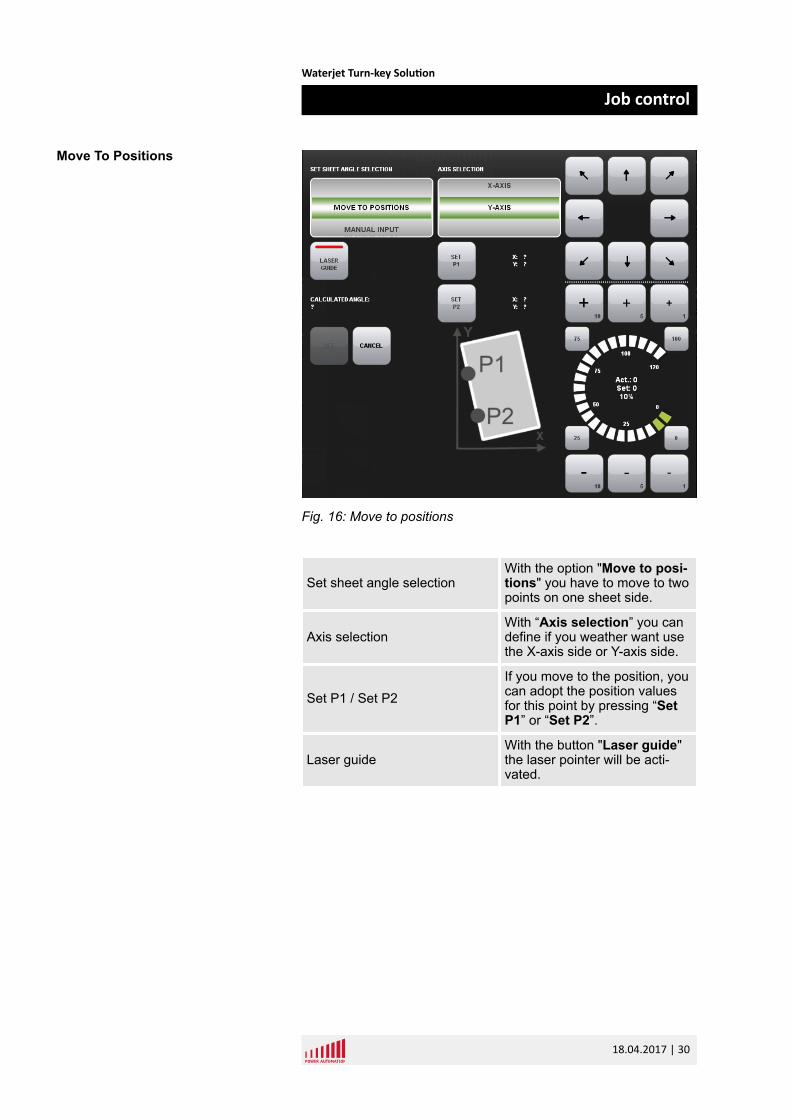
Fig. 16: Move to positions
Set sheet angle selectionWith the option "Move to posi-tions" you have to move to twopoints on one sheet side.
Axis selectionWith “Axis selection” you candefine if you weather want usethe X-axis side or Y-axis side.
Set P1 / Set P2If you move to the position, youcan adopt the position valuesfor this point by pressing “SetP1” or “Set P2”.
Laser guideWith the button "Laser guide"the laser pointer will be acti-vated.
Move To Positions
Waterjet Turn-key Solution
Job control
18.04.2017 | 30
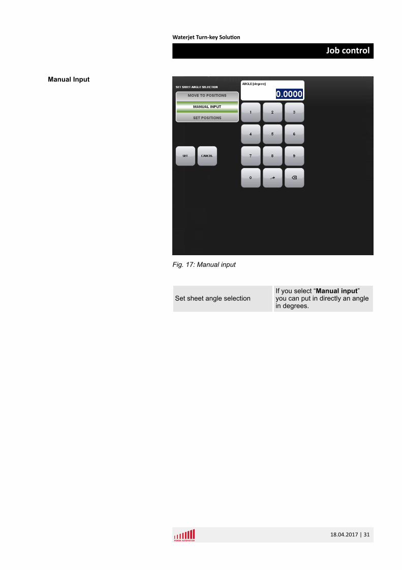
Fig. 17: Manual input
Set sheet angle selectionIf you select “Manual input”you can put in directly an anglein degrees.
Manual Input
Waterjet Turn-key Solution
Job control
18.04.2017 | 31
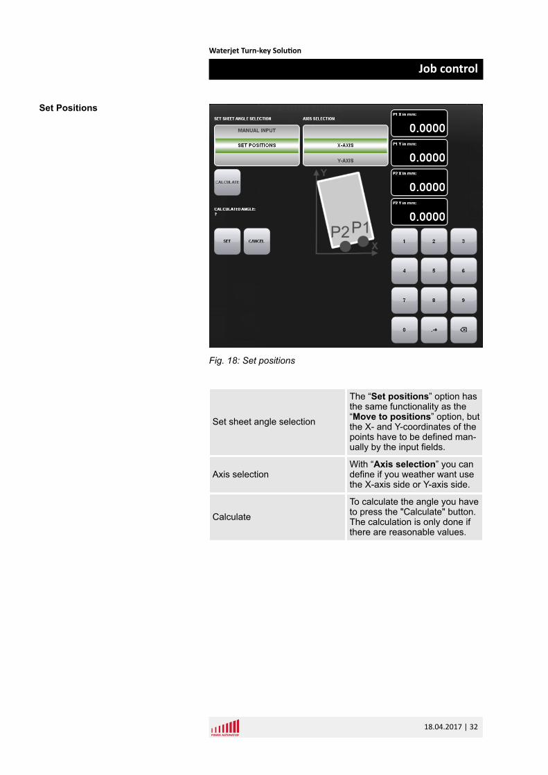
Fig. 18: Set positions
Set sheet angle selection
The “Set positions” option hasthe same functionality as the“Move to positions” option, butthe X- and Y-coordinates of thepoints have to be defined man-ually by the input fields.
Axis selectionWith “Axis selection” you candefine if you weather want usethe X-axis side or Y-axis side.
CalculateTo calculate the angle you haveto press the "Calculate" button.The calculation is only done ifthere are reasonable values.
Set Positions
Waterjet Turn-key Solution
Job control
18.04.2017 | 32
5.2 Job control cycle off – right side
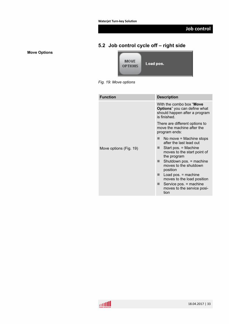
Fig. 19: Move options
Function Description
Move options (Fig. 19)
With the combo box “MoveOptions” you can define whatshould happen after a programis finished.
There are different options tomove the machine after theprogram ends:
n No move = Machine stopsafter the last lead out
n Start pos. = Machinemoves to the start point ofthe program
n Shutdown pos. = machinemoves to the shutdownposition
n Load pos. = machinemoves to the load position
n Service pos. = machinemoves to the service posi-tion
Move Options
Waterjet Turn-key Solution
Job control
18.04.2017 | 33
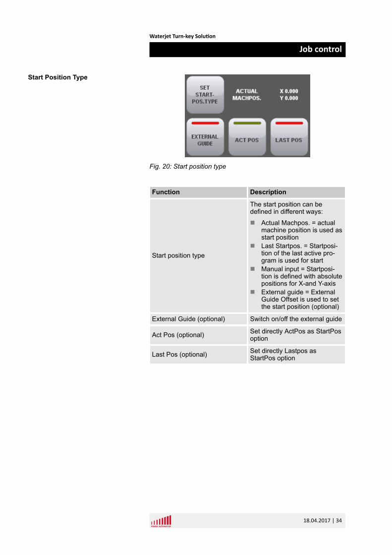
Fig. 20: Start position type
Function Description
Start position type
The start position can bedefined in different ways:
n Actual Machpos. = actualmachine position is used asstart position
n Last Startpos. = Startposi-tion of the last active pro-gram is used for start
n Manual input = Startposi-tion is defined with absolutepositions for X-and Y-axis
n External guide = ExternalGuide Offset is used to setthe start position (optional)
External Guide (optional) Switch on/off the external guide
Act Pos (optional) Set directly ActPos as StartPosoption
Last Pos (optional) Set directly Lastpos asStartPos option
Start Position Type
Waterjet Turn-key Solution
Job control
18.04.2017 | 34
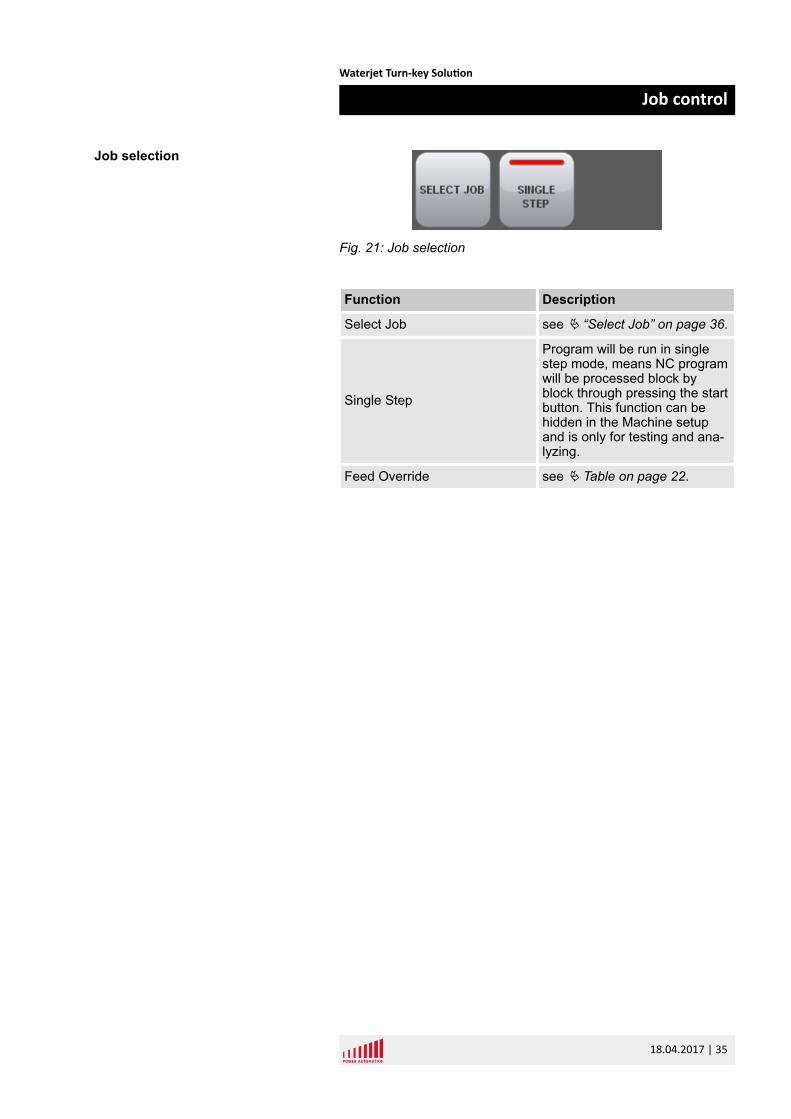
Fig. 21: Job selection
Function Description
Select Job see Ä “Select Job” on page 36.
Single Step
Program will be run in singlestep mode, means NC programwill be processed block byblock through pressing the startbutton. This function can behidden in the Machine setupand is only for testing and ana-lyzing.
Feed Override see Ä Table on page 22.
Job selection
Waterjet Turn-key Solution
Job control
18.04.2017 | 35
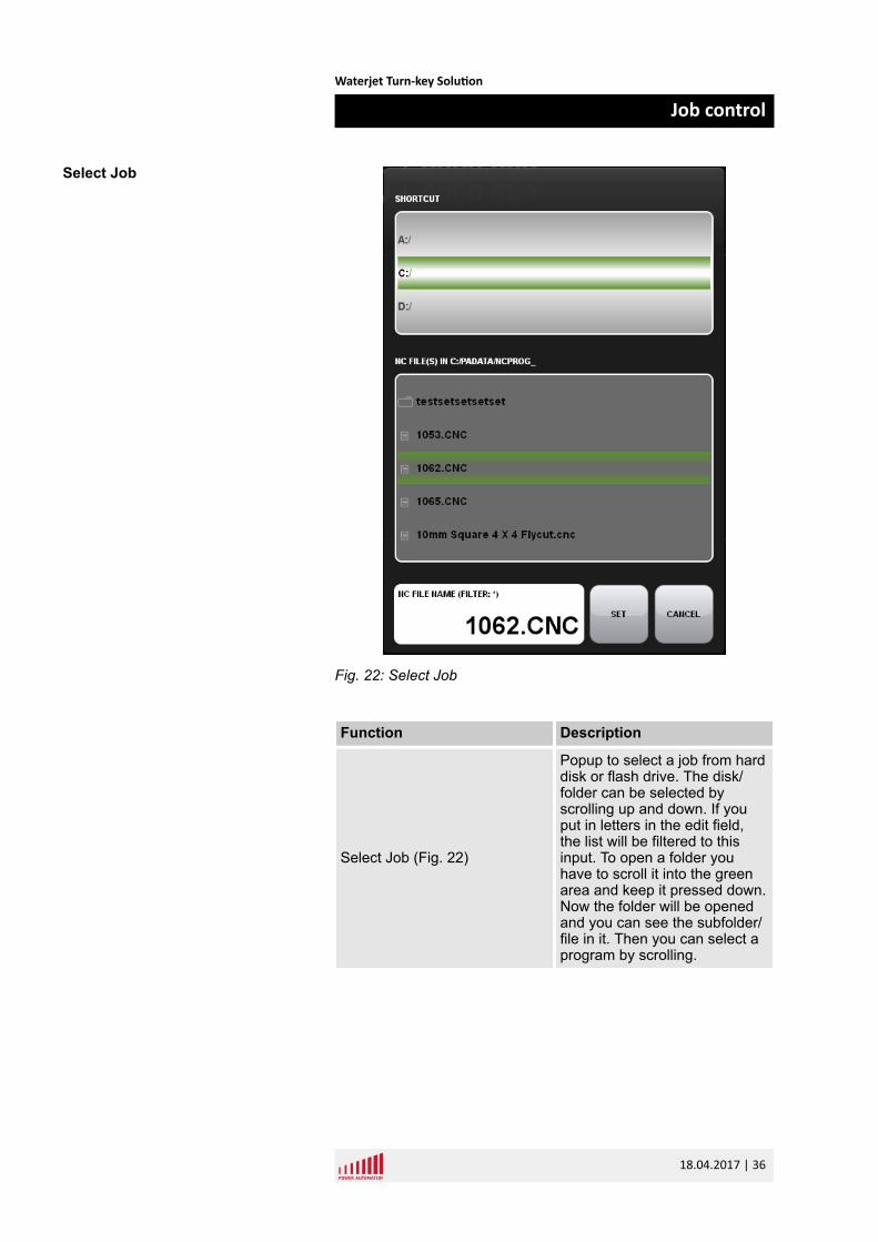
Fig. 22: Select Job
Function Description
Select Job (Fig. 22)
Popup to select a job from harddisk or flash drive. The disk/folder can be selected byscrolling up and down. If youput in letters in the edit field,the list will be filtered to thisinput. To open a folder youhave to scroll it into the greenarea and keep it pressed down.Now the folder will be openedand you can see the subfolder/file in it. Then you can select aprogram by scrolling.
Select Job
Waterjet Turn-key Solution
Job control
18.04.2017 | 36
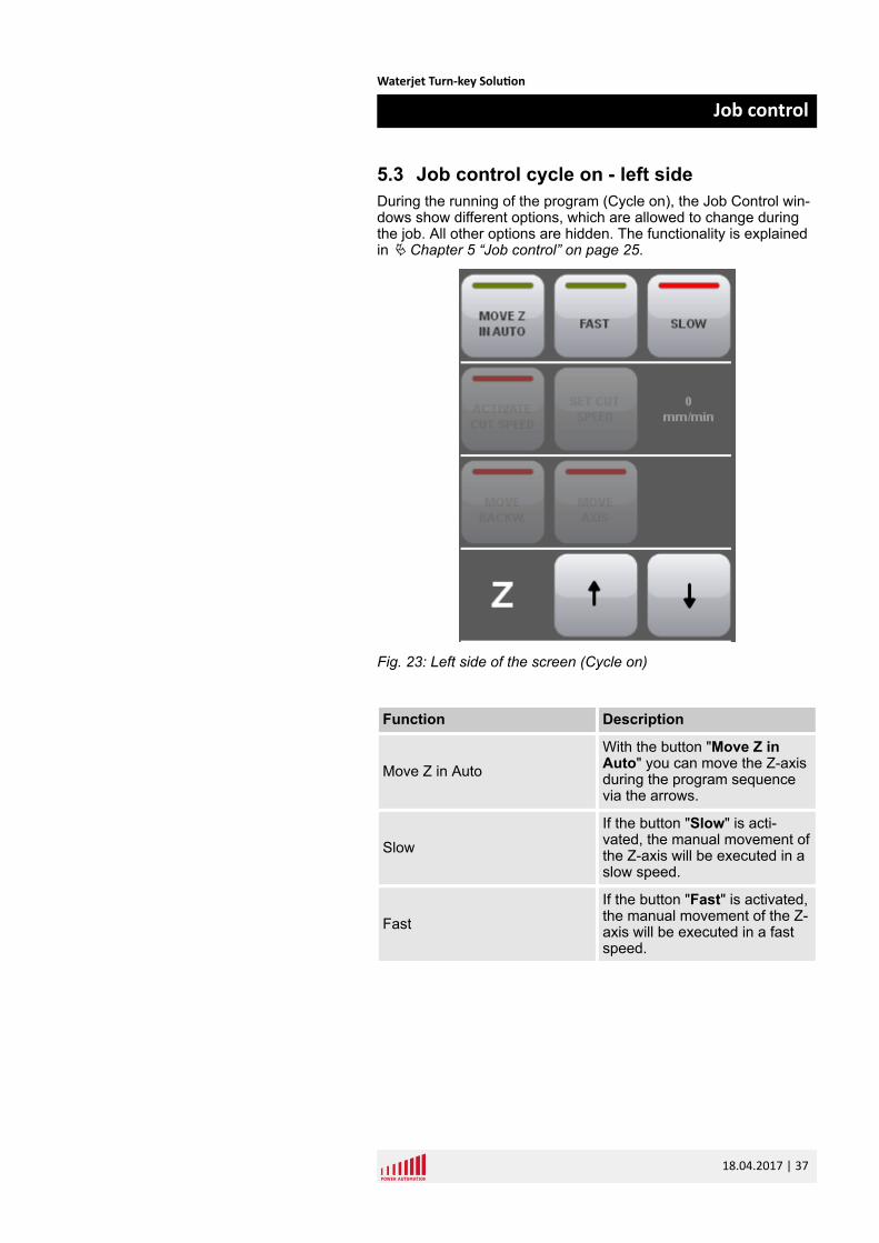
5.3 Job control cycle on - left sideDuring the running of the program (Cycle on), the Job Control win-dows show different options, which are allowed to change duringthe job. All other options are hidden. The functionality is explainedin Ä Chapter 5 “Job control” on page 25.
Fig. 23: Left side of the screen (Cycle on)
Function Description
Move Z in AutoWith the button "Move Z inAuto" you can move the Z-axisduring the program sequencevia the arrows.
SlowIf the button "Slow" is acti-vated, the manual movement ofthe Z-axis will be executed in aslow speed.
FastIf the button "Fast" is activated,the manual movement of the Z-axis will be executed in a fastspeed.
Waterjet Turn-key Solution
Job control
18.04.2017 | 37
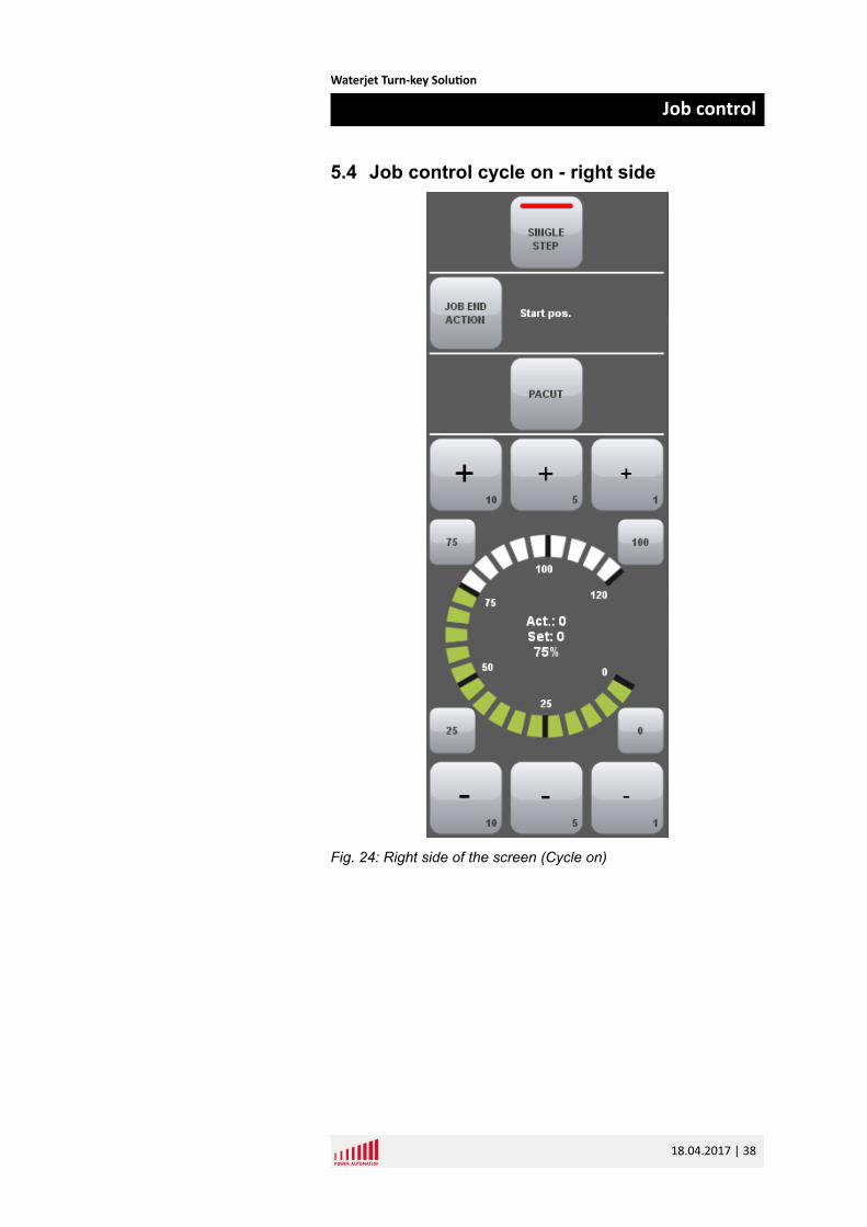
5.4 Job control cycle on - right side
Fig. 24: Right side of the screen (Cycle on)
Waterjet Turn-key Solution
Job control
18.04.2017 | 38
Function Description
Single Step see Ä “Job selection” on page 35
Job End Action
In this option you can define what shouldhappen after finishing the job:
n No movementn Move to start positionn Move to service positionn Move to shutdown positionn Move to load position
See Ä “Move Options” on page 33.
PACUTThis function is only available if you are usingthe PaCut on the control to generate the NCprograms. With this button you can switch tothe PaCut program or start it.
Feed Override see Ä Table on page 22
Waterjet Turn-key Solution
Job control
18.04.2017 | 39
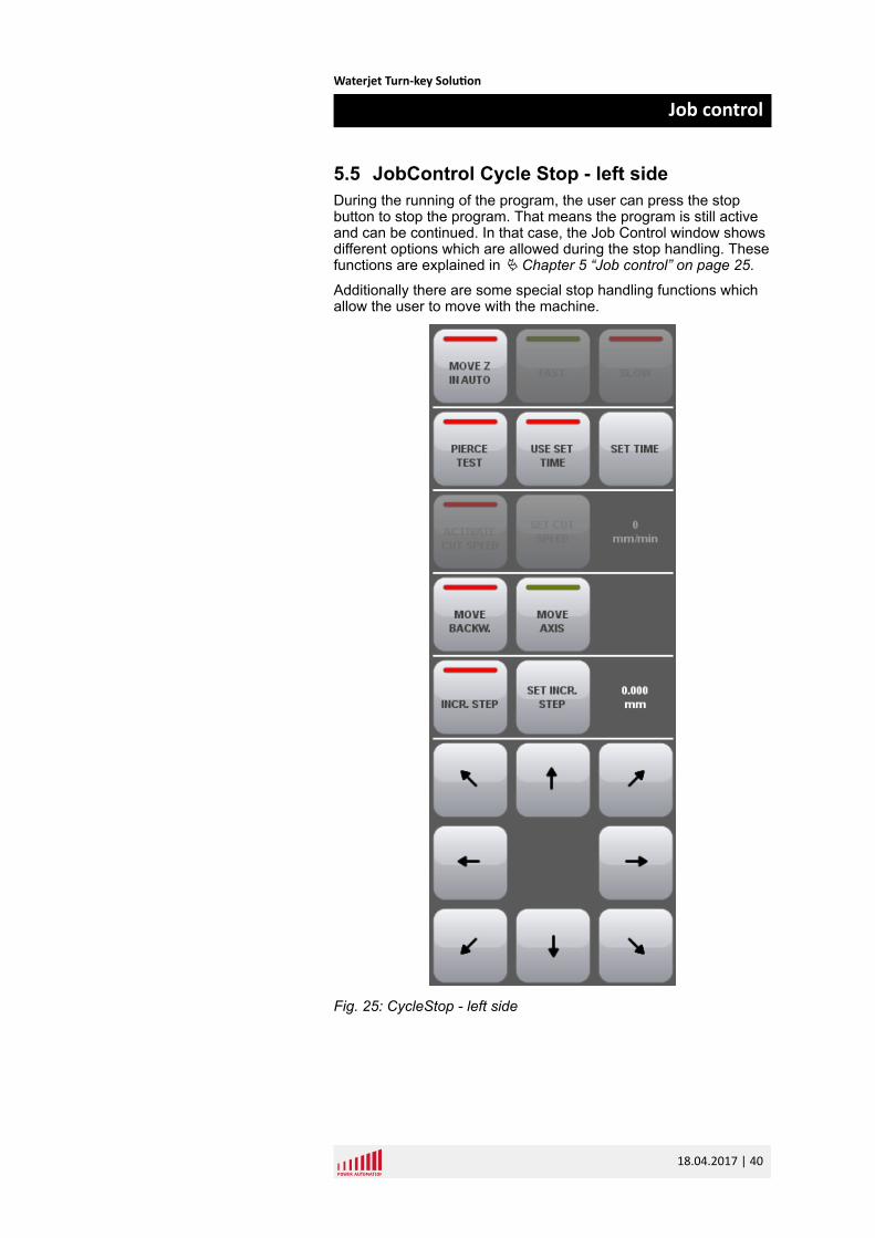
5.5 JobControl Cycle Stop - left sideDuring the running of the program, the user can press the stopbutton to stop the program. That means the program is still activeand can be continued. In that case, the Job Control window showsdifferent options which are allowed during the stop handling. Thesefunctions are explained in Ä Chapter 5 “Job control” on page 25.
Additionally there are some special stop handling functions whichallow the user to move with the machine.
Fig. 25: CycleStop - left side
Waterjet Turn-key Solution
Job control
18.04.2017 | 40
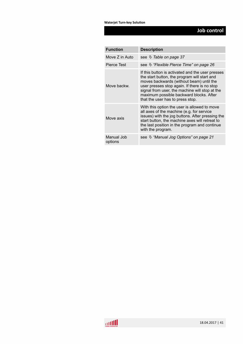
Function Description
Move Z in Auto see Ä Table on page 37
Pierce Test see Ä “Flexible Pierce Time” on page 26
Move backw.
If this button is activated and the user pressesthe start button, the program will start andmoves backwards (without beam) until theuser presses stop again. If there is no stopsignal from user, the machine will stop at themaximum possible backward blocks. Afterthat the user has to press stop.
Move axis
With this option the user is allowed to moveall axes of the machine (e.g. for serviceissues) with the jog buttons. After pressing thestart button, the machine axes will retreat tothe last position in the program and continuewith the program.
Manual Joboptions
see Ä “Manual Jog Options” on page 21
Waterjet Turn-key Solution
Job control
18.04.2017 | 41
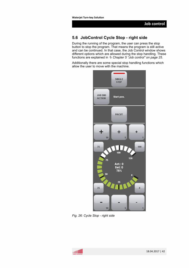
5.6 JobControl Cycle Stop - right sideDuring the running of the program, the user can press the stopbutton to stop the program. That means the program is still activeand can be continued. In that case, the Job Control window showsdifferent options which are allowed during the stop handling. Thesefunctions are explained in Ä Chapter 5 “Job control” on page 25.
Additionally there are some special stop handling functions whichallow the user to move with the machine.
Fig. 26: Cycle Stop - right side
Waterjet Turn-key Solution
Job control
18.04.2017 | 42
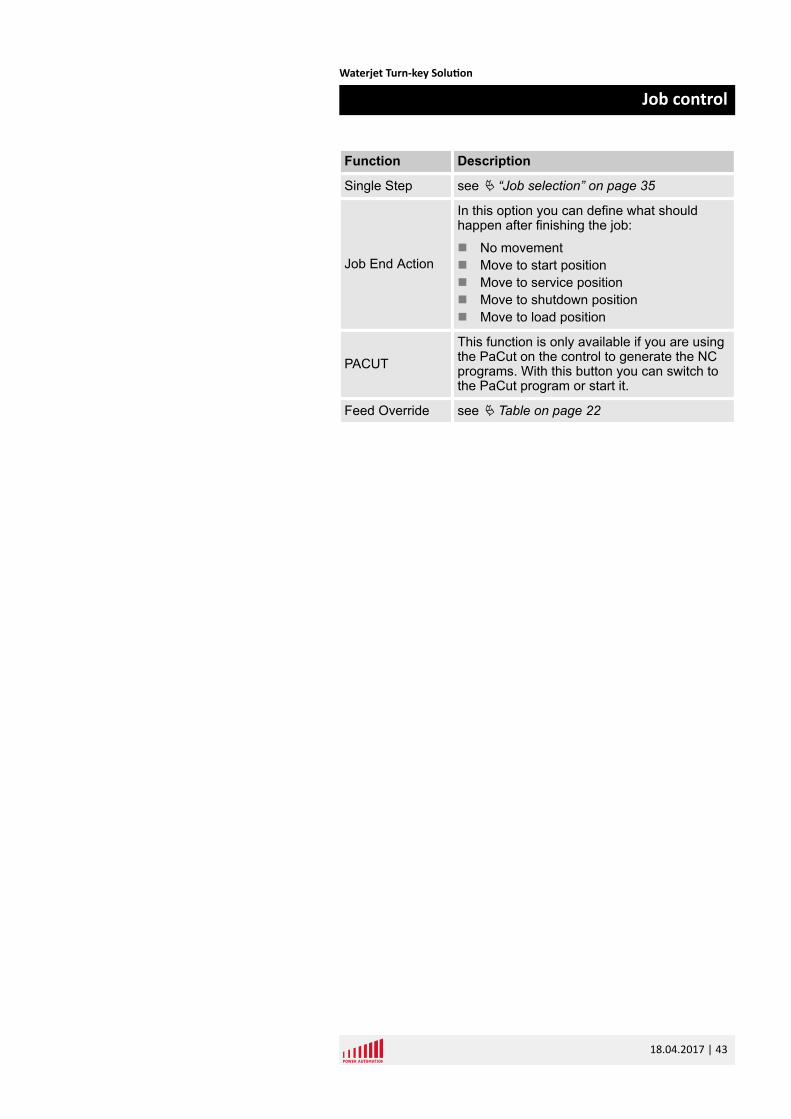
Function Description
Single Step see Ä “Job selection” on page 35
Job End Action
In this option you can define what shouldhappen after finishing the job:
n No movementn Move to start positionn Move to service positionn Move to shutdown positionn Move to load position
PACUTThis function is only available if you are usingthe PaCut on the control to generate the NCprograms. With this button you can switch tothe PaCut program or start it.
Feed Override see Ä Table on page 22
Waterjet Turn-key Solution
Job control
18.04.2017 | 43

Waterjet Turn-key Solution
Job control
18.04.2017 | 44
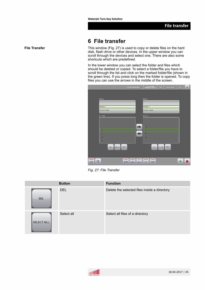
6 File transferThis window (Fig. 27) is used to copy or delete files on the harddisk, flash drive or other devices. In the upper window you canscroll through the devices and select one. There are also someshortcuts which are predefined.
In the lower window you can select the folder and files whichshould be deleted or copied. To select a folder/file you have toscroll through the list and click on the marked folder/file (shown inthe green line). If you press long then the folder is opened. To copyfiles you can use the arrows in the middle of the screen.
Fig. 27: File Transfer
Button Function
DEL Delete the selected files inside a directory
Select all Select all files of a directory
File Transfer
Waterjet Turn-key Solution
File transfer
18.04.2017 | 45
Button Function
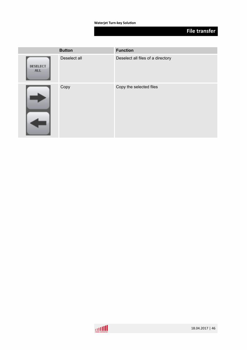
Deselect all Deselect all files of a directory
Copy Copy the selected files
Waterjet Turn-key Solution
File transfer
18.04.2017 | 46
7 HeadsThe Heads window (Fig. 28) shows all heads of the machine.There are panels for each head to set the specific settings. Withthe “Water” and “Sand” buttons you can activate/deactivate thewater valve or the sand feeding.
This can be done all the time (with activated or deactivated pro-gram). With program start the water and sand will be activatedautomatically depending on the program but you can interact atany time.
If you want to change the water pressure or the sand amount youhave activate the button “Change cut par”. Then you are allowedto change the water pressure with the plus and minus button insteps of "100" or "500".
To change the step size you have to click on the bar on the rightside.
Also the sand amount can be changed in the same way. Here thesteps are "10" and "100".
If you want to go on with the values from the program you have todeactivate the “Change cut par” button. Then the pressure will bereset with the next part/contour.
Heads Window
Waterjet Turn-key Solution
Heads
18.04.2017 | 47

Fig. 28: Heads Window
Button Function
Use Set time
see Ä “Flexible Pierce Time” on page 26
Set time
see Ä “Flexible Pierce Time” on page 26
Set Cut speed
see Ä “Cut Speed” on page 26
Waterjet Turn-key Solution
Heads
18.04.2017 | 48
Button Function
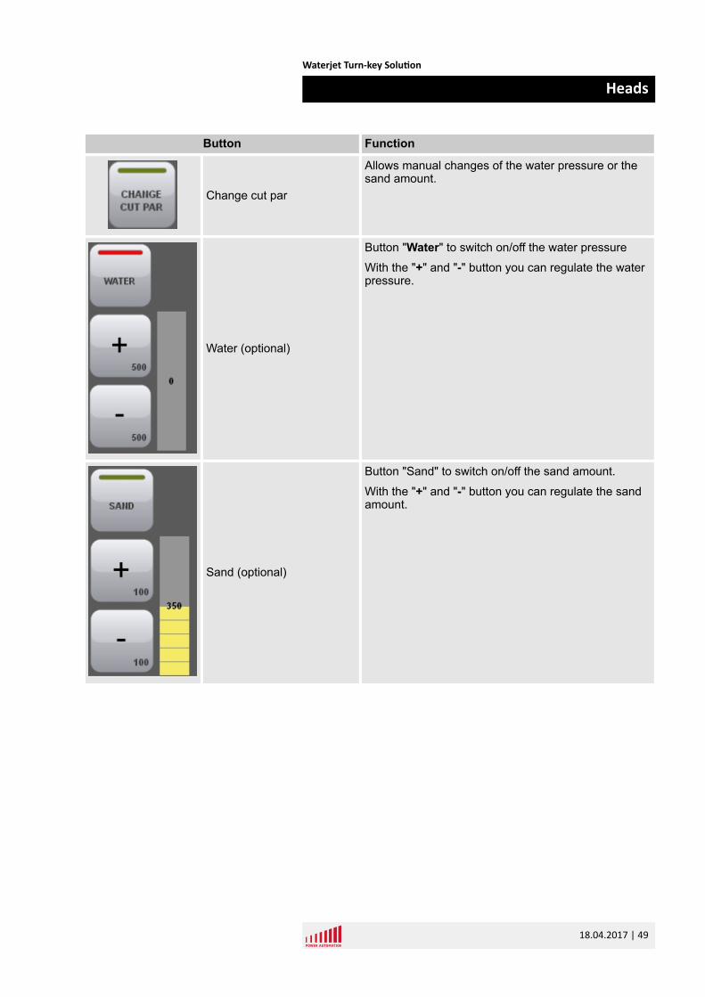
Change cut par
Allows manual changes of the water pressure or thesand amount.
Water (optional)
Button "Water" to switch on/off the water pressure
With the "+" and "-" button you can regulate the waterpressure.
Sand (optional)
Button "Sand" to switch on/off the sand amount.
With the "+" and "-" button you can regulate the sandamount.
Waterjet Turn-key Solution
Heads
18.04.2017 | 49

Waterjet Turn-key Solution
Heads
18.04.2017 | 50
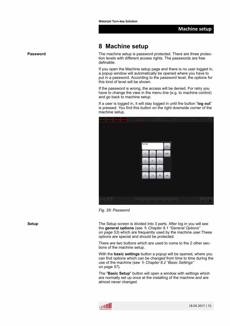
8 Machine setupThe machine setup is password protected. There are three protec-tion levels with different access rights. The passwords are freedefinable.
If you open the Machine setup page and there is no user logged in,a popup window will automatically be opened where you have toput in a password. According to the password level, the options forthis kind of level will be shown.
If the password is wrong, the access will be denied. For retry youhave to change the view in the menu line (e.g. to machine control)and go back to machine setup.
If a user is logged in, it will stay logged in until the button “log out”is pressed. You find this button on the right downside corner of themachine setup.
Fig. 29: Password
The Setup screen is divided into 3 parts. After log in you will seethe general options (see Ä Chapter 8.1 “General Options”on page 53) which are frequently used by the machine user.Theseoptions are special and should be protected.
There are two buttons which are used to come to the 2 other sec-tions of the machine setup.
With the basic settings button a popup will be opened, where youcan find options which can be changed from time to time during theuse of the machine (see Ä Chapter 8.2 “Basic Settings”on page 57).
The "Basic Setup" button will open a window with settings whichare normally set up once at the installing of the machine and arealmost never changed.
Password
Setup
Waterjet Turn-key Solution
Machine setup
18.04.2017 | 51
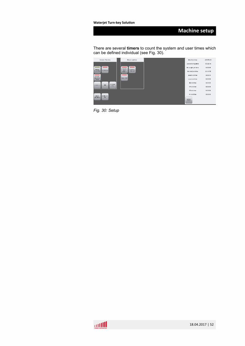
There are several timers to count the system and user times whichcan be defined individual (see Fig. 30).
Fig. 30: Setup
Waterjet Turn-key Solution
Machine setup
18.04.2017 | 52
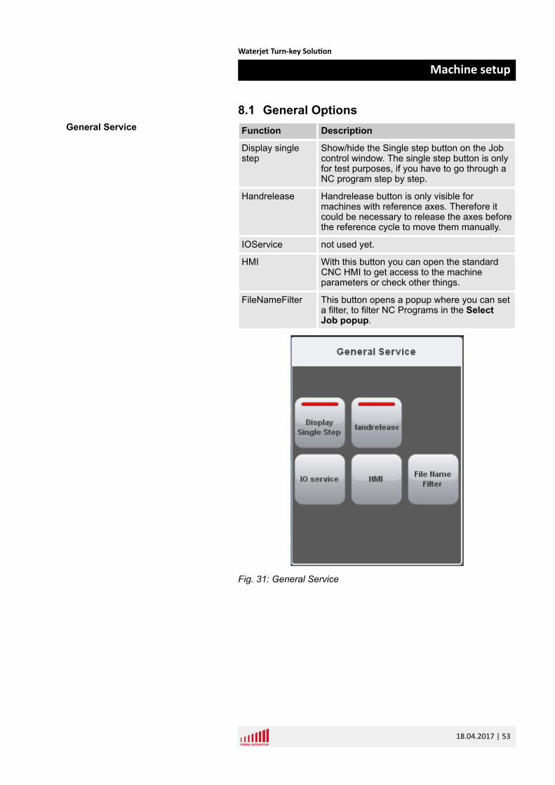
8.1 General OptionsFunction Description
Display singlestep
Show/hide the Single step button on the Jobcontrol window. The single step button is onlyfor test purposes, if you have to go through aNC program step by step.
Handrelease Handrelease button is only visible formachines with reference axes. Therefore itcould be necessary to release the axes beforethe reference cycle to move them manually.
IOService not used yet.
HMI With this button you can open the standardCNC HMI to get access to the machineparameters or check other things.
FileNameFilter This button opens a popup where you can seta filter, to filter NC Programs in the SelectJob popup.
Fig. 31: General Service
General Service
Waterjet Turn-key Solution
Machine setup
18.04.2017 | 53
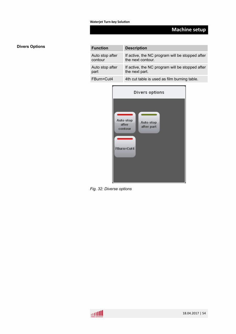
Function Description
Auto stop aftercontour
If active, the NC program will be stopped afterthe next contour.
Auto stop afterpart
If active, the NC program will be stopped afterthe next part.
FBurn=Cut4 4th cut table is used as film burning table.
Fig. 32: Diverse options
Divers Options
Waterjet Turn-key Solution
Machine setup
18.04.2017 | 54
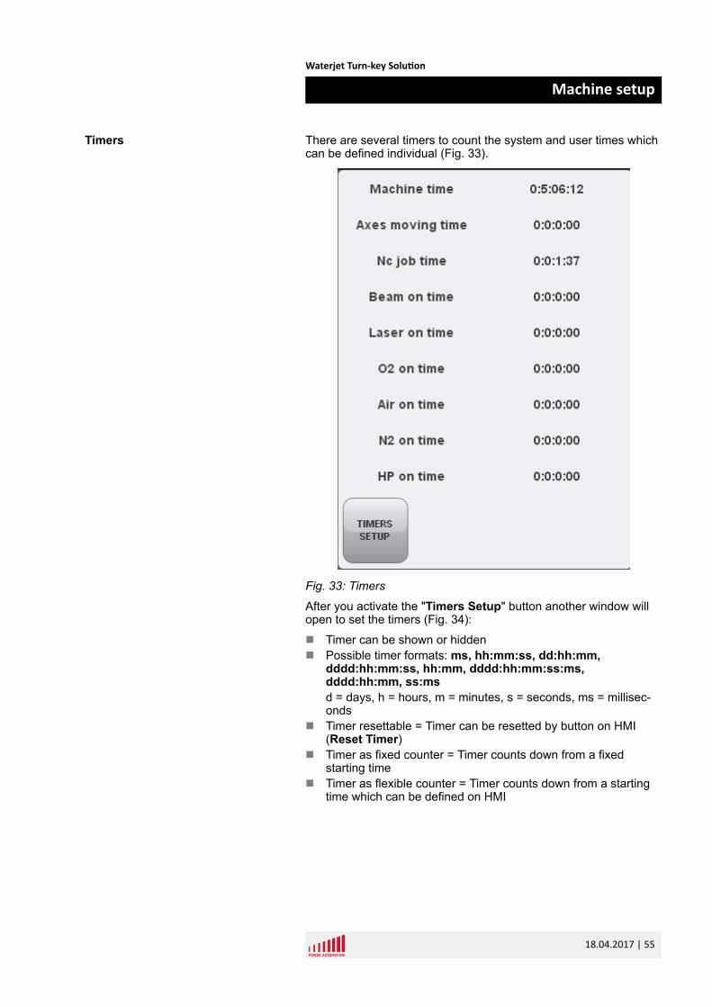
There are several timers to count the system and user times whichcan be defined individual (Fig. 33).
Fig. 33: Timers
After you activate the "Timers Setup" button another window willopen to set the timers (Fig. 34):
n Timer can be shown or hiddenn Possible timer formats: ms, hh:mm:ss, dd:hh:mm,
dddd:hh:mm:ss, hh:mm, dddd:hh:mm:ss:ms,dddd:hh:mm, ss:msd = days, h = hours, m = minutes, s = seconds, ms = millisec-onds
n Timer resettable = Timer can be resetted by button on HMI(Reset Timer)
n Timer as fixed counter = Timer counts down from a fixedstarting time
n Timer as flexible counter = Timer counts down from a startingtime which can be defined on HMI
Timers
Waterjet Turn-key Solution
Machine setup
18.04.2017 | 55
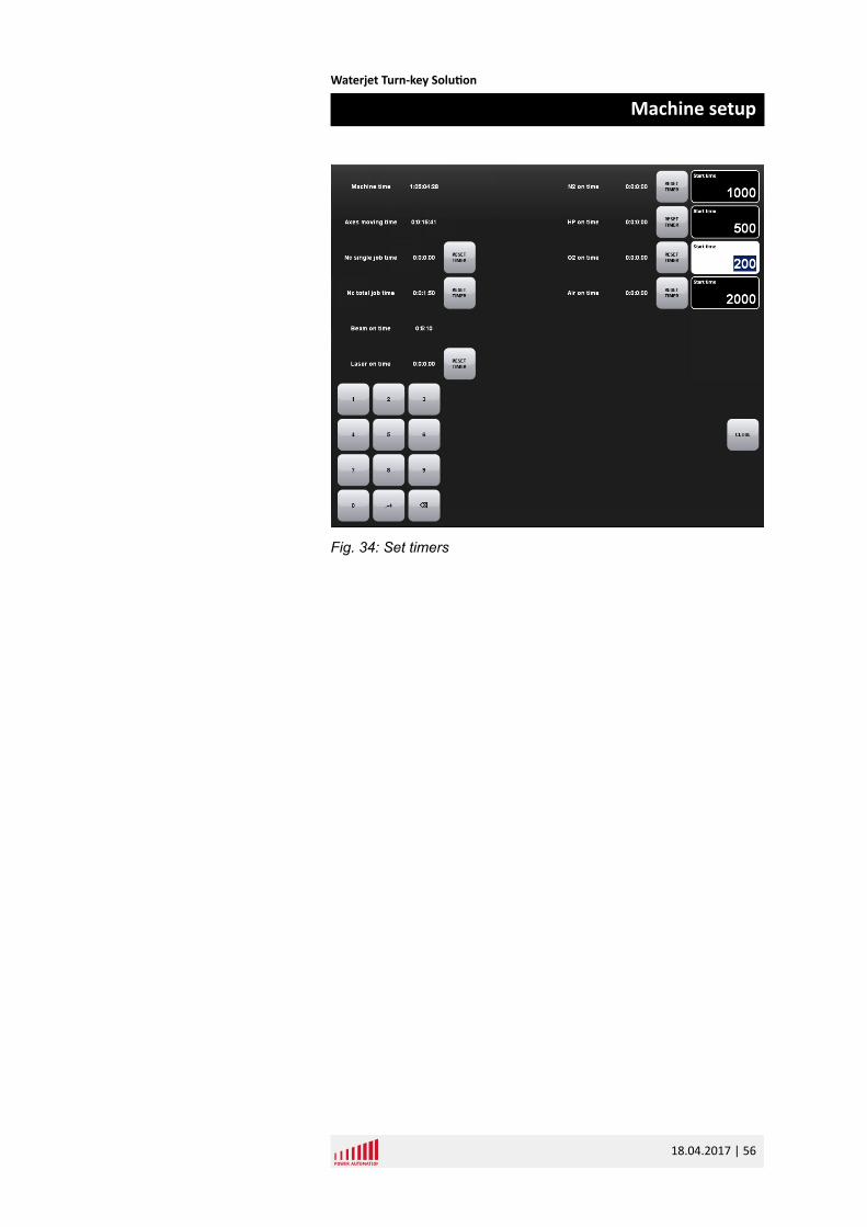
Fig. 34: Set timers
Waterjet Turn-key Solution
Machine setup
18.04.2017 | 56
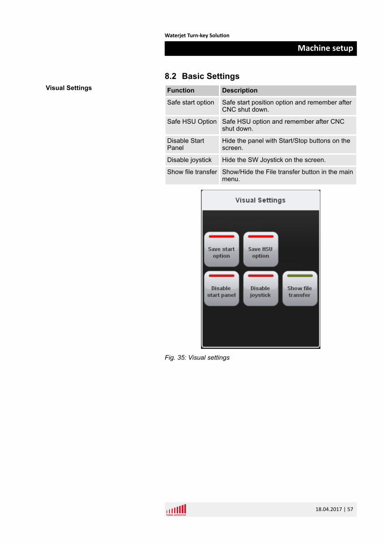
8.2 Basic SettingsFunction Description
Safe start option Safe start position option and remember afterCNC shut down.
Safe HSU Option Safe HSU option and remember after CNCshut down.
Disable StartPanel
Hide the panel with Start/Stop buttons on thescreen.
Disable joystick Hide the SW Joystick on the screen.
Show file transfer Show/Hide the File transfer button in the mainmenu.
Fig. 35: Visual settings
Visual Settings
Waterjet Turn-key Solution
Machine setup
18.04.2017 | 57
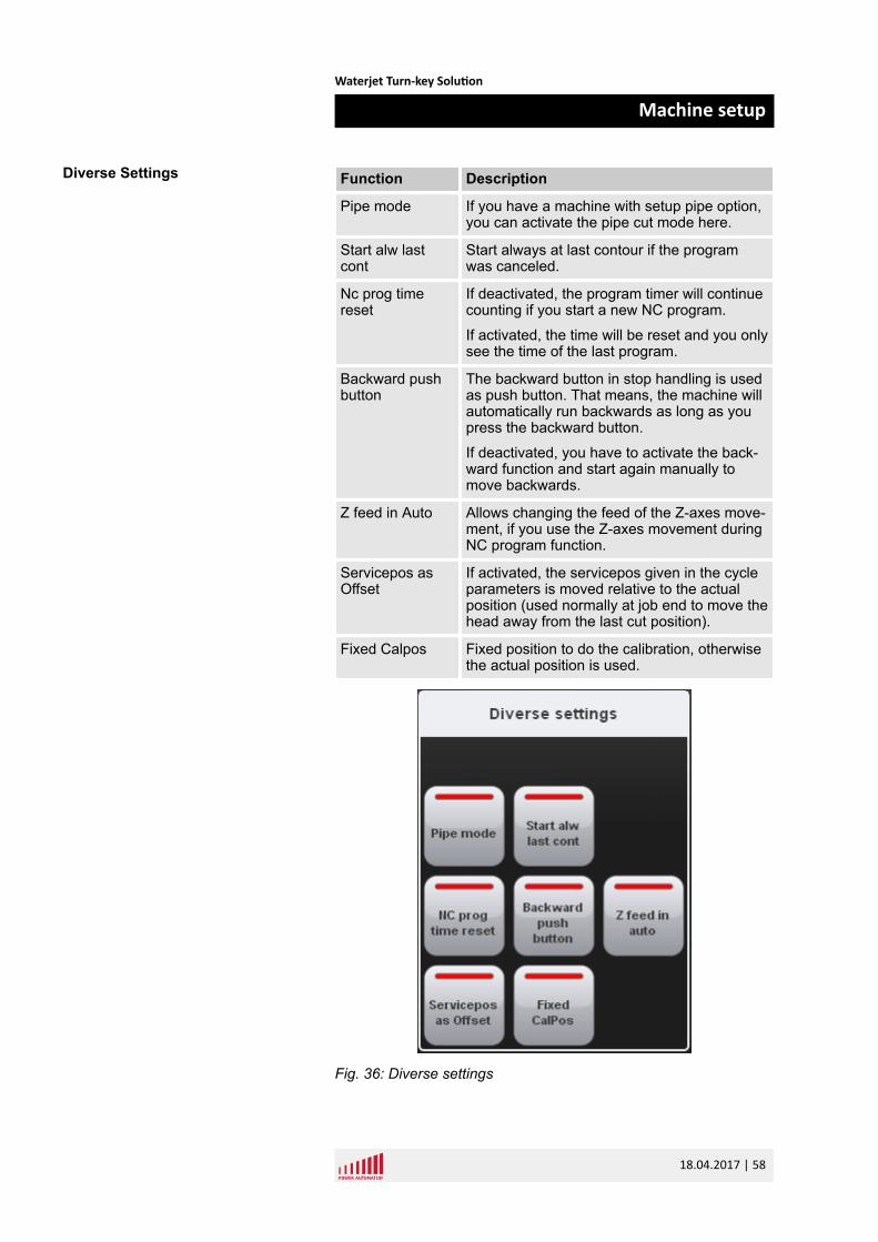
Function Description
Pipe mode If you have a machine with setup pipe option,you can activate the pipe cut mode here.
Start alw lastcont
Start always at last contour if the programwas canceled.
Nc prog timereset
If deactivated, the program timer will continuecounting if you start a new NC program.
If activated, the time will be reset and you onlysee the time of the last program.
Backward pushbutton
The backward button in stop handling is usedas push button. That means, the machine willautomatically run backwards as long as youpress the backward button.
If deactivated, you have to activate the back-ward function and start again manually tomove backwards.
Z feed in Auto Allows changing the feed of the Z-axes move-ment, if you use the Z-axes movement duringNC program function.
Servicepos asOffset
If activated, the servicepos given in the cycleparameters is moved relative to the actualposition (used normally at job end to move thehead away from the last cut position).
Fixed Calpos Fixed position to do the calibration, otherwisethe actual position is used.
Fig. 36: Diverse settings
Diverse Settings
Waterjet Turn-key Solution
Machine setup
18.04.2017 | 58
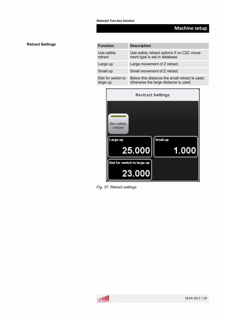
Function Description
Use safetyretract
Use safety retract options if no C2C move-ment type is set in database.
Large up Large movement of Z retract.
Small up Small movement of Z retract.
Dist for switch tolarge up
Below this distance the small retract is used,otherwise the large distance is used.
Fig. 37: Retract settings
Retract Settings
Waterjet Turn-key Solution
Machine setup
18.04.2017 | 59
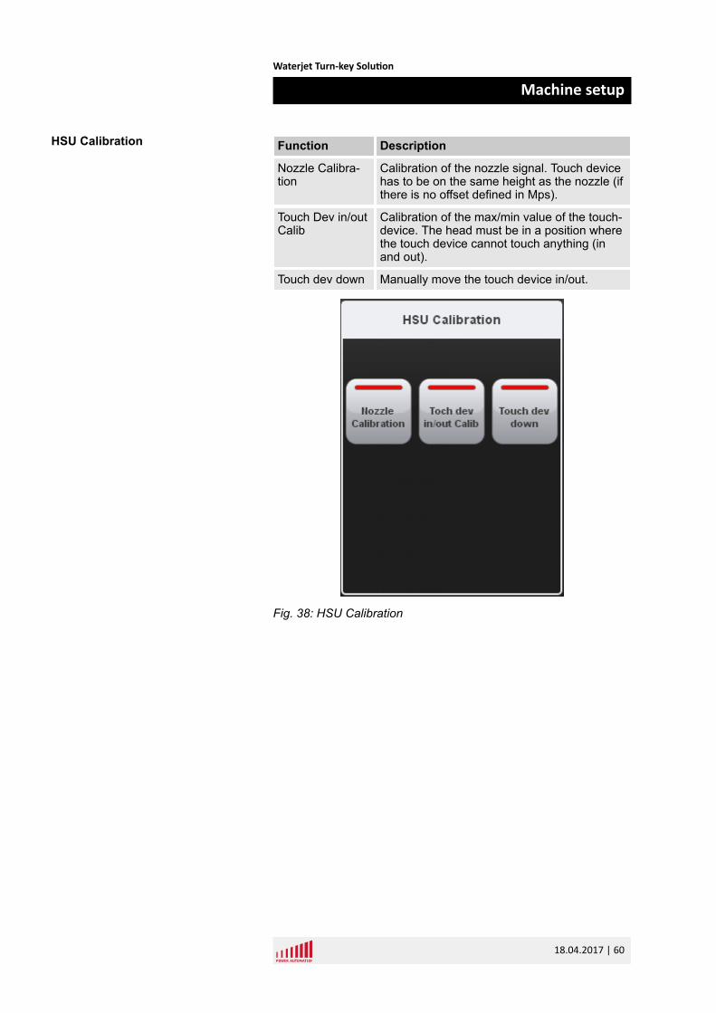
Function Description
Nozzle Calibra-tion
Calibration of the nozzle signal. Touch devicehas to be on the same height as the nozzle (ifthere is no offset defined in Mps).
Touch Dev in/outCalib
Calibration of the max/min value of the touch-device. The head must be in a position wherethe touch device cannot touch anything (inand out).
Touch dev down Manually move the touch device in/out.
Fig. 38: HSU Calibration
HSU Calibration
Waterjet Turn-key Solution
Machine setup
18.04.2017 | 60
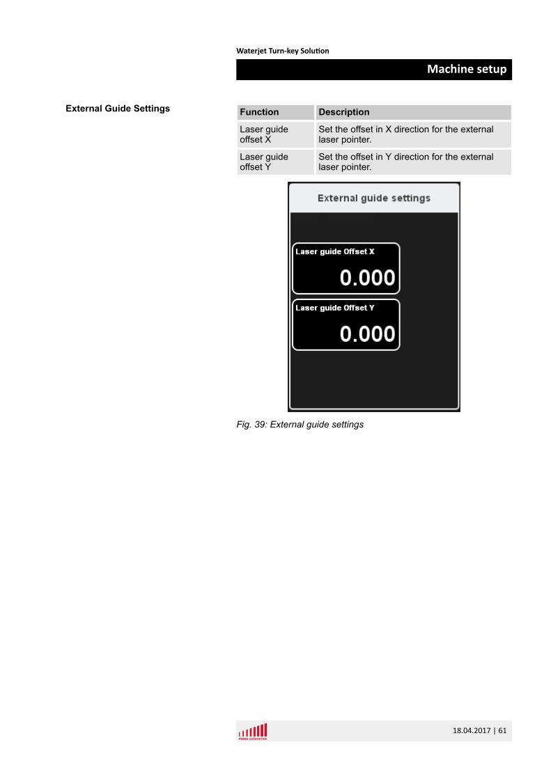
Function Description
Laser guideoffset X
Set the offset in X direction for the externallaser pointer.
Laser guideoffset Y
Set the offset in Y direction for the externallaser pointer.
Fig. 39: External guide settings
External Guide Settings
Waterjet Turn-key Solution
Machine setup
18.04.2017 | 61

Waterjet Turn-key Solution
Machine setup
18.04.2017 | 62
9 Service and return process9.1 ServiceBy PhonePA's well-educated service staff is available to answer your tech-nical questions. Due to the close co-operation with our customers,our engineers can solve problems often immediately by phone.
If on-site support is necessary, our service staff will diagnose theproblem and will prepare our field service engineer beforehand.This is to make on-site service as much effective as possible.
By Remote Control SoftwareEvery PA CNC is equipped with an Ethernet interface. If you havea network on-site, you only have to integrate the CNC system toyour network for world-wide-web access.
Power Automation provides a remote control software which allowsour service staff to log into your CNC. This provides all the informa-tion available on the machine. They can check all the data like thePLC program, machine parameters, or the NC programs directlyon the real system under real conditions. This is the fastest andmost cost-effective way to solve problems.
On-SiteIf necessary our service engineers will visit you to help you solveyour problems on-site. Our engineers are trained continuously tobe always up to date. Thereby you always can expect the bestsupport.
Due to our service centers worldwide, our service staff can be onsite normally within 24 hours at the latest.
Service At Power Automation
Waterjet Turn-key Solution
Service and return process
18.04.2017 | 63
9.1.1 Service addresses
Power Automation GmbH (Headquarters)Gottlieb-Daimler-Strasse 17/2
D-74385 Pleidelsheim
Tel: +49-7144-899-0
Fax: +49-7144-899-299
Power Automation America, Inc.8601 Jameel Road, Suite 140
Houston, Texas 77040 USA
Tel: +1-713-263-9400
Fax: +1-281-715-2500
Power Automation Office TurkeyKustepe Mah. Mecidiyekoy Yolu Cad.
Trump Towers No. 12 Kule: 2 K:18
Daire no: 3211022839 Sisli / Istanbul
Turkey
Tel: +90-212-306-3280
Fax: +90-212-306-3101
Shenzhen Double CNC Tech Co., Ltd8th Floor,WeiXinDa Building
Bao Min Road 2
Xi Xiang Town
Bao'an District, Shenzhen, Guangdong
PR China
Service Addresses
Waterjet Turn-key Solution
Service and return process
18.04.2017 | 64
Power Automation France SARLCité de la Photonique
Bâtiment Pléione
11 avenue Canteranne
33600 Pessac
France
Tel: +33-559-4010-50
Fax: +33-559-4010-59
ACE AutomationA-721, Twinrex B/D
Deokpungdong-ro 111-10, Hanam-si
Gyeonggi-do, 465-831
South Korea
9.2 Spare partsDue to the high quality of our products we can assure you that youwill not need this service often. Spare parts are often urgent soPower Automation provides the relevant spare parts at the localservice centers for immediate dispatch.
Our 3 service centers in Europe, North America and Asia allow usto deliver all needed parts typically within 24 hours.
Only trust PA's original parts - because every part passes our tightquality checks.
We also offer consulting services to identify the most critical partsfor the machines in your production facilities. We suggest what crit-ical stock may be required to ensure a minimum downtime of yourmachines. Our specialists look for common parts to keep yourinventory levels at a minimum.
Spare Parts
Waterjet Turn-key Solution
Service and return process
18.04.2017 | 65
9.3 Return policy and procedure
Power Automation will only accept control unitsand components for replacement or repair, if theyhave been returned in adherence to the provisionsgiven below.
n If material warranty is void or if no error is detected, a testingflat rate will be charged. If an error is determined, the testingflat rate will be charged to the repair costs.
n If material warranty is void you will receive a repair offer.n Before the repair starts we need a repair order from you, if the
material warranty is extinguished.
1. Contact Power Automation to receive an RMA form in Excelformat. Ä “RMA Form” on page 67
2. Open the 'RMA Process' form provided by Power Automa-tion.
Use one form for each single part you want to ship back toPower Automation.
3. Fill in the form.
The fields marked with a red star (*) are mandatory fields.
Only fill in the fields next to the yellow bar on the left side ofthe form.
Do not fill in the fields next to the blue bar on the left side ofthe form. These fields are for internal notes only and blocked.
4. Send the completed form as an Excel file by email [email protected] to your local support (seewebpage).
ð We will check the data and send the form back to you asa PDF file including an RMA number or tell you whatinformation is missing if necessary.
5. Print the RMA form and add it to the accompanying compo-nents and documents.
6. After the check and repair the components will be shipped toyou immediately.
Policy
Acquiring RMA Number
Waterjet Turn-key Solution
Service and return process
18.04.2017 | 66
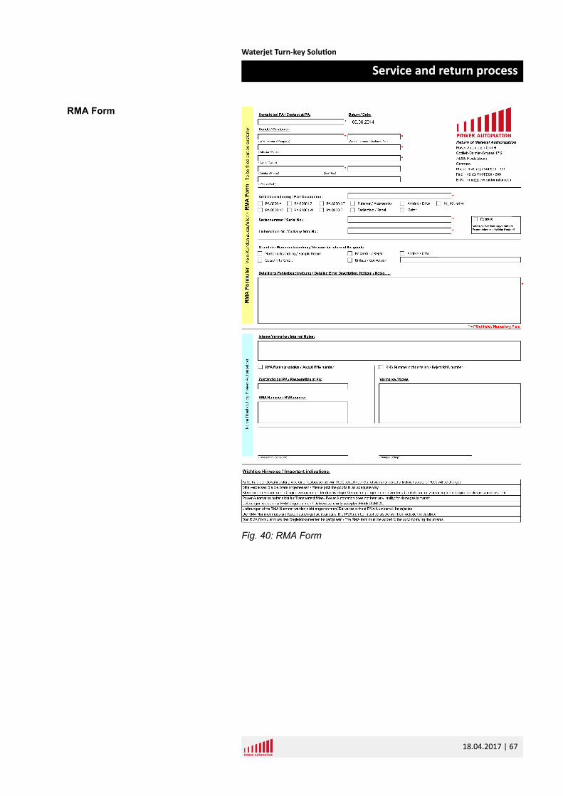
Fig. 40: RMA Form
RMA Form
Waterjet Turn-key Solution
Service and return process
18.04.2017 | 67
1. Pack the goods properly.
Controls must be packed in original or equivalent packaging.If the packaging is not proper, Power Automation will chargea packaging flat rate.
NOTICE!Damages due to inadequate packagingInadequate packaging may result in dam-ages to the control unit. This will void thematerial warranty. PA does not bear any lia-bilities for damages in transit.
2. Write the RMA number on the cardboard box clearly read-able from outside.
The incoming goods department rejects all deliverieswithout a visible, valid RMA number.
3. Ship the goods FREE DOMICILE / DDU. Other deliveries willbe rejected.
The goods have to arrive within 4 weeks after the date of theapproved RMA form.
9.4 TrainingHaving the best CNCs is one thing, to bring out the best of it is theother.
The PA training program comprises of a number of individuallycombinable training modules which offer you a well-founded knowl-edge for using PA CNCs. At our training centers we bring youremployees - beginners and experts- up to scratch in CNC tech-nology. We also offer individual training courses at your site. Thecontents of the courses will be customized to your requirements.
For more information see Ä Chapter 9.1.1 “Service addresses”on page 64.
Return
Conditions Of Supply
Training Courses
Waterjet Turn-key Solution
Service and return process
18.04.2017 | 68
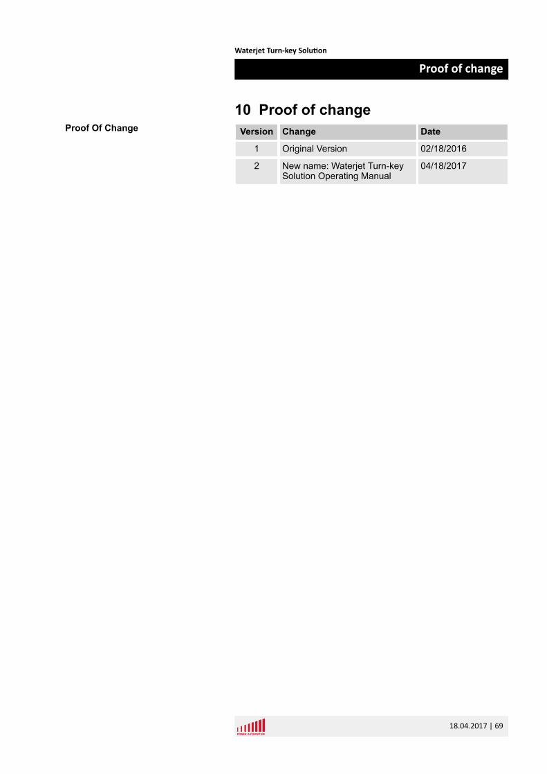
10 Proof of changeVersion Change Date
1 Original Version 02/18/2016
2 New name: Waterjet Turn-keySolution Operating Manual
04/18/2017
Proof Of Change
Waterjet Turn-key Solution
Proof of change
18.04.2017 | 69

Waterjet Turn-key Solution
Proof of change
18.04.2017 | 70
11 Index
EError window . . . . . . . . . . . . . . . . . . . . . . . . . . . . 14
FFeed Override . . . . . . . . . . . . . . . . . . . . . . . . . . . 10File Transfer . . . . . . . . . . . . . . . . . . . . . . . . . . . . 45
HHeads . . . . . . . . . . . . . . . . . . . . . . . . . . . . . . . . . 47
JJob Control . . . . . . . . . . . . . . . . . . . . . . . . . . . . . 25Job Control - Cycle off . . . . . . . . . . . . . . . . . . 25, 33Job Control - Cycle on
left side . . . . . . . . . . . . . . . . . . . . . . . . . . . . . 37right side . . . . . . . . . . . . . . . . . . . . . . . . . . . . 38
JobControlCycle Stop . . . . . . . . . . . . . . . . . . . . . . . . 40, 42
LLimitation of liability . . . . . . . . . . . . . . . . . . . . . . . . 7
MMachine Control Window . . . . . . . . . . . . . . . . . . 21Machine Movements . . . . . . . . . . . . . . . . . . . . . . 22Machine setup
General options . . . . . . . . . . . . . . . . . . . . . . . 53Main control bar . . . . . . . . . . . . . . . . . . . . . . . . . 10Manual jog options . . . . . . . . . . . . . . . . . . . . . . . 21Menu bar . . . . . . . . . . . . . . . . . . . . . . . . . . . . . . . 12
PPassword . . . . . . . . . . . . . . . . . . . . . . . . . . . . . . 51Path graphics window . . . . . . . . . . . . . . . . . . . . . 17Pictures
in the manual . . . . . . . . . . . . . . . . . . . . . . . . . . 5Proof of change . . . . . . . . . . . . . . . . . . . . . . . . . . 69Pump . . . . . . . . . . . . . . . . . . . . . . . . . . . . . . . . . 10
RRestart at contour . . . . . . . . . . . . . . . . . . . . . . . . 10
RMA form . . . . . . . . . . . . . . . . . . . . . . . . . . . . . . 67RMA-number . . . . . . . . . . . . . . . . . . . . . . . . . . . . 66
SSelect job . . . . . . . . . . . . . . . . . . . . . . . . . . . . . . 10Select Job . . . . . . . . . . . . . . . . . . . . . . . . . . . . . . 36Select sheet . . . . . . . . . . . . . . . . . . . . . . . . . . . . 10Service . . . . . . . . . . . . . . . . . . . . . . . . . . . . . . . . 63Service Addresses . . . . . . . . . . . . . . . . . . . . . . . 64Setup . . . . . . . . . . . . . . . . . . . . . . . . . . . . . . . . . 51Spare Parts . . . . . . . . . . . . . . . . . . . . . . . . . . . . . 65Status bar . . . . . . . . . . . . . . . . . . . . . . . . . . . . . . 11
TTest-run . . . . . . . . . . . . . . . . . . . . . . . . . . . . . . . . 10Timers . . . . . . . . . . . . . . . . . . . . . . . . . . . . . . . . . 55Training . . . . . . . . . . . . . . . . . . . . . . . . . . . . . . . . 68
WWater valve . . . . . . . . . . . . . . . . . . . . . . . . . . . . . 47
Waterjet Turn-key Solution
Index
18.04.2017 | 71
Related Documents