OPEN-FRAME GASOLINE GENERATING SET KGE2500X KGE4000X KGE6500X/E KGE6500X3/E3 KGE6500XW/EW SINGLE-PHASE: THREE-PHASE: WELDING & GENERATING SET:

Welcome message from author
This document is posted to help you gain knowledge. Please leave a comment to let me know what you think about it! Share it to your friends and learn new things together.
Transcript

OPEN-FRAME GASOLINE
GENERATING SET
KGE2500X
KGE4000X
KGE6500X/E
KGE6500X3/E3
KGE6500XW/EW
SINGLE-PHASE:
THREE-PHASE:
WELDING & GENERATING SET:
1. Safety information
2. Identification of components
3. Pre-operation check
4. Starting the generating set
5. Usage of the generating set
6. Stopping the generating set
7. Maintenance
8. Storage
9. Troubleshooting
10. Main technical specifications and data
11. Description of accumulator unit
12. Description of castor unit
13. Wiring diagram
14. Appendix
CONTENTS
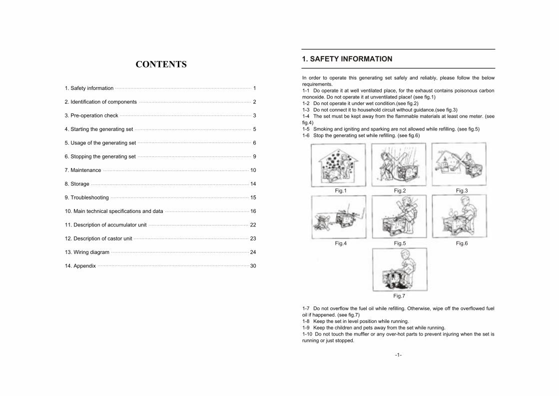
In order to operate this generating set safely and reliably, please follow the below
requirements.
1-1 Do operate it at well ventilated place, for the exhaust contains poisonous carbon
monoxide. Do not operate it at unventilated place! (see fig.1)
1-2 Do not operate it under wet condition.(see fig.2)
1-3 Do not connect it to household circuit without guidance.(see fig.3)
1-4 The set must be kept away from the flammable materials at least one meter. (see
fig.4)
1-5 Smoking and igniting and sparking are not allowed while refilling. (see fig.5)
1-6 Stop the generating set while refilling. (see fig.6)
1-7 Do not overflow the fuel oil while refilling. Otherwise, wipe off the overflowed fuel
oil if happened. (see fig.7)
1-8 Keep the set in level position while running.
1-9 Keep the children and pets away from the set while running.
1-10 Do not touch the muffler or any over-hot parts to prevent injuring when the set is
running or just stopped.
1. SAFETY INFORMATION
Fig.1 Fig.2 Fig.3
Fig.4 Fig.5 Fig.6
Fig.7
1
2
3
5
6
9
10
14
15
16
22
23
24
30
- -
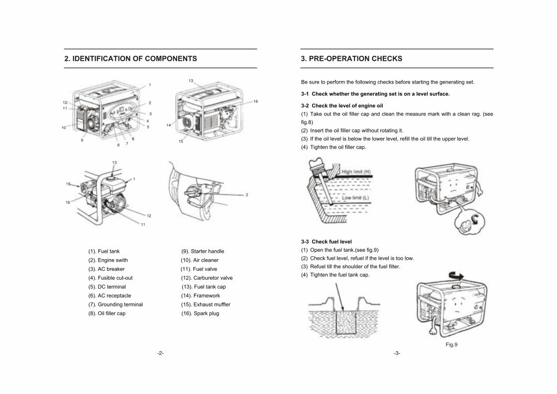
2. IDENTIFICATION OF COMPONENTS 3. PRE-OPERATION CHECKS
(1). Fuel tank (9). Starter handle
(2). Engine swith (10). Air cleaner
(3). AC breaker (11). Fuel valve
(4). Fusible cut-out (12). Carburetor valve
(5). DC terminal (13). Fuel tank cap
(6). AC receptacle (14). Framework
(7). Grounding terminal (15). Exhaust muffler
(8). Oil filler cap (16). Spark plug
Be sure to perform the following checks before starting the generating set.
3-1 Check whether the generating set is on a level surface.
3-2 Check the level of engine oil
(1) Take out the oil filler cap and clean the measure mark with a clean rag. (see
fig.8)
(2) Insert the oil filler cap without rotating it.
(3) If the oil level is below the lower level, refill the oil till the upper level.
(4) Tighten the oil filler cap.
3-3 Check fuel level
(1) Open the fuel tank.(see fig.9)
(2) Check fuel level, refuel if the level is too low.
(3) Refuel till the shoulder of the fuel filter.
(4) Tighten the fuel tank cap.
Fig.9
- -- -
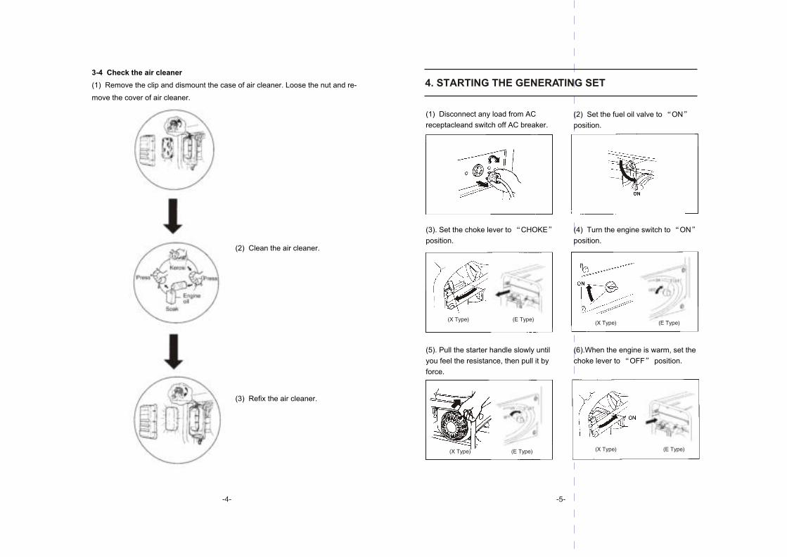
3-4 Check the air cleaner
(1) Remove the clip and dismount the case of air cleaner. Loose the nut and re-
move the cover of air cleaner.
(2) Clean the air cleaner.
(3) Refix the air cleaner.
4. STARTING THE GENERATING SET
(2) Set the fuel oil valve to ON
position.
(1) Disconnect any load from AC
receptacleand switch off AC breaker.
(6).When the engine is warm, set the
choke lever to OFF position.
(3). Set the choke lever to CHOKE
position.
(4) Turn the engine switch to ON
position.
(5). Pull the starter handle slowly until
you feel the resistance, then pull it by
force.
- -- -
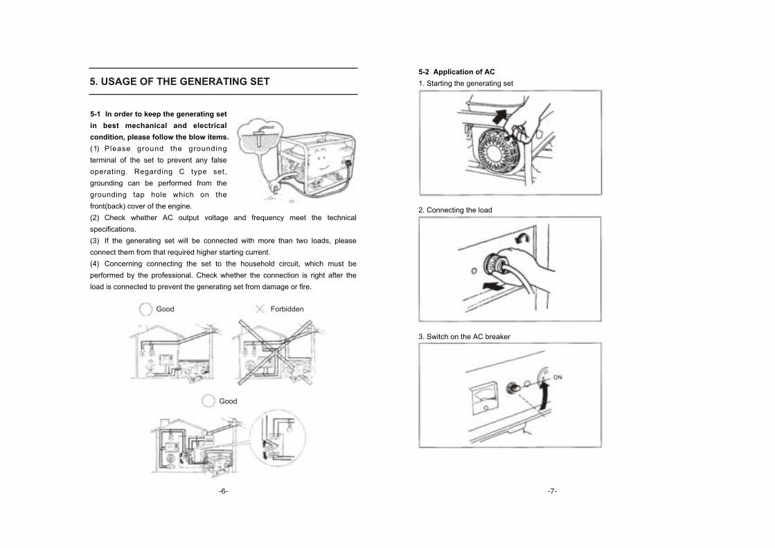
5-1 In order to keep the generating set
in best mechanical and electrical
condition, please follow the blow items.
(1) Please ground the grounding
terminal of the set to prevent any false
operating. Regarding C type set,
grounding can be performed from the
grounding tap hole which on the
front(back) cover of the engine.
(2) Check whether AC output voltage and frequency meet the technical
specifications.
(3) If the generating set will be connected with more than two loads, please
connect them from that required higher starting current.
(4) Concerning connecting the set to the household circuit, which must be
performed by the professional. Check whether the connection is right after the
load is connected to prevent the generating set from damage or fire.
5. USAGE OF THE GENERATING SET5-2 Application of AC
1. Starting the generating set
2. Connecting the load
3. Switch on the AC breaker
Good Forbidden
Good
- -- -

5-3 Electrical apparatus particularly motor-driven equipment will produce
very high current while starting, the below table provides the reference for
connecting these apparatus to the set.
Note: If you want to stop the engine in emergency, please set the engine switch
on OFF position.
6. STOPPING THE GENERATING SET
6-1 Switch off the AC breaker
6-2 Switch off the engine switch
6-3 Close the fuel valve
(X Type) (E Type)
(X/E Type)
- -- -
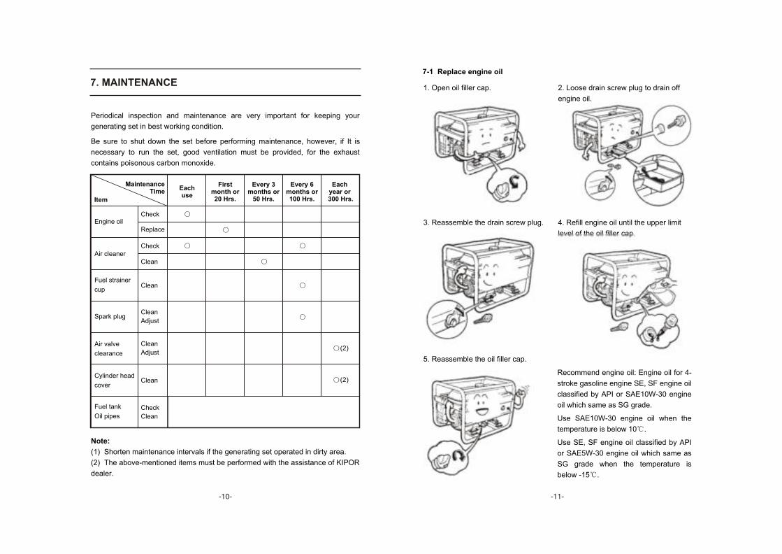
Periodical inspection and maintenance are very important for keeping your
generating set in best working condition.
Be sure to shut down the set before performing maintenance, however, if It is
necessary to run the set, good ventilation must be provided, for the exhaust
contains poisonous carbon monoxide.
7. MAINTENANCE
Note:
(1) Shorten maintenance intervals if the generating set operated in dirty area.
(2) The above-mentioned items must be performed with the assistance of KIPOR
dealer.
Recommend engine oil: Engine oil for 4-
stroke gasoline engine SE, SF engine oil
classified by API or SAE10W-30 engine
oil which same as SG grade.
Use SAE10W-30 engine oil when the
temperature is below 10 .
Use SE, SF engine oil classified by API
or SAE5W-30 engine oil which same as
SG grade when the temperature is
below -15 .
7-1 Replace engine oil
4. Refill engine oil until the upper limit
level of the oil filler cap.
1. Open oil filler cap. 2. Loose drain screw plug to drain off
engine oil.
3. Reassemble the drain screw plug.
5. Reassemble the oil filler cap.
Fuel tank
Oil pipes
Eachyear or
300 Hrs.
Eachuse
First month or 20 Hrs.
Every 3 months or
50 Hrs.
Every 6months or100 Hrs.
Check
Clean
Engine oil
Air cleaner
Fuel strainer
cup
Spark plug
Air valve
clearance
Cylinder head
cover
Check
Replace
Check
Clean
Clean
Clean
Adjust
Clean
Adjust
Clean (2)
(2)
Item
Maintenance Time
- -- -

7-2 Air cleaner (see 3-4)
7-3 Spark plug
7-4 Maintenance of the fuel filter
(1).Set the fuel valve on OFF position and dismount the fuel strainer cup.
1. Dismount spark plug cap
2. Dismount spark plug
(X/E Type) (C Type)
3. Clean the carbon
Post card 4. Test the clearanceof the spark plug
5. Reassembly the coverof spark plug
Dismount the fuel filter Blow it from the opposite directionof the arrow
(2) Clean the strainer cup thoroughly.
(3) Reassembly new rubber washer
and strainer cup tightly.
- -- -

8. STORAGE
2. Remove the filler cap and drain
screw plug, then drain off the
engine oil.
9. TROUBLESHOOTING
1. The generating set cannot start. 1. Remove the drain screw plug and
drain out gasoline from the carburetor.
3. Reassembly the drain
screw plug.
4. Untill the high limit of the filler
cap.
5. Pull out the starting handle
slowly untill you feel resistance.
2. Whether the engine switch is in
OFF position?
3. Check engine oil level. 4. Check fuel oil level.
5. Dismount the spark plug. 6. Check the spark plug.
(X/E Type) (C/L Type)
(X Type) (E Type)
- -- -
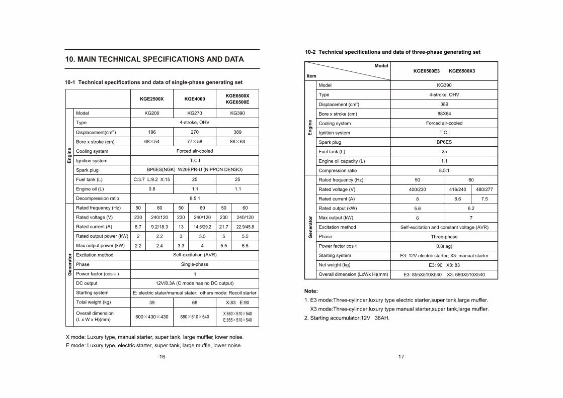
10-2 Technical specifications and data of three-phase generating set
Model
Type
3Displacement (cm )
Bore x stroke (cm)
Cooling system
Ignition system
Spark plug
Fuel tank (L)
Engine oil capacity (L)
Compression ratio
Rated frequency (Hz)
Rated voltage (V)
Rated current (A)
Rated output (kW)
Max output (kW)
Excitation method
Phase
Power factor cos
Starting system
Net weight (kg)
Overall dimension (LxWx H)(mm)
ItemKGE6500E3 KGE6500X3
Model
KG390
4-stroke, OHV
389
88X64
Forced air-cooled
T.C.I
BP6ES
25
1.1
8.5:1
Self-excitation and constant voltage (AVR)
Three-phase
0.8(lag)
E3: 12V electric starter; X3: manual starter
E3: 90 X3: 83
E3: 855X510X540 X3: 680X510X540
7
50
400/230
8
5.6
6
60
416/240
8.6
480/277
7.5
6.2
En
gin
eG
en
era
tor
Note:
1. E3 mode:Three-cylinder,luxury type electric starter,super tank,large muffler.
X3 mode:Three-cylinder,luxury type manual starter,super tank,large muffler.
2. Starting accumulator:12V 36AH.
- -
10. MAIN TECHNICAL SPECIFICATIONS AND DATA
10-1 Technical specifications and data of single-phase generating set
Overall dimension
(L x W x H)(mm)
En
gin
e
X:680 510 540
E:855 510 540
Ge
ne
rato
r
Model
Type
3 Displacement(cm )
Bore x stroke (cm)
Cooling system
Ignition system
Spark plug
Fuel tank (L)
Engine oil (L)
Decompression ratio
Rated frequency (Hz)
Rated voltage (V)
Rated current (A)
Rated output power (kW)
Max output power (kW)
Excitation method
Phase
Power factor (cos )
DC output
Starting system
Total weight (kg)
KGE2500X KGE4000KGE6500X
KGE6500E
KG200 KG270 KG390
4-stroke, OHV
196 270 389
68 54 77 58 88 64
Forced air-cooled
T.C.I
BP6ES(NGK) W20EPR-U (NIPPON DENSO)
2525
0.8 1.1 1.1
8.5:1
50 50 5060 60 60
230 240/120 240/120 240/120230 230
8.7 9.2/18.3 13 14.6/29.2 21.7 22.9/45.8
2 2.2 3 3.5 5 5.5
2.2 2.4 3.3 4 5.5 6.5
Self-excitation (AVR)
Single-phase
1
12V/8.3A (C mode has no DC output)
E: electric stater/manual stater; others mode: Recoil starter
39 68 X:83 E:90
600 430 430 680 510 540
X mode: Luxury type, manual starter, super tank, large muffler, lower noise.
E mode: Luxury type, electric starter, super tank, large muffle, lower noise.
- -
C:3.7 L:9.2 X:15

Explanation of three-phase generating set:
(1) Connect the loads to the generating set in order. As for the motor loads, start
the higher power motor first, and then start the lower after the former started. Be
sure not start them simultaneously. Any improper operation arouse, the
generating set will run sluggishly or halt, at this time, be sue to remove the loads
immediately and shut off the motor. Check whether overload happened or any
other faults. If overload made AC air breaker tripped, decrease the loads for
overload is not allowed. Wait some minutes before restart the generating set,
furthermore, do stop the set and make checks if any faults or abnormal
phenomenon still existed.
(2) If both of motor loads and inductive loads (e.g. Incandescent) are connected
to the generating set, first start motor loads and then inductive loads, otherwise,
starting motor loads will be difficult.
(3) Pay more attention to voltage of three phases while running. If the imbalance
of voltage of three phases exceeds 10%, do stop the set and make checks, and
then readjust three phase loads. Keep three phase loads in balance, the
imbalance cannot exceeds 20%. Meanwhile, the total load cannot exceeds rated
load, even the load of each phase cannot exceeds rated phase load, that is 1/3 of
rated load. Furthermore, the current of each phase cannot over rated current.
The sequence of output terminalsA,B,C,O(or U,V,W,N) of three-phase generating
set is from left to right or clockwise direction.
The bellow figure is the phase sequence of three-phase, five-hole-receptacle on
the output panel:
10-3 Technical specifications and data of welding&generating set
ItemKGE6500EW KGE6500XW
Model
Model
Type
3Displacement (cm )
Bore x stroke (cm)
Cooling system
Ignition system
Spark plug
Fuel tank capacity (L)
Lube oil capacity (L)
Compression ratio
Rated frequency (Hz)
Rated output (kW)
Rated voltage (V)
Rated current (A)
Phase
Power factor
Rated welding current (A)
Working voltage (V)
Load continuous rate
Current adjustment range (A)
Welding voltage at zero load (V)
Rated speed(r/min)
Excitation method
Starting system
Structure
Net weight (kg)
Overall dimension
(L W H)(mm)
We
ldin
g (
DC
)G
en
era
tin
g (
AC
)
We
ldin
g&
ge
ne
rati
ng
se
tE
ng
ine
KG390
4-stroke, OHV
389
88x64
Forced air-cooled
T.C.I
BP6ES
25
1.1
8.5:1
Single-phase
1.0
60-70
140
26
50%-140A
50-190
Generating:3000; welding:3600 3600
Dual excitation
EW: 12V electric starter XW: manual starter
Open frame type
EW:95 XW:88
EW:855 510 540
XW:680 510 540
60
2.2
240
9.2
50
2
230
8.7
- -- -
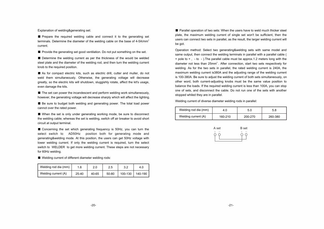
Explanation of welding&generating set:
Prepare the required welding cable and connect it to the generating set 2 terminals. Determine the diameter of the welding cable on the base of 4-5A/mm
current.
Provide the generating set good ventilation. Do not put something on the set.
Determine the welding current as per the thickness of the would be welded
steel plate and the diameter of the welding rod, and then turn the welding current
knob to the required position.
As for compact electric kits, such as electric drill, cutter and muller, do not
weld them simultaneously. Otherwise, the generating voltage will decrease
greatly, so the electric kits will shutdown, sluggishly rotate, affect the kit's usage,
even damage the kits.
The set can power the incandescent and perform welding work simultaneously,
however, the generating voltage will decrease sharply which will affect the lighting.
Be sure to budget both welding and generating power. The total load power
cannot over the rated power.
When the set is only under generating working mode, be sure to disconnect
the welding cable; whereas the set is welding, switch off air breaker to avoid short
circuit at output terminal.
Concerning the set which generating frequency is 50Hz, you can turn the
select switch to AD50Hz position both for generating mode and
generating&welding mode. At this position, the users can get 50Hz voltage with
lower welding current. If only the welding current is required, turn the select
switch to WELDER to get more welding current. These steps are not necessary
for 60Hz welding.
Welding current of different diameter welding rods:
Parallel operation of two sets: When the users have to weld much thicker steel
plate, the maximum welding current of single set won't be sufficient, then the
users can connect two sets in parallel, as the result, the larger welding current will
be got.
Operation method: Select two generating&welding sets with same model and
same output, then connect the welding terminals in parallel with a parallel cable (
+ pole to + , - to - ).The parallel cable must be approx.1.2 meters long with the 2 diameter not less than 25mm . After connection, start two sets respectively for
welding. As for the two sets in parallel, the rated welding current is 240A, the
maximum welding current is380A and the adjusting range of the welding current
is 100-380A. Be sure to adjust the welding current of both sets simultaneously, on
other word, both current-adjusting knobs must be the same value position to
balance the loads. If the required welding current is less than 100A, you can stop
one of sets, and disconnect the cable. Do not run one of the sets with another
stopped whiled they are in parallel.
Welding current of diverse diameter welding rods in parallel:
140-190
Welding rod dia (mm)
Welding current (A)
1.6 2.0 2.5 3.2 4.0
25-40 40-65 50-80 100-130
260-380Welding current (A)
Welding rod dia (mm) 4.0 5.0 5.8
160-210 200-270
A set B set
- -- -
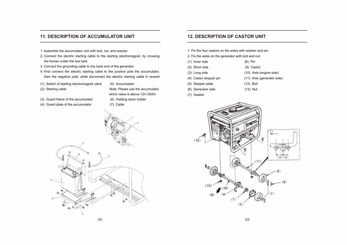
11. DESCRIPTION OF ACCUMULATOR UNIT
1. Assemble the accumulator unit with bolt, nut, and washer.
2. Connect the electric starting cable to the starting electromagnet, by crossing
the former under the fuel tank.
3. Connect the grounding cable to the back end of the generator.
4. First connect the electric starting cable to the positive pole the accumulator,
then the negative pole, while disconnect the electric starting cable in reverst
(1) Switch of starting electromagnet valve (5) Accumulator
(2) Starting cable Note: Please use the accumulator
which value is above 12V-35AH
(3) Guard frame of the accumulator (6) Holding down holder
(4) Guard plate of the accumulator (7) Cable
12. DESCRIPTION OF CASTOR UNIT
1. Fix the four castors on the axles with washer and pin.
2. Fix the axles on the generator with bolt and nut.
(1) Inner side (8) Pin
(2) Short side (9) Castor
(3) Long side (10) Axle (engine side)
(4) Castor stopper pin (11) Axle (generator side)
(5) Stopper plate (12) Bolt
(6) Generator side (13) Nut
(7) Gasket
- -- -
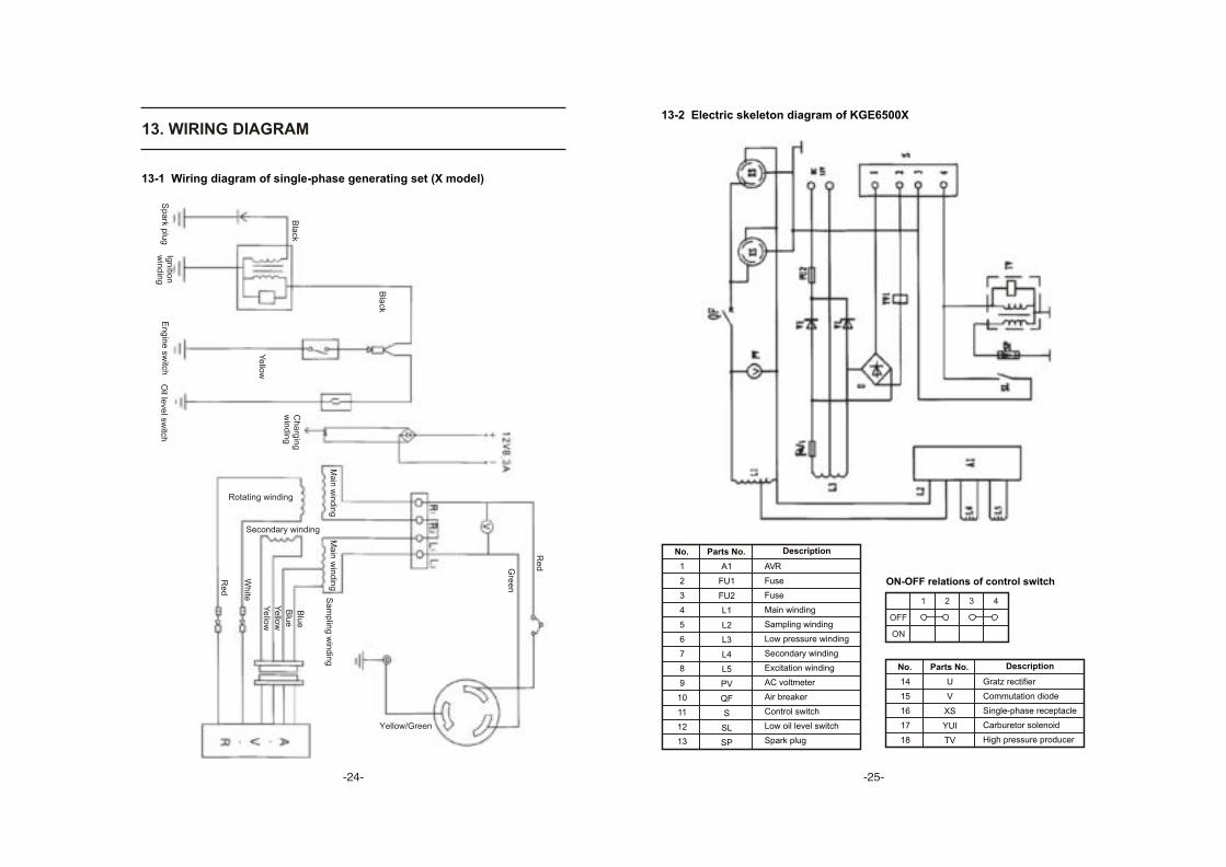
13. WIRING DIAGRAM13-2 Electric skeleton diagram of KGE6500X
No. DescriptionParts No.
1
2
3
4
5
6
7
8
9
10
11
12
13
A1
FU1
FU2
L1
L2
L3
L4
L5
PV
QF
S
SL
SP
AVR
Fuse
Fuse
Main winding
Sampling winding
Low pressure winding
Secondary winding
Excitation winding
AC voltmeter
Air breaker
Control switch
Low oil level switch
Spark plug
No. DescriptionParts No.
14
15
16
17
18
U
V
XS
YUI
TV
Gratz rectifier
Commutation diode
Single-phase receptacle
Carburetor solenoid
High pressure producer
ON-OFF relations of control switch
OFF
ON
1 2 3 4
13-1 Wiring diagram of single-phase generating set (X model)
Sp
ark p
lug
Ign
ition
win
din
gE
ng
ine
switch
Oil le
vel sw
itch
Bla
ck
Bla
ck
Ye
llow
Ch
arg
ing
win
din
g
Secondary winding
Ma
in w
ind
ing
Ma
in w
ind
ing
Sa
mp
ling
win
din
g
Blu
e
Blu
e
Ye
llow
Ye
llow
Wh
ite
Re
d
Yellow/Green
Re
dGre
en
Rotating winding
- -- -
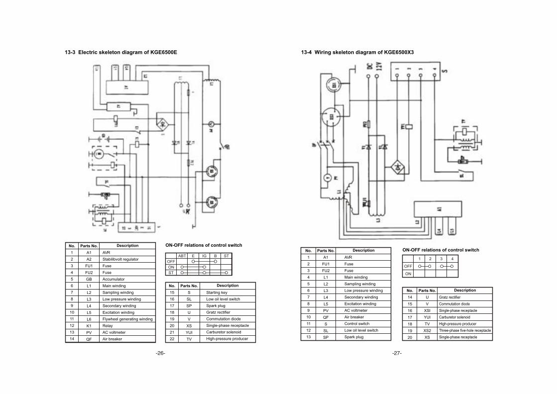
13-3 Electric skeleton diagram of KGE6500E
ON-OFF relations of control switch
No. DescriptionParts No.
15
16
17
18
19
20
21
22
S
SL
SP
U
V
XS
YUI
TV
Starting key
Low oil level switch
Spark plug
Gratz rectifier
Commutation diode
Single-phase receptacle
Carburetor solenoid
High-pressure producer
No. DescriptionParts No.
1
2
3
4
5
6
7
8
9
10
11
12
13
14
A1
A2
FU1
FU2
GB
L1
L2
L3
L4
L5
L6
K1
PV
QF
AVR
Stabilibvolt regulator
Fuse
Fuse
Accumulator
Main winding
Sampling winding
Low pressure winding
Secondary winding
Excitation winding
Flywheel generating winding
Relay
AC voltmeter
Air breaker
OFF
ON
ABT E IG B ST
ST
13-4 Wiring skeleton diagram of KGE6500X3
No. DescriptionParts No.
14
15
16
17
18
19
20
U
V
XSI
YUI
TV
XS2
XS
Gratz rectifier
Commutation diode
Single-phase receptacle
Carburetor solenoid
High-pressure producer
Three-phase five-hole receptacle
Single-phase receptacle
ON-OFF relations of control switch
OFF
ON
1 2 3 4
No. DescriptionParts No.
1
2
3
4
5
6
7
8
9
10
11
12
13
A1
FU1
FU2
L1
L2
L3
L4
L5
PV
QF
S
SL
SP
AVR
Fuse
Fuse
Main winding
Sampling winding
Low pressure winding
Secondary winding
Excitation winding
AC voltmeter
Air breaker
Control switch
Low oil level switch
Spark plug
- -- -

ON-OFF relations of control switch
No. DescriptionParts No.
15
16
17
18
19
20
21
22
S
SL
SP
U
V
XS
YUI
TV
Starting key
Low oil level switch
Spark plug
Gratz rectifier
Commutation diode
Single-phase receptacle
Carburetor solenoid
High-pressure producer
No. DescriptionParts No.
1
2
3
4
5
6
7
8
9
10
11
12
13
14
A1
A2
FU1
FU2
GB
L1
L2
L3
L4
L5
L6
K1
PV
QF
AVR
Stabilibvolt regulator
Fuse
Fuse
Accumulator
Main winding
Sampling winding
Low pressure winding
Secondary winding
Excitation winding
Flywheel generating winding
Relay
AC voltmeter
Air breaker
OFF
ON
ABT E IG B ST
ST
13-5 Electric skeleton diagram of KGE6500E3
No. DescriptionParts No.
17
18
19
20
21
22
23
24
25
26
27
28
29
30
31
32
OLSW
R
RP
SP
S1
S2
V1
V2
V3
V4
V5
QF
XS
YV1
YV2
MG
Low oil level switch
Resistance
Adjustable resistance
Spark plug
Select switch
Select switch
Commutation diode
Commutation diode
Gratz rectifier
Gratz rectifier
Gratz rectifier
Air breaker
AC single-phase receptacle
Carburetor solenoid
Throttle solenoid
Generating winding
No. DescriptionParts No.
1
2
3
4
5
6
7
8
9
10
11
12
13
14
15
16
A4
SUTO
C
FU
GB
HL
IG
K
M
M1
M1
M2
M3
M5
MG
L
Current inducing modular
Auto switch
Capacitance
Fuse
Accumulator
Working indicator light
Ignition coil
Relay
Start motor
Flywheel charging winding
Bucking winding
Main winding
Secondary winding
Excitation winding
Generating winding
Induction
13-6 Electric skeleton diagram of KGE6500XW/KGE6500EW
Note: EW model is electric starter type, XW model is recoil starter type. There's
no components inside invisible A frame for XW model, other components same
as EW model.
- -- -

14. APPENDIX
NO. REMARKNAME QUANTITY
1
2
Generator
Electric plug receptacle
1
1/2
Packing list
NO. REMARKNAME QUANTITY
1
2
3
4
5
Gasoline generator set operation manual
Gasoline engine operation manual
Gasoline engine parts diagram
Certificate of quality
1
1
1
1
1
Number of controlbox socket
- -
Related Documents