Integration Guide AudioCodes One Voice™ Operations Center (OC) One Voice Operations Center Integration with Northbound Interfaces Version 7.4

Welcome message from author
This document is posted to help you gain knowledge. Please leave a comment to let me know what you think about it! Share it to your friends and learn new things together.
Transcript
Integration Guide AudioCodes One Voice™ Operations Center (OC)
One Voice Operations Center Integration with Northbound Interfaces
Version 7.4

Integration Guide Contents
Version 7.4 3 One Voice Operations Center
Table of Contents
1 Overview .............................................................................................................. 7
2 OC Integration ..................................................................................................... 9
2.1 OC Integration Elements ......................................................................... 10 2.1.1 OC Topology File ................................................................................... 10 2.1.2 Alarms .................................................................................................... 10 2.1.3 Gateway Status ...................................................................................... 10 2.1.4 Security .................................................................................................. 10 2.1.5 Configuration and Maintenance .............................................................. 10
2.2 NBIF Folder .............................................................................................. 11
3 Topology Files ................................................................................................... 15
3.1 MGs Topology List .................................................................................. 15 3.2 Topology.xml File .................................................................................... 17
4 Fault Management ............................................................................................. 19
4.1 Alarms and Events Forwarding to the NMS .......................................... 19 4.1.1 Forwarding Alarms from OC Server to the NMS ..................................... 21 4.1.2 Forwarding Alarms Directly from Devices to NMS .................................. 26
4.2 OC Server Alarm Settings ....................................................................... 26 4.2.1 Alarms Automatic Clearing (on Startup) ................................................. 26 4.2.2 Alarms Automatic Clearing Period (Days)............................................... 26 4.2.3 Events Clearing Mechanism ................................................................... 27 4.2.4 Alarm Suppression Mechanism .............................................................. 27 4.2.5 Alarms Sequence Numbering ................................................................. 27 4.2.6 SNMP Alarms Synchronization ............................................................... 29 4.2.7 Resynchronization (Resync) Mechanism ................................................ 30 4.2.8 OC Keep-alive ........................................................................................ 33
4.3 Status / State Management via Devices SNMP Interface ..................... 35
5 Statistics Reports .............................................................................................. 37
6 OC Server Backup ............................................................................................. 39
7 Security .............................................................................................................. 41
7.1 Network Communication Protocols ....................................................... 41 7.2 OC User Identity Management ................................................................ 42
7.2.1 Authentication and Authorization using a Radius Server ........................ 43 7.2.1.1 Configuring Radius Server Client ........................................................43 7.2.1.2 Configuring RADIUS Server ................................................................45
7.2.2 Authentication and Authorization using an LDAP Server ........................ 47 7.3 HTTPS Connection .................................................................................. 48
Integration with Northbound Interfaces
Integration Guide 4 Document #: LTRT-19214
List of Figures Figure 2-1: OC Integration Overview ........................................................................................................ 9 Figure 2-2: NBIF Parent Directory ..........................................................................................................12 Figure 2-3: NBIF Topology Directory ......................................................................................................12 Figure 3-1: Topology File-Excel View .....................................................................................................16 Figure 4-1: Alarm and Event Forwarding ...............................................................................................20 Figure 4-2: Alarms – Forwarding – Topology Conditions .......................................................................21 Figure 4-3: Alarms – Forwarding – Rule Conditions ..............................................................................23 Figure 4-4: Alarms – Forwarding – Destination SNMPv3 ......................................................................24 Figure 4-5: Resync Flow .........................................................................................................................31 Figure 4-6: OC Keep-alive ......................................................................................................................33 Figure 4-7: Alarm Forwarding Configuration ..........................................................................................34 Figure 4-8: Alarms Forwarding Rule Dialog ...........................................................................................34 Figure 4-9: Destination Rule Configuration ............................................................................................35 Figure 5-1: Statistics Reports .................................................................................................................37 Figure 7-1: OC User Management ........................................................................................................42 Figure 7-2: RADIUS Authentication and Authorization ..........................................................................45 Figure 7-3: LDAP Authentication and Authorization ...............................................................................47
List of Tables Table 4-1: Forwarding Alarms – Topology Conditions - Parameter Descriptions ..................................21 Table 4-2: Forwarding Alarms – Rule Conditions - Parameter Descriptions .........................................23 Table 4-3: Forwarding Alarms – Destination ..........................................................................................25 Table 4-4: Forwarding Alarms - Destination - SNMP .............................................................................25 Table 4-5: Maximum Active Alarms according to Device .......................................................................28 Table 4-6: Maximum Active Alarms according to Device .......................................................................29
Integration Guide Notices
Version 7.4 5 One Voice Operations Center
Notice
Information contained in this document is believed to be accurate and reliable at the time of printing. However, due to ongoing product improvements and revisions, AudioCodes cannot guarantee accuracy of printed material after the Date Published nor can it accept responsibility for errors or omissions. Updates to this document and other documents including the most updated SW releases can be viewed by registered customers http://www.audiocodes.com/downloads.
This document is subject to change without notice.
Date Published: October-22-2017
WEEE EU Directive
Pursuant to the WEEE EU Directive, electronic and electrical waste must not be disposed of with unsorted waste. Please contact your local recycling authority for disposal of this product.
Customer Support
Customer technical support and services are provided by AudioCodes or by an authorized AudioCodes Service Partner. For more information on how to buy technical support for AudioCodes products and for contact information, please visit our Web site at www.audiocodes.com/support.
Documentation Feedback
AudioCodes continually strives to produce high quality documentation. If you have any comments (suggestions or errors) regarding this document, please fill out the Documentation Feedback form on our Web site at http://www.audiocodes.com/downloads.
Document Revision Record
LTRT Description
19214 Initial document release for Version 7.4.

Integration with Northbound Interfaces
Integration Guide 6 Document #: LTRT-19214
This page is intentionally left blank.
Integration Guide 1. Overview
Version 7.4 7 One Voice Operations Center
1 Overview AudioCodes One Voice Operations Center (OC) delivers a comprehensive management tools suite comprising of base platform and add-on modular applications for the management, monitoring and operation of converged VoIP and data networks implemented in large-scale cloud or premise-based unified communications deployments using AudioCodes devices. The products that are managed by the OC include the Session Border Controllers (SBC), Media Gateways, Microsoft Survivable Branch Appliances (SBA), Multi Service Business Router (MSBR), residential gateways and endpoints (IP Phones). The OC also integrates with the Microsoft Skype for Business environment platforms. The Network Operations Center's core product, the Operations Center OC manages these products in a centralized device inventory via a Web client, enabling integrative network operations. The following describes the key products in the OC suite:
The One Voice Operations Center (OC): The OC is an advanced solution for remote standards-based management of AudioCodes products within VoP networks, covering all areas vital for their efficient operation, administration, management and security. A single user interface provides real time information including network and device component status, activity logs and alarms. Complete End-to-End network control includes data on all devices, all locations, all sizes, all network functions and services and full control over the network, including services, updates, upgrades, and operations. The OC is in AudioCodes’ assessment, the best tool to manage AudioCodes devices. However, it does not replace the NMS and OSS management systems, which displays to operators a comprehensive view of the network, including other vendors’ equipment. After defining and initially provisioning a device via the device's embedded Web server tool, operators will usually work with an NMS / OSS for day-to-day maintenance. Only in the event of problems with a device or when significant maintenance tasks must be performed, will operators open the OC and work directly with it. Consequently, the OC provides APIs for faults monitoring (alarms) and security integration with a higher level management system.
Voice Quality Management: Voice Quality Management involves the analyze of real-time Voice Quality statistics, which enables the rapid identification of the metrics responsible for degradation in the quality of any VoIP call made over the network nodes including AudioCodes devices and links. It provides an accurate diagnostic and troubleshooting tool for analyzing quality problems in response to VoIP user criticism. It proactively prevents VoIP quality degradation and optimizes quality of experience for VoIP users. In addition, it integrates with Microsoft Skype for Business monitoring server to provide end-to-end VoIP quality monitoring on Microsoft Skype for Business deployments. In addition, Voice Quality integrates and monitors with endpoints reporting RFC 6035 SIP PUBLISH packets.

Integration with Northbound Interfaces
Integration Guide 8 Document #: LTRT-19214
The IP Phone Manager Pro:
AudioCodes' IP Phone Manager Pro enables enterprise network administrators to effortlessly and effectively set up, configure and update up to 30000 400HD Series IP phones in globally distributed corporations. These phones can upload configuration files from the OC server and send status updates over the REST protocol.
Integration Guide 2. OC Integration
Version 7.4 9 One Voice Operations Center
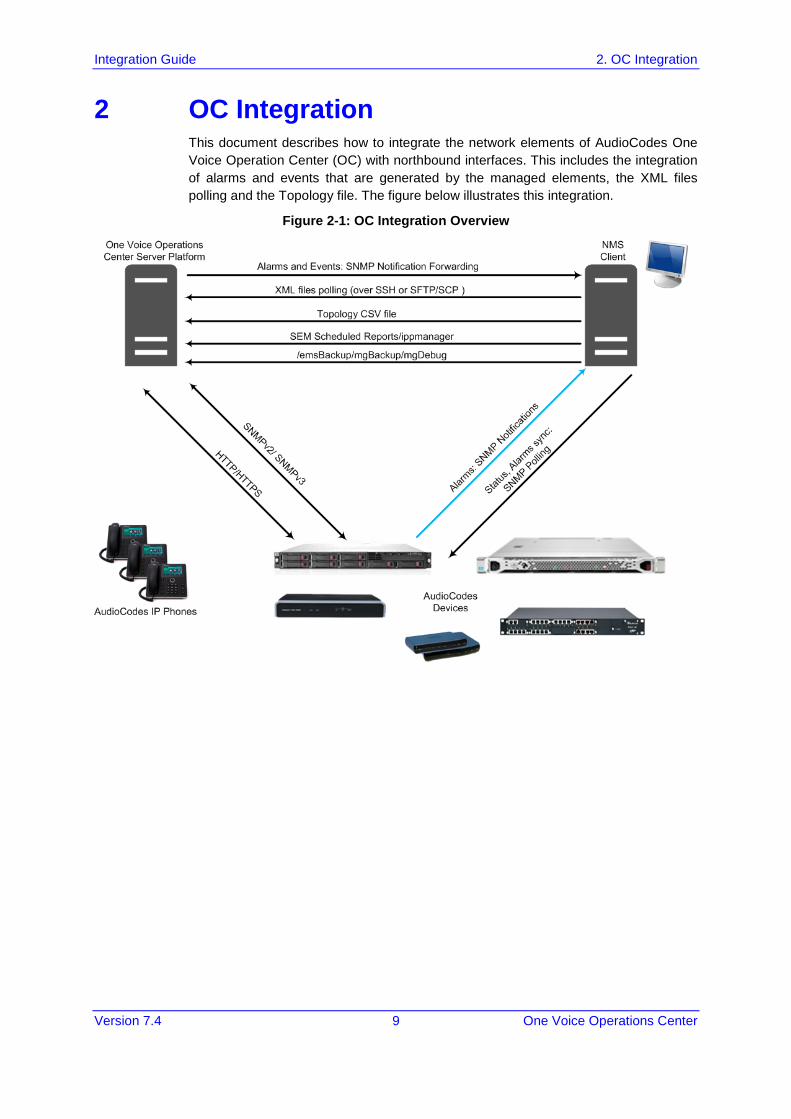
2 OC Integration This document describes how to integrate the network elements of AudioCodes One Voice Operation Center (OC) with northbound interfaces. This includes the integration of alarms and events that are generated by the managed elements, the XML files polling and the Topology file. The figure below illustrates this integration.
Figure 2-1: OC Integration Overview
Integration with Northbound Interfaces
Integration Guide 10 Document #: LTRT-19214
2.1 OC Integration Elements This section describes the integration elements.
2.1.1 OC Topology File The OC Topology file includes a snapshot of all the devices that are defined in the OC application. This file is located on the OC server and is available for the higher level management system (see Chapter 3).
2.1.2 Alarms Alarms are forwarded to the NMS as SNMP notifications (traps). These alarms can be forwarded using one of the following methods:
Forwarded by the OC application to the NMS server (for all the network elements and the OC itself).
Sent directly by each one of the network elements directly to the NMS server. In this case, there is the possibility to enable OC alarms. For example, when a connection between the OC server and device is established or lost, traps are forwarded to the NMS server.
For detailed information, see Chapter 4.
2.1.3 Gateway Status The status of a device can be determined based on the set of supported IETF Management Information Base (MIB-II) tables (described in the SNMP Reference Guide).
2.1.4 Security Security integration covers two main areas: Users Management and Network Communication protocols.
OC Users Management (Authentication and Authorization) locally in the OC database or via a centralized RADIUS server or LDAP server.
Network Communication Protocols:
• HTTP/HTTPS: ♦ NBIF Client- OC Server connection is secured by default over HTTPS
port 443 using AudioCodes default certificates or custom certificates. ♦ File transfer.
• SNMPv3 and SNMPv3: For Maintenance actions and Faults
• SSH/SFTP/SCP: used for File transfer.
For detailed information, see Chapter 7.
2.1.5 Configuration and Maintenance A REST API will be available in a future release for performing configuration and maintenance actions from the NMS and running automation scripts using REST API URLs. For more information, contact your AudioCodes representative.
Integration Guide 2. OC Integration
Version 7.4 11 One Voice Operations Center
2.2 NBIF Folder All OC and device information available for the NMS and other Northbound interfaces including Topology and Backup data is located in the OC server machine under the folder /NBIF. This folder can be accessed using HTTPS browsing by entering the URL https://<OC Server IP>/NBIF in your Web browser.
Note:
• The customer’s Web browser must have installed the appropriate X.509 certificates signed by the same Certificate Authority (CA) as the OC server web browser certificates. Choose the appropriate certificate, and then click OK.
• For more information on the implementation of X.509 certificates, refer to the OC Security Guidelines.
• HTTP/S access to the NBIF folder requires a user name and password. This is required for multi-tenancy support where only authorized tenants should be able to access the NBIF folder. The Default user name is “nbif” and the default password “pass_1234”. This password can be changed using the OC Server Manager, for more information, refer to Section Change HTTP/S Authentication Password for NBIF Directory in the OC Server IOM.
Integration with Northbound Interfaces
Integration Guide 12 Document #: LTRT-19214
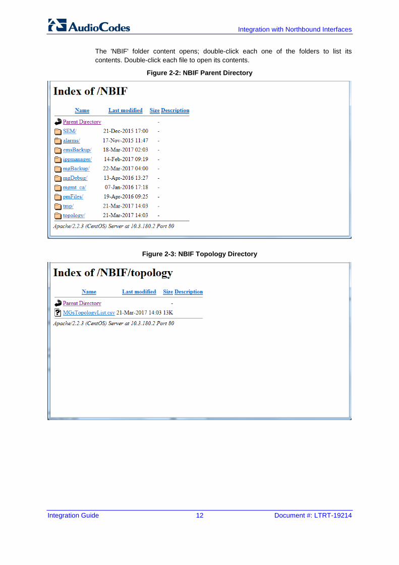
The 'NBIF' folder content opens; double-click each one of the folders to list its contents. Double-click each file to open its contents.
Figure 2-2: NBIF Parent Directory
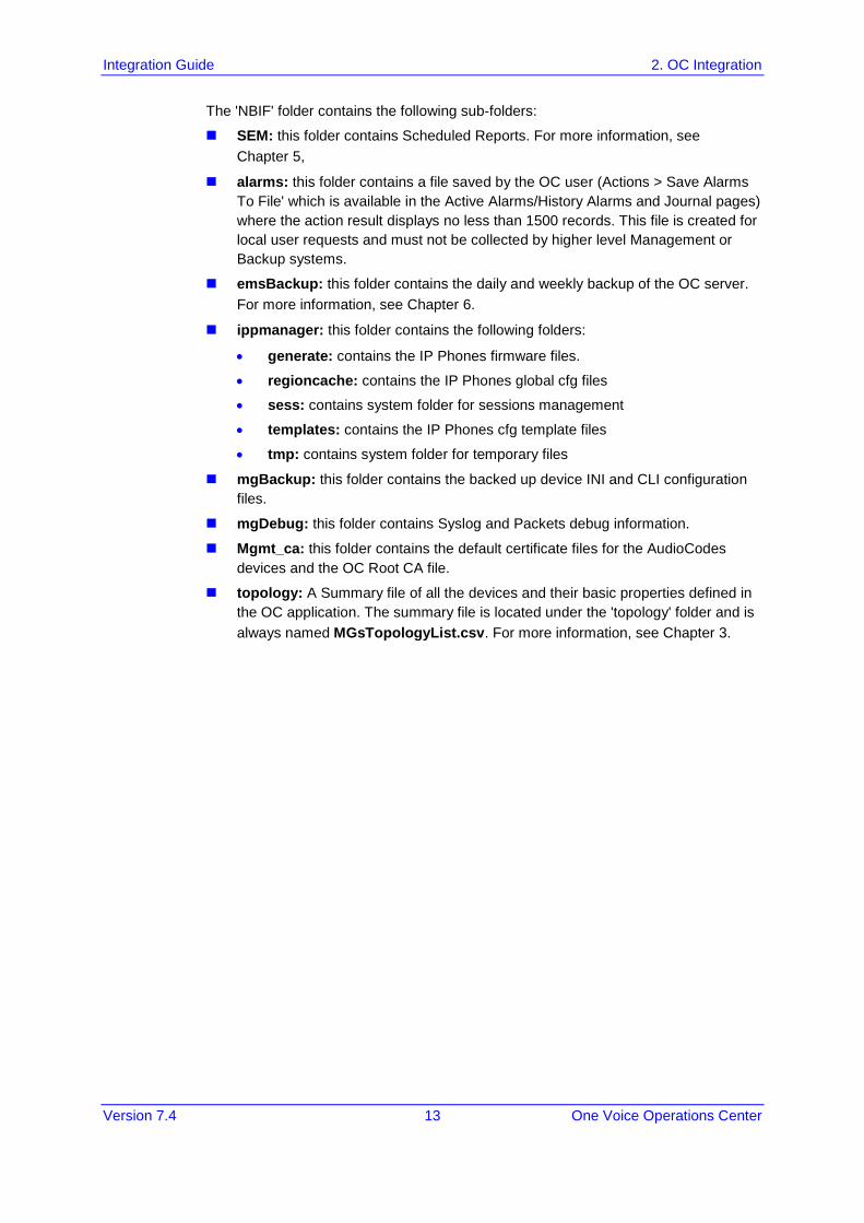
Figure 2-3: NBIF Topology Directory
Integration Guide 2. OC Integration
Version 7.4 13 One Voice Operations Center
The 'NBIF' folder contains the following sub-folders:
SEM: this folder contains Scheduled Reports. For more information, see Chapter 5,
alarms: this folder contains a file saved by the OC user (Actions > Save Alarms To File' which is available in the Active Alarms/History Alarms and Journal pages) where the action result displays no less than 1500 records. This file is created for local user requests and must not be collected by higher level Management or Backup systems.
emsBackup: this folder contains the daily and weekly backup of the OC server. For more information, see Chapter 6.
ippmanager: this folder contains the following folders:
• generate: contains the IP Phones firmware files.
• regioncache: contains the IP Phones global cfg files
• sess: contains system folder for sessions management
• templates: contains the IP Phones cfg template files
• tmp: contains system folder for temporary files
mgBackup: this folder contains the backed up device INI and CLI configuration files.
mgDebug: this folder contains Syslog and Packets debug information.
Mgmt_ca: this folder contains the default certificate files for the AudioCodes devices and the OC Root CA file.
topology: A Summary file of all the devices and their basic properties defined in the OC application. The summary file is located under the 'topology' folder and is always named MGsTopologyList.csv. For more information, see Chapter 3.

Integration with Northbound Interfaces
Integration Guide 14 Document #: LTRT-19214
This page is intentionally left blank.
Integration Guide 3. Topology Files
Version 7.4 15 One Voice Operations Center
3 Topology Files Topology files are created and maintained by the OC application. These file includes updated information on the OC topology. The following files are generated by the OC server:
MGsTopologyList.csv (see below)
Topology.xml file (see Section 3.2)
Both the 'MGsTopologyList.csv' and the Topology.xml file can be retrieved using one of the following methods:
Using the ‘Collect Logs’ option in the EMS Server Manager
By FTP or SFTP protocol
Via Telnet or SSH using 'nbif' user via Error! Hyperlink reference not valid. with user nbif, pass_1234
The Topology.xml must be generated manually using the Topology Export procedure (described below in Section 3.2).
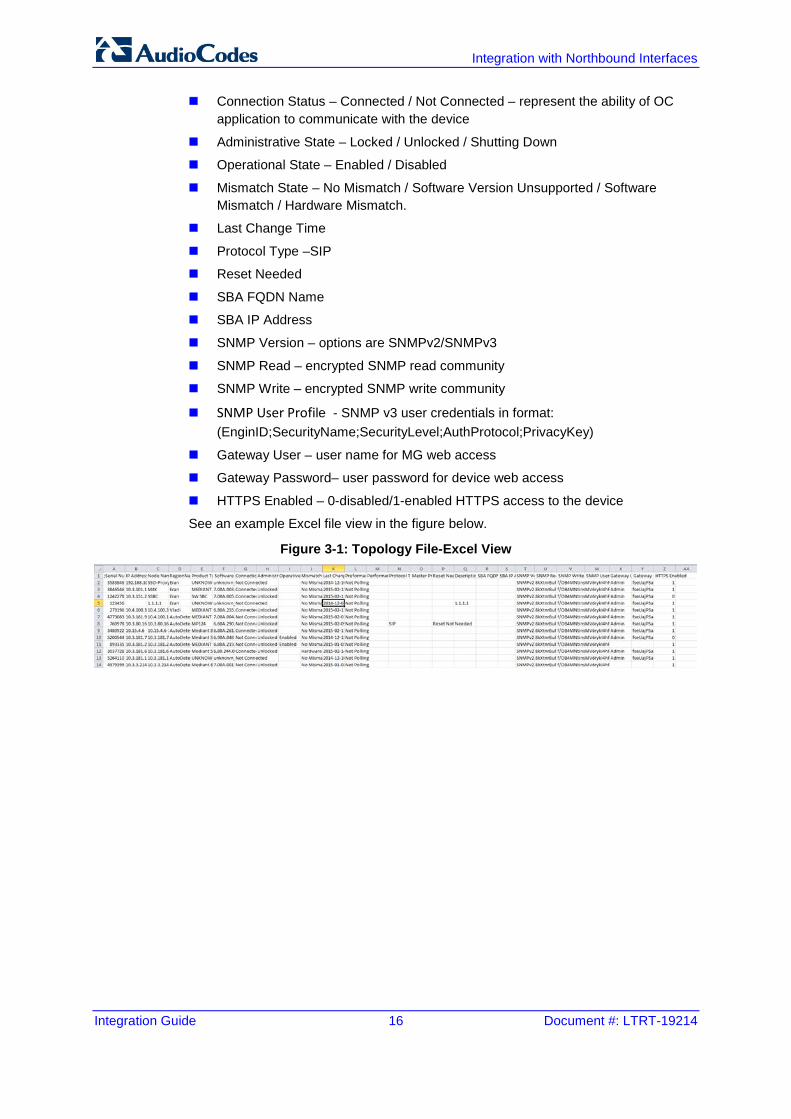
3.1 MGs Topology List The MGsTopologyList.csv file is used by the NMS system to synchronize the list of devices that are currently managed by the OC for the purposes of Alarms Forwarding integration. For example, if a specific device has not been receiving alarms, you can verify in the topology file, whether the relevant device is displayed in the list of connected gateways. The Topology file is automatically updated upon the addition /removal of a device or upon updates to the device's properties, such as name, IP address or region modification. The OC sends 'acEMSTopologyUpdateEvent' (Topology Update) for changes in the definition or update of a device and sends 'acEMSTopologyFileEvent (Topology File Generated) for a topology file update. These events are displayed in the OC Alarm Browser and in the NMS Alarm Browser when the 'OC Events Forwarding' check box is selected in the Trap Configuration 'Destination Rule Configuration' dialog. When multiple devices are added, the Topology file is updated approximately once per minute as the entire operation may take more than a few minutes. For detailed information on the exact event fields, refer to the OVOC Alarms Guide. The file header is composed of two lines commencing with “;” file format version, and column names. Each row in the file represents a device in the OC tree and includes the following information:
Serial Number
IP Address
Node Name
Region Name
Description
Product Type
Software Version
Integration with Northbound Interfaces
Integration Guide 16 Document #: LTRT-19214
Connection Status – Connected / Not Connected – represent the ability of OC application to communicate with the device
Administrative State – Locked / Unlocked / Shutting Down
Operational State – Enabled / Disabled
Mismatch State – No Mismatch / Software Version Unsupported / Software Mismatch / Hardware Mismatch.
Last Change Time
Protocol Type –SIP
Reset Needed
SBA FQDN Name
SBA IP Address
SNMP Version – options are SNMPv2/SNMPv3
SNMP Read – encrypted SNMP read community
SNMP Write – encrypted SNMP write community
SNMP User Profile - SNMP v3 user credentials in format: (EnginID;SecurityName;SecurityLevel;AuthProtocol;PrivacyKey)
Gateway User – user name for MG web access
Gateway Password– user password for device web access
HTTPS Enabled – 0-disabled/1-enabled HTTPS access to the device
See an example Excel file view in the figure below.
Figure 3-1: Topology File-Excel View
Integration Guide 3. Topology Files
Version 7.4 17 One Voice Operations Center
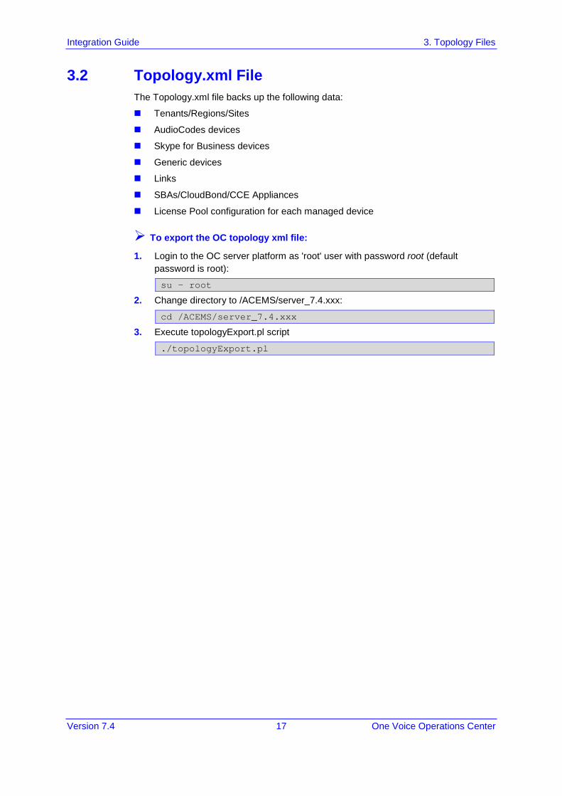
3.2 Topology.xml File The Topology.xml file backs up the following data:
Tenants/Regions/Sites
AudioCodes devices
Skype for Business devices
Generic devices
Links
SBAs/CloudBond/CCE Appliances
License Pool configuration for each managed device
To export the OC topology xml file:
1. Login to the OC server platform as 'root' user with password root (default password is root):
su – root
2. Change directory to /ACEMS/server_7.4.xxx:
cd /ACEMS/server_7.4.xxx
3. Execute topologyExport.pl script
./topologyExport.pl

Integration with Northbound Interfaces
Integration Guide 18 Document #: LTRT-19214
This page is intentionally left blank.
Integration Guide 4. Fault Management
Version 7.4 19 One Voice Operations Center
4 Fault Management AudioCodes devices and IP Phones report their faults (alarms and events) and state changes (Administrative/Operative state) via SNMP notification traps. Both standard and proprietary traps are supported. AudioCodes proprietary traps have the same variable bindings set. Each alarm includes information required by the ITU-T X.733 standard. Operative and Administrative states are managed according to the ITU-T X.731 standard. See the OC Alarms Guide for the exact list of standard, MG proprietary and OC proprietary traps that are supported for each device. For each trap description, it’s indicated whether the trap is defined as an alarm or an event.
4.1 Alarms and Events Forwarding to the NMS Alarms can be forwarded to the NMS using one of the following methods:
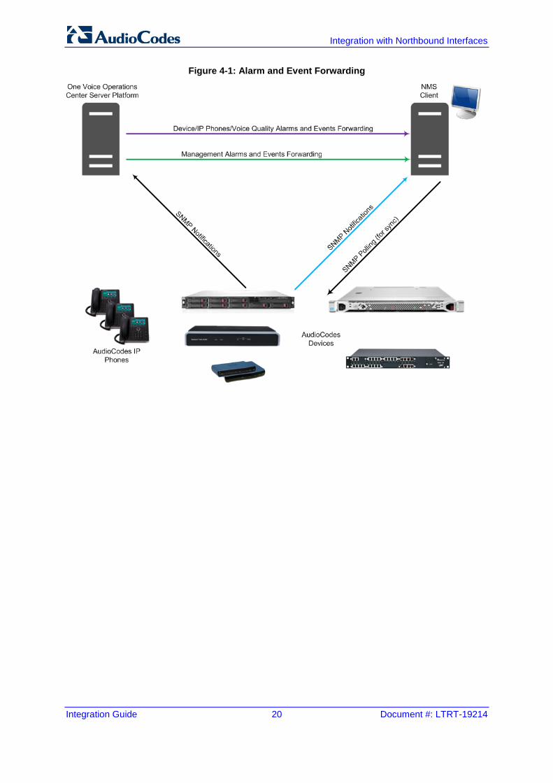
Alarms and events are forwarded by the OC application to the NMS for all network elements (devices, IP Phones and Voice Management) (purple-colored path in the figure below) or only Management alarms and events are forwarded (green-colored path in the figure below).
Each one of the network elements (devices and IP Phones) sends its own alarms directly to the NMS (blue-colored path in the figure below). The device can send alarms to several destinations (the exact number of destinations depends on the device type). For example, the device can send alarms to the OC and NMS. You can configure each destination with a different trap port.
Traps are forwarded to the NMS as SNMPv2 or SNMPv3 Notifications. The SNMPv3 protocol provides more sophisticated security mechanisms than SNMPv2c. It implements a user-based security model (USM), allowing both authentication and encryption of the requests sent between the OC Manager and their agents, as well as user-based access control. SNMP can be configured in the OC at the global level using an SNMP Connectivity template, at the tenant level (Tenant SNMP Profile). You must configure identical SNMP settings on all managed devices.
Note: Although the OC can forward alarms and events in several formats (SNMP Notifications, Mail and Syslog), alarms and events are always sent to an NMS as SNMP notifications for purposes of NMS integration (see Section 4.1).
Integration with Northbound Interfaces
Integration Guide 20 Document #: LTRT-19214
Figure 4-1: Alarm and Event Forwarding
Integration Guide 4. Fault Management
Version 7.4 21 One Voice Operations Center
4.1.1 Forwarding Alarms from OC Server to the NMS This section describes how to configure alarms forwarding from the OC server to the NMS.
To forward alarms from the OC to the NMS:
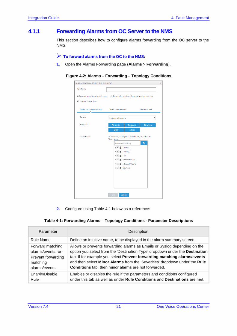
1. Open the Alarms Forwarding page (Alarms > Forwarding).
Figure 4-2: Alarms – Forwarding – Topology Conditions
2. Configure using Table 4-1 below as a reference:
Table 4-1: Forwarding Alarms – Topology Conditions - Parameter Descriptions
Parameter Description
Rule Name Define an intuitive name, to be displayed in the alarm summary screen. Forward matching alarms/events -or- Prevent forwarding matching alarms/events
Allows or prevents forwarding alarms as Emails or Syslog depending on the option you select from the 'Destination Type' dropdown under the Destination tab. If for example you select Prevent forwarding matching alarms/events and then select Minor Alarms from the 'Severities' dropdown under the Rule Conditions tab, then minor alarms are not forwarded.
Enable/Disable Rule
Enables or disables the rule if the parameters and conditions configured under this tab as well as under Rule Conditions and Destinations are met.
Integration with Northbound Interfaces
Integration Guide 22 Document #: LTRT-19214
Parameter Description
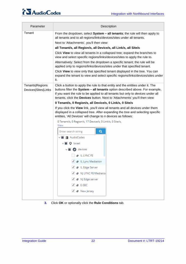
Tenant From the dropdown, select System – all tenants; the rule will then apply to all tenants and to all regions/links/devices/sites under all tenants. Next to 'Attachments', you'll then view: all Tenant/s, all Region/s, all Device/s, all Link/s, all Site/s Click View to view all tenants in a collapsed tree; expand the branches to view and select specific regions/links/devices/sites to apply the rule to. Alternatively: Select from the dropdown a specific tenant; the rule will be applied only to regions/links/devices/sites under that specified tenant. Click View to view only that specified tenant displayed in the tree. You can expand the tenant to view and select specific regions/links/devices/sites under it.
Tenants|Regions Devices|Sites|Links
Click a button to apply the rule to that entity and the entities under it. The buttons filter the System – all tenants option described above. For example, if you want the rule to be applied to all tenants but only to devices under all tenants, click the Devices button. Next to 'Attachments' you'll then view: 0 Tenant/s, 0 Region/s, all Device/s, 0 Link/s, 0 Site/s If you click the View link, you'll view all tenants and all devices under them displayed in a collapsed tree. After expanding the tree and selecting specific entities, 'All Devices' will change to n devices as follows:
3. Click OK or optionally click the Rule Conditions tab.
Integration Guide 4. Fault Management
Version 7.4 23 One Voice Operations Center
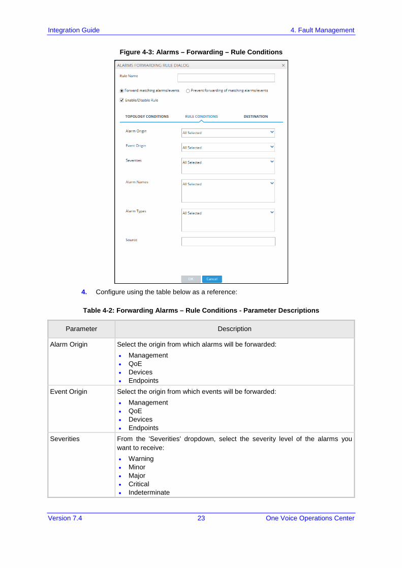
Figure 4-3: Alarms – Forwarding – Rule Conditions
4. Configure using the table below as a reference:
Table 4-2: Forwarding Alarms – Rule Conditions - Parameter Descriptions
Parameter Description
Alarm Origin Select the origin from which alarms will be forwarded: • Management • QoE • Devices • Endpoints
Event Origin Select the origin from which events will be forwarded: • Management • QoE • Devices • Endpoints
Severities From the 'Severities' dropdown, select the severity level of the alarms you want to receive: • Warning • Minor • Major • Critical • Indeterminate
Integration with Northbound Interfaces
Integration Guide 24 Document #: LTRT-19214
Parameter Description
Default: All Selected.
Alarm Names Allows forwarding alarms according to specific alarm names. For example, if you select Power Supply Failure then only this alarm will be forwarded. Default: All Selected.
Alarm Types Allows forwarding alarms according to specific alarm types. For example, if you select communicationsAlarm then only this alarm type will be forwarded. Default: All Selected.
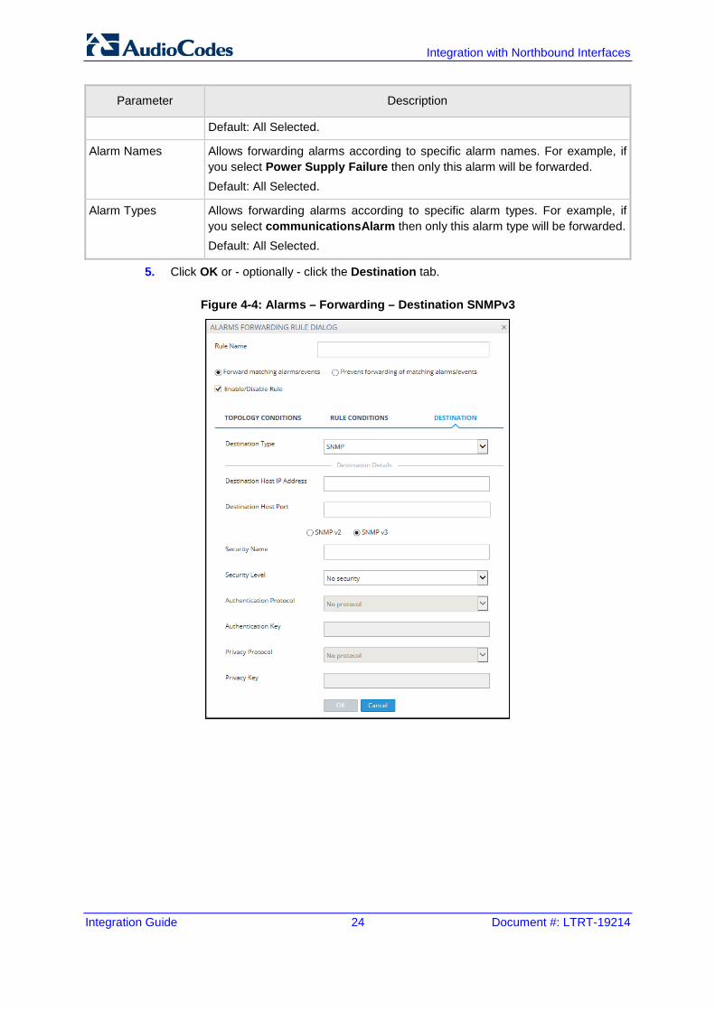
5. Click OK or - optionally - click the Destination tab.
Figure 4-4: Alarms – Forwarding – Destination SNMPv3
Integration Guide 4. Fault Management
Version 7.4 25 One Voice Operations Center
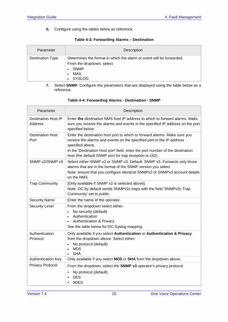
6. Configure using the tables below as reference:
Table 4-3: Forwarding Alarms – Destination
Parameter Description
Destination Type Determines the format in which the alarm or event will be forwarded. From the dropdown, select • SNMP • MAIL • SYSLOG
7. Select SNMP. Configure the parameters that are displayed using the table below as a reference.
Table 4-4: Forwarding Alarms - Destination - SNMP
Parameter Description
Destination Host IP Address
Enter the destination NMS host IP address to which to forward alarms. Make sure you receive the alarms and events in the specified IP address on the port specified below.
Destination Host Port
Enter the destination host port to which to forward alarms. Make sure you receive the alarms and events on the specified port in the IP address specified above. In the 'Destination Host port' field, enter the port number of the destination host (the default SNMP port for trap reception is 162).
SNMP v2/SNMP v3 Select either SNMP v2 or SNMP v3. Default: SNMP v3. Forwards only those alarms that are in the format of the SNMP version you select. Note: ensure that you configure identical SNMPv2 or SNMPv3 account details on the NMS.
Trap Community [Only available if SNMP v2 is selected above]. Note: OC by default sends SNMPv2c traps with the field 'SNMPv2c Trap Community' set to public.
Security Name Enter the name of the operator. Security Level From the dropdown select either:
• No security (default) • Authentication • Authentication & Privacy See the table below for OC-Syslog mapping.
Authentication Protocol
Only available if you select Authentication or Authentication & Privacy from the dropdown above. Select either: • No protocol (default) • MD5 • SHA
Authentication Key Only available if you select MD5 or SHA from the dropdown above. Privacy Protocol From the dropdown, select the SNMP v3 operator's privacy protocol.
No protocol (default) DES 3DES
Integration with Northbound Interfaces
Integration Guide 26 Document #: LTRT-19214
Parameter Description
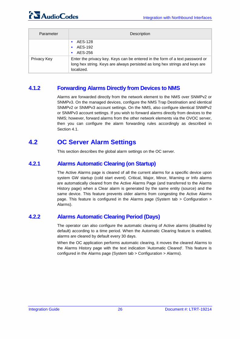
AES-128 AES-192 AES-256
Privacy Key Enter the privacy key. Keys can be entered in the form of a text password or long hex string. Keys are always persisted as long hex strings and keys are localized.
4.1.2 Forwarding Alarms Directly from Devices to NMS Alarms are forwarded directly from the network element to the NMS over SNMPv2 or SNMPv3. On the managed devices, configure the NMS Trap Destination and identical SNMPv2 or SNMPv3 account settings. On the NMS, also configure identical SNMPv2 or SNMPv3 account settings. If you wish to forward alarms directly from devices to the NMS; however, forward alarms from the other network elements via the OVOC server, then you can configure the alarm forwarding rules accordingly as described in Section 4.1.
4.2 OC Server Alarm Settings This section describes the global alarm settings on the OC server.
4.2.1 Alarms Automatic Clearing (on Startup) The Active Alarms page is cleared of all the current alarms for a specific device upon system GW startup (cold start event). Critical, Major, Minor, Warning or Info alarms are automatically cleared from the Active Alarms Page (and transferred to the Alarms History page) when a Clear alarm is generated by the same entity (source) and the same device. This feature prevents older alarms from congesting the Active Alarms page. This feature is configured in the Alarms page (System tab > Configuration > Alarms).
4.2.2 Alarms Automatic Clearing Period (Days) The operator can also configure the automatic clearing of Active alarms (disabled by default) according to a time period. When the Automatic Clearing feature is enabled, alarms are cleared by default every 30 days. When the OC application performs automatic clearing, it moves the cleared Alarms to the Alarms History page with the text indication 'Automatic Cleared'. This feature is configured in the Alarms page (System tab > Configuration > Alarms).
Integration Guide 4. Fault Management
Version 7.4 27 One Voice Operations Center
4.2.3 Events Clearing Mechanism Events are informative messages for OC and device actions (usually with low severity). Device events (originating from the device) are automatically cleared from the Active Alarms page upon GW startup (cold start event); however, device events originating in the OC (e.g. adding a gateway) are not cleared upon device reset. The OC consequently employs a mechanism to automatically clear these events from the Alarms page (by default this feature is enabled and events are cleared every three days). This feature prevents old events from congesting the Active Alarms page. When automatic clearing is performed, the cleared Events are moved to the Alarm History page with the text indication 'Automatic Cleared'. This feature is configured in the Alarms page (System tab > Configuration > Alarms).
4.2.4 Alarm Suppression Mechanism This option enables the generating of the 'Alarm Suppression' alarm when the OC server identifies that the number of alarms of the same type and from the same source, generated in a time period, is greater than the number defined in the threshold. At this point, these alarms are not added to the database and are not forwarded to configured destinations. This feature is configured in the Alarms page (System tab > Configuration > Alarms).
4.2.5 Alarms Sequence Numbering 1. When receiving alarms directly from the devices and endpoints:
• These alarms and events have a different scala of sequence numbers. These sequence numbers are placed at 'TrapGlobalsUniqID' varbindings (respectively 'tgTrapGlobalsUniqID', 'acBoardTrapGlobalsUniqID').
• OC alarms have a sequence number scala. Events are always sent with 'acEMSTrapGlobalsUniqID -1'.
2. When the OC server forwards device and OC alarms:
• Cold Start Trap is the only standard event that is forwarded by the OC application. All other standard events are not forwarded.
• Each one of the alarms and events are forwarded with the original Notification OID and variable bindings OIDs.
• The original content of 'TrapGlobalsUniqID' varbinding (respectively 'tgTrapGlobalsUniqID', 'acBoardTrapGlobalsUniqID' and 'acEMSTrapGlobalsUniqID') is updated as follows: ♦ For all the forwarded events, the 'TrapGlobalsUniqID' is set to -1. ♦ For all the forwarded alarms, the original 'TrapGlobalsUniqID' is
replaced with the OC sequence number, allowing the NMS to follow the forwarded alarms sequencing. The original device 'TrapGlobalsUniqID' is applied to 'TrapGlobalsAdditionalInfo3' varbinding.
Integration with Northbound Interfaces
Integration Guide 28 Document #: LTRT-19214
♦ For all the forwarded alarms and events, 'TrapGlobalsAdditionalInfo3' varbinding (respectively 'tgTrapGlobals AdditionalInfo3', 'acBoardTrapGlobals AdditionalInfo3' and 'acEMSTrapGlobals' 'AdditionalInfo3') is updated as follows: original device IP address and device 'TrapGlobalsUniqID' in the following format:
GATEWAY_IP:x ,GATEWAY_TRAP_ID:y
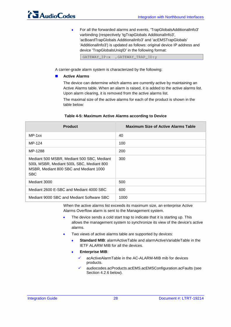
A carrier-grade alarm system is characterized by the following:
Active Alarms The device can determine which alarms are currently active by maintaining an Active Alarms table. When an alarm is raised, it is added to the active alarms list. Upon alarm clearing, it is removed from the active alarms list. The maximal size of the active alarms for each of the product is shown in the table below:
Table 4-5: Maximum Active Alarms according to Device
Product Maximum Size of Active Alarms Table
MP-1xx 40
MP-124 100
MP-1288 200
Mediant 500 MSBR, Mediant 500 SBC, Mediant 500L MSBR, Mediant 500L SBC, Mediant 800 MSBR, Mediant 800 SBC and Mediant 1000 SBC
300
Mediant 3000 500
Mediant 2600 E-SBC and Mediant 4000 SBC 600
Mediant 9000 SBC and Mediant Software SBC 1000
When the active alarms list exceeds its maximum size, an enterprise Active Alarms Overflow alarm is sent to the Management system.
• The device sends a cold start trap to indicate that it is starting up. This allows the management system to synchronize its view of the device's active alarms.
• Two views of active alarms table are supported by devices: ♦ Standard MIB: alarmActiveTable and alarmActiveVariableTable in the
IETF ALARM MIB for all the devices. ♦ Enterprise MIB: acActiveAlarmTable in the AC-ALARM-MIB mib for devices
products. audiocodes.acProducts.acEMS.acEMSConfiguration.acFaults (see
Section 4.2.6 below).
Integration Guide 4. Fault Management
Version 7.4 29 One Voice Operations Center
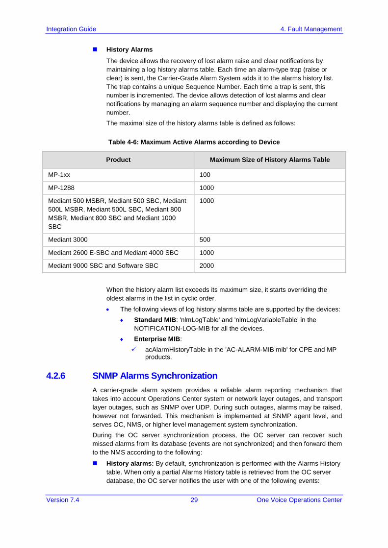
History Alarms
The device allows the recovery of lost alarm raise and clear notifications by maintaining a log history alarms table. Each time an alarm-type trap (raise or clear) is sent, the Carrier-Grade Alarm System adds it to the alarms history list. The trap contains a unique Sequence Number. Each time a trap is sent, this number is incremented. The device allows detection of lost alarms and clear notifications by managing an alarm sequence number and displaying the current number. The maximal size of the history alarms table is defined as follows:
Table 4-6: Maximum Active Alarms according to Device
Product Maximum Size of History Alarms Table
MP-1xx 100
MP-1288 1000
Mediant 500 MSBR, Mediant 500 SBC, Mediant 500L MSBR, Mediant 500L SBC, Mediant 800 MSBR, Mediant 800 SBC and Mediant 1000 SBC
1000
Mediant 3000 500
Mediant 2600 E-SBC and Mediant 4000 SBC 1000
Mediant 9000 SBC and Software SBC 2000
When the history alarm list exceeds its maximum size, it starts overriding the oldest alarms in the list in cyclic order.
• The following views of log history alarms table are supported by the devices: ♦ Standard MIB: 'nlmLogTable' and 'nlmLogVariableTable' in the
NOTIFICATION-LOG-MIB for all the devices. ♦ Enterprise MIB: acAlarmHistoryTable in the 'AC-ALARM-MIB mib' for CPE and MP
products.
4.2.6 SNMP Alarms Synchronization A carrier-grade alarm system provides a reliable alarm reporting mechanism that takes into account Operations Center system or network layer outages, and transport layer outages, such as SNMP over UDP. During such outages, alarms may be raised, however not forwarded. This mechanism is implemented at SNMP agent level, and serves OC, NMS, or higher level management system synchronization. During the OC server synchronization process, the OC server can recover such missed alarms from its database (events are not synchronized) and then forward them to the NMS according to the following:
History alarms: By default, synchronization is performed with the Alarms History table. When only a partial Alarms History table is retrieved from the OC server database, the OC server notifies the user with one of the following events:
Integration with Northbound Interfaces
Integration Guide 30 Document #: LTRT-19214
'Synchronizing Alarms Event' and 'Synchronizing Active Alarms Event'. For more information, see the OC Alarms Guide.
Active alarms: By default, synchronization is not performed with the Active Alarms table; however, a mechanism can be implemented to perform random synchronization of this table (see below).
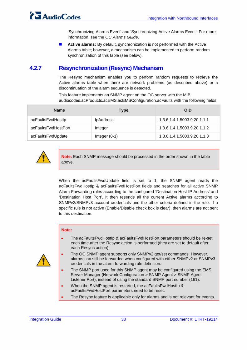
4.2.7 Resynchronization (Resync) Mechanism The Resync mechanism enables you to perform random requests to retrieve the Active alarms table when there are network problems (as described above) or a discontinuation of the alarm sequence is detected. This feature implements an SNMP agent on the OC server with the MIB audiocodes.acProducts.acEMS.acEMSConfiguration.acFaults with the following fields:
Name Type OID
acFaultsFwdHostIp IpAddress 1.3.6.1.4.1.5003.9.20.1.1.1
acFaultsFwdHostPort Integer 1.3.6.1.4.1.5003.9.20.1.1.2
acFaultsFwdUpdate Integer (0-1) 1.3.6.1.4.1.5003.9.20.1.1.3
Note: Each SNMP message should be processed in the order shown in the table above.
When the acFaultsFwdUpdate field is set to 1, the SNMP agent reads the acFaultsFwdHostIp & acFaultsFwdHostPort fields and searches for all active SNMP Alarm Forwarding rules according to the configured ‘Destination Host IP Address’ and ‘Destination Host Port’. It then resends all the current Active alarms according to SNMPv2/SNMPv3 account credentials and the other criteria defined in the rule. If a specific rule is not active (Enable/Disable check box is clear), then alarms are not sent to this destination.
Note:
• The acFaultsFwdHostIp & acFaultsFwdHostPort parameters should be re-set each time after the Resync action is performed (they are set to default after each Resync action).
• The OC SNMP agent supports only SNMPv2 get/set commands. However, alarms can still be forwarded when configured with either SNMPv2 or SNMPv3 credentials in the alarm forwarding rule definition.
• The SNMP port used for this SNMP agent may be configured using the EMS Server Manager (Network Configuration > SNMP Agent > SNMP Agent Listener Port), instead of using the standard SNMP port number (161).
• When the SNMP agent is restarted, the acFaultsFwdHostIp & acFaultsFwdHostPort parameters need to be reset.
• The Resync feature is applicable only for alarms and is not relevant for events.
Integration Guide 4. Fault Management
Version 7.4 31 One Voice Operations Center
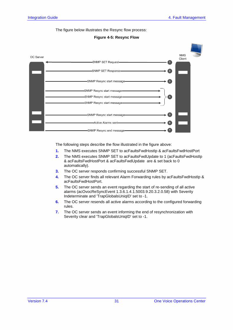
The figure below illustrates the Resync flow process:
Figure 4-5: Resync Flow
The following steps describe the flow illustrated in the figure above: 1. The NMS executes SNMP SET to acFaultsFwdHostIp & acFaultsFwdHostPort 2. The NMS executes SNMP SET to acFaultsFwdUpdate to 1 (acFaultsFwdHostIp
& acFaultsFwdHostPort & acFaultsFwdUpdate are & set back to 0 automatically).
3. The OC server responds confirming successful SNMP SET. 4. The OC server finds all relevant Alarm Forwarding rules by acFaultsFwdHostIp &
acFaultsFwdHostPort. 5. The OC server sends an event regarding the start of re-sending of all active
alarms (acOvocReSyncEvent 1.3.6.1.4.1.5003.9.20.3.2.0.58) with Severity Indeterminate and 'TrapGlobalsUniqID' set to -1.
6. The OC server resends all active alarms according to the configured forwarding rules.
7. The OC server sends an event informing the end of resynchronization with Severity clear and 'TrapGlobalsUniqID' set to -1.
Integration with Northbound Interfaces
Integration Guide 32 Document #: LTRT-19214
Note:
• Alarms are not cleared from the Active alarms table when the OC server is reset.
• When a device is deleted or removed from the OC Web client, its active alarms are also removed from the Active Active alarms table.
• Alarms are forwarded in the sequence order that they were received on the OC server.
• SNMP traps are sent from source port 1164-1165 on the OC server. Voice Quality Management traps are sent from port 1163.
• The Resync operation can be performed on up to three simultaneously active SNMP forwarding rules.
• The Resync operation can send up to 5000 of the last received alarms. • New alarms raised during the Resync operation are also forwarded. • There can be up to two concurrent Resync processes. If more than two
processes are simultaneously active i.e. more than two users are concurrently attempting to perform this operation, then all the additional attempts (greater than two) fail and an error is sent to the log file (see below).
• Resync operation log failures are written to the log ‘alarmsReSync.csv’ (/var/log/ems).
Integration Guide 4. Fault Management
Version 7.4 33 One Voice Operations Center
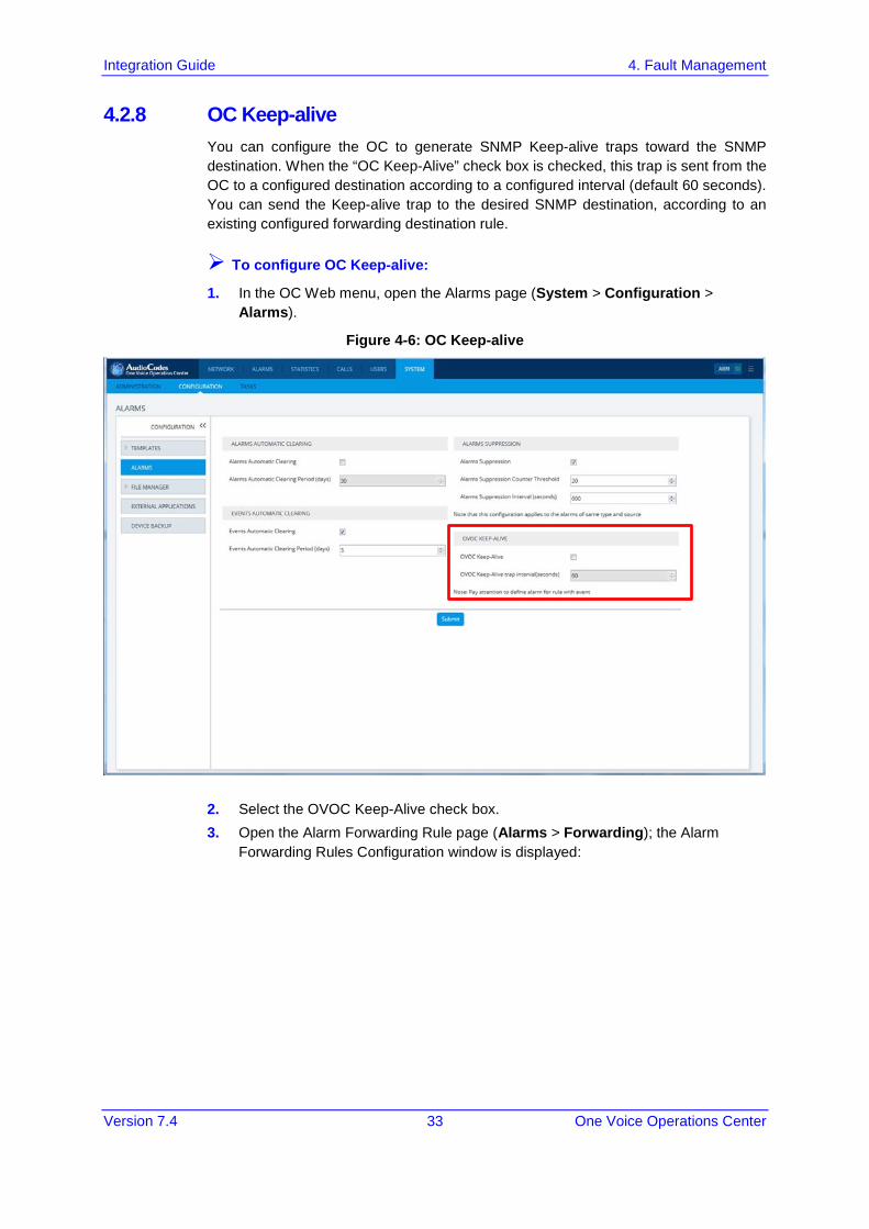
4.2.8 OC Keep-alive You can configure the OC to generate SNMP Keep-alive traps toward the SNMP destination. When the “OC Keep-Alive” check box is checked, this trap is sent from the OC to a configured destination according to a configured interval (default 60 seconds). You can send the Keep-alive trap to the desired SNMP destination, according to an existing configured forwarding destination rule.
To configure OC Keep-alive:
1. In the OC Web menu, open the Alarms page (System > Configuration > Alarms).
Figure 4-6: OC Keep-alive
2. Select the OVOC Keep-Alive check box. 3. Open the Alarm Forwarding Rule page (Alarms > Forwarding); the Alarm
Forwarding Rules Configuration window is displayed:
Integration with Northbound Interfaces
Integration Guide 34 Document #: LTRT-19214
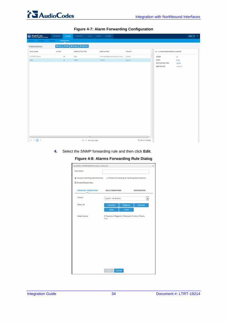
Figure 4-7: Alarm Forwarding Configuration
4. Select the SNMP forwarding rule and then click Edit.
Figure 4-8: Alarms Forwarding Rule Dialog
Integration Guide 4. Fault Management
Version 7.4 35 One Voice Operations Center
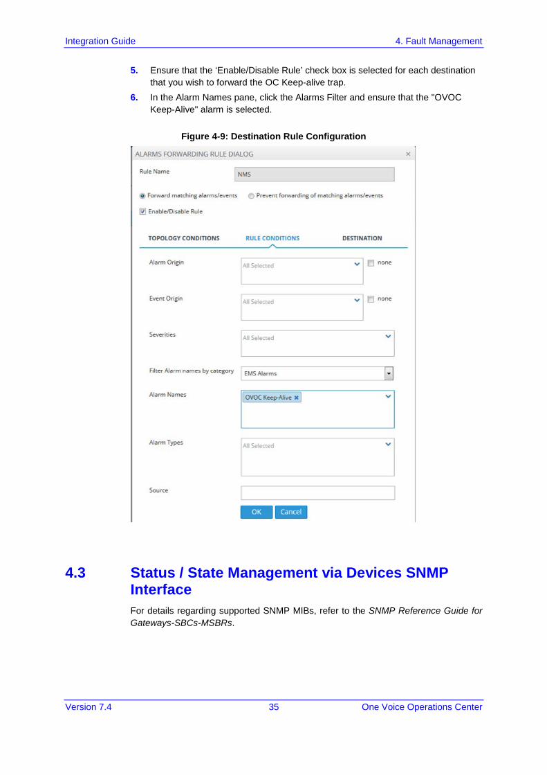
5. Ensure that the ‘Enable/Disable Rule’ check box is selected for each destination that you wish to forward the OC Keep-alive trap.
6. In the Alarm Names pane, click the Alarms Filter and ensure that the "OVOC Keep-Alive" alarm is selected.
Figure 4-9: Destination Rule Configuration
4.3 Status / State Management via Devices SNMP Interface For details regarding supported SNMP MIBs, refer to the SNMP Reference Guide for Gateways-SBCs-MSBRs.

Integration with Northbound Interfaces
Integration Guide 36 Document #: LTRT-19214
This page is intentionally left blank.
Integration Guide 5. Statistics Reports
Version 7.4 37 One Voice Operations Center
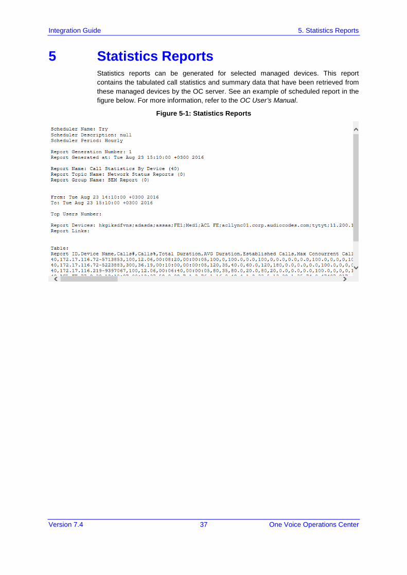
5 Statistics Reports Statistics reports can be generated for selected managed devices. This report contains the tabulated call statistics and summary data that have been retrieved from these managed devices by the OC server. See an example of scheduled report in the figure below. For more information, refer to the OC User’s Manual.
Figure 5-1: Statistics Reports

Integration with Northbound Interfaces
Integration Guide 38 Document #: LTRT-19214
This page is intentionally left blank.
Integration Guide 6. OC Server Backup
Version 7.4 39 One Voice Operations Center
6 OC Server Backup There are two main backup processes that run on the OC server:
Weekly backup: runs once a week at a pre-configured date & time (default is Saturday 02:00). In this process, the whole database is backed up into several “RMAN” files that are located in /NBIF/emsBackup/RmanBackup directory. In addition, many other configuration and software files are backed up to a TAR file in the /data/NBIF/emsBackup directory. In general, this TAR file contains the entire /data/NBIF directory’s content (except 'emsBackup' directory), OC Software Manager content and server_xxx directory’s content.
To change the weekly backup’s time and date, refer to the One Voice Operations Center IOM Manual.
Daily backup: runs daily except on the scheduled week day (see above). The daily backup process backs up the last 24 hours. There are no changes in the TAR file in this process.
Warning: The Backup process does not backup configurations performed using OC Server Manager, such as networking and security.
It is highly recommended to maintain all backup files on an external machine. These files can be transferred outside the server directly from their default location by SCP or SFTP client using 'acems' user. These backup files are as follows:
/data/NBIF/emsBackup/emsServerBackup_<time&date>.tar file.
All files in /data/NBIF/emsBackup/RmanBackup directory (including control.ctl and init.ora files).
Warning: The RmanBackup directory is deleted during an OC server upgrade.

Integration with Northbound Interfaces
Integration Guide 40 Document #: LTRT-19214
This page is intentionally left blank.
Integration Guide 7. Security
Version 7.4 41 One Voice Operations Center
7 Security The following aspects are relevant for the NMS application when integrating the OC and the Media Gateway:
Network Communication Protocols (see below).
OC Users Management (Authentication and Authorization) (see Section 7.2).
HTTPS Connection (see Section 7.3)
Note: For detailed information, refer to the OC Security Guidelines document.
7.1 Network Communication Protocols The following describes the different OC network communication protocols:
OC client - server communication is secured using an HTTPS tunnel with a single HTTPS port. OC also enables client installation and launching via JAWS running over HTTPS.
OC server – managed devices communication can be secured as follows:
• Devices: ♦ SNMPv3 for Maintenance Actions and Faults Management. ♦ HTTPS for file transfer and for Single-Sign On to the device's Web
server
OC server secure access:
• Secure access to the OC server machine is possible via SSH and SFTP protocols for performing maintenance actions and accessing files.
• SNMPv3 traps can be forwarded from the OC server machine to another SNMP Trap Manager.
• OC User Authentication and Authorization is performed either via the OC Application local database, or via a centralized RADIUS or LDAP server database (see Section 7.2) according to the Security profile configured by the OC Administrator. For more information, refer to the 'Security Management' chapter in the OC User's Manual.
Note:
• Syslog messages and emails sent from the OC to a northbound interface are not secured.
• Single sign-on is not supported for devices located behind a NAT.
Integration with Northbound Interfaces
Integration Guide 42 Document #: LTRT-19214
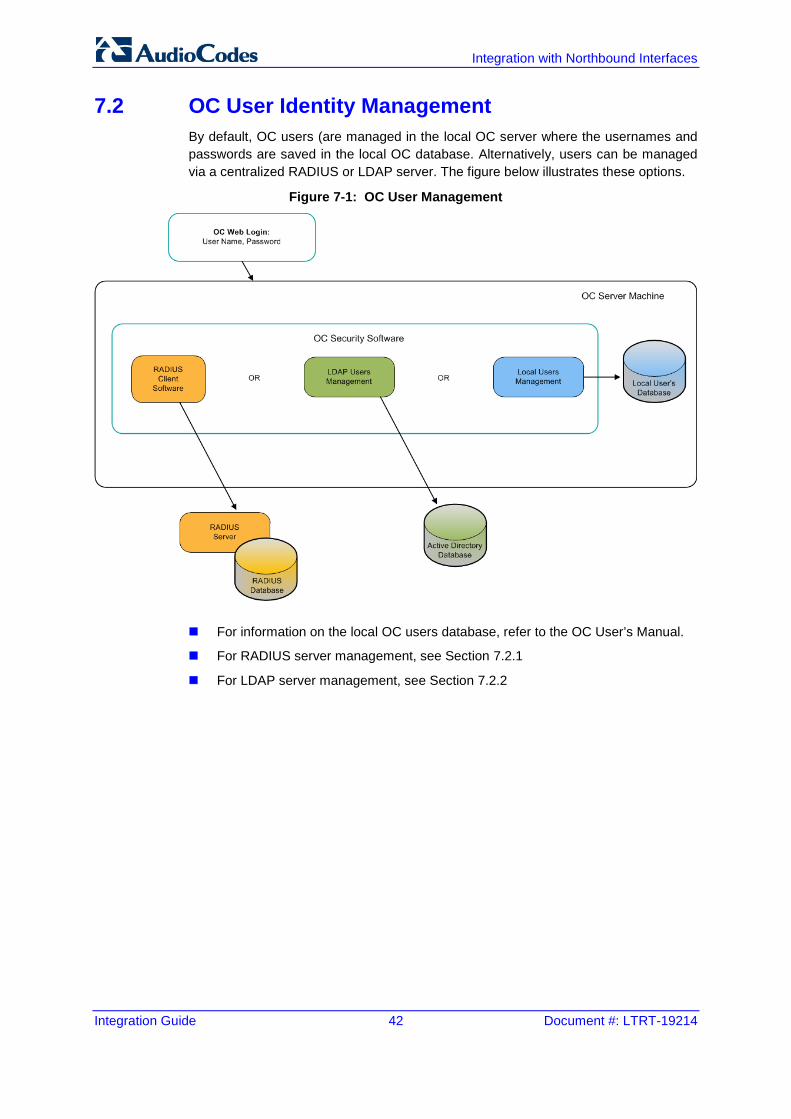
7.2 OC User Identity Management By default, OC users (are managed in the local OC server where the usernames and passwords are saved in the local OC database. Alternatively, users can be managed via a centralized RADIUS or LDAP server. The figure below illustrates these options.
Figure 7-1: OC User Management
For information on the local OC users database, refer to the OC User’s Manual.
For RADIUS server management, see Section 7.2.1
For LDAP server management, see Section 7.2.2
Integration Guide 7. Security
Version 7.4 43 One Voice Operations Center
7.2.1 Authentication and Authorization using a Radius Server Customers may enhance the security and capabilities of logging into the OC application by using a Remote Authentication Dial-In User Service (RADIUS) to store numerous usernames, passwords and access level attributes. This feature allows multiple user management on a centralized platform. RADIUS (RFC 2865) is a standard authentication protocol that defines a method for contacting a pre-defined server and verifying a given name and password pair against a remote database in a secure manner. When accessing the OC application, users must provide a valid username and password of up to 128 Unicode characters. OC doesn’t store the username and password; however, forwards them to the pre-configured RADIUS server for authentication (acceptance or rejection). The local OC users and passwords defined in the Users’ List can be used as a fallback mechanism in case the RADIUS servers do not respond. OC supports the provisioning of up to three Radius servers for redundancy purposes. When the first server does not respond, the OC proceeds to the second server, and then to the third server. OC will always start working with the previously responded server that is indicated as the Current Active Radius servers.
7.2.1.1 Configuring Radius Server Client This section describes an example of a RADIUS server configuration. You must configure the OC server as a RADIUS client to perform authentication and authorization of OC users using the RADIUS server from the OC application. The example configuration is based on FreeRADIUS, which can be downloaded from the following location: www.freeradius.org. Follow the directions on this site for information on installing and configuring the server.
Note: If you use a RADIUS server from a different vendor, refer to the appropriate vendor documentation.
Integration with Northbound Interfaces
Integration Guide 44 Document #: LTRT-19214
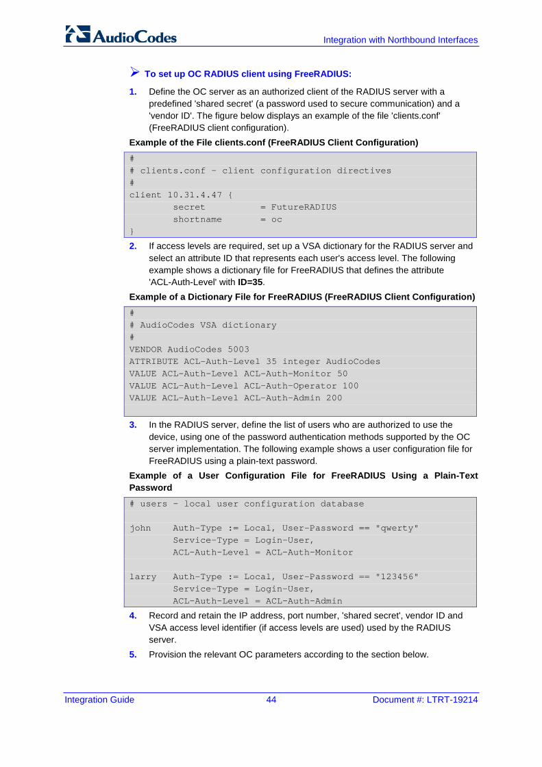
To set up OC RADIUS client using FreeRADIUS:
1. Define the OC server as an authorized client of the RADIUS server with a predefined 'shared secret' (a password used to secure communication) and a 'vendor ID'. The figure below displays an example of the file 'clients.conf' (FreeRADIUS client configuration).
Example of the File clients.conf (FreeRADIUS Client Configuration) # # clients.conf - client configuration directives # client 10.31.4.47 { secret = FutureRADIUS shortname = oc }
2. If access levels are required, set up a VSA dictionary for the RADIUS server and select an attribute ID that represents each user's access level. The following example shows a dictionary file for FreeRADIUS that defines the attribute 'ACL-Auth-Level' with ID=35.
Example of a Dictionary File for FreeRADIUS (FreeRADIUS Client Configuration) # # AudioCodes VSA dictionary # VENDOR AudioCodes 5003 ATTRIBUTE ACL-Auth-Level 35 integer AudioCodes VALUE ACL-Auth-Level ACL-Auth-Monitor 50 VALUE ACL-Auth-Level ACL-Auth-Operator 100 VALUE ACL-Auth-Level ACL-Auth-Admin 200
3. In the RADIUS server, define the list of users who are authorized to use the device, using one of the password authentication methods supported by the OC server implementation. The following example shows a user configuration file for FreeRADIUS using a plain-text password.
Example of a User Configuration File for FreeRADIUS Using a Plain-Text Password # users - local user configuration database john Auth-Type := Local, User-Password == "qwerty" Service-Type = Login-User, ACL-Auth-Level = ACL-Auth-Monitor larry Auth-Type := Local, User-Password == "123456" Service-Type = Login-User, ACL-Auth-Level = ACL-Auth-Admin
4. Record and retain the IP address, port number, 'shared secret', vendor ID and VSA access level identifier (if access levels are used) used by the RADIUS server.
5. Provision the relevant OC parameters according to the section below.
Integration Guide 7. Security
Version 7.4 45 One Voice Operations Center
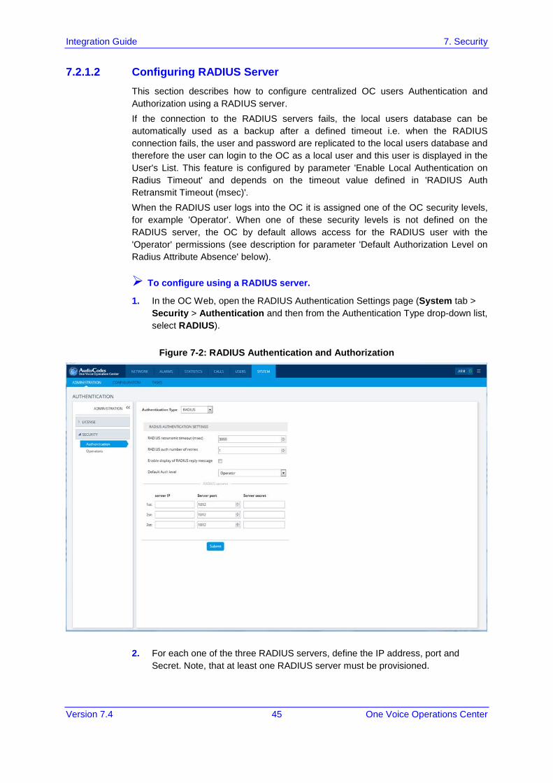
7.2.1.2 Configuring RADIUS Server This section describes how to configure centralized OC users Authentication and Authorization using a RADIUS server. If the connection to the RADIUS servers fails, the local users database can be automatically used as a backup after a defined timeout i.e. when the RADIUS connection fails, the user and password are replicated to the local users database and therefore the user can login to the OC as a local user and this user is displayed in the User's List. This feature is configured by parameter 'Enable Local Authentication on Radius Timeout' and depends on the timeout value defined in 'RADIUS Auth Retransmit Timeout (msec)'. When the RADIUS user logs into the OC it is assigned one of the OC security levels, for example 'Operator'. When one of these security levels is not defined on the RADIUS server, the OC by default allows access for the RADIUS user with the 'Operator' permissions (see description for parameter 'Default Authorization Level on Radius Attribute Absence' below).
To configure using a RADIUS server.
1. In the OC Web, open the RADIUS Authentication Settings page (System tab > Security > Authentication and then from the Authentication Type drop-down list, select RADIUS).
Figure 7-2: RADIUS Authentication and Authorization
2. For each one of the three RADIUS servers, define the IP address, port and Secret. Note, that at least one RADIUS server must be provisioned.
Integration with Northbound Interfaces
Integration Guide 46 Document #: LTRT-19214
3. Define the following parameters:
• RADIUS Auth Retransmit Timeout' (default-3000 msec)
• RADIUS Auth Number of Retries (default-1) Note that these parameters will be used for each one of the Radius Servers.
4. Determine if you wish to display the Radius Reply message. By default, the parameter 'Enable Display of Radius Reply Message' is enabled.
5. Set parameter 'Enable Local Authentication on Radius Timeout' to determine whether local authentication is performed whenever the connection to the RADIUS server fails. By default, the parameter 'Enable Local Authentication on Radius Timeout' i.e. OC local authentication is enabled (see note above). This parameter's behavior depends on the parameter 'RADIUS Auth Retransmit Timeout', whenever this timeout expires, local authentication is performed.
6. Set the parameter 'Default Authorization Level on Radius Attribute Absence' . 'Default Authorization Level on Radius Attribute Absence’. This parameter defines the OC behavior in cases where the user has been successfully authenticated by the RADIUS server; however, the RADIUS server response does not include an OC security level (Authorization Vendor Specific Element). This implies that the user properties custom attribute “Security Level” (this attribute is specifically defined for the OC) has not been defined on the RADIUS server and configured with one of the OC Security levels (Not visible; Monitoring (viewing only); Operation (viewing and all system provisioning operations on devices); Administration or Administrator Super User). In this case, the Administrator can either deny user access or set a default security level to grant to the user. By default, the OC provides access to the application with the “Operator” security level.
7. Configure other parameters as required according to your RADIUS server configuration.
Integration Guide 7. Security
Version 7.4 47 One Voice Operations Center
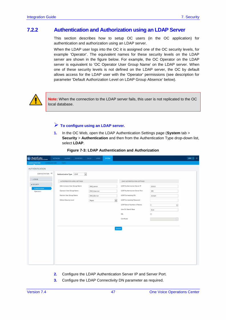
7.2.2 Authentication and Authorization using an LDAP Server This section describes how to setup OC users (in the OC application) for authentication and authorization using an LDAP server. When the LDAP user logs into the OC it is assigned one of the OC security levels, for example 'Operator'. The equivalent names for these security levels on the LDAP server are shown in the figure below. For example, the OC Operator on the LDAP server is equivalent to 'OC Operator User Group Name' on the LDAP server. When one of these security levels is not defined on the LDAP server, the OC by default allows access for the LDAP user with the 'Operator' permissions (see description for parameter 'Default Authorization Level on LDAP Group Absence' below).
Note: When the connection to the LDAP server fails, this user is not replicated to the OC local database.
To configure using an LDAP server.
1. In the OC Web, open the LDAP Authentication Settings page (System tab > Security > Authentication and then from the Authentication Type drop-down list, select LDAP.
Figure 7-3: LDAP Authentication and Authorization
2. Configure the LDAP Authentication Server IP and Server Port. 3. Configure the LDAP Connectivity DN parameter as required.
Integration with Northbound Interfaces
Integration Guide 48 Document #: LTRT-19214
4. Configure LDAP Connectivity Password as required. 5. Configure the User DN Search Base as required. 6. 'Default Authorization Level on LDAP Group Absence’. This parameter defines
the OC behavior in cases where the user has been successfully authenticated by the LDAP server; however, the LDAP server response does not include an OC security level (Authorization Vendor Specific Element). This implies that the user properties custom attribute “Security Level” (this attribute is specifically defined for the OC) has not been defined on the LDAP server and configured with one of the OC Security levels (Not visible; Monitoring (viewing only); Operation (viewing and all system provisioning operations on devices); Administration or Administrator Super User). In this case, the Administrator can either deny user access or set a default security level to grant to the user. By default, the OC provides access to the application with the “Operator” security level.
7. If you wish to secure the connection with the LDAP server over SSL: a. From the "LDAP Server Number of Retries" drop-down list, select one of the
following options: ♦ Plain Connection (default): non-secured connection with the LDAP
server. ♦ SSL With Certificate: an HTTPS connection between the OC server
and the LDAP server is opened. The OC authenticates the SSL connection using a certificate.
♦ SSL Without Certificate: an HTTPS connection between the OC server and the LDAP server is opened; however is not authenticated using a certificate.
b. From the "LDAP Client Certificate" drop-down list, select the certificate file that you wish to use to secure the connection with the LDAP server.
Note:
• If you chose the option “SSL With Certificate”, ensure that you have loaded the required SSL certificate file (certificate required by the LDAP Active Directory platform) to the OC Software Manager using the "Certificate File" option (refer to OC User’s Manual).
• If the login credentials to the LDAP server are incorrect, you will not be able to connect to the LDAP server and an appropriate message is displayed.
7.3 HTTPS Connection The connection between the NBIF client and the OC server is by default secured over HTTPS (port 443). This security is managed by the EMS Server Manager option ‘IP Phone Manager Pro and NBIF Web pages Secured Communication’. You can secure this connection either using AudioCodes default self-signed certificates or by applying custom certificates signed by an external CA. For more information, refer to the OC Security Guidelines document.

Integration Guide 7. Security
Version 7.4 49 One Voice Operations Center
This page is intentionally left blank.

International Headquarters 1 Hayarden Street, Airport City Lod 7019900, Israel Tel: +972-3-976-4000 Fax: +972-3-976-4040 AudioCodes Inc. 27 World’s Fair Drive, Somerset, NJ 08873 Tel: +1-732-469-0880 Fax: +1-732-469-2298 Contact us: www.audiocodes.com/contact Website: www.audiocodes.com
©2017 AudioCodes Ltd. All rights reserved. AudioCodes, AC, HD VoIP, HD VoIP Sounds Better, IPmedia, Mediant, MediaPack, What’s Inside Matters, OSN, SmartTAP, User Management Pack, VMAS, VoIPerfect, VoIPerfectHD, Your Gateway To VoIP, 3GX, VocaNom, AudioCodes One Voice and CloudBond are trademarks or registered trademarks of AudioCodes Limited. All other products or trademarks are property of their respective owners. Product specifications are subject to change without notice.
Document #: LTRT-19214
Related Documents