INTERNATIONAL JOURNAL ON SMART SENSING AND INTELLIGENT SYSTEMS, VOL. 5, NO. 4, DECEMBER 2012 957 ON-BOARD LANE DETECTION SYSTEM FOR INTELLIGENT VEHICLE BASED ON MONOCULAR VISION Xiaodong Miao, Shunming Li, Huan Shen College of Energy and Power Nanjing University of Aeronautics and Astronautics Nanjing, China, 210016 Email: [email protected] Submitted: Aug.15, 2012 Accepted: Sep.22, 2012 Published: Dec.1, 2012 Abstract- The objective of this research is to develop a monocular vision system that can locate the positions of the road lane in real time. First, Canny approach is used to obtain edge map from the road image acquired from monocular camera mount on vehicle; Second, a matching process is conducted to normalize the candidates of road line; Third, a searching method is used for reinforce potential road lines while degraded those impossible ones; Forth, a linking condition is used to further enhance the confidence of the potential lane lines, and a K-means cluster algorithm is employed to localize the lane lines; Finally, a on board system is designed for experiment. The proposed system is shown to work well under various conditions on the roadway. Besides, the computation cost is inexpensive and the system's response is almost real time. Index terms: Intelligent transportation system, machine vision, intelligent vehicle, traffic safety, driver assistant system

Welcome message from author
This document is posted to help you gain knowledge. Please leave a comment to let me know what you think about it! Share it to your friends and learn new things together.
Transcript
INTERNATIONAL JOURNAL ON SMART SENSING AND INTELLIGENT SYSTEMS, VOL. 5, NO. 4, DECEMBER 2012
957
ON-BOARD LANE DETECTION SYSTEM FOR INTELLIGENT VEHICLE BASED ON MONOCULAR VISION
Xiaodong Miao, Shunming Li, Huan Shen
College of Energy and Power
Nanjing University of Aeronautics and Astronautics
Nanjing, China, 210016
Email: [email protected]
Submitted: Aug.15, 2012 Accepted: Sep.22, 2012 Published: Dec.1, 2012
Abstract- The objective of this research is to develop a monocular vision system that can locate the
positions of the road lane in real time. First, Canny approach is used to obtain edge map from the road
image acquired from monocular camera mount on vehicle; Second, a matching process is conducted to
normalize the candidates of road line; Third, a searching method is used for reinforce potential road
lines while degraded those impossible ones; Forth, a linking condition is used to further enhance the
confidence of the potential lane lines, and a K-means cluster algorithm is employed to localize the lane
lines; Finally, a on board system is designed for experiment. The proposed system is shown to work well
under various conditions on the roadway. Besides, the computation cost is inexpensive and the system's
response is almost real time.
Index terms: Intelligent transportation system, machine vision, intelligent vehicle, traffic safety, driver
assistant system
Xiaodong Miao, Shunming Li, and Huan Shen, On-board Lane Detection System for Intelligent Vehicle Based on Monocular Vision
958
I. INTRODUCTION
Recently, the traffic problem is more and more serious with the increase of vehicles. Most traffic
accidents were caused by the negligence of the drivers. In order to reduce the number of traffic
accidents and to improve the safety and efficiency of the traffic, the researches and companies on
Intelligent Transportation System (ITS) have been conducted worldwide for many years.
Intelligent vehicle (IV) system is a component of the ITS system, which aims to assist drivers in
perceiving any dangerous situations earlier to avoid the accidents through sensing and
understanding of the environment around itself [1].
Up to now, there have been numerous research results falling into the field of lane recognition. In
[2], the authors generate the bird's-eye view image of the road plane first by using Inverse
Perspective Mapping (IPM) to remove the perspective effect. Next, it extracts the lane markers
based on the road constraints and the lane marker's width. Another research work with different
philosophy can be seen in [3] where a curve road model was proposed. In that work, a
deformable template method is used to optimize a likelihood function based on the proposed
model. However, it cost huge computational resources.
Several different strategies have been reported in the literature to deal with various road types.
Edges, intensities or other lane-marking features are commonly used for lane detection of
structured roads, which have obvious lane markings, clear edges, relatively high intensities and
specific colours and features. For example, the AURORA system [4] used adjustable templates to
track lane markings for structured roads. Kluge [5] used a deformable template model of lane
structure to locate lane boundaries without thresholding the intensity gradient information. The
GOLD system [6] performed lane detection based on a pattern-matching technique that relies on
the presence of lane markings. The LANA system [7] captured the magnitude and orientation
information of edges based on a set of frequency domain features. Wang et al. computed a
potential edge field and a potential orientation field from the image and applied B-Snake or
Catmull-Rom spline to model curved lanes [8, 9]. The TFALDA system [10] utilized the starting
position, direction and grey-level value of a lane boundary as features to recognize the lanes. The
VioLET system [11] utilized steerable filters for lane-marking detection and used an adaptive
template to estimate road curvature.
INTERNATIONAL JOURNAL ON SMART SENSING AND INTELLIGENT SYSTEMS, VOL. 5, NO. 4, DECEMBER 2012
959
For unstructured roads that have no obvious lane markings or lane boundaries, color and texture
information combined with edges are often employed to distinguish the road surface from the
surroundings under the assumption that the color or texture of the road surface is very different
from the surroundings beside the road. The SCARF system [12] used a set of Gaussians to model
the colors of both off-roads and roads that have degraded surfaces and edges with no lane
markings. Rasmussen [13] assumed that the color of road surface is homogeneous and utilized
texture features to deal with rural roads. Gao et al. [14] presented an unstructured road detection
algorithm through feature learning using colours in HSV representation. Huang et al.[15] also
proposed a system based on HSV color space and road features. In addition to pure vision-based
algorithms, Liu et al. [16] fused multi-sensor data acquired by both a camera and a laser range
finder for unstructured road tracking. Dahlkamp et al. [17] also proposed a system with multiple
sensors. The laser sensor is used to scan for flat, drivable surface area near the vehicle, and the
extracted area is used as the training data for the computer vision algorithm.
Pomerleau [18] proposed a Rapidly Adapting Lateral Position Handler (RALPH) system, which
constitutes an adaptive high-speed matching procedure to determine the lane's curvature and its
lateral offset. Though the RALPH approach reduces computation cost for rapid response, it
suffered from low precision and influenced by the insufficient parameters. There is an additional
approach [19] which combines the Hough Transform and the Line-Snake model. It first divides
an image into a few sub-regions along the vertical direction, and then performs the Hough
transform on each sub-region to obtain an initial estimation of the lane boundaries. Afterwards,
the Line-Snake model is exploited to improve the results of lane boundary detection.
There are some shortcomings in traditional methods [20-22], for example, an algorithm that
performs well on structured roads could work poorly on unstructured roads, whereas an algorithm
suitable for handling rural roads might not be suitable for handling highways. More specifically,
edge or intensity-based methods will fail on unstructured roads because of lack of obvious edges
or markings with bright intensities. On the other hand, the assumption for colour or texture-based
methods does not hold for highways because the colour and texture of one lane does not have
much difference from the lane right next to it.
The purpose of this work is to inherit these promising research results and further explore the
potential of this challenge problem. Generally, a robust and effective lane detection approach
should be comprehensive the following aspects,
Xiaodong Miao, Shunming Li, and Huan Shen, On-board Lane Detection System for Intelligent Vehicle Based on Monocular Vision
960
(1) Considering roads including straight, curved, painted, unpainted roads.
(2) Shadows are presence of results from artifacts produced by trees, buildings, bridges, or other
vehicles, etc.
(3) Moderate computational complexity so that a common embedded processor can qualified; and
effectively cost control so that consumer can afford.
The organization of the lecture is as follows. After a general introduction of the research issue of
the intelligent vehicle system, a real time lane detection algorithm based on monocular vision has
been discussed in section II. The system design includes of hardware and software procedure is
developed in section III. In section IV, the real time experimental results and analysis has been
discussed. Finally, the lecture has been concluded in section V.
II. LANE DETECTION
Considering the complexity of the environment of actual lane, road line is often degraded by
some factors, such as shadows, water, pavement cracks, etc, so in the lane detection process, it is
difficult to achieve both high detection efficiency and robustness, so it is necessary to optimize
the algorithm.
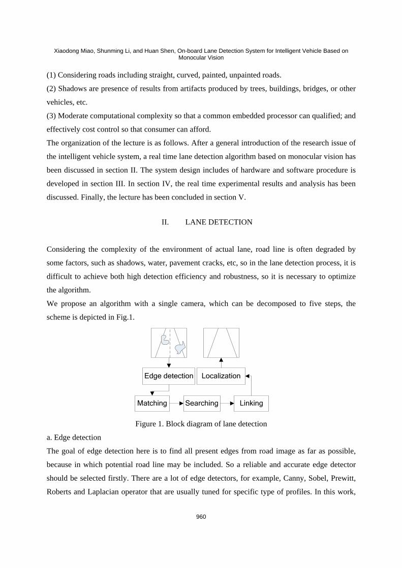
We propose an algorithm with a single camera, which can be decomposed to five steps, the
scheme is depicted in Fig.1.
Edge detection
Searching Linking
Localization
Matching
Figure 1. Block diagram of lane detection
a. Edge detection
The goal of edge detection here is to find all present edges from road image as far as possible,
because in which potential road line may be included. So a reliable and accurate edge detector
should be selected firstly. There are a lot of edge detectors, for example, Canny, Sobel, Prewitt,
Roberts and Laplacian operator that are usually tuned for specific type of profiles. In this work,
INTERNATIONAL JOURNAL ON SMART SENSING AND INTELLIGENT SYSTEMS, VOL. 5, NO. 4, DECEMBER 2012
961
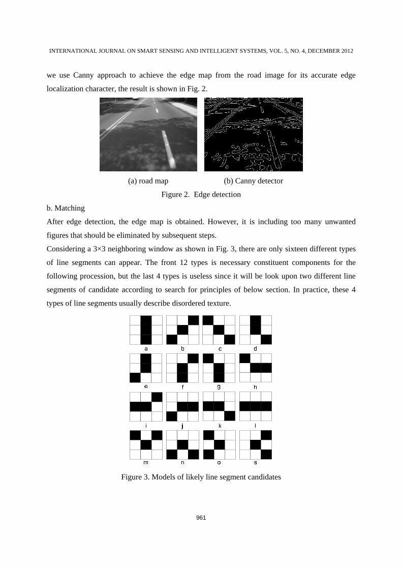
we use Canny approach to achieve the edge map from the road image for its accurate edge
localization character, the result is shown in Fig. 2.
(a) road map (b) Canny detector
Figure 2. Edge detection
b. Matching
After edge detection, the edge map is obtained. However, it is including too many unwanted
figures that should be eliminated by subsequent steps.
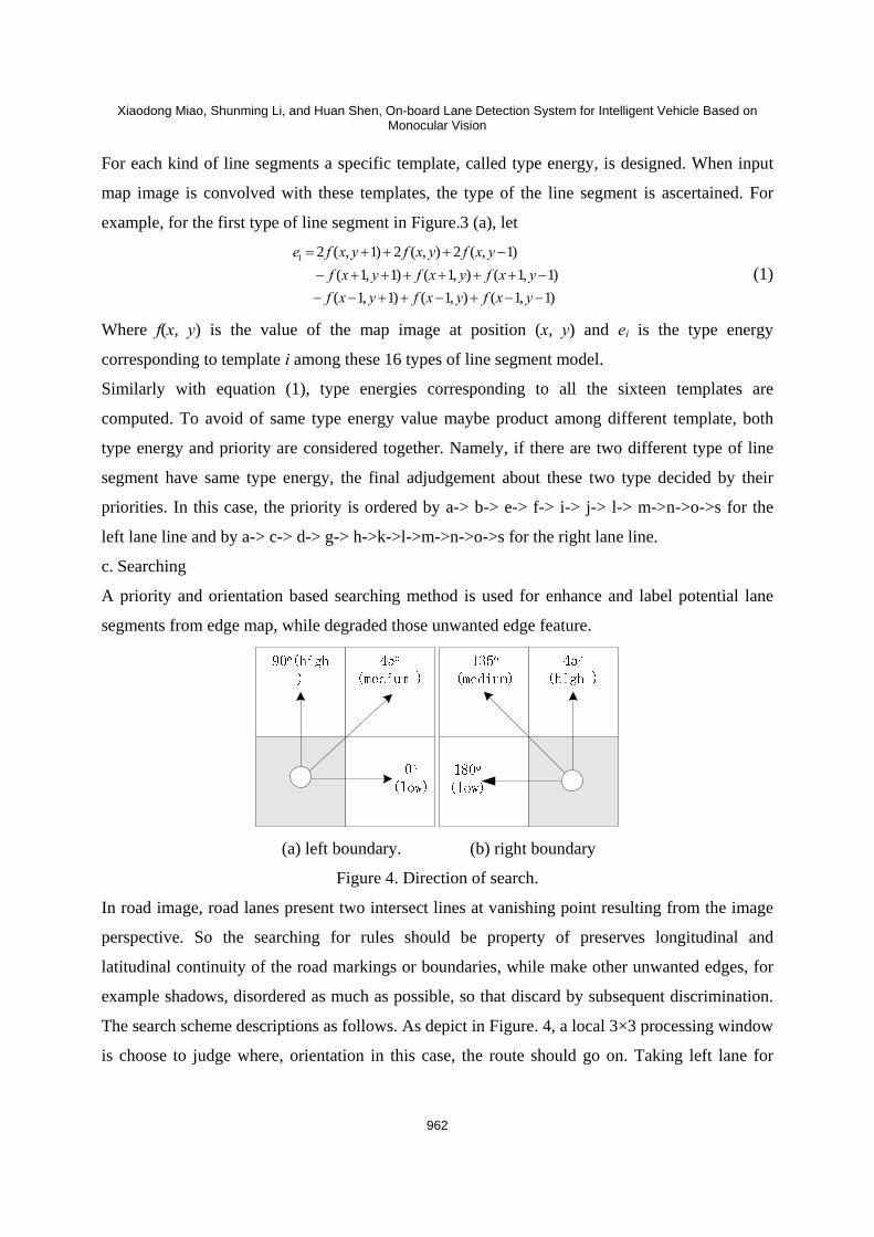
Considering a 3×3 neighboring window as shown in Fig. 3, there are only sixteen different types
of line segments can appear. The front 12 types is necessary constituent components for the
following procession, but the last 4 types is useless since it will be look upon two different line
segments of candidate according to search for principles of below section. In practice, these 4
types of line segments usually describe disordered texture.
Figure 3. Models of likely line segment candidates
Xiaodong Miao, Shunming Li, and Huan Shen, On-board Lane Detection System for Intelligent Vehicle Based on Monocular Vision
962
For each kind of line segments a specific template, called type energy, is designed. When input
map image is convolved with these templates, the type of the line segment is ascertained. For
example, for the first type of line segment in Figure.3 (a), let
1 2 ( , 1) 2 ( , ) 2 ( , 1) ( 1, 1) ( 1, ) ( 1, 1)
( 1, 1) ( 1, ) ( 1, 1)
e f x y f x y f x yf x y f x y f x yf x y f x y f x y
= + + + −− + + + + + + −− − + + − + − −
(1)
Where f(x, y) is the value of the map image at position (x, y) and ei is the type energy
corresponding to template i among these 16 types of line segment model.
Similarly with equation (1), type energies corresponding to all the sixteen templates are
computed. To avoid of same type energy value maybe product among different template, both
type energy and priority are considered together. Namely, if there are two different type of line
segment have same type energy, the final adjudgement about these two type decided by their
priorities. In this case, the priority is ordered by a-> b-> e-> f-> i-> j-> l-> m->n->o->s for the
left lane line and by a-> c-> d-> g-> h->k->l->m->n->o->s for the right lane line.
c. Searching
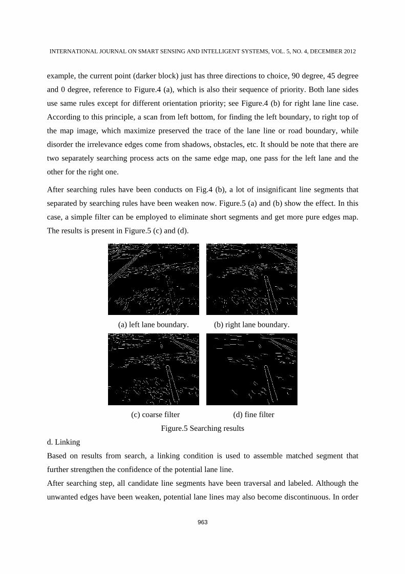
A priority and orientation based searching method is used for enhance and label potential lane
segments from edge map, while degraded those unwanted edge feature.
(a) left boundary. (b) right boundary
Figure 4. Direction of search.
In road image, road lanes present two intersect lines at vanishing point resulting from the image
perspective. So the searching for rules should be property of preserves longitudinal and
latitudinal continuity of the road markings or boundaries, while make other unwanted edges, for
example shadows, disordered as much as possible, so that discard by subsequent discrimination.
The search scheme descriptions as follows. As depict in Figure. 4, a local 3×3 processing window
is choose to judge where, orientation in this case, the route should go on. Taking left lane for
INTERNATIONAL JOURNAL ON SMART SENSING AND INTELLIGENT SYSTEMS, VOL. 5, NO. 4, DECEMBER 2012
963
example, the current point (darker block) just has three directions to choice, 90 degree, 45 degree
and 0 degree, reference to Figure.4 (a), which is also their sequence of priority. Both lane sides
use same rules except for different orientation priority; see Figure.4 (b) for right lane line case.
According to this principle, a scan from left bottom, for finding the left boundary, to right top of
the map image, which maximize preserved the trace of the lane line or road boundary, while
disorder the irrelevance edges come from shadows, obstacles, etc. It should be note that there are
two separately searching process acts on the same edge map, one pass for the left lane and the
other for the right one.
After searching rules have been conducts on Fig.4 (b), a lot of insignificant line segments that
separated by searching rules have been weaken now. Figure.5 (a) and (b) show the effect. In this
case, a simple filter can be employed to eliminate short segments and get more pure edges map.
The results is present in Figure.5 (c) and (d).
(a) left lane boundary. (b) right lane boundary.
(c) coarse filter (d) fine filter
Figure.5 Searching results
d. Linking
Based on results from search, a linking condition is used to assemble matched segment that
further strengthen the confidence of the potential lane line.
After searching step, all candidate line segments have been traversal and labeled. Although the
unwanted edges have been weaken, potential lane lines may also become discontinuous. In order
Xiaodong Miao, Shunming Li, and Huan Shen, On-board Lane Detection System for Intelligent Vehicle Based on Monocular Vision
964
to link those coherence lines into a most prominent line chain, a linking step is considering for
solving this problem.
In mathematics, suppose P (xi, yi) to be a point in edge map and θi is its orientation that can
approximated calculated by equation (2)
1 1
1 1
arg tan( )i ii
i i
y yx x
θ + −
+ −
−=
− (2)
In an edges map, the set of road candidate S is defined as a collection of couple of points
described as follows
{ | ( ( , ), ( , ))} 1,2,k ks ks ke keS s P x y P x y k= = L (3)
Where k is the total number of the edge segments in set S, the P (xks, yks) and P (xke, yke) is the
start and last end point of the kth edge.
( 1) ( 1)
( 1) ( 1)
min ( , ) ( ( , ), ( , )) ( ( , ), ( , ))
0 ( ( , ), ( , ))
0 ( ( , ), ( , ))
ke ke ke ke
ke ke k s k s
ke ke k s k s
ke ke ke ke
L d d P x y P x yP x y P x y
subject to P x y P x y
d P x y P x y
θθ
θ λ
γ
+ +
+ +
= ∠
+
≤ ≤
≤ ∠ ≤
(4)
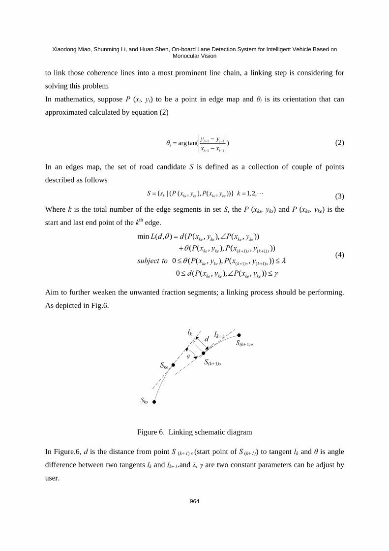
Aim to further weaken the unwanted fraction segments; a linking process should be performing.
As depicted in Fig.6.
Ske
Sks
S(k+1)s
S(k+1)ed
θ
lk lk+1
Figure 6. Linking schematic diagram
In Figure.6, d is the distance from point S (k+1) s (start point of S (k+1)) to tangent lk and θ is angle
difference between two tangents lk and lk+1.and λ, γ are two constant parameters can be adjust by
user.
INTERNATIONAL JOURNAL ON SMART SENSING AND INTELLIGENT SYSTEMS, VOL. 5, NO. 4, DECEMBER 2012
965
e. Localization
Finally, a conventional cluster algorithm is used to localization the lane lines. In this case, K-
means cluster algorithm is chosen.
K-means clustering is a method of cluster analysis which aims to partition n observation in to k
clusters in which each observation belongs to the cluster with the nearest mean. In this paper,
given a set of points(x1,x2,…,xn),the k is decided by the priori knowledge.
After large sample statistics on the computation platform, the platform will be introduced in part
4, we get the compute time of every frame, as shown in table 1. Average processing time of each
frame is 75.6 ms, which means 13 fps, can satisfy the requirements by normal speed.
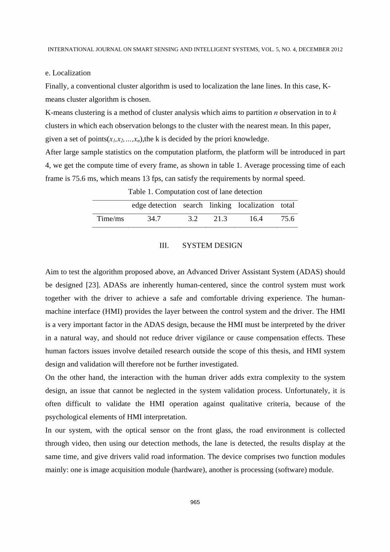
Table 1. Computation cost of lane detection
edge detection search linking localization total
Time/ms 34.7 3.2 21.3 16.4 75.6
III. SYSTEM DESIGN
Aim to test the algorithm proposed above, an Advanced Driver Assistant System (ADAS) should
be designed [23]. ADASs are inherently human-centered, since the control system must work
together with the driver to achieve a safe and comfortable driving experience. The human-
machine interface (HMI) provides the layer between the control system and the driver. The HMI
is a very important factor in the ADAS design, because the HMI must be interpreted by the driver
in a natural way, and should not reduce driver vigilance or cause compensation effects. These
human factors issues involve detailed research outside the scope of this thesis, and HMI system
design and validation will therefore not be further investigated.
On the other hand, the interaction with the human driver adds extra complexity to the system
design, an issue that cannot be neglected in the system validation process. Unfortunately, it is
often difficult to validate the HMI operation against qualitative criteria, because of the
psychological elements of HMI interpretation.
In our system, with the optical sensor on the front glass, the road environment is collected
through video, then using our detection methods, the lane is detected, the results display at the
same time, and give drivers valid road information. The device comprises two function modules
mainly: one is image acquisition module (hardware), another is processing (software) module.
Xiaodong Miao, Shunming Li, and Huan Shen, On-board Lane Detection System for Intelligent Vehicle Based on Monocular Vision
966
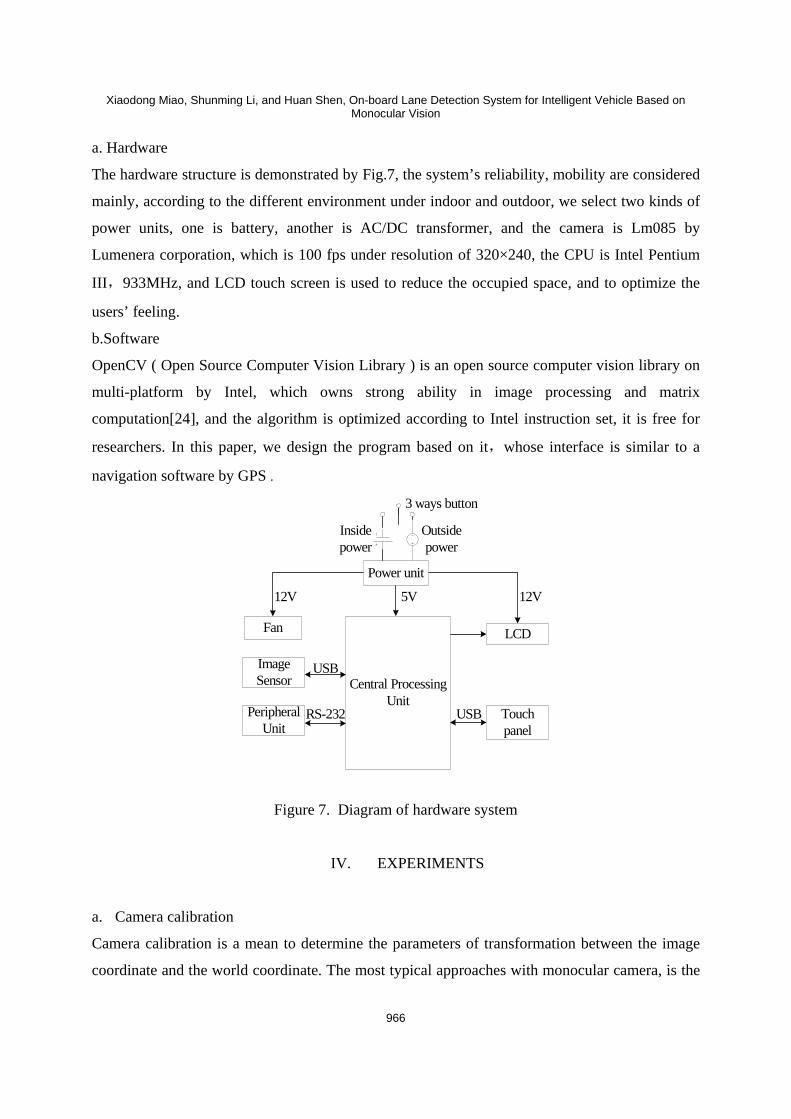
a. Hardware
The hardware structure is demonstrated by Fig.7, the system’s reliability, mobility are considered
mainly, according to the different environment under indoor and outdoor, we select two kinds of
power units, one is battery, another is AC/DC transformer, and the camera is Lm085 by
Lumenera corporation, which is 100 fps under resolution of 320×240, the CPU is Intel Pentium
III,933MHz, and LCD touch screen is used to reduce the occupied space, and to optimize the
users’ feeling.
b.Software
OpenCV ( Open Source Computer Vision Library ) is an open source computer vision library on
multi-platform by Intel, which owns strong ability in image processing and matrix
computation[24], and the algorithm is optimized according to Intel instruction set, it is free for
researchers. In this paper, we design the program based on it,whose interface is similar to a
navigation software by GPS .
Central Processing Unit
LCD
Touch panel
Peripheral Unit
Power unit
Fan
Image Sensor
12V 12V5V
USB
RS-232 USB
Outside power
Inside power
3 ways button
Figure 7. Diagram of hardware system
IV. EXPERIMENTS
a. Camera calibration
Camera calibration is a mean to determine the parameters of transformation between the image
coordinate and the world coordinate. The most typical approaches with monocular camera, is the
INTERNATIONAL JOURNAL ON SMART SENSING AND INTELLIGENT SYSTEMS, VOL. 5, NO. 4, DECEMBER 2012
967
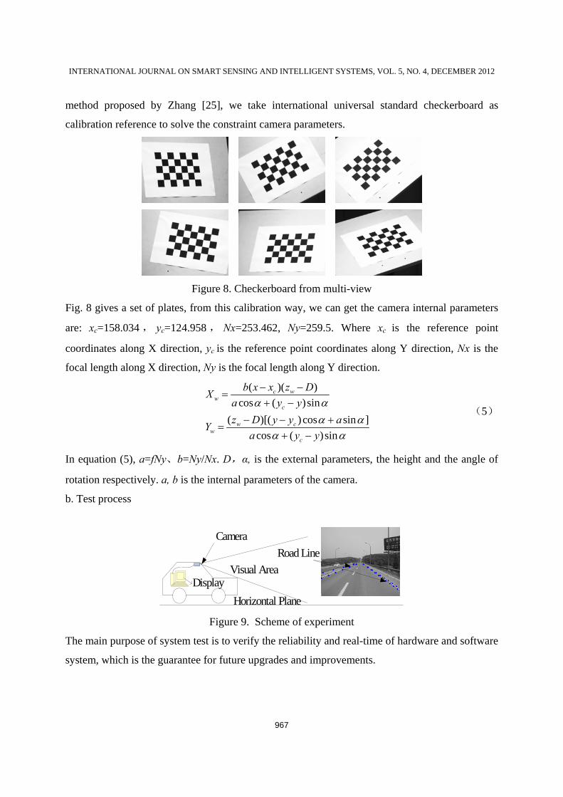
method proposed by Zhang [25], we take international universal standard checkerboard as
calibration reference to solve the constraint camera parameters.
Figure 8. Checkerboard from multi-view
Fig. 8 gives a set of plates, from this calibration way, we can get the camera internal parameters
are: xc=158.034 , yc=124.958 , Nx=253.462, Ny=259.5. Where xc is the reference point
coordinates along X direction, yc is the reference point coordinates along Y direction, Nx is the
focal length along X direction, Ny is the focal length along Y direction.
( )( )cos ( )sin
( )[( ) cos sin ]cos ( )sin
c ww
c
w cw
c
b x x z DXa y yz D y y aY
a y y
α αα α
α α
− −=
+ −
− − +=
+ −
(5)
In equation (5), a=fNy、b=Ny/Nx. D,α, is the external parameters, the height and the angle of
rotation respectively. a, b is the internal parameters of the camera.
b. Test process
Visual Area
Camera
Display
Road Line
Horizontal Plane Figure 9. Scheme of experiment
The main purpose of system test is to verify the reliability and real-time of hardware and software
system, which is the guarantee for future upgrades and improvements.
Xiaodong Miao, Shunming Li, and Huan Shen, On-board Lane Detection System for Intelligent Vehicle Based on Monocular Vision
968
Experiment scheme as shown in Fig 9, from the camera on the front glass, we collect the traffic
scene, and process with the system.
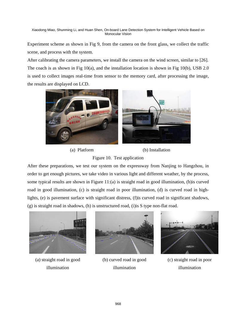
After calibrating the camera parameters, we install the camera on the wind screen, similar to [26].
The coach is as shown in Fig 10(a), and the installation location is shown in Fig 10(b), USB 2.0
is used to collect images real-time from sensor to the memory card, after processing the image,
the results are displayed on LCD.
(a) Platform (b) Installation
Figure 10. Test application
After these preparations, we test our system on the expressway from Nanjing to Hangzhou, in
order to get enough pictures, we take video in various light and different weather, by the process,
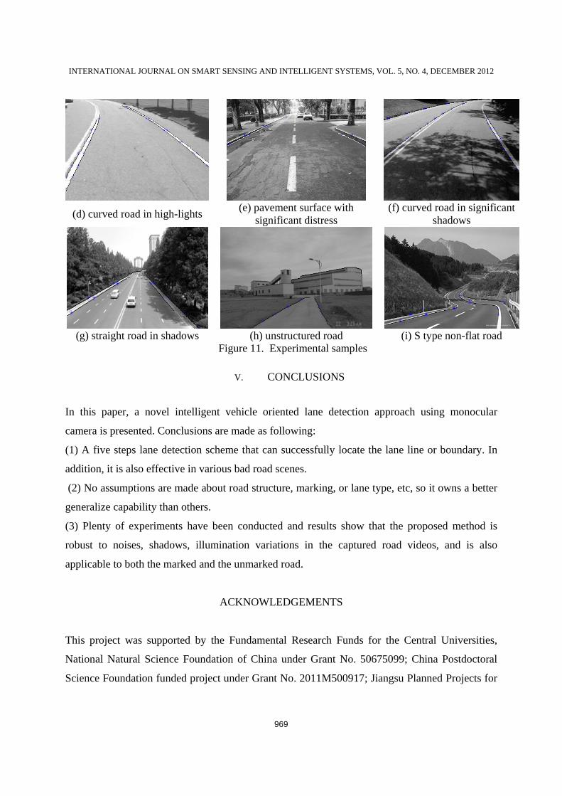
some typical results are shown in Figure 11:(a) is straight road in good illumination, (b)is curved
road in good illumination, (c) is straight road in poor illumination, (d) is curved road in high-
lights, (e) is pavement surface with significant distress, (f)is curved road in significant shadows,
(g) is straight road in shadows, (h) is unstructured road, (i)is S type non-flat road.
(a) straight road in good
illumination
(b) curved road in good
illumination
(c) straight road in poor
illumination
INTERNATIONAL JOURNAL ON SMART SENSING AND INTELLIGENT SYSTEMS, VOL. 5, NO. 4, DECEMBER 2012
969
(d) curved road in high-lights (e) pavement surface with
significant distress (f) curved road in significant
shadows
(g) straight road in shadows (h) unstructured road (i) S type non-flat road
Figure 11. Experimental samples
V. CONCLUSIONS
In this paper, a novel intelligent vehicle oriented lane detection approach using monocular
camera is presented. Conclusions are made as following:
(1) A five steps lane detection scheme that can successfully locate the lane line or boundary. In
addition, it is also effective in various bad road scenes.
(2) No assumptions are made about road structure, marking, or lane type, etc, so it owns a better
generalize capability than others.
(3) Plenty of experiments have been conducted and results show that the proposed method is
robust to noises, shadows, illumination variations in the captured road videos, and is also
applicable to both the marked and the unmarked road.
ACKNOWLEDGEMENTS
This project was supported by the Fundamental Research Funds for the Central Universities,
National Natural Science Foundation of China under Grant No. 50675099; China Postdoctoral
Science Foundation funded project under Grant No. 2011M500917; Jiangsu Planned Projects for
Xiaodong Miao, Shunming Li, and Huan Shen, On-board Lane Detection System for Intelligent Vehicle Based on Monocular Vision
970
Postdoctoral Research Funds under Grant No. 1101153C; and the Research Student Scientific
Research Innovation Program in Common University and College of Jiangsu Province under
Grant No.CXLX11_0180.
REFERENCES
[1] Liu Yuan, Wang Yuhao, Chen Siyue. “A hybrid MAC mechanism for multiple load
intelligent vehicle transportation network”, International Journal on Smart Sensing and
Intelligent Systems, 2011,Vol. 4, no. 4, pp. 662-674.
[2] A Broggi, S Berte. “A Vision Based Road Detection in Automotive Systems: A Real Time
Expectation Driven Approach”. Journal of Artificial Intelligence Research, 1995, no. 3: 325-
348.
[3] J Goldbeck, B Huertgen, S Ernst, L Kelch. “Lane following combining vision and DGPS”.
Image and Vision Computing, 2000, Vol. 18, no. 5, 425-433.
[4] Chen M, Jochem T, Pomerlean D. “Aurora: a vision-based roadway departure system”. Proc.
IEEE Conf. Intell. Robots and Systems, 1995, pp. 243-248.
[5] Kluge K, Lakshmanan S. “A deformable-template approach to lane detection”. Proc. IEEE
Intell. Vehicle Symp, 1995, pp. 54-59
[6] Bertozzi M., Broggi A. “Gold: a parallel real-time stereo vision system for generics obstacle
and lane detection”, IEEE Trans. Image Process, 1998. Vol. 7, no. 1, pp. 62 – 81.
[7] Kreucher C, Lakshmannan S. “Lana: a lane extraction algorithm that uses frequency domain
features”. IEEE Trans. Robot. Autom. 1999, Vol. 15, no.2, pp. 343-350.
[8] Wang Y., Teoh E.K, Shen D. “Lane detection using B-snake”.Int. Conf. Information
Intelligent and Systems, Bethesda, MD, USA, 1999, pp. 438-443.
[9] Wang Y., Shen D, Teoh E.K. “Lane detection using spline model”, Pattern Recognit. Lett.,
2000, Vol. 21, no. 8, pp. 677-689.
[10] Yim Y.U., Oh S.Y. “Three-feature based automatic lane detection algorithm (TFALDA) for
autonomous driving”, IEEE Trans. Intell. Transp. Syst, 2003, Vol. 4 , no. 4,pp. 219-225.
[11] Mccall J.C, Trivedi M.M. “Video-based lane estimation and tracking for driver assistance:
survey, system, and evaluation”, IEEE Trans. Intell. Transp. Syst., 2006, Vol. 7, no. 1, pp.
20-37.
INTERNATIONAL JOURNAL ON SMART SENSING AND INTELLIGENT SYSTEMS, VOL. 5, NO. 4, DECEMBER 2012
971
[12] Crisman J.D, Thorpe C.E. “SCARF: a color vision system that tracks roads and
intersections”, IEEE Trans. Robot. Autom. , 1993, Vol. 9, no. 1, pp. 49-58.
[13] Rasmussen C. “Grouping dominant orientations for ill-structured road following”. Proc.
IEEE Comp. Soc. Conf. Computer Vision and Pattern Recognition, July 2004, pp. 470-477.
[14] Gao Q, Luo Q, Moli S. “Rough set based unstructured road detection through feature
learning”. IEEE Int. Conf. Automation and Logistics, August 2007, pp. 101-106.
[15] Huang J, Kong B, Li B., Zheng F. “A new method of unstructured road detection based on
HSV color space and road feature”. Int. Conf. Information Acquisition, July 2007, pp. 596 –
601.
[16] Liu H.J, Zhang H.F, Lu J.F, Yang J.Y. “Quantitative evaluation and information fusion of
road edges for accurate unstructured road tracking”. Int. Conf. ITS Telecommunications,
June 2006, pp. 318-321.
[17] Dahlkamp H, Kaehler A, Stavens D, Thrun S, Bradski G. “Self-supervised monocular road
detection in desert terrain”. Robotics: Science a nd Systems, Philadelphia, PA, June 2006.
[18] D Pomerleau, T Jochem. “Rapidly Adapting Machine Vision for Automated Vehicle
Steering”. Machine Vision. 1996, Vol. 11, no. 2, pp.19-17.
[19] Y Wang, E K Teoh, D Shen. “Lane detection and tracking using B-snake”. Image Visual
Compute, 2004, Vol. 22, no. 4, pp.269-280.
[20] Z W Kim. “Robust Lane Detection and Tracking in Challenging Scenarios”. IEEE
Transactions on Intelligent Transportation System, 2008, Vol. 9, no. 1, pp.16-26.
[21] Kun Qian, Xudong Ma, Xian Zhong Dai, et al. “Spatial-temporal Collaborative Sequential
Monte Carlo for Mobile Robot Localization in Distributed Intelligent Environments”.
International Journal on Smart Sensing and Intelligent Systems, 2012, Vol. 5, no. 2, pp. 295-
314.
[22] Cretu, A.-M.; Payeur, P. Biologically-inspired visual attention features for a vehicle
classification task. International Journal on Smart Sensing and Intelligent Systems, 2011,Vol.
4, no. 3, pp. 402-423.
[23] Shen Huan,Li Shunming, Miao Xiaodong, et al. “Intelligent Vehicles Oriented Lane
Detection Approach under Bad Road Scene”. IEEE the Ninth International Conference on
Computer and Information Technology. Xiamen, China, 2009, pp.177-182.
[24] S. S. Huang, C. J. Chen, P. Y. Hsiao, and L. C. Fu, “On-Board Vision System for Lane

Xiaodong Miao, Shunming Li, and Huan Shen, On-board Lane Detection System for Intelligent Vehicle Based on Monocular Vision
972
Recognition and Front-Vehicle Detection to Enhance Driver’s Awareness”, IEEE
International Conference on Robotics and Automation, 2004, 2456-2461.
[25] Z. Zhang. “A Flexible New Technique for Camera Calibration”. Transactions on Pattern
Analysis and Machine Intelligence, 2000, Vol. 19, no. 11, pp.1330-1334.
[26] Yingying Huang, Ross McMurran. “Development of an automated testing system for vehicle
infotainment system”. Advanced Manufacturing Technology. 2010. Vol. 51, no. 14, pp.233-
246.
Related Documents