English 115 48 72-27 Rev. 1 Operator’s Manual ST230E Gasoline containing up to 10% ethanol (E10) is acceptable for use in this machine. The use of any gasoline exceeding 10% ethanol (E10) will void the product warranty. Please read the owner's manual carefully and make sure you understand the instructions before using the machine.

Welcome message from author
This document is posted to help you gain knowledge. Please leave a comment to let me know what you think about it! Share it to your friends and learn new things together.
Transcript

English115 48 72-27 Rev. 1
Operator’s ManualST230E
Gasoline containing up to 10% ethanol (E10) is acceptable for use in this machine. The use of any gasoline exceeding 10% ethanol (E10) will void the product warranty.
Please read the owner's manual carefully and make sure you understand the instructions before using the machine.
2
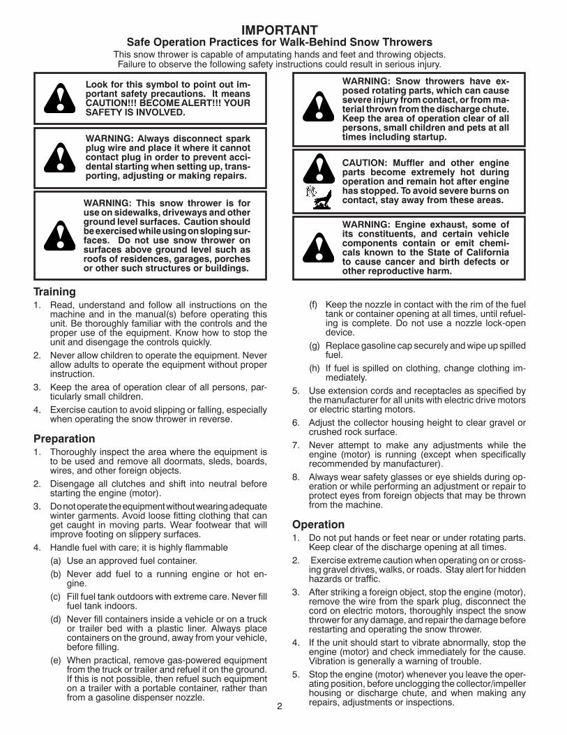
IMPORTANTSafe Operation Practices for Walk-Behind Snow Throwers
This snow thrower is capable of amputating hands and feet and throwing objects.Failure to observe the following safety instructions could result in serious injury.
WARNING: This snow thrower is for use on sidewalks, driveways and other ground level surfaces. Caution should be exercised while using on sloping sur-faces. Do not use snow thrower on surfaces above ground level such as roofs of residences, garages, porch es or other such structures or buildings.
WARNING: Snow throwers have ex- posed rotating parts, which can cause severe injury from contact, or from ma-terial thrown from the discharge chute. Keep the area of operation clear of all persons, small children and pets at all times including startup.WARNING: Always disconnect spark
plug wire and place it where it can not con tact plug in order to pre vent ac ci -den tal start ing when setting up, trans- port ing, ad just ing or making re pairs.
Look for this symbol to point out im- por tant safety precautions. It meansCAUTION!!! BE COME ALERT!!! YOUR SAFE TY IS IN VOLVED.
CAUTION: Muffler and other engine parts become extremely hot during operation and remain hot after engine has stopped. To avoid severe burns on contact, stay away from these areas.
WARNING: Engine exhaust, some of its con stit u ents, and certain vehicle com po nents contain or emit chem i-cals known to the State of Cal i for nia to cause can cer and birth defects or oth er re pro duc tive harm.
(f) Keep the nozzle in contact with the rim of the fuel tank or container opening at all times, until refuel-ing is complete. Do not use a nozzle lock-open device.
(g) Replace gasoline cap securely and wipe up spilled fuel.
(h) If fuel is spilled on clothing, change clothing im-mediately.
5. Use extension cords and receptacles as specified by the manufacturer for all units with electric drive motors or electric starting motors.
6. Adjust the collector housing height to clear gravel or crushed rock surface.
7. Never attempt to make any adjustments while the engine (motor) is running (except when specifically recommended by manufacturer).
8. Always wear safety glasses or eye shields during op-eration or while performing an adjustment or repair to protect eyes from foreign objects that may be thrown from the machine.
Operation1. Do not put hands or feet near or under rotating parts.
Keep clear of the discharge opening at all times.2. Exercise extreme caution when operating on or cross-
ing gravel drives, walks, or roads. Stay alert for hidden hazards or traffic.
3. After striking a foreign object, stop the engine (motor), remove the wire from the spark plug, disconnect the cord on electric motors, thoroughly inspect the snow thrower for any damage, and repair the damage before restarting and operating the snow thrower.
4. If the unit should start to vibrate abnormally, stop the engine (motor) and check immediately for the cause. Vibration is generally a warning of trouble.
5. Stop the engine (motor) whenever you leave the oper-ating position, before unclogging the collector/impeller housing or discharge chute, and when making any repairs, adjustments or inspections.
Training1. Read, understand and follow all instructions on the
machine and in the manual(s) before operating this unit. Be thoroughly familiar with the controls and the proper use of the equipment. Know how to stop the unit and disengage the controls quickly.
2. Never allow children to operate the equipment. Never allow adults to operate the equipment without proper instruction.
3. Keep the area of operation clear of all persons, par-ticularly small children.
4. Exercise caution to avoid slipping or falling, especially when operating the snow thrower in reverse.
Preparation1. Thoroughly inspect the area where the equipment is
to be used and remove all doormats, sleds, boards, wires, and other foreign objects.
2. Disengage all clutches and shift into neutral before starting the engine (motor).
3. Do not operate the equipment without wearing adequate winter garments. Avoid loose fitting clothing that can get caught in moving parts. Wear footwear that will improve footing on slippery surfaces.
4. Handle fuel with care; it is highly flammable(a) Use an approved fuel container.(b) Never add fuel to a running engine or hot en-
gine.(c) Fill fuel tank outdoors with extreme care. Never fill
fuel tank indoors.(d) Never fill containers inside a vehicle or on a truck
or trailer bed with a plastic liner. Always place containers on the ground, away from your vehicle, before filling.
(e) When practical, remove gas-powered equipment from the truck or trailer and refuel it on the ground. If this is not possible, then refuel such equipment on a trailer with a portable container, rather than from a gasoline dispenser nozzle.

3
CONGRATULATIONS on your purchase of a new snow thrower. It has been designed, engineered and man u fac -tured to give best possible dependability and per for mance.
Should you experience any problem you cannot easily remedy, please contact your nearest authorized service center. We have competent, well-trained tech ni cians and the proper tools to service or repair this unit.
Please read and retain this manual. The instructions will enable you to assemble and maintain your snow thrower prop er ly. Always observe the “SAFETY RULES”.
SERIAL NUMBER: ___________________________
DATE OF PURCHASE: _______________________
THE MODEL AND SERIAL NUMBERS WILL BE FOUND ON A DECAL ATTACHED TO THE REAR OF THE SNOW THROWER HOUSING.
YOU SHOULD RECORD BOTH SERIAL NUMBER AND DATE OF PURCHASE AND KEEP IN A SAFE PLACE FOR FUTURE REFERENCE.
CUSTOMER RESPONSIBILITIES• Read and observe the safety rules.• Follow a regular schedule in maintaining, caring for
and using your snow thrower.• Follow the instructions under “Maintenance” and “Stor-
age” sec tions of this own er’s manual.
6. When cleaning, repairing or inspecting the snow thrower, stop the engine and make certain the collector/impel-ler and all moving parts have stopped. Disconnect the spark plug wire and keep the wire away from the plug to prevent someone from accidentally starting the engine.
7. Do not run the engine indoors, except when starting the engine and for transporting the snow thrower in or out of the building. Open the outside doors; exhaust fumes are dangerous.
8. Exercise extreme caution when operating on slopes.9. Never operate the snow thrower without proper guards,
and other safety protective devices in place and work-ing.
10. Never direct the discharge toward people or areas where property damage can occur. Keep children and others away.
11. Do not overload the machine capacity by attempting to clear snow at too fast a rate.
12. Never operate the machine at high transport speeds on slippery surfaces. Look behind and use care when operating in reverse.
13. Disengage power to the collector/impeller when snow thrower is transported or not in use.
14. Use only attachments and accessories approved by the manufacturer of the snow thrower (such as wheel weights, counterweights, or cabs).
15. Never operate the snow thrower without good visibility or light. Always be sure of your footing, and keep a firm hold on the handles. Walk; never run.
16. Never touch a hot engine or muffler.
Clearing a Clogged Discharge ChuteHand contact with the rotating impeller inside the discharge chute is the most common cause of injury associated with snow throwers. Never use your hand to clean out the dis-charge chute. To clear the chute:1. SHUT THE ENGINE OFF!2. Wait 10 seconds to be sure the impeller blades have
stopped rotating.3. Always use a clean-out tool, not your hands.
Maintenance and Storage1. Check shear bolts and other bolts at frequent intervals
for proper tightness to be sure the equipment is in safe working condition.
2. Never store the machine with fuel in the fuel tank inside a building where ignition sources are present such as hot water heaters, space heaters, or clothes dryers. Allow the engine to cool before storing in any enclosure.
3. Always refer to operator’s manual for important details if the snow thrower is to be stored for an extended period.
4. Maintain or replace safety and instruction labels, as necessary.
5. Run the machine a few minutes after throwing snow to prevent freeze-up of the collector/impeller.
MAINTENANCE ..................................................... 15-16SERVICE AND AD JUST MENTS ........................... 17-19STORAGE ................................................................... 20TROU BLE SHOOT ING ................................................ 21WARRANTY ........................................................... 22-25
SAFETY RULES ........................................................ 2-3PRODUCT SPECIFICATIONS ...................................... 3CUSTOMER RESPONSIBILITIES ................................ 3ASSEMBLY / PRE-OPERATION ............................... 5-7OPERATION ............................................................ 8-14MAINTENANCE SCHEDULE ..................................... 15
TABLE OF CONTENTS
PRODUCT SPECIFICATIONSGasoline Capacity 3.2 Quarts (3,03 Liters)and Type: Unleaded Regular only
Oil Type SAE 5W-30 or 10W-30(API SG–SL): (0°F to +40°F / –18°C to +5°C) Synthetic SAE 5W-30 or 10W-30 (below 0°F / –18°C)
Oil Capacity: 28 Ounces (0,8 Liters)
Spark Plug: Champion 696798Gap: 0.030" (0,762 mm)
4
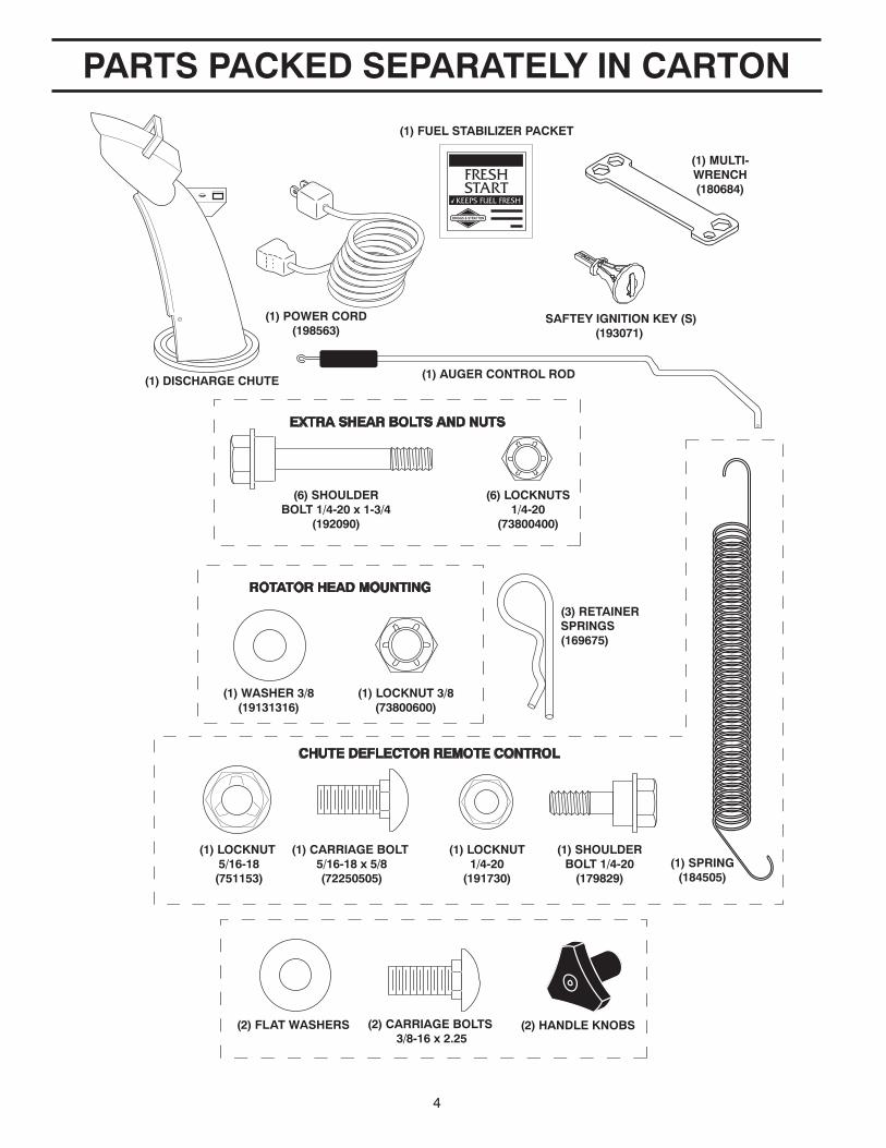
PARTS PACKED SEPARATELY IN CARTON
(1) POWER CORD(198563)
(1) DISCHARGE CHUTE
(6) SHOULDERBOLT 1/4-20 x 1-3/4
(192090)
(1) WASHER 3/8(19131316)
(1) LOCKNUT 5/16-18
(751153)
(1) CARRIAGE BOLT 5/16-18 x 5/8(72250505)
(1) LOCKNUT1/4-20
(191730)
(1) SHOULDERBOLT 1/4-20
(179829)(1) SPRING
(184505)
(1) LOCKNUT 3/8(73800600)
(3) RETAINER SPRINGS
(169675)
(6) LOCKNUTS1/4-20
(73800400)
EXTRA SHEAR BOLTS AND NUTS
ROTATOR HEAD MOUNTING
CHUTE DEFLECTOR REMOTE CONTROL
(1) AUGER CONTROL ROD
SAFTEY IGNITION KEY (S)(193071)
(1) FUEL STABILIZER PACKET
(1) MULTI-WRENCH(180684)
(2) FLAT WASHERS (2) CARRIAGE BOLTS 3/8-16 x 2.25
(2) HANDLE KNOBS
5
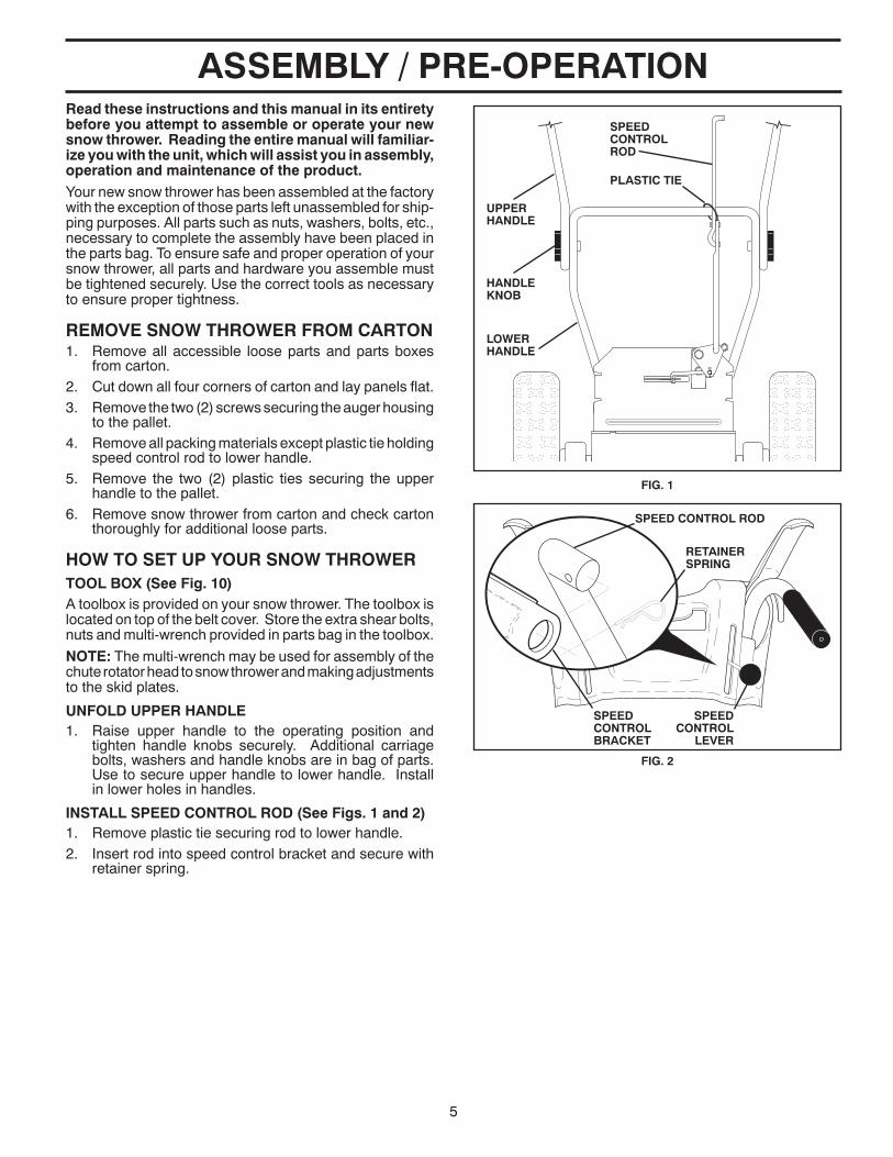
ASSEMBLY / PRE-OPERATIONRead these instructions and this manual in its entirety before you attempt to assemble or operate your new snow thrower. Reading the entire manual will familiar-ize you with the unit, which will assist you in assembly, operation and maintenance of the product.Your new snow thrower has been as sem bled at the factory with the ex cep tion of those parts left unassembled for ship-ping purposes. All parts such as nuts, washers, bolts, etc., necessary to com plete the as sem bly have been placed in the parts bag. To ensure safe and proper operation of your snow thrower, all parts and hard ware you assemble must be tightened se cure ly. Use the correct tools as nec es sary to ensure proper tightness.
REMOVE SNOW THROWER FROM CAR TON1. Remove all accessible loose parts and parts boxes
from carton.2. Cut down all four corners of carton and lay panels flat.3. Remove the two (2) screws securing the auger housing
to the pallet.4. Remove all packing materials ex cept plastic tie holding
speed control rod to lower handle.5. Remove the two (2) plastic ties securing the upper
handle to the pallet.6. Remove snow thrower from carton and check carton
thor ough ly for ad di tion al loose parts.
HOW TO SET UP YOUR SNOW THROWER TOOL BOX (See Fig. 10)A toolbox is provided on your snow thrower. The toolbox is located on top of the belt cover. Store the extra shear bolts, nuts and multi-wrench provided in parts bag in the toolbox.
NOTE: The multi-wrench may be used for assembly of the chute rotator head to snow thrower and making ad just ments to the skid plates.
UNFOLD UPPER HANDLE1. Raise upper handle to the operating position and
tight en handle knobs securely. Additional carriage bolts, washers and handle knobs are in bag of parts. Use to secure upper handle to lower handle. Install in lower holes in handles.
INSTALL SPEED CONTROL ROD (See Figs. 1 and 2)1. Remove plastic tie securing rod to lower handle.2. Insert rod into speed control bracket and secure with
retainer spring.
SPEED CON TROL ROD
SPEED CONTROL BRACKET
SPEED CONTROL
LEVER
FIG. 2
RETAINER SPRING
SPEEDCONTROL ROD
HANDLE KNOB
LOWER HANDLE
PLASTIC TIE
UPPER HANDLE
FIG. 1
6
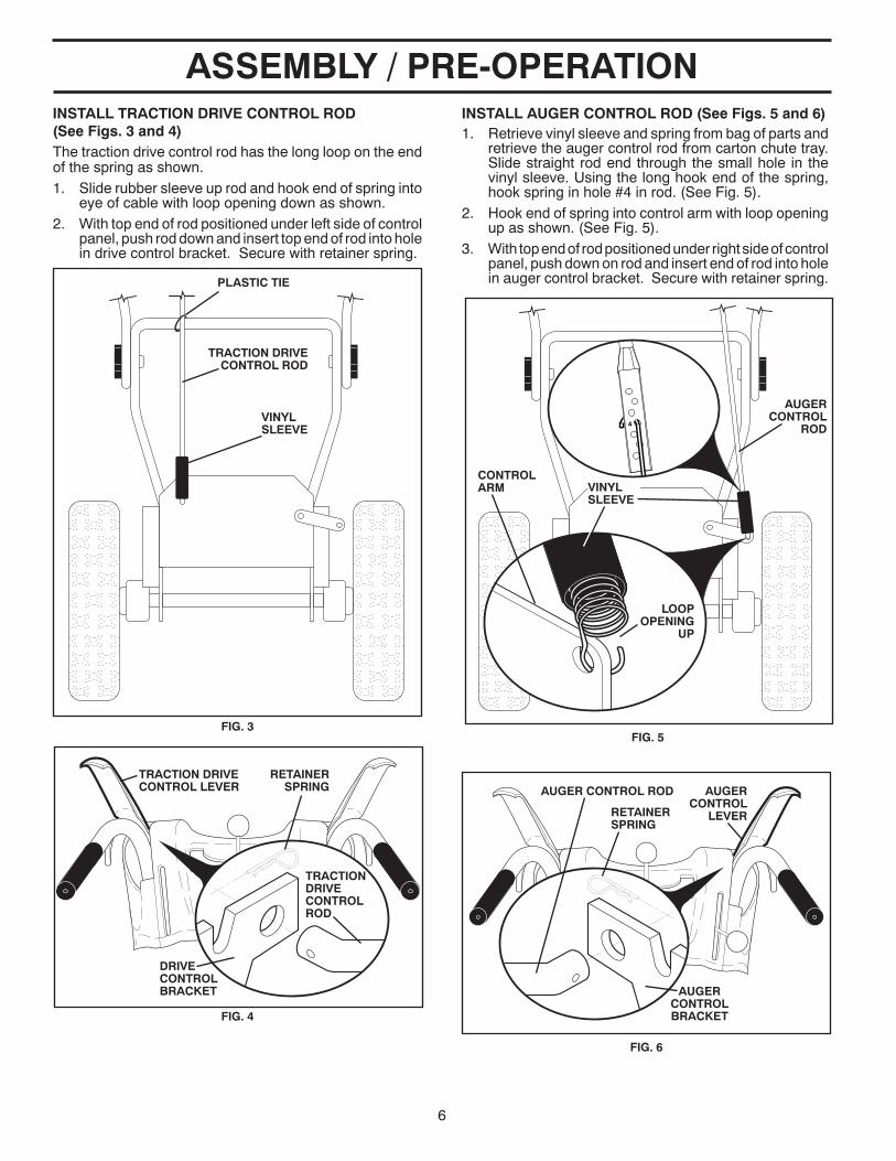
ASSEMBLY / PRE-OPERATION
AUGERCONTROL
LEVER
AUGER CONTROL ROD
AUGERCONTROL BRACKET
RETAINER SPRING
FIG. 6
INSTALL TRACTION DRIVE CONTROL ROD(See Figs. 3 and 4)The traction drive control rod has the long loop on the end of the spring as shown.1. Slide rubber sleeve up rod and hook end of spring into
eye of cable with loop opening down as shown.2. With top end of rod positioned under left side of control
panel, push rod down and insert top end of rod into hole in drive control bracket. Secure with retainer spring.
TRACTION DRIVE CON TROL ROD
DRIVECONTROL BRACKET
RETAINER SPRING
TRACTION DRIVE CON TROL LEVER
FIG. 4
TRACTION DRIVECONTROL ROD
VINYL SLEEVE
FIG. 3
PLASTIC TIE
INSTALL AUGER CONTROL ROD (See Figs. 5 and 6)1. Retrieve vinyl sleeve and spring from bag of parts and
retrieve the auger control rod from carton chute tray. Slide straight rod end through the small hole in the vinyl sleeve. Using the long hook end of the spring, hook spring in hole #4 in rod. (See Fig. 5).
2. Hook end of spring into control arm with loop opening up as shown. (See Fig. 5).
3. With top end of rod positioned under right side of control panel, push down on rod and insert end of rod into hole in auger control bracket. Secure with retainer spring.
AUGERCONTROL
ROD
CONTROL ARM VINYL
SLEEVE
LOOP OPENING
UP
FIG. 5

7
ASSEMBLY / PRE-OPERATIONINSTALL DISCHARGE CHUTE / CHUTE ROTATER HEAD (See Fig. 7)NOTE: The multi-wrench provided in your parts bag may be used to install the chute rotater head.1. Place discharge chute assembly on top of chute base
with discharge opening toward front of snow thrower.2. Position chute rotater head over chute bracket. If nec es -
sary, rotate chute assembly to align square and pin on un- der side of chute rotater head with holes in chute brack et.
3. With chute rotater head and chute bracket aligned, po si tion chute rotater head on pin and threaded stud of mounting bracket.
4. Install 3/8 washer and locknut on threaded stud and tighten securely.
CHECK TIRE PRESSUREThe tires on your snow thrower were overinflated at the fac-tory for shipping purposes. Correct and equal tire pres sure is important for best snow throwing performance.• Reduce tire pressure to 14-17 PSI.
CHUTEROTATER HEAD
3/8 WASHER
3/8 LOCKNUT
THREADED STUD
PIN
ROTATER HEAD MOUNT ING BRACKET
CHUTE BRACKET
FIG. 7
ALIGN BEFORETIGHTENING LOCKNUT
FIG. 8
INSTALL CHUTE DEFLECTOR REMOTE CONTROL (See Figs. 8 and 9)1. Install remote cable bracket to discharge chute with
5/16-18 carriage bolt and 5/16-18 locknut as shown. Tighten securely.
2. Install remote cable eyelet to chute deflector with1/4-20 shoulder bolt and 1/4-20 locknut as shown. Tighten nut securely. Cable eyelet will be loose on shoulder bolt.
3. Install spring hooks between hex nuts on chute rotater head and into hole in chute deflector as shown.
HOOKBE TWEEN HEX NUTSON CHUTEROTATER HEAD
SPRINGCHUTE
DE FLEC TOR
5/16-18 CARRIAGE
BOLT
5/16-18LOCKNUT
REMOTE CABLE
BRACKET
1/4-20 LOCK NUT
CABLEEYELET
1/4-20 SHOULDER BOLT
CHUTE DEFLECTOR CONTROL LEVER
FIG. 9
8
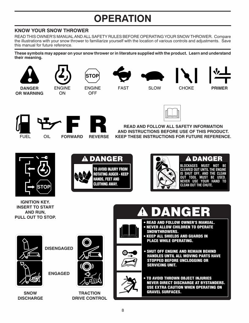
OPERATIONKNOW YOUR SNOW THROWERREAD THIS OWNER'S MANUAL AND ALL SAFETY RULES BEFORE OPERATING YOUR SNOW THROWER. Compare the illustrations with your snow thrower to familiarize yourself with the location of various controls and adjustments. Save this manual for future reference.
These symbols may appear on your snow thrower or in literature supplied with the product. Learn and understand their meaning.
FORWARD
PRIMER
IGNITION KEY.INSERT TO START
AND RUN,PULL OUT TO STOP.
READ AND FOLLOW ALL SAFETY INFORMATIONAND INSTRUCTIONS BEFORE USE OF THIS PRODUCT.
KEEP THESE INSTRUCTIONS FOR FUTURE REFERENCE.
DANGEROR WARNING
REVERSE
SNOWDISCHARGE
TRACTIONDRIVE CONTROL
DISENGAGED
ENGAGED

9
OPERATION
Traction drive control lever - used to engage power-pro pelled for ward or reverse motion of snow thrower.
LH and RH turn triggers - used to steer the snow thrower.
Auger control lever - used to engage auger motion (throw snow).
Deflector remote control lever - used to change the dis tance the snow is thrown.
Discharge chute control lever - used to change the di rec tion the snow is thrown.
Skid plate - used to adjust height of scraper bar from the ground.
Drift cutter - used to cut through deep snowdrifts.
Toolbox - used to store spare shear bolts, locknuts and wrench.
Safety ignition key - must be inserted for the engine to start and run. Remove when snow thrower is not in use.
Electric start button – used for starting the engine.
Recoil (auxiliary) starter handle – used for start ing the en gine.
Primer - pumps additional fuel from the carburetor to the cylinder for use when starting a cold engine.
Throttle/engine control - used to se lect either FAST or SLOW engine speed and to STOP the engine.
Choke control - used for starting a cold engine.
Drive speed control lever - used to select forward or reverse motion and speed of snow thrower.
MEETS A.N.S.I. SAFETY REQUIREMENTSOur snow throwers conform to the standards of the American National Standards Institute.
TRACTION DRIVE
CONTROL LEVER
DISCHARGE CHUTE CONTROL LEVER
DRIVE SPEED CON TROL LEVER
AUGER CONTROL LEVER
MUF FLER
TOOLBOX
HANDLE KNOB
SKID PLATE
CHUTEDE FLEC TOR
NOTE: ITEMS ABOVE ARE SHOWN IN THEIR TYPICAL
LOCATION ON THE ENGINE. ACTUAL
LOCATION MAY VARY WITH THE ENGINE
ON YOUR UNIT.
FIG. 10
AU GERS
DISCHARGE CHUTE
CLEAN-OUT TOOL
LIGHT
LH TURN TRIGGER
DRIFT CUTTER
RECOIL (AUXILIARY)
STARTER HANDLE
THROTTLE / ENGINE CONTROL
MUF FLER
GAS O LINE FILLER CAP
SAFETY IGNITION KEY
CHOKE CON- TROL
ELECTRIC START
BUTTON
PRIM ER
FUEL SHUT-OFF VALVE
DEFLECTOR REMOTECONTROL LEVER
10
The operation of any snow thrower can result in foreign objects thrown into the eyes, which can result in severe eye damage. Always wear safety glasses or eye shields while operating your snow thrower or performing any ad just-
ments or repairs. We recommend standard safe ty glasses or a wide vision safety mask worn over spectacles.
HOW TO USE YOUR SNOW THROWERKnow how to operate all controls before adding fuel or attempting to start the engine.
STOPPINGTRACTION DRIVE• Release traction drive control lever to stop the forward
or reverse movement of the snow thrower.
AUGER• Release the auger control lever to stop throwing snow.
ENGINE1. Move throttle control to “STOP” position.2. Remove (do not turn) safety ignition key to prevent
unauthorized use.
NOTE: Never use choke to stop engine.
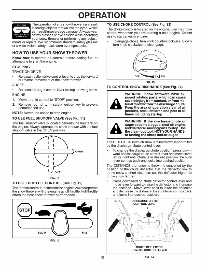
TO USE FUEL SHUT-OFF VALVE (See Fig. 11)The fuel shut-off valve is located beneath the fuel tank on the engine. Always op er ate the snow thrower with the fuel shut-off valve in the OPEN position.
OPERATION
TO USE THROTTLE CONTROL (See Fig. 12)The throttle control is located on the engine. Always op er ate the snow thrower with the engine at full throttle. Full throttle offers the best snow thrower performance.
FIG. 11
OPEN
OFF
FIG. 12
SLOW FAST
FIG. 13
FULLOFF
TO USE CHOKE CON TROL (See Fig. 13)The choke con trol is located on the en gine. Use the choke control when ev er you are starting a cold en gine. Do not use to start a warm en gine.• To engage choke, turn knob counterclockwise. Slowly
turn knob clockwise to disengage.
TO CONTROL SNOW DISCHARGE (See Fig. 14)
WARNING: Snow throwers have ex- posed rotating parts, which can cause severe injury from contact, or from ma-terial thrown from the discharge chute. Keep the area of operation clear of all persons, small children and pets at all times including startup.
WARNING: If the discharge chute or au ger become clogged, shut-off en gine and wait for all moving parts to stop. Use the clean-out tool, NOT YOUR HANDS, to un clog the chute and/or auger.
The DIRECTION in which snow is to be thrown is controlled by the discharge chute control lever.• To change the discharge chute position, press down-
ward on discharge chute control lever and move lever left or right until chute is in desired position. Be sure lever springs back and locks into desired position.
The DISTANCE that snow is thrown is controlled by the position of the chute deflector. Set the deflector low to throw snow a short distance; set the deflector higher to throw snow farther.• Press downward on chute deflector control lever and
move lever forward to raise the deflector and increase the distance. Move lever back to lower the deflector and decrease the distance. Be sure lever springs back and locks into desired position.
FIG. 14
DISCHARGE CHUTECONTROL LEVER
CHUTE DEFLECTORREMOTE CONTROL LEVER
11
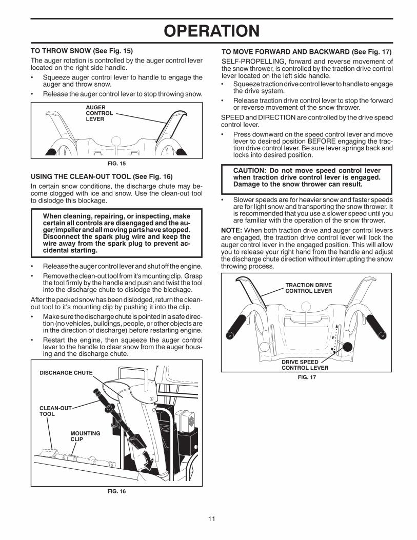
OPERATIONTO THROW SNOW (See Fig. 15)The auger rotation is controlled by the auger control lever located on the right side handle.• Squeeze auger control lever to handle to engage the
auger and throw snow.• Release the auger control lever to stop throwing snow.
USING THE CLEAN-OUT TOOL (See Fig. 16)In certain snow conditions, the discharge chute may be-come clogged with ice and snow. Use the clean-out tool to dislodge this blockage.
When cleaning, repairing, or in spect ing, make certain all controls are disengaged and the au-ger/impeller and all moving parts have stopped. Disconnect the spark plug wire and keep the wire away from the spark plug to prevent ac-cidental starting.
• Release the auger control lever and shut off the engine.• Remove the clean-out tool from it's mounting clip. Grasp
the tool firmly by the handle and push and twist the tool into the discharge chute to dislodge the blockage.
After the packed snow has been dislodged, return the clean-out tool to it's mounting clip by pushing it into the clip.• Make sure the discharge chute is pointed in a safe direc-
tion (no vehicles, buildings, people, or other objects are in the direction of discharge) before restarting engine.
• Restart the engine, then squeeze the auger control lever to the handle to clear snow from the auger hous-ing and the discharge chute.
CLEAN-OUT TOOL
FIG. 16
MOUNTING CLIP
DISCHARGE CHUTE
AUGER CONTROL LEVER
FIG. 15
DRIVE SPEEDCONTROL LEVER
TRACTION DRIVE CONTROL LEVER
FIG. 17
TO MOVE FORWARD AND BACKWARD (See Fig. 17)SELF-PROPELLING, forward and reverse movement of the snow thrower, is controlled by the traction drive control lever located on the left side handle.• Squeeze traction drive control lever to handle to en gage
the drive system.• Release traction drive control lever to stop the forward
or reverse movement of the snow thrower.
SPEED and DIRECTION are controlled by the drive speed control lever.• Press downward on the speed control lever and move
lever to de sired po si tion BE FORE engaging the trac- tion drive control lever. Be sure lever springs back and locks into desired position.
CAUTION: Do not move speed con trol le ver when traction drive control lever is en gaged. Damage to the snow thrower can result.
• Slower speeds are for heavier snow and faster speeds are for light snow and transporting the snow thrower. It is recommended that you use a slower speed until you are familiar with the operation of the snow thrower.
NOTE: When both traction drive and auger control levers are engaged, the traction drive control lever will lock the auger control lever in the engaged position. This will allow you to release your right hand from the handle and adjust the discharge chute direction without interrupting the snow throwing process.
12
POWER STEERING OPERATION (See Fig. 18)Steering triggers are used to assist in steering your snow thrower. The triggers are located on the underside of each handle. When a trigger is squeezed, it disengages the drive wheel on that side of snow thrower and allows it to turn in that direction.• To turn left – squeeze left side trigger.• To turn right – squeeze right side trigger.
LH TURN TRIGGER
RH TURNTRIGGER
FIG. 18
OPERATION
BEFORE STARTING THE ENGINECHECK ENGINE OIL LEVEL (See Fig. 21)The engine on your snow thrower has been shipped from the factory already filled with oil.1. Check engine oil with snow thrower on level ground.2. Remove oil fill cap/dipstick and wipe clean, reinsert
the dipstick and screw tight, wait for a few seconds, remove and read oil level. If necessary, add oil until “FULL” mark on dipstick is reached. Do not overfill.
• To change engine oil, see “TO CHANGE ENGINE OIL” in the Main te nance sec tion of this manual.
ADD GASOLINE (See Fig. 21)• Fill fuel tank to bottom of tank filler neck. Do not over-
fill. Use fresh, clean, regular unleaded gasoline with a minimum of 87 octane. Do not mix oil with gasoline. Purchase fuel in quan ti ties that can be used within 30 days to assure fuel freshness.
WARNING: Wipe off any spilled oil or fuel. Do not store, spill or use gasoline near an open flame.
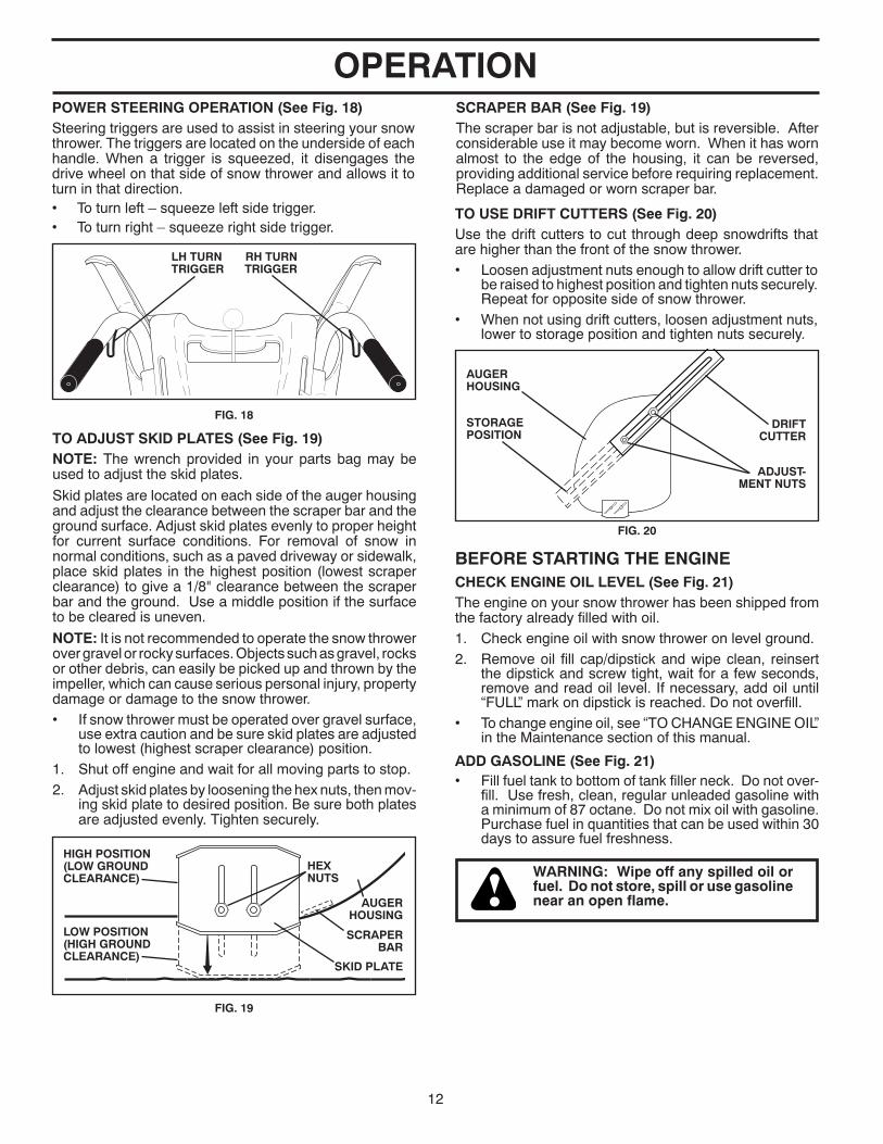
TO ADJUST SKID PLATES (See Fig. 19)NOTE: The wrench provided in your parts bag may be used to adjust the skid plates.
Skid plates are located on each side of the auger housing and adjust the clearance between the scraper bar and the ground surface. Adjust skid plates evenly to proper height for current surface conditions. For removal of snow in normal con di tions, such as a paved driveway or side walk, place skid plates in the highest position (lowest scraper clear ance) to give a 1/8" clearance between the scraper bar and the ground. Use a middle position if the surface to be cleared is uneven.
NOTE: It is not recommended to operate the snow thrower over gravel or rocky surfaces. Objects such as gravel, rocks or other debris, can easily be picked up and thrown by the impeller, which can cause serious personal injury, property dam age or damage to the snow thrower. • If snow thrower must be operated over gravel surface,
use extra caution and be sure skid plates are adjusted to lowest (highest scraper clear ance) position.
1. Shut off engine and wait for all moving parts to stop.2. Adjust skid plates by loosening the hex nuts, then mov-
ing skid plate to desired position. Be sure both plates are adjusted evenly. Tighten securely.
SKID PLATE
LOW POSITION (HIGH GROUND CLEAR ANCE)
HEX NUTS
HIGH POSITION(LOW GROUNDCLEARANCE)
AUGER HOUSING
FIG. 19
SCRAPER BAR
SCRAPER BAR (See Fig. 19)The scraper bar is not adjustable, but is reversible. After con sid er able use it may become worn. When it has worn almost to the edge of the housing, it can be reversed, providing additional service before requiring replacement. Replace a dam aged or worn scrap er bar.
TO USE DRIFT CUTTERS (See Fig. 20)Use the drift cutters to cut through deep snowdrifts that are higher than the front of the snow thrower.• Loosen adjustment nuts enough to allow drift cutter to
be raised to highest position and tighten nuts securely. Repeat for opposite side of snow thrower.
• When not using drift cutters, loosen adjustment nuts, lower to storage position and tighten nuts securely.
ADJUST-MENT NUTS
STORAGE POSITION
AUGER HOUSING
DRIFT CUTTER
FIG. 20

13
OPERATION
ENGINE OILFILL CAP / DIPSTICK
FUEL SHUT-OFF VALVE
PRIM ER
SAFETY IG NI TION KEY THROT TLE
CHOKE CONTROL
STARTER BUTTON
RECOIL STARTER HANDLE
GAS O LINE FILLER CAP
NOTE: ALL ITEMS ARE SHOWN IN THEIR TYPICAL LOCATION. ACTUAL LOCATION MAY VARY WITH ENGINE ON YOUR UNIT.
FIG. 21
TO START ENGINE • Be sure fuel shut-off valve is in the “OPEN” position.
Your snow thrower engine is equipped with both a 120 Volt A.C. electric starter and a recoil starter. The electric starter is equipped with a three-wire power cord and plug and is designed to operate on 120 Volt A.C. household current.• Be sure your house is a 120 Volt A.C. three-wire
ground ed system. If you are uncertain, consult a li censed electrician.
WARNING: Do not use the electric start er if your house is not a 120 Volt A.C. three-wire grounded system. Se ri- ous per son al injury or damage to your snow thrower could result.
COLD START - ELECTRIC STARTER1. Insert safety ignition key (Tied to recoil start cord.) into
ignition slot until it clicks. DO NOT turn the key. Keep the extra safety ignition key in a safe place.
2. Place throttle control in “FAST” position.3. Rotate choke control to “FULL” position.4. Connect the power cord to the engine.5. Plug the other end of the power cord into a three-hole
grounded 120 Volt A.C. receptacle.
NOTE: Do not use primer when start ing en gine with the electric starter.6. Push starter button until engine starts.
IMPORTANT: Do not crank engine more than five con tin u- ous seconds between each time you try to start. Wait 5 to 10 seconds between each attempt.7. When the engine starts, release the starter button and
slowly move the choke control to the “OFF” position.8. Disconnect the power cord from the receptacle first,
then from the engine.
Allow the engine to warm up for a few minutes. Engine will not develop full power until it has reached normal operat-ing temperature.
WARM START - ELECTRIC STARTER
Follow the steps above, keeping the choke control in the “OFF” position.
COLD START - RECOIL STARTER1. Insert safety ignition key (Tied to recoil start cord) into
ignition slot until it clicks. DO NOT turn the key. Keep the extra safety ignition key in a safe place.
2. Place throttle control in “FAST” position.3. Rotate choke control to “FULL” position.4. Push the primer four (4) times if the temperature is
below 15°F, or two (2) times if temperature is between 15° and 50°F. If temperature is above 50°F, priming is not nec es sary.
CAUTION: Alcohol blended fuels (called gas o- hol or using ethanol or methanol) can attract moisture which leads to separation and for ma- tion of acids dur ing storage. Acidic gas can damage the fuel system of an engine while in storage. To avoid engine problems, the fuel system should be emptied be fore stor age of 30 days or longer. Empty the gas tank, start the engine and let it run until the fuel lines and carburetor are empty. Use fresh fuel next season. See Storage In struc tions for ad di tion al information. Never use engine or car bu re tor cleaner products in the fuel tank or per ma nent damage may occur.

14
NOTE: Over priming may cause flooding, preventing the engine from starting. If you do flood the engine, wait a few minutes be fore at tempt ing to start and DO NOT push the primer. 5. Pull recoil starter handle quickly. Do not allow starter
rope to snap back.6. When the engine starts, release the recoil starter han dle
and slowly move the choke control to the “OFF” posi-tion.
Allow the engine to warm up for a few minutes. Engine will not develop full power until it has reached normal operat-ing temperature.
WARM START - RECOIL STARTER
Follow the steps above, keeping the choke in the “OFF” position. DO NOT push the primer.
BEFORE STOPPINGRun the engine for a few minutes to help dry off any mois-ture on the engine.
IF RECOIL STARTER HAS FROZENIf the recoil starter has frozen and will not turn the engine, proceed as follows:1. Grasp the recoil starter handle and slowly pull as much
rope out of the starter as possible.2. Release the recoil starter handle and let it snap back
against the starter.
If the engine still fails to start, repeat the above steps or use the electric starter.
SNOW THROWING TIPS• Always operate the snow thrower with the engine at
full throttle. Full throttle offers the best performance.• Go slower in deep, freezing or heavy wet snow. Use the
drive speed control, NOT the throttle, to adjust speed.• It is easier and more efficient to remove snow im me-
di ate ly after it falls.• The best time to remove snow is the early morning. At
this time the snow is usually dry and has not been ex-posed to the direct sun and warming tem per a tures.
• Slightly overlap each successive path to ensure all snow will be removed.
• Throw snow downwind whenever possible.• Ad just the skid plates to proper height for current snow
con di tions. See “TO ADJUST SKID PLATES” in this section of this manual.
• For extremely heavy snow, re duce the width of snow removal by over lap ping previous path and moving slowly.
• Keep engine clean and clear of snow during use. This will help air flow and extend engine life.
• After snow-throwing is completed, allow engine to run for a few minutes to melt snow and ice off the engine.
• Clean the entire snow thrower thoroughly after each use and wipe dry so it is ready for next use.
WARNING: Do not operate snow thrower if weather conditions im pair visibility. Throwing snow dur ing a heavy, windy snowstorm can blind you and be hazardous to the safe operation of the snow thrower.
OPERATION
15
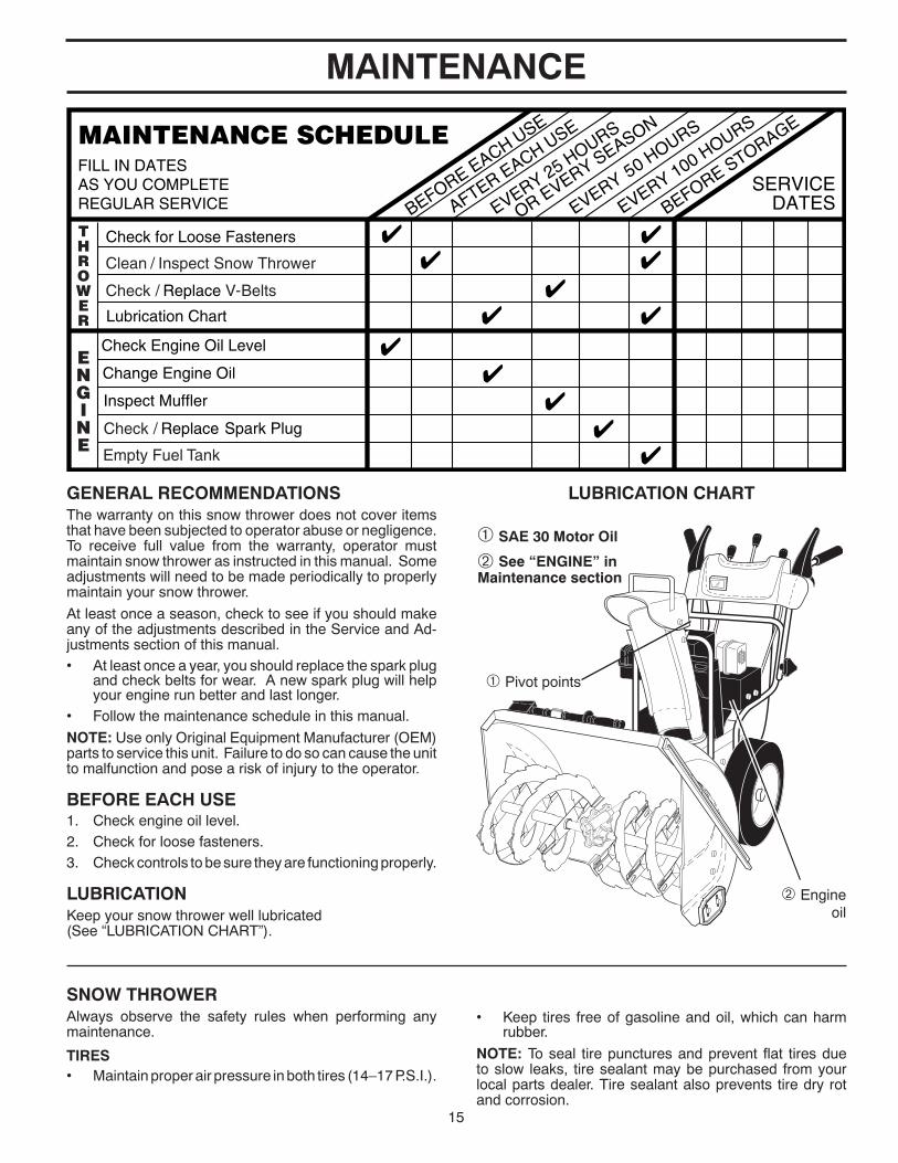
MAINTENANCE
LUBRICATION CHARTGENERAL REC OM MEN DA TIONSThe warranty on this snow thrower does not cover items that have been sub ject ed to operator abuse or negligence. To receive full value from the warranty, operator must maintain snow thrower as in struct ed in this manual. Some ad just ments will need to be made periodically to properly maintain your snow thrower.
At least once a season, check to see if you should make any of the adjustments described in the Service and Ad- just ments section of this manual.• At least once a year, you should replace the spark plug
and check belts for wear. A new spark plug will help your engine run better and last longer.
• Follow the maintenance schedule in this manual.
NOTE: Use only Original Equipment Manufacturer (OEM) parts to service this unit. Failure to do so can cause the unit to malfunction and pose a risk of injury to the operator.
BEFORE EACH USE1. Check engine oil level.2. Check for loose fasteners.3. Check controls to be sure they are functioning properly.
LUBRICATIONKeep your snow thrower well lubricated(See “LU BRI CA TION CHART”).
SNOW THROWERAlways observe the safety rules when performing any main te nance.
TIRES• Maintain proper air pressure in both tires (14–17 P.S.I.).
• Keep tires free of gasoline and oil, which can harm rubber.
NOTE: To seal tire punctures and prevent flat tires due to slow leaks, tire sealant may be purchased from your local parts dealer. Tire sealant also prevents tire dry rot and cor ro sion.
➀ SAE 30 Motor Oil
➁ See “ENGINE” inMaintenance section
➁ Engine oil
➀ Pivot points

16
MAINTENANCEBELTSCheck belts for deterioration and wear after every 50 hours of operation and replace if necessary. The belts are not ad just able. Replace belts if they begin to slip from wear. (See “TO REMOVE BELT COVER” in the Service and Adjustments section of this manual).
The belts on your snow thrower are of special con struc tion and should be replaced by original equipment man u fac tur er (OEM) belts avail able from your nearest dealer. Using other than OEM belts can cause personal injury or damage to the snow thrower.
AUGER GEAR CASE• The gear case was filled with lubricant to the proper
level at the factory. The only time the lubricant needs attention is if service has been performed on the gear case.
• If lubricant is required, use only Ronex ED #1 grease.
TRACTION DRIVE SYSTEMDO NOT lubricate the drive components inside the snow thrower. The sprockets, hex shafts, drive disc and friction wheel require no lubrication. The bearings and bushings are lifetime lubricated and require no maintenance.
CAUTION: Any lubricating of the above com po -nents can cause contamination of the friction wheel and damage to the drive system of your snow thrower.
ENGINESee engine manual.
LUBRICATIONUse only high quality detergent oil rated with API service classification SG–SL. Select the oil's SAE viscosity grade according to your expected operating temperature.
TO CHANGE ENGINE OILDetermine temperature range anticipated before next oil change. All oil must meet API service classification SG–SL.• Be sure snow thrower is on level surface.• Oil will drain more freely when warm.• Catch oil in a suitable container.
NOTE: The left side wheel may be removed from snow thrower for easier access to the oil drain plug and place- ment of a suitable container. The unit tilted, resting on the frame with the left wheel removed, will help drain any oil trapped inside the engine. (See “TO REMOVE WHEELS” in the Service and Adjustments section of this manual).1. Remove safety ignition key and disconnect spark plug
wire from spark plug and place wire where it cannot come in contact with plug.
2. Clean area around drain plug.3. Remove drain plug and drain oil in a suitable container.4. Install drain plug and tighten securely.5. Wipe off any spilled oil from snow thrower and engine.6. Install left wheel (if removed for draining oil). Be sure
to install wheel pin and retainer pin into proper hole in wheel axle (See “TO REMOVE WHEELS” in the Service and Adjustments section of this manual).
7. Remove oil fill cap/dipstick. Be careful not to allow dirt to enter the engine.
8. Refill engine with oil through oil dipstick tube. Pour slowly. Do not overfill. For approximate capacity see “PRODUCT SPECIFICATIONS” section of this man u al.
9. Use gauge on oil fill cap/dipstick for checking level. Be sure dipstick cap is tightened securely for accurate reading. Keep oil at “FULL” line on dipstick.
10. Wipe off any spilled oil.
MUFFLERInspect and replace corroded muffler as it could cre ate a fire haz ard and/or dam age.
SPARK PLUGReplace spark plug at the beginning of each season or after every 100 hours of operation, whichever occurs first. Spark plug type and gap setting are shown in the “PROD UCT SPEC I FI CA TIONS” section of this manual.
CLEANINGIMPORTANT: For best performance, keep snow thrower housing free of any dirt or trash. Clean the outside of your snow thrower after each use.
WARNING: Disconnect spark plug wire from spark plug and place wire where it can not come in contact with plug.
• Keep finished surfaces/wheels free of gasoline, oil, etc.• We do not recommend using a garden hose to clean
your snow thrower unless the electrical system, muffler and carburetor are covered to keep water out. Water in engine can result in shortened engine life.
NOTE: Although multi-viscosity oils (5W30, 10W30 etc.) improve starting in cold weather, these multi-viscosity oils will result in increased oil consumption when used above 32°F. Check your engine oil level more frequently to avoid possible engine damage from running low on oil.
Change the oil after every 25 hours of operation or at least once a year if the snow thrower is not used for 25 hours in one year.
Check the crankcase oil level before starting the engine and after each five (5) hours of continuous use. Tighten oil fill cap / dipstick securely each time you check the oil level.
17
SERVICE AND ADJUSTMENTS
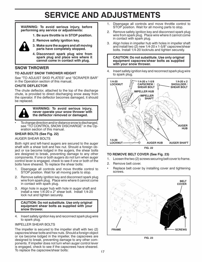
SHEAR BOLTS (See Fig. 22)AUGER SHEAR BOLTS
Both right and left-hand augers are secured to the auger shaft with a shear bolt and hex nut. Should a foreign ob-ject or ice become lodged in the augers, the shear bolts are designed to break, preventing damage to any other com po nents. If one or both augers do not turn when auger control lever is engaged, check to see if one or both of the bolts have sheared. To replace the shear bolts:1. Disengage all controls and move throttle control to
STOP position. Wait for all moving parts to stop.2. Remove safety ignition key and disconnect spark plug
wire from spark plug. Place wire where it cannot come in contact with spark plug.
3. Align hole in auger hub with hole in auger shaft and install a new 1/4-20 x 2" shear bolt. Install 1/4-20 lock nut and tighten securely.
CAUTION: Do not sub sti tute. Use only original equip ment shear bolts as sup plied with your snow thrower.
4. Insert safety ignition key and reconnect spark plug wire to spark plug.
IMPELLER SHEAR BOLTS
The impeller is secured to the impeller shaft with two (2) capscrew/shear bolts and hex nuts. Should a foreign object or ice become lodged in the impeller, the capscrews are de signed to break, preventing damage to any other com- po nents. If impeller does not turn when auger control lever is engaged, check to see if the capscrews have sheared. To replace the capscrew/shear bolts:
WARNING: To avoid serious injury, beforeperforming any service or ad just ments:
1. Be sure throttle is in STOP position.
2. Remove safety ignition key.
3. Make sure the augers and all mov ing parts have completely stopped.
4. Disconnect spark plug wire from spark plug and place wire where it can not come in contact with plug.
CHUTE DEFLECTORThe chute deflector, attached to the top of the discharge chute, is provided to direct discharging snow away from the operator. If the deflector becomes damaged, it should be re placed.
WARNING: To avoid serious injury, nev er operate your snow thrower with the deflector removed or damaged.
• To change direction and/or distance snow is dis charged, see “TO CONTROL SNOW DISCHARGE” in the Op- er a tion section of this manual.
SNOW THROWERTO ADJUST SNOW THROWER HEIGHTSee “TO ADJUST SKID PLATES” and “SCRAPER BAR” in the Operation section of this manual.
1. Disengage all controls and move throttle control to STOP position. Wait for all moving parts to stop.
2. Remove safety ignition key and disconnect spark plug wire from spark plug. Place wire where it cannot come in contact with spark plug.
3. Align holes in impeller hub with holes in impeller shaft and install two (2) new 1/4-20 x 1-5/8" capscrew/shear bolts. Install 1/4-20 locknuts and tighten securely.
CAUTION: Do not substitute. Use only original equip ment capscrew/shear bolts as sup plied with your snow thrower.
4. Insert safety ignition key and reconnect spark plug wire to spark plug.
TO REMOVE BELT COVER (See Fig. 23)1. Loosen the two (2) screws securing belt cover to frame.2. Remove belt cover.• Replace belt cover by installing cover and tightening
screws.
BELT COVER
SCREWSFRAME
FIG. 23
AUGER SHAFT
1/4-20 x 2SHOULDER /SHEAR BOLT
1/4-20 LOCK NUT
IMPELLER SHAFT
1/4-20 x 1-5/8CAPSCREW / SHEAR BOLT
1/4-20LOCKNUT
IMPELLER HUB
AUGER HUB
AUGER HUB
FIG. 22

18
SERVICE AND ADJUSTMENTS
FRAMEASSEMBLY
AUGER HOUS ING
HANDLES
8. RELIEVE TENSION ON TRACTION DRIVE BELT IDLER and remove traction drive belt from around pulleys.
HINT: Insert a 3/8" drive ratchet (in the “ON” position) into the square hole in idler arm and rotate ratchet clockwise to relieve tension.9. With tension relieved on idler, install new traction drive
belt around pulleys and inside belt keepers.10. Install clutch rod in swing plate; secure with hairpin.11. Place auger belt around and inside the groove of auger
pulley only.12. While your assistant slowly raises handles to rejoin
the auger hous ing and frame assembly, pull up on the auger belt and squeeze sides together above pulley so belt is fully seated in groove of pulley.
13. Move idler arm so it does not hit impeller pulley as you bring snow thrower completely together and check carefully for proper routing of belts. If auger belt has become dislodged from the pulley (by catching the idler arm bracket while bringing snow thrower together), separate the snow thrower and re peat step 12. Belt must be fully seated in pulley groove when bring ing the snow thrower together.
14. Install the two (2) hex bolts and tighten securely.15. INSTALL ENGINE PULLEY - Place belt in pulley groove
and slide pulley on crankshaft. Install flat washer, bolt and tighten securely (41-47 N-m torque). Make sure belt is inside belt keeper.
16. INSTALL BELT COVER and two (2) screws. Tighten securely.
17. INSTALL DISCHARGE CHUTE – See “INSTALL DIS- CHARGE CHUTE / CHUTE ROTATER HEAD” in the As sem bly / Pre-Operation section of this manual.
TO REPLACE BELTS (See Fig. 24)The auger and traction drive belts are not adjustable. If the belts are damaged or begin to slip from wear, they should be replaced. It is recommended that the belt(s) be replaced by a service center/department.
NOTE: It is recommended that both the auger and traction drive belt be replaced at the same time.
The V-belts on your snow thrower are of special con struc- tion and should be replaced by original equipment man u- fac tur er (OEM) belts avail able from your nearest service center/department. Using other than OEM belts can cause personal injury or damage to the snow thrower.
WARNING: Belt replacement requires separation of the snow thrower. While separating the auger housing from the frame assembly, it is important that an assistant stand in the operating po si tion and hold the snow thrower han dles. Serious personal injury and/or damage to the unit could occur if the snow thrower should fall during the belt chang ing process.
1. REMOVE GASOLINE FROM FUEL TANK - Drain gaso-line from fuel tank into a suitable container, out doors, away from fire or flame. Wipe up any spilled gasoline.
2. REMOVE DISCHARGE CHUTE - Loosen locknut se cur ing chute rotator head to mounting bracket only enough to allow chute rotator head to be raised and dis charge chute to be removed from snow thrower.
3. REMOVE BELT COVER - See “TO REMOVE BELT COVER” in this section of this manual.
4. REMOVE ENGINE PULLEY - Remove bolt, flat washer securing pulley to engine crankshaft. Remove outside (auger) pulley only from crank shaft.
5. SEPARATE SNOW THROWER - With your assistant standing in the operating position holding the handles, re move the two (2) bolts holding the auger housing and frame together.
WARNING: As the last bolt is removed, have your assistant carefully lower the han dles down to the ground.
6. REMOVE HAIRPIN FROM CLUTCH ROD and remove clutch rod from swing plate. Tip swing plate forward.
7. REMOVE AUGER BELT from around pulley.
FIG. 24
BELT KEEPER
IDLER ARM SQUARE
HOLE
BOLTS
TRACTION DRIVE BELT
CLUTCHING IDLER ARM BRACKET
AUGER BELT
FLAT WASHER
AUGER PULLEYAUGER
HOUSINGFRAME
ENGINEPULLEY
BOLT

19
SERVICE AND ADJUSTMENTS
TO ADJUST CABLE TENSION (See Fig. 26)Adjust cable tension by turning the adjuster turn buckle, located on the right hand cable. Grasp the long section tightly and turn the short section to lengthen the adjuster. Adjust until cable is snug.
ADJUSTER TURN BUCKLE
FIG. 26
ENGINE
SEE ENGINE MANUAL.CARBURETORYour carburetor is not adjustable. Engine performance should not be affected at altitudes up to 2,134 meters. If your engine does not operate properly due to suspected carburetor problems, take your snow thrower to a service center/department.
ENGINE SPEEDNever tamper with the engine governor, which is factory set for proper engine speed. Overspeeding the engine above the factory high speed setting can be dangerous and will void the warranty. If you think the engine-governed high speed needs adjusting, contact a service center/depart-ment, which has the proper equipment and experience to make any necessary ad just ments.
TO REMOVE WHEELS (See Fig. 25)• Remove the wheel pin and retainer pin and remove
wheel from axle.
NOTE: To seal punctures or prevent flat tires due to slow leaks, tire sealant may be purchased from your local parts dealer. Tire sealant also prevents tire dry rot and cor ro sion.
AXLE
WHEEL PIN (INSTALL IN OUTER HOLE OF AXLE ONLY)
OUTER HOLE
WHEEL HUBWHEEL
RETAINER PIN
FIG. 25
TO ADJUST TRACTION BELT AND AUGER BELT TENSIONIf the traction or auger belt is slipping because it is not tight enough when engaged, the tension can be increased by adjusting the spring location in the control rod. Unhook the rod from the control lever and move the spring at the bottom of the rod one or two holes closer to the top of the rod. This effectively shortens the rod and increases the belt tension. (See "INSTALL AUGER CONTROL ROD" in the Assembly section of this manual.)
20
STORAGEImmediately prepare your snow thrower for storage at the end of the season or if the unit will not be used for 30 days or more.
WARNING: Never store the snow thrower with gaso line in the tank in side a build ing where fumes may reach an open flame, spark or pilot light as on a fur nace, water heater, clothes dryer or gas ap pli ance. Allow the engine to cool be fore storing in any enclosure.
SNOW THROWERWhen snow thrower is to be stored for a period of time, clean it thor oughly, re move all dirt, grease, leaves, etc. Store in a clean, dry area.1. Clean entire snow thrower (See “CLEANING” in the
Main te nance section of this manual).2. Inspect and replace belts, if necessary (See “TO RE-
PLACE BELTS” in the Service and Adjustments sec tion of this manual).
3. Lubricate as shown in the Main te nance sec tion of this man u al.
4. Be sure that all nuts, bolts, screws, and pins are securely fas tened. Inspect moving parts for damage, breakage and wear. Replace if nec es sary.
5. Touch up all rusted or chipped paint surfaces; sand lightly before painting.
ENGINESee engine manual.
FUEL SYS TEMIMPORTANT: It is important to prevent gum deposits from forming in essential fuel system parts such as carburetor, fuel hose, or tank during storage. Also, alcohol blended fuels (called gasohol or using ethanol or methanol) can attract moisture which leads to separation and formation of acids during storage. Acidic gas can damage the fuel system of an engine while in storage.
• Empty the fuel tank by starting the engine and letting it run until the fuel lines and car bu re tor are empty.
• Never use engine or carburetor cleaner prod ucts in the fuel tank or permanent damage may occur.
• Use fresh fuel next season.
NOTE: Fuel stabilizer is an acceptable alternative in min- i miz ing the formation of fuel gum deposits during stor age. Add stabilizer to gasoline in fuel tank or storage container. Always follow the mix ratio found on stabilizer container. Run engine at least 10 min utes after adding stabilizer to allow the stabilizer to reach the carburetor. Do not empty the gas tank and carburetor if using fuel stabilizer.
ENGINE OILDrain oil (with engine warm) and replace with clean engine oil. (See “ENGINE” in the Maintenance section of this man ual).
CYLINDER1. Remove spark plug.2. Pour one ounce (29 ml) of oil through spark plug hole
into cylinder.3. Pull recoil starter handle slowly a few times to dis trib ute
oil.4. Replace with new spark plug.
OTHER• Remove safety ignition key; store it in a safe place. • Do not store gasoline from one season to another.• Replace your gasoline can if your can starts to rust.
Rust and/or dirt in your gasoline will cause problems.• If possible, store your snow thrower indoors and cover
it to protect it from dust and dirt.• Cover your snow thrower with a suitable pro tec tive
cover that does not retain moisture. Do not use plastic. Plastic cannot breathe, which allows con den sa tion to form and will cause your snow thrower to rust.
IMPORTANT: Never cover snow thrower while engine/ex-haust area is still warm.
21
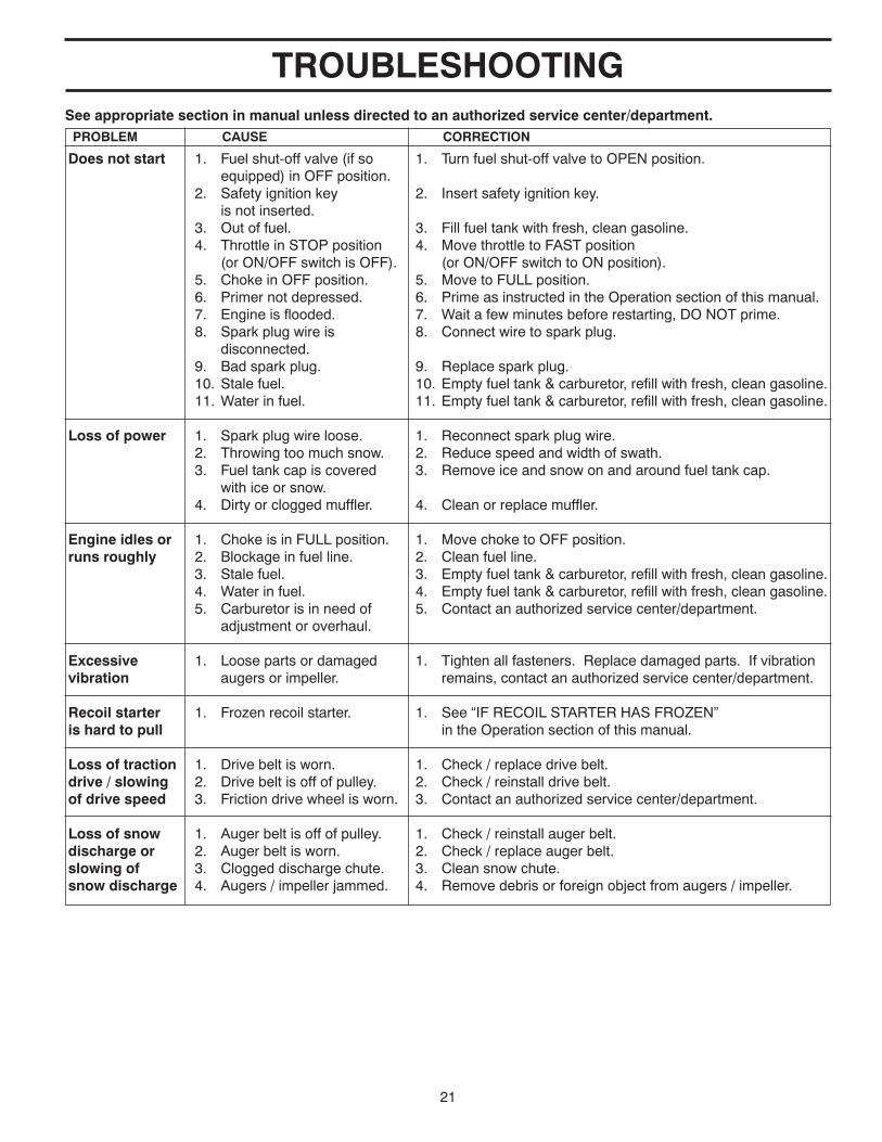
TROUBLESHOOTING
Does not start 1. Fuel shut-off valve (if so 1. Turn fuel shut-off valve to OPEN position. equipped) in OFF position. 2. Safety ignition key 2. Insert safety ignition key. is not inserted. 3. Out of fuel. 3. Fill fuel tank with fresh, clean gasoline. 4. Throttle in STOP position 4. Move throttle to FAST position (or ON/OFF switch is OFF). (or ON/OFF switch to ON position). 5. Choke in OFF position. 5. Move to FULL position. 6. Primer not depressed. 6. Prime as instructed in the Operation section of this manual. 7. Engine is flooded. 7. Wait a few minutes before restarting, DO NOT prime. 8. Spark plug wire is 8. Connect wire to spark plug. disconnected. 9. Bad spark plug. 9. Replace spark plug. 10. Stale fuel. 10. Empty fuel tank & carburetor, refill with fresh, clean gasoline. 11. Water in fuel. 11. Empty fuel tank & carburetor, refill with fresh, clean gasoline.
Loss of power 1. Spark plug wire loose. 1. Reconnect spark plug wire. 2. Throwing too much snow. 2. Reduce speed and width of swath. 3. Fuel tank cap is covered 3. Remove ice and snow on and around fuel tank cap. with ice or snow. 4. Dirty or clogged muffler. 4. Clean or replace muffler.
Engine idles or 1. Choke is in FULL position. 1. Move choke to OFF position.runs roughly 2. Blockage in fuel line. 2. Clean fuel line. 3. Stale fuel. 3. Empty fuel tank & carburetor, refill with fresh, clean gasoline. 4. Water in fuel. 4. Empty fuel tank & carburetor, refill with fresh, clean gasoline. 5. Carburetor is in need of 5. Contact an authorized service center/department. adjustment or overhaul.
Excessive 1. Loose parts or damaged 1. Tighten all fasteners. Replace damaged parts. If vibrationvibration augers or impeller. remains, contact an authorized service center/department.
Recoil starter 1. Frozen recoil starter. 1. See “IF RECOIL STARTER HAS FROZEN”is hard to pull in the Operation section of this manual. Loss of traction 1. Drive belt is worn. 1. Check / replace drive belt.drive / slowing 2. Drive belt is off of pulley. 2. Check / reinstall drive belt.of drive speed 3. Friction drive wheel is worn. 3. Contact an authorized service center/department.
Loss of snow 1. Auger belt is off of pulley. 1. Check / reinstall auger belt.discharge or 2. Auger belt is worn. 2. Check / replace auger belt.slowing of 3. Clogged discharge chute. 3. Clean snow chute.snow discharge 4. Augers / impeller jammed. 4. Remove debris or foreign object from augers / impeller.
PROBLEM CAUSE CORRECTION
See appropriate section in manual unless directed to an authorized service center/department.

22
Consumer Wheeled Products - Limited Warranty
Husqvarna warrants to the original retail purchaser that this product is free from defects in material or workmanship under normal useand maintenance from the date of retail purchase for the applicable Warranty Period shown on Exhibit A. This Limited Warranty may not be transferredto any subsequent purchaser of this product. Certain components (e.g., engines and transmissions) are excluded from coverage, and otherlimitations apply, as described in this document. Husqvarna will repair or replace at its discretion, any defective product or part covered by the LimitedWarranty, free of charge at any authorized Husqvarna Servicing Dealer/Center using original OEM Husqvarna replacement parts, subject to thelimitations and exclusions described below. Husqvarna does not offer an over-the-counter exchange program.
DISCLAIMERS, LIMITATIONS AND EXCLUSIONS
1. WARRANTY DISCLAIMER. THIS LIMITED WARRANTY IS THE SOLE EXPRESS WARRANTY PROVIDED BY HUSQVARNA AND THERE ARE NOWARRANTIES WHICH EXTEND BEYOND THE DESCRIPTION ON THE FACE HEREOF, EXCEPT AS MAY BE PROVIDED BY LAW. THIS WARRANTY ISGIVEN ONLY BY HUSQVARNA, AND MAY BE MODIFIED ONLY BY HUSQVARNA. THIS LIMITED WARRANTY IS THE FINAL EXPRESSION OF OURAGREEMENT, AND IS A COMPLETE AND EXCLUSIVE STATEMENT OF THE TERMS OF THAT AGREEMENT. THIS LIMITED WARRANTY GIVES YOUSPECIFIC LEGAL RIGHTS, AND YOU MAY ALSO HAVE OTHER RIGHTS WHICH VARY BASED ON LOCALITY
2. LIMITED DURATION. ANY WARRANTY THAT MAY BE IMPLIED BY LAW (INCLUDING ANY IMPLIED WARRANTY OF FITNESS FOR APARTICULAR PURPOSE OR USE AND IMPLIED WARRANTY OF MERCHANTABILITY) IS LIMITED TO THE DURATION OF THE APPLICABLEWARRANTY PERIOD UNDER THIS LIMITED WARRANTY. SOME LOCALITIES DO NOT ALLOW LIMITATIONS ON HOW LONG AN IMPLIEDWARRANTY LASTS, SO THE ABOVE LIMITATIONS MAY NOT APPLY TO YOU.
3. EXCLUSIVE REMEDIES. SOME LOCALITIES, INCLUDING THE PROVINCE OF QUEBEC, DO NOT ALLOW THE EXCLUSION OR LIMITATION OFLIABILITY FOR INJURY TO PERSON OR FOR DAMAGES RESULTING FROM THE FAULT OF THE MANUFACTURER AND/OR THE EXCLUSION ORLIMITATION OF INCIDENTAL OR CONSEQUENTIAL DAMAGES. AS SUCH, SOME OF THE FOLLOWING LIMITATIONS MAY NOT APPLY TO YOU. THEABOVE REMEDIES ARE THE EXCLUSIVE REMEDIES FOR ANY BREACH OF THIS LIMITED WARRANTY. NO OTHER REMEDY, INCLUDING, BUT NOTLIMITED TO ANY SPECIAL, INCIDENTAL, INDIRECT OR CONSEQUENTIAL DAMAGES, FOR LOST PROFITS, LOST SALES, INJURY TO PERSON ORPROPERTY, OR ANY OTHER INCIDENTAL OR CONSEQUENTIAL LOSS SHALL BE AVAILABLE, AND ALL SUCH DAMAGES ARE HEREBYDISCLAIMED.
4. Engines, Transmissions and certain other components are NOT covered. This Limited Warranty does not cover any of the following:
(a) Engines and Attachments.Except where otherwise indicated on Exhibit A, all Engines and Attachments are not covered by this Limited Warranty. In most cases, theseitems are NOT manufactured by Husqvarna in which case they may be covered separately by their respective manufacturer's warranties if one is provided and included withthe product at the time of purchase. All such claims must be submitted and sent to the appropriate manufacturer or as otherwise directed in those separate warranties.Husqvarna is not authorized to handle warranty adjustments or repairs on engines manufactured by Briggs & Stratton, Honda, Kawasaki, or Kohler (with the exception ofmodels equipped with LCT engines). Husqvarna does not assume any warranty obligation of the other manufacturers' engines under this Limited Warranty.
(b) Transmissions. Except where otherwise indicated on ExhibitA, Transmission / Transaxle (including Drive Systems) are not covered by this Limited Warranty. In mostcases, these items are NOT manufactured by Husqvarna in which case they may be covered separately by their respective manufacturer's warranties if one is provided andincluded with the product at the time of purchase. The following transmission / transaxle manufacturers, Dana, Hydro-Gear, Tuff-Torq provide a warranty for thetransmission / transaxle to the ultimate purchaser or to Husqvarna. Husqvarna will assign the transmission / transaxle manufacturer's warranty or any rights thereof to theoriginal purchaser of the unit. To obtain transmission / transaxle warranty service, first contact the retailer who you purchased the unit from. Should you require assistanceor have any questions concerning transmission / transaxle warranty coverage, contact Husqvarna directly at our website www.husqvarna.com or call 800-487-5951 (US) or800-805-5523 (Canada) for an authorized Husqvarna service provider. All such claims must be submitted and sent to the appropriate manufacturer or as otherwise directedin those separate warranties. Husqvarna is not authorized to handle warranty adjustments or repairs on transmissions or transaxles. Husqvarna does not assume anyobligations under this Limited Warranty for the above listed manufacturers (for exceptions - see Exhibit A).
(c) Expendable Parts. This Limited Warranty does not cover general maintenance parts and items ("Expendable Parts"), including without limitation spark plugs, bulbs,filters, lubricants, starter cords, belts, blades, and blade adapters.
(d) Emissions Control Components. This Limited Warranty does not cover Emissions control equipment and components to the extent regulated by the U.S. EnvironmentalProtection Agency or similar state, provincial or federal agencies. Such equipment and components are covered by a separate emission control warranty statement suppliedwith your new product. Please consult this separate warranty statement for details.
5. Any COMMERCIAL, INSTITUTIONAL, AGRICULTURAL, INDUSTRIAL, INCOME PRODUCING, or RENTAL use will result in eitherNo Warranty or a Shortened Warranty Period. Depending on the product, there is either NO WARRANTY (whether statutory, contractual orotherwise) or a reduced warranty if the product is used for commercial, institutional, agricultural, industrial, income producing, or rental purposes and, insuch circumstances, this Limited Warranty is offered instead of and replaces any warranty regime provided for by law. Please refer to Exhibit A.
6. Reconditioned or Refurbished Products have a 30 Day Limited Warranty. Under this Limited Warranty, Certified Factory Reconditioned orRefurbished products have a 30 Day Limited Warranty for parts and labor for Non-Commercial Use. Products are only reconditioned at the HusqvarnaFactory.
7. Owner's (Your) Responsibilities. To preserve your rights under this Limited Warranty, you must exercise reasonable care and use of the product,including, following the preventative maintenance, storage, fuel and oil usages as prescribed in the enclosed operator's manual. For example, thefollowing items are the Owner's responsibility and are not covered by this Limited Warranty:
a. Set-up and pre-delivery service, and engine tune-ups;
b. Adjustments after the first (30) thirty days of purchase and beyond, such as throttle cable, belt guides adjustments; and
c. Preventative maintenance as outlined in the operator's manual.
In addition, you must cease using the product immediately upon any failure or damage. The product should be taken to an authorized Husqvarnaservicing dealer prior to any further use.
8. Damages resulting from normal aging, wear and tear or neglect are NOT covered. The Limited Warranty does not cover damage other thanthat resulting from defects in material or workmanship. The following are NOT considered defects in material or workmanship, and therefore are NOTcovered.
23
(a) Abrasion to mower decks;
(b) Tires damaged by external punctures;
(c) Natural discoloration of materials due to ultraviolet light;
(d) Damage to cutting equipment by way of contact with, rocks, or other non-approved materials and/or structures;
In addition, this Limited Warranty does not cover damages, malfunctions or failures resulting from abuse or neglect of the product related to or includingany of the following:
(e) Failure to provide or perform required maintenance services as prescribed in the operator's manual;
(f) Abuse, misuse, neglect, modifications, alterations, normal wear, improper servicing, use of unauthorized attachments, Lack of lubrication or
engine failure, due to the use of oils that do not meet Engine manufacturer's specifications;
(g) Use of gasohol, containing methanol (wood alcohol). Gasohol which contains a maximum 10% ethanol (grain alcohol) or 15% MTBE
(methyl/tertiary/butyl/ether) is approved;
(h) Use of ether or any starting fluids;
(i) Pressure cleaning or steam cleaning the product;
(j) Use of spark plugs other than those meeting emission performance requirements listed in the operator's manual;
(k) Tampering with engine speed governor or emission components, or running engines above specified and recommended engine speeds as
listed in your operator's manual;
(l) Operation of the unit with improperly installed/removed or modified cutting shields, guards, or safety devices;
(m) Any removed/damaged air filter, excessive dirt, abrasives, salt water, moisture, corrosion, rust, varnish, stale fuel, or any adverse reaction due
to incorrect storage procedures;
(n) Failures due to improper set up, pre-delivery service or repair service by anyone other than an authorized Husqvarna servicing dealer during
the warranty period;
(o) Dirt contaminated grease or oil, use of incorrect type of greases or oils, failure to comply with recommended greasing intervals, water or
moisture damage, and/or improper storage;
(p) Sprayers pumping or spraying caustic or flammable materials, lack of or broken strainers; or
(q) Continued use of product, after initial operational problem or failure occurs.
9. Reinforced Stamped (Armor Protected) 10 Year Limited & Fabricated Limited Lifetime, Deck Warranties. These Limited Warranties are forthe deck shell only mechanical components/parts such as belts, pulleys, spindle housings, bearings, blades, rods, height adjusters, caster/anti scalpwheels are NOT covered. The Limited Lifetime Warranty does not cover damage other than that resulting from defects in material orworkmanship. The following are NOT considered defects in material or workmanship, and therefore are NOT covered:
(a) Abrasion to mower decks, including sand wear;
(b) Damage to cutting equipment by way of contact with, rocks, or other non-approved materials and/or structures;
(c) Rust and corrosion; and
(d) Natural discoloration of paint or other materials due to ultraviolet light.
HOW TO OBTAIN SERVICE
10. Authorized Husqvarna Servicing Dealer/Center. In order to obtain warranty coverage it is your responsibility (at your expense) to deliver or shipyour Husqvarna unit to an authorized Husqvarna Servicing Dealer/Center and arrange for pick-up or return of your unit after the repairs have been made.If you do not know the location of your nearest authorized Husqvarna Servicing Dealer, call Husqvarna, at 1-800-487-5951 during the hours of 8:00 AMto 8:00 PM Eastern Standard Time, or visit www.husqvarna.com. Should you require assistance or have questions concerning this Limited Warranty, youmay contact us at 800-487-5951 (US) or 800-805-5523 (Canada) during the hours of 8:00 AM to 8:00 PM Eastern Standard Time or contact us throughthe web at www.husqvarna.com.
11. Documentation Required. You must maintain and present Proof of purchase (including date, product model and, if applicable, engine serialnumber) to an authorized Husqvarna Servicing Dealer for warranty service under this Limited Warranty. Proof of purchase rests solely with you.Husqvarna encourages you to register your product online at www.usa.husqvarna.com (US & Canada) to help ensure, among other things, that you canbe notified of important product information. However, registering your product is not a condition of warranty service.
Husqvarna Professional Products, NA, Inc.
9335 Harris Corners Parkway, Suite 500, Charlotte, NC28269
575 49 43-01 W 2012 IR

24
Consumer Wheeled Limited Warranty Chart 2012 Exhibit AConsumer (personal,
household use only)Commercial (any commercial,
professional, institutional, agricultural, or income producing use, other than
Rental Use)
Rental (anyrental usage)
Riding Lawn Tractors:Frame, Chassis, Front Axle 5 Years No Warranty No WarrantyEngine* * * *Transmission (if made by Husqvarna/Peerless) 3 Years No Warranty No WarrantyTransmission (if third party)** ** ** **XLS Models only - stamped deck shell. Armor Protected Limited Warranty 10 Years No Warranty No WarrantyFabricated Deck shell. Limited Lifetime Warranty *** No Warranty No WarrantyBattery 1 Year Pro-rated No Warranty No WarrantyOther Non-Expendable Components 3 Years No Warranty No Warranty
Engine* * * *Transmission ** ** No Warranty No Warranty
RZ4623 (967009801 & 967009802)RZ5426 (967003601 & 967003602) - stamped deck shell. Armor Protected Limited Warranty 10 Years No Warranty No WarrantyFabricated Deck shell. Limited Lifetime Warranty *** No Warranty No WarrantyBattery 1 Year Pro-rated No Warranty No WarrantyOther Non-Expendable Components 3 Years No Warranty No Warranty
Engine* * * *Transmission ** ** ** **MZ5424S & MZ5425S (967003901 & 25021) - stamped deck shell. Armor Protected Limited Warranty 10 Years No Warranty No Warranty
Fabricated Deck shell. Limited Lifetime Warranty *** No Warranty No WarrantyBattery 1 Year Pro-rated No Warranty No WarrantyOther Non-Expendable Components 3 Years 1 Year No Warranty
LE475 Edger, Tillers, Snow ThrowersEngine* * * *Other Non-Expendable Components 2 Years 90 days 90 daysTiller Tines *** No Warranty No Warranty
Walk Behind Mowers, High Wheel TrimmerEngine* * * *Battery 1 Year Pro-rated No Warranty No WarrantyOther Non-Expendable Components 3 Years No Warranty No Warranty
Hovering TrimmersEngine* * * *Other Non-Expendable Components 2 Years 1 Year 90 days
Front Mounted Deck RidersEngine* * * *Transmission 2 Years No Warranty No WarrantyOther Non-Expendable Components 2 Years No Warranty No Warranty
CultivatorsBattery 1 Year Pro-rated No Warranty No WarrantyOther Non-Expendable Components 2 Years No Warranty No Warranty
Pressure WashersModel 5525PW: Engine* * * * Pump 2 Years No Warranty No Warranty Other Non-Expendable Components 2 Years No Warranty No Warranty
Engine* * * * Pump 2 Years 2 Years No Warranty Other Non-Expendable Components 2 Years 2 Years No Warranty
GeneratorsEngine* * * *
Other Non-Expendable Components**2 Years (2nd Year Parts
Only) *2 Years-1365GN (2nd Year Parts Only) No WarrantySpreaders
Residential Zero Turn Mowers ( MZ & EZ )
All other Pressure Washers (6027PW, 9032PW, 1340PW)
Product/Component
Residential Zero Turn Mowers ( RZ Only )

25
Consumer Wheeled Limited Warranty Chart 2012 Exhibit AConsumer (personal,
household use only)Commercial (any commercial,
professional, institutional, agricultural, or income producing use, other than
Rental Use)
Rental (anyrental usage)
Product/ComponentSpreader 1 Year 1 Year 1 Year
Robotic MowersRobotic Mower 2 Years 90 days 90 daysBattery 1 Year 1 Year 1 Year
Parts & Accessories (if purchased)Accessories (e.g., grass catcher, bumper guard accessories, etc. 1 Year No Warranty No WarrantyParts (e.g., belts, blades, etc.) 30 days No Warranty No Warranty
Parts & Accessories (if replaced in Warranty Service)Replacement parts and/or accessories provided under this Limited Warranty are warranted only for the BALANCE of the warranty period applicable to the part or accessory that was replaced. See to left See to left See to left
Consumer Commercial Rental
Armor Protected Stamped Deck Shell Example Below Fabricated Deck Shell Example Below
Stamped Deck Shell below, NOT reinforced
*** "Limited Lifetime Warranty" on Tiller tines and Fabricated Deck shell is for the life of the product or 7 (seven) years after the last date of the complete unit's final production, whichever comes first. Deck Shell replacement will be limited to a maximum of two (2) decks within the Limited Lifetime Warranty.
** See reference 1 (b) of the warranty statement.RZ - Two (2) Year Consumer warranty, parts & labor, with Hydro-Gear Distributor network.EZ - One (1) Year Commercial warranty, parts & labor, with Husqvarna. Two (2) Year Consumer warranty, parts & labor, with Hydro-Gear Distributor network.MZ - Two (2) Year Commercial warranty, parts & labor, with Hydro-Gear Distributor network.
* See Separate Engine Manufacturer's or Manufacturer's warranty. LCT Engines on specific Snow Throwers & Tillers, warranty throughHusqvarna.
Armor Protected Stamped Deck Shell
Reinforced area
No reinforced area

26
SERVICE NOTES

27
SERVICE NOTES

08/03/2012 SR
Related Documents