Precision Drilling Machines Tapping Machines Multi Head Drills Tool Grinders Tool Post Grinders Machine Vices Special Production Equipment Accessories Riveting Machines Pedestal Grinders Metal Cutting Saws Linishers YOUR BROBO DISTRIBUTOR IS: PRODUCT AND MAINTENANCE MANUAL OHS SERIES METAL SAWS MODEL No. S315A, S350D, S400B & SCV350 – 400 / Serial No’s. C 29680~ BROBO GROUP (AUST) PTY. LTD. A.C.N. 098 264 316 A.B.N. 42 098 264 316 8 Fowler Rd, Dandenong, 3175 PO BOX 4274 Dandenong Sth, 3164 Victoria, AUSTRALIA. Tel: 61 3 9794 8751 Email: [email protected] Fax: 61 3 9794 8792 Website: www.brobo.com.au Quality Endorsed Company ISO 9001 Lic. 10292 SAI GLOBAL Quality System Bench Mount Unit Floor Mount Unit

Welcome message from author
This document is posted to help you gain knowledge. Please leave a comment to let me know what you think about it! Share it to your friends and learn new things together.
Transcript


2
OPERATING MANUAL FOR BROBO GROUP MANUAL METAL CUTTING SAWS TECHNICAL SPECIFICATION 3 CHAPTER 1: Installation of the Machine
1.1 Unpacking and Handling the Machine 6 1.2 Parts Checklist 7 1.3 Minimum Requirements 7 1.4 Anchoring the Saw 8
1.5 Connection to Power Source 9 CHAPTER 2: Safety and Accident Prevention
2.1 Operation of the Machine 10 2.1.1 Noise Level 11 2.1.2 Power Supply 11 2.2 General Requirements 11 2.3 Advice for the Operator 12 2.4 Machine Safety Devices 14 2.4.1 Reference Standards 14
CHAPTER 3: Main Functions and Operation of the Machine 3.1.1 Cutting Head 15 3.1.2 Saw Safety Guard 15 3.1.3 Saw Handle (with ‘Dead Man’ Trigger Switch) 16 3.1.4 Main power standby & Speed selector switch 16 3.1.5 Manual Vice Clamp 16 3.2 Preparation for Operation 17 3.3 Operation Recommendations 18
CHAPTER 4: Drawings, Layouts, Assembly and Spare Parts
4.1.1 Assembly Drawing (1 of 3) 19 4.1.2 Assembly Drawing (2 of 3) 20 4.1.3 Assembly Drawing (3 of 3) 22
4.2.1 Electrical Circuit 1PH/ 3PH & 3PH Dual Speed Circuit Diagram 23 4.2.2 Electrical Circuit 3PH with Dead Man Trigger (DMT) 24 4.3 Component Layout & Electrical Schematic Drawings (3PH) 25
4.4 Standard Saw Gearbox Assembly 26 4.5 Standard Manual Vice Assembly 27 4.6 Dual Manual Vice Assembly 28
CHAPTER 5: Adjustments for the Saw Unit
5.1 Changing the Blade 29 5.2 Adjusting the Cutting Angle 30 5.3 Cutting and Feeding Speeds 30 5.4 Refilling the Lubricator 30 5.5 Adjusting the Brobolube Unit 31 5.5.1 Lubricating Oil Precautions – Health Hazard Information 31
CHAPTER 6: Maintenance and Selection of Consumables
6.1 Role of the Operator 32 6.2 Maintenance Requirements 32 6.3 General Maintenance of Functioning Components 32
CHAPTER 7: Troubleshoot
7.1 Troubleshooting For Blade and Cutting Problems 34 7.2 General Troubleshooting 36
APPENDIX i. Hazard/Risk Assessment 37
3
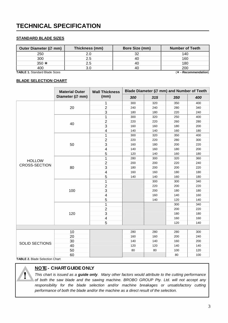
TECHNICAL SPECIFICATION
STANDARD BLADE SIZES
Outer Diameter (∅ mm) Thickness (mm) Bore Size (mm) Number of Teeth 250 2.0 32 140 300 2.5 40 160 350 2.5 40 180 400 3.0 40 200
TABLE 1. Standard Blade Sizes ( - Recommendation) BLADE SELECTION CHART
Material Outer Diameter (∅ mm)
Wall Thickness (mm)
Blade Diameter (∅ mm) and Number of Teeth 300 315 350 400
HOLLOW CROSS-SECTION
20 1 300 320 350 400 2 240 240 280 340 3 180 180 220 240
40
1 300 320 250 400 2 220 220 260 280 3 160 160 180 200 4 140 140 160 180
50
1 300 320 350 400 2 220 220 280 300 3 160 180 200 220 4 140 160 180 200 5 120 140 160 180
80
1 280 300 320 360 2 200 200 220 240 3 180 200 200 220 4 160 160 180 180 5 140 140 160 180
100
1
300 300 340 2 220 200 220 3 200 180 180 4 160 140 160 5 140 120 140
120
1
300 340 2 200 220 3 180 180 4 160 160 5 120 140
SOLID SECTIONS
10
280 280 280 300 20 160 160 200 240 30 140 140 160 200 40 120 120 140 140 50 80 80 100 120 60 80 100
TABLE 2. Blade Selection Chart
NOTE - CHART GUIDE ONLY
This chart is issued as a guide only. Many other factors would attribute to the cutting performance of both the saw blade and the sawing machine. BROBO GROUP Pty. Ltd. will not accept any responsibility for the blade selection and/or machine breakages or unsatisfactory cutting performance of both the blade and/or the machine as a direct result of the selection.
!
4
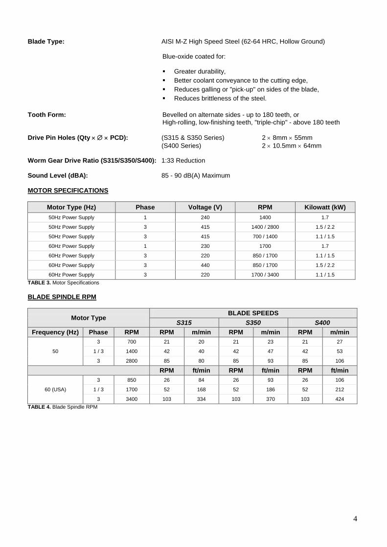
Blade Type: AISI M-Z High Speed Steel (62-64 HRC, Hollow Ground)
Blue-oxide coated for:
Greater durability, Better coolant conveyance to the cutting edge, Reduces galling or "pick-up" on sides of the blade, Reduces brittleness of the steel.
Tooth Form: Bevelled on alternate sides - up to 180 teeth, or High-rolling, low-finishing teeth, "triple-chip" - above 180 teeth Drive Pin Holes (Qty × ∅ × PCD): (S315 & S350 Series) 2 × 8mm × 55mm (S400 Series) 2 × 10.5mm × 64mm Worm Gear Drive Ratio (S315/S350/S400): 1:33 Reduction Sound Level (dBA): 85 - 90 dB(A) Maximum MOTOR SPECIFICATIONS
Motor Type (Hz) Phase Voltage (V) RPM Kilowatt (kW) 50Hz Power Supply 1 240 1400 1.7
50Hz Power Supply 3 415 1400 / 2800 1.5 / 2.2
50Hz Power Supply 3 415 700 / 1400 1.1 / 1.5
60Hz Power Supply 1 230 1700 1.7
60Hz Power Supply 3 220 850 / 1700 1.1 / 1.5
60Hz Power Supply 3 440 850 / 1700 1.5 / 2.2
60Hz Power Supply 3 220 1700 / 3400 1.1 / 1.5 TABLE 3. Motor Specifications BLADE SPINDLE RPM
Motor Type BLADE SPEEDS
S315 S350 S400 Frequency (Hz) Phase RPM RPM m/min RPM m/min RPM m/min
50
3 700 21 20 21 23 21 27
1 / 3 1400 42 40 42 47 42 53
3 2800 85 80 85 93 85 106
RPM ft/min RPM ft/min RPM ft/min
60 (USA)
3 850 26 84 26 93 26 106
1 / 3 1700 52 168 52 186 52 212
3 3400 103 334 103 370 103 424 TABLE 4. Blade Spindle RPM
5
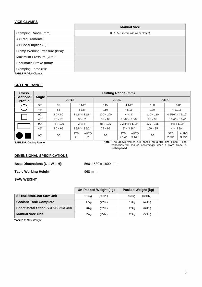
VICE CLAMPS Manual Vice
Clamping Range (mm) 0 - 135 (145mm w/o wear plates)
Air Requirements:
Air Consumption (L):
Clamp Working Pressure (kPa):
Maximum Pressure (kPa):
Pneumatic Stroke (mm):
Clamping Force (N): TABLE 5. Vice Clamps CUTTING RANGE
Cross Sectional
Profile Angle
Cutting Range (mm)
S315 S350 S400 90° 90 3 1/2” 115 4 1/2” 130 5 1/8”
45° 85 3 3/8” 110 4 5/16” 120 4 11/16”
90° 80 × 80 3 1/8” × 3 1/8” 100 × 100 4” × 4” 110 × 110 4 5/16” × 4 5/16”
45° 75 × 75 3” × 3” 85 × 85 3 3/8” × 3 3/8” 95 × 95 3 3/4” × 3 3/4”
90° 75 × 100 3” × 4” 85 × 135 3 3/8” × 5 5/16” 100 × 135 4” × 5 5/16”
45° 80 × 65 3 1/8” × 2 1/2” 75 × 95 3” × 3 3/4” 100 × 95 4” × 3 3/4”
90° 50
STD 2”
AUTO 3”
60 STD 2 3/4”
AUTO 3 1/2”
60 STD 2 3/4”
AUTO 3 1/2”
Note: The above values are based on a full size blade. The capacities will reduce accordingly when a worn blade is resharpened.
DIMENSIONAL SPECIFICATIONS Base Dimensions (L × W × H): 560 × 530 × 1800 mm Table Working Height: 968 mm SAW WEIGHT Un-Packed Weight (kg) Packed Weight (kg)
S315/S350/S400 Saw Unit 136kg (300lb.) 150kg (330lb.)
Coolant Tank Complete 17kg (42lb.) 17kg (42lb.)
Sheet Metal Stand S315/S350/S400 28kg (62lb.) 28kg (62lb.)
Manual Vice Unit 25kg (55lb.) 25kg (55lb.)
TABLE 6. Cutting Range
TABLE 7. Saw Weight
6
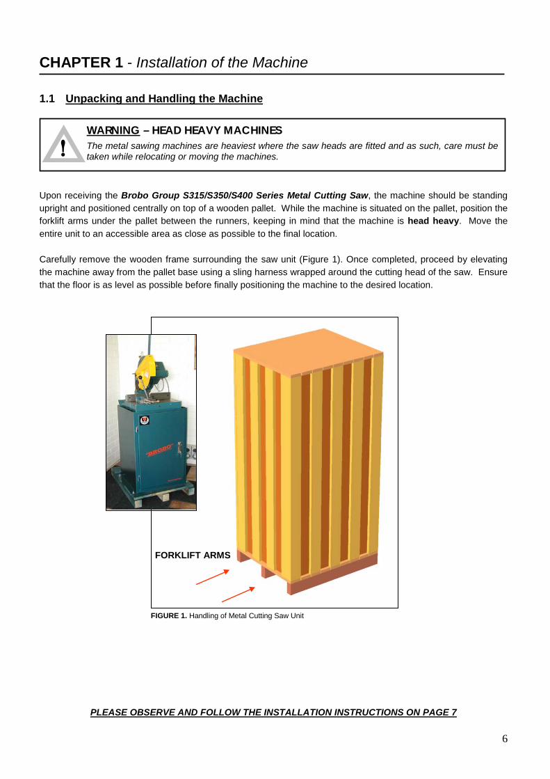
WARNING – HEAD HEAVY MACHINES
The metal sawing machines are heaviest where the saw heads are fitted and as such, care must be taken while relocating or moving the machines. !
CHAPTER 1 - Installation of the Machine 1.1 Unpacking and Handling the Machine Upon receiving the Brobo Group S315/S350/S400 Series Metal Cutting Saw, the machine should be standing upright and positioned centrally on top of a wooden pallet. While the machine is situated on the pallet, position the forklift arms under the pallet between the runners, keeping in mind that the machine is head heavy. Move the entire unit to an accessible area as close as possible to the final location. Carefully remove the wooden frame surrounding the saw unit (Figure 1). Once completed, proceed by elevating the machine away from the pallet base using a sling harness wrapped around the cutting head of the saw. Ensure that the floor is as level as possible before finally positioning the machine to the desired location. FIGURE 1. Handling of Metal Cutting Saw Unit
PLEASE OBSERVE AND FOLLOW THE INSTALLATION INSTRUCTIONS ON PAGE 7
FORKLIFT ARMS
7
WARNING – OPERATING VOLTAGE VARIATION
Each saw model has an inbuilt safety system to protect it against voltage variations. However, for the machine to perform efficiently, ensure that the saw unit operates within ±10% limits of the recommended voltage of the motor.
!
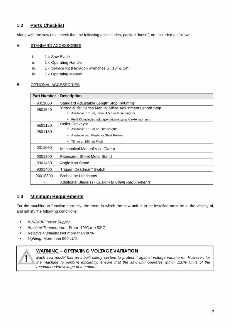
1.2 Parts Checklist Along with the saw unit, check that the following accessories, packed "loose", are included as follows: A. STANDARD ACCESSORIES
i. 1 × Saw Blade ii. 1 × Operating Handle iii. 1 × Service Kit (Hexagon wrenches 5”, 10” & 14”) iv. 1 × Operating Manual
B. OPTIONAL ACCESSORIES
Part Number Description
9311060 Standard Adjustable Length Stop (600mm) 9501540 ‘Brobo-Rule’ Series Manual Micro-Adjustment Length Stop
Available in 1.5m, 3.0m, 4.5m or 6.0m lengths
Field Kit includes rail, tape, micro-stop and extension arm.
9501120 9501180
Roller Conveyor Available in 1.5m or 3.0m lengths
Available with Plastic or Steel Rollers
75mm or 150mm Pitch
9311060 Mechanical Manual Vice Clamp
9301300 Fabricated Sheet Metal Stand 9301450 Angle Iron Stand 9301400 Trigger ‘Deadman” Switch 93018800 Brobolube Lubricants
- Additional Blade(s) - Custom to Client Requirements 1.3 Minimum Requirements For the machine to function correctly, the room in which the saw unit is to be installed must be in the vicinity of, and satisfy the following conditions: 415/240V Power Supply Ambient Temperature - From -10°C to +50°C. Relative Humidity: Not more than 90%. Lighting: More than 500 LUX.
8
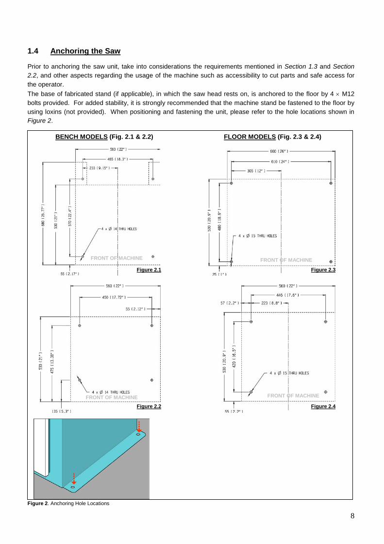
1.4 Anchoring the Saw Prior to anchoring the saw unit, take into considerations the requirements mentioned in Section 1.3 and Section 2.2, and other aspects regarding the usage of the machine such as accessibility to cut parts and safe access for the operator. The base of fabricated stand (if applicable), in which the saw head rests on, is anchored to the floor by 4 × M12 bolts provided. For added stability, it is strongly recommended that the machine stand be fastened to the floor by using loxins (not provided). When positioning and fastening the unit, please refer to the hole locations shown in Figure 2. Figure 2. Anchoring Hole Locations
FRONT OF MACHINE FRONT OF MACHINE
FRONT OF MACHINE FRONT OF MACHINE
BENCH MODELS (Fig. 2.1 & 2.2) FLOOR MODELS (Fig. 2.3 & 2.4)
Figure 2.1 Figure 2.3
Figure 2.2 Figure 2.4

9
VOLTAGE MAIN VOLTAGE 415/240V 1/ 3 PH 240V
1.5 Connection to Power Source Before connecting the machine to the power supply, check that the socket is not connected in series with other machines. This condition is critical for the ideal operation of the saw unit. (Refer to Figure 4 for wiring of “4-CORE” power supply cable from the machine to a power plug. Note that single-phase machines are supplied in Australia with 15-amp plug).
Figure 4. Connection for “4-CORE” Wire System with Neutral Single and Three Phase
i. Single phase machines are provided with three pins, 15 amps rated plugs and leads for connection to 240V, 50Hz power supply in Australia.
ii. Three phase machines should be fitted with a suitable, approved four pin plugs (ie. three phase and
earthing - not provided)
iii. Check the power supplied and motor specifications before plugging in the machine. Check terminal connection on dual voltage motor terminal box and connect it accordingly to the corresponding voltage supply.
iv. If dual motor is requested, the motor is always connected to the higher voltage, unless otherwise
specified prior to order being placed. To connect the machine to the power supply, proceed as follows:
1) Insert the power plug into the socket, while ensuring that the mains voltage is compatible for which the saw unit is operating at.
2) Switch the saw on by rotating the control switch located on the saw head assembly as shown in Figure 5
below.
10
Figure 5. Main Control Switch 3) Check that the motor is operating in the correct direction, that is the blade is rotating downwards and into
the direction of the vice clamps. 4) Ensure that all electrical leads and cables (including supply leads) are maintained in a good condition and
away from sharp objects. All leads should be replaced if cut, sliced or damaged in any way. Brobo Group S315/S350/S400 Series Metal Cutting Saw is now ready for use. Chapter 3 provides a detailed description of the various features of the saw and its operating cycles.
CHAPTER 2 - Safety and Accident Prevention The Brobo Group S315/S350/S400 Series Metal Cutting Saw has been designed and manufactured in accordance to Australian Standards. It is HIGHLY RECOMMENDED that the instructions and warnings contained in this chapter be carefully followed for correct usage of the machine. 2.1 Operation of the Machine The BW S315/S350/S400 Series Metal Cutting Saw is specifically design to cut ferrous and non-ferrous metal cross sections with solid or thin-walled profiles. Other types of material and machining are not compatible for use with the specifications of the saw. This machine involves a high-speed blade rotation; therefore extreme caution is required when operating the device. The employer is responsible for instructing the personnel who, in turn, are obliged to inform the operator of any accident risks, safety devices, noise emission and accident prevention regulations provided for by national and international laws governing the use of the machine. The operator must be fully aware of the position and functions of all the machine’s controls. All those concerned must strictly adhere to ALL instructions, warnings and accident prevention standards in this manual. The following definitions are those provided for by the EEC DIRECTIVE ON MACHINERY No. 98/37/CE: Danger Zone - any zone in and/or around a machine in which the presence of a person constitutes a risk
for the safety and health of that person. Person Exposed - any person finding him or herself, either completely or partly in a danger zone.
Operator - the person or persons given the responsibility of installing, operating, adjusting, maintaining,
cleaning, repairing, and transporting the machine.
WARNING – UNAUTHORISED MODIFICATIONS/REPLACEMENTS/USE
The manufacturer declines any responsibility whatsoever, either civil of criminal, in the case of unauthorised interference or replacement of one or more parts or assemblies on the machine, or if accessories, tools and consumable materials used are different from those recommended by the manufacturer, or if the machine is inserted in a plant system and its proper function is altered.
!
5
11
2.1.1 Noise Level The noise level of an idling metal saw, fitted with a 180-tooth blade (supplied as standard by Brobo Group) has been measured to be below 85 dBA. This complies with the Australian Occupational Health and Safety (Noise) Regulations 1992.
Please note that peak impulse noise levels will be experienced due to variables including blade characteristics, type, and condition. This will also vary accordingly depending on the size and type of sample being cut. Under these circumstances, management should make available to the operator(s) the appropriate hearing protection equipment as prescribed under the above stated act. 2.1.2 Power Supply The 415/240V power supply requirements for this machine are of a high level and unauthorised interference and or inadequate maintenance could result in a situation that could put the operator at risk. A qualified electrical engineer should always be assigned to maintain and repair the system. 2.1.3 Compressed Air Supply
Various functions of the saw are carried out via the use of 6kPa compressed air. During these operations, situations would arise where machine parts and materials are clamped together and would potentially pose a serious safety issue to an inexperienced operator. Operators should be thoroughly instructed about these hazards. Only a qualified electrician should carry out regular maintenance of this system. 2.2 General Requirements Lighting Insufficient lighting during the operation of the saw unit would constitute a safety hazard for the people concerned. For this reason, the user of the machine must provide adequate lighting in the working area to eliminate areas in shadow, whilst also preventing dazzling illumination sources (reference standard ISO 8995 - 2002 ‘Lighting of Indoor Workplaces’). Connection Check that the power supply cables, compressed air supply (if applicable) and coolant system complies with, and are operating within the acceptable range of the saw capabilities. Faulty, damaged or worn components must be replaced immediately. Earthing Systems The installation of the earthing system must comply with the requirements stated in the IEC Standards Part 195: Earthing and Protection Against Electric Shocks 1998.
12
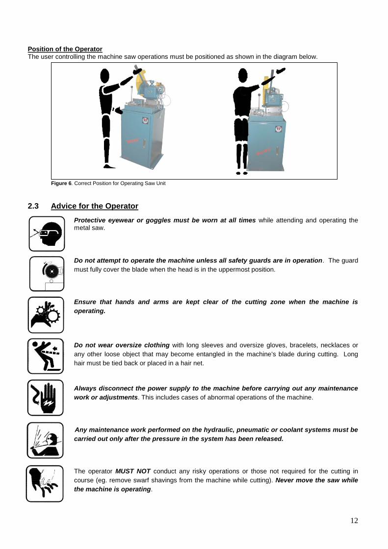
Position of the Operator The user controlling the machine saw operations must be positioned as shown in the diagram below. Figure 6. Correct Position for Operating Saw Unit 2.3 Advice for the Operator
Protective eyewear or goggles must be worn at all times while attending and operating the metal saw.
Do not attempt to operate the machine unless all safety guards are in operation. The guard
must fully cover the blade when the head is in the uppermost position.
Ensure that hands and arms are kept clear of the cutting zone when the machine is operating.
Do not wear oversize clothing with long sleeves and oversize gloves, bracelets, necklaces or any other loose object that may become entangled in the machine’s blade during cutting. Long hair must be tied back or placed in a hair net.
Always disconnect the power supply to the machine before carrying out any maintenance
work or adjustments. This includes cases of abnormal operations of the machine.
Any maintenance work performed on the hydraulic, pneumatic or coolant systems must be carried out only after the pressure in the system has been released.
The operator MUST NOT conduct any risky operations or those not required for the cutting in course (eg. remove swarf shavings from the machine while cutting). Never move the saw while the machine is operating.
13
Always keep the workplace are as clean as possible. Remove equipment, tools or any other objects from the cutting zone.
Support the work piece on both sides of the machine to prevent it falling or jamming during the cutting cycle.
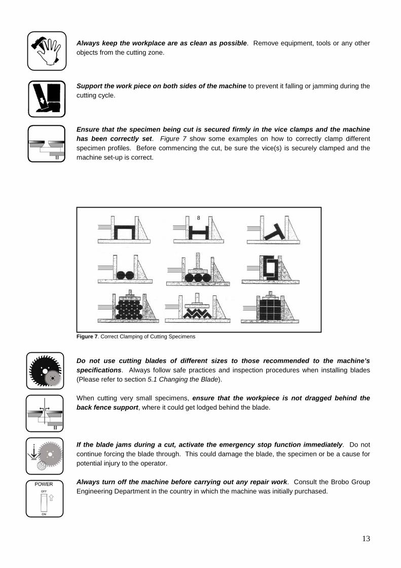
Ensure that the specimen being cut is secured firmly in the vice clamps and the machine has been correctly set. Figure 7 show some examples on how to correctly clamp different specimen profiles. Before commencing the cut, be sure the vice(s) is securely clamped and the machine set-up is correct.
Figure 7. Correct Clamping of Cutting Specimens
Do not use cutting blades of different sizes to those recommended to the machine’s specifications. Always follow safe practices and inspection procedures when installing blades (Please refer to section 5.1 Changing the Blade). When cutting very small specimens, ensure that the workpiece is not dragged behind the back fence support, where it could get lodged behind the blade. If the blade jams during a cut, activate the emergency stop function immediately. Do not continue forcing the blade through. This could damage the blade, the specimen or be a cause for potential injury to the operator.
Always turn off the machine before carrying out any repair work. Consult the Brobo Group Engineering Department in the country in which the machine was initially purchased.
8

14
2.4 Machine Safety Devices This product and maintenance manual is not purely intended as a guide for the usage, operation and maintenance of the saw unit in a strictly production environment; it is instead an instrument to providing information on how to use the machine correctly and safely. The following standards listed in section 2.4.1, which are applicable to the BW S315/S350/S400 Series Metal Cutting Saw, are those specified by the EEC Committee that governs safety of machinery, health and safety at work, personal protection and safeguarding of the work environment. In addition, the saw also complies with the Australian Standards regarding the safeguarding and general requirements for electrical equipment. 2.4.1 Reference Standards MACHINE SAFETY EEC Directive No. 98/37/CE - Machines Directive EEC Directive No. 91/368 - 94/68 - Amends sections of EEC Directive No. 98/37/CE relating to machine
safety EEC Directive No. 73/23 - Low Voltage Directive
AS4024.1 - 1996 - Safeguarding of Machinery
HEALTH AND SAFETY AT WORK AS3100 - 2002 - General Requirements for Electrical Equipment OH. & S. 1995.81/1995 - Compliance References EEC Directive No. 80/1107; 83/477; 86/188; 88/188; 88/642 - Protection of workers against risks caused by
exposure to physical, chemical and biological agents in workplace EEC Directive No. 73/23 and Special EEC Directives No. 89/654; 89/655 - Improvements in health and
safety at work
15
CHAPTER 3 - Main Functions and Operation of the Machine
ll
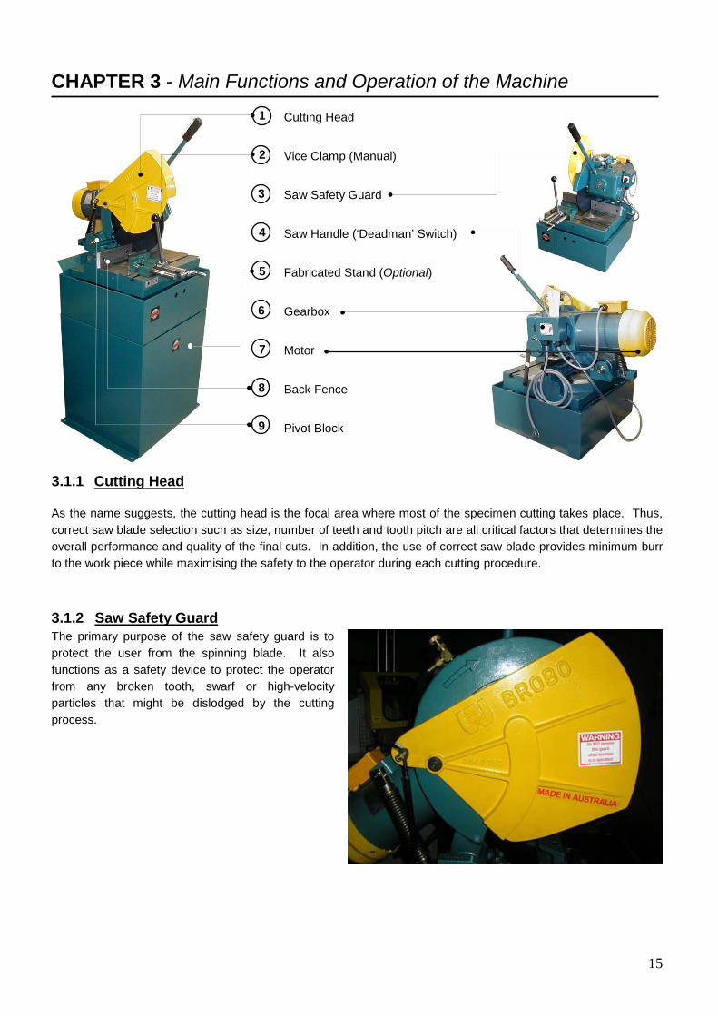
3.1.1 Cutting Head As the name suggests, the cutting head is the focal area where most of the specimen cutting takes place. Thus, correct saw blade selection such as size, number of teeth and tooth pitch are all critical factors that determines the overall performance and quality of the final cuts. In addition, the use of correct saw blade provides minimum burr to the work piece while maximising the safety to the operator during each cutting procedure. 3.1.2 Saw Safety Guard The primary purpose of the saw safety guard is to protect the user from the spinning blade. It also functions as a safety device to protect the operator from any broken tooth, swarf or high-velocity particles that might be dislodged by the cutting process.
Cutting Head Vice Clamp (Manual) Saw Safety Guard Saw Handle (‘Deadman’ Switch) Fabricated Stand (Optional) Gearbox Motor Back Fence Pivot Block
1
2
3
4
5
7
6
8
9
16
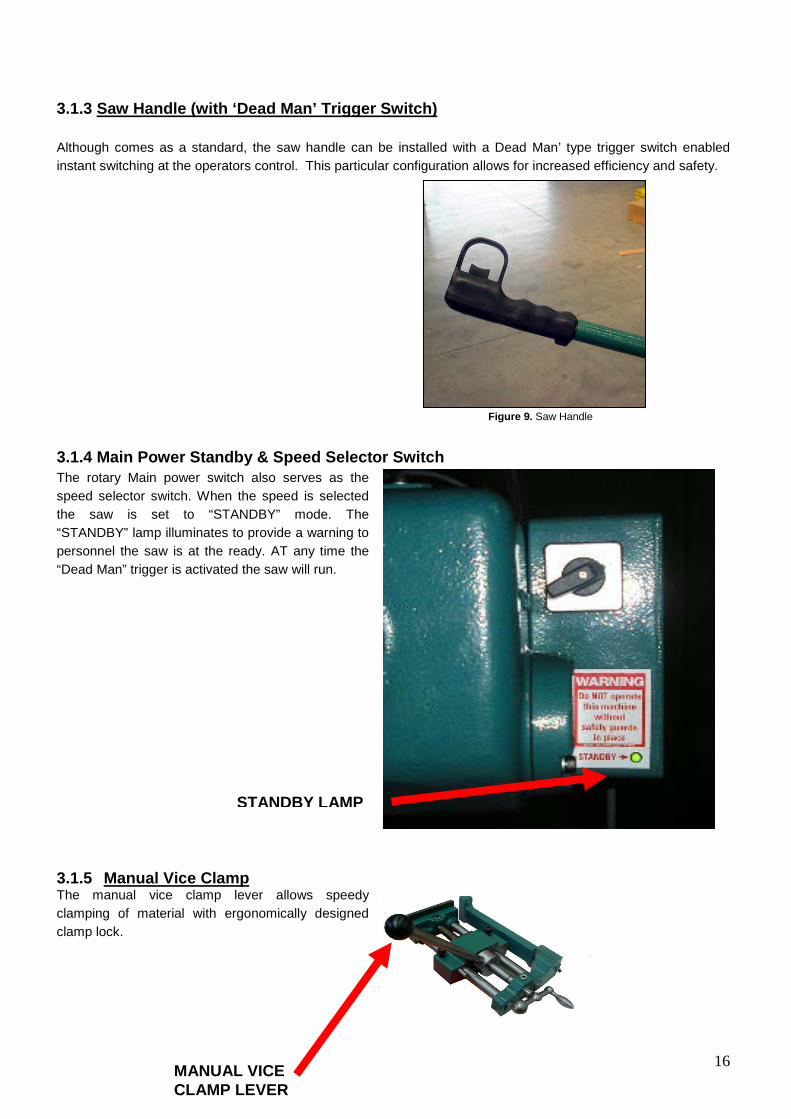
3.1.3 Saw Handle (with ‘Dead Man’ Trigger Switch) Although comes as a standard, the saw handle can be installed with a Dead Man’ type trigger switch enabled instant switching at the operators control. This particular configuration allows for increased efficiency and safety. 3.1.4 Main Power Standby & Speed Selector Switch The rotary Main power switch also serves as the speed selector switch. When the speed is selected the saw is set to “STANDBY” mode. The “STANDBY” lamp illuminates to provide a warning to personnel the saw is at the ready. AT any time the “Dead Man” trigger is activated the saw will run.
3.1.5 Manual Vice Clamp The manual vice clamp lever allows speedy clamping of material with ergonomically designed clamp lock.
Figure 9. Saw Handle
STANDBY LAMP
MANUAL VICE CLAMP LEVER
17
3.2 Preparation for Operation The following procedure is recommended for the correct cutting using the BW S315/S350/S400 Series Metal Cutting Saw. PROCEDURE
i) Using a non-flammable and toxic free solvent, clean the machine to remove any corrosion protective coating prior to use.
ii) Ensure that both the air and electric power systems are turned on, where applicable. The electrical power
source must be available before any pneumatic functions will operate.
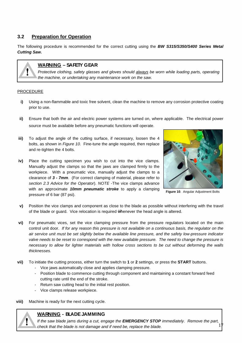
iii) To adjust the angle of the cutting surface, if necessary, loosen the 4
bolts, as shown in Figure 10. Fine-tune the angle required, then replace and re-tighten the 4 bolts.
iv) Place the cutting specimen you wish to cut into the vice clamps.
Manually adjust the clamps so that the jaws are clamped firmly to the workpiece. With a pneumatic vice, manually adjust the clamps to a clearance of 3 - 7mm. (For correct clamping of material, please refer to section 2.3 Advice for the Operator). NOTE -The vice clamps advance with an approximate 10mm pneumatic stroke to apply a clamping pressure of 6 bar (87 psi).
v) Position the vice clamps and component as close to the blade as possible without interfering with the travel
of the blade or guard. Vice relocation is required whenever the head angle is altered.
vi) For pneumatic vices, set the vice clamping pressure from the pressure regulators located on the main control unit door. If for any reason this pressure is not available on a continuous basis, the regulator on the air service unit must be set slightly below the available line pressure, and the safety low-pressure indicator valve needs to be reset to correspond with the new available pressure. The need to change the pressure is necessary to allow for lighter materials with hollow cross sections to be cut without deforming the walls thicknesses.
vii) To initiate the cutting process, either turn the switch to 1 or 2 settings, or press the START buttons.
- Vice jaws automatically close and applies clamping pressure. - Position blade to commence cutting through component and maintaining a constant forward feed cutting rate until the end of the stroke. - Return saw cutting head to the initial rest position.
- Vice clamps release workpiece.
viii) Machine is ready for the next cutting cycle.
WARNING - BLADE JAMMING
If the saw blade jams during a cut, engage the EMERGENCY STOP immediately. Remove the part, check that the blade is not damage and if need be, replace the blade.
!
Figure 10. Angular Adjustment Bolts
WARNING – SAFETY GEAR
Protective clothing, safety glasses and gloves should always be worn while loading parts, operating the machine, or undertaking any maintenance work on the saw.
!
12
18
3.3 Operation Recommendations Select the correct saw blade with the correct tooth pitch and form to suit the material to be cut to provide
minimum burr and maximum blade lifespan. Use the smallest diameter blade and coarsest pitch that is practical within the required speed and material
limitations. Generally use a tooth pitch to give 2 - 4 teeth engagement with the material during cutting.
Ensure that sufficient coolant is flowing over the cutting teeth.
Do not allow the machine’s gearbox to run idle in the upright position for more than 3 minutes otherwise,
damage can occur to the drive system. The rate of feed affects the quality of the final cut and blade life. This varies also by the material and cross-
sectional dimensions. When cutting stainless steel or high carbon steel (Brinnel Hardness above 200), the slowest speed machine should be used together with a cobalt type high speed steel blade.
When manually feeding the saw head, keep in mind to maintain a steady, continuous pressure, thus
avoiding work hardening on the cutting piece. Avoid ‘forcing’ the blade through the material as this might damage or break the blade.
As a rule of thumb the softer the component, the faster the rate of speed. Thus, it is recommended that
slower speeds be used for hard and tough materials and higher speeds for soft, ductile materials. Note that for non-ferrous materials such as brass, copper, aluminium etc. require much faster speeds than provided on this machine. If these are the majority of materials cut, a Brobo NF Series machine should be considered.
19
CHAPTER 4 - Drawings, Layouts, Assembly and Spare Parts
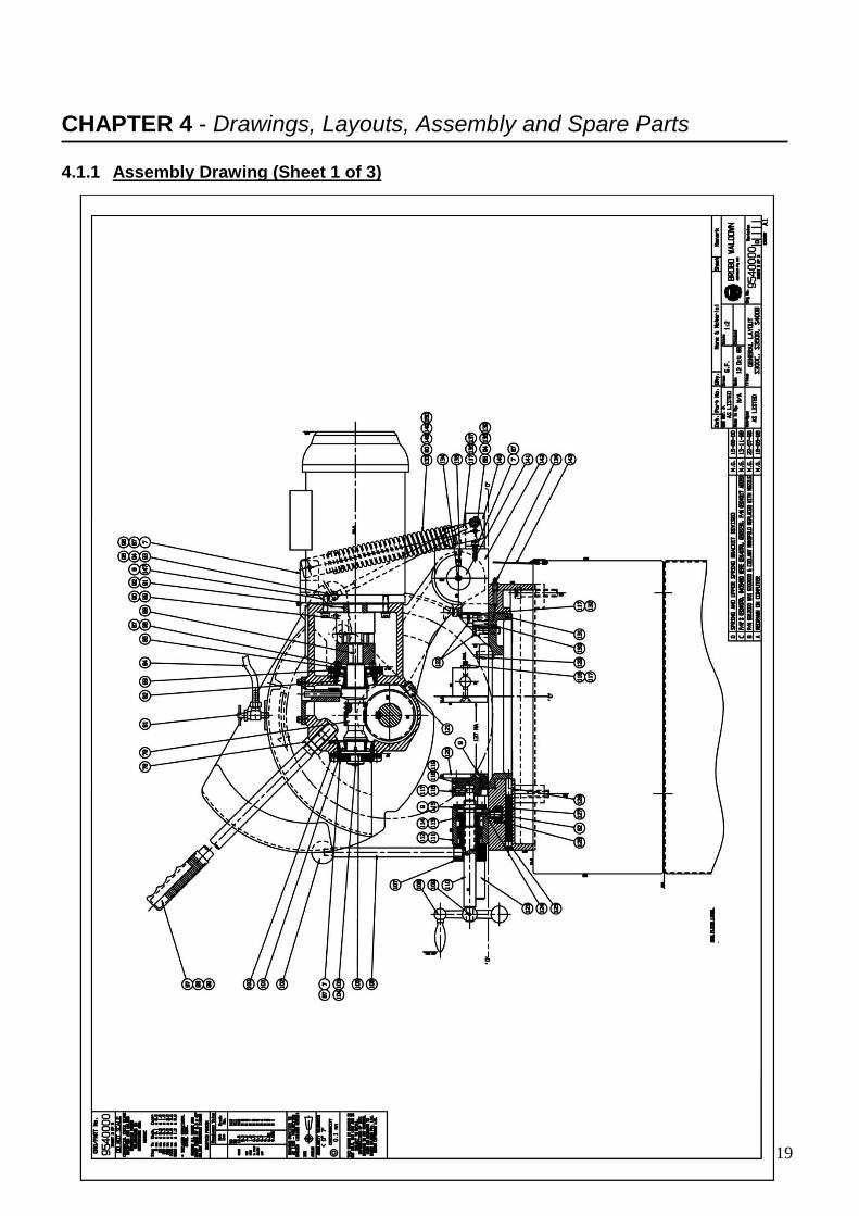
4.1.1 Assembly Drawing (Sheet 1 of 3)
20
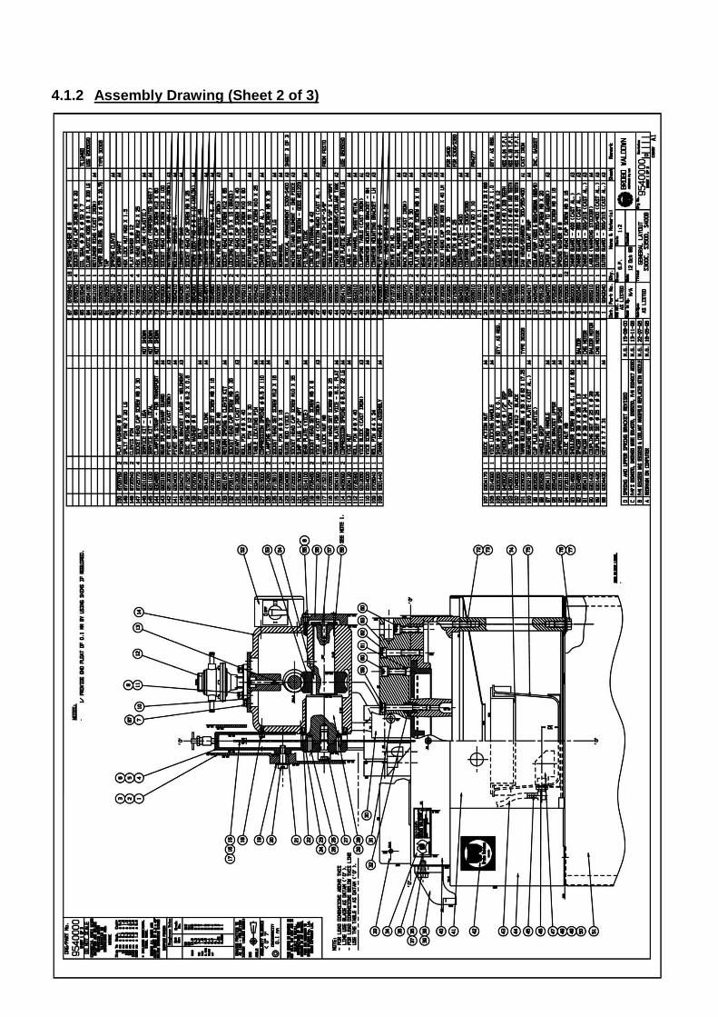
4.1.2 Assembly Drawing (Sheet 2 of 3)
21
14
22
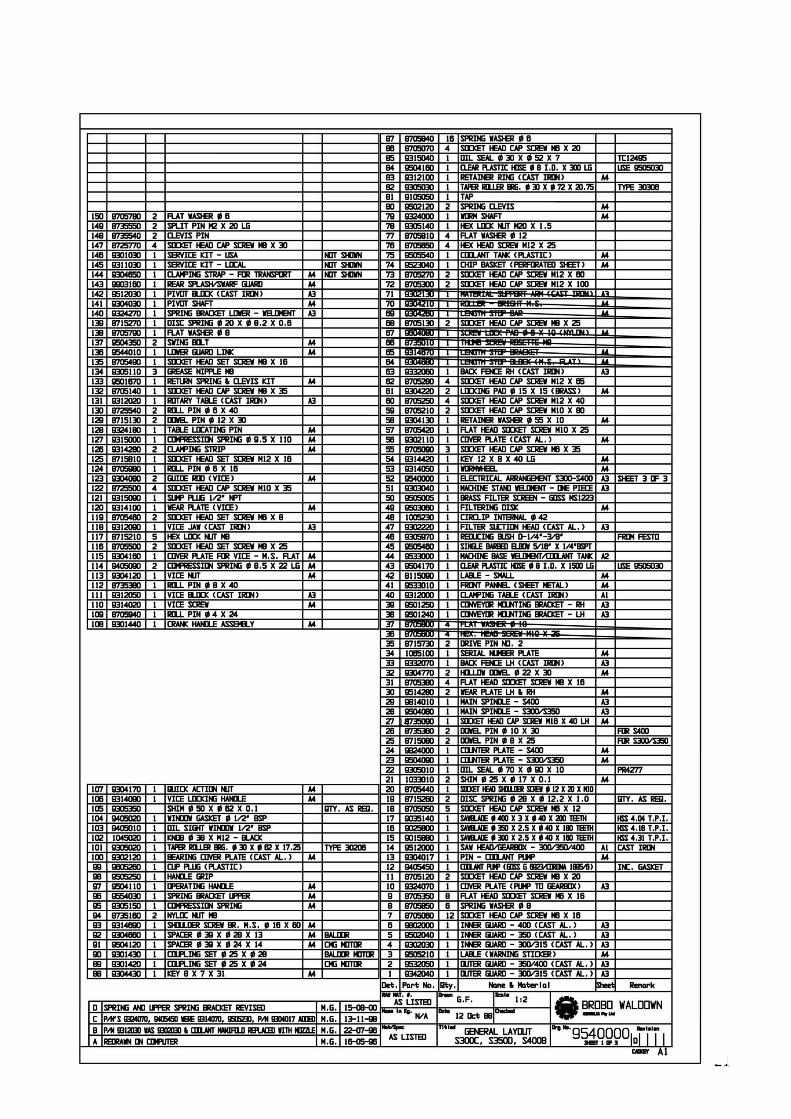
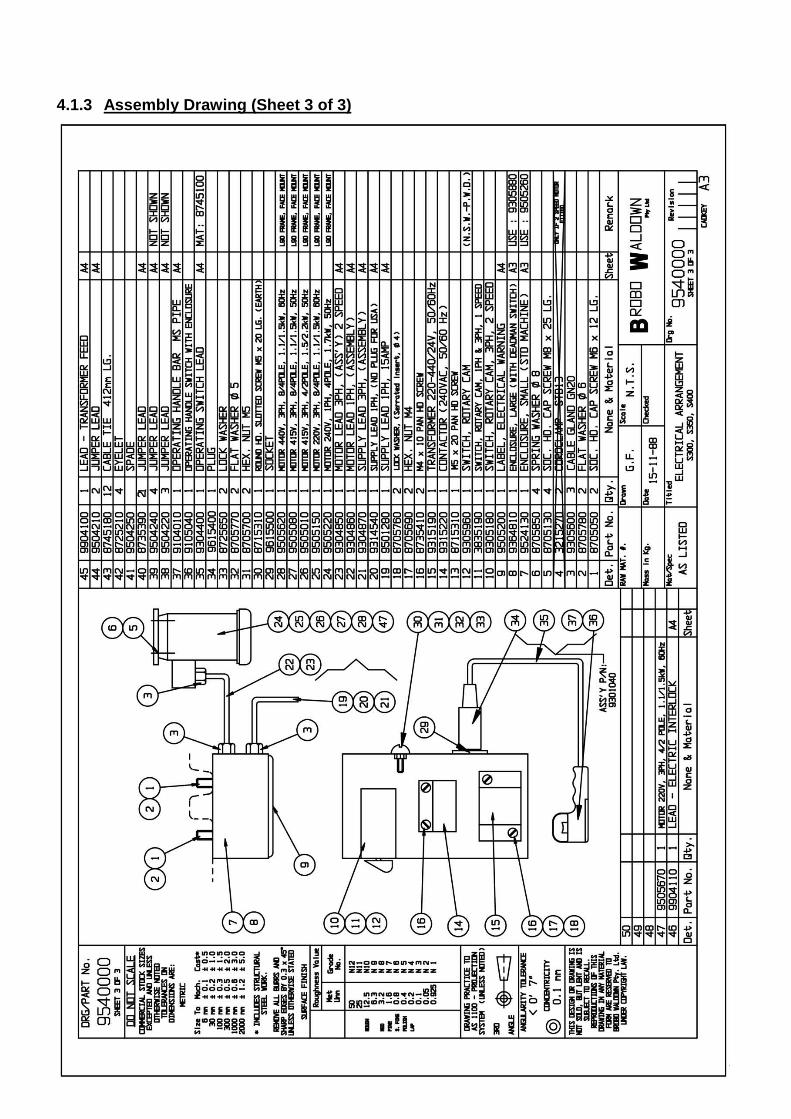
4.1.3 Assembly Drawing (Sheet 3 of 3)

23
4.2.1 Electrical Circuit 1PH/ 3PH & 3PH Dual Speed Circuit Diagram
24
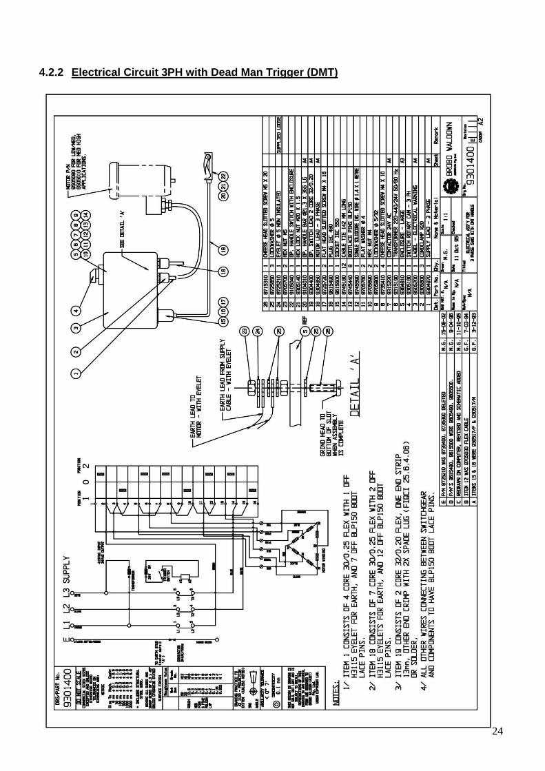
4.2.2 Electrical Circuit 3PH with Dead Man Trigger (DMT)
25
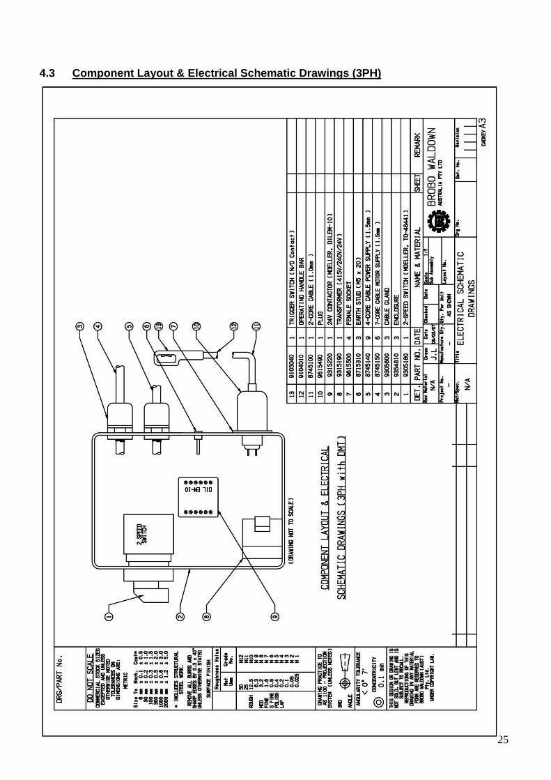
4.3 Component Layout & Electrical Schematic Drawings (3PH)
26
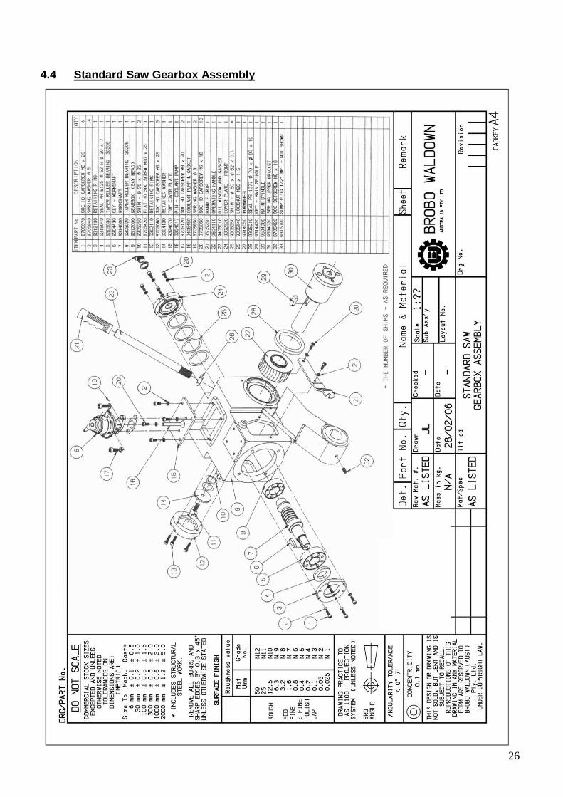
4.4 Standard Saw Gearbox Assembly
27
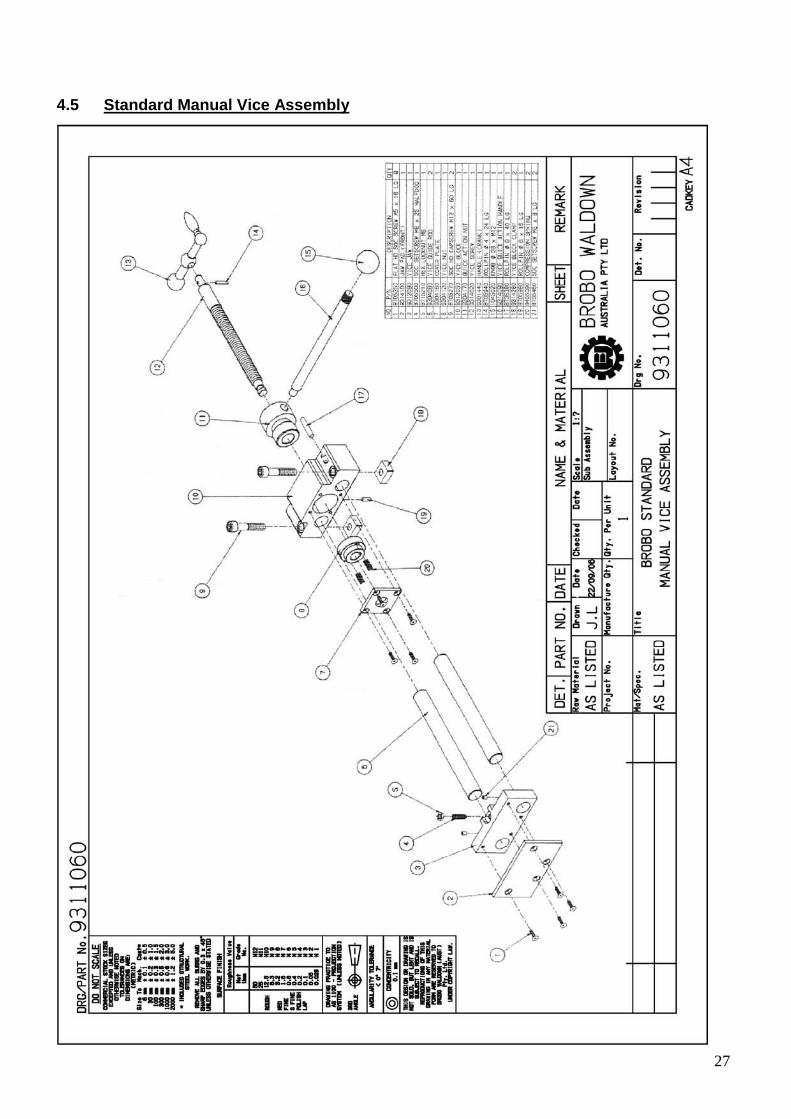
4.5 Standard Manual Vice Assembly
28
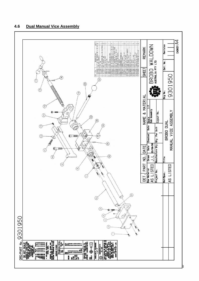
4.6 Dual Manual Vice Assembly
29
DANGER – ELECTROCUTION
Make certain that the power to the manual saw is turned off before proceeding with changing the saw blade.
CHAPTER 5 - Adjustments for the Saw Unit 5.1 Changing the Blade To replace a worn saw blade:
i) Disengage the linkage arm that is between the guard linkage system and pivot block (at the pivot block by
compressing the spring and moving the bolt through the slot).
ii) Slide the saw guard up as far as possible (as if it was opening during a cutting cycle) to gain access to the spindle nose.
iii) Loosen the spindle screws (LH thread), using the 14mm hexagonal wrench provided, and remove the
counter plate. To loosen the spindle screw, insert the wrench (short end) into the socket head cap screw and firmly knock the wrench with the palm of your hands until the screw is loosened. If this method fails to free the screw, place a piece of timber under the blade of the machine, and loosen (or tighten) the screw while holding the saw head of the machine down (blade against the timber).
iv) Remove the worn saw blade away from the spindle hub. Using a soft brush, clean the face of the spindle,
counter plate and mounting faces of the blade of any dirt or swarf that was trapped by the previous cutting cycles.
v) Place the old saw blade into the new blade packaging and disposed of it safely. Carefully mount the new
blade onto the spindle hub, ensuring that the blade is rotating into and towards the back fence, and replace the counter plate utilising the drive pins as guides as it passes through the pinholes on the blade.
vi) Rotate blade back against the drive pins in a counter-clockwise and finger tighten the spindle screw.
vii) Firmly retighten the spindle screws, ensuring that the saw blade spins uniformly and aligned parallel with
the safety guard.
viii) Lower the outer guards and make certain the pin of the linkage arm is re-engaged with the track on the inner guard and reconnect the guard linkage.
ix) The new blade is ready for use. To check that the blade is performing correctly, carry out a sample cut on
a piece of off-cut.
x) If optional devices are supplied, mount the stock support and rollers on either side of the clamping table. Normally stock should feed from left to right, but it can be feed from the right to left, if required.
30
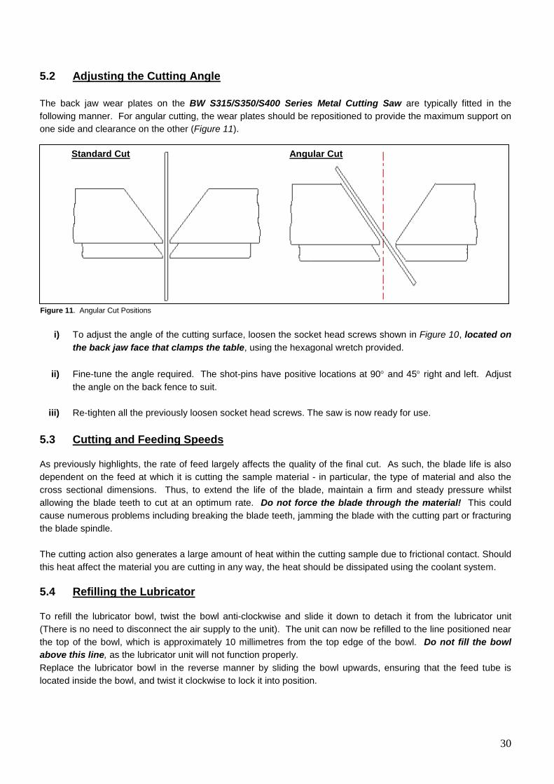
5.2 Adjusting the Cutting Angle The back jaw wear plates on the BW S315/S350/S400 Series Metal Cutting Saw are typically fitted in the following manner. For angular cutting, the wear plates should be repositioned to provide the maximum support on one side and clearance on the other (Figure 11).
i) To adjust the angle of the cutting surface, loosen the socket head screws shown in Figure 10, located on the back jaw face that clamps the table, using the hexagonal wretch provided.
ii) Fine-tune the angle required. The shot-pins have positive locations at 90° and 45° right and left. Adjust
the angle on the back fence to suit.
iii) Re-tighten all the previously loosen socket head screws. The saw is now ready for use. 5.3 Cutting and Feeding Speeds As previously highlights, the rate of feed largely affects the quality of the final cut. As such, the blade life is also dependent on the feed at which it is cutting the sample material - in particular, the type of material and also the cross sectional dimensions. Thus, to extend the life of the blade, maintain a firm and steady pressure whilst allowing the blade teeth to cut at an optimum rate. Do not force the blade through the material! This could cause numerous problems including breaking the blade teeth, jamming the blade with the cutting part or fracturing the blade spindle. The cutting action also generates a large amount of heat within the cutting sample due to frictional contact. Should this heat affect the material you are cutting in any way, the heat should be dissipated using the coolant system. 5.4 Refilling the Lubricator
To refill the lubricator bowl, twist the bowl anti-clockwise and slide it down to detach it from the lubricator unit (There is no need to disconnect the air supply to the unit). The unit can now be refilled to the line positioned near the top of the bowl, which is approximately 10 millimetres from the top edge of the bowl. Do not fill the bowl above this line, as the lubricator unit will not function properly. Replace the lubricator bowl in the reverse manner by sliding the bowl upwards, ensuring that the feed tube is located inside the bowl, and twist it clockwise to lock it into position.
Standard Cut Angular Cut
Figure 11. Angular Cut Positions
31
5.5 Adjusting the Brobolube Unit
When assembled, the Brobolube unit is a precise instrument that supplies an accurate quantity of lubricant directly to the saw blade before it contacts the work piece. There are 2 control variables available for the operator:
1) Air Flow (Volume) Delivery Regulated with the tap (needle valve), this can be adjusted from initial, completely closed to fully open states. It is highly recommended that the upper end of the flow range be utilised to allow an adequate airflow to deposit and evenly distributed the lubricant onto the blade, while maintaining a fine lubricant mix. If the needle valve is not open sufficiently, the air to lubricant ratio may vary, and may result in a substandard distribution of lubricant to reach the blade teeth.
NOTE i) Although the lubricator is capable of delivering a much higher flow rate of lubricant, it is suggested that you do
not increase the flow rate excessively because:
No significant increase in blade life or lubricating efficiency will be achieved (confirmed by test results).
Excessive application of Brobolube will only result in a waste of fluid. Excessive application will produce swarf that will be wet (oily) and harder to clean up than dry swarf
produced from the correct supply of Brobolube.
ii) The amount of Lubricant (when set correctly) delivered by the lubricator is not easily visible by the naked eye. If in doubt that lubricant is being delivered, first check to see if lubricator itself is delivering droplets at its sight glass. If still unsure whether lubricant is being delivered, disconnect the supply tubing to the tap (needle valve) and hold the tube against some blotting paper for a few seconds while the lubricator is operating.
5.5.1 Lubricating Oil Precautions - Health Hazard Information
The Brobolube lubricating fluid has no known adverse health effects. "Brobolube" is non-toxic, odourless, non-flammable below approximately 350ºC, and non-corrosive, although it may affect some types of rubber. There are no traces of sulphur, chlorine, phenol or nitrates found in Brobolube. When comes into contact with skin, the oil may be removed by wiping away the excess, then washing the contaminated area with detergent and water. If the oil is utilised at high temperatures, appropriate protective apparel should be worn as the oil could cause burns to skin or eyes. If splashed by hot oil, immediately run cold water over the burn area and apply first aid burn treatment.
If the Brobolube delivery line breaks or becomes disconnected during operation, ensure that the air supply to the system is disconnected before repairing the problem.
It is recommended that footwear with anti-slip soles be worn at all times. Any spills will result in potentially hazardous slippery surfaces and should be dealt with promptly to prevent physical injury resulting from falls. Do not use coarsely, combustible material like sawdust to soak up oil due to the potential risk of spontaneous combustion. Spilled oil should be transferred into non-porous containers of suitable strength. Any remaining oil should be cleaned up with sand or other non-combustible, absorbent material. Place the sand and oil mixture into containers and disposed of by an EPA approved landfill or alternatively, by a suitable non-polluting method. In addition, rags soaked in oil should not be burned. Do not pour oil down the drain, which would ultimately contaminate the water supply and pollute the environment.

32
For fire fighting purposes, either use CO2, dry chemical or foam retardant to extinguish the flames.
CHAPTER 6 – Maintenance and Selection of Consumables
6.1 Role of the Operator The person operating and maintaining the BW S315/S350/S400 Series Metal Cutting Saw must familiarise themselves with these instructions for their own safety and that of the others, in addition to safeguarding the production of the machine. Responsibility must be taken by the user on the general maintenance and up keeping of the unit as specified in this chapter, with particular emphasis on: Check to ensure that other operators of the machine always aware of and comply with the relevant safety
instructions and standards as specified in Chapter 2 - Safety and Accident Prevention. Therefore, check that the safety devices are operational and work perfectly and that personal safety requirements are complied with.
Ensure that the working cycle is efficient and guarantees maximum productivity, inspect the:
- Functions of the main components of the machine - Sharpness of the blade and coolant flow - Correct working parameters for the type of material being cut
Verify that the quality of the cut meets the requirements and that the final product is free from any
machining defects. 6.2 Maintenance Requirements All maintenance must be carried out with the power switched off and the machine in emergency stop
condition. To guarantee for optimum operation, all spare parts must be Brobo Group originals.
On completion of maintenance works, ensure that the replaced parts or any tools used have been
removed from the machines before starting it up. Any behaviour not in accordance with the instructions for using the machine specified in this manual may
create hazards and/or safety risks for the operator. Therefore, read and follow all the instructions for use and maintenance of the machine and those on the
product itself. 6.3 General Maintenance of Functioning Components The general maintenance operations that should be carried out regularly are as follows:
i) Keep the vice clamps, overall machine and path of the cutting blade free of any offcuts, accumulated swarf and coolant using compressed air or preferably thread-free cloth.
ii) Observe the oil level on the gearbox. The first oil change should be performed after the initial 25 hours of
operation and 300 hours of operation thereafter. Use extreme pressure industrial gear oil - ISO VG 220 viscosity, conforming to AGMA 5EP, US Steel 224 or API GL-2 specifications to which 3% colloidal molybdenum disulphide has been added. Refilling point is situated in the handle bar mounting threaded hole. The required quantity to refill is approximately 1 litre for the S315/S350/400 gearboxes. Gearbox oil is available from BROBO GROUP Pty. Ltd. in 2 Litre packs (Part No. 9501090).

33
iii) Change coolant as required, or whenever the coolant starts to get dirty or emits a stale odour. The
coolant compensation tank should be checked regularly. Coolant level would expect to naturally decrease over time due to natural evaporation. Use premium quality coolants such as CoolTech 500 or SlideTech 68. Coolant is available from BROBO GROUP Pty. Ltd. in 2 litre packs (Part No. 9301570).
iv) Lubricate the saw head pivot shaft and rotary table regularly (after every 40 hours of operation, or
weekly) with an NLGI 2 extreme pressure grease, Shell Alvania No.1 grease or equivalent. v) Clean the vice and lubricate any moving joints or sliding surfaces with good quality oil.
vi) Clean the machine regularly and keep any unpainted surfaces lightly oiled to protect from rust and
corrosion. vii) The air supply for the pneumatic air vices should be checked regularly such that it is free of any
condensed water molecules and the filter should be drained frequently.
viii) Ensure that the machine performs cuts perpendicular to the work surface. If not, contact Brobo Group engineering department.
ix) Test that the blade is at right angles to the workpiece back fence. If not, contact Brobo Group engineering
department. x) Check that the 0° notch on the fixed worktable is aligned with the gradation on the turntable. If not, adjust
as described in Section 5.2. xi) Examined that the precision of the 15°, 30°, 45° left and right stops are correct and accurate. If they are
not adjusted properly, proceed as described in Section 5.2.
34
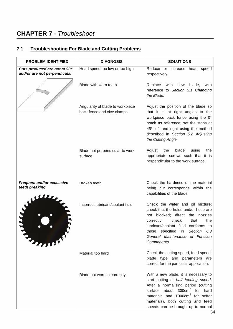
CHAPTER 7 - Troubleshoot 7.1 Troubleshooting For Blade and Cutting Problems
PROBLEM IDENTIFIED DIAGNOSIS SOLUTIONS
Cuts produced are not at 90° and/or are not perpendicular Frequent and/or excessive teeth breaking
Head speed too low or too high Blade with worn teeth Angularity of blade to workpiece back fence and vice clamps Blade not perpendicular to work surface Broken teeth Incorrect lubricant/coolant fluid Material too hard Blade not worn in correctly
Reduce or increase head speed respectively. Replace with new blade, with reference to Section 5.1 Changing the Blade. Adjust the position of the blade so that it is at right angles to the workpiece back fence using the 0° notch as reference; set the stops at 45° left and right using the method described in Section 5.2 Adjusting the Cutting Angle. Adjust the blade using the appropriate screws such that it is perpendicular to the work surface. Check the hardness of the material being cut corresponds within the capabilities of the blade. Check the water and oil mixture; check that the holes and/or hose are not blocked; direct the nozzles correctly; check that the lubricant/coolant fluid conforms to those specified in Section 6.3 General Maintenance of Function Components. Check the cutting speed, feed speed, blade type and parameters are correct for the particular application. With a new blade, it is necessary to start cutting at half feeding speed. After a normalising period (cutting surface about 300cm2 for hard materials and 1000cm2 for softer materials), both cutting and feed speeds can be brought up to normal
35
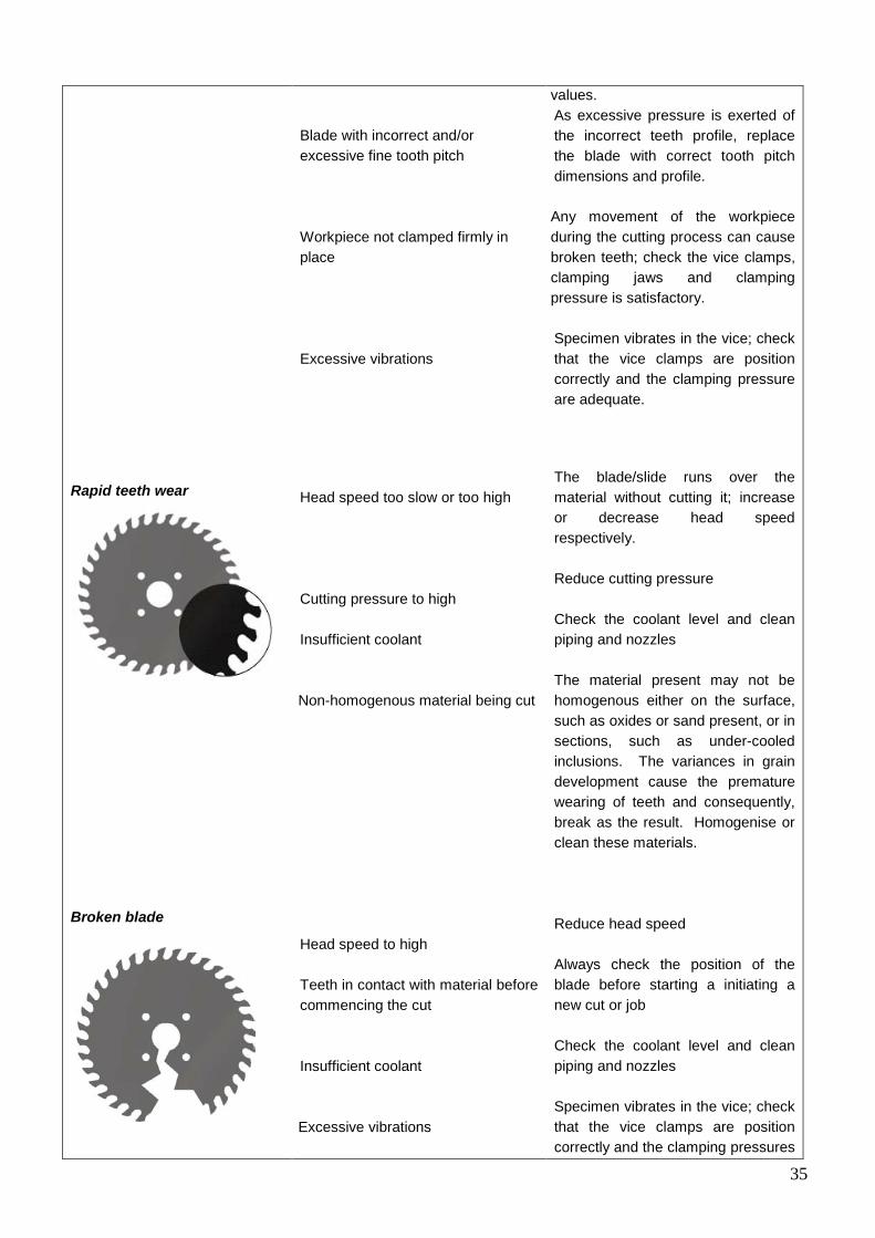
Rapid teeth wear Broken blade
Blade with incorrect and/or excessive fine tooth pitch Workpiece not clamped firmly in place Excessive vibrations
Head speed too slow or too high Cutting pressure to high Insufficient coolant Non-homogenous material being cut Head speed to high Teeth in contact with material before commencing the cut Insufficient coolant Excessive vibrations
values. As excessive pressure is exerted of the incorrect teeth profile, replace the blade with correct tooth pitch dimensions and profile. Any movement of the workpiece during the cutting process can cause broken teeth; check the vice clamps, clamping jaws and clamping pressure is satisfactory. Specimen vibrates in the vice; check that the vice clamps are position correctly and the clamping pressure are adequate. The blade/slide runs over the material without cutting it; increase or decrease head speed respectively. Reduce cutting pressure Check the coolant level and clean piping and nozzles The material present may not be homogenous either on the surface, such as oxides or sand present, or in sections, such as under-cooled inclusions. The variances in grain development cause the premature wearing of teeth and consequently, break as the result. Homogenise or clean these materials. Reduce head speed Always check the position of the blade before starting a initiating a new cut or job Check the coolant level and clean piping and nozzles Specimen vibrates in the vice; check that the vice clamps are position correctly and the clamping pressures
36
are adequate
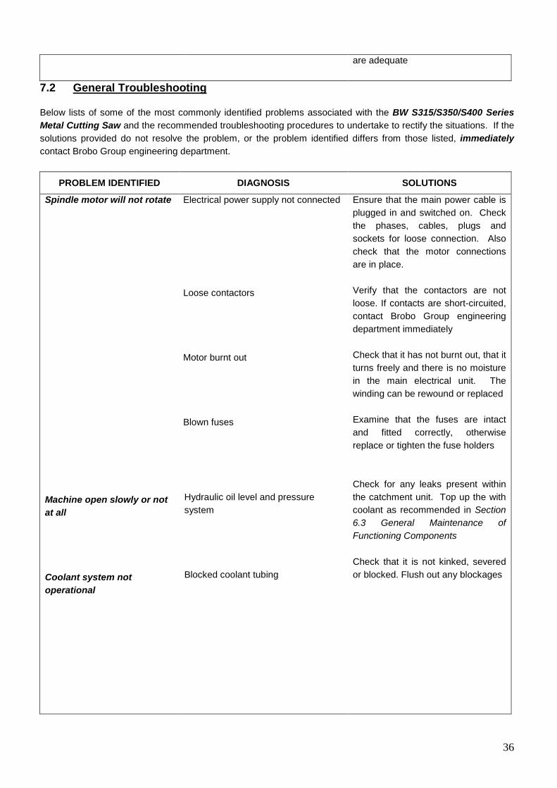
7.2 General Troubleshooting Below lists of some of the most commonly identified problems associated with the BW S315/S350/S400 Series Metal Cutting Saw and the recommended troubleshooting procedures to undertake to rectify the situations. If the solutions provided do not resolve the problem, or the problem identified differs from those listed, immediately contact Brobo Group engineering department.
PROBLEM IDENTIFIED DIAGNOSIS SOLUTIONS
Spindle motor will not rotate Machine open slowly or not at all Coolant system not operational
Electrical power supply not connected Loose contactors Motor burnt out Blown fuses Hydraulic oil level and pressure system Blocked coolant tubing
Ensure that the main power cable is plugged in and switched on. Check the phases, cables, plugs and sockets for loose connection. Also check that the motor connections are in place. Verify that the contactors are not loose. If contacts are short-circuited, contact Brobo Group engineering department immediately Check that it has not burnt out, that it turns freely and there is no moisture in the main electrical unit. The winding can be rewound or replaced Examine that the fuses are intact and fitted correctly, otherwise replace or tighten the fuse holders Check for any leaks present within the catchment unit. Top up the with coolant as recommended in Section 6.3 General Maintenance of Functioning Components Check that it is not kinked, severed or blocked. Flush out any blockages
37
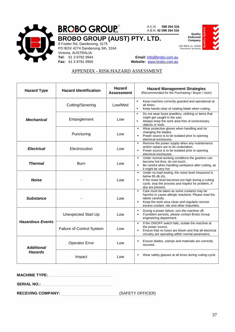
APPENDIX - RISK/HAZARD ASSESSMENT
Hazard Type Hazard Identification Hazard Assessment
Hazard Management Strategies (Recommended for the Purchasing / Buyer / User)
Mechanical
Cutting/Severing Low/Med Keep machine correctly guarded and operational at
all times. Keep hands clear of rotating blade when cutting.
Entanglement Low Do not wear loose jewellery, clothing or items that
might get caught in the saw. Always keep the work area free of unnecessary
objects or tools.
Puncturing Low Wear protective gloves when handling and /or
changing the blades. Power source is to be isolated prior to opening
electrical enclosures.
Electrical Electrocution Low Remove the power supply when any maintenance
and/or repairs are to be undertaken. Power source is to be isolated prior to opening
electrical enclosures.
Thermal Burn Low Under normal working conditions the gearbox can
become hot thus, do not touch. Be careful when handling workpiece after cutting, as
it might be very hot.
Noise - Low
Under no load testing, the noise level measured is below 85 db (A).
If the noise level becomes too high during a cutting cycle, stop the process and inspect for problem, if any are present.
Substance - Low
Care must be taken as some coolants may be harmful or cause allergic reactions. Please read the labels carefully.
Keep the work area clean and regularly remove excess coolant, oils and other impurities.
Hazardous Events
Unexpected Start Up Low During a power failure, turn the machine off. If problem persists, please contact Brobo Group
engineering department.
Failure of Control System Low If the ON/OFF switch fails, isolate the machine at
the power source. Ensure that no fuses are blown and that all electrical
circuitry are operating within normal parameters.
Additional Hazards
Operator Error Low Ensure blades, clamps and materials are correctly secured.
Impact Low Wear safety glasses at all times during cutting cycle.
MACHINE TYPE: SERIAL NO.: RECEVING COMPANY: (SAFETY OFFICER)
BROBO GROUP (AUST) PTY. LTD.
A.C.N. 098 264 316 A.B.N. 42 098 264 316
8 Fowler Rd, Dandenong, 3175 PO BOX 4274 Dandenong Sth, 3164 Victoria, AUSTRALIA. Tel: 61 3 9792 9944 Email: [email protected] Fax: 61 3 9791 9955 Website: www.brobo.com.au
Quality Endorsed Company
ISO 9001 Lic. 10292 Standards Australia Q
ual
ity
Sys
tem
34


on the
phone : 03 96460460
This is to certify
That an AS 4360 Risk Assessment has been completed
(*Subject to limitations)
Risk Control recommendations have been implemented accordingly.
The Plant system satisfies necessary requirements of the
Occupational Health and Safety Act 2004
Signed
Dated: 01 May 2009
Theo Avgoulis Plant Inspector (ASIA) *Certification is applicable only to current product specifications.
Certificate of AS 4024 & AS 3000 compliance
fax : 07 31124182email : [email protected]
web : www.avgoservices.comP.O. Box 5089 Garden City 3207 Victoria 3207
avgoservices
Brobo S315 A/D, S/SCV 350 D, S/SCV 400/B OHS Series Metal Saws Serial No's. *C29680 ~
Related Documents