OEM Networking within a Converged Plantwide Ethernet Architecture Design Guide October 2017 Cisco Reference Design Document Reference Number: ENET-TD018A-EN-P

Welcome message from author
This document is posted to help you gain knowledge. Please leave a comment to let me know what you think about it! Share it to your friends and learn new things together.
Transcript

OEM Networking within a Converged Plantwide Ethernet Architecture Design Guide
October 2017
Cisco Reference Design
Document Reference Number: ENET-TD018A-EN-P

Preface
Converged Plantwide Ethernet (CPwE) is a collection of tested and validated architectures that are developed by subject matter authorities at Cisco and Rockwell Automation. The testing and validation follow the Cisco Validated Design (CVD) and Cisco Reference Design (CRD) methodologies. The content of CPwE, which is relevant to both operational technology (OT) and informational technology (IT) disciplines, consists of documented architectures, best practices, guidance and configuration settings to help manufacturers with the design and deployment of a scalable, reliable, secure and future-ready plant-wide industrial network infrastructure. CPwE can also help manufacturers achieve cost reduction benefits using proven designs that can facilitate quicker deployment while helping to minimize risk in deploying new technology.
Expanding on the existing collection of CPwE CVDs, this CPwE CRD outlines key requirements and design considerations to help with the successful design and deployment of lightly managed industrial Ethernet switches (IES) in the Cell/Area Zone and sub-zones for connecting Industrial Automation and Control Systems (IACS) devices. Lightly managed IES are ideal for use in the manufacturing industry in several key scenarios, including OEM process skids and OEM machines. In these and similar use cases, a lightly managed IES provides easily replicable configurations to maintain many CPwE CVD networking best practices including segmentation, security and resiliency.
Document OrganizationThis document is composed of the following chapters and appendices.
Chapter/Appendix Description
CPwE Architecture Introduces the CPwE architecture and provides a closer look at the how sub-zones in the Cell/Area Zone are important in the OEM machine, skid and equipment builders.
Lightly Managed IES in the Sub-Zone
Describes feature highlights, available configurations and network considerations, and provides a comparison to fully managed switches.
Integrating Lightly Managed IES into the CPwE Architecture
Describes the basic configuration settings for the recommended deployment scenario for a lightly managed IES.
Validation Describes the testing performed on the lightly managed IES.
References Links to documents and websites that are relevant to the OEM Networking within a Converged Plantwide Ethernet Architecture CRD.
Acronyms and Initialisms List of acronyms and initialisms used in this document.
About the Cisco Validated Design (CVD) Program
Describes the Cisco Validated Design (CVD) process and the distinction between CVDs and Cisco Reference Designs (CRDs).
iiOEM Networking within a Converged Plantwide Ethernet Architecture
ENET-TD018A-EN-P
PrefaceAudience
AudienceThe main intended audience for this document are engineers and technicians at original equipment manufacturers (OEM) machine, skid and equipment builders looking for guidance in using lightly managed industrial Ethernet switches (IES) on their equipment, and integrating into the larger CPwE architecture. Readers should already be familiar with the CPwE architectures.
Document Objective and ScopeThis document briefly discusses the CPwE architecture and then focuses on the Cell/Area Zone, and sub-zones where important design and implementation considerations are examined and explained. This document is not intended to be an exhaustive analysis of every feature and option available, but instead is designed to highlight the most important capabilities of the Cisco Industrial Ethernet 1000 (IE 1000) and Allen-Bradley® Stratix® 2500 series lightly managed IES and how they relate to the CPwE architecture.
For More InformationMore information on CPwE Design and Implementation Guides can be found at the following URLs:
• Rockwell Automation site:
– http://www.rockwellautomation.com/global/products-technologies/network-technology/architectures.page?
• Cisco site:
– http://www.cisco.com/c/en/us/solutions/enterprise/design-zone-manufacturing/landing_ettf.html
Note This release of the CPwE architecture focuses on EtherNet/IP™, which uses the ODVA Common Industrial Protocol (CIP™) and is ready for the Industrial Internet of Things (IIoT). For more information on EtherNet/IP, see odva.org at the following URL:
• http://www.odva.org/Technology-Standards/EtherNet-IP/Overview
iiiOEM Networking within a Converged Plantwide Ethernet Architecture
ENET-TD018A-EN-P

PrefaceFor More Information
ivOEM Networking within a Converged Plantwide Ethernet Architecture
ENET-TD018A-EN-P

OEM Networking within a Con
ENET-TD018A-EN-P
C H A P T E R 1
CPwE ArchitectureThis chapter, which introduces the CPwE architecture and then provides a closer look at the how sub-zones in the Cell/Area Zone are important to OEM machine, skid and equipment builders, includes the following major topics:
• Plant-wide Zoning, page 1-1
• Cell/Area Zone, page 1-5
For additional information about CPwE architectures as a whole, readers should review the CPwE Design and Implementation Guide, which can be found at the following URLs:
• Cisco site:
– http://www.cisco.com/c/dam/en/us/td/docs/solutions/Verticals/CPwE/CPwE-CVD-Sept-2011.pdf
• Rockwell Automation site:
– http://literature.rockwellautomation.com/idc/groups/literature/documents/td/enet-td001_-en-p.pdf
Plant-wide ZoningThe CPwE logical model employs the commonly used industry standards such as Purdue Model for Control Hierarchy (reference ISBN 1-55617-265-6) to organize the plant functions into Levels, and IEC-62443 (formerly ISA99) to organize the Levels into functional and security Zones, as shown in Figure 1-1.
Figure 1-1 CPwE Logical Zoning Based on Purdue Model and IEC-62443
1-1verged Plantwide Ethernet Architecture

Chapter 1 CPwE ArchitecturePlant-wide Zoning
Starting at the bottom of the CPwE logical model, the Cell/Area Zone contains three levels of IACS devices:
• Level 0 Process—Industrial sensors, drives, actuators and similar devices that interact with the physical environment by taking measurements or performing actions such as starting a motor or moving a robot arm.
• Level 1 Basic Control—Controllers, such as programmable logic controllers, distributed control system and programmable automation controllers that communicate directly with the Level 0 devices, other controllers and higher level IACS applications.
• Level 2 Area Supervisory Control—Operator interfaces including human machine interface (HMI), alarm systems and control room workstations.
The Industrial Zone contains (Levels 0-3) IACS applications that maintain site level control of the lower level IACS applications and include reporting, scheduling, file and patch servers, and network services such as Network Time Protocol (NTP), Domain Name Server (DNS), Dynamic Host Configuration Protocol (DHCP) and Active Directory. One or more of the Cell/Area Zones (described above) actually reside within the Industrial Zone, as depicted in Figure 1-1.
CPwE includes an additional zone, based on IEC-62443, sitting between the Industrial and Enterprise Zones called the Industrial Demilitarized Zone (IDMZ). The IDMZ provides a layer of separation between the traditional IT and OT operated areas of the network, allowing only traffic that is absolutely required to securely traverse the zone.
The Enterprise Zone, which contains Level 4 and Level 5, provides access to the Internet and higher-order network applications such as email, database, business-to-business (B2B) and business-to-consumer (B2C) applications and other non-critical resources. This zone, which is often seen as a source of security threats to the Industrial Zone resources, is typically managed by the IT department..
Figure 1-2 depicts the CPwE architecture network topology. Notice the separation of the zones within the network, and the different IACS devices and applications residing in each.
1-2OEM Networking within a Converged Plantwide Ethernet Architecture
ENET-TD018A-EN-P

Chapter 1 CPwE ArchitecturePlant-wide Zoning
Figure 1-2 CPwE Architecture
Multiple Cell/Area Zones, each containing different types of connectivity topologies, reside at the edge of the IACS application and overall CPwE architecture. The lightly managed IES that are highlighted by a green rectangle representing where a lightly managed IES could be placed. As discussed in Cell/Area Zone, page 1-5, several different supported topologies exist for connecting these lightly managed IES to the rest of the plant-wide network.
A simplified view of the logical CPwE architecture is depicted in Figure 1-3. It shows how multiple Cell/Area Zones (for example, packaging and processing), all aggregated and communicating with IACS applications in higher levels of the CPwE Logical Model when necessary, are possible.
1-3OEM Networking within a Converged Plantwide Ethernet Architecture
ENET-TD018A-EN-P
Chapter 1 CPwE ArchitecturePlant-wide Zoning
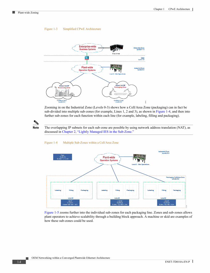
Figure 1-3 Simplified CPwE Architecture
Zooming in on the Industrial Zone (Levels 0-3) shows how a Cell/Area Zone (packaging) can in fact be sub-divided into multiple sub-zones (for example, Lines 1, 2 and 3), as shown in Figure 1-4, and then into further sub-zones for each function within each line (for example, labeling, filling and packaging).
Note The overlapping IP subnets for each sub-zone are possible by using network address translation (NAT), as discussed in Chapter 2, “Lightly Managed IES in the Sub-Zone.”
Figure 1-4 Multiple Sub-Zones within a Cell/Area Zone
Figure 1-5 zooms further into the individual sub-zones for each packaging line. Zones and sub-zones allows plant operators to achieve scalability through a building block approach. A machine or skid are examples of how these sub-zones could be used.
1-4OEM Networking within a Converged Plantwide Ethernet Architecture
ENET-TD018A-EN-P
Chapter 1 CPwE ArchitectureCell/Area Zone
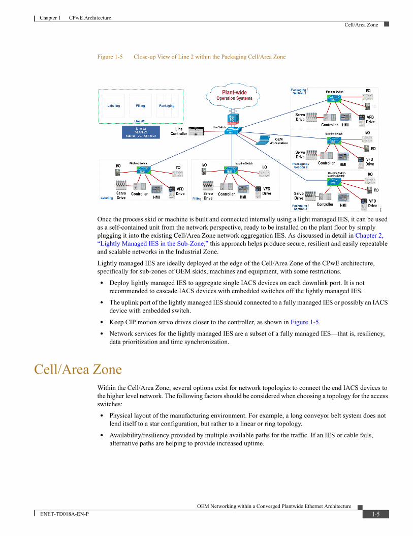
Figure 1-5 Close-up View of Line 2 within the Packaging Cell/Area Zone
Once the process skid or machine is built and connected internally using a light managed IES, it can be used as a self-contained unit from the network perspective, ready to be installed on the plant floor by simply plugging it into the existing Cell/Area Zone network aggregation IES. As discussed in detail in Chapter 2, “Lightly Managed IES in the Sub-Zone,” this approach helps produce secure, resilient and easily repeatable and scalable networks in the Industrial Zone.
Lightly managed IES are ideally deployed at the edge of the Cell/Area Zone of the CPwE architecture, specifically for sub-zones of OEM skids, machines and equipment, with some restrictions.
• Deploy lightly managed IES to aggregate single IACS devices on each downlink port. It is not recommended to cascade IACS devices with embedded switches off the lightly managed IES.
• The uplink port of the lightly managed IES should connected to a fully managed IES or possibly an IACS device with embedded switch.
• Keep CIP motion servo drives closer to the controller, as shown in Figure 1-5.
• Network services for the lightly managed IES are a subset of a fully managed IES—that is, resiliency, data prioritization and time synchronization.
Cell/Area ZoneWithin the Cell/Area Zone, several options exist for network topologies to connect the end IACS devices to the higher level network. The following factors should be considered when choosing a topology for the access switches:
• Physical layout of the manufacturing environment. For example, a long conveyor belt system does not lend itself to a star configuration, but rather to a linear or ring topology.
• Availability/resiliency provided by multiple available paths for the traffic. If an IES or cable fails, alternative paths are helping to provide increased uptime.
1-5OEM Networking within a Converged Plantwide Ethernet Architecture
ENET-TD018A-EN-P

Chapter 1 CPwE ArchitectureCell/Area Zone
• Latency and jitter should be minimized in general, but especially when connected devices are relying on real-time communication for proper operation. This is done by applying data prioritization through quality of services (QoS), time synchronization through IEEE 1588 precision time protocol (PTP), and reducing the number of hops the traffic must traverse and by making sure the network devices in the path are not congested or over-utilized.
With these considerations in mind, the CPwE architecture supports the following topologies for the Cell/Area Zone, comprised of fully managed IES such as the Cisco IE 2000, Cisco IE 3000, Cisco IE 4000, Allen-Bradley Stratix 5400, Stratix 5700, Stratix 8000 and Stratix 8300 series industrial managed switches.
Linear Topology
In a linear topology, as shown in Figure 1-6, Layer 2 access IES are connected in a chain, with one IES on the end of the chain connecting to a Layer 3 distribution switch. IACS devices and any other endpoints connect to the various IES in the chain of IES. This topology is very common for OEMs and is simple and easy to implement; however, it introduces a bottleneck at the connection to the Layer 3 distribution switch that can lead to degraded performance if the connection is oversubscribed. This topology does not factor in any resiliency. If a single IES or link fails, a loss of connectivity will occur for all IACS devices at or behind the point of failure.
Figure 1-6 Linear Topology
Ring Topology
A ring topology, as shown in Figure 1-7, improves on the linear topology by connecting both ends of the chain of Layer 2 IES back to an IES or the Layer 3 distribution switch as shown. This provides basic resiliency to the IES in the Cell/Area Zone by creating an alternate path for traffic to flow in the event of a single failure. In order to implement this topology, a loop prevention mechanism, such as Rapid Spanning Tree Protocol (RSTP), Resilient Ethernet Protocol (REP), or Device Level Ring (DLR) protocol (all IES ring), must be configured. Note that the lightly managed IES only supports RSTP.
1-6OEM Networking within a Converged Plantwide Ethernet Architecture
ENET-TD018A-EN-P
Chapter 1 CPwE ArchitectureCell/Area Zone
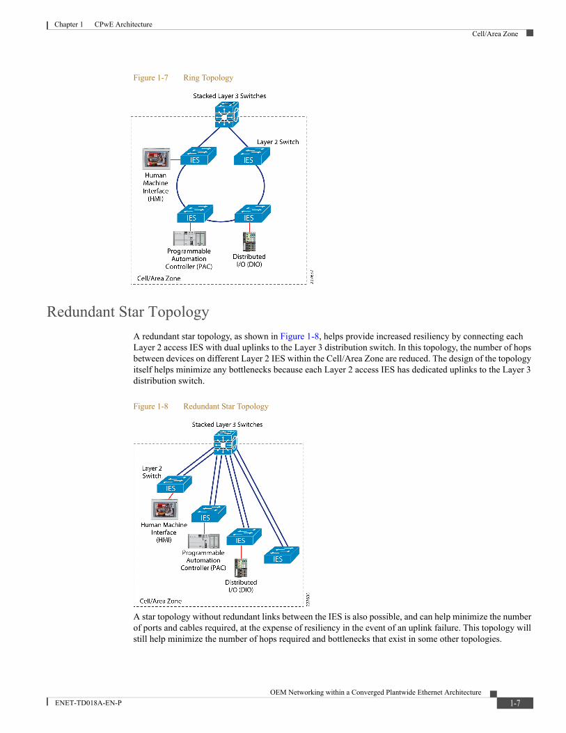
Figure 1-7 Ring Topology
Redundant Star Topology
A redundant star topology, as shown in Figure 1-8, helps provide increased resiliency by connecting each Layer 2 access IES with dual uplinks to the Layer 3 distribution switch. In this topology, the number of hops between devices on different Layer 2 IES within the Cell/Area Zone are reduced. The design of the topology itself helps minimize any bottlenecks because each Layer 2 access IES has dedicated uplinks to the Layer 3 distribution switch.
Figure 1-8 Redundant Star Topology
A star topology without redundant links between the IES is also possible, and can help minimize the number of ports and cables required, at the expense of resiliency in the event of an uplink failure. This topology will still help minimize the number of hops required and bottlenecks that exist in some other topologies.
1-7OEM Networking within a Converged Plantwide Ethernet Architecture
ENET-TD018A-EN-P

OEM Networking within a Con
ENET-TD018A-EN-P
C H A P T E R 2
Lightly Managed IES in the Sub-ZoneThis chapter includes the following major topics:
• Highlights, page 2-1
• Network Considerations, page 2-2
• Comparison to Fully Managed Switches, page 2-4
The Cisco IE 1000 and Allen-Bradley Stratix 2500 series lightly managed industrial Ethernet switches (IES) provide machine level connectivity at the edge of the CPwE architecture. Designed from the ground up to operate in demanding industrial environments, these switches include capabilities for reliably, securely and easily connecting IACS equipment in a small, cost-effective package.
Highlights• Variety of Port Configurations—These include FastEthernet and copper and between 5 and 10 ports
per switch.
• Easy Integration—Zero-touch IP discovery or DHCP IP addressing and simple web GUI-based management.
• Fast Startup Time—Starts 30 seconds from cold boot.
• Manageability—Web GUI interface, Studio 5000 Logix Designer® for the Allen-Bradley Stratix 2500 only, and diagnostics and analysis options through Simple Network Management Protocol (SNMP) and syslog.
• Security—Secure access; port-security.
• Minimize Data Load—Internet Group Management Protocol (IGMP) and DHCP snooping to filter unwanted data.
• Logical Segmentation in a Single Switch—Virtual LAN (VLAN) support allows for logical segmentation in a single switch, which reduces total number of necessary switches.
• Lightly Managed—Rapid Spanning Tree Protocol (RSTP), Link Layer Discovery Protocol (LLDP), Cisco Discovery Protocol (CDP)-aware.
• Gigabit Uplink—Two SFP-based fiber optics; uplink for up to 50 miles (80 kilometers) links.
• Industrial Power over Ethernet (PoE)—Up to eight PoE (IEEE 802.af) and PoE+ (802.3at) supported on selected models.
2-1verged Plantwide Ethernet Architecture
Chapter 2 Lightly Managed IES in the Sub-ZoneNetwork Considerations
• Redundant voltage feeds, alarm relays support and DIN rail mount.
• Industrial environmental compliance and certifications.
For detailed product specifications, refer to the following official documentation.
• Cisco Industrial Ethernet 1000 Series Switches Data Sheet at the following URL:
– http://www.cisco.com/c/en/us/products/collateral/switches/industrial-ethernet-1000-series-switches/datasheet-c78-737277.html?cachemode=refresh
• Allen-Bradley Stratix Ethernet Device Specifications (Technical Data) at the following URL:
– http://ab.rockwellautomation.com/Networks-and-Communications/Stratix-2500-Lightly-Managed
Network ConsiderationsThis section describes some of the most important considerations for designing and implementing the Cell/Area Zone (and sub-zones), using features available on the lightly managed IES. For a more detailed discussion of these and other considerations, refer to The OEM Guide to Networking from Rockwell Automation at the following URL:
• http://literature.rockwellautomation.com/idc/groups/literature/documents/rm/enet-rm001_-en-p.pdf
Network Segmentation (Zoning) and Addressing
IEC 62443 and the Purdue model illustrate the value and importance of a segmented industrial automation network. Network segmentation refers to logically (or physically) separating the network (and, more importantly, devices on the network) into multiple smaller networks based on IACS functionality zoning (scalable building blocks), for purposes that include traffic control, security (IEC 62443 zoning) or management efficiency.
Within a network, various types of traffic are typically broadcast to every host (for example, IACS device), which can quickly use up available bandwidth or expose sensitive data to unwanted recipients. By limiting the size of these Layer 2 networks (referred to as broadcast domains), traffic storms and reachability can be more tightly restricted. Segmenting the network based on physical location, function of the IACS end devices or similar factors is recommended. In Figure 1-4 on page 1-4, for example, the manufacturing plant is divided into three production lines, each with its own subnetwork.
Two basic methods exist for segmenting a Layer 2 network. Traditionally segmentation has often been accomplished with using one (or more) basic physical unmanaged switch per subnetwork. Segmentation can quickly become expensive because of the number of switches required to support different networks and the high potential for unused switch ports in areas with a small number of devices that need to be connected to a network.
In addition to segmentation with multiple switches, the second, preferred, method for segmenting the network is to logically separate the network using Virtual Local Area Networks (VLANs) within the IES. In this way a single IES can carry many different networks (or broadcast domains) on the IES, while allowing the network to still remain distinct and separate. Each physical port on the IES can be assigned to a specific VLAN, meaning that the device connected to that port can only communicate with other devices connected to different switch ports within the same VLAN. A single VLAN can potentially span across many different IES. When two IES need to connect to each other, they typically do so using ports configured as trunks that allow multiple VLANs to traverse the connection simultaneously, while staying separated by the use of a VLAN tag in the Ethernet frame header.
2-2OEM Networking within a Converged Plantwide Ethernet Architecture
ENET-TD018A-EN-P

Chapter 2 Lightly Managed IES in the Sub-ZoneNetwork Considerations
Each VLAN is assigned an IP subnetwork, which is a range of IP addresses that devices within the subnet use to communicate with each other. In order for devices to communicate with devices outside of their subnet/VLAN, they need to go through a Layer 3 IES. OEMs often want to use common IP addressing schemas for their IACS applications, where they often duplicate the build of machines, skids or equipment. In this case, the subnet would be contained within the IACS application-only used for communication between the IACS devices. Duplication of the OEM application, including the IP addressing schema, enables a common network configuration across the plant floor. Caution should be used when overlapping or identical IP addressing is used in multiple parts of the plant-wide IACS network. Network edge devices may communicate directly with common network applications that may not be capable of distinguishing between two devices with the same IP address. To resolve IP address duplication issues, NAT can be configured at the fully managed IES, functioning as the boundary of the VLAN and subnet. NAT, and more specifically Layer 2 NAT (L2NAT), works by maintaining a mapping of an IP address within the overlapping subnets and a unique address that is reachable by the rest of the network. The fully managed IES with NAT capability could then be used to aggregate the lightly managed IES.
Chapter 3, “Integrating Lightly Managed IES into the CPwE Architecture” contains additional information on network segmentation.
Note The lightly managed IES does not support NAT.
Data Prioritization
Within an industrial environment, applications that have very strict network requirements exist to help ensure that their application messages get through the network reliably and quickly. Latency and jitter must be minimized as much as possible, especially at the edge of the network where critical IACS devices are communicating directly with each other to operate physical equipment and processes.
When a network experiences high levels of load, it will be forced to start queuing packets and potentially dropping/discarding some of them if the network cannot physically accommodate all of the traffic. In scenarios like this, critical application data such as IACS protocols must be given priority over less important types of traffic. Quality of Service (QoS) generically refers to a set of features that help facilitate that specific types of traffic are given preference over others. Giving priority to IACS protocols such as CIP or PROFINET helps to make sure that they do not have wait in a queue behind less critical data, or get dropped during times of congestion.
Note The lightly managed IES does not support CIP QoS policies for time critical IACS applications such as motion control.
Resiliency
Network resiliency is critical when the operation of the manufacturing plant machinery depends on it. Resiliency should be built into every level and layer of the network to help confirm that (whenever possible), no single point of failure in the network can cause an outage. Within the Cell/Area Zone, the IES should be connected redundantly to give traffic an alternate path in the event of a device or link failure. As discussed in the first chapter, deploying switches in ring or redundant star topologies is highly recommended, along with implementing redundancy protocols such as REP.
2-3OEM Networking within a Converged Plantwide Ethernet Architecture
ENET-TD018A-EN-P
Chapter 2 Lightly Managed IES in the Sub-ZoneComparison to Fully Managed Switches
Note The lightly managed IES only supports RSTP for ring topologies and EtherChannel for redundant star topologies.
For an OEM application, using STP (or its improved variants like Multiple STP or Rapid STP) allows the lightly managed IES to protect itself from loops when using multiple redundant uplinks, while helping it to re-converge over an alternative path if a primary, active link goes down.
Using Link Aggregation Control Protocol (LACP)-based EtherChannels allow IES, even for OEM applications, to connect to the aggregation switch using two uplinks (both active) and automatically load balance traffic across them. In that one of the uplinks fails, the switches can dynamically shift all traffic to the remaining interface in the EtherChannel.
Security
CPwE is designed to address security using a holistic defense in depth approach, using multiple technologies, across all levels of a plant-wide architecture. This approach helps to prevent issues before they happen, identify anything that is able to penetrate defenses and help remediate future incidents.
Within the Cell/Area Zone, one of the simplest means of enforcing security is preventing new, unwanted devices from connecting to the network and potentially accessing sensitive resources. A simple unmanaged switch will generally allow anything that plugs into it full access to all available resources. The port-security feature in the lightly managed IES helps combat this issue by monitoring the devices (by their MAC address) that are connected to each switch port. The IES can be configured to permit a certain number of learned devices to communicate using a specific port. If additional devices (identified by a new MAC address) are detected on the same port, the IES can react in several different ways either to continue forwarding traffic from known devices and alert the administrator of new devices or to completely shut down the interface.
Multicast
Multicast traffic within the Cell/Area Zone should be considered carefully when designing and implementing the IACS network. Various industrial protocols rely on multicast transmissions in which a single source needs to simultaneously talk to multiple hosts. A host can use IGMP to signal to the network that it wants to receive multicast packets sent to a specific group or IP address. Without IGMP enabled in the Cell/Area Zone, multicast packets will behave like broadcast packets that are forwarded out every port in the Layer 2 network (VLAN). This can mean that potentially a lot of data that is not desired traverses the network, which leads to congestion or security concerns if the multicast packets contain sensitive information that not all hosts should see. The lightly managed IES can monitor the network for IGMP control messages using a feature called IGMP Snooping. Using this feature, the switch can learn which of its ports are connected to hosts that have joined a specific multicast group. The multicast traffic for this group will only be forwarded out these ports. As more and more devices are connected to the network, the control of multicast/broadcast packets with IGMP snooping and other methods becomes much more important.
Comparison to Fully Managed SwitchesThe lightly managed IES are ideal for deployment as OEM skid, machine and Equipment IES and in the Cell/Area Zone (and especially sub-zones). Cisco and Rockwell Automation offer other industrial switches that are considered fully managed. Depending on customer requirements, these switches may be a better fit for certain scenarios. They offer additional options for port types and configurations and support for more
2-4OEM Networking within a Converged Plantwide Ethernet Architecture
ENET-TD018A-EN-P
Chapter 2 Lightly Managed IES in the Sub-ZoneComparison to Fully Managed Switches
advanced network features such as Layer 3 routing, additional resiliency protocols such as REP and DLR and Flex Links and additional security features such as IEEE 802.1x. The full list of differences is available in the official documentation and is outside the scope of this CRD. Visit the following links to find information about the full line-ups of Cisco and Allen-Bradley IES:
• Cisco Industrial Ethernet Switches at the following URL:
– http://www.cisco.com/c/en/us/products/switches/industrial-ethernet-switches/index.html
• Rockwell Automation/Allen-Bradley EtherNet/IP Network at the following URL:
– http://ab.rockwellautomation.com/Networks-and-Communications/Ethernet-IP-Network
2-5OEM Networking within a Converged Plantwide Ethernet Architecture
ENET-TD018A-EN-P

OEM Networking within a Con
ENET-TD018A-EN-P
C H A P T E R 3
Integrating Lightly Managed IES into the CPwE ArchitectureThis chapter includes the following major topics:
• Connecting and Segmenting Access Ports to IACS Devices, page 3-2
• VLANs Trunked to Upstream Fully Managed IES, page 3-4
• Port Priority for Latency Sensitive IACS Device, page 3-4
• Layer 2 NAT on Managed IES, page 3-6
This chapter covers the basic configuration settings for the recommended deployment scenario for a lightly managed IES. In the examples that follow, which are applicable for the Cisco IE 1000 and Allen-Bradley Stratix 2500 lightly managed switches, the lightly managed IES is part of a process skid that contains several IACS devices. The lightly managed IES connects the IACS devices to an existing ring of managed IES switches.
Figure 3-1 Example Configuration Scenario for Lightly Managed IES
3-1verged Plantwide Ethernet Architecture
Chapter 3 Integrating Lightly Managed IES into the CPwE ArchitectureConnecting and Segmenting Access Ports to IACS Devices
Connecting and Segmenting Access Ports to IACS DevicesThe lightly managed IES support VLANs for segmenting the switch into multiple Layer 2 networks (smaller broadcast domains), as discussed in Lightly Managed IES in the Sub-Zone. This segmentation can help increase security and help reduce bandwidth utilization from unnecessary packet flooding (broadcast traffic).
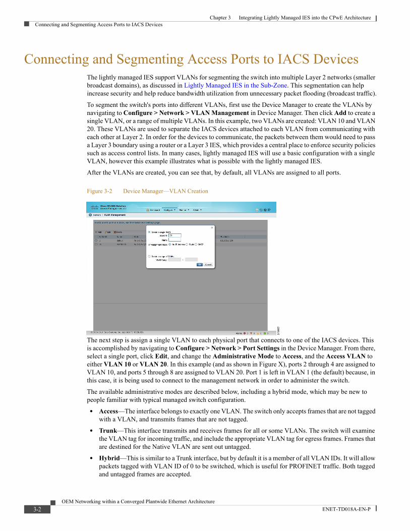
To segment the switch's ports into different VLANs, first use the Device Manager to create the VLANs by navigating to Configure > Network > VLAN Management in Device Manager. Then click Add to create a single VLAN, or a range of multiple VLANs. In this example, two VLANs are created: VLAN 10 and VLAN 20. These VLANs are used to separate the IACS devices attached to each VLAN from communicating with each other at Layer 2. In order for the devices to communicate, the packets between them would need to pass a Layer 3 boundary using a router or a Layer 3 IES, which provides a central place to enforce security policies such as access control lists. In many cases, lightly managed IES will use a basic configuration with a single VLAN, however this example illustrates what is possible with the lightly managed IES.
After the VLANs are created, you can see that, by default, all VLANs are assigned to all ports.
Figure 3-2 Device Manager—VLAN Creation
The next step is assign a single VLAN to each physical port that connects to one of the IACS devices. This is accomplished by navigating to Configure > Network > Port Settings in the Device Manager. From there, select a single port, click Edit, and change the Administrative Mode to Access, and the Access VLAN to either VLAN 10 or VLAN 20. In this example (and as shown in Figure X), ports 2 through 4 are assigned to VLAN 10, and ports 5 through 8 are assigned to VLAN 20. Port 1 is left in VLAN 1 (the default) because, in this case, it is being used to connect to the management network in order to administer the switch.
The available administrative modes are described below, including a hybrid mode, which may be new to people familiar with typical managed switch configuration.
• Access—The interface belongs to exactly one VLAN. The switch only accepts frames that are not tagged with a VLAN, and transmits frames that are not tagged.
• Trunk—This interface transmits and receives frames for all or some VLANs. The switch will examine the VLAN tag for incoming traffic, and include the appropriate VLAN tag for egress frames. Frames that are destined for the Native VLAN are sent out untagged.
• Hybrid—This is similar to a Trunk interface, but by default it is a member of all VLAN IDs. It will allow packets tagged with VLAN ID of 0 to be switched, which is useful for PROFINET traffic. Both tagged and untagged frames are accepted.
3-2OEM Networking within a Converged Plantwide Ethernet Architecture
ENET-TD018A-EN-P
Chapter 3 Integrating Lightly Managed IES into the CPwE ArchitectureConnecting and Segmenting Access Ports to IACS Devices
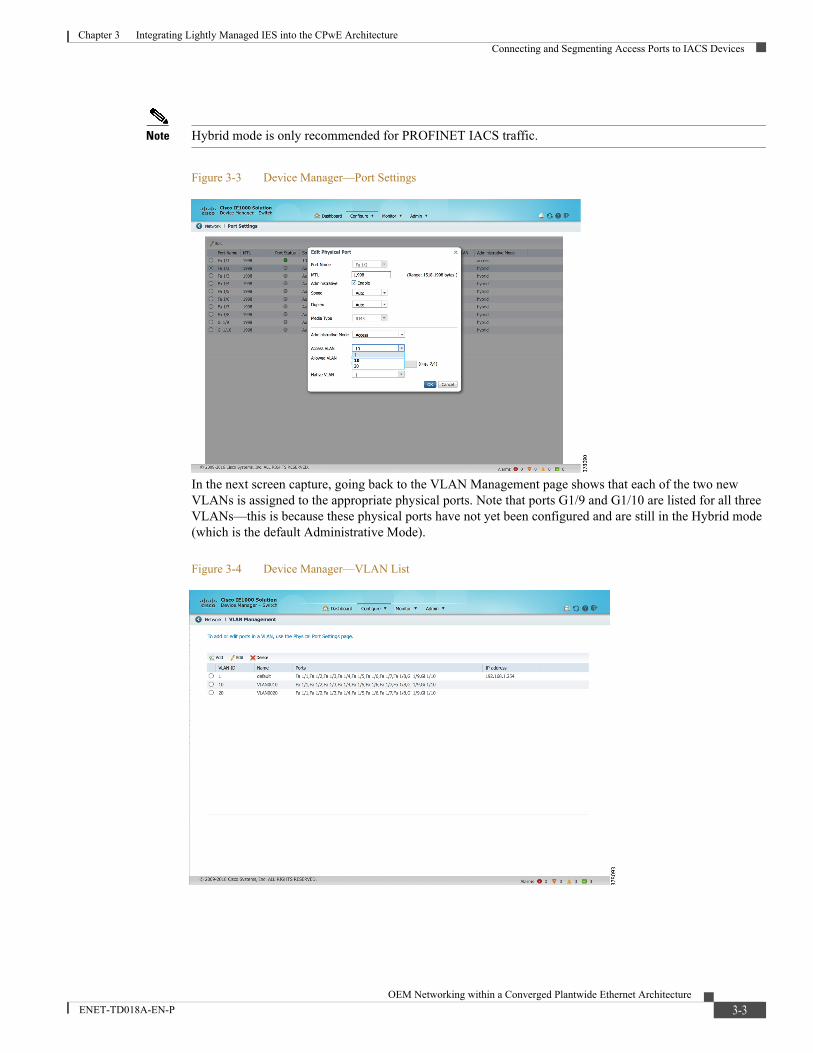
Note Hybrid mode is only recommended for PROFINET IACS traffic.
Figure 3-3 Device Manager—Port Settings
In the next screen capture, going back to the VLAN Management page shows that each of the two new VLANs is assigned to the appropriate physical ports. Note that ports G1/9 and G1/10 are listed for all three VLANs—this is because these physical ports have not yet been configured and are still in the Hybrid mode (which is the default Administrative Mode).
Figure 3-4 Device Manager—VLAN List
3-3OEM Networking within a Converged Plantwide Ethernet Architecture
ENET-TD018A-EN-P
Chapter 3 Integrating Lightly Managed IES into the CPwE ArchitectureVLANs Trunked to Upstream Fully Managed IES
VLANs Trunked to Upstream Fully Managed IESIn order for the lightly managed IES to forward traffic for all of its VLANs to upstream fully managed IES over a single physical port, a trunk is used. This trunk maintains separation of the VLANs by tagging each frame with an IEEE 802.1Q VLAN ID. When the fully managed IES receives a frame with the tagged VLAN ID, it is able to determine to which VLAN the frame should be forwarded.
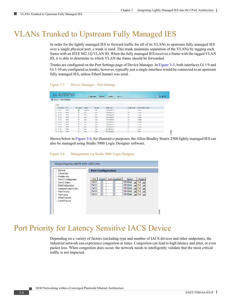
Trunks are configured on the Port Settings page of Device Manager. In Figure 3-5, both interfaces Gi 1/9 and Gi 1/10 are configured as trunks; however, typically just a single interface would be connected to an upstream fully managed IES, unless EtherChannel was used.
Figure 3-5 Device Manager—Port Settings
Shown below in Figure 3-6, for illustrative purposes, the Allen-Bradley Stratix 2500 lightly managed IES can also be managed using Studio 5000 Logix Designer software.
Figure 3-6 Management via Studio 5000 Logix Designer
Port Priority for Latency Sensitive IACS DeviceDepending on a variety of factors (including type and number of IACS devices and other endpoints), the industrial network can experience congestion at times. Congestion can lead to high latency and jitter, or even packet loss. When congestion does occur, the network needs to intelligently validate that the most critical traffic is not impacted.
3-4OEM Networking within a Converged Plantwide Ethernet Architecture
ENET-TD018A-EN-P

Chapter 3 Integrating Lightly Managed IES into the CPwE ArchitecturePort Priority for Latency Sensitive IACS Device
Lightly managed IES support basic QoS for prioritizing important traffic that is not tolerant of latency, jitter or packet loss. QoS is implemented on the switches in the form of a port priority feature that is accessed by navigating to Configure > QoS. The port priority is simply configured by selecting one (or more) interfaces and then checking the Enable check box. In this example, an IACS device that is not tolerant of packet loss or latency is connected to port Fa 1/2.
Figure 3-7 Device Manager - QoS
By default, the lightly managed IES will trust DSCP and COS markings on ingress frames, and will not re-write the markings on egress, unless the egress interface has port priority enabled. With port priority enabled, the lightly managed IES re-marks ingress frames with DSCP = 24 and COS = 3, no matter the original marking.
The lightly managed IES has eight egress queues using strict priority scheduling algorithm, meaning a fixed mapping exists between the DSCP/COS markings and the egress queue.
Table 3-1 COS to Egress Queue Mapping
COS Value Egress Queue (7 is highest priority)
1 0
0 1
2 2
3 3
4 4
5 5
6 6
7 7
Table 3-2 DSCP to Egress Queue Mapping
DSCP Value Range DSCP Name Egress Queue (7 is highest priority)
8-15 CS1 0
0-7 CS0 1
10-14 AF11 - AF13
16-23 CS2 2
18-22 AF21 - AF23
24-31 CS3 3
26-30 AF31 - AF33
32-39 CS4 4
34-38 AF41 - AF43
40-45, 47 CS5 5
3-5OEM Networking within a Converged Plantwide Ethernet Architecture
ENET-TD018A-EN-P
Chapter 3 Integrating Lightly Managed IES into the CPwE ArchitectureLayer 2 NAT on Managed IES
The Port Priority feature should only be enabled on one, or possibly two, of the ports of the switch—those connected to critical devices that are not tolerant of latency, jitter or loss. If the feature is enabled on all ports, all ports will have the same priority, thus negating the intended benefit.
Layer 2 NAT on Managed IESAs shown in Figure 1-5, the lightly managed IES is connected to an upstream fully managed IES with NAT capability. In this example, the process skid containing the lightly managed IES and attached IACS devices is one of many such sub-zones. To simplify the network design and configuration, duplicate IP addressing is used in all of the sub-zones—192.168.10.x/24 and 192.168.20.x exist in multiple locations in the plant. In order for IACS devices in multiple sub-zones to coexist with overlapping IP addresses, network address translation (with multiple instances of NAT, on a per-VLAN basis) is configured on the upstream fully managed IES. This allows the overlapping addresses to be statically mapped to unique "outside" IP addresses reachable throughout the plant.
More information on “Deploying Network Address Translation within a Converged Plantwide Ethernet Architecture” can be found at the following URLs:
• Rockwell Automation site:
– http://literature.rockwellautomation.com/idc/groups/literature/documents/td/enet-td007_-en-p.pdf
• Cisco site:
– https://www.cisco.com/c/en/us/td/docs/solutions/Verticals/CPwE/3-5-1/NAT/DIG/CPwE_NAT_CVD.pdf
48-55 CS6 6
46, 56-63 EF CS7 7
Table 3-2 DSCP to Egress Queue Mapping (continued)
DSCP Value Range DSCP Name Egress Queue (7 is highest priority)
3-6OEM Networking within a Converged Plantwide Ethernet Architecture
ENET-TD018A-EN-P

OEM Networking within a Con
ENET-TD018A-EN-P
C H A P T E R 4
ValidationThis chapter, which documents the testing performed on the lightly managed IES, includes the following major topics:
• System Validation Coverage, page 4-1
• System Validation Results, page 4-2
The scope of the validation for this CRD is limited compared to the extensive Cisco Validated Design process typically performed by the Cisco and Rockwell Automation subject matter authorities. The scope of testing is more narrowly focused on the lightly managed IES itself, and to a limited degree, the directly attached devices. All testing was performed in the full CPwE test lab which is a comprehensive end-to-end architecture, and the testing documented here should be viewed as an extension to the existing collection of CPwE architectures.
System Validation CoverageTest coverage of the lightly managed IES was divided into the four areas described below:
• Manageability—Configuration and validation of all basic features of the lightly managed IES via the web based GUI, including port settings, VLANs, EtherChannel and MSTP.
• Connectivity—Validate basic connectivity through the lightly managed IES, including ping (ICMP), CIP IACS device discovery and multicast.
• Availability—Validate MSTP convergence time, EtherChannel member link failure and QoS Priority Port feature.
• Security—Validate basic security related features including SSH access to CLI for troubleshooting and port security. Note that the CLI is limited to read-only operations for troubleshooting purposes—all configuration is done through the graphical Device Manager interface.
4-1verged Plantwide Ethernet Architecture
Chapter 4 ValidationSystem Validation Results
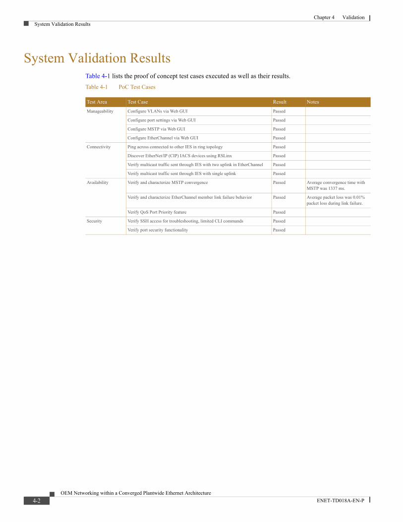
System Validation ResultsTable 4-1 lists the proof of concept test cases executed as well as their results.
Table 4-1 PoC Test Cases
Test Area Test Case Result Notes
Manageability Configure VLANs via Web GUI Passed
Configure port settings via Web GUI Passed
Configure MSTP via Web GUI Passed
Configure EtherChannel via Web GUI Passed
Connectivity Ping across connected to other IES in ring topology Passed
Discover EtherNet/IP (CIP) IACS devices using RSLinx Passed
Verify multicast traffic sent through IES with two uplink in EtherChannel Passed
Verify multicast traffic sent through IES with single uplink Passed
Availability Verify and characterize MSTP convergence Passed Average convergence time with MSTP was 1337 ms.
Verify and characterize EtherChannel member link failure behavior Passed Average packet loss was 0.01% packet loss during link failure.
Verify QoS Port Priority feature Passed
Security Verify SSH access for troubleshooting, limited CLI commands Passed
Verify port security functionality Passed
4-2OEM Networking within a Converged Plantwide Ethernet Architecture
ENET-TD018A-EN-P
OEM Networking within a Co
ENET-TD018A-EN-P
A P P E N D I X A
ReferencesThe following documents and websites are relevant to the OEM Networking within a Converged Plantwide Ethernet Architecture CRD:
• Cisco Industrial Ethernet 1000 Series Switches Data Sheet at the following URL:
– http://www.cisco.com/c/en/us/products/collateral/switches/industrial-ethernet-1000-series-switches/datasheet-c78-737277.html?cachemode=refresh
• Release Notes for the Industrial Ethernet 1000 Series Switch (Software Release 1.6) at the following URL:
– https://www.cisco.com/c/en/us/td/docs/switches/lan/cisco_ie1000/release_notes/b_ie1k_Strat2500_1-6rn.html
• Design Zone for Manufacturing—Converged Plantwide Ethernet at the following URL:
– http://www.cisco.com/c/en/us/solutions/enterprise/design-zone-manufacturing/landing_ettf.html
• Industrial Network Architectures—Converged Plantwide Ethernet at the following URL:
– http://www.rockwellautomation.com/global/capabilities/industrial-networks/overview.page?pagetitle=Network-Architectures
• Stratix 2500 Lightly Managed Switches at the following URL:
– http://ab.rockwellautomation.com/Networks-and-Communications/Stratix-2500-Lightly-Managed
• Stratix Ethernet Device Specifications (Technical Data) at the following URL:
– http://literature.rockwellautomation.com/idc/groups/literature/documents/td/1783-td001_-en-p.pdf
• The OEM Guide to Networking at the following URL:
– http://literature.rockwellautomation.com/idc/groups/literature/documents/rm/enet-rm001_-en-p.pdf
A-1nverged Plantwide Ethernet Architecture
OEM Networking within a Co
ENET-TD018A-EN-P
A P P E N D I X B
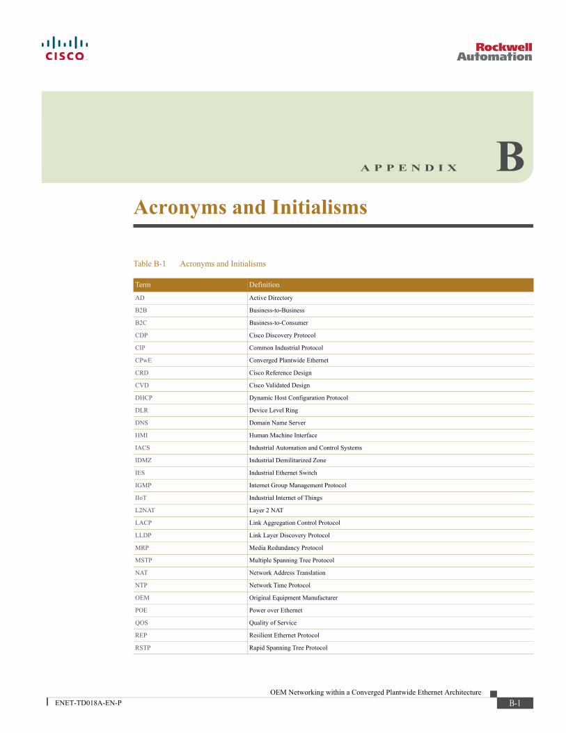
Acronyms and InitialismsTable B-1 Acronyms and Initialisms
Term Definition
AD Active Directory
B2B Business-to-Business
B2C Business-to-Consumer
CDP Cisco Discovery Protocol
CIP Common Industrial Protocol
CPwE Converged Plantwide Ethernet
CRD Cisco Reference Design
CVD Cisco Validated Design
DHCP Dynamic Host Configuration Protocol
DLR Device Level Ring
DNS Domain Name Server
HMI Human Machine Interface
IACS Industrial Automation and Control Systems
IDMZ Industrial Demilitarized Zone
IES Industrial Ethernet Switch
IGMP Internet Group Management Protocol
IIoT Industrial Internet of Things
L2NAT Layer 2 NAT
LACP Link Aggregation Control Protocol
LLDP Link Layer Discovery Protocol
MRP Media Redundancy Protocol
MSTP Multiple Spanning Tree Protocol
NAT Network Address Translation
NTP Network Time Protocol
OEM Original Equipment Manufacturer
POE Power over Ethernet
QOS Quality of Service
REP Resilient Ethernet Protocol
RSTP Rapid Spanning Tree Protocol
B-1nverged Plantwide Ethernet Architecture

Appendix B Acronyms and Initialisms
SNMP Simple Network Management Protocol
STP Spanning Tree Protocol
SVI Switched Virtual Interface
VLAN Virtual Local Area Networks
Table B-1 Acronyms and Initialisms (continued)
Term Definition
B-2OEM Networking within a Converged Plantwide Ethernet Architecture
ENET-TD018A-EN-P
OEM Networking within a Co
ENET-TD018A-EN-P
A P P E N D I X C
About the Cisco Validated Design (CVD) ProgramConverged Plantwide Ethernet (CPwE) is a collection of tested and validated architectures developed by subject matter authorities at Cisco and Rockwell Automation which follows the Cisco Validated Design (CVD) program.
CVDs provide the foundation for systems design based on common use cases or current engineering system priorities. They incorporate a broad set of technologies, features, and applications to address customer needs. Each one has been comprehensively tested and documented by engineers to ensure faster, more reliable, and fully predictable deployment.
The CVD process is comprehensive and focuses on solving business problems for customers and documenting these solutions. The process consists of the following steps:
1. Requirements are gathered from a broad base of customers to devise a set of use cases that will fulfill these business needs.
2. Network architectures are designed or extended to provide the functionality necessary to enable these use cases, and any missing functionality is relayed back to the appropriate product development team(s).
3. Detailed test plans are developed based on the architecture designs to validate the proposed solution, with an emphasis on feature and platform interaction across the system. These tests generally consist of functionality, resiliency, scale, and performance characterization.
4. All parties contribute to the development of the CVD guide, which covers both design recommendations and implementation of the solution based on the testing outcomes.
Within the CVD program, CPwE also provides Cisco Reference Designs (CRDs) that follow the CVD process but focus on reference designs developed around specific set of priority use cases. The scope of CRD testing typically focuses on solution functional verification with limited scale.
For more information about the CVD program, please see Cisco Validated Designs at the following URL:
• https://www.cisco.com/c/en/us/solutions/enterprise/validated-design-program/index.html
C-1nverged Plantwide Ethernet Architecture

Appendix C About the Cisco Validated Design (CVD) Program
Cisco is the worldwide leader in networking that transforms how people connect, communicate and collaborate. Information about Cisco can be found at www.cisco.com. For ongoing news, please go to http://newsroom.cisco.com. Cisco equipment in Europe is supplied by Cisco Systems International BV, a wholly owned subsidiary of Cisco Systems, Inc.
www.cisco.com
Americas HeadquartersCisco Systems, Inc.San Jose, CA
Asia Pacific HeadquartersCisco Systems (USA) Pte. Ltd.Singapore
Europe HeadquartersCisco Systems International BVAmsterdam, The Netherlands
Cisco has more than 200 offices worldwide. Addresses, phone numbers, and fax numbers are listed on the Cisco Website at www.cisco.com/go/offices.
Cisco and the Cisco logo are trademarks or registered trademarks of Cisco and/or its affiliates in the U.S. and other countries. To view a list of Cisco trademarks, go to this URL: www.cisco.com/go/trademarks. Third-party trademarks mentioned are the property of their respective owners. The use of the word partner does not imply a partnership relationship between Cisco and any other company. (1721R)
Rockwell Automation is a leading provider of power, control and information solutions that enable customers to get products to market faster, reduce their total cost of ownership, better utilize plant assets, and minimize risks in their manufacturing environments.
www.rockwellautomation.com
Americas:Rockwell Automation1201 South Second Street Milwaukee, WI 53204-2496 USA Tel: (1) 414.382.2000, Fax: (1) 414.382.4444
Asia Pacific:Rockwell AutomationLevel 14, Core F, Cyberport 3 100 Cyberport Road, Hong Kong Tel: (852) 2887 4788, Fax: (852) 2508 1846
Europe/Middle East/Africa: Rockwell AutomationVorstlaan/Boulevard du Souverain 36 1170 Brussels, Belgium Tel: (32) 2 663 0600, Fax: (32) 2 663 0640
Allen-Bradley, Rockwell Automation, Stratix, Studio 5000 Logix Designer and RSLinx are trademarks of Rockwell Automation, Inc. Trademarks not belonging to Rockwell Automation are property of their respective companies.
EtherNet/IP and CIP are trademarks of ODVA, Inc..
© 2017 Cisco Systems, Inc. and Rockwell Automation, Inc. All rights reserved.
Publication ENET-TD018A-EN-P October 2017
Related Documents