www.femp.energy.gov Ocean Energy Technology Overview Prepared for the U.S. Department of Energy Office of Energy Efficiency and Renewable Energy Federal Energy Management Program July 2009 DOE/GO-102009-2823

Welcome message from author
This document is posted to help you gain knowledge. Please leave a comment to let me know what you think about it! Share it to your friends and learn new things together.
Transcript
www.femp.energy.gov
Ocean Energy Technology Overview
Prepared for the U.S. Department of Energy Office of Energy Efficiency and Renewable Energy Federal Energy Management Program
July 2009 DOE/GO-102009-2823
Ocean Energy Technology Overview i
Contacts Principal Investigators: Kari Burman Phone: 303-384-7558 E-mail: [email protected] Andy Walker, PhD PE Phone: 303-384-7531 E-mail: [email protected] Energy Management and Federal Markets Group National Renewable Energy Laboratory (NREL) MS 301 1617 Cole Boulevard Golden, CO 80401 Sponsor: U.S. Department of Energy Federal Energy Management Program Acknowledgements This work was sponsored by the U.S. Department of Energy (DOE) Federal Energy Management Program (FEMP). Research regarding ocean energy resources, status of wave and tidal power technologies, and ocean thermal energy conversion (OTEC) technologies was provided by Andy Walker, Walt Musial, and Desikan Bharathan at the National Renewable Energy Laboratory (NREL). Carol Fitzgerald, NREL Librarian, provided research assistance. Kari Burman of NREL conducted research and prepared the report.
Ocean Energy Technology Overview ii
Executive Summary This paper presents an overview of ocean energy technology as a source of renewable energy for U.S. Federal sites. It investigates ocean energy resources and new technologies under development to capture that energy. These technologies span:
• Wave energy • Tidal energy • Marine current energy • Ocean thermal energy conversion (OTEC)
A brief history of the technologies is presented, as well as each technology’s commercial market development status. Benefits and barriers to research and development are also examined along with various devices currently being validated in the field. Significant growth has occurred in the number of devices developed for ocean energy conversion since 2003. Multiple countries are now becoming involved in technology research and development. As many of these technologies near commercial deployment, some governments are proposing market support policies to reduce the current cost gap and help accelerate the rate of commercialization. Ocean energy resources are significant around the United States. New energy conversion devices could help alleviate U.S. dependency on foreign oil while reducing Federal Government utility costs. Federal sites should take this opportunity to consider ocean energy development to generate renewable energy and help meet Federal mandates, such as the Energy Policy Act of 2005 (EPAct 2005) and the Energy Independence and Security Act of 2007 (EISA 2007). In general, Federal research and development funding for ocean energy technologies is increasing. There are several projects being sponsored by the Navy and other Federal entities. Support from national laboratories in testing new devices may help greatly in demonstrating design concepts and reliability of new devices. As long as progress is being made in the development of ocean energy technologies, the increasing trend in Federal expenditures is likely to continue to rise. At the time of this report, few full scale commercialized ocean energy conversion systems have been tied to the grid. A number of small prototypes are being tested, primarily in wave and marine current technologies, and this number is growing. Technical and financial support from governments across the globe may be crucial in moving new ocean energy technology from prototype to commercially viable product.
Ocean Energy Technology Overview iii
Table of Contents
Executive Summary ii
1 Ocean Energy 4
1.1 Introduction 4 1.2 Background 4 1.3 Technology Types 5 1.4 Resources 5 1.5 Benefits 8 1.6 Barriers 8
2 Wave Energy 10
2.1 Overview 10 2.2 Resources 10 2.3 Energy Conversion Technologies 10
3 Tidal and Marine Current Energy 16
3.1 Overview 16 3.2 Resources 16 3.3 Energy Conversion Technologies 17
4 Ocean Tidal Energy 22
4.1 Overview 22 4.2 Resources 22 4.3 Energy Conversion Technologies 22
5 Ocean Thermal Energy Conversion 24
5.1 Overview 24 5.2 Resources 24 5.3 Energy Conversion Technologies 24
6 Conclusion 28
6.1 Development Summary 28
References 30
Ocean Energy Technology Overview 4
1 Ocean Energy 1.1 Introduction The Department of Energy’s (DOE) Federal Energy Management Program (FEMP) facilitates the Federal Government’s implementation of sound, cost-effective energy management and investment practices to enhance the nation’s energy security and environmental stewardship. FEMP works to reduce the cost and environmental impact of the Federal Government by advancing energy efficiency and promoting the use of distributed and renewable energy at Federal sites. The overall goal is to lower Federal fossil-fuel energy consumption to reduce environmental and national security risks. This goal is supported by renewable energy and energy efficiency mandates as set forth in the Energy Policy Act of 2005 (EPAct 2005), Energy Independence and Security Act of 2007 (EISA 2007), and other Federal regulations. Oceans cover 70 percent of the earth’s surface and represent an enormous amount of energy in the form of wave, tidal, marine current, and thermal resources. Though ocean energy is still in a developmental stage, researchers are seeking ways to capture that energy and convert it to electricity. EPAct 2005 provides the Department of the Interior (DOI) leasing authority to support production, transportation, and transmission of energy off the Outer Continental Shelf. This leasing authority provides jurisdiction over projects that produce alternative energy and can make use of existing oil and gas platforms in Federal waters. Marine technology was once considered too expensive to be a viable source of alternative clean energy, especially compared to already developed products such as wind and solar. However, with the increased price of oil and the issues of global warming and national security, U.S. coastal sites are looking to add ocean energy to their renewable energy portfolios. This paper gives an overview of ocean energy technologies, focusing on four different types: wave, tidal, marine current, and ocean thermal energy conversion (OTEC). It outlines the operating principles, the status, and the efficiency and cost of generating energy associated with each technology. 1.2 Background Ocean and marine energy refers to various forms of renewable electric energy harnessed from the ocean. There are two primary types of ocean energy: mechanical and thermal. The rotation of the earth and the moon’s gravitational pull create mechanical forces. The rotation of the earth creates wind on the ocean surface that forms waves, while the gravitational pull of the moon creates coastal tides and currents. Thermal energy is derived from the sun, which heats the surface of the ocean while the depths remain colder. This temperature difference allows energy to be captured and converted to electric power.
People have been fascinated with capturing ocean energy since the late 18th century. Monsieur Girard received the first recorded patent for wave energy conversion in 1799. The patented device consisted of a ship attached to shore with waves driving pumps and other machinery. Only occasional attempts to harness the ocean’s energy were made between 1800 and the late 1960’s. However, in 1966, the largest tidal power station in the world was built in St. Malo, France [1]. This ocean tidal power station still operates today, producing 240 megawatt-hours (MWh) of power each year.
Widespread attempts to harness ocean energy wax and wane with the price of oil. In 1973, an oil shortage crisis occurred when the Organization of Petroleum Exporting Countries (OPEC) placed an embargo on shipments of oil to the U.S. and Europe. During that time, an engineer from Scotland, Stephen Salter, took the first steps to develop an ocean-wave generator known as Salter’s Duck. The duck moves up and down with wave motion. A turbine converts this movement to electrical energy. This single wave-conversion device produced six megawatts (MW) of electricity at a cost of nearly $1 per kilowatt-hour (kWh). The initial cost of wave power was considered too high, and the Salter Duck never made it to production [2].
With fossil fuel prices increasing and expected to stay high in the future, the search for alternative energy resources is once again on the forefront. In the past few years, a growing interest emerged in ocean energy, and progress is being made to bring ocean energy technologies from development stages to the commercial market.
Ocean Energy Technology Overview 5
1.3 Technology Types Four types of ocean energy conversion exist: wave energy, tidal energy, marine current energy, and ocean thermal energy conversion.
Wave Energy Wave energy is generated by the movement of a device either floating on the surface of the ocean or moored to the ocean floor. Many different techniques for converting wave energy to electric power have been studied.
Wave conversion devices that float on the surface have joints hinged together that bend with the waves. This kinetic energy pumps fluid through turbines and creates electric power. Stationary wave energy conversion devices use pressure fluctuations produced in long tubes from the waves swelling up and down. This bobbing motion drives a turbine when critical pressure is reached. Other stationary platforms capture water from waves on their platforms. This water is allowed to runoff through narrow pipes that flow through a typical hydraulic turbine.
Wave energy is proving to be the most commercially advanced of the ocean energy technologies with a number of companies competing for the lead.
Tidal Energy The tidal cycle occurs every 12 hours due to the gravitational force of the moon. The difference in water height from low tide and high tide is potential energy.
Similar to traditional hydropower generated from dams, tidal water can be captured in a barrage across an estuary during high tide and forced through a hydro-turbine during low tide. To capture sufficient power from the tidal energy potential, the height of high tide must be at least five meters (16 feet) greater than low tide. There are only approximately 20 locations on earth with tides this high. The Bay of Fundy between Maine and Nova Scotia features the highest tides in the world, reaching 17 meters (56 feet). This area has the potential to produce 10,000 MW [3].
Current Energy Marine current is ocean water moving in one direction. In the U.S., it is found primarily off the coast of Florida. This ocean current is known as the Gulf Stream. Tides also create currents that flow in two directions. Kinetic energy can be captured from the Gulf Stream and other tidal currents with submerged turbines that are very similar in appearance to miniature wind turbines. As with wind turbines, the constant movement of the marine current moves the rotor blades to generate electric power.
Ocean Thermal Energy Conversion Ocean thermal energy conversion, or OTEC, uses ocean temperature differences from the surface to depths lower than 1,000 meters, to extract energy. A temperature difference of only 20°C (36°F) can yield usable energy.
Research focuses on two types of OTEC technologies to extract thermal energy and convert it to electric power: closed cycle and open cycle. In the closed cycle method, a working fluid, such as ammonia, is pumped through a heat exchanger and vaporized. This vaporized steam runs a turbine. The cold water found at the depths of the ocean condenses the vapor back to a fluid where it returns to the heat exchanger. In the open cycle system, the warm surface water is pressurized in a vacuum chamber and converted to steam to run the turbine. The steam is then condensed using cold ocean water from lower depths [3].
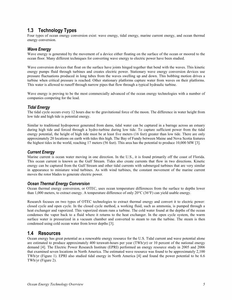
1.4 Resources Ocean energy has great potential as a renewable energy resource for the U.S. Tidal current and wave potential alone are estimated to produce approximately 400 terawatt-hours per year (TWh/yr) or 10 percent of the national energy demand [4]. The Electric Power Research Institute (EPRI) performed an energy resource study in 2005 and 2006 that examined seven locations in North America. The estimated wave resource was found to be approximately 2,100 TWh/yr (Figure 1). EPRI also studied tidal energy in North America [4] and found the power potential to be 6.6 TWh/yr (Figure 2).
Ocean Energy Technology Overview 6
Figure 1: Preliminary Estimate of U.S. Coastal Wave Energy Resources (60-meter Depth and Greater than 10 kW/m) Courtesy of the Electric Power Research Institute
New England / Mid- Atlantic 110 TWh/yr Hawaii
330 TWh/yr
WA, OR, and CA 440 TWh/yr
Alaska 1,250 TWh/yr
Ocean Energy Technology Overview 7
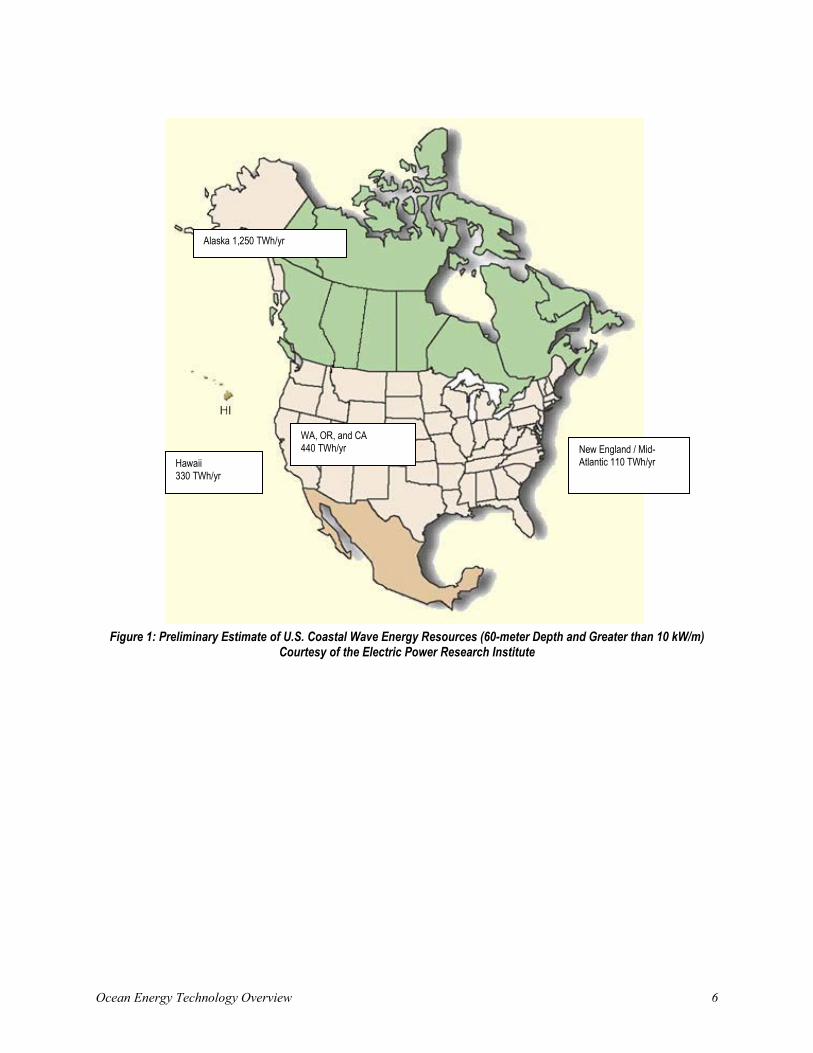
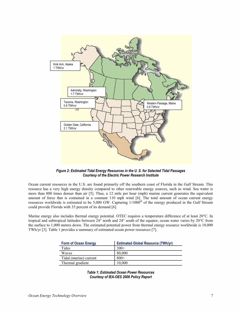
Figure 2: Estimated Tidal Energy Resources in the U. S. for Selected Tidal Passages Courtesy of the Electric Power Research Institute
Ocean current resources in the U.S. are found primarily off the southern coast of Florida in the Gulf Stream. This resource has a very high energy density compared to other renewable energy sources, such as wind. Sea water is more than 800 times denser than air [5]. Thus, a 12 mile per hour (mph) marine current generates the equivalent amount of force that is contained in a constant 110 mph wind [6]. The total amount of ocean current energy resources worldwide is estimated to be 5,000 GW. Capturing 1/1000th of the energy produced in the Gulf Stream could provide Florida with 35 percent of its demand [6]. Marine energy also includes thermal energy potential. OTEC requires a temperature difference of at least 20°C. In tropical and subtropical latitudes between 24° north and 24° south of the equator, ocean water varies by 20°C from the surface to 1,000 meters down. The estimated potential power from thermal energy resource worldwide is 10,000 TWh/yr [3]. Table 1 provides a summary of estimated ocean power resources [7].
Form of Ocean Energy Estimated Global Resource (TWh/yr) Tides 300+ Waves 80,000 Tidal (marine) current 800+ Thermal gradient 10,000
Table 1: Estimated Ocean Power Resources
Courtesy of IEA-OES 2006 Policy Report
Western Passage, Maine 0.9 TWh/yr
Golden Gate, California 2.1 TWh/yr
Tacoma, Washington 0.9 TWh/yr
Admiralty, Washington 1.7 TWh/yr
Knik Arm, Alaska 1 TWh/yr
Ocean Energy Technology Overview 8
1.5 Benefits The increasing price of oil and fossil fuels along with the growing concerns of global warming has sparked interest in renewable energy in the U.S. and around the world. The search for clean, sustainable energy to generate electricity is again in the forefront of the news, and the race to develop ocean power at a competitive price is important.
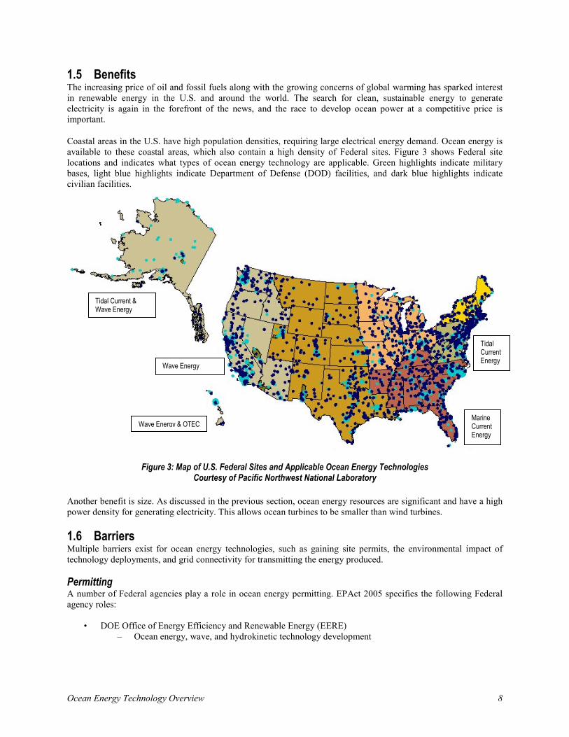
Coastal areas in the U.S. have high population densities, requiring large electrical energy demand. Ocean energy is available to these coastal areas, which also contain a high density of Federal sites. Figure 3 shows Federal site locations and indicates what types of ocean energy technology are applicable. Green highlights indicate military bases, light blue highlights indicate Department of Defense (DOD) facilities, and dark blue highlights indicate civilian facilities.
Figure 3: Map of U.S. Federal Sites and Applicable Ocean Energy Technologies Courtesy of Pacific Northwest National Laboratory
Another benefit is size. As discussed in the previous section, ocean energy resources are significant and have a high power density for generating electricity. This allows ocean turbines to be smaller than wind turbines.
1.6 Barriers Multiple barriers exist for ocean energy technologies, such as gaining site permits, the environmental impact of technology deployments, and grid connectivity for transmitting the energy produced. Permitting A number of Federal agencies play a role in ocean energy permitting. EPAct 2005 specifies the following Federal agency roles:
• DOE Office of Energy Efficiency and Renewable Energy (EERE) – Ocean energy, wave, and hydrokinetic technology development
Tidal Current & Wave Energy
Tidal Current Energy Wave Energy
Wave Energy & OTEC
Marine Current Energy
Ocean Energy Technology Overview 9
• DOI Minerals Management Service (MMS) – Designated lead agency to permit non-extractive energy facilities (including waves on the Outer
Continental Shelf) – Siting activities in collaboration with the DOD
• Corps of Engineers
– Navigation obstructions in Federal water ways (Section 10 Permit) – Water quality and approval of most transmission lines
• Federal Energy Regulatory Commission (FERC)
– Power supply contract approvals – Defined powerhouse under Federal Powers Act of 2003 for wave and tidal
• National Oceanic and Atmospheric Administration (NOAA)
– Siting in and around protected areas (marine sanctuaries) – Specific legislation for OTEC (not active)
Permitting and obtaining Federal approval to install ocean energy projects can be cumbersome. Permitting is one of the key factors delaying the deployment of ocean energy. Progress has been made to allow the pilot testing of new technologies on a smaller scale before going through the full permitting process. Environmental Impact Marine technologies are new, unproven, and their cumulative environmental impacts are not known [8]. Though ocean energy systems are expected to have little negative impact on the environment, the technologies are too new to gauge all factors. Prolonged studies are needed. Transmission Lines Availability of transmission lines impacts how fast ocean energy can be commercialized. Planning for upgrades with utility companies should be a part of overall ocean energy projects.
Ocean Energy Technology Overview 10
2 Wave Energy 2.1 Overview Wave energy is captured by devices that are stationary or move up and down with the frequency of waves. Energy conversion devices also capture waves in reservoirs by overtopping the device and channeling sea water through a hydro turbine to generate electricity. Wave height and frequency determine wave energy. Section 2.3 discusses categories of wave technology and current technology development in more detail.
2.2 Resources
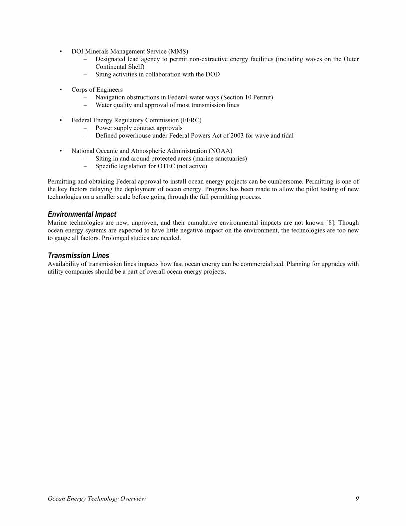
Figure 4 maps the kilowatt per meter (kW/m) crest length of wave energy around global coastlines. The crest length is measured from one crest, or peak, to the next.
Note that wave energy increases as latitudes increase north or south. Latitudes greater than 40° generate the highest energy. The largest wave energy in the U.S. is found in Alaska, reaching 67 kW/m. Conversely, there is virtually no wave energy in the Gulf Coast.
Figure 4: Wave Energy Levels in kW/m Crest Length Courtesy of the European Ocean Energy Association
2.3 Energy Conversion Technologies Wave energy technology is rapidly growing and varies widely in application of conversion devices. Energy conversion devices can be situated on or off shore. Four categories of wave energy technology exist: attenuators, point absorbers, overtopping terminators, and oscillating wave column (OWC) terminators. Point absorbers and attenuators capture wave energy as they are placed in the path of the wave. Attenuators are situated parallel to the waves and energy is captured over the surface area. Point absorbers are moored to the sea bed or float near the surface, collecting wave energy from all directions. Terminators restrain wave motion and capture energy through long arms. OWC terminators capture water from an opening into a partially submerged platform and let that water rise in an air column. The air is compressed, which drives a turbine to generate electricity. Table 2 outlines devices, applications, and projects in development for each wave energy technology.
Hawaii 10-15 kW/m
Ocean Energy Technology Overview 11
Table 2: Wave Energy Technology
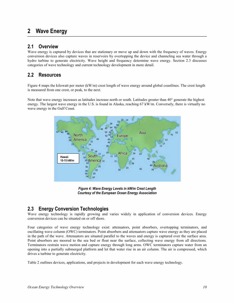
Company: AWS Ocean Energy Product Name: Archimedes Waveswing Product Website: http://www.awsocean.com
Technology - Point Absorber: Developed in 2004, this device is a buoy moored to the seabed. Waves move over a submerged air-filled upper casing and push against the fixed cylinder. Air inside the cylinder is compressed, serving as a point absorber. The compressed air drives a hydraulic system and generator set to convert the wave energy to electricity.
Projects: Pilot power plant installed off the coast of Portugal in 2004. Power plant in Portugal was designed to test technology at full scale but was not designed as a long-term demonstrator. Pre-commercial 250 kW device is planned for testing during 2009 and 2010 at Orkney’s European Marine Energy Center (EMEC) in Scotland.
Test Performance: Pilot plant delivered wave power to the Portuguese grid at predicted levels (250 kW). Pre-commercial 250 kW prototype to be tested in Scotland (EMEC). The technology is scalable and the commercial system will be in excess of 1 MW.
Figure 5: Archimedes Waveswing Courtesy of AWS Ocean Energy
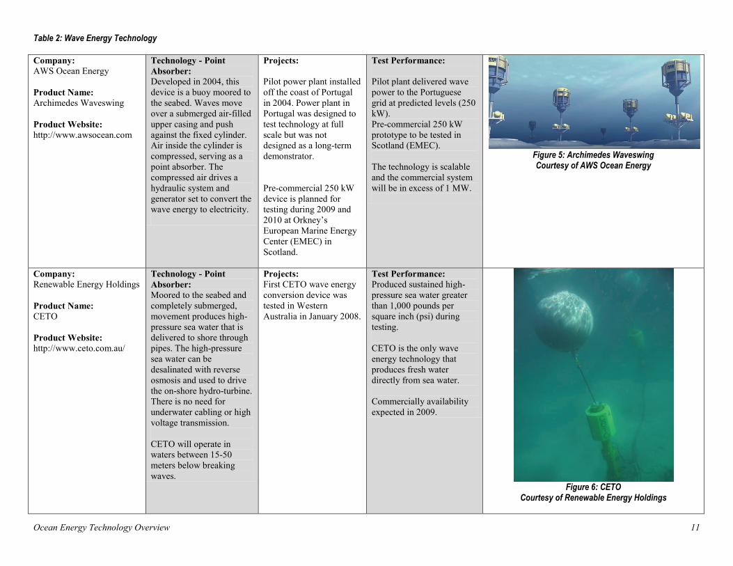
Company: Renewable Energy Holdings Product Name: CETO Product Website: http://www.ceto.com.au/
Technology - Point Absorber: Moored to the seabed and completely submerged, movement produces high-pressure sea water that is delivered to shore through pipes. The high-pressure sea water can be desalinated with reverse osmosis and used to drive the on-shore hydro-turbine. There is no need for underwater cabling or high voltage transmission. CETO will operate in waters between 15-50 meters below breaking waves.
Projects: First CETO wave energy conversion device was tested in Western Australia in January 2008.
Test Performance: Produced sustained high-pressure sea water greater than 1,000 pounds per square inch (psi) during testing. CETO is the only wave energy technology that produces fresh water directly from sea water. Commercially availability expected in 2009.
Figure 6: CETO
Courtesy of Renewable Energy Holdings

Ocean Energy Technology Overview 12
Company: Pelamis Wave Power (PWP)* Product Name: Pelamis Product Website: http://www.pelamis wave.com *Formerly Ocean Power Delivery
Technology - Attenuator: Semi-submerged structure composed of cylindrical sections linked by hydraulic joints. Ram pumps resist wave motion in the joints that in turn pump high-pressure oil through motors. The hydraulic motors drive generators to produce electricity. Each device is 140 meters long and 3.5 meters in diameter with three wave energy conversion modules.
Projects: PWP is working on three full scale trials with the initial one deployed in Portugal summer 2008: 2.25 MW Agucadoura wave project off the coast of Portugal for Enersis and Babcock & Brown. 3 MW project under development off the coast of Orkney for Scottish Power Renewables. 5 MW wave station for Cornwall, United Kingdom, as part of the Cornwall Wave Hub.
Test Performance: The multiple PWP units in Agucadoura make up the world’s first multi-unit commercial wave farm tied to Portuguese grid. Each Pelamis is capable of generating 750 kW with an expected average of 25-40% of this power being continuously generated. Cost: Estimated (2004) $2 million to $3 million per device.
Figure 7: Pelamis
Courtesy of Pelamis Wave Power
Company: Finavera Renewables* Product Name: AquaBuoy Product Website: http://www.finavera.com *Formerly AquaEnergy
Technology - Point Absorber: A moored buoy floats on the surface of the waves. As the buoy moves up and down, sea water inside a 25-meter (82-foot) tube drives a piston that then drives a hose pump. Sea water inside the elongated hose becomes pressurized and is released to drive the Pelton turbine. Underwater transmission lines transmit electric energy to shore. The AquaBuoy must be deployed where water depth is greater than 50 meters (164 feet).
Projects: 1 MW project in Makah Bay, Washington, pending a FERC environmental impact study. 2 MW project with 200 MW planned for Figueira de Foz, Portugal. 5 MW wave energy device off Ucluelet, British Columbia, granted an investigative permit. 20 MW wave energy project off Western Cape, South Africa. 200 MW wave park under development in Coos Bay, Oregon. FERC granted a preliminary permit for this project.
Test Performance: Each 40-ton AquaBuoy is rated for up to 250 kW. Unfortunately, the prototype device failed before power tests were complete, springing a leak that caused the pump to malfunction after only one month of deployment. The AquaBuoy sank off the coast of Oregon. The test was intended to measure power output of the AquaBuoy 2.0. No reports from this test have been released. Cost: The cost for the project in Makah Bay, Washington, including grid connection cable and four AquaBuoys, was $3 million (2004).
Figure 8: AquaBuoy
Courtesy of Finavera Renewables
Ocean Energy Technology Overview 13
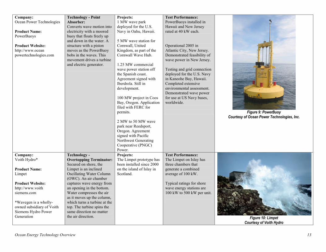
Company: Ocean Power Technologies Product Name: PowerBuoys Product Website: http://www.ocean powertechnologies.com
Technology - Point Absorber: Converts wave motion into electricity with a moored buoy that floats freely up and down in the water. A structure with a piston moves as the PowerBuoy bobs in the waves. This movement drives a turbine and electric generator.
Projects: 1 MW wave park deployed for the U.S. Navy in Oahu, Hawaii. 5 MW wave station for Cornwall, United Kingdom, as part of the Cornwall Wave Hub. 1.25 MW commercial wave power station off the Spanish coast. Agreement signed with Iberdrola. Still in development. 100 MW project in Coos Bay, Oregon. Application filed with FERC for permits. 2 MW to 50 MW wave park near Reedsport, Oregon. Agreement signed with Pacific Northwest Generating Cooperative (PNGC) Power.
Test Performance: PowerBuoys installed in Hawaii and New Jersey rated at 40 kW each. Operational 2005 in Atlantic City, New Jersey. Demonstrated feasibility of wave power in New Jersey. Testing and grid connection deployed for the U.S. Navy in Kaneohe Bay, Hawaii. Completed extensive environmental assessment. Demonstrated wave power for use at US Navy bases, worldwide.
Figure 9: PowerBuoy
Courtesy of Ocean Power Technologies, Inc.
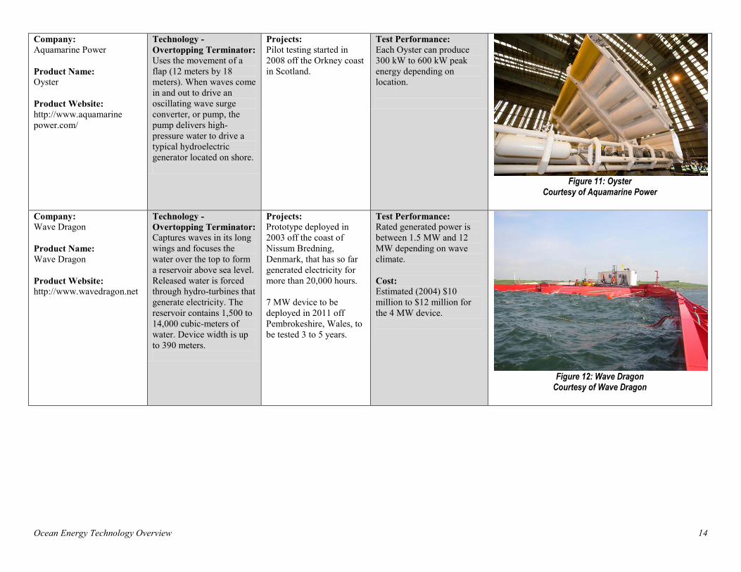
Company: Voith Hydro* Product Name: Limpet Product Website: http://www.voith siemens.com *Wavegen is a wholly-owned subsidiary of Voith Siemens Hydro Power Generation
Technology - Overtopping Terminator: Secured on shore, the Limpet is an inclined Oscillating Water Column (OWC). An air chamber captures wave energy from an opening in the bottom. Water compresses the air as it moves up the column, which turns a turbine at the top. The turbine spins the same direction no matter the air direction.
Projects: The Limpet prototype has been installed since 2000 on the island of Islay in Scotland.
Test Performance: The Limpet on Islay has three chambers that generate a combined average of 100 kW. Typical ratings for shore wave energy stations are 100 kW to 500 kW per unit.
Figure 10: Limpet
Courtesy of Voith Hydro
Ocean Energy Technology Overview 14
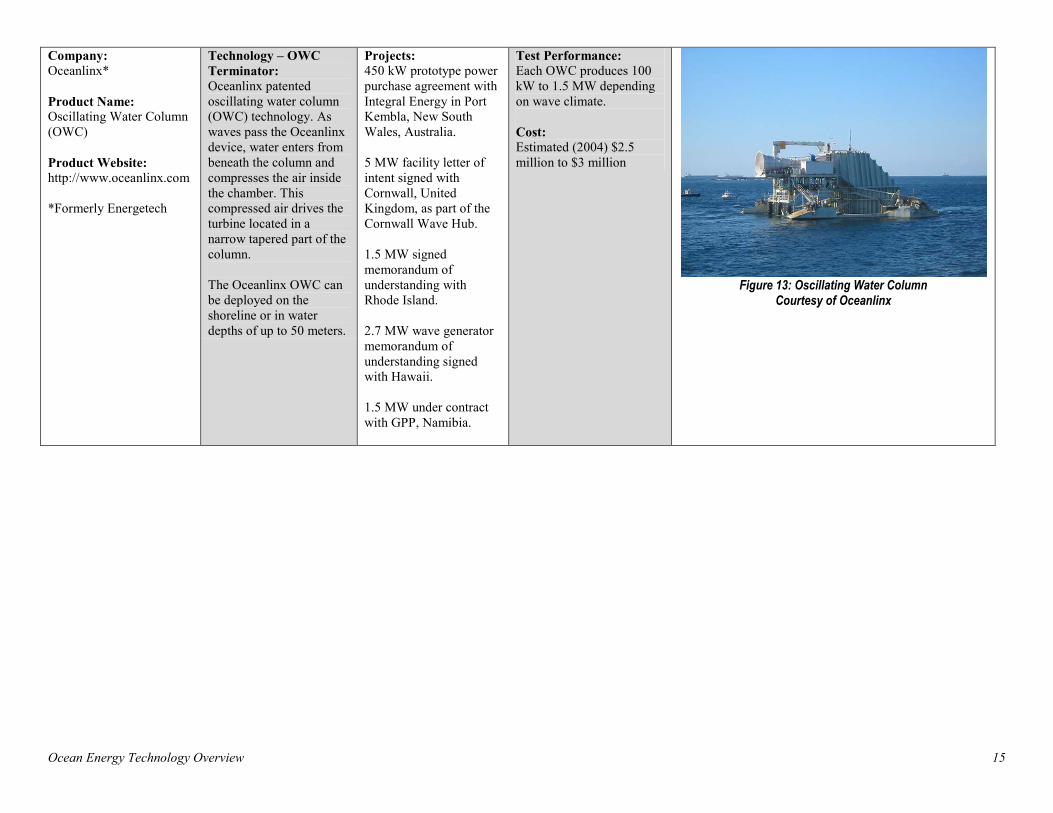
Company: Aquamarine Power Product Name: Oyster Product Website: http://www.aquamarine power.com/
Technology - Overtopping Terminator: Uses the movement of a flap (12 meters by 18 meters). When waves come in and out to drive an oscillating wave surge converter, or pump, the pump delivers high-pressure water to drive a typical hydroelectric generator located on shore.
Projects: Pilot testing started in 2008 off the Orkney coast in Scotland.
Test Performance: Each Oyster can produce 300 kW to 600 kW peak energy depending on location.
Figure 11: Oyster
Courtesy of Aquamarine Power
Company: Wave Dragon Product Name: Wave Dragon Product Website: http://www.wavedragon.net
Technology - Overtopping Terminator: Captures waves in its long wings and focuses the water over the top to form a reservoir above sea level. Released water is forced through hydro-turbines that generate electricity. The reservoir contains 1,500 to 14,000 cubic-meters of water. Device width is up to 390 meters.
Projects: Prototype deployed in 2003 off the coast of Nissum Bredning, Denmark, that has so far generated electricity for more than 20,000 hours. 7 MW device to be deployed in 2011 off Pembrokeshire, Wales, to be tested 3 to 5 years.
Test Performance: Rated generated power is between 1.5 MW and 12 MW depending on wave climate. Cost: Estimated (2004) $10 million to $12 million for the 4 MW device.
Figure 12: Wave Dragon
Courtesy of Wave Dragon
Ocean Energy Technology Overview 15
Company: Oceanlinx* Product Name: Oscillating Water Column (OWC) Product Website: http://www.oceanlinx.com *Formerly Energetech
Technology – OWC Terminator: Oceanlinx patented oscillating water column (OWC) technology. As waves pass the Oceanlinx device, water enters from beneath the column and compresses the air inside the chamber. This compressed air drives the turbine located in a narrow tapered part of the column. The Oceanlinx OWC can be deployed on the shoreline or in water depths of up to 50 meters.
Projects: 450 kW prototype power purchase agreement with Integral Energy in Port Kembla, New South Wales, Australia. 5 MW facility letter of intent signed with Cornwall, United Kingdom, as part of the Cornwall Wave Hub. 1.5 MW signed memorandum of understanding with Rhode Island. 2.7 MW wave generator memorandum of understanding signed with Hawaii. 1.5 MW under contract with GPP, Namibia.
Test Performance: Each OWC produces 100 kW to 1.5 MW depending on wave climate. Cost: Estimated (2004) $2.5 million to $3 million
Figure 13: Oscillating Water Column
Courtesy of Oceanlinx
Ocean Energy Technology Overview 16
3 Tidal and Marine Current Energy
3.1 Overview Tidal current is created from the gravitational pull of the moon and sun. Tidal current moves in two directions and reverses four times per day. Tidal current energy conversion devices are the most common of the two ocean current technologies. Tidal turbines are similar to wind turbines but can be made smaller due to the high energy density of water.
Marine current refers to water that moves continuously and is driven by the motion of the ocean from solar heating and wind near the equator. Marine current moves in one direction with relatively constant flow.
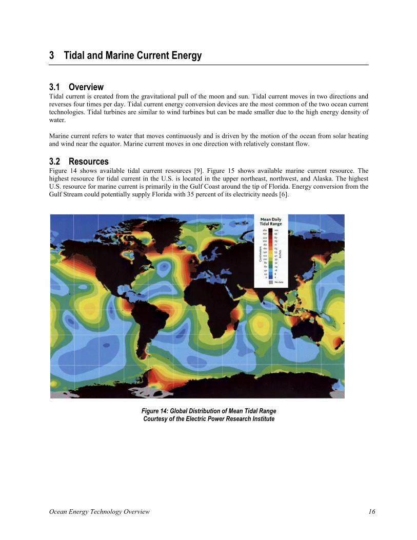
3.2 Resources Figure 14 shows available tidal current resources [9]. Figure 15 shows available marine current resource. The highest resource for tidal current in the U.S. is located in the upper northeast, northwest, and Alaska. The highest U.S. resource for marine current is primarily in the Gulf Coast around the tip of Florida. Energy conversion from the Gulf Stream could potentially supply Florida with 35 percent of its electricity needs [6].
Figure 14: Global Distribution of Mean Tidal Range Courtesy of the Electric Power Research Institute
Ocean Energy Technology Overview 17
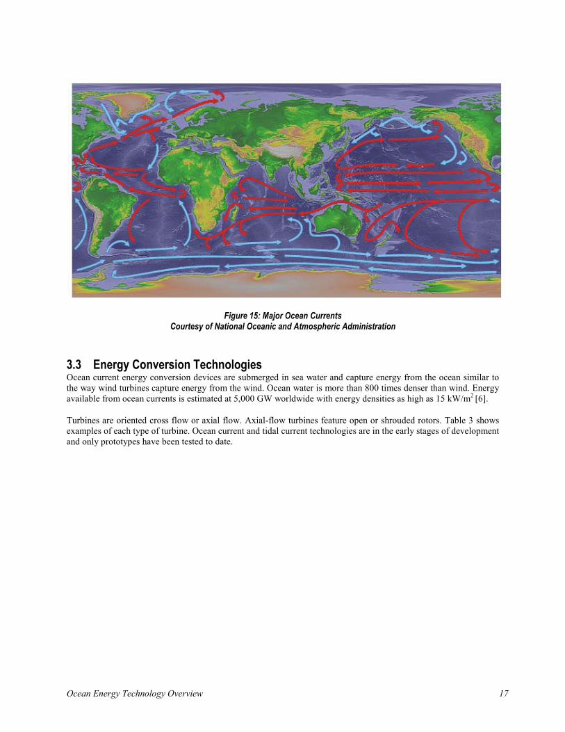
Figure 15: Major Ocean Currents Courtesy of National Oceanic and Atmospheric Administration
3.3 Energy Conversion Technologies Ocean current energy conversion devices are submerged in sea water and capture energy from the ocean similar to the way wind turbines capture energy from the wind. Ocean water is more than 800 times denser than wind. Energy available from ocean currents is estimated at 5,000 GW worldwide with energy densities as high as 15 kW/m2 [6].
Turbines are oriented cross flow or axial flow. Axial-flow turbines feature open or shrouded rotors. Table 3 shows examples of each type of turbine. Ocean current and tidal current technologies are in the early stages of development and only prototypes have been tested to date.
Ocean Energy Technology Overview 18
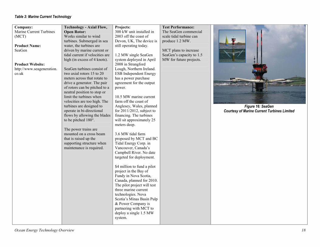
Table 3: Marine Current Technology Company: Marine Current Turbines (MCT) Product Name: SeaGen Product Website: http://www.seageneration. co.uk
Technology - Axial Flow, Open Rotor: Works similar to wind turbines. Submerged in sea water, the turbines are driven by marine current or tidal current if velocities are high (in excess of 4 knots). SeaGen turbines consist of two axial rotors 15 to 20 meters across that rotate to drive a generator. The pair of rotors can be pitched to a neutral position to stop or limit the turbines when velocities are too high. The turbines are designed to operate in bi-directional flows by allowing the blades to be pitched 180°. The power trains are mounted on a cross beam that is raised up the supporting structure when maintenance is required.
Projects: 300 kW unit installed in 2003 off the coast of Devon, UK, The device is still operating today. 1.2 MW single SeaGen system deployed in April 2008 in Strangford Lough, Northern Ireland. ESB Independent Energy has a power purchase agreement for the output power. 10.5 MW marine current farm off the coast of Anglesey, Wales, planned for 2011/2012, subject to financing. The turbines will sit approximately 25 meters deep. 3.6 MW tidal farm proposed by MCT and BC Tidal Energy Corp. in Vancouver, Canada’s Campbell River. No date targeted for deployment. $4 million to fund a pilot project in the Bay of Fundy in Nova Scotia, Canada, planned for 2010. The pilot project will test three marine current technologies. Nova Scotia’s Minas Basin Pulp & Power Company is partnering with MCT to deploy a single 1.5 MW system.
Test Performance: The SeaGen commercial scale tidal turbine can produce 1.2 MW. MCT plans to increase SeaGen’s capacity to 1.5 MW for future projects.
Figure 16: SeaGen
Courtesy of Marine Current Turbines Limited
Ocean Energy Technology Overview 19
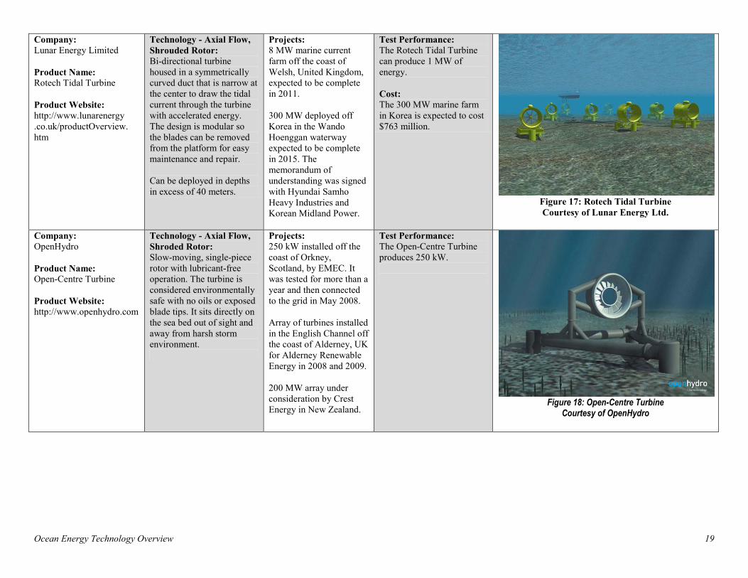
Company: Lunar Energy Limited Product Name: Rotech Tidal Turbine Product Website: http://www.lunarenergy .co.uk/productOverview. htm
Technology - Axial Flow, Shrouded Rotor: Bi-directional turbine housed in a symmetrically curved duct that is narrow at the center to draw the tidal current through the turbine with accelerated energy. The design is modular so the blades can be removed from the platform for easy maintenance and repair. Can be deployed in depths in excess of 40 meters.
Projects: 8 MW marine current farm off the coast of Welsh, United Kingdom, expected to be complete in 2011. 300 MW deployed off Korea in the Wando Hoenggan waterway expected to be complete in 2015. The memorandum of understanding was signed with Hyundai Samho Heavy Industries and Korean Midland Power.
Test Performance: The Rotech Tidal Turbine can produce 1 MW of energy. Cost: The 300 MW marine farm in Korea is expected to cost $763 million.
Figure 17: Rotech Tidal Turbine Courtesy of Lunar Energy Ltd.
Company: OpenHydro Product Name: Open-Centre Turbine Product Website: http://www.openhydro.com
Technology - Axial Flow, Shroded Rotor: Slow-moving, single-piece rotor with lubricant-free operation. The turbine is considered environmentally safe with no oils or exposed blade tips. It sits directly on the sea bed out of sight and away from harsh storm environment.
Projects: 250 kW installed off the coast of Orkney, Scotland, by EMEC. It was tested for more than a year and then connected to the grid in May 2008. Array of turbines installed in the English Channel off the coast of Alderney, UK for Alderney Renewable Energy in 2008 and 2009. 200 MW array under consideration by Crest Energy in New Zealand.
Test Performance: The Open-Centre Turbine produces 250 kW.
Figure 18: Open-Centre Turbine
Courtesy of OpenHydro
Ocean Energy Technology Overview 20
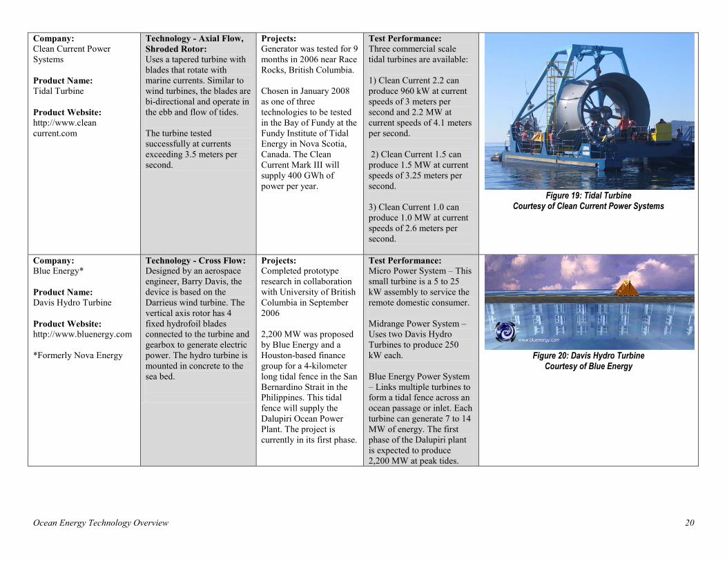
Company: Clean Current Power Systems Product Name: Tidal Turbine Product Website: http://www.clean current.com
Technology - Axial Flow, Shroded Rotor: Uses a tapered turbine with blades that rotate with marine currents. Similar to wind turbines, the blades are bi-directional and operate in the ebb and flow of tides. The turbine tested successfully at currents exceeding 3.5 meters per second.
Projects: Generator was tested for 9 months in 2006 near Race Rocks, British Columbia. Chosen in January 2008 as one of three technologies to be tested in the Bay of Fundy at the Fundy Institute of Tidal Energy in Nova Scotia, Canada. The Clean Current Mark III will supply 400 GWh of power per year.
Test Performance: Three commercial scale tidal turbines are available: 1) Clean Current 2.2 can produce 960 kW at current speeds of 3 meters per second and 2.2 MW at current speeds of 4.1 meters per second. 2) Clean Current 1.5 can produce 1.5 MW at current speeds of 3.25 meters per second. 3) Clean Current 1.0 can produce 1.0 MW at current speeds of 2.6 meters per second.
Figure 19: Tidal Turbine
Courtesy of Clean Current Power Systems
Company: Blue Energy* Product Name: Davis Hydro Turbine Product Website: http://www.bluenergy.com *Formerly Nova Energy
Technology - Cross Flow: Designed by an aerospace engineer, Barry Davis, the device is based on the Darrieus wind turbine. The vertical axis rotor has 4 fixed hydrofoil blades connected to the turbine and gearbox to generate electric power. The hydro turbine is mounted in concrete to the sea bed.
Projects: Completed prototype research in collaboration with University of British Columbia in September 2006 2,200 MW was proposed by Blue Energy and a Houston-based finance group for a 4-kilometer long tidal fence in the San Bernardino Strait in the Philippines. This tidal fence will supply the Dalupiri Ocean Power Plant. The project is currently in its first phase.
Test Performance: Micro Power System – This small turbine is a 5 to 25 kW assembly to service the remote domestic consumer. Midrange Power System – Uses two Davis Hydro Turbines to produce 250 kW each. Blue Energy Power System – Links multiple turbines to form a tidal fence across an ocean passage or inlet. Each turbine can generate 7 to 14 MW of energy. The first phase of the Dalupiri plant is expected to produce 2,200 MW at peak tides.
Figure 20: Davis Hydro Turbine
Courtesy of Blue Energy

Ocean Energy Technology Overview 21
Company: Verdant Power Product Name: Free Flow Turbine Product Website: http://www.verdant power.com/
Technology - Axial Flow, Open Rotor: Verdant Power systems are modular, three-blade horizontal-axis turbines that move slowly with the natural currents (~32 rpm) and offer a low-impact kinetic hydropower solution. The turbines are like wind turbines and can pivot with the changing direction of the tide. The free flow systems are completely submerged in water and operate without being seen.
Projects: 6-turbine marine current farm in New York City’s East River will expand to more than 300 turbines. The project produces 1 MWh of electricity per day. 2002-2006: Phase 1 Prototype Testing 2006-2008: Phase 2 Demonstration 2009-2012: Phase 3 Commercial MW scale
Test Performance: The Free Flow Turbine can be scaled in unit size and number. One Free Flow turbine produces 7 kW of energy with an average marine current velocity of 2.0 meters per second. 1 MW is projected from a future 11 meter blade turbine.
Figure 21: Free Flow Turbine Courtesy of Verdant Power
Ocean Energy Technology Overview 22
4 Ocean Tidal Energy
4.1 Overview High and low tides occur every 12 hours. With ocean tidal energy, potential energy from these tides is captured similarly to a dam in an estuary. The first commercial-scale ocean energy project was in St. Malo, France, in 1966, which still produces 240 MWh/year. 4.2 Resources To capture viable power from tidal energy, in most cases, the difference in high tide and low tide height must be at least five meters (16 feet). Only 20 to 40 locations on earth have this potential, most of which are located in the Bay of Fundy by Nova Scotia.
4.3 Energy Conversion Technologies Building barrages or dams is unpopular in the U.S. because of the environmental considerations. Barrages block navigation, impede fish migration, and change the tidal regime downstream. With the use of low-head hydroelectric generating equipment, new trials are in process to build lagoons in shallow, offshore rock mound impoundments of tidal flats. The impoundments have less environmental impact than a barrage since migratory fish can simply swim around the structure and boats can navigate past. Table 4 provides an example of this technology.

Ocean Energy Technology Overview 23
Table 4: Tidal Current Technology
Company: Tidal Electric Product Name: Tidal Lagoons Product Website: http://www.tidalelectric.com/index.htm
Technology: Uses new technology that eliminates the conventional barrage by building offshore rock mound impoundments. The technology takes advantage of typical low-head hydroelectric generating equipment. Shallow tidal flats (a few yards from low tide level) can provide sufficient energy to make the project cost effective. Turbines are submerged in the impound structure and connected to the grid by underground cables.
Projects: 60 MW project proposed for Swansea Bay, United Kingdom. The overall resource is estimated to be 60,000 MW for tidal energy. 300 MW project signed to install a Tidal Lagoon in coastal waters off China.
Test Performance: The offshore tidal generator uses a proven mixed-flow reversible bulb turbine. The power available is site specific and dependant of the tide. The power is a function of the sluice flow rate and the head on the sluice captured from the impoundment. The available head is highest at extreme low tide and extreme high tide.
Figure 22: Tidal Lagoon
Courtesy of Tidal Electric
Ocean Energy Technology Overview 24
5 Ocean Thermal Energy Conversion
5.1 Overview In 1881, a French physicist named Jacques Arsene d’Arsonval discovered the concept of ocean thermal energy conversion (OTEC). His student, Georges Claude, built the first open cycle OTEC plant in Cuba in 1930. With this technology, temperature gradient from the ocean surface to deeper waters converts heat energy to electricity. It functions best when there is a temperature difference of at least 20°C (36°F). In 1979, the first 18 kW closed cycle OTEC demonstration plant was built in Keahole Point, Hawaii. This project was known as "Mini-OTEC.” In 1990, a 103 kW open cycle OTEC demonstration plant was built in Keahole Point, Hawaii. A planned commercial project to produce 1 MW was also expected in 2009 [10]. In 2006, DOE assigned FEMP and the National Renewable Energy Laboratory (NREL) to team with the U.S. Navy and U.S. Army to develop an OTEC facility in the Republic of Marshall Islands (RMI) on or near Kwajalein Island, RMI [11]. According to the memorandum, the facility will produce 7MW/yr and displace 47,000MWh/yr, saving Kwajalein 38 percent of its baseline diesel use.
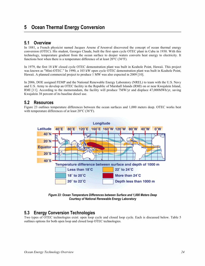
5.2 Resources Figure 23 outlines temperature differences between the ocean surfaces and 1,000 meters deep. OTEC works best with temperature differences of at least 20°C (36°F).
Figure 23: Ocean Temperature Differences between Surface and 1,000 Meters Deep Courtesy of National Renewable Energy Laboratory
5.3 Energy Conversion Technologies Two types of OTEC technologies exist: open loop cycle and closed loop cycle. Each is discussed below. Table 5 outlines options for both open loop and closed loop OTEC technologies.
Ocean Energy Technology Overview 25
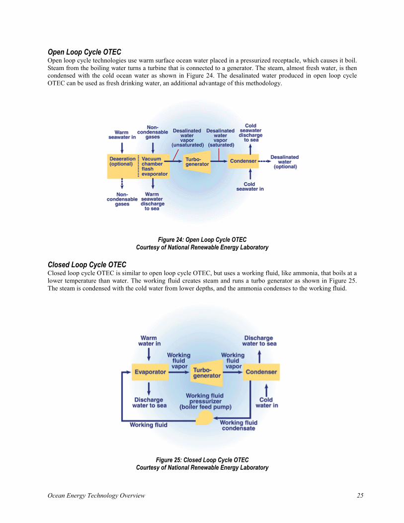
Open Loop Cycle OTEC Open loop cycle technologies use warm surface ocean water placed in a pressurized receptacle, which causes it boil. Steam from the boiling water turns a turbine that is connected to a generator. The steam, almost fresh water, is then condensed with the cold ocean water as shown in Figure 24. The desalinated water produced in open loop cycle OTEC can be used as fresh drinking water, an additional advantage of this methodology.
Figure 24: Open Loop Cycle OTEC Courtesy of National Renewable Energy Laboratory
Closed Loop Cycle OTEC Closed loop cycle OTEC is similar to open loop cycle OTEC, but uses a working fluid, like ammonia, that boils at a lower temperature than water. The working fluid creates steam and runs a turbo generator as shown in Figure 25. The steam is condensed with the cold water from lower depths, and the ammonia condenses to the working fluid.
Figure 25: Closed Loop Cycle OTEC
Courtesy of National Renewable Energy Laboratory
Ocean Energy Technology Overview 26
Table 5: OTEC Technology
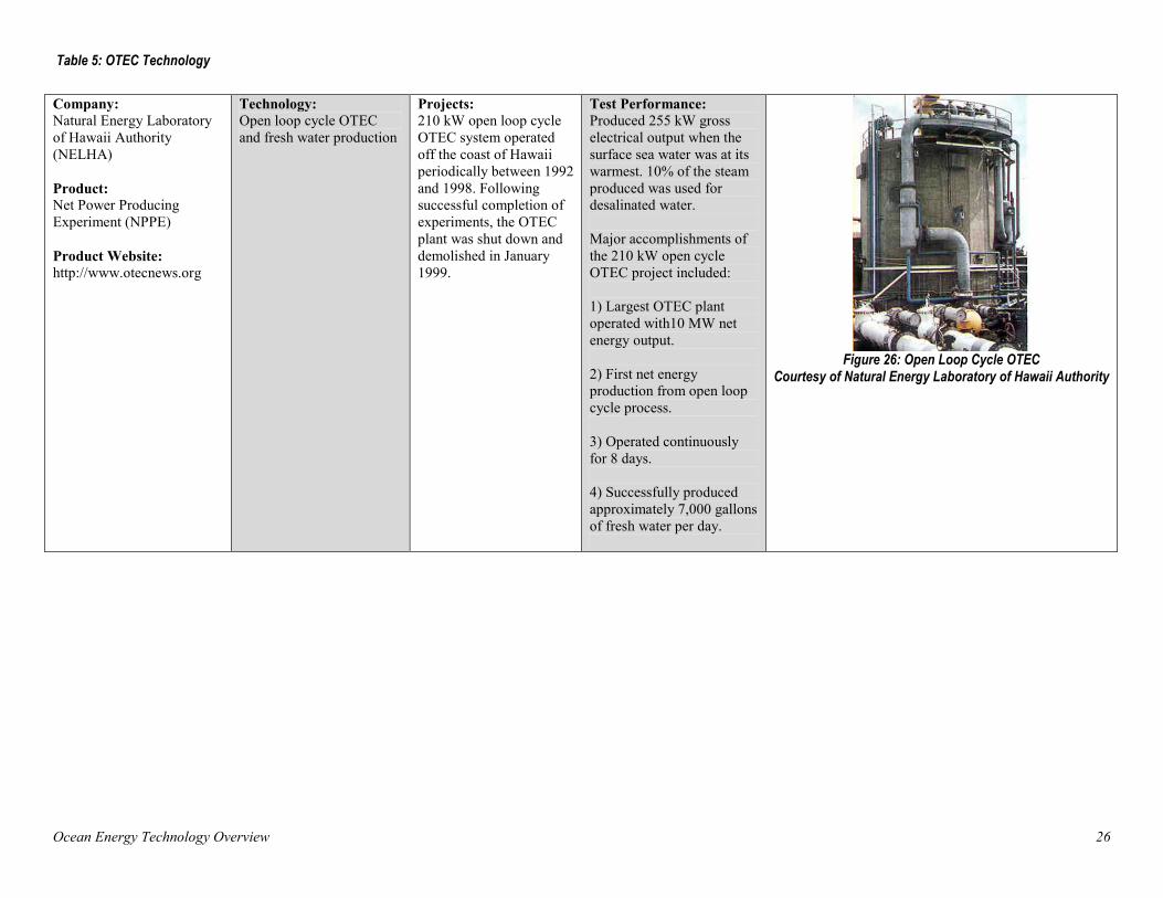
Company: Natural Energy Laboratory of Hawaii Authority (NELHA) Product: Net Power Producing Experiment (NPPE) Product Website: http://www.otecnews.org
Technology: Open loop cycle OTEC and fresh water production
Projects: 210 kW open loop cycle OTEC system operated off the coast of Hawaii periodically between 1992 and 1998. Following successful completion of experiments, the OTEC plant was shut down and demolished in January 1999.
Test Performance: Produced 255 kW gross electrical output when the surface sea water was at its warmest. 10% of the steam produced was used for desalinated water. Major accomplishments of the 210 kW open cycle OTEC project included: 1) Largest OTEC plant operated with10 MW net energy output. 2) First net energy production from open loop cycle process. 3) Operated continuously for 8 days. 4) Successfully produced approximately 7,000 gallons of fresh water per day.
Figure 26: Open Loop Cycle OTEC
Courtesy of Natural Energy Laboratory of Hawaii Authority
Ocean Energy Technology Overview 27
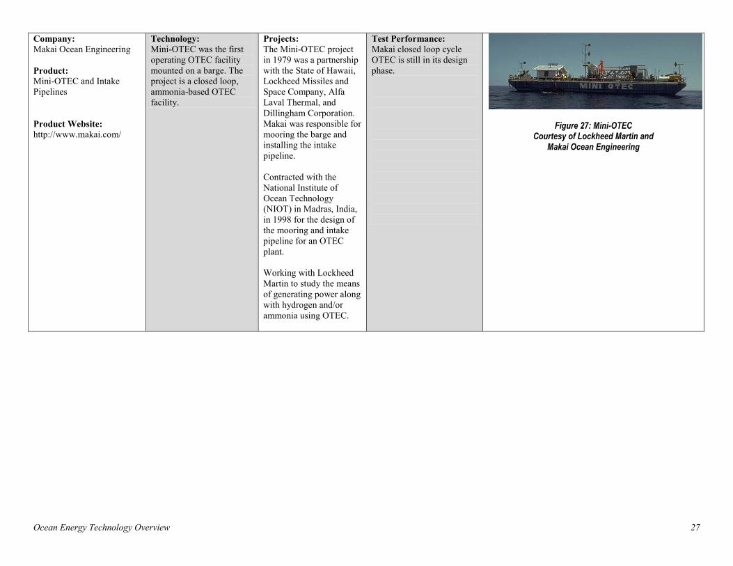
Company: Makai Ocean Engineering Product: Mini-OTEC and Intake Pipelines Product Website: http://www.makai.com/
Technology: Mini-OTEC was the first operating OTEC facility mounted on a barge. The project is a closed loop, ammonia-based OTEC facility.
Projects: The Mini-OTEC project in 1979 was a partnership with the State of Hawaii, Lockheed Missiles and Space Company, Alfa Laval Thermal, and Dillingham Corporation. Makai was responsible for mooring the barge and installing the intake pipeline. Contracted with the National Institute of Ocean Technology (NIOT) in Madras, India, in 1998 for the design of the mooring and intake pipeline for an OTEC plant. Working with Lockheed Martin to study the means of generating power along with hydrogen and/or ammonia using OTEC.
Test Performance: Makai closed loop cycle OTEC is still in its design phase.
Figure 27: Mini-OTEC Courtesy of Lockheed Martin and
Makai Ocean Engineering
Ocean Energy Technology Overview 28
6 Conclusion
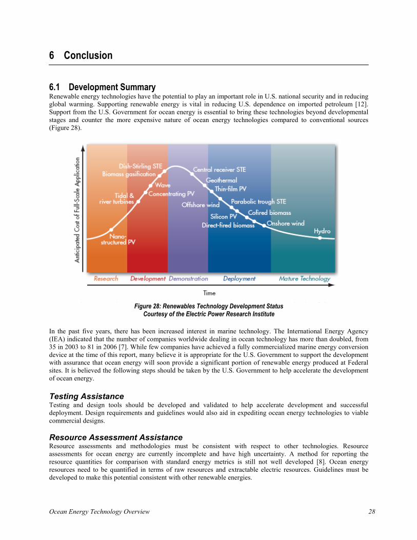
6.1 Development Summary Renewable energy technologies have the potential to play an important role in U.S. national security and in reducing global warming. Supporting renewable energy is vital in reducing U.S. dependence on imported petroleum [12]. Support from the U.S. Government for ocean energy is essential to bring these technologies beyond developmental stages and counter the more expensive nature of ocean energy technologies compared to conventional sources (Figure 28).
Figure 28: Renewables Technology Development Status
Courtesy of the Electric Power Research Institute In the past five years, there has been increased interest in marine technology. The International Energy Agency (IEA) indicated that the number of companies worldwide dealing in ocean technology has more than doubled, from 35 in 2003 to 81 in 2006 [7]. While few companies have achieved a fully commercialized marine energy conversion device at the time of this report, many believe it is appropriate for the U.S. Government to support the development with assurance that ocean energy will soon provide a significant portion of renewable energy produced at Federal sites. It is believed the following steps should be taken by the U.S. Government to help accelerate the development of ocean energy. Testing Assistance Testing and design tools should be developed and validated to help accelerate development and successful deployment. Design requirements and guidelines would also aid in expediting ocean energy technologies to viable commercial designs.
Resource Assessment Assistance Resource assessments and methodologies must be consistent with respect to other technologies. Resource assessments for ocean energy are currently incomplete and have high uncertainty. A method for reporting the resource quantities for comparison with standard energy metrics is still not well developed [8]. Ocean energy resources need to be quantified in terms of raw resources and extractable electric resources. Guidelines must be developed to make this potential consistent with other renewable energies.

Ocean Energy Technology Overview 29
Sharing Technology Many issues faced by ocean energy today are similar to issues faced by wind, solar, and other renewable energies only a few years ago. Sharing expertise in modeling, testing, GIS resources, and grid integration will help ocean energy development be completed in a safe and timely manner. The DOE EERE Wind & Hydropower Technologies Program created a database that documents ocean technologies, companies, and the status of research projects around the world [13]. The database is located at:
• http://www1.eere.energy.gov/windandhydro/hydrokinetic/
Ocean Energy Technology Overview 30
References
1. Gary, T.J., Gashus, O.K. Tidal Power. New York: Plenum Press, 1972.
2. Micklethwait, J. "Technology Quarterly; The Coming Wave." The Economist; June 7, 2008.
3. Goswami, D. Yogi, Kreith, Frank. Energy Conversion. Boca Raton: CRC Press, 2007.
4. Bedard, R., Previsic, M., Hagerman, G. "North American Ocean Energy Status March 2007." Electric Power Research Institute (EPRI) Tidal Power (TP); Volume 8, 2007.
5. OCS Alternative Energy and Alternate Use Programmatic EIS Information Center, Ocean Current Energy. http://ocsenergy.anl.gov/guide/current/index.cfm. Accessed March 13, 2009.
6. U.S. Department of the Interior Minerals Management Services. "Ocean Current Energy Potential on the U.S. Outer Continental Shelf." May 2006.
7. Murray, R. "Review and Analysis of Ocean Energy Systems Development and Supporting Policies." International Energy Agency (IEA); June 28, 2006.
8. Musial, W. "Status of Wave and Tidal Power Technologies for the United States." National Renewable Energy Laboratory Technical Report (NREL/TP-500-43240); June 2008.
9. McGowin C. "Ocean Tidal and Wave Energy: Renewable Energy Technical Assessment Guide." Electric Power Research Institute (EPRI); December 2005.
10. Global Energy Concepts. "A Catalog of Potential Sites for Renewable Energy in Hawaii." December 2006.
11. Busquets, Kelly, Cable, B., Walker, A. "FEMP Assistance to US Army Ocean Thermal Energy Conversion (OTEC) Project." 2006.
12. Douglas, J. "Renewables: A Promising Coalition of Many." Electric Power Research Institute (EPRI) Journal; Summer 2007.
13. U.S. Department of Energy, Wind & Hydropower Technologies Program. http://www1.eere.energy.gov/windandhydro/hydrokinetic/. Accessed April 2009.

For More Information:EERE Information Center 1-877-EERE-INF or 1-877-337-3463 www.eere.energy.gov/femp/
Prepared by the National Renewable Energy Laboratory (NREL) NREL is a national laboratory of the U.S. Department of Energy Office of Energy Efficiency and Renewable Energy Operated by the Alliance for Sustainable Energy, LLC
DOE/GO-102009-2823 • July 2009
ENERGYU.S. DEPARTMENT OF
Energy Efficiency & Renewable Energy
Related Documents