Volume XIV, Revision L 5-29-01 NSTS 07700, Volume XIV Space Shuttle System Payload Accommodations Revision L Downloaded from http://www.everyspec.com

Welcome message from author
This document is posted to help you gain knowledge. Please leave a comment to let me know what you think about it! Share it to your friends and learn new things together.
Transcript
Volume XIV, Revision L 5-29-01
NSTS 07700, Volume XIV
Space Shuttle System Payload Accommodations
Revision L
Downloaded from http://www.everyspec.com
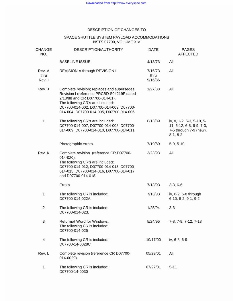
DESCRIPTION OF CHANGES TO
SPACE SHUTTLE SYSTEM PAYLOAD ACCOMMODATIONSNSTS 07700, VOLUME XIV
CHANGENO.
DESCRIPTION/AUTHORITY DATE PAGESAFFECTED
BASELINE ISSUE 4/13/73 All
Rev. Athru
Rev. I
REVISION A through REVISION I 7/16/73thru
9/16/86
All
Rev. J Complete revision; replaces and supersedesRevision I (reference PRCBD S04219F dated2/18/88 and CR D07700-014-01).The following CR’s are included:D07700-014-002, D07700-014-003, D07700-014-004, D07700-014-005, D07700-014-006.
1/27/88 All
1 The following CR’s are included:D07700-014-007, D07700-014-008, D07700-014-009, D07700-014-010, D07700-014-011.
6/13/89 iv, v, 1-2, 5-3, 5-10, 5-11, 5-12, 6-8, 6-9, 7-3,7-5 through 7-9 (new),8-1, 8-2
Photographic errata 7/19/89 5-9, 5-10
Rev. K Complete revision (reference CR D07700-014-020).The following CR’s are included:D07700-014-012, D07700-014-013, D07700-014-015, D07700-014-016, D07700-014-017,and D07700-014-018
3/23/93 All
Errata 7/13/93 3-3, 6-6
1 The following CR is included:D07700-014-022A.
7/13/93 iv, 6-2, 6-8 through6-10, 8-2, 9-1, 9-2
2 The following CR is included:D07700-014-023.
1/25/94 3-3
3 Reformat Word for Windows.The following CR is included:D07700-014-025
5/24/95 7-8, 7-9, 7-12, 7-13
4 The following CR is included:D07700-14-0028C
10/17/00 iv, 6-8, 6-9
Rev. L Complete revision (reference CR D07700-014-0029)
05/29/01 All
1 The following CR is included:D07700-14-0030
07/27/01 5-11
Downloaded from http://www.everyspec.com
i Volume XIV, Revision L 5-29-01
Preface
This document, its attachment, and its various appendixes describe currently approved and authorized
interfaces between the Space Shuttle system and Space Shuttle payloads.
The applicability of each of these specialized documents will depend upon the characteristics of the
payload to be flown and will be specified in the individual payload integration plan (IP). The design
requirements outlined in this document, its attachment, and its appendixes are mandatory and may not be
violated unless specifically agreed upon in the individual IP or individual interface control document (ICD).
Configuration control of this document will be accomplished through application of procedures contained
in NSTS 07700, Vol. IV, Configuration Management Requirements, current issue.
Questions and recommendations concerning this document should be addressed to:
Manager, Space Shuttle Customer and Flight Integration OfficeNational Aeronautics and Space Administration
Lyndon B. Johnson Space CenterHouston, Texas 77058
Signed Michele Brekke Michele BrekkeManagerSpace Shuttle Customer and Flight Integration Office
Downloaded from http://www.everyspec.com

ii Volume XIV, Revision L 5-29-01
SPACE SHUTTLEPROGRAM DEFINITION & REQUIREMENTS - NSTS 07700
PROGRAMSTRUCTURE
ANDRESPONSIBILITIES
BOOKS 1-3
PROGRAMDESCRIPTION
ANDREQUIREMENTS
BASELINE
SPACE SHUTTLEPROGRAM/SPACE
STATION FREEDOMPROGRAM
PROGRAMMANAGEMENT PLAN
COMPUTERSYSTEMS
ANDSOFTWARE
REQUIREMENTSBOOKS 1-3
SYSTEM INTEGRITYASSURANCE
PROGRAM PLAN
FLIGHT SUPPORTEQUIPMENT (FSE)
MANAGEMENT
INFORMATIONMANAGEMENT
REQUIREMENTS
CONFIGURATIONMANAGEMENT
REQUIREMENTS
FLIGHTDEFINITION
ANDREQUIREMENTS
DIRECTIVE
INTEGRATEDLOGISTICS
REQUIREMENTS
SPACE SHUTTLEFLIGHT AND
GROUND SYSTEMSPECIFICATION
GROUND SYSTEMSINTEGRATION AND
OPERATIONS
OPERATIONS
SPACESHUTTLE SYSTEM
PAYLOADACCOMMODATIONS
VOL
XIV
VOL
I
VOL
II
VOL
XVI
VOL
XI
VOL
VI
VOL
V
VOL
XVII
VOL
XII
VOL
X
VOL
IX
NOTE:RESERVED:RETIRED:
THE FOLLOWING VOLUME NUMBERS AREVOLUMES XVIIVOLUMES II-BK4, VI-BK2, VII, XIII
RESOURCEMANAGEMENTPOLICY AND
REQUIREMENTS
VOL
III
VOL
IV
VOL
XV
VOL
VIII
RESOURCEREQUIREMENTS
TECHNICALREQUIREMENTS
MANAGEMENTREQUIREMENTS
Downloaded from http://www.everyspec.com

iii Volume XIV, Revision L 5-29-01
Table of Contents
1 - Introduction 1-1
2 - Space Shuttle Program Organization 2-1
2.1 NASA Headquarters ......................................................................................................... 2-12.2 Lyndon B. Johnson Space Center .................................................................................... 2-12.3 John F. Kennedy Space Center........................................................................................ 2-12.4 George C. Marshall Space Flight Center.......................................................................... 2-12.5 Goddard Space Flight Center ........................................................................................... 2-12.6 Contacts............................................................................................................................ 2-2
3 - Space Shuttle Program Description and General Capabilities 3-1
3.1 Space Shuttle Vehicle....................................................................................................... 3-13.2 Typical Space Shuttle Mission.......................................................................................... 3-23.3 Space Shuttle Cargo Capability........................................................................................ 3-4
3.3.1 Payload Control Weight Definition ............................................................. 3-4
4 - Safety, Reliability, and Quality Assurance 4-1
5 - Payload Accommodations 5-1
5.1 Physical Accommodations................................................................................................ 5-15.2 Avionics Accommodations................................................................................................ 5-15.3 Electrical Power ................................................................................................................ 5-45.4 Command Services .......................................................................................................... 5-65.5 Data Processing and Display Services............................................................................. 5-85.6 Recording ......................................................................................................................... 5-85.7 Timing............................................................................................................................... 5-85.8 Thermal Accommodations................................................................................................ 5-95.9 Ground Support Equipment Umbilical .............................................................................. 5-95.10 Pointing............................................................................................................................. 5-95.11 Payload Deployment......................................................................................................... 5-95.12 Small Payload Accommodations ...................................................................................... 5-9
5.12.1 Physical Accommodations......................................................................... 5-95.12.2 Electrical Power ......................................................................................... 5-95.12.3 Command Services ................................................................................... 5-105.12.4 Data Processing and Display Services ...................................................... 5-105.12.5 Timing ........................................................................................................ 5-105.12.6 Thermal Accommodations......................................................................... 5-10
5.13 Middeck Payload Accommodations.................................................................................. 5-105.13.1 Physical Accommodations......................................................................... 5-115.13.2 Electrical Power ......................................................................................... 5-115.12.3 Command and Monitoring ......................................................................... 5-115.13.4 Cooling....................................................................................................... 5-11
5.14 Get-Away Special Payload Accommodations................................................................... 5-115.15 Remote Manipulator System ............................................................................................ 5-11
Downloaded from http://www.everyspec.com
iv Volume XIV, Revision L 5-29-01
6 - Payload Integration Process 6-1
6.1 Overview........................................................................................................................... 6-26.2 Formal Agreements Development.................................................................................... 6-26.3 Documentation.................................................................................................................. 6-26.4 Payload Classification Criteria .......................................................................................... 6-66.5 Flight Assignment Priority ................................................................................................. 6-7
7 - Cargo Integration and Manifest Development 7-1
8 - Customer Funded Services 8-1
9 - Acronyms and Abbreviations 9-1
10 - Glossary 10-1
Tables
6-I PAYLOAD DOCUMENTATION REQUIRED FOR FLIGHT ASSIGNMENT .................... 6-7
7-I MISSION READINESS REVIEW SUMMARY .................................................................. 7-4
Figures
1-1 Space Shuttle Program customer documentation tree..................................................... 1-2
3-1 Space Shuttle system ....................................................................................................... 3-23-2 Payload bay ...................................................................................................................... 3-33-3 Aft flight deck .................................................................................................................... 3-33-4 Middeck ............................................................................................................................ 3-33-5 Mission phases (typical) ................................................................................................... 3-4
5-1 Orbiter coordinate system................................................................................................. 5-15-2 Payload umbilical service panels...................................................................................... 5-25-3 Attach fittings for payload ................................................................................................. 5-35-4 Three- and five-point loads support.................................................................................. 5-45-5 Standard interface panel configuration............................................................................. 5-55-6 Avionics provisions - standard accommodation ............................................................... 5-65-7 Standard switch panel ...................................................................................................... 5-75-8 Sidewall-mounted payloads.............................................................................................. 5-105-9 Middeck lockers................................................................................................................ 5-11
6-1 Payload integration process ............................................................................................. 6-16-2 Request for Flight Assignment (NASA Form 1628).......................................................... 6-3
7-1 Payload processing from delivery to launch ..................................................................... 7-27-2 Payload Readiness of Integration Statement ................................................................... 7-67-3 Payload Readiness for Flight Statement .......................................................................... 7-77-4 Payload Readiness Statement for Middeck...................................................................... 7-9
Downloaded from http://www.everyspec.com
1-1 Volume XIV, Revision L 5-29-01
Introduction
1This document contains information on the SpaceShuttle system required by payload customersduring the design definition phase. The purpose ofthis document is to provide potential customerswith an official source of information on SpaceShuttle capability to deliver payloads into orbit andreturn them to Earth; on services provided topayload customers; and on the means by whichpayload customers can avail themselves of theseservices. Standard interface provisions betweenthe orbiter and payloads are also defined. Withthis information, payload planning and designstudies can be undertaken incorporating knownshuttle capabilities and interface provisions.Additionally, information is provided on the processemployed by the Space Shuttle Program (SSP) tointegrate individual payloads into the shuttle, andthe process of manifesting multiple payloads andproviding for their integration into a shuttle missionor flight.
This document should be used in conjunction withthe documents outlined in Figure 1-1.
Specific safety requirements which payloadcustomers must satisfy are contained in theprimary safety documents noted in Figure 1-1.
Appendixes 1 through 10 contain systemdescription and design data concerningaccommodations and interface requirements.These appendixes are available on an as-neededbasis. They are:
Appendix 1: Contamination EnvironmentAppendix 2: ThermalAppendix 3: Electrical Power and AvionicsAppendix 4: Structures and MechanicsAppendix 5: Ground OperationsAppendix 6: Mission Planning and Flight
DesignAppendix 7: Extravehicular ActivitiesAppendix 8: Payload Deployment and
Retrieval SystemAppendix 9: Intravehicular ActivitiesAppendix 10: Integration Hardware
Standard integration plans (SIPs), also referred toas blank books, have been developed to serve asguides for preparation of the customer’s integrationplan (IP). Integration plans could be a payloadintegration plan (PIP), mission integration plan(MIP), carrier integration plan (CIP), or anintegration plan (IP). Blank book annexes are alsoavailable, as required, to facilitate definition ofdetailed integration requirements.
In addition, the Space Shuttle Program PayloadBay User's Guide, NSTS 21492, is available. Aweb site, http://shuttlepayloads.jsc.nasa.gov,contains hyperlinks to program documentation inaddition to some general information on thepayload integration process.
Attachment 1, Shuttle Orbiter/Cargo StandardInterfaces, ICD 2-19001 is the principal documentdefining Space Shuttle/payload interfaces. Inaddition, several standard interface definitiondocuments (IDDs) and unique interface controldocuments (ICDs) are provided to facilitate thecustomer’s development of a payload-unique ICD.Normally only dedicated payloads require thecomplete ICD. Therefore, other payloadcustomers should refer to the IDD or unique ICDappropriate to their payload.
When a prospective customer has negotiated aformal agreement (launch services agreement(LSA), joint endeavor agreement (JEA), ormemorandum of understanding (MOU), etc.) withthe National Aeronautics and Space Administration(NASA) Headquarters, a payload integrationmanager (PIM) will be assigned at Lyndon B.Johnson Space Center (JSC), and a launch sitesupport manager (LSSM) at John F. KennedySpace Center (KSC). The PIM will coordinate withthe JSC customer payload support group toprovide the payload customer with requireddocumentation.
Downloaded from http://www.everyspec.com

1-2 Volume XIV, Revision L 5-29-01
APPENDIX 1 -CONTAMINATIONENVIRONMENT
APPENDIX 2 -THERMAL
APPENDIX 3 -ELECTRICAL POWERAND AVIONICS
APPENDIX 4 -STRUCTURES ANDMECHANICS
APPENDIX 5 -GROUND OPERATIONS
APPENDIX 6 -MISSION PLANNINGAND FLIGHT DESIGN
APPENDIX 7 -EXTRAVEHICULARACTIVITIES
APPENDIX 8 -PAYLOADDEPLOYMENT ANDRETRIEVAL SYSTEM
APPENDIX 9 -INTRAVEHICULARACTIVITIES
APPENDIX 10 -INTEGRATIONHARDWARE
NSTS 21000-SIP-ATTATTACHED PAYLOADS
NSTS 21000-SIP-DRPDEPLOYABLE/RETRIEVABLEPAYLOADS
NSTS 21000-SIP-GASGET AWAY SPECIALPAYLOADS
NSTS 21000-SIP-MDKMIDDECK PAYLOADS
NSTS 21000-SIP-ISSINTERNATIONAL SPACESTATION
NSTS 21000-IDD-SMLSMALL PAYLOADS
NSTS 21000-IDD-ISSINTERNATIONAL SPACESTATION
NSTS 21000-IDD-MDKMIDDECK PAYLOADS
*ANNEXES AND DATA SUBMITTALS(NOTE: APPROPRIATE ANNEXES ARE OUTLINED IN THEINDIVIDUAL SIP’s)ANNEX 1 PAYLOAD DATA PACKAGEANNEX 2 FLIGHT PLANNINGANNEX 3 (SUPERSEDED BY SIP TABLE 8.1, DATA SUBMITTALSANNEX 4 COMMAND AND DATAANNEX 5 POCCANNEX 6 (SUPERSEDED BY INTERFACE CONTROL ANNEX)ANNEX 7 TRAININGANNEX 8 LAUNCH SITE SUPPORT PLANANNEX 9 (SUPERSEDED BY THE OPERATIONS AND MAINTENANCE REQUIREMENTS SPECIFICATIONS DOCUMENT (OMRSD)ANNEX 11 EXTRAVEHICULAR ACTIVITIES (EVA)
*ANNEXES
ORBITER/PAYLOADINTERFACES
SAFETYx 45 SPW HB S-100/KHB 1700.7x NSTS 1700.7B x NSTS 16879x NSTS/ISS 13830C x NSTS/ISS 18798x NSTS 14046 x NSTS 22648
VOL. XIV APPENDIXES -SYSTEM DESCRIPTIONAND DESIGN DATA
SHUTTLE/PAYLOADSTANDARD INTEGRATIONPLANS (SIP’s)
NSTS 07700 VOLUME XIVSPACE SHUTTLE SYSTEM PAYLOAD ACCOMMODATIONS
NSTS 21492 - PAYLOADBAY PAYLOAD USER'SGUIDE
ICD 2-19001:VOL. XIV,ATTACHMENT 1 -SHUTTLE ORBITER/CARGO STANDARDINTERFACES
Figure 1-1.- Space Shuttle Program customer documentation tree.
Downloaded from http://www.everyspec.com

2-1 Volume XIV, Revision L 5-29-01
Space Shuttle Program Organization
2Several NASA centers are involved in activities ofinterest to SSP customers, ranging fromdevelopment of scientific experiments to payloadoperation during a flight. The followingorganizations are directly involved with integrationof a payload into the Space Shuttle.
2.1 NASA Headquarters
Overall management of the SSP is theresponsibility of the Office of Space Flight at NASAHeadquarters in Washington, D. C.
The Space Shuttle Operations Utilization Divisionwithin the Office of Space Flight is responsible foroverall shuttle flight scheduling, including thereceipt of Request for Flight Assignment (NASAForm 1628) and earnest money payments. ThisDivision is also responsible for LSA, JEA, MOU,etc. negotiation and implementation, which coversall business, policy, legal, and financial aspects ofa customer’s launch.
2.2 Lyndon B. Johnson SpaceCenter
The SSP at JSC in Houston, Texas, manages thedevelopment and operation of the Space Shuttle.
The JSC Customer and Flight Integration Office isresponsible for managing integration of thecustomer’s payload into the Space Shuttle. A PIMis assigned to each customer to serve as thesingle point of contact between the SSP and thecustomer.
Working groups for engineering and operationsplanning are established as needed between thecustomer and the SSP. These working groupsdefine interface and operational requirements,identify and define engineering tasks andanalyses, and exchange required data.
2.3 John F. Kennedy SpaceCenter
KSC is the launch site and the primary landing sitefor the Space Shuttle. Located at Merritt Island,Florida, KSC is responsible for implementingactivities associated with preparing the SpaceShuttle and its payloads for launch, landing, andpostflight services.
KSC is responsible for payload processing andsupport at the launch site. Each customer isassigned an LSSM to serve as a single point ofcontact between the customer and KSC for alllaunch site support and payload processingactivities.
2.4 George C. Marshall SpaceFlight Center
George C. Marshall Space Flight Center (MSFC) inHunstville, Alabama, is responsible for managingdevelopment of solid rocket boosters (SRBs), andSpace Shuttle Main Engines (SSMEs).
2.5 Goddard Space FlightCenter
Goddard Space Flight Center (GSFC) inGreenbelt, Maryland, is responsible for managingthe worldwide NASA communications network,including the Tracking Data and Relay SatelliteSystem (TDRSS). In addition, GSFC oversees theGet-Away Special (GAS) program and severalother small payload carrier programs.
Downloaded from http://www.everyspec.com

2-2 Volume XIV, Revision L 5-29-01
2.6 Contacts
The following NASA addresses and telephonenumbers are provided for payload customers:
Space Shuttle Operations Utilization (CodeMO)National Aeronautics and SpaceAdministrationWashington, D. C. 20546(202) 358-2347
Customer and Flight Integration Office (CodeMT)National Aeronautics and SpaceAdministrationLyndon B. Johnson Space CenterHouston, Texas 77058(713) 483-1145
ISS/Payloads Processing Directorate(Code UB)National Aeronautics and SpaceAdministrationJohn F. Kennedy Space CenterKennedy Space Center, Florida 32899(407) 867-7411
For payload processing, payload launch andlanding planning, or ground operations planning:ISS/Payloads Processing (UB)
National Aeronautics and SpaceAdministrationJohn F. Kennedy Space CenterKennedy Space Center, Florida 32899(407) 867-4545
For GAS payloads:
Shuttle Small Payload Projects Office (Code 870)National Aeronautics and Space AdministrationGoddard Space Flight CenterGreenbelt, Maryland 20771(301) 286-4271
Downloaded from http://www.everyspec.com

3-1 Volume XIV, Revision L 5-29-01
Space Shuttle Program Description andGeneral Capabilities
3The SSP provides launch services to a wide rangeof payloads, from small hand-held experiments tolarge laboratories and satellites. Besides thetraditional launch services provided by expendablelaunch vehicles, the SSP can provide a variety ofman-supported services in space, then return thevehicle, crew, equipment, and products to Earth.
The SSP is composed of the Space Shuttlevehicle, flight and ground hardware, and personnelrequired to operate the system. Ground systemsinclude facilities for payload and Space Shuttleflight hardware processing, launch and landing,and crew training and mission operations.
3.1 Space Shuttle Vehicle
The Space Shuttle vehicle is composed of theorbiter, an external tank (ET), and two SRB’s.These elements are depicted in Figure 3-1.
a. Orbiter - The orbiter is comparable in sizeand weight to a modern commercial airliner.It has three main engines (commonly referredto as SSMEs) and two smaller orbitalmaneuvering system (OMS) enginesmounted in the rear. Launch accelerationsare limited to less than 3 g by use of thethrottling capability of the SSMEs. In space,attitude control is affected by the reactioncontrol system (RCS) engines.
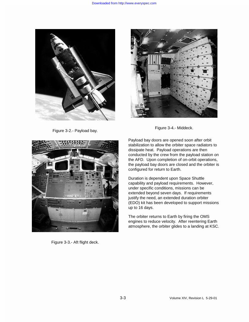
The orbiter payload bay is approximately 60feet long and 15 feet in diameter (Figure 3-2).Normally, several compatible payloads shareeach flight; occasionally, however, adedicated payload requires the entire payloadbay.
The flight crew normally consists of acommander, pilot, and three or more missionspecialist (MS) astronauts. Payloadspecialists (PSs) may be included to operatetheir experiments. The commander and pilotoperate the orbiter and manage orbitersystems, while the MSs accomplish missionobjectives and assist the commander andpilot with management of orbiter systems.The commander, pilot, and MSs are selectedby NASA on a career basis. One or morePSs may be added as required with approvalfrom the SSP. Detailed responsibilities ofMSs and PSs are tailored to meet therequirements of each mission; crew size istherefore a function of mission complexityand duration.
Displays and controls for payload operationsare located in the aft flight deck (AFD), whichis the upper level of the crew compartment(Figure 3-3). The middeck, locatedimmediately below the flight deck, providesthe crew living area and accommodations formiddeck payloads (Figure 3-4).
b. ET - The ET provides the orbiter mainpropulsion system with liquid hydrogen (fuel)and liquid oxygen (oxidizer). After cutoff ofthe SSMEs, the ET is jettisoned and breaksup in the atmosphere over remote oceanareas.
c. SRBs - Two SRBs are fired in parallel withthe SSMEs to provide initial ascent thrust.The SRBs are recovered after each flight,refurbished, and reused.
Downloaded from http://www.everyspec.com

3-2 Volume XIV, Revision L 5-29-01
Figure 3-1.- Space Shuttle system.
3.2 Typical Space ShuttleMission
Space Shuttle launches take place at KSC inFlorida. Missions are launched from KSC withorbital inclinations of 28.45, 39, 51.6, or 57degrees. Other inclinations must be evaluated ona case-by-case basis. The launch site hasspecialized vehicle processing and payloadinstallation and checkout facilities, trainedcheckout crews, and launch operations teams.
As depicted in the shuttle mission profile (Figure 3-5), the Space Shuttle is launched with all threeSSMEs operating in parallel with the SRBs. SRBseparation occurs approximately 2 minutes afterlaunch. After SRB separation, the orbiter and ETcontinue ascent, using the three main engines withmain engine cutoff (MECO) occurring about 8minutes after liftoff. Then the ET is separatedfrom the orbiter. After a short coasting period, theorbiter OMS engines are fired for additionalvelocity necessary to achieve proper orbit.
Downloaded from http://www.everyspec.com
3-3 Volume XIV, Revision L 5-29-01
Figure 3-2.- Payload bay.
Figure 3-3.- Aft flight deck.
Figure 3-4.- Middeck.
Payload bay doors are opened soon after orbitstabilization to allow the orbiter space radiators todissipate heat. Payload operations are thenconducted by the crew from the payload station onthe AFD. Upon completion of on-orbit operations,the payload bay doors are closed and the orbiter isconfigured for return to Earth.
Duration is dependent upon Space Shuttlecapability and payload requirements. However,under specific conditions, missions can beextended beyond seven days. If requirementsjustify the need, an extended duration orbiter(EDO) kit has been developed to support missionsup to 16 days.
The orbiter returns to Earth by firing the OMSengines to reduce velocity. After reentering Earthatmosphere, the orbiter glides to a landing at KSC.
Downloaded from http://www.everyspec.com

3-4 Volume XIV, Revision L 5-29-01
Figure 3-5.- Mission phases (typical).
3.3 Space Shuttle CargoCapability
Allowable cargo weight is influenced by variousoperational requirements that depend upon thetype of mission. Allowable cargo weight isconstrained by either ascent performance orlanding weight limits, and is affected by suchfactors as orbital altitude and inclination, missionduration, crew size, and rendezvous requirements.If payload requirements exceed the capabilitiesdescribed below, the customer should inform thePIM assigned to that particular payload (seesection 6).
3.3.1 Payload Control WeightDefinition
The weight of the payload itself, including anycarrier or booster, airborne support equipment(ASE), and payload-unique integration hardware, isconsidered payload control weight. This includesPSs and associated personnel provisions (500pounds per person). Payload control weight isspecified in the IP, and specific agreements forany control weight deviations must be negotiatedwith the SSP.
Downloaded from http://www.everyspec.com
4-1 Volume XIV, Revision L 5-29-01
Safety, Reliability, andQuality Assurance
4The payload customer is responsible for safety ofthe payload and its ground support equipment(GSE). The payload and GSE shall be designed tocomply with requirements of Safety Policy andRequirements for Payloads Using the SpaceTransportation System, NSTS 1700.7B, andSpace Transportation System Payload GroundSafety Handbook, 45 SPW HB S-100/KHB 1700.7.To assess compliance with safety requirements, amaximum of four safety reviews for the payload,GSE, and ground operations will be conducted bythe SSP in accordance with Payload SafetyReview and Data Submittal Requirements,NSTS/ISS 13830. Payload reliability and qualityare the responsibility of the customer.
The payload customer is responsible for thefollowing safety requirements:
a. Determination of hazardous aspects of thepayload and GSE during flight and groundoperations and implementation of requiredcorrective measures
b. Assurance of payload compatibility withSpace Shuttle interfaces
c. Identification of residual hazards andinterface incompatibilities prior to payloadsummary reviews and inspection
Preflight summary reviews and inspections ofpayloads may be conducted with participation bythe payload customer to verify that NASA safetyrequirements have been met.
Downloaded from http://www.everyspec.com

5-1 Volume XIV, Revision L 5-29-01
Payload Accommodations
5The Space Shuttle offers a wide range of payloadaccommodations and services. Additionalservices and accommodations are available on alimited basis through negotiation with the SSP.Detailed specifications and interfacecharacteristics of services are defined in ShuttleOrbiter/Cargo Standard Interfaces, ICD 2-19001.
For purposes of orientation, the orbiter/payloadinterface data contained in this document, itsappendixes, and its attachment are based on anorbiter-centered coordinate system as illustrated inFigure 5-1. Figure 5-2 identifies interfaces locatedon the external surfaces of the orbiter.
TYPE: ROTATING, ORBITER REFERENCED
ORIGIN: APPROXIMATELY 235 INCHES (5.97m) AHEADOF THE NOSE AND APPROXIMATELY 400INCHES (10.2m) BELOW THE CENTERLINE OFTHE PAYLOAD BAY
ORIENTATION AND LABELING:
THE X AXIS IS PARALLEL TO THE CENTERLINEOF THE PAYLOAD BAY, NEGATIVE IN THEDIRECTION OF LAUNCH
THE Z AXIS IS POSITIVE UPWARD IN LANDINGATTITUDE
THE Y COMPLETES THE RIGHT-HANDEDSYSTEM
THE STANDARD SUBSCRIPT IS 0
Figure 5-1.- Orbiter coordinate system.
5.1 Physical Accommodations
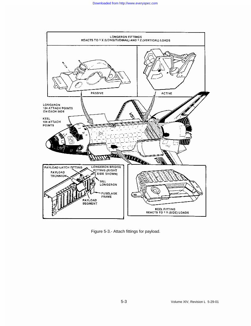
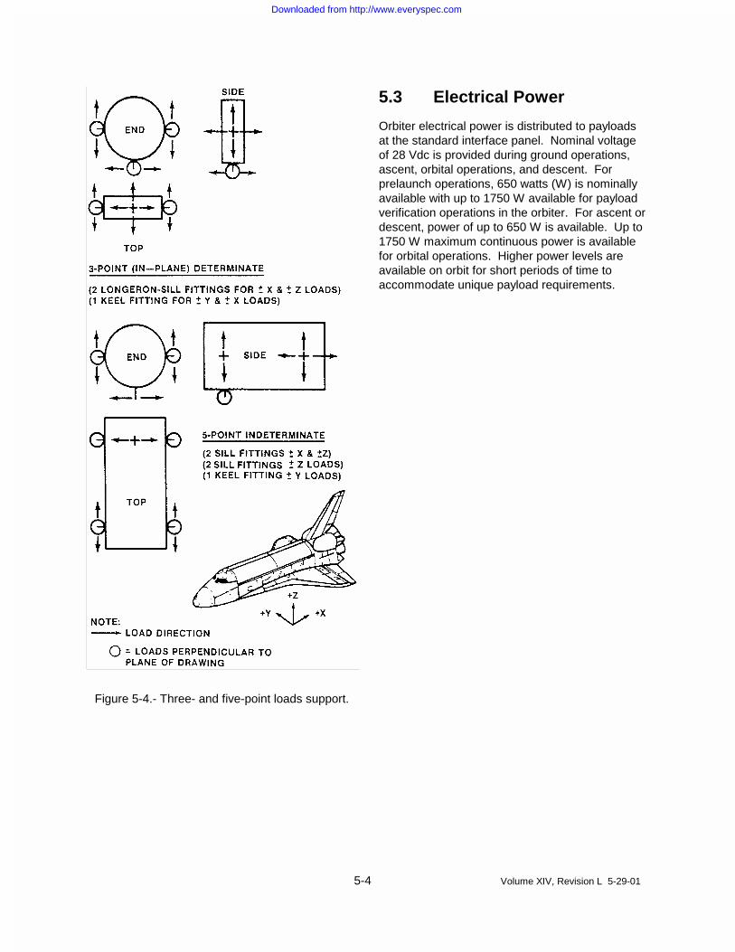
The orbiter has structural support attachmentpoints for payload trunnions along the length of thepayload bay as indicated in Figure 5-3. Payloadscan be supported by attach fittings at numerouspoints along both sides of the payload bay andalong the bottom at the orbiter keel centerline.Active fittings are used for deployable payloads.These attachment provisions support variouspayload designs by providing load reaction andstrain isolation between the orbiter and payload.The most common arrangements are three-pointand five-point designs (see Figure 5-4). Foradditional information, refer to Appendix 4.
5.2 Avionics Accommodations
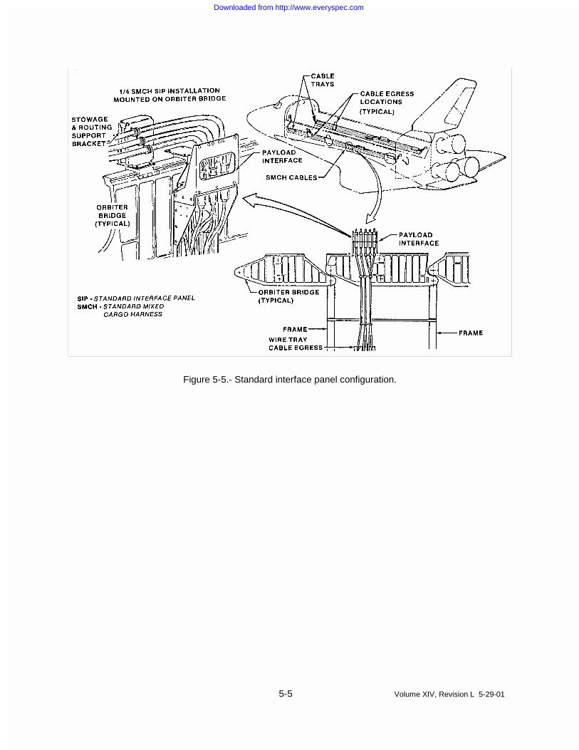
Avionics services including power, command, anddata are furnished to payloads using a standardmixed cargo harness (SMCH). The SMCH cablesare routed by payload wire trays on the port andstarboard sides of the payload bay. The SMCHprovides power interfaces on the starboard side ofthe payload, signal and control interfaces on theport side, and orbiter computer data bus interfaceson both port and starboard sides of the payload.The SMCH harness can egress the cable tray atessentially any location along the bay. The SMCHnormally egresses the cable tray at the payloadlocation in the bay and is routed to a standardinterface panel adjacent to the payload (Figure 5-6), minimizing the length of the customer-providedcable to the standard interface panel from thepayload. Figure 5-5 is a diagram of avionicsaccommodations for one of four primary payloads.
Downloaded from http://www.everyspec.com

5-2 Volume XIV, Revision L 5-29-01
Figure 5-2.- Payload umbilical service panels.
Downloaded from http://www.everyspec.com
5-3 Volume XIV, Revision L 5-29-01
Figure 5-3.- Attach fittings for payload.
Downloaded from http://www.everyspec.com
5-4 Volume XIV, Revision L 5-29-01
Figure 5-4.- Three- and five-point loads support.
5.3 Electrical Power
Orbiter electrical power is distributed to payloadsat the standard interface panel. Nominal voltageof 28 Vdc is provided during ground operations,ascent, orbital operations, and descent. Forprelaunch operations, 650 watts (W) is nominallyavailable with up to 1750 W available for payloadverification operations in the orbiter. For ascent ordescent, power of up to 650 W is available. Up to1750 W maximum continuous power is availablefor orbital operations. Higher power levels areavailable on orbit for short periods of time toaccommodate unique payload requirements.
Downloaded from http://www.everyspec.com
5-5 Volume XIV, Revision L 5-29-01
Figure 5-5.- Standard interface panel configuration.
Downloaded from http://www.everyspec.com

5-6 Volume XIV, Revision L 5-29-01
Figure 5-6.- Avionics provisions - standard accommodation.
5.4 Command Services
Command services for payloads can be providedfrom the orbiter, Mission Control Center-Houston(MCC-H), and payload operations controlcenters (POCCs). Ground-initiated commandsto attached or detached payloads aretransmitted through the orbiter communicationsystem. The crew can initiate commands
through the standard switch panel or entercommand instructions through the keyboard intothe orbiter avionics system, generatingcommands in the form of discretes or serialdigital signals. Standard accommodationsinclude the following command capabilities:
a. Hardwired commands from the standardswitch panel: Switch closure and/or 28 Vdc
Downloaded from http://www.everyspec.com

5-7 Volume XIV, Revision L 5-29-01
commands are provided at the standardswitch panel located at the payload stationon the AFD. The standard switch panel(Figure 5-7) provides 12 switches whichcan be operated on orbit by the crew.Overlay panels identify specific payloadfunctions.
b. Hardwired multiplexer/demultiplexer (MDM)commands from the orbiter: Discretecommands are provided at the payloadwiring interface by an orbiter MDM. Theyare issued by the orbiter general purposecomputer (GPC) in response to keyboardentries from the crew or commands fromthe Mission Control Center (MCC). Outputsignals provided are four discrete high-levelsignals (0 to 28 Vdc) and eight discrete low-level signals (0 to 5 Vdc).
c. Commands via the payload signalprocessor (PSP): Serial digital commandsto attached payloads may be providedthrough the PSP and can be generatedonboard the orbiter or from the MCC. TheMCC can store and generate payloadcommands as an optional service orforward commands generated at thecustomer POCC. Nine discrete data ratesup to 2000 bits/second and threenonreturn-to-zero (NRZ) data codes areavailable.
d. Commands via the payload data bus: Thestandard accommodation providesconnections to the payload data bus.Command data can be provided by theorbiter through a unique customer provideddata bus compatible interface (i.e., anMDM) connected to the orbiter data bus.This enables both onboard commandingand monitoring by the crew or operationfrom the MCC. Discrete outputs, pulseddiscrete outputs, and analog outputs can beprocessed.
e. Commands via the payload interrogator(PI): The PI provides an S-band radiofrequency (RF) link to command andmonitor detached payloads which arecompatible with the Deep Space Network(DSN) or Space Network (SN). Thecommand signal is on a 16 kHz subcarrierwhich is phase shift key (PSK) modulatedby the baseband command signal. Ninediscrete data rates up to 2000 bits/secondand three NRZ data codes are available.
f. Software for onboard-initiated singlecommands: The onboard commandprocessing capability provided as a part ofthe standard accommodation includesprovisions for initiating 40 singlecommands. These commands can beissued to a customer provided bus terminalunit, orbiter MDM, PSP, or PI.
Figure 5-7.- Standard switch panel.
Downloaded from http://www.everyspec.com
5-8 Volume XIV, Revision L 5-29-01
5.5 Data Processing andDisplay Services
Payload data processing and monitoring isavailable onboard the orbiter, at the MCC, and atcustomer POCCs. Payload telemetry is forwardedby orbiter communications systems to the MCCand customer POCCs. The Tracking and DataRelay Satellite System (TDRSS) is available for alarge percentage of each orbit. Each payload hasaccess to the following data processing anddisplay capabilities:
a. Hardwired displays from the standard switchpanel: The standard switch panel provides12 status indicators (talkbacks) to enable thecrew to monitor payload status and operation.These indicators are normally used duringactive crew control of payload operations andare not monitored during crew sleep periods.
b. Hardwired data and displays from the orbiterMDM: The MDM is capable of receiving eightdiscrete low level signals (0 to 5 Vdc) and twoanalog differential signals (0 to 5 Vdc) foronboard data processing or transmission toground stations. Analog and discrete payloadsignals received by the orbiter MDM can bemonitored onboard, at the MCC, and at thecustomer POCC. Signals “limit sensed” bythe orbiter GPC will visually or audibly notifythe crew when predetermined limits orconditions are exceeded.
c. Data and displays via the payload datainterleaver (PDI): Compatible payloadtelemetry data can be input to the PDI andforwarded to the customer POCC through theMCC. During ascent, telemetry may be sent tothe ground at a nominal rate of 1 kilobit/ secondper payload. Payload telemetry
sent to the ground will nominally be limited to8 kilobits/second per payload except when apayload is being deployed. During checkoutand deployment, a payload will normally belimited to a rate of 32 kilobits/second for up to20 minutes. During these periods, otherpayloads may transmit telemetry to theground at a nominal rate of 1 kilobit/secondeach. Onboard processing capability (8 bitwords) provides display and limit sensing forcrew monitoring and payload operation.
NRZ-level (NRZ-L) is the preferred coding;alternatively, biphase-L can be employed.
d. Data and displays via the data bus: Customerprovided data bus units compatible with theorbiter system can be connected to thepayload data bus to provide data acquisitionand processing for display to the crew.Discrete and/or analog data can also betransmitted to the MCC and forwarded to acustomer POCC.
e. Data and displays via the PI: Data fromdetached payloads are received by the PI,operating in DSN or SN modes. The orbitercan process detected data for display to thecrew or transmission to the MCC andforwarding to a POCC. The PI receives theRF carrier and detects a pulse codemodulated/ PSK 1.024-MHz subcarrier.Payload data can be received at one of fivediscrete rates up to 16 kilobits/second. NRZand biphase data codes are available.
f. Software for onboard data processing:Onboard data processing for up to 40discrete or analog parameters is provided asa standard service. Data may be acquired viathe PI, PDI, MDM, or a payload data bus unit.Data are displayed to the crew and may, inlimited quantities, be transmitted to the MCCand forwarded to a POCC.
5.6 Recording
Orbiter provides the Modular Memory Unit (MMU),a solid state recorder, for payload recording.Payload recorder accommodations include fourdigital recording inputs. Recording time is availableduring ascent, payload deployment, and descent.
5.7 Timing
Standard accommodations include one missionelapsed time (MET) signal and two Greenwichmean time (G.m.t.) signals in interrangeinstrumentation group B (IRIG-B) modified codeformat. See Appendix 3 for detailed electricalpower and avionics information.
Downloaded from http://www.everyspec.com

5-9 Volume XIV, Revision L 5-29-01
5.8 Thermal Accommodations
The Space Shuttle can provide thermalenvironments that meet requirements for mostpayloads. Prelaunch and postlanding payload baypurge provides limited thermal conditioning. Onorbit with the payload bay doors open, a widerange of thermal environments is possible and islimited by the attitude hold capability of the orbiterand payloads in the payload bay. Actual thermalenvironments depend upon numerous factorsincluding orbiter attitude sequence, orbiter-to-payload thermal interactions, and payload-to-payload thermal interactions.
For mixed cargo payloads, payload design must becompatible with standard payload bay purge andattitude requirements as defined in ICD 2-19001,which includes a nominal ground payload baypurge temperature of 65+/- 5 degrees F,continuous payload bay-to-earth attitude, 30minutes top sun, 90 minutes bay-to-space, and 6hours tail-to-earth (rendezvous attitude). SeeAppendix 2 for additional Space Shuttle thermalinformation.
5.9 Ground SupportEquipment Umbilical
The GSE umbilical, also known as the T-0umbilical, furnishes prelaunch payload monitoring,commanding, and low-level power requirements,and separates from the orbiter at liftoff.
5.10 Pointing
Pointing accuracy of the orbiter is dependent uponinertial measurement unit (IMU) alignment,structural alignment uncertainty, structural bendingdue to thermal distortions, selected DAP attitudedeadbands, etc., and thus changes throughout amission. However, for finite periods of time, theorbiter/ payload structural interface can bemaintained at an inertial attitude within plus orminus one degree for duration up to 1 hour.
5.11 Payload Deployment
Orbital parameters for payload deployment may bespecified by the customer as long as they complywith Space Shuttle constraints. The orbiter/payload structural interface can be pointed towithin one degree of the desired direction fordeployment. If the payload has a compatiblegrapple fixture, deployment can be accomplishedby payload ASE, the remote manipulator system(RMS) (see 5.6), or the stabilized payloaddeployment system (SPDS). If the RMS is usedfor deployment, the RMS payload/structuralinterface can be pointed within five degrees of thedesired deployment attitude.
5.12 Payload Bay SidewallMounted PayloadAccommodations
Payload accommodations are available to supportpayload bay payloads which do not require the fullrange of standard accommodations and aresidewall mounted. Detailed specifications ofservices and interface characteristics are definedin Shuttle/ Payload Interface Definition Documentfor Small Payload Accommodations, NSTS 21000-IDD-SML.
5.12.1 Physical Accommodations
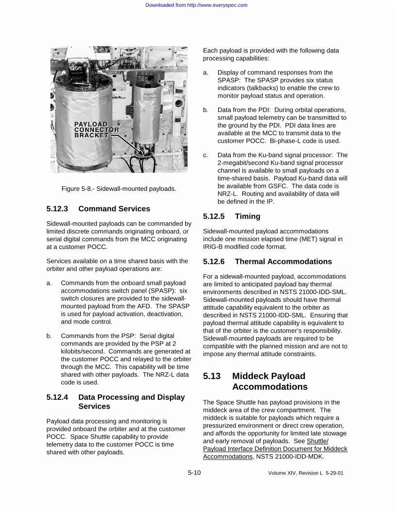
The payload is mounted on a sidewall payloadcarrier (Figure 5-8), which is available on the portor starboard side of the payload bay. Severalsidewall payload carriers are available and areselected based on the weight of the attachedpayload. The carriers span either the full bay,similar to the typical orbiter bridge shown in Figure5-3, or a partial span for light payloads. For moredetailed information, see Appendix 4.
5.12.2 Electrical Power
A maximum of 1400 W of nominal 28 Vdcelectrical power is available at the payloadinterface (either the payload connector bracket,Figure 5-8, or the standard interface panel, Figure5-5) for prelaunch checkout and orbital operations.These sidewall-mounted payloads may beconstrained to 300 W during other payloads highpower demand periods.
Downloaded from http://www.everyspec.com
5-10 Volume XIV, Revision L 5-29-01
Figure 5-8.- Sidewall-mounted payloads.
5.12.3 Command Services
Sidewall-mounted payloads can be commanded bylimited discrete commands originating onboard, orserial digital commands from the MCC originatingat a customer POCC.
Services available on a time shared basis with theorbiter and other payload operations are:
a. Commands from the onboard small payloadaccommodations switch panel (SPASP): sixswitch closures are provided to the sidewall-mounted payload from the AFD. The SPASPis used for payload activation, deactivation,and mode control.
b. Commands from the PSP: Serial digitalcommands are provided by the PSP at 2kilobits/second. Commands are generated atthe customer POCC and relayed to the orbiterthrough the MCC. This capability will be timeshared with other payloads. The NRZ-L datacode is used.
5.12.4 Data Processing and DisplayServices
Payload data processing and monitoring isprovided onboard the orbiter and at the customerPOCC. Space Shuttle capability to providetelemetry data to the customer POCC is timeshared with other payloads.
Each payload is provided with the following dataprocessing capabilities:
a. Display of command responses from theSPASP: The SPASP provides six statusindicators (talkbacks) to enable the crew tomonitor payload status and operation.
b. Data from the PDI: During orbital operations,small payload telemetry can be transmitted tothe ground by the PDI. PDI data lines areavailable at the MCC to transmit data to thecustomer POCC. Bi-phase-L code is used.
c. Data from the Ku-band signal processor: The2-megabit/second Ku-band signal processorchannel is available to small payloads on atime-shared basis. Payload Ku-band data willbe available from GSFC. The data code isNRZ-L. Routing and availability of data willbe defined in the IP.
5.12.5 Timing
Sidewall-mounted payload accommodationsinclude one mission elapsed time (MET) signal inIRIG-B modified code format.
5.12.6 Thermal Accommodations
For a sidewall-mounted payload, accommodationsare limited to anticipated payload bay thermalenvironments described in NSTS 21000-IDD-SML.Sidewall-mounted payloads should have thermalattitude capability equivalent to the orbiter asdescribed in NSTS 21000-IDD-SML. Ensuring thatpayload thermal attitude capability is equivalent tothat of the orbiter is the customer’s responsibility.Sidewall-mounted payloads are required to becompatible with the planned mission and are not toimpose any thermal attitude constraints.
5.13 Middeck PayloadAccommodations
The Space Shuttle has payload provisions in themiddeck area of the crew compartment. Themiddeck is suitable for payloads which require apressurized environment or direct crew operation,and affords the opportunity for limited late stowageand early removal of payloads. See Shuttle/Payload Interface Definition Document for MiddeckAccommodations, NSTS 21000-IDD-MDK.
Downloaded from http://www.everyspec.com

5-11 Volume XIV, Revision L 5-29-01
Change 1 07/27/01
5.13.1 Physical Accommodations
As shown in Figure 5-9, middeck payloads arestored in lockers which carry up to 54 pounds ofcargo and provide 2 cubic feet of volume. Trayswith dividers can be installed to separate eachlocker into as many as 16 compartments. Payloadhardware that replaces one or more lockers (butuses standard locker mounting locations) is alsoaccommodated.
5.13.2 Electrical Power
Up to 5 amperes (A) of nominal 28 Vdc power areavailable on orbit. Total power supplied to anypayload is limited to 115 W maximum continuousfor up to 8 hours, or 200 W peak for 10 seconds orless. Standard cables are available for routingpower from utility outlets to stowage locations.
Figure 5-9.- Middeck lockers.
5.12.3 Command and Monitoring
Normally, command and monitoring of middeckpayloads are limited to those controls, displays,and data collection features designed into thepayloads. As an optional service, the SSP canprovide a payload and general support computer(PGSC) to support inflight payload operations.The PGSC is a laptop computer that cancommunicate with payloads via recognizedstandards. For more information, seeShuttle/Payload Interface Definition Document forthe Payload and General Support Computer(PGSC), NSTS 21000-IDD-760XD.
5.13.4 Cooling
Payloads relying on dissipation of waste heat byfree convection heat transfer only (i.e., without theuse of a fan or similar means) are constrained by aheat load of 60 W for a standard stowage lockerand 15 W for payload equipment on an AFD panel.Payloads that are required to operate duringextravehicular activity (EVA) or EVA pre-breatheperiods shall design cooling based on a 10.2 psiacabin pressure.
When a payload provides an air circulation fanwhich discharges into the cabin, the maximum airoutlet temperature shall not exceed 120°F.External surface temperatures of payloadelements shall not exceed 120°F.
5.14 Get-Away Special PayloadAccommodations
The GAS program is managed by GSFC andoffers low cost access to a wide user community.It is an inexpensive method of gaining hands-onexperience in space research or testing ideas thatmight later evolve into major space experiments.
Standard GAS containers are provided in twovolumes: 5 cubic feet and 2.5 cubic feet.Payloads of up to 100 pounds can be housed inthe 2.5 cubic foot containers, and payloads up to200 pounds can be housed in the 5 cubic footcontainers. Since standard mechanical andelectrical interfaces are limited, all required battery,data recording, and sequencing systems areprovided by the customer. For technicalinformation, contact the Shuttle Small PayloadProjects Office (mail code 740) at GSFC.
5.15 Remote ManipulatorSystem
The RMS is a mechanical arm component of thepayload deployment and retrieval system (PDRS)used for payload deployment, retrieval, specialhandling operations, and other orbiter servicing. Itis 50 feet 3 inches in length and is mounted alongthe port longeron of the payload bay, outside a 15-foot diameter envelope reserved for cargo. Fordetails on PDRS capabilities and constraints, seeAppendix 8.
Downloaded from http://www.everyspec.com

6-1 Volume XIV, Revision L 5-29-01
Payload Integration Process
6The integration of payloads with the Space Shuttlegenerally follows the flow depicted
in Figure 6-1, and relates to the documentscontained in Figure 1-1.
IP ANNEXES
ENGINEERINGDESIGN
& ANALYSES
POSTFLIGHT HARDWARE & DATA DISTRIBUTION
FLIGHT READINESS REVIEW
PAYLOAD READINESS REVIEW ICD - INTERFACE CONTROL DOCUMENTOPS - OPERATIONSIP - INTEGRATION PLAN
PAYLOADSTRUCTURAL &
THERMAL MODELS
CARGO INTEGRATION REVIEW
ICDDEVELOPMENT
FLIGHT OPERATIONSREVIEW
NASA FORM1628
LAUNCH SERVICES AGREEMENT
FLIGHTVERIFICATION
ANALYSIS
FLIGHT DESIGN& FLIGHT OPS
IMPLEMENTATION LAUNCH/LANDINGSUPPORT
PREPARATION
PRELIMINARYFLIGHT
ASSIGNMENT
FLIGHT COMPATIBILITYASSESSMENT
INTEGRATION PLAN
Figure 6-1.- Payload integration process.
Downloaded from http://www.everyspec.com

6-2 Volume XIV, Revision L 5-29-01
6.1 Overview
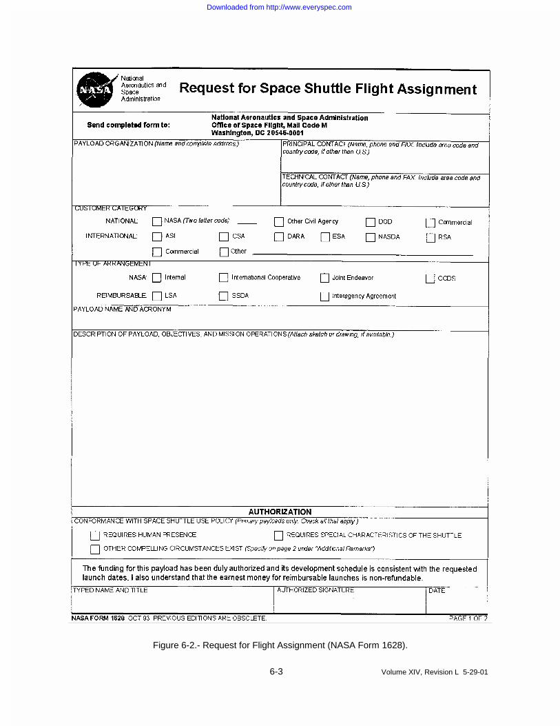
The first step in the integration process is for thecustomer or designated representative to submit aNASA Form 1628 (Figure 6-2) to NASAHeadquarters. Figure 6-1 depicts the integrationprocess from receipt of a Form 1628 to postflightdistribution of payload related hardware and data.
The integration process consists of two phasesprior to launch. The first is the development offormal agreements between the customer andNASA, and the second is the detailedimplementation of these agreements and plans.
The schedule during the first phase is determinedby payload development, but must be completed intime to support the Cargo Integration Review(CIR). Schedules are established by the SSPduring the second phase to meet the launch date.
Concurrent with these two phases of the payloadintegration process, safety reviews are normallyconducted at four levels of payload development.The JSC and KSC safety panels conduct safetyreviews (phase 0 through phase III) to assesssafety aspects of payload design, flight operations,GSE design, and ground operations. The depthand number of safety reviews are determined bythe SSP safety review panel chairman, inconjunction with the customer, and depend on thecomplexity, technical maturity, and hazard potentialof the payload.
6.2 Formal AgreementsDevelopment
Development of formal agreements between thecustomer and NASA is conducted byrepresentatives of NASA Headquarters, JSC, andKSC.
A NASA Form 1628 is submitted to NASAHeadquarters to be scheduled for a flight on theSpace Shuttle and to begin appropriate agreementnegotiations.
NASA Headquarters transmits the NASA Form1628 to JSC, where a detailed assessment of therequirements is conducted. Once requirementsare determined to be within the capabilities andconstraints of the Space Shuttle, a PIM is assignedto the customer and remains the customer’sprimary point of contact throughout the entireprocess. The PIM is responsible for ensuring thatcustomer requirements have been accuratelydefined and documented, are compatible withorbiter payload accommodations, and are properlyimplemented. The PIM also coordinates anyengineering or other technical support required atJSC. Additionally, an LSSM is assigned as thecustomer’s point of contact at the launch andlanding sites. The LSSM is responsible for LaunchSite Support Plan, IP Annex 8, and for payloadprocessing support at the launch and landing sites.
The PIM initiates a meeting with the customer toreview the integration process and familiarize thecustomer with JSC and KSC operations. Thecustomer provides a detailed description of theplanned payload, and formal development ofpayload requirements begins.
6.3 Documentation
The principal documents developed and employedduring the payload integration process is theindividual IP with appropriate IP annexes, and datasubmittals; and individual payload ICD.
When agreed to and signed by both the customerand NASA, the IP with its appropriate annexes anddata submittals; and the ICD become the technicalcontract. The IP also becomes part of the formallegal contract by direct reference in the NASAHeadquarters agreement.
Downloaded from http://www.everyspec.com
6-3 Volume XIV, Revision L 5-29-01
Figure 6-2.- Request for Flight Assignment (NASA Form 1628).
Downloaded from http://www.everyspec.com

6-4 Volume XIV, Revision L 5-29-01
Figure 6-2.- Request for Flight Assignment (NASA Form 1628) (concluded).
Downloaded from http://www.everyspec.com

6-5 Volume XIV, Revision L 5-29-01
Following acceptance of the payload, the payloadintegration process begins with development of aIP. The purpose of the IP is to:
a. Define SSP and customer responsibilities
b. Define the technical baseline forimplementation
c. Establish guidelines and constraints forintegration and planning
d. Define integration tasks to be accomplished
e. Establish interface verification requirements
(AS REQUIRED)
PAYLOAD ORBITERINTERFACECONTROL
DOCUMENT
PAYLOADINTERFACEDEFINITIONDOCUMENT
ANNEXBLANKBOOKS
STANDARDINTEGRATION
PLANS
INTEGRATIONPLAN
LAUNCHSERVICES
AGREEMENT
INTEGRATIONPLAN
ANNEXESAND DATA
(AS REQUIRED)
f. Establish operational services requirements
g. Establish controlling schedules for all majorintegration activities
h. Identify SSP flight and ground safetyrequirements
i. Establish the basis for SSP definition andpricing of optional services
Standard Integration Plans
SIPs are guides or “blank books” for thedevelopment of IPs. As outlined in Figure 1-1, anSIP has been developed for each generic type ofpayload (e.g., deployable, attached, etc.). The SIPcontains technical requirements, managementinterfaces, services, and schedules that apply tothat type of payload.
IP Annexes
The IP annexes specify the detailed technicalrequirements and data required to configure flightand ground systems and implement integrationfunctions as outlined in the IP. Generic annexeshave been developed to help the customerunderstand data requirements for each annex. Tobe considered binding on the SSP, allrequirements outlined in the annexes must bewithin the scope of the IP. Not all annexes arerequired for every payload and not all annexes aredocuments but may be data submittals. Theannexes are:
Annex 1: Payload Data Package – Contains thepayload configuration (including mechanicalelectrical power, and command interfacedrawings), weight and mass properties, avionics,and the physical function data for installation,deployment, and/or retrieval of the payload asrelated to the Orbiter. Annex 1 describes thepayload "as built" configuration and substantiatesthe agreed-to design of the interface controldocument (ICD).
Annex 2: Flight Planning - Includes data requiredto define electrical power and cooling profile,deployment/retrieval/proximity operationsrequirements, crew activity requirements, attitudeand pointing, geographical constraints data, andpointing/ timing data for deployment of upperstages.
Annex 3: Superceded by IP Table 8-1 datasubmittals.
Annex 4: Command and Data - Identifiesindividual commands required to operate thepayload, measurements of payload status andhealth, and measurements for accomplishingpayload objectives. Provides necessaryinformation for processing and interpreting data.
Downloaded from http://www.everyspec.com
6-6 Volume XIV, Revision L 5-29-01
Annex 5: Payload Operations Control Center(POCC) - Defines customer requirements leviedon the SSP for POCC, remote POCC, andcommunications resources.
Annex 6: Orbiter Crew Compartment wasreplaced with the Interface Control Agreement(ICA).
Annex 7: Training - Describes customer providedtraining of Space Shuttle personnel and POCCteam training requirements; determines integratedsimulation requirements, establishes trainingsequence flow, and provides payload trainingschedules.
Annex 8: Launch Site Support Plan - Definespayload processing flow at the launch site,customer launch and landing site nominal andcontingency support (e.g., scrub/turnaround, intactabort) requirements, and specifies launch sitefacilities and resources to meet customerrequirements.
Annex 9: Superceded by the Operations andMaintenance Requirements SpecificationsDocument (OMRSD).
Annex 11: Extravehicular Activity (EVA) - Definesspecific design configuration for each hardware-to-hardware and hardware-to-crew interfaceassociated with EVA support of a particularpayload, including scheduled, unscheduled, andcontingency EVA’s.
Interface Control Annex (ICA) - The Orbiter CrewCompartment ICA identifies customer-suppliedequipment stowed or installed in the crewcompartment and defines requirements affectingstowage, installation, handling, or crew use andproposed stowage/installation of payloadmaterials. The document includes display andcontrol and standard switch panel nomenclaturerequirements.
Operations and Maintenance RequirementsSpecification (OMRS) - The OMRSD File II,Volume 2 identifies projects level verificationagreements, payload-to-Space Shuttle ICDinterfaces to be verified, and the verificationmethod and location.
Time-Critical Ground Handling Requirements(TGHR) - The TGHR Table identifies mission-unique requirements for the time-critical ground
handling integration of Space Shuttle middeckpayloads.
Interface Control Document and InterfaceDefinition Document
The ICD defines detailed design interfacespecifications for each payload. An IDD has beendeveloped for each type of payload (standard,small, and middeck) to facilitate preparation of theICD; a dedicated payload will employ ICD 2-19001.
6.4 Payload ClassificationCriteria
a. Primary: A primary payload justifies a shuttlemission, either alone or in combination withother payloads, and meets the criteria of theshuttle use policy set forth in NMI 8610.12B,Policy for Obtaining Office of Space FlightProvided/Arranged Space TransportationService for NASA and NASA-RelatedPayloads, as determined by the NASA FlightAssignment Board and approved by theNASA Administrator. A primary payloadtypically defines the critical path of theintegration process, including KSCprocessing, flight design and missionoperations preparation, and postflightprocessing and data reduction.
b. Secondary payload: In general, a secondarypayload does not define the critical path ofthe integration process, but has requirementsthat use significant SSP resources. However,a combination of secondary payloads mayrepresent justification for a Shuttle mission inthe same sense as a primary payload. Asecondary payload, or combination ofsecondaries which define the critical path ofthe integration process, including KSCprocessing, flight design and missionoperations preparation, and postflightprocessing and data reduction will be treatedas a primary for manifesting purposes.
c. Middeck: A middeck is a payload which usesthe accommodations as defined in NSTS21000-SIP-MDK and/or NSTS 21000-IDD-MDK. In general, a middeck payload doesnot define the critical path of the integrationprocess, but has requirements that usesignificant SSP resources.
Downloaded from http://www.everyspec.com
6-7 Volume XIV, Revision L 5-29-01
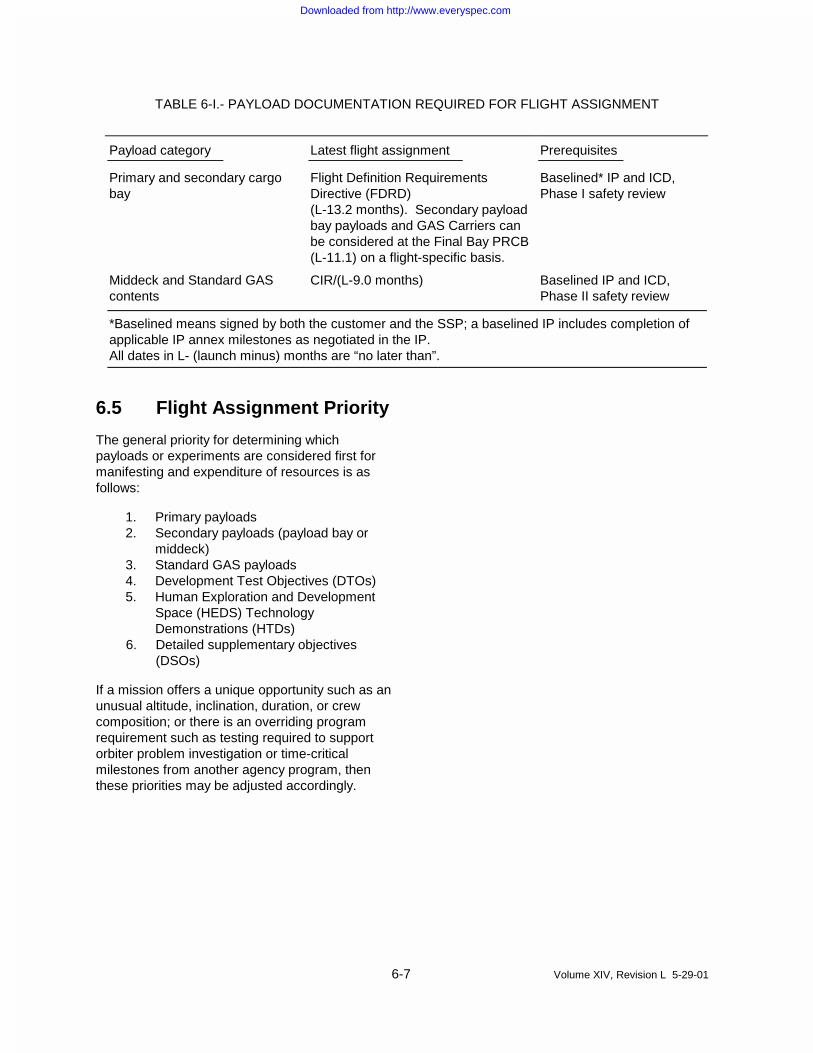
TABLE 6-I.- PAYLOAD DOCUMENTATION REQUIRED FOR FLIGHT ASSIGNMENT
Payload category Latest flight assignment Prerequisites
Primary and secondary cargobay
Flight Definition RequirementsDirective (FDRD)(L-13.2 months). Secondary payloadbay payloads and GAS Carriers canbe considered at the Final Bay PRCB(L-11.1) on a flight-specific basis.
Baselined* IP and ICD,Phase I safety review
Middeck and Standard GAScontents
CIR/(L-9.0 months) Baselined IP and ICD,Phase II safety review
*Baselined means signed by both the customer and the SSP; a baselined IP includes completion ofapplicable IP annex milestones as negotiated in the IP.All dates in L- (launch minus) months are “no later than”.
6.5 Flight Assignment Priority
The general priority for determining whichpayloads or experiments are considered first formanifesting and expenditure of resources is asfollows:
1. Primary payloads2. Secondary payloads (payload bay or
middeck)3. Standard GAS payloads4. Development Test Objectives (DTOs)5. Human Exploration and Development
Space (HEDS) TechnologyDemonstrations (HTDs)
6. Detailed supplementary objectives(DSOs)
If a mission offers a unique opportunity such as anunusual altitude, inclination, duration, or crewcomposition; or there is an overriding programrequirement such as testing required to supportorbiter problem investigation or time-criticalmilestones from another agency program, thenthese priorities may be adjusted accordingly.
Downloaded from http://www.everyspec.com
7-1 Volume XIV, Revision L 5-29-01
Cargo Integration andManifest Development
7The integration of a payload begins with thepreliminary flight assignment process andcontinues throughout requirements development.After submittal of preliminary annex data andcompletion of the ICD, a series of cargocompatibility assessments is performed. Theresults of these assessments are presented to thecustomer and SSP management at the CIR.
Flight Assignment
The flight assignment process begins when theNASA Form 1628 is received. The FlightAssignment Working Group (FAWG) assessescustomer requirements. Payloads with compatibleorbital requirements and configurations aremanifested together after the FAWG hasconsidered all applicable ground rules, constraints,and guidelines. A preliminary flight assignmentmanifest is reviewed by KSC to facilitatedevelopment of a viable launch site groundprocessing flow for establishing the launch date ofeach flight.
Flight Implementation Process
After formal agreements have been signed and apreliminary flight assignment released, NASAconducts preliminary cargo engineering analyses,ground operations planning, and mission planningto determine if the cargo elements are compatiblewith each other and with Space Shuttlecapabilities. To conduct these analyses, NASArequires certain design details for each payload,which are contained in the IP annexes and datasubmittals. The cargo engineering analysis andpreliminary flight analysis must be completed earlyenough in the integration process to allow SSPcompletion of required flight products andhardware details. Results of these analyses arepresented at the CIR. Each customer with apayload on the flight is required to participate inthis review to ensure that all requirements have
been satisfied. With the conclusion of the CIR,final preparation for the mission begins.
Flight Operations Preparation
Upon completion of final flight design and flightoperations planning products, and anymodifications (including software) required by theMCC, POCC, and crew training facilities, theseproducts are formally reviewed at the FlightOperations Review (FOR). The FOR supports thefinal phase of crew and flight operations personneltraining. The customer participates in periodicpayload reviews (by telecon and/or meeting)during preparation for flight.
Launch and Landing Site
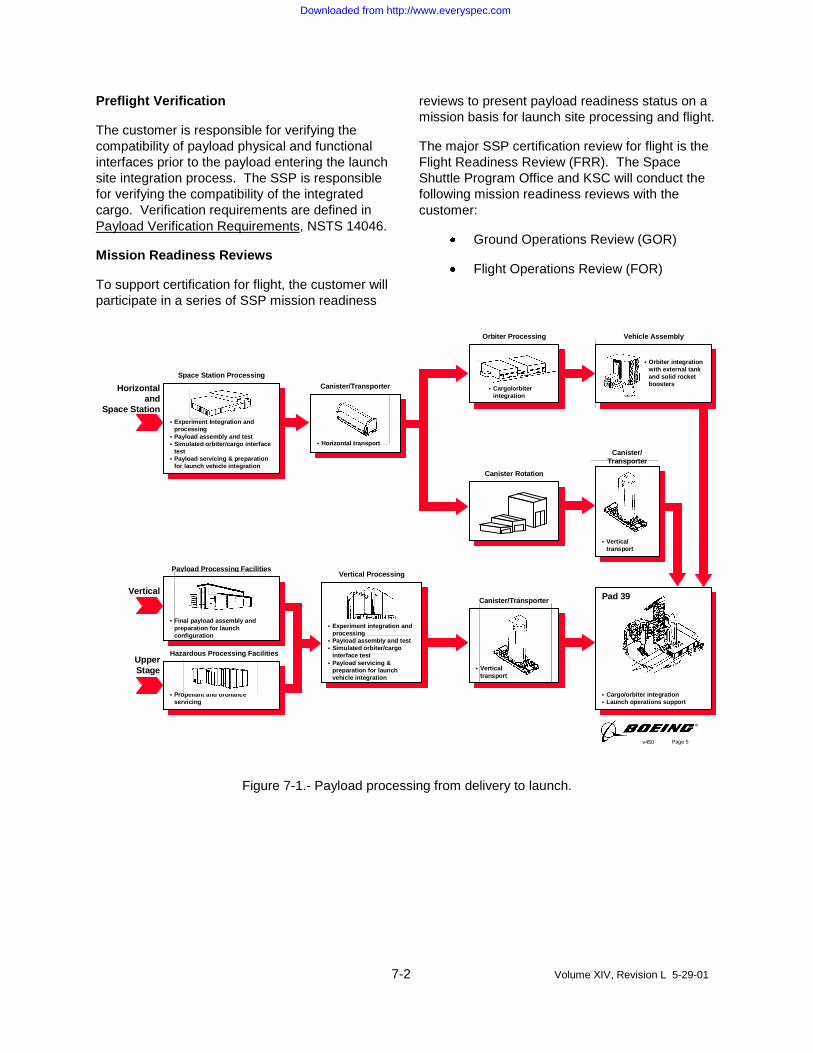
Payloads undergo final checkout, interfaceverification, and launch preparation at the launchsite. Standard facilities and services are allocatedon the basis of customer requirements (Figure 7-1). See Appendix 5 for more detail.
Payload processing generally begins with areceiving inspection at a KSC payload processingfacility (PPF). Additional payload processing mayrequire component or subsystem assembly (e.g.,mating to an upper stage or carrier, experimentintegration, etc.) After the payload is checked andserviced, it is moved to the payload integrationfacility for integration with other payloadsscheduled for the same flight.
The integrated payloads undergo interface andsystem verification testing and are installed in theorbiter, either horizontally in the OrbiterProcessing Facility (OPF) or vertically at thelaunch pad. Payload-to-orbiter interfaces are thenverified and the payload is configured for launch.After landing, the payload and/or payload ASE areremoved from the orbiter and prepared forshipment to a customer facility. For moreinformation, see Appendix 5.
Downloaded from http://www.everyspec.com
7-2 Volume XIV, Revision L 5-29-01
Preflight Verification
The customer is responsible for verifying thecompatibility of payload physical and functionalinterfaces prior to the payload entering the launchsite integration process. The SSP is responsiblefor verifying the compatibility of the integratedcargo. Verification requirements are defined inPayload Verification Requirements, NSTS 14046.
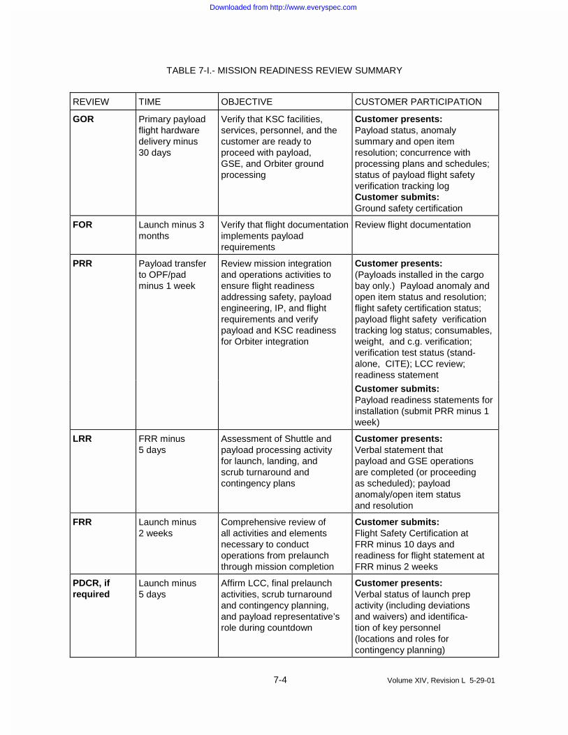
Mission Readiness Reviews
To support certification for flight, the customer willparticipate in a series of SSP mission readiness
reviews to present payload readiness status on amission basis for launch site processing and flight.
The major SSP certification review for flight is theFlight Readiness Review (FRR). The SpaceShuttle Program Office and KSC will conduct thefollowing mission readiness reviews with thecustomer:
x Ground Operations Review (GOR)
x Flight Operations Review (FOR)
Page 5v450
• Cargo/orbiterintegration
• Verticaltransport
Canister/Transporter
• Experiment Integration andprocessing
• Payload assembly and test• Simulated orbiter/cargo interface
test• Payload servicing & preparation
for launch vehicle integration
• Experiment integration andprocessing
• Payload assembly and test• Simulated orbiter/cargo
interface test• Payload servicing &
preparation for launchvehicle integration
• Propellant and ordnanceservicing
• Verticaltransport
• Orbiter integrationwith external tankand solid rocketboosters
• Cargo/orbiter integration• Launch operations support
Orbiter Processing Vehicle Assembly
Space Station Processing
Payload Processing Facilities
Canister Rotation
Canister/Transporter
Vertical Processing
• Final payload assembly andpreparation for launchconfiguration
Hazardous Processing Facilities
• Horizontal transport
Canister/TransporterHorizontaland
Space Station
Vertical
UpperStage
Pad 39
Figure 7-1.- Payload processing from delivery to launch.
Downloaded from http://www.everyspec.com
7-3 Volume XIV, Revision L 5-29-01
x Payload Readiness Review (PRR)
x Launch Readiness Review (LRR)
x FRR
x Payload Director's Countdown Review, ifrequired
x Prelaunch Mission Management (MMT)Review (L-1 or L-2 Days)
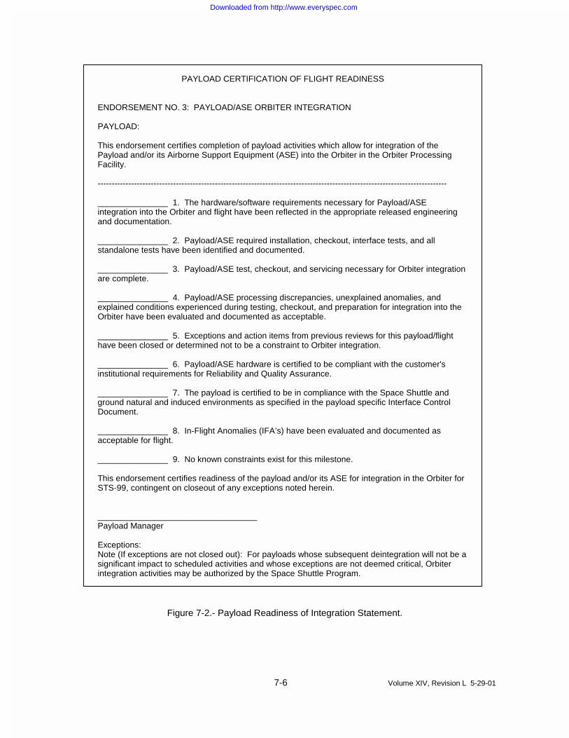
Table 7-I summarizes mission readiness reviewsand customer participation for a typical primarypayload. When a payload has limited SpaceShuttle interfaces and services, customerparticipation may be appropriately reduced asagreed to in the IP. See Figures 7-2 through 7-4for contents of the required payload readinessstatements.
Integrated Cargo Hazard Assessment
The SSP prepares a Generic Integrated CargoHazard Assessment Report (GICHAR), NSTS21111, that ensures safe interaction of the cargomix. Normally, the customer is not required toprovide any additional data; however, the customerwill be notified if more data or analyses arerequired.
Launch Commit Criteria
The customer must develop and negotiate LCCwith the SSP for all payloads with launchcountdown monitoring requirements. These LCCwill be developed in accordance with therequirements, groundrules, and constraints inAppendix 5.
Customer Participation During the Mission
The customer will have technical and managementrepresentatives at KSC during ground operationsplanning, preflight verification, launch, andpostlanding operations.
The Mission Management Team (MMT) willfunction as a program level oversight group toreview the status of the countdown and flightactivities and to make programmatic decisionsoutside the authority of the launch and flight teams.The customer's interface to the MMT is throughmembership on the Cargo Management Team(CMT). This team consists of SSP and customermanagement representatives who have the
authority and technical knowledge to make finalprogrammatic recommendations to the MMT onissues that affect the payload.
The customer is encouraged to have a customerrepresentative in the Customer Support Room(CSR) at the MCC during the flight. In addition tocustomer support at JSC, data can be routed toPOCC’s at various locations. POCC’s cancommand and control payload operations andreceive payload data.
Before a mission, the customer participates incontrol team training, consisting of briefings andsimulations. Simulations usually begin two monthsbefore launch and include a fully staffed MCC,Shuttle Mission Simulator (SMS) and crew, andremote POCCs, if applicable. During simulations,customers participate in training sessions torehearse various mission events.
Downloaded from http://www.everyspec.com
7-4 Volume XIV, Revision L 5-29-01
TABLE 7-I.- MISSION READINESS REVIEW SUMMARY
REVIEW TIME OBJECTIVE CUSTOMER PARTICIPATION
GOR Primary payloadflight hardwaredelivery minus30 days
Verify that KSC facilities,services, personnel, and thecustomer are ready toproceed with payload,GSE, and Orbiter groundprocessing
Customer presents:Payload status, anomalysummary and open itemresolution; concurrence withprocessing plans and schedules;status of payload flight safetyverification tracking logCustomer submits:Ground safety certification
FOR Launch minus 3months
Verify that flight documentationimplements payloadrequirements
Review flight documentation
PRR Payload transferto OPF/padminus 1 week
Review mission integrationand operations activities toensure flight readinessaddressing safety, payloadengineering, IP, and flightrequirements and verifypayload and KSC readinessfor Orbiter integration
Customer presents:(Payloads installed in the cargobay only.) Payload anomaly andopen item status and resolution;flight safety certification status;payload flight safety verificationtracking log status; consumables,weight, and c.g. verification;verification test status (stand-alone, CITE); LCC review;readiness statement
Customer submits:Payload readiness statements forinstallation (submit PRR minus 1week)
LRR FRR minus5 days
Assessment of Shuttle andpayload processing activityfor launch, landing, andscrub turnaround andcontingency plans
Customer presents:Verbal statement thatpayload and GSE operationsare completed (or proceedingas scheduled); payloadanomaly/open item statusand resolution
FRR Launch minus2 weeks
Comprehensive review ofall activities and elementsnecessary to conductoperations from prelaunchthrough mission completion
Customer submits:Flight Safety Certification atFRR minus 10 days andreadiness for flight statement atFRR minus 2 weeks
PDCR, ifrequired
Launch minus5 days
Affirm LCC, final prelaunchactivities, scrub turnaroundand contingency planning,and payload representative’srole during countdown
Customer presents:Verbal status of launch prepactivity (including deviationsand waivers) and identifica-tion of key personnel(locations and roles forcontingency planning)
Downloaded from http://www.everyspec.com

7-5 Volume XIV, Revision L 5-29-01
REVIEW TIME OBJECTIVE CUSTOMER PARTICIPATION
PrelaunchMissionManagementTeam (MMT)L-2 day
Launch minus2 days
Affirm final checkoutactivities and launchpreparations (includingcloseout of FRR actionitems and LCC changes)
As required for payload anomalies
Downloaded from http://www.everyspec.com
7-6 Volume XIV, Revision L 5-29-01
PAYLOAD CERTIFICATION OF FLIGHT READINESS
ENDORSEMENT NO. 3: PAYLOAD/ASE ORBITER INTEGRATION
PAYLOAD:
This endorsement certifies completion of payload activities which allow for integration of thePayload and/or its Airborne Support Equipment (ASE) into the Orbiter in the Orbiter ProcessingFacility.
-----------------------------------------------------------------------------------------------------------------------------
_______________ 1. The hardware/software requirements necessary for Payload/ASEintegration into the Orbiter and flight have been reflected in the appropriate released engineeringand documentation.
_______________ 2. Payload/ASE required installation, checkout, interface tests, and allstandalone tests have been identified and documented.
_______________ 3. Payload/ASE test, checkout, and servicing necessary for Orbiter integrationare complete.
_______________ 4. Payload/ASE processing discrepancies, unexplained anomalies, andexplained conditions experienced during testing, checkout, and preparation for integration into theOrbiter have been evaluated and documented as acceptable.
_______________ 5. Exceptions and action items from previous reviews for this payload/flighthave been closed or determined not to be a constraint to Orbiter integration.
_______________ 6. Payload/ASE hardware is certified to be compliant with the customer'sinstitutional requirements for Reliability and Quality Assurance.
_______________ 7. The payload is certified to be in compliance with the Space Shuttle andground natural and induced environments as specified in the payload specific Interface ControlDocument.
_______________ 8. In-Flight Anomalies (IFA’s) have been evaluated and documented asacceptable for flight.
_______________ 9. No known constraints exist for this milestone.
This endorsement certifies readiness of the payload and/or its ASE for integration in the Orbiter forSTS-99, contingent on closeout of any exceptions noted herein.
__________________________________Payload Manager
Exceptions:Note (If exceptions are not closed out): For payloads whose subsequent deintegration will not be asignificant impact to scheduled activities and whose exceptions are not deemed critical, Orbiterintegration activities may be authorized by the Space Shuttle Program.
Figure 7-2.- Payload Readiness of Integration Statement.
Downloaded from http://www.everyspec.com
7-7 Volume XIV, Revision L 5-29-01
PAYLOAD CERTIFICATION OF FLIGHT READINESS
ENDORSEMENT NO. 6: FLIGHT READINESS
PAYLOAD:This endorsement certifies readiness and worthiness of the payload as of the FRR.----------------------------------------------------------------------------------------------------------------------------
_____________ 1. All exceptions and action items from previous reviews for this payload havebeen closed/resolved.
_____________ 2. All payload requirements, analyses, and assessments have been defined inthe IP and its annexes and released to support the flight. (All TBD’s andTBR’s have been resolved.)
_____________ 3. All payload stand-alone readiness checkout has been successfullycompleted in accordance with the element and integrated OMRSD.
_____________ 4. All flight and ground hardware/software anomalies, including previous in-flight anomalies applicable to this flight and anomalies identified duringpayload installation and checkout, have been resolved or accepted. Alloperational workarounds to “fly as is” anomalies have been developed andverified.”
_____________ 5. All payload installation and interface checkout have been successfullycompleted in accordance with the payload installation and checkoutrequirements.
_____________ 6. The as-built payload configuration satisfies the released drawingrequirements.
_____________ 7. Flight design assessments have been accomplished per the IP integrationschedule, and products have been verified and delivered.
_____________ 8. The payload LCC minimum equipment list and mandatory instrumentationlists have been provided.
_____________ 9. No known constraints exist for this payload.
_____________ 10. Applicable SSP Operational Flight Rules have been reviewed and concurredwith for flight.
_____________ 11. Applicable sections of the Flight Data File have been reviewed andconcurred with for flight.
All payload-produced payload Flight Data File (PFDF) articles have beenvalidated and are ready for flight. All PFDF articles are consistent with theCrew Procedures Management Plan, Appendix F, Space Shuttle Flight DataFile Preparation Standards or equivalent.
Figure 7-3.- Payload Readiness for Flight Statement.
Downloaded from http://www.everyspec.com
7-8 Volume XIV, Revision L 5-29-01
_____________ 12. All payload operations control center (POCC) facilities and/or customerprovided ground support equipment (GSE) are ready to support the flight.
_____________ 13. All payload personnel supporting real-time operations have completedapplicable training and/or certification programs and are prepared to supportreal-time operations in accordance with applicable Joint Operations InterfaceProcedures and Flight Rules.
_____________ 14. All payload personnel with ground command responsibility are aware of thefunction, utilization and constraints associated with all of the commands intheir inventory.
_____________ 15. All customer provided payload training sessions for the flight crew and flightcontrollers have been successfully completed in accordance with theagreements described in the IP. The flight crew is certified to operate thepayload.
_____________ 16. All payload safety hazard controls have been implemented and verified, orare scheduled for implementation and will be tracked via the VerificationTracking Log.
_____________ 17. The in-cabin payload hardware is certified acceptable for toxicologicaleffects on the crew. Any changes to the configuration which affect thetoxicological assessment will be/have been reported to the SSP per JSC25607, “Requirements for Submission of Test Sample Materials Data forShuttle Payload Safety Evaluations.”
_____________ 18. The final weight and mass properties of the payload, as installed in theOrbiter, have been incorporated into the IP Annex 1, Payload Data Package.
This endorsement certifies payload readiness for the STS-XX mission, contingent on closeout ofany exceptions noted herein.
___________________________________Payload Manager
Exceptions:
Figure 7-3.- Payload Readiness for Flight Statement. (concluded)
Downloaded from http://www.everyspec.com
7-9 Volume XIV, Revision L 5-29-01
PAYLOAD CERTIFICATION OF FLIGHT READINESS
ENDORSEMENT NO. 6M: ORBITER MIDDECK FLIGHT READINESS
PAYLOAD:
This endorsement certifies the flight readiness and worthiness of the Middeck Payload.------------------------------------------------------------------------------------------------------------------------
_____________ 1. For payloads with prepack requirements, the appropriate hardware has beendelivered to the Flight Equipment Processing Contractor.
_____________ 2. For payloads replacing lockers, fit checks, as required, have been accomplished.
_____________ 3. All flight and ground hardware/software anomalies, including previous in-flightanomalies applicable to this flight and anomalies identified during payloadinstallation and checkout, have been resolved or accepted. All operationalworkarounds to “fly as is” anomalies have been developed and verified.
_____________ 4. Applicable SSP Operational Flight Rules have been reviewed and concurred withfor flight.
_____________ 5. Applicable sections of the Flight Data File have been reviewed and concurredwith for flight.
_____________ 6. All payload operations control center (POCC) facilities and/or customer providedground support equipment (GSE) are ready to support the flight.
_____________ 7. All payload personnel supporting real-time operations have completed applicabletraining and/or certification programs and are prepared to support real-timeoperations in accordance with applicable Joint Operations Interface Proceduresand Flight Rules.
_____________ 8. All payload personnel with ground command responsibility are aware of thefunction, utilization and constraints associated with all of the commands in theirinventory.
_____________ 9. All customer provided payload training sessions for the flight crew and flightcontrollers have been successfully completed in accordance with the agreementsdescribed in the IP. The flight crew is certified to operate the in-cabin payload.
_____________ 10. All payload safety hazard controls have been implemented and verified, or arescheduled for implementation and will be tracked via the Verification TrackingLog.
_____________ 11. The in-cabin payload hardware is certified to be acceptable for toxicologicaleffects on the crew. Any changes to the configuration which affect thetoxicological assessment will be/have been reported to the SSP per JSC 25607,“Requirements for Submission of Test Sample Materials Data for Shuttle PayloadSafety Evaluations.”
_____________ 12. No known constraints exist for this milestone.
This endorsement certifies the payload flight readiness for the STS- mission, contingent on closeout ofany exceptions noted herein.
___________________________________Payload Manager
Exceptions:
Figure 7-4.- Payload Readiness Statement for Middeck.
Downloaded from http://www.everyspec.com

8-1 Volume XIV, Revision L 5-29-01
Customer Funded Services
8NASA Space Shuttle services are provided topayload programs and customers as eitherstandard or customer-funded services. Themajority of costs for Space Shuttle services areincluded in the standard flight price. Theserepresent the cost to NASA for performing standardintegration tasks and launch services required byall payloads. Customer-funded services are thoseadditional services which may be required to fulfill acustomer’s unique payload requirements. Prior toinitiation of individual customer-funded services,the performing NASA organization and thecustomer will jointly scope the tasks and theperforming organization will establish the estimateof government costs and provide it to the customer.The customer-funded services will be agreed toand documented in the customer's integration plan.
Downloaded from http://www.everyspec.com
9-1 Volume XIV, Revision L 5-29-01
Acronyms and Abbreviations
9A ampere(s)ac alternating currentAFD aft flight deckASE airborne support equipment
c.g. center of gravityCIP Carrier Integration PlanCIR Cargo Integration ReviewCITE cargo integration test equipmentCMT Cargo Management TeamCO2 carbon dioxideCoFR Certification Flight ReadinessCSR Customer Support Room
dc direct currentDSN Deep Space NetworkDSO detailed supplementary objectiveDTO development test objective
ET external tankEVA extravehicular activity
FAWG Flight Assignment Working GroupFDRD Flight Definition and
Requirements DirectiveFOR Flight Operations ReviewFRR Flight Readiness Review
g gravityG.m.t. Greenwich mean timeGAS Get-Away SpecialGOR Ground Operations ReviewGPC general purpose computerGSE ground support equipmentGSFC Goddard Space Flight Center
HTD Human Exploration andDevelopment Space (HEDS)Technology Demonstrations
ICA Interface Control AnnexICD interface control documentICHA Integrated Cargo Hazard
AssessmentIDD interface definition documentIFA Inflight AnomalyIMU inertial measurement unit
in. inchesIP Integration PlanIRIG-B interrange instrumentation
group B
JEA joint endeavor agreementJSC Lyndon B. Johnson Space Center
kHz kilohertzKSC John F. Kennedy Space CenterKu-band 10.9 to 36 gigahertz per second
L- launch minusLCC launch commit criteriaLRR Launch Readiness ReviewLSA launch services agreementLSSM launch site support manager
m meter(s)MCC Mission Control CenterMCC-H Mission Control Center-HoustonMDM multiplexer/demultiplexerMECO main engine cutoffMET mission elapsed timeMHz megahertzMIP Mission Integration PlanMMT Mission Management TeamMMU Modular Memory UnitMOU memorandum of understandingMS mission specialistMSFC George C. Marshall Space Flight
Center
NASA National Aeronautics and SpaceAdministration
NRZ nonreturn-to-zeroNRZ-L nonreturn-to-zero-level
OMRS Operations and MaintenanceRequirements and Specification
OMRSD Operations and MaintenanceRequirements and SpecificationDocument
OMS orbital maneuvering systemOPF Orbiter Processing Facility
PDI payload data interleaver
Downloaded from http://www.everyspec.com

9-2 Volume XIV, Revision L 5-29-01
PF-1 payload forward-1PFDF payload flight data filePGSC payload and general support
computerPI payload interrogatorPIM payload integration managerPIP payload integration planPL REC payload recorderPMCR Payload Management Countdown
ReviewPOCC payload operations control centerPPF Payload Processing FacilityPRCB Program Requirements Control
BoardPRR Payload Readiness ReviewPS payload specialistPSK phase shift keyPSP payload signal processor
RCRS regenerable CO2 removal systemRCS reaction control systemRF radio frequencyRMS remote manipulator systemROEU remotely operated electrical
umbilicalRSS Rotating Service Structure
S-band 1.55 to 5.2 gigahertz per secondSIP standard integration planSMCH standard mixed cargo harnessSMS Shuttle Mission SimulatorSN Space networkSPA small payload accommodationsSPASP small payload accommodations
switch panelSPDS stabilized payload deployment
systemSRB solid rocket boosterSSME Space Shuttle main engineSSP Space Shuttle ProgramSSPF Space Station Processing Facility
TDRSS Tracking and Data Relay SatelliteSystem
TGHR Time Critical Ground HandlingRequirements
TP turbopump
U.S. United States
VA voltampere(s)Vac volts alternating currentVdc volts direct current
Downloaded from http://www.everyspec.com
10-1 Volume XIV, Revision L 5-29-01
Glossary
10Attached payload:Payload which remains in the payload bay and isnot deployed on orbit.
Cargo:Total complement of payloads (one or more) onany one flight. Cargo includes everything containedin the payload bay plus equipment, hardware, andconsumables located elsewhere in the orbiterwhich are unique to the user.
Command services:Command services include onboard discrete andPOCC serial digital commands.
Customer:An organization or individual requiring SpaceShuttle services.
Dedicated mission:A mission which, because of size, weight, or otherconsiderations, is devoted to a single payload.
Deep Space Network:Communications network managed by the JetPropulsion Laboratory for command and control ofall planetary flights.
Deployment:The process of removing a payload from a stowedor berthed position in the payload bay and releasingit to a position free of the orbiter.
Detached payload:A payload which is deployed from the payload bayon orbit.
Edwards Air Force Base:Secondary landing site for shuttle flights.
European Space Agency:An international organization acting on behalf of itsmember states (Belgium, Denmark, France,Germany, Italy, the Netherlands, Spain, Sweden,Switzerland, and the United Kingdom). The ESAdirects the development and manufacture ofSpacelab.
External tank:Element of the Space Shuttle which contains liquidpropellant and oxidizer for the orbiter main engines.It is jettisoned before orbit insertion.
Extravehicular activity:Activities by crewmembers conducted outside thespacecraft pressure hull or within the payload baywhen the payload bay doors are open.
Flight:The period from launch to landing of an orbiter.One flight may contain more than one payload ormore than one flight might be required toaccomplish a single mission.
Flight design:The trajectory, consumables, attitude and pointing,and navigation analyses necessary to support flightplanning.
Flight manifest:The designation of a flight, assignment of the cargoto be flown, and specific implementing instructionsfor Space Shuttle operations personnel.
Get-Away Special:Small payloads mounted in canisters in the payloadbay.
Grapple fixture:Structural fitting on a detached payload to mate it tothe RMS end effector.
Downloaded from http://www.everyspec.com

10-2 Volume XIV, Revision L 5-29-01
Inclination:The maximum angle between the plane of the orbitand the equatorial plane.
Induced environments:Environments resulting from orbiter operation suchas acceleration, vibration, acoustics, etc.
Inertial upper stage:Solid propulsive upper stage designed to placespacecraft on high Earth orbits or on escapetrajectories for planetary missions.
Integration:A combination of activities and processes toassemble payload and Space Shuttle components,subsystems, and system elements into a desiredconfiguration and verify compatibility.
Interface:The mechanical, electrical, and operationalcommon boundary between two elements of asystem.
Interface verification:Flight hardware interface testing by an acceptablemethod to confirm compatibility with affectedelements of the Space Shuttle.
Ku-band signal processor:Instrument that receives high data rate scientificdata from small payloads in the payload bay andtransfers it to the orbiter communication system.
Launch pad:The area where the stacked Space Shuttleundergoes final prelaunch checkout and countdownand is then launched.
Launch site support manager:The single point of contact for arranging payloadprocessing at the launch and landing site.
Load factors:Measurements used in determining the pricecharged to a customer.
Middeck payload:Payload or experiment requiring pressurized crewcompartment accommodations.
Mission:The performance of a coherent set of investigationsor operations in space to achieve program goals. Asingle mission might require more than one flight,
or more than one mission might be accomplishedon a single flight.
Mission Control Center-Houston:JSC facility for control and support of all phases ofSpace Shuttle flights after launch.
Mission phases:Prelaunch, ascent, on orbit, deorbit, entry, landing,and postflight.
Mission specialist:Crewmember responsible for coordination ofoverall payload/Space Shuttle interaction; directsallocation of Space Shuttle and crew resources toaccomplish combined payload objectives.
Mission station:Location on the AFD where payload supportoperations are performed, usually by the missionspecialist.
Mixed payloads:Cargo containing more than one type of payload.
Multiplexer/demultiplexer:A data acquisition, distribution, and signalconditioning unit. It converts serial digitalinformation from the GPC to analog and discreteoutputs for payload operations, and acquiresanalog and discrete signals from the payload andconverts them to serial digital signals for onboardprocessing by the orbiter GPC.
Optional service:Additional services and accommodations availableat additional charges.
Orbiter:The manned orbital flight vehicle of the SpaceShuttle.
Orbital maneuvering system:Orbiter engines that provide thrust to perform orbitinsertion, circularization, transfer, rendezvous, anddeorbit.
Orbiter Processing Facility:Building at KSC with two high bays in which theorbiter undergoes postflight inspection,maintenance, and premate checkout beforepayload installation. Payloads are also installedhorizontally in the orbiter in this building.
Downloaded from http://www.everyspec.com
10-3 Volume XIV, Revision L 5-29-01
Payload:The total complement of specific instruments,space equipment, support hardware, andconsumables carried in the orbiter (but not includedas part of basic orbiter payload support) toaccomplish a discrete activity in space.
Payload bay:The unpressurized midsection of the orbiterfuselage behind the cabin aft bulkhead. Maximumusable payload envelope is approximately 15 feet(4.6 m) in diameter and 60 feet (18.3 m) in length.The payload bay doors extend the full length of thebay.
Payload carrier:Used with the Space Shuttle to obtain low-costpayload operations. Payload carriers are habitablemodules (Spacelab) and attached but uninhabitablemodules (pallets, free-flying systems, satellites, andupper stages).
Payload data bus:Provides compatible interface matching, isolation,and fault protection to allow the payload busterminal unit and orbiter GPC to operate as a digitaltransmission system.
Payload data interleaver:Provides the interface for acquiring asynchronouspulse code modulation (PCM) telemetry fromattached and detached payloads.
Payload interrogator:Provides RF communications between the orbiterand detached payloads.
Payload Operations Control Center:Ground facility where payload operations aremonitored and controlled.
Payload recorder:Receives analog or digital data from attachedpayloads for limited periods of time.
Payload signal processor:Transmits serial digital commands to one detachedpayload from the PI or one attached payloadselected by the crew or a ground station.
Payload specialist:Crewmember responsible for operation andmanagement of experiments or other payloadelement assignments.
Payload station:Location on the AFD where payload-specificfunctions are performed, usually by a payload ormission specialist.
Postretrieval:Activities after a payload has been returned andsecured in the payload bay.
Remote manipulator system:Mechanical arm on the payload bay longeroncontrolled from the AFD to deploy, retrieve, ormove payloads.
Retention latches:Longeron and keel fittings providing structuralretention of payloads in the payload bay.
Retrieval:The process of using the RMS and/or otherhandling aids to return a captured payload to astowed or berthed position. No payload isconsidered retrieved until it is fully stowed for a safereturn or berthed for repair and maintenance tasks.
Rotating Service Structure:The RSS is the launch pad service structureincluding the Payload Changeout Room (PCR)which rotates out to the orbiter on the mobilelaunch platform (MLP).
Solid rocket boosters:Two solid rocket motors which augment ascentthrust at launch.
Spaceflight Tracking and Data Network:Ground-based stations in direct communicationwith NASA flight vehicles.
Spacelab:A general purpose orbiting laboratory for mannedand automated activities in near-Earth orbit. Itincludes both module and pallet sections, whichcan be used separately or in several combinations.
Space radiators:Thermal radiating panels on the inside of the orbiterpayload bay doors which may be extended on orbit.
Downloaded from http://www.everyspec.com
10-4 Volume XIV, Revision L 5-29-01
Space Shuttle:A vehicle consisting of an orbiter, external tank,and two SRB’s.
Space Shuttle Program:The Space Shuttle vehicle and the programorganization, management, systems, personnel,and facilities which support its design andoperation.
Standard payload:A payload installed in the payload bay usingstandard payload accommodations.
Standard switch panel:Provides switch closure and/or 28 Vdc commandsand status indicators for payload operation andstatus monitoring.
Tracking and Data Relay Satellite System:A satellite communication system providingprincipal coverage from geosynchronous orbit forall flights.
Upper stage:Upper stages are designed for launch from thepayload bay with propulsive elements to deliverpayloads into orbits and trajectories beyond thecapabilities of the shuttle.
Downloaded from http://www.everyspec.com
Related Documents