Connecting What’s Needed with What’s Next ™ oceaneering.com Nozzle Check Valve High-performance check valves FEATURES Low pressure loss Unique dual-spring design for fast, dynamic, non-slam response Reliable, maintenance-free operation Innovative and unique check valve design with superior performance and reliability

Welcome message from author
This document is posted to help you gain knowledge. Please leave a comment to let me know what you think about it! Share it to your friends and learn new things together.
Transcript
Connecting What’s Needed with What’s Next™
oceaneering.com
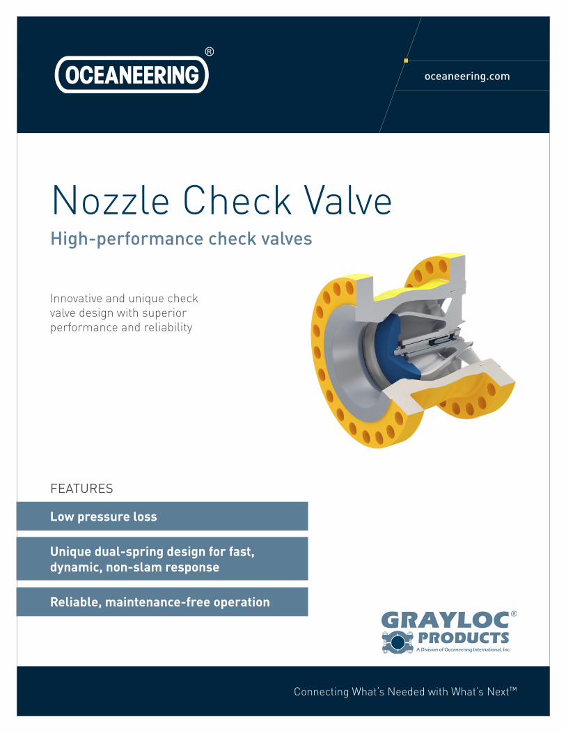
Nozzle Check ValveHigh-performance check valves
FEATURES
Low pressure loss
Unique dual-spring design for fast, dynamic, non-slam response
Reliable, maintenance-free operation
Innovative and unique check valve design with superior performance and reliability
oceaneering.com
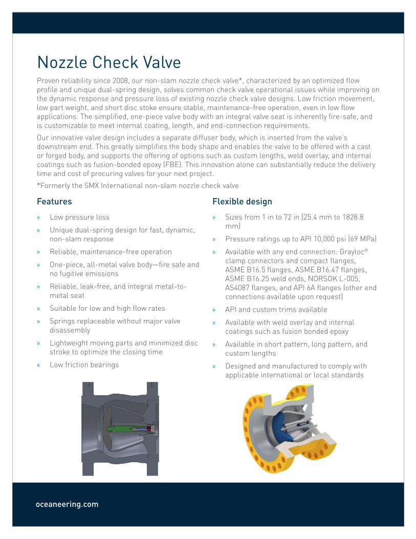
Nozzle Check ValveProven reliability since 2008, our non-slam nozzle check valve*, characterized by an optimized flow profile and unique dual-spring design, solves common check valve operational issues while improving on the dynamic response and pressure loss of existing nozzle check valve designs. Low friction movement, low part weight, and short disc stoke ensure stable, maintenance-free operation, even in low flow applications. The simplified, one-piece valve body with an integral valve seat is inherently fire-safe, and is customizable to meet internal coating, length, and end-connection requirements.
Our innovative valve design includes a separate diffuser body, which is inserted from the valve’s downstream end. This greatly simplifies the body shape and enables the valve to be offered with a cast or forged body, and supports the offering of options such as custom lengths, weld overlay, and internal coatings such as fusion-bonded epoxy (FBE). This innovation alone can substantially reduce the delivery time and cost of procuring valves for your next project.
*Formerly the SMX International non-slam nozzle check valve
Features
» Low pressure loss
» Unique dual-spring design for fast, dynamic, non-slam response
» Reliable, maintenance-free operation
» One-piece, all-metal valve body—fire safe and no fugitive emissions
» Reliable, leak-free, and integral metal-to-metal seat
» Suitable for low and high flow rates
» Springs replaceable without major valve disassembly
» Lightweight moving parts and minimized disc stroke to optimize the closing time
» Low friction bearings
Flexible design
» Sizes from 1 in to 72 in (25.4 mm to 1828.8 mm)
» Pressure ratings up to API 10,000 psi (69 MPa)
» Available with any end connection: Grayloc® clamp connectors and compact flanges, ASME B16.5 flanges, ASME B16.47 flanges, ASME B16.25 weld ends, NORSOK L-005, AS4087 flanges, and API 6A flanges (other end connections available upon request)
» API and custom trims available
» Available with weld overlay and internal coatings such as fusion bonded epoxy
» Available in short pattern, long pattern, and custom lengths
» Designed and manufactured to comply with applicable international or local standards
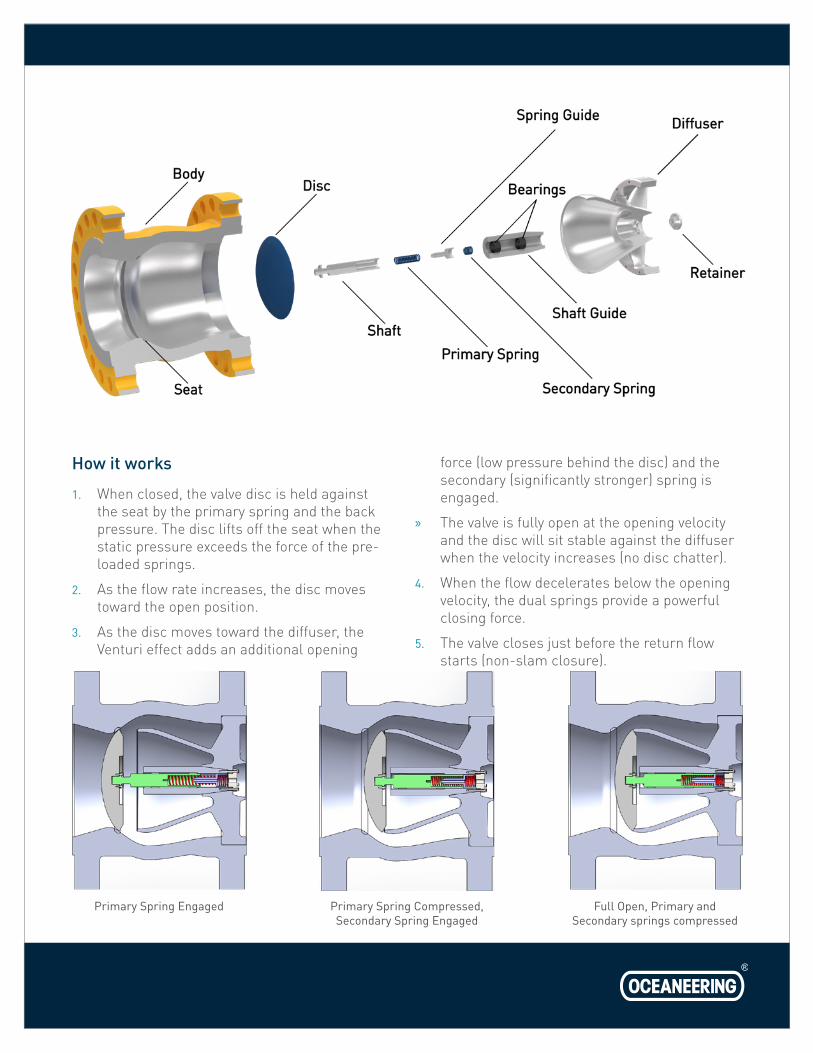
How it works
1. When closed, the valve disc is held against the seat by the primary spring and the back pressure. The disc lifts off the seat when the static pressure exceeds the force of the pre-loaded springs.
2. As the flow rate increases, the disc moves toward the open position.
3. As the disc moves toward the diffuser, the Venturi effect adds an additional opening
force (low pressure behind the disc) and the secondary (significantly stronger) spring is engaged.
» The valve is fully open at the opening velocity and the disc will sit stable against the diffuser when the velocity increases (no disc chatter).
4. When the flow decelerates below the opening velocity, the dual springs provide a powerful closing force.
5. The valve closes just before the return flow starts (non-slam closure).
Primary Spring Engaged Primary Spring Compressed, Secondary Spring Engaged
Full Open, Primary and Secondary springs compressed
oceaneering.com
3210
0
2
4
6
8
0.76bar
1.1bar
0.87s
Pres
sure
(bar
)
Time (s)
105 6 70101
0.1
1
10
Reynolds No.
Loss
Coe
ffici
ent (
k)
Split Disc
Counterbalanced Swing
Disc
PlateSwing
SMX
Ring
3210
0
2
4
6
8
10
12
14
1.4bar
1.5bar
1.53s
7.33bar
Time (s)
Pres
sure
(bar
)
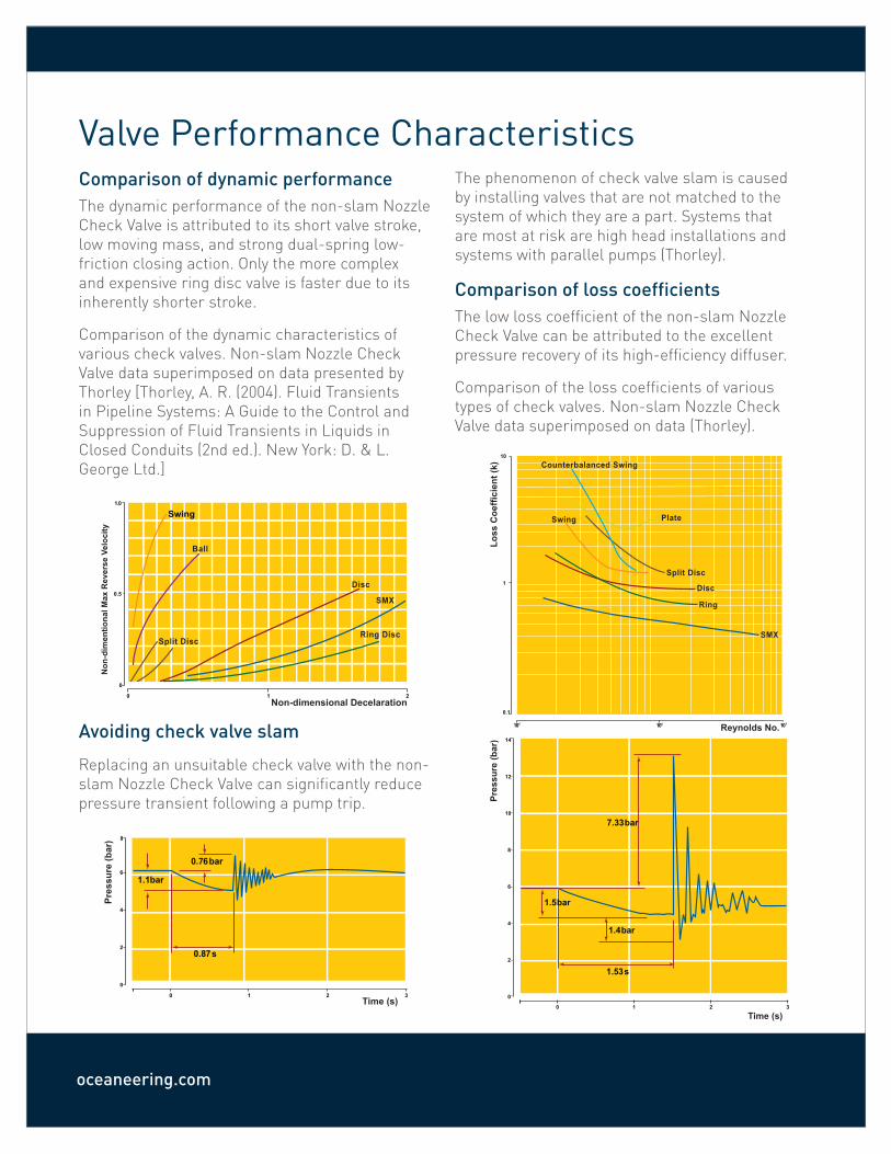
Valve Performance CharacteristicsComparison of dynamic performanceThe dynamic performance of the non-slam Nozzle Check Valve is attributed to its short valve stroke, low moving mass, and strong dual-spring low-friction closing action. Only the more complex and expensive ring disc valve is faster due to its inherently shorter stroke.
Comparison of the dynamic characteristics of various check valves. Non-slam Nozzle Check Valve data superimposed on data presented by Thorley [Thorley, A. R. (2004). Fluid Transients in Pipeline Systems: A Guide to the Control and Suppression of Fluid Transients in Liquids in Closed Conduits (2nd ed.). New York: D. & L. George Ltd.]
Avoiding check valve slam
Replacing an unsuitable check valve with the non-slam Nozzle Check Valve can significantly reduce pressure transient following a pump trip.
The phenomenon of check valve slam is caused by installing valves that are not matched to the system of which they are a part. Systems that are most at risk are high head installations and systems with parallel pumps (Thorley).
Comparison of loss coefficientsThe low loss coefficient of the non-slam Nozzle Check Valve can be attributed to the excellent pressure recovery of its high-efficiency diffuser.
Comparison of the loss coefficients of various types of check valves. Non-slam Nozzle Check Valve data superimposed on data (Thorley).
0
0
0.5
1.0
21
Swing
Non-dimensional Decelaration
Non
-dim
entio
nal M
ax R
ever
se V
eloc
ity
Ball
Split DiscRing Disc
Disc
SMX
Valve SizingThe prime operating function of a check valve is to close quickly at flow reversals to prevent damage to upstream piping and piping components. While performing this function, the valve should have minimum pressure loss during normal operation.
We use valve sizing calculations based on theoretic fluid dynamic considerations that are validated by testing. The valve springs are sized to result in a stable opening and quick closing valve under normal flow conditions.
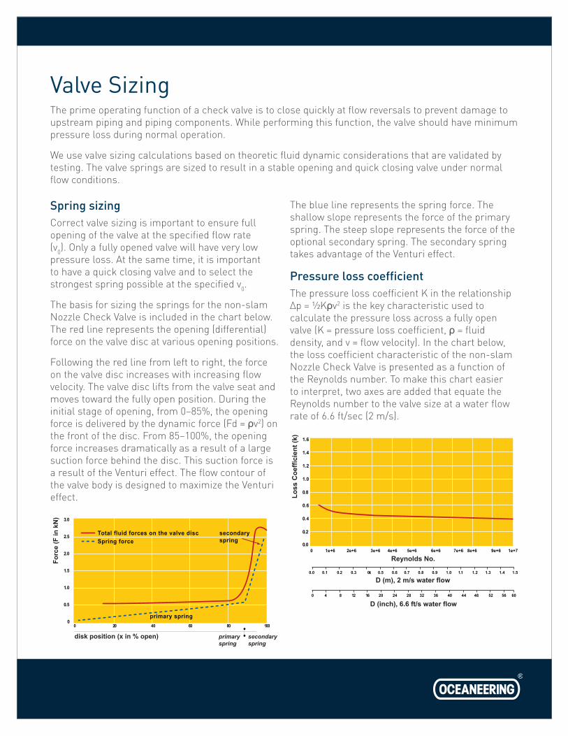
Spring sizingCorrect valve sizing is important to ensure full opening of the valve at the specified flow rate (v0). Only a fully opened valve will have very low pressure loss. At the same time, it is important to have a quick closing valve and to select the strongest spring possible at the specified v0.
The basis for sizing the springs for the non-slam Nozzle Check Valve is included in the chart below. The red line represents the opening (differential) force on the valve disc at various opening positions.
Following the red line from left to right, the force on the valve disc increases with increasing flow velocity. The valve disc lifts from the valve seat and moves toward the fully open position. During the initial stage of opening, from 0–85%, the opening force is delivered by the dynamic force (Fd = ρv2) on the front of the disc. From 85–100%, the opening force increases dramatically as a result of a large suction force behind the disc. This suction force is a result of the Venturi effect. The flow contour of the valve body is designed to maximize the Venturi effect.
The blue line represents the spring force. The shallow slope represents the force of the primary spring. The steep slope represents the force of the optional secondary spring. The secondary spring takes advantage of the Venturi effect.
Pressure loss coefficientThe pressure loss coefficient K in the relationship Δp = ½Kρv2 is the key characteristic used to calculate the pressure loss across a fully open valve (K = pressure loss coefficient, ρ = fluid density, and v = flow velocity). In the chart below, the loss coefficient characteristic of the non-slam Nozzle Check Valve is presented as a function of the Reynolds number. To make this chart easier to interpret, two axes are added that equate the Reynolds number to the valve size at a water flow rate of 6.6 ft/sec (2 m/s).
0 20 40 60 80 100
Total fluid forces on the valve disc
3.0
2.5
2.0
1.5
1.0
0.5
0
Forc
e (F
in k
N)
disk position (x in % open) primaryspring
primary spring
Spring force
secondaryspring
secondaryspring
0 1e+6 2e+6 3e+6 4e+6 5e+6 6e+6 7e+6 8e+6 9e+6 1e+7
0.0 0.1 0.2 0.3 0.4 0.5 0.6 0.7 0.8 0.9 1.0 1.1 1.2 1.3 1.4 1.5
0 4 8 12 16 20 24 28 32 36 40 44 48 52 56 60
1.6
1.4
1.2
1.0
0.8
0.6
0.4
0.2
0.0
Loss
Coe
ffici
ent (
k)
Reynolds No.
D (m), 2 m/s water flow
D (inch), 6.6 ft/s water flow
oceaneering.com
0 2 4 6 8 10 12 14 16
(vo
2.5
2.0
1.5
1.0
0.5
0
pres
sure
loss
(Dp
in k
Pa)
valve opening valve 100% open fluid velocity (v in m/s)
valveOpening
valve 100% open
in m/s)
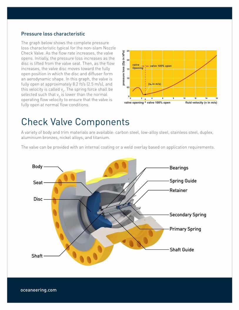
Pressure loss characteristic
The graph below shows the complete pressure loss characteristic typical for the non-slam Nozzle Check Valve. As the flow rate increases, the valve opens. Initially, the pressure loss increases as the disc is lifted from the valve seat. Then, as the flow increases, the valve disc moves toward the fully open position in which the disc and diffuser form an aerodynamic shape. In this graph, the valve is fully open at approximately 8.2 ft/s (2.5 m/s), and this velocity is called v0. The spring force shall be selected such that v0 is lower than the normal operating flow velocity to ensure that the valve is fully open at normal flow conditions.
Check Valve ComponentsA variety of body and trim materials are available: carbon steel, low-alloy steel, stainless steel, duplex, aluminium bronzes, nickel alloys, and titanium.
The valve can be provided with an internal coating or a weld overlay based on application requirements.
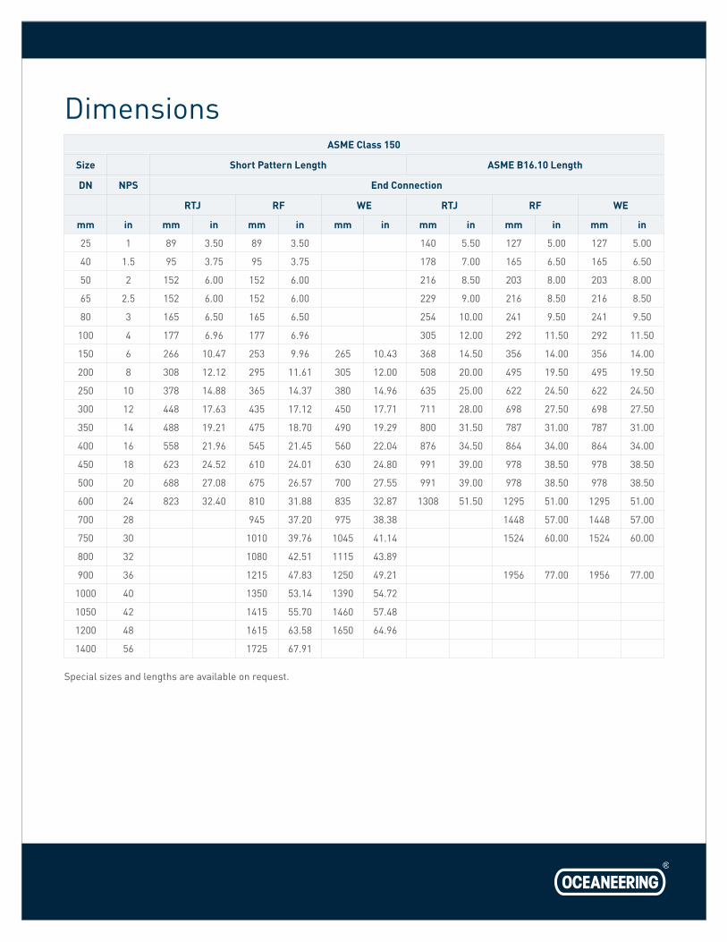
DimensionsASME Class 150
Size Short Pattern Length ASME B16.10 Length
DN NPS End Connection
RTJ RF WE RTJ RF WE
mm in mm in mm in mm in mm in mm in mm in
25 1 89 3.50 89 3.50 140 5.50 127 5.00 127 5.00
40 1.5 95 3.75 95 3.75 178 7.00 165 6.50 165 6.50
50 2 152 6.00 152 6.00 216 8.50 203 8.00 203 8.00
65 2.5 152 6.00 152 6.00 229 9.00 216 8.50 216 8.50
80 3 165 6.50 165 6.50 254 10.00 241 9.50 241 9.50
100 4 177 6.96 177 6.96 305 12.00 292 11.50 292 11.50
150 6 266 10.47 253 9.96 265 10.43 368 14.50 356 14.00 356 14.00
200 8 308 12.12 295 11.61 305 12.00 508 20.00 495 19.50 495 19.50
250 10 378 14.88 365 14.37 380 14.96 635 25.00 622 24.50 622 24.50
300 12 448 17.63 435 17.12 450 17.71 711 28.00 698 27.50 698 27.50
350 14 488 19.21 475 18.70 490 19.29 800 31.50 787 31.00 787 31.00
400 16 558 21.96 545 21.45 560 22.04 876 34.50 864 34.00 864 34.00
450 18 623 24.52 610 24.01 630 24.80 991 39.00 978 38.50 978 38.50
500 20 688 27.08 675 26.57 700 27.55 991 39.00 978 38.50 978 38.50
600 24 823 32.40 810 31.88 835 32.87 1308 51.50 1295 51.00 1295 51.00
700 28 945 37.20 975 38.38 1448 57.00 1448 57.00
750 30 1010 39.76 1045 41.14 1524 60.00 1524 60.00
800 32 1080 42.51 1115 43.89
900 36 1215 47.83 1250 49.21 1956 77.00 1956 77.00
1000 40 1350 53.14 1390 54.72
1050 42 1415 55.70 1460 57.48
1200 48 1615 63.58 1650 64.96
1400 56 1725 67.91
Special sizes and lengths are available on request.
oceaneering.com
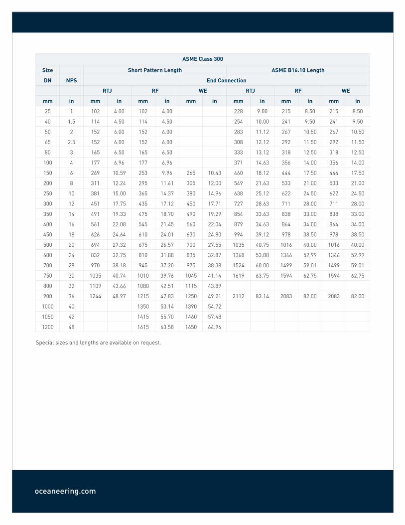
ASME Class 300
Size Short Pattern Length ASME B16.10 Length
DN NPS End Connection
RTJ RF WE RTJ RF WE
mm in mm in mm in mm in mm in mm in mm in
25 1 102 4.00 102 4.00 228 9.00 215 8.50 215 8.50
40 1.5 114 4.50 114 4.50 254 10.00 241 9.50 241 9.50
50 2 152 6.00 152 6.00 283 11.12 267 10.50 267 10.50
65 2.5 152 6.00 152 6.00 308 12.12 292 11.50 292 11.50
80 3 165 6.50 165 6.50 333 13.12 318 12.50 318 12.50
100 4 177 6.96 177 6.96 371 14.63 356 14.00 356 14.00
150 6 269 10.59 253 9.96 265 10.43 460 18.12 444 17.50 444 17.50
200 8 311 12.24 295 11.61 305 12.00 549 21.63 533 21.00 533 21.00
250 10 381 15.00 365 14.37 380 14.96 638 25.12 622 24.50 622 24.50
300 12 451 17.75 435 17.12 450 17.71 727 28.63 711 28.00 711 28.00
350 14 491 19.33 475 18.70 490 19.29 854 33.63 838 33.00 838 33.00
400 16 561 22.08 545 21.45 560 22.04 879 34.63 864 34.00 864 34.00
450 18 626 24.64 610 24.01 630 24.80 994 39.12 978 38.50 978 38.50
500 20 694 27.32 675 26.57 700 27.55 1035 40.75 1016 40.00 1016 40.00
600 24 832 32.75 810 31.88 835 32.87 1368 53.88 1346 52.99 1346 52.99
700 28 970 38.18 945 37.20 975 38.38 1524 60.00 1499 59.01 1499 59.01
750 30 1035 40.74 1010 39.76 1045 41.14 1619 63.75 1594 62.75 1594 62.75
800 32 1109 43.66 1080 42.51 1115 43.89
900 36 1244 48.97 1215 47.83 1250 49.21 2112 83.14 2083 82.00 2083 82.00
1000 40 1350 53.14 1390 54.72
1050 42 1415 55.70 1460 57.48
1200 48 1615 63.58 1650 64.96
Special sizes and lengths are available on request.
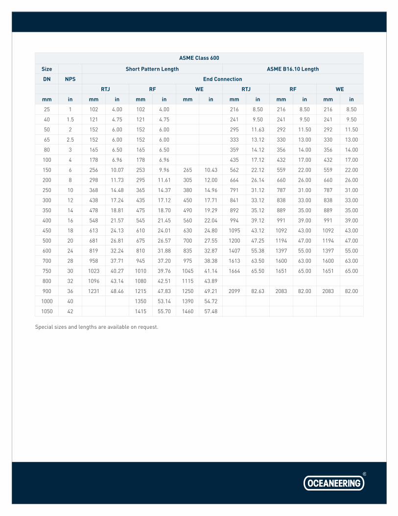
ASME Class 600
Size Short Pattern Length ASME B16.10 Length
DN NPS End Connection
RTJ RF WE RTJ RF WE
mm in mm in mm in mm in mm in mm in mm in
25 1 102 4.00 102 4.00 216 8.50 216 8.50 216 8.50
40 1.5 121 4.75 121 4.75 241 9.50 241 9.50 241 9.50
50 2 152 6.00 152 6.00 295 11.63 292 11.50 292 11.50
65 2.5 152 6.00 152 6.00 333 13.12 330 13.00 330 13.00
80 3 165 6.50 165 6.50 359 14.12 356 14.00 356 14.00
100 4 178 6.96 178 6.96 435 17.12 432 17.00 432 17.00
150 6 256 10.07 253 9.96 265 10.43 562 22.12 559 22.00 559 22.00
200 8 298 11.73 295 11.61 305 12.00 664 26.14 660 26.00 660 26.00
250 10 368 14.48 365 14.37 380 14.96 791 31.12 787 31.00 787 31.00
300 12 438 17.24 435 17.12 450 17.71 841 33.12 838 33.00 838 33.00
350 14 478 18.81 475 18.70 490 19.29 892 35.12 889 35.00 889 35.00
400 16 548 21.57 545 21.45 560 22.04 994 39.12 991 39.00 991 39.00
450 18 613 24.13 610 24.01 630 24.80 1095 43.12 1092 43.00 1092 43.00
500 20 681 26.81 675 26.57 700 27.55 1200 47.25 1194 47.00 1194 47.00
600 24 819 32.24 810 31.88 835 32.87 1407 55.38 1397 55.00 1397 55.00
700 28 958 37.71 945 37.20 975 38.38 1613 63.50 1600 63.00 1600 63.00
750 30 1023 40.27 1010 39.76 1045 41.14 1664 65.50 1651 65.00 1651 65.00
800 32 1096 43.14 1080 42.51 1115 43.89
900 36 1231 48.46 1215 47.83 1250 49.21 2099 82.63 2083 82.00 2083 82.00
1000 40 1350 53.14 1390 54.72
1050 42 1415 55.70 1460 57.48
Special sizes and lengths are available on request.
oceaneering.com
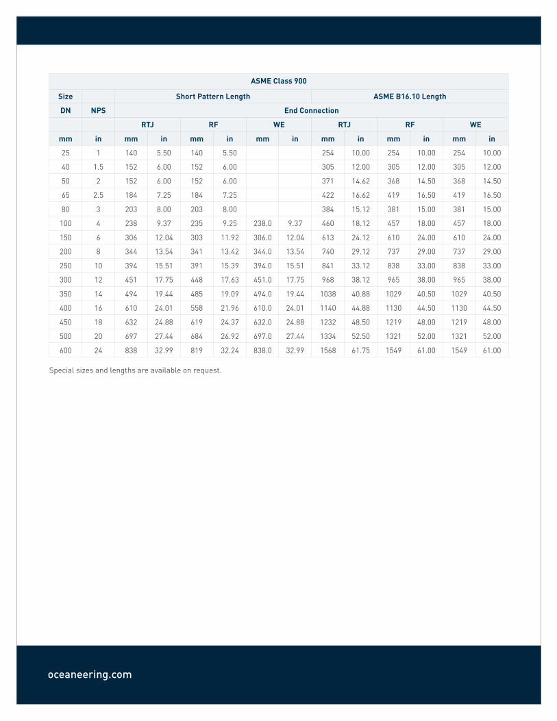
ASME Class 900
Size Short Pattern Length ASME B16.10 Length
DN NPS End Connection
RTJ RF WE RTJ RF WE
mm in mm in mm in mm in mm in mm in mm in
25 1 140 5.50 140 5.50 254 10.00 254 10.00 254 10.00
40 1.5 152 6.00 152 6.00 305 12.00 305 12.00 305 12.00
50 2 152 6.00 152 6.00 371 14.62 368 14.50 368 14.50
65 2.5 184 7.25 184 7.25 422 16.62 419 16.50 419 16.50
80 3 203 8.00 203 8.00 384 15.12 381 15.00 381 15.00
100 4 238 9.37 235 9.25 238.0 9.37 460 18.12 457 18.00 457 18.00
150 6 306 12.04 303 11.92 306.0 12.04 613 24.12 610 24.00 610 24.00
200 8 344 13.54 341 13.42 344.0 13.54 740 29.12 737 29.00 737 29.00
250 10 394 15.51 391 15.39 394.0 15.51 841 33.12 838 33.00 838 33.00
300 12 451 17.75 448 17.63 451.0 17.75 968 38.12 965 38.00 965 38.00
350 14 494 19.44 485 19.09 494.0 19.44 1038 40.88 1029 40.50 1029 40.50
400 16 610 24.01 558 21.96 610.0 24.01 1140 44.88 1130 44.50 1130 44.50
450 18 632 24.88 619 24.37 632.0 24.88 1232 48.50 1219 48.00 1219 48.00
500 20 697 27.44 684 26.92 697.0 27.44 1334 52.50 1321 52.00 1321 52.00
600 24 838 32.99 819 32.24 838.0 32.99 1568 61.75 1549 61.00 1549 61.00
Special sizes and lengths are available on request.
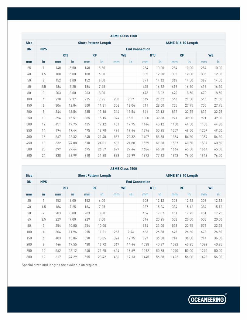
ASME Class 1500
Size Short Pattern Length ASME B16.10 Length
DN NPS End Connection
RTJ RF WE RTJ RF WE
mm in mm in mm in mm in mm in mm in mm in
25 1 140 5.50 140 5.50 254 10.00 254 10.00 254 10.00
40 1.5 180 6.00 180 6.00 305 12.00 305 12.00 305 12.00
50 2 152 6.00 152 6.00 371 14.62 368 14.50 368 14.50
65 2.5 184 7.25 184 7.25 425 16.62 419 16.50 419 16.50
80 3 203 8.00 203 8.00 473 18.62 470 18.50 470 18.50
100 4 238 9.37 235 9.25 238 9.37 549 21.62 546 21.50 546 21.50
150 6 306 12.04 300 11.81 306 12.04 711 28.00 705 27.75 705 27.75
200 8 344 13.54 335 13.18 344 13.54 841 33.13 832 32.75 832 32.75
250 10 394 15.51 385 15.15 394 15.51 1000 39.38 991 39.00 991 39.00
300 12 451 17.75 435 17.12 451 17.75 1146 45.12 1130 44.50 1130 44.50
350 14 494 19.44 475 18.70 494 19.44 1276 50.25 1257 49.50 1257 49.50
400 16 567 22.32 545 21.45 567 22.32 1407 55.38 1384 54.50 1384 54.50
450 18 632 24.88 610 24.01 632 24.88 1559 61.38 1537 60.50 1537 60.50
500 20 697 27.44 675 26.57 697 27.44 1686 66.38 1664 65.50 1664 65.50
600 24 838 32.99 810 31.88 838 32.99 1972 77.62 1943 76.50 1943 76.50
ASME Class 2500
Size Short Pattern Length ASME B16.10 Length
DN NPS End Connection
RTJ RF WE RTJ RF WE
mm in mm in mm in mm in mm in mm in mm in
25 1 152 6.00 152 6.00 308 12.12 308 12.12 308 12.12
40 1.5 184 7.25 184 7.25 387 15.24 384 15.12 384 15.12
50 2 203 8.00 203 8.00 454 17.87 451 17.75 451 17.75
65 2.5 229 9.00 229 9.00 514 20.25 508 20.00 508 20.00
80 3 254 10.00 254 10.00 584 23.00 578 22.75 578 22.75
100 4 304 11.96 295 11.61 253 9.96 683 26.88 673 26.50 673 26.50
150 6 403 15.86 390 15.35 324 12.75 927 36.50 914 36.00 914 36.00
200 8 446 17.55 430 16.92 367 14.44 1038 40.87 1022 40.25 1022 40.25
250 10 562 22.12 540 21.25 424 16.69 1292 50.88 1270 50.00 1270 50.00
300 12 617 24.29 595 23.42 486 19.13 1445 56.88 1422 56.00 1422 56.00
Special sizes and lengths are available on request.

oceaneering.com
© 2019 Oceaneering International, Inc. All rights reserved.
03.0
1.20
19
Grayloc® Products9342 Telge RoadHouston, Texas77095U.S.A. Telephone: +1 713.466.8853Fax: +1 713.937.2335
Grayloc® Products Canada Ltd.1129 Northside Road, Unit 1Burlington, OntarioL7M 1H5CanadaTelephone: +1 905.842.3150Fax: +1 905.842.1785
Grayloc® ProductsSite 39 Silverburn Place, Bridge of Don Industrial EstateAberdeen, ScotlandAB23 8EGTelephone: +44 1224.222790Fax: +44 1224.222780
Oceaneering Grayloc® Connection Systems Sdn. Bhd.Unit 2, Jalan Sungai Kayu Ara 32/31Berjaya Industrial ParkSection 3240460 Shah AlamSelangor Darul EhsanMalaysiaTelephone: +60 3.5870.1200
Related Documents