VM 538 GB/05.06 – Ident-No. 795 213 1 Norm-Centrifugal Pumps PN 10 Series NT Pump dimensions acc. to DIN EN 733 with additional sizes Technical requirements acc. to DIN ISO 9905 Application For pumping pure water, industrial water, sea water, conden- sate, oils, brines, lyes, hot water. The liquids to be pumped must not contain any abrasive particles nor chemically attack the pump materials. Main fields of application In cooling and heating circuits in circulating, water supply, water treatment, irrigation, desalinization, dedusting and spray painting installations as well as in air-conditioning, refrigera- ting, swimming pool and industrial engineering. Design and series construction Horizontal volute casing centrifugal pump with axial inlet, single-flow, single or two-stage, in process design. Series construction according to the modular system. Shaft bearing in a bearing housing which can be optionally provided with a support foot. With bearing housing size 585 and 700 the foot belongs to serial equipment, with bearing housing size 228 it is generally not available. Stable mounting with feet cast on volute casing. The additional two-stage pump sizes correspond in their outer dimensions to the respective single-stage sizes. Due to the two-stage design good efficiencies and low NPSH values are achieved at high delivery heads. Capacity With the sizes according to DIN EN 733, the pump capacity exceeds the required rated power considerably. By additional sizes, the performance range acc. to DIN EN is increased. Performance data Flow Q up to 2300 m 3 /h Delivery head H up to 145 m Temperature of the liquid pumped t up to 140 °C Inlet pressure p s Outlet pressure p d up to 16 bar Inlet pressure plus maximum delivery head must not exceed the outlet pressure. Branch positions and flanges Suction branch: axial Delivery branch: radially upwards Flanges: up to DN 150 acc. to EN 1092-2 PN 16 DN 200 and above acc. to EN 1092-2 PN 10 Shaft coupling and safety guarding Safety guarding according to DIN EN 294 is supplied as soon as the scope of supply includes pump, base plate and shaft cou- pling (acc. to DIN 740 with or without spacer element). The safety standards acc. to DIN EN 809 are met. Shaft sealing By maintenance-free standard mechanical seal in unbalanced design in different materials (see page 2) or by gland packing. Bearing and lubrication By two groove ball bearings acc. to DIN 625, grease-lubricated for the whole service life, bearing clearance C3. Dismantling of the insert unit When using the spacer coupling the insert unit can because of the process design be dismantled towards the motor side, whereas the volute casing and the motor may remain on the base plate and the pipes on the volute casing. Combination of structural components The table on page 3 shows the combination possibilities of structural components of all NT sizes. The modular system allows reduced stockkeeping of spare parts. Explosion protection The pump fulfils the requirements according to EC Explosion Protection Directive 94/9/EG (ATEX 100a) for equipment of equipment group II, category 2 G. Categorisation into temperature classes according to EN 13 463-1 depends on the temperature of the pumped liq- uid. The max. permissible temperature of the pumped liquid for the respective temperature classes are shown in the spe- cific order data sheet. Note: In case of the operation of a category 2 pump, the un- acceptable heating of the pump surfaces caused by a possible operational fault must be prevented by a control mechanism. Drive Standard: surface-cooled, three-phase squirrel-cage motors, IM B3 type of construction, degree of protection IP 55 accord- ing to IEC standard, class F insulation. Performances and main dimensions according to DIN 42 673. Further drive options are possible. Connections The following connections are provided: FD Draining FF Filling LO Leakage outlet PM2 Pressure gauge Connection FF not provided in sizes 20-160/01, 25-200/01 und 2/25- 200/01. Refilling possible at connection PM2. Base plates Standard: channel steel base plate. Optionally: massive base plate of cast iron (dimensions acc. to DIN 24 259) with a drip channel for leakage. Installation dimensions are available in ALLWEILER drawing archive ALL2CAD.

Welcome message from author
This document is posted to help you gain knowledge. Please leave a comment to let me know what you think about it! Share it to your friends and learn new things together.
Transcript

VM 538 GB/05.06 – Ident-No. 795 213 1
Norm-Centrifugal Pumps PN 10 Series NT
Pump dimensions acc. to DIN EN 733 with additional sizes Technical requirements acc. to DIN ISO 9905
Application For pumping pure water, industrial water, sea water, conden-sate, oils, brines, lyes, hot water. The liquids to be pumped must not contain any abrasive particles nor chemically attack the pump materials.
Main fields of application In cooling and heating circuits in circulating, water supply, water treatment, irrigation, desalinization, dedusting and spray painting installations as well as in air-conditioning, refrigera- ting, swimming pool and industrial engineering.
Design and series construction Horizontal volute casing centrifugal pump with axial inlet, single-flow, single or two-stage, in process design.
Series construction according to the modular system. Shaft bearing in a bearing housing which can be optionally provided with a support foot. With bearing housing size 585 and 700 the foot belongs to serial equipment, with bearing housing size 228 it is generally not available. Stable mounting with feet cast on volute casing.
The additional two-stage pump sizes correspond in their outer dimensions to the respective single-stage sizes. Due to the two-stage design good efficiencies and low NPSH values are achieved at high delivery heads.
Capacity With the sizes according to DIN EN 733, the pump capacity exceeds the required rated power considerably. By additional sizes, the performance range acc. to DIN EN is increased.
Performance data Flow Q up to 2300 m3/h Delivery head H up to 145 m Temperature of the liquid pumped t up to 140 °C Inlet pressure ps Outlet pressure pd up to 16 bar
Inlet pressure plus maximum delivery head must not exceed the outlet pressure.
Branch positions and flanges Suction branch: axial Delivery branch: radially upwards Flanges: up to DN 150 acc. to EN 1092-2 PN 16 DN 200 and above acc. to EN 1092-2 PN 10
Shaft coupling and safety guarding Safety guarding according to DIN EN 294 is supplied as soon as the scope of supply includes pump, base plate and shaft cou-pling (acc. to DIN 740 with or without spacer element). The safety standards acc. to DIN EN 809 are met.
Shaft sealing By maintenance-free standard mechanical seal in unbalanced design in different materials (see page 2) or by gland packing.
Bearing and lubrication By two groove ball bearings acc. to DIN 625, grease-lubricated for the whole service life, bearing clearance C3.
Dismantling of the insert unit When using the spacer coupling the insert unit can because of the process design be dismantled towards the motor side, whereas the volute casing and the motor may remain on the base plate and the pipes on the volute casing.
Combination of structural components The table on page 3 shows the combination possibilities of structural components of all NT sizes. The modular system allows reduced stockkeeping of spare parts.
Explosion protection The pump fulfils the requirements according to EC Explosion Protection Directive 94/9/EG (ATEX 100a) for equipment of equipment group II, category 2 G.
Categorisation into temperature classes according to EN 13 463-1 depends on the temperature of the pumped liq-uid. The max. permissible temperature of the pumped liquid for the respective temperature classes are shown in the spe-cific order data sheet. Note: In case of the operation of a category 2 pump, the un-acceptable heating of the pump surfaces caused by a possible operational fault must be prevented by a control mechanism.
Drive Standard: surface-cooled, three-phase squirrel-cage motors, IM B3 type of construction, degree of protection IP 55 accord-ing to IEC standard, class F insulation. Performances and main dimensions according to DIN 42 673. Further drive options are possible.
Connections The following connections are provided:
FD Draining FF Filling LO Leakage outlet PM2 Pressure gauge
Connection FF not provided in sizes 20-160/01, 25-200/01 und 2/25-200/01. Refilling possible at connection PM2.
Base plates Standard: channel steel base plate. Optionally: massive base plate of cast iron (dimensions acc. to DIN 24 259) with a drip channel for leakage. Installation dimensions are available in ALLWEILER drawing archive ALL2CAD.
Series NT
VM 538 GB/05.06 – Ident-No. 795 213 2
With the two-stage additional pump sizes, the number of stages is placed with a slash in front of the delivery branch nominal width, e.g. NT 2/32-200/01...
This abbreviation is entered on the nameplate. With the two-stage additional pump sizes, the actual impeller diameter relates to the second stage.
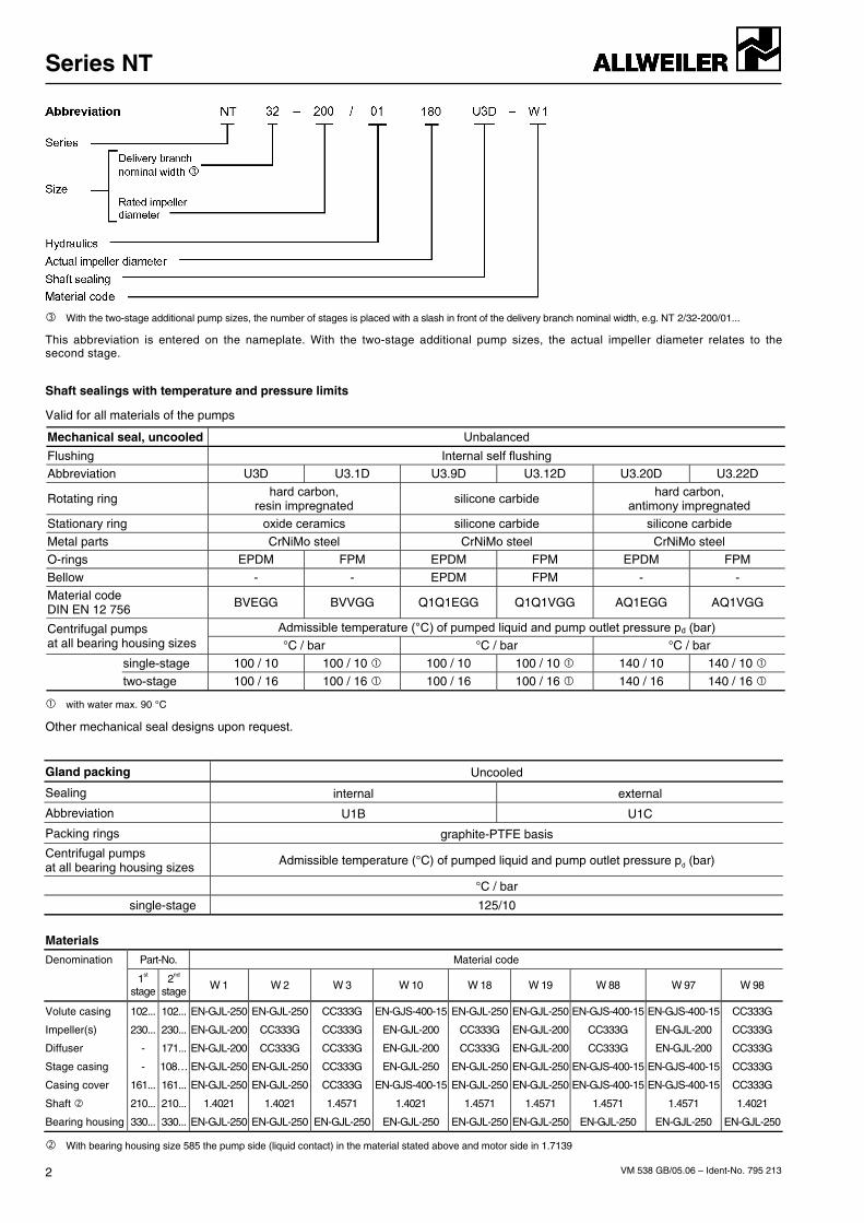
Shaft sealings with temperature and pressure limits
Valid for all materials of the pumps
Mechanical seal, uncooled Unbalanced
Flushing Internal self flushing Abbreviation U3D U3.1D U3.9D U3.12D U3.20D U3.22D
Rotating ring hard carbon, resin impregnated silicone carbide hard carbon,
antimony impregnated Stationary ring oxide ceramics silicone carbide silicone carbide
Metal parts CrNiMo steel CrNiMo steel CrNiMo steel O-rings EPDM FPM EPDM FPM EPDM FPM
Bellow - - EPDM FPM - - Material code DIN EN 12 756 BVEGG BVVGG Q1Q1EGG Q1Q1VGG AQ1EGG AQ1VGG
Admissible temperature (°C) of pumped liquid and pump outlet pressure pd (bar) Centrifugal pumps at all bearing housing sizes °C / bar °C / bar °C / bar single-stage 100 / 10 100 / 10 100 / 10 100 / 10 140 / 10 140 / 10
two-stage 100 / 16 100 / 16 100 / 16 100 / 16 140 / 16 140 / 16
with water max. 90 °C
Other mechanical seal designs upon request.
Gland packing Uncooled
Sealing internal external
Abbreviation U1B U1C
Packing rings graphite-PTFE basis
Centrifugal pumps at all bearing housing sizes Admissible temperature (°C) of pumped liquid and pump outlet pressure pd (bar)
°C / bar
single-stage 125/10
Materials
Part-No. Material code Denomination
1st stage
2nd stage W 1 W 2 W 3 W 10 W 18 W 19 W 88 W 97 W 98
Volute casing 102... 102... EN-GJL-250 EN-GJL-250 CC333G EN-GJS-400-15 EN-GJL-250 EN-GJL-250 EN-GJS-400-15 EN-GJS-400-15 CC333G
Impeller(s) 230... 230... EN-GJL-200 CC333G CC333G EN-GJL-200 CC333G EN-GJL-200 CC333G EN-GJL-200 CC333G
Diffuser - 171... EN-GJL-200 CC333G CC333G EN-GJL-200 CC333G EN-GJL-200 CC333G EN-GJL-200 CC333G
Stage casing - 108… EN-GJL-250 EN-GJL-250 CC333G EN-GJL-250 EN-GJL-250 EN-GJL-250 EN-GJS-400-15 EN-GJS-400-15 CC333G
Casing cover 161... 161... EN-GJL-250 EN-GJL-250 CC333G EN-GJS-400-15 EN-GJL-250 EN-GJL-250 EN-GJS-400-15 EN-GJS-400-15 CC333G
Shaft 210... 210... 1.4021 1.4021 1.4571 1.4021 1.4571 1.4571 1.4571 1.4571 1.4021
Bearing housing 330... 330... EN-GJL-250 EN-GJL-250 EN-GJL-250 EN-GJL-250 EN-GJL-250 EN-GJL-250 EN-GJL-250 EN-GJL-250 EN-GJL-250
With bearing housing size 585 the pump side (liquid contact) in the material stated above and motor side in 1.7139

Series NT
VM 538 GB/05.06 – Ident-No. 795 213 3
Combination of structural components
The table below shows the combination possibilities of structural components and parts of the standard sizes including additional sizes.
Within a vertical column, parts with identical numbers are interchangeable.
The modular system allows a reduced stockkeeping of spare parts.
Pump size Impeller Shaft sealing
acc. to DIN EN 733
Additional size
Bearing housing
size
NT NT
Volute casing
Impeller
1st stage
2nd stage
Diffuser Stagecasing
Intermediatering
Casing cover
Bearing housing
Shaft
Support foot
Mecha-nical seal
Ø
Glandpacking
- 20-160/01 1 228
- 25-160/01 2 1 - - - - - 1 1 1 - 16 16
- 25-200/01 2 - - - - 2 2 30
- 2/25-200/01 3
- 1 1 1 1 3 3 1
-
32-160/01 - 4 3 2
32-200/01 - 4 - - - - 2 2 30
- 2/32-200/01 5
- 1 1 1 1 3 3 1
-
40-160/01 - 6 5 2
40-200/01 - 7 6
-
1
40-250/01 - 7
- - - -
1
2 2 30
- 2/40-250/01 8
- 2 2 2 2 4 3 3
-
50-160/01 - 9 8
50-200/01 - 10 9
- 1
50-250/01 - 10
- - - -
1
2 2 30
- 2/50-250/01 11
- 3 2 2 2 4 3 3
-
65-160/01 - 12 11 -
1
65-200/02 - 13 12 1
80-160/01 - 14 13 3
360
- 100-160/01 15 14
- - - -
-
2
2
2
4
30
30
65-250/01 - 16 15 - 5
65-315/01 - 17 16 2 6
- 65-400/01 18 17 3 7
80-200/02 - 19 18 8
80-250/01 - 20 19 -
5
80-315/01 - 21 20 2 7
100-200/01 - 22 21 5
100-250/01 - 23 22 -
6
100-315/01 - 24 23 2
125-200/01 - 25 24
125-250/01 - 26 25
7
470
150-200/01 - 27 26
- - - -
-
5
3
4
8
40 40
- 80-400/02 28 27
100-400/02 - 29 28
125-315/01 - 30 29
9
125-400/02 - 31 30
6
10
- 150-250/02 32 31 7
150-315/01 - 33 32 9
150-400/02 - 34 33 6
10
530
- 200-250/02 35 34
- - - - -
7
4 5
11
50 50
- 200-315/01 36 35
- 200-400/01 37 36 12
- 250-315/01 38 37
- 250-400/01 39 38
- - - - - 8
13
- 300-315/03 40 39
585
- 300-400/03 41 40 - - - - - 9
5 6
14
65 65
- 300-315/03 40 41 700
- 300-400/03 41 42 - - - - - 9 6 7 14 80 80

Series NT
VM 538 GB/05.06 – Ident-No. 795 213 4
Adaptation to changing operating conditions possible by turning down the impeller.
Optimized hydraulic parts according to DIN EN 733 with very good efficien-cies and NPSH values.
Pressure safe casing parts designed for high reliability of operation.
Negligible axial thrust by fine adaptation of the relief bores.
Flanges according toDIN EN 1092-2 PN 10/16, other flange designs possible.
Connection dimensions and capacities according to DIN EN 733.
Shaft sealing by mechanical seal or gland packing according to the operating conditions.
No offset of the shaftbecause of one-piece bearing housing.
Groove ball bearings rigid and lubricated for the whole service life.
Large selection of ma-terials.
Process design; when dismounting the pump the volute casing remains in the piping.
Two-stage sizes with their outer dimensions correspond to the respec-tive single-stage sizes.
Large delivery heads with two-stage sizes (2/25-200/01, 2/32-200/01, 2/40-250/01, 2/50-250/01). The connection dimensions correspond with the single stage design.
By additional pump sizes performance range according to DIN EN 733 is increased.
Reduced stockkeeping of spare parts due to use of as much non-variable parts as possible (modular system).

Series NT
VM 538 GB/05.06 – Ident-No. 795 213 5
Performance graphs
n = 1450 1/min
n = 2900 1/min
Valid for ρ = 1 kg/dm³ and ν = 1 mm²/s. Exact performance data to be taken from the individual characteristics and the selection programme ALLSELECT.

Series NT
VM 538 GB/05.06 – Ident-No. 795 213 6
n = 1750 1/min
n = 3500 1/min
Valid for ρ = 1 kg/dm³ and ν = 1 mm²/s. Exact performance data to be taken from the individual characteristics and the selection programme ALLSELECT.

Series NT
VM 538 GB/05.06 – Ident-No. 795 213 7
Sectional drawings
Sizes on bearing housing size 228
U3 ... D mechanical seal unbalanced
Sizes on bearing housing size 360
Bearing housing size 360, two-stage, U3 ... D - mechanical seal unbalanced
Casing cover design with sizes 2/40-250 and 2/50-250
Series NT
VM 538 GB/05.06 – Ident-No. 795 213 8
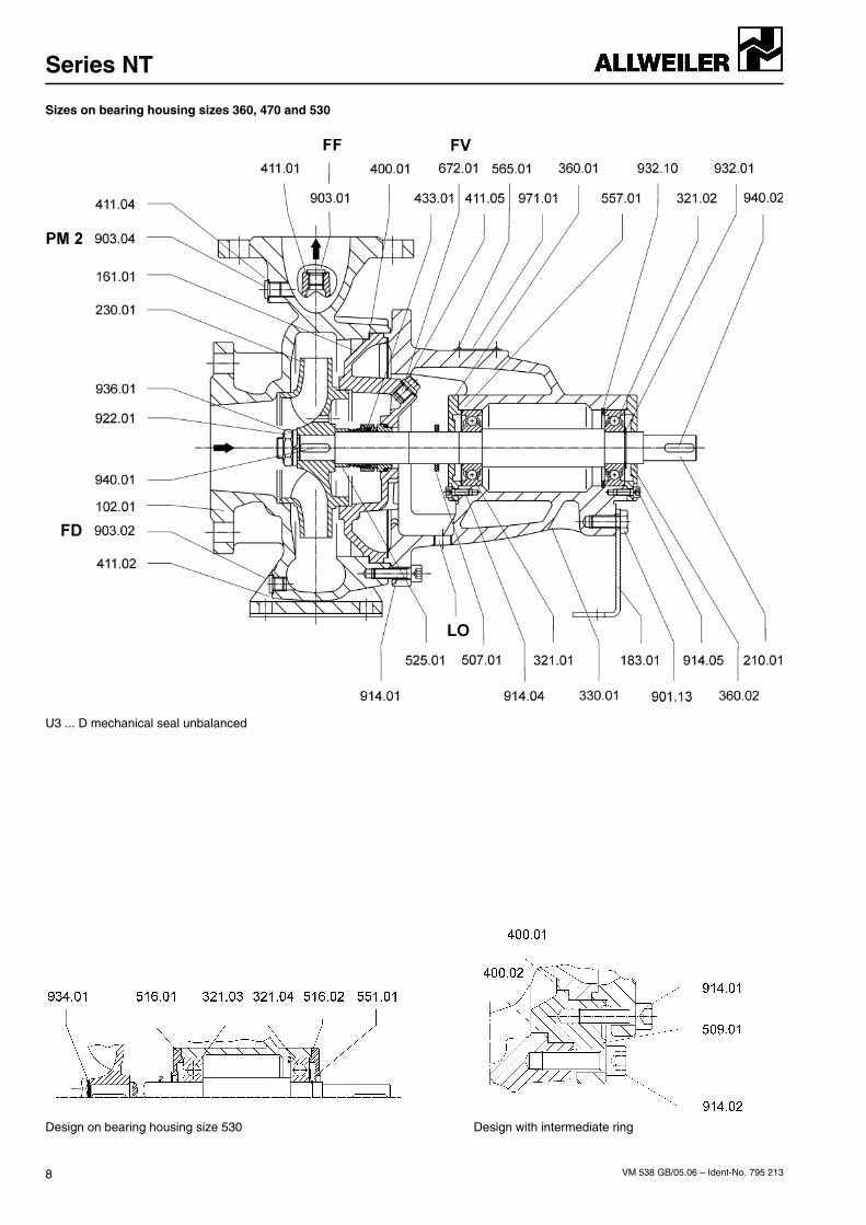
Sizes on bearing housing sizes 360, 470 and 530
U3 ... D mechanical seal unbalanced
Design on bearing housing size 530 Design with intermediate ring

Series NT
VM 538 GB/05.06 – Ident-No. 795 213 9
Sizes on bearing housing size 585
U3 ... D mechanical seal unbalanced
Gland packing with internal sealing U1B Gland packing with external sealing U1C Mechanical seal unbalanced U3.9D, U3.12D

Series NT
VM 538 GB/05.06 – Ident-No. 795 213 10
Sizes 300-315 and 300-400 on bearing housing 585
U3 … D - mechanical seal unbalanced

Series NT
VM 538 GB/05.06 – Ident-No. 795 213 11
Sizes 300-315 and 300-400 on bearing housing 700
U3 … D - mechanical seal unbalanced
Design with wear ring V2 Connection C01 on the volute casing Detail X on the casing cover
Series NT
VM 538 GB/05.06 – Ident-No. 795 213 12
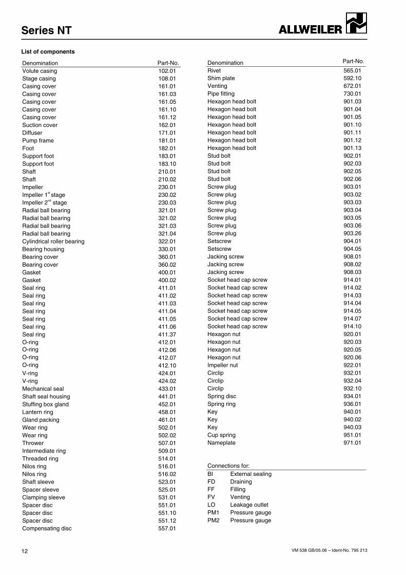
List of components
Denomination Part-No.Volute casing 102.01 Stage casing 108.01 Casing cover 161.01 Casing cover 161.03 Casing cover 161.05 Casing cover 161.10 Casing cover 161.12 Suction cover 162.01 Diffuser 171.01 Pump frame 181.01 Foot 182.01 Support foot 183.01 Support foot 183.10 Shaft 210.01 Shaft 210.02 Impeller 230.01 Impeller 1st stage 230.02 Impeller 2nd stage 230.03 Radial ball bearing 321.01 Radial ball bearing 321.02 Radial ball bearing 321.03 Radial ball bearing 321.04 Cylindrical roller bearing 322.01 Bearing housing 330.01 Bearing cover 360.01 Bearing cover 360.02 Gasket 400.01 Gasket 400.02 Seal ring 411.01 Seal ring 411.02 Seal ring 411.03 Seal ring 411.04 Seal ring 411.05 Seal ring 411.06 Seal ring 411.37 O-ring 412.01 O-ring 412.06 O-ring 412.07 O-ring 412.10 V-ring 424.01 V-ring 424.02 Mechanical seal 433.01 Shaft seal housing 441.01 Stuffing box gland 452.01 Lantern ring 458.01 Gland packing 461.01 Wear ring 502.01 Wear ring 502.02 Thrower 507.01 Intermediate ring 509.01 Threaded ring 514.01 Nilos ring 516.01 Nilos ring 516.02 Shaft sleeve 523.01 Spacer sleeve 525.01 Clamping sleeve 531.01 Spacer disc 551.01 Spacer disc 551.10 Spacer disc 551.12 Compensating disc 557.01
Denomination Part-No.
Rivet 565.01 Shim plate 592.10 Venting 672.01 Pipe fitting 730.01 Hexagon head bolt 901.03 Hexagon head bolt 901.04 Hexagon head bolt 901.05 Hexagon head bolt 901.10 Hexagon head bolt 901.11 Hexagon head bolt 901.12 Hexagon head bolt 901.13 Stud bolt 902.01 Stud bolt 902.03 Stud bolt 902.05 Stud bolt 902.06 Screw plug 903.01 Screw plug 903.02 Screw plug 903.03 Screw plug 903.04 Screw plug 903.05 Screw plug 903.06 Screw plug 903.26 Setscrew 904.01 Setscrew 904.05 Jacking screw 908.01 Jacking screw 908.02 Jacking screw 908.03 Socket head cap screw 914.01 Socket head cap screw 914.02 Socket head cap screw 914.03 Socket head cap screw 914.04 Socket head cap screw 914.05 Socket head cap screw 914.07 Socket head cap screw 914.10 Hexagon nut 920.01 Hexagon nut 920.03 Hexagon nut 920.05 Hexagon nut 920.06 Impeller nut 922.01 Circlip 932.01 Circlip 932.04 Circlip 932.10 Spring disc 934.01 Spring ring 936.01 Key 940.01 Key 940.02 Key 940.03 Cup spring 951.01 Nameplate 971.01 Connections for: BI External sealing FD Draining FF Filling FV Venting LO Leakage outlet PM1 Pressure gauge PM2 Pressure gauge
Series NT
VM 538 GB/05.06 – Ident-No. 795 213 13
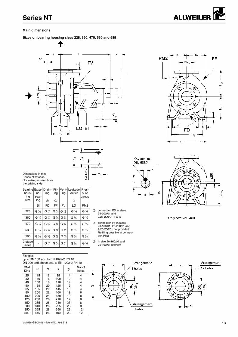
Main dimensions
Sizes on bearing housing sizes 228, 360, 470, 530 and 585
Dimensions in mm. Sense of rotation: clockwise, as seen from the driving side.
Bearing hous-
ing size
Exter- nal
seal- ing
Drain- ing
Fill- ing
Vent- ing
Leakage outlet
Pres- sure
gauge
Bl FD FF FV LO PM2
228 G ⅛ G ¼ G ¼ G ⅛ G ¼ G ¼
360 G ¼ G ¼ G ¼ G ¼ G ⅜ G ¼
connection FD in sizes 25-200/01 and 2/25-200/01 = G ½
470 G ¼ G ⅜ G ⅜ G ⅜ G ⅜ G ⅜
530 G ⅜ G ⅜ G ⅜ G ½ G ⅜ G ⅜
585 G ⅜ G ⅜ G ⅜ G ½ G ⅜ G ⅜
connection FF in sizes 20-160/01, 25-200/01 and 2/25-200/01 not provided. Refilling possible at connec-tion PM2
2-stage sizes - G ¼ G ¼ G ¼ G ⅜ G ¼ in size 20-160/01 and
25-160/01 laterally
Flanges: up to DN 150 acc. to EN 1092-2 PN 16 DN 200 and above acc. to EN 1092-2 PN 10
DNd DNs
D bf k g No. of holes
25 115 16 85 14 432 140 18 100 19 4 40 150 18 110 19 4 50 165 20 125 19 4 65 185 20 145 19 4 80 200 22 160 19 8
100 220 24 180 19 8 125 250 26 210 19 8 150 285 26 240 23 8 200 340 26 295 23 8 250 395 28 350 23 12 300 445 28 400 23 12
Series NT
VM 538 GB/05.06 – Ident-No. 795 213 14
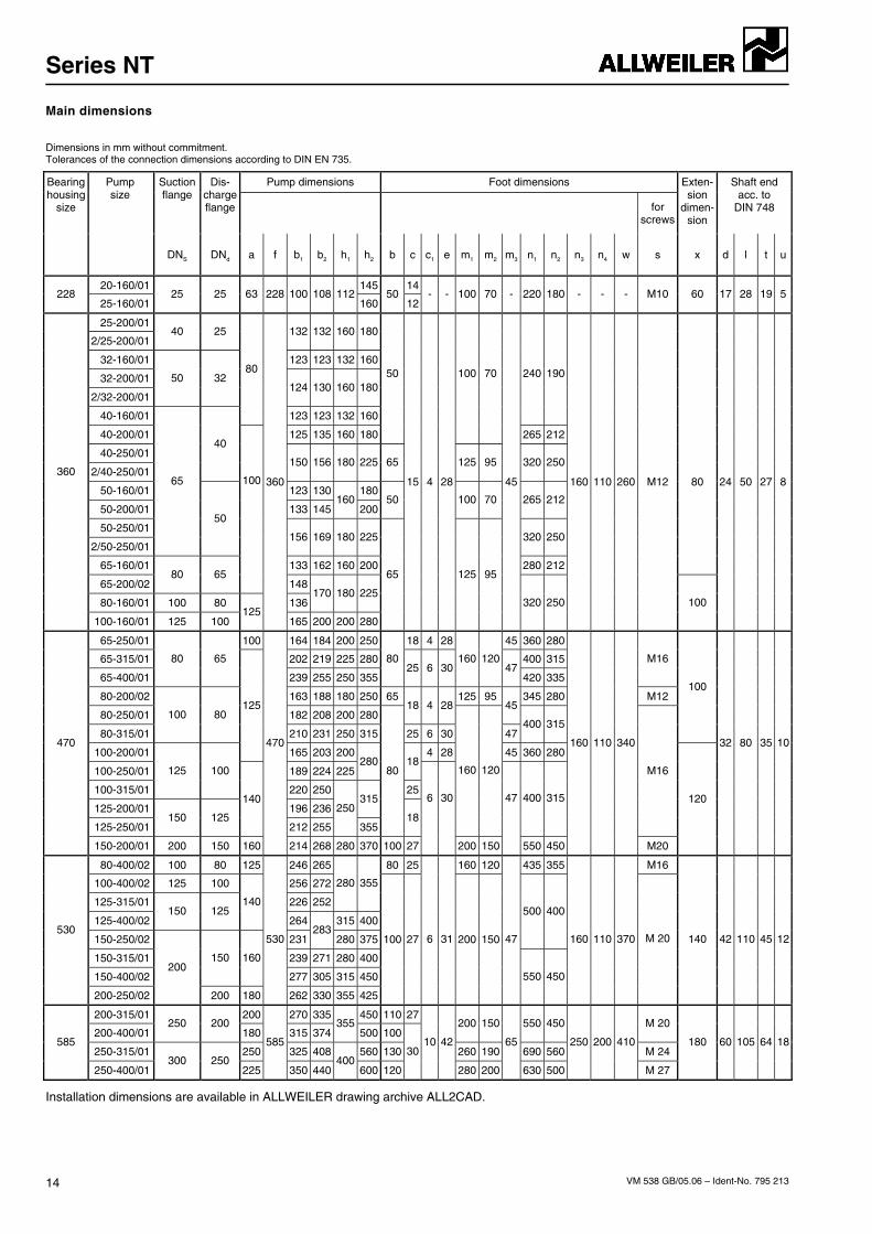
Main dimensions
Dimensions in mm without commitment. Tolerances of the connection dimensions according to DIN EN 735.
Pump dimensions Foot dimensions Suction flange
Dis- charge flange
for
screws
Exten- sion
dimen- sion
Shaft end acc. to
DIN 748
Bearing housing
size
Pump size
DNS DNd a f b1 b2 h1 h2 b c c1 e m1 m2 m3 n1 n2 n3 n4 w s x d l t u
20-160/01 145 14228
25-160/01 25 25 63 228 100 108 112
16050
12- - 100 70 - 220 180 - - - M10 60 17 28 19 5
25-200/01
2/25-200/01 40 25 132 132 160 180
32-160/01 123 123 132 160
32-200/01
2/32-200/01
50 32 124 130 160 180
40-160/01
80
123 123 132 160
240 190
40-200/01 125 135 160 180
50 100 70
265 212
40-250/01
2/40-250/01
40
150 156 180 225 65 125 95 320 250
50-160/01 123 130 180
50-200/01 133 145 160
20050 100 70 265 212
50-250/01
2/50-250/01
65
50
156 169 180 225 320 250
65-160/01 133 162 160 200 280 212
80
65-200/02 80 65
100
148
80-160/01 100 80 136 170 180 225
360
100-160/01 125 100 125
360
165 200 200 280
65
15 4 28
125 95
45
320 250
160 110 260 M12
100
24 50 27 8
65-250/01 100 164 184 200 250 18 4 28 45 360 280
65-315/01 202 219 225 280 400 315
65-400/01
80 65
239 255 250 355
8025 6 30
160 12047
420 335
M16
80-200/02 163 188 180 250 65 125 95 345 280 M12
80-250/01 182 208 200 28018 4 28 45
80-315/01
100 80
210 231 250 315 25 6 30 47400 315
100
100-200/01
125
165 203 200 4 28 45 360 280
100-250/01 189 224 225 280 18
100-315/01
125 100
220 250 25
125-200/01 196 236 315
125-250/01 150 125
140
212 255
250
355
80
18
160 120
400 315
M16
470
150-200/01 200 150 160
470
214 268 280 370 100 27
6 30
200 150
47
550 450
160 110 340
M20
120
32 80 35 10
80-400/02 100 80 125 246 265 80 25 160 120 435 355 M16
100-400/02 125 100 256 272
125-315/01 226 252
280 355
125-400/02 150 125
140
264 315 400
150-250/02 231 283
280 375
500 400
150-315/01 239 271 280 400
150-400/02
150 160
277 305 315 450
530
200-250/02
200
200 180
530
262 330 355 425
100 27 6 31 200 150 47
550 450
160 110 370 M 20 140 42 110 45 12
200-315/01 200 270 335 450 110 27
200-400/01 250 200
180 315 374 355
500 100200 150 550 450 M 20
250-315/01 250 325 408 560 130 260 190 690 560 M 24 585
250-400/01 300 250
225
585
350 440 400
600 120
3010 42
280 200
65
630 500
250 200 410
M 27
180 60 105 64 18
Installation dimensions are available in ALLWEILER drawing archive ALL2CAD.
Series NT
VM 538 GB/05.06 – Ident-No. 795 213 15
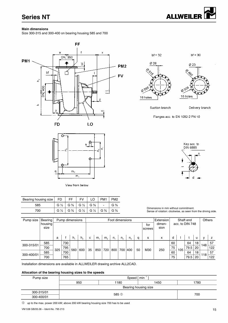
Main dimensions Size 300-315 and 300-400 on bearing housing 585 and 700
Bearing housing size FD FF FV LO PM1 PM2
585 G ½ G ⅜ G ½ G ⅜ - G ⅜
700 G ½ G ⅜ G ½ G ½ G ⅜ G ⅜ Dimensions in mm without commitment. Sense of rotation: clockwise, as seen from the driving side.
Pump dimensions Foot dimensions Extension
dimen-sion
Shaft end acc. to DIN 748
Others Pump size Bearing housing
size for
screws
a f h1 h2 c m1 m2 n1 n2 n3 q s x d l t u y z
585 730 60 64 18 57 300-315/01
700 795 75 79.5 20148
122
585 700 60 64 18 57 300-400/01
700
325
765
560 600 35 850 720 800 700 400 50 M30 250
75
105
79.5 20118
122
Installation dimensions are available in ALLWEILER drawing archive ALL2CAD.
Allocation of the bearing housing sizes to the speeds
Speed [ min -1 ] 950 1180 1450 1780
Pump size
Bearing housing size
300-315/01 300-400/01
585 700
up to the max. power 200 kW; above 200 kW bearing housing size 700 has to be used
Series NT
VM 538 GB/05.06 – Ident-No. 795 213
Subject for technical alterations.
ALLWEILER AG Postfach 1140 78301 Radolfzell Allweilerstr. 1 78315 Radolfzell Germany Tel. +49 (0)7732 86-0 Fax. + 49 (0)7732 86-436 E-mail: [email protected] Internet: http://www.allweiler.com
Related Documents