International Research Journal of Engineering and Technology (IRJET) e-ISSN: 2395 -0056 Volume: 03 Issue: 04 | April-2016 www.irjet.net p-ISSN: 2395-0072 © 2016, IRJET | Impact Factor value: 4.45 | ISO 9001:2008 Certified Journal | Page 2756 Neoteric Sensorless Control of BLDC Motor Drives Meghana.P Dept. of EIE, RNS Institute of Technology, Bangalore,India Mr. Chetan Ghatage, Asst. Prof , Dept. of EIE, RNS Institute of Technology, Bangalore,India ------------------------------------------------------------------------------------------------------------------------- Abstarct—This paper builds up the brushless dc (BLDC) sensorless control framework .The sensorless systems that depend on a hysteresis comparator and a potential start-up technique with a high beginning torque are proposed. The hysteresis comparator is utilized to make up for the stage deferral of the back EMFs because of a low-pass channel (LPF) and likewise keep numerous yield moves from commotion or swell in the terminal voltages. The rotor position is adjusted at stop for greatest beginning torque without an extra sensor and any data of engine parameters. Likewise, the stator current can be effectively balanced by adjusting the beat width of the exchanging gadgets amid arrangement. A few examinations are actualized on a solitary chip DSP controller to exhibit the attainability of the proposed sensorless and start-up strategies. Keywords—Brushless dc (BLDC) engine, hysteresis comparator, sensorless control, start-up procedure. I.INTRODUCTION Lately, the brushless dc (BLDC) engine is getting much enthusiasm for car applications particularly on vehicle fuel pumps because of its high proficiency, minimized size, and lower support when contrasted with a brush dc engine [1], [2]. All together to acquire a precise and swell free immediate torque of the BLDC engine, the rotor position data for stator current replacement must be known, which can be acquired utilizing lobby sensors mounted on a rotor [3], [4]. This outcomes in a high costs and in addition poor unwavering quality, which are not kidding issues at the vehicle applications The zero-intersection of the back EMF measured from the stator winding is distinguished and the replacement focuses can be evaluated by moving 30◦ from the zero intersection of the back EMFs [5]. The execution of the sensorless drive weakens with the stage shifter in the transient state. Additionally, it is touchy to the stage postponement of the low-pass channel (LPF) particularly at the rapid. Most sensorless procedures depend on back EMF estimation. In any case, when an engine is at stop or low speed, it is surely understood that the back EMF is too little to evaluate an exact rotor position. Along these lines, a particular start-up procedure in sensorless drive frameworks is required. The general answer for the issue is the open-circle start-up technique named "align and go" [5], [6]. The system is to energize two periods of the three phase windings for a preset time. The perpetual magnet rotor will then turn to adjust to a particular position. With a known beginning rotor position and a given substitution rationale, an openloop control plan is then connected to quicken the engine from a stop. In spite of the fact that this method can be connected to certain car applications, it

Welcome message from author
This document is posted to help you gain knowledge. Please leave a comment to let me know what you think about it! Share it to your friends and learn new things together.
Transcript
International Research Journal of Engineering and Technology (IRJET) e-ISSN: 2395 -0056
Volume: 03 Issue: 04 | April-2016 www.irjet.net p-ISSN: 2395-0072
© 2016, IRJET | Impact Factor value: 4.45 | ISO 9001:2008 Certified Journal | Page 2756
Neoteric Sensorless Control of BLDC
Motor Drives
Meghana.P Dept. of EIE, RNS Institute of Technology, Bangalore,India
Mr. Chetan Ghatage, Asst. Prof , Dept. of EIE, RNS Institute of Technology, Bangalore,India
-------------------------------------------------------------------------------------------------------------------------
Abstarct—This paper builds up the brushless
dc (BLDC) sensorless control framework .The
sensorless systems that depend on a hysteresis
comparator and a potential start-up technique
with a high beginning torque are proposed. The
hysteresis comparator is utilized to make up
for the stage deferral of the back EMFs because
of a low-pass channel (LPF) and likewise keep
numerous yield moves from commotion or
swell in the terminal voltages. The rotor
position is adjusted at stop for greatest
beginning torque without an extra sensor and
any data of engine parameters. Likewise, the
stator current can be effectively balanced by
adjusting the beat width of the exchanging
gadgets amid arrangement. A few examinations
are actualized on a solitary chip DSP controller
to exhibit the attainability of the proposed
sensorless and start-up strategies.
Keywords—Brushless dc (BLDC) engine,
hysteresis comparator, sensorless control,
start-up procedure.
I.INTRODUCTION
Lately, the brushless dc (BLDC) engine is
getting much enthusiasm for car applications
particularly on vehicle fuel pumps because of
its high proficiency, minimized size, and lower
support when contrasted with a brush dc
engine [1], [2]. All together to acquire a precise
and swell free immediate torque of the BLDC
engine, the rotor position data for stator
current replacement must be known, which
can be acquired utilizing lobby sensors
mounted on a rotor [3], [4]. This outcomes in a
high costs and in addition poor unwavering
quality, which are not kidding issues at the
vehicle applications
The zero-intersection of the back EMF
measured from the stator winding is
distinguished and the replacement focuses can be evaluated by moving 30◦ from the zero
intersection of the back EMFs [5]. The
execution of the sensorless drive weakens with
the stage shifter in the transient state.
Additionally, it is touchy to the stage
postponement of the low-pass channel (LPF)
particularly at the rapid.
Most sensorless procedures depend on back
EMF estimation. In any case, when an engine is
at stop or low speed, it is surely understood
that the back EMF is too little to evaluate an
exact rotor position. Along these lines, a
particular start-up procedure in sensorless
drive frameworks is required. The general
answer for the issue is the open-circle start-up
technique named "align and go" [5], [6]. The
system is to energize two periods of the three
phase windings for a preset time. The
perpetual magnet rotor will then turn to adjust
to a particular position. With a known
beginning rotor position and a given
substitution rationale, an openloop control
plan is then connected to quicken the engine
from a stop. In spite of the fact that this method
can be connected to certain car applications, it
International Research Journal of Engineering and Technology (IRJET) e-ISSN: 2395 -0056
Volume: 03 Issue: 04 | April-2016 www.irjet.net p-ISSN: 2395-0072
© 2016, IRJET | Impact Factor value: 4.45 | ISO 9001:2008 Certified Journal | Page 2757
causes a vast immediate crest current and
produces a makeshift vibration.
A few disadvantages of the previously stated
sensorless and startup systems are limited in a
car fuel pump application, which requires the
great unwavering quality, a wide speed range
from 3000 to 9000 rpm, quick start up, and
high beginning torque for the sensorless BLDC
engine drive frameworks. To fulfill these
necessities, this paper introduces a sensorless
control in light of a hysteresis comparator of
terminal voltage and aPotential start-up
strategy with a high beginning torque.
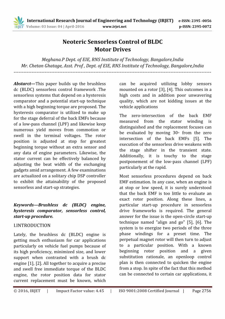
Fig 1. Block diagram of sensorless control using hysteresis comparator and Plots of phase lag to various rotor speeds under a variation of the cut-off frequency.
II. SENSORLESS CONTROL USING HYSTERESIS COMPARATOR
Fig. 1 demonstrates the piece outline of a sensorless control by utilizing a hysteresis comparator strategy for a car fuel pump application. It comprises of the LPFs for smothering the high exchanging recurrence swells, hysteresis comparators for producing three-stage replacement signals, and a gating signals generator for creating six PWM signals. Subsequent to detecting the three-stage terminal voltages, each of the three-stage terminal voltages is nourished into a LPF to stifle the high exchanging recurrence swell or clamor. As just two periods of the BLDC engine are invigorated whenever, the back EMF can be measured from its terminal voltage in the time of an open stage (60◦). Amid the two-stage conduction period (120◦), the main distinction between the back EMF and its terminal voltage is a stator impedance voltage drop, which might be significantly little contrasted and the dc voltage source. In this manner, the waveform of the terminal voltage is almost the same as that Of the back EMF. The terminal voltages can be utilized to recognize the recompense purposes of the BLDC engine rather than the back EMFs at the proposed sensorless control. Fig. 1 demonstrates the plot of the stage slack for different rotor speeds under a variety of the cut-off recurrence of the LPF. As the rotor speed expands, the rate commitment of the stage slack to the general period increments. The slack will irritate current arrangement with the back EMF and will bring about significant issues for replacement at fast. The stage slack in recompense can create critical throbbing torques in such drive which may bring about motions of the rotor speed, and create additional copper misfortunes. In this paper, the cut-off recurrence of the LPF is decided on 2.5 kHz by considering both the stage slack and Consonant conveyance of the
International Research Journal of Engineering and Technology (IRJET) e-ISSN: 2395 -0056
Volume: 03 Issue: 04 | April-2016 www.irjet.net p-ISSN: 2395-0072
© 2016, IRJET | Impact Factor value: 4.45 | ISO 9001:2008 Certified Journal | Page 2758
back EMF. The hysteresis comparator is utilized to adjust for the stage Slack of the back EMFs because of the LPF with a specific end goal to decide the appropriate replacement arrangement of the inverter as indicated by the rotor position. Likewise, it can keep various yield moves by high recurrence swells in the terminal voltages. The yields of the three-stage hysteresis comparators get to be three recompense signals (Za, Zb, Zc ), and after that six gating signs can be produced through some rationale comparisons.
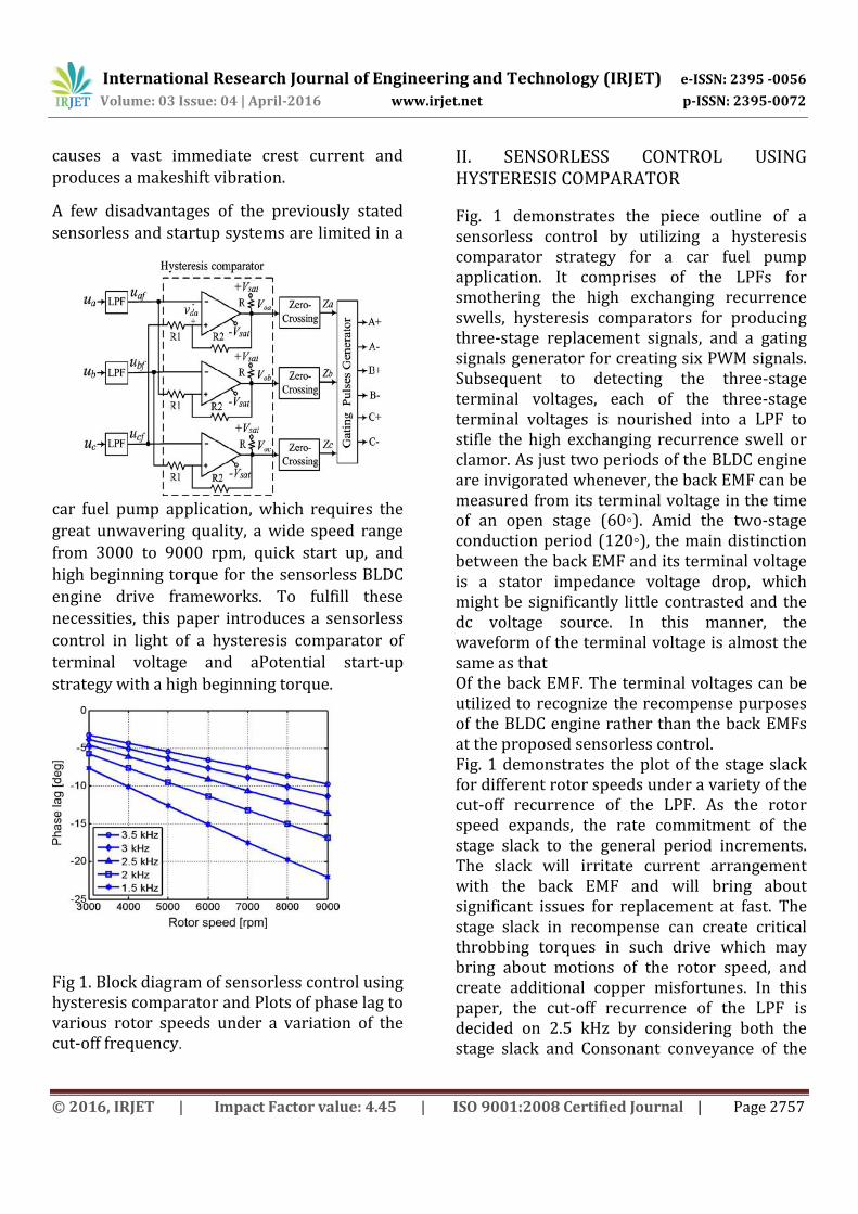
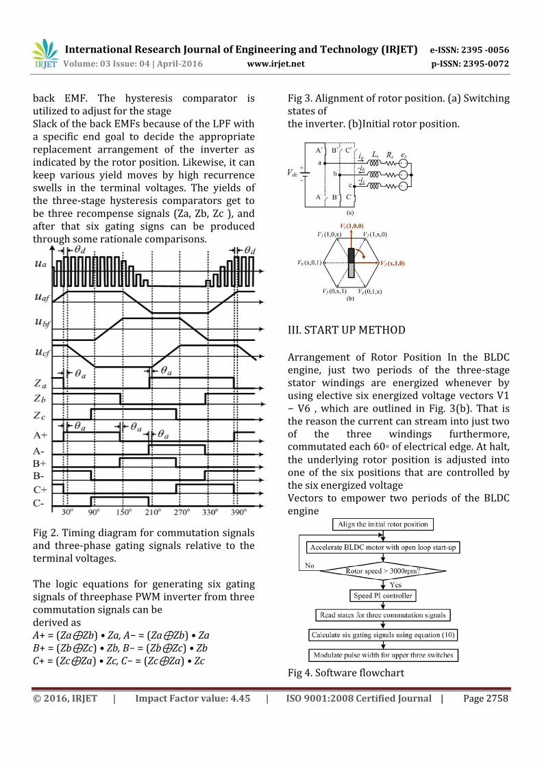
Fig 2. Timing diagram for commutation signals and three-phase gating signals relative to the terminal voltages. The logic equations for generating six gating signals of threephase PWM inverter from three commutation signals can be derived as A+ = (Za⊕Zb) • Za, A− = (Za⊕Zb) • Za B+ = (Zb⊕Zc) • Zb, B− = (Zb⊕Zc) • Zb C+ = (Zc⊕Za) • Zc, C− = (Zc⊕Za) • Zc
Fig 3. Alignment of rotor position. (a) Switching states of the inverter. (b)Initial rotor position.
III. START UP METHOD Arrangement of Rotor Position In the BLDC engine, just two periods of the three-stage stator windings are energized whenever by using elective six energized voltage vectors V1 − V6 , which are outlined in Fig. 3(b). That is the reason the current can stream into just two of the three windings furthermore, commutated each 60◦ of electrical edge. At halt, the underlying rotor position is adjusted into one of the six positions that are controlled by the six energized voltage Vectors to empower two periods of the BLDC engine
Fig 4. Software flowchart
International Research Journal of Engineering and Technology (IRJET) e-ISSN: 2395 -0056
Volume: 03 Issue: 04 | April-2016 www.irjet.net p-ISSN: 2395-0072
© 2016, IRJET | Impact Factor value: 4.45 | ISO 9001:2008 Certified Journal | Page 2759
IV. EXPERIMENTAL RESULTS
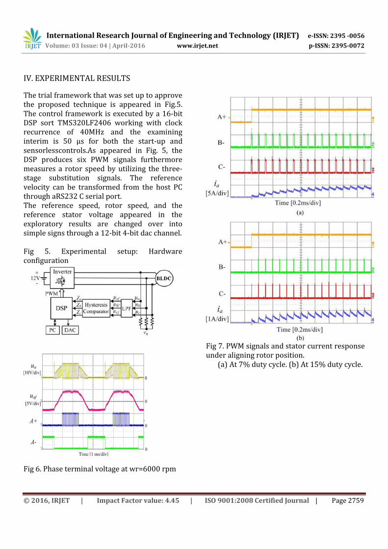
The trial framework that was set up to approve the proposed technique is appeared in Fig.5. The control framework is executed by a 16-bit DSP sort TMS320LF2406 working with clock recurrence of 40MHz and the examining interim is 50 μs for both the start-up and sensorlesscontrols.As appeared in Fig. 5, the DSP produces six PWM signals furthermore measures a rotor speed by utilizing the three-stage substitution signals. The reference velocity can be transformed from the host PC through aRS232 C serial port. The reference speed, rotor speed, and the reference stator voltage appeared in the exploratory results are changed over into simple signs through a 12-bit 4-bit dac channel. Fig 5. Experimental setup: Hardware configuration
Fig 6. Phase terminal voltage at wr=6000 rpm
Fig 7. PWM signals and stator current response under aligning rotor position.
(a) At 7% duty cycle. (b) At 15% duty cycle.
International Research Journal of Engineering and Technology (IRJET) e-ISSN: 2395 -0056
Volume: 03 Issue: 04 | April-2016 www.irjet.net p-ISSN: 2395-0072
© 2016, IRJET | Impact Factor value: 4.45 | ISO 9001:2008 Certified Journal | Page 2760
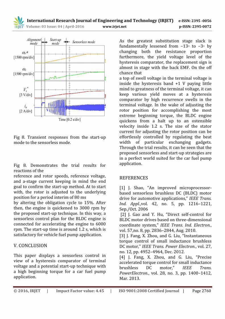
Fig 8. Transient responses from the start-up mode to the sensorless mode.
Fig 8. Demonstrates the trial results for reactions of the reference and rotor speeds, reference voltage, and a-stage current keeping in mind the end goal to confirm the start-up method. At to start with, the rotor is adjusted to the underlying position for a period interim of 80 ms by altering the obligation cycle to 15%. After then, the engine is quickened to 3000 rpm by the proposed start-up technique. In this way, a sensorless control plan for the BLDC engine is connected for accelerating the engine to 6000 rpm. The start-up time is around 1.2 s, which is satisfactory for vehicle fuel pump application. V. CONCLUSION
This paper displays a sensorless control in view of a hysteresis comparator of terminal voltage and a potential start-up technique with a high beginning torque for a car fuel pump application.
As the greatest substitution stage slack is fundamentally lessened from −13◦ to −3◦ by changing both the resistance proportion furthermore, the yield voltage level of the hysteresis comparator, the replacement sign is almost in stage with the back EMF. On the off chance that a top of swell voltage in the terminal voltage is inside the hysteresis band +1 V paying little mind to greatness of the terminal voltage, it can keep various yield moves at a hysteresis comparator by high recurrence swells in the terminal voltage. In the wake of adjusting the rotor position for accomplishing the most extreme beginning torque, the BLDC engine quickens from a halt up to an ostensible velocity inside 1.2 s. The size of the stator current for adjusting the rotor position can be effortlessly controlled by regulating the beat width of particular exchanging gadgets. Through the trial results, it can be seen that the proposed sensorless and start-up strategies are in a perfect world suited for the car fuel pump application.
REFERENCES
[1] J. Shao, “An improved microprocessor-based sensorless brushless DC (BLDC) motor drive for automotive applications,” IEEE Trans. Ind. Appl.,vol. 42, no. 5, pp. 1216–1221, Sep./Oct. 2006 [2] J. Gao and Y. Hu, “Direct self-control for BLDC motor drives based on three-dimensional coordinate system,” IEEE Trans. Ind. Electron., vol. 57,no. 8, pp. 2836–2844, Aug. 2010. [3] J. Fang, X. Zhou, and G. Liu, “Instantaneous torque control of small inductance brushless DC motor,” IEEE Trans. Power Electron., vol. 27, no. 12, pp. 4952–4964, Dec. 2012. [4] J. Fang, X. Zhou, and G. Liu, “Precise accelerated torque control for small inductance brushless DC motor,” IEEE Trans. PowerElectron., vol. 28, no. 3, pp. 1400–1412, Mar. 2013.
International Research Journal of Engineering and Technology (IRJET) e-ISSN: 2395 -0056
Volume: 03 Issue: 04 | April-2016 www.irjet.net p-ISSN: 2395-0072
© 2016, IRJET | Impact Factor value: 4.45 | ISO 9001:2008 Certified Journal | Page 2761
[5] N. Matsui, “Sensorless PM brushless dc motor drives,” IEEE Trans. Ind. Electron., vol. 43, no. 2, pp. 300–308, Apr. 1996. [6] S. Ogasawara and H. Akagi, “An approach to position sensorless drive for brushless DCmotors,” IEEE Trans. Ind. Appl., vol. 27, no. 5, pp. 928–933, Sep./Oct. 1991.
Related Documents