ND-45670 (E) ISSUE 2 PART OF STOCK # 151901 Feature Programming Manual DECEMBER, 1997 NEC America, Inc. ®

Welcome message from author
This document is posted to help you gain knowledge. Please leave a comment to let me know what you think about it! Share it to your friends and learn new things together.
Transcript
ND-45670 (E)ISSUE 2
PART OF STOCK # 151901
Feature Programming Manual
DECEMBER, 1997
NEC America, Inc.
®
LIABILITY DISCLAIMER
NEC America, Inc. reserves the right to change the specifications,functions, or features, at any time, without notice.
NEC America, Inc. has prepared this document for use by its em-ployees and customers. The information contained herein is theproperty of NEC America, Inc. and shall not be reproduced withoutprior written approval from NEC America, Inc.
NEAX and Dterm are registered trademarks of NEC Corporation.
Copyright 1997
NEC America, Inc.
Printed in the U.S.A.
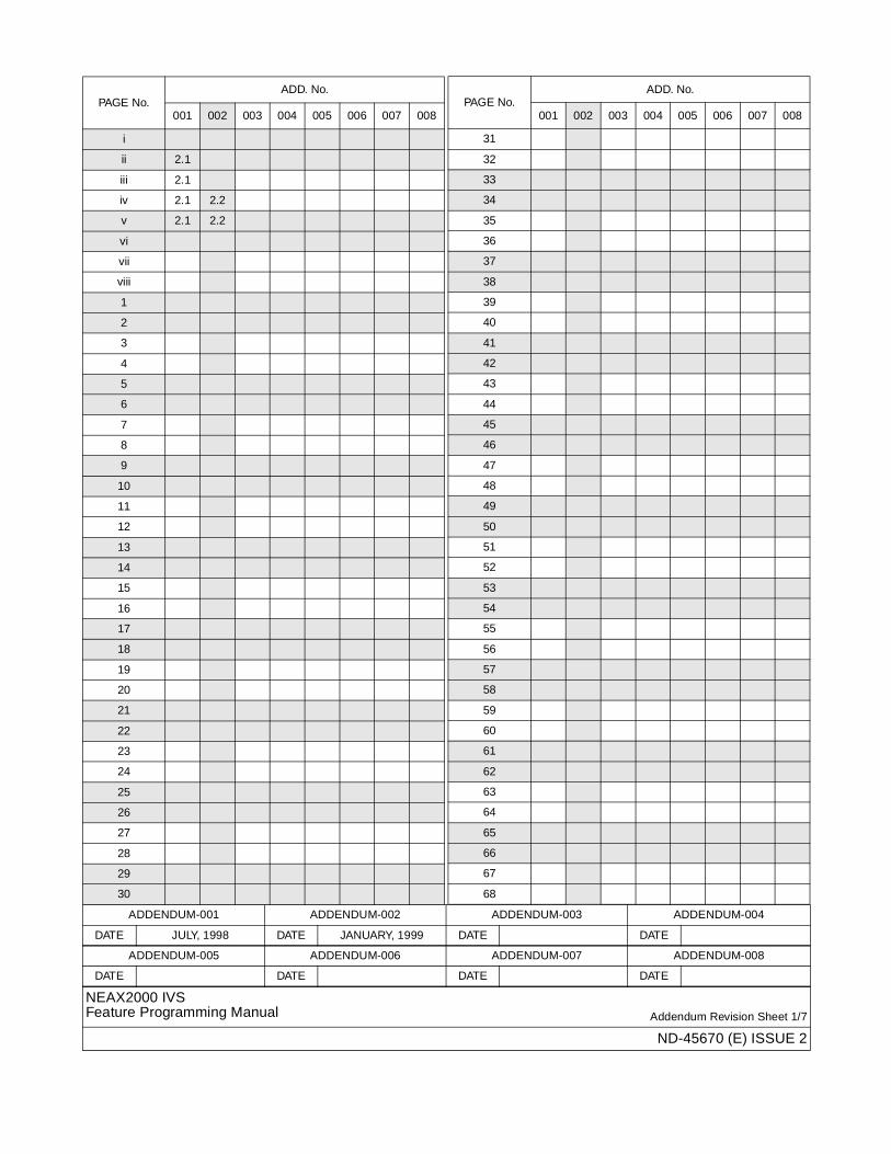
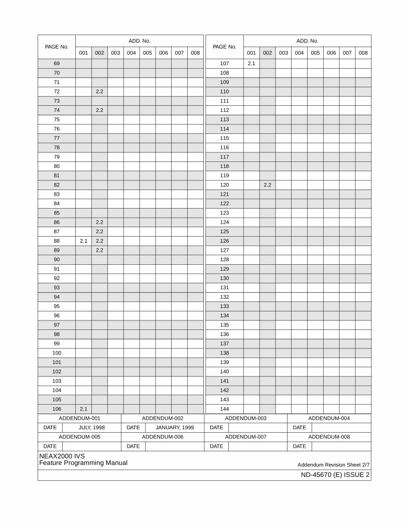
ADDENDUM-001 ADDENDUM-002 ADDENDUM-003 ADDENDUM-004
DATE JULY, 1998 DATE JANUARY, 1999 DATE DATE
ADDENDUM-005 ADDENDUM-006 ADDENDUM-007 ADDENDUM-008
DATE DATE DATE DATE
NEAX2000 IVSFeature Programming Manual Addendum Revision Sheet 1/7
ND-45670 (E) ISSUE 2
PAGE No.ADD. No.
001 002 003 004 005 006 007 008
i
ii 2.1
iii 2.1
iv 2.1 2.2
v 2.1 2.2
vi
vii
viii
1
2
3
4
5
6
7
8
9
10
11
12
13
14
15
16
17
18
19
20
21
22
23
24
25
26
27
28
29
30
31
32
33
34
35
36
37
38
39
40
41
42
43
44
45
46
47
48
49
50
51
52
53
54
55
56
57
58
59
60
61
62
63
64
65
66
67
68
PAGE No.ADD. No.
001 002 003 004 005 006 007 008
ADDENDUM-001 ADDENDUM-002 ADDENDUM-003 ADDENDUM-004
DATE JULY, 1998 DATE JANUARY, 1999 DATE DATE
ADDENDUM-005 ADDENDUM-006 ADDENDUM-007 ADDENDUM-008
DATE DATE DATE DATE
NEAX2000 IVSFeature Programming Manual Addendum Revision Sheet 2/7
ND-45670 (E) ISSUE 2
69
70
71
72 2.2
73
74 2.2
75
76
77
78
79
80
81
82
83
84
85
86 2.2
87 2.2
88 2.1 2.2
89 2.2
90
91
92
93
94
95
96
97
98
99
100
101
102
103
104
105
106 2.1
PAGE No.ADD. No.
001 002 003 004 005 006 007 008
107 2.1
108
109
110
111
112
113
114
115
116
117
118
119
120 2.2
121
122
123
124
125
126
127
128
129
130
131
132
133
134
135
136
137
138
139
140
141
142
143
144
PAGE No.ADD. No.
001 002 003 004 005 006 007 008
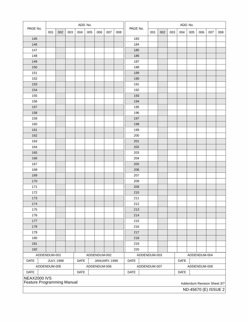
ADDENDUM-001 ADDENDUM-002 ADDENDUM-003 ADDENDUM-004
DATE JULY, 1998 DATE JANUARY, 1999 DATE DATE
ADDENDUM-005 ADDENDUM-006 ADDENDUM-007 ADDENDUM-008
DATE DATE DATE DATE
NEAX2000 IVSFeature Programming Manual Addendum Revision Sheet 3/7
ND-45670 (E) ISSUE 2
145
146
147
148
149
150
151
152
153
154
155
156
157
158
159
160
161
162
163
164
165
166
167
168
169
170
171
172
173
174
175
176
177
178
179
180
181
182
PAGE No.ADD. No.
001 002 003 004 005 006 007 008
183
184
185
186
187
188
189
190
191
192
193
194
195
196
197
198
199
200
201
202
203
204
205
206
207
208
209
210
211
212
213
214
215
216
217
218
219
220
PAGE No.ADD. No.
001 002 003 004 005 006 007 008
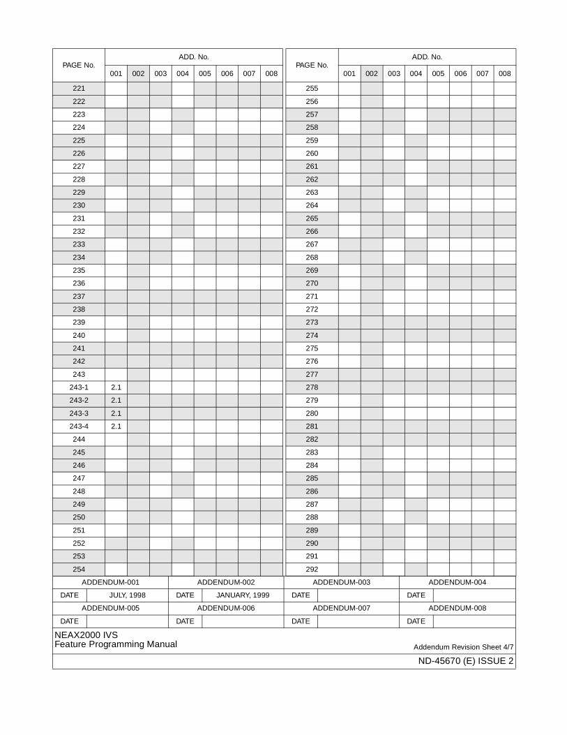
ADDENDUM-001 ADDENDUM-002 ADDENDUM-003 ADDENDUM-004
DATE JULY, 1998 DATE JANUARY, 1999 DATE DATE
ADDENDUM-005 ADDENDUM-006 ADDENDUM-007 ADDENDUM-008
DATE DATE DATE DATE
NEAX2000 IVSFeature Programming Manual Addendum Revision Sheet 4/7
ND-45670 (E) ISSUE 2
221
222
223
224
225
226
227
228
229
230
231
232
233
234
235
236
237
238
239
240
241
242
243
243-1 2.1
243-2 2.1
243-3 2.1
243-4 2.1
244
245
246
247
248
249
250
251
252
253
254
PAGE No.ADD. No.
001 002 003 004 005 006 007 008
255
256
257
258
259
260
261
262
263
264
265
266
267
268
269
270
271
272
273
274
275
276
277
278
279
280
281
282
283
284
285
286
287
288
289
290
291
292
PAGE No.ADD. No.
001 002 003 004 005 006 007 008
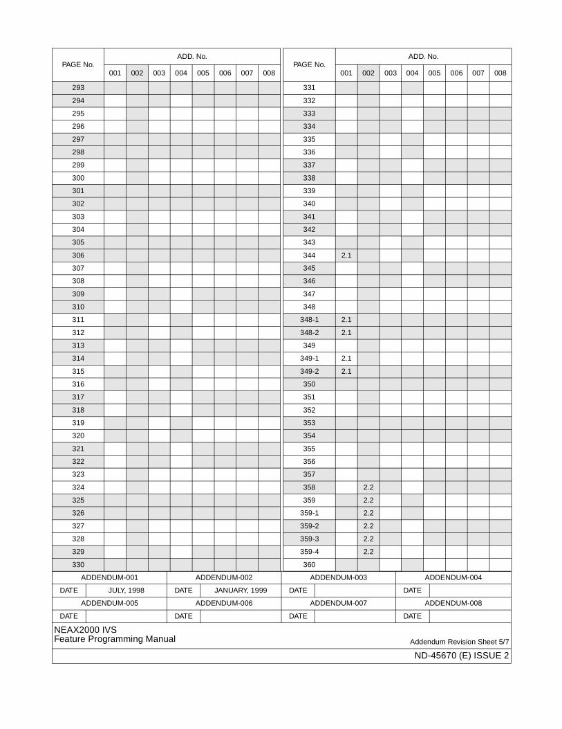
ADDENDUM-001 ADDENDUM-002 ADDENDUM-003 ADDENDUM-004
DATE JULY, 1998 DATE JANUARY, 1999 DATE DATE
ADDENDUM-005 ADDENDUM-006 ADDENDUM-007 ADDENDUM-008
DATE DATE DATE DATE
NEAX2000 IVSFeature Programming Manual Addendum Revision Sheet 5/7
ND-45670 (E) ISSUE 2
293
294
295
296
297
298
299
300
301
302
303
304
305
306
307
308
309
310
311
312
313
314
315
316
317
318
319
320
321
322
323
324
325
326
327
328
329
330
PAGE No.ADD. No.
001 002 003 004 005 006 007 008
331
332
333
334
335
336
337
338
339
340
341
342
343
344 2.1
345
346
347
348
348-1 2.1
348-2 2.1
349
349-1 2.1
349-2 2.1
350
351
352
353
354
355
356
357
358 2.2
359 2.2
359-1 2.2
359-2 2.2
359-3 2.2
359-4 2.2
360
PAGE No.ADD. No.
001 002 003 004 005 006 007 008
ADDENDUM-001 ADDENDUM-002 ADDENDUM-003 ADDENDUM-004
DATE JULY, 1998 DATE JANUARY, 1999 DATE DATE
ADDENDUM-005 ADDENDUM-006 ADDENDUM-007 ADDENDUM-008
DATE DATE DATE DATE
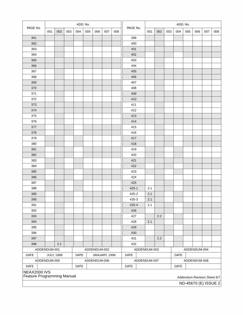
NEAX2000 IVSFeature Programming Manual Addendum Revision Sheet 6/7
ND-45670 (E) ISSUE 2
361
362
363
364
365
366
367
368
369
370
371
372
373
374
375
376
377
378
379
380
381
382
383
384
385
386
387
388
389
390
391
392
393
394
395
396
397
398 2.2
PAGE No.ADD. No.
001 002 003 004 005 006 007 008
399
400
401
402
403
404
405
406
407
408
409
410
411
412
413
414
415
416
417
418
419
420
421
422
423
424
425
425-1 2.1
425-2 2.1
425-3 2.1
425-4 2.1
426
427 2.2
428 2.1
429
430
431 2.2
432
PAGE No.ADD. No.
001 002 003 004 005 006 007 008
ADDENDUM-001 ADDENDUM-002 ADDENDUM-003 ADDENDUM-004
DATE JULY, 1998 DATE JANUARY, 1999 DATE DATE
ADDENDUM-005 ADDENDUM-006 ADDENDUM-007 ADDENDUM-008
DATE DATE DATE DATE
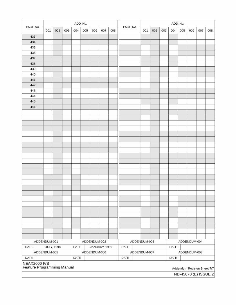
NEAX2000 IVSFeature Programming Manual Addendum Revision Sheet 7/7
ND-45670 (E) ISSUE 2
433
434
435
436
437
438
439
440
441
442
443
444
445
446
PAGE No.ADD. No.
001 002 003 004 005 006 007 008PAGE No.
ADD. No.
001 002 003 004 005 006 007 008
ND-45670 (E)ISSUE 2
DECEMBER, 1997
NEAX2000 IVSFeature Programming Manual
TABLE OF CONTENTS
Page
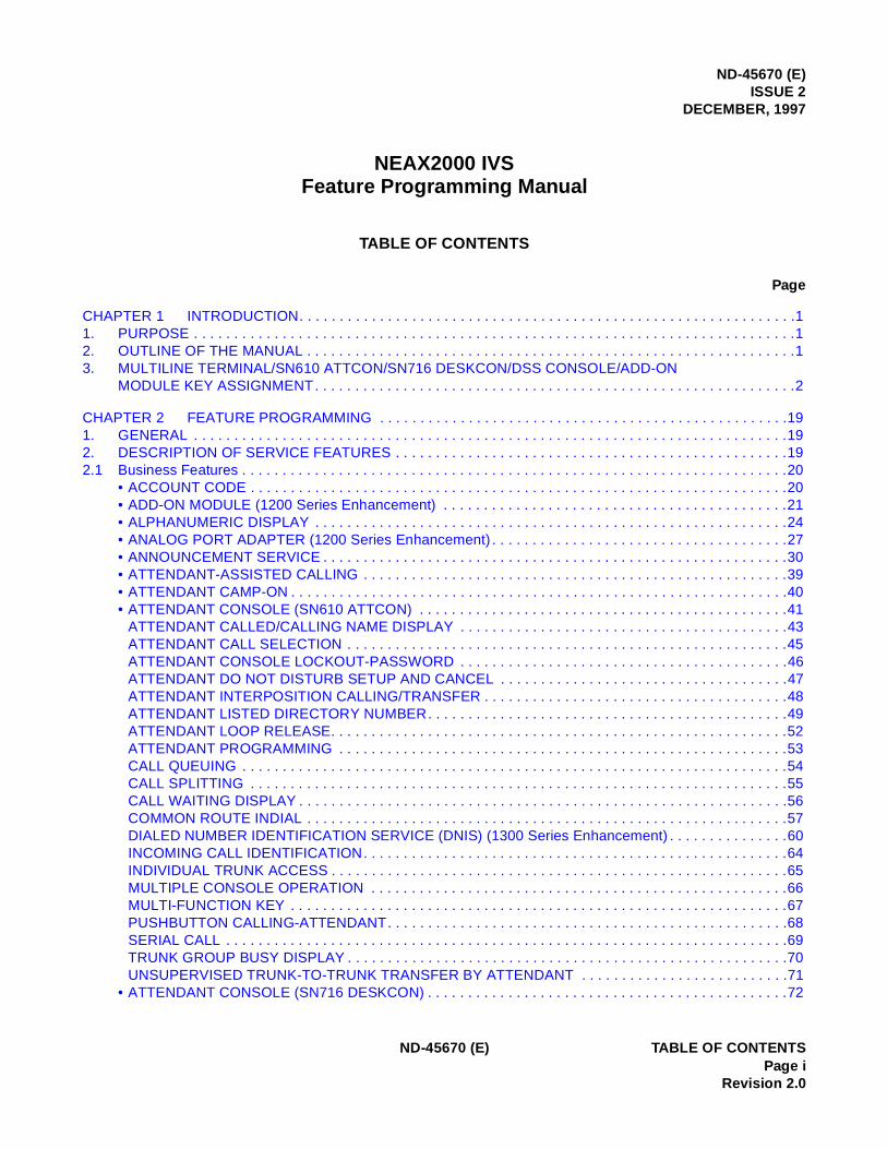
CHAPTER 1 INTRODUCTION. . . . . . . . . . . . . . . . . . . . . . . . . . . . . . . . . . . . . . . . . . . . . . . . . . . . . . . . . . . . . .11. PURPOSE . . . . . . . . . . . . . . . . . . . . . . . . . . . . . . . . . . . . . . . . . . . . . . . . . . . . . . . . . . . . . . . . . . . . . . . . . . .12. OUTLINE OF THE MANUAL . . . . . . . . . . . . . . . . . . . . . . . . . . . . . . . . . . . . . . . . . . . . . . . . . . . . . . . . . . . . .13. MULTILINE TERMINAL/SN610 ATTCON/SN716 DESKCON/DSS CONSOLE/ADD-ON
MODULE KEY ASSIGNMENT. . . . . . . . . . . . . . . . . . . . . . . . . . . . . . . . . . . . . . . . . . . . . . . . . . . . . . . . . . . .2
CHAPTER 2 FEATURE PROGRAMMING . . . . . . . . . . . . . . . . . . . . . . . . . . . . . . . . . . . . . . . . . . . . . . . . . . .191. GENERAL . . . . . . . . . . . . . . . . . . . . . . . . . . . . . . . . . . . . . . . . . . . . . . . . . . . . . . . . . . . . . . . . . . . . . . . . . .192. DESCRIPTION OF SERVICE FEATURES . . . . . . . . . . . . . . . . . . . . . . . . . . . . . . . . . . . . . . . . . . . . . . . . .192.1 Business Features . . . . . . . . . . . . . . . . . . . . . . . . . . . . . . . . . . . . . . . . . . . . . . . . . . . . . . . . . . . . . . . . . . . .20
• ACCOUNT CODE . . . . . . . . . . . . . . . . . . . . . . . . . . . . . . . . . . . . . . . . . . . . . . . . . . . . . . . . . . . . . . . . . . .20• ADD-ON MODULE (1200 Series Enhancement) . . . . . . . . . . . . . . . . . . . . . . . . . . . . . . . . . . . . . . . . . . .21• ALPHANUMERIC DISPLAY . . . . . . . . . . . . . . . . . . . . . . . . . . . . . . . . . . . . . . . . . . . . . . . . . . . . . . . . . . .24• ANALOG PORT ADAPTER (1200 Series Enhancement) . . . . . . . . . . . . . . . . . . . . . . . . . . . . . . . . . . . . .27• ANNOUNCEMENT SERVICE . . . . . . . . . . . . . . . . . . . . . . . . . . . . . . . . . . . . . . . . . . . . . . . . . . . . . . . . . .30• ATTENDANT-ASSISTED CALLING . . . . . . . . . . . . . . . . . . . . . . . . . . . . . . . . . . . . . . . . . . . . . . . . . . . . .39• ATTENDANT CAMP-ON . . . . . . . . . . . . . . . . . . . . . . . . . . . . . . . . . . . . . . . . . . . . . . . . . . . . . . . . . . . . . .40• ATTENDANT CONSOLE (SN610 ATTCON) . . . . . . . . . . . . . . . . . . . . . . . . . . . . . . . . . . . . . . . . . . . . . .41
ATTENDANT CALLED/CALLING NAME DISPLAY . . . . . . . . . . . . . . . . . . . . . . . . . . . . . . . . . . . . . . . . .43ATTENDANT CALL SELECTION . . . . . . . . . . . . . . . . . . . . . . . . . . . . . . . . . . . . . . . . . . . . . . . . . . . . . . .45ATTENDANT CONSOLE LOCKOUT-PASSWORD . . . . . . . . . . . . . . . . . . . . . . . . . . . . . . . . . . . . . . . . .46ATTENDANT DO NOT DISTURB SETUP AND CANCEL . . . . . . . . . . . . . . . . . . . . . . . . . . . . . . . . . . . .47ATTENDANT INTERPOSITION CALLING/TRANSFER . . . . . . . . . . . . . . . . . . . . . . . . . . . . . . . . . . . . . .48ATTENDANT LISTED DIRECTORY NUMBER. . . . . . . . . . . . . . . . . . . . . . . . . . . . . . . . . . . . . . . . . . . . .49ATTENDANT LOOP RELEASE. . . . . . . . . . . . . . . . . . . . . . . . . . . . . . . . . . . . . . . . . . . . . . . . . . . . . . . . .52ATTENDANT PROGRAMMING . . . . . . . . . . . . . . . . . . . . . . . . . . . . . . . . . . . . . . . . . . . . . . . . . . . . . . . .53CALL QUEUING . . . . . . . . . . . . . . . . . . . . . . . . . . . . . . . . . . . . . . . . . . . . . . . . . . . . . . . . . . . . . . . . . . . .54CALL SPLITTING . . . . . . . . . . . . . . . . . . . . . . . . . . . . . . . . . . . . . . . . . . . . . . . . . . . . . . . . . . . . . . . . . . .55CALL WAITING DISPLAY . . . . . . . . . . . . . . . . . . . . . . . . . . . . . . . . . . . . . . . . . . . . . . . . . . . . . . . . . . . . .56COMMON ROUTE INDIAL . . . . . . . . . . . . . . . . . . . . . . . . . . . . . . . . . . . . . . . . . . . . . . . . . . . . . . . . . . . .57DIALED NUMBER IDENTIFICATION SERVICE (DNIS) (1300 Series Enhancement) . . . . . . . . . . . . . . .60INCOMING CALL IDENTIFICATION. . . . . . . . . . . . . . . . . . . . . . . . . . . . . . . . . . . . . . . . . . . . . . . . . . . . .64INDIVIDUAL TRUNK ACCESS . . . . . . . . . . . . . . . . . . . . . . . . . . . . . . . . . . . . . . . . . . . . . . . . . . . . . . . . .65MULTIPLE CONSOLE OPERATION . . . . . . . . . . . . . . . . . . . . . . . . . . . . . . . . . . . . . . . . . . . . . . . . . . . .66MULTI-FUNCTION KEY . . . . . . . . . . . . . . . . . . . . . . . . . . . . . . . . . . . . . . . . . . . . . . . . . . . . . . . . . . . . . .67PUSHBUTTON CALLING-ATTENDANT. . . . . . . . . . . . . . . . . . . . . . . . . . . . . . . . . . . . . . . . . . . . . . . . . .68SERIAL CALL . . . . . . . . . . . . . . . . . . . . . . . . . . . . . . . . . . . . . . . . . . . . . . . . . . . . . . . . . . . . . . . . . . . . . .69TRUNK GROUP BUSY DISPLAY . . . . . . . . . . . . . . . . . . . . . . . . . . . . . . . . . . . . . . . . . . . . . . . . . . . . . . .70UNSUPERVISED TRUNK-TO-TRUNK TRANSFER BY ATTENDANT . . . . . . . . . . . . . . . . . . . . . . . . . .71
• ATTENDANT CONSOLE (SN716 DESKCON) . . . . . . . . . . . . . . . . . . . . . . . . . . . . . . . . . . . . . . . . . . . . .72
ND-45670 (E) TABLE OF CONTENTSPage i
Revision 2.0
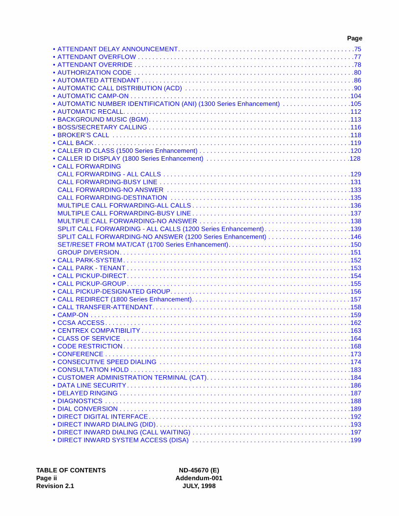
TABLE OF CONTENTS ND-45670 (E)Page ii Addendum-001Revision 2.1 JULY, 1998
Page
• ATTENDANT DELAY ANNOUNCEMENT. . . . . . . . . . . . . . . . . . . . . . . . . . . . . . . . . . . . . . . . . . . . . . . . .75• ATTENDANT OVERFLOW . . . . . . . . . . . . . . . . . . . . . . . . . . . . . . . . . . . . . . . . . . . . . . . . . . . . . . . . . . . .77• ATTENDANT OVERRIDE . . . . . . . . . . . . . . . . . . . . . . . . . . . . . . . . . . . . . . . . . . . . . . . . . . . . . . . . . . . . .78• AUTHORIZATION CODE . . . . . . . . . . . . . . . . . . . . . . . . . . . . . . . . . . . . . . . . . . . . . . . . . . . . . . . . . . . . .80• AUTOMATED ATTENDANT . . . . . . . . . . . . . . . . . . . . . . . . . . . . . . . . . . . . . . . . . . . . . . . . . . . . . . . . . . .86• AUTOMATIC CALL DISTRIBUTION (ACD) . . . . . . . . . . . . . . . . . . . . . . . . . . . . . . . . . . . . . . . . . . . . . . .90• AUTOMATIC CAMP-ON . . . . . . . . . . . . . . . . . . . . . . . . . . . . . . . . . . . . . . . . . . . . . . . . . . . . . . . . . . . . .104• AUTOMATIC NUMBER IDENTIFICATION (ANI) (1300 Series Enhancement) . . . . . . . . . . . . . . . . . . .105• AUTOMATIC RECALL. . . . . . . . . . . . . . . . . . . . . . . . . . . . . . . . . . . . . . . . . . . . . . . . . . . . . . . . . . . . . . .112• BACKGROUND MUSIC (BGM). . . . . . . . . . . . . . . . . . . . . . . . . . . . . . . . . . . . . . . . . . . . . . . . . . . . . . . .113• BOSS/SECRETARY CALLING . . . . . . . . . . . . . . . . . . . . . . . . . . . . . . . . . . . . . . . . . . . . . . . . . . . . . . . .116• BROKER’S CALL . . . . . . . . . . . . . . . . . . . . . . . . . . . . . . . . . . . . . . . . . . . . . . . . . . . . . . . . . . . . . . . . . .118• CALL BACK. . . . . . . . . . . . . . . . . . . . . . . . . . . . . . . . . . . . . . . . . . . . . . . . . . . . . . . . . . . . . . . . . . . . . . .119• CALLER ID CLASS (1500 Series Enhancement) . . . . . . . . . . . . . . . . . . . . . . . . . . . . . . . . . . . . . . . . . .120• CALLER ID DISPLAY (1800 Series Enhancement) . . . . . . . . . . . . . . . . . . . . . . . . . . . . . . . . . . . . . . . .128• CALL FORWARDING
CALL FORWARDING - ALL CALLS . . . . . . . . . . . . . . . . . . . . . . . . . . . . . . . . . . . . . . . . . . . . . . . . . . . .129CALL FORWARDING-BUSY LINE . . . . . . . . . . . . . . . . . . . . . . . . . . . . . . . . . . . . . . . . . . . . . . . . . . . . .131CALL FORWARDING-NO ANSWER . . . . . . . . . . . . . . . . . . . . . . . . . . . . . . . . . . . . . . . . . . . . . . . . . . .133CALL FORWARDING-DESTINATION . . . . . . . . . . . . . . . . . . . . . . . . . . . . . . . . . . . . . . . . . . . . . . . . . .135MULTIPLE CALL FORWARDING-ALL CALLS . . . . . . . . . . . . . . . . . . . . . . . . . . . . . . . . . . . . . . . . . . . .136MULTIPLE CALL FORWARDING-BUSY LINE . . . . . . . . . . . . . . . . . . . . . . . . . . . . . . . . . . . . . . . . . . . .137MULTIPLE CALL FORWARDING-NO ANSWER . . . . . . . . . . . . . . . . . . . . . . . . . . . . . . . . . . . . . . . . . .138SPLIT CALL FORWARDING - ALL CALLS (1200 Series Enhancement) . . . . . . . . . . . . . . . . . . . . . . . .139SPLIT CALL FORWARDING-NO ANSWER (1200 Series Enhancement) . . . . . . . . . . . . . . . . . . . . . . .146SET/RESET FROM MAT/CAT (1700 Series Enhancement). . . . . . . . . . . . . . . . . . . . . . . . . . . . . . . . . .150GROUP DIVERSION. . . . . . . . . . . . . . . . . . . . . . . . . . . . . . . . . . . . . . . . . . . . . . . . . . . . . . . . . . . . . . . .151
• CALL PARK-SYSTEM . . . . . . . . . . . . . . . . . . . . . . . . . . . . . . . . . . . . . . . . . . . . . . . . . . . . . . . . . . . . . . .152• CALL PARK - TENANT . . . . . . . . . . . . . . . . . . . . . . . . . . . . . . . . . . . . . . . . . . . . . . . . . . . . . . . . . . . . . .153• CALL PICKUP-DIRECT. . . . . . . . . . . . . . . . . . . . . . . . . . . . . . . . . . . . . . . . . . . . . . . . . . . . . . . . . . . . . .154• CALL PICKUP-GROUP. . . . . . . . . . . . . . . . . . . . . . . . . . . . . . . . . . . . . . . . . . . . . . . . . . . . . . . . . . . . . .155• CALL PICKUP-DESIGNATED GROUP. . . . . . . . . . . . . . . . . . . . . . . . . . . . . . . . . . . . . . . . . . . . . . . . . .156• CALL REDIRECT (1800 Series Enhancement). . . . . . . . . . . . . . . . . . . . . . . . . . . . . . . . . . . . . . . . . . . . 157• CALL TRANSFER-ATTENDANT. . . . . . . . . . . . . . . . . . . . . . . . . . . . . . . . . . . . . . . . . . . . . . . . . . . . . . .158• CAMP-ON . . . . . . . . . . . . . . . . . . . . . . . . . . . . . . . . . . . . . . . . . . . . . . . . . . . . . . . . . . . . . . . . . . . . . . . .159• CCSA ACCESS. . . . . . . . . . . . . . . . . . . . . . . . . . . . . . . . . . . . . . . . . . . . . . . . . . . . . . . . . . . . . . . . . . . .162• CENTREX COMPATIBILITY . . . . . . . . . . . . . . . . . . . . . . . . . . . . . . . . . . . . . . . . . . . . . . . . . . . . . . . . . .163• CLASS OF SERVICE . . . . . . . . . . . . . . . . . . . . . . . . . . . . . . . . . . . . . . . . . . . . . . . . . . . . . . . . . . . . . . .164• CODE RESTRICTION . . . . . . . . . . . . . . . . . . . . . . . . . . . . . . . . . . . . . . . . . . . . . . . . . . . . . . . . . . . . . . .168• CONFERENCE . . . . . . . . . . . . . . . . . . . . . . . . . . . . . . . . . . . . . . . . . . . . . . . . . . . . . . . . . . . . . . . . . . . .173• CONSECUTIVE SPEED DIALING . . . . . . . . . . . . . . . . . . . . . . . . . . . . . . . . . . . . . . . . . . . . . . . . . . . . .174• CONSULTATION HOLD . . . . . . . . . . . . . . . . . . . . . . . . . . . . . . . . . . . . . . . . . . . . . . . . . . . . . . . . . . . . .183• CUSTOMER ADMINISTRATION TERMINAL (CAT). . . . . . . . . . . . . . . . . . . . . . . . . . . . . . . . . . . . . . . .184• DATA LINE SECURITY . . . . . . . . . . . . . . . . . . . . . . . . . . . . . . . . . . . . . . . . . . . . . . . . . . . . . . . . . . . . . .186• DELAYED RINGING . . . . . . . . . . . . . . . . . . . . . . . . . . . . . . . . . . . . . . . . . . . . . . . . . . . . . . . . . . . . . . . .187• DIAGNOSTICS . . . . . . . . . . . . . . . . . . . . . . . . . . . . . . . . . . . . . . . . . . . . . . . . . . . . . . . . . . . . . . . . . . . .188• DIAL CONVERSION . . . . . . . . . . . . . . . . . . . . . . . . . . . . . . . . . . . . . . . . . . . . . . . . . . . . . . . . . . . . . . . .189• DIRECT DIGITAL INTERFACE. . . . . . . . . . . . . . . . . . . . . . . . . . . . . . . . . . . . . . . . . . . . . . . . . . . . . . . .192• DIRECT INWARD DIALING (DID). . . . . . . . . . . . . . . . . . . . . . . . . . . . . . . . . . . . . . . . . . . . . . . . . . . . . .193• DIRECT INWARD DIALING (CALL WAITING) . . . . . . . . . . . . . . . . . . . . . . . . . . . . . . . . . . . . . . . . . . . .197• DIRECT INWARD SYSTEM ACCESS (DISA) . . . . . . . . . . . . . . . . . . . . . . . . . . . . . . . . . . . . . . . . . . . .199
ND-45670 (E) TABLE OF CONTENTSAddendum-001 Page iii
JULY, 1998 Revision 2.1
Page
• DIRECT INWARD TERMINATION (DIT). . . . . . . . . . . . . . . . . . . . . . . . . . . . . . . . . . . . . . . . . . . . . . . . .205• DIRECT OUTWARD DIALING (DOD) . . . . . . . . . . . . . . . . . . . . . . . . . . . . . . . . . . . . . . . . . . . . . . . . . . .206• DIRECT STATION SELECTION/BUSY LAMP FIELD (DSS/BLF) CONSOLE . . . . . . . . . . . . . . . . . . . .209• DISTINCTIVE RINGING . . . . . . . . . . . . . . . . . . . . . . . . . . . . . . . . . . . . . . . . . . . . . . . . . . . . . . . . . . . . .210• DO NOT DISTURB . . . . . . . . . . . . . . . . . . . . . . . . . . . . . . . . . . . . . . . . . . . . . . . . . . . . . . . . . . . . . . . . .212• DUAL HOLD . . . . . . . . . . . . . . . . . . . . . . . . . . . . . . . . . . . . . . . . . . . . . . . . . . . . . . . . . . . . . . . . . . . . . .214• E & M TIE LINE ACCESS . . . . . . . . . . . . . . . . . . . . . . . . . . . . . . . . . . . . . . . . . . . . . . . . . . . . . . . . . . . .215• ENHANCED 911 . . . . . . . . . . . . . . . . . . . . . . . . . . . . . . . . . . . . . . . . . . . . . . . . . . . . . . . . . . . . . . . . . . .222• EXECUTIVE CALLING . . . . . . . . . . . . . . . . . . . . . . . . . . . . . . . . . . . . . . . . . . . . . . . . . . . . . . . . . . . . . .225• EXECUTIVE OVERRIDE. . . . . . . . . . . . . . . . . . . . . . . . . . . . . . . . . . . . . . . . . . . . . . . . . . . . . . . . . . . . .226• EXTERNAL PAGING WITH MEET-ME . . . . . . . . . . . . . . . . . . . . . . . . . . . . . . . . . . . . . . . . . . . . . . . . . .227• FAX ARRIVAL INDICATOR. . . . . . . . . . . . . . . . . . . . . . . . . . . . . . . . . . . . . . . . . . . . . . . . . . . . . . . . . . .231• FLEXIBLE LINE KEY ASSIGNMENT . . . . . . . . . . . . . . . . . . . . . . . . . . . . . . . . . . . . . . . . . . . . . . . . . . .233• FLEXIBLE NUMBERING PLAN. . . . . . . . . . . . . . . . . . . . . . . . . . . . . . . . . . . . . . . . . . . . . . . . . . . . . . . .237• FLEXIBLE RINGING ASSIGNMENT. . . . . . . . . . . . . . . . . . . . . . . . . . . . . . . . . . . . . . . . . . . . . . . . . . . .239• FORCED ACCOUNT CODE . . . . . . . . . . . . . . . . . . . . . . . . . . . . . . . . . . . . . . . . . . . . . . . . . . . . . . . . . .240• GROUP CALL-AUTOMATIC CONFERENCE (6/10 PARTY) ASSIGNMENT. . . . . . . . . . . . . . . . . . . 243-1• GROUP CALL-2 WAY CALLING. . . . . . . . . . . . . . . . . . . . . . . . . . . . . . . . . . . . . . . . . . . . . . . . . . . . . 243-3• GROUP LISTENING . . . . . . . . . . . . . . . . . . . . . . . . . . . . . . . . . . . . . . . . . . . . . . . . . . . . . . . . . . . . . . . .244• HOLD
CALL HOLD. . . . . . . . . . . . . . . . . . . . . . . . . . . . . . . . . . . . . . . . . . . . . . . . . . . . . . . . . . . . . . . . . . . . . . .245EXCLUSIVE HOLD . . . . . . . . . . . . . . . . . . . . . . . . . . . . . . . . . . . . . . . . . . . . . . . . . . . . . . . . . . . . . . . . .246
• HOTLINE . . . . . . . . . . . . . . . . . . . . . . . . . . . . . . . . . . . . . . . . . . . . . . . . . . . . . . . . . . . . . . . . . . . . . . . . .247• INDIVIDUAL ATTENDANT ACCESS . . . . . . . . . . . . . . . . . . . . . . . . . . . . . . . . . . . . . . . . . . . . . . . . . . .250• INTERCEPT ANNOUNCEMENT. . . . . . . . . . . . . . . . . . . . . . . . . . . . . . . . . . . . . . . . . . . . . . . . . . . . . . .251• INTERCOM
MANUAL INTERCOM . . . . . . . . . . . . . . . . . . . . . . . . . . . . . . . . . . . . . . . . . . . . . . . . . . . . . . . . . . . . . . .252AUTOMATIC INTERCOM . . . . . . . . . . . . . . . . . . . . . . . . . . . . . . . . . . . . . . . . . . . . . . . . . . . . . . . . . . . .253DIAL INTERCOM. . . . . . . . . . . . . . . . . . . . . . . . . . . . . . . . . . . . . . . . . . . . . . . . . . . . . . . . . . . . . . . . . . .255
• INTERNAL TONE / VOICE SIGNALING . . . . . . . . . . . . . . . . . . . . . . . . . . . . . . . . . . . . . . . . . . . . . . . . .257• INTERNAL ZONE PAGING WITH MEET-ME . . . . . . . . . . . . . . . . . . . . . . . . . . . . . . . . . . . . . . . . . . . . .259• LAST NUMBER REDIAL . . . . . . . . . . . . . . . . . . . . . . . . . . . . . . . . . . . . . . . . . . . . . . . . . . . . . . . . . . . . .261• LEAST COST ROUTING-3/6-DIGIT . . . . . . . . . . . . . . . . . . . . . . . . . . . . . . . . . . . . . . . . . . . . . . . . . . . .262• LINE LOCKOUT . . . . . . . . . . . . . . . . . . . . . . . . . . . . . . . . . . . . . . . . . . . . . . . . . . . . . . . . . . . . . . . . . . .276• LINE PRESELECTION . . . . . . . . . . . . . . . . . . . . . . . . . . . . . . . . . . . . . . . . . . . . . . . . . . . . . . . . . . . . . .277• MAINTENANCE ADMINISTRATION TERMINAL (MAT). . . . . . . . . . . . . . . . . . . . . . . . . . . . . . . . . . . . .278• MAT: FAULT MESSAGE . . . . . . . . . . . . . . . . . . . . . . . . . . . . . . . . . . . . . . . . . . . . . . . . . . . . . . . . . . . . .280• MAT: PEG COUNT . . . . . . . . . . . . . . . . . . . . . . . . . . . . . . . . . . . . . . . . . . . . . . . . . . . . . . . . . . . . . . . . .281• MAT: REMOVE AND RESTORE. . . . . . . . . . . . . . . . . . . . . . . . . . . . . . . . . . . . . . . . . . . . . . . . . . . . . . .282• MAT: STATION/TRUNK STATUS . . . . . . . . . . . . . . . . . . . . . . . . . . . . . . . . . . . . . . . . . . . . . . . . . . . . . .283• MESSAGE CENTER INTERFACE (MCI) . . . . . . . . . . . . . . . . . . . . . . . . . . . . . . . . . . . . . . . . . . . . . . . .284• MESSAGE REMINDER. . . . . . . . . . . . . . . . . . . . . . . . . . . . . . . . . . . . . . . . . . . . . . . . . . . . . . . . . . . . . .285• MISCELLANEOUS TRUNK ACCESS
CODE CALLING EQUIPMENT ACCESS . . . . . . . . . . . . . . . . . . . . . . . . . . . . . . . . . . . . . . . . . . . . . . . .289DICTATION EQUIPMENT ACCESS . . . . . . . . . . . . . . . . . . . . . . . . . . . . . . . . . . . . . . . . . . . . . . . . . . . .291FOREIGN EXCHANGE (FX) ACCESS . . . . . . . . . . . . . . . . . . . . . . . . . . . . . . . . . . . . . . . . . . . . . . . . . .292RADIO PAGING EQUIPMENT ACCESS . . . . . . . . . . . . . . . . . . . . . . . . . . . . . . . . . . . . . . . . . . . . . . . .293WIDE AREA TELEPHONE SERVICE (WATS) ACCESS . . . . . . . . . . . . . . . . . . . . . . . . . . . . . . . . . . . .298
• MULTILINE TERMINAL ATTENDANT POSITION . . . . . . . . . . . . . . . . . . . . . . . . . . . . . . . . . . . . . . . . .299• MUSIC ON HOLD . . . . . . . . . . . . . . . . . . . . . . . . . . . . . . . . . . . . . . . . . . . . . . . . . . . . . . . . . . . . . . . . . .306• NIGHT SERVICE
TABLE OF CONTENTS ND-45670 (E)Page iv Addendum-002Revision 2.2 DECEMBER, 1998
Page
ATTENDANT NIGHT TRANSFER. . . . . . . . . . . . . . . . . . . . . . . . . . . . . . . . . . . . . . . . . . . . . . . . . . . . . .314CALL REROUTING . . . . . . . . . . . . . . . . . . . . . . . . . . . . . . . . . . . . . . . . . . . . . . . . . . . . . . . . . . . . . . . . .315DAY/NIGHT MODE CHANGE BY ATTENDANT CONSOLE . . . . . . . . . . . . . . . . . . . . . . . . . . . . . . . . .316DAY/NIGHT MODE CHANGE BY STATION DIALING . . . . . . . . . . . . . . . . . . . . . . . . . . . . . . . . . . . . . .317NIGHT CONNECTION-FIXED. . . . . . . . . . . . . . . . . . . . . . . . . . . . . . . . . . . . . . . . . . . . . . . . . . . . . . . . .318NIGHT CONNECTION-FLEXIBLE . . . . . . . . . . . . . . . . . . . . . . . . . . . . . . . . . . . . . . . . . . . . . . . . . . . . .319TRUNK ANSWER ANY STATION (TAS) . . . . . . . . . . . . . . . . . . . . . . . . . . . . . . . . . . . . . . . . . . . . . . . .320
• OFF-HOOK ALARM . . . . . . . . . . . . . . . . . . . . . . . . . . . . . . . . . . . . . . . . . . . . . . . . . . . . . . . . . . . . . . . .324• OFF PREMISES EXTENSION . . . . . . . . . . . . . . . . . . . . . . . . . . . . . . . . . . . . . . . . . . . . . . . . . . . . . . . .325• PAD LOCK (1300 Series Enhancement). . . . . . . . . . . . . . . . . . . . . . . . . . . . . . . . . . . . . . . . . . . . . . . . .326• PERIODIC TIME INDICATION TONE . . . . . . . . . . . . . . . . . . . . . . . . . . . . . . . . . . . . . . . . . . . . . . . . . . .335• POOLED LINE ACCESS . . . . . . . . . . . . . . . . . . . . . . . . . . . . . . . . . . . . . . . . . . . . . . . . . . . . . . . . . . . . .336• POWER FAILURE TRANSFER. . . . . . . . . . . . . . . . . . . . . . . . . . . . . . . . . . . . . . . . . . . . . . . . . . . . . . . .338• PRIORITY CALL . . . . . . . . . . . . . . . . . . . . . . . . . . . . . . . . . . . . . . . . . . . . . . . . . . . . . . . . . . . . . . . . . . .339• PRIVACY/PRIVACY RELEASE. . . . . . . . . . . . . . . . . . . . . . . . . . . . . . . . . . . . . . . . . . . . . . . . . . . . . . . .340• PRIVATE LINES . . . . . . . . . . . . . . . . . . . . . . . . . . . . . . . . . . . . . . . . . . . . . . . . . . . . . . . . . . . . . . . . . . .341• PROPRIETARY MULTILINE TERMINAL . . . . . . . . . . . . . . . . . . . . . . . . . . . . . . . . . . . . . . . . . . . . . . . .342
AUTOMATIC IDLE RETURN. . . . . . . . . . . . . . . . . . . . . . . . . . . . . . . . . . . . . . . . . . . . . . . . . . . . . . . . . .346CALLING NAME AND NUMBER. . . . . . . . . . . . . . . . . . . . . . . . . . . . . . . . . . . . . . . . . . . . . . . . . . . . . . .347DIGITAL SINGLE LINE . . . . . . . . . . . . . . . . . . . . . . . . . . . . . . . . . . . . . . . . . . . . . . . . . . . . . . . . . . . . . .348DYNAMIC DIAL PAD (1900 Series Enhancement) . . . . . . . . . . . . . . . . . . . . . . . . . . . . . . . . . . . . . . . 348-1MULTIPLE LINE OPERATION . . . . . . . . . . . . . . . . . . . . . . . . . . . . . . . . . . . . . . . . . . . . . . . . . . . . . . . .349MUTE KEY (1900 Series Enhancement). . . . . . . . . . . . . . . . . . . . . . . . . . . . . . . . . . . . . . . . . . . . . . . 349-1OFF-HOOK VOICE ANNOUNCEMENT (1200 Series Enhancement) . . . . . . . . . . . . . . . . . . . . . . . . . .350PRIME LINE PICKUP . . . . . . . . . . . . . . . . . . . . . . . . . . . . . . . . . . . . . . . . . . . . . . . . . . . . . . . . . . . . . . .352RECALL KEY. . . . . . . . . . . . . . . . . . . . . . . . . . . . . . . . . . . . . . . . . . . . . . . . . . . . . . . . . . . . . . . . . . . . . .353RELAY CONTROL FUNCTION. . . . . . . . . . . . . . . . . . . . . . . . . . . . . . . . . . . . . . . . . . . . . . . . . . . . . . . .354RING FREQUENCY CONTROL . . . . . . . . . . . . . . . . . . . . . . . . . . . . . . . . . . . . . . . . . . . . . . . . . . . . . . .356SOFT KEY . . . . . . . . . . . . . . . . . . . . . . . . . . . . . . . . . . . . . . . . . . . . . . . . . . . . . . . . . . . . . . . . . . . . . . . .358
• REMOTE HOLD (1900 Series Release 2 Enhancement) . . . . . . . . . . . . . . . . . . . . . . . . . . . . . . . . . . 359-3• RESIDENT SYSTEM PROGRAM . . . . . . . . . . . . . . . . . . . . . . . . . . . . . . . . . . . . . . . . . . . . . . . . . . . . . .360• RETURN MESSAGE SCHEDULE DISPLAY . . . . . . . . . . . . . . . . . . . . . . . . . . . . . . . . . . . . . . . . . . . . .361• RINGING LINE PICKUP . . . . . . . . . . . . . . . . . . . . . . . . . . . . . . . . . . . . . . . . . . . . . . . . . . . . . . . . . . . . .362• ROUTE ADVANCE . . . . . . . . . . . . . . . . . . . . . . . . . . . . . . . . . . . . . . . . . . . . . . . . . . . . . . . . . . . . . . . . .363• SAVE AND REPEAT . . . . . . . . . . . . . . . . . . . . . . . . . . . . . . . . . . . . . . . . . . . . . . . . . . . . . . . . . . . . . . . .364• SECURITY ALARM . . . . . . . . . . . . . . . . . . . . . . . . . . . . . . . . . . . . . . . . . . . . . . . . . . . . . . . . . . . . . . . . .365• SIX/TEN-PARTY CONFERENCE . . . . . . . . . . . . . . . . . . . . . . . . . . . . . . . . . . . . . . . . . . . . . . . . . . . . . .366• SOFTWARE LINE APPEARANCE . . . . . . . . . . . . . . . . . . . . . . . . . . . . . . . . . . . . . . . . . . . . . . . . . . . . .368• STACK DIAL . . . . . . . . . . . . . . . . . . . . . . . . . . . . . . . . . . . . . . . . . . . . . . . . . . . . . . . . . . . . . . . . . . . . . .369• STATION HUNTING
STATION HUNTING-CIRCULAR . . . . . . . . . . . . . . . . . . . . . . . . . . . . . . . . . . . . . . . . . . . . . . . . . . . . . .370STATION HUNTING-TERMINAL . . . . . . . . . . . . . . . . . . . . . . . . . . . . . . . . . . . . . . . . . . . . . . . . . . . . . .371STATION HUNTING-SECRETARIAL . . . . . . . . . . . . . . . . . . . . . . . . . . . . . . . . . . . . . . . . . . . . . . . . . . .372
• STATION MESSAGE DETAIL RECORDING (SMDR) . . . . . . . . . . . . . . . . . . . . . . . . . . . . . . . . . . . . . .373• STATION SPEED DIALING. . . . . . . . . . . . . . . . . . . . . . . . . . . . . . . . . . . . . . . . . . . . . . . . . . . . . . . . . . .374• STEP CALL . . . . . . . . . . . . . . . . . . . . . . . . . . . . . . . . . . . . . . . . . . . . . . . . . . . . . . . . . . . . . . . . . . . . . . .382• SUPERVISORY CONTROL OF PERIPHERAL EQUIPMENT . . . . . . . . . . . . . . . . . . . . . . . . . . . . . . . .383• SYSTEM SPEED DIALING . . . . . . . . . . . . . . . . . . . . . . . . . . . . . . . . . . . . . . . . . . . . . . . . . . . . . . . . . . .384• TENANT SERVICE . . . . . . . . . . . . . . . . . . . . . . . . . . . . . . . . . . . . . . . . . . . . . . . . . . . . . . . . . . . . . . . . .388• TIE LINE TANDEM SWITCHING . . . . . . . . . . . . . . . . . . . . . . . . . . . . . . . . . . . . . . . . . . . . . . . . . . . . . .390• TIMED QUEUE . . . . . . . . . . . . . . . . . . . . . . . . . . . . . . . . . . . . . . . . . . . . . . . . . . . . . . . . . . . . . . . . . . . .391
ND-45670 (E) TABLE OF CONTENTSAddendum-002 Page v
DECEMBER, 1998 Revision 2.2
Page
• TIMED REMINDER . . . . . . . . . . . . . . . . . . . . . . . . . . . . . . . . . . . . . . . . . . . . . . . . . . . . . . . . . . . . . . . . .392• TRUNK-DIRECT APPEARANCES . . . . . . . . . . . . . . . . . . . . . . . . . . . . . . . . . . . . . . . . . . . . . . . . . . . . .398• TRUNK QUEUING-OUTGOING . . . . . . . . . . . . . . . . . . . . . . . . . . . . . . . . . . . . . . . . . . . . . . . . . . . . . . .401• TRUNK-TO-TRUNK CONNECTION . . . . . . . . . . . . . . . . . . . . . . . . . . . . . . . . . . . . . . . . . . . . . . . . . . . .402• UNIFORM CALL DISTRIBUTION (UCD) WITH OVERFLOW. . . . . . . . . . . . . . . . . . . . . . . . . . . . . . . . .406• UNIFORM NUMBERING-VOICE & DATA. . . . . . . . . . . . . . . . . . . . . . . . . . . . . . . . . . . . . . . . . . . . . . . .416• VARIABLE TIMING PARAMETERS . . . . . . . . . . . . . . . . . . . . . . . . . . . . . . . . . . . . . . . . . . . . . . . . . . . .425• VOICE GUIDE (1900 Series Enhancement) . . . . . . . . . . . . . . . . . . . . . . . . . . . . . . . . . . . . . . . . . . . . 4 25-1• VOICE MAIL INTEGRATION (IN BAND). . . . . . . . . . . . . . . . . . . . . . . . . . . . . . . . . . . . . . . . . . . . . . . . .426• VOICE MAIL TRANSFER . . . . . . . . . . . . . . . . . . . . . . . . . . . . . . . . . . . . . . . . . . . . . . . . . . . . . . . . . . . .429• WHISPER PAGE . . . . . . . . . . . . . . . . . . . . . . . . . . . . . . . . . . . . . . . . . . . . . . . . . . . . . . . . . . . . . . . . . . .431• ASYNCHRONOUS DATA SWITCHING . . . . . . . . . . . . . . . . . . . . . . . . . . . . . . . . . . . . . . . . . . . . . . . . .432
2.2 DATA COMMUNICATIONS FEATURES. . . . . . . . . . . . . . . . . . . . . . . . . . . . . . . . . . . . . . . . . . . . . . . . . .432• DATA HOTLINE. . . . . . . . . . . . . . . . . . . . . . . . . . . . . . . . . . . . . . . . . . . . . . . . . . . . . . . . . . . . . . . . . . . .436• DATA HOTLINE-OUTSIDE . . . . . . . . . . . . . . . . . . . . . . . . . . . . . . . . . . . . . . . . . . . . . . . . . . . . . . . . . . .437• DATA HUNTING . . . . . . . . . . . . . . . . . . . . . . . . . . . . . . . . . . . . . . . . . . . . . . . . . . . . . . . . . . . . . . . . . . .438• DATA INTERFACE-AUTOMATIC ANSWER. . . . . . . . . . . . . . . . . . . . . . . . . . . . . . . . . . . . . . . . . . . . . .440• DO NOT DISTURB-DATA LINE . . . . . . . . . . . . . . . . . . . . . . . . . . . . . . . . . . . . . . . . . . . . . . . . . . . . . . .441• NAILED-DOWN CONNECTION . . . . . . . . . . . . . . . . . . . . . . . . . . . . . . . . . . . . . . . . . . . . . . . . . . . . . . .442• SYNCHRONOUS DATA SWITCHING . . . . . . . . . . . . . . . . . . . . . . . . . . . . . . . . . . . . . . . . . . . . . . . . . .443• TERMINAL ATTRIBUTE DATA ASSIGNMENT . . . . . . . . . . . . . . . . . . . . . . . . . . . . . . . . . . . . . . . . . . .446

This page is for your notes.
TABLE OF CONTENTS ND-45670 (E)Page viRevision 2.0

LIST OF FIGURESFigure Title Page
Figure 1-1 Multiline Terminal Key Numbers . . . . . . . . . . . . . . . . . . . . . . . . . . . . . . . . . . . . . . . . . . . . . . . . . 2Figure 1-2 SN610 ATTCON Key Numbers . . . . . . . . . . . . . . . . . . . . . . . . . . . . . . . . . . . . . . . . . . . . . . . . . 12Figure 1-3 SN716 DESKCON Key Numbers. . . . . . . . . . . . . . . . . . . . . . . . . . . . . . . . . . . . . . . . . . . . . . . . 13Figure 1-4 DSS Console Key Numbers. . . . . . . . . . . . . . . . . . . . . . . . . . . . . . . . . . . . . . . . . . . . . . . . . . . . 14Figure 1-5 Add-On Module Key Numbers . . . . . . . . . . . . . . . . . . . . . . . . . . . . . . . . . . . . . . . . . . . . . . . . . . 16
ND-45492 (E) LIST OF FIGURESPage vii
Revision 2.0

This page is for your notes.
LIST OF FIGURES ND-45492 (E)Page viiiRevision 2.0
nd pro- service,ble
on Pro- For the
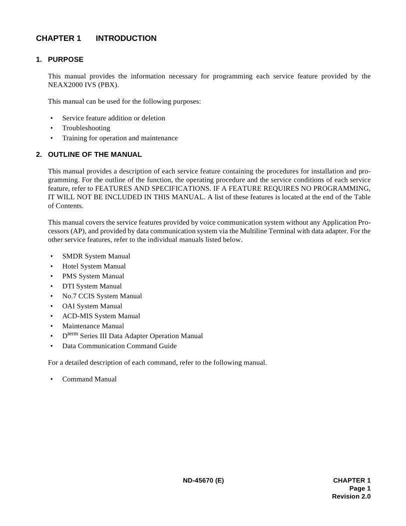
CHAPTER 1 INTRODUCTION
1. PURPOSE
This manual provides the information necessary for programming each service feature provided by theNEAX2000 IVS (PBX).
This manual can be used for the following purposes:
• Service feature addition or deletion• Troubleshooting
• Training for operation and maintenance
2. OUTLINE OF THE MANUAL
This manual provides a description of each service feature containing the procedures for installation agramming. For the outline of the function, the operating procedure and the service conditions of eachfeature, refer to FEATURES AND SPECIFICATIONS. IF A FEATURE REQUIRES NO PROGRAMMINGIT WILL NOT BE INCLUDED IN THIS MANUAL. A list of these features is located at the end of the Taof Contents.
This manual covers the service features provided by voice communication system without any Applicaticessors (AP), and provided by data communication system via the Multiline Terminal with data adapter.other service features, refer to the individual manuals listed below.
• SMDR System Manual
• Hotel System Manual• PMS System Manual
• DTI System Manual• No.7 CCIS System Manual
• OAI System Manual• ACD-MIS System Manual
• Maintenance Manual • Dterm Series III Data Adapter Operation Manual
• Data Communication Command Guide
For a detailed description of each command, refer to the following manual.
• Command Manual
ND-45670 (E) CHAPTER 1Page 1
Revision 2.0
INTRODUCTION
716ent by
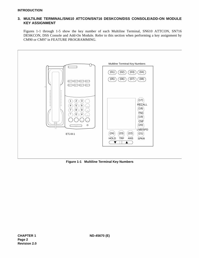
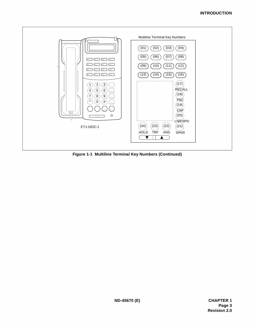
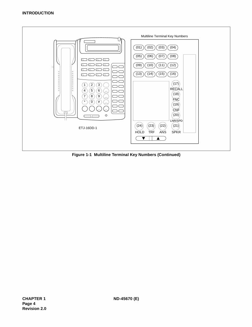
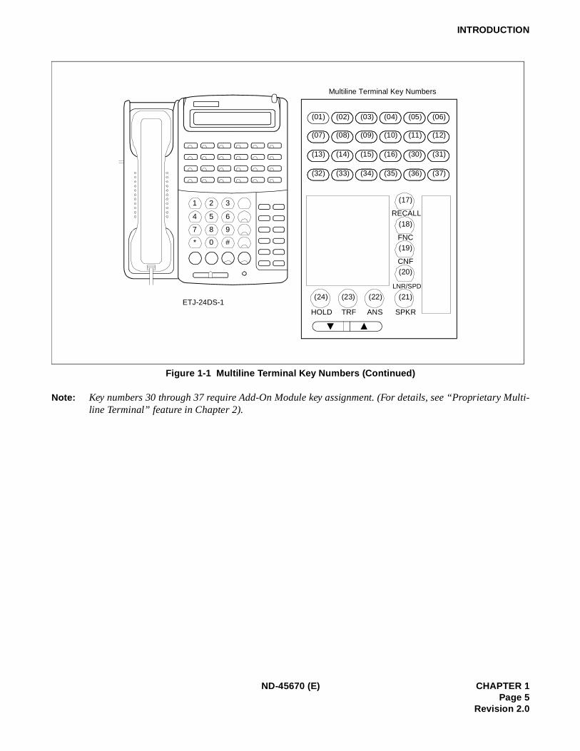
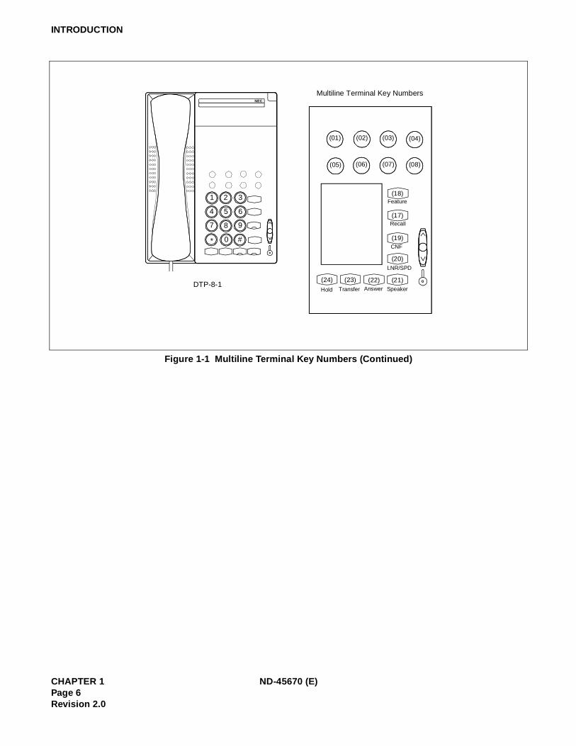
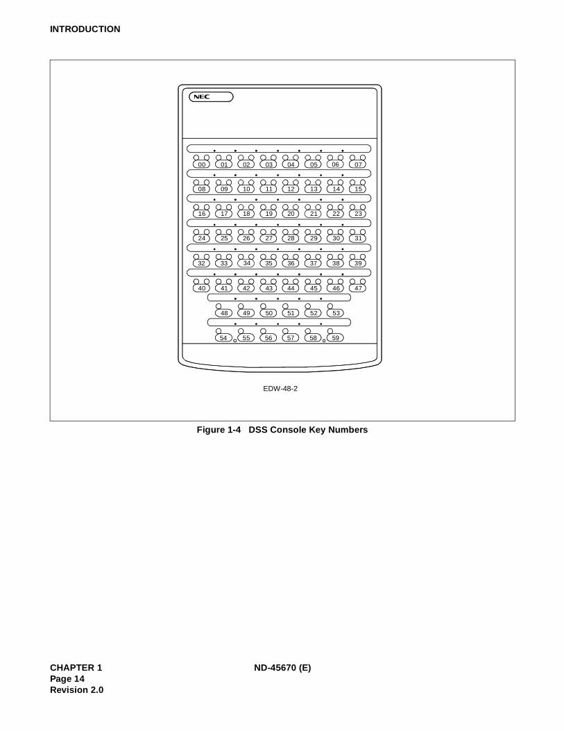
3. MULTILINE TERMINAL/SN610 ATTCON/SN716 DESKCON/DSS CONSOLE/ADD-ON MODULEKEY ASSIGNMENT
Figures 1-1 through 1-5 show the key number of each Multiline Terminal, SN610 ATTCON, SNDESKCON, DSS Console and Add-On Module. Refer to this section when performing a key assignmCM90 or CM97 in FEATURE PROGRAMMING.
Figure 1-1 Multiline Terminal Key Numbers
1 2 3
4 5 6
7 8 9
* 0 #
(01)
RECALL
FNC
CNF
LNR/SPD
SPKRANSTRFHOLD
ETJ-8-1
Multiline Terminal Key Numbers
(05)
(02)
(06)
(03)
(07)
(04)
(08)
(17)
(18)
(19)
(20)
(21) (22) (23)(24)
CHAPTER 1 ND-45670 (E)Page 2Revision 2.0
INTRODUCTION
Figure 1-1 Multiline Terminal Key Numbers (Continued)
1 2 3
4 5 6
7 8 9
* 0 #
(01)
RECALL
FNC
CNF
LNR/SPD
SPKRANSTRFHOLD
ETJ-16DC-1
Multiline Terminal Key Numbers
(05)
(02)
(06)
(03)
(07)
(04)
(08)
(17)
(18)
(19)
(20)
(21) (22) (23) (24)
(09)
(13)
(10)
(14)
(11)
(15)
(12)
(16)
ND-45670 (E) CHAPTER 1Page 3
Revision 2.0
INTRODUCTION
Figure 1-1 Multiline Terminal Key Numbers (Continued)
1 2 3
4 5 6
7 8 9
* 0 #
RECALL
FNC
CNF
LNR/SPD
SPKRANSTRFHOLDETJ-16DD-1
Multiline Terminal Key Numbers
(01)
(05)
(09)
(13)
(02)
(06)
(10)
(14)
(03)
(07)
(11)
(15)
(04)
(08)
(12)
(16)
(17)
(18)
(19)
(20)
(21)(22)(23)(24)
CHAPTER 1 ND-45670 (E)Page 4Revision 2.0
INTRODUCTION
Multi-
Figure 1-1 Multiline Terminal Key Numbers (Continued)
Note: Key numbers 30 through 37 require Add-On Module key assignment. (For details, see “Proprietary line Terminal” feature in Chapter 2).
1 2 3
4 5 6
7 8 9
* 0 #
RECALL
FNC
CNF
LNR/SPD
SPKRANSTRFHOLDETJ-24DS-1
Multiline Terminal Key Numbers
(01)
(07)
(13)
(32)
(02)
(08)
(14)
(33)
(03)
(09)
(15)
(34)
(04)
(10)
(16)
(35)
(05)
(11)
(30)
(36)
(06)
(12)
(31)
(37)
(17)
(18)
(19)
(20)
(21)(22)(23)(24)
ND-45670 (E) CHAPTER 1Page 5
Revision 2.0
INTRODUCTION
Figure 1-1 Multiline Terminal Key Numbers (Continued)
Multiline Terminal Key Numbers
Recall
Feature
CNF
LNR/SPD
SpeakerAnswerTransferHold
(19)
(17)
(18)
(20)
(03) (04)(01) (02)
(05) (06) (07) (08)
(21)(22)(23)(24)
1
4
7
2
5
8
0 #*
9
6
3
NEC
DTP-8-1
CHAPTER 1 ND-45670 (E)Page 6Revision 2.0
INTRODUCTION
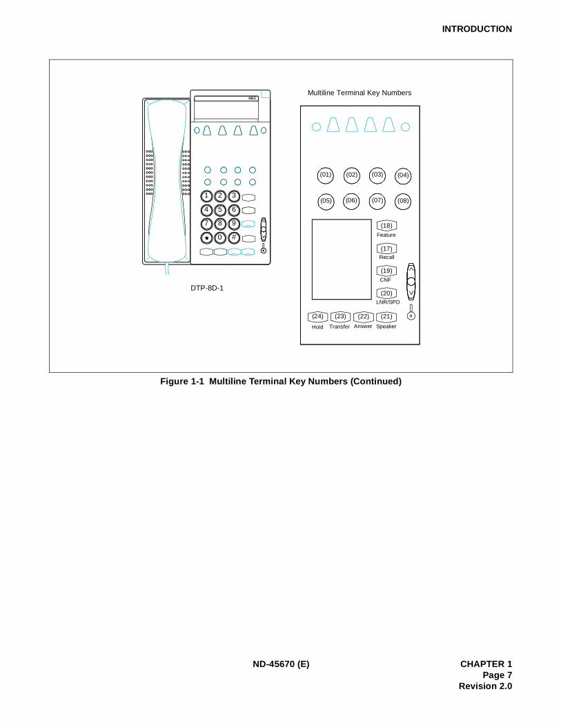
Figure 1-1 Multiline Terminal Key Numbers (Continued)
Multiline Terminal Key Numbers
SpeakerAnswerTransferHold
(03) (04)(01) (02)
(05) (06) (07) (08)
Recall
(17)
CNF
(19)
LNR/SPD
(20)
(21)(22)(23)(24)
Feature
(18)
1
4
7
2
5
8
0 #
9
6
3
NEC
DTP-8D-1
ND-45670 (E) CHAPTER 1Page 7
Revision 2.0
INTRODUCTION
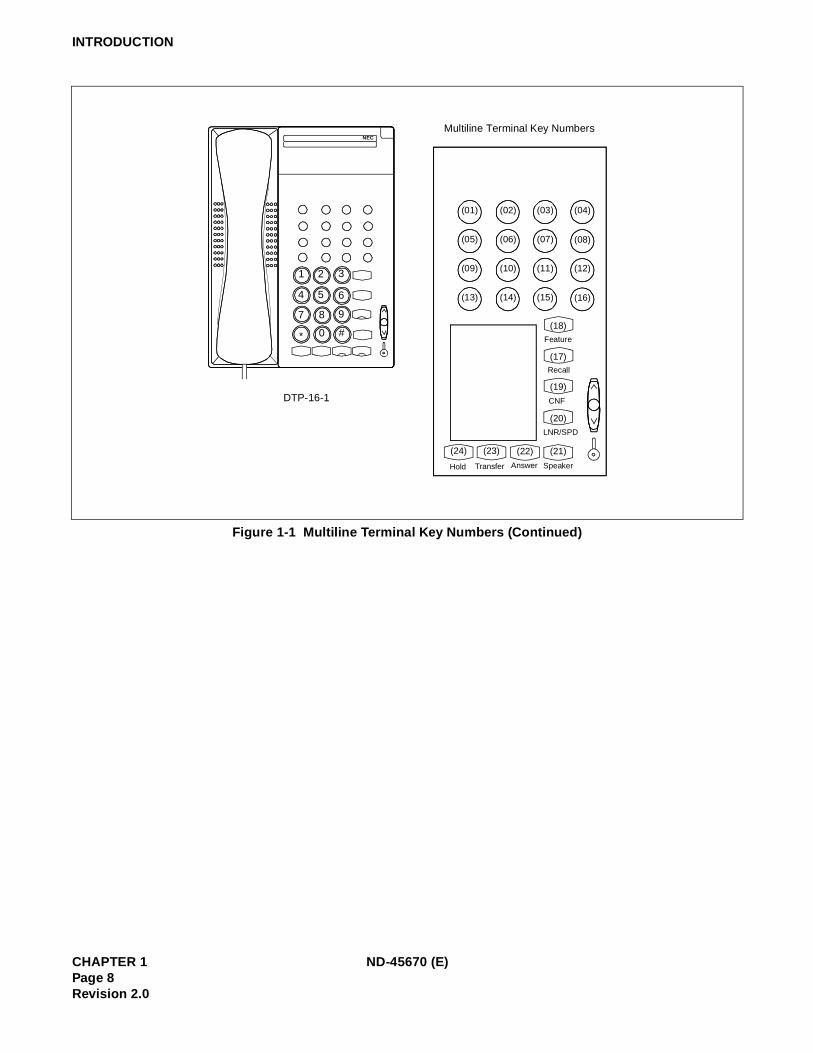
Figure 1-1 Multiline Terminal Key Numbers (Continued)
1
4
7
2
5
0 #*
3
NEC
DTP-16-1
Multiline Terminal Key Numbers
SpeakerAnswerTransferHold
(07) (08)(05) (06)
(11) (12)(09) (10)
(15) (16)(13) (14)
(03) (04)(01) (02)
Recall
(17)
CNF
(19)
LNR/SPD
(20)
(21)(22)(23)(24)
Feature
(18)9
6
8
CHAPTER 1 ND-45670 (E)Page 8Revision 2.0
INTRODUCTION
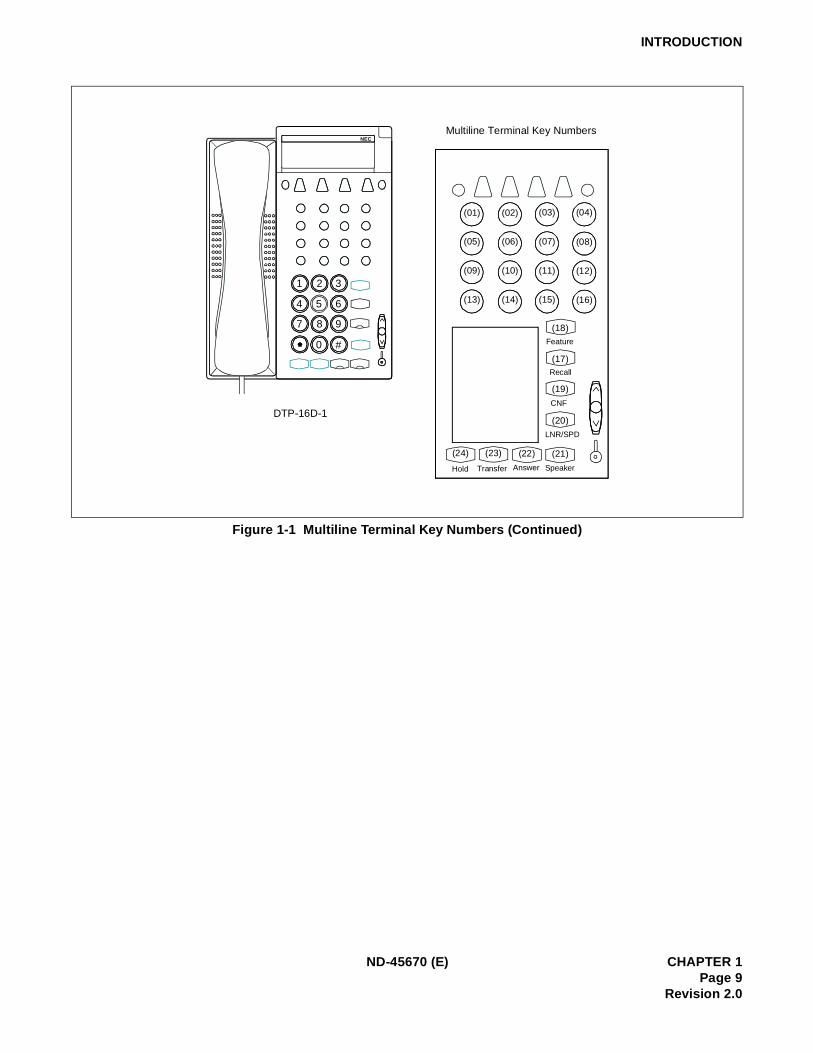
Figure 1-1 Multiline Terminal Key Numbers (Continued)
Multiline Terminal Key Numbers
SpeakerAnswerTransferHold
(07) (08)(05) (06)
(11) (12)(09) (10)
(15) (16)(13) (14)
(03) (04)(01) (02)
Recall
(17)
CNF
(19)
LNR/SPD
(20)
(21)(22)(23)(24)
Feature
(18)
1
4
7
2
8
0 #
9
6
3
NEC
DTP-16D-1
5
ND-45670 (E) CHAPTER 1Page 9
Revision 2.0
INTRODUCTION
ds:
y assign-
Figure 1-1 Multiline Terminal Key Numbers (Continued)
Note: Key numbers 30 through 37 can be used as either Line/Trunk/Feature key or DSS key. In other wor
• Line/Trunk key, Feature key =16 + DSS key =16or
• Line/Trunk key, Feature key =24 + DSS key =8
When key numbers 30 through 37 are used as the Line/Trunk/Feature keys, the Add-on Module kement is required. (For details, see “Proprietary Multiline Terminal” feature in Chapter 2).
Recall
Feature
CNF
LNR/SPD
SpeakerAnswerTransferHold
(19)
(17)
(18)
(20)
(03) (04)(01) (02)
(05) (06) (07) (08)
(09) (10) (11) (12)
(13) (14) (15) (16)
(21)(22)(23)(24)
(30)
(32)
(34)
(36)
(31)
(33)
(35)
(37)1
4
7
2
5
8
0 #*
9
6
3
NEC
DTP-32-1
CHAPTER 1 ND-45670 (E)Page 10Revision 2.0
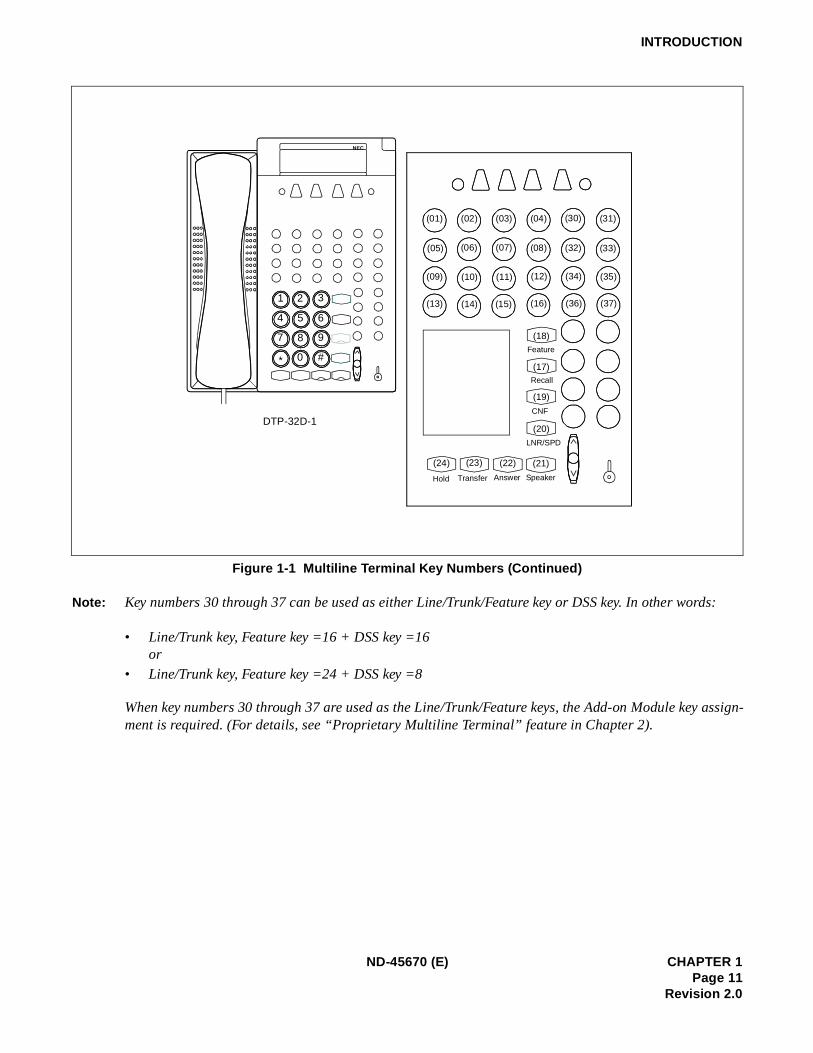
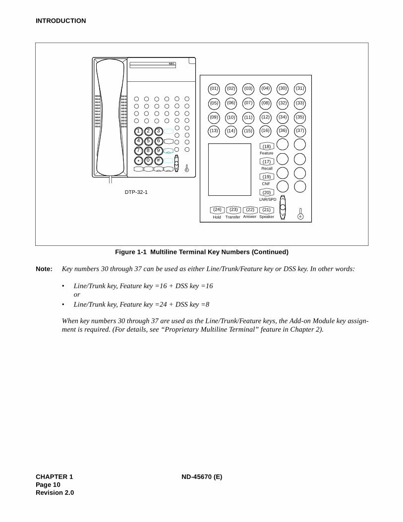
INTRODUCTION
ds:
y assign-
Figure 1-1 Multiline Terminal Key Numbers (Continued)
Note: Key numbers 30 through 37 can be used as either Line/Trunk/Feature key or DSS key. In other wor
• Line/Trunk key, Feature key =16 + DSS key =16or
• Line/Trunk key, Feature key =24 + DSS key =8
When key numbers 30 through 37 are used as the Line/Trunk/Feature keys, the Add-on Module kement is required. (For details, see “Proprietary Multiline Terminal” feature in Chapter 2).
1
4
7
2
5
8
0 #*
9
6
3
NEC
Recall
Feature
CNF
LNR/SPD
SpeakerAnswerTransferHold
(19)
(17)
(18)
(20)
(03) (04)(01) (02)
(05) (06) (07) (08)
(09) (10) (11) (12)
(13) (14) (15) (16)
(21)(22)(23)(24)
(30)
(32)
(34)
(36)
(31)
(33)
(35)
(37)
DTP-32D-1
ND-45670 (E) CHAPTER 1Page 11
Revision 2.0
INTRODUCTION
ents forviding
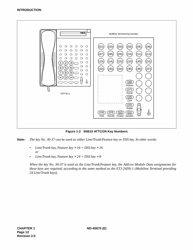
Figure 1-2 SN610 ATTCON Key Numbers
Note: The key No. 30-37 can be used as either Line/Trunk/Feature key or DSS key. In other words:
• Line/Trunk key, Feature key × 16 + DSS key × 16 or
• Line/Trunk key, Feature key × 24 + DSS key × 8
When the key No. 30-37 is used as the Line/Trunk/Feature key, the Add-on Module Data assignmthese keys are required, according to the same method as the ETJ-24DS-1 (Multiline Terminal pro24 Line/Trunk keys).
1 2 3
4 5 6
7 8 9
0 #
Speaker
(01)
Feature
Hold Transfer Answer
Redial
Conf
Recall
(06)(05)(04)(03)(02)
(12)
(31)
(37)
(07) (11)(10)(09)(08)
(13) (30)(16)(15)(14)
(32) (36)(35)(34)(33)
(18)
(17)
(19)
(20)
(21)(22)(23)(24)
DTP-32-1
Multiline Terminal Key Number
CHAPTER 1 ND-45670 (E)Page 12Revision 2.0
INTRODUCTION
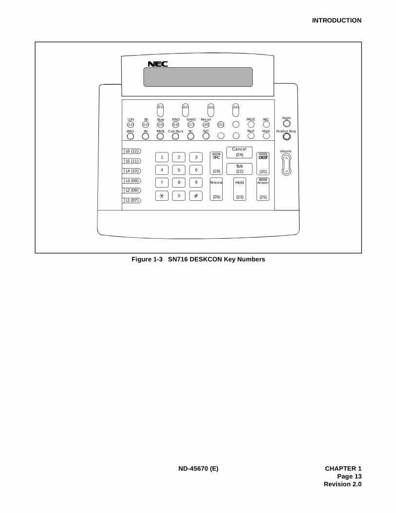
Figure 1-3 SN716 DESKCON Key Numbers
EMG BV TRKSL Call Pack SC SVC
LDN TIE Busy ATND NANS Recall(13) (14) (15) (16) (17) (18) (21)
(01) (02) (03) (04)
PAGE REC
Start Mute
Night
Position Busy
Volume
DEST
Answer
(20)
(25)
DEST
Cancel(24)
Talk(22)
Hold
(23)(26)
Release
(19)
SRC1 2 3
4 5 6
7 9
0
8
L6 (12)
L5 (11)
L4 (10)
L3 (09)
L2 (08)
L1 (07)
ND-45670 (E) CHAPTER 1Page 13
Revision 2.0
INTRODUCTION
Figure 1-4 DSS Console Key Numbers
00 01 02 03 04 05 06 07
08 09 10 11 12 13 14 15
16 17 18 19 20 21 22 23
24 25 26 27 28 29 30 31
32 33 35 36 37 38 39
40 41 42 43 44 45 46 47
48 49 50 51 52 53
54 55 56 57 58 59
EDW-48-2
34
CHAPTER 1 ND-45670 (E)Page 14Revision 2.0
INTRODUCTION
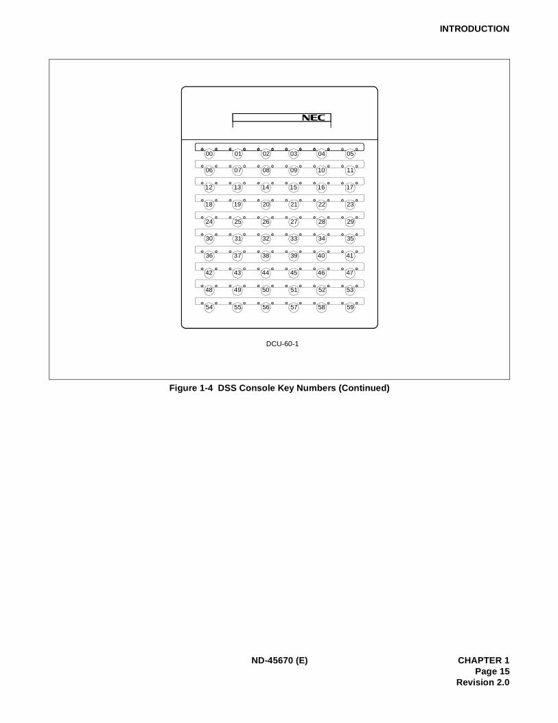
Figure 1-4 DSS Console Key Numbers (Continued)
00
06
12
18
24
30
36
42
48
54 55 56 57 58 59
49 50 51 52 53
43 44 45 46 47
37 38 39 40 41
31 32 33 34 35
25 26 27 28 29
19 20 21 22 23
13 14 15 16 17
07 08 09 10 11
01 02 03 04 05
DCU-60-1
ND-45670 (E) CHAPTER 1Page 15
Revision 2.0

INTRODUCTION
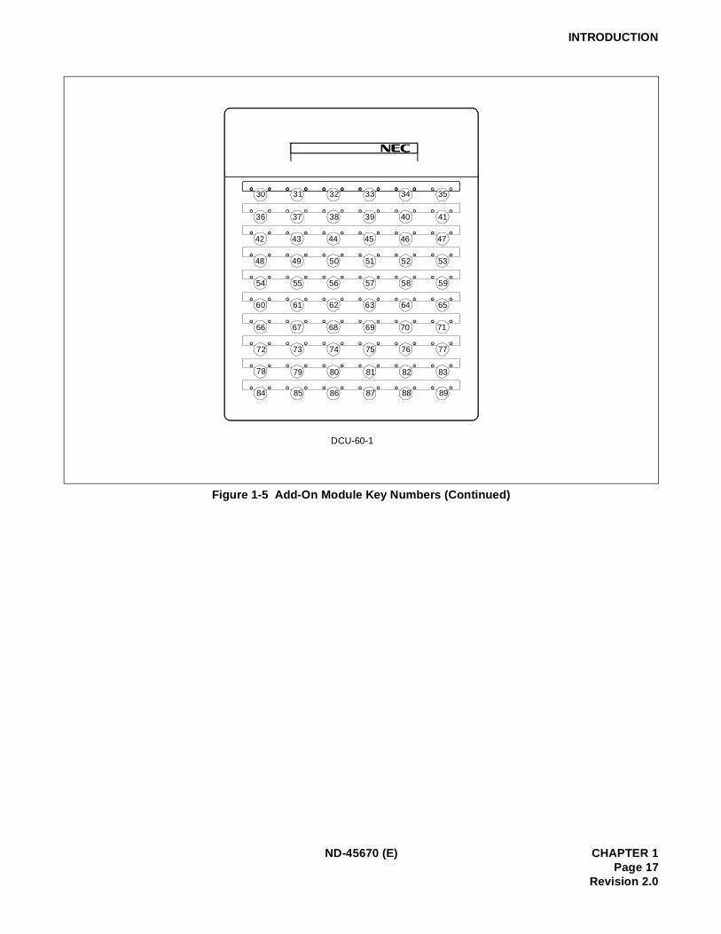
Figure 1-5 Add-On Module Key Numbers
30 31 32 33 34 35 36 37
38 39 40 41 42 43 44 45
46 47 48 49 50 51 52 53
54 55 56 57 58 59 60 61
62 63 64 65 66 67 68 69
70 71 72 73 74 75 76 77
78 79 80 81 82 83
84 85 86 87 88 89
EDW-48-2
CHAPTER 1 ND-45670 (E)Page 16Revision 2.0
INTRODUCTION
Figure 1-5 Add-On Module Key Numbers (Continued)
30
36
42
48
54
60
66
72
78
84 85 86 87 88 89
79 80 81 82 83
73 74 75 76 77
67 68 69 70 71
61 62 63 64 65
55 56 57 58 59
49 50 51 52 53
43 44 45 46 47
37 38 39 40 41
31 32 33 34 35
DCU-60-1
ND-45670 (E) CHAPTER 1Page 17
Revision 2.0

INTRODUCTION
This page is for your notes.
CHAPTER 1 ND-45670 (E)Page 18Revision 2.0
nction-e
lly as-
,
-1), whenary Refer
TCON.N716
CHAPTER 2 FEATURE PROGRAMMING
1. GENERAL
This section provides the description for programming each service feature.
2. DESCRIPTION OF SERVICE FEATURES
The description of each service feature comprises the following items:
• PROGRAMMING
This section provides the procedures for programming the service feature. If the service feature is fuing in conjunction with other features, refer to the sections containing the information pertaining to thosfeatures.
In the programming procedure, the meaning of (1), (2), and the icons are as follows:
(1) : 1st Data
(2) : 2nd Data
: Initial Data
With the system data clear command (CM00, CM01), the data with this marking ( ) is automaticasigned for each command.
: System Initialization: After entering the data, system reset is required (press SW1 on the MP card).
• HARDWARE REQUIRED
In this section, any hardware required for the feature (such as an interface card or external drive) is listedwith the exception of the following:
(a) Single-line telephone set and interface card (PN-4LC)
(b) Central Office Trunk Card (PN-4COT)
Note: For Series E Multiline Terminals (DTP-8-1, DTP-8D-1, DTP-16-1, DTP-16D-1, DTP-32-1, DTP-32Dthe feature programming is available in same method as the Series III Multiline Terminal. However,the Series E Multiline Terminal with Series III mode or the Elite Terminal is accommodated, it is necessto specify the kind of the terminal accommodated in a DLC card by programming of CM12 Y= 17.to “Proprietary Multiline Terminal” for the programming of CM12 YY = 17.
The feature programming for SN716 DESKCON is available in same method as the SN610 ATHowever, it is necessary to specify the type of console by programming of CM60 YY=22. Refer to “SDESKCON” for programming related to SN716 DESKCON.
INITIAL
ND-45670 (E) CHAPTER 2Page 19
Revision 2.0
ACCOUNT CODE
2.1 Business Features
PROGRAMMING
HARDWARE REQUIRED
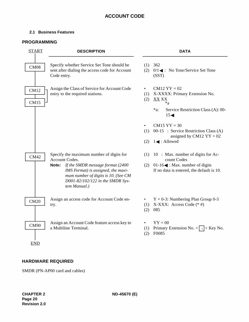
SMDR (PN-AP00 card and cables)
DESCRIPTION DATA
Specify whether Service Set Tone should be sent after dialing the access code for Account Code entry.
(1) 362(2) 0/1 : No Tone/Service Set Tone
(SST)
Assign the Class of Service for Account Code entry to the required stations.
• CM12 YY = 02(1) X-XXXX: Primary Extension No.(2) XX XX
*a: Service Restriction Class (A): 00-15
• CM15 YY = 30 (1) 00-15 : Service Restriction Class (A)
assigned by CM12 YY = 02(2) 1 : Allowed
Specify the maximum number of digits for Account Codes. Note : If the SMDR message format (2400
IMS Format) is assigned, the maxi-mum number of digits is 10. (See CM D001-82/102/122 in the SMDR Sys-tem Manual.)
(1) 10 : Max. number of digits for Ac-count Codes
(2) 01-16 : Max. number of digitsIf no data is entered, the default is 10.
Assign an access code for Account Code en-try.
• Y = 0-3: Numbering Plan Group 0-3(1) X-XXX: Access Code (* #) (2) 085
Assign an Account Code feature access key to a Multiline Terminal.
• YY = 00(1) Primary Extension No. + + Key No. (2) F0085
CM08
START
END
CM42
CM20
CM90
CM12
CM15 *a
,
CHAPTER 2 ND-45670 (E)Page 20Revision 2.0
ADD-ON MODULE (1200 Series Enhancement)
PROGRAMMING
DESCRIPTION DATA
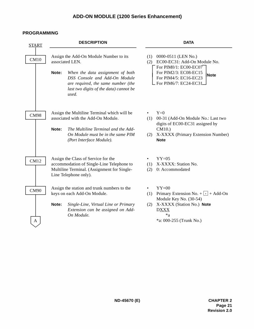
Assign the Add-On Module Number to its associated LEN.
Note: When the data assignment of bothDSS Console and Add-On Moduleare required, the same number (thelast two digits of the data) cannot beused.
(1) 0000-0511 (LEN No.)(2) EC00-EC31: Add-On Module No.
For PIM0/1: EC00-EC07 For PIM2/3: EC08-EC15 For PIM4/5: EC16-EC23 For PIM6/7: EC24-EC31
Assign the Multiline Terminal which will be associated with the Add-On Module.
Note: The Multiline Terminal and the Add-On Module must be in the same PIM(Port Interface Module).
• Y=0(1) 00-31 (Add-On Module No.: Last two
digits of EC00-EC31 assigned by CM10.)
(2) X-XXXX (Primary Extension Number)Note
Assign the Class of Service for the accommodation of Single-Line Telephone to Multiline Terminal. (Assignment for Single-Line Telephone only).
• YY=05(1) X-XXXX: Station No.(2) 0: Accommodated
Assign the station and trunk numbers to the keys on each Add-On Module.
Note: Single-Line, Virtual Line or PrimaryExtension can be assigned on Add-On Module.
• YY=00(1) Primary Extension No. + + Add-On
Module Key No. (30-54)(2) X-XXXX (Station No.) Note
DXXX*a
*a: 000-255 (Trunk No.)
START
CM10
A
CM12
CM90
CM98
Note
,
ND-45670 (E) CHAPTER 2Page 21
Revision 2.0
ADD-ON MODULE (1200 Series Enhancement)
PROGRAMMING
DESCRIPTION DATA
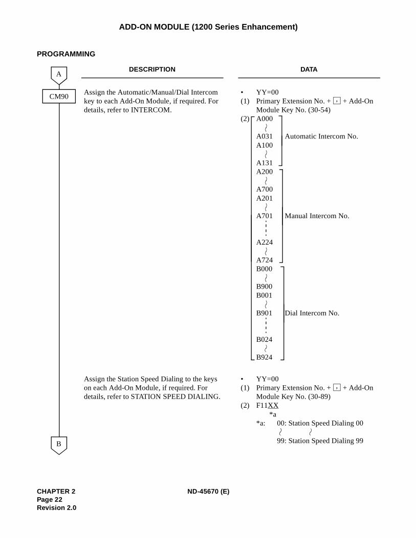
Assign the Automatic/Manual/Dial Intercom key to each Add-On Module, if required. For details, refer to INTERCOM.
• YY=00(1) Primary Extension No. + + Add-On
Module Key No. (30-54)(2) A000
A031 Automatic Intercom No.A100
A131A200
A700A201
A701 Manual Intercom No.
A224
A724B000
B900B001
B901 Dial Intercom No.
B024
B924
Assign the Station Speed Dialing to the keys on each Add-On Module, if required. For details, refer to STATION SPEED DIALING.
• YY=00(1) Primary Extension No. + + Add-On
Module Key No. (30-89)(2) F11XX
*a*a: 00: Station Speed Dialing 00
99: Station Speed Dialing 99
CM90
A
B
,
,
CHAPTER 2 ND-45670 (E)Page 22Revision 2.0
ADD-ON MODULE (1200 Series Enhancement)
HARDWARE REQUIRED
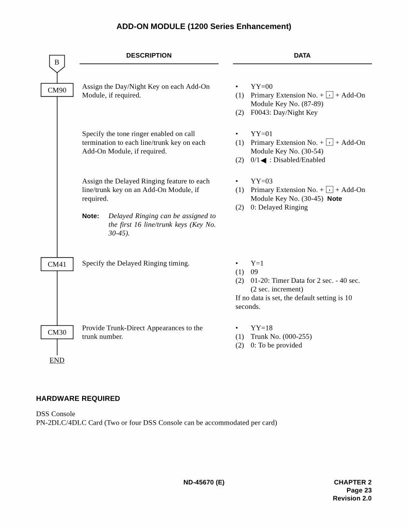
DSS ConsolePN-2DLC/4DLC Card (Two or four DSS Console can be accommodated per card)
DESCRIPTION DATA
Assign the Day/Night Key on each Add-On Module, if required.
• YY=00(1) Primary Extension No. + + Add-On
Module Key No. (87-89)(2) F0043: Day/Night Key
Specify the tone ringer enabled on call termination to each line/trunk key on each Add-On Module, if required.
• YY=01(1) Primary Extension No. + + Add-On
Module Key No. (30-54)(2) 0/1 : Disabled/Enabled
Assign the Delayed Ringing feature to each line/trunk key on an Add-On Module, if required.
Note: Delayed Ringing can be assigned tothe first 16 line/trunk keys (Key No.30-45).
• YY=03(1) Primary Extension No. + + Add-On
Module Key No. (30-45)Note(2) 0: Delayed Ringing
Specify the Delayed Ringing timing. • Y=1(1) 09(2) 01-20: Timer Data for 2 sec. - 40 sec.
(2 sec. increment)If no data is set, the default setting is 10 seconds.
Provide Trunk-Direct Appearances to the trunk number.
• YY=18(1) Trunk No. (000-255)(2) 0: To be provided
CM90
B
END
CM41
CM30
,
,
,
ND-45670 (E) CHAPTER 2Page 23
Revision 2.0
ALPHANUMERIC DISPLAY
PROGRAMMING
DESCRIPTION DATA
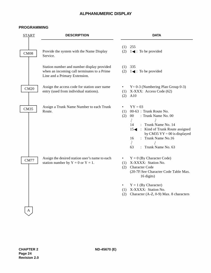
Provide the system with the Name Display Service.
(1) 255 (2) 1 : To be provided
Station number and number display provided when an incoming call terminates to a Prime Line and a Primary Extension.
(1) 335 (2) 1 : To be provided
Assign the access code for station user name entry (used from individual stations).
• Y= 0-3 (Numbering Plan Group 0-3) (1) X-XXX: Access Code (62)(2) A10
Assign a Trunk Name Number to each Trunk Route.
• YY = 03(1) 00-63 : Trunk Route No.(2) 00 : Trunk Name No. 00
14 : Trunk Name No. 1415 : Kind of Trunk Route assigned
by CM35 YY = 00 is displayed 16 : Trunk Name No.16
63 : Trunk Name No. 63
Assign the desired station user’s name to each station number by Y = 0 or Y = 1.
• Y = 0 (By Character Code)(1) X-XXXX: Station No. (2) Character Code
(20-7F:See Character Code Table Max.16 digits)
• Y = 1 (By Character) (1) X-XXXX: Station No. (2) Character (A-Z, 0-9) Max. 8 characters
CM08
CM20
START
A
CM35
CM77
CHAPTER 2 ND-45670 (E)Page 24Revision 2.0
aximumrminalltiline
e trunkbe used
name,
8
ALPHANUMERIC DISPLAY
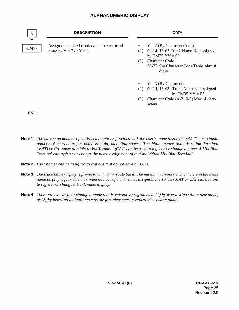
Note 1: The maximum number of stations that can be provided with the user’s name display is 384. The mnumber of characters per name is eight, including spaces. The Maintenance Administration Te(MAT) or Customer Administration Terminal (CAT) can be used to register or change a name. A MuTerminal can register or change the name assignment of that individual Multiline Terminal.
Note 2: User names can be assigned to stations that do not have an LCD.
Note 3: The trunk name display is provided on a trunk-route basis. The maximum amount of characters in thname display is four. The maximum number of trunk routes assignable is 16. The MAT or CAT can to register or change a trunk name display.
Note 4: There are two ways to change a name that is currently programmed. (1) by overwriting with a newor (2) by inserting a blank space as the first character to cancel the existing name.
DESCRIPTION DATA
Assign the desired trunk name to each trunk route by Y = 2 or Y = 3.
• Y = 2 (By Character Code)(1) 00-14, 16-63:Trunk Name No. assigned
by CM35 YY = 03. (2) Character Code
20-7F:See Character Code Table Max. digits
• Y = 3 (By Character) (1) 00-14, 16-63: Trunk Name No. assigned
by CM35 YY = 03. (2) Character Code (A-Z, 0-9) Max. 4 char-
acters
END
CM77
A
ND-45670 (E) CHAPTER 2Page 25
Revision 2.0
ALPHANUMERIC DISPLAY
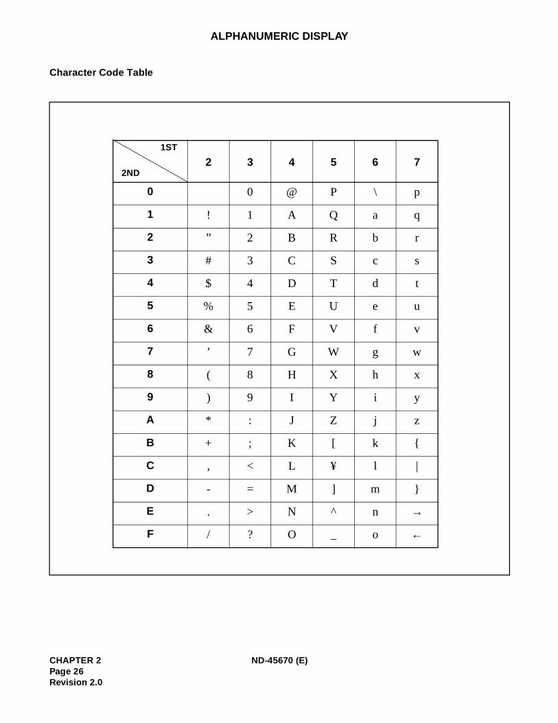
Character Code Table
2 3 4 5 6 7
0 0 @ P \ p
1 ! 1 A Q a q
2 ” 2 B R b r
3 # 3 C S c s
4 $ 4 D T d t
5 % 5 E U e u
6 & 6 F V f v
7 ’ 7 G W g w
8 ( 8 H X h x
9 ) 9 I Y i y
A * : J Z j z
B + ; K [ k
C , < L ¥ l |
D - = M ] m
E . > N ^ n →
F / ? O _ o ←
1ST
2ND
CHAPTER 2 ND-45670 (E)Page 26Revision 2.0
ANALOG PORT ADAPTER (1200 Series Enhancement)
PROGRAMMING
To assign the Single Port Mode:
To assign the Dual Port Mode:
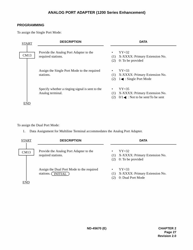
1. Data Assignment for Multiline Terminal accommodates the Analog Port Adapter.
DESCRIPTION DATA
Provide the Analog Port Adapter to the required stations.
• YY=32(1) X-XXXX: Primary Extension No.(2) 0: To be provided
Assign the Single Port Mode to the required stations.
• YY=33(1) X-XXXX: Primary Extension No.(2) 1 : Single Port Mode
Specify whether a ringing signal is sent to the Analog terminal.
• YY=35(1) X-XXXX: Primary Extension No.(2) 0/1 : Not to be sent/To be sent
DESCRIPTION DATA
Provide the Analog Port Adapter to the required stations.
• YY=32(1) X-XXXX: Primary Extension No.(2) 0: To be provided
Assign the Dual Port Mode to the required stations.
• YY=33(1) X-XXXX: Primary Extension No.(2) 0: Dual Port Mode
START
CM13
END
START
CM13
END
INITIAL
ND-45670 (E) CHAPTER 2Page 27
Revision 2.0
ANALOG PORT ADAPTER (1200 Series Enhancement)
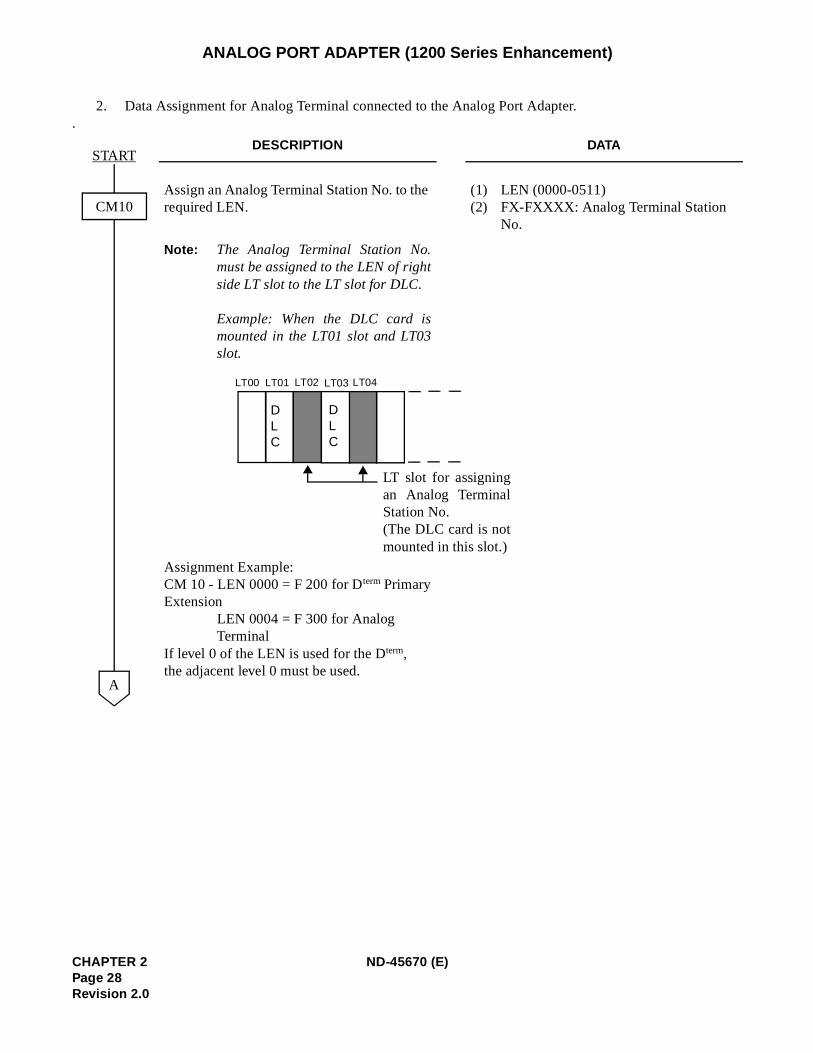
2. Data Assignment for Analog Terminal connected to the Analog Port Adapter..
DESCRIPTION DATA
Assign an Analog Terminal Station No. to the required LEN.
(1) LEN (0000-0511)(2) FX-FXXXX: Analog Terminal Station
No.
Note: The Analog Terminal Station No.must be assigned to the LEN of rightside LT slot to the LT slot for DLC.
Example: When the DLC card ismounted in the LT01 slot and LT03slot.
Assignment Example:CM 10 - LEN 0000 = F 200 for Dterm PrimaryExtension
LEN 0004 = F 300 for Analog Terminal
If level 0 of the LEN is used for the Dterm, the adjacent level 0 must be used.
START
A
CM10
LT00 LT01 LT02 LT03 LT04
DLC
DLC
LT slot for assigningan Analog TerminalStation No.(The DLC card is notmounted in this slot.)
CHAPTER 2 ND-45670 (E)Page 28Revision 2.0
ANALOG PORT ADAPTER (1200 Series Enhancement)
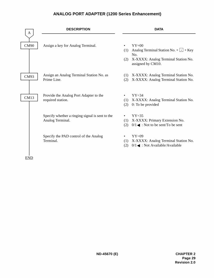
DESCRIPTION DATA
Assign a key for Analog Terminal. • YY=00(1) Analog Terminal Station No. + + Key
No.(2) X-XXXX: Analog Terminal Station No.
assigned by CM10.
Assign an Analog Terminal Station No. as Prime Line.
(1) X-XXXX: Analog Terminal Station No.(2) X-XXXX: Analog Terminal Station No.
Provide the Analog Port Adapter to the required station.
• YY=34(1) X-XXXX: Analog Terminal Station No.(2) 0: To be provided
Specify whether a ringing signal is sent to the Analog Terminal.
• YY=35(1) X-XXXX: Primary Extension No.(2) 0/1 : Not to be sent/To be sent
Specify the PAD control of the Analog Terminal.
• YY=09(1) X-XXXX: Analog Terminal Station No.(2) 0/1 : Not Available/Available
CM90
CM93
CM13
END
A
,
ND-45670 (E) CHAPTER 2Page 29
Revision 2.0
ANNOUNCEMENT SERVICE
PROGRAMMING
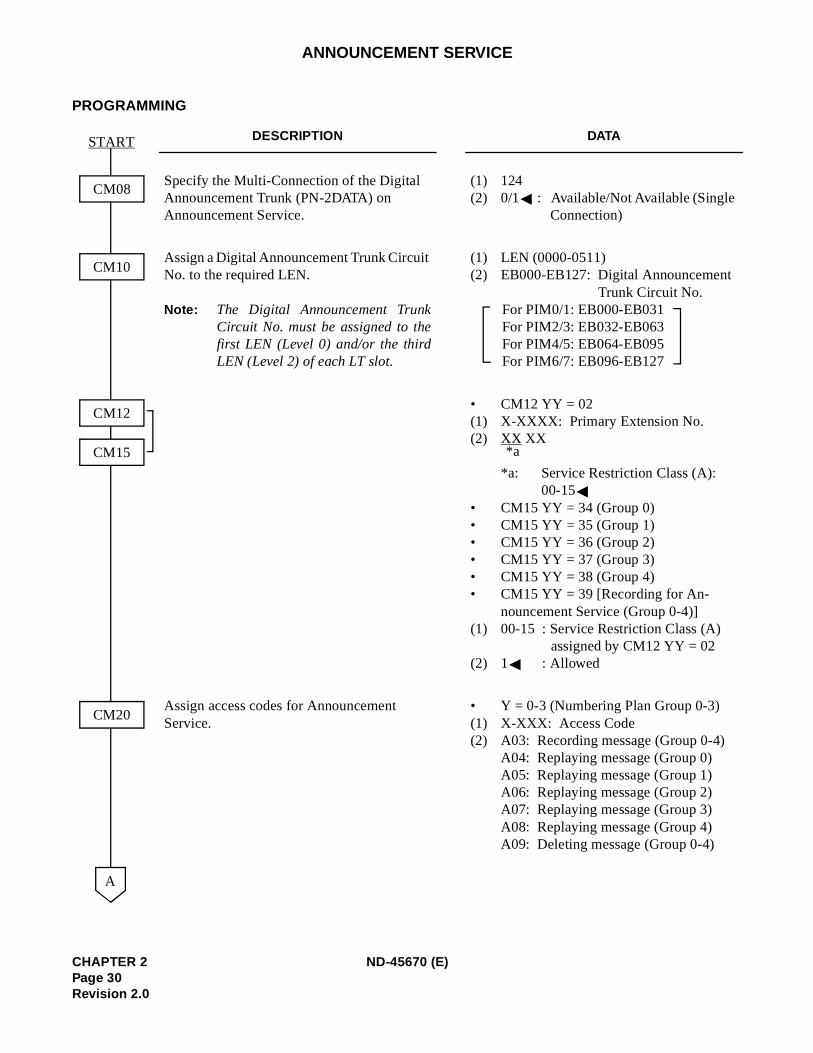
DESCRIPTION DATA
Specify the Multi-Connection of the Digital Announcement Trunk (PN-2DATA) on Announcement Service.
(1) 124 (2) 0/1 : Available/Not Available (Single
Connection)
Assign a Digital Announcement Trunk Circuit No. to the required LEN.
Note: The Digital Announcement TrunkCircuit No. must be assigned to thefirst LEN (Level 0) and/or the thirdLEN (Level 2) of each LT slot.
(1) LEN (0000-0511) (2) EB000-EB127: Digital Announcement
Trunk Circuit No. For PIM0/1: EB000-EB031 For PIM2/3: EB032-EB063 For PIM4/5: EB064-EB095 For PIM6/7: EB096-EB127
• CM12 YY = 02(1) X-XXXX: Primary Extension No.(2) XX XX
*a: Service Restriction Class (A): 00-15
• CM15 YY = 34 (Group 0) • CM15 YY = 35 (Group 1) • CM15 YY = 36 (Group 2) • CM15 YY = 37 (Group 3) • CM15 YY = 38 (Group 4) • CM15 YY = 39 [Recording for An-
nouncement Service (Group 0-4)] (1) 00-15 : Service Restriction Class (A)
assigned by CM12 YY = 02 (2) 1 : Allowed
Assign access codes for Announcement Service.
• Y = 0-3 (Numbering Plan Group 0-3) (1) X-XXX: Access Code (2) A03: Recording message (Group 0-4)
A04: Replaying message (Group 0)A05: Replaying message (Group 1)A06: Replaying message (Group 2) A07: Replaying message (Group 3)A08: Replaying message (Group 4)A09: Deleting message (Group 0-4)
CM08
CM10
START
A
CM20
CM12
CM15 *a
CHAPTER 2 ND-45670 (E)Page 30Revision 2.0
cement Digital
peated
ent is
nce-
ANNOUNCEMENT SERVICE
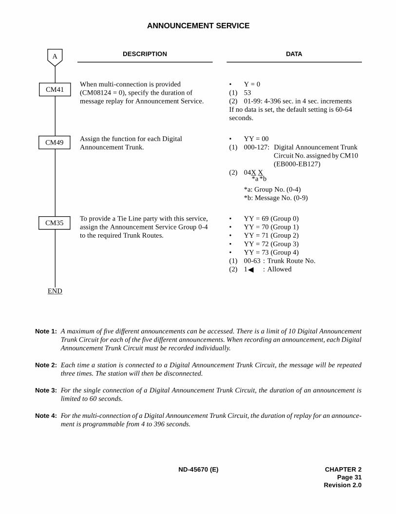
Note 1: A maximum of five different announcements can be accessed. There is a limit of 10 Digital AnnounTrunk Circuit for each of the five different announcements. When recording an announcement, eachAnnouncement Trunk Circuit must be recorded individually.
Note 2: Each time a station is connected to a Digital Announcement Trunk Circuit, the message will be rethree times. The station will then be disconnected.
Note 3: For the single connection of a Digital Announcement Trunk Circuit, the duration of an announcemlimited to 60 seconds.
Note 4: For the multi-connection of a Digital Announcement Trunk Circuit, the duration of replay for an annoument is programmable from 4 to 396 seconds.
DESCRIPTION DATA
When multi-connection is provided (CM08124 = 0), specify the duration of message replay for Announcement Service.
• Y = 0 (1) 53(2) 01-99: 4-396 sec. in 4 sec. increments If no data is set, the default setting is 60-64 seconds.
Assign the function for each Digital Announcement Trunk.
• YY = 00(1) 000-127: Digital Announcement Trunk
Circuit No. assigned by CM10 (EB000-EB127)
(2) 04X X
*a: Group No. (0-4)*b: Message No. (0-9)
To provide a Tie Line party with this service, assign the Announcement Service Group 0-4 to the required Trunk Routes.
• YY = 69 (Group 0)• YY = 70 (Group 1)• YY = 71 (Group 2)• YY = 72 (Group 3)• YY = 73 (Group 4)(1) 00-63 : Trunk Route No.(2) 1 : Allowed
END
CM41
A
CM49
CM35
*b*a
ND-45670 (E) CHAPTER 2Page 31
Revision 2.0
a busy or
ANNOUNCEMENT SERVICE
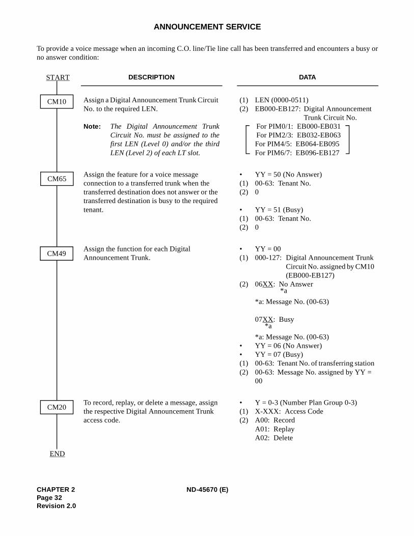
To provide a voice message when an incoming C.O. line/Tie line call has been transferred and encounters no answer condition:
DESCRIPTION DATA
Assign a Digital Announcement Trunk Circuit No. to the required LEN.
Note: The Digital Announcement TrunkCircuit No. must be assigned to thefirst LEN (Level 0) and/or the thirdLEN (Level 2) of each LT slot.
(1) LEN (0000-0511) (2) EB000-EB127: Digital Announcement
Trunk Circuit No. For PIM0/1: EB000-EB031 For PIM2/3: EB032-EB063 For PIM4/5: EB064-EB095 For PIM6/7: EB096-EB127
Assign the feature for a voice message connection to a transferred trunk when the transferred destination does not answer or the transferred destination is busy to the required tenant.
• YY = 50 (No Answer)(1) 00-63: Tenant No. (2) 0
• YY = 51 (Busy) (1) 00-63: Tenant No. (2) 0
Assign the function for each Digital Announcement Trunk.
• YY = 00(1) 000-127: Digital Announcement Trunk
Circuit No. assigned by CM10 (EB000-EB127)
(2) 06XX: No Answer
*a: Message No. (00-63)
07XX: Busy
*a: Message No. (00-63)• YY = 06 (No Answer)• YY = 07 (Busy) (1) 00-63: Tenant No. of transferring station(2) 00-63: Message No. assigned by YY =
00
To record, replay, or delete a message, assign the respective Digital Announcement Trunk access code.
• Y = 0-3 (Number Plan Group 0-3) (1) X-XXX: Access Code (2) A00: Record
A01: Replay A02: Delete
CM10
START
END
CM65
CM49
CM20
*a
*a
CHAPTER 2 ND-45670 (E)Page 32Revision 2.0

line callen, nor-
t Trunk
busy
.
repro-
ANNOUNCEMENT SERVICE
Note 5: Announcement Service can be used to provide a voice message when an incoming C.O. line/Tiehas been transferred and encounters a busy or no answer condition. After the voice message is givmal call processing continues.
- This application can be programmed on a tenant basis.
- Only one (1) message of up to 60 seconds can be recorded on an individual Digital AnnouncemenCircuit.
- In this application, a minimum of two digital announcement Trunk Circuits are needed, one forcondition, and one for no answer.
- More than one Digital Announcement Trunk Circuit can be used, depending on traffic conditions
- System programming can be set to, wait until circuit(s) become free or immediately follow pgrammed normal call handling, if a busy condition is encountered.
- Digital Announcement Trunk Circuits can be shared among tenants.
- This feature does not function on Attendant transferred calls.
ND-45670 (E) CHAPTER 2Page 33
Revision 2.0
ic On
ANNOUNCEMENT SERVICE
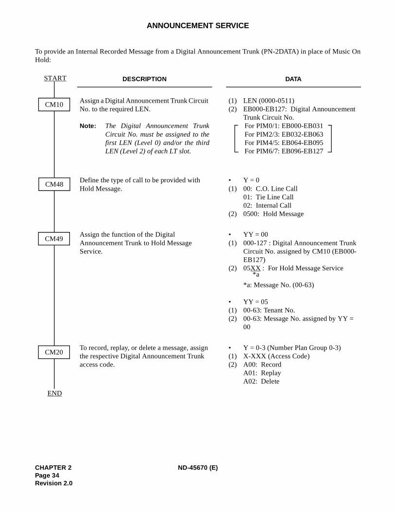
To provide an Internal Recorded Message from a Digital Announcement Trunk (PN-2DATA) in place of MusHold:
DESCRIPTION DATA
Assign a Digital Announcement Trunk Circuit No. to the required LEN.
Note: The Digital Announcement TrunkCircuit No. must be assigned to thefirst LEN (Level 0) and/or the thirdLEN (Level 2) of each LT slot.
(1) LEN (0000-0511) (2) EB000-EB127: Digital Announcement
Trunk Circuit No.For PIM0/1: EB000-EB031 For PIM2/3: EB032-EB063For PIM4/5: EB064-EB095For PIM6/7: EB096-EB127
Define the type of call to be provided with Hold Message.
• Y = 0(1) 00: C.O. Line Call
01: Tie Line Call 02: Internal Call
(2) 0500: Hold Message
Assign the function of the Digital Announcement Trunk to Hold Message Service.
• YY = 00(1) 000-127 : Digital Announcement Trunk
Circuit No. assigned by CM10 (EB000-EB127)
(2) 05XX : For Hold Message Service
*a: Message No. (00-63)
• YY = 05(1) 00-63: Tenant No. (2) 00-63: Message No. assigned by YY =
00
To record, replay, or delete a message, assign the respective Digital Announcement Trunk access code.
• Y = 0-3 (Number Plan Group 0-3)(1) X-XXX (Access Code) (2) A00: Record
A01: Replay A02: Delete
CM10
START
END
CM48
CM49
CM20
*a
CHAPTER 2 ND-45670 (E)Page 34Revision 2.0

.
ion) on
nnec-
ANNOUNCEMENT SERVICE
Note 6: A voice message in place of Music-On-Hold can be provided when a call has been placed on hold
- Different messages can be programmed on a tenant basis.
- Different messages can be programmed, depending on the type of line (CO line, Tie line or statHold.
- More than one connection can be made to a Digital Announcement Trunk Circuit. Only the first cotion can be assured of hearing the message from the beginning.
- Announcements will be repeated until the call is removed from hold.
ND-45670 (E) CHAPTER 2Page 35
Revision 2.0
ANNOUNCEMENT SERVICE
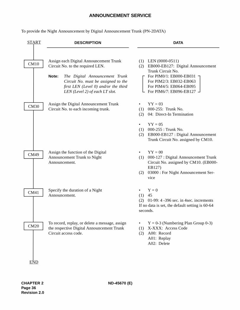
To provide the Night Announcement by Digital Announcement Trunk (PN-2DATA)
DESCRIPTION DATA
Assign each Digital Announcement Trunk Circuit No. to the required LEN.
Note: The Digital Announcement TrunkCircuit No. must be assigned to thefirst LEN (Level 0) and/or the thirdLEN (Level 2) of each LT slot.
(1) LEN (0000-0511)(2) EB000-EB127: Digital Announcement
Trunk Circuit No.For PIM0/1: EB000-EB031For PIM2/3: EB032-EB063 For PIM4/5: EB064-EB095 For PIM6/7: EB096-EB127
Assign the Digital Announcement Trunk Circuit No. to each incoming trunk.
• YY = 03(1) 000-255: Trunk No.(2) 04: Direct-In Termination
• YY = 05(1) 000-255 : Trunk No.(2) EB000-EB127 : Digital Announcement
Trunk Circuit No. assigned by CM10.
Assign the function of the Digital Announcement Trunk to Night Announcement.
• YY = 00(1) 000-127 : Digital Announcement Trunk
Circuit No. assigned by CM10. (EB000-EB127)
(2) 03000 : For Night Announcement Ser-vice
Specify the duration of a Night Announcement.
• Y = 0(1) 45(2) 01-99: 4 -396 sec. in 4sec. incrementsIf no data is set, the default setting is 60-64 seconds.
To record, replay, or delete a message, assign the respective Digital Announcement Trunk Circuit access code.
• Y = 0-3 (Numbering Plan Group 0-3) (1) X-XXX: Access Code(2) A00: Record
A01: Replay A02: Delete
CM10
START
END
CM30
CM49
CM41
CM20
CHAPTER 2 ND-45670 (E)Page 36Revision 2.0
t con-
ements.
ANNOUNCEMENT SERVICE
Note 7: A voice message can be sent to incoming C.O. lines during night mode.
- Different messages can be programmed on each C.O. line.
- The voice message can be programmed for day/night.
- More than one connection can be made to a Digital Announcement Trunk Circuit. Only the firsnection can be assured of hearing the message from the beginning.
- Announcements may be programmed to be repeated from 4 to 120 seconds in four-second incr
HARDWARE REQUIRED
Digital Announcement Trunk (PN-2DATA).
ND-45670 (E) CHAPTER 2Page 37
Revision 2.0
ANSWER KEY
PROGRAMMING
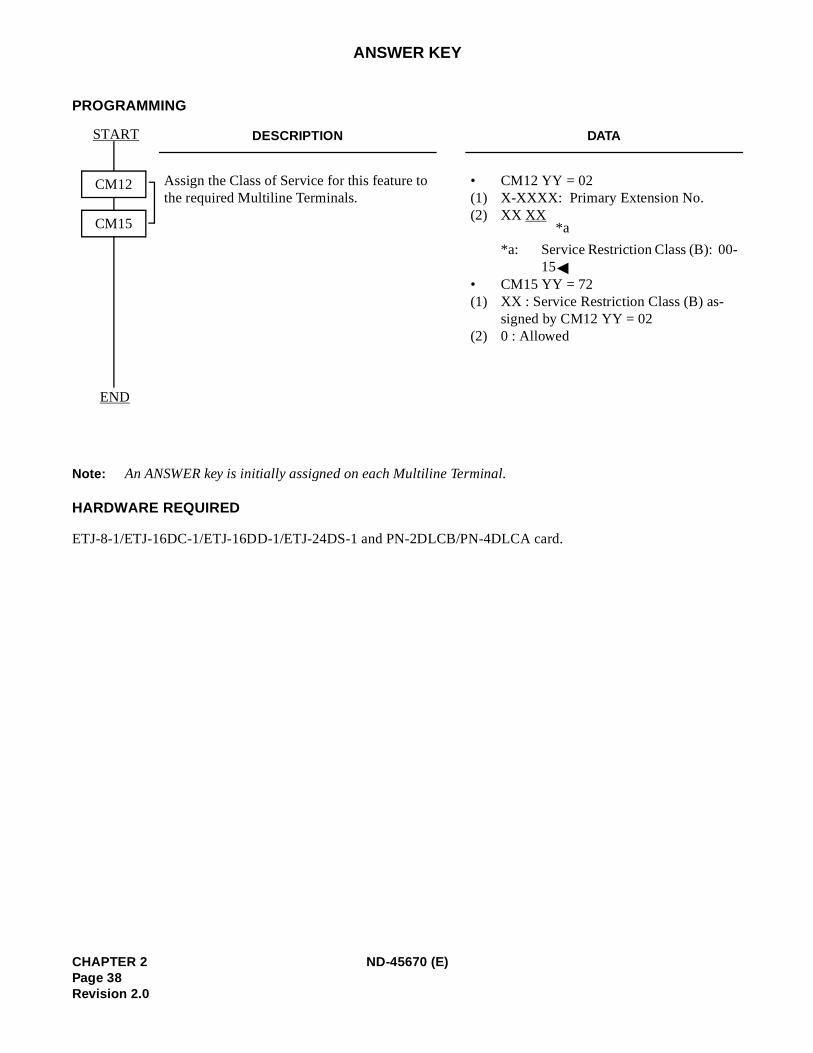
Note: An ANSWER key is initially assigned on each Multiline Terminal.
HARDWARE REQUIRED
ETJ-8-1/ETJ-16DC-1/ETJ-16DD-1/ETJ-24DS-1 and PN-2DLCB/PN-4DLCA card.
DESCRIPTION DATA
Assign the Class of Service for this feature to the required Multiline Terminals.
• CM12 YY = 02 (1) X-XXXX: Primary Extension No. (2) XX XX
*a: Service Restriction Class (B): 00-15
• CM15 YY = 72 (1) XX : Service Restriction Class (B) as-
signed by CM12 YY = 02(2) 0 : Allowed
START
END
CM12
CM15 *a
CHAPTER 2 ND-45670 (E)Page 38Revision 2.0
)
ATTENDANT-ASSISTED CALLING
PROGRAMMING
DESCRIPTION DATA
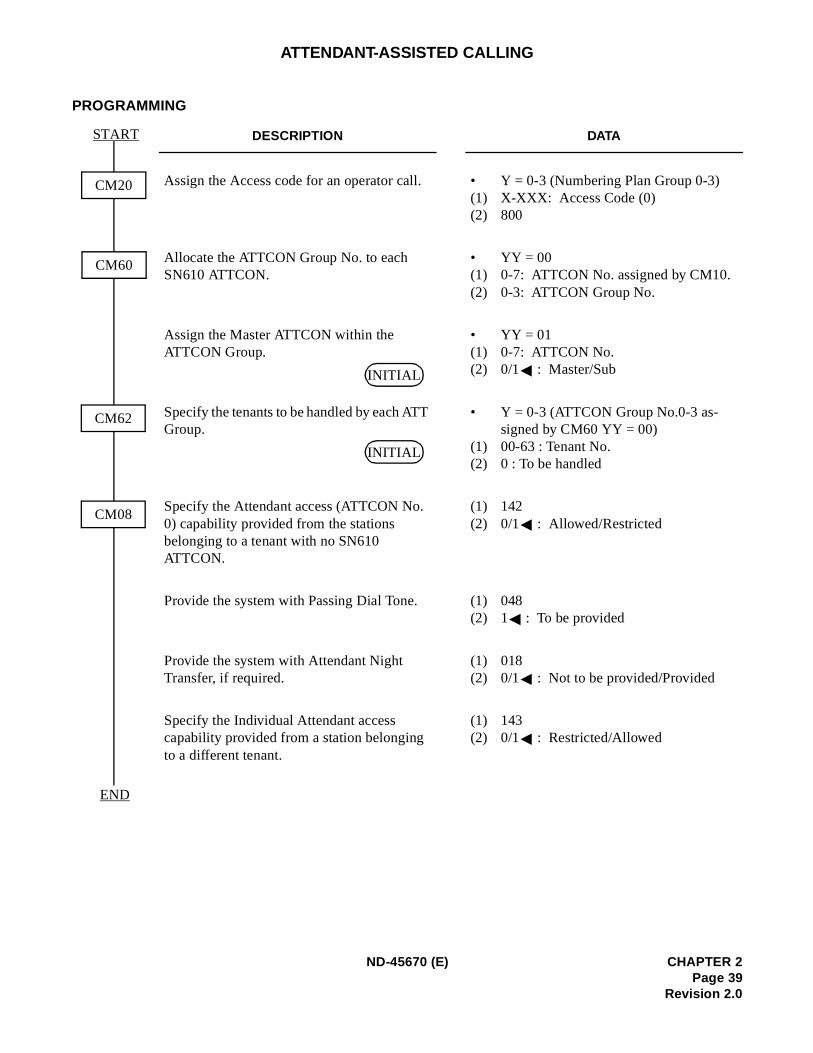
Assign the Access code for an operator call. • Y = 0-3 (Numbering Plan Group 0-3(1) X-XXX: Access Code (0) (2) 800
Allocate the ATTCON Group No. to each SN610 ATTCON.
• YY = 00(1) 0-7: ATTCON No. assigned by CM10. (2) 0-3: ATTCON Group No.
Assign the Master ATTCON within the ATTCON Group.
• YY = 01(1) 0-7: ATTCON No.(2) 0/1 : Master/Sub
Specify the tenants to be handled by each ATT Group.
• Y = 0-3 (ATTCON Group No.0-3 as-signed by CM60 YY = 00)
(1) 00-63 : Tenant No. (2) 0 : To be handled
Specify the Attendant access (ATTCON No. 0) capability provided from the stations belonging to a tenant with no SN610 ATTCON.
(1) 142 (2) 0/1 : Allowed/Restricted
Provide the system with Passing Dial Tone. (1) 048 (2) 1 : To be provided
Provide the system with Attendant Night Transfer, if required.
(1) 018 (2) 0/1 : Not to be provided/Provided
Specify the Individual Attendant access capability provided from a station belonging to a different tenant.
(1) 143 (2) 0/1 : Restricted/Allowed
CM20
START
END
CM60
CM62
CM08
INITIAL
INITIAL
ND-45670 (E) CHAPTER 2Page 39
Revision 2.0
nk by de-
.
6
ATTENDANT CAMP-ON
PROGRAMMING
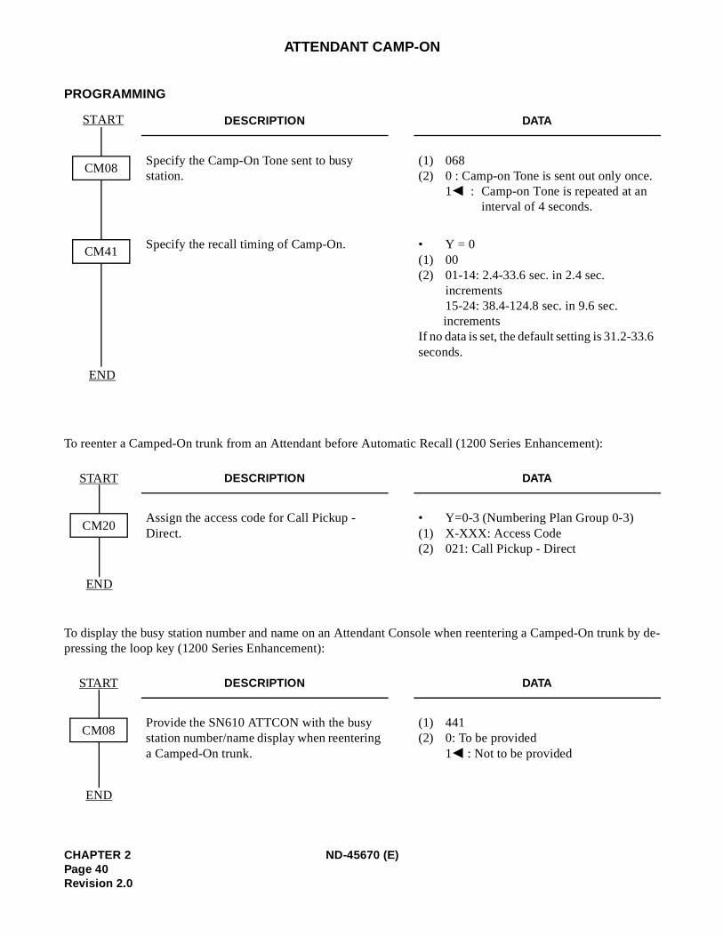
To reenter a Camped-On trunk from an Attendant before Automatic Recall (1200 Series Enhancement):
To display the busy station number and name on an Attendant Console when reentering a Camped-On trupressing the loop key (1200 Series Enhancement):
DESCRIPTION DATA
Specify the Camp-On Tone sent to busy station.
(1) 068 (2) 0 : Camp-on Tone is sent out only once
1 : Camp-on Tone is repeated at an interval of 4 seconds.
Specify the recall timing of Camp-On. • Y = 0 (1) 00(2) 01-14: 2.4-33.6 sec. in 2.4 sec.
increments15-24: 38.4-124.8 sec. in 9.6 sec. increments
If no data is set, the default setting is 31.2-33.seconds.
DESCRIPTION DATA
Assign the access code for Call Pickup - Direct.
• Y=0-3 (Numbering Plan Group 0-3)(1) X-XXX: Access Code(2) 021: Call Pickup - Direct
DESCRIPTION DATA
Provide the SN610 ATTCON with the busy station number/name display when reentering a Camped-On trunk.
(1) 441(2) 0: To be provided
1 : Not to be provided
START
END
CM08
CM41
START
END
CM20
START
END
CM08
CHAPTER 2 ND-45670 (E)Page 40Revision 2.0
ATTENDANT CONSOLE (SN610 ATTCON)
PROGRAMMING
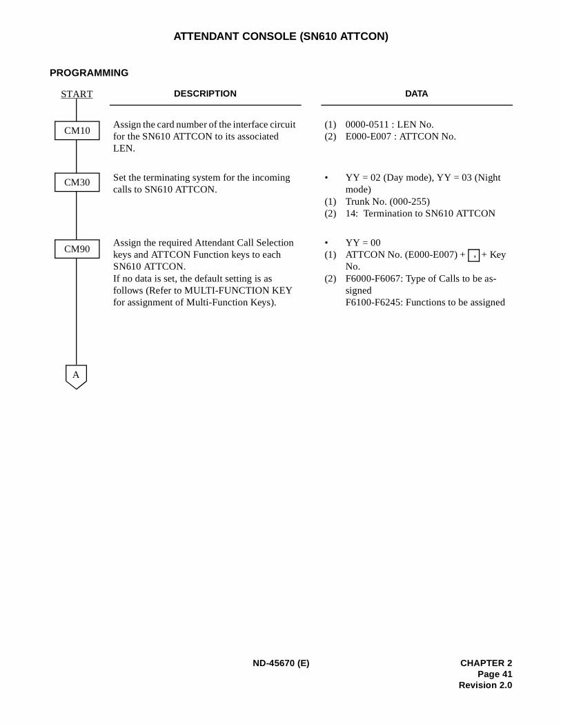
DESCRIPTION DATA
Assign the card number of the interface circuit for the SN610 ATTCON to its associated LEN.
(1) 0000-0511 : LEN No.(2) E000-E007 : ATTCON No.
Set the terminating system for the incoming calls to SN610 ATTCON.
• YY = 02 (Day mode), YY = 03 (Night mode)
(1) Trunk No. (000-255)(2) 14: Termination to SN610 ATTCON
Assign the required Attendant Call Selection keys and ATTCON Function keys to each SN610 ATTCON.If no data is set, the default setting is as follows (Refer to MULTI-FUNCTION KEY for assignment of Multi-Function Keys).
• YY = 00(1) ATTCON No. (E000-E007) + + Key
No. (2) F6000-F6067: Type of Calls to be as-
signedF6100-F6245: Functions to be assigned
CM10
CM30
START
A
CM90 ,
ND-45670 (E) CHAPTER 2Page 41
Revision 2.0
on
d
ATTENDANT CONSOLE (SN610 ATTCON)
DESCRIPTION DATA
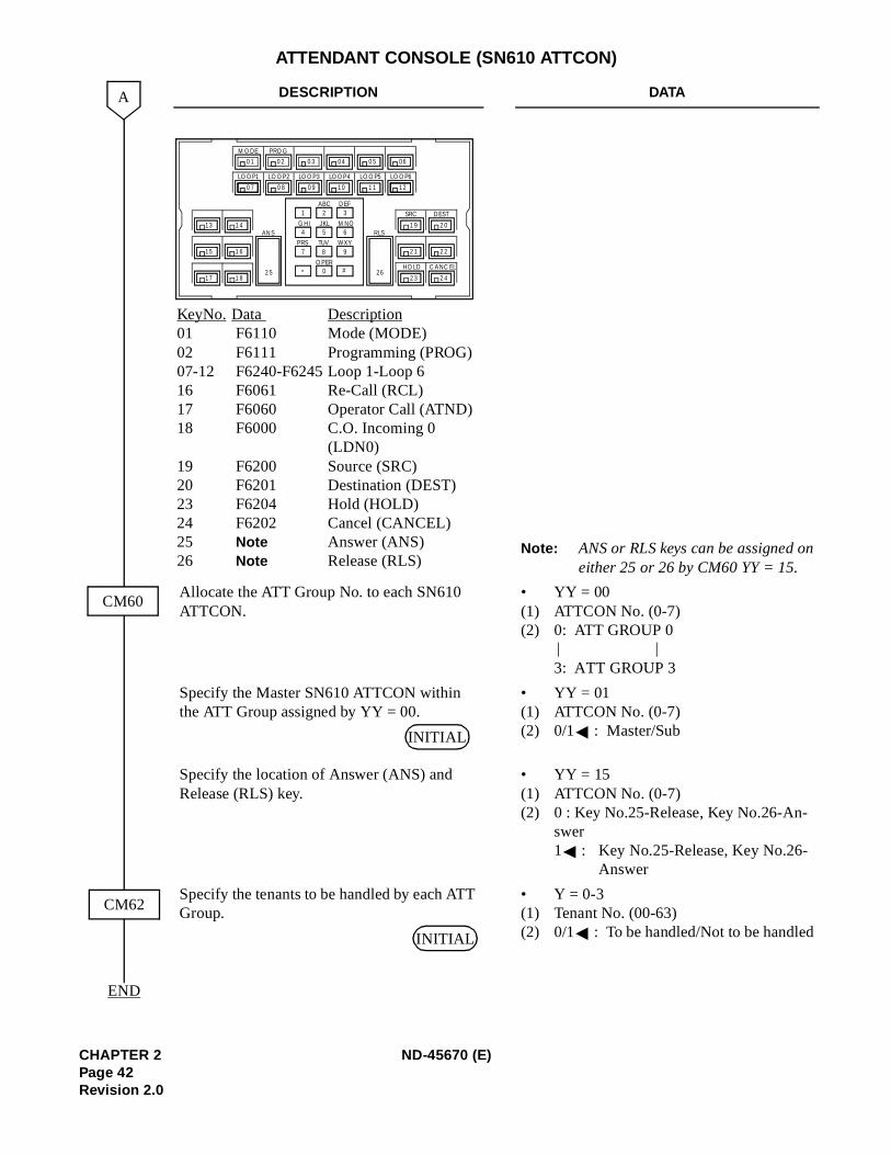
Note: ANS or RLS keys can be assigned either 25 or 26 by CM60 YY = 15.
Allocate the ATT Group No. to each SN610 ATTCON.
• YY = 00(1) ATTCON No. (0-7)(2) 0: ATT GROUP 0
3: ATT GROUP 3
Specify the Master SN610 ATTCON within the ATT Group assigned by YY = 00.
• YY = 01(1) ATTCON No. (0-7) (2) 0/1 : Master/Sub
Specify the location of Answer (ANS) and Release (RLS) key.
• YY = 15(1) ATTCON No. (0-7)(2) 0 : Key No.25-Release, Key No.26-An-
swer1 : Key No.25-Release, Key No.26-
Answer
Specify the tenants to be handled by each ATT Group.
• Y = 0-3(1) Tenant No. (00-63)(2) 0/1 : To be handled/Not to be handle
END
A
CM62
CM60
Key No. Data Description 01 F6110 Mode (MODE)02 F6111 Programming (PROG) 07-12 F6240-F6245 Loop 1-Loop 6 16 F6061 Re-Call (RCL)17 F6060 Operator Call (ATND)18 F6000 C.O. Incoming 0
(LDN0)19 F6200 Source (SRC)20 F6201 Destination (DEST) 23 F6204 Hold (HOLD)24 F6202 Cancel (CANCEL) 25 Note Answer (ANS) 26 Note Release (RLS)
LOOP1 LOOP2 LOOP3 LOOP4 LOOP5 LOOP6
0 1
ANS
2 5
R LS
26
1 2 3
4 5 6
7 8 9
* 0 #
SRC DEST
HOLD CANC EL
M ODE PROG
13 1 4
15 1 6
17 1 8
1 9 2 0
2 1 2 2
2 3 2 4
0 7
0 2 0 3 04 0 5 06
0 8 0 9 10 1 1 12
ABC DEF
JKL M NOGHI
TUV WX YPRS
OPER
| |
INITIAL
INITIAL
CHAPTER 2 ND-45670 (E)Page 42Revision 2.0
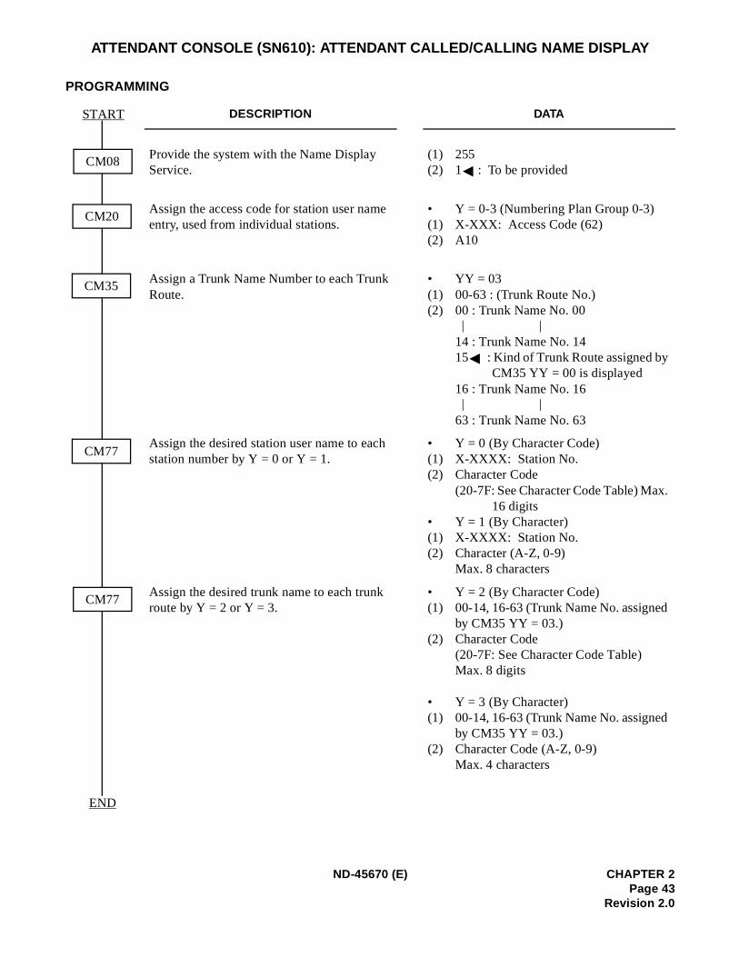
.
ATTENDANT CONSOLE (SN610): ATTENDANT CALLED/CALLING NAME DISPLAY
PROGRAMMING
DESCRIPTION DATA
Provide the system with the Name Display Service.
(1) 255 (2) 1 : To be provided
Assign the access code for station user name entry, used from individual stations.
• Y = 0-3 (Numbering Plan Group 0-3) (1) X-XXX: Access Code (62) (2) A10
Assign a Trunk Name Number to each Trunk Route.
• YY = 03(1) 00-63 : (Trunk Route No.) (2) 00 : Trunk Name No. 00
14 : Trunk Name No. 14 15 : Kind of Trunk Route assigned by
CM35 YY = 00 is displayed 16 : Trunk Name No. 16
63 : Trunk Name No. 63
Assign the desired station user name to each station number by Y = 0 or Y = 1.
• Y = 0 (By Character Code)(1) X-XXXX: Station No. (2) Character Code
(20-7F: See Character Code Table) Max16 digits
• Y = 1 (By Character) (1) X-XXXX: Station No. (2) Character (A-Z, 0-9)
Max. 8 characters
Assign the desired trunk name to each trunk route by Y = 2 or Y = 3.
• Y = 2 (By Character Code)(1) 00-14, 16-63 (Trunk Name No. assigned
by CM35 YY = 03.)(2) Character Code
(20-7F: See Character Code Table) Max. 8 digits
• Y = 3 (By Character) (1) 00-14, 16-63 (Trunk Name No. assigned
by CM35 YY = 03.)(2) Character Code (A-Z, 0-9)
Max. 4 characters
START
END
CM20
CM35
CM77
CM08
CM77
| |
| |
ND-45670 (E) CHAPTER 2Page 43
Revision 2.0
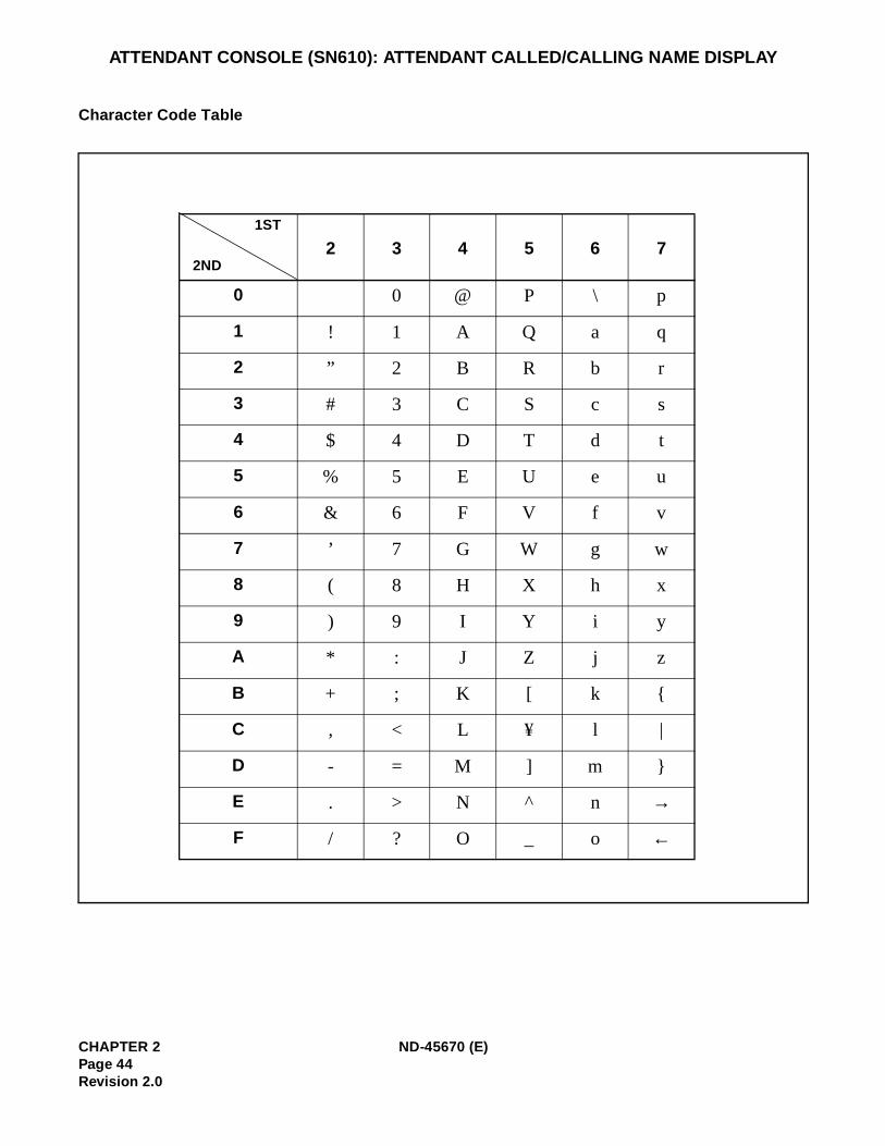
ATTENDANT CONSOLE (SN610): ATTENDANT CALLED/CALLING NAME DISPLAY
Character Code Table
2 3 4 5 6 7
0 0 @ P \ p
1 ! 1 A Q a q
2 ” 2 B R b r
3 # 3 C S c s
4 $ 4 D T d t
5 % 5 E U e u
6 & 6 F V f v
7 ’ 7 G W g w
8 ( 8 H X h x
9 ) 9 I Y i y
A * : J Z j z
B + ; K [ k
C , < L ¥ l |
D - = M ] m
E . > N ^ n →
F / ? O _ o ←
1ST
2ND
CHAPTER 2 ND-45670 (E)Page 44Revision 2.0
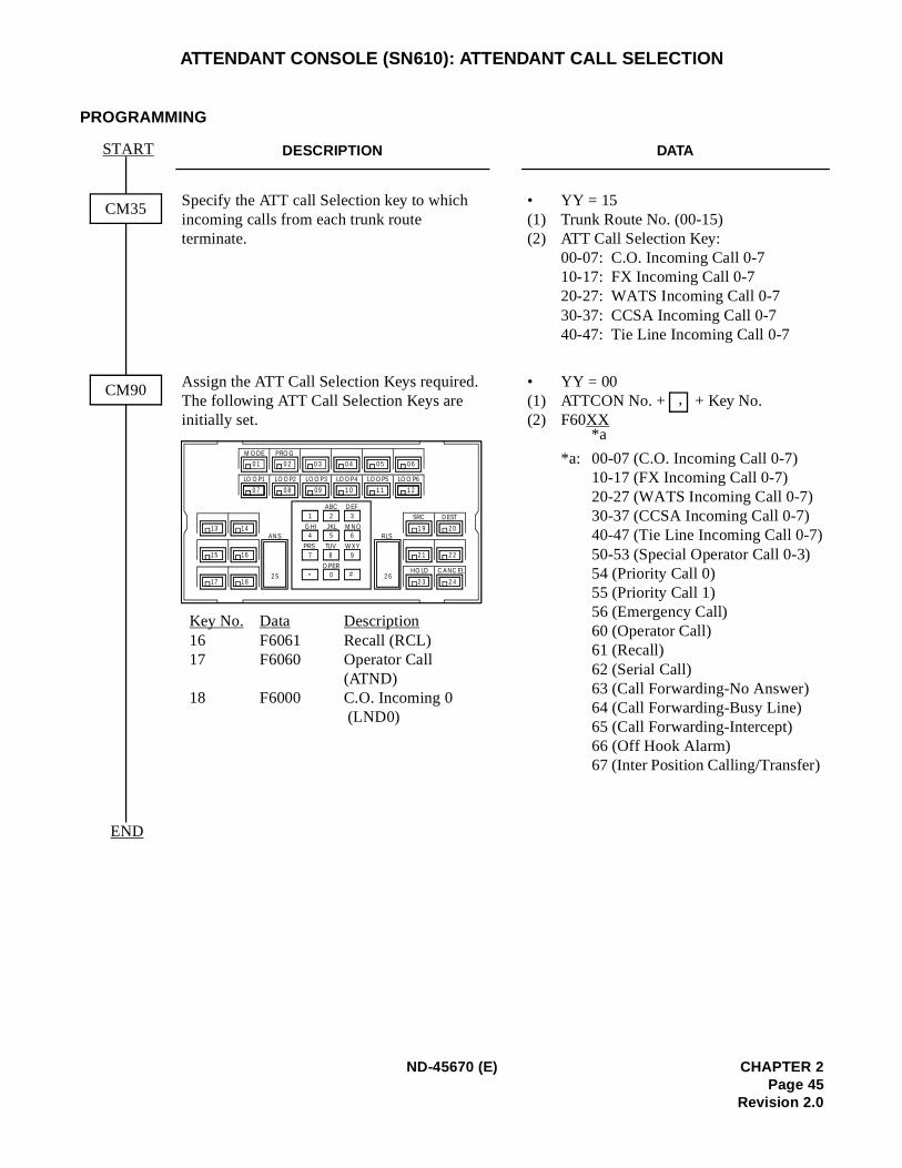
ATTENDANT CONSOLE (SN610): ATTENDANT CALL SELECTION
PROGRAMMING
DESCRIPTION DATA
Specify the ATT call Selection key to which incoming calls from each trunk route terminate.
• YY = 15(1) Trunk Route No. (00-15) (2) ATT Call Selection Key:
00-07: C.O. Incoming Call 0-7 10-17: FX Incoming Call 0-7 20-27: WATS Incoming Call 0-7 30-37: CCSA Incoming Call 0-7 40-47: Tie Line Incoming Call 0-7
Assign the ATT Call Selection Keys required. The following ATT Call Selection Keys are initially set.
• YY = 00(1) ATTCON No. + + Key No.(2) F60XX
*a: 00-07 (C.O. Incoming Call 0-7) 10-17 (FX Incoming Call 0-7)20-27 (WATS Incoming Call 0-7) 30-37 (CCSA Incoming Call 0-7) 40-47 (Tie Line Incoming Call 0-7)50-53 (Special Operator Call 0-3)54 (Priority Call 0) 55 (Priority Call 1) 56 (Emergency Call) 60 (Operator Call) 61 (Recall)62 (Serial Call) 63 (Call Forwarding-No Answer) 64 (Call Forwarding-Busy Line)65 (Call Forwarding-Intercept) 66 (Off Hook Alarm)67 (Inter Position Calling/Transfer)
START
END
CM35
CM90
Key No. Data Description16 F6061 Recall (RCL) 17 F6060 Operator Call
(ATND) 18 F6000 C.O. Incoming 0
(LND0)
LO OP1 LOOP2 LOOP3 LOOP4 LOOP5 LOO P6
0 1
ANS
2 5
R LS
2 6
1 2 3
4 5 6
7 8 9
* 0 #
SRC DEST
HOLD CANC EL
M ODE PROG
13 14
15 16
17 18
1 9 2 0
2 1 2 2
2 3 2 4
0 7
0 2 0 3 0 4 0 5 0 6
0 8 09 1 0 1 1 1 2
ABC DEF
JKL M NOGHI
TUV W X YPRS
OPER
,
*a
ND-45670 (E) CHAPTER 2Page 45
Revision 2.0
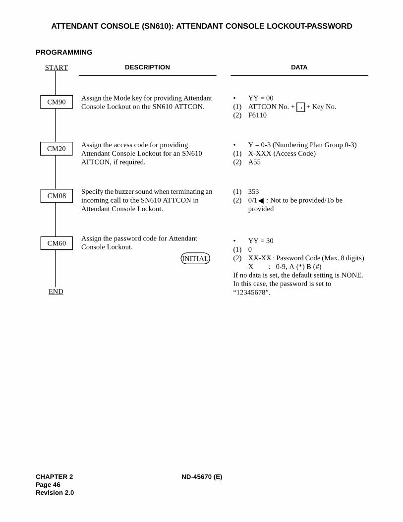
ATTENDANT CONSOLE (SN610): ATTENDANT CONSOLE LOCKOUT-PASSWORD
PROGRAMMING
DESCRIPTION DATA
Assign the Mode key for providing Attendant Console Lockout on the SN610 ATTCON.
• YY = 00(1) ATTCON No. + + Key No. (2) F6110
Assign the access code for providing Attendant Console Lockout for an SN610 ATTCON, if required.
• Y = 0-3 (Numbering Plan Group 0-3) (1) X-XXX (Access Code) (2) A55
Specify the buzzer sound when terminating an incoming call to the SN610 ATTCON in Attendant Console Lockout.
(1) 353(2) 0/1 : Not to be provided/To be
provided
Assign the password code for Attendant Console Lockout.
• YY = 30(1) 0 (2) XX-XX : Password Code (Max. 8 digits)
X : 0-9, A (*) B (#) If no data is set, the default setting is NONE.In this case, the password is set to “12345678”.END
CM20
CM08
CM60
CM90
START
,
INITIAL
CHAPTER 2 ND-45670 (E)Page 46Revision 2.0
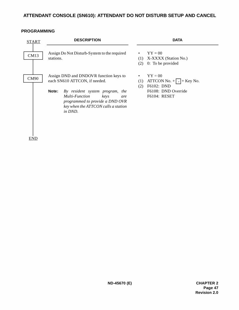
ATTENDANT CONSOLE (SN610): ATTENDANT DO NOT DISTURB SETUP AND CANCEL
PROGRAMMING
DESCRIPTION DATA
Assign Do Not Disturb-System to the required stations.
• YY = 00(1) X-XXXX (Station No.)(2) 0: To be provided
Assign DND and DNDOVR function keys to each SN610 ATTCON, if needed.
Note: By resident system program, theMulti-Function keys areprogrammed to provide a DND OVRkey when the ATTCON calls a stationin DND.
• YY = 00(1) ATTCON No. + + Key No.(2) F6102: DND
F6108: DND OverrideF6104: RESET
END
CM90
CM13
START
,
ND-45670 (E) CHAPTER 2Page 47
Revision 2.0
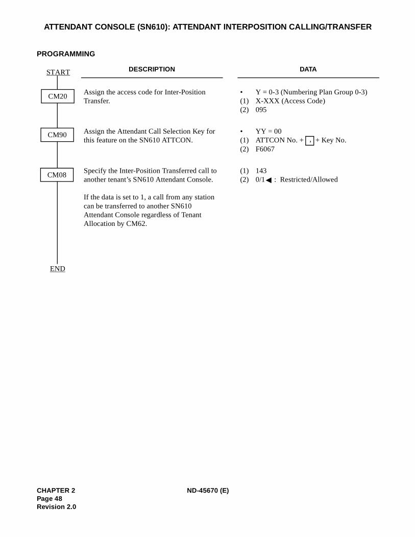
ATTENDANT CONSOLE (SN610): ATTENDANT INTERPOSITION CALLING/TRANSFER
PROGRAMMING
DESCRIPTION DATA
Assign the access code for Inter-Position Transfer.
• Y = 0-3 (Numbering Plan Group 0-3) (1) X-XXX (Access Code) (2) 095
Assign the Attendant Call Selection Key for this feature on the SN610 ATTCON.
• YY = 00(1) ATTCON No. + + Key No. (2) F6067
Specify the Inter-Position Transferred call to another tenant’s SN610 Attendant Console.
If the data is set to 1, a call from any station can be transferred to another SN610 Attendant Console regardless of Tenant Allocation by CM62.
(1) 143 (2) 0/1 : Restricted/Allowed
END
CM90
CM08
CM20
START
,
CHAPTER 2 ND-45670 (E)Page 48Revision 2.0
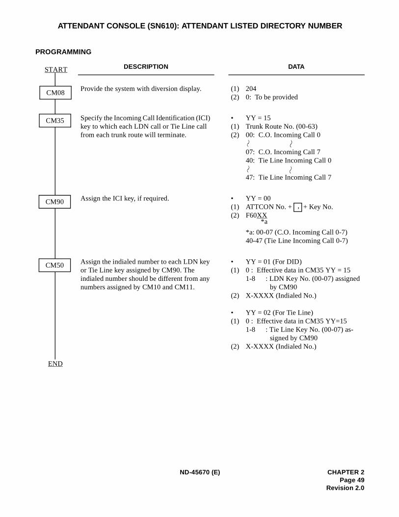
ATTENDANT CONSOLE (SN610): ATTENDANT LISTED DIRECTORY NUMBER
PROGRAMMING
DESCRIPTION DATA
Provide the system with diversion display. (1) 204 (2) 0: To be provided
Specify the Incoming Call Identification (ICI) key to which each LDN call or Tie Line call from each trunk route will terminate.
• YY = 15(1) Trunk Route No. (00-63) (2) 00: C.O. Incoming Call 0
07: C.O. Incoming Call 7 40: Tie Line Incoming Call 0
47: Tie Line Incoming Call 7
Assign the ICI key, if required. • YY = 00(1) ATTCON No. + + Key No. (2) F60XX
*a: 00-07 (C.O. Incoming Call 0-7) 40-47 (Tie Line Incoming Call 0-7)
Assign the indialed number to each LDN key or Tie Line key assigned by CM90. The indialed number should be different from any numbers assigned by CM10 and CM11.
• YY = 01 (For DID)(1) 0 : Effective data in CM35 YY = 15
1-8 : LDN Key No. (00-07) assigned by CM90
(2) X-XXXX (Indialed No.)
• YY = 02 (For Tie Line) (1) 0 : Effective data in CM35 YY=15
1-8 : Tie Line Key No. (00-07) as-signed by CM90
(2) X-XXXX (Indialed No.)
END
CM35
CM90
CM50
CM08
START
,
*a
ND-45670 (E) CHAPTER 2Page 49
Revision 2.0
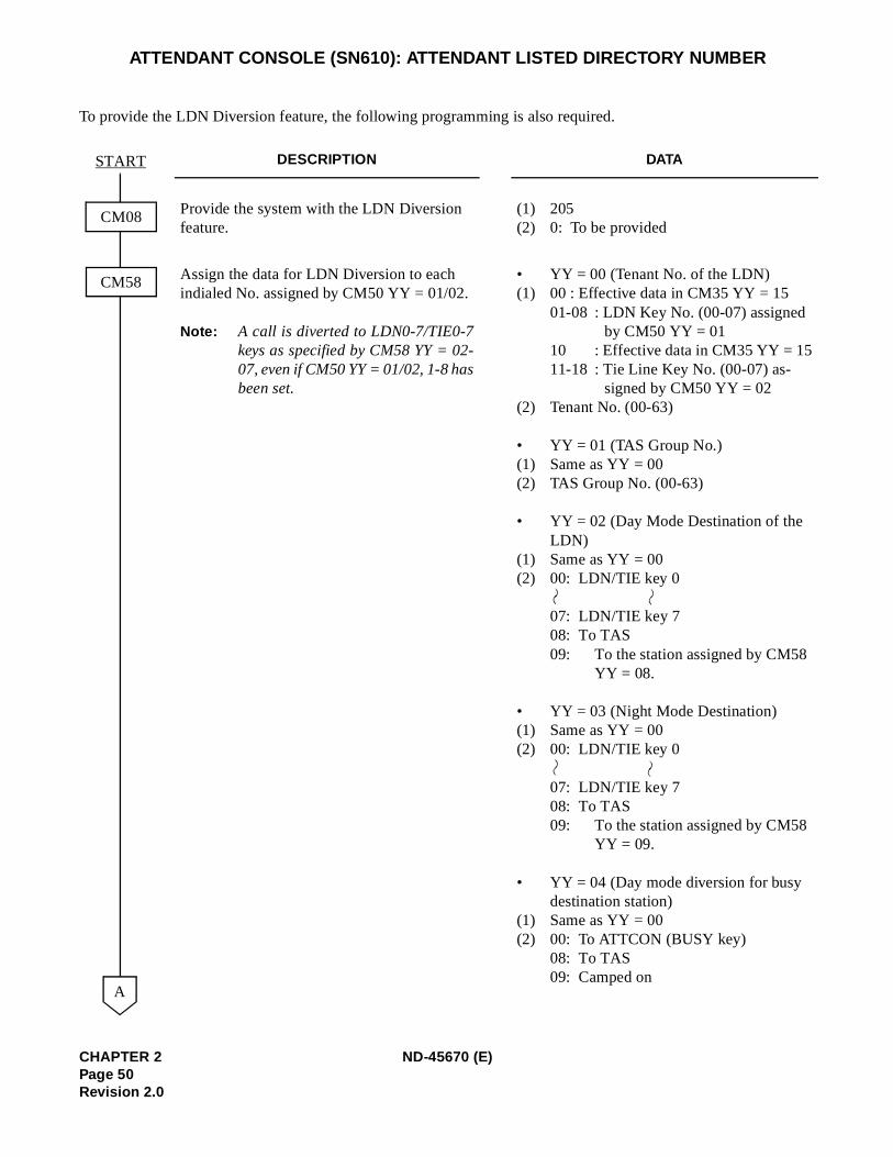
ATTENDANT CONSOLE (SN610): ATTENDANT LISTED DIRECTORY NUMBER
To provide the LDN Diversion feature, the following programming is also required.
DESCRIPTION DATA
Provide the system with the LDN Diversion feature.
(1) 205 (2) 0: To be provided
Assign the data for LDN Diversion to each indialed No. assigned by CM50 YY = 01/02.
Note: A call is diverted to LDN0-7/TIE0-7keys as specified by CM58 YY = 02-07, even if CM50 YY = 01/02, 1-8 hasbeen set.
• YY = 00 (Tenant No. of the LDN)(1) 00 : Effective data in CM35 YY = 15
01-08 : LDN Key No. (00-07) assigned by CM50 YY = 01
10 : Effective data in CM35 YY = 1511-18 : Tie Line Key No. (00-07) as-
signed by CM50 YY = 02(2) Tenant No. (00-63)
• YY = 01 (TAS Group No.)(1) Same as YY = 00 (2) TAS Group No. (00-63)
• YY = 02 (Day Mode Destination of the LDN)
(1) Same as YY = 00 (2) 00: LDN/TIE key 0
07: LDN/TIE key 7 08: To TAS09: To the station assigned by CM58
YY = 08.
• YY = 03 (Night Mode Destination) (1) Same as YY = 00 (2) 00: LDN/TIE key 0
07: LDN/TIE key 7 08: To TAS09: To the station assigned by CM58
YY = 09.
• YY = 04 (Day mode diversion for busy destination station)
(1) Same as YY = 00 (2) 00: To ATTCON (BUSY key)
08: To TAS09: Camped on
CM08
CM58
START
A
CHAPTER 2 ND-45670 (E)Page 50Revision 2.0
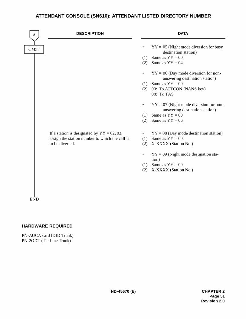
ATTENDANT CONSOLE (SN610): ATTENDANT LISTED DIRECTORY NUMBER
HARDWARE REQUIRED
PN-AUCA card (DID Trunk)PN-2ODT (Tie Line Trunk)
DESCRIPTION DATA
• YY = 05 (Night mode diversion for busy destination station)
(1) Same as YY = 00 (2) Same as YY = 04
• YY = 06 (Day mode diversion for non-answering destination station)
(1) Same as YY = 00 (2) 00: To ATTCON (NANS key)
08: To TAS
• YY = 07 (Night mode diversion for non-answering destination station)
(1) Same as YY = 00 (2) Same as YY = 06
If a station is designated by YY = 02, 03, assign the station number to which the call is to be diverted.
• YY = 08 (Day mode destination station)(1) Same as YY = 00 (2) X-XXXX (Station No.)
• YY = 09 (Night mode destination sta-tion)
(1) Same as YY = 00 (2) X-XXXX (Station No.)
END
A
CM58
ND-45670 (E) CHAPTER 2Page 51
Revision 2.0
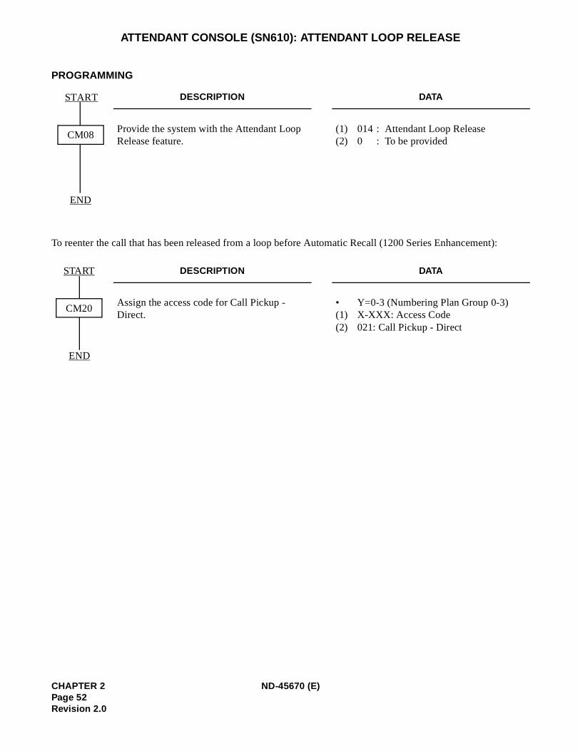
):
ATTENDANT CONSOLE (SN610): ATTENDANT LOOP RELEASE
PROGRAMMING
To reenter the call that has been released from a loop before Automatic Recall (1200 Series Enhancement
DESCRIPTION DATA
Provide the system with the Attendant Loop Release feature.
(1) 014 : Attendant Loop Release (2) 0 : To be provided
DESCRIPTION DATA
Assign the access code for Call Pickup - Direct.
• Y=0-3 (Numbering Plan Group 0-3)(1) X-XXX: Access Code(2) 021: Call Pickup - Direct
END
CM08
START
START
END
CM20
CHAPTER 2 ND-45670 (E)Page 52Revision 2.0
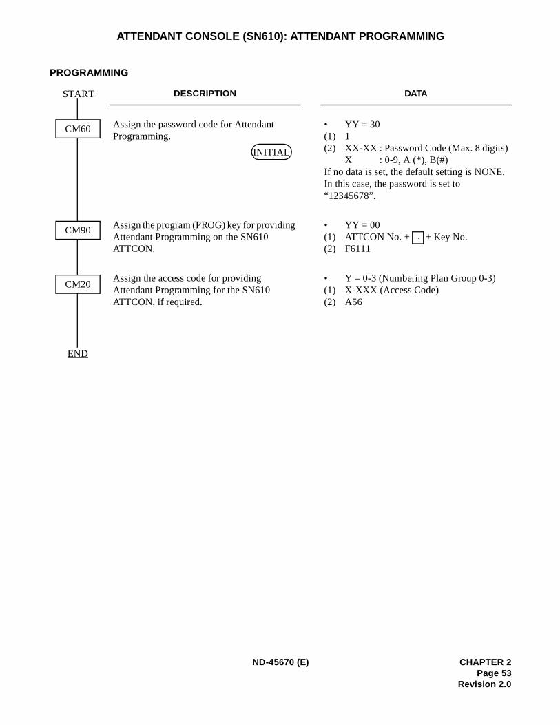
ATTENDANT CONSOLE (SN610): ATTENDANT PROGRAMMING
PROGRAMMING
DESCRIPTION DATA
Assign the password code for Attendant Programming.
• YY = 30 (1) 1 (2) XX-XX : Password Code (Max. 8 digits)
X : 0-9, A (*), B(#) If no data is set, the default setting is NONE.In this case, the password is set to “12345678”.
Assign the program (PROG) key for providing Attendant Programming on the SN610 ATTCON.
• YY = 00(1) ATTCON No. + + Key No.(2) F6111
Assign the access code for providing Attendant Programming for the SN610 ATTCON, if required.
• Y = 0-3 (Numbering Plan Group 0-3) (1) X-XXX (Access Code) (2) A56
END
CM60
START
CM90
CM20
INITIAL
,
ND-45670 (E) CHAPTER 2Page 53
Revision 2.0
ATTENDANT CONSOLE (SN610): CALL QUEUING
PROGRAMMING
Refer to CALL WAITING DISPLAY.
CHAPTER 2 ND-45670 (E)Page 54Revision 2.0
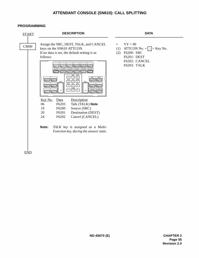
ATTENDANT CONSOLE (SN610): CALL SPLITTING
PROGRAMMING
DESCRIPTION DATA
Assign the SRC, DEST, TALK, and CANCEL keys on the SN610 ATTCON.If no data is set, the default setting is as follows:
Note: TALK key is assigned as a Multi-Function key, during the answer state.
• YY = 00(1) ATTCON No. + + Key No. (2) F6200: SRC
F6201: DEST F6202: CANCEL F6203: TALK
START
END
CM90
Key No. Data Description06 F6203 Talk (TALK) Note19 F6200 Source (SRC) 20 F6201 Destination (DEST) 24 F6202 Cancel (CANCEL)
LO OP1 LOOP2 LOOP3 LOOP4 LOOP5 LOO P6
0 1
ANS
2 5
R LS
2 6
1 2 3
4 5 6
7 8 9
* 0 #
SRC DEST
HOLD CANC EL
13 14
15 16
17 18
1 9 2 0
2 1 2 2
2 3 2 4
0 7
0 2 0 3 0 4 0 5 0 6
0 8 09 1 0 1 1 1 2
ABC DEF
JKL M NOGHI
TUV W X YPRS
OPER
,
ND-45670 (E) CHAPTER 2Page 55
Revision 2.0
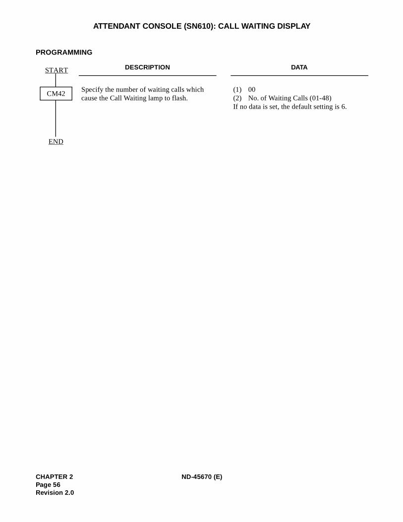
ATTENDANT CONSOLE (SN610): CALL WAITING DISPLAY
PROGRAMMING
DESCRIPTION DATA
Specify the number of waiting calls which cause the Call Waiting lamp to flash.
(1) 00(2) No. of Waiting Calls (01-48)If no data is set, the default setting is 6.
END
CM42
START
CHAPTER 2 ND-45670 (E)Page 56Revision 2.0
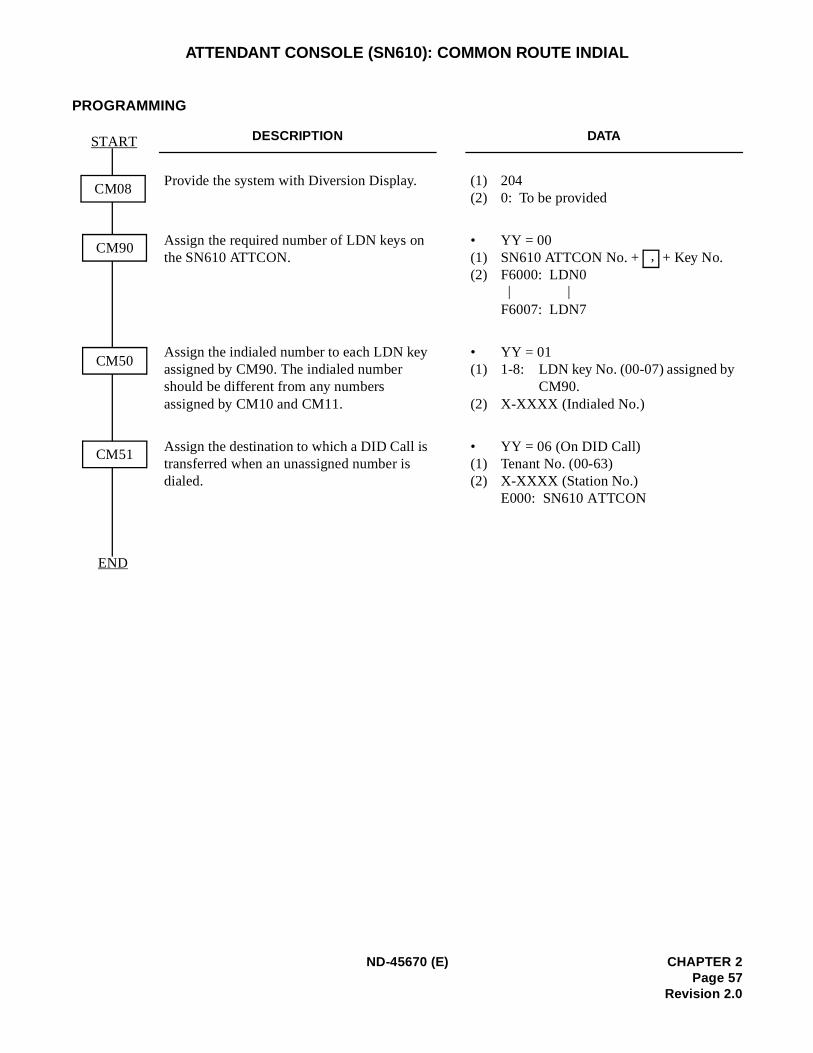
ATTENDANT CONSOLE (SN610): COMMON ROUTE INDIAL
PROGRAMMING
DESCRIPTION DATA
Provide the system with Diversion Display. (1) 204 (2) 0: To be provided
Assign the required number of LDN keys on the SN610 ATTCON.
• YY = 00(1) SN610 ATTCON No. + + Key No.(2) F6000: LDN0
F6007: LDN7
Assign the indialed number to each LDN key assigned by CM90. The indialed number should be different from any numbers assigned by CM10 and CM11.
• YY = 01(1) 1-8: LDN key No. (00-07) assigned by
CM90.(2) X-XXXX (Indialed No.)
Assign the destination to which a DID Call is transferred when an unassigned number is dialed.
• YY = 06 (On DID Call) (1) Tenant No. (00-63)(2) X-XXXX (Station No.)
E000: SN610 ATTCON
END
CM08
START
CM90
CM50
CM51
,
| |
ND-45670 (E) CHAPTER 2Page 57
Revision 2.0
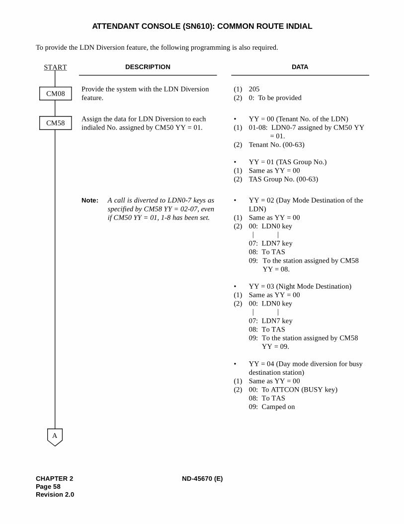
ATTENDANT CONSOLE (SN610): COMMON ROUTE INDIAL
To provide the LDN Diversion feature, the following programming is also required.
DESCRIPTION DATA
Provide the system with the LDN Diversion feature.
(1) 205 (2) 0: To be provided
Assign the data for LDN Diversion to each indialed No. assigned by CM50 YY = 01.
• YY = 00 (Tenant No. of the LDN)(1) 01-08: LDN0-7 assigned by CM50 YY
= 01. (2) Tenant No. (00-63)
• YY = 01 (TAS Group No.)(1) Same as YY = 00 (2) TAS Group No. (00-63)
Note: A call is diverted to LDN0-7 keys asspecified by CM58 YY = 02-07, evenif CM50 YY = 01, 1-8 has been set.
• YY = 02 (Day Mode Destination of the LDN)
(1) Same as YY = 00 (2) 00: LDN0 key
07: LDN7 key 08: To TAS09: To the station assigned by CM58
YY = 08.
• YY = 03 (Night Mode Destination) (1) Same as YY = 00(2) 00: LDN0 key
07: LDN7 key08: To TAS09: To the station assigned by CM58
YY = 09.
• YY = 04 (Day mode diversion for busy destination station)
(1) Same as YY = 00 (2) 00: To ATTCON (BUSY key)
08: To TAS09: Camped on
CM08
CM58
START
A
| |
| |
CHAPTER 2 ND-45670 (E)Page 58Revision 2.0
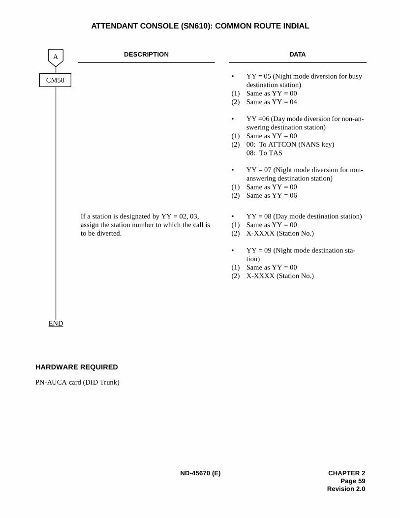
ATTENDANT CONSOLE (SN610): COMMON ROUTE INDIAL
HARDWARE REQUIRED
PN-AUCA card (DID Trunk)
DESCRIPTION DATA
• YY = 05 (Night mode diversion for busy destination station)
(1) Same as YY = 00 (2) Same as YY = 04
• YY =06 (Day mode diversion for non-an-swering destination station)
(1) Same as YY = 00 (2) 00: To ATTCON (NANS key)
08: To TAS
• YY = 07 (Night mode diversion for non-answering destination station)
(1) Same as YY = 00 (2) Same as YY = 06
If a station is designated by YY = 02, 03, assign the station number to which the call is to be diverted.
• YY = 08 (Day mode destination station)(1) Same as YY = 00 (2) X-XXXX (Station No.)
• YY = 09 (Night mode destination sta-tion)
(1) Same as YY = 00 (2) X-XXXX (Station No.)
END
A
CM58
ND-45670 (E) CHAPTER 2Page 59
Revision 2.0
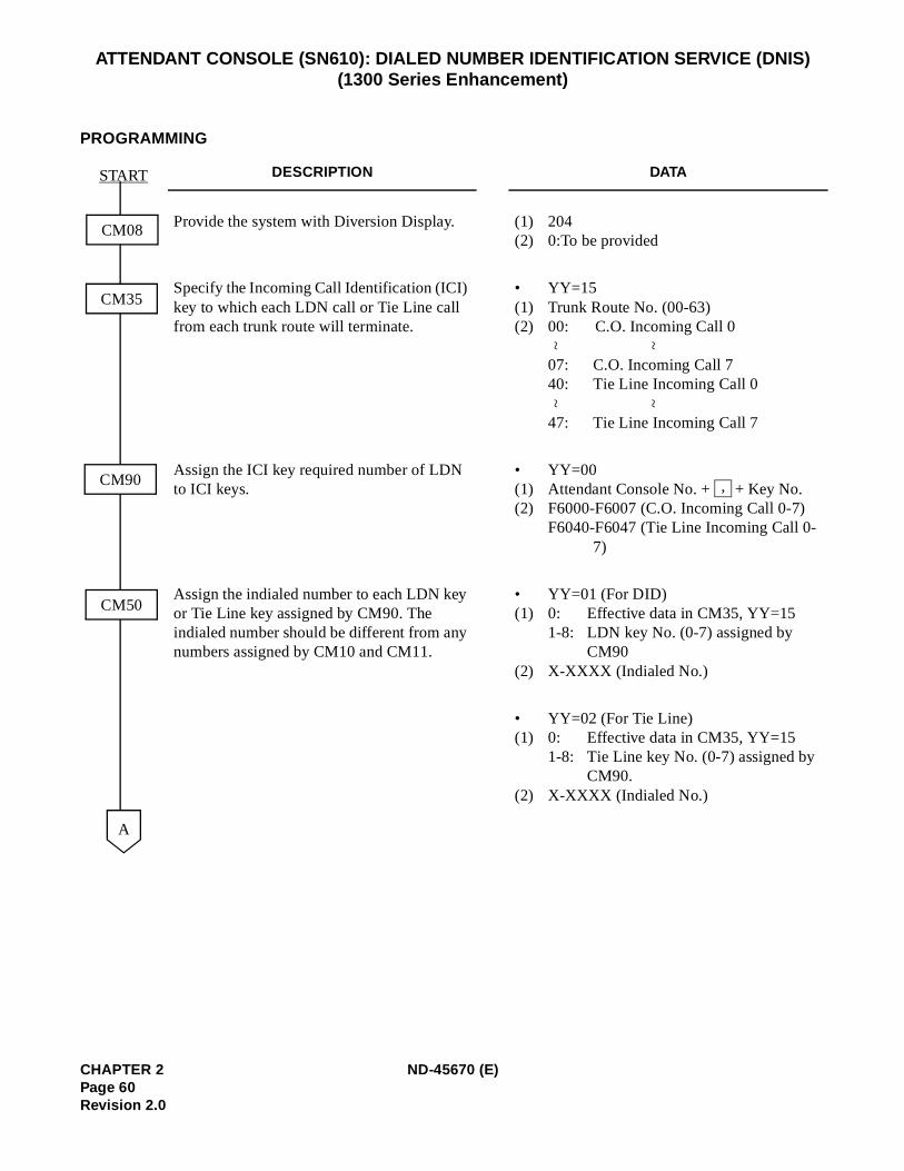
ATTENDANT CONSOLE (SN610): DIALED NUMBER IDENTIFICATION SERVICE (DNIS)(1300 Series Enhancement)
PROGRAMMING
DESCRIPTION DATA
Provide the system with Diversion Display. (1) 204(2) 0:To be provided
Specify the Incoming Call Identification (ICI) key to which each LDN call or Tie Line call from each trunk route will terminate.
• YY=15(1) Trunk Route No. (00-63)(2) 00: C.O. Incoming Call 0
07: C.O. Incoming Call 740: Tie Line Incoming Call 0
47: Tie Line Incoming Call 7
Assign the ICI key required number of LDN to ICI keys.
• YY=00(1) Attendant Console No. + + Key No.(2) F6000-F6007 (C.O. Incoming Call 0-7)
F6040-F6047 (Tie Line Incoming Call 0-7)
Assign the indialed number to each LDN key or Tie Line key assigned by CM90. The indialed number should be different from any numbers assigned by CM10 and CM11.
• YY=01 (For DID)(1) 0: Effective data in CM35, YY=15
1-8: LDN key No. (0-7) assigned by CM90
(2) X-XXXX (Indialed No.)
• YY=02 (For Tie Line)(1) 0: Effective data in CM35, YY=15
1-8: Tie Line key No. (0-7) assigned by CM90.
(2) X-XXXX (Indialed No.)
CM90
CM50
START
A
CM08
CM35
~ ~
~ ~
,
CHAPTER 2 ND-45670 (E)Page 60Revision 2.0
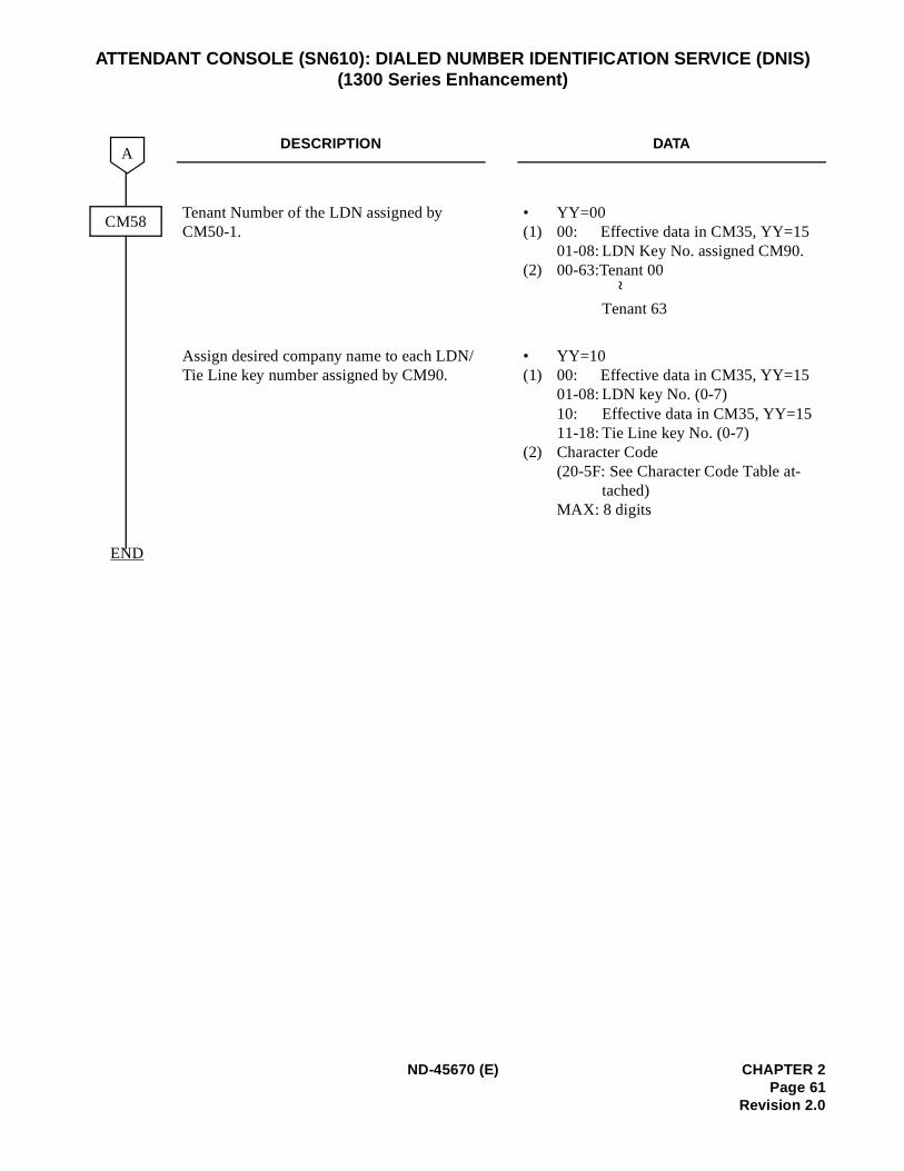
ATTENDANT CONSOLE (SN610): DIALED NUMBER IDENTIFICATION SERVICE (DNIS)(1300 Series Enhancement)
DESCRIPTION DATA
Tenant Number of the LDN assigned by CM50-1.
• YY=00(1) 00: Effective data in CM35, YY=15
01-08: LDN Key No. assigned CM90.(2) 00-63:Tenant 00
Tenant 63
Assign desired company name to each LDN/Tie Line key number assigned by CM90.
• YY=10(1) 00: Effective data in CM35, YY=15
01-08: LDN key No. (0-7)10: Effective data in CM35, YY=1511-18: Tie Line key No. (0-7)
(2) Character Code (20-5F: See Character Code Table at-
tached)MAX: 8 digits
CM58
A
END
~
ND-45670 (E) CHAPTER 2Page 61
Revision 2.0
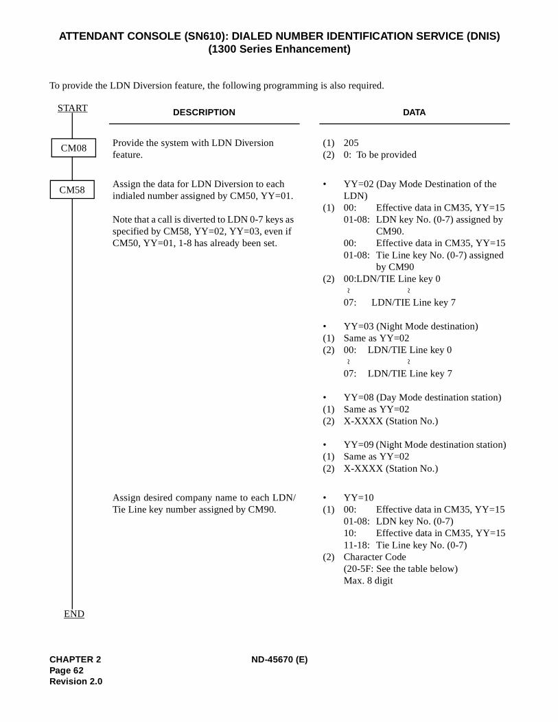
ATTENDANT CONSOLE (SN610): DIALED NUMBER IDENTIFICATION SERVICE (DNIS)(1300 Series Enhancement)
To provide the LDN Diversion feature, the following programming is also required.
DESCRIPTION DATA
Provide the system with LDN Diversion feature.
(1) 205(2) 0: To be provided
Assign the data for LDN Diversion to each indialed number assigned by CM50, YY=01.
Note that a call is diverted to LDN 0-7 keys as specified by CM58, YY=02, YY=03, even if CM50, YY=01, 1-8 has already been set.
• YY=02 (Day Mode Destination of the LDN)
(1) 00: Effective data in CM35, YY=1501-08: LDN key No. (0-7) assigned by
CM90.00: Effective data in CM35, YY=1501-08: Tie Line key No. (0-7) assigned
by CM90(2) 00:LDN/TIE Line key 0
07: LDN/TIE Line key 7
• YY=03 (Night Mode destination)(1) Same as YY=02(2) 00: LDN/TIE Line key 0
07: LDN/TIE Line key 7
• YY=08 (Day Mode destination station)(1) Same as YY=02(2) X-XXXX (Station No.)
• YY=09 (Night Mode destination station)(1) Same as YY=02(2) X-XXXX (Station No.)
Assign desired company name to each LDN/Tie Line key number assigned by CM90.
• YY=10(1) 00: Effective data in CM35, YY=15
01-08: LDN key No. (0-7)10: Effective data in CM35, YY=1511-18: Tie Line key No. (0-7)
(2) Character Code(20-5F: See the table below)Max. 8 digit
CM08
CM58
END
START
~ ~
~ ~
CHAPTER 2 ND-45670 (E)Page 62Revision 2.0
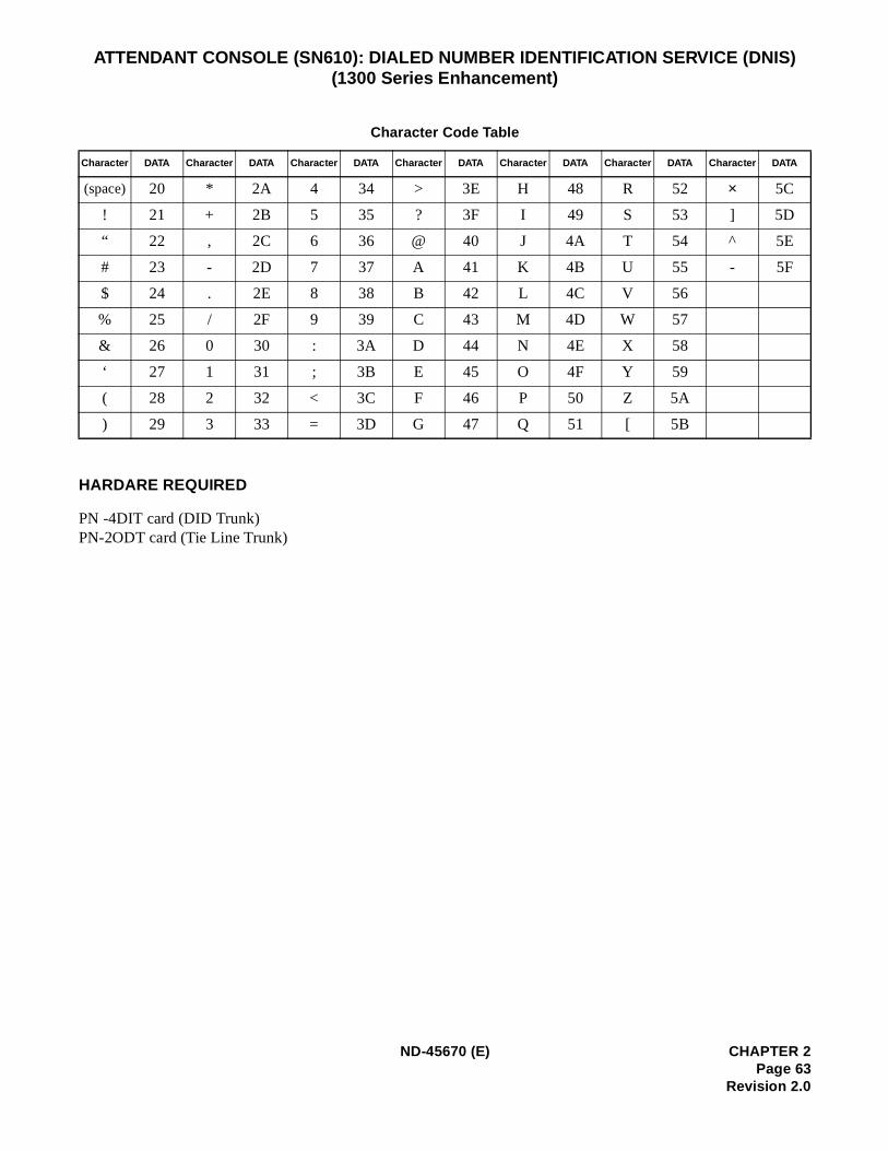
ATTENDANT CONSOLE (SN610): DIALED NUMBER IDENTIFICATION SERVICE (DNIS)(1300 Series Enhancement)
HARDARE REQUIRED
PN -4DIT card (DID Trunk)PN-2ODT card (Tie Line Trunk)
Character Code Table
Character DATA Character DATA Character DATA Character DATA Character DATA Character DATA Character DATA
(space) 20 * 2A 4 34 > 3E H 48 R 52 × 5C
! 21 + 2B 5 35 ? 3F I 49 S 53 ] 5D
“ 22 , 2C 6 36 @ 40 J 4A T 54 ^ 5E
# 23 - 2D 7 37 A 41 K 4B U 55 - 5F
$ 24 . 2E 8 38 B 42 L 4C V 56
% 25 / 2F 9 39 C 43 M 4D W 57
& 26 0 30 : 3A D 44 N 4E X 58
‘ 27 1 31 ; 3B E 45 O 4F Y 59
( 28 2 32 < 3C F 46 P 50 Z 5A
) 29 3 33 = 3D G 47 Q 51 [ 5B
ND-45670 (E) CHAPTER 2Page 63
Revision 2.0
d Di-
ATTENDANT CONSOLE (SN610): INCOMING CALL IDENTIFICATION
PROGRAMMING
Refer to Attendant Called/Calling Number, Attendant Call Selection, Attendant Source Key, Attendant Listerected Number, and Common Route Indial.
CHAPTER 2 ND-45670 (E)Page 64Revision 2.0
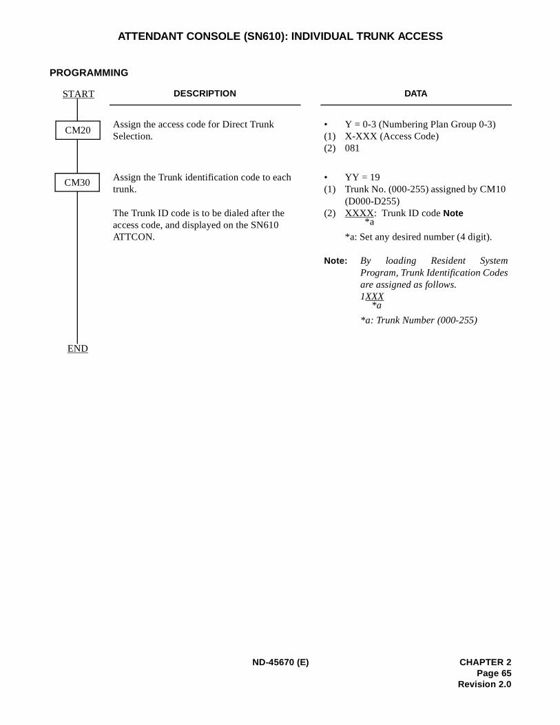
ATTENDANT CONSOLE (SN610): INDIVIDUAL TRUNK ACCESS
PROGRAMMING
DESCRIPTION DATA
Assign the access code for Direct Trunk Selection.
• Y = 0-3 (Numbering Plan Group 0-3) (1) X-XXX (Access Code) (2) 081
Assign the Trunk identification code to each trunk.
The Trunk ID code is to be dialed after the access code, and displayed on the SN610 ATTCON.
• YY = 19(1) Trunk No. (000-255) assigned by CM10
(D000-D255)(2) XXXX : Trunk ID code Note
*a: Set any desired number (4 digit).
Note: By loading Resident SystemProgram, Trunk Identification Codesare assigned as follows. 1XXX
*a: Trunk Number (000-255)
END
CM30
CM20
START
*a
*a
ND-45670 (E) CHAPTER 2Page 65
Revision 2.0
ATTENDANT CONSOLE (SN610): MULTIPLE CONSOLE OPERATION
PROGRAMMING
Refer to ATTENDANT CONSOLE (SN610 ATTCON).
CHAPTER 2 ND-45670 (E)Page 66Revision 2.0
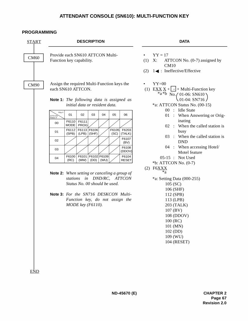
ATTENDANT CONSOLE (SN610): MULTI-FUNCTION KEY
PROGRAMMING
DESCRIPTION DATA
Provide each SN610 ATTCON Multi-Function key capability.
• YY = 17(1) X: ATTCON No. (0-7) assigned by
CM10(2) 1 : Ineffective/Effective
Assign the required Multi-Function keys the each SN610 ATTCON.
Note 1: The following data is assigned asinitial data or resident data.
Note 2: When setting or canceling a group ofstations in DND/RC, ATTCONStatus No. 00 should be used.
Note 3: For the SN716 DESKCON Multi-Function key, do not assign theMODE key (F6110).
• YY=00 (1) EXX X + + Multi-Function key
No. 01-06: SN61001-04: SN716
*a: ATTCON Status No. (00-15)00 : Idle State01 : When Answering or Orig-
inating02 : When the called station is
busy03 : When the called station is
DND04 : When accessing Hotel/
Motel feature05-15 : Not Used
*b: ATTCON No. (0-7) (2) F6XXX
*a: Setting Data (000-255)105 (SC)106 (SHF)112 (SPB)113 (LPB)203 (TALK)107 (BV)108 (DDOV)100 (RC)101 (MN)102 (DD)109 (WU)104 (RESET)
CM60
CM90
START
END
Key #
ATTCONStatus #
01 02 03 04 05 06
00
01
02
03
04
F6110MODE
F6112(SPB)
F6100(RC)
F6111PROG
F6101(MW)
F6113(LPB)
F6106(SHF)
F6102(DD)
F6109(WU)
F6105(SC)
F6203(TALK)
F6104RESET
F6107(BV)
F6108(DDOV)
,*b*a
*a
ND-45670 (E) CHAPTER 2Page 67
Revision 2.0
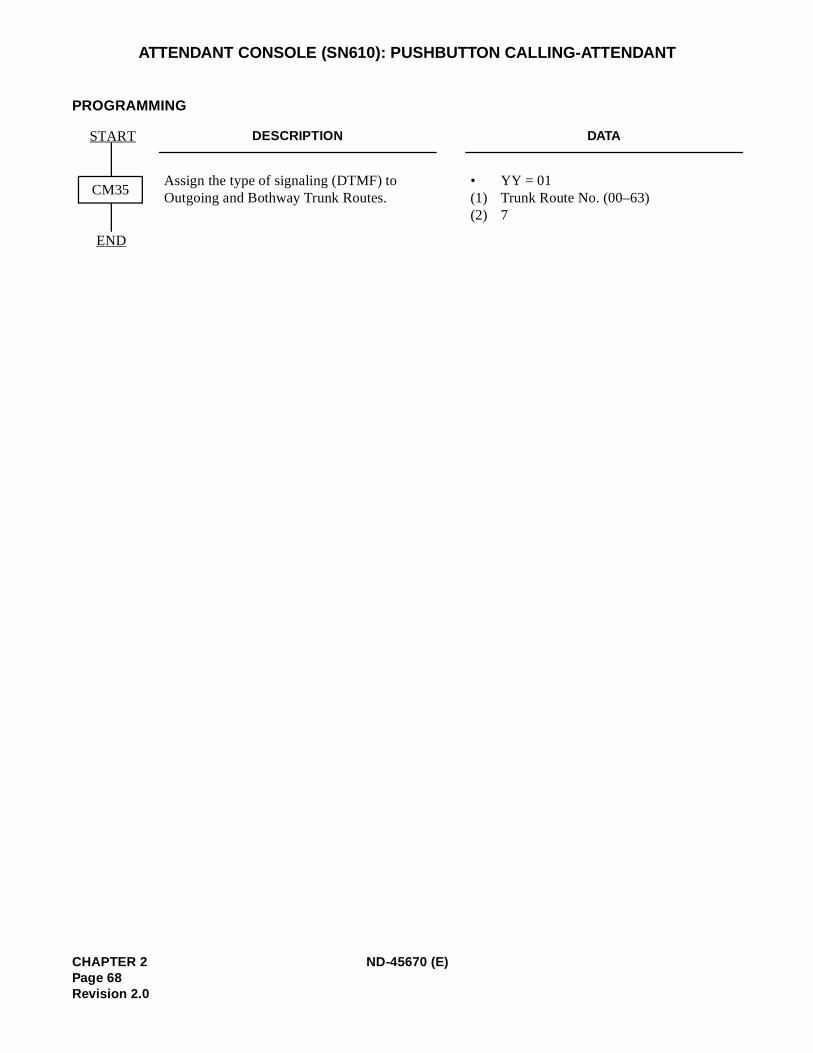
ATTENDANT CONSOLE (SN610): PUSHBUTTON CALLING-ATTENDANT
PROGRAMMING
DESCRIPTION DATA
Assign the type of signaling (DTMF) to Outgoing and Bothway Trunk Routes.
• YY = 01 (1) Trunk Route No. (00–63)(2) 7
CM35
END
START
CHAPTER 2 ND-45670 (E)Page 68Revision 2.0
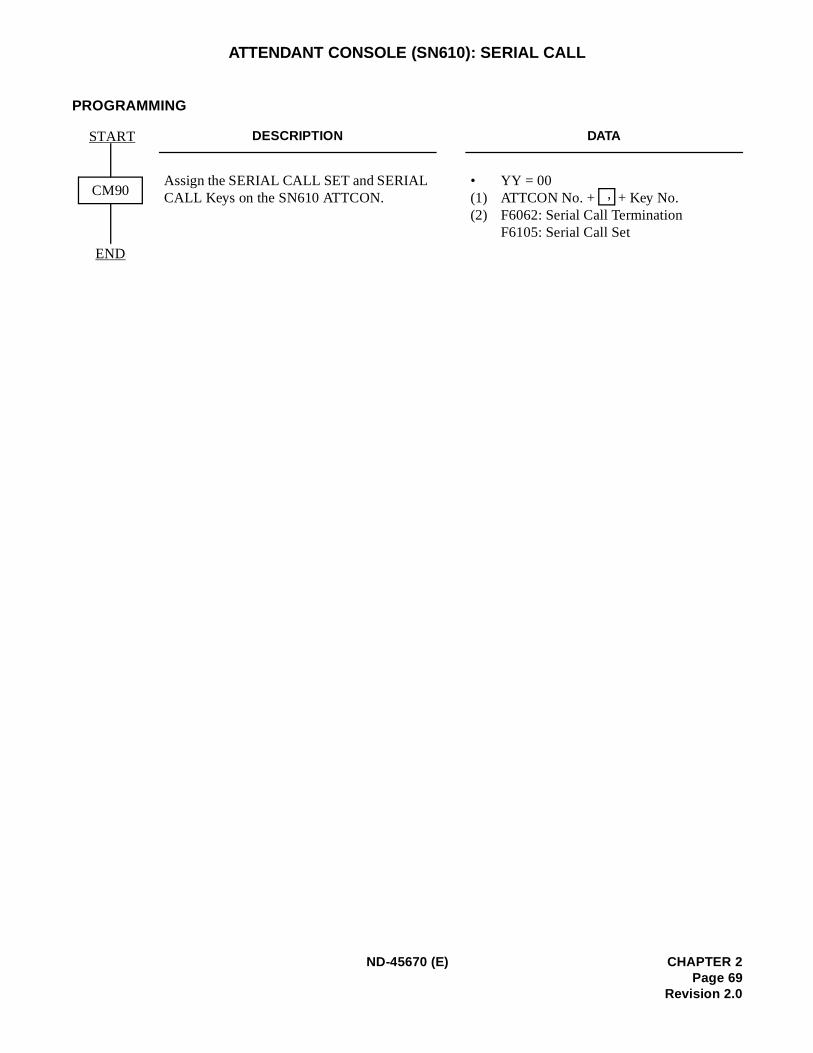
ATTENDANT CONSOLE (SN610): SERIAL CALL
PROGRAMMING
DESCRIPTION DATA
Assign the SERIAL CALL SET and SERIAL CALL Keys on the SN610 ATTCON.
• YY = 00 (1) ATTCON No. + + Key No. (2) F6062: Serial Call Termination
F6105: Serial Call Set
CM90
START
END
,
ND-45670 (E) CHAPTER 2Page 69
Revision 2.0
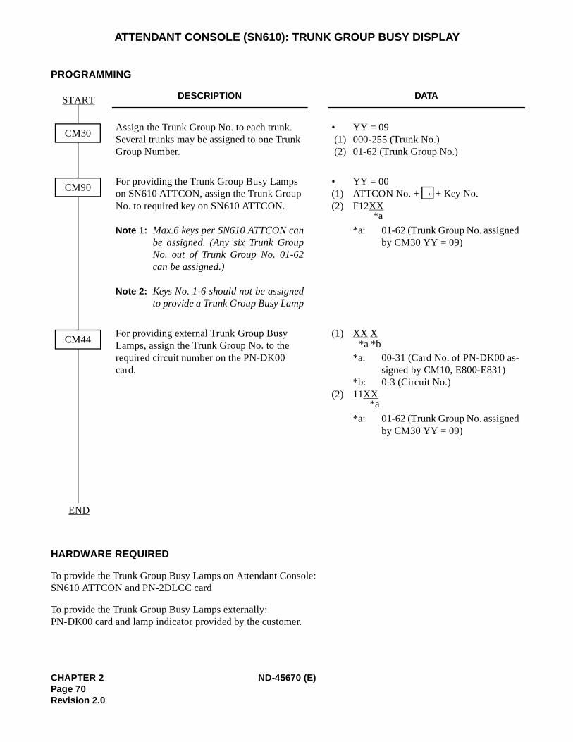
ATTENDANT CONSOLE (SN610): TRUNK GROUP BUSY DISPLAY
PROGRAMMING
HARDWARE REQUIRED
To provide the Trunk Group Busy Lamps on Attendant Console: SN610 ATTCON and PN-2DLCC card
To provide the Trunk Group Busy Lamps externally:PN-DK00 card and lamp indicator provided by the customer.
DESCRIPTION DATA
Assign the Trunk Group No. to each trunk. Several trunks may be assigned to one Trunk Group Number.
• YY = 09 (1) 000-255 (Trunk No.) (2) 01-62 (Trunk Group No.)
For providing the Trunk Group Busy Lamps on SN610 ATTCON, assign the Trunk Group No. to required key on SN610 ATTCON.
Note 1: Max.6 keys per SN610 ATTCON canbe assigned. (Any six Trunk GroupNo. out of Trunk Group No. 01-62can be assigned.)
Note 2: Keys No. 1-6 should not be assignedto provide a Trunk Group Busy Lamp
• YY = 00(1) ATTCON No. + + Key No. (2) F12XX
*a: 01-62 (Trunk Group No. assignedby CM30 YY = 09)
For providing external Trunk Group Busy Lamps, assign the Trunk Group No. to the required circuit number on the PN-DK00 card.
(1) XX X
*a: 00-31 (Card No. of PN-DK00 as-signed by CM10, E800-E831)
*b: 0-3 (Circuit No.)(2) 11XX
*a: 01-62 (Trunk Group No. assignedby CM30 YY = 09)
CM30
START
CM90
CM44
END
,
*a
*b*a
*a
CHAPTER 2 ND-45670 (E)Page 70Revision 2.0
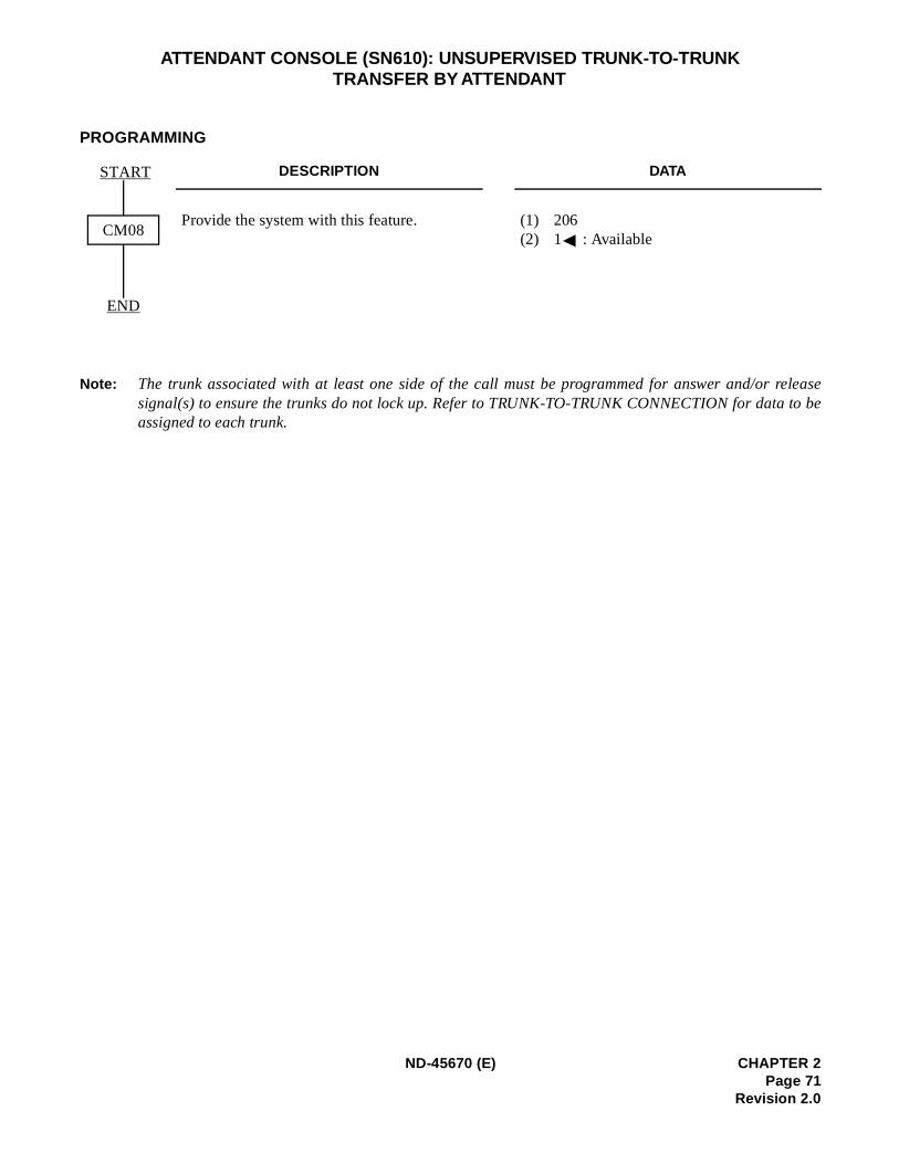
release to be
ATTENDANT CONSOLE (SN610): UNSUPERVISED TRUNK-TO-TRUNK TRANSFER BY ATTENDANT
PROGRAMMING
Note: The trunk associated with at least one side of the call must be programmed for answer and/or signal(s) to ensure the trunks do not lock up. Refer to TRUNK-TO-TRUNK CONNECTION for dataassigned to each trunk.
DESCRIPTION DATA
Provide the system with this feature. (1) 206(2) 1 : AvailableCM08
START
END
ND-45670 (E) CHAPTER 2Page 71
Revision 2.0
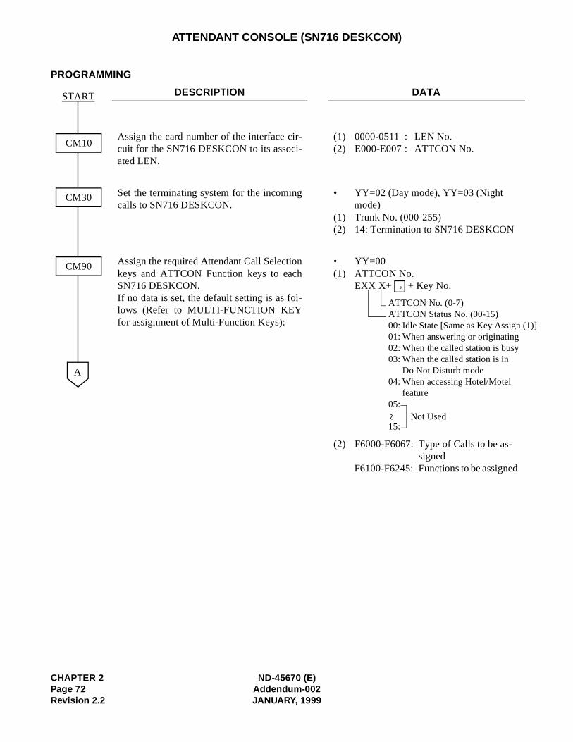
(1)]
ATTENDANT CONSOLE (SN716 DESKCON)
PROGRAMMING
DESCRIPTION DATA
Assign the card number of the interface cir-cuit for the SN716 DESKCON to its associ-ated LEN.
(1) 0000-0511 : LEN No.(2) E000-E007 : ATTCON No.
Set the terminating system for the incomingcalls to SN716 DESKCON.
• YY=02 (Day mode), YY=03 (Night mode)
(1) Trunk No. (000-255)(2) 14: Termination to SN716 DESKCON
Assign the required Attendant Call Selectionkeys and ATTCON Function keys to eachSN716 DESKCON.If no data is set, the default setting is as fol-lows (Refer to MULTI-FUNCTION KEYfor assignment of Multi-Function Keys):
• YY=00(1) ATTCON No.
EXX X+ + Key No.
(2) F6000-F6067: Type of Calls to be as-signed
F6100-F6245: Functions to be assigned
CM10
CM30
START
A
CM90
ATTCON No. (0-7)ATTCON Status No. (00-15)00: Idle State [Same as Key Assign01: When answering or originating02: When the called station is busy03: When the called station is in
Do Not Disturb mode04: When accessing Hotel/Motel
feature05:
15:
~ Not Used
,
CHAPTER 2 ND-45670 (E)Page 72 Addendum-002Revision 2.2 JANUARY, 1999
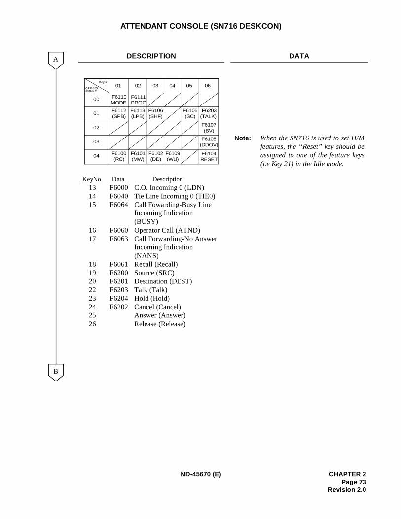
s
ATTENDANT CONSOLE (SN716 DESKCON)
DESCRIPTION DATA
Key No. Data Description 13 F6000 C.O. Incoming 0 (LDN)14 F6040 Tie Line Incoming 0 (TIE0)15 F6064 Call Fowarding-Busy Line
Incoming Indication(BUSY)
16 F6060 Operator Call (ATND)17 F6063 Call Forwarding-No Answer
Incoming Indication(NANS)
18 F6061 Recall (Recall)19 F6200 Source (SRC)20 F6201 Destination (DEST)22 F6203 Talk (Talk)23 F6204 Hold (Hold)24 F6202 Cancel (Cancel) 25 Answer (Answer) 26 Release (Release)
Note: When the SN716 is used to set H/Mfeatures, the “Reset” key should beassigned to one of the feature key(i.e Key 21) in the Idle mode.
A
B
Key #
ATTCONStatus #
01 02 03 04 05 06
00
01
02
03
04
F6110MODE
F6112(SPB)
F6100(RC)
F6111PROG
F6101(MW)
F6113(LPB)
F6106(SHF)
F6102(DD)
F6109(WU)
F6105(SC)
F6203(TALK)
F6104RESET
F6107(BV)
F6108(DDOV)
ND-45670 (E) CHAPTER 2Page 73
Revision 2.0
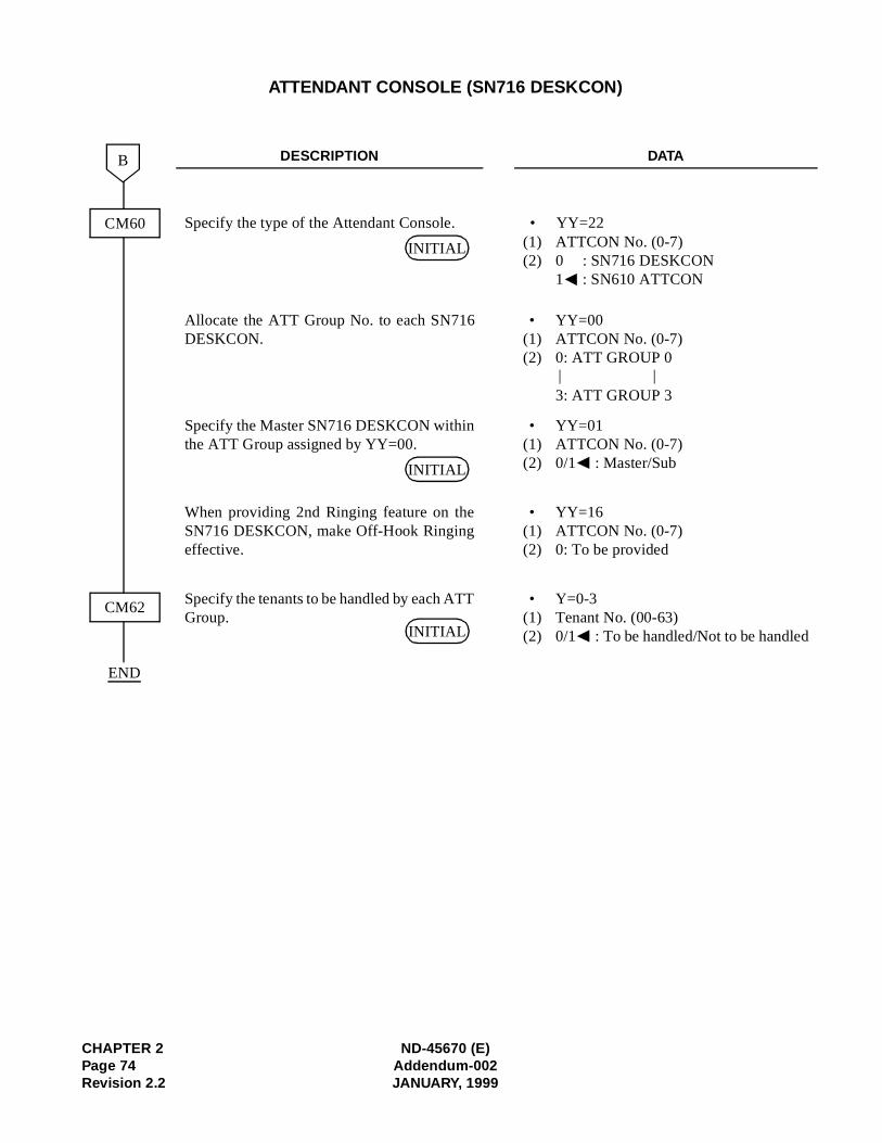
d
ATTENDANT CONSOLE (SN716 DESKCON)
DESCRIPTION DATA
Specify the type of the Attendant Console. • YY=22(1) ATTCON No. (0-7)(2) 0 : SN716 DESKCON
1 : SN610 ATTCON
Allocate the ATT Group No. to each SN716DESKCON.
• YY=00(1) ATTCON No. (0-7)(2) 0: ATT GROUP 0
3: ATT GROUP 3
Specify the Master SN716 DESKCON withinthe ATT Group assigned by YY=00.
• YY=01(1) ATTCON No. (0-7) (2) 0/1 : Master/Sub
When providing 2nd Ringing feature on theSN716 DESKCON, make Off-Hook Ringingeffective.
• YY=16(1) ATTCON No. (0-7) (2) 0: To be provided
Specify the tenants to be handled by each ATTGroup.
• Y=0-3(1) Tenant No. (00-63)(2) 0/1 : To be handled/Not to be handle
CM60
CM62
B
END
INITIAL
| |
INITIAL
INITIAL
CHAPTER 2 ND-45670 (E)Page 74 Addendum-002Revision 2.2 JANUARY, 1999
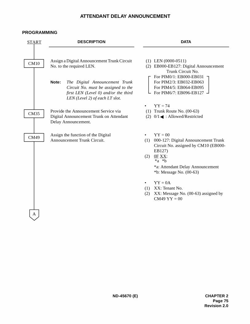
ATTENDANT DELAY ANNOUNCEMENT
PROGRAMMING
DESCRIPTION DATA
Assign a Digital Announcement Trunk Circuit No. to the required LEN.
Note: The Digital Announcement TrunkCircuit No. must be assigned to thefirst LEN (Level 0) and/or the thirdLEN (Level 2) of each LT slot.
(1) LEN (0000-0511) (2) EB000-EB127: Digital Announcement
Trunk Circuit No. For PIM0/1: EB000-EB031For PIM2/3: EB032-EB063For PIM4/5: EB064-EB095For PIM6/7: EB096-EB127
Provide the Announcement Service via Digital Announcement Trunk on Attendant Delay Announcement.
• YY = 74 (1) Trunk Route No. (00-63) (2) 0/1 : Allowed/Restricted
Assign the function of the Digital Announcement Trunk Circuit.
• YY = 00(1) 000-127: Digital Announcement Trunk
Circuit No. assigned by CM10 (EB000-EB127)
(2) 0F XX:
*a: Attendant Delay Announcement*b: Message No. (00-63)
• YY = 0A(1) XX: Tenant No. (2) XX: Message No. (00-63) assigned by
CM49 YY = 00
CM10
START
CM35
CM49
A
*b*a
ND-45670 (E) CHAPTER 2Page 75
Revision 2.0
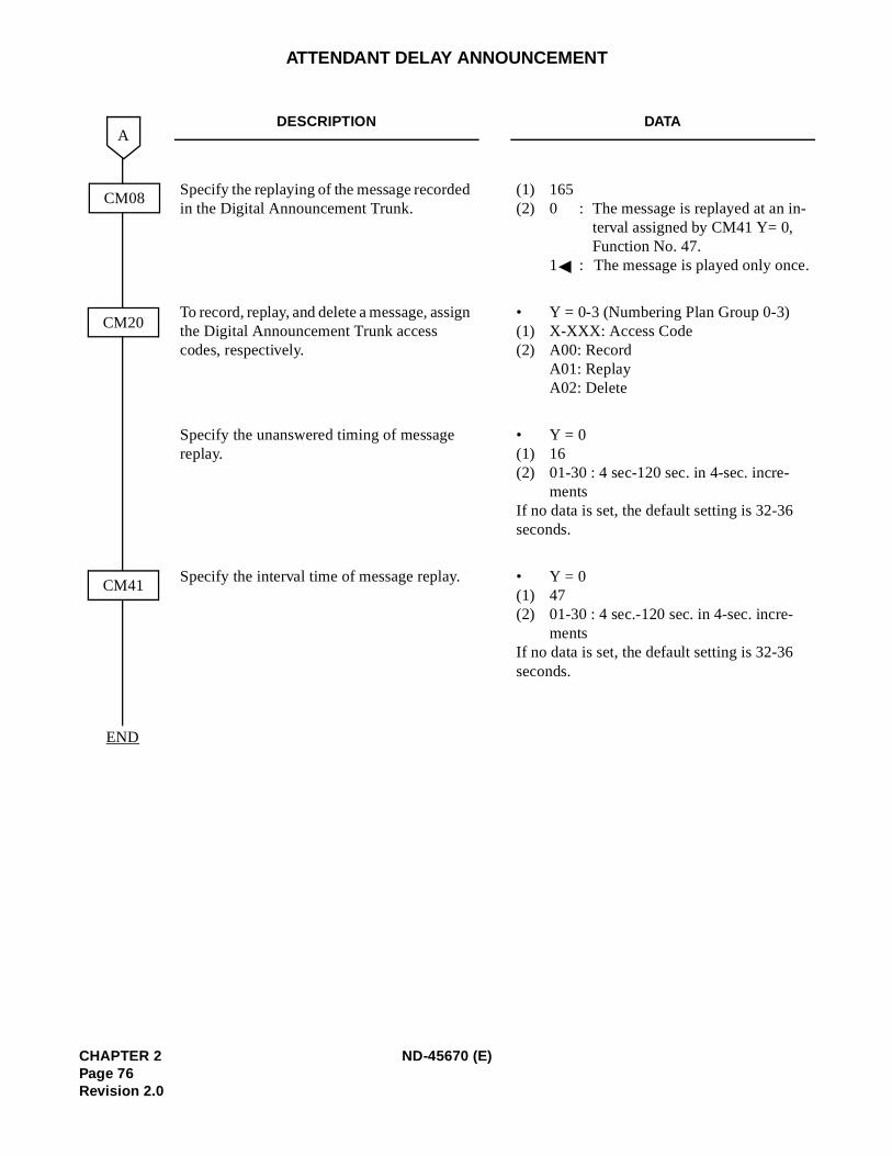
-
.
ATTENDANT DELAY ANNOUNCEMENT
DESCRIPTION DATA
Specify the replaying of the message recorded in the Digital Announcement Trunk.
(1) 165(2) 0 : The message is replayed at an in
terval assigned by CM41 Y= 0, Function No. 47.
1 : The message is played only once
To record, replay, and delete a message, assign the Digital Announcement Trunk access codes, respectively.
• Y = 0-3 (Numbering Plan Group 0-3)(1) X-XXX: Access Code(2) A00: Record
A01: ReplayA02: Delete
Specify the unanswered timing of message replay.
• Y = 0(1) 16(2) 01-30 : 4 sec-120 sec. in 4-sec. incre-
mentsIf no data is set, the default setting is 32-36 seconds.
Specify the interval time of message replay. • Y = 0(1) 47(2) 01-30 : 4 sec.-120 sec. in 4-sec. incre-
mentsIf no data is set, the default setting is 32-36 seconds.
CM08
A
CM20
CM41
END
CHAPTER 2 ND-45670 (E)Page 76Revision 2.0
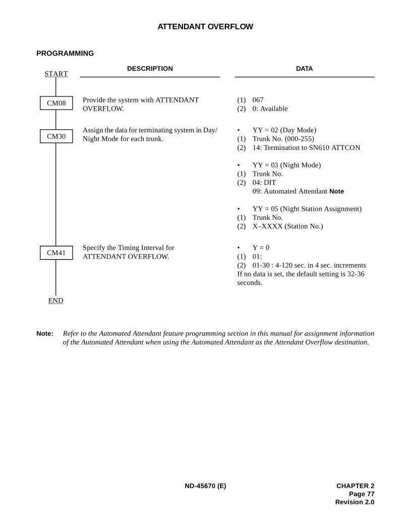
mationation.
ATTENDANT OVERFLOW
PROGRAMMING
Note: Refer to the Automated Attendant feature programming section in this manual for assignment inforof the Automated Attendant when using the Automated Attendant as the Attendant Overflow destin
DESCRIPTION DATA
Provide the system with ATTENDANT OVERFLOW.
(1) 067(2) 0: Available
Assign the data for terminating system in Day/Night Mode for each trunk.
• YY = 02 (Day Mode)(1) Trunk No. (000-255)(2) 14: Termination to SN610 ATTCON
• YY = 03 (Night Mode)(1) Trunk No. (2) 04: DIT
09: Automated Attendant Note
• YY = 05 (Night Station Assignment)(1) Trunk No. (2) X–XXXX (Station No.)
Specify the Timing Interval for ATTENDANT OVERFLOW.
• Y = 0(1) 01:(2) 01-30 : 4-120 sec. in 4 sec. incrementsIf no data is set, the default setting is 32-36 seconds.
CM08
START
CM30
CM41
END
ND-45670 (E) CHAPTER 2Page 77
Revision 2.0
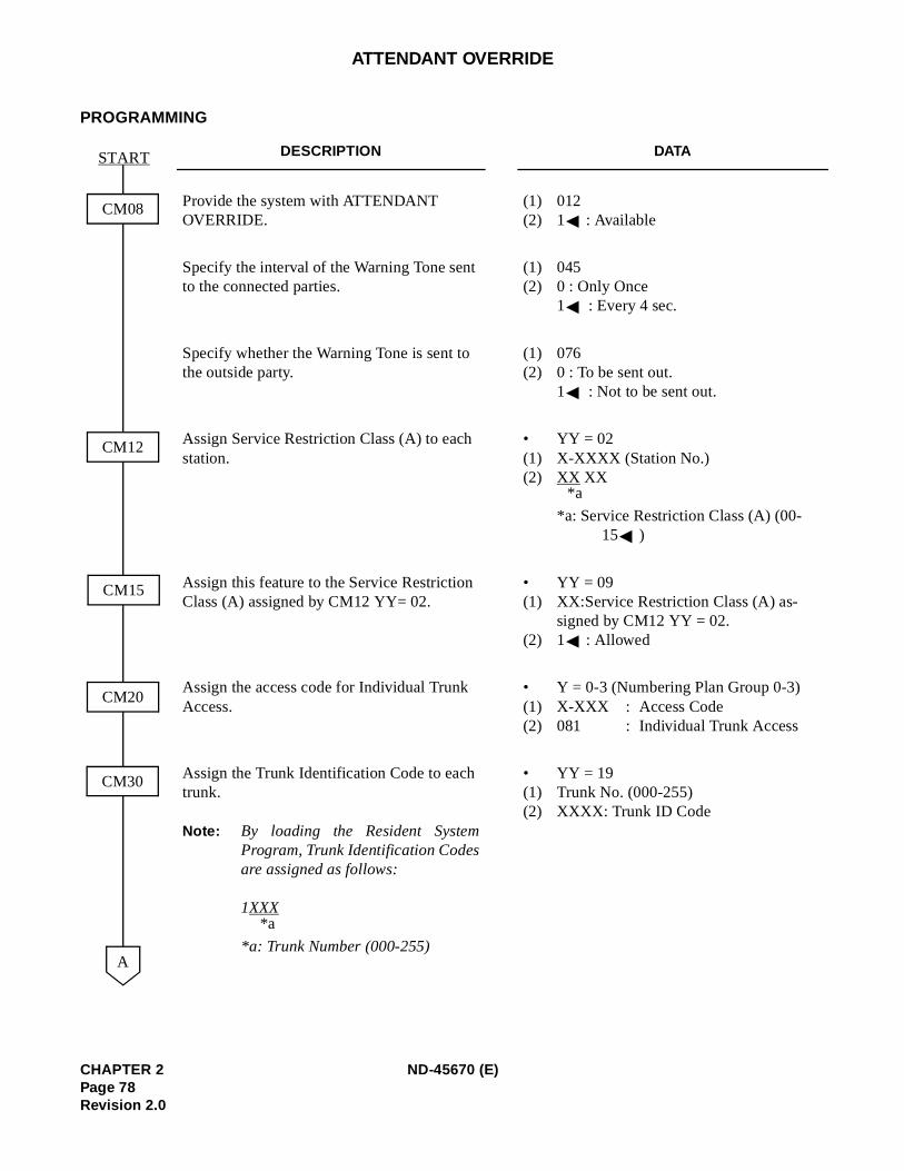
ATTENDANT OVERRIDE
PROGRAMMING
DESCRIPTION DATA
Provide the system with ATTENDANT OVERRIDE.
(1) 012(2) 1 : Available
Specify the interval of the Warning Tone sent to the connected parties.
(1) 045(2) 0 : Only Once
1 : Every 4 sec.
Specify whether the Warning Tone is sent to the outside party.
(1) 076(2) 0 : To be sent out.
1 : Not to be sent out.
Assign Service Restriction Class (A) to each station.
• YY = 02(1) X-XXXX (Station No.)(2) XX XX
*a: Service Restriction Class (A) (00-15 )
Assign this feature to the Service Restriction Class (A) assigned by CM12 YY= 02.
• YY = 09(1) XX:Service Restriction Class (A) as-
signed by CM12 YY = 02.(2) 1 : Allowed
Assign the access code for Individual Trunk Access.
• Y = 0-3 (Numbering Plan Group 0-3)(1) X-XXX : Access Code(2) 081 : Individual Trunk Access
Assign the Trunk Identification Code to each trunk.
Note: By loading the Resident SystemProgram, Trunk Identification Codesare assigned as follows:
1XXX
*a: Trunk Number (000-255)
• YY = 19(1) Trunk No. (000-255)(2) XXXX: Trunk ID Code
CM08
START
CM12
CM15
CM20
CM30
A
*a
*a
CHAPTER 2 ND-45670 (E)Page 78Revision 2.0
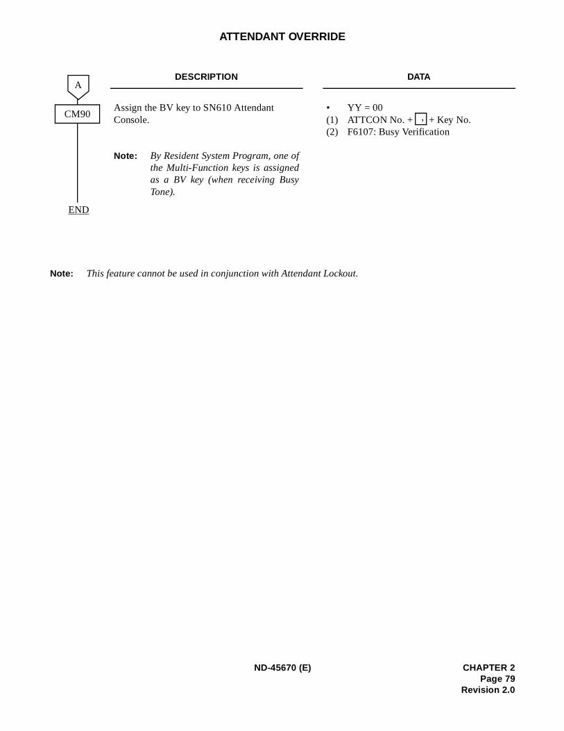
ATTENDANT OVERRIDE
Note: This feature cannot be used in conjunction with Attendant Lockout.
DESCRIPTION DATA
Assign the BV key to SN610 Attendant Console.
Note: By Resident System Program, one ofthe Multi-Function keys is assignedas a BV key (when receiving BusyTone).
• YY = 00(1) ATTCON No. + + Key No. (2) F6107: Busy Verification
CM90
END
A
,
ND-45670 (E) CHAPTER 2Page 79
Revision 2.0
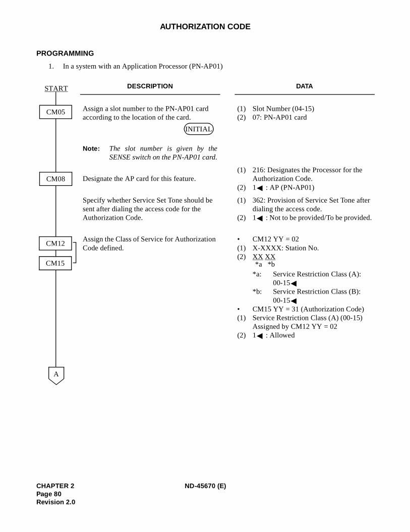
AUTHORIZATION CODE
PROGRAMMING
1. In a system with an Application Processor (PN-AP01)
DESCRIPTION DATA
Assign a slot number to the PN-AP01 card according to the location of the card.
Note: The slot number is given by theSENSE switch on the PN-AP01 card.
(1) Slot Number (04-15)(2) 07: PN-AP01 card
Designate the AP card for this feature.(1) 216: Designates the Processor for the
Authorization Code.(2) 1 : AP (PN-AP01)
Specify whether Service Set Tone should be sent after dialing the access code for the Authorization Code.
(1) 362: Provision of Service Set Tone afterdialing the access code.
(2) 1 : Not to be provided/To be provided.
Assign the Class of Service for Authorization Code defined.
• CM12 YY = 02(1) X-XXXX: Station No. (2) XX XX
*a: Service Restriction Class (A): 00-15
*b: Service Restriction Class (B): 00-15
• CM15 YY = 31 (Authorization Code)(1) Service Restriction Class (A) (00-15)
Assigned by CM12 YY = 02(2) 1 : Allowed
CM05
START
CM08
A
CM12
CM15
INITIAL
*b*a
CHAPTER 2 ND-45670 (E)Page 80Revision 2.0
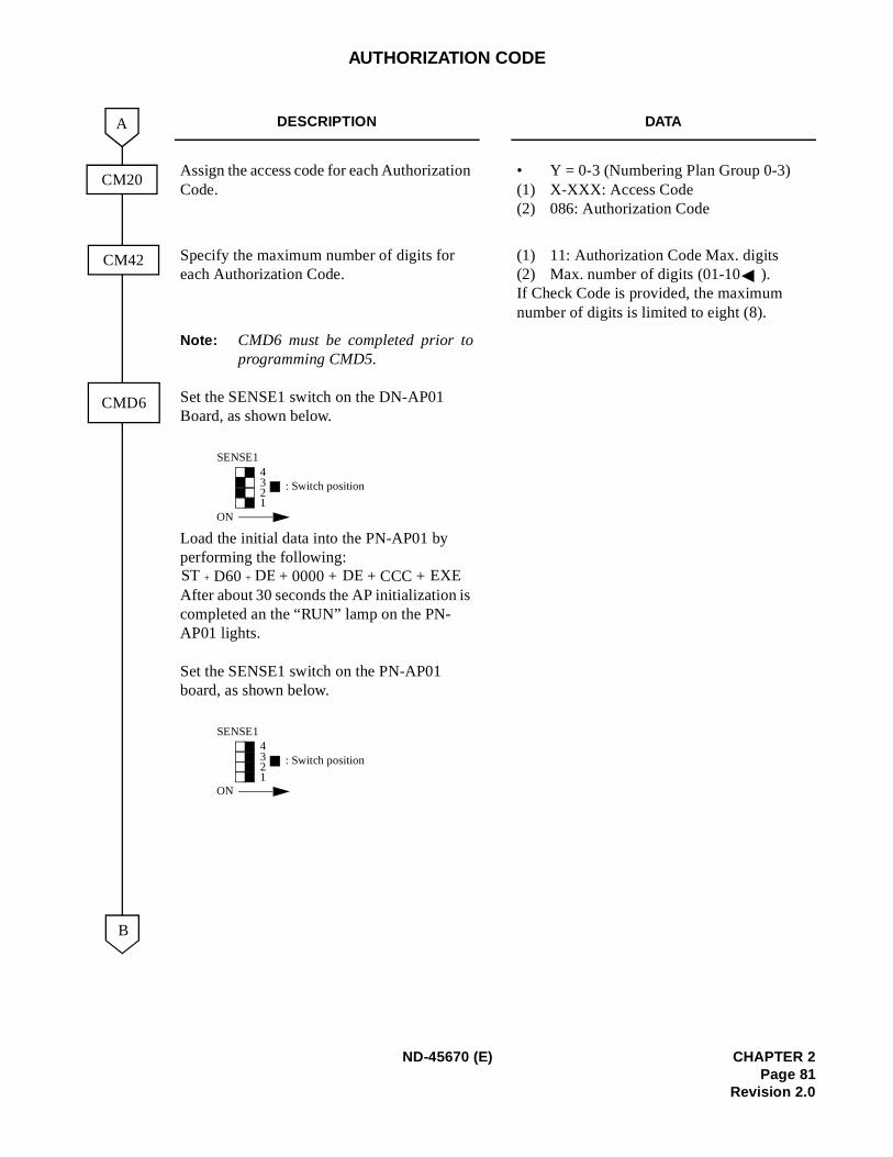
AUTHORIZATION CODE
DESCRIPTION DATA
Assign the access code for each Authorization Code.
• Y = 0-3 (Numbering Plan Group 0-3)(1) X-XXX: Access Code(2) 086: Authorization Code
Specify the maximum number of digits for each Authorization Code.
(1) 11: Authorization Code Max. digits(2) Max. number of digits (01-10 ). If Check Code is provided, the maximum number of digits is limited to eight (8).
Note: CMD6 must be completed prior toprogramming CMD5.
Set the SENSE1 switch on the DN-AP01 Board, as shown below.
Load the initial data into the PN-AP01 by performing the following:
+ D60 + + 0000 + + CCC + After about 30 seconds the AP initialization is completed an the “RUN” lamp on the PN-AP01 lights.
Set the SENSE1 switch on the PN-AP01 board, as shown below.
CM20
B
A
CM42
CMD6
4321
: Switch position
ON
SENSE1
ST DE DE EXE
4321
: Switch position
ON
SENSE1
ND-45670 (E) CHAPTER 2Page 81
Revision 2.0
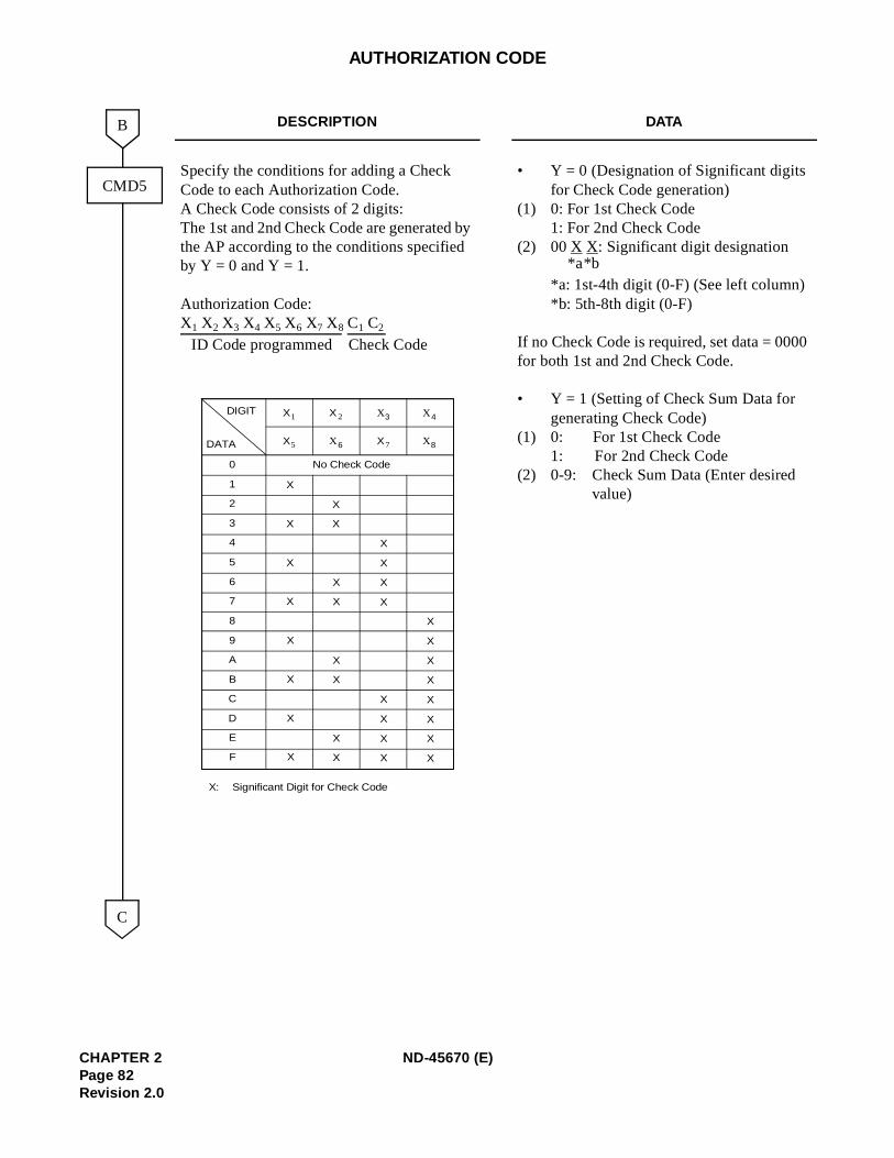
0
AUTHORIZATION CODE
DESCRIPTION DATA
Specify the conditions for adding a Check Code to each Authorization Code.A Check Code consists of 2 digits:The 1st and 2nd Check Code are generated by the AP according to the conditions specified by Y = 0 and Y = 1.
Authorization Code:X1 X2 X3 X4 X5 X6 X7 X8 C1 C2
• Y = 0 (Designation of Significant digits for Check Code generation)
(1) 0: For 1st Check Code1: For 2nd Check Code
(2) 00 X X: Significant digit designation
*a: 1st-4th digit (0-F) (See left column)*b: 5th-8th digit (0-F)
If no Check Code is required, set data = 000for both 1st and 2nd Check Code.
• Y = 1 (Setting of Check Sum Data for generating Check Code)
(1) 0: For 1st Check Code1: For 2nd Check Code
(2) 0-9: Check Sum Data (Enter desired value)
C
CMD5
B
ID Code programmed Check Code
0
1
2
3
4
5
6
7
8
9
A
B
C
D
E
F
X X2 X3 X 4
X5 X 6 X7 X8
DIGIT
DATA
No Check Code
X
X
X
X
X
X
X
X
X
X
X
X
X
X
X
X
X
X
X
X
X
X
X
X
X
X
X
X
X
X
X
X
X: Significant Digit for Check Code
1
*b*a
CHAPTER 2 ND-45670 (E)Page 82Revision 2.0
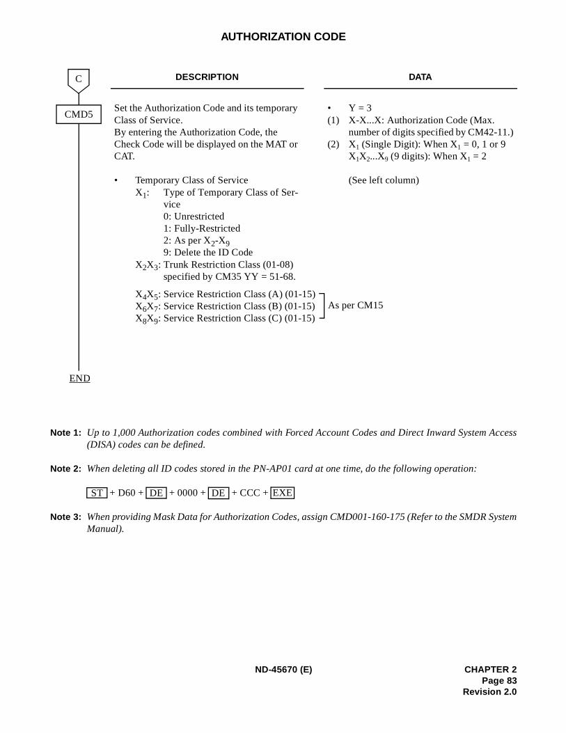
Access
ystem
AUTHORIZATION CODE
Note 1: Up to 1,000 Authorization codes combined with Forced Account Codes and Direct Inward System (DISA) codes can be defined.
Note 2: When deleting all ID codes stored in the PN-AP01 card at one time, do the following operation:
+ D60 + + 0000 + + CCC +
Note 3: When providing Mask Data for Authorization Codes, assign CMD001-160-175 (Refer to the SMDR SManual).
DESCRIPTION DATA
Set the Authorization Code and its temporary Class of Service.By entering the Authorization Code, the Check Code will be displayed on the MAT or CAT.
• Temporary Class of ServiceX1: Type of Temporary Class of Ser-
vice0: Unrestricted1: Fully-Restricted2: As per X2-X99: Delete the ID Code
X2X3: Trunk Restriction Class (01-08) specified by CM35 YY = 51-68.
• Y = 3(1) X-X...X: Authorization Code (Max.
number of digits specified by CM42-11.)(2) X1 (Single Digit): When X1 = 0, 1 or 9
X1X2...X9 (9 digits): When X1 = 2
(See left column)
X4X5: Service Restriction Class (A) (01-15)X6X7: Service Restriction Class (B) (01-15)X8X9: Service Restriction Class (C) (01-15)
CMD5
C
END
As per CM15
ST DE DE EXE
ND-45670 (E) CHAPTER 2Page 83
Revision 2.0
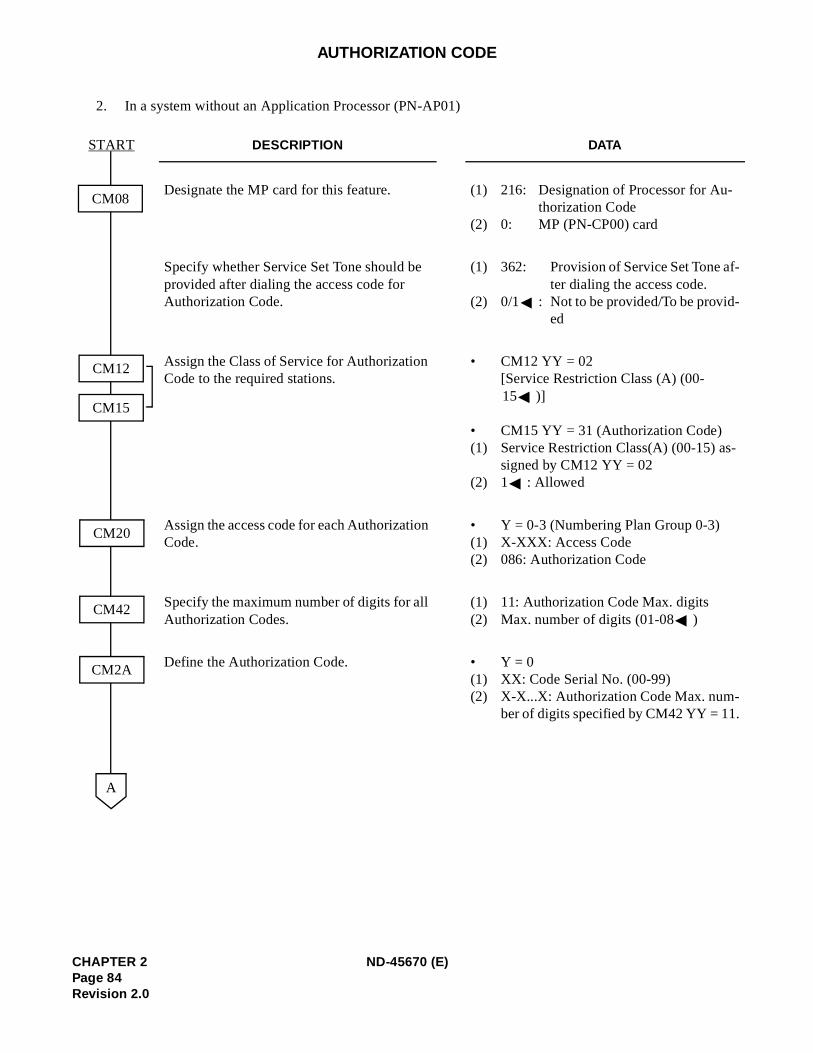
-
-
AUTHORIZATION CODE
2. In a system without an Application Processor (PN-AP01)
DESCRIPTION DATA
Designate the MP card for this feature. (1) 216: Designation of Processor for Authorization Code
(2) 0: MP (PN-CP00) card
Specify whether Service Set Tone should be provided after dialing the access code for Authorization Code.
(1) 362: Provision of Service Set Tone after dialing the access code.
(2) 0/1 : Not to be provided/To be provid-ed
Assign the Class of Service for Authorization Code to the required stations.
• CM12 YY = 02[Service Restriction Class (A) (00-15 )]
• CM15 YY = 31 (Authorization Code)(1) Service Restriction Class(A) (00-15) as-
signed by CM12 YY = 02(2) 1 : Allowed
Assign the access code for each Authorization Code.
• Y = 0-3 (Numbering Plan Group 0-3)(1) X-XXX: Access Code(2) 086: Authorization Code
Specify the maximum number of digits for all Authorization Codes.
(1) 11: Authorization Code Max. digits(2) Max. number of digits (01-08 )
Define the Authorization Code. • Y = 0(1) XX: Code Serial No. (00-99)(2) X-X...X: Authorization Code Max. num-
ber of digits specified by CM42 YY = 11.
CM08
START
CM20
A
CM12
CM15
CM42
CM2A
CHAPTER 2 ND-45670 (E)Page 84Revision 2.0
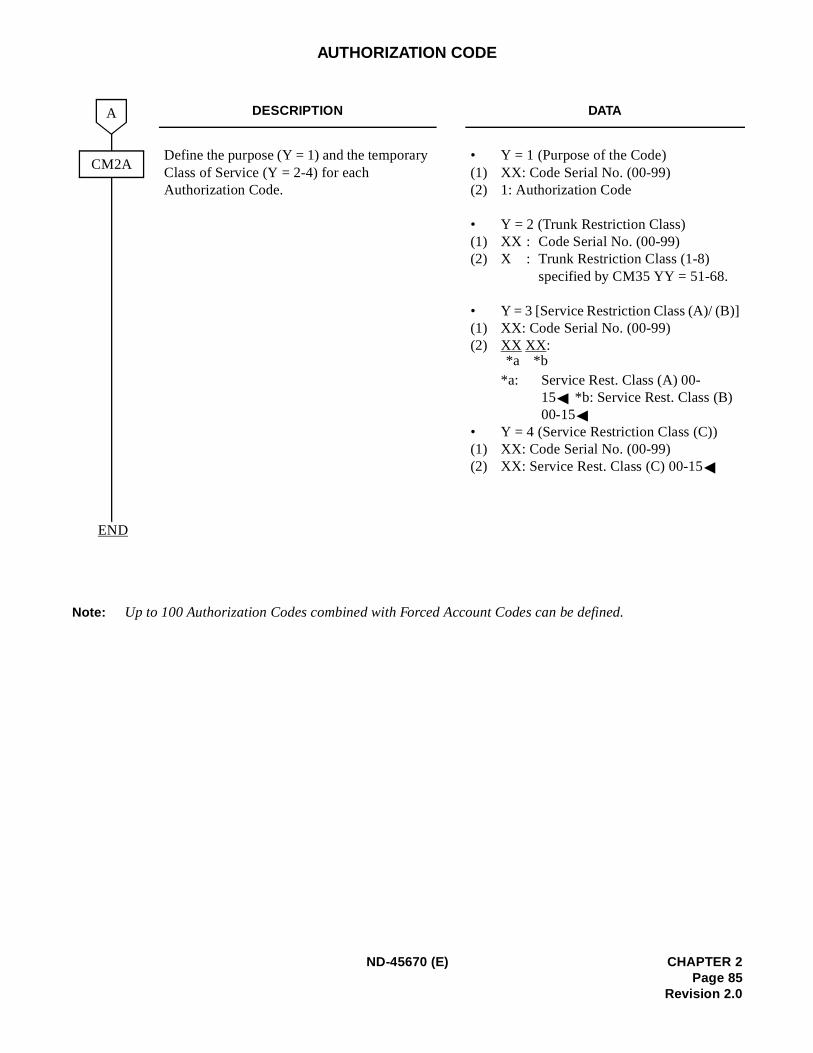
AUTHORIZATION CODE
Note: Up to 100 Authorization Codes combined with Forced Account Codes can be defined.
DESCRIPTION DATA
Define the purpose (Y = 1) and the temporary Class of Service (Y = 2-4) for each Authorization Code.
• Y = 1 (Purpose of the Code)(1) XX: Code Serial No. (00-99)(2) 1: Authorization Code
• Y = 2 (Trunk Restriction Class)(1) XX : Code Serial No. (00-99)(2) X : Trunk Restriction Class (1-8)
specified by CM35 YY = 51-68.
• Y = 3 [Service Restriction Class (A)/ (B)](1) XX: Code Serial No. (00-99)(2) XX XX:
*a: Service Rest. Class (A) 00-15 *b: Service Rest. Class (B) 00-15
• Y = 4 (Service Restriction Class (C))(1) XX: Code Serial No. (00-99)(2) XX: Service Rest. Class (C) 00-15
CM2A
A
END
*b*a
ND-45670 (E) CHAPTER 2Page 85
Revision 2.0
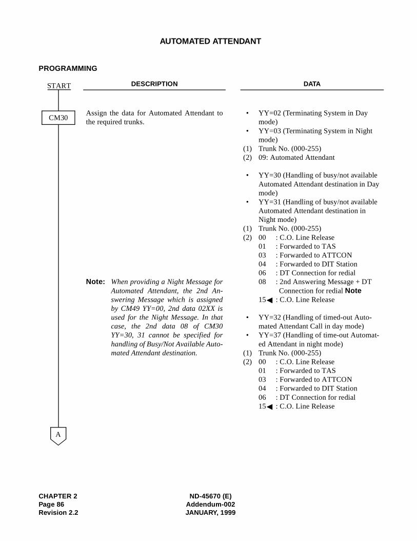
AUTOMATED ATTENDANT
PROGRAMMING
DESCRIPTION DATA
Assign the data for Automated Attendant tothe required trunks.
Note: When providing a Night Message forAutomated Attendant, the 2nd An-swering Message which is assignedby CM49 YY=00, 2nd data 02XX isused for the Night Message. In thatcase, the 2nd data 08 of CM30YY=30, 31 cannot be specified forhandling of Busy/Not Available Auto-mated Attendant destination.
• YY=02 (Terminating System in Day mode)
• YY=03 (Terminating System in Night mode)
(1) Trunk No. (000-255)(2) 09: Automated Attendant
• YY=30 (Handling of busy/not available Automated Attendant destination in Daymode)
• YY=31 (Handling of busy/not available Automated Attendant destination in Night mode)
(1) Trunk No. (000-255)(2) 00 : C.O. Line Release
01 : Forwarded to TAS03 : Forwarded to ATTCON04 : Forwarded to DIT Station06 : DT Connection for redial08 : 2nd Answering Message + DT
Connection for redial Note15 : C.O. Line Release
• YY=32 (Handling of timed-out Auto-mated Attendant Call in day mode)
• YY=37 (Handling of time-out Automat-ed Attendant in night mode)
(1) Trunk No. (000-255)(2) 00 : C.O. Line Release
01 : Forwarded to TAS03 : Forwarded to ATTCON04 : Forwarded to DIT Station06 : DT Connection for redial15 : C.O. Line Release
CM30
START
A
CHAPTER 2 ND-45670 (E)Page 86 Addendum-002Revision 2.2 JANUARY, 1999
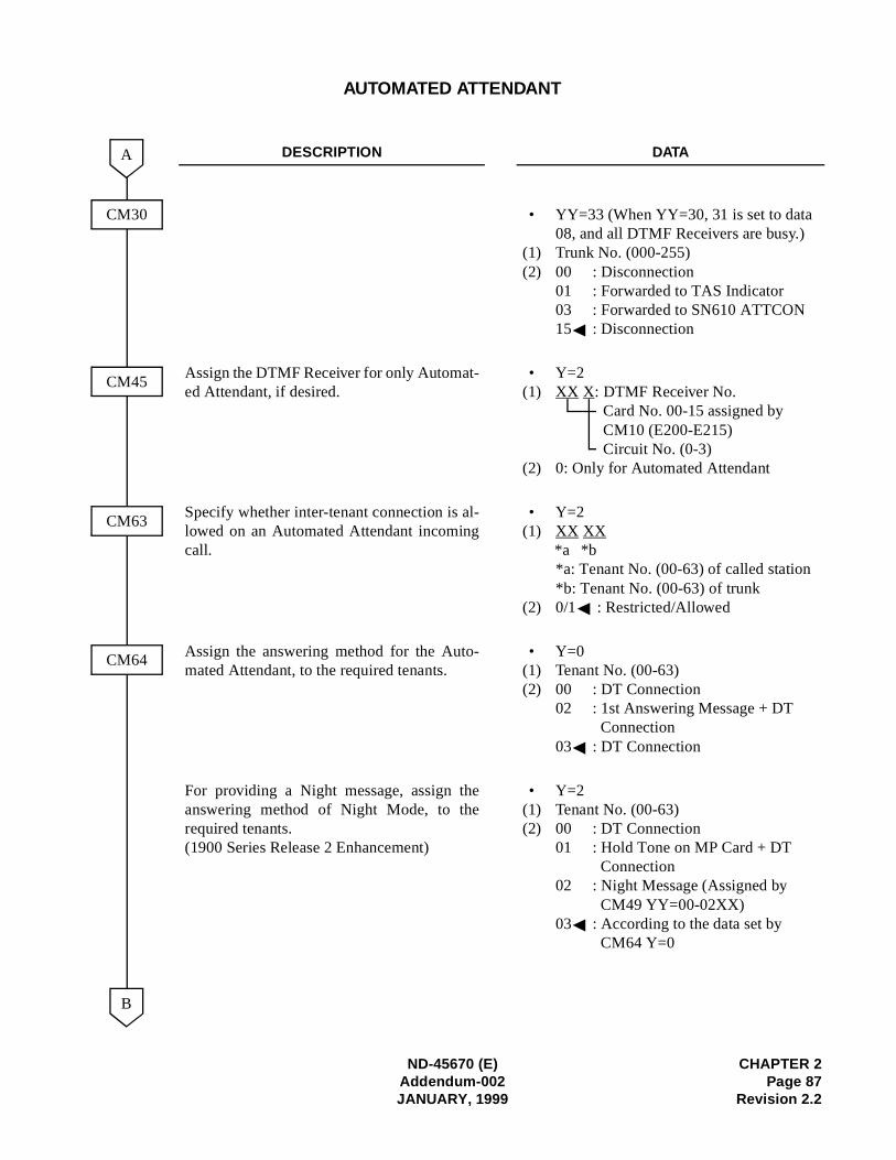
AUTOMATED ATTENDANT
DESCRIPTION DATA
• YY=33 (When YY=30, 31 is set to data08, and all DTMF Receivers are busy.)
(1) Trunk No. (000-255)(2) 00 : Disconnection
01 : Forwarded to TAS Indicator03 : Forwarded to SN610 ATTCON15 : Disconnection
Assign the DTMF Receiver for only Automat-ed Attendant, if desired.
• Y=2(1) XX X: DTMF Receiver No.
Card No. 00-15 assigned by CM10 (E200-E215)Circuit No. (0-3)
(2) 0: Only for Automated Attendant
Specify whether inter-tenant connection is al-lowed on an Automated Attendant incomingcall.
• Y=2(1) XX XX
*a: Tenant No. (00-63) of called station*b: Tenant No. (00-63) of trunk
(2) 0/1 : Restricted/Allowed
Assign the answering method for the Auto-mated Attendant, to the required tenants.
• Y=0(1) Tenant No. (00-63)(2) 00 : DT Connection
02 : 1st Answering Message + DT Connection
03 : DT Connection
For providing a Night message, assign theanswering method of Night Mode, to therequired tenants.(1900 Series Release 2 Enhancement)
• Y=2(1) Tenant No. (00-63)(2) 00 : DT Connection
01 : Hold Tone on MP Card + DT Connection
02 : Night Message (Assigned by CM49 YY=00-02XX)
03 : According to the data set by CM64 Y=0
A
CM45
CM63
CM64
CM30
*b*a
B
ND-45670 (E) CHAPTER 2Addendum-002 Page 87JANUARY, 1999 Revision 2.2
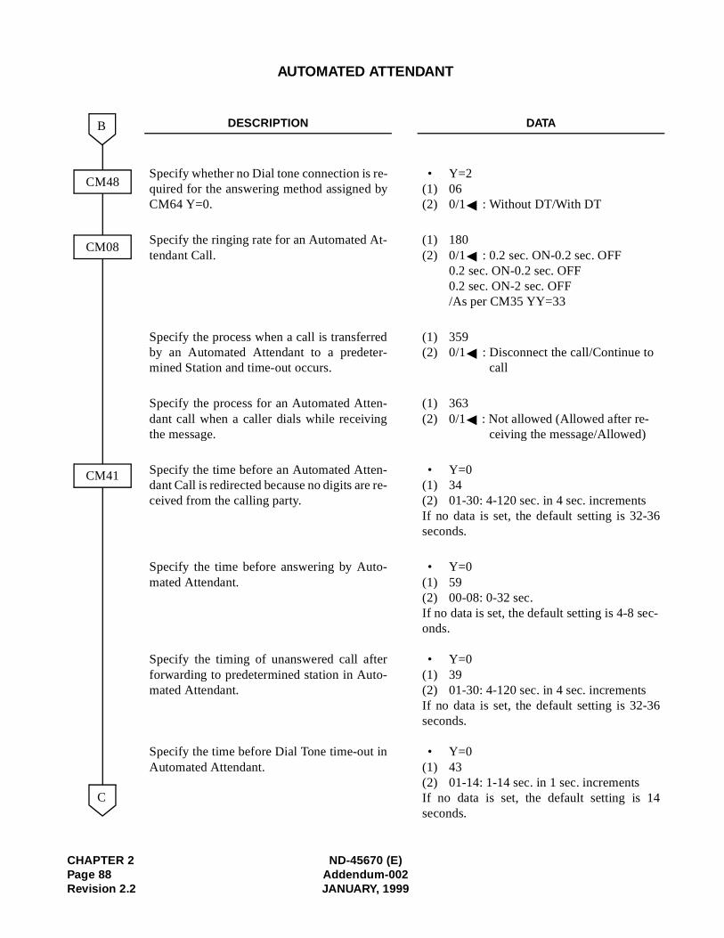
CHAPTER 2 ND-45670 (E)Page 88 Addendum-002Revision 2.2 JANUARY, 1999
AUTOMATED ATTENDANT
DESCRIPTION DATA
Specify whether no Dial tone connection is re-quired for the answering method assigned byCM64 Y=0.
• Y=2(1) 06(2) 0/1 : Without DT/With DT
Specify the ringing rate for an Automated At-tendant Call.
(1) 180(2) 0/1 : 0.2 sec. ON-0.2 sec. OFF
0.2 sec. ON-0.2 sec. OFF0.2 sec. ON-2 sec. OFF/As per CM35 YY=33
Specify the process when a call is transferredby an Automated Attendant to a predeter-mined Station and time-out occurs.
(1) 359(2) 0/1 : Disconnect the call/Continue to
call
Specify the process for an Automated Atten-dant call when a caller dials while receivingthe message.
(1) 363(2) 0/1 : Not allowed (Allowed after re-
ceiving the message/Allowed)
Specify the time before an Automated Atten-dant Call is redirected because no digits are re-ceived from the calling party.
• Y=0(1) 34(2) 01-30: 4-120 sec. in 4 sec. incrementsIf no data is set, the default setting is 32-36seconds.
Specify the time before answering by Auto-mated Attendant.
Specify the timing of unanswered call afterforwarding to predetermined station in Auto-mated Attendant.
Specify the time before Dial Tone time-out inAutomated Attendant.
• Y=0(1) 59(2) 00-08: 0-32 sec.If no data is set, the default setting is 4-8 sec-onds.
• Y=0(1) 39(2) 01-30: 4-120 sec. in 4 sec. incrementsIf no data is set, the default setting is 32-36seconds.
• Y=0(1) 43(2) 01-14: 1-14 sec. in 1 sec. incrementsIf no data is set, the default setting is 14seconds.
CM41
CM08
C
CM48
B
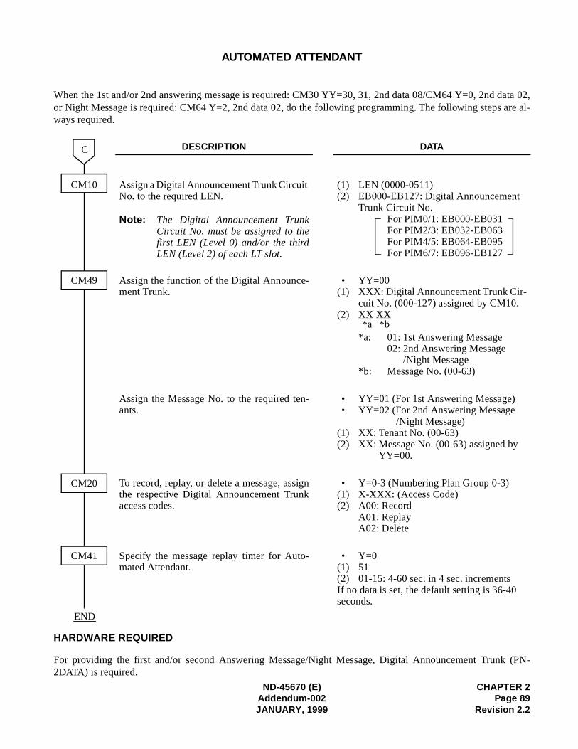
data 02, are al-
k (PN-
AUTOMATED ATTENDANT
When the 1st and/or 2nd answering message is required: CM30 YY=30, 31, 2nd data 08/CM64 Y=0, 2ndor Night Message is required: CM64 Y=2, 2nd data 02, do the following programming. The following stepsways required.
HARDWARE REQUIRED
For providing the first and/or second Answering Message/Night Message, Digital Announcement Trun
DESCRIPTION DATA
Assign a Digital Announcement Trunk Circuit No. to the required LEN.
Note: The Digital Announcement TrunkCircuit No. must be assigned to thefirst LEN (Level 0) and/or the thirdLEN (Level 2) of each LT slot.
(1) LEN (0000-0511)(2) EB000-EB127: Digital Announcement
Trunk Circuit No.For PIM0/1: EB000-EB031For PIM2/3: EB032-EB063For PIM4/5: EB064-EB095For PIM6/7: EB096-EB127
Assign the function of the Digital Announce-ment Trunk.
• YY=00(1) XXX: Digital Announcement Trunk Cir-
cuit No. (000-127) assigned by CM10.(2) XX XX
*a: 01: 1st Answering Message02: 2nd Answering Message
/Night Message*b: Message No. (00-63)
Assign the Message No. to the required ten-ants.
• YY=01 (For 1st Answering Message)• YY=02 (For 2nd Answering Message
/Night Message)(1) XX: Tenant No. (00-63)(2) XX: Message No. (00-63) assigned by
YY=00.
To record, replay, or delete a message, assignthe respective Digital Announcement Trunkaccess codes.
• Y=0-3 (Numbering Plan Group 0-3)(1) X-XXX: (Access Code)(2) A00: Record
A01: ReplayA02: Delete
Specify the message replay timer for Auto-mated Attendant.
• Y=0(1) 51(2) 01-15: 4-60 sec. in 4 sec. incrementsIf no data is set, the default setting is 36-40 seconds.
CM10
CM49
CM20
CM41
C
END
*b*a
ND-45670 (E) CHAPTER 2Addendum-002 Page 89JANUARY, 1999 Revision 2.2
2DATA) is required.
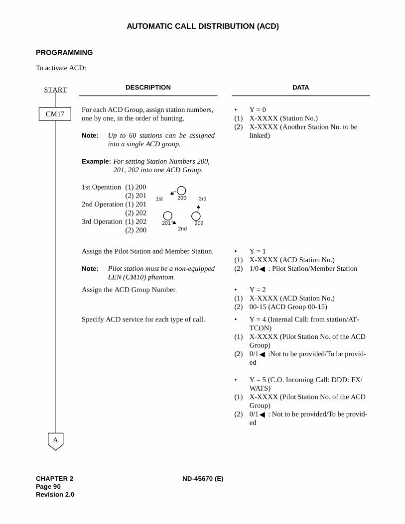
AUTOMATIC CALL DISTRIBUTION (ACD)
PROGRAMMING
To activate ACD:
DESCRIPTION DATA
For each ACD Group, assign station numbers, one by one, in the order of hunting.
Note: Up to 60 stations can be assignedinto a single ACD group.
Example: For setting Station Numbers 200, 201, 202 into one ACD Group.
1st Operation (1) 200 (2) 201
2nd Operation (1) 201(2) 202
3rd Operation (1) 202(2) 200
• Y = 0(1) X-XXXX (Station No.)(2) X-XXXX (Another Station No. to be
linked)
Assign the Pilot Station and Member Station.
Note: Pilot station must be a non-equippedLEN (CM10) phantom.
• Y = 1(1) X-XXXX (ACD Station No.)(2) 1/0 : Pilot Station/Member Station
Assign the ACD Group Number. • Y = 2(1) X-XXXX (ACD Station No.)(2) 00-15 (ACD Group 00-15)
Specify ACD service for each type of call. • Y = 4 (Internal Call: from station/AT-TCON)
(1) X-XXXX (Pilot Station No. of the ACD Group)
(2) 0/1 :Not to be provided/To be provid-ed
• Y = 5 (C.O. Incoming Call: DDD: FX/WATS)
(1) X-XXXX (Pilot Station No. of the ACD Group)
(2) 0/1 : Not to be provided/To be provid-ed
CM17
START
A
3rd1st
2nd
200
202201
CHAPTER 2 ND-45670 (E)Page 90Revision 2.0
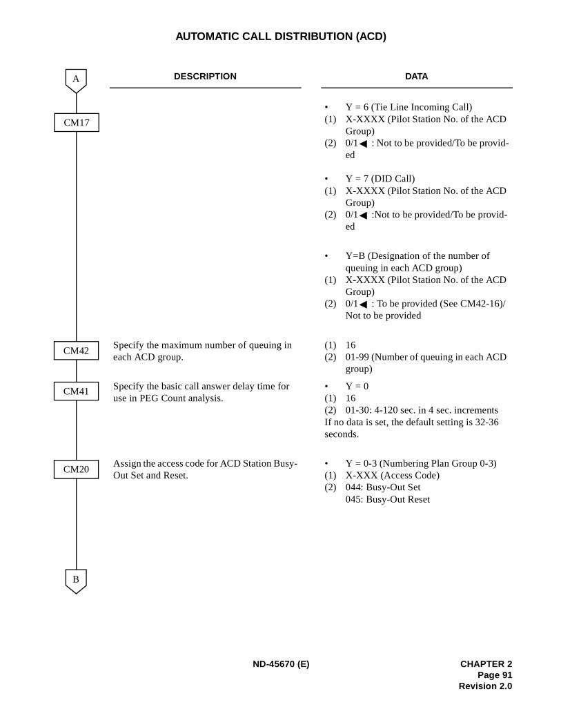
AUTOMATIC CALL DISTRIBUTION (ACD)
DESCRIPTION DATA
• Y = 6 (Tie Line Incoming Call)(1) X-XXXX (Pilot Station No. of the ACD
Group)(2) 0/1 : Not to be provided/To be provid-
ed
• Y = 7 (DID Call)(1) X-XXXX (Pilot Station No. of the ACD
Group)(2) 0/1 :Not to be provided/To be provid-
ed
• Y=B (Designation of the number of queuing in each ACD group)
(1) X-XXXX (Pilot Station No. of the ACD Group)
(2) 0/1 : To be provided (See CM42-16)/Not to be provided
Specify the maximum number of queuing in each ACD group.
(1) 16(2) 01-99 (Number of queuing in each ACD
group)
Specify the basic call answer delay time for use in PEG Count analysis.
• Y = 0(1) 16(2) 01-30: 4-120 sec. in 4 sec. incrementsIf no data is set, the default setting is 32-36 seconds.
Assign the access code for ACD Station Busy-Out Set and Reset.
• Y = 0-3 (Numbering Plan Group 0-3)(1) X-XXX (Access Code)(2) 044: Busy-Out Set
045: Busy-Out Reset
CM41
A
B
CM20
CM42
CM17
ND-45670 (E) CHAPTER 2Page 91
Revision 2.0
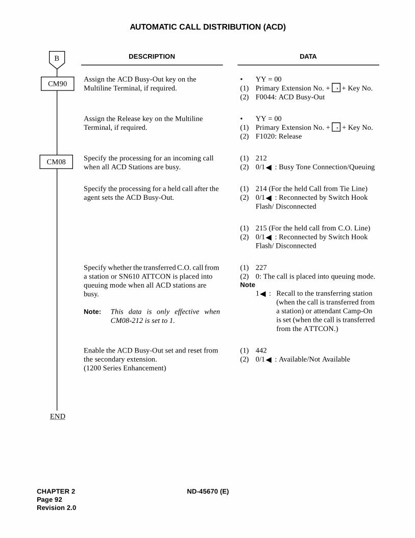
.
AUTOMATIC CALL DISTRIBUTION (ACD)
DESCRIPTION DATA
Assign the ACD Busy-Out key on the Multiline Terminal, if required.
• YY = 00(1) Primary Extension No. + + Key No.(2) F0044: ACD Busy-Out
Assign the Release key on the Multiline Terminal, if required.
• YY = 00(1) Primary Extension No. + + Key No.(2) F1020: Release
Specify the processing for an incoming call when all ACD Stations are busy.
(1) 212(2) 0/1 : Busy Tone Connection/Queuing
Specify the processing for a held call after the agent sets the ACD Busy-Out.
(1) 214 (For the held Call from Tie Line)(2) 0/1 : Reconnected by Switch Hook
Flash/ Disconnected
(1) 215 (For the held call from C.O. Line)(2) 0/1 : Reconnected by Switch Hook
Flash/ Disconnected
Specify whether the transferred C.O. call from a station or SN610 ATTCON is placed into queuing mode when all ACD stations are busy.
Note: This data is only effective whenCM08-212 is set to 1.
(1) 227(2) 0: The call is placed into queuing modeNote
1 : Recall to the transferring station (when the call is transferred from a station) or attendant Camp-On is set (when the call is transferredfrom the ATTCON.)
Enable the ACD Busy-Out set and reset from the secondary extension. (1200 Series Enhancement)
(1) 442(2) 0/1 : Available/Not Available
END
B
CM90
CM08
,
,
CHAPTER 2 ND-45670 (E)Page 92Revision 2.0
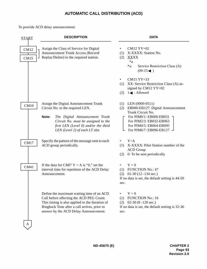
AUTOMATIC CALL DISTRIBUTION (ACD)
To provide ACD delay announcement:
DESCRIPTION DATA
Assign the Class of Service for Digital Announcement Trunk Access (Record/Replay/Delete) to the required station.
• CM12 YY=02(1) X-XXXX: Station No.(2) XXXX
*a *a: Service Restriction Class (A)
(00-15 )
• CM15 YY=33(1) XX: Service Restriction Class (A) as-
signed by CM12 YY=02(2) 1 : Allowed
Assign the Digital Announcement Trunk Circuit No. to the required LEN.
Note: The Digital Announcement TrunkCircuit No. must be assigned to thefirst LEN (Level 0) and/or the thirdLEN (Level 2) of each LT slot.
(1) LEN (0000-0511)(2) EB000-EB127: Digital Announcement
Trunk Circuit No.For PIM0/1: EB000-EB031For PIM2/3: EB032-EB063For PIM4/5: EB064-EB095For PIM6/7: EB096-EB127
Specify the pattern of the message sent to each ACD group periodically.
• Y=A(1) X-XXXX: Pilot Station number of the
ACD Group(2) 0: To be sent periodically
If the data for CMl7 Y = A is “0,” set the interval time for repetition of the ACD Delay Announcement.
• Y = 0(1) FUNCTION No.: 47(2) 01-30 (12 -134 sec.)If no data is set, the default setting is 44-50 sec.
Define the maximum waiting time of an ACD Call before affecting the ACD PEG Count. This timing is also applied to the duration of Ringback Tone after a call arrives, prior to answer by the ACD Delay Announcement.
• Y = 0(1) FUNCTION No.: 16(2) 02-30 (8 -120 sec.)If no data is set, the default setting is 32-36 sec.
CM41
CM12
CM15
A
START
CM10
CM17
ND-45670 (E) CHAPTER 2Page 93
Revision 2.0
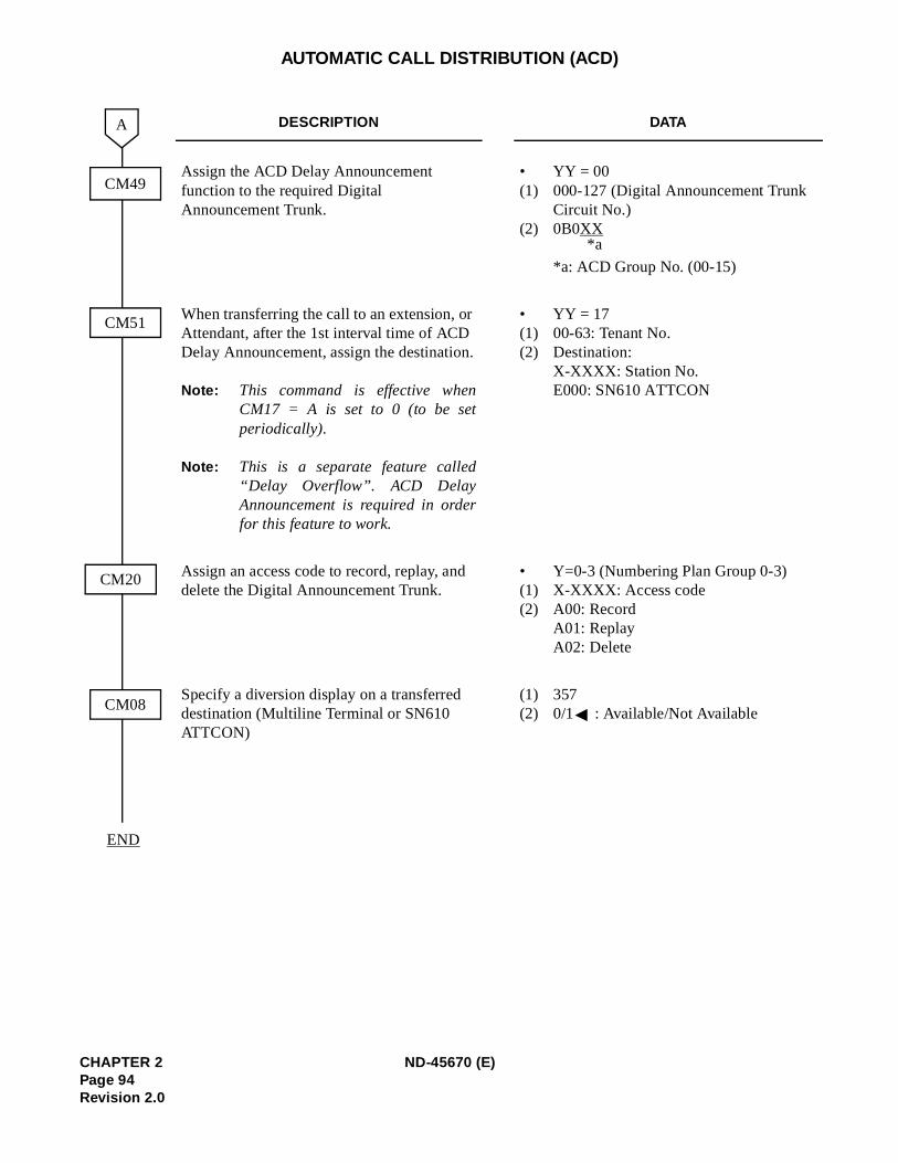
AUTOMATIC CALL DISTRIBUTION (ACD)
DESCRIPTION DATA
Assign the ACD Delay Announcement function to the required Digital Announcement Trunk.
• YY = 00(1) 000-127 (Digital Announcement Trunk
Circuit No.)(2) 0B0XX
*a: ACD Group No. (00-15)
When transferring the call to an extension, or Attendant, after the 1st interval time of ACD Delay Announcement, assign the destination.
Note: This command is effective whenCM17 = A is set to 0 (to be setperiodically).
Note: This is a separate feature called“Delay Overflow”. ACD DelayAnnouncement is required in orderfor this feature to work.
• YY = 17(1) 00-63: Tenant No. (2) Destination:
X-XXXX: Station No. E000: SN610 ATTCON
Assign an access code to record, replay, and delete the Digital Announcement Trunk.
• Y=0-3 (Numbering Plan Group 0-3)(1) X-XXXX: Access code(2) A00: Record
A01: ReplayA02: Delete
Specify a diversion display on a transferred destination (Multiline Terminal or SN610 ATTCON)
(1) 357(2) 0/1 : Available/Not Available
A
END
CM20
CM08
CM49
CM51
*a
CHAPTER 2 ND-45670 (E)Page 94Revision 2.0
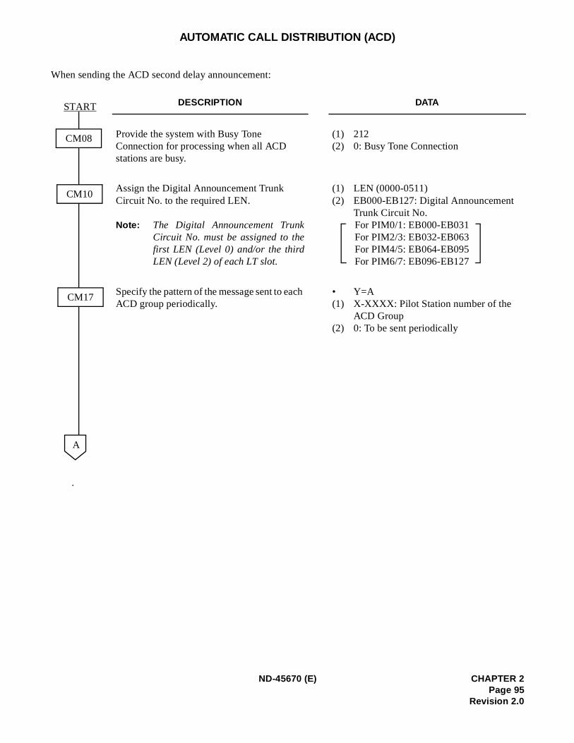
AUTOMATIC CALL DISTRIBUTION (ACD)
When sending the ACD second delay announcement:
.
DESCRIPTION DATA
Provide the system with Busy Tone Connection for processing when all ACD stations are busy.
(1) 212(2) 0: Busy Tone Connection
Assign the Digital Announcement Trunk Circuit No. to the required LEN.
Note: The Digital Announcement TrunkCircuit No. must be assigned to thefirst LEN (Level 0) and/or the thirdLEN (Level 2) of each LT slot.
(1) LEN (0000-0511)(2) EB000-EB127: Digital Announcement
Trunk Circuit No.For PIM0/1: EB000-EB031For PIM2/3: EB032-EB063For PIM4/5: EB064-EB095For PIM6/7: EB096-EB127
Specify the pattern of the message sent to each ACD group periodically.
• Y=A(1) X-XXXX: Pilot Station number of the
ACD Group(2) 0: To be sent periodically
CM08
START
A
CM10
CM17
ND-45670 (E) CHAPTER 2Page 95
Revision 2.0
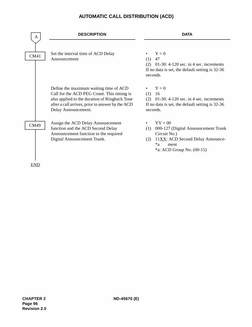
AUTOMATIC CALL DISTRIBUTION (ACD)
DESCRIPTION DATA
Set the interval time of ACD Delay Announcement
• Y = 0(1) 47(2) 01-30: 4-120 sec. in 4 sec. incrementsIf no data is set, the default setting is 32-36 seconds.
Define the maximum waiting time of ACD Call for the ACD PEG Count. This timing is also applied to the duration of Ringback Tone after a call arrives, prior to answer by the ACD Delay Announcement.
• Y = 0(1) 16(2) 01-30: 4-120 sec. in 4 sec. incrementsIf no data is set, the default setting is 32-36 seconds.
Assign the ACD Delay Announcement function and the ACD Second Delay Announcement function to the required Digital Announcement Trunk.
• YY = 00(1) 000-127 (Digital Announcement Trunk
Circuit No.)(2) 11XX: ACD Second Delay Announce-
*a ment*a: ACD Group No. (00-15)
CM49
END
A
CM41
CHAPTER 2 ND-45670 (E)Page 96Revision 2.0
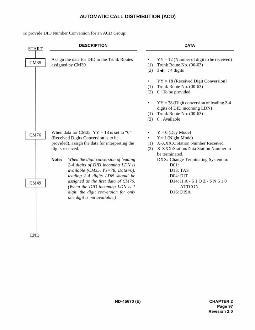
AUTOMATIC CALL DISTRIBUTION (ACD)
To provide DID Number Conversion for an ACD Group:
DESCRIPTION DATA
Assign the data for DID to the Trunk Routes assigned by CM30
• YY = 12 (Number of digit to be received)(1) Trunk Route No. (00-63)(2) 3 : 4 digits
• YY = 18 (Received Digit Conversion)(1) Trunk Route No. (00-63)(2) 0 : To be provided
• YY = 78 (Digit conversion of leading 2-4 digits of DID incoming LDN)
(1) Trunk Route No. (00-63)(2) 0 : Available
When data for CM35, YY = 18 is set to “0” (Received Digits Conversion is to be provided), assign the data for interpreting the digits received.
Note: When the digit conversion of leading2-4 digits of DID incoming LDN isavailable (CM35, YY=78, Data=0),leading 2-4 digits LDN should beassigned as the first data of CM76.(When the DID incoming LDN is 1digit, the digit conversion for onlyone digit is not available.)
• Y = 0 (Day Mode)• Y= 1 (Night Mode)(1) X-XXXX:Station Number Received(2) X-XXX:Station/Data Station Number to
be terminated.DXX: Change Terminating System to:
D01:D13: TASD04: DITD14: H A - 6 1 O Z / S N 6 1 0
ATTCOND16: DISA
START
END
CM35
CM76
CM49
ND-45670 (E) CHAPTER 2Page 97
Revision 2.0
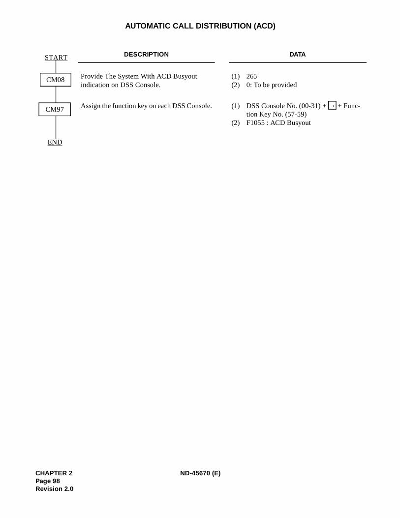
nc-
AUTOMATIC CALL DISTRIBUTION (ACD)
DESCRIPTION DATA
Provide The System With ACD Busyout indication on DSS Console.
(1) 265(2) 0: To be provided
Assign the function key on each DSS Console. (1) DSS Console No. (00-31) + + Fution Key No. (57-59)
(2) F1055 : ACD Busyout
START
END
CM08
CM97,
CHAPTER 2 ND-45670 (E)Page 98Revision 2.0
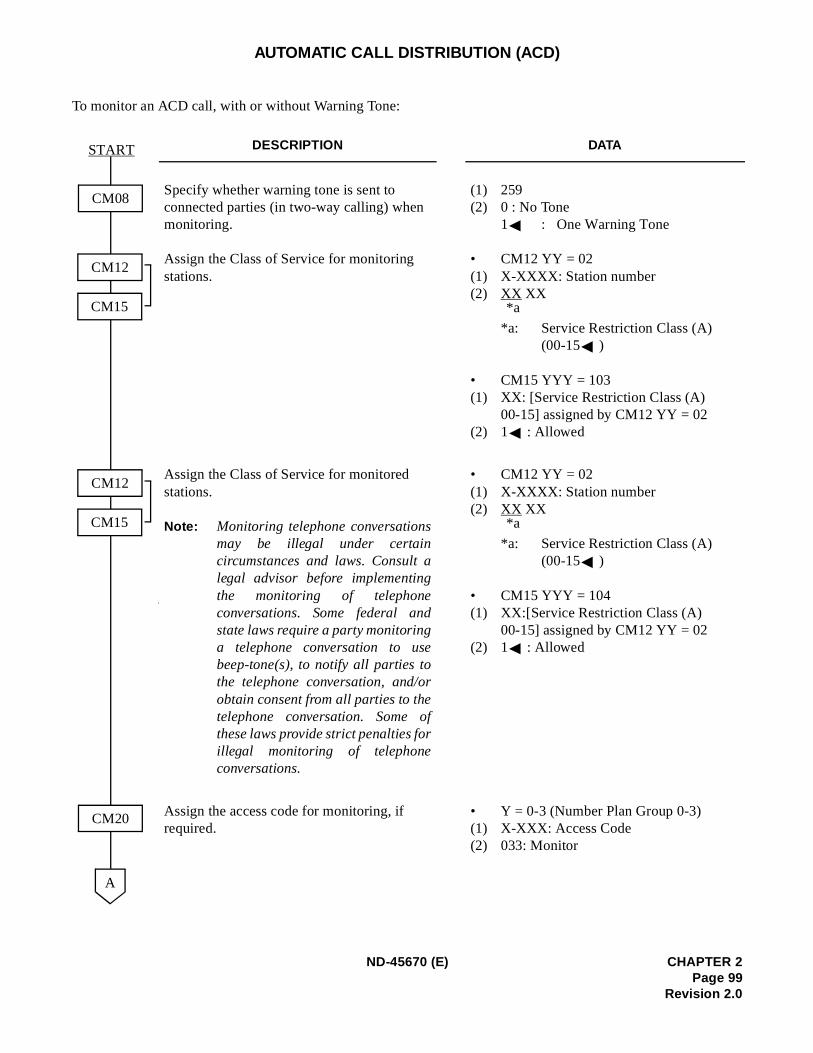
AUTOMATIC CALL DISTRIBUTION (ACD)
To monitor an ACD call, with or without Warning Tone:
DESCRIPTION DATA
Specify whether warning tone is sent to connected parties (in two-way calling) when monitoring.
Assign the Class of Service for monitoring stations.
(1) 259(2) 0 : No Tone
1 : One Warning Tone
• CM12 YY = 02(1) X-XXXX: Station number(2) XX XX
*a: Service Restriction Class (A) (00-15 )
• CM15 YYY = 103(1) XX: [Service Restriction Class (A)
00-15] assigned by CM12 YY = 02(2) 1 : Allowed
Assign the Class of Service for monitored stations.
Note: Monitoring telephone conversationsmay be illegal under certaincircumstances and laws. Consult alegal advisor before implementingthe monitoring of telephoneconversations. Some federal andstate laws require a party monitoringa telephone conversation to usebeep-tone(s), to notify all parties tothe telephone conversation, and/orobtain consent from all parties to thetelephone conversation. Some ofthese laws provide strict penalties forillegal monitoring of telephoneconversations.
• CM12 YY = 02(1) X-XXXX: Station number(2) XX XX
*a: Service Restriction Class (A) (00-15 )
• CM15 YYY = 104(1) XX:[Service Restriction Class (A)
00-15] assigned by CM12 YY = 02(2) 1 : Allowed
Assign the access code for monitoring, if required.
• Y = 0-3 (Number Plan Group 0-3)(1) X-XXX: Access Code(2) 033: Monitor
CM08
START
CM20
A
CM12
CM15
CM12
CM15
*a
*a
ND-45670 (E) CHAPTER 2Page 99
Revision 2.0
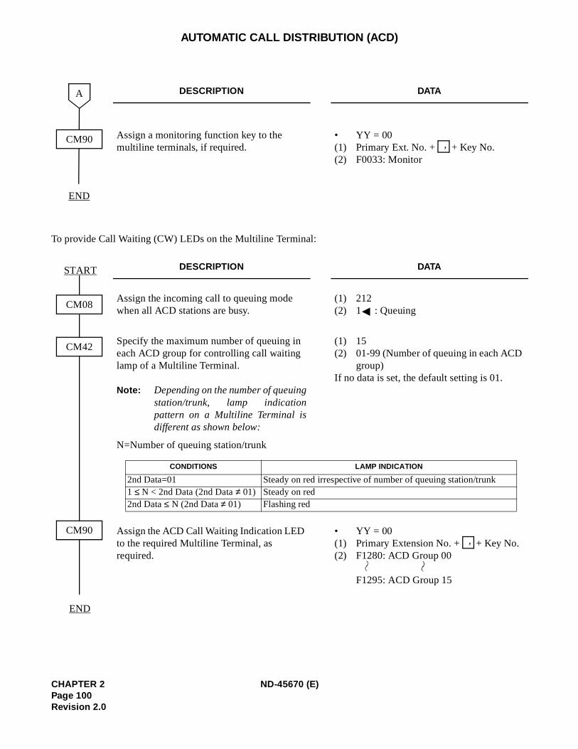
AUTOMATIC CALL DISTRIBUTION (ACD)
To provide Call Waiting (CW) LEDs on the Multiline Terminal:
DESCRIPTION DATA
Assign a monitoring function key to the multiline terminals, if required.
• YY = 00(1) Primary Ext. No. + + Key No.(2) F0033: Monitor
DESCRIPTION DATA
Assign the incoming call to queuing mode when all ACD stations are busy.
(1) 212(2) 1 : Queuing
Specify the maximum number of queuing in each ACD group for controlling call waiting lamp of a Multiline Terminal.
Note: Depending on the number of queuingstation/trunk, lamp indicationpattern on a Multiline Terminal isdifferent as shown below:
(1) 15(2) 01-99 (Number of queuing in each ACD
group)If no data is set, the default setting is 01.
N=Number of queuing station/trunk
Assign the ACD Call Waiting Indication LED to the required Multiline Terminal, as required.
• YY = 00(1) Primary Extension No. + + Key No. (2) F1280: ACD Group 00
F1295: ACD Group 15
CM90
END
A
,
CM08
END
START
CM42
CM90
CONDITIONS LAMP INDICATION
2nd Data=01 Steady on red irrespective of number of queuing station/trunk1 ≤ N < 2nd Data (2nd Data ≠ 01) Steady on red2nd Data ≤ N (2nd Data ≠ 01) Flashing red
,
CHAPTER 2 ND-45670 (E)Page 100Revision 2.0
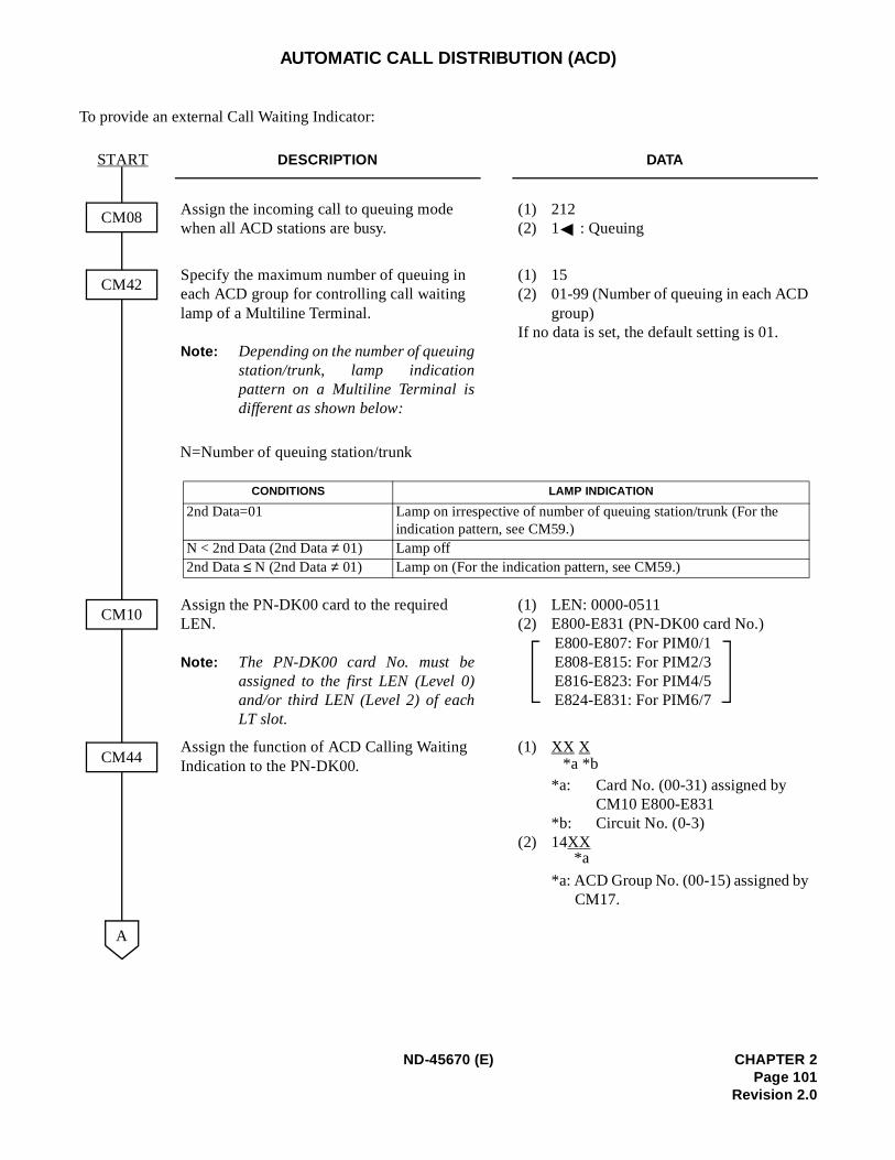
AUTOMATIC CALL DISTRIBUTION (ACD)
To provide an external Call Waiting Indicator:
DESCRIPTION DATA
Assign the incoming call to queuing mode when all ACD stations are busy.
(1) 212(2) 1 : Queuing
Specify the maximum number of queuing in each ACD group for controlling call waiting lamp of a Multiline Terminal.
Note: Depending on the number of queuingstation/trunk, lamp indicationpattern on a Multiline Terminal isdifferent as shown below:
(1) 15(2) 01-99 (Number of queuing in each ACD
group)If no data is set, the default setting is 01.
Assign the PN-DK00 card to the required LEN.
Note: The PN-DK00 card No. must beassigned to the first LEN (Level 0)and/or third LEN (Level 2) of eachLT slot.
(1) LEN: 0000-0511(2) E800-E831 (PN-DK00 card No.)
E800-E807: For PIM0/1E808-E815: For PIM2/3E816-E823: For PIM4/5E824-E831: For PIM6/7
Assign the function of ACD Calling Waiting Indication to the PN-DK00.
(1) XX X
*a: Card No. (00-31) assigned by CM10 E800-E831
*b: Circuit No. (0-3)(2) 14XX
*a: ACD Group No. (00-15) assigned by CM17.
CM10
START
CM44
CM08
CM42
A
N=Number of queuing station/trunk
CONDITIONS LAMP INDICATION
2nd Data=01 Lamp on irrespective of number of queuing station/trunk (For the indication pattern, see CM59.)
N < 2nd Data (2nd Data ≠ 01) Lamp off2nd Data ≤ N (2nd Data ≠ 01) Lamp on (For the indication pattern, see CM59.)
*b*a
*a
ND-45670 (E) CHAPTER 2Page 101
Revision 2.0
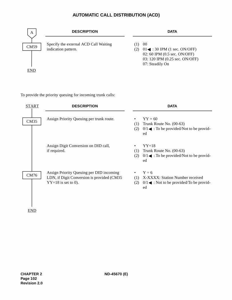
AUTOMATIC CALL DISTRIBUTION (ACD)
To provide the priority queuing for incoming trunk calls:
DESCRIPTION DATA
Specify the external ACD Call Waiting indication pattern.
(1) 00(2) 01 : 30 IPM (1 sec. ON/OFF)
02: 60 IPM (0.5 sec. ON/OFF)03: 120 IPM (0.25 sec. ON/OFF)07: Steadily On
DESCRIPTION DATA
Assign Priority Queuing per trunk route. • YY = 60(1) Trunk Route No. (00-63)(2) 0/1 : To be provided/Not to be provid-
ed
Assign Digit Conversion on DID call, if required.
• YY=18(1) Trunk Route No. (00-63)(2) 0/1 : To be provided/Not to be provid-
ed
Assign Priority Queuing per DID incoming LDN, if Digit Conversion is provided (CM35 YY=18 is set to 0).
• Y = 6(1) X-XXXX: Station Number received(2) 0/1 : Not to be provided/To be provid-
ed
CM59
END
A
CM35
END
CM76
START
CHAPTER 2 ND-45670 (E)Page 102Revision 2.0
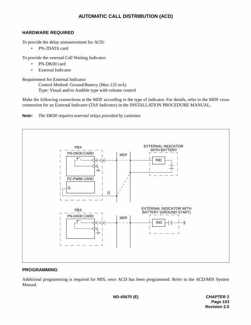
cross
ystem
AUTOMATIC CALL DISTRIBUTION (ACD)
HARDWARE REQUIRED
To provide the delay announcement for ACD:
• PN-2DATA card
To provide the external Call Waiting Indicator:
• PN-DK00 card• External Indicator
Requirement for External IndicatorControl Method: Ground/Battery (Max.125 mA)Type: Visual and/or Audible type with volume control
Make the following connections at the MDF according to the type of indicator. For details, refer to the MDFconnection for an External Indicator (TAS Indicator) in the INSTALLATION PROCEDURE MANUAL.
Note: The DK00 requires external relays provided by customer.
PROGRAMMING
Additional programming is required for MIS, once ACD has been programmed. Refer to the ACD/MIS SManual.
PBX
PN-DK00 CARD
PZ-PW86 CARD
G
PBX
PN-DK00 CARD
MDF
MDF
EXTERNAL INDICATORWITH BATTERY
EXTERNAL INDICATOR WITHBATTERY (GROUND START)
IND
IND
G
ND-45670 (E) CHAPTER 2Page 103
Revision 2.0
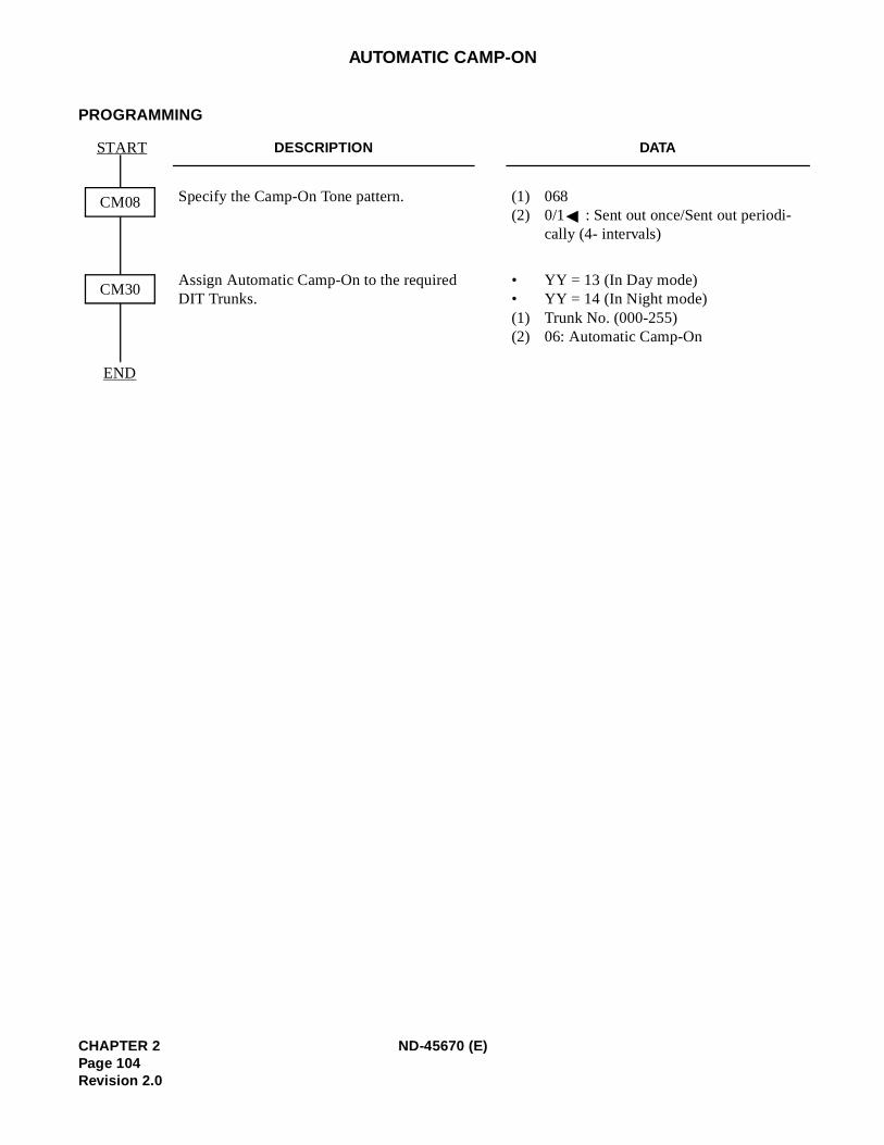
AUTOMATIC CAMP-ON
PROGRAMMING
DESCRIPTION DATA
Specify the Camp-On Tone pattern. (1) 068(2) 0/1 : Sent out once/Sent out periodi-
cally (4- intervals)
Assign Automatic Camp-On to the required DIT Trunks.
• YY = 13 (In Day mode)• YY = 14 (In Night mode)(1) Trunk No. (000-255)(2) 06: Automatic Camp-On
CM08
START
END
CM30
CHAPTER 2 ND-45670 (E)Page 104Revision 2.0
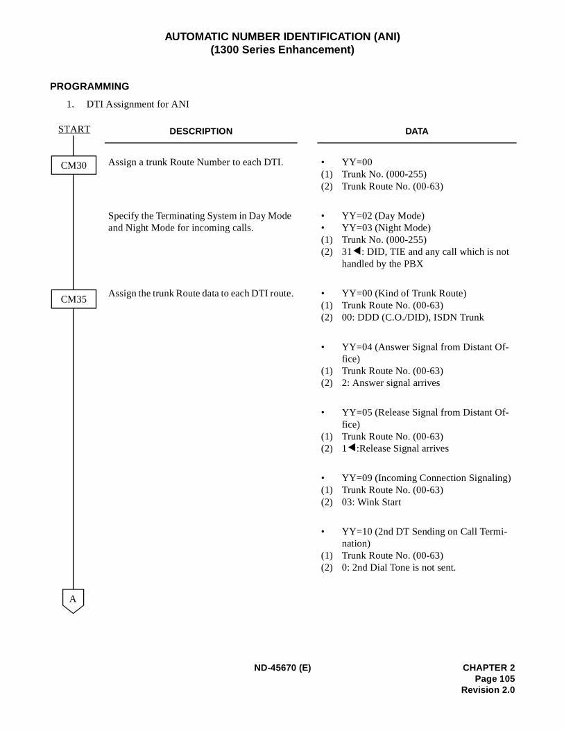
AUTOMATIC NUMBER IDENTIFICATION (ANI) (1300 Series Enhancement)
PROGRAMMING
1. DTI Assignment for ANI
DESCRIPTION DATA
Assign a trunk Route Number to each DTI. • YY=00 (1) Trunk No. (000-255) (2) Trunk Route No. (00-63)
Specify the Terminating System in Day Mode and Night Mode for incoming calls.
• YY=02 (Day Mode) • YY=03 (Night Mode) (1) Trunk No. (000-255) (2) 31 : DID, TIE and any call which is not
handled by the PBX
Assign the trunk Route data to each DTI route. • YY=00 (Kind of Trunk Route) (1) Trunk Route No. (00-63) (2) 00: DDD (C.O./DID), ISDN Trunk
• YY=04 (Answer Signal from Distant Of-fice)
(1) Trunk Route No. (00-63) (2) 2: Answer signal arrives
• YY=05 (Release Signal from Distant Of-fice)
(1) Trunk Route No. (00-63) (2) 1 :Release Signal arrives
• YY=09 (Incoming Connection Signaling)(1) Trunk Route No. (00-63) (2) 03: Wink Start
• YY=10 (2nd DT Sending on Call Termi-nation)
(1) Trunk Route No. (00-63) (2) 0: 2nd Dial Tone is not sent.
A
CM35
CM30
START
ND-45670 (E) CHAPTER 2Page 105
Revision 2.0
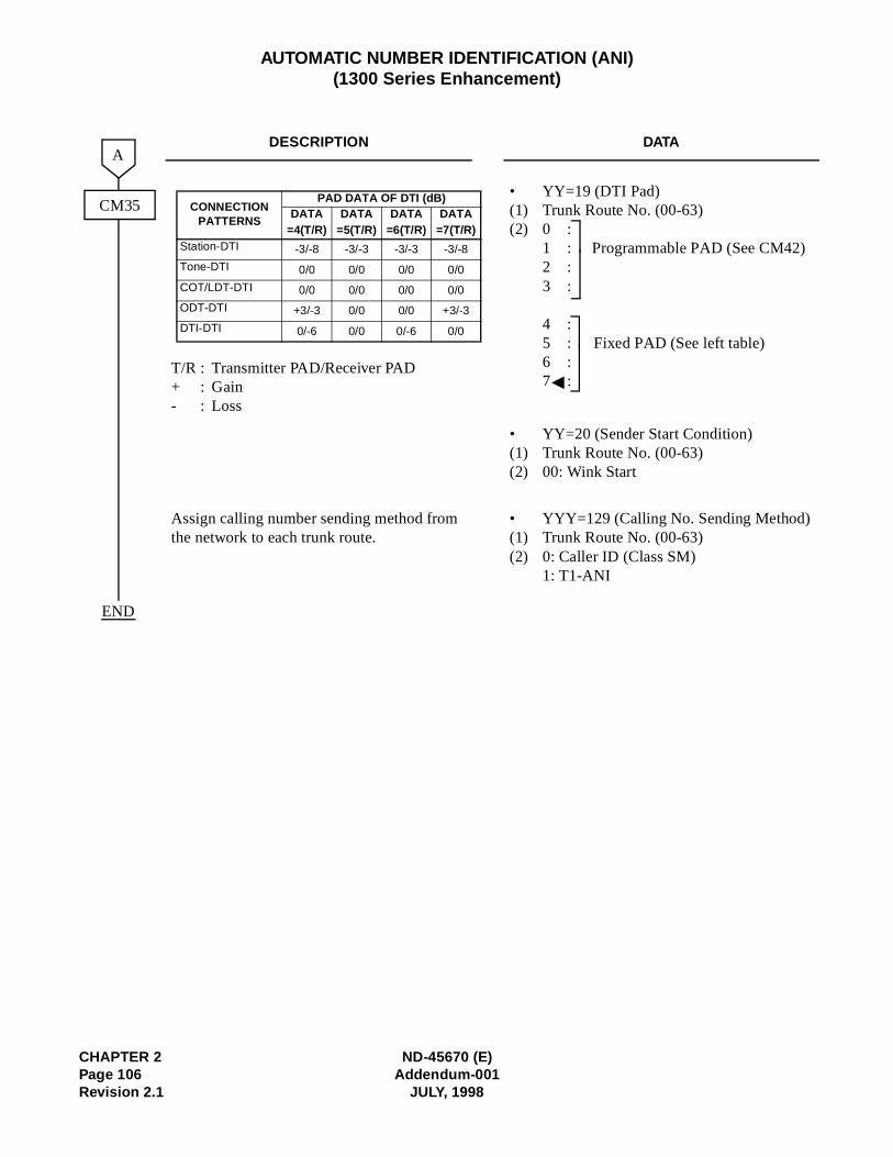
CHAPTER 2 ND-45670 (E)Page 106 Addendum-001Revision 2.1 JULY, 1998
AUTOMATIC NUMBER IDENTIFICATION (ANI)(1300 Series Enhancement)
DESCRIPTION DATA
T/R : Transmitter PAD/Receiver PAD+ : Gain- : Loss
• YY=19 (DTI Pad) (1) Trunk Route No. (00-63) (2) 0 :
1 : Programmable PAD (See CM42)2 : 3 :
4 : 5 : Fixed PAD (See left table) 6 :7 :
• YY=20 (Sender Start Condition) (1) Trunk Route No. (00-63) (2) 00: Wink Start
Assign calling number sending method from the network to each trunk route.
• YYY=129 (Calling No. Sending Method)(1) Trunk Route No. (00-63)(2) 0: Caller ID (Class SM)
1: T1-ANI
A
CM35
END
CONNECTION PATTERNS
PAD DATA OF DTI (dB)DATA DATA DATA DATA
=4(T/R) =5(T/R) =6(T/R) =7(T/R)Station-DTI -3/-8 -3/-3 -3/-3 -3/-8
Tone-DTI 0/0 0/0 0/0 0/0
COT/LDT-DTI 0/0 0/0 0/0 0/0
ODT-DTI +3/-3 0/0 0/0 +3/-3
DTI-DTI 0/-6 0/0 0/-6 0/0
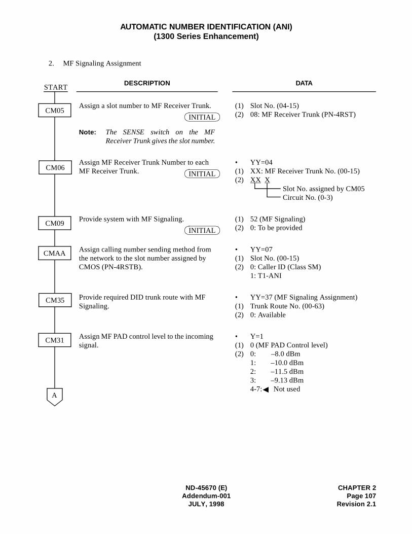
ND-45670 (E) CHAPTER 2Addendum-001 Page 107
JULY, 1998 Revision 2.1
AUTOMATIC NUMBER IDENTIFICATION (ANI)(1300 Series Enhancement)
2. MF Signaling Assignment
DESCRIPTION DATA
Assign a slot number to MF Receiver Trunk.
Note: The SENSE switch on the MFReceiver Trunk gives the slot number.
(1) Slot No. (04-15) (2) 08: MF Receiver Trunk (PN-4RST)
Assign MF Receiver Trunk Number to each MF Receiver Trunk.
• YY=04 (1) XX: MF Receiver Trunk No. (00-15) (2) XX X
Slot No. assigned by CM05Circuit No. (0-3)
Provide system with MF Signaling. (1) 52 (MF Signaling) (2) 0: To be provided
Assign calling number sending method from the network to the slot number assigned by CMOS (PN-4RSTB).
• YY=07(1) Slot No. (00-15)(2) 0: Caller ID (Class SM)
1: T1-ANI
Provide required DID trunk route with MF Signaling.
• YY=37 (MF Signaling Assignment)(1) Trunk Route No. (00-63) (2) 0: Available
Assign MF PAD control level to the incoming signal.
• Y=1 (1) 0 (MF PAD Control level) (2) 0: –8.0 dBm
1: –10.0 dBm 2: –11.5 dBm 3: –9.13 dBm 4-7: Not used
A
CM05
CM06
CM09
CMAA
CM35
START
CM31
INITIAL
INITIAL
INITIAL
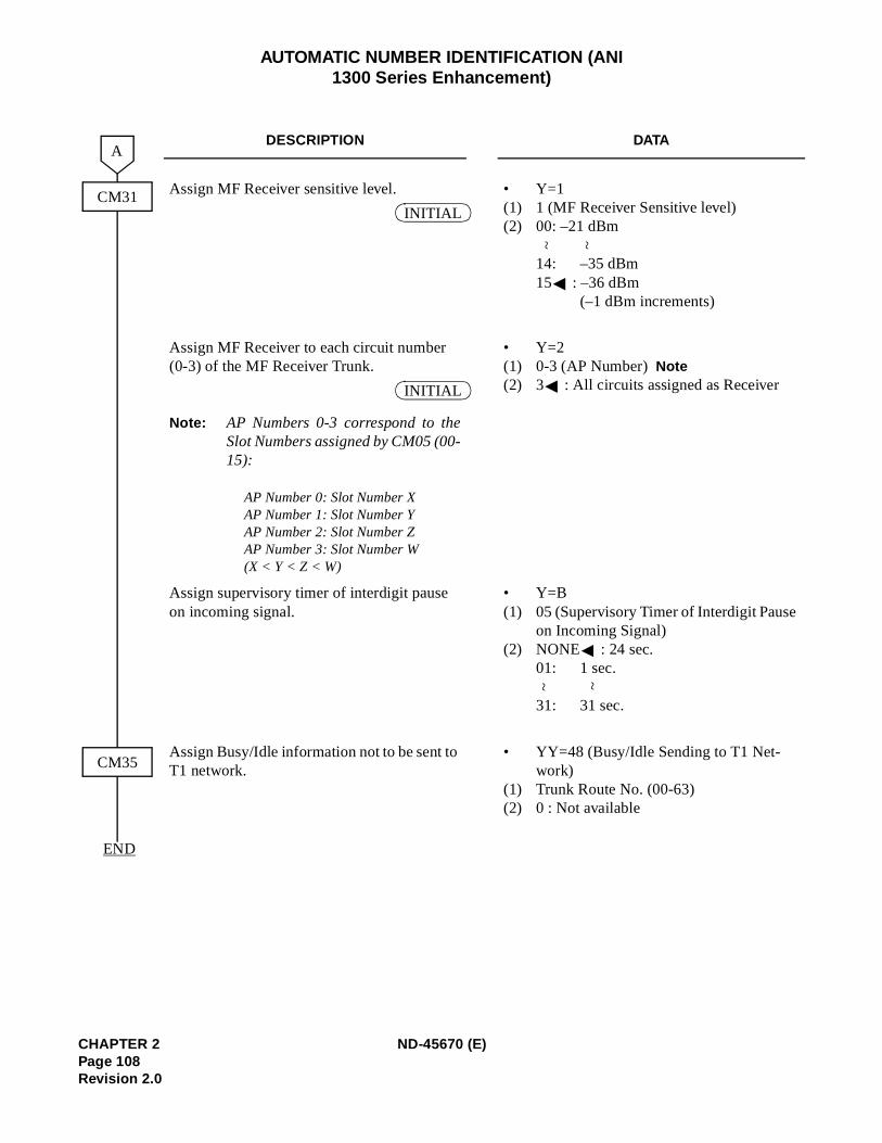
AUTOMATIC NUMBER IDENTIFICATION (ANI 1300 Series Enhancement)
DESCRIPTION DATA
Assign MF Receiver sensitive level. • Y=1 (1) 1 (MF Receiver Sensitive level) (2) 00: –21 dBm
14: –35 dBm 15 : –36 dBm
(–1 dBm increments)
Assign MF Receiver to each circuit number (0-3) of the MF Receiver Trunk.
Note: AP Numbers 0-3 correspond to theSlot Numbers assigned by CM05 (00-15):
AP Number 0: Slot Number X AP Number 1: Slot Number YAP Number 2: Slot Number Z AP Number 3: Slot Number W (X < Y < Z < W)
• Y=2 (1) 0-3 (AP Number)Note (2) 3 : All circuits assigned as Receiver
Assign supervisory timer of interdigit pause on incoming signal.
• Y=B (1) 05 (Supervisory Timer of Interdigit Pause
on Incoming Signal) (2) NONE : 24 sec.
01: 1 sec.
31: 31 sec.
Assign Busy/Idle information not to be sent to T1 network.
• YY=48 (Busy/Idle Sending to T1 Net-work)
(1) Trunk Route No. (00-63) (2) 0 : Not available
A
CM31
CM35
END
INITIAL
~~
INITIAL
~ ~
CHAPTER 2 ND-45670 (E)Page 108Revision 2.0
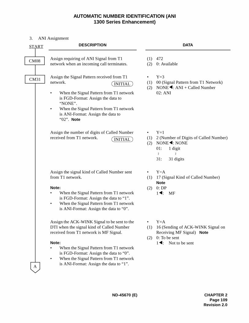
)
AUTOMATIC NUMBER IDENTIFICATION (ANI 1300 Series Enhancement)
3. ANI Assignment
DESCRIPTION DATA
Assign requiring of ANI Signal from T1 network when an incoming call terminates.
(1) 472 (2) 0: Available
Assign the Signal Pattern received from T1 network.
• When the Signal Pattern from T1 network is FGD-Format: Assign the data to “NONE”.
• When the Signal Pattern from T1 network is ANI-Format: Assign the data to “02”. Note
• Y=3 (1) 00 (Signal Pattern from T1 Network) (2) NONE : ANI + Called Number
02: ANI
Assign the number of digits of Called Number received from T1 network.
• Y=1 (1) 2 (Number of Digits of Called Number(2) NONE : NONE
01: 1 digit
31: 31 digits
Assign the signal kind of Called Number sent from T1 network.
Note:• When the Signal Pattern from T1 network
is FGD-Format: Assign the data to “1”. • When the Signal Pattern from T1 network
is ANI-Format: Assign the data to “0”.
• Y=A (1) 17 (Signal Kind of Called Number)
Note(2) 0: DP
1 : MF
Assign the ACK-WINK Signal to be sent to the DTI when the signal kind of Called Number received from T1 network is MF Signal.
Note:• When the Signal Pattern from T1 network
is FGD-Format: Assign the data to “0”. • When the Signal Pattern from T1 network
is ANI-Format: Assign the data to “1”.
• Y=A (1) 16 (Sending of ACK-WINK Signal on
Receiving MF Signal) Note(2) 0: To be sent
1 : Not to be sent
A
CM08
CM31
START
INITIAL
INITIAL
~ ~
ND-45670 (E) CHAPTER 2Page 109
Revision 2.0
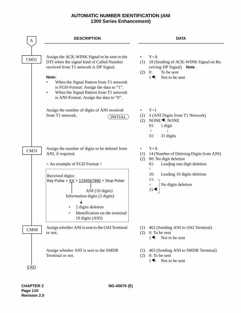
-
AUTOMATIC NUMBER IDENTIFICATION (ANI 1300 Series Enhancement)
DESCRIPTION DATA
Assign the ACK-WINK Signal to be sent to the DTI when the signal kind of Called Number received from T1 network is DP Signal.
Note:• When the Signal Pattern from T1 network
is FGD-Format: Assign the data to “1”. • When the Signal Pattern from T1 network
is ANI-Format: Assign the data to “0”.
• Y=A (1) 18 (Sending of ACK-WINK Signal on Re
ceiving DP Signal) Note(2) 0: To be sent
1 : Not to be sent
Assign the number of digits of ANI received from T1 network.
• Y=1 (1) 3 (ANI Digits from T1 Network) (2) NONE : NONE
01: 1 digit
31: 31 digits
Assign the number of digits to be deleted from ANI, if required.
< An example of FGD Format >
• Y=A (1) 14 (Number of Deleting Digits from ANI)(2) 00: No digit deletion
01: Leading one digit deletion
10: Leading 10 digits deletion 11:
No digits deletion15 :
Assign whether ANI is sent to the OAI Terminal or not.
(1) 462 (Sending ANI to OAI Terminal) (2) 0: To be sent
1 : Not to be sent
Assign whether ANI is sent to the SMDR Terminal or not.
(1) 463 (Sending ANI to SMDR Terminal) (2) 0: To be sent
1 : Not to be sent
A
CM31
CM08
END
CM31
INITIAL
~ ~
Received digits: Key Pulse + XX + 1234567890 + Stop Pulse
ANI (10 digits)Information digits (2 digits)
• 2 digits deletion
• Identification on the terminal: 10 digits (ANI)
~~
~
CHAPTER 2 ND-45670 (E)Page 110Revision 2.0
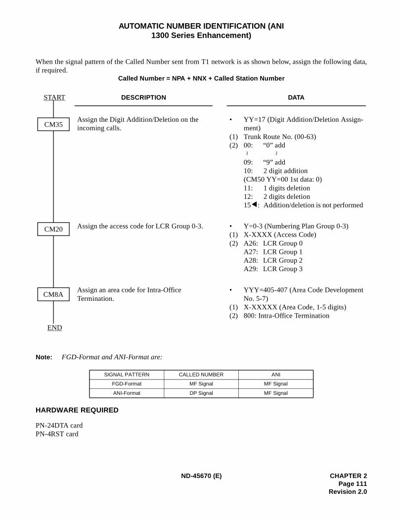
g data,
AUTOMATIC NUMBER IDENTIFICATION (ANI 1300 Series Enhancement)
When the signal pattern of the Called Number sent from T1 network is as shown below, assign the followinif required.
Called Number = NPA + NNX + Called Station Number
Note: FGD-Format and ANI-Format are:
HARDWARE REQUIRED
PN-24DTA cardPN-4RST card
DESCRIPTION DATA
Assign the Digit Addition/Deletion on the incoming calls.
•
(1)(2)
YY=17 (Digit Addition/Deletion Assign-ment) Trunk Route No. (00-63) 00: “0” add
09: “9” add 10: 2 digit addition (CM50 YY=00 1st data: 0) 11: 1 digits deletion 12: 2 digits deletion 15 : Addition/deletion is not performed
Assign the access code for LCR Group 0-3. •(1)(2)
Y=0-3 (Numbering Plan Group 0-3) X-XXXX (Access Code) A26: LCR Group 0 A27: LCR Group 1 A28: LCR Group 2 A29: LCR Group 3
Assign an area code for Intra-Office Termination.
•
(1)(2)
YYY=405-407 (Area Code DevelopmentNo. 5-7) X-XXXXX (Area Code, 1-5 digits) 800: Intra-Office Termination
SIGNAL PATTERN CALLED NUMBER ANI
FGD-Format MF Signal MF Signal
ANI-Format DP Signal MF Signal
CM35
CM20
CM8A
START
END
~ ~
ND-45670 (E) CHAPTER 2Page 111
Revision 2.0
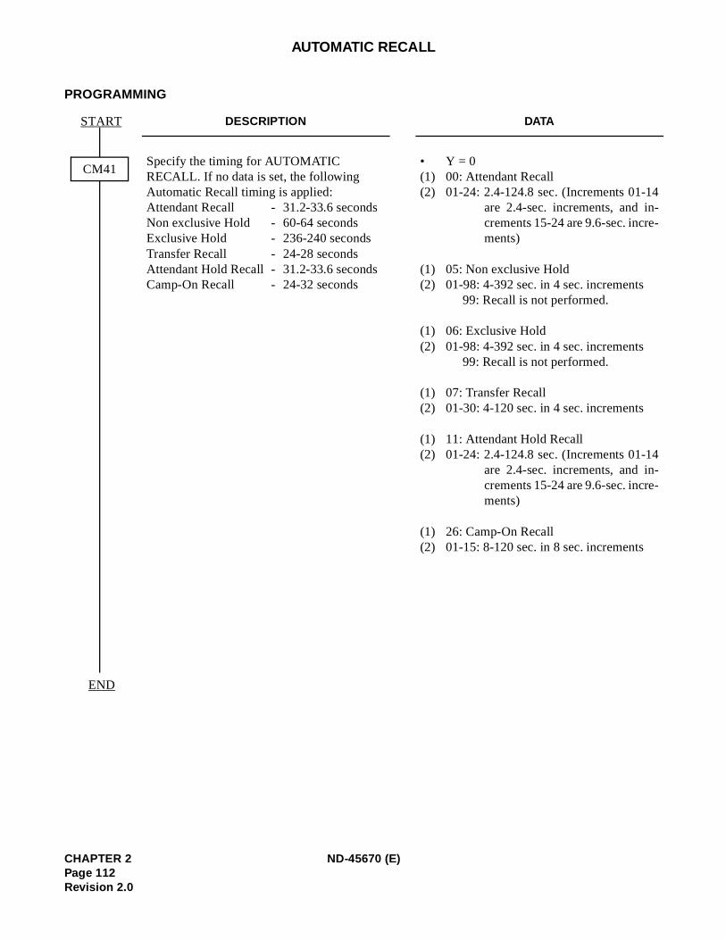
4--
4--
AUTOMATIC RECALL
PROGRAMMING
DESCRIPTION DATA
Specify the timing for AUTOMATIC RECALL. If no data is set, the following Automatic Recall timing is applied:Attendant Recall - 31.2-33.6 secondsNon exclusive Hold - 60-64 secondsExclusive Hold - 236-240 secondsTransfer Recall - 24-28 secondsAttendant Hold Recall - 31.2-33.6 secondsCamp-On Recall - 24-32 seconds
• Y = 0(1) 00: Attendant Recall(2) 01-24: 2.4-124.8 sec. (Increments 01-1
are 2.4-sec. increments, and increments 15-24 are 9.6-sec. increments)
(1) 05: Non exclusive Hold(2) 01-98: 4-392 sec. in 4 sec. increments
99: Recall is not performed.
(1) 06: Exclusive Hold(2) 01-98: 4-392 sec. in 4 sec. increments
99: Recall is not performed.
(1) 07: Transfer Recall(2) 01-30: 4-120 sec. in 4 sec. increments
(1) 11: Attendant Hold Recall(2) 01-24: 2.4-124.8 sec. (Increments 01-1
are 2.4-sec. increments, and increments 15-24 are 9.6-sec. increments)
(1) 26: Camp-On Recall(2) 01-15: 8-120 sec. in 8 sec. increments
CM41
START
END
CHAPTER 2 ND-45670 (E)Page 112Revision 2.0
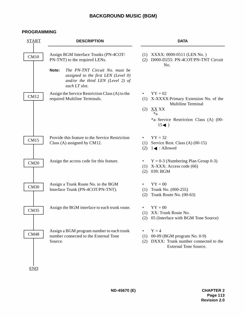
)
BACKGROUND MUSIC (BGM)
PROGRAMMING
DESCRIPTION DATA
Assign BGM Interface Trunks (PN-4COT/PN-TNT) to the required LENs.
Note: The PN-TNT Circuit No. must beassigned to the first LEN (Level 0)and/or the third LEN (Level 2) ofeach LT slot.
(1) XXXX: 0000-0511 (LEN No. )(2) D000-D255: PN-4COT/PN-TNT Circuit
No.
Assign the Service Restriction Class (A) to the required Multiline Terminals.
• YY = 02(1) X-XXXX:Primary Extension No. of the
Multiline Terminal(2) XX XX
*a: Service Restriction Class (A) (00-15 )
Provide this feature to the Service Restriction Class (A) assigned by CM12.
• YY = 32(1) Service Rest. Class (A) (00-15)(2) 1 : Allowed
Assign the access code for this feature. • Y = 0-3 (Numbering Plan Group 0-3(1) X-XXX: Access code (66)(2) 039: BGM
Assign a Trunk Route No. to the BGM Interface Trunk (PN-4COT/PN-TNT).
• YY = 00(1) Trunk No. (000-255)(2) Trunk Route No. (00-63)
Assign the BGM interface to each trunk route. • YY = 00(1) XX: Trunk Route No. (2) 05 (Interface with BGM Tone Source)
Assign a BGM program number to each trunk number connected to the External Tone Source.
• Y = 4(1) 00-09 (BGM program No. 0-9)(2) DXXX: Trunk number connected to the
External Tone Source.
CM10
START
CM12
CM35
CM15
CM20
CM30
CM48
END
*a
ND-45670 (E) CHAPTER 2Page 113
Revision 2.0
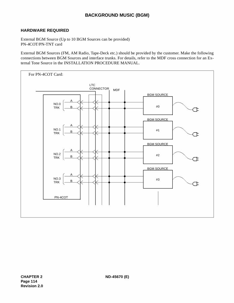
lowingEx-
BACKGROUND MUSIC (BGM)
HARDWARE REQUIRED
External BGM Source (Up to 10 BGM Sources can be provided)PN-4COT/PN-TNT card
External BGM Sources (FM, AM Radio, Tape-Deck etc.) should be provided by the customer. Make the folconnections between BGM Sources and interface trunks. For details, refer to the MDF cross connection for an ternal Tone Source in the INSTALLATION PROCEDURE MANUAL.
For PN-4COT Card:
LTC CONNECTOR MDF
NO.0 TRK
NO.1 TRK
NO.2 TRK
NO.3 TRK
PN-4COT
BGM SOURCE
BGM SOURCE
BGM SOURCE
BGM SOURCE
#0
#1
#2
#3
A
B
A
B
A
B
A
B
CHAPTER 2 ND-45670 (E)Page 114Revision 2.0
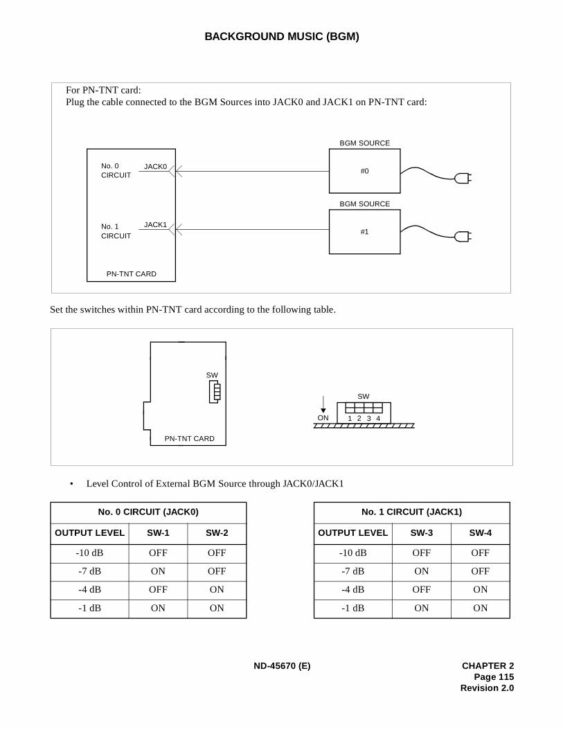
BACKGROUND MUSIC (BGM)
Set the switches within PN-TNT card according to the following table.
• Level Control of External BGM Source through JACK0/JACK1
No. 0 CIRCUIT (JACK0) No. 1 CIRCUIT (JACK1)
OUTPUT LEVEL SW-1 SW-2 OUTPUT LEVEL SW-3 SW-4
-10 dB OFF OFF -10 dB OFF OFF
-7 dB ON OFF -7 dB ON OFF
-4 dB OFF ON -4 dB OFF ON
-1 dB ON ON -1 dB ON ON
For PN-TNT card:Plug the cable connected to the BGM Sources into JACK0 and JACK1 on PN-TNT card:
BGM SOURCE
JACK0#0
JACK1No. 1 #1
PN-TNT CARD
CIRCUIT
No. 0 CIRCUIT
BGM SOURCE
SW
SW
ON 1 2 3 4
PN-TNT CARD
ND-45670 (E) CHAPTER 2Page 115
Revision 2.0
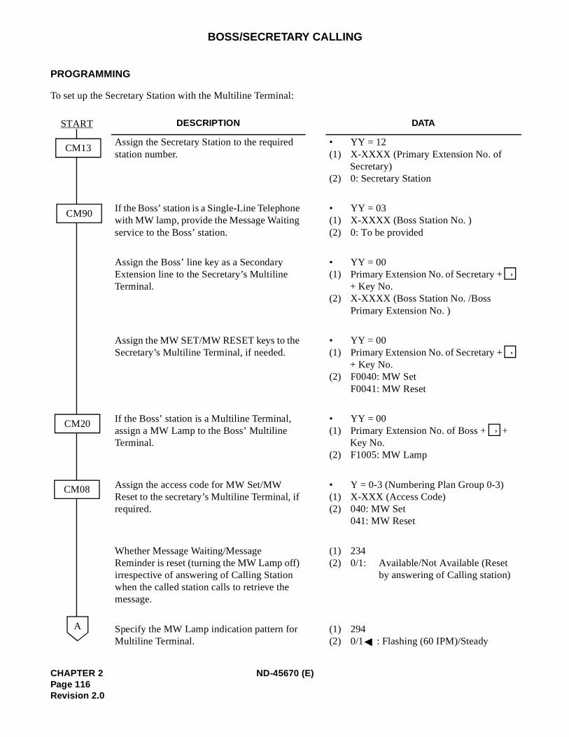
BOSS/SECRETARY CALLING
PROGRAMMING
To set up the Secretary Station with the Multiline Terminal:
DESCRIPTION DATA
Assign the Secretary Station to the required station number.
• YY = 12(1) X-XXXX (Primary Extension No. of
Secretary)(2) 0: Secretary Station
If the Boss’ station is a Single-Line Telephone with MW lamp, provide the Message Waiting service to the Boss’ station.
• YY = 03(1) X-XXXX (Boss Station No. )(2) 0: To be provided
Assign the Boss’ line key as a Secondary Extension line to the Secretary’s Multiline Terminal.
• YY = 00(1) Primary Extension No. of Secretary +
+ Key No. (2) X-XXXX (Boss Station No. /Boss
Primary Extension No. )
Assign the MW SET/MW RESET keys to the Secretary’s Multiline Terminal, if needed.
• YY = 00(1) Primary Extension No. of Secretary +
+ Key No. (2) F0040: MW Set
F0041: MW Reset
If the Boss’ station is a Multiline Terminal, assign a MW Lamp to the Boss’ Multiline Terminal.
• YY = 00(1) Primary Extension No. of Boss + +
Key No. (2) F1005: MW Lamp
Assign the access code for MW Set/MW Reset to the secretary’s Multiline Terminal, if required.
• Y = 0-3 (Numbering Plan Group 0-3)(1) X-XXX (Access Code)(2) 040: MW Set
041: MW Reset
Whether Message Waiting/Message Reminder is reset (turning the MW Lamp off) irrespective of answering of Calling Station when the called station calls to retrieve the message.
(1) 234(2) 0/1: Available/Not Available (Reset
by answering of Calling station)
Specify the MW Lamp indication pattern for Multiline Terminal.
(1) 294(2) 0/1 : Flashing (60 IPM)/Steady
CM13
START
CM90
CM20
CM08
A
,
,
,
CHAPTER 2 ND-45670 (E)Page 116Revision 2.0
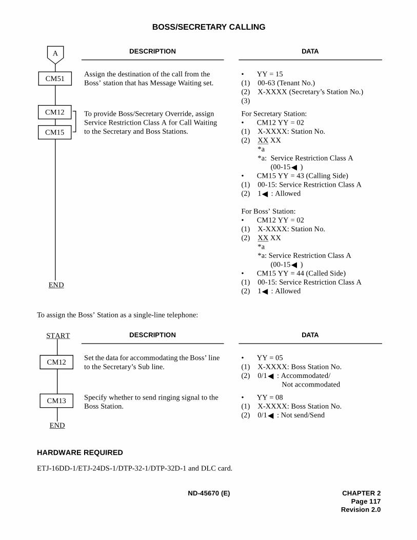
BOSS/SECRETARY CALLING
To assign the Boss’ Station as a single-line telephone:
HARDWARE REQUIRED
ETJ-16DD-1/ETJ-24DS-1/DTP-32-1/DTP-32D-1 and DLC card.
DESCRIPTION DATA
Assign the destination of the call from the Boss’ station that has Message Waiting set.
• YY = 15(1) 00-63 (Tenant No.)(2) X-XXXX (Secretary’s Station No.)(3)
To provide Boss/Secretary Override, assign Service Restriction Class A for Call Waiting to the Secretary and Boss Stations.
For Secretary Station:• CM12 YY = 02(1) X-XXXX: Station No. (2) XX XX
*a*a: Service Restriction Class A
(00-15 )• CM15 YY = 43 (Calling Side)(1) 00-15: Service Restriction Class A (2) 1 : Allowed
For Boss’ Station:• CM12 YY = 02(1) X-XXXX: Station No. (2) XX XX
*a*a: Service Restriction Class A
(00-15 )• CM15 YY = 44 (Called Side)(1) 00-15: Service Restriction Class A(2) 1 : Allowed
DESCRIPTION DATA
Set the data for accommodating the Boss’ line to the Secretary’s Sub line.
• YY = 05(1) X-XXXX: Boss Station No. (2) 0/1 : Accommodated/
Not accommodated
Specify whether to send ringing signal to the Boss Station.
• YY = 08(1) X-XXXX: Boss Station No. (2) 0/1 : Not send/Send
CM51
END
A
CM12
CM15
CM12
START
CM13
END
ND-45670 (E) CHAPTER 2Page 117
Revision 2.0

BROKER’S CALL
PROGRAMMING
Refer to CALL HOLD feature.
CHAPTER 2 ND-45670 (E)Page 118Revision 2.0
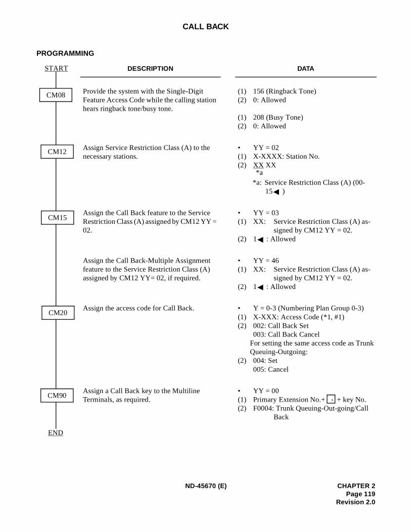
)
nk
CALL BACK
PROGRAMMING
DESCRIPTION DATA
Provide the system with the Single-Digit Feature Access Code while the calling station hears ringback tone/busy tone.
(1) 156 (Ringback Tone)(2) 0: Allowed (1) 208 (Busy Tone)(2) 0: Allowed
Assign Service Restriction Class (A) to the necessary stations.
• YY = 02(1) X-XXXX: Station No. (2) XX XX
*a: Service Restriction Class (A) (00-15 )
Assign the Call Back feature to the Service Restriction Class (A) assigned by CM12 YY = 02.
• YY = 03(1) XX: Service Restriction Class (A) as-
signed by CM12 YY = 02.(2) 1 : Allowed
Assign the Call Back-Multiple Assignment feature to the Service Restriction Class (A) assigned by CM12 YY= 02, if required.
• YY = 46(1) XX: Service Restriction Class (A) as-
signed by CM12 YY = 02.(2) 1 : Allowed
Assign the access code for Call Back. • Y = 0-3 (Numbering Plan Group 0-3(1) X-XXX: Access Code (*1, #1)(2) 002: Call Back Set
003: Call Back CancelFor setting the same access code as TruQueuing-Outgoing:
(2) 004: Set005: Cancel
Assign a Call Back key to the Multiline Terminals, as required.
• YY = 00(1) Primary Extension No.+ + key No. (2) F0004: Trunk Queuing-Out-going/Call
Back
CM08
START
CM12
CM15
CM20
CM90
END
*a
,
ND-45670 (E) CHAPTER 2Page 119
Revision 2.0
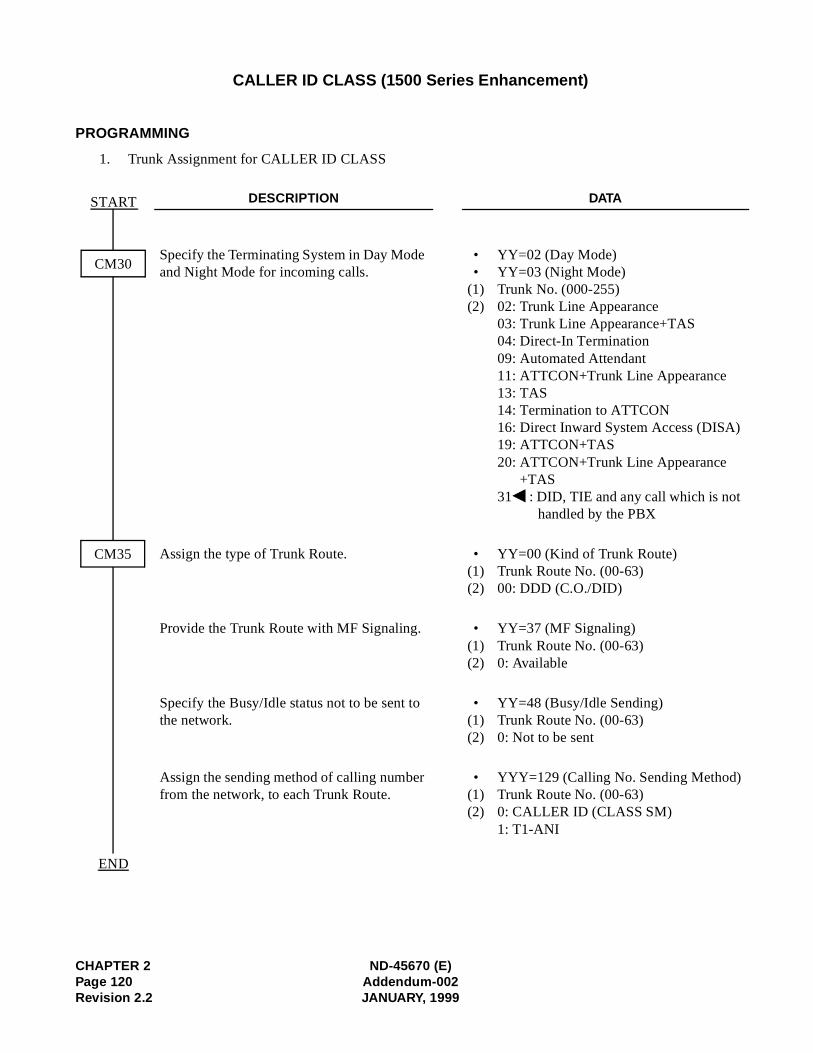
CHAPTER 2 ND-45670 (E)Page 120 Addendum-002Revision 2.2 JANUARY, 1999
CALLER ID CLASS (1500 Series Enhancement)
PROGRAMMING
1. Trunk Assignment for CALLER ID CLASS
DESCRIPTION DATA
Specify the Terminating System in Day Mode and Night Mode for incoming calls.
• YY=02 (Day Mode) • YY=03 (Night Mode)
(1) Trunk No. (000-255) (2) 02: Trunk Line Appearance
03: Trunk Line Appearance+TAS04: Direct-In Termination09: Automated Attendant11: ATTCON+Trunk Line Appearance13: TAS14: Termination to ATTCON16: Direct Inward System Access (DISA)19: ATTCON+TAS20: ATTCON+Trunk Line Appearance
+TAS31 : DID, TIE and any call which is not
handled by the PBX
Assign the type of Trunk Route. • YY=00 (Kind of Trunk Route) (1) Trunk Route No. (00-63) (2) 00: DDD (C.O./DID)
Provide the Trunk Route with MF Signaling. • YY=37 (MF Signaling) (1) Trunk Route No. (00-63) (2) 0: Available
Specify the Busy/Idle status not to be sent to the network.
• YY=48 (Busy/Idle Sending) (1) Trunk Route No. (00-63) (2) 0: Not to be sent
Assign the sending method of calling number from the network, to each Trunk Route.
• YYY=129 (Calling No. Sending Method)(1) Trunk Route No. (00-63) (2) 0: CALLER ID (CLASS SM)
1: T1-ANI
CM35
CM30
START
END
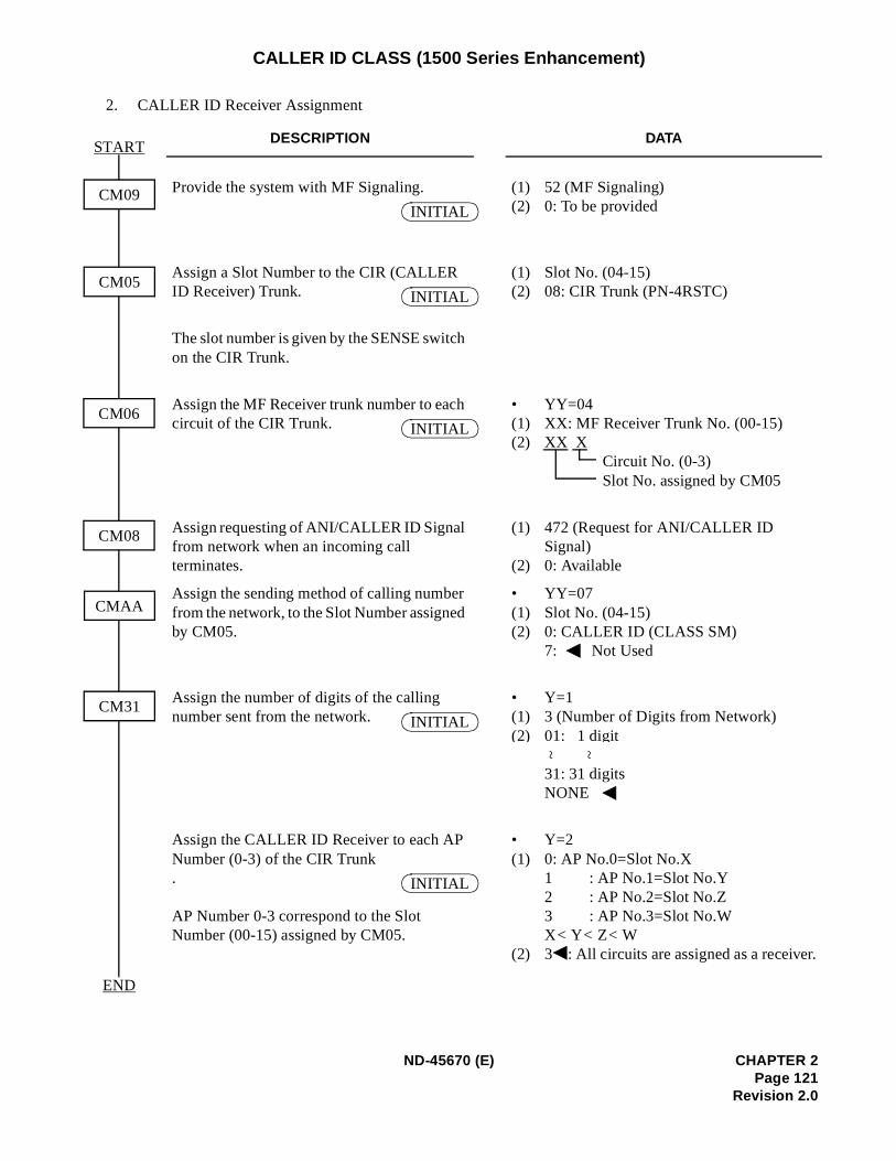
r.
CALLER ID CLASS (1500 Series Enhancement)
2. CALLER ID Receiver Assignment
DESCRIPTION DATA
Provide the system with MF Signaling. (1) 52 (MF Signaling)(2) 0: To be provided
Assign a Slot Number to the CIR (CALLER ID Receiver) Trunk.
(1) Slot No. (04-15) (2) 08: CIR Trunk (PN-4RSTC)
The slot number is given by the SENSE switch on the CIR Trunk.
Assign the MF Receiver trunk number to each circuit of the CIR Trunk.
• YY=04 (1) XX: MF Receiver Trunk No. (00-15) (2) XX X
Circuit No. (0-3) Slot No. assigned by CM05
Assign requesting of ANI/CALLER ID Signal from network when an incoming call terminates.
(1) 472 (Request for ANI/CALLER ID Signal)
(2) 0: Available
Assign the sending method of calling number from the network, to the Slot Number assigned by CM05.
• YY=07 (1) Slot No. (04-15) (2) 0: CALLER ID (CLASS SM)
7: Not Used
Assign the number of digits of the calling number sent from the network.
• Y=1 (1) 3 (Number of Digits from Network) (2) 01: 1 digit
31: 31 digits NONE
Assign the CALLER ID Receiver to each AP Number (0-3) of the CIR Trunk.
AP Number 0-3 correspond to the Slot Number (00-15) assigned by CM05.
• Y=2 (1) 0: AP No.0=Slot No.X
1 : AP No.1=Slot No.Y 2 : AP No.2=Slot No.Z3 : AP No.3=Slot No.WX< Y< Z< W
(2) 3 : All circuits are assigned as a receive
CM05
CM06
CM31
CMAA
START
END
CM09
CM08
INITIAL
INITIAL
INITIAL
INITIAL
~ ~
INITIAL
ND-45670 (E) CHAPTER 2Page 121
Revision 2.0
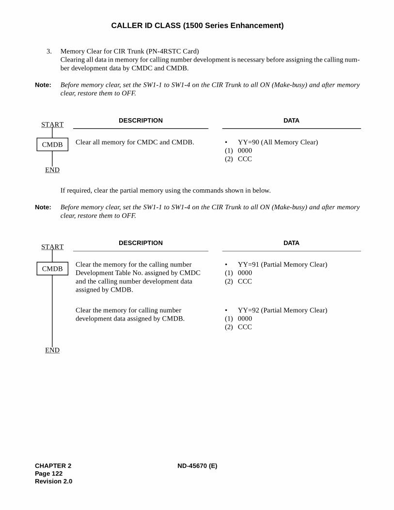
g num-
emory
emory
CALLER ID CLASS (1500 Series Enhancement)
3. Memory Clear for CIR Trunk (PN-4RSTC Card)Clearing all data in memory for calling number development is necessary before assigning the callinber development data by CMDC and CMDB.
Note: Before memory clear, set the SW1-1 to SW1-4 on the CIR Trunk to all ON (Make-busy) and after mclear, restore them to OFF.
If required, clear the partial memory using the commands shown in below.
Note: Before memory clear, set the SW1-1 to SW1-4 on the CIR Trunk to all ON (Make-busy) and after mclear, restore them to OFF.
DESCRIPTION DATA
Clear all memory for CMDC and CMDB. •(1)(2)
YY=90 (All Memory Clear)0000CCC
DESCRIPTION DATA
Clear the memory for the calling number Development Table No. assigned by CMDC and the calling number development data assigned by CMDB.
•(1)(2)
YY=91 (Partial Memory Clear)0000CCC
Clear the memory for calling number development data assigned by CMDB.
•(1)(2)
YY=92 (Partial Memory Clear)0000CCC
START
END
CMDB
START
END
CMDB
CHAPTER 2 ND-45670 (E)Page 122Revision 2.0
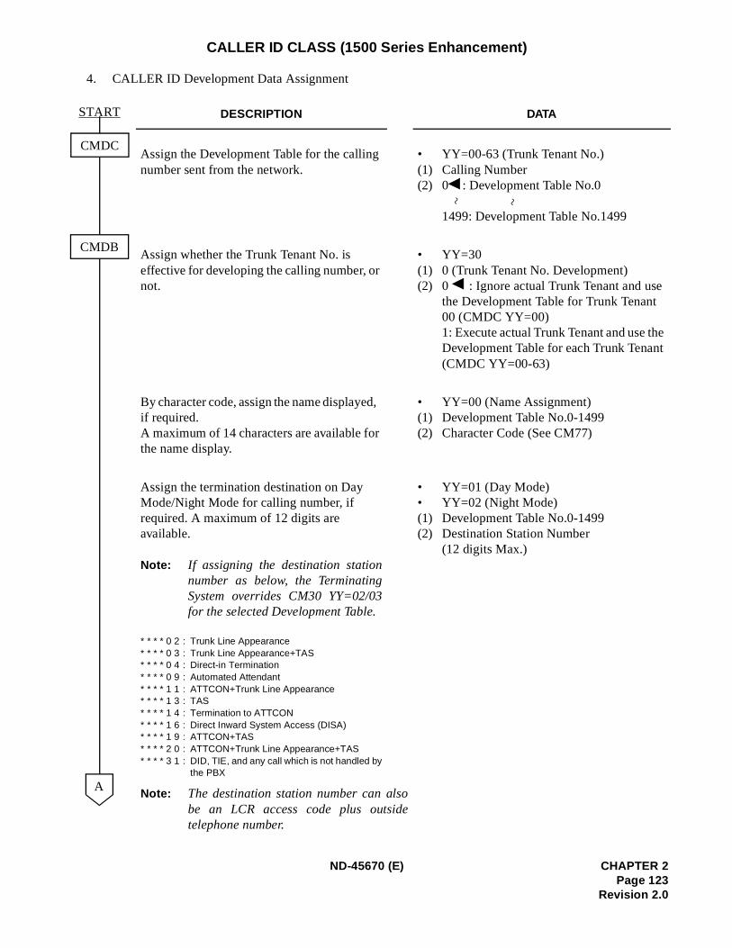
e t
CALLER ID CLASS (1500 Series Enhancement)
4. CALLER ID Development Data Assignment
DESCRIPTION DATA
Assign the Development Table for the calling number sent from the network.
•(1)(2)
YY=00-63 (Trunk Tenant No.) Calling Number0 : Development Table No.0
1499: Development Table No.1499
Assign whether the Trunk Tenant No. is effective for developing the calling number, or not.
•(1)(2)
YY=30 0 (Trunk Tenant No. Development) 0 : Ignore actual Trunk Tenant and usethe Development Table for Trunk Tenant 00 (CMDC YY=00)1: Execute actual Trunk Tenant and use thDevelopment Table for each Trunk Tenan(CMDC YY=00-63)
By character code, assign the name displayed, if required.A maximum of 14 characters are available for the name display.
•(1)(2)
YY=00 (Name Assignment)Development Table No.0-1499Character Code (See CM77)
Assign the termination destination on Day Mode/Night Mode for calling number, if required. A maximum of 12 digits are available.
Note: If assigning the destination stationnumber as below, the TerminatingSystem overrides CM30 YY=02/03for the selected Development Table.
* * * * 0 2 : Trunk Line Appearance* * * * 0 3 : Trunk Line Appearance+TAS* * * * 0 4 : Direct-in Termination * * * * 0 9 : Automated Attendant* * * * 1 1 : ATTCON+Trunk Line Appearance* * * * 1 3 : TAS* * * * 1 4 : Termination to ATTCON* * * * 1 6 : Direct Inward System Access (DISA)* * * * 1 9 : ATTCON+TAS* * * * 2 0 : ATTCON+Trunk Line Appearance+TAS* * * * 3 1 : DID, TIE, and any call which is not handled by
the PBX
••(1)(2)
YY=01 (Day Mode)YY=02 (Night Mode)Development Table No.0-1499Destination Station Number(12 digits Max.)
Note: The destination station number can alsobe an LCR access code plus outsidetelephone number.
CMDC
START
CMDB
A
~ ~
ND-45670 (E) CHAPTER 2Page 123
Revision 2.0
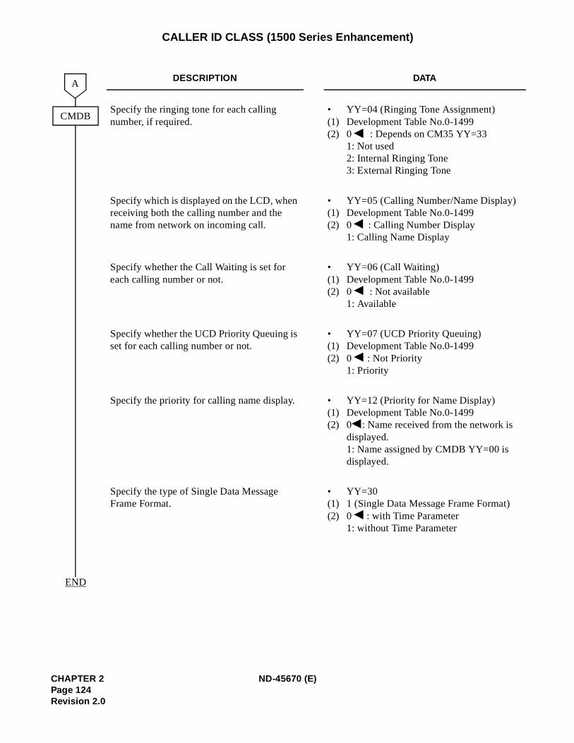
CALLER ID CLASS (1500 Series Enhancement)
DESCRIPTION DATA
Specify the ringing tone for each calling number, if required.
•(1)(2)
YY=04 (Ringing Tone Assignment)Development Table No.0-14990 : Depends on CM35 YY=331: Not used2: Internal Ringing Tone3: External Ringing Tone
Specify which is displayed on the LCD, when receiving both the calling number and the name from network on incoming call.
•(1)(2)
YY=05 (Calling Number/Name Display) Development Table No.0-14990 : Calling Number Display 1: Calling Name Display
Specify whether the Call Waiting is set for each calling number or not.
•(1)(2)
YY=06 (Call Waiting) Development Table No.0-14990 : Not available1: Available
Specify whether the UCD Priority Queuing is set for each calling number or not.
•(1)(2)
YY=07 (UCD Priority Queuing)Development Table No.0-14990 : Not Priority1: Priority
Specify the priority for calling name display. •(1)(2)
YY=12 (Priority for Name Display) Development Table No.0-14990 : Name received from the network is displayed.1: Name assigned by CMDB YY=00 is displayed.
Specify the type of Single Data Message Frame Format.
•(1)(2)
YY=301 (Single Data Message Frame Format)0 : with Time Parameter1: without Time Parameter
CMDB
END
A
CHAPTER 2 ND-45670 (E)Page 124Revision 2.0
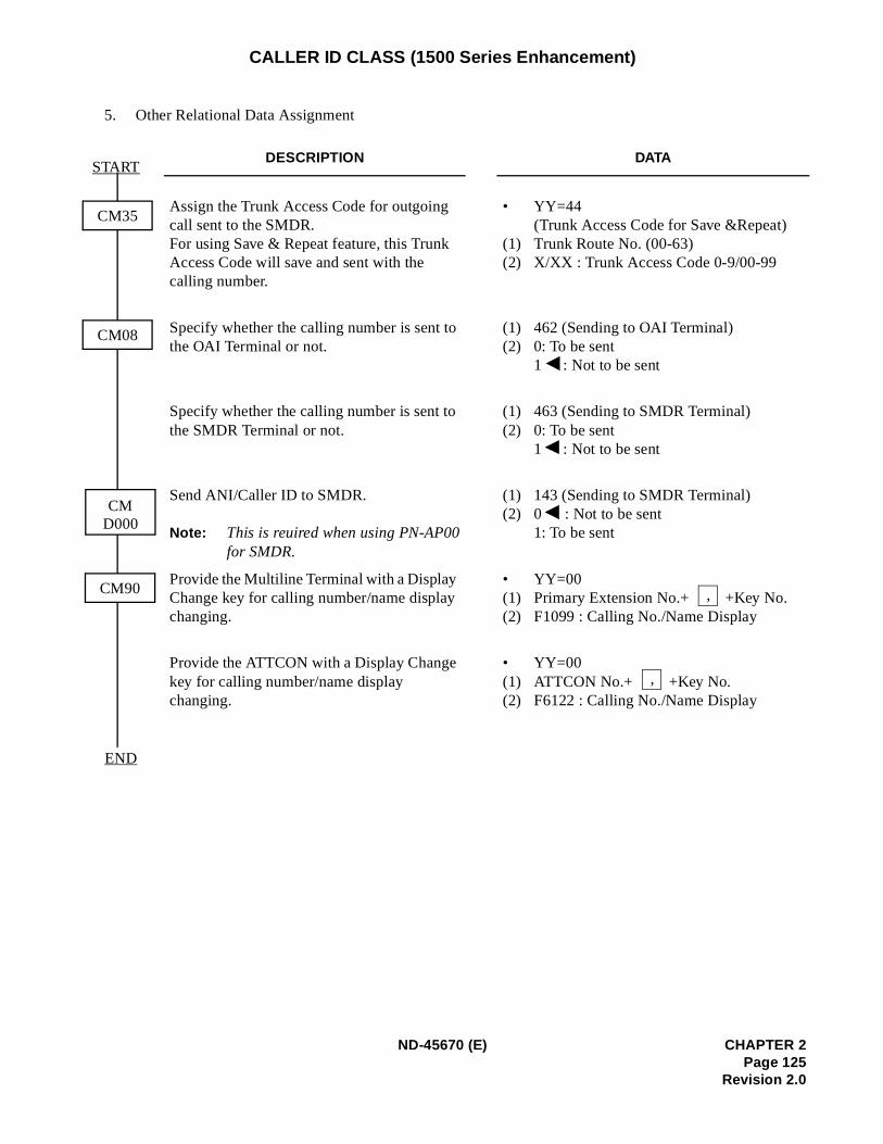
CALLER ID CLASS (1500 Series Enhancement)
5. Other Relational Data Assignment
DESCRIPTION DATA
Assign the Trunk Access Code for outgoing call sent to the SMDR.For using Save & Repeat feature, this Trunk Access Code will save and sent with the calling number.
•
(1)(2)
YY=44(Trunk Access Code for Save &Repeat) Trunk Route No. (00-63) X/XX : Trunk Access Code 0-9/00-99
Specify whether the calling number is sent to the OAI Terminal or not.
(1)(2)
462 (Sending to OAI Terminal) 0: To be sent 1 : Not to be sent
Specify whether the calling number is sent to the SMDR Terminal or not.
(1)(2)
463 (Sending to SMDR Terminal) 0: To be sent 1 : Not to be sent
Send ANI/Caller ID to SMDR.
Note: This is reuired when using PN-AP00for SMDR.
(1)(2)
143 (Sending to SMDR Terminal)0 : Not to be sent 1: To be sent
Provide the Multiline Terminal with a Display Change key for calling number/name display changing.
•(1)(2)
YY=00Primary Extension No.+ +Key No.F1099 : Calling No./Name Display
Provide the ATTCON with a Display Change key for calling number/name display changing.
•(1)(2)
YY=00ATTCON No.+ +Key No.F6122 : Calling No./Name Display
CM35
CM08
CM90
START
END
CMD000
,
,
ND-45670 (E) CHAPTER 2Page 125
Revision 2.0
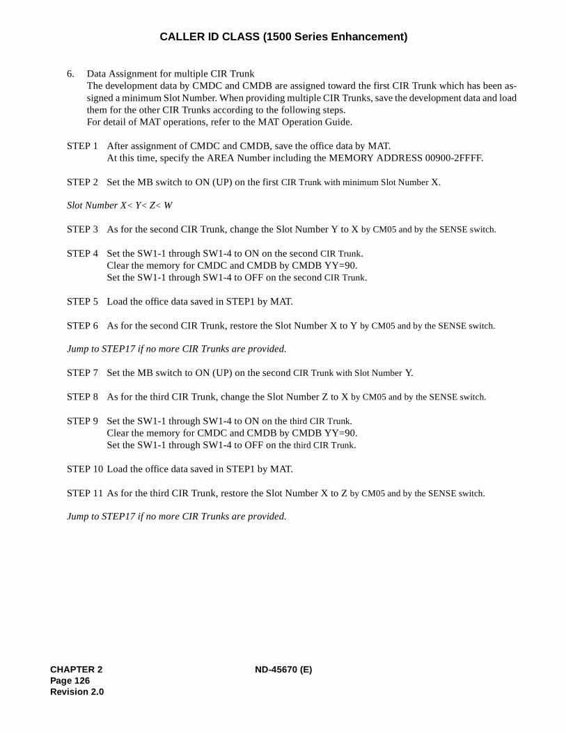
en as-d load
CALLER ID CLASS (1500 Series Enhancement)
6. Data Assignment for multiple CIR TrunkThe development data by CMDC and CMDB are assigned toward the first CIR Trunk which has besigned a minimum Slot Number. When providing multiple CIR Trunks, save the development data anthem for the other CIR Trunks according to the following steps.For detail of MAT operations, refer to the MAT Operation Guide.
STEP 1 After assignment of CMDC and CMDB, save the office data by MAT.At this time, specify the AREA Number including the MEMORY ADDRESS 00900-2FFFF.
STEP 2 Set the MB switch to ON (UP) on the first CIR Trunk with minimum Slot Number X.
Slot Number X< Y< Z< W
STEP 3 As for the second CIR Trunk, change the Slot Number Y to X by CM05 and by the SENSE switch.
STEP 4 Set the SW1-1 through SW1-4 to ON on the second CIR Trunk.Clear the memory for CMDC and CMDB by CMDB YY=90.Set the SW1-1 through SW1-4 to OFF on the second CIR Trunk.
STEP 5 Load the office data saved in STEP1 by MAT.
STEP 6 As for the second CIR Trunk, restore the Slot Number X to Y by CM05 and by the SENSE switch.
Jump to STEP17 if no more CIR Trunks are provided.
STEP 7 Set the MB switch to ON (UP) on the second CIR Trunk with Slot Number Y.
STEP 8 As for the third CIR Trunk, change the Slot Number Z to X by CM05 and by the SENSE switch.
STEP 9 Set the SW1-1 through SW1-4 to ON on the third CIR Trunk.Clear the memory for CMDC and CMDB by CMDB YY=90.Set the SW1-1 through SW1-4 to OFF on the third CIR Trunk.
STEP 10 Load the office data saved in STEP1 by MAT.
STEP 11 As for the third CIR Trunk, restore the Slot Number X to Z by CM05 and by the SENSE switch.
Jump to STEP17 if no more CIR Trunks are provided.
CHAPTER 2 ND-45670 (E)Page 126Revision 2.0
CALLER ID CLASS (1500 Series Enhancement)
STEP 12 Set the MB switch to ON (UP) on the third CIR Trunk with Slot Number Z.
STEP 13 As for the fourth CIR Trunk, change the Slot Number W to X by CM05 and by the SENSE switch.
STEP 14 Set the SW1-1 through SW1-4 to ON on the fourth CIR Trunk.Clear the memory for CMDC and CMDB by CMDB YY=90.Set the SW1-1 through SW1-4 to OFF on the fourth CIR Trunk.
STEP 15 Load the office data saved in STEP1 by MAT.
STEP 16 As for the fourth CIR Trunk, restore the Slot Number X to W by CM05 and by the SENSE switch.
STEP 17 Set the MB switches to OFF (DOWN) on all the CIR Trunks.
HARDWARE REQUIRED
PN-4COTG cardPN-4RSTC card
ND-45670 (E) CHAPTER 2Page 127
Revision 2.0
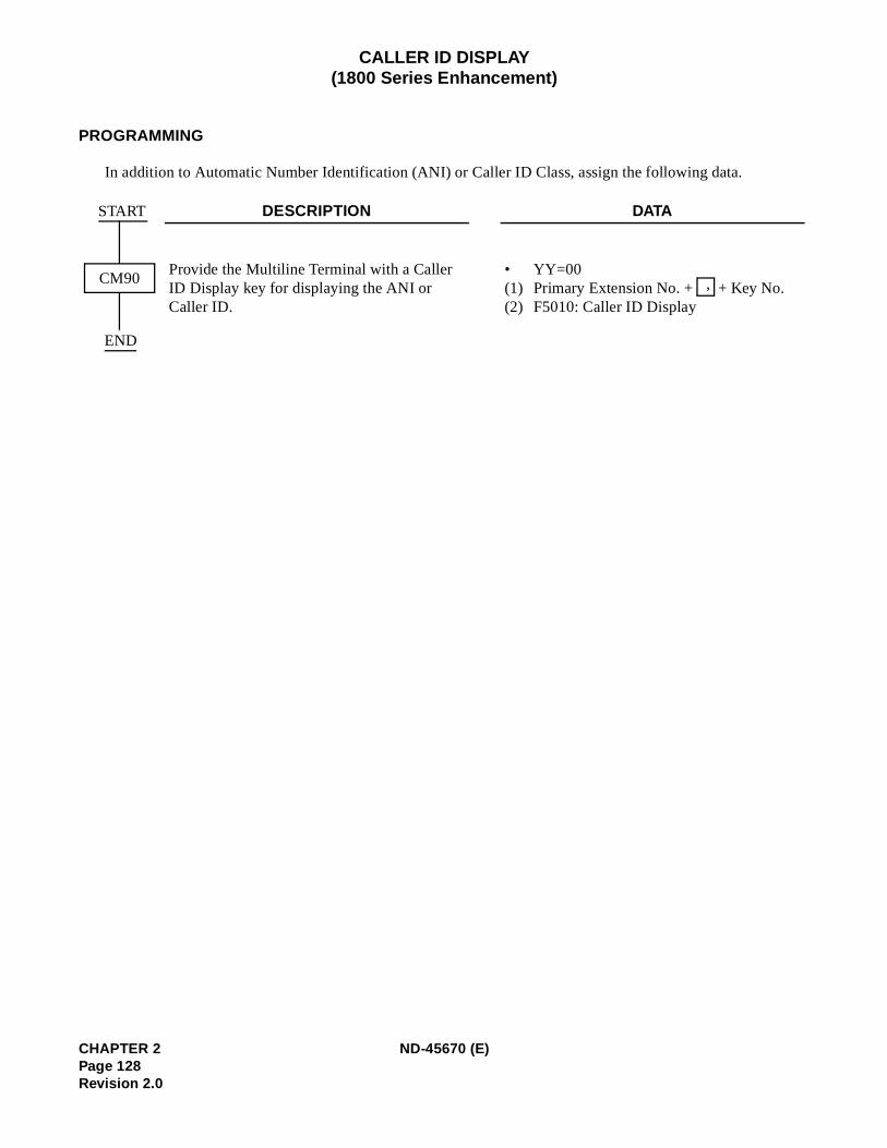
CALLER ID DISPLAY(1800 Series Enhancement)
PROGRAMMING
In addition to Automatic Number Identification (ANI) or Caller ID Class, assign the following data.
DESCRIPTION DATA
Provide the Multiline Terminal with a Caller ID Display key for displaying the ANI or Caller ID.
•(1)(2)
YY=00Primary Extension No. + + Key No.F5010: Caller ID Display
START
END
CM90 ,
CHAPTER 2 ND-45670 (E)Page 128Revision 2.0
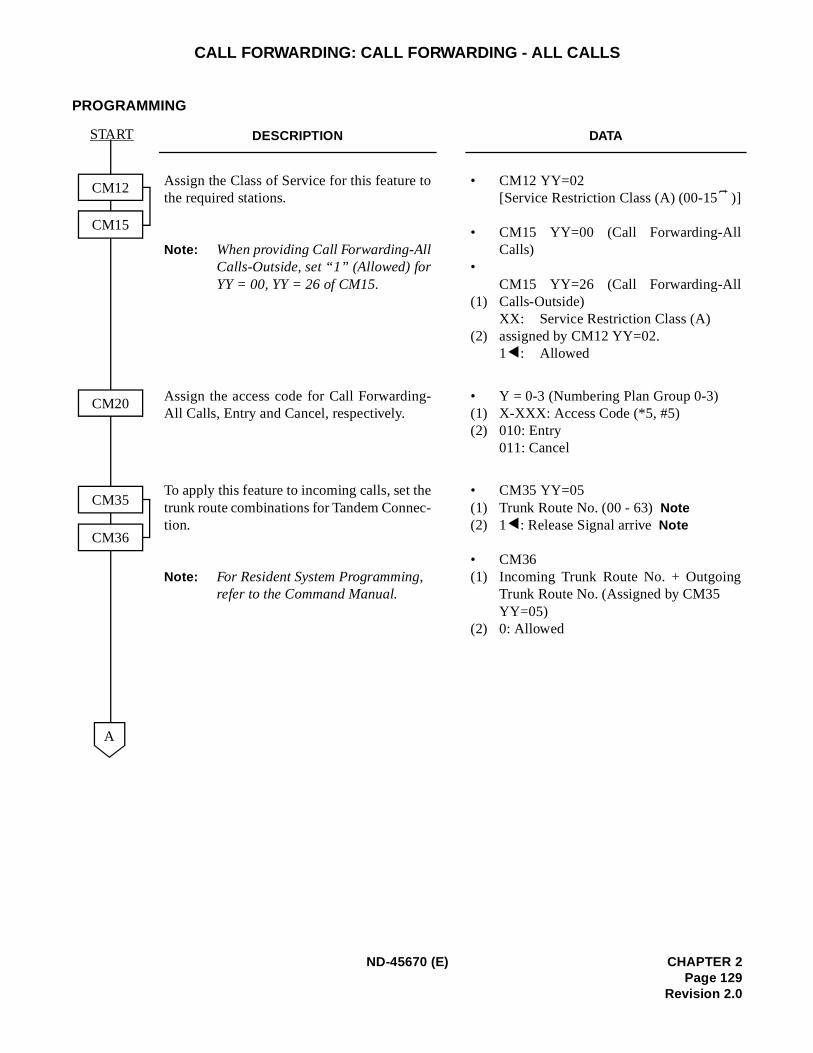
CALL FORWARDING: CALL FORWARDING - ALL CALLS
PROGRAMMING
DESCRIPTION DATA
Assign the Class of Service for this feature tothe required stations.
Note: When providing Call Forwarding-AllCalls-Outside, set “1” (Allowed) forYY = 00, YY = 26 of CM15.
•
•
•
(1)
(2)
CM12 YY=02[Service Restriction Class (A) (00-15 )]
CM15 YY=00 (Call Forwarding-AllCalls)
CM15 YY=26 (Call Forwarding-AllCalls-Outside)XX: Service Restriction Class (A) assigned by CM12 YY=02.1 : Allowed
Assign the access code for Call Forwarding-All Calls, Entry and Cancel, respectively.
•(1)(2)
Y = 0-3 (Numbering Plan Group 0-3)X-XXX: Access Code (*5, #5)010: Entry011: Cancel
To apply this feature to incoming calls, set thetrunk route combinations for Tandem Connec-tion.
Note: For Resident System Programming, refer to the Command Manual.
•(1)(2)
•(1)
(2)
CM35 YY=05Trunk Route No. (00 - 63)Note1 : Release Signal arriveNote
CM36Incoming Trunk Route No. + OutgoingTrunk Route No. (Assigned by CM35 YY=05)0: Allowed
CM12
CM15
CM20
CM35
CM36
A
START
t
ND-45670 (E) CHAPTER 2Page 129
Revision 2.0
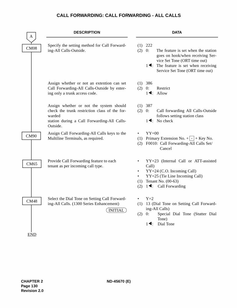
n-
g
-
CALL FORWARDING: CALL FORWARDING - ALL CALLS
DESCRIPTION DATA
Specify the setting method for Call Forward-ing-All Calls-Outside.
(1)(2)
2220: The feature is set when the statio
goes on hook/when receiving Service Set Tone (ORT time out)
1 : The feature is set when receivinService Set Tone (ORT time out)
Assign whether or not an extention can setCall Forwarding-All Calls-Outside by enter-ing only a trunk access code.
(1)(2)
3860: Restrict1 : Allow
Assign whether or not the system shouldcheck the trunk restriction class of the for-warded station during a Call Forwarding-All Calls-Outside.
(1)(2)
3870: Call forwarding All Calls-Outside
follows setting station class1 : No check
Assign Call Forwarding-All Calls keys to theMultiline Terminals, as required.
•(1)(2)
YY=00Primary Extension No. + + Key No.F0010: Call Forwarding-All Calls Set/
Cancel
Provide Call Forwarding feature to each tenant as per incoming call type.
•
••(1)(2)
YY=23 (Internal Call or ATT-assistedCall)YY=24 (C.O. Incoming Call)YY=25 (Tie Line Incoming Call)Tenant No. (00-63)1 : Call Forwarding
Select the Dial Tone on Setting Call Forward-ing-All Calls. (1300 Series Enhancement)
•(1)
(2)
Y=213 (Dial Tone on Setting Call Forwarding-All Calls)0: Special Dial Tone (Stutter Dial
Tone)1 : Dial Tone
CM08
CM90
CM65
CM48
A
END
,
INITIAL
CHAPTER 2 ND-45670 (E)Page 130Revision 2.0
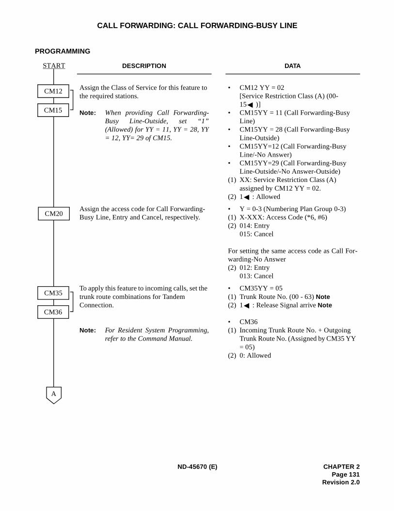
r-
CALL FORWARDING: CALL FORWARDING-BUSY LINE
PROGRAMMING
DESCRIPTION DATA
Assign the Class of Service for this feature to the required stations.
Note: When providing Call Forwarding-Busy Line-Outside, set “1”(Allowed) for YY = 11, YY = 28, YY= 12, YY= 29 of CM15.
• CM12 YY = 02[Service Restriction Class (A) (00-15 )]
• CM15YY = 11 (Call Forwarding-Busy Line)
• CM15YY = 28 (Call Forwarding-Busy Line-Outside)
• CM15YY=12 (Call Forwarding-Busy Line/-No Answer)
• CM15YY=29 (Call Forwarding-Busy Line-Outside/-No Answer-Outside)
(1) XX: Service Restriction Class (A) assigned by CM12 YY = 02.
(2) 1 : Allowed
Assign the access code for Call Forwarding-Busy Line, Entry and Cancel, respectively.
• Y = 0-3 (Numbering Plan Group 0-3)(1) X-XXX: Access Code (*6, #6)(2) 014: Entry
015: Cancel
For setting the same access code as Call Fowarding-No Answer(2) 012: Entry
013: Cancel
To apply this feature to incoming calls, set the trunk route combinations for Tandem Connection.
Note: For Resident System Programming,refer to the Command Manual.
• CM35YY = 05(1) Trunk Route No. (00 - 63) Note(2) 1 : Release Signal arrive Note
• CM36(1) Incoming Trunk Route No. + Outgoing
Trunk Route No. (Assigned by CM35 YY = 05)
(2) 0: Allowed
START
CM20
CM12
CM15
CM35
CM36
A
ND-45670 (E) CHAPTER 2Page 131
Revision 2.0
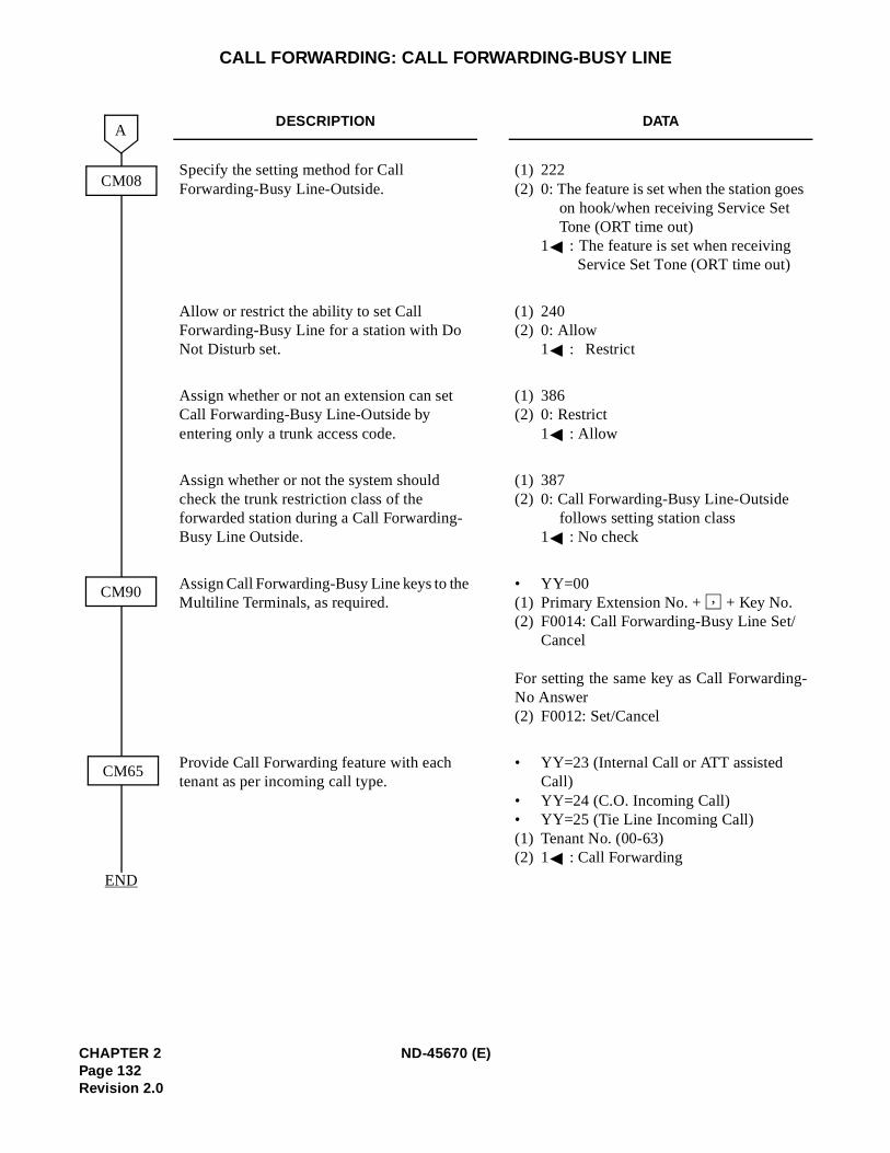
s
-
CALL FORWARDING: CALL FORWARDING-BUSY LINE
DESCRIPTION DATA
Specify the setting method for Call Forwarding-Busy Line-Outside.
(1) 222(2) 0: The feature is set when the station goe
on hook/when receiving Service Set Tone (ORT time out)
1 : The feature is set when receiving Service Set Tone (ORT time out)
Allow or restrict the ability to set Call Forwarding-Busy Line for a station with Do Not Disturb set.
(1) 240(2) 0: Allow
1 : Restrict
Assign whether or not an extension can set Call Forwarding-Busy Line-Outside by entering only a trunk access code.
(1) 386(2) 0: Restrict
1 : Allow
Assign whether or not the system should check the trunk restriction class of the forwarded station during a Call Forwarding- Busy Line Outside.
(1) 387(2) 0: Call Forwarding-Busy Line-Outside
follows setting station class1 : No check
Assign Call Forwarding-Busy Line keys to the Multiline Terminals, as required.
• YY=00(1) Primary Extension No. + + Key No.(2) F0014: Call Forwarding-Busy Line Set/
Cancel
For setting the same key as Call ForwardingNo Answer(2) F0012: Set/Cancel
Provide Call Forwarding feature with each tenant as per incoming call type.
• YY=23 (Internal Call or ATT assisted Call)
• YY=24 (C.O. Incoming Call)• YY=25 (Tie Line Incoming Call)(1) Tenant No. (00-63)(2) 1 : Call Forwarding
CM90
A
END
CM65
CM08
,
CHAPTER 2 ND-45670 (E)Page 132Revision 2.0
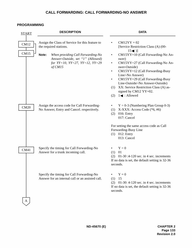
CALL FORWARDING: CALL FORWARDING-NO ANSWER
PROGRAMMING
DESCRIPTION DATA
Assign the Class of Service for this feature to the required stations.
Note: When providing Call Forwarding-NoAnswer-Outside, set “1” (Allowed)for YY=10, YY=27, YY=12, YY=29of CM15
• CM12YY = 02[Service Restriction Class (A) (00-
15 )]• CM15YY=10 (Call Forwarding-No An-
swer)• CM15YY=27 (Call Forwarding-No An-
swer-Outside)• CM15YY=12 (Call Forwarding-Busy
Line/-No Answer)• CM15YY=29 (Call Forwarding-Busy
Line-Outside/-No Answer-Outside)(1) XX: Service Restriction Class (A) as-
signed by CM12 YY=02.(2) 1 : Allowed
Assign the access code for Call Forwarding-No Answer, Entry and Cancel. respectively.
• Y = 0-3 (Numbering Plan Group 0-3)(1) X-XXX: Access Code (*6, #6)(2) 016: Entry
017: Cancel
For setting the same access code as Call Forwarding-Busy Line(1) 012: Entry
013: Cancel
Specify the timing for Call Forwarding-No Answer for a trunk incoming call.
• Y = 0(1) 01(2) 01-30 :4-120 sec. in 4 sec. incrementsIf no data is set, the default setting is 32-36 seconds.
Specify the timing for Call Forwarding-No Answer for an internal call or an assisted call.
• Y = 0 (1) 15(2) 01-30: 4-120 sec. in 4 sec. incrementsIf no data is set, the default setting is 32-36 seconds.
START
CM41
CM20
A
CM12
CM15
ND-45670 (E) CHAPTER 2Page 133
Revision 2.0
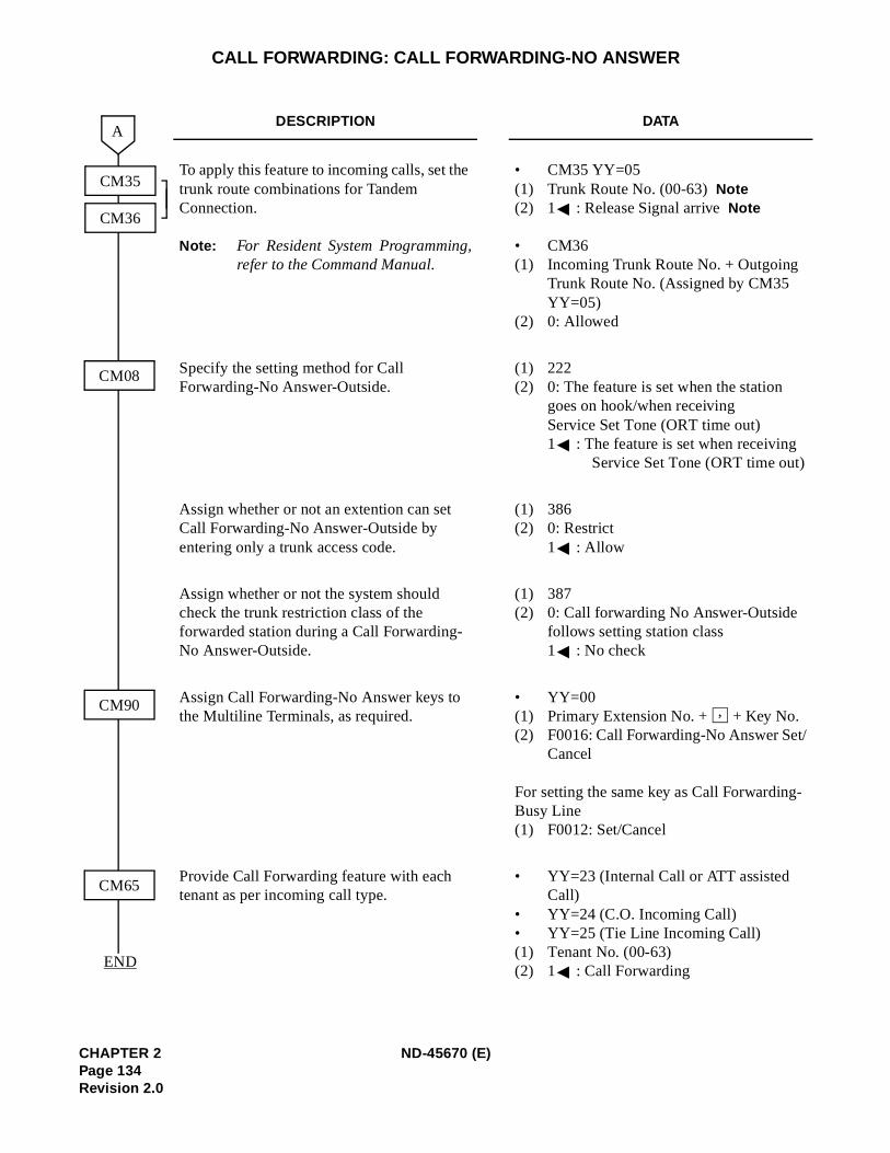
-
CALL FORWARDING: CALL FORWARDING-NO ANSWER
DESCRIPTION DATA
To apply this feature to incoming calls, set the trunk route combinations for Tandem Connection.
Note: For Resident System Programming,refer to the Command Manual.
• CM35 YY=05(1) Trunk Route No. (00-63)Note(2) 1 : Release Signal arriveNote
• CM36(1) Incoming Trunk Route No. + Outgoing
Trunk Route No. (Assigned by CM35 YY=05)
(2) 0: Allowed
Specify the setting method for Call Forwarding-No Answer-Outside.
(1) 222(2) 0: The feature is set when the station
goes on hook/when receiving Service Set Tone (ORT time out)1 : The feature is set when receiving
Service Set Tone (ORT time out)
Assign whether or not an extention can set Call Forwarding-No Answer-Outside by entering only a trunk access code.
(1) 386(2) 0: Restrict
1 : Allow
Assign whether or not the system should check the trunk restriction class of the forwarded station during a Call Forwarding-No Answer-Outside.
(1) 387(2) 0: Call forwarding No Answer-Outside
follows setting station class1 : No check
Assign Call Forwarding-No Answer keys to the Multiline Terminals, as required.
• YY=00(1) Primary Extension No. + + Key No.(2) F0016: Call Forwarding-No Answer Set/
Cancel
For setting the same key as Call ForwardingBusy Line(1) F0012: Set/Cancel
Provide Call Forwarding feature with each tenant as per incoming call type.
• YY=23 (Internal Call or ATT assisted Call)
• YY=24 (C.O. Incoming Call)• YY=25 (Tie Line Incoming Call)(1) Tenant No. (00-63)(2) 1 : Call Forwarding
A
CM08
CM65
CM35
CM36
CM90
END
,
CHAPTER 2 ND-45670 (E)Page 134Revision 2.0
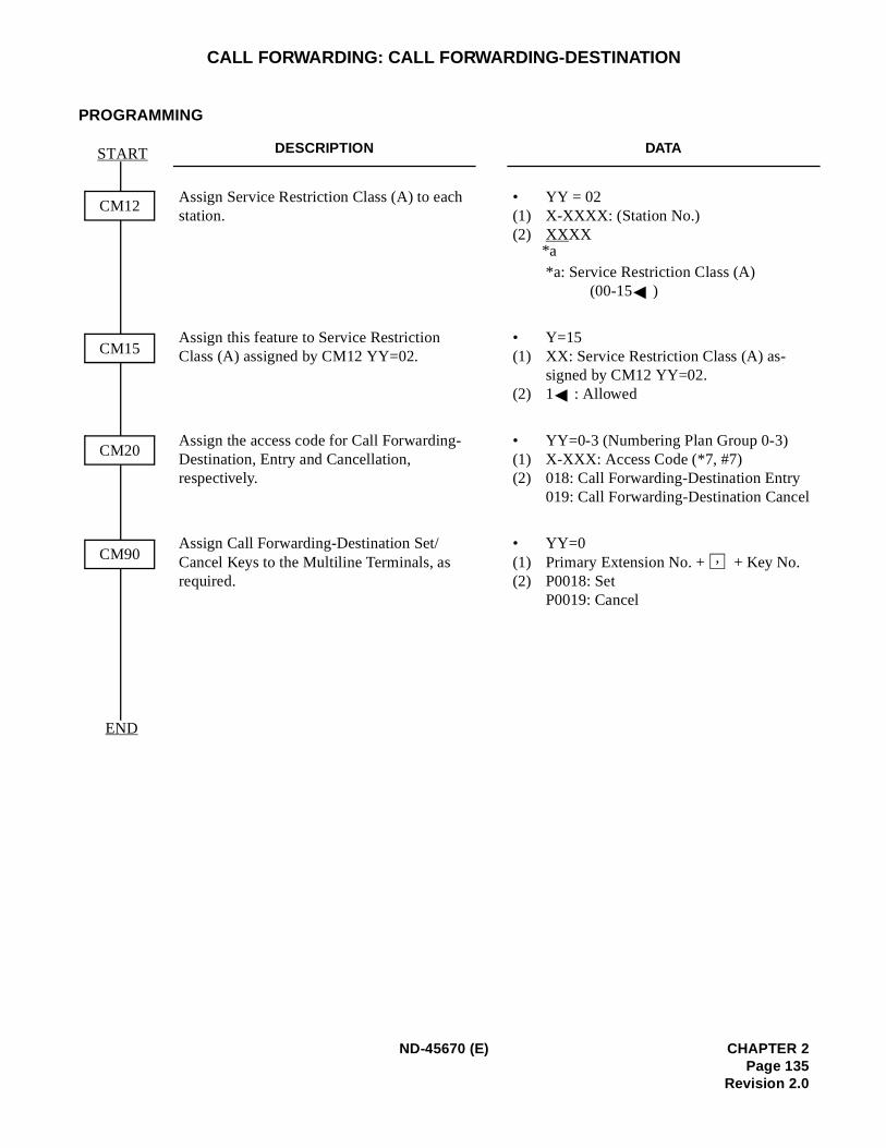
l
CALL FORWARDING: CALL FORWARDING-DESTINATION
PROGRAMMING
DESCRIPTION DATA
Assign Service Restriction Class (A) to each station.
• YY = 02(1) X-XXXX: (Station No.)(2) XXXX
*a: Service Restriction Class (A)(00-15 )
Assign this feature to Service Restriction Class (A) assigned by CM12 YY=02.
• Y=15(1) XX: Service Restriction Class (A) as-
signed by CM12 YY=02.(2) 1 : Allowed
Assign the access code for Call Forwarding-Destination, Entry and Cancellation, respectively.
• YY=0-3 (Numbering Plan Group 0-3)(1) X-XXX: Access Code (*7, #7)(2) 018: Call Forwarding-Destination Entry
019: Call Forwarding-Destination Cance
Assign Call Forwarding-Destination Set/Cancel Keys to the Multiline Terminals, as required.
• YY=0(1) Primary Extension No. + + Key No.(2) P0018: Set
P0019: Cancel
END
CM12
CM15
CM20
CM90
START
*a
,
ND-45670 (E) CHAPTER 2Page 135
Revision 2.0
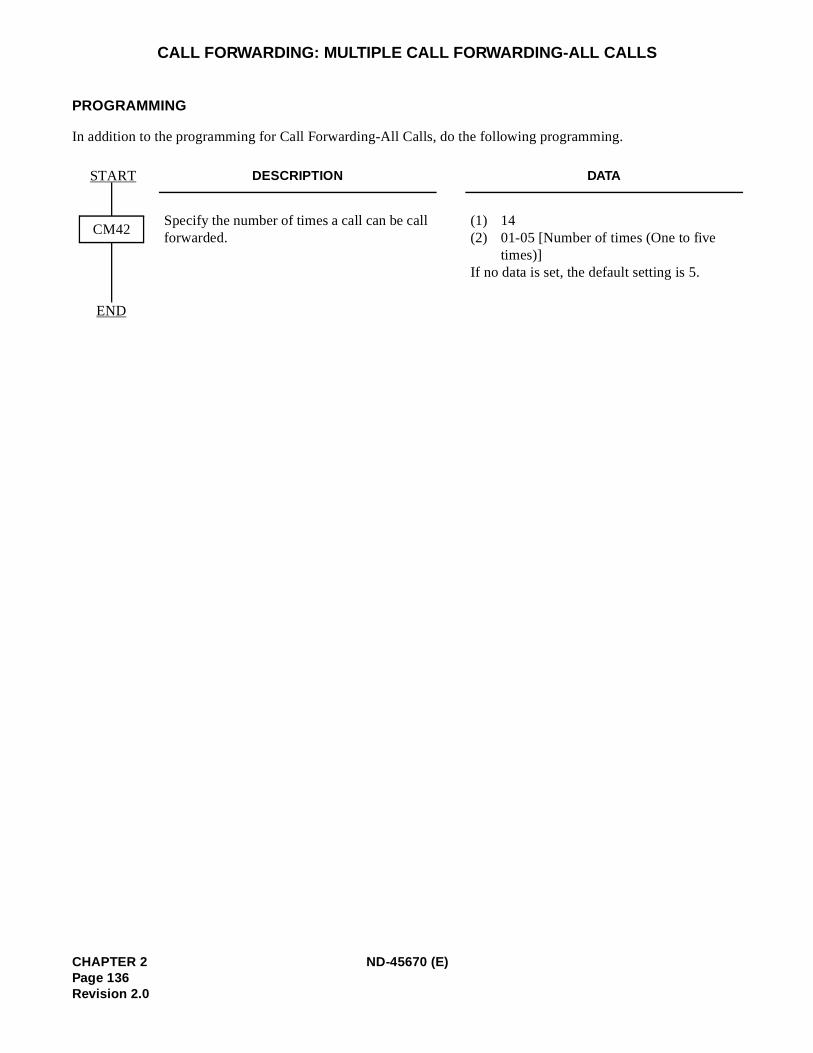
CALL FORWARDING: MULTIPLE CALL FORWARDING-ALL CALLS
PROGRAMMING
In addition to the programming for Call Forwarding-All Calls, do the following programming.
DESCRIPTION DATA
Specify the number of times a call can be call forwarded.
(1) 14(2) 01-05 [Number of times (One to five
times)]If no data is set, the default setting is 5.
CM42
END
START
CHAPTER 2 ND-45670 (E)Page 136Revision 2.0
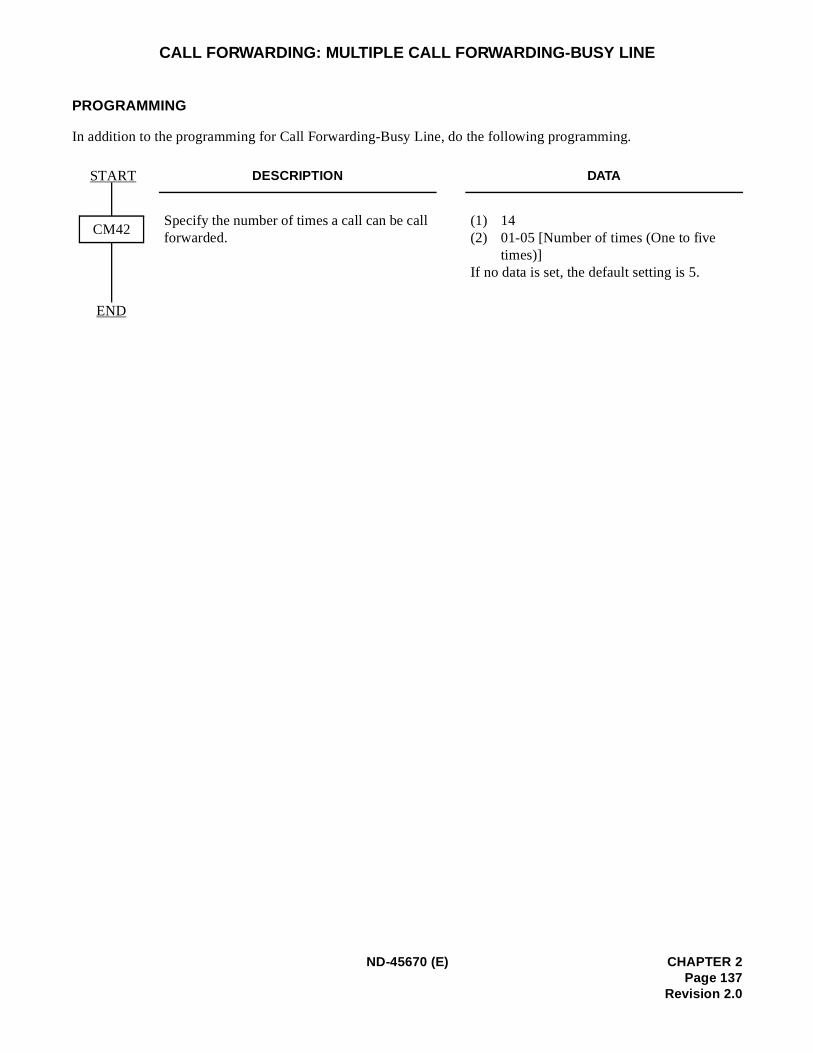
CALL FORWARDING: MULTIPLE CALL FORWARDING-BUSY LINE
PROGRAMMING
In addition to the programming for Call Forwarding-Busy Line, do the following programming.
DESCRIPTION DATA
Specify the number of times a call can be call forwarded.
(1) 14(2) 01-05 [Number of times (One to five
times)]If no data is set, the default setting is 5.
CM42
END
START
ND-45670 (E) CHAPTER 2Page 137
Revision 2.0
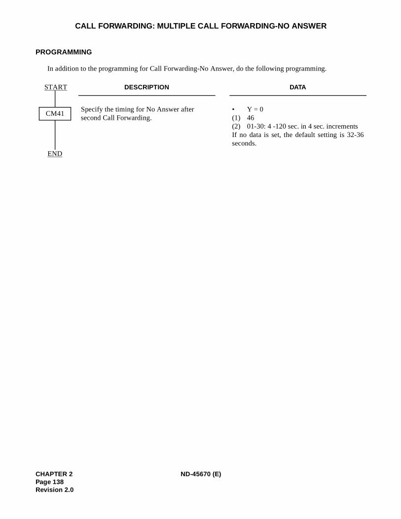
6
CALL FORWARDING: MULTIPLE CALL FORWARDING-NO ANSWER
PROGRAMMING
In addition to the programming for Call Forwarding-No Answer, do the following programming.
DESCRIPTION DATA
Specify the timing for No Answer after second Call Forwarding.
• Y = 0(1) 46(2) 01-30: 4 -120 sec. in 4 sec. incrementsIf no data is set, the default setting is 32-3seconds.
CM41
END
START
CHAPTER 2 ND-45670 (E)Page 138Revision 2.0
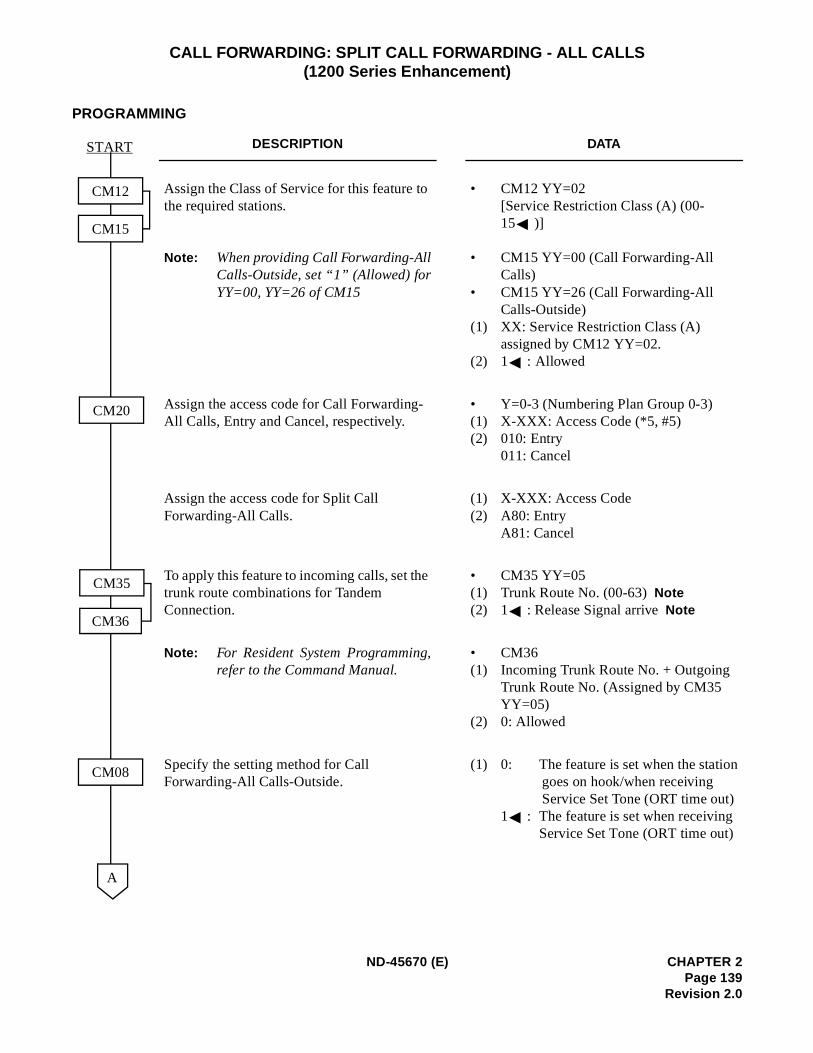
n
CALL FORWARDING: SPLIT CALL FORWARDING - ALL CALLS(1200 Series Enhancement)
PROGRAMMING
DESCRIPTION DATA
Assign the Class of Service for this feature to the required stations.
Note: When providing Call Forwarding-AllCalls-Outside, set “1” (Allowed) forYY=00, YY=26 of CM15
• CM12 YY=02 [Service Restriction Class (A) (00-15 )]
• CM15 YY=00 (Call Forwarding-AllCalls)
• CM15 YY=26 (Call Forwarding-AllCalls-Outside)
(1) XX: Service Restriction Class (A) assigned by CM12 YY=02.
(2) 1 : Allowed
Assign the access code for Call Forwarding-All Calls, Entry and Cancel, respectively.
• Y=0-3 (Numbering Plan Group 0-3)(1) X-XXX: Access Code (*5, #5)(2) 010: Entry
011: Cancel
Assign the access code for Split Call Forwarding-All Calls.
(1) X-XXX: Access Code(2) A80: Entry
A81: Cancel
To apply this feature to incoming calls, set the trunk route combinations for Tandem Connection.
• CM35 YY=05(1) Trunk Route No. (00-63)Note(2) 1 : Release Signal arriveNote
Note: For Resident System Programming,refer to the Command Manual.
• CM36(1) Incoming Trunk Route No. + Outgoing
Trunk Route No. (Assigned by CM35 YY=05)
(2) 0: Allowed
Specify the setting method for Call Forwarding-All Calls-Outside.
(1) 0: The feature is set when the statiogoes on hook/when receiving Service Set Tone (ORT time out)
1 : The feature is set when receivingService Set Tone (ORT time out)
CM12
CM15
CM20
CM35
CM36
A
CM08
START
ND-45670 (E) CHAPTER 2Page 139
Revision 2.0
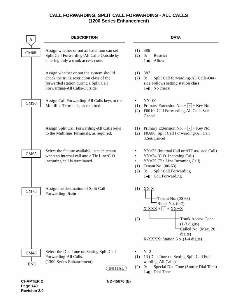
)
)
CALL FORWARDING: SPLIT CALL FORWARDING - ALL CALLS(1200 Series Enhancement)
DESCRIPTION DATA
Assign whether or not an extention can set Split Call Forwarding-All Calls-Outside by entering only a trunk access code.
(1) 386(2) 0: Restrict
1 : Allow
Assign whether or not the system should check the trunk restriction class of the forwarded station during a Split Call Forwarding-All Calls-Outside.
(1) 387(2) 0: Split Call forwarding-All Calls-Out-
side Follows setting station class1 : No check
Assign Call Forwarding-All Calls keys to the Multiline Terminals, as required.
• YY=00(1) Primary Extension No. + + Key No.(2) F0010: Call Forwarding-All Calls Set/
Cancel
Assign Split Call Forwarding-All Calls keys to the Multiline Terminals, as required.
(1) Primary Extension No. + + Key No.(2) F0A80: Split Call Forwarding-All Call
3.Set/Cancel
Select the feature available in each tenant when an internal call and a Tie Line/C.O.incoming call is terminated.
• YY=23 (Internal Call or ATT assisted Call• YY=24 (C.O. Incoming Call)• YY=25 (Tie Line Incoming Call)(1) Tenant No. (00-63)(2) 0: Split Call Forwarding
1 : Call Forwarding
Assign the destination of Split Call Forwarding. Note
(1) XX X
Tenant No. (00-63)Block No. (0-7)
X-XXX + + XX···X
(2) Trunk Access Code(1-3 digits)Called No. (Max. 26digits)
X-XXXX: Station No. (1-4 digits)
Select the Dial Tone on Setting Split Call Forwarding-All Calls. (1300 Series Enhancement)
• Y=2(1) 13 (Dial Tone on Setting Split Call For-
warding-All Calls)(2) 0: Special Dial Tone (Stutter Dial Tone
1 : Dial Tone
CM08
CM90
CM65
CM78
A
CM48
END
,
,
,
INITIAL
CHAPTER 2 ND-45670 (E)Page 140Revision 2.0
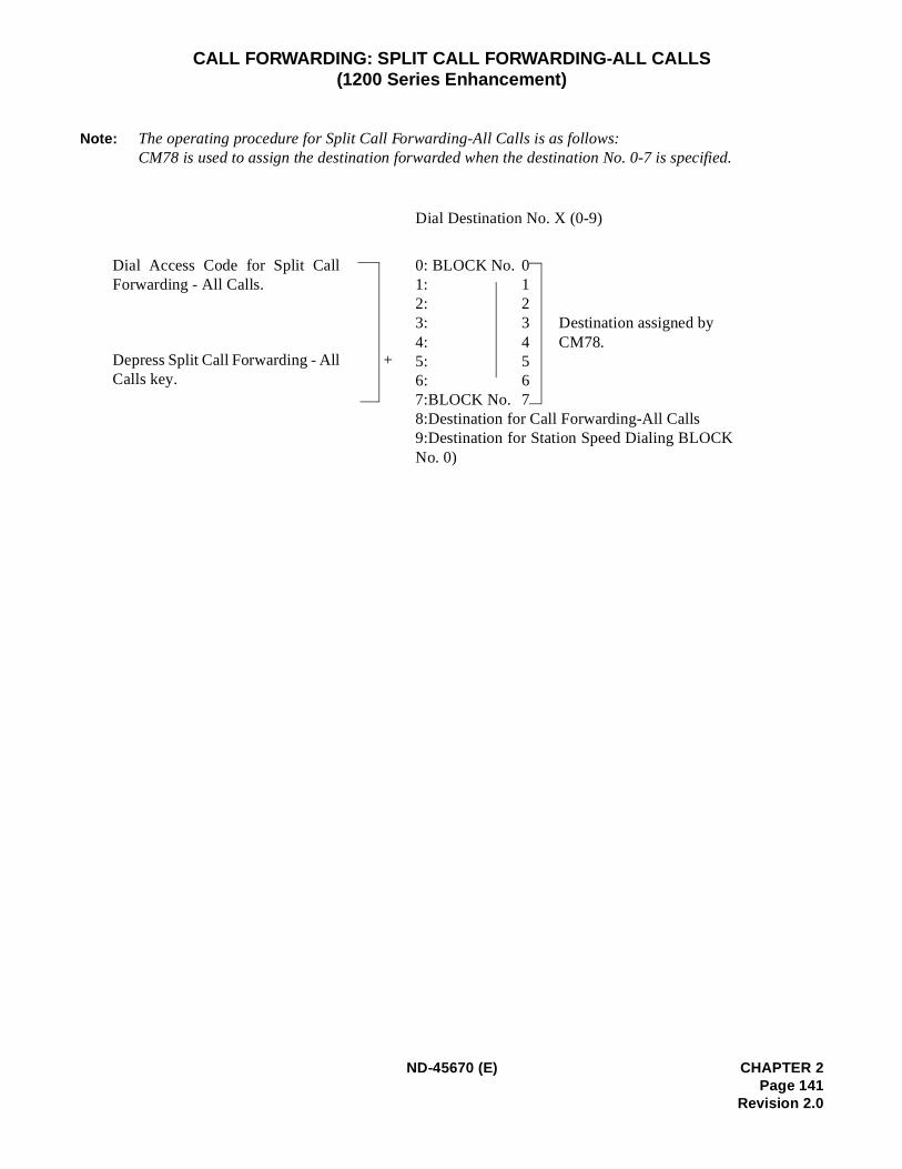
CALL FORWARDING: SPLIT CALL FORWARDING-ALL CALLS(1200 Series Enhancement)
Note: The operating procedure for Split Call Forwarding-All Calls is as follows:CM78 is used to assign the destination forwarded when the destination No. 0-7 is specified.
Dial Destination No. X (0-9)
Dial Access Code for Split CallForwarding - All Calls.
0: BLOCK No. 01: 12: 23: 3 Destination assigned by4: 4 CM78.5: 56: 67:BLOCK No. 78:Destination for Call Forwarding-All Calls9:Destination for Station Speed Dialing BLOCKNo. 0)
Depress Split Call Forwarding - AllCalls key.
+
ND-45670 (E) CHAPTER 2Page 141
Revision 2.0
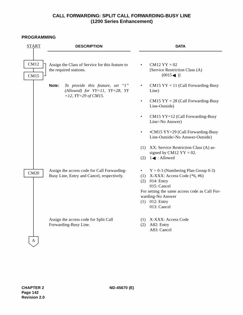
r-
CALL FORWARDING: SPLIT CALL FORWARDING-BUSY LINE(1200 Series Enhancement)
PROGRAMMING
DESCRIPTION DATA
Assign the Class of Service for this feature to the required stations.
Note: To provide this feature, set “1”(Allowed) for YY=11, YY=28, YY=12, YY=29 of CM15.
• CM12 YY = 02[Service Restriction Class (A)
(0015 )]
• CM15 YY = 11 (Call Forwarding-Busy Line)
• CM15 YY = 28 (Call Forwarding-Busy Line-Outside)
• CM15 YY=12 (Call Forwarding-Busy Line/-No Answer)
• •CM15 YY=29 (Call Forwarding-Busy Line-Outside/-No Answer-Outside)
(1) XX: Service Restriction Class (A) as-signed by CM12 YY = 02.
(2) 1 : Allowed
Assign the access code for Call Forwarding-Busy Line, Entry and Cancel, respectively.
• Y = 0-3 (Numbering Plan Group 0-3)(1) X-XXX: Access Code (*6, #6)(2) 014: Entry
015: CancelFor setting the same access code as Call Fowarding-No Answer(1) 012: Entry
013: Cancel
Assign the access code for Split Call Forwarding-Busy Line.
(1) X-XXX: Access Code(2) A82: Entry
A83: Cancel
START
CM20
A
CM12
CM15
CHAPTER 2 ND-45670 (E)Page 142Revision 2.0
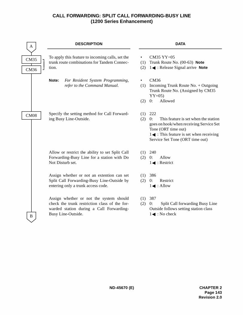
t
CALL FORWARDING: SPLIT CALL FORWARDING-BUSY LINE(1200 Series Enhancement)
DESCRIPTION DATA
To apply this feature to incoming calls, set thetrunk route combinations for Tandem Connec-tion.
• CM35 YY=05(1) Trunk Route No. (00-63)Note(2) 1 : Release Signal arriveNote
Note: For Resident System Programming,refer to the Command Manual.
• CM36(1) Incoming Trunk Route No. + Outgoing
Trunk Route No. (Assigned by CM35 YY=05)
(2) 0: Allowed
Specify the setting method for Call Forward-ing Busy Line-Outside.
(1) 222(2) 0: This feature is set when the station
goes on hook/when receiving Service SeTone (ORT time out)1 : This feature is set when receivingService Set Tone (ORT time out)
Allow or restrict the ability to set Split CallForwarding-Busy Line for a station with DoNot Disturb set.
(1) 240(2) 0: Allow
1 : Restrict
Assign whether or not an extention can setSplit Call Forwarding-Busy Line-Outside byentering only a trunk access code.
(1) 386(2) 0: Restrict
1 : Allow
Assign whether or not the system shouldcheck the trunk restriction class of the for-warded station during a Call Forwarding-Busy Line-Outside.
(1) 387(2) 0: Split Call forwarding Busy Line
Outside follows setting station class1 : No check
CM35
A
B
CM36
CM08
ND-45670 (E) CHAPTER 2Page 143
Revision 2.0
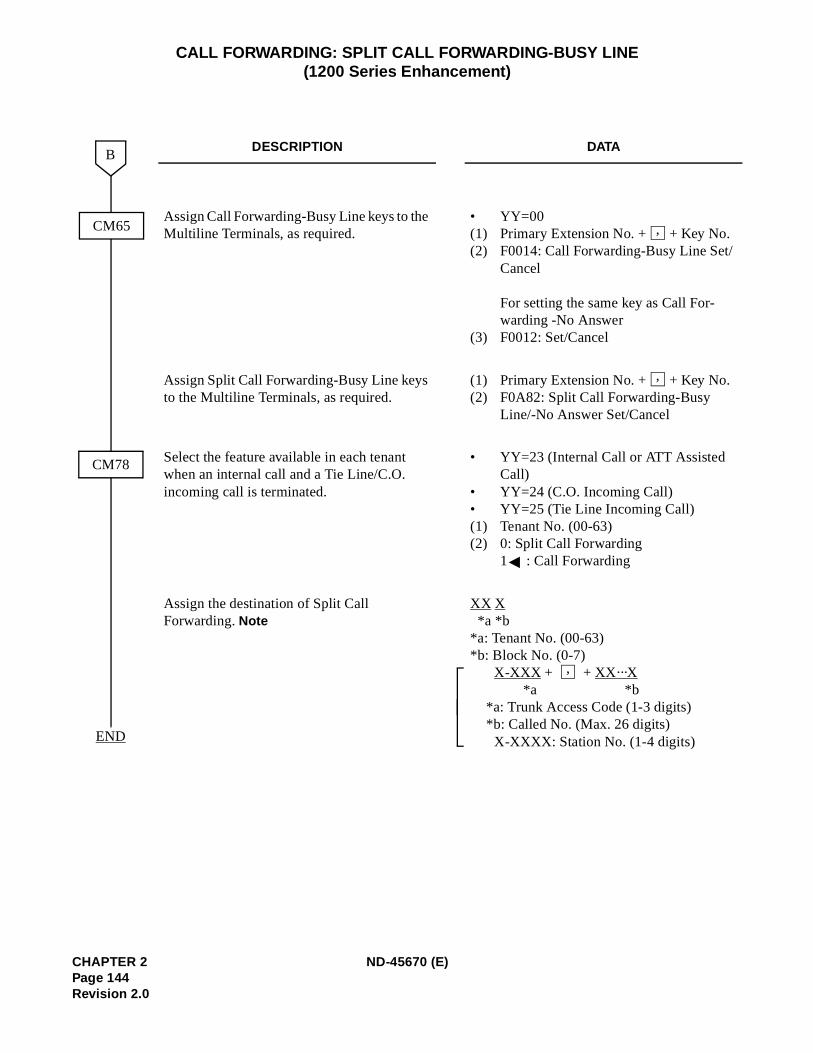
CALL FORWARDING: SPLIT CALL FORWARDING-BUSY LINE(1200 Series Enhancement)
DESCRIPTION DATA
Assign Call Forwarding-Busy Line keys to the Multiline Terminals, as required.
• YY=00(1) Primary Extension No. + + Key No.(2) F0014: Call Forwarding-Busy Line Set/
Cancel
For setting the same key as Call For-warding -No Answer
(3) F0012: Set/Cancel
Assign Split Call Forwarding-Busy Line keys to the Multiline Terminals, as required.
(1) Primary Extension No. + + Key No.(2) F0A82: Split Call Forwarding-Busy
Line/-No Answer Set/Cancel
Select the feature available in each tenant when an internal call and a Tie Line/C.O. incoming call is terminated.
• YY=23 (Internal Call or ATT Assisted Call)
• YY=24 (C.O. Incoming Call)• YY=25 (Tie Line Incoming Call)(1) Tenant No. (00-63)(2) 0: Split Call Forwarding
1 : Call Forwarding
Assign the destination of Split Call Forwarding. Note
XX X*a *b
*a: Tenant No. (00-63)*b: Block No. (0-7)
X-XXX + + XX···X*a *b
*a: Trunk Access Code (1-3 digits)*b: Called No. (Max. 26 digits)X-XXXX: Station No. (1-4 digits)
CM78
B
END
CM65 ,
,
,
CHAPTER 2 ND-45670 (E)Page 144Revision 2.0
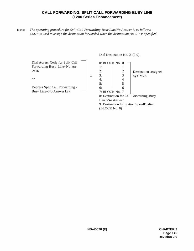
CALL FORWARDING: SPLIT CALL FORWARDING-BUSY LINE(1200 Series Enhancement)
Note: The operating procedure for Split Call Forwarding-Busy Line/No Answer is as follows:CM78 is used to assign the destination forwarded when the destination No. 0-7 is specified.
Dial Destination No. X (0-9).
0: BLOCK No. 01: 12: 23: 34: 45: 56: 67: BLOCK No. 78: Destination for Call Forwarding-BusyLine/-No Answer9: Destination for Station SpeedDialing(BLOCK No. 0)
+
Dial Access Code for Split CallForwarding-Busy Line/-No An-swer.
or
Depress Split Call Forwarding -Busy Line/-No Answer key.
Destination assignedby CM78.
ND-45670 (E) CHAPTER 2Page 145
Revision 2.0
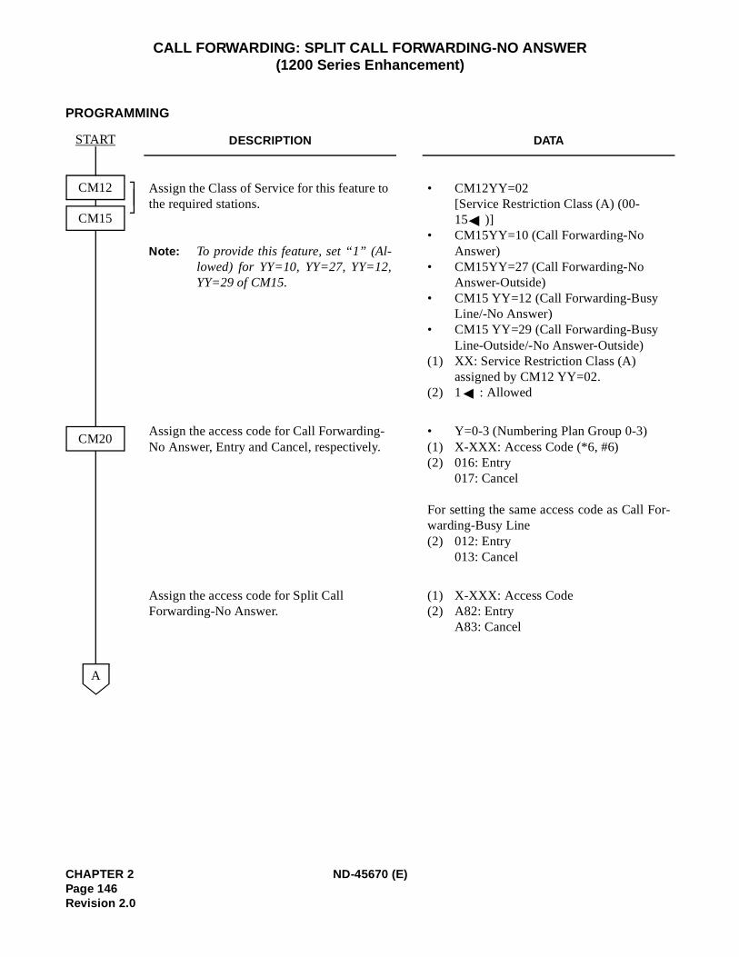
r-
CALL FORWARDING: SPLIT CALL FORWARDING-NO ANSWER(1200 Series Enhancement)
PROGRAMMING
DESCRIPTION DATA
Assign the Class of Service for this feature to the required stations.
Note: To provide this feature, set “1” (Al-lowed) for YY=10, YY=27, YY=12,YY=29 of CM15.
• CM12YY=02 [Service Restriction Class (A) (00-15 )]
• CM15YY=10 (Call Forwarding-No Answer)
• CM15YY=27 (Call Forwarding-No Answer-Outside)
• CM15 YY=12 (Call Forwarding-Busy Line/-No Answer)
• CM15 YY=29 (Call Forwarding-Busy Line-Outside/-No Answer-Outside)
(1) XX: Service Restriction Class (A) assigned by CM12 YY=02.
(2) 1 : Allowed
Assign the access code for Call Forwarding-No Answer, Entry and Cancel, respectively.
• Y=0-3 (Numbering Plan Group 0-3)(1) X-XXX: Access Code (*6, #6)(2) 016: Entry
017: Cancel
For setting the same access code as Call Fowarding-Busy Line(2) 012: Entry
013: Cancel
Assign the access code for Split Call Forwarding-No Answer.
(1) X-XXX: Access Code (2) A82: Entry
A83: Cancel
START
CM12
CM15
CM20
A
CHAPTER 2 ND-45670 (E)Page 146Revision 2.0
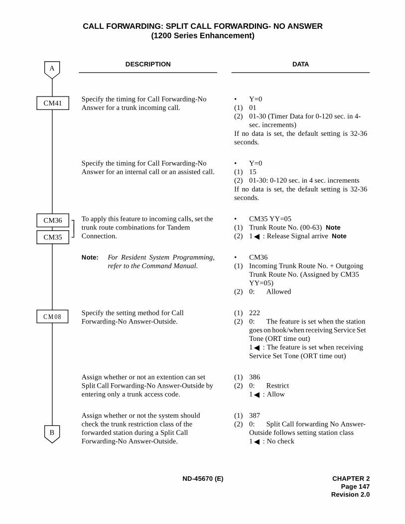
6
6
t
CALL FORWARDING: SPLIT CALL FORWARDING- NO ANSWER(1200 Series Enhancement)
DESCRIPTION DATA
Specify the timing for Call Forwarding-No Answer for a trunk incoming call.
• Y=0(1) 01(2) 01-30 (Timer Data for 0-120 sec. in 4-
sec. increments)If no data is set, the default setting is 32-3seconds.
Specify the timing for Call Forwarding-No Answer for an internal call or an assisted call.
• Y=0(1) 15(2) 01-30: 0-120 sec. in 4 sec. incrementsIf no data is set, the default setting is 32-3seconds.
To apply this feature to incoming calls, set the trunk route combinations for Tandem Connection.
• CM35 YY=05(1) Trunk Route No. (00-63)Note(2) 1 : Release Signal arriveNote
Note: For Resident System Programming,refer to the Command Manual.
• CM36(1) Incoming Trunk Route No. + Outgoing
Trunk Route No. (Assigned by CM35 YY=05)
(2) 0: Allowed
Specify the setting method for Call Forwarding-No Answer-Outside.
(1) 222(2) 0: The feature is set when the station
goes on hook/when receiving Service SeTone (ORT time out)1 : The feature is set when receiving Service Set Tone (ORT time out)
Assign whether or not an extention can set Split Call Forwarding-No Answer-Outside by entering only a trunk access code.
(1) 386(2) 0: Restrict
1 : Allow
Assign whether or not the system should check the trunk restriction class of the forwarded station during a Split Call Forwarding-No Answer-Outside.
(1) 387(2) 0: Split Call forwarding No Answer-
Outside follows setting station class1 : No check
CM41
A
B
CM36
CM35
C M 08
ND-45670 (E) CHAPTER 2Page 147
Revision 2.0
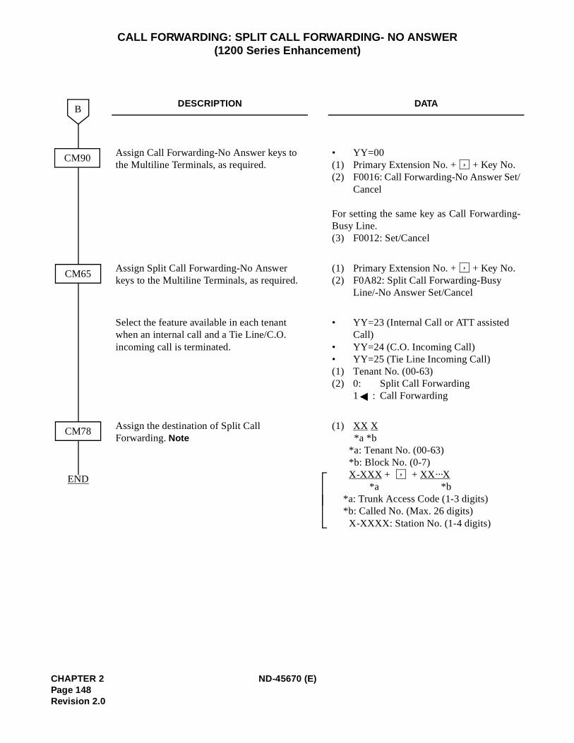
-
CALL FORWARDING: SPLIT CALL FORWARDING- NO ANSWER(1200 Series Enhancement)
DESCRIPTION DATA
Assign Call Forwarding-No Answer keys to the Multiline Terminals, as required.
• YY=00(1) Primary Extension No. + + Key No.(2) F0016: Call Forwarding-No Answer Set/
Cancel
For setting the same key as Call ForwardingBusy Line.(3) F0012: Set/Cancel
Assign Split Call Forwarding-No Answer keys to the Multiline Terminals, as required.
(1) Primary Extension No. + + Key No.(2) F0A82: Split Call Forwarding-Busy
Line/-No Answer Set/Cancel
Select the feature available in each tenant when an internal call and a Tie Line/C.O. incoming call is terminated.
• YY=23 (Internal Call or ATT assisted Call)
• YY=24 (C.O. Incoming Call)• YY=25 (Tie Line Incoming Call)(1) Tenant No. (00-63)(2) 0: Split Call Forwarding
1 : Call Forwarding
Assign the destination of Split Call Forwarding. Note
(1) XX X*a *b
*a: Tenant No. (00-63)*b: Block No. (0-7)X-XXX + + XX···X
*a *b*a: Trunk Access Code (1-3 digits)*b: Called No. (Max. 26 digits)X-XXXX: Station No. (1-4 digits)
CM78
B
END
CM65
CM90 ,
,
,
CHAPTER 2 ND-45670 (E)Page 148Revision 2.0
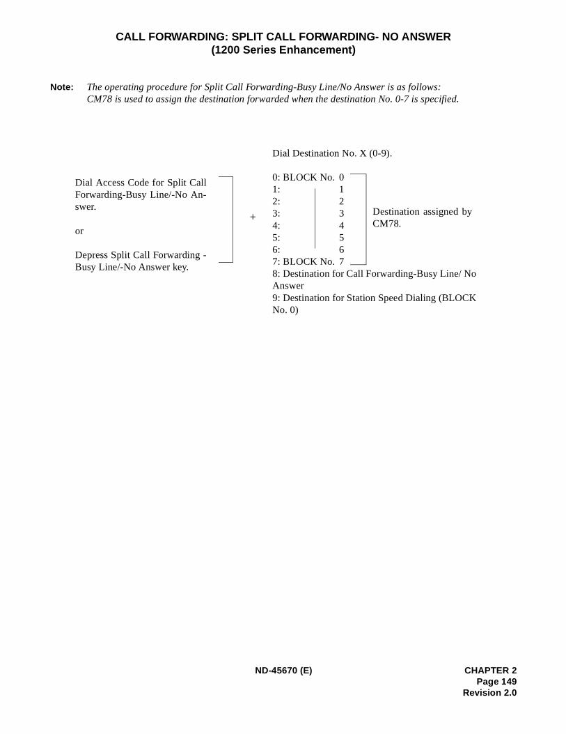
CALL FORWARDING: SPLIT CALL FORWARDING- NO ANSWER(1200 Series Enhancement)
Note: The operating procedure for Split Call Forwarding-Busy Line/No Answer is as follows:CM78 is used to assign the destination forwarded when the destination No. 0-7 is specified.
Dial Destination No. X (0-9).
0: BLOCK No. 01: 12: 23: 34: 45: 56: 67: BLOCK No. 78: Destination for Call Forwarding-Busy Line/ NoAnswer9: Destination for Station Speed Dialing (BLOCKNo. 0)
+
Dial Access Code for Split CallForwarding-Busy Line/-No An-swer.
or
Depress Split Call Forwarding -Busy Line/-No Answer key.
Destination assigned byCM78.
ND-45670 (E) CHAPTER 2Page 149
Revision 2.0
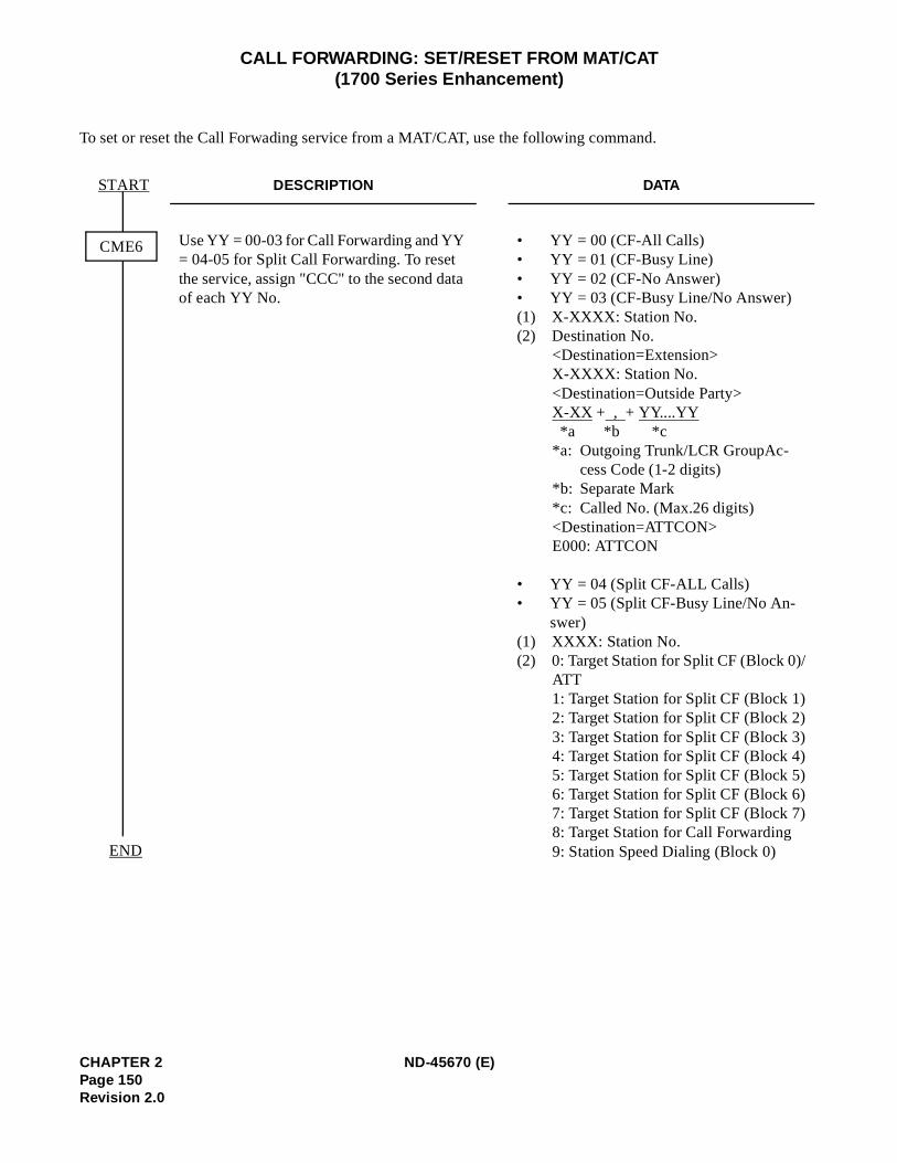
CALL FORWARDING: SET/RESET FROM MAT/CAT(1700 Series Enhancement)
To set or reset the Call Forwading service from a MAT/CAT, use the following command.
DESCRIPTION DATA
Use YY = 00-03 for Call Forwarding and YY = 04-05 for Split Call Forwarding. To reset the service, assign "CCC" to the second data of each YY No.
• YY = 00 (CF-All Calls) • YY = 01 (CF-Busy Line) • YY = 02 (CF-No Answer) • YY = 03 (CF-Busy Line/No Answer) (1) X-XXXX: Station No.(2) Destination No.
<Destination=Extension>X-XXXX: Station No.<Destination=Outside Party>X-XX + , + YY....YY*a *b *c
*a: Outgoing Trunk/LCR GroupAc-cess Code (1-2 digits)
*b: Separate Mark*c: Called No. (Max.26 digits)<Destination=ATTCON>E000: ATTCON
• YY = 04 (Split CF-ALL Calls)• YY = 05 (Split CF-Busy Line/No An-
swer)(1) XXXX: Station No.(2) 0: Target Station for Split CF (Block 0)/
ATT1: Target Station for Split CF (Block 1)2: Target Station for Split CF (Block 2)3: Target Station for Split CF (Block 3)4: Target Station for Split CF (Block 4)5: Target Station for Split CF (Block 5)6: Target Station for Split CF (Block 6)7: Target Station for Split CF (Block 7)8: Target Station for Call Forwarding 9: Station Speed Dialing (Block 0)
CME6
START
END
CHAPTER 2 ND-45670 (E)Page 150Revision 2.0
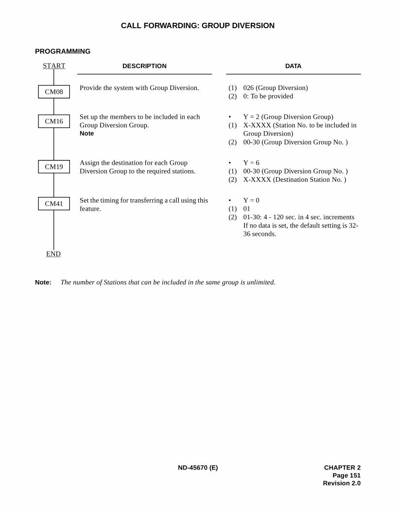
-
CALL FORWARDING: GROUP DIVERSION
PROGRAMMING
Note: The number of Stations that can be included in the same group is unlimited.
DESCRIPTION DATA
Provide the system with Group Diversion. (1) 026 (Group Diversion)(2) 0: To be provided
Set up the members to be included in each Group Diversion Group.Note
• Y = 2 (Group Diversion Group)(1) X-XXXX (Station No. to be included in
Group Diversion)(2) 00-30 (Group Diversion Group No. )
Assign the destination for each Group Diversion Group to the required stations.
• Y = 6(1) 00-30 (Group Diversion Group No. )(2) X-XXXX (Destination Station No. )
Set the timing for transferring a call using this feature.
• Y = 0(1) 01(2) 01-30: 4 - 120 sec. in 4 sec. increments
If no data is set, the default setting is 3236 seconds.
START
CM41
CM08
END
CM16
CM19
ND-45670 (E) CHAPTER 2Page 151
Revision 2.0
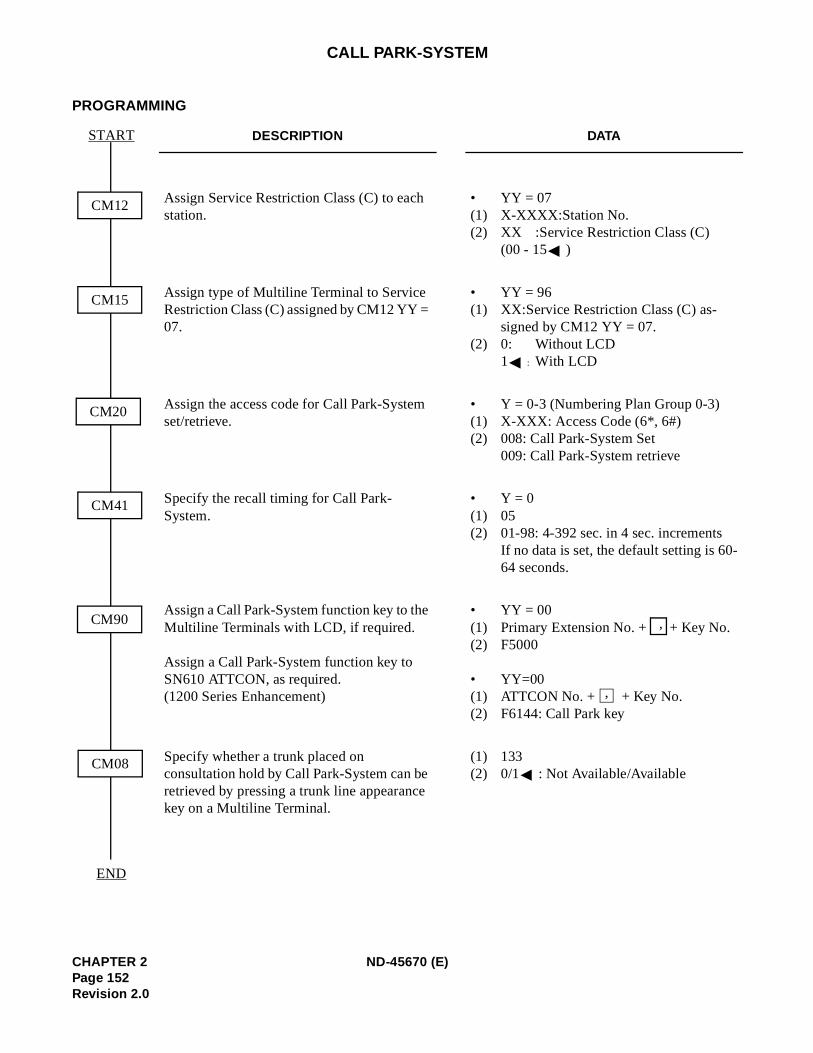
-
CALL PARK-SYSTEM
PROGRAMMING
DESCRIPTION DATA
Assign Service Restriction Class (C) to each station.
• YY = 07(1) X-XXXX:Station No. (2) XX :Service Restriction Class (C)
(00 - 15 )
Assign type of Multiline Terminal to Service Restriction Class (C) assigned by CM12 YY = 07.
• YY = 96(1) XX:Service Restriction Class (C) as-
signed by CM12 YY = 07.(2) 0: Without LCD
1 : With LCD
Assign the access code for Call Park-System set/retrieve.
• Y = 0-3 (Numbering Plan Group 0-3)(1) X-XXX: Access Code (6*, 6#)(2) 008: Call Park-System Set
009: Call Park-System retrieve
Specify the recall timing for Call Park-System.
• Y = 0(1) 05(2) 01-98: 4-392 sec. in 4 sec. increments
If no data is set, the default setting is 6064 seconds.
Assign a Call Park-System function key to the Multiline Terminals with LCD, if required.
Assign a Call Park-System function key to SN610 ATTCON, as required. (1200 Series Enhancement)
• YY = 00(1) Primary Extension No. + + Key No.(2) F5000
• YY=00(1) ATTCON No. + + Key No.(2) F6144: Call Park key
Specify whether a trunk placed on consultation hold by Call Park-System can be retrieved by pressing a trunk line appearance key on a Multiline Terminal.
(1) 133(2) 0/1 : Not Available/Available
START
CM41
CM12
END
CM15
CM20
CM90
CM08
,
,
CHAPTER 2 ND-45670 (E)Page 152Revision 2.0
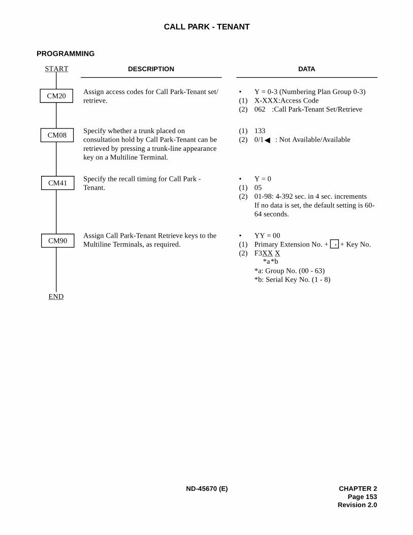
-
CALL PARK - TENANT
PROGRAMMING
DESCRIPTION DATA
Assign access codes for Call Park-Tenant set/retrieve.
• Y = 0-3 (Numbering Plan Group 0-3)(1) X-XXX:Access Code(2) 062 :Call Park-Tenant Set/Retrieve
Specify whether a trunk placed on consultation hold by Call Park-Tenant can be retrieved by pressing a trunk-line appearance key on a Multiline Terminal.
(1) 133(2) 0/1 : Not Available/Available
Specify the recall timing for Call Park - Tenant.
• Y = 0(1) 05(2) 01-98: 4-392 sec. in 4 sec. increments
If no data is set, the default setting is 6064 seconds.
Assign Call Park-Tenant Retrieve keys to the Multiline Terminals, as required.
• YY = 00(1) Primary Extension No. + + Key No. (2) F3XX X
*a: Group No. (00 - 63)*b: Serial Key No. (1 - 8)
START
CM90
CM20
END
CM08
CM41
,
*b*a
ND-45670 (E) CHAPTER 2Page 153
Revision 2.0
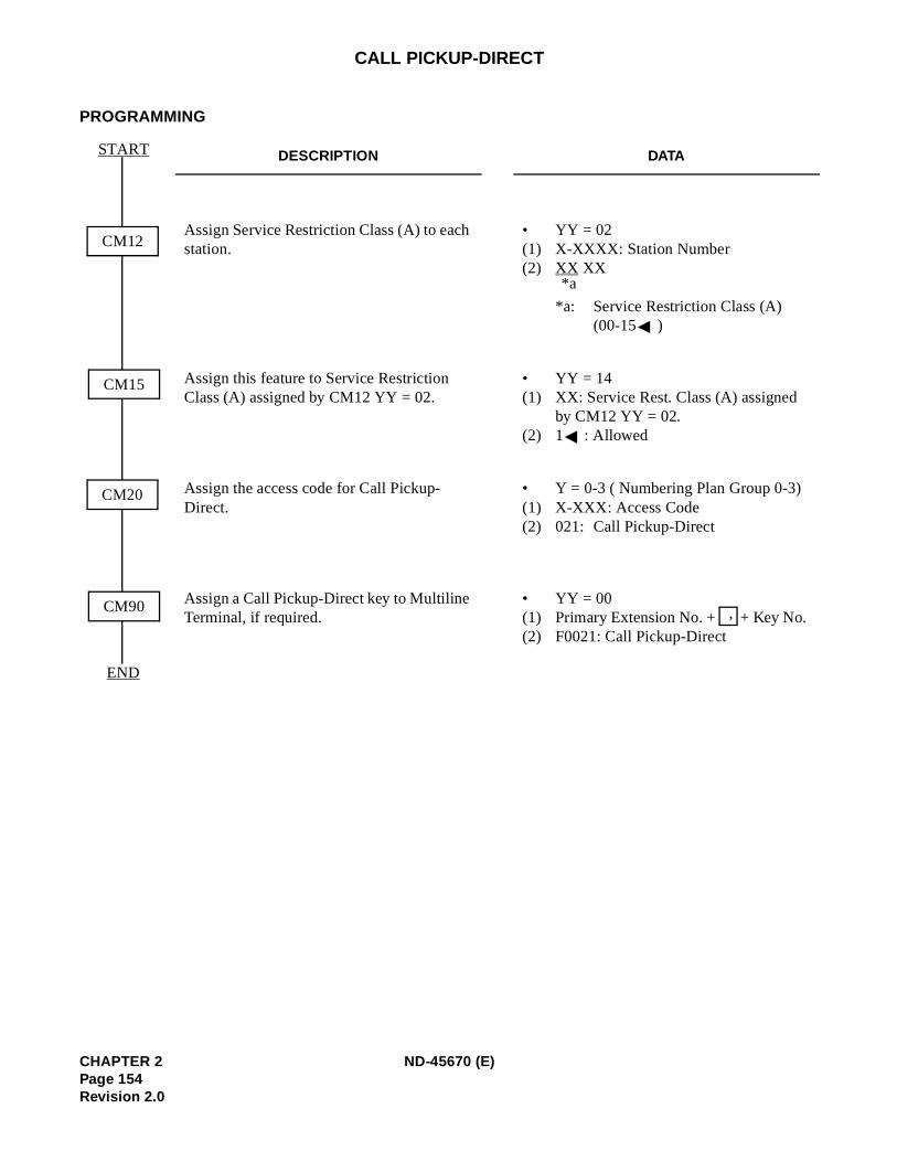
CALL PICKUP-DIRECT
PROGRAMMING
DESCRIPTION DATA
Assign Service Restriction Class (A) to each station.
• YY = 02(1) X-XXXX: Station Number(2) XX XX
*a: Service Restriction Class (A)(00-15 )
Assign this feature to Service Restriction Class (A) assigned by CM12 YY = 02.
• YY = 14(1) XX: Service Rest. Class (A) assigned
by CM12 YY = 02.(2) 1 : Allowed
Assign the access code for Call Pickup-Direct.
• Y = 0-3 ( Numbering Plan Group 0-3)(1) X-XXX: Access Code(2) 021: Call Pickup-Direct
Assign a Call Pickup-Direct key to Multiline Terminal, if required.
• YY = 00(1) Primary Extension No. + + Key No. (2) F0021: Call Pickup-Direct
START
CM90
CM12
END
CM15
CM20
*a
,
CHAPTER 2 ND-45670 (E)Page 154Revision 2.0
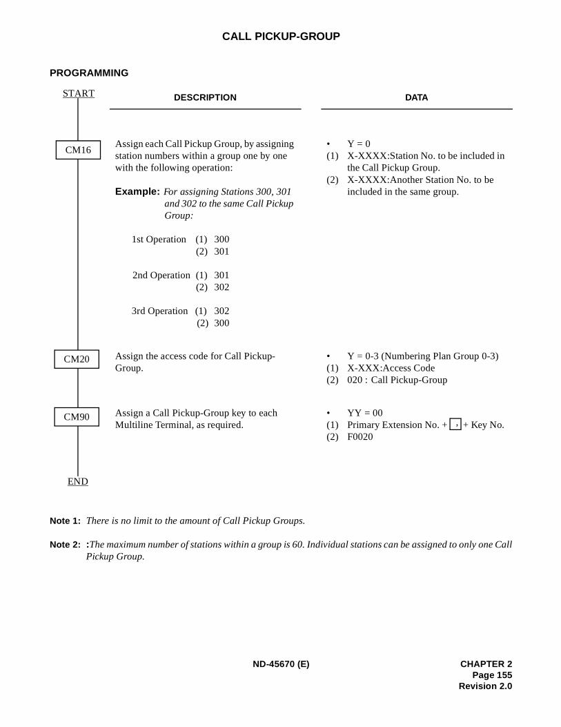
ne Call
CALL PICKUP-GROUP
PROGRAMMING
Note 1: There is no limit to the amount of Call Pickup Groups.
Note 2: :The maximum number of stations within a group is 60. Individual stations can be assigned to only oPickup Group.
DESCRIPTION DATA
Assign each Call Pickup Group, by assigning station numbers within a group one by one with the following operation:
Example: For assigning Stations 300, 301 and 302 to the same Call Pickup Group:
1st Operation (1) 300(2) 301
2nd Operation (1) 301(2) 302
3rd Operation (1) 302(2) 300
• Y = 0(1) X-XXXX:Station No. to be included in
the Call Pickup Group. (2) X-XXXX:Another Station No. to be
included in the same group.
Assign the access code for Call Pickup-Group.
• Y = 0-3 (Numbering Plan Group 0-3)(1) X-XXX:Access Code(2) 020 : Call Pickup-Group
Assign a Call Pickup-Group key to each Multiline Terminal, as required.
• YY = 00(1) Primary Extension No. + + Key No. (2) F0020
START
CM16
END
CM20
CM90 ,
ND-45670 (E) CHAPTER 2Page 155
Revision 2.0
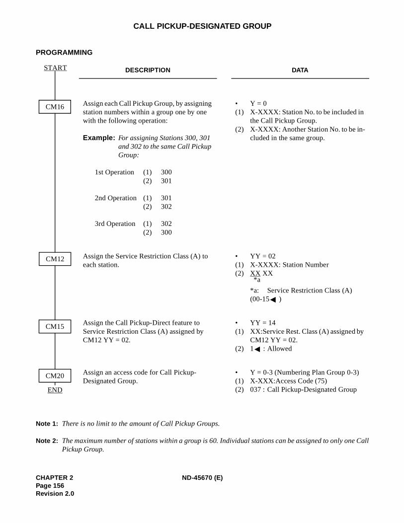
ne Call
CALL PICKUP-DESIGNATED GROUP
PROGRAMMING
Note 1: There is no limit to the amount of Call Pickup Groups.
Note 2: The maximum number of stations within a group is 60. Individual stations can be assigned to only oPickup Group.
DESCRIPTION DATA
Assign each Call Pickup Group, by assigning station numbers within a group one by one with the following operation:
Example: For assigning Stations 300, 301 and 302 to the same Call Pickup Group:
1st Operation (1) 300 (2) 301
2nd Operation (1) 301(2) 302
3rd Operation (1) 302(2) 300
• Y = 0(1) X-XXXX: Station No. to be included in
the Call Pickup Group.(2) X-XXXX: Another Station No. to be in-
cluded in the same group.
Assign the Service Restriction Class (A) to each station.
• YY = 02(1) X-XXXX: Station Number(2) XX XX
*a: Service Restriction Class (A) (00-15 )
Assign the Call Pickup-Direct feature to Service Restriction Class (A) assigned by CM12 YY = 02.
• YY = 14(1) XX:Service Rest. Class (A) assigned by
CM12 YY = 02. (2) 1 : Allowed
Assign an access code for Call Pickup-Designated Group.
• Y = 0-3 (Numbering Plan Group 0-3) (1) X-XXX:Access Code (75)(2) 037 : Call Pickup-Designated Group
CM16
CM15
START
CM20
END
CM12
*a
CHAPTER 2 ND-45670 (E)Page 156Revision 2.0
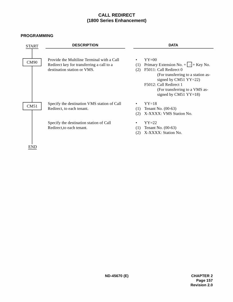
CALL REDIRECT(1800 Series Enhancement)
PROGRAMMING
DESCRIPTION DATA
Provide the Multiline Terminal with a Call Redirect key for transferring a call to a destination station or VMS.
• YY=00(1) Primary Extension No. + + Key No. (2) F5011: Call Redirect 0
(For transferring to a station as-signed by CM51 YY=22)
F5012: Call Redirect 1(For transferring to a VMS as-signed by CM51 YY=18)
Specify the destination VMS station of Call Redirect, to each tenant.
• YY=18(1) Tenant No. (00-63)(2) X-XXXX: VMS Station No.
Specify the destination station of Call Redirect,to each tenant.
• YY=22(1) Tenant No. (00-63)(2) X-XXXX: Station No.
CM90
END
CM51
START
,
ND-45670 (E) CHAPTER 2Page 157
Revision 2.0
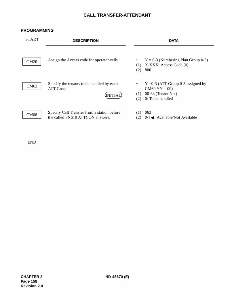
)
CALL TRANSFER-ATTENDANT
PROGRAMMING
DESCRIPTION DATA
Assign the Access code for operator calls. • Y = 0-3 (Numbering Plan Group 0-3(1) X-XXX: Access Code (0) (2) 800
Specify the tenants to be handled by each ATT Group.
• Y =0-3 (ATT Group 0-3 assigned by CM60 YY = 00)
(1) 00-63 (Tenant No.)(2) 0: To be handled
Specify Call Transfer from a station before the called SN610 ATTCON answers.
(1) 063 (2) 0/1 Available/Not Available
CM08
START
END
CM62
CM20
INITIAL
CHAPTER 2 ND-45670 (E)Page 158Revision 2.0
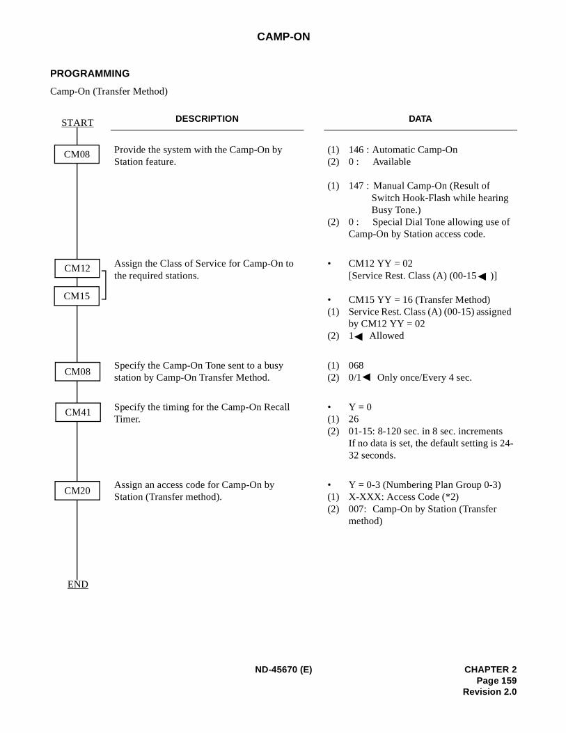
-
CAMP-ON
PROGRAMMING
Camp-On (Transfer Method)
DESCRIPTION DATA
Provide the system with the Camp-On by Station feature.
(1) 146 : Automatic Camp-On(2) 0 : Available
(1) 147 : Manual Camp-On (Result of Switch Hook-Flash while hearing Busy Tone.)
(2) 0 : Special Dial Tone allowing use of Camp-On by Station access code.
Assign the Class of Service for Camp-On to the required stations.
• CM12 YY = 02 [Service Rest. Class (A) (00-15 )]
• CM15 YY = 16 (Transfer Method)(1) Service Rest. Class (A) (00-15) assigned
by CM12 YY = 02(2) 1 Allowed
Specify the Camp-On Tone sent to a busy station by Camp-On Transfer Method.
(1) 068 (2) 0/1 Only once/Every 4 sec.
Specify the timing for the Camp-On Recall Timer.
• Y = 0(1) 26(2) 01-15: 8-120 sec. in 8 sec. increments
If no data is set, the default setting is 2432 seconds.
Assign an access code for Camp-On by Station (Transfer method).
• Y = 0-3 (Numbering Plan Group 0-3)(1) X-XXX: Access Code (*2)(2) 007: Camp-On by Station (Transfer
method)
CM08
START
END
CM08
CM41
CM20
CM12
CM15
ND-45670 (E) CHAPTER 2Page 159
Revision 2.0
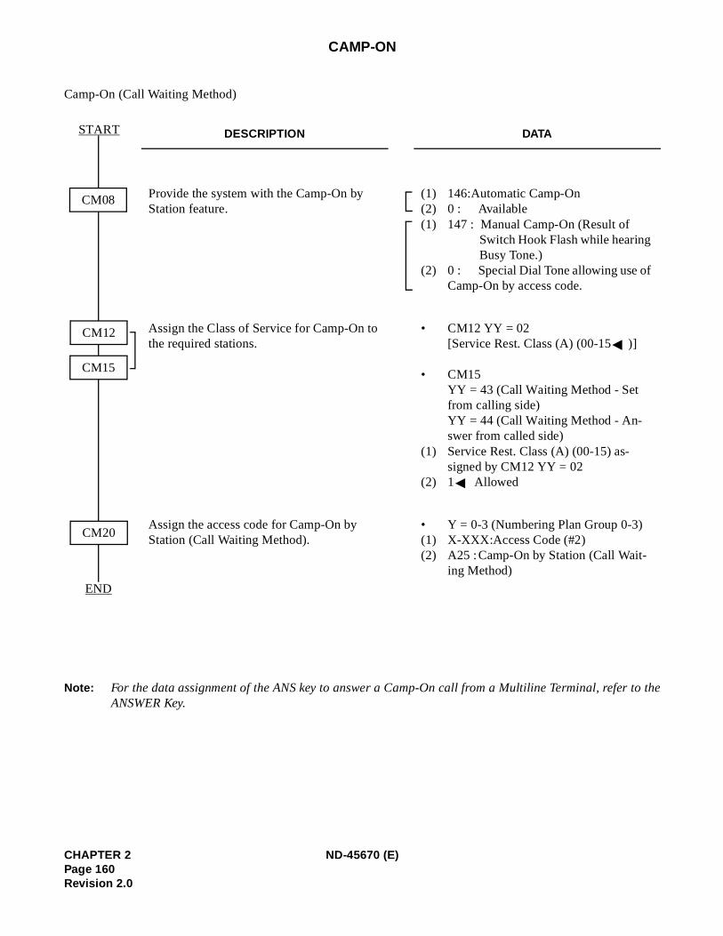
to the
CAMP-ON
Camp-On (Call Waiting Method)
Note: For the data assignment of the ANS key to answer a Camp-On call from a Multiline Terminal, referANSWER Key.
DESCRIPTION DATA
Provide the system with the Camp-On by Station feature.
(1) 146:Automatic Camp-On(2) 0 : Available(1) 147 : Manual Camp-On (Result of
Switch Hook Flash while hearing Busy Tone.)
(2) 0 : Special Dial Tone allowing use of Camp-On by access code.
Assign the Class of Service for Camp-On to the required stations.
• CM12 YY = 02 [Service Rest. Class (A) (00-15 )]
• CM15 YY = 43 (Call Waiting Method - Set from calling side) YY = 44 (Call Waiting Method - An-swer from called side)
(1) Service Rest. Class (A) (00-15) as-signed by CM12 YY = 02
(2) 1 Allowed
Assign the access code for Camp-On by Station (Call Waiting Method).
• Y = 0-3 (Numbering Plan Group 0-3)(1) X-XXX:Access Code (#2)(2) A25 :Camp-On by Station (Call Wait-
ing Method)
CM08
START
END
CM20
CM12
CM15
CHAPTER 2 ND-45670 (E)Page 160Revision 2.0
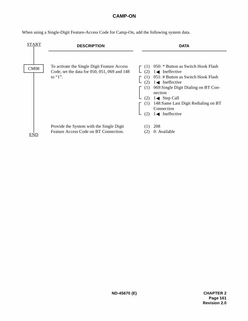
CAMP-ON
When using a Single-Digit Feature-Access Code for Camp-On, add the following system data.
DESCRIPTION DATA
To activate the Single Digit Feature Access Code, set the data for 050, 051, 069 and 148 to “1”.
(1) 050: * Button as Switch Hook Flash(2) 1 Ineffective(1) 051: # Button as Switch Hook Flash(2) 1 Ineffective(1) 069:Single Digit Dialing on BT Con-
nection(2) 1 Step Call(1) 148:Same Last Digit Redialing on BT
Connection (2) 1 Ineffective
Provide the System with the Single Digit Feature Access Code on BT Connection.
(1) 208 (2) 0: Available
CM08
START
END
ND-45670 (E) CHAPTER 2Page 161
Revision 2.0
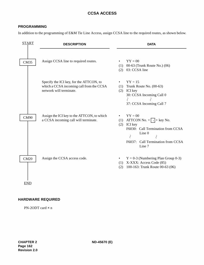
below.
)
CCSA ACCESS
PROGRAMMING
In addition to the programming of E&M Tie Line Access, assign CCSA line to the required routes, as shown
HARDWARE REQUIRED
PN-2ODT card × n
DESCRIPTION DATA
Assign CCSA line to required routes. • YY = 00(1) 00-63 (Trunk Route No.) (06)(2) 03: CCSA line
Specify the ICI key, for the ATTCON, to which a CCSA incoming call from the CCSA network will terminate.
• YY = 15(1) Trunk Route No. (00-63) (2) ICI key
30: CCSA Incoming Call 0
37: CCSA Incoming Call 7
Assign the ICI key to the ATTCON, to which a CCSA incoming call will terminate.
• YY = 00(1) ATTCON No. + + key No.(2) ICI key
F6030: Call Termination from CCSA Line 0
F6037: Call Termination from CCSA Line 7
Assign the CCSA access code. • Y = 0-3 (Numbering Plan Group 0-3(1) X-XXX: Access Code (85)(2) 100-163: Trunk Route 00-63 (06)
CM35
START
END
CM90
CM20
,
CHAPTER 2 ND-45670 (E)Page 162Revision 2.0
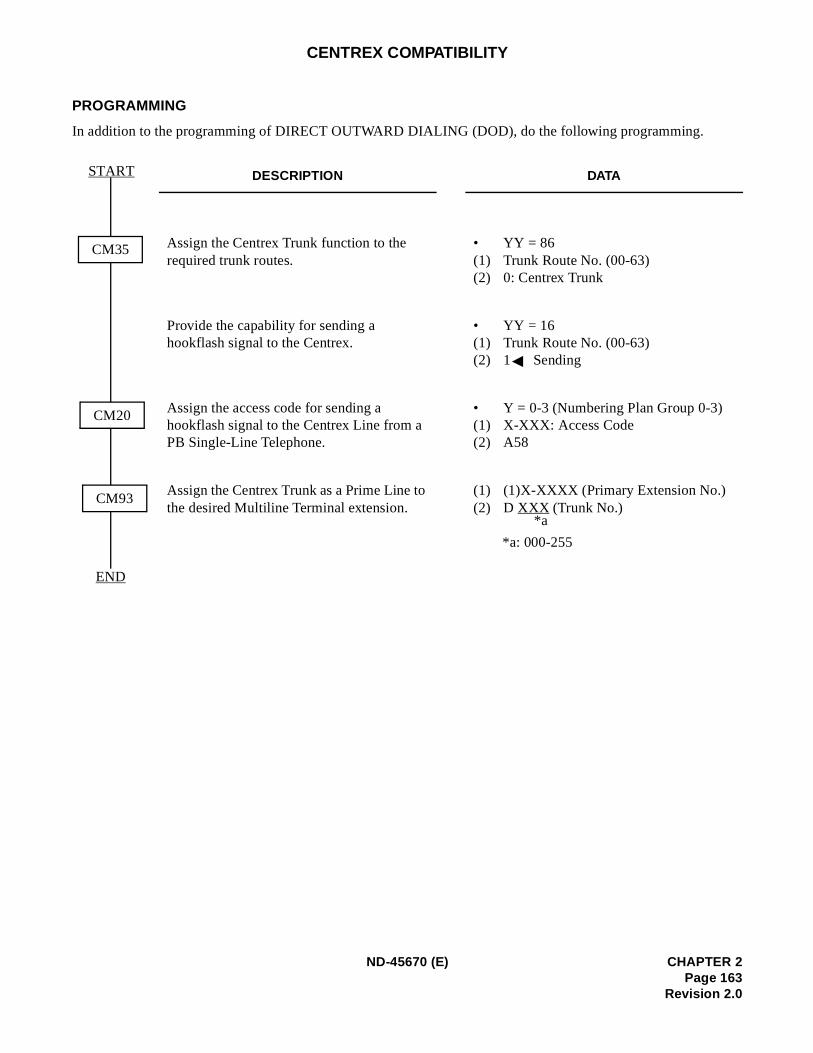
CENTREX COMPATIBILITY
PROGRAMMING
In addition to the programming of DIRECT OUTWARD DIALING (DOD), do the following programming.
DESCRIPTION DATA
Assign the Centrex Trunk function to the required trunk routes.
• YY = 86(1) Trunk Route No. (00-63) (2) 0: Centrex Trunk
Provide the capability for sending a hookflash signal to the Centrex.
• YY = 16(1) Trunk Route No. (00-63) (2) 1 Sending
Assign the access code for sending a hookflash signal to the Centrex Line from a PB Single-Line Telephone.
• Y = 0-3 (Numbering Plan Group 0-3) (1) X-XXX: Access Code(2) A58
Assign the Centrex Trunk as a Prime Line to the desired Multiline Terminal extension.
(1) (1)X-XXXX (Primary Extension No.)(2) D XXX (Trunk No.)
*a: 000-255
CM35
CM93
START
END
CM20
*a
ND-45670 (E) CHAPTER 2Page 163
Revision 2.0
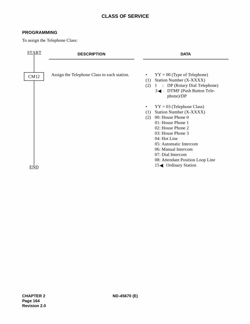
CLASS OF SERVICE
PROGRAMMING
To assign the Telephone Class:
DESCRIPTION DATA
Assign the Telephone Class to each station. • YY = 00 (Type of Telephone)(1) Station Number (X-XXXX) (2) 1 : DP (Rotary Dial Telephone)
3 : DTMF (Push Button Tele-phone)/DP
• YY = 03 (Telephone Class)(1) Station Number (X-XXXX)(2) 00: House Phone 0
01: House Phone 102: House Phone 203: House Phone 304: Hot Line 05: Automatic Intercom 06: Manual Intercom07: Dial Intercom08: Attendant Position Loop Line 15 Ordinary Station
CM12
START
END
CHAPTER 2 ND-45670 (E)Page 164Revision 2.0
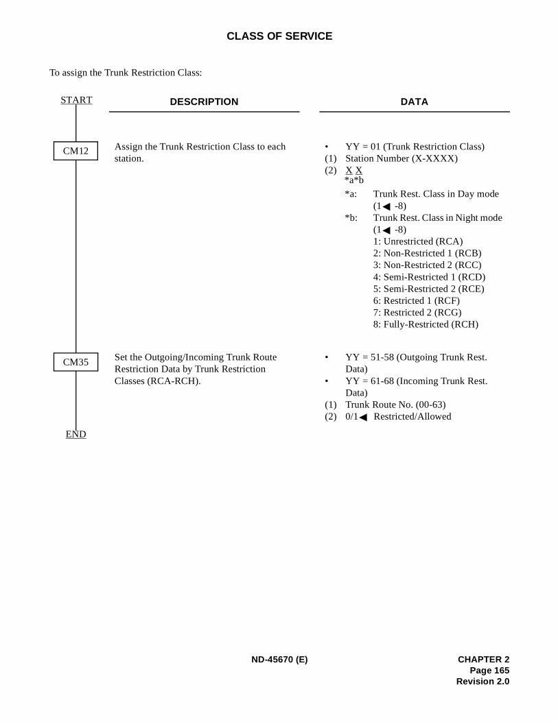
CLASS OF SERVICE
To assign the Trunk Restriction Class:
DESCRIPTION DATA
Assign the Trunk Restriction Class to each station.
• YY = 01 (Trunk Restriction Class)(1) Station Number (X-XXXX) (2) X X
*a: Trunk Rest. Class in Day mode (1 -8)
*b: Trunk Rest. Class in Night mode (1 -8)1: Unrestricted (RCA)2: Non-Restricted 1 (RCB)3: Non-Restricted 2 (RCC)4: Semi-Restricted 1 (RCD) 5: Semi-Restricted 2 (RCE) 6: Restricted 1 (RCF)7: Restricted 2 (RCG)8: Fully-Restricted (RCH)
Set the Outgoing/Incoming Trunk Route Restriction Data by Trunk Restriction Classes (RCA-RCH).
• YY = 51-58 (Outgoing Trunk Rest. Data)
• YY = 61-68 (Incoming Trunk Rest. Data)
(1) Trunk Route No. (00-63)(2) 0/1 Restricted/Allowed
CM12
CM35
START
END
*b*a
ND-45670 (E) CHAPTER 2Page 165
Revision 2.0
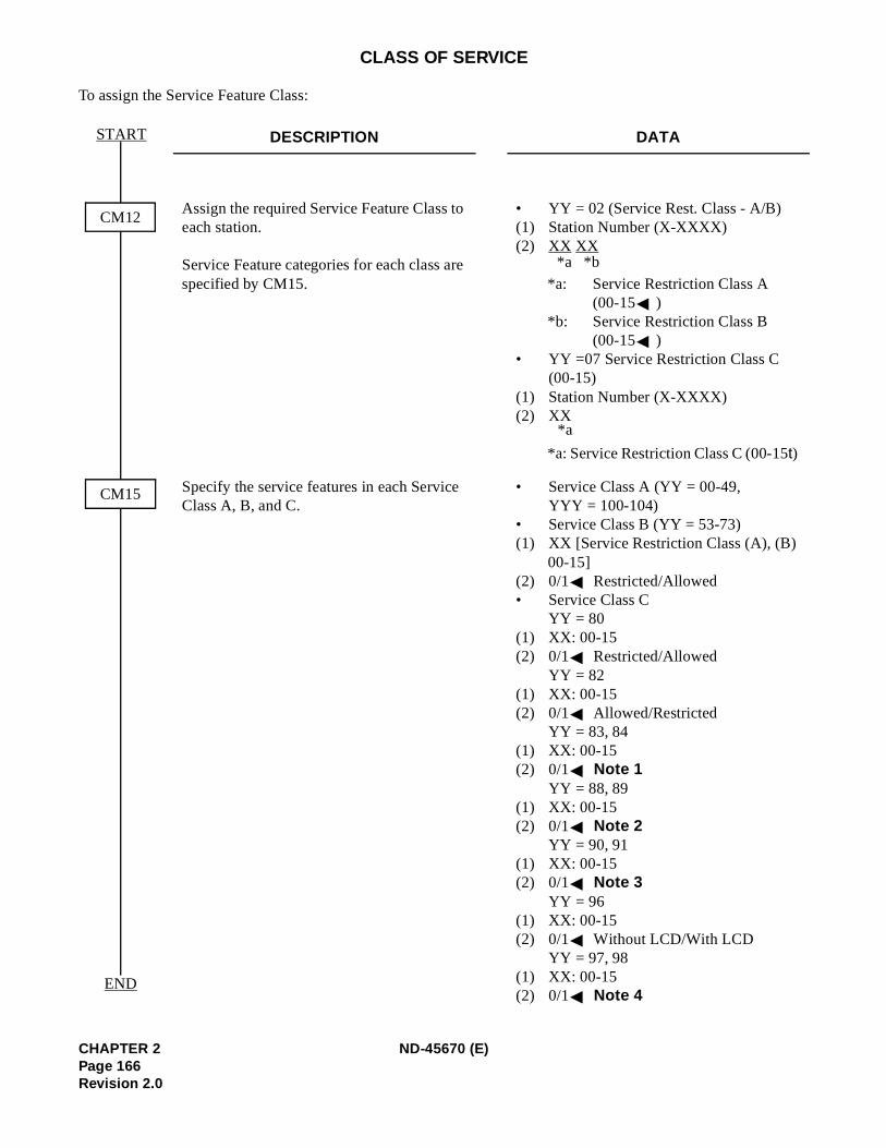
CLASS OF SERVICE
To assign the Service Feature Class:
DESCRIPTION DATA
Assign the required Service Feature Class to each station.
Service Feature categories for each class are specified by CM15.
• YY = 02 (Service Rest. Class - A/B)(1) Station Number (X-XXXX) (2) XX XX
*a: Service Restriction Class A (00-15 )
*b: Service Restriction Class B (00-15 )
• YY =07 Service Restriction Class C (00-15)
(1) Station Number (X-XXXX)(2) XX
*a: Service Restriction Class C (00-15t)
Specify the service features in each Service Class A, B, and C.
• Service Class A (YY = 00-49, YYY = 100-104)
• Service Class B (YY = 53-73) (1) XX [Service Restriction Class (A), (B)
00-15](2) 0/1 Restricted/Allowed• Service Class C
YY = 80 (1) XX: 00-15 (2) 0/1 Restricted/Allowed
YY = 82 (1) XX: 00-15 (2) 0/1 Allowed/Restricted
YY = 83, 84 (1) XX: 00-15 (2) 0/1 Note 1
YY = 88, 89 (1) XX: 00-15 (2) 0/1 Note 2
YY = 90, 91 (1) XX: 00-15 (2) 0/1 Note 3
YY = 96 (1) XX: 00-15 (2) 0/1 Without LCD/With LCD
YY = 97, 98 (1) XX: 00-15 (2) 0/1 Note 4
CM12
CM15
START
END
*b*a
*a
CHAPTER 2 ND-45670 (E)Page 166Revision 2.0
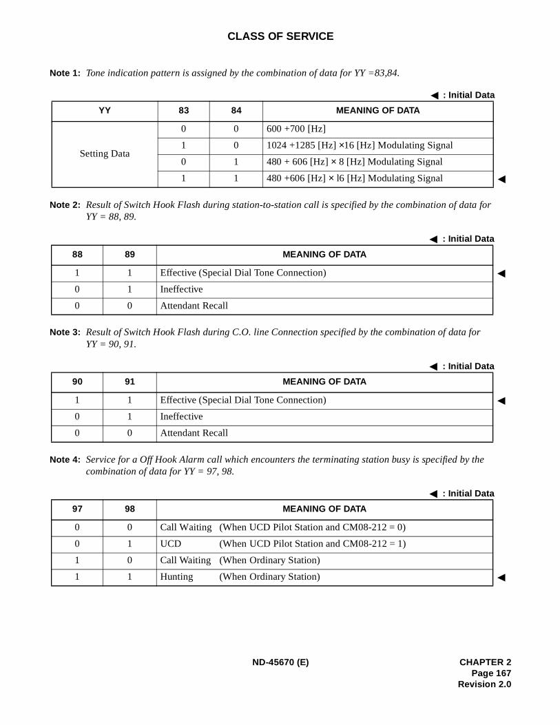
r
CLASS OF SERVICE
Note 1: Tone indication pattern is assigned by the combination of data for YY =83,84.
Note 2: Result of Switch Hook Flash during station-to-station call is specified by the combination of data foYY = 88, 89.
Note 3: Result of Switch Hook Flash during C.O. line Connection specified by the combination of data for YY = 90, 91.
Note 4: Service for a Off Hook Alarm call which encounters the terminating station busy is specified by thecombination of data for YY = 97, 98.
: Initial Data
YY 83 84 MEANING OF DATA
Setting Data
0 0 600 +700 [Hz]
1 0 1024 +1285 [Hz] ×16 [Hz] Modulating Signal
0 1 480 + 606 [Hz] × 8 [Hz] Modulating Signal
1 1 480 +606 [Hz] × l6 [Hz] Modulating Signal
: Initial Data
88 89 MEANING OF DATA
1 1 Effective (Special Dial Tone Connection)
0 1 Ineffective
0 0 Attendant Recall
: Initial Data
90 91 MEANING OF DATA
1 1 Effective (Special Dial Tone Connection)
0 1 Ineffective
0 0 Attendant Recall
: Initial Data
97 98 MEANING OF DATA
0 0 Call Waiting (When UCD Pilot Station and CM08-212 = 0)
0 1 UCD (When UCD Pilot Station and CM08-212 = 1)
1 0 Call Waiting (When Ordinary Station)
1 1 Hunting (When Ordinary Station)
ND-45670 (E) CHAPTER 2Page 167
Revision 2.0
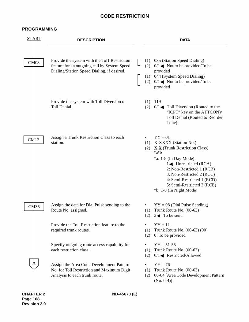
CODE RESTRICTION
PROGRAMMING
DESCRIPTION DATA
Provide the system with the Tol1 Restriction feature for an outgoing call by System Speed Dialing/Station Speed Dialing, if desired.
(1) 035 (Station Speed Dialing) (2) 0/1 Not to be provided/To be
provided(1) 044 (System Speed Dialing)(2) 0/1 Not to be provided/To be
provided
Provide the system with Toll Diversion or Toll Denial.
(1) 119 (2) 0/1 Toll Diversion (Routed to the
“ICPT” key on the ATTCON)/Toll Denial (Routed to Reorder Tone)
Assign a Trunk Restriction Class to each station.
• YY = 01(1) X-XXXX (Station No.)(2) X X (Trunk Restriction Class)
*a: 1-8 (In Day Mode) 1 Unrestricted (RCA) 2: Non-Restricted 1 (RCB) 3: Non-Restricted 2 (RCC) 4: Semi-Restricted 1 (RCD)5: Semi-Restricted 2 (RCE)
*b: 1-8 (In Night Mode)
Assign the data for Dial Pulse sending to the Route No. assigned.
• YY = 08 (Dial Pulse Sending) (1) Trunk Route No. (00-63)(2) 3 To be sent.
Provide the Toll Restriction feature to the required trunk routes.
• YY = 11(1) Trunk Route No. (00-63) (00)(2) 0: To be provided
Specify outgoing route access capability for each restriction class.
• YY = 51-55 (1) Trunk Route No. (00-63) (2) 0/1 Restricted/Allowed
Assign the Area Code Development Pattern No. for Toll Restriction and Maximum Digit Analysis to each trunk route.
• YY = 76(1) Trunk Route No. (00-63) (2) 00-04 [Area Code Development Pattern
(No. 0-4)]
CM08
CM12
START
CM35
A
*b*a
CHAPTER 2 ND-45670 (E)Page 168Revision 2.0
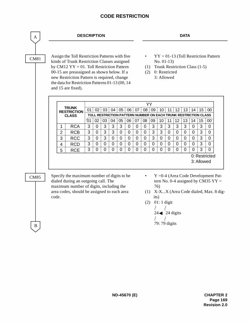
CODE RESTRICTION
DESCRIPTION DATA
Assign the Toll Restriction Patterns with five kinds of Trunk Restriction Classes assigned by CM12 YY = 01. Toll Restriction Pattern 00-15 are preassigned as shown below. If a new Restriction Pattern is required, change the data for Restriction Patterns 01-13 (00, 14 and 15 are fixed).
• YY = 01-13 (Toll Restriction Pattern No. 01-13)
(1) Trunk Restriction Class (1-5) (2) 0: Restricted
3: Allowed
Specify the maximum number of digits to be dialed during an outgoing call. The maximum number of digits, including the area codes, should be assigned to each area code.
• Y =0-4 (Area Code Development Pat-tern No. 0-4 assigned by CM35 YY = 76)
(1) X-X...X (Area Code dialed, Max. 8 dig-its)
(2) 01: 1 digit
24 24 digits
79: 79 digits
CM81
B
A
CM85
YYTRUNK
RESTRICTIONCLASS
01 02 03 04 05 06 07 08 09 10 11 12 13 14 15 00
01 02 03 04 05 06 07 08 09 10 11 12 13 14 15 00TOLL RESTRICTION PATTERN NUMBER ON EACH TRUNK RESTRICTION CLASS
12345
RCARCBRCCRCDRCE
33333
00000
33300
33000
30000
00000
00000
00000
33300
33000
30000
30000
30000
00000
33333
00000
0:3:
RestrictedAllowed
ND-45670 (E) CHAPTER 2Page 169
Revision 2.0
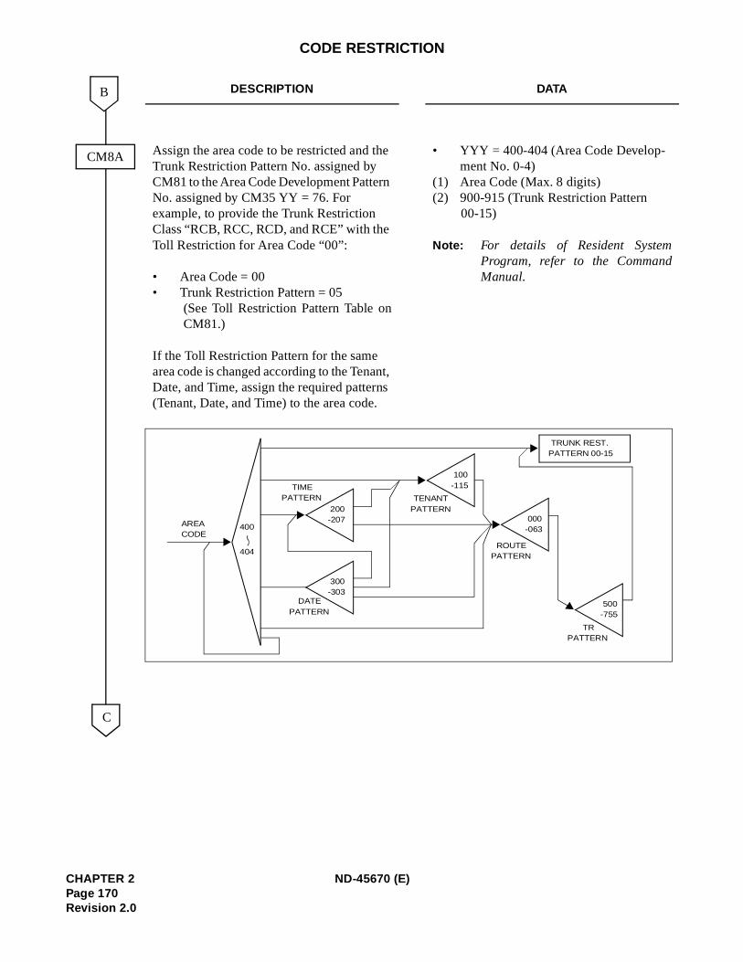
CODE RESTRICTION
DESCRIPTION DATA
Assign the area code to be restricted and the Trunk Restriction Pattern No. assigned by CM81 to the Area Code Development Pattern No. assigned by CM35 YY = 76. For example, to provide the Trunk Restriction Class “RCB, RCC, RCD, and RCE” with the Toll Restriction for Area Code “00”:
• Area Code = 00 • Trunk Restriction Pattern = 05
(See Toll Restriction Pattern Table onCM81.)
If the Toll Restriction Pattern for the same area code is changed according to the Tenant, Date, and Time, assign the required patterns (Tenant, Date, and Time) to the area code.
• YYY = 400-404 (Area Code Develop-ment No. 0-4)
(1) Area Code (Max. 8 digits) (2) 900-915 (Trunk Restriction Pattern
00-15)
Note: For details of Resident SystemProgram, refer to the CommandManual.
CM8A
C
B
AREACODE
400
404
DATEPATTERN
200-207
300-303
100-115
TENANTPATTERN
TIMEPATTERN
000-063
ROUTEPATTERN
500-755
TRPATTERN
TRUNK REST. PATTERN 00-15
CHAPTER 2 ND-45670 (E)Page 170Revision 2.0
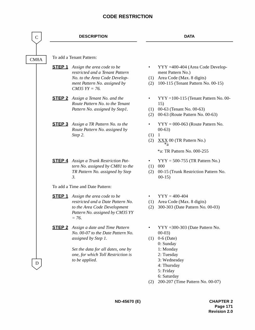
CODE RESTRICTION
DESCRIPTION DATA
To add a Tenant Pattern:
STEP 1 Assign the area code to be restricted and a Tenant Pattern No. to the Area Code Develop-ment Pattern No. assigned by CM35 YY = 76.
• YYY =400-404 (Area Code Develop-ment Pattern No.)
(1) Area Code (Max. 8 digits)(2) 100-115 (Tenant Pattern No. 00-15)
STEP 2 Assign a Tenant No. and the Route Pattern No. to the Tenant Pattern No. assigned by Step1.
• YYY =100-115 (Tenant Pattern No. 00-15)
(1) 00-63 (Tenant No. 00-63) (2) 00-63 (Route Pattern No. 00-63)
STEP 3 Assign a TR Pattern No. to the Route Pattern No. assigned by Step 2.
• YYY = 000-063 (Route Pattern No. 00-63)
(1) 1 (2) XXX 00 (TR Pattern No.)
*a: TR Pattern No. 000-255
STEP 4 Assign a Trunk Restriction Pat-tern No. assigned by CM81 to the TR Pattern No. assigned by Step 3.
• YYY = 500-755 (TR Pattern No.) (1) 000 (2) 00-15 (Trunk Restriction Pattern No.
00-15)
To add a Time and Date Pattern:
STEP 1 Assign the area code to be restricted and a Date Pattern No. to the Area Code Development Pattern No. assigned by CM35 YY = 76.
• YYY = 400-404(1) Area Code (Max. 8 digits)(2) 300-303 (Date Pattern No. 00-03)
STEP 2 Assign a date and Time Pattern No. 00-07 to the Date Pattern No. assigned by Step 1.
Set the data for all dates, one by one, for which Toll Restriction is to be applied.
• YYY =300-303 (Date Pattern No. 00-03)
(1) 0-6 (Date)0: Sunday 1: Monday 2: Tuesday 3: Wednesday 4: Thursday 5: Friday 6: Saturday
(2) 200-207 (Time Pattern No. 00-07)
CM8A
D
C
*a
ND-45670 (E) CHAPTER 2Page 171
Revision 2.0
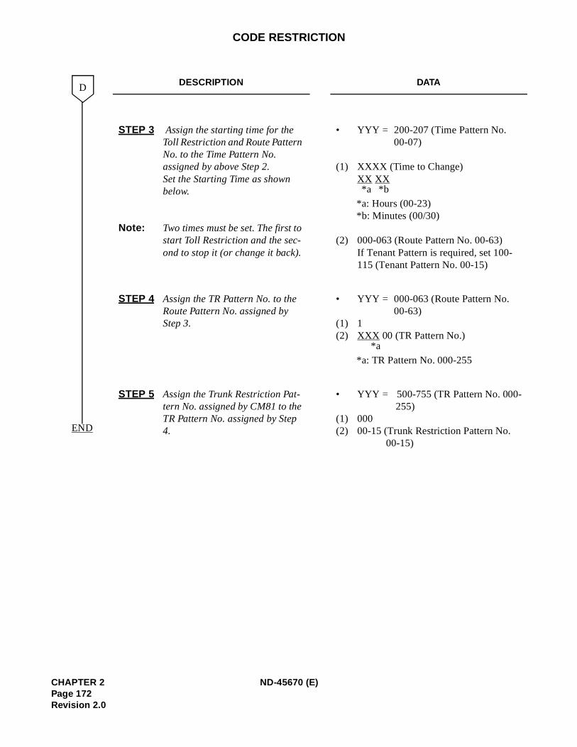
CODE RESTRICTION
DESCRIPTION DATA
STEP 3 Assign the starting time for the Toll Restriction and Route Pattern No. to the Time Pattern No. assigned by above Step 2. Set the Starting Time as shown below.
Note: Two times must be set. The first to start Toll Restriction and the sec-ond to stop it (or change it back).
• YYY = 200-207 (Time Pattern No. 00-07)
(1) XXXX (Time to Change) XX XX
*a: Hours (00-23) *b: Minutes (00/30)
(2) 000-063 (Route Pattern No. 00-63)If Tenant Pattern is required, set 100-115 (Tenant Pattern No. 00-15)
STEP 4 Assign the TR Pattern No. to the Route Pattern No. assigned by Step 3.
• YYY = 000-063 (Route Pattern No. 00-63)
(1) 1 (2) XXX 00 (TR Pattern No.)
*a: TR Pattern No. 000-255
STEP 5 Assign the Trunk Restriction Pat-tern No. assigned by CM81 to the TR Pattern No. assigned by Step 4.
• YYY = 500-755 (TR Pattern No. 000-255)
(1) 000 (2) 00-15 (Trunk Restriction Pattern No.
00-15)
D
END
*a *b
*a
CHAPTER 2 ND-45670 (E)Page 172Revision 2.0
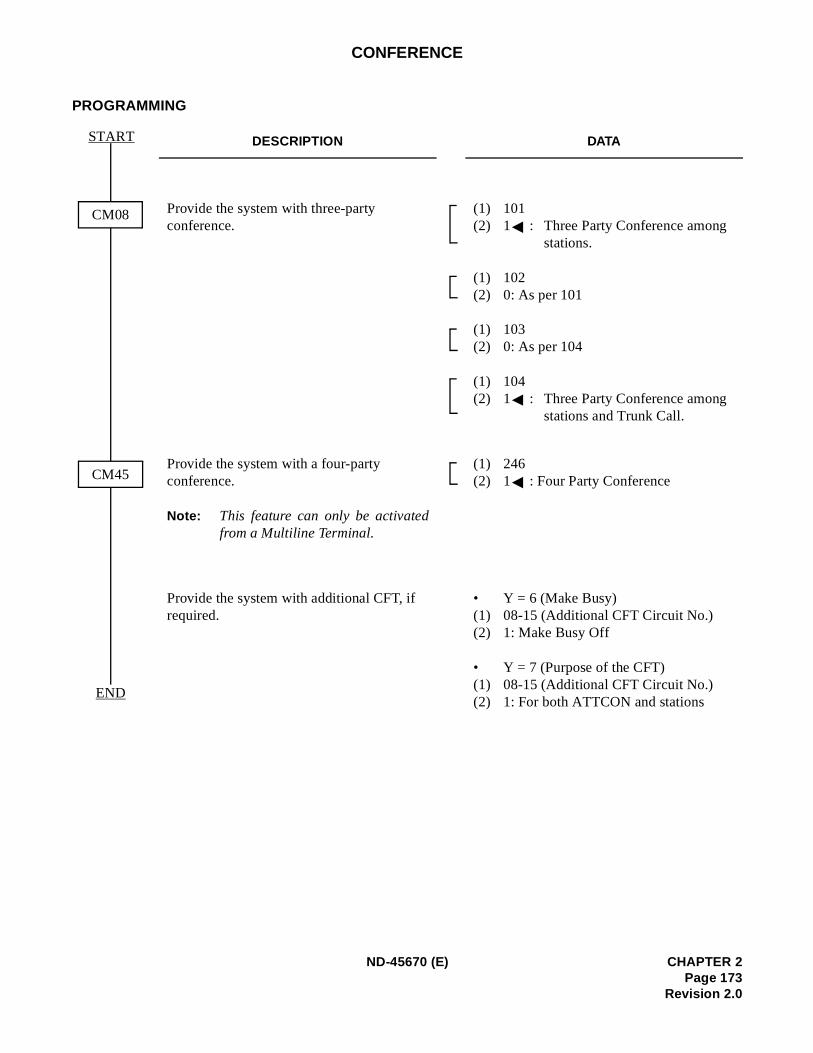
CONFERENCE
PROGRAMMING
DESCRIPTION DATA
Provide the system with three-party conference.
(1) 101 (2) 1 : Three Party Conference among
stations.
(1) 102 (2) 0: As per 101
(1) 103 (2) 0: As per 104
(1) 104 (2) 1 : Three Party Conference among
stations and Trunk Call.
Provide the system with a four-party conference.
Note: This feature can only be activatedfrom a Multiline Terminal.
(1) 246 (2) 1 : Four Party Conference
Provide the system with additional CFT, if required.
• Y = 6 (Make Busy)(1) 08-15 (Additional CFT Circuit No.)(2) 1: Make Busy Off
• Y = 7 (Purpose of the CFT) (1) 08-15 (Additional CFT Circuit No.)(2) 1: For both ATTCON and stations
CM08
CM45
START
END
ND-45670 (E) CHAPTER 2Page 173
Revision 2.0
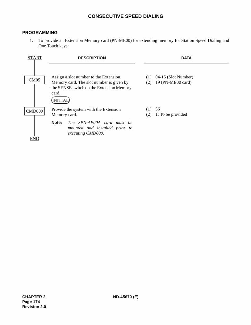
g and
CONSECUTIVE SPEED DIALING
PROGRAMMING
1. To provide an Extension Memory card (PN-ME00) for extending memory for Station Speed DialinOne Touch keys:
DESCRIPTION DATA
Assign a slot number to the Extension Memory card. The slot number is given by the SENSE switch on the Extension Memory card.
Provide the system with the Extension Memory card.
(1) 04-15 (Slot Number)(2) 19 (PN-ME00 card)
(1) 56(2) 1: To be provided
Note: The SPN-AP00A card must bemounted and installed prior toexecuting CMD000.
CM05
CMD000
START
END
INITIAL
CHAPTER 2 ND-45670 (E)Page 174Revision 2.0
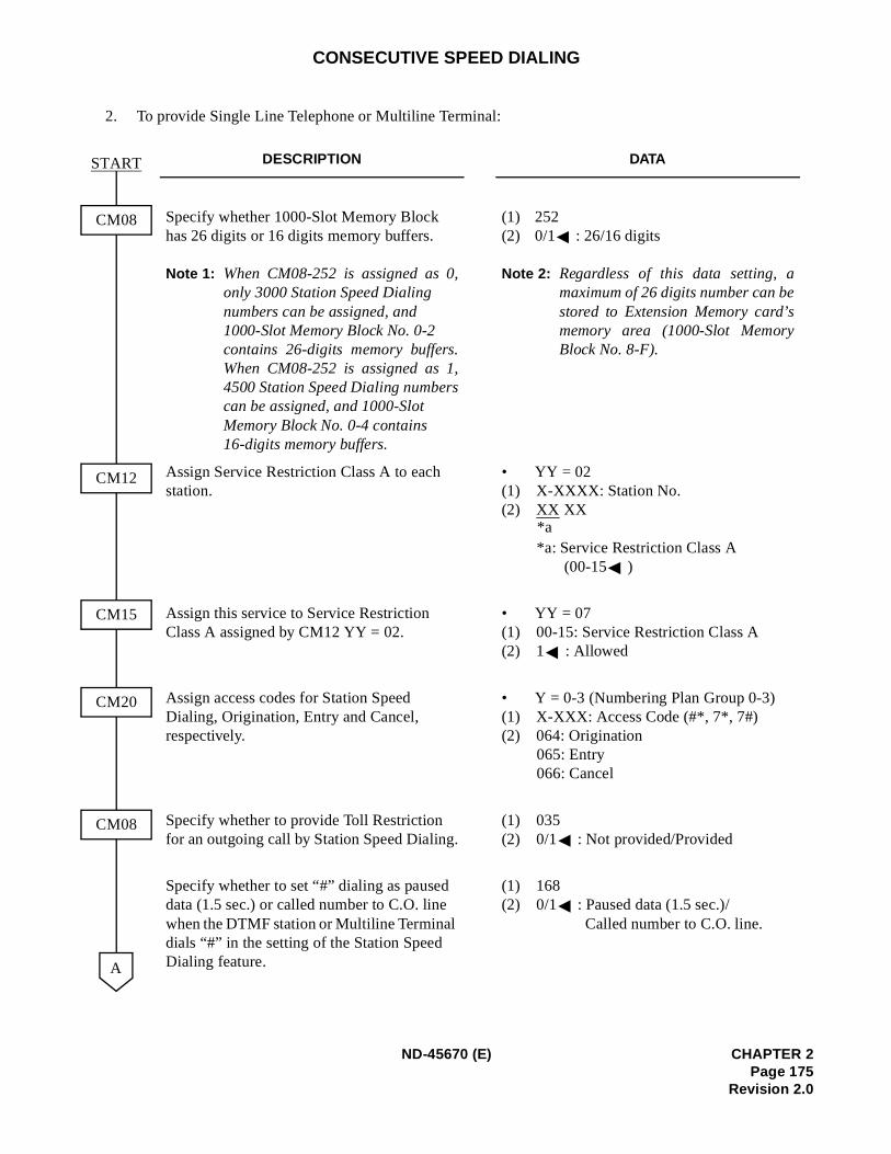
CONSECUTIVE SPEED DIALING
2. To provide Single Line Telephone or Multiline Terminal:
DESCRIPTION DATA
Specify whether 1000-Slot Memory Block has 26 digits or 16 digits memory buffers.
Note 1: When CM08-252 is assigned as 0,only 3000 Station Speed Dialing numbers can be assigned, and 1000-Slot Memory Block No. 0-2 contains 26-digits memory buffers.When CM08-252 is assigned as 1,4500 Station Speed Dialing numberscan be assigned, and 1000-Slot Memory Block No. 0-4 contains 16-digits memory buffers.
(1) 252(2) 0/1 : 26/16 digits
Note 2: Regardless of this data setting, amaximum of 26 digits number can bestored to Extension Memory card’smemory area (1000-Slot MemoryBlock No. 8-F).
Assign Service Restriction Class A to each station.
• YY = 02(1) X-XXXX: Station No.(2) XX XX
*a: Service Restriction Class A (00-15 )
Assign this service to Service Restriction Class A assigned by CM12 YY = 02.
• YY = 07(1) 00-15: Service Restriction Class A(2) 1 : Allowed
Assign access codes for Station Speed Dialing, Origination, Entry and Cancel, respectively.
• Y = 0-3 (Numbering Plan Group 0-3)(1) X-XXX: Access Code (#*, 7*, 7#)(2) 064: Origination
065: Entry 066: Cancel
Specify whether to provide Toll Restriction for an outgoing call by Station Speed Dialing.
(1) 035(2) 0/1 : Not provided/Provided
Specify whether to set “#” dialing as paused data (1.5 sec.) or called number to C.O. line when the DTMF station or Multiline Terminal dials “#” in the setting of the Station Speed Dialing feature.
(1) 168(2) 0/1 : Paused data (1.5 sec.)/
Called number to C.O. line.
CM08
A
CM12
CM15
CM20
CM08
START
*a
ND-45670 (E) CHAPTER 2Page 175
Revision 2.0
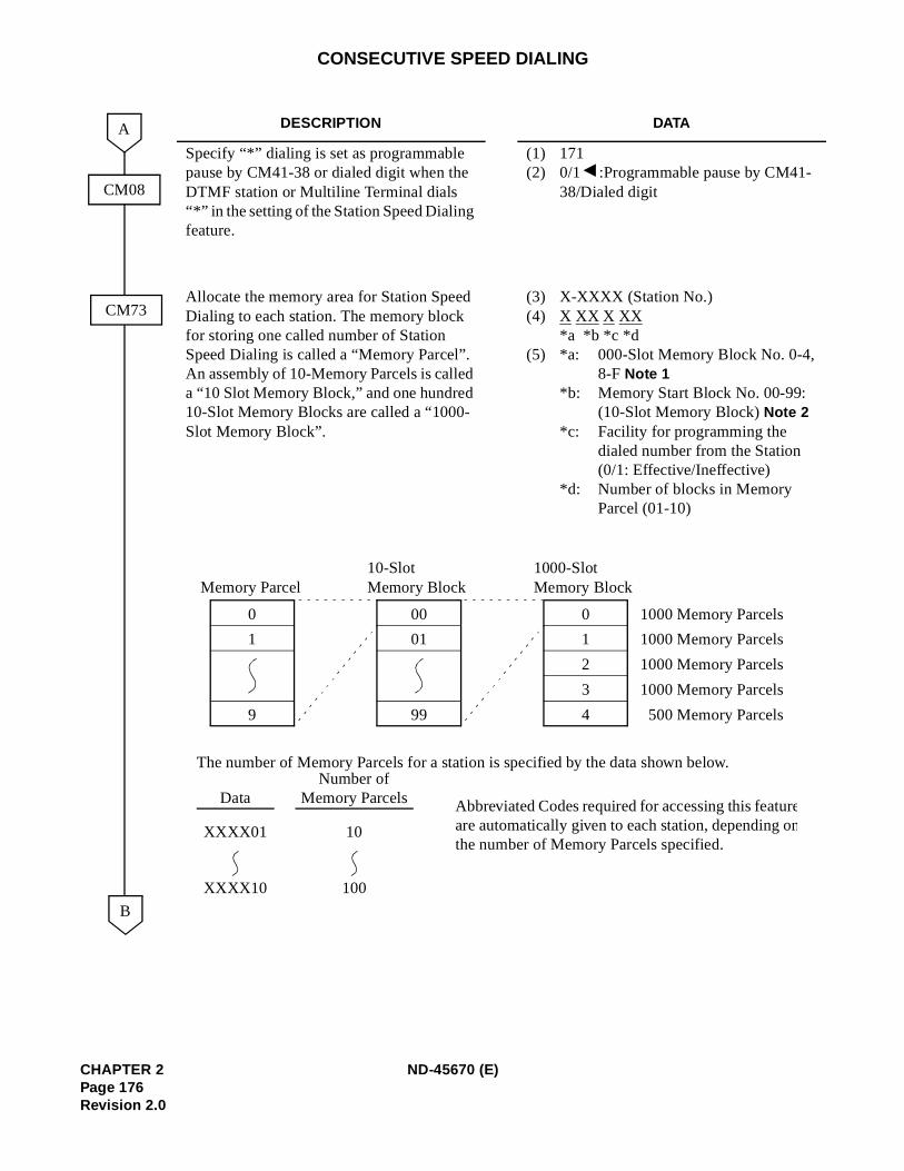
CONSECUTIVE SPEED DIALING
DESCRIPTION DATA
Specify “*” dialing is set as programmable pause by CM41-38 or dialed digit when the DTMF station or Multiline Terminal dials “*” in the setting of the Station Speed Dialing feature.
(1) 171(2) 0/1 :Programmable pause by CM41-
38/Dialed digit
Allocate the memory area for Station Speed Dialing to each station. The memory block for storing one called number of Station Speed Dialing is called a “Memory Parcel”. An assembly of 10-Memory Parcels is called a “10 Slot Memory Block,” and one hundred 10-Slot Memory Blocks are called a “1000-Slot Memory Block”.
(3) X-XXXX (Station No.)(4) X XX X XX
*a *b *c *d (5) *a: 000-Slot Memory Block No. 0-4,
8-F Note 1 *b: Memory Start Block No. 00-99:
(10-Slot Memory Block) Note 2 *c: Facility for programming the
dialed number from the Station(0/1: Effective/Ineffective)
*d: Number of blocks in Memory Parcel (01-10)
CM08
CM73
B
A
The number of Memory Parcels for a station is specified by the data shown below.
DataNumber of
Memory Parcels Abbreviated Codes required for accessing this featureare automatically given to each station, depending onthe number of Memory Parcels specified.
XXXX01 10
XXXX10 100
0
4
1
2
3
1000-SlotMemory Block
0
9
1
Memory Parcel
00
99
01
10-SlotMemory Block
1000 Memory Parcels
1000 Memory Parcels
1000 Memory Parcels
1000 Memory Parcels
500 Memory Parcels
CHAPTER 2 ND-45670 (E)Page 176Revision 2.0
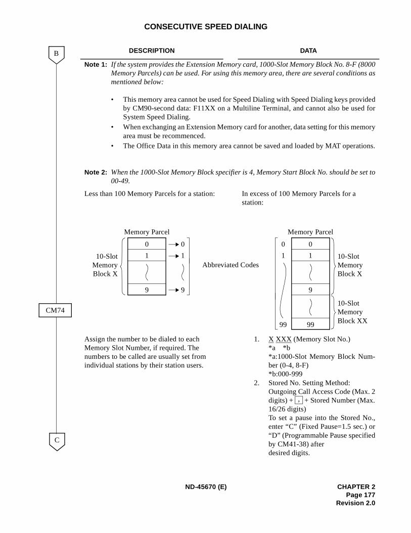
(8000ns as
videdd for
mory
tions.
set to
.,r
CONSECUTIVE SPEED DIALING
DESCRIPTION DATA
Note 1: If the system provides the Extension Memory card, 1000-Slot Memory Block No. 8-F Memory Parcels) can be used. For using this memory area, there are several conditiomentioned below:
• This memory area cannot be used for Speed Dialing with Speed Dialing keys proby CM90-second data: F11XX on a Multiline Terminal, and cannot also be useSystem Speed Dialing.
• When exchanging an Extension Memory card for another, data setting for this mearea must be recommenced.
• The Office Data in this memory area cannot be saved and loaded by MAT opera
Note 2: When the 1000-Slot Memory Block specifier is 4, Memory Start Block No. should be00-49.
Less than 100 Memory Parcels for a station: In excess of 100 Memory Parcels for a station:
Assign the number to be dialed to each Memory Slot Number, if required. The numbers to be called are usually set from individual stations by their station users.
1. X XXX (Memory Slot No.) *a *b *a:1000-Slot Memory Block Num-ber (0-4, 8-F) *b:000-999
2. Stored No. Setting Method: Outgoing Call Access Code (Max. 2digits) + + Stored Number (Max.16/26 digits)To set a pause into the Stored Noenter “C” (Fixed Pause=1.5 sec.) o“D” (Programmable Pause specifiedby CM41-38) after desired digits.
C
B
CM74
0
9
1
Memory Parcel
10-SlotMemoryBlock X
Memory Parcel
0
9
1
0
9
1 10-Slot Memory Block X
99
10-Slot Memory Block XX
0
1
99
Abbreviated Codes
,
ND-45670 (E) CHAPTER 2Page 177
Revision 2.0
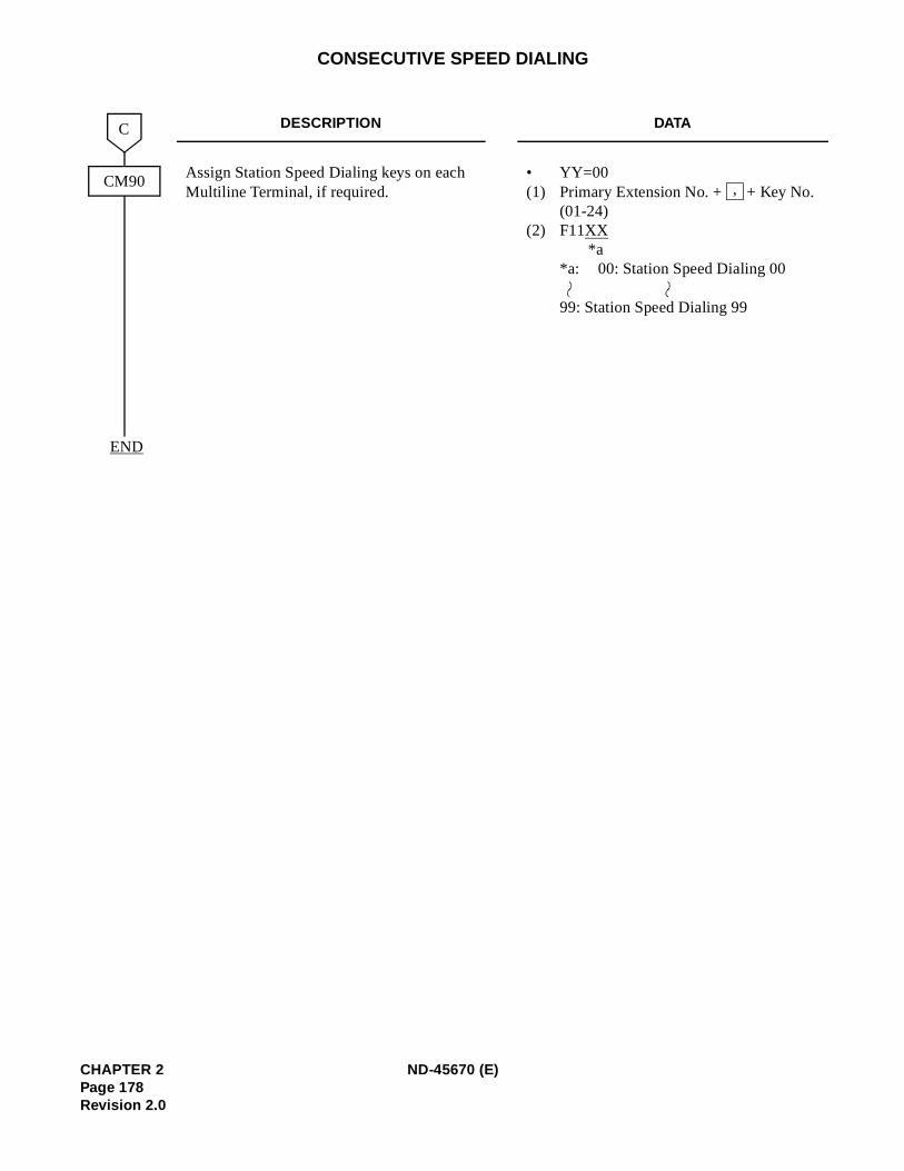
CONSECUTIVE SPEED DIALING
DESCRIPTION DATA
Assign Station Speed Dialing keys on each Multiline Terminal, if required.
• YY=00(1) Primary Extension No. + + Key No.
(01-24)(2) F11XX
*a *a: 00: Station Speed Dialing 00
99: Station Speed Dialing 99
CM90
C
END
,
CHAPTER 2 ND-45670 (E)Page 178Revision 2.0
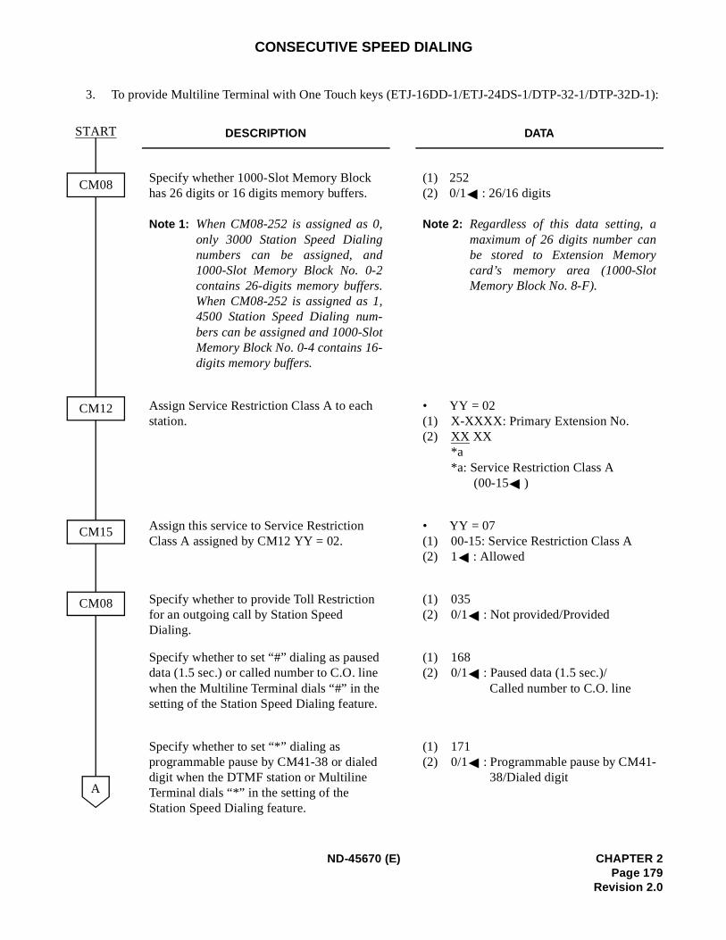
-1):
CONSECUTIVE SPEED DIALING
3. To provide Multiline Terminal with One Touch keys (ETJ-16DD-1/ETJ-24DS-1/DTP-32-1/DTP-32D
DESCRIPTION DATA
Specify whether 1000-Slot Memory Block has 26 digits or 16 digits memory buffers.
Note 1: When CM08-252 is assigned as 0,only 3000 Station Speed Dialingnumbers can be assigned, and1000-Slot Memory Block No. 0-2contains 26-digits memory buffers.When CM08-252 is assigned as 1,4500 Station Speed Dialing num-bers can be assigned and 1000-SlotMemory Block No. 0-4 contains 16-digits memory buffers.
(1) 252(2) 0/1 : 26/16 digits
Note 2: Regardless of this data setting, amaximum of 26 digits number canbe stored to Extension Memorycard’s memory area (1000-SlotMemory Block No. 8-F).
Assign Service Restriction Class A to each station.
• YY = 02 (1) X-XXXX: Primary Extension No.(2) XX XX
*a*a: Service Restriction Class A
(00-15 )
Assign this service to Service Restriction Class A assigned by CM12 YY = 02.
• YY = 07(1) 00-15: Service Restriction Class A(2) 1 : Allowed
Specify whether to provide Toll Restriction for an outgoing call by Station Speed Dialing.
(1) 035(2) 0/1 : Not provided/Provided
Specify whether to set “#” dialing as paused data (1.5 sec.) or called number to C.O. line when the Multiline Terminal dials “#” in the setting of the Station Speed Dialing feature.
(1) 168(2) 0/1 : Paused data (1.5 sec.)/
Called number to C.O. line
Specify whether to set “*” dialing as programmable pause by CM41-38 or dialed digit when the DTMF station or Multiline Terminal dials “*” in the setting of the Station Speed Dialing feature.
(1) 171(2) 0/1 : Programmable pause by CM41-
38/Dialed digit
START
CM08
A
CM12
CM15
CM08
ND-45670 (E) CHAPTER 2Page 179
Revision 2.0
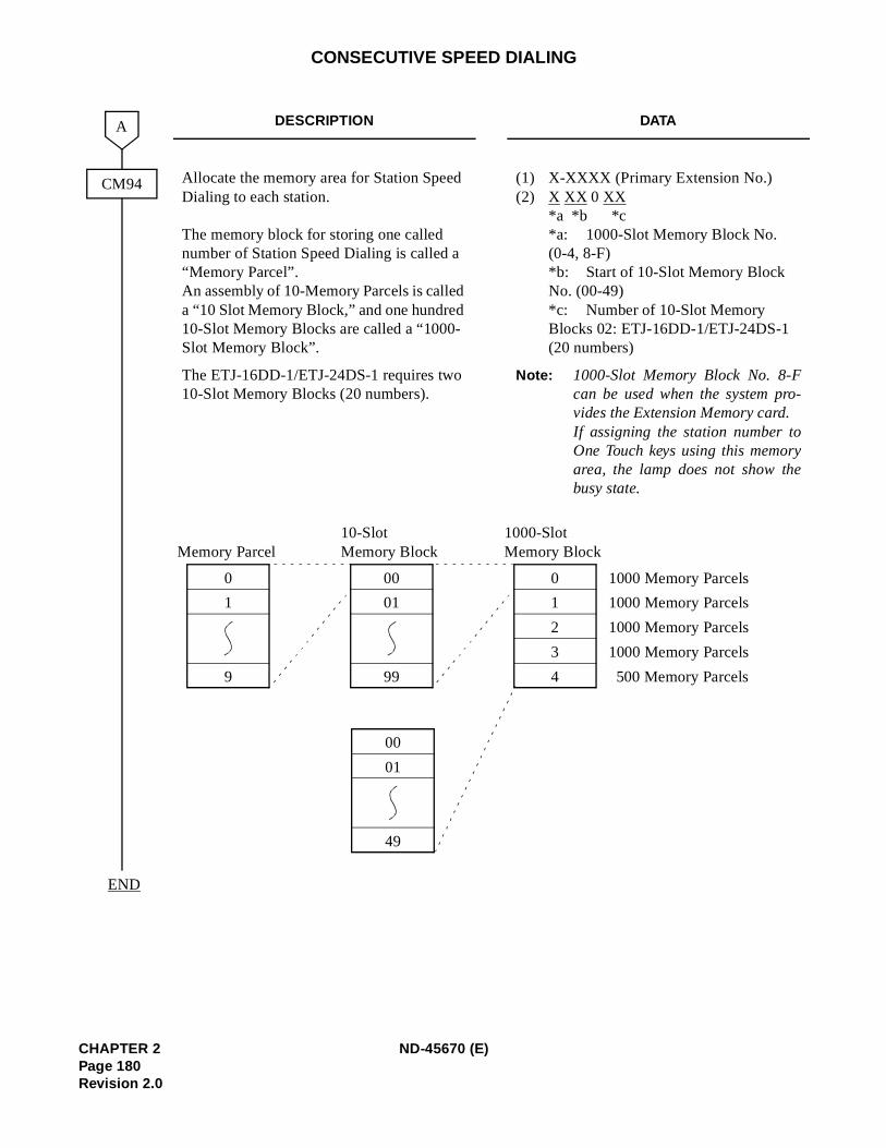
-
CONSECUTIVE SPEED DIALING
DESCRIPTION DATA
Allocate the memory area for Station Speed Dialing to each station.
The memory block for storing one called number of Station Speed Dialing is called a “Memory Parcel”. An assembly of 10-Memory Parcels is called a “10 Slot Memory Block,” and one hundred 10-Slot Memory Blocks are called a “1000-Slot Memory Block”.
(1) X-XXXX (Primary Extension No.)(2) X XX 0 XX
*a *b *c *a: 1000-Slot Memory Block No. (0-4, 8-F) *b: Start of 10-Slot Memory Block No. (00-49) *c: Number of 10-Slot Memory Blocks 02: ETJ-16DD-1/ETJ-24DS-1 (20 numbers)
The ETJ-16DD-1/ETJ-24DS-1 requires two 10-Slot Memory Blocks (20 numbers).
Note: 1000-Slot Memory Block No. 8-Fcan be used when the system provides the Extension Memory card.If assigning the station number toOne Touch keys using this memoryarea, the lamp does not show thebusy state.
CM94
A
END
0
4
1
2
3
1000-SlotMemory Block
0
9
1
Memory Parcel
00
99
01
10-SlotMemory Block
1000 Memory Parcels
1000 Memory Parcels
1000 Memory Parcels
1000 Memory Parcels
500 Memory Parcels
00
49
01
CHAPTER 2 ND-45670 (E)Page 180Revision 2.0
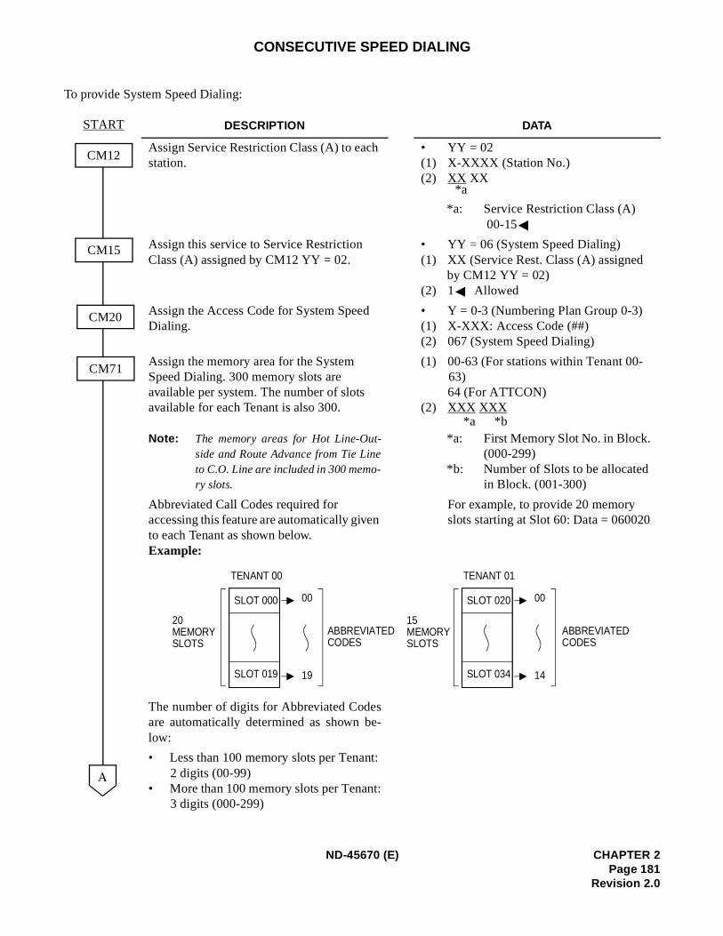
CONSECUTIVE SPEED DIALING
To provide System Speed Dialing:
DESCRIPTION DATA
Assign Service Restriction Class (A) to each station.
• YY = 02(1) X-XXXX (Station No.)(2) XX XX
*a: Service Restriction Class (A) 00-15
Assign this service to Service Restriction Class (A) assigned by CM12 YY = 02.
• YY = 06 (System Speed Dialing)(1) XX (Service Rest. Class (A) assigned
by CM12 YY = 02) (2) 1 Allowed
Assign the Access Code for System Speed Dialing.
• Y = 0-3 (Numbering Plan Group 0-3)(1) X-XXX: Access Code (##) (2) 067 (System Speed Dialing)
Assign the memory area for the System Speed Dialing. 300 memory slots are available per system. The number of slots available for each Tenant is also 300.
Note: The memory areas for Hot Line-Out-side and Route Advance from Tie Lineto C.O. Line are included in 300 memo-ry slots.
(1) 00-63 (For stations within Tenant 00-63)64 (For ATTCON)
(2) XXX XXX
*a: First Memory Slot No. in Block. (000-299)
*b: Number of Slots to be allocated in Block. (001-300)
Abbreviated Call Codes required for accessing this feature are automatically given to each Tenant as shown below. Example:
The number of digits for Abbreviated Codesare automatically determined as shown be-low:
For example, to provide 20 memory slots starting at Slot 60: Data = 060020
• Less than 100 memory slots per Tenant:2 digits (00-99)
• More than 100 memory slots per Tenant:3 digits (000-299)
CM12
CM20
CM71
START
A
CM15
*a
*a *b
TENANT 00
SLOT 000
SLOT 019
20MEMORYSLOTS
00
19
ABBREVIATEDCODES
TENANT 01
SLOT 020
SLOT 034
15MEMORYSLOTS
00
14
ABBREVIATEDCODES
ND-45670 (E) CHAPTER 2Page 181
Revision 2.0
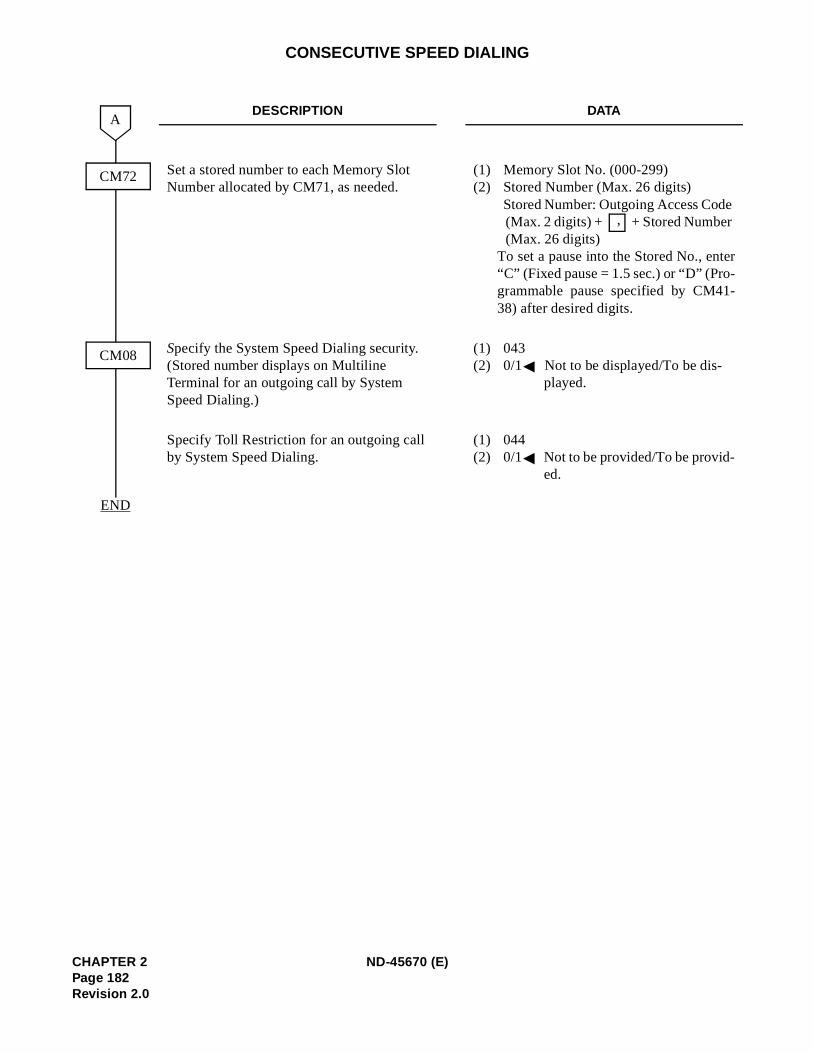
r
CONSECUTIVE SPEED DIALING
DESCRIPTION DATA
Set a stored number to each Memory Slot Number allocated by CM71, as needed.
(1) Memory Slot No. (000-299) (2) Stored Number (Max. 26 digits)
Stored Number: Outgoing Access Code(Max. 2 digits) + + Stored Number (Max. 26 digits)
To set a pause into the Stored No., ente“C” (Fixed pause = 1.5 sec.) or “D” (Pro-grammable pause specified by CM41-38) after desired digits.
Specify the System Speed Dialing security. (Stored number displays on Multiline Terminal for an outgoing call by System Speed Dialing.)
(1) 043 (2) 0/1 Not to be displayed/To be dis-
played.
Specify Toll Restriction for an outgoing call by System Speed Dialing.
(1) 044 (2) 0/1 Not to be provided/To be provid-
ed.
CM72
A
END
CM08
,
CHAPTER 2 ND-45670 (E)Page 182Revision 2.0
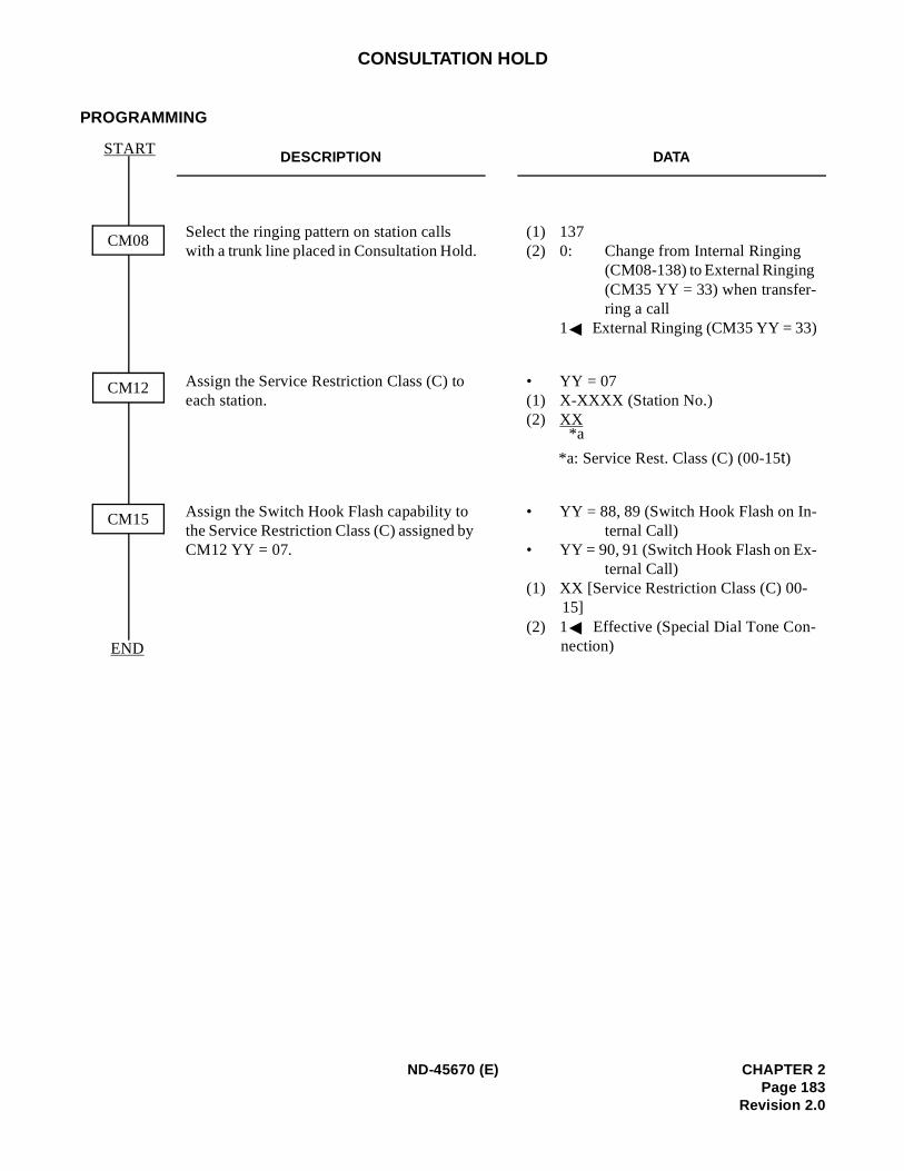
CONSULTATION HOLD
PROGRAMMING
DESCRIPTION DATA
Select the ringing pattern on station calls with a trunk line placed in Consultation Hold.
(1) 137 (2) 0: Change from Internal Ringing
(CM08-138) to External Ringing (CM35 YY = 33) when transfer-ring a call
1 External Ringing (CM35 YY = 33)
Assign the Service Restriction Class (C) to each station.
• YY = 07(1) X-XXXX (Station No.)(2) XX
*a: Service Rest. Class (C) (00-15t)
Assign the Switch Hook Flash capability to the Service Restriction Class (C) assigned by CM12 YY = 07.
• YY = 88, 89 (Switch Hook Flash on In-ternal Call)
• YY = 90, 91 (Switch Hook Flash on Ex-ternal Call)
(1) XX [Service Restriction Class (C) 00-15]
(2) 1 Effective (Special Dial Tone Con-nection)END
CM08
CM12
CM15
START
*a
ND-45670 (E) CHAPTER 2Page 183
Revision 2.0
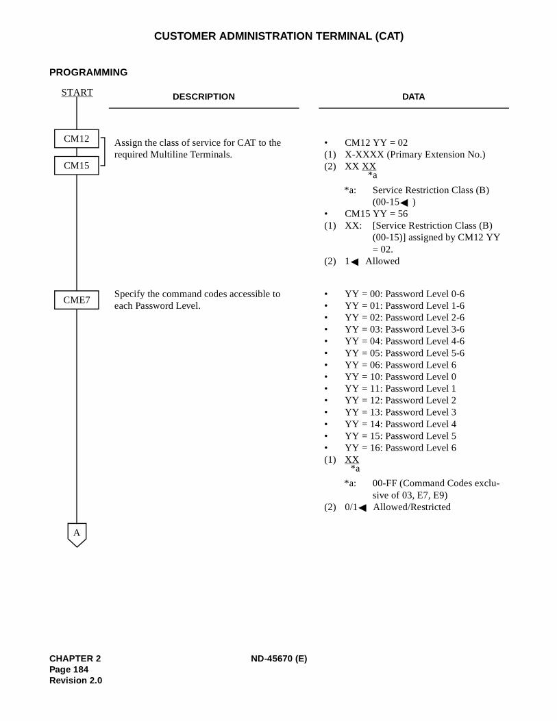
CUSTOMER ADMINISTRATION TERMINAL (CAT)
PROGRAMMING
DESCRIPTION DATA
Assign the class of service for CAT to the required Multiline Terminals.
• CM12 YY = 02 (1) X-XXXX (Primary Extension No.)(2) XX XX
*a: Service Restriction Class (B) (00-15 )
• CM15 YY = 56 (1) XX: [Service Restriction Class (B)
(00-15)] assigned by CM12 YY = 02.
(2) 1 Allowed
Specify the command codes accessible to each Password Level.
• YY = 00: Password Level 0-6• YY = 01: Password Level 1-6• YY = 02: Password Level 2-6• YY = 03: Password Level 3-6• YY = 04: Password Level 4-6• YY = 05: Password Level 5-6• YY = 06: Password Level 6• YY = 10: Password Level 0• YY = 11: Password Level 1• YY = 12: Password Level 2• YY = 13: Password Level 3• YY = 14: Password Level 4• YY = 15: Password Level 5• YY = 16: Password Level 6(1) XX
*a: 00-FF (Command Codes exclu-sive of 03, E7, E9)
(2) 0/1 Allowed/Restricted
A
CM12
CM15
CME7
START
*a
*a
CHAPTER 2 ND-45670 (E)Page 184Revision 2.0
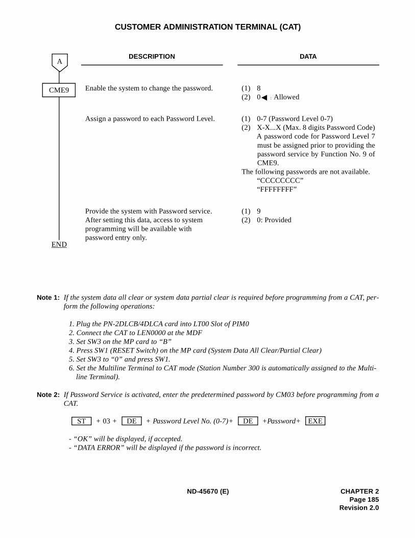
, per-
ulti-
from a
CUSTOMER ADMINISTRATION TERMINAL (CAT)
Note 1: If the system data all clear or system data partial clear is required before programming from a CATform the following operations:
1. Plug the PN-2DLCB/4DLCA card into LT00 Slot of PIM0 2. Connect the CAT to LEN0000 at the MDF3. Set SW3 on the MP card to “B”4. Press SW1 (RESET Switch) on the MP card (System Data All Clear/Partial Clear)5. Set SW3 to “0” and press SW1.6. Set the Multiline Terminal to CAT mode (Station Number 300 is automatically assigned to the M
line Terminal).
Note 2: If Password Service is activated, enter the predetermined password by CM03 before programmingCAT.
+ 03 + + Password Level No. (0-7)+ +Password+
- “OK” will be displayed, if accepted.- “DATA ERROR” will be displayed if the password is incorrect.
DESCRIPTION DATA
Enable the system to change the password. (1) 8 (2) 0 : Allowed
Assign a password to each Password Level. (1) 0-7 (Password Level 0-7)(2) X-X...X (Max. 8 digits Password Code)
A password code for Password Level 7must be assigned prior to providing thepassword service by Function No. 9 ofCME9.
The following passwords are not available.“CCCCCCCC”“FFFFFFFF”
Provide the system with Password service. After setting this data, access to system programming will be available with password entry only.
(1) 9 (2) 0: Provided
END
A
CME9
ST DE DE EXE
ND-45670 (E) CHAPTER 2Page 185
Revision 2.0
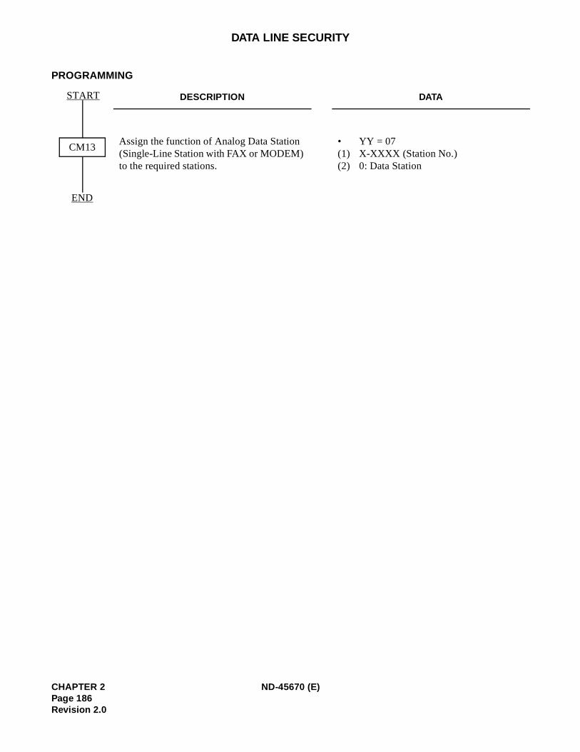
DATA LINE SECURITY
PROGRAMMING
DESCRIPTION DATA
Assign the function of Analog Data Station (Single-Line Station with FAX or MODEM) to the required stations.
• YY = 07(1) X-XXXX (Station No.)(2) 0: Data Station
END
CM13
START
CHAPTER 2 ND-45670 (E)Page 186Revision 2.0
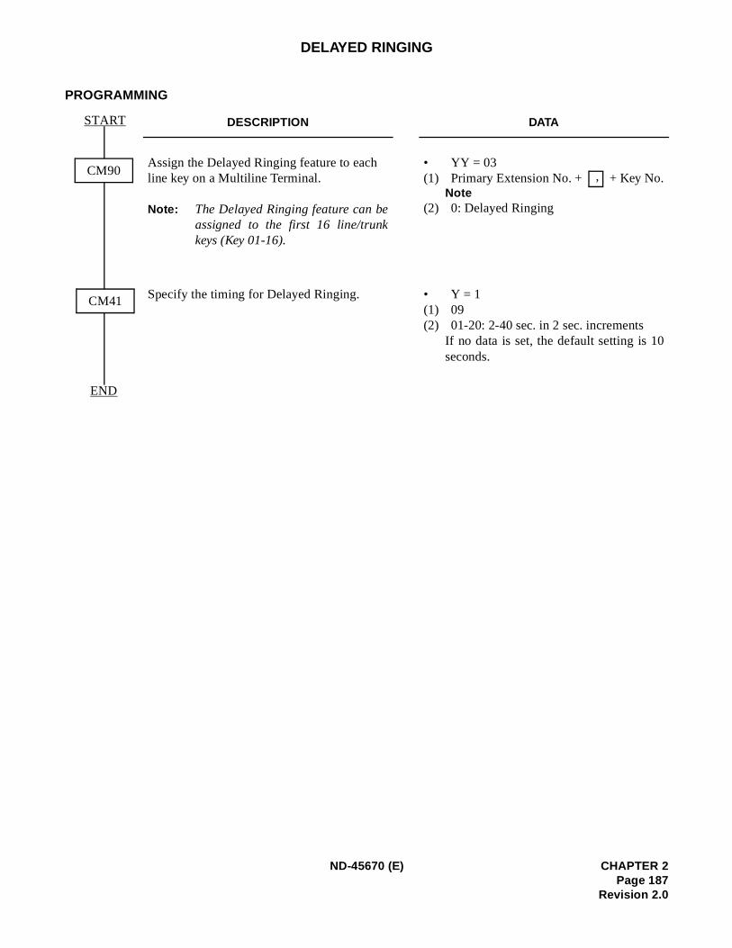
DELAYED RINGING
PROGRAMMING
DESCRIPTION DATA
Assign the Delayed Ringing feature to each line key on a Multiline Terminal.
Note: The Delayed Ringing feature can beassigned to the first 16 line/trunkkeys (Key 01-16).
• YY = 03(1) Primary Extension No. + + Key No.
Note(2) 0: Delayed Ringing
Specify the timing for Delayed Ringing. • Y = 1(1) 09(2) 01-20: 2-40 sec. in 2 sec. increments
If no data is set, the default setting is 10seconds.
END
CM90
START
CM41
,
ND-45670 (E) CHAPTER 2Page 187
Revision 2.0

DIAGNOSTICS
PROGRAMMING
Refer to the Maintenance Manual.
CHAPTER 2 ND-45670 (E)Page 188Revision 2.0
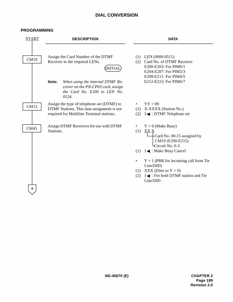
DIAL CONVERSION
PROGRAMMING
DESCRIPTION DATA
Assign the Card Number of the DTMF Receiver to the required LENs.
Note: When using the internal DTMF Re-ceiver on the PN-CP03 card, assignthe Card No. E200 to LEN No.0124.
(1) LEN (0000-0511)(2) Card No. of DTMF Receiver
E200-E203: For PIM0/1 E204-E207: For PIM2/3 E208-E211: For PIM4/5 E212-E215: For PIM6/7
Assign the type of telephone set (DTMF) to DTMF Stations. This data assignment is not required for Multiline Terminal stations.
• YY = 00(1) X-XXXX (Station No.)(2) 3 : DTMF Telephone set
Assign DTMF Receivers for use with DTMF Stations.
• Y = 0 (Make Busy)(1) XX X
Card No. 00-15 assigned by CM10 (E200-E215)Circuit No. 0-3
(1) 1 : Make Busy Cancel
• Y = 1 (PBR for incoming call from Tie Line/DID)
(1) XXX (Ditto to Y = 0)(2) 1 : For both DTMF station and Tie
Line/DID
A
CM10
CM12
CM45
START
INITIAL
ND-45670 (E) CHAPTER 2Page 189
Revision 2.0
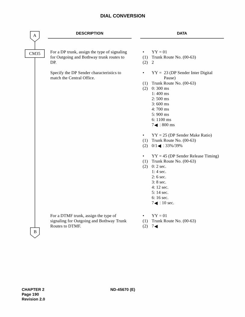
DIAL CONVERSION
DESCRIPTION DATA
For a DP trunk, assign the type of signaling for Outgoing and Bothway trunk routes to DP.
Specify the DP Sender characteristics to match the Central Office.
• YY = 01(1) Trunk Route No. (00-63) (2) 2
• YY = 23 (DP Sender Inter Digital Pause)
(1) Trunk Route No. (00-63) (2) 0: 300 ms
1: 400 ms 2: 500 ms 3: 600 ms 4: 700 ms 5: 900 ms 6: 1100 ms 7 : 800 ms
• YY = 25 (DP Sender Make Ratio) (1) Trunk Route No. (00-63) (2) 0/1 : 33%/39%
• YY = 45 (DP Sender Release Timing) (1) Trunk Route No. (00-63)(2) 0: 2 sec.
1: 4 sec. 2: 6 sec. 3: 8 sec. 4: 12 sec. 5: 14 sec. 6: 16 sec. 7 : 10 sec.
For a DTMF trunk, assign the type of signaling for Outgoing and Bothway Trunk Routes to DTMF.
• YY = 01(1) Trunk Route No. (00-63) (2) 7
B
A
CM35
CHAPTER 2 ND-45670 (E)Page 190Revision 2.0
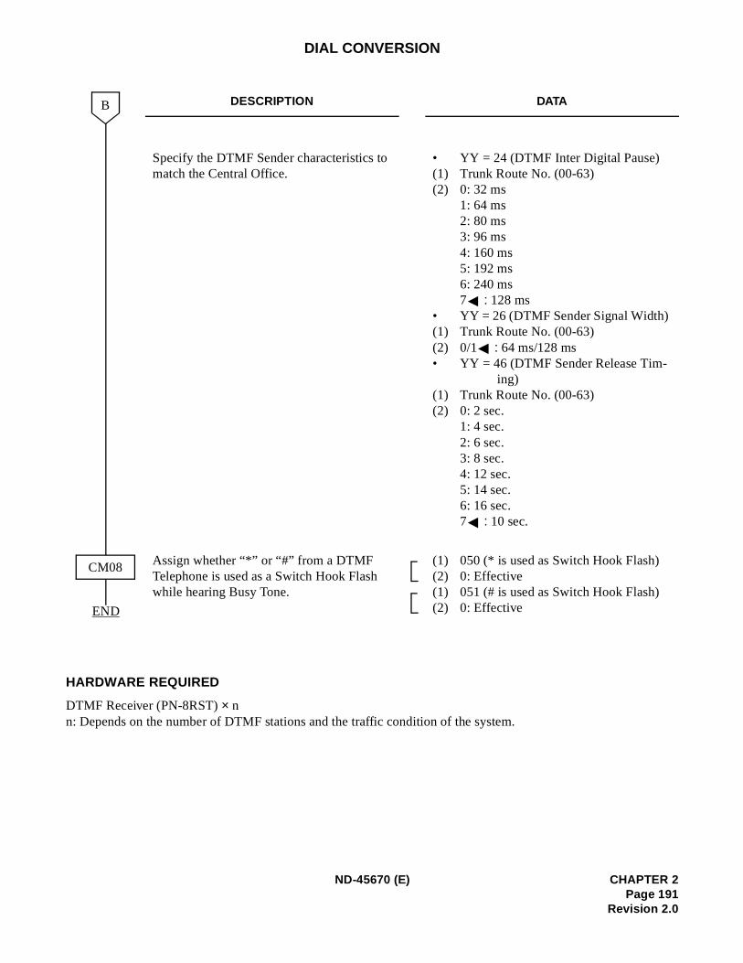
DIAL CONVERSION
HARDWARE REQUIRED
DTMF Receiver (PN-8RST) × n n: Depends on the number of DTMF stations and the traffic condition of the system.
DESCRIPTION DATA
Specify the DTMF Sender characteristics to match the Central Office.
• YY = 24 (DTMF Inter Digital Pause) (1) Trunk Route No. (00-63)(2) 0: 32 ms
1: 64 ms 2: 80 ms 3: 96 ms 4: 160 ms 5: 192 ms 6: 240 ms 7 : 128 ms
• YY = 26 (DTMF Sender Signal Width) (1) Trunk Route No. (00-63)(2) 0/1 : 64 ms/128 ms • YY = 46 (DTMF Sender Release Tim-
ing) (1) Trunk Route No. (00-63) (2) 0: 2 sec.
1: 4 sec. 2: 6 sec. 3: 8 sec. 4: 12 sec. 5: 14 sec. 6: 16 sec. 7 : 10 sec.
Assign whether “*” or “#” from a DTMF Telephone is used as a Switch Hook Flash while hearing Busy Tone.
(1) 050 (* is used as Switch Hook Flash) (2) 0: Effective(1) 051 (# is used as Switch Hook Flash) (2) 0: EffectiveEND
B
CM08
ND-45670 (E) CHAPTER 2Page 191
Revision 2.0

DIRECT DIGITAL INTERFACE
PROGRAMMING
Refer to the DDI System Manual.
HARDWARE REQUIRED
Refer to the DDI System Manual.
CHAPTER 2 ND-45670 (E)Page 192Revision 2.0
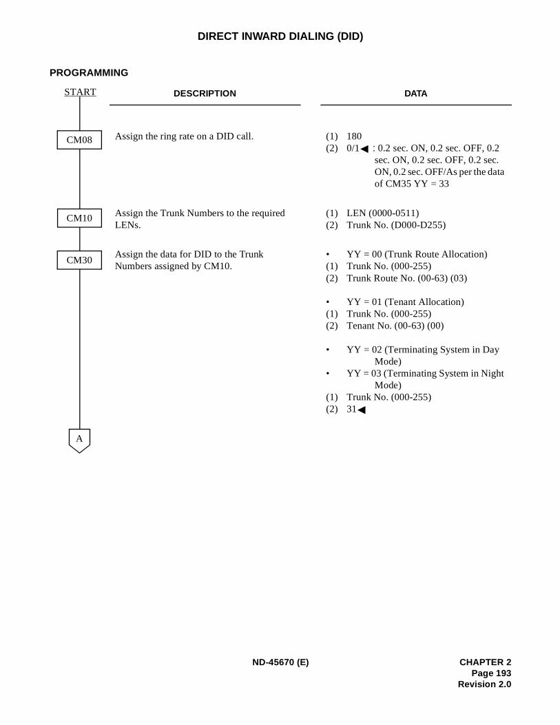
DIRECT INWARD DIALING (DID)
PROGRAMMING
DESCRIPTION DATA
Assign the ring rate on a DID call. (1) 180(2) 0/1 : 0.2 sec. ON, 0.2 sec. OFF, 0.2
sec. ON, 0.2 sec. OFF, 0.2 sec. ON, 0.2 sec. OFF/As per the dataof CM35 YY = 33
Assign the Trunk Numbers to the required LENs.
(1) LEN (0000-0511) (2) Trunk No. (D000-D255)
Assign the data for DID to the Trunk Numbers assigned by CM10.
• YY = 00 (Trunk Route Allocation)(1) Trunk No. (000-255)(2) Trunk Route No. (00-63) (03)
• YY = 01 (Tenant Allocation)(1) Trunk No. (000-255)(2) Tenant No. (00-63) (00)
• YY = 02 (Terminating System in Day Mode)
• YY = 03 (Terminating System in Night Mode)
(1) Trunk No. (000-255)(2) 31
CM08
CM10
CM30
START
A
ND-45670 (E) CHAPTER 2Page 193
Revision 2.0
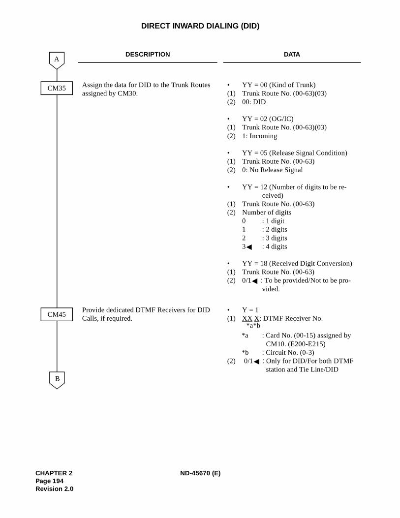
DIRECT INWARD DIALING (DID)
DESCRIPTION DATA
Assign the data for DID to the Trunk Routes assigned by CM30.
• YY = 00 (Kind of Trunk)(1) Trunk Route No. (00-63)(03)(2) 00: DID
• YY = 02 (OG/IC)(1) Trunk Route No. (00-63)(03) (2) 1: Incoming
• YY = 05 (Release Signal Condition) (1) Trunk Route No. (00-63)(2) 0: No Release Signal
• YY = 12 (Number of digits to be re-ceived)
(1) Trunk Route No. (00-63) (2) Number of digits
0 : 1 digit1 : 2 digits 2 : 3 digits 3 : 4 digits
• YY = 18 (Received Digit Conversion)(1) Trunk Route No. (00-63)(2) 0/1 : To be provided/Not to be pro-
vided.
Provide dedicated DTMF Receivers for DID Calls, if required.
• Y = 1(1) XX X: DTMF Receiver No.
*a : Card No. (00-15) assigned by CM10. (E200-E215)
*b : Circuit No. (0-3)(2) 0/1 : Only for DID/For both DTMF
station and Tie Line/DIDB
A
CM35
CM45
*b*a
CHAPTER 2 ND-45670 (E)Page 194Revision 2.0
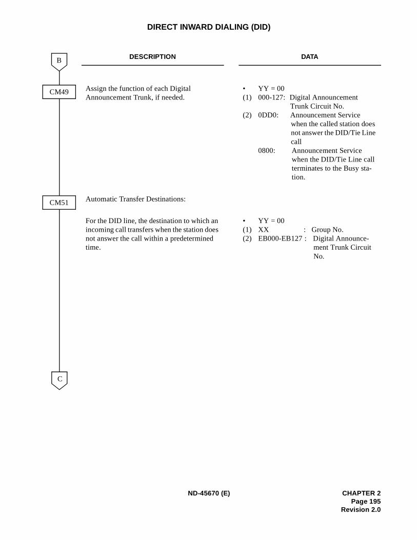
DIRECT INWARD DIALING (DID)
DESCRIPTION DATA
Assign the function of each Digital Announcement Trunk, if needed.
• YY = 00(1) 000-127: Digital Announcement
Trunk Circuit No. (2) 0DD0: Announcement Service
when the called station does not answer the DID/Tie Line call
0800: Announcement Service when the DID/Tie Line call terminates to the Busy sta-tion.
Automatic Transfer Destinations:
For the DID line, the destination to which an incoming call transfers when the station does not answer the call within a predetermined time.
• YY = 00(1) XX : Group No. (2) EB000-EB127 : Digital Announce-
ment Trunk Circuit No.
C
B
CM49
CM51
ND-45670 (E) CHAPTER 2Page 195
Revision 2.0
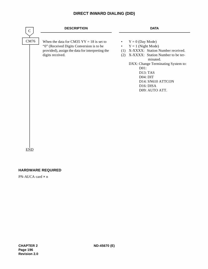
DIRECT INWARD DIALING (DID)
HARDWARE REQUIRED
PN-AUCA card × n
DESCRIPTION DATA
When the data for CM35 YY = 18 is set to “0” (Received Digits Conversion is to be provided), assign the data for interpreting the digits received.
• Y = 0 (Day Mode) • Y = 1 (Night Mode) (1) X-XXXX: Station Number received.(2) X-XXXX: Station Number to be ter-
minated. DXX: Change Terminating System to:
D01:D13: TAS D04: DIT D14: SN610 ATTCOND16: DISAD09: AUTO ATT.
END
CM76
C
CHAPTER 2 ND-45670 (E)Page 196Revision 2.0
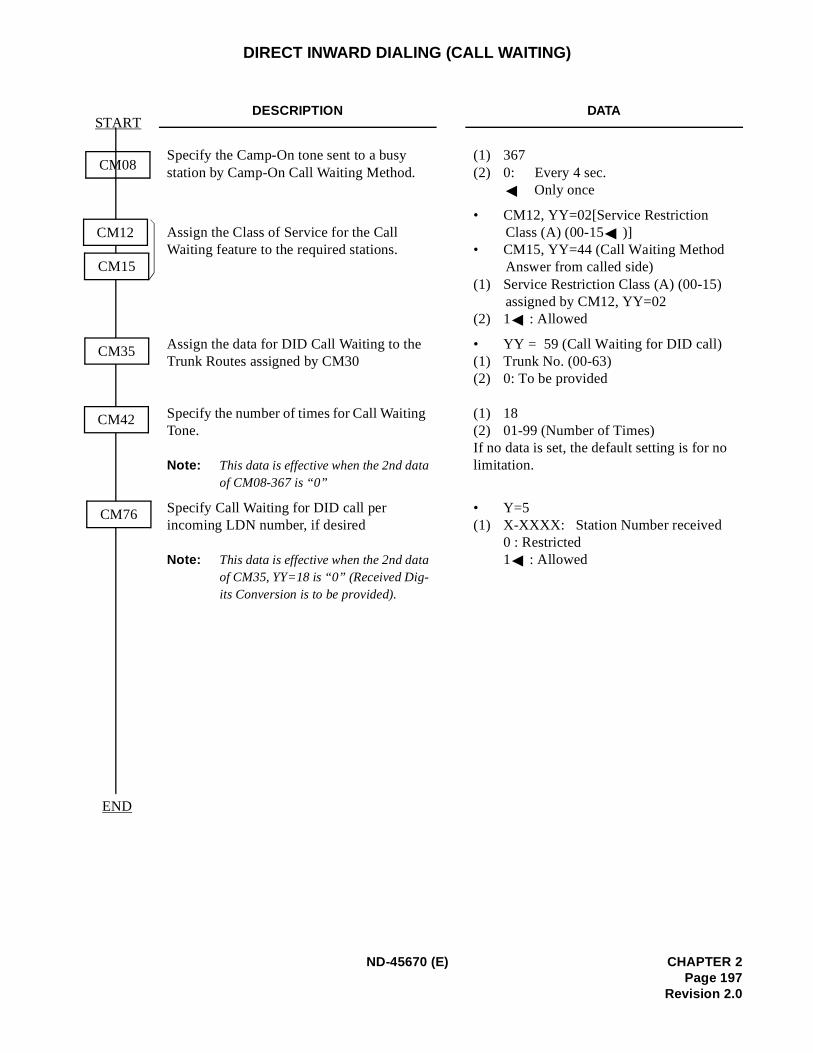
DIRECT INWARD DIALING (CALL WAITING)
DESCRIPTION DATA
Specify the Camp-On tone sent to a busy station by Camp-On Call Waiting Method.
(1) 367 (2) 0: Every 4 sec.
Only once
Assign the Class of Service for the Call Waiting feature to the required stations.
• CM12, YY=02[Service Restriction Class (A) (00-15 )]
• CM15, YY=44 (Call Waiting Method Answer from called side)
(1) Service Restriction Class (A) (00-15) assigned by CM12, YY=02
(2) 1 : Allowed
Assign the data for DID Call Waiting to the Trunk Routes assigned by CM30
Specify the number of times for Call Waiting Tone.
Note: This data is effective when the 2nd dataof CM08-367 is “0”
• YY = 59 (Call Waiting for DID call) (1) Trunk No. (00-63) (2) 0: To be provided
(1) 18(2) 01-99 (Number of Times)If no data is set, the default setting is for no limitation.
Specify Call Waiting for DID call per incoming LDN number, if desired
Note: This data is effective when the 2nd dataof CM35, YY=18 is “0” (Received Dig-its Conversion is to be provided).
• Y=5(1) X-XXXX: Station Number received
0 : Restricted1 : Allowed
CM08
END
START
CM12
CM15
CM35
CM42
CM76
ND-45670 (E) CHAPTER 2Page 197
Revision 2.0
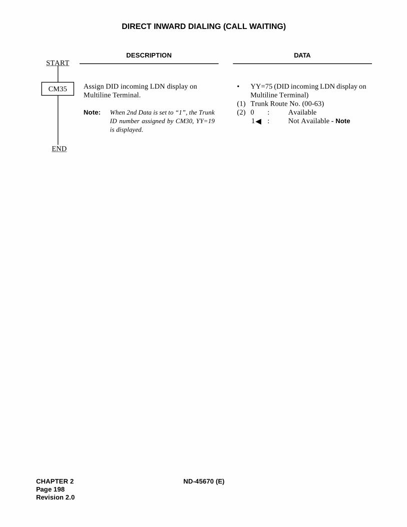
DIRECT INWARD DIALING (CALL WAITING)
DESCRIPTION DATA
Assign DID incoming LDN display on Multiline Terminal.
Note: When 2nd Data is set to “1”, the TrunkID number assigned by CM30, YY=19is displayed.
• YY=75 (DID incoming LDN display on Multiline Terminal)
(1) Trunk Route No. (00-63)(2) 0 : Available
1 : Not Available - Note
END
START
CM35
CHAPTER 2 ND-45670 (E)Page 198Revision 2.0
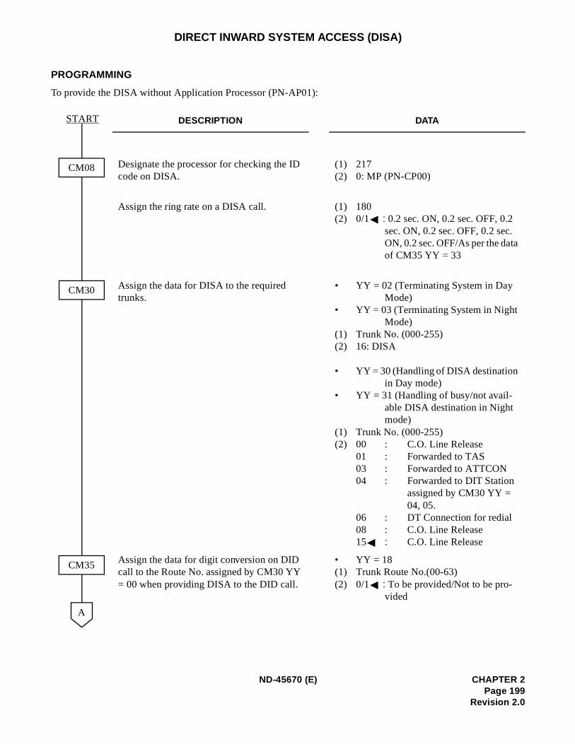
DIRECT INWARD SYSTEM ACCESS (DISA)
PROGRAMMING
To provide the DISA without Application Processor (PN-AP01):
DESCRIPTION DATA
Designate the processor for checking the ID code on DISA.
(1) 217 (2) 0: MP (PN-CP00)
Assign the ring rate on a DISA call. (1) 180 (2) 0/1 : 0.2 sec. ON, 0.2 sec. OFF, 0.2
sec. ON, 0.2 sec. OFF, 0.2 sec. ON, 0.2 sec. OFF/As per the dataof CM35 YY = 33
Assign the data for DISA to the required trunks.
• YY = 02 (Terminating System in Day Mode)
• YY = 03 (Terminating System in Night Mode)
(1) Trunk No. (000-255) (2) 16: DISA
• YY = 30 (Handling of DISA destination in Day mode)
• YY = 31 (Handling of busy/not avail-able DISA destination in Night mode)
(1) Trunk No. (000-255)(2) 00 : C.O. Line Release
01 : Forwarded to TAS03 : Forwarded to ATTCON 04 : Forwarded to DIT Station
assigned by CM30 YY = 04, 05.
06 : DT Connection for redial08 : C.O. Line Release 15 : C.O. Line Release
Assign the data for digit conversion on DID call to the Route No. assigned by CM30 YY = 00 when providing DISA to the DID call.
• YY = 18(1) Trunk Route No.(00-63)(2) 0/1 : To be provided/Not to be pro-
vided
CM08
CM30
CM35
START
A
ND-45670 (E) CHAPTER 2Page 199
Revision 2.0
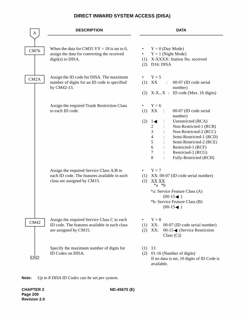
DIRECT INWARD SYSTEM ACCESS (DISA)
Note: Up to 8 DISA ID Codes can be set per system.
DESCRIPTION DATA
When the data for CM35 YY = 18 is set to 0, assign the data for converting the received digit(s) to DISA.
• Y = 0 (Day Mode) • Y = 1 (Night Mode) (1) X-XXXX: Station No. received(2) D16: DISA
Assign the ID code for DISA. The maximum number of digits for an ID code is specified by CM42-13.
• Y = 5(1) XX : 00-07 (ID code serial
number) (2) X-X...X : ID code (Max. 16 digits)
Assign the required Trunk Restriction Class to each ID code.
• Y = 6(1) XX : 00-07 (ID code serial
number) (2) 1 : Unrestricted (RCA)
2 : Non-Restricted-1 (RCB)3 : Non-Restricted-2 (RCC)4 : Semi-Restricted-1 (RCD) 5 : Semi-Restricted-2 (RCE) 6 : Restricted-1 (RCF)7 : Restricted-2 (RCG)8 : Fully-Restricted (RCH)
Assign the required Service Class A/B to each ID code. The features available in each class are assigned by CM15.
• Y = 7(1) XX: 00-07 (ID code serial number) (2) XX XX
*a: Service Feature Class (A) (00-15 )
*b: Service Feature Class (B) (00-15 )
Assign the required Service Class C to each ID code. The features available in each class are assigned by CM15.
• Y = 8(1) XX: 00-07 (ID code serial number) (2) XX: 00-15 (Service Restriction
Class (C))
Specify the maximum number of digits for ID Codes on DISA.
(1) 13(2) 01-16 (Number of digits)
If no data is set, 10 digits of ID Code is available.
CM76
CM2A
CM42
A
END
*b*a
CHAPTER 2 ND-45670 (E)Page 200Revision 2.0
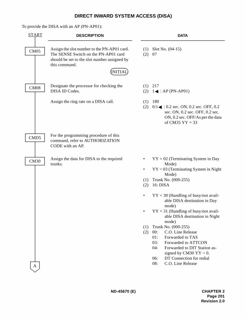
DIRECT INWARD SYSTEM ACCESS (DISA)
To provide the DISA with an AP (PN-AP01):
DESCRIPTION DATA
Assign the slot number to the PN-AP01 card. The SENSE Switch on the PN-AP01 card should be set to the slot number assigned by this command.
(1) Slot No. (04-15)(2) 07
Designate the processor for checking the DISA ID Codes.
Assign the ring rate on a DISA call.
(1) 217 (2) 1 : AP (PN-AP01)
(1) 180 (2) 0/1 : 0.2 sec. ON, 0.2 sec. OFF, 0.2
sec. ON, 0.2 sec. OFF, 0.2 sec. ON, 0.2 sec. OFF/As per the dataof CM35 YY = 33
For the programming procedure of this command, refer to AUTHORIZATION CODE with an AP.
Assign the data for DISA to the required trunks.
• YY = 02 (Terminating System in Day Mode)
• YY = 03 (Terminating System in Night Mode)
(1) Trunk No. (000-255) (2) 16: DISA
• YY = 30 (Handling of busy/not avail-able DISA destination in Day mode)
• YY = 31 (Handling of busy/not avail-able DISA destination in Night mode)
(1) Trunk No. (000-255)(2) 00: C.O. Line Release
01: Forwarded to TAS03: Forwarded to ATTCON 04: Forwarded to DIT Station as-
signed by CM30 YY = 0. 06: DT Connection for redial08: C.O. Line Release
CM05
CM08
CM30
START
A
CMD5
INITIAL
ND-45670 (E) CHAPTER 2Page 201
Revision 2.0
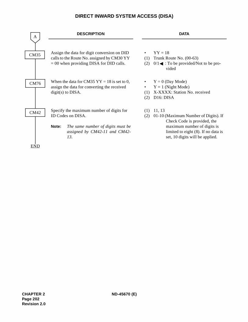
DIRECT INWARD SYSTEM ACCESS (DISA)
DESCRIPTION DATA
Assign the data for digit conversion on DID calls to the Route No. assigned by CM30 YY = 00 when providing DISA for DID calls.
• YY = 18(1) Trunk Route No. (00-63)(2) 0/1 : To be provided/Not to be pro-
vided
When the data for CM35 YY = 18 is set to 0, assign the data for converting the received digit(s) to DISA.
• Y = 0 (Day Mode) • Y = 1 (Night Mode) (1) X-XXXX: Station No. received (2) D16: DISA
Specify the maximum number of digits for ID Codes on DISA.
Note: The same number of digits must beassigned by CM42-11 and CM42-13.
(1) 11, 13(2) 01-10 (Maximum Number of Digits). If
Check Code is provided, the maximum number of digits is limited to eight (8). If no data is set, 10 digits will be applied.
CM76
CM42
A
END
CM35
CHAPTER 2 ND-45670 (E)Page 202Revision 2.0
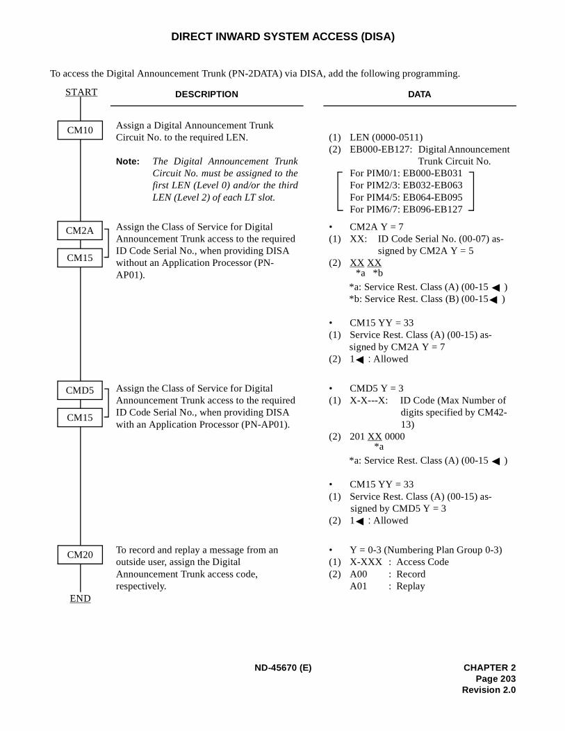
DIRECT INWARD SYSTEM ACCESS (DISA)
To access the Digital Announcement Trunk (PN-2DATA) via DISA, add the following programming.
DESCRIPTION DATA
Assign a Digital Announcement Trunk Circuit No. to the required LEN.
Note: The Digital Announcement TrunkCircuit No. must be assigned to thefirst LEN (Level 0) and/or the thirdLEN (Level 2) of each LT slot.
(1) LEN (0000-0511) (2) EB000-EB127: Digital Announcement
Trunk Circuit No. For PIM0/1: EB000-EB031 For PIM2/3: EB032-EB063For PIM4/5: EB064-EB095 For PIM6/7: EB096-EB127
Assign the Class of Service for Digital Announcement Trunk access to the required ID Code Serial No., when providing DISA without an Application Processor (PN-AP01).
• CM2A Y = 7 (1) XX: ID Code Serial No. (00-07) as-
signed by CM2A Y = 5(2) XX XX
*a: Service Rest. Class (A) (00-15 )*b: Service Rest. Class (B) (00-15 )
• CM15 YY = 33 (1) Service Rest. Class (A) (00-15) as-
signed by CM2A Y = 7 (2) 1 : Allowed
Assign the Class of Service for Digital Announcement Trunk access to the required ID Code Serial No., when providing DISA with an Application Processor (PN-AP01).
• CMD5 Y = 3 (1) X-X---X: ID Code (Max Number of
digits specified by CM42-13)
(2) 201 XX 0000
*a: Service Rest. Class (A) (00-15 )
• CM15 YY = 33 (1) Service Rest. Class (A) (00-15) as-
signed by CMD5 Y = 3 (2) 1 : Allowed
To record and replay a message from an outside user, assign the Digital Announcement Trunk access code, respectively.
• Y = 0-3 (Numbering Plan Group 0-3)(1) X-XXX : Access Code (2) A00 : Record
A01 : Replay
CM10
END
START
CM20
CM2A
CM15
CMD5
CM15
*b*a
*a
ND-45670 (E) CHAPTER 2Page 203
Revision 2.0
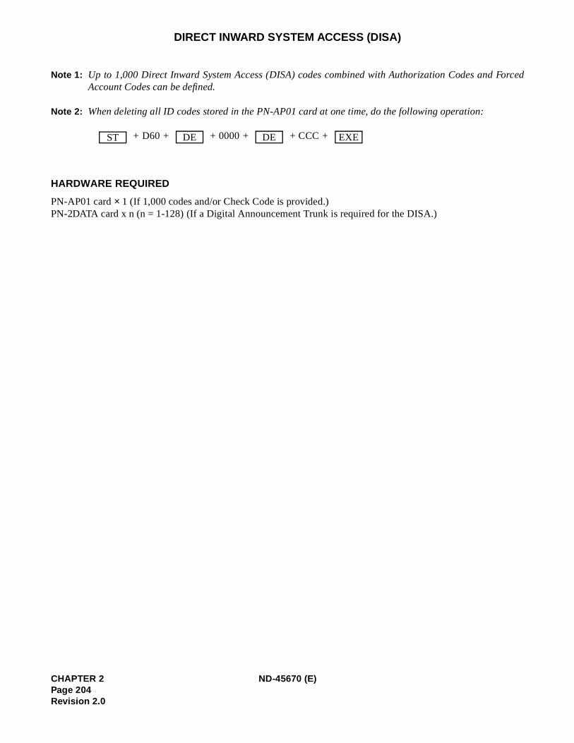
Forced
DIRECT INWARD SYSTEM ACCESS (DISA)
Note 1: Up to 1,000 Direct Inward System Access (DISA) codes combined with Authorization Codes andAccount Codes can be defined.
Note 2: When deleting all ID codes stored in the PN-AP01 card at one time, do the following operation:
+ D60 + + 0000 + + CCC +
HARDWARE REQUIRED
PN-AP01 card × 1 (If 1,000 codes and/or Check Code is provided.)PN-2DATA card x n (n = 1-128) (If a Digital Announcement Trunk is required for the DISA.)
ST DE DE EXE
CHAPTER 2 ND-45670 (E)Page 204Revision 2.0
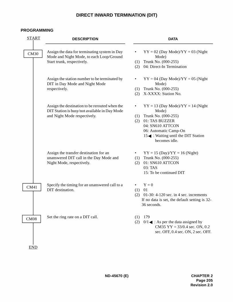
-
.
DIRECT INWARD TERMINATION (DIT)
PROGRAMMING
DESCRIPTION DATA
Assign the data for terminating system in Day Mode and Night Mode, to each Loop/Ground Start trunk, respectively.
• YY = 02 (Day Mode)/YY = 03 (Night Mode)
(1) Trunk No. (000-255)(2) 04: Direct-In Termination
Assign the station number to be terminated by DIT in Day Mode and Night Mode respectively.
• YY = 04 (Day Mode)/YY = 05 (Night Mode)
(1) Trunk No. (000-255)(2) X-XXXX: Station No.
Assign the destination to be rerouted when the DIT Station is busy/not available in Day Mode and Night Mode respectively.
• YY = 13 (Day Mode)/YY = 14 (Night Mode)
(1) Trunk No. (000-255)(2) 01: TAS BUZZER
04: SN610 ATTCON06: Automatic Camp-On 15 : Waiting until the DIT Station
becomes idle.
Assign the transfer destination for an unanswered DIT call in the Day Mode and Night Mode, respectively.
• YY = 15 (Day)/YY = 16 (Night)(1) Trunk No. (000-255)(2) 01: SN610 ATTCON
03: TAS15: To be continued DIT
Specify the timing for an unanswered call to a DIT destination.
• Y = 0(1) 01(2) 01-30: 4-120 sec. in 4 sec. increments
If no data is set, the default setting is 3236 seconds.
Set the ring rate on a DIT call. (1) 179 (2) 0/1 : As per the data assigned by
CM35 YY = 33/0.4 sec. ON, 0.2 sec. OFF, 0.4 sec. ON, 2 sec. OFF
CM30
END
START
CM41
CM08
ND-45670 (E) CHAPTER 2Page 205
Revision 2.0
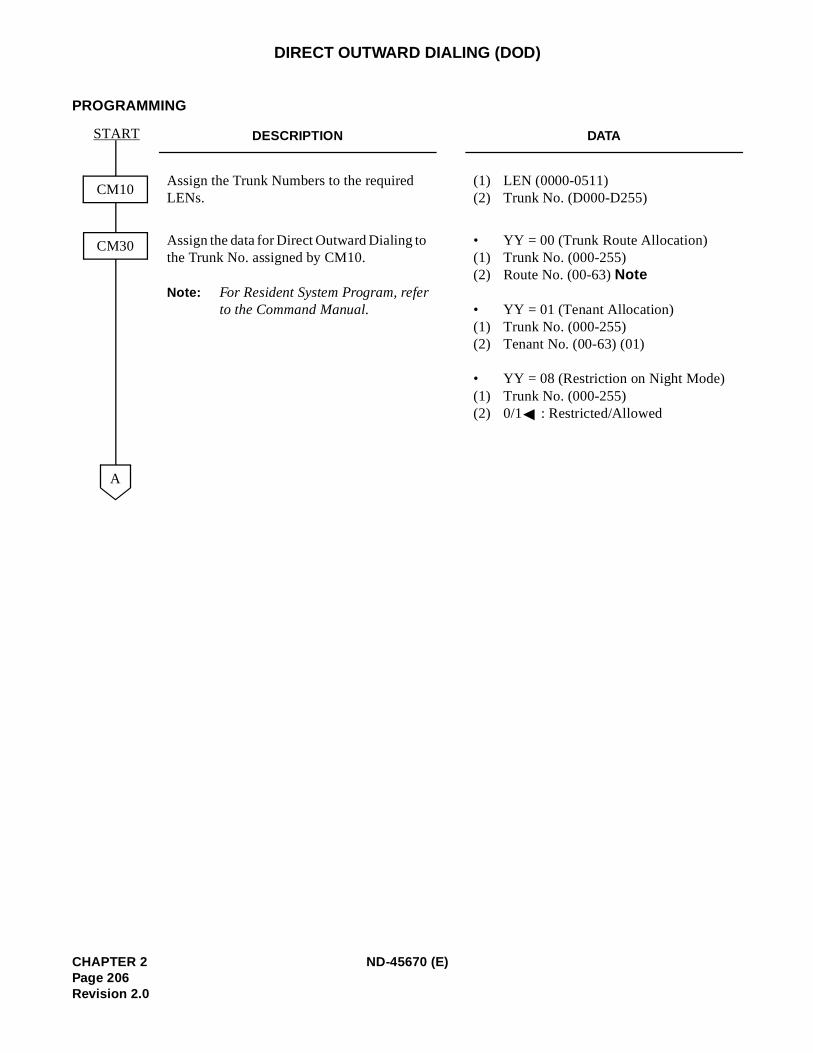
DIRECT OUTWARD DIALING (DOD)
PROGRAMMING
DESCRIPTION DATA
Assign the Trunk Numbers to the required LENs.
(1) LEN (0000-0511) (2) Trunk No. (D000-D255)
Assign the data for Direct Outward Dialing to the Trunk No. assigned by CM10.
Note: For Resident System Program, referto the Command Manual.
• YY = 00 (Trunk Route Allocation) (1) Trunk No. (000-255)(2) Route No. (00-63) Note
• YY = 01 (Tenant Allocation)(1) Trunk No. (000-255)(2) Tenant No. (00-63) (01)
• YY = 08 (Restriction on Night Mode)(1) Trunk No. (000-255)(2) 0/1 : Restricted/Allowed
CM10
CM30
START
A
CHAPTER 2 ND-45670 (E)Page 206Revision 2.0
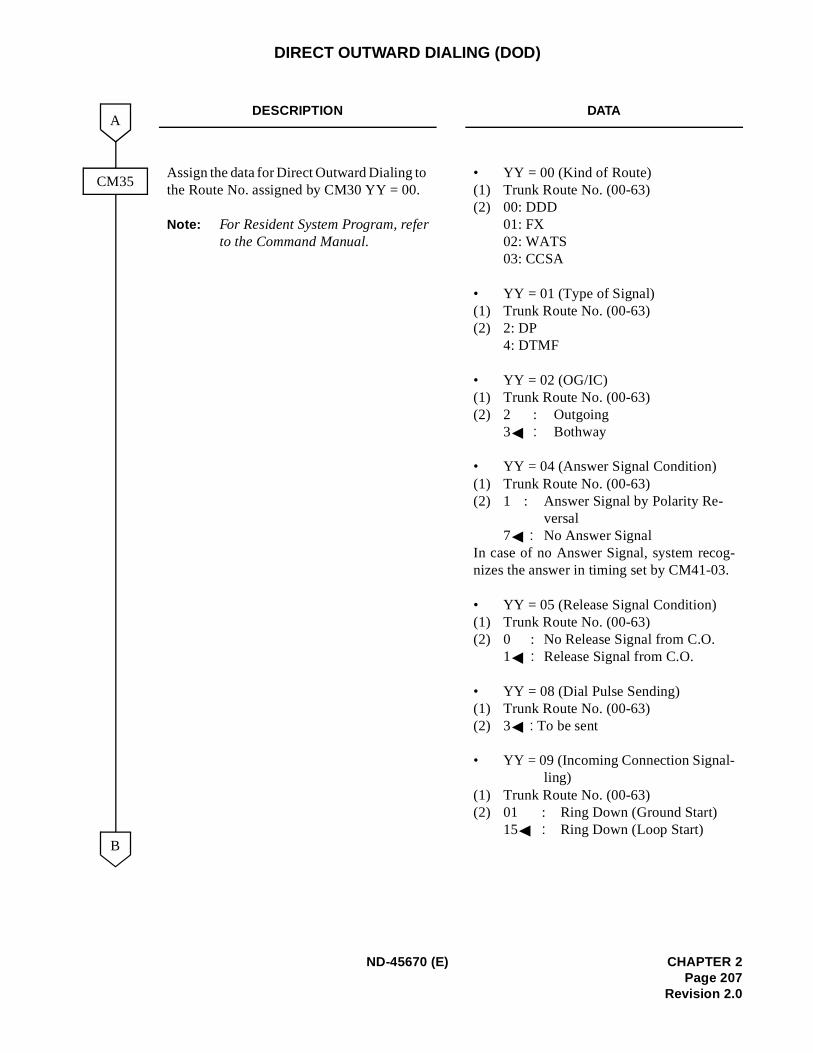
DIRECT OUTWARD DIALING (DOD)
DESCRIPTION DATA
Assign the data for Direct Outward Dialing to the Route No. assigned by CM30 YY = 00.
Note: For Resident System Program, referto the Command Manual.
• YY = 00 (Kind of Route)(1) Trunk Route No. (00-63)(2) 00: DDD
01: FX02: WATS03: CCSA
• YY = 01 (Type of Signal) (1) Trunk Route No. (00-63) (2) 2: DP
4: DTMF
• YY = 02 (OG/IC) (1) Trunk Route No. (00-63)(2) 2 : Outgoing
3 : Bothway
• YY = 04 (Answer Signal Condition)(1) Trunk Route No. (00-63)(2) 1 : Answer Signal by Polarity Re-
versal 7 : No Answer Signal
In case of no Answer Signal, system recog-nizes the answer in timing set by CM41-03.
• YY = 05 (Release Signal Condition) (1) Trunk Route No. (00-63)(2) 0 : No Release Signal from C.O.
1 : Release Signal from C.O.
• YY = 08 (Dial Pulse Sending) (1) Trunk Route No. (00-63) (2) 3 : To be sent
• YY = 09 (Incoming Connection Signal-ling)
(1) Trunk Route No. (00-63) (2) 01 : Ring Down (Ground Start)
15 : Ring Down (Loop Start)
CM35
B
A
ND-45670 (E) CHAPTER 2Page 207
Revision 2.0
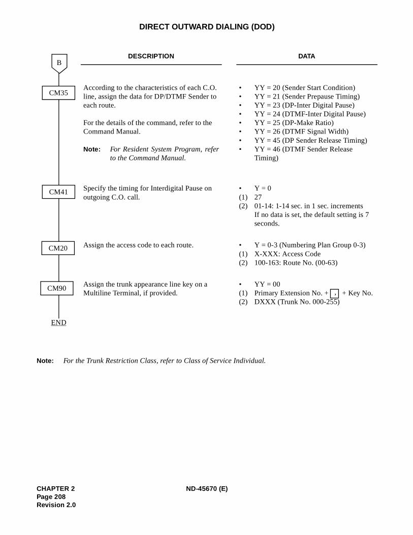
)
DIRECT OUTWARD DIALING (DOD)
Note: For the Trunk Restriction Class, refer to Class of Service Individual.
DESCRIPTION DATA
According to the characteristics of each C.O. line, assign the data for DP/DTMF Sender to each route.
For the details of the command, refer to the Command Manual.
Note: For Resident System Program, referto the Command Manual.
• YY = 20 (Sender Start Condition) • YY = 21 (Sender Prepause Timing) • YY = 23 (DP-Inter Digital Pause) • YY = 24 (DTMF-Inter Digital Pause) • YY = 25 (DP-Make Ratio)• YY = 26 (DTMF Signal Width)• YY = 45 (DP Sender Release Timing) • YY = 46 (DTMF Sender Release
Timing)
Specify the timing for Interdigital Pause on outgoing C.O. call.
• Y = 0(1) 27(2) 01-14: 1-14 sec. in 1 sec. increments
If no data is set, the default setting is 7 seconds.
Assign the access code to each route. • Y = 0-3 (Numbering Plan Group 0-3(1) X-XXX: Access Code(2) 100-163: Route No. (00-63)
Assign the trunk appearance line key on a Multiline Terminal, if provided.
• YY = 00(1) Primary Extension No. + + Key No.(2) DXXX (Trunk No. 000-255)
CM35
B
END
CM20
CM90
CM41
,
CHAPTER 2 ND-45670 (E)Page 208Revision 2.0
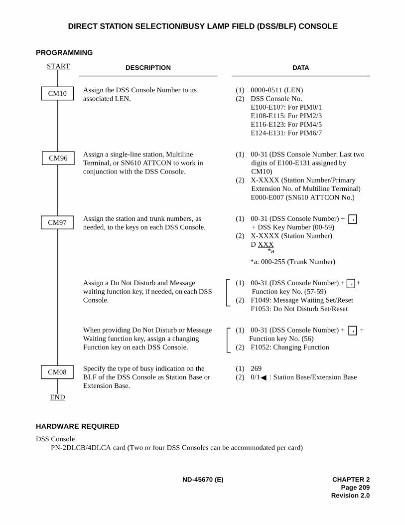
DIRECT STATION SELECTION/BUSY LAMP FIELD (DSS/BLF) CONSOLE
PROGRAMMING
HARDWARE REQUIRED
DSS Console PN-2DLCB/4DLCA card (Two or four DSS Consoles can be accommodated per card)
DESCRIPTION DATA
Assign the DSS Console Number to its associated LEN.
(1) 0000-0511 (LEN)(2) DSS Console No.
E100-E107: For PIM0/1 E108-E115: For PIM2/3 E116-E123: For PIM4/5 E124-E131: For PIM6/7
Assign a single-line station, Multiline Terminal, or SN610 ATTCON to work in conjunction with the DSS Console.
(1) 00-31 (DSS Console Number: Last two digits of E100-E131 assigned by CM10)
(2) X-XXXX (Station Number/Primary Extension No. of Multiline Terminal)E000-E007 (SN610 ATTCON No.)
Assign the station and trunk numbers, as needed, to the keys on each DSS Console.
(1) 00-31 (DSS Console Number) + + DSS Key Number (00-59)
(2) X-XXXX (Station Number)D XXX
*a: 000-255 (Trunk Number)
Assign a Do Not Disturb and Message waiting function key, if needed, on each DSS Console.
(1) 00-31 (DSS Console Number) + + Function key No. (57-59)
(2) F1049: Message Waiting Set/ResetF1053: Do Not Disturb Set/Reset
When providing Do Not Disturb or Message Waiting function key, assign a changing Function key on each DSS Console.
(1) 00-31 (DSS Console Number) + + Function key No. (56)
(2) F1052: Changing Function
Specify the type of busy indication on the BLF of the DSS Console as Station Base or Extension Base.
(1) 269(2) 0/1 : Station Base/Extension Base
CM10
END
START
CM97
CM08
CM96
,
*a
,
,
ND-45670 (E) CHAPTER 2Page 209
Revision 2.0
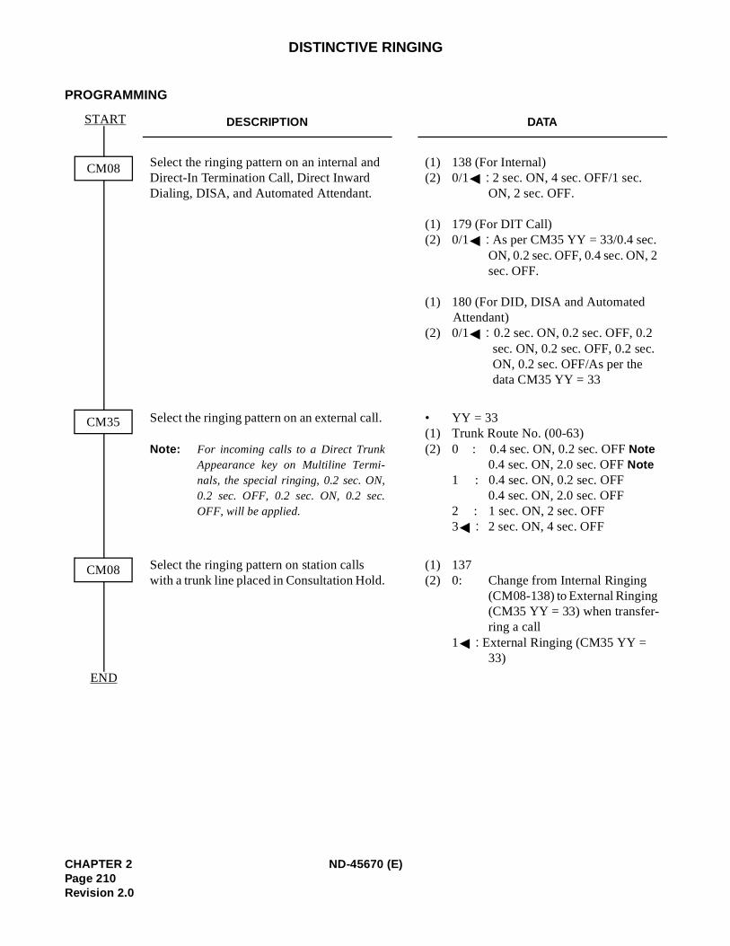
DISTINCTIVE RINGING
PROGRAMMING
DESCRIPTION DATA
Select the ringing pattern on an internal and Direct-In Termination Call, Direct Inward Dialing, DISA, and Automated Attendant.
(1) 138 (For Internal)(2) 0/1 : 2 sec. ON, 4 sec. OFF/1 sec.
ON, 2 sec. OFF.
(1) 179 (For DIT Call)(2) 0/1 : As per CM35 YY = 33/0.4 sec.
ON, 0.2 sec. OFF, 0.4 sec. ON, 2 sec. OFF.
(1) 180 (For DID, DISA and Automated Attendant)
(2) 0/1 : 0.2 sec. ON, 0.2 sec. OFF, 0.2 sec. ON, 0.2 sec. OFF, 0.2 sec. ON, 0.2 sec. OFF/As per the data CM35 YY = 33
Select the ringing pattern on an external call.
Note: For incoming calls to a Direct TrunkAppearance key on Multiline Termi-nals, the special ringing, 0.2 sec. ON,0.2 sec. OFF, 0.2 sec. ON, 0.2 sec.OFF, will be applied.
• YY = 33(1) Trunk Route No. (00-63)(2) 0 : 0.4 sec. ON, 0.2 sec. OFF Note
0.4 sec. ON, 2.0 sec. OFF Note1 : 0.4 sec. ON, 0.2 sec. OFF
0.4 sec. ON, 2.0 sec. OFF 2 : 1 sec. ON, 2 sec. OFF3 : 2 sec. ON, 4 sec. OFF
Select the ringing pattern on station calls with a trunk line placed in Consultation Hold.
(1) 137 (2) 0: Change from Internal Ringing
(CM08-138) to External Ringing (CM35 YY = 33) when transfer-ring a call
1 : External Ringing (CM35 YY = 33)
CM08
END
START
CM35
CM08
CHAPTER 2 ND-45670 (E)Page 210Revision 2.0
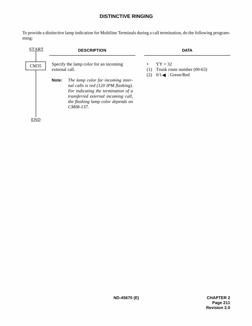
m-
DISTINCTIVE RINGING
To provide a distinctive lamp indication for Multiline Terminals during a call termination, do the following programing:
DESCRIPTION DATA
Specify the lamp color for an incoming external call.
Note: The lamp color for incoming inter-nal calls is red (120 IPM flashing).For indicating the termination of atransferred external incoming call,the flashing lamp color depends onCM08-137.
• YY = 32(1) Trunk route number (00-63) (2) 0/1 : Green/Red
END
START
CM35
ND-45670 (E) CHAPTER 2Page 211
Revision 2.0
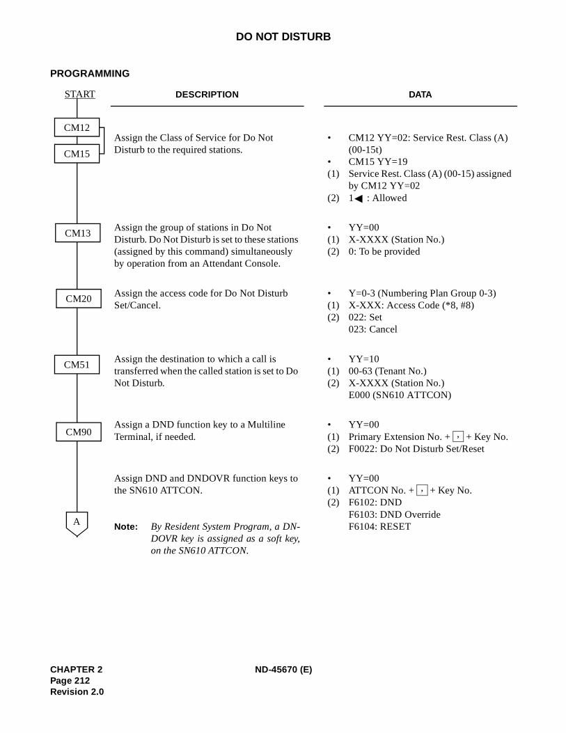
DO NOT DISTURB
PROGRAMMING
DESCRIPTION DATA
Assign the Class of Service for Do Not Disturb to the required stations.
• CM12 YY=02: Service Rest. Class (A)(00-15t)
• CM15 YY=19(1) Service Rest. Class (A) (00-15) assigned
by CM12 YY=02(2) 1 : Allowed
Assign the group of stations in Do Not Disturb. Do Not Disturb is set to these stations (assigned by this command) simultaneously by operation from an Attendant Console.
• YY=00(1) X-XXXX (Station No.)(2) 0: To be provided
Assign the access code for Do Not Disturb Set/Cancel.
• Y=0-3 (Numbering Plan Group 0-3) (1) X-XXX: Access Code (*8, #8) (2) 022: Set
023: Cancel
Assign the destination to which a call is transferred when the called station is set to Do Not Disturb.
• YY=10 (1) 00-63 (Tenant No.) (2) X-XXXX (Station No.)
E000 (SN610 ATTCON)
Assign a DND function key to a Multiline Terminal, if needed.
• YY=00 (1) Primary Extension No. + + Key No. (2) F0022: Do Not Disturb Set/Reset
Assign DND and DNDOVR function keys to the SN610 ATTCON.
Note: By Resident System Program, a DN-DOVR key is assigned as a soft key,on the SN610 ATTCON.
• YY=00 (1) ATTCON No. + + Key No. (2) F6102: DND
F6103: DND OverrideF6104: RESET
CM12
CM15
CM20
CM51
A
CM90
START
CM13
,
,
CHAPTER 2 ND-45670 (E)Page 212Revision 2.0
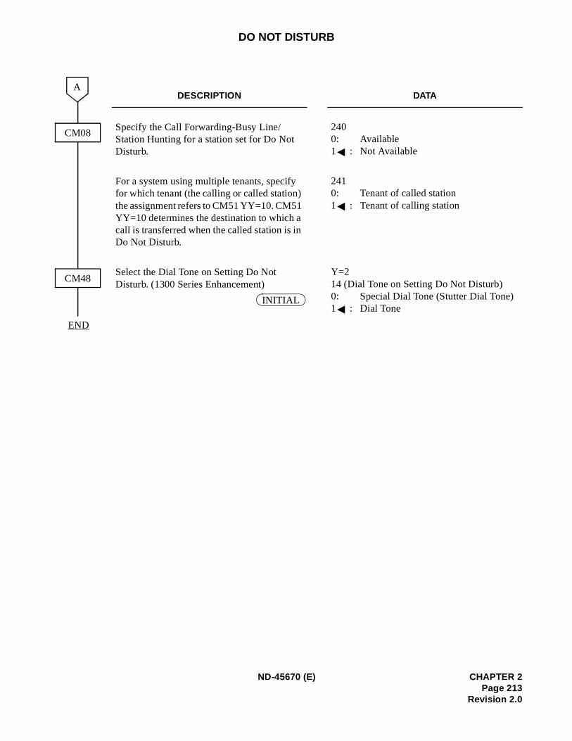
DO NOT DISTURB
DESCRIPTION DATA
Specify the Call Forwarding-Busy Line/Station Hunting for a station set for Do Not Disturb.
240 0: Available 1 : Not Available
For a system using multiple tenants, specify for which tenant (the calling or called station) the assignment refers to CM51 YY=10. CM51 YY=10 determines the destination to which a call is transferred when the called station is in Do Not Disturb.
241 0: Tenant of called station 1 : Tenant of calling station
Select the Dial Tone on Setting Do Not Disturb. (1300 Series Enhancement)
Y=2 14 (Dial Tone on Setting Do Not Disturb) 0: Special Dial Tone (Stutter Dial Tone)1 : Dial Tone
CM08
A
CM48
END
INITIAL
ND-45670 (E) CHAPTER 2Page 213
Revision 2.0
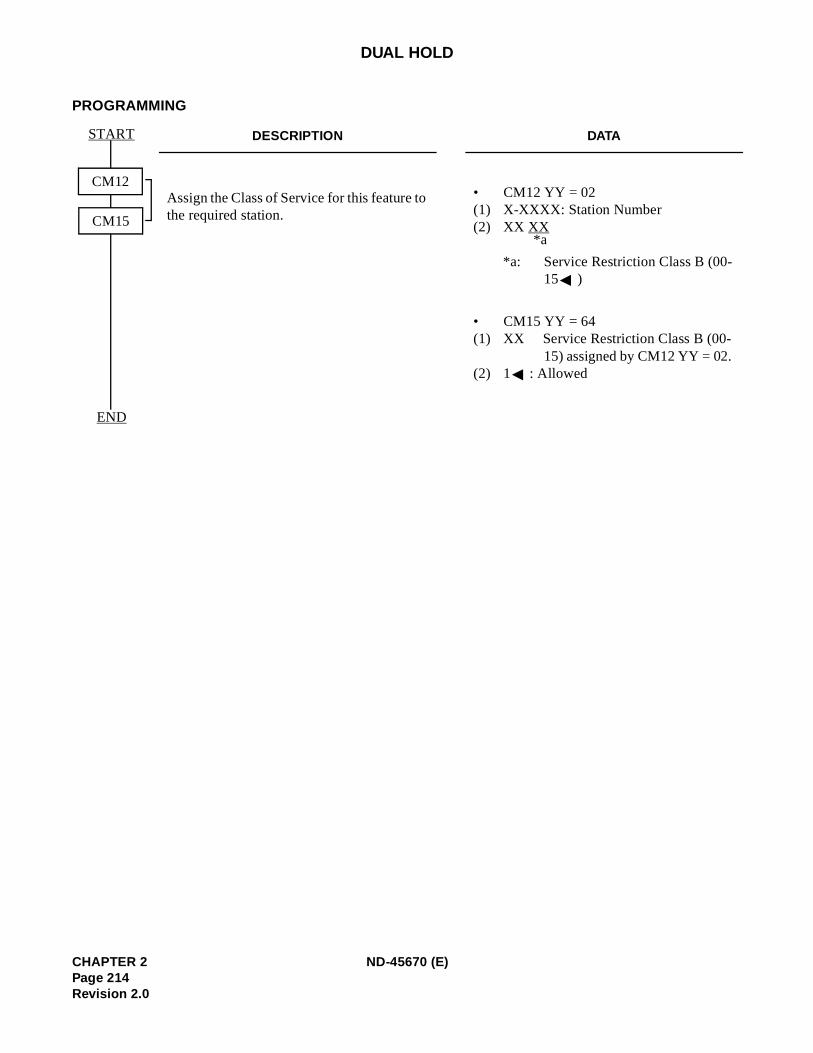
DUAL HOLD
PROGRAMMING
DESCRIPTION DATA
Assign the Class of Service for this feature to the required station.
• CM12 YY = 02 (1) X-XXXX: Station Number (2) XX XX
*a: Service Restriction Class B (00-15 )
• CM15 YY = 64 (1) XX Service Restriction Class B (00-
15) assigned by CM12 YY = 02. (2) 1 : Allowed
CM12
START
CM15
END
*a
CHAPTER 2 ND-45670 (E)Page 214Revision 2.0
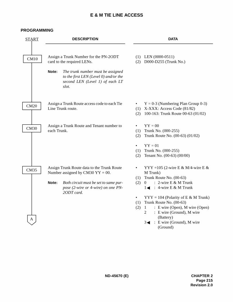
E & M TIE LINE ACCESS
PROGRAMMING
DESCRIPTION DATA
Assign a Trunk Number for the PN-2ODT card to the required LENs.
Note: The trunk number must be assignedto the first LEN (Level 0) and/or thesecond LEN (Level 1) of each LTslot.
(1) LEN (0000-0511) (2) D000-D255 (Trunk No.)
Assign a Trunk Route access code to each Tie Line Trunk route.
• Y = 0-3 (Numbering Plan Group 0-3) (1) X-XXX: Access Code (81/82) (2) 100-163: Trunk Route 00-63 (01/02)
Assign a Trunk Route and Tenant number to each Trunk.
• YY = 00 (1) Trunk No. (000-255) (2) Trunk Route No. (00-63) (01/02)
• YY = 01(1) Trunk No. (000-255) (2) Tenant No. (00-63) (00/00)
Assign Trunk Route data to the Trunk Route Number assigned by CM30 YY = 00.
Note: Both circuit must be set to same pur-pose (2-wire or 4-wire) on one PN-2ODT card.
• YYY =105 (2-wire E & M/4-wire E & M Trunk)
(1) Trunk Route No. (00-63) (2) 0 : 2-wire E & M Trunk
1 : 4-wire E & M Trunk
• YYY = 104 (Polarity of E & M Trunk) (1) Trunk Route No. (00-63) (2) 1 : E wire (Open), M wire (Open)
2 : E wire (Ground), M wire (Battery)
3 : E wire (Ground), M wire (Ground)
CM10
START
A
CM20
CM30
CM35
ND-45670 (E) CHAPTER 2Page 215
Revision 2.0
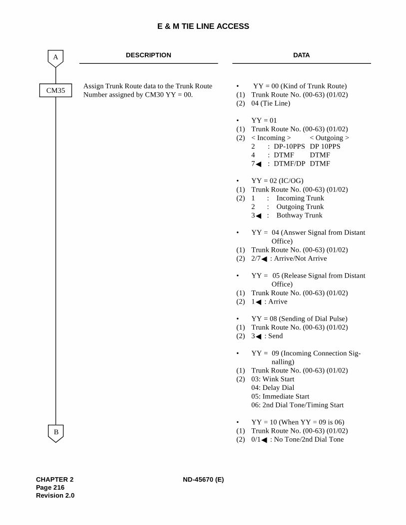
E & M TIE LINE ACCESS
DESCRIPTION DATA
Assign Trunk Route data to the Trunk Route Number assigned by CM30 YY = 00.
• YY = 00 (Kind of Trunk Route) (1) Trunk Route No. (00-63) (01/02) (2) 04 (Tie Line)
• YY = 01(1) Trunk Route No. (00-63) (01/02) (2) < Incoming > < Outgoing >
2 : DP-10PPS DP 10PPS 4 : DTMF DTMF
7 : DTMF/DP DTMF
• YY = 02 (IC/OG) (1) Trunk Route No. (00-63) (01/02) (2) 1 : Incoming Trunk
2 : Outgoing Trunk 3 : Bothway Trunk
• YY = 04 (Answer Signal from Distant Office)
(1) Trunk Route No. (00-63) (01/02) (2) 2/7 : Arrive/Not Arrive
• YY = 05 (Release Signal from Distant Office)
(1) Trunk Route No. (00-63) (01/02) (2) 1 : Arrive
• YY = 08 (Sending of Dial Pulse) (1) Trunk Route No. (00-63) (01/02) (2) 3 : Send
• YY = 09 (Incoming Connection Sig-nalling)
(1) Trunk Route No. (00-63) (01/02) (2) 03: Wink Start
04: Delay Dial 05: Immediate Start 06: 2nd Dial Tone/Timing Start
• YY = 10 (When YY = 09 is 06) (1) Trunk Route No. (00-63) (01/02) (2) 0/1 : No Tone/2nd Dial Tone
CM35
B
A
CHAPTER 2 ND-45670 (E)Page 216Revision 2.0
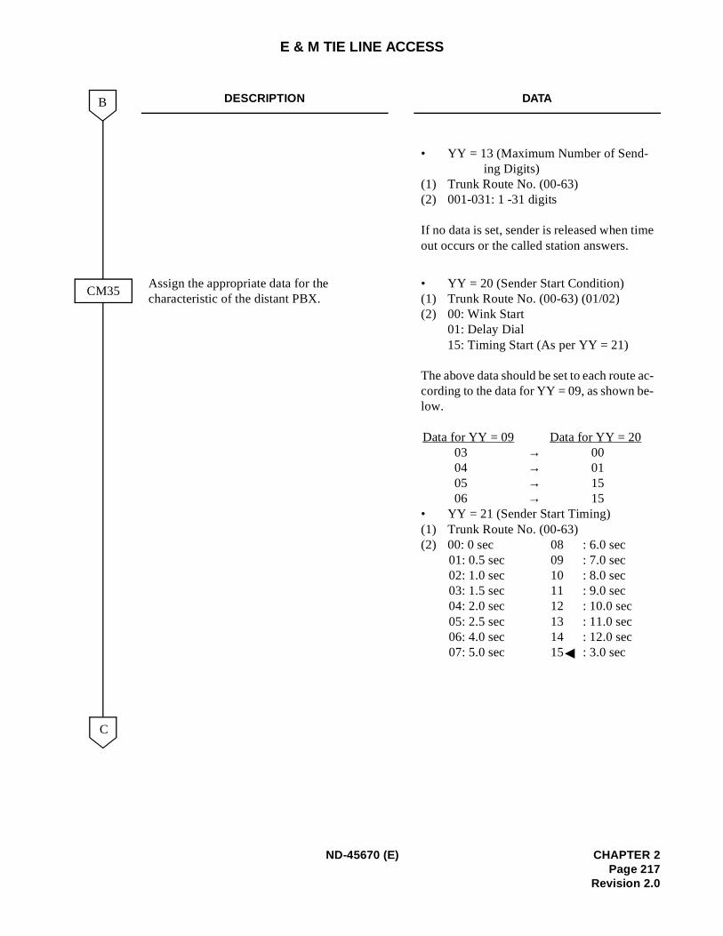
e
c--
E & M TIE LINE ACCESS
DESCRIPTION DATA
• YY = 13 (Maximum Number of Send-ing Digits)
(1) Trunk Route No. (00-63) (2) 001-031: 1 -31 digits
If no data is set, sender is released when timout occurs or the called station answers.
Assign the appropriate data for the characteristic of the distant PBX.
• YY = 20 (Sender Start Condition) (1) Trunk Route No. (00-63) (01/02) (2) 00: Wink Start
01: Delay Dial 15: Timing Start (As per YY = 21)
The above data should be set to each route acording to the data for YY = 09, as shown below.
Data for YY = 09 Data for YY = 2003 → 00 04 → 0105 → 1506 → 15
• YY = 21 (Sender Start Timing) (1) Trunk Route No. (00-63) (2) 00: 0 sec 08 : 6.0 sec
01: 0.5 sec 09 : 7.0 sec02: 1.0 sec 10 : 8.0 sec 03: 1.5 sec 11 : 9.0 sec 04: 2.0 sec 12 : 10.0 sec 05: 2.5 sec 13 : 11.0 sec06: 4.0 sec 14 : 12.0 sec 07: 5.0 sec 15 : 3.0 sec
CM35
C
B
ND-45670 (E) CHAPTER 2Page 217
Revision 2.0
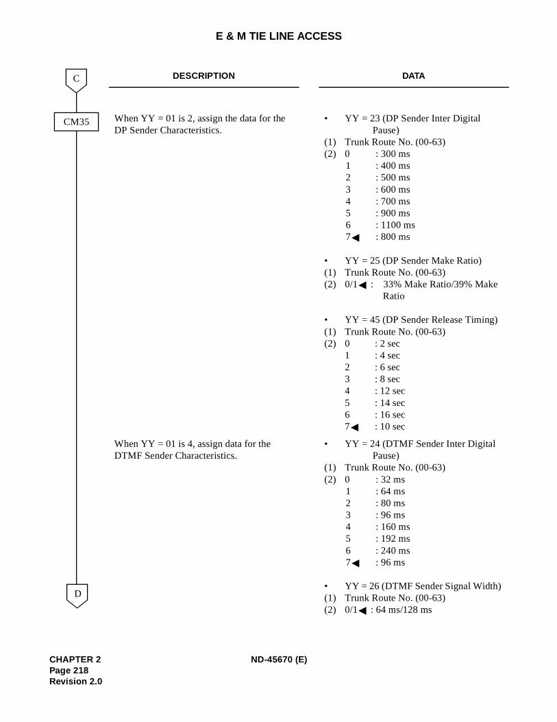
E & M TIE LINE ACCESS
DESCRIPTION DATA
When YY = 01 is 2, assign the data for the DP Sender Characteristics.
• YY = 23 (DP Sender Inter Digital Pause)
(1) Trunk Route No. (00-63) (2) 0 : 300 ms
1 : 400 ms 2 : 500 ms 3 : 600 ms 4 : 700 ms 5 : 900 ms 6 : 1100 ms 7 : 800 ms
• YY = 25 (DP Sender Make Ratio) (1) Trunk Route No. (00-63) (2) 0/1 : 33% Make Ratio/39% Make
Ratio
• YY = 45 (DP Sender Release Timing) (1) Trunk Route No. (00-63) (2) 0 : 2 sec
1 : 4 sec2 : 6 sec3 : 8 sec4 : 12 sec5 : 14 sec6 : 16 sec7 : 10 sec
When YY = 01 is 4, assign data for the DTMF Sender Characteristics.
• YY = 24 (DTMF Sender Inter Digital Pause)
(1) Trunk Route No. (00-63) (2) 0 : 32 ms
1 : 64 ms 2 : 80 ms 3 : 96 ms 4 : 160 ms 5 : 192 ms6 : 240 ms7 : 96 ms
• YY = 26 (DTMF Sender Signal Width) (1) Trunk Route No. (00-63) (2) 0/1 : 64 ms/128 ms
CM35
D
C
CHAPTER 2 ND-45670 (E)Page 218Revision 2.0

E & M TIE LINE ACCESS
DESCRIPTION DATA
• YY = 46 (DTMF Sender Release Tim-ing)
(1) Trunk Route No. (00-63) (2) 0 : 2 sec
1 : 4 sec 2 : 6 sec 3 : 8 sec4 : 12 sec 5 : 14 sec 6 : 16 sec7 : 10 sec
Specify the desired Station Ringing Cadence and Multiline Terminal Tone Ringer.
• YY = 33 (Ringing Cadence) (1) Trunk Route No. (00-63) (2) 2 : 1 sec ON, 2 sec OFF
3 : 2 sec ON, 4 sec OFF
To make this data assignment effectiveenter the data “1” for CM08-180
• YY = 34 (Multiline Terminal Tone Ringer)
(1) Trunk Route No. (00-63) (2) 0 : 1024+1285×16 (Hz)
1 : 480+606×8 (Hz) 2 : 600+700 (Hz) 3 : 480+606×16 (Hz)
CM35
E
D
ND-45670 (E) CHAPTER 2Page 219
Revision 2.0
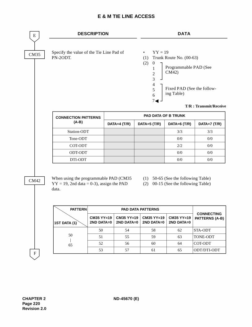
E & M TIE LINE ACCESS
DESCRIPTION DATA
Specify the value of the Tie Line Pad of PN-2ODT.
• YY = 19(1) Trunk Route No. (00-63) (2) 0
1 234 5 6 7
When using the programmable PAD (CM35 YY = 19, 2nd data = 0-3), assign the PAD data.
(1) 50-65 (See the following Table) (2) 00-15 (See the following Table)
CM35
F
E
CM42
T/R : Transmit/Receive
CONNECTION PATTERNS(A-B)
PAD DATA OF B TRUNK
DATA=4 (T/R) DATA=5 (T/R) DATA=6 (T/R) DATA=7 (T/R)
Station-ODT 3/3 3/3
Tone-ODT 0/0 0/0
COT-ODT 2/2 0/0
ODT-ODT 0/0 0/0
DTI-ODT 0/0 0/0
Programmable PAD (See CM42)
Fixed PAD (See the follow-ing Table)
PATTERN
1ST DATA (1)
PAD DATA PATTERNSCONNECTING
PATTERNS (A-B)CM35 YY=192ND DATA=0
CM35 YY=192ND DATA=0
CM35 YY=192ND DATA=0
CM35 YY=192ND DATA=0
50|
65
50 54 58 62 STA-ODT
51 55 59 63 TONE-ODT
52 56 60 64 COT-ODT
53 57 61 65 ODT/DTI-ODT
CHAPTER 2 ND-45670 (E)Page 220Revision 2.0
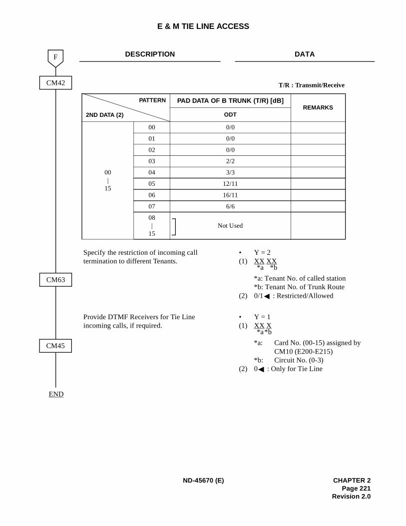
E & M TIE LINE ACCESS
DESCRIPTION DATA
Specify the restriction of incoming call termination to different Tenants.
• Y = 2 (1) XX XX
*a: Tenant No. of called station*b: Tenant No. of Trunk Route
(2) 0/1 : Restricted/Allowed
Provide DTMF Receivers for Tie Line incoming calls, if required.
• Y = 1(1) XX X
*a: Card No. (00-15) assigned by CM10 (E200-E215)
*b: Circuit No. (0-3) (2) 0 : Only for Tie Line
CM42
F
END
CM63
CM45
T/R : Transmit/Receive
PATTERN
2ND DATA (2)
PAD DATA OF B TRUNK (T/R) [dB]REMARKS
ODT
00|
15
00 0/0
01 0/0
02 0/0
03 2/2
04 3/3
05 12/11
06 16/11
07 6/6
08|
15Not Used
*b*a
*b*a
ND-45670 (E) CHAPTER 2Page 221
Revision 2.0
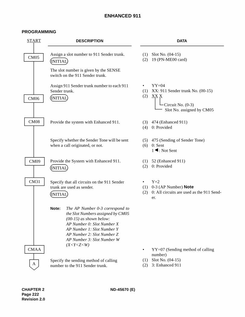
ENHANCED 911
PROGRAMMING
DESCRIPTION DATA
Assign a slot number to 911 Sender trunk.
The slot number is given by the SENSE switch on the 911 Sender trunk.
Assign 911 Sender trunk number to each 911 Sender trunk.
(1) Slot No. (04-15)(2) 19 (PN-ME00 card)
• YY=04(1) XX: 911 Sender trunk No. (00-15)(2) XX X
Provide the system with Enhanced 911. (3) 474 (Enhanced 911)(4) 0: Provided
Specify whether the Sender Tone will be sent when a call originated, or not.
Provide the System with Enhanced 911.
Specify that all circuits on the 911 Sender trunk are used as sender.
Note: The AP Number 0-3 correspond tothe Slot Numbers assigned by CM05(00-15) as shown below:AP Number 0: Slot Number XAP Number 1: Slot Number YAP Number 2: Slot Number ZAP Number 3: Slot Number W(X<Y<Z<W)
Specify the sending method of calling number to the 911 Sender trunk.
(5) 475 (Sending of Sender Tone)(6) 0: Sent
1 : Not Sent
(1) 52 (Enhanced 911)(2) 0: Provided
• Y=2(1) 0-3 (AP Number) Note(2) 0: All circuits are used as the 911 Send-
er.
• YY=07 (Sending method of calling number)
(1) Slot No. (04-15)(2) 3: Enhanced 911
CM05
CM06
START
A
CM08
CM09
CM31
CMAA
INITIAL
INITIAL
Circuit No. (0-3)Slot No. assigned by CM05
INITIAL
INITIAL
CHAPTER 2 ND-45670 (E)Page 222Revision 2.0
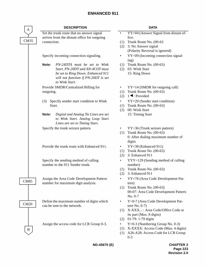
ENHANCED 911
DESCRIPTION DATA
Set the trunk route that no answer signal arrives from the distant office for outgoing connection.
• YY=04 (Answer Signal from distant of-fice.
(1) Trunk Route No. (00-63(2) 3: No Answer signal
(Polarity Reversal is ignored)Specify incoming connection signaling.
Note: PN-24DTA must be set to WinkStart. PN-20DT and AN-4COT mustbe set to Ring Down. Enhanced 911will not function if PN-20DT is setto Wink Start.
• YY=09 (Incoming connection signal-ing)
(1) Trunk Route No. (00-63)(2) 03: Wink Start
15: Ring Down
Provide SMDR/Centralized Billing for outgoing.
• YY=14 (SMDR for outgoing call)(1) Trunk Route No. (00-63)(2) 1 : Provided
(3) Specify sender start condition to Wink Start.
Note: Digital and Analog Tie Lines are setto Wink Start. Analog Loop StartLines are set to Timing Start.
• YY=20 (Sender start condition)(1) Trunk Route No. (00-63)(2) 00: Wink Start
15: Timing Start
Specify the trunk seizure pattern. • YY=36 (Trunk seizure pattern)(1) Trunk Route No. (00-63)
0: After dialing maximum number of digits
Provide the trunk route with Enhanced 911. • YY=38 (Enhanced 911)(1) Trunk Route No. (00-63)(2) 3: Enhanced 911
Specify the sending method of calling number to the 911 Sender trunk.
• YYY=129 (Sending method of calling number)
(1) Trunk Route No. (00-63)(2) 3: Enhanced 911
Assign the Area Code Development Pattern number for maximum digit analysis.
• YY=76 (Area Code Development Pat-tern)
(1) Trunk Route No. (00-63)00-07: Area Code Development PatternNo. 0-7
Define the maximum number of digits which can be sent to the network.
• Y=0-7 (Area Code Development Pat-tern No. 0-7)
(1) X-XXX... : Area Code/Office Code orits part (Max. 8 digits)
(2) 01-79: 1-79 digitsAssign the access code for LCR Group 0-3. • Y=0-3 (Numbering Group No. 0-3)
(1) X-XXXX: Access Code (Max. 4 digits)(1) A26-A28: Access Code for LCR Group
0-3
CM35
CM85
B
A
CM20
ND-45670 (E) CHAPTER 2Page 223
Revision 2.0
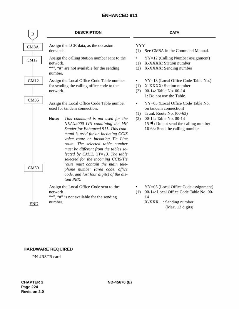
ENHANCED 911
DESCRIPTION DATA
Assign the LCR data, as the occasion demands.
YYY(1) See CM8A in the Command Manual.
Assign the calling station number sent to the network.“*”, “#” are not available for the sending number.
• YY=12 (Calling Number assignment)(1) X-XXXX: Station number(2) X-XXXX: Sending number
Assign the Local Office Code Table number for sending the calling office code to the network.
• YY=13 (Local Office Code Table No.)(1) X-XXXX: Station number(2) 00-14: Table No. 00-14
1: Do not use the Table.
Assign the Local Office Code Table number used for tandem connection.
Note: This command is not used for theNEAX2000 IVS containing the MFSender for Enhanced 911. This com-mand is used for an incoming CCISvoice route or incoming Tie Lineroute. The selected table numbermust be different from the tables se-lected by CM12, YY=13. The tableselected for the incoming CCIS/Tieroute must contain the main tele-phone number (area code, officecode, and last four digits) of the dis-tant PBX.
• YY=03 (Local Office Code Table No. on tandem connection)
(1) Trunk Route No. (00-63)(2) 00-14: Table No. 00-14
15 : Do not send the calling number16-63: Send the calling number
Assign the Local Office Code sent to the network.“*”, “#” is not available for the sending number.
• YY=05 (Local Office Code assignment)(1) 00-14: Local Office Code Table No. 00-
14X-XXX... : Sending number
(Max. 12 digits)
HARDWARE REQUIRED
PN-4RSTB card
CM8A
CM35
B
CM50
CM12
CM12
END
CHAPTER 2 ND-45670 (E)Page 224Revision 2.0
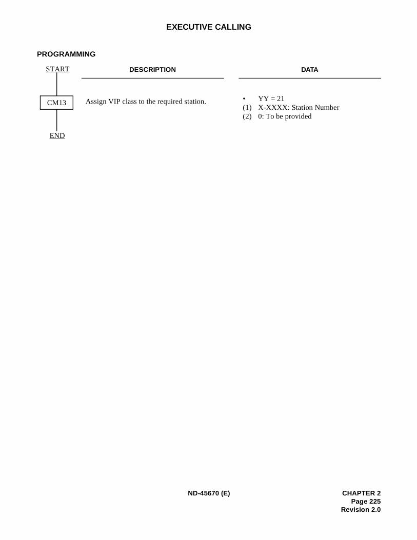
EXECUTIVE CALLING
PROGRAMMING
DESCRIPTION DATA
Assign VIP class to the required station. • YY = 21(1) X-XXXX: Station Number (2) 0: To be provided
CM13
START
END
ND-45670 (E) CHAPTER 2Page 225
Revision 2.0
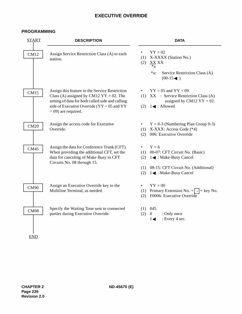
EXECUTIVE OVERRIDE
PROGRAMMING
DESCRIPTION DATA
Assign Service Restriction Class (A) to each station.
• YY = 02(1) X-XXXX (Station No.) (2) XX XX
*a: Service Restriction Class (A)
(00-15 )
Assign this feature to the Service Restriction Class (A) assigned by CM12 YY = 02. The setting of data for both called side and calling side of Executive Override (YY = 05 and YY = 09) are required.
• YY = 05 and YY = 09(1) XX : Service Restriction Class (A)
assigned by CM12 YY = 02.(2) 1 : Allowed
Assign the access code for Executive Override.
• Y = 0-3 (Numbering Plan Group 0-3) (1) X-XXX: Access Code (*4) (2) 006: Executive Override
Assign the data for Conference Trunk (CFT). When providing the additional CFT, set the data for canceling of Make Busy to CFT Circuits No. 08 through 15.
• Y = 6(1) 00-07: CFT Circuit No. (Basic) (2) 1 : Make-Busy Cancel
(1) 08-15: CFT Circuit No. (Additional) (2) 1 : Make-Busy Cancel
Assign an Executive Override key to the Multiline Terminal, as needed.
• YY = 00 (1) Primary Extension No. + + key No. (2) F0006: Executive Override
Specify the Waiting Tone sent to connected parties during Executive Override.
(1) 045 (2) 0 : Only once
1 : Every 4 sec.
CM12
START
END
CM15
CM20
CM45
CM90
CM08
*a
,
CHAPTER 2 ND-45670 (E)Page 226Revision 2.0
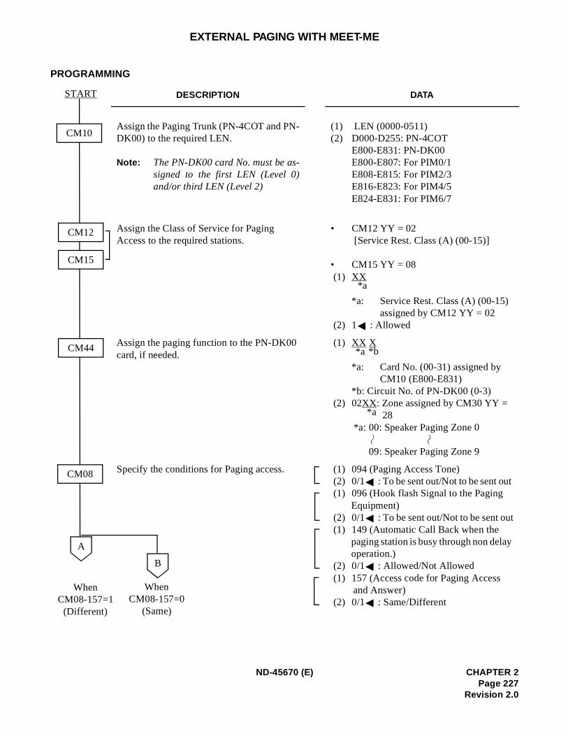
t
EXTERNAL PAGING WITH MEET-ME
PROGRAMMING
DESCRIPTION DATA
Assign the Paging Trunk (PN-4COT and PN-DK00) to the required LEN.
Note: The PN-DK00 card No. must be as-signed to the first LEN (Level 0)and/or third LEN (Level 2)
(1) LEN (0000-0511) (2) D000-D255: PN-4COT
E800-E831: PN-DK00 E800-E807: For PIM0/1 E808-E815: For PIM2/3E816-E823: For PIM4/5E824-E831: For PIM6/7
Assign the Class of Service for Paging Access to the required stations.
• CM12 YY = 02 [Service Rest. Class (A) (00-15)]
• CM15 YY = 08 (1) XX
*a: Service Rest. Class (A) (00-15) assigned by CM12 YY = 02
(2) 1 : Allowed
Assign the paging function to the PN-DK00 card, if needed.
(1) XX X
*a: Card No. (00-31) assigned by CM10 (E800-E831)
*b: Circuit No. of PN-DK00 (0-3) (2) 02XX: Zone assigned by CM30 YY =
28 *a: 00: Speaker Paging Zone 0
09: Speaker Paging Zone 9
Specify the conditions for Paging access. (1) 094 (Paging Access Tone) (2) 0/1 : To be sent out/Not to be sent out (1) 096 (Hook flash Signal to the Paging
Equipment) (2) 0/1 : To be sent out/Not to be sent ou (1) 149 (Automatic Call Back when the
paging station is busy through non delayoperation.)
(2) 0/1 : Allowed/Not Allowed (1) 157 (Access code for Paging Access
and Answer) (2) 0/1 : Same/Different
CM10
START
CM44
CM08
CM12
CM15
A
*a
*a *b
*a
B
WhenCM08-157=0
(Same)
WhenCM08-157=1(Different)
ND-45670 (E) CHAPTER 2Page 227
Revision 2.0
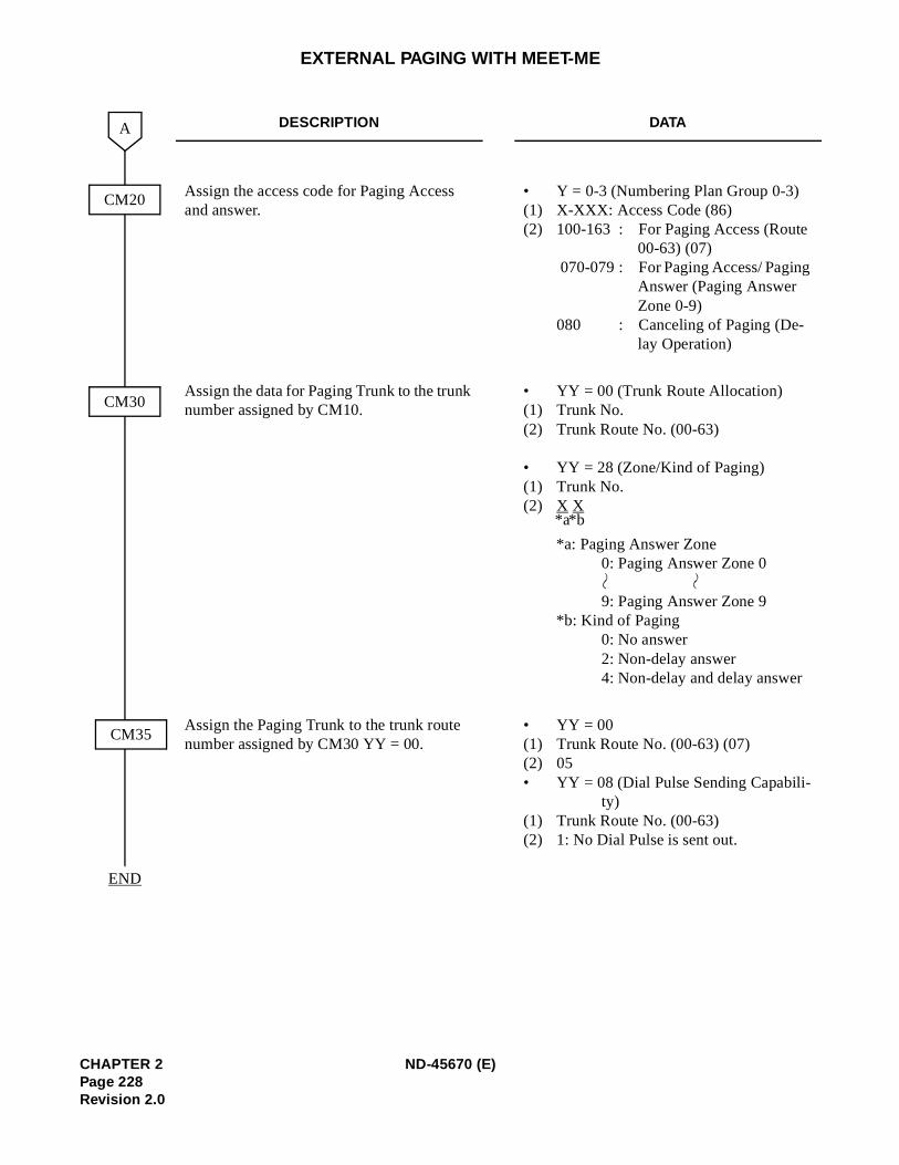
EXTERNAL PAGING WITH MEET-ME
DESCRIPTION DATA
Assign the access code for Paging Access and answer.
• Y = 0-3 (Numbering Plan Group 0-3) (1) X-XXX: Access Code (86) (2) 100-163 : For Paging Access (Route
00-63) (07) 070-079 : For Paging Access/ Paging
Answer (Paging Answer Zone 0-9)
080 : Canceling of Paging (De-lay Operation)
Assign the data for Paging Trunk to the trunk number assigned by CM10.
• YY = 00 (Trunk Route Allocation) (1) Trunk No. (2) Trunk Route No. (00-63)
• YY = 28 (Zone/Kind of Paging) (1) Trunk No. (2) X X
*a: Paging Answer Zone0: Paging Answer Zone 0
9: Paging Answer Zone 9 *b: Kind of Paging 0: No answer 2: Non-delay answer 4: Non-delay and delay answer
Assign the Paging Trunk to the trunk route number assigned by CM30 YY = 00.
• YY = 00 (1) Trunk Route No. (00-63) (07) (2) 05• YY = 08 (Dial Pulse Sending Capabili-
ty) (1) Trunk Route No. (00-63) (2) 1: No Dial Pulse is sent out.
END
CM20
A
CM30
CM35
*b*a
CHAPTER 2 ND-45670 (E)Page 228Revision 2.0
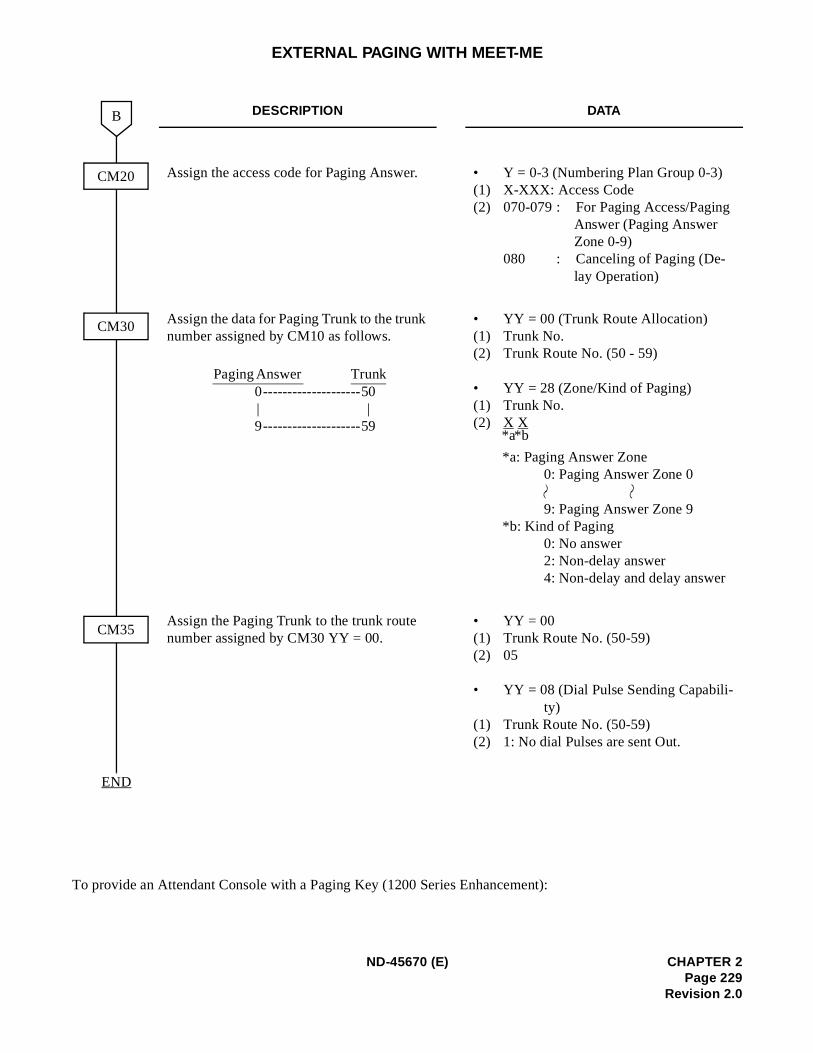
3)
EXTERNAL PAGING WITH MEET-ME
To provide an Attendant Console with a Paging Key (1200 Series Enhancement):
DESCRIPTION DATA
Assign the access code for Paging Answer. • Y = 0-3 (Numbering Plan Group 0-(1) X-XXX: Access Code(2) 070-079 : For Paging Access/Paging
Answer (Paging Answer Zone 0-9)
080 : Canceling of Paging (De-lay Operation)
Assign the data for Paging Trunk to the trunk number assigned by CM10 as follows.
• YY = 00 (Trunk Route Allocation)(1) Trunk No.(2) Trunk Route No. (50 - 59)
• YY = 28 (Zone/Kind of Paging) (1) Trunk No. (2) X X
*a: Paging Answer Zone0: Paging Answer Zone 0
9: Paging Answer Zone 9
*b: Kind of Paging0: No answer2: Non-delay answer 4: Non-delay and delay answer
Assign the Paging Trunk to the trunk route number assigned by CM30 YY = 00.
• YY = 00 (1) Trunk Route No. (50-59) (2) 05
• YY = 08 (Dial Pulse Sending Capabili-ty)
(1) Trunk Route No. (50-59)(2) 1: No dial Pulses are sent Out.
END
CM20
B
CM30
CM35
Paging Answer Trunk0 --------------------50 | |9--------------------59
*b*a
ND-45670 (E) CHAPTER 2Page 229
Revision 2.0
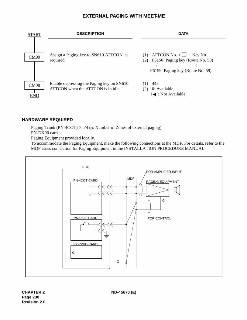
EXTERNAL PAGING WITH MEET-ME
HARDWARE REQUIRED
Paging Trunk (PN-4COT) × n/4 (n: Number of Zones of external paging) PN-DK00 cardPaging Equipment provided locally.To accommodate the Paging Equipment, make the following connections at the MDF. For details, refer to the MDF cross connection for Paging Equipment in the INSTALLATION PROCEDURE MANUAL.
DESCRIPTION DATA
Assign a Paging key to SN610 ATTCON, as required.
(1) ATTCON No. + + Key No.(2) F6150: Paging key (Route No. 50)
F6159: Paging key (Route No. 59)
Enable depressing the Paging key on SN610 ATTCON when the ATTCON is in idle.
(1) 445(2) 0: Available
1 : Not Available
START
END
CM90
CM08
,
PBX
PN-4COT CARD
PN-DK00 CARD
PZ-PW86 CARD
G
G
MDF
FOR AMPLIFIER INPUT
PAGING EQUIPMENT
G
FOR CONTROL
CHAPTER 2 ND-45670 (E)Page 230Revision 2.0
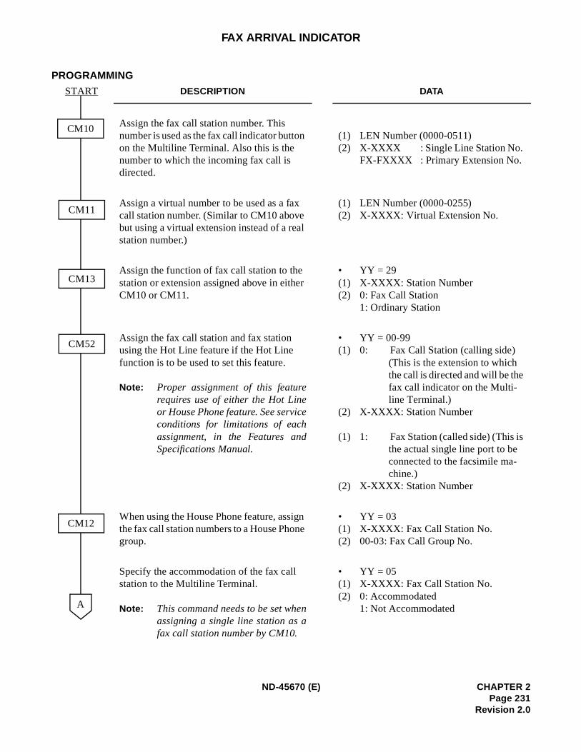
FAX ARRIVAL INDICATOR
PROGRAMMING
DESCRIPTION DATA
Assign the fax call station number. This number is used as the fax call indicator button on the Multiline Terminal. Also this is the number to which the incoming fax call is directed.
(1) LEN Number (0000-0511) (2) X-XXXX : Single Line Station No.
FX-FXXXX : Primary Extension No.
Assign a virtual number to be used as a fax call station number. (Similar to CM10 above but using a virtual extension instead of a real station number.)
(1) LEN Number (0000-0255) (2) X-XXXX: Virtual Extension No.
Assign the function of fax call station to the station or extension assigned above in either CM10 or CM11.
• YY = 29(1) X-XXXX: Station Number (2) 0: Fax Call Station
1: Ordinary Station
Assign the fax call station and fax station using the Hot Line feature if the Hot Line function is to be used to set this feature.
Note: Proper assignment of this featurerequires use of either the Hot Lineor House Phone feature. See serviceconditions for limitations of eachassignment, in the Features andSpecifications Manual.
• YY = 00-99 (1) 0: Fax Call Station (calling side)
(This is the extension to which the call is directed and will be the fax call indicator on the Multi-line Terminal.)
(2) X-XXXX: Station Number
(1) 1: Fax Station (called side) (This is the actual single line port to be connected to the facsimile ma-chine.)
(2) X-XXXX: Station Number
When using the House Phone feature, assign the fax call station numbers to a House Phone group.
• YY = 03(1) X-XXXX: Fax Call Station No. (2) 00-03: Fax Call Group No.
Specify the accommodation of the fax call station to the Multiline Terminal.
Note: This command needs to be set whenassigning a single line station as afax call station number by CM10.
• YY = 05(1) X-XXXX: Fax Call Station No. (2) 0: Accommodated
1: Not Accommodated
START
CM10
A
CM11
CM13
CM52
CM12
ND-45670 (E) CHAPTER 2Page 231
Revision 2.0
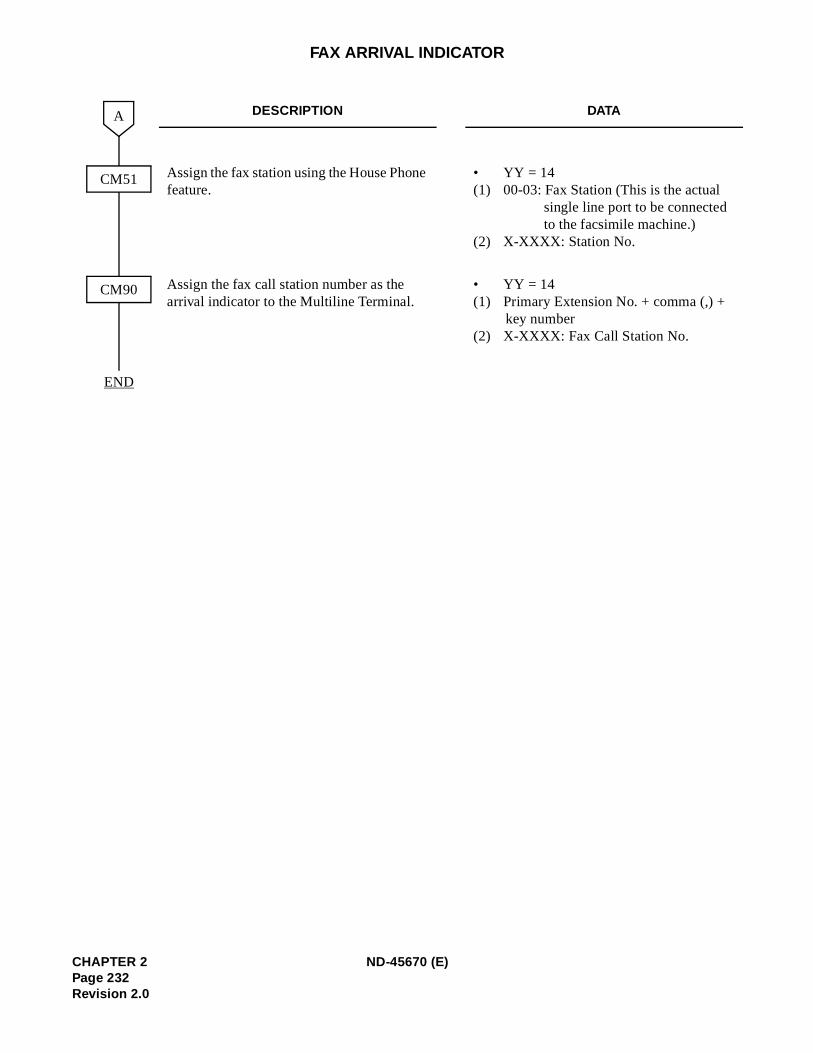
FAX ARRIVAL INDICATOR
DESCRIPTION DATA
Assign the fax station using the House Phone feature.
• YY = 14 (1) 00-03: Fax Station (This is the actual
single line port to be connected to the facsimile machine.)
(2) X-XXXX: Station No.
Assign the fax call station number as the arrival indicator to the Multiline Terminal.
• YY = 14(1) Primary Extension No. + comma (,) +
key number(2) X-XXXX: Fax Call Station No.
END
CM51
A
CM90
CHAPTER 2 ND-45670 (E)Page 232Revision 2.0
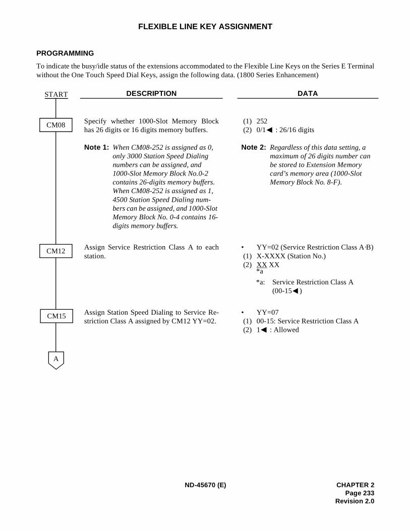
erminal
FLEXIBLE LINE KEY ASSIGNMENT
PROGRAMMING
To indicate the busy/idle status of the extensions accommodated to the Flexible Line Keys on the Series E Twithout the One Touch Speed Dial Keys, assign the following data. (1800 Series Enhancement)
DESCRIPTION DATA
Specify whether 1000-Slot Memory Blockhas 26 digits or 16 digits memory buffers.
Note 1: When CM08-252 is assigned as 0, only 3000 Station Speed Dialing numbers can be assigned, and 1000-Slot Memory Block No.0-2 contains 26-digits memory buffers. When CM08-252 is assigned as 1, 4500 Station Speed Dialing num-bers can be assigned, and 1000-Slot Memory Block No. 0-4 contains 16-digits memory buffers.
(1) 252 (2) 0/1 : 26/16 digits
Note 2: Regardless of this data setting, a maximum of 26 digits number canbe stored to Extension Memory card’s memory area (1000-Slot Memory Block No. 8-F).
Assign Service Restriction Class A to eachstation.
• YY=02 (Service Restriction Class A·B) (1) X-XXXX (Station No.) (2) XX XX
*a: Service Restriction Class A (00-15 )
Assign Station Speed Dialing to Service Re-striction Class A assigned by CM12 YY=02.
• YY=07(1) 00-15: Service Restriction Class A(2) 1 : Allowed
START
CM08
CM12
A
CM15
*a
ND-45670 (E) CHAPTER 2Page 233
Revision 2.0
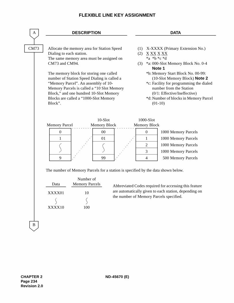
FLEXIBLE LINE KEY ASSIGNMENT
DESCRIPTION DATA
Allocate the memory area for Station Speed Dialing to each station. The same memory area must be assigned on CM73 and CM94.
The memory block for storing one called number of Station Speed Dialing is called a “Memory Parcel”. An assembly of 10-Memory Parcels is called a “10 Slot Memory Block,” and one hundred 10-Slot Memory Blocks are called a “1000-Slot Memory Block”.
(1) X-XXXX (Primary Extension No.)(2) X XX X XX
*a *b *c *d (3) *a: 000-Slot Memory Block No. 0-4
Note 1 *b: Memory Start Block No. 00-99:
(10-Slot Memory Block) Note 2*c: Facility for programming the dialed
number from the Station(0/1: Effective/Ineffective)
*d: Number of blocks in Memory Parcel(01-10)
CM73
B
A
The number of Memory Parcels for a station is specified by the data shown below.
DataNumber of
Memory Parcels Abbreviated Codes required for accessing this featureare automatically given to each station, depending onthe number of Memory Parcels specified.
XXXX01 10
XXXX10 100
0
4
1
2
3
1000-SlotMemory Block
0
9
1
Memory Parcel
00
99
01
10-SlotMemory Block
1000 Memory Parcels
1000 Memory Parcels
1000 Memory Parcels
1000 Memory Parcels
500 Memory Parcels
CHAPTER 2 ND-45670 (E)Page 234Revision 2.0
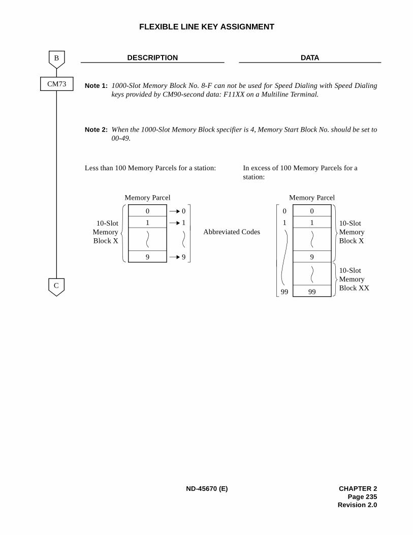
ialing
set to
FLEXIBLE LINE KEY ASSIGNMENT
DESCRIPTION DATA
Note 1: 1000-Slot Memory Block No. 8-F can not be used for Speed Dialing with Speed Dkeys provided by CM90-second data: F11XX on a Multiline Terminal.
Note 2: When the 1000-Slot Memory Block specifier is 4, Memory Start Block No. should be00-49.
Less than 100 Memory Parcels for a station: In excess of 100 Memory Parcels for a station:
C
B
CM73
0
9
1
Memory Parcel
10-SlotMemoryBlock X
Memory Parcel
0
9
1
0
9
1 10-Slot Memory Block X
99
10-Slot Memory Block XX
0
1
99
Abbreviated Codes
ND-45670 (E) CHAPTER 2Page 235
Revision 2.0
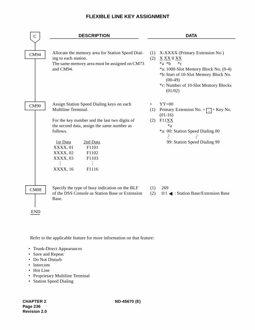
Base
FLEXIBLE LINE KEY ASSIGNMENT
Refer to the applicable feature for more information on that feature:
• Trunk-Direct Appearances • Save and Repeat• Do Not Disturb • Intercom • Hot Line • Proprietary Multiline Terminal • Station Speed Dialing
DESCRIPTION DATA
Allocate the memory area for Station Speed Dial-ing to each station. The same memory area must be assigned on CM73 and CM94.
(1) X-XXXX (Primary Extension No.)(2) X XX 0 XX
*a *b *c *a: 1000-Slot Memory Block No. (0-4) *b: Start of 10-Slot Memory Block No.
(00-49) *c: Number of 10-Slot Memory Blocks
(01/02)
Assign Station Speed Dialing keys on each Multiline Terminal.
For the key number and the last two digits of the second data, assign the same number as follows.
1st Data 2nd DataXXXX, 01 F1101XXXX, 02 F1102XXXX, 03 F1103
XXXX, 16 F1116
• YY=00(1) Primary Extension No. + + Key No.
(01-16)(2) F11XX
*a *a: 00: Station Speed Dialing 00
99: Station Speed Dialing 99
Specify the type of busy indication on the BLF (1) 269of the DSS Console as Station Base or Extension (2) 0/1 : Station Base/Extension Base.
CM94
C
CM90
END
CM08
......
,
CHAPTER 2 ND-45670 (E)Page 236Revision 2.0
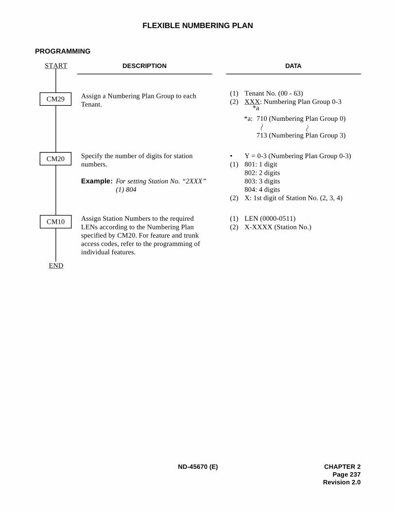
FLEXIBLE NUMBERING PLAN
PROGRAMMING
DESCRIPTION DATA
Assign a Numbering Plan Group to each Tenant.
(1) Tenant No. (00 - 63) (2) XXX: Numbering Plan Group 0-3
*a: 710 (Numbering Plan Group 0)
713 (Numbering Plan Group 3)
Specify the number of digits for station numbers.
Example: For setting Station No. “2XXX” (1) 804
• Y = 0-3 (Numbering Plan Group 0-3) (1) 801: 1 digit
802: 2 digits803: 3 digits804: 4 digits
(2) X: 1st digit of Station No. (2, 3, 4)
Assign Station Numbers to the required LENs according to the Numbering Plan specified by CM20. For feature and trunk access codes, refer to the programming of individual features.
(1) LEN (0000-0511) (2) X-XXXX (Station No.)
CM29
START
CM10
END
CM20
*a
ND-45670 (E) CHAPTER 2Page 237
Revision 2.0
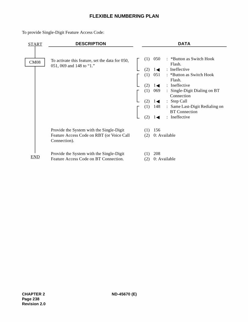
FLEXIBLE NUMBERING PLAN
To provide Single-Digit Feature Access Code:
DESCRIPTION DATA
To activate this feature, set the data for 050, 051, 069 and 148 to “1.”
(1) 050 : *Button as Switch Hook Flash.
(2) 1 : Ineffective (1) 051 : *Button as Switch Hook
Flash. (2) 1 : Ineffective (1) 069 : Single-Digit Dialing on BT
Connection (2) 1 : Step Call(1) 148 : Same Last-Digit Redialing on
BT Connection (2) 1 : Ineffective
Provide the System with the Single-Digit Feature Access Code on RBT (or Voice Call Connection).
(1) 156 (2) 0: Available
Provide the System with the Single-Digit Feature Access Code on BT Connection.
(1) 208 (2) 0: Available
CM08
START
END
CHAPTER 2 ND-45670 (E)Page 238Revision 2.0
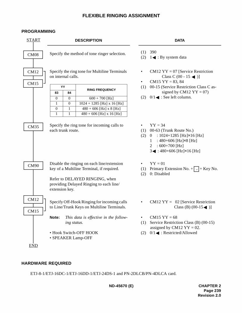
FLEXIBLE RINGING ASSIGNMENT
PROGRAMMING
HARDWARE REQUIRED
ETJ-8-1/ETJ-16DC-1/ETJ-16DD-1/ETJ-24DS-1 and PN-2DLCB/PN-4DLCA card.
DESCRIPTION DATA
Specify the method of tone ringer selection. (1) 390 (2) 1 : By system data
Specify the ring tone for Multiline Terminals on internal calls.
• CM12 YY = 07 [Service Restriction Class C (00 - 15 )]
• CM15 YY = 83, 84 (1) 00-15 (Service Restriction Class C as-
signed by CM12 YY = 07) (2) 0/1 : See left column.
Specify the ring tone for incoming calls to each trunk route.
• YY = 34(1) 00-63 (Trunk Route No.) (2) 0 : 1024+1285 [Hz]×16 [Hz]
1 : 480+606 [Hz]×8 [Hz] 2 : 600+700 [Hz]3 : 480+606 [Hz]×16 [Hz]
Disable the ringing on each line/extension key of a Multiline Terminal, if required.
Refer to DELAYED RINGING, when providing Delayed Ringing to each line/extension key.
• YY = 01(1) Primary Extension No. + + Key No. (2) 0: Disabled
Specify Off-Hook Ringing for incoming calls to Line/Trunk Keys on Multiline Terminals.
Note: This data is effective in the follow-ing status.
• Hook Switch-OFF HOOK • SPEAKER Lamp-OFF
• CM12 YY = 02 [Service Restriction Class (B) (00-15 )]
• CM15 YY = 68 (1) Service Restriction Class (B) (00-15)
assigned by CM12 YY = 02.(2) 0/1 : Restricted/Allowed
CM08
START
END
CM12
CM15
CM35
CM90
CM12
CM15
YYRING FREQUENCY
83 84
0 0 600 + 700 [Hz]1 0 1024 + 1285 [Hz] x 16 [Hz]0 1 480 + 606 [Hz] x 8 [Hz]1 1 480 + 606 [Hz] x 16 [Hz]
,
ND-45670 (E) CHAPTER 2Page 239
Revision 2.0
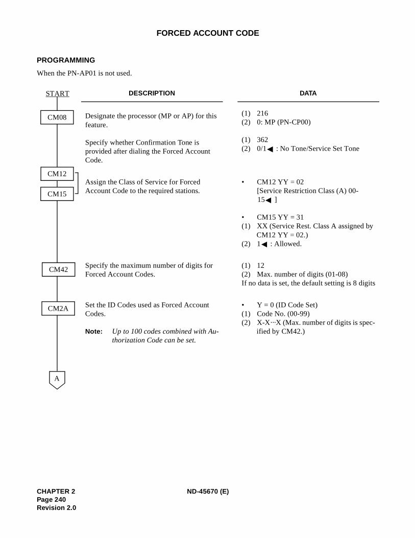
FORCED ACCOUNT CODE
PROGRAMMING
When the PN-AP01 is not used.
DESCRIPTION DATA
Designate the processor (MP or AP) for this feature.
Specify whether Confirmation Tone is provided after dialing the Forced Account Code.
(1) 216(2) 0: MP (PN-CP00)
(1) 362(2) 0/1 : No Tone/Service Set Tone
Assign the Class of Service for Forced Account Code to the required stations.
• CM12 YY = 02[Service Restriction Class (A) 00-15 ]
• CM15 YY = 31(1) XX (Service Rest. Class A assigned by
CM12 YY = 02.) (2) 1 : Allowed.
Specify the maximum number of digits for Forced Account Codes.
(1) 12(2) Max. number of digits (01-08) If no data is set, the default setting is 8 digits
Set the ID Codes used as Forced Account Codes.
Note: Up to 100 codes combined with Au-thorization Code can be set.
• Y = 0 (ID Code Set) (1) Code No. (00-99) (2) X-X···X (Max. number of digits is spec-
ified by CM42.)
A
START
CM42
CM2A
CM12
CM15
CM08
CHAPTER 2 ND-45670 (E)Page 240Revision 2.0
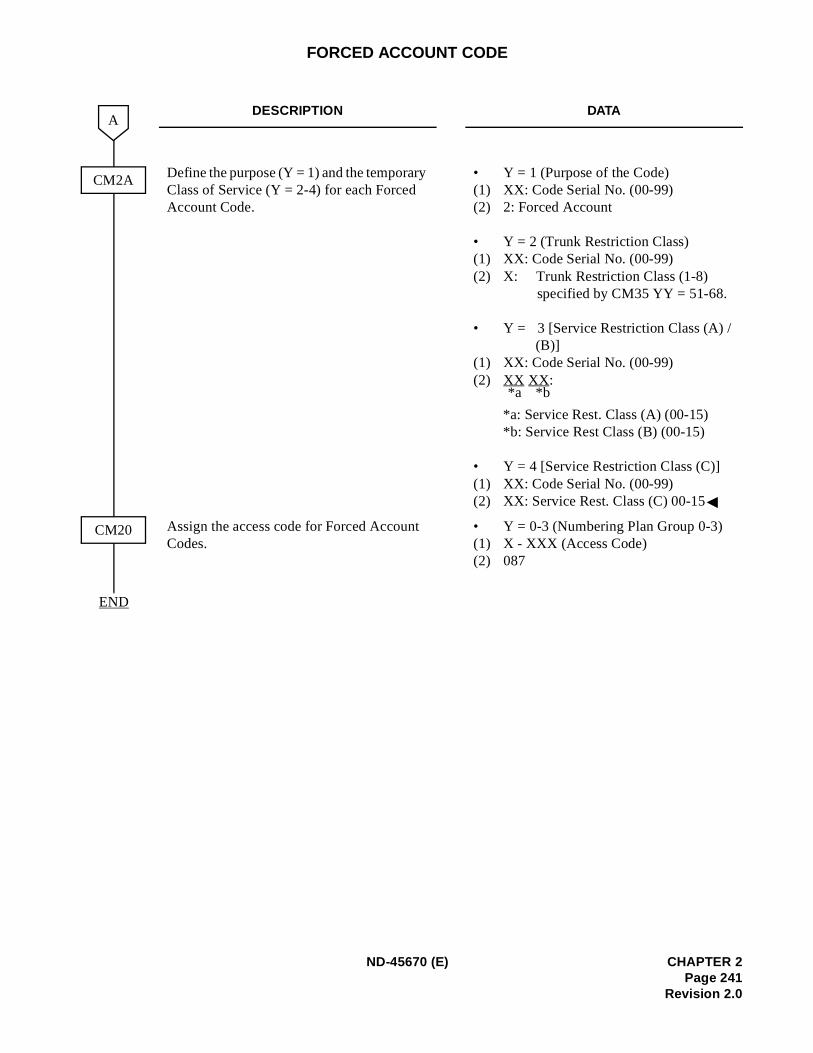
FORCED ACCOUNT CODE
DESCRIPTION DATA
Define the purpose (Y = 1) and the temporary Class of Service (Y = 2-4) for each Forced Account Code.
• Y = 1 (Purpose of the Code) (1) XX: Code Serial No. (00-99) (2) 2: Forced Account
• Y = 2 (Trunk Restriction Class) (1) XX: Code Serial No. (00-99) (2) X: Trunk Restriction Class (1-8)
specified by CM35 YY = 51-68.
• Y = 3 [Service Restriction Class (A) / (B)]
(1) XX: Code Serial No. (00-99) (2) XX XX:
*a: Service Rest. Class (A) (00-15) *b: Service Rest Class (B) (00-15)
• Y = 4 [Service Restriction Class (C)] (1) XX: Code Serial No. (00-99) (2) XX: Service Rest. Class (C) 00-15
Assign the access code for Forced Account Codes.
• Y = 0-3 (Numbering Plan Group 0-3) (1) X - XXX (Access Code) (2) 087
END
CM2A
A
CM20
*b*a
ND-45670 (E) CHAPTER 2Page 241
Revision 2.0
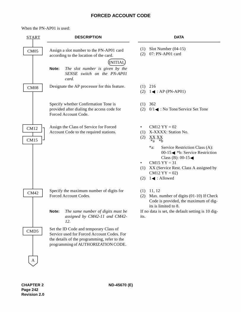
-
FORCED ACCOUNT CODE
When the PN-AP01 is used:
DESCRIPTION DATA
Assign a slot number to the PN-AP01 card according to the location of the card.
Note: The slot number is given by theSENSE switch on the PN-AP01card.
(1) Slot Number (04-15) (2) 07: PN-AP01 card
Designate the AP processor for this feature. (1) 216 (2) 1 : AP (PN-AP01)
Specify whether Confirmation Tone is provided after dialing the access code for Forced Account Code.
(1) 362 (2) 0/1 : No Tone/Service Set Tone
Assign the Class of Service for Forced Account Code to the required stations.
• CM12 YY = 02(1) X-XXXX: Station No. (2) XX XX
*a: Service Restriction Class (A): 00-15 *b: Service Restriction Class (B): 00-15
• CM15 YY = 31 (1) XX (Service Rest. Class A assigned by
CM12 YY = 02) (2) 1 : Allowed
Specify the maximum number of digits for Forced Account Codes.
Note: The same number of digits must beassigned by CM42-11 and CM42-12.
(1) 11, 12(2) Max. number of digits (01-10) If Check
Code is provided, the maximum of dig-its is limited to 8.
If no data is set, the default setting is 10 digits.
Set the ID Code and temporary Class of Service used for Forced Account Codes. For the details of the programming, refer to the programming of AUTHORIZATION CODE.
START
CM05
CM12
CM15
CM08
CM42
CMD5
A
INITIAL
*b*a
CHAPTER 2 ND-45670 (E)Page 242Revision 2.0
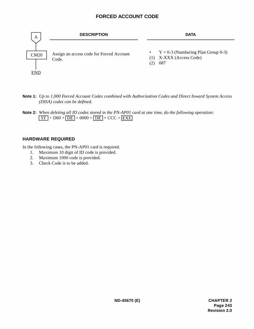
Access
FORCED ACCOUNT CODE
Note 1: Up to 1,000 Forced Account Codes combined with Authorization Codes and Direct Inward System (DISA) codes can be defined.
Note 2: When deleting all ID codes stored in the PN-AP01 card at one time, do the following operation: + D60 + + 0000 + + CCC +
HARDWARE REQUIRED
In the following cases, the PN-AP01 card is required.1. Maximum 10 digit of ID code is provided.2. Maximum 1000 code is provided.3. Check Code is to be added.
DESCRIPTION DATA
Assign an access code for Forced Account Code.
• Y = 0-3 (Numbering Plan Group 0-3) (1) X-XXX (Access Code) (2) 087
CM20
END
A
ST DE DE EXE
ND-45670 (E) CHAPTER 2Page 243
Revision 2.0
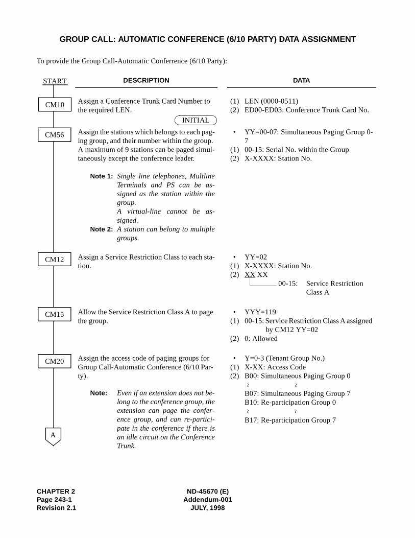
CHAPTER 2 ND-45670 (E)Page 243-1 Addendum-001Revision 2.1 JULY, 1998
GROUP CALL: AUTOMATIC CONFERENCE (6/10 PARTY) DATA ASSIGNMENT
To provide the Group Call-Automatic Conferrence (6/10 Party):
DESCRIPTION DATA
Assign a Conference Trunk Card Number to the required LEN.
(1)(2)
LEN (0000-0511)ED00-ED03: Conference Trunk Card No.
Assign the stations which belongs to each pag-ing group, and their number within the group. A maximum of 9 stations can be paged simul-taneously except the conference leader.
Note 1: Single line telephones, MultlineTerminals and PS can be as-signed as the station within thegroup.A virtual-line cannot be as-signed.
Note 2: A station can belong to multiplegroups.
•
(1)(2)
YY=00-07: Simultaneous Paging Group 0-700-15: Serial No. within the GroupX-XXXX: Station No.
Assign a Service Restriction Class to each sta-tion.
•(1)(2)
YY=02X-XXXX: Station No.XX XX
00-15: Service Restriction Class A
Allow the Service Restriction Class A to page the group.
•(1)
(2)
YYY=11900-15: Service Restriction Class A assigned
by CM12 YY=020: Allowed
Assign the access code of paging groups for Group Call-Automatic Conference (6/10 Par-ty).
Note: Even if an extension does not be-long to the conference group, theextension can page the confer-ence group, and can re-partici-pate in the conference if there isan idle circuit on the ConferenceTrunk.
•(1)(2)
Y=0-3 (Tenant Group No.)X-XX: Access CodeB00: Simultaneous Paging Group 0
B07: Simultaneous Paging Group 7B10: Re-participation Group 0
B17: Re-participation Group 7
START
CM56
CM12
CM20
CM15
A
CM10
INITIAL
~~
~~
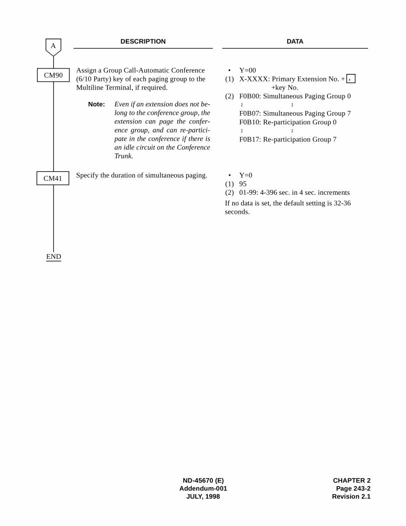
ND-45670 (E) CHAPTER 2Addendum-001 Page 243-2
JULY, 1998 Revision 2.1
DESCRIPTION DATA
Assign a Group Call-Automatic Conference (6/10 Party) key of each paging group to the Multiline Terminal, if required.
Note: Even if an extension does not be-long to the conference group, theextension can page the confer-ence group, and can re-partici-pate in the conference if there isan idle circuit on the ConferenceTrunk.
•(1)
(2)
Y=00X-XXXX: Primary Extension No. +
+key No.F0B00: Simultaneous Paging Group 0
F0B07: Simultaneous Paging Group 7F0B10: Re-participation Group 0
F0B17: Re-participation Group 7
Specify the duration of simultaneous paging. •(1)(2)
Y=09501-99: 4-396 sec. in 4 sec. increments
If no data is set, the default setting is 32-36 seconds.
CM41
A
END
CM90 ,
~~
~~
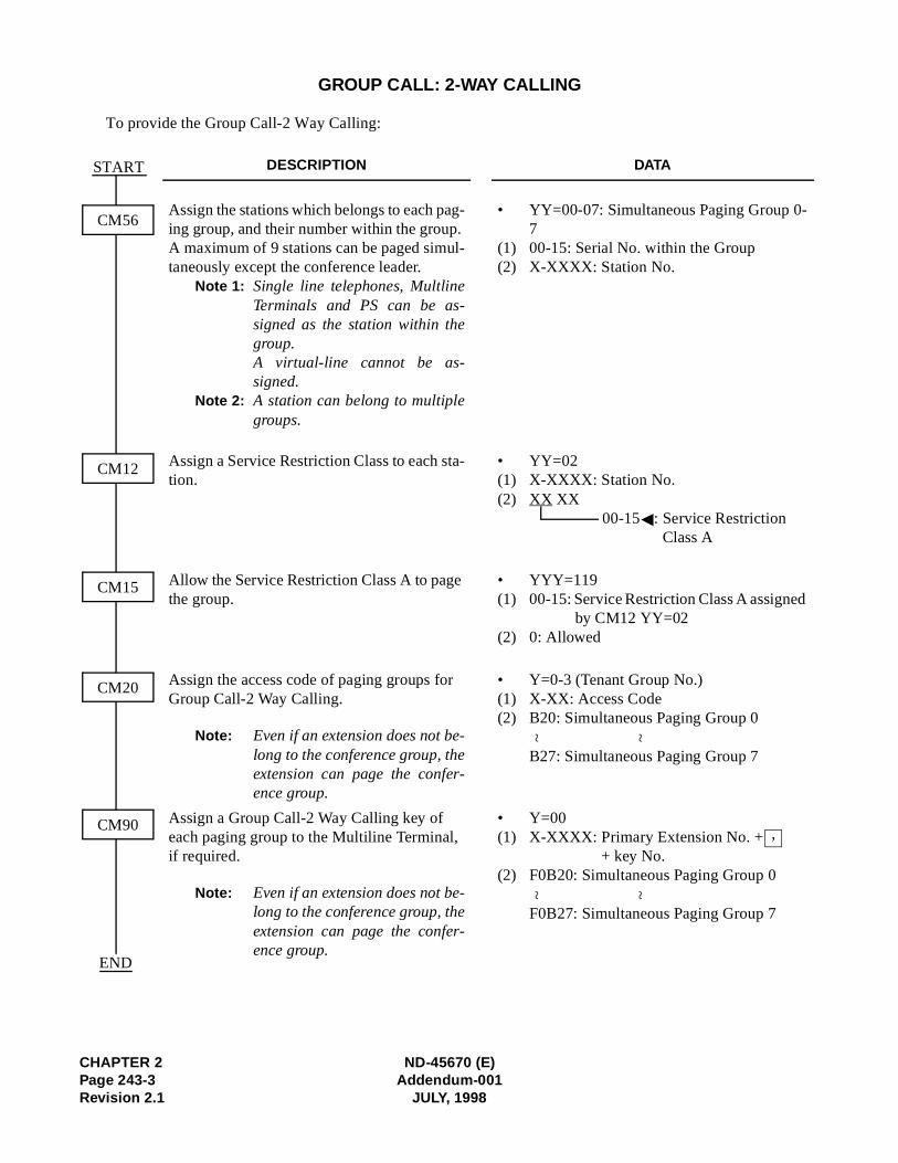
CHAPTER 2 ND-45670 (E)Page 243-3 Addendum-001Revision 2.1 JULY, 1998
GROUP CALL: 2-WAY CALLING
To provide the Group Call-2 Way Calling:
DESCRIPTION DATA
Assign the stations which belongs to each pag-ing group, and their number within the group. A maximum of 9 stations can be paged simul-taneously except the conference leader.
Note 1: Single line telephones, MultlineTerminals and PS can be as-signed as the station within thegroup.A virtual-line cannot be as-signed.
Note 2: A station can belong to multiplegroups.
•
(1)(2)
YY=00-07: Simultaneous Paging Group 0-700-15: Serial No. within the GroupX-XXXX: Station No.
Assign a Service Restriction Class to each sta-tion.
•(1)(2)
YY=02X-XXXX: Station No.XX XX
00-15 : Service Restriction Class A
Allow the Service Restriction Class A to page the group.
•(1)
(2)
YYY=11900-15: Service Restriction Class A assigned
by CM12 YY=020: Allowed
Assign the access code of paging groups for Group Call-2 Way Calling.
Note: Even if an extension does not be-long to the conference group, theextension can page the confer-ence group.
•(1)(2)
Y=0-3 (Tenant Group No.)X-XX: Access CodeB20: Simultaneous Paging Group 0
B27: Simultaneous Paging Group 7
Assign a Group Call-2 Way Calling key of each paging group to the Multiline Terminal, if required.
Note: Even if an extension does not be-long to the conference group, theextension can page the confer-ence group.
•(1)
(2)
Y=00X-XXXX: Primary Extension No. +
+ key No.F0B20: Simultaneous Paging Group 0
F0B27: Simultaneous Paging Group 7
START
CM56
CM12
CM20
CM15
END
CM90
~~
,
~~

ND-45670 (E) CHAPTER 2Addendum-001 Page 243-4
JULY, 1998 Revision 2.1
This page is for your notes.
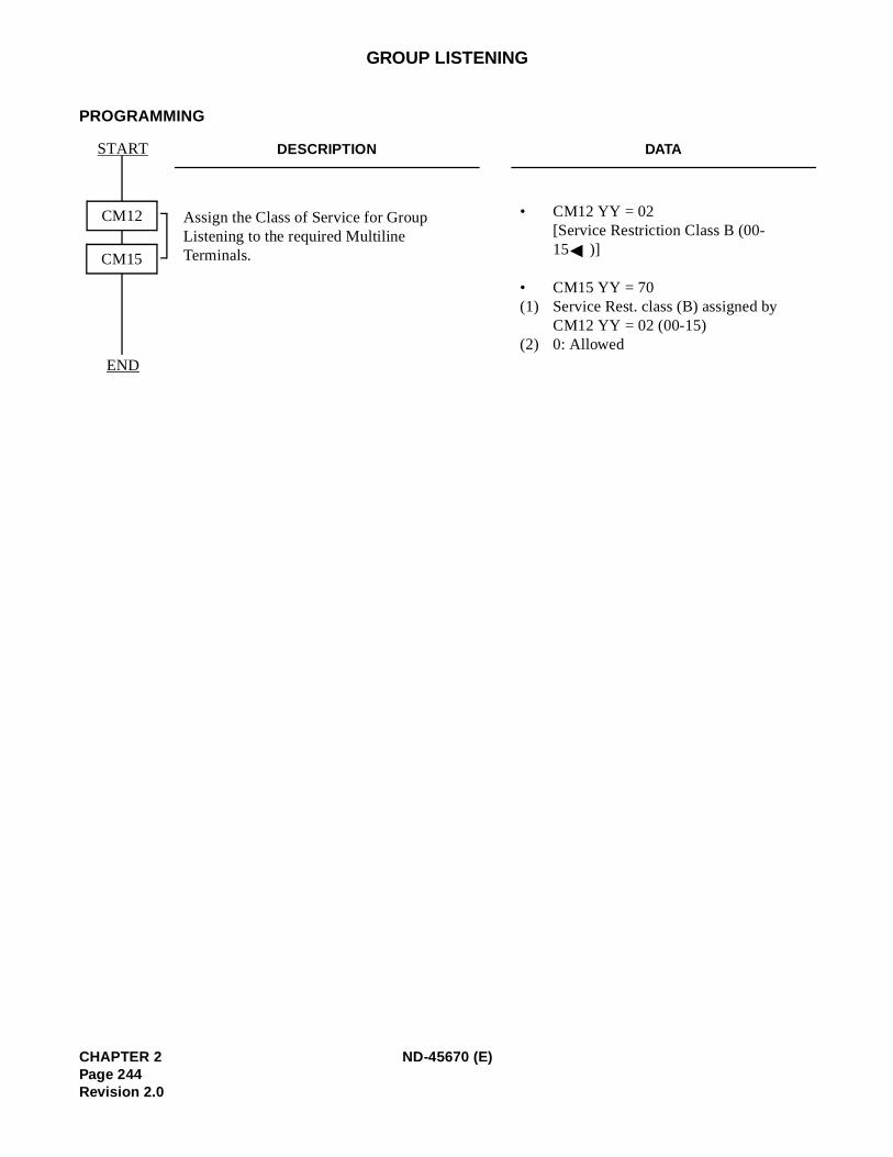
GROUP LISTENING
PROGRAMMING
DESCRIPTION DATA
Assign the Class of Service for Group Listening to the required Multiline Terminals.
• CM12 YY = 02[Service Restriction Class B (00-15 )]
• CM15 YY = 70(1) Service Rest. class (B) assigned by
CM12 YY = 02 (00-15) (2) 0: Allowed
START
END
CM12
CM15
CHAPTER 2 ND-45670 (E)Page 244Revision 2.0
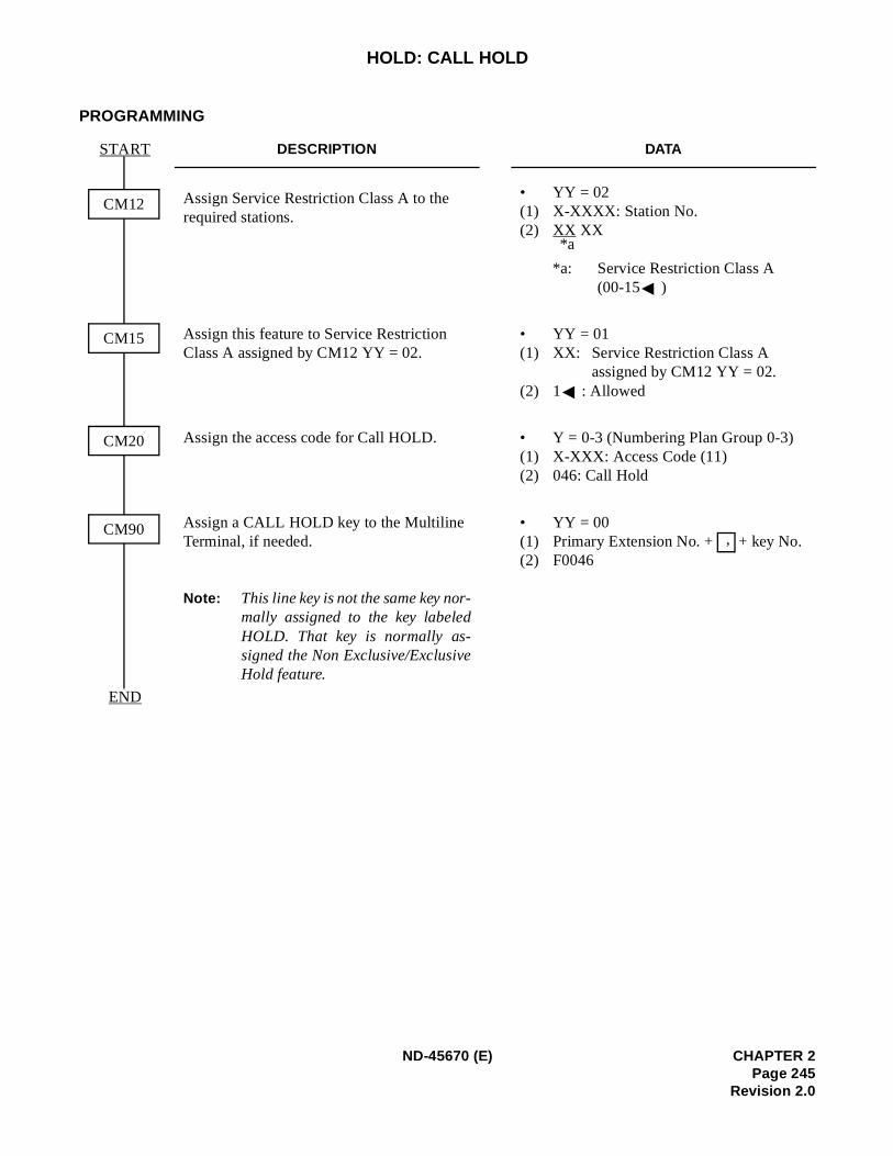
)
HOLD: CALL HOLD
PROGRAMMING
DESCRIPTION DATA
Assign Service Restriction Class A to the required stations.
• YY = 02(1) X-XXXX: Station No.(2) XX XX
*a: Service Restriction Class A (00-15 )
Assign this feature to Service Restriction Class A assigned by CM12 YY = 02.
• YY = 01(1) XX: Service Restriction Class A
assigned by CM12 YY = 02. (2) 1 : Allowed
Assign the access code for Call HOLD. • Y = 0-3 (Numbering Plan Group 0-3(1) X-XXX: Access Code (11) (2) 046: Call Hold
Assign a CALL HOLD key to the Multiline Terminal, if needed.
Note: This line key is not the same key nor-mally assigned to the key labeledHOLD. That key is normally as-signed the Non Exclusive/ExclusiveHold feature.
• YY = 00 (1) Primary Extension No. + + key No. (2) F0046
START
END
CM12
CM15
CM20
CM90
*a
,
ND-45670 (E) CHAPTER 2Page 245
Revision 2.0
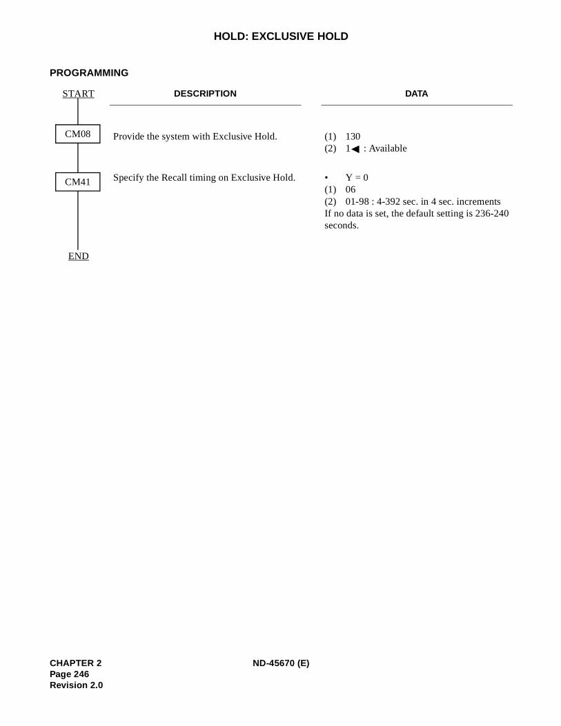
0
HOLD: EXCLUSIVE HOLD
PROGRAMMING
DESCRIPTION DATA
Provide the system with Exclusive Hold. (1) 130 (2) 1 : Available
Specify the Recall timing on Exclusive Hold. • Y = 0 (1) 06(2) 01-98 : 4-392 sec. in 4 sec. incrementsIf no data is set, the default setting is 236-24seconds.
START
END
CM08
CM41
CHAPTER 2 ND-45670 (E)Page 246Revision 2.0
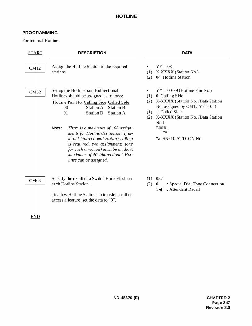
HOTLINE
PROGRAMMING
For internal Hotline:
DESCRIPTION DATA
Assign the Hotline Station to the required stations.
• YY = 03(1) X-XXXX (Station No.) (2) 04: Hotline Station
Set up the Hotline pair. Bidirectional Hotlines should be assigned as follows:
Note: There is a maximum of 100 assign-ments for Hotline destination. If in-ternal bidirectional Hotline callingis required, two assignments (onefor each direction) must be made. Amaximum of 50 bidirectional Hot-lines can be assigned.
• YY = 00-99 (Hotline Pair No.) (1) 0: Calling Side (2) X-XXXX (Station No. /Data Station
No. assigned by CM12 YY = 03) (1) 1: Called Side(2) X-XXXX (Station No. /Data Station
No.) E00X
*a: SN610 ATTCON No.
Specify the result of a Switch Hook Flash on each Hotline Station.
To allow Hotline Stations to transfer a call or access a feature, set the data to “0”.
(1) 057 (2) 0 : Special Dial Tone Connection
1 : Attendant Recall
START
END
CM12
CM08
CM52
Hotline Pair No. Calling Side Called Side00 Station A Station B01 Station B Station A
*a
ND-45670 (E) CHAPTER 2Page 247
Revision 2.0
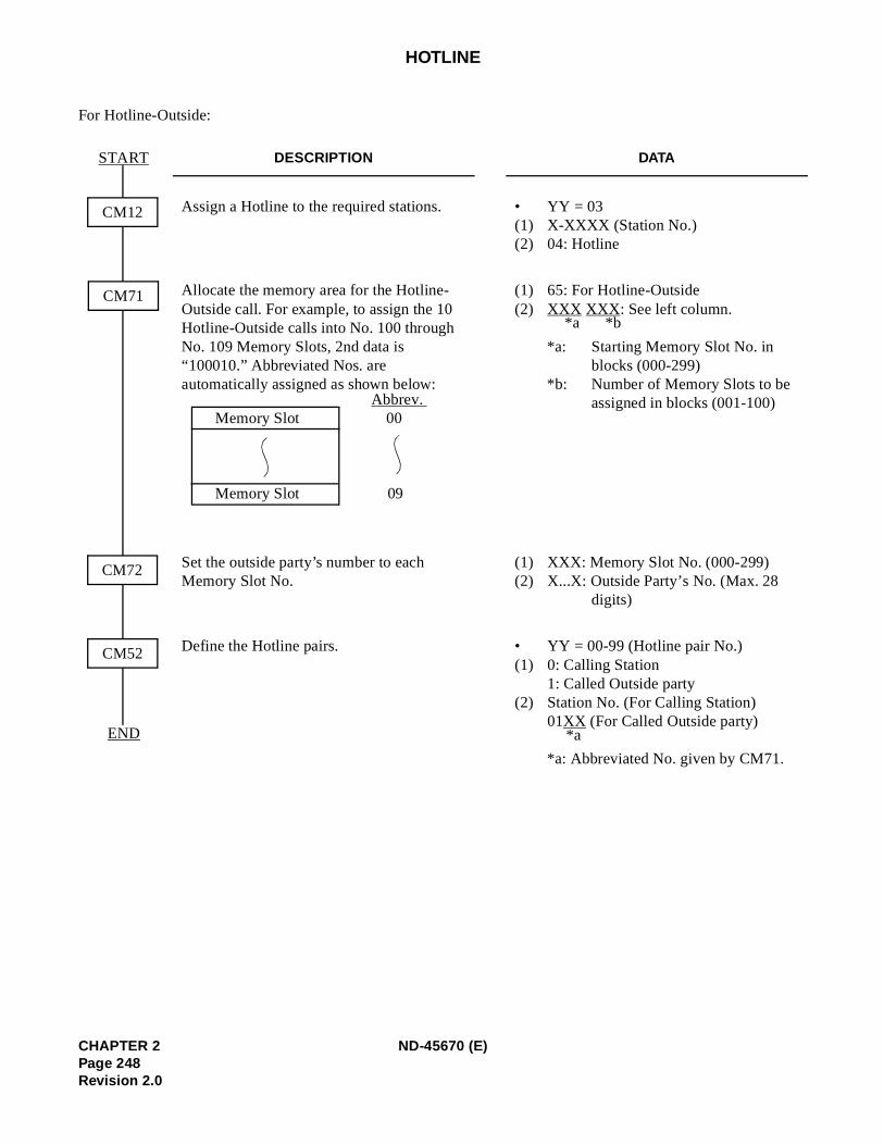
HOTLINE
For Hotline-Outside:
DESCRIPTION DATA
Assign a Hotline to the required stations. • YY = 03(1) X-XXXX (Station No.) (2) 04: Hotline
Allocate the memory area for the Hotline-Outside call. For example, to assign the 10 Hotline-Outside calls into No. 100 through No. 109 Memory Slots, 2nd data is “100010.” Abbreviated Nos. are automatically assigned as shown below:
(1) 65: For Hotline-Outside(2) XXX XXX : See left column.
*a: Starting Memory Slot No. in blocks (000-299)
*b: Number of Memory Slots to be assigned in blocks (001-100)
Set the outside party’s number to each Memory Slot No.
(1) XXX: Memory Slot No. (000-299) (2) X...X: Outside Party’s No. (Max. 28
digits)
Define the Hotline pairs. • YY = 00-99 (Hotline pair No.) (1) 0: Calling Station
1: Called Outside party (2) Station No. (For Calling Station)
01XX (For Called Outside party)
*a: Abbreviated No. given by CM71.
START
END
CM12
CM52
CM71
CM72
Abbrev. Memory Slot 00
Memory Slot 09
*b*a
*a
CHAPTER 2 ND-45670 (E)Page 248Revision 2.0
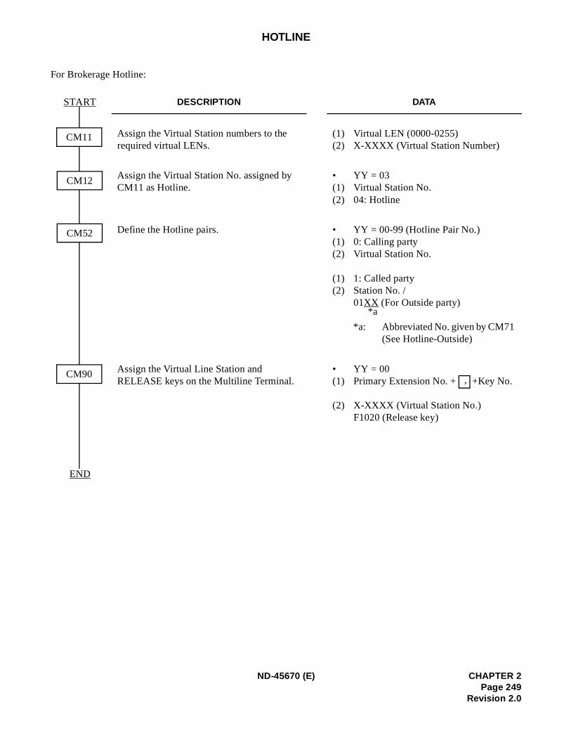
HOTLINE
For Brokerage Hotline:
DESCRIPTION DATA
Assign the Virtual Station numbers to the required virtual LENs.
(1) Virtual LEN (0000-0255) (2) X-XXXX (Virtual Station Number)
Assign the Virtual Station No. assigned by CM11 as Hotline.
• YY = 03(1) Virtual Station No. (2) 04: Hotline
Define the Hotline pairs. • YY = 00-99 (Hotline Pair No.) (1) 0: Calling party (2) Virtual Station No.
(1) 1: Called party(2) Station No. /
01XX (For Outside party)
*a: Abbreviated No. given by CM71 (See Hotline-Outside)
Assign the Virtual Line Station and RELEASE keys on the Multiline Terminal.
• YY = 00 (1) Primary Extension No. + +Key No.
(2) X-XXXX (Virtual Station No.)F1020 (Release key)
START
END
CM11
CM90
CM52
CM12
*a
,
ND-45670 (E) CHAPTER 2Page 249
Revision 2.0
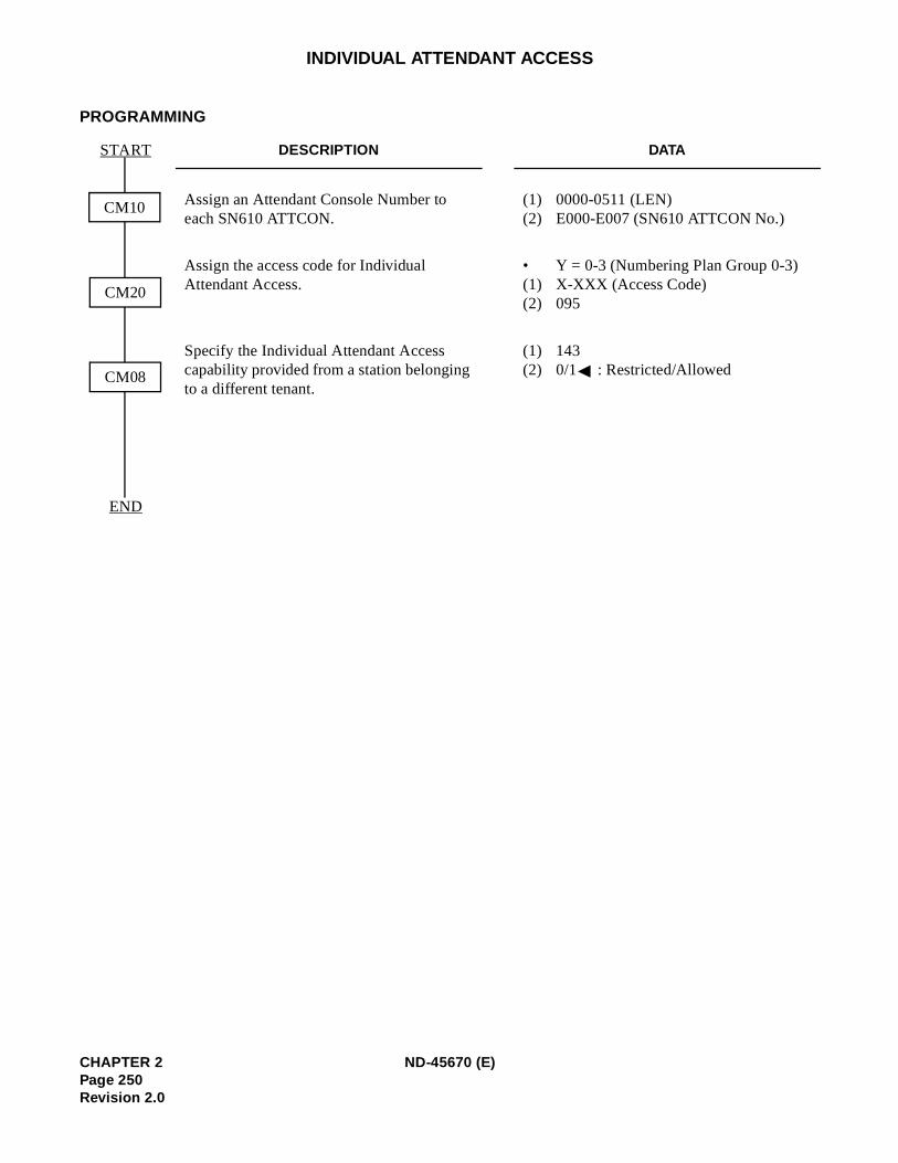
INDIVIDUAL ATTENDANT ACCESS
PROGRAMMING
DESCRIPTION DATA
Assign an Attendant Console Number to each SN610 ATTCON.
(1) 0000-0511 (LEN) (2) E000-E007 (SN610 ATTCON No.)
Assign the access code for Individual Attendant Access.
• Y = 0-3 (Numbering Plan Group 0-3) (1) X-XXX (Access Code) (2) 095
Specify the Individual Attendant Access capability provided from a station belonging to a different tenant.
(1) 143(2) 0/1 : Restricted/Allowed
START
END
CM10
CM08
CM20
CHAPTER 2 ND-45670 (E)Page 250Revision 2.0
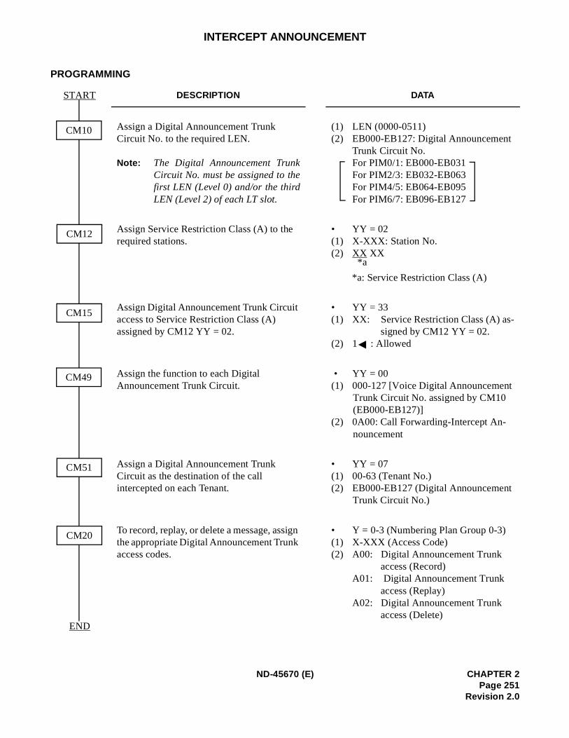
INTERCEPT ANNOUNCEMENT
PROGRAMMING
DESCRIPTION DATA
Assign a Digital Announcement Trunk Circuit No. to the required LEN.
Note: The Digital Announcement TrunkCircuit No. must be assigned to thefirst LEN (Level 0) and/or the thirdLEN (Level 2) of each LT slot.
(1) LEN (0000-0511) (2) EB000-EB127: Digital Announcement
Trunk Circuit No. For PIM0/1: EB000-EB031 For PIM2/3: EB032-EB063 For PIM4/5: EB064-EB095 For PIM6/7: EB096-EB127
Assign Service Restriction Class (A) to the required stations.
• YY = 02 (1) X-XXX: Station No. (2) XX XX
*a: Service Restriction Class (A)
Assign Digital Announcement Trunk Circuit access to Service Restriction Class (A) assigned by CM12 YY = 02.
• YY = 33(1) XX: Service Restriction Class (A) as-
signed by CM12 YY = 02.(2) 1 : Allowed
Assign the function to each Digital Announcement Trunk Circuit.
• YY = 00 (1) 000-127 [Voice Digital Announcement
Trunk Circuit No. assigned by CM10 (EB000-EB127)]
(2) 0A00: Call Forwarding-Intercept An-nouncement
Assign a Digital Announcement Trunk Circuit as the destination of the call intercepted on each Tenant.
• YY = 07(1) 00-63 (Tenant No.) (2) EB000-EB127 (Digital Announcement
Trunk Circuit No.)
To record, replay, or delete a message, assign the appropriate Digital Announcement Trunk access codes.
• Y = 0-3 (Numbering Plan Group 0-3) (1) X-XXX (Access Code) (2) A00: Digital Announcement Trunk
access (Record) A01: Digital Announcement Trunk
access (Replay) A02: Digital Announcement Trunk
access (Delete)
START
END
CM10
CM20
CM12
CM15
CM49
CM51
*a
ND-45670 (E) CHAPTER 2Page 251
Revision 2.0
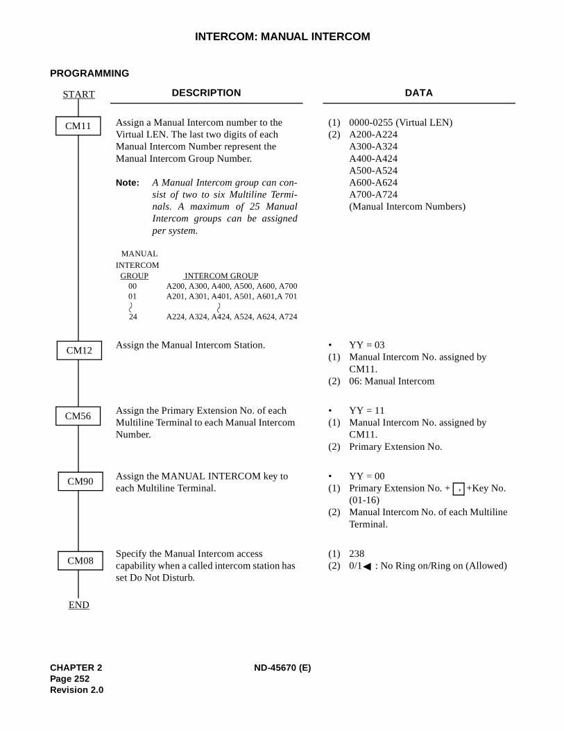
INTERCOM: MANUAL INTERCOM
PROGRAMMING
DESCRIPTION DATA
Assign a Manual Intercom number to the Virtual LEN. The last two digits of each Manual Intercom Number represent the Manual Intercom Group Number.
Note: A Manual Intercom group can con-sist of two to six Multiline Termi-nals. A maximum of 25 ManualIntercom groups can be assignedper system.
MANUAL
INTERCOM GROUP INTERCOM GROUP
00 A200, A300, A400, A500, A600, A70001 A201, A301, A401, A501, A601,A 701
24 A224, A324, A424, A524, A624, A724
(1) 0000-0255 (Virtual LEN) (2) A200-A224
A300-A324 A400-A424 A500-A524 A600-A624 A700-A724(Manual Intercom Numbers)
Assign the Manual Intercom Station. • YY = 03(1) Manual Intercom No. assigned by
CM11.(2) 06: Manual Intercom
Assign the Primary Extension No. of each Multiline Terminal to each Manual Intercom Number.
• YY = 11 (1) Manual Intercom No. assigned by
CM11. (2) Primary Extension No.
Assign the MANUAL INTERCOM key to each Multiline Terminal.
• YY = 00 (1) Primary Extension No. + +Key No.
(01-16) (2) Manual Intercom No. of each Multiline
Terminal.
Specify the Manual Intercom access capability when a called intercom station has set Do Not Disturb.
(1) 238 (2) 0/1 : No Ring on/Ring on (Allowed)
START
END
CM11
CM08
CM12
CM56
CM90 ,
CHAPTER 2 ND-45670 (E)Page 252Revision 2.0
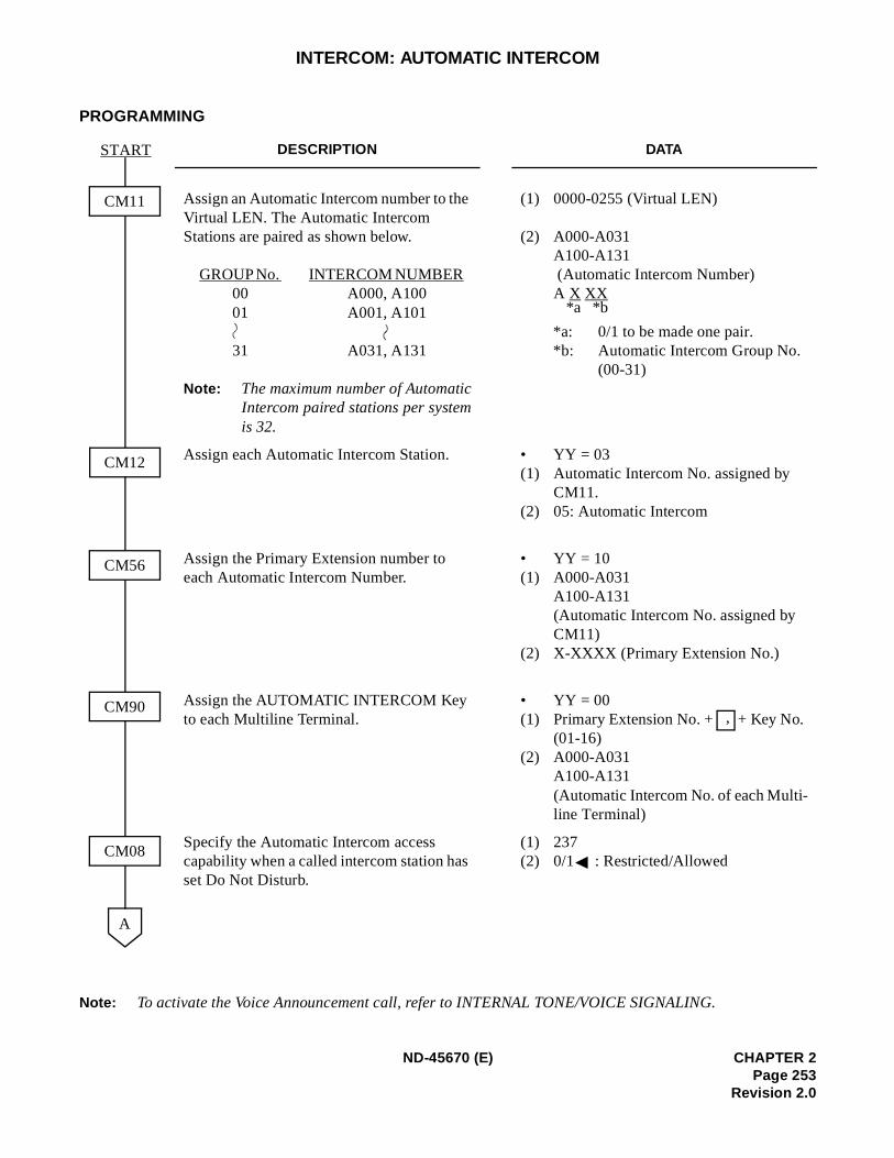
INTERCOM: AUTOMATIC INTERCOM
PROGRAMMING
Note: To activate the Voice Announcement call, refer to INTERNAL TONE/VOICE SIGNALING.
DESCRIPTION DATA
Assign an Automatic Intercom number to the Virtual LEN. The Automatic Intercom Stations are paired as shown below.
GROUP No. INTERCOM NUMBER 00 A000, A100
01 A001, A101
31 A031, A131
Note: The maximum number of AutomaticIntercom paired stations per systemis 32.
(1) 0000-0255 (Virtual LEN)
(2) A000-A031 A100-A131 (Automatic Intercom Number) A X XX
*a: 0/1 to be made one pair.*b: Automatic Intercom Group No.
(00-31)
Assign each Automatic Intercom Station. • YY = 03(1) Automatic Intercom No. assigned by
CM11. (2) 05: Automatic Intercom
Assign the Primary Extension number to each Automatic Intercom Number.
• YY = 10(1) A000-A031
A100-A131 (Automatic Intercom No. assigned by CM11)
(2) X-XXXX (Primary Extension No.)
Assign the AUTOMATIC INTERCOM Key to each Multiline Terminal.
• YY = 00 (1) Primary Extension No. + + Key No.
(01-16) (2) A000-A031
A100-A131 (Automatic Intercom No. of each Multi-line Terminal)
Specify the Automatic Intercom access capability when a called intercom station has set Do Not Disturb.
(1) 237(2) 0/1 : Restricted/Allowed
A
START
CM90
CM08
CM12
CM56
CM11
*a *b
,
ND-45670 (E) CHAPTER 2Page 253
Revision 2.0
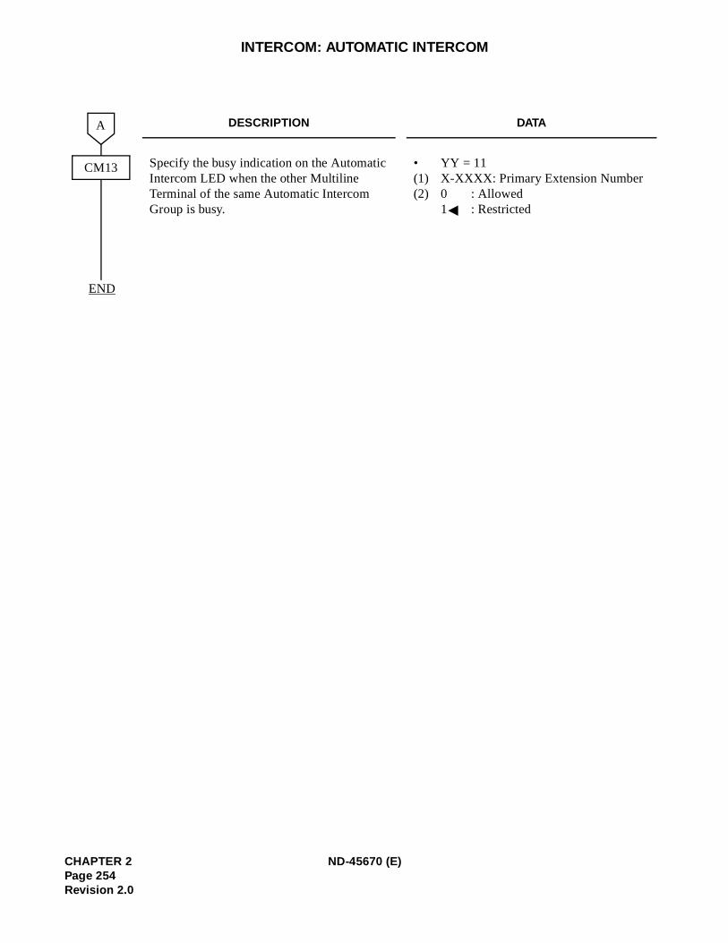
INTERCOM: AUTOMATIC INTERCOM
DESCRIPTION DATA
Specify the busy indication on the Automatic Intercom LED when the other Multiline Terminal of the same Automatic Intercom Group is busy.
• YY = 11(1) X-XXXX: Primary Extension Number (2) 0 : Allowed
1 : Restricted
END
CM13
A
CHAPTER 2 ND-45670 (E)Page 254Revision 2.0
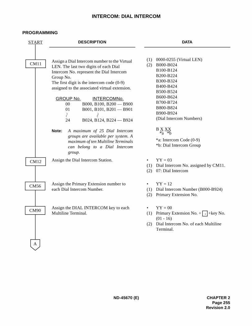
INTERCOM: DIAL INTERCOM
PROGRAMMING
DESCRIPTION DATA
Assign a Dial Intercom number to the Virtual LEN. The last two digits of each Dial Intercom No. represent the Dial Intercom Group No. The first digit is the intercom code (0-9) assigned to the associated virtual extension.
GROUP No. INTERCOM No. 00 B000, B100, B200 — B90001 B001, B101, B201 — B901
24 B024, B124, B224 — B924
Note: A maximum of 25 Dial Intercomgroups are available per system. Amaximum of ten Multiline Terminalscan belong to a Dial Intercomgroup.
(1) 0000-0255 (Virtual LEN) (2) B000-B024
B100-B124 B200-B224B300-B324 B400-B424 B500-B524 B600-B624 B700-B724 B800-B824 B900-B924(Dial Intercom Numbers)
B X XX
*a: Intercom Code (0-9) *b: Dial Intercom Group
Assign the Dial Intercom Station. • YY = 03 (1) Dial Intercom No. assigned by CM11.(2) 07: Dial Intercom
Assign the Primary Extension number to each Dial Intercom Number.
• YY = 12(1) Dial Intercom Number (B000-B924) (2) Primary Extension No.
Assign the DIAL INTERCOM key to each Multiline Terminal.
• YY = 00 (1) Primary Extension No. + +key No.
(01 - 16) (2) Dial Intercom No. of each Multiline
Terminal.
A
START
CM90
CM12
CM56
CM11
*a *b
,
ND-45670 (E) CHAPTER 2Page 255
Revision 2.0
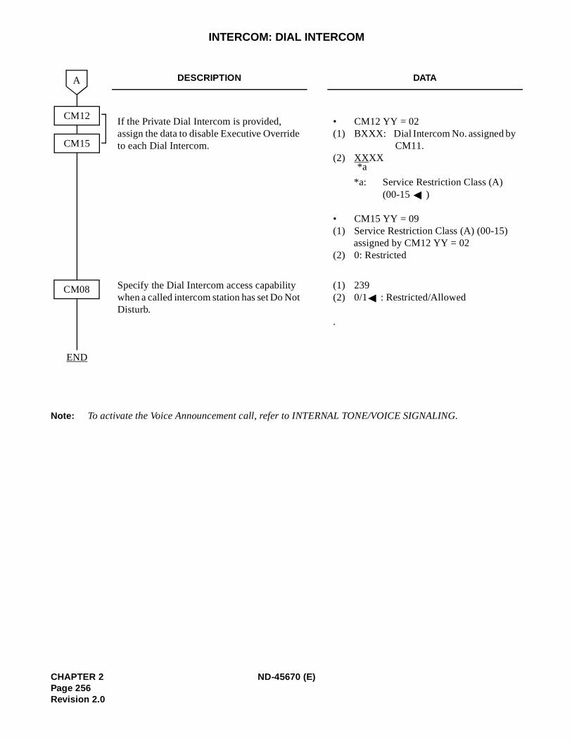
INTERCOM: DIAL INTERCOM
Note: To activate the Voice Announcement call, refer to INTERNAL TONE/VOICE SIGNALING.
DESCRIPTION DATA
If the Private Dial Intercom is provided, assign the data to disable Executive Override to each Dial Intercom.
• CM12 YY = 02 (1) BXXX: Dial Intercom No. assigned by
CM11.(2) XXXX
*a: Service Restriction Class (A) (00-15 )
• CM15 YY = 09(1) Service Restriction Class (A) (00-15)
assigned by CM12 YY = 02 (2) 0: Restricted
Specify the Dial Intercom access capability when a called intercom station has set Do Not Disturb.
(1) 239 (2) 0/1 : Restricted/Allowed
.
END
A
CM08
CM12
CM15
*a
CHAPTER 2 ND-45670 (E)Page 256Revision 2.0
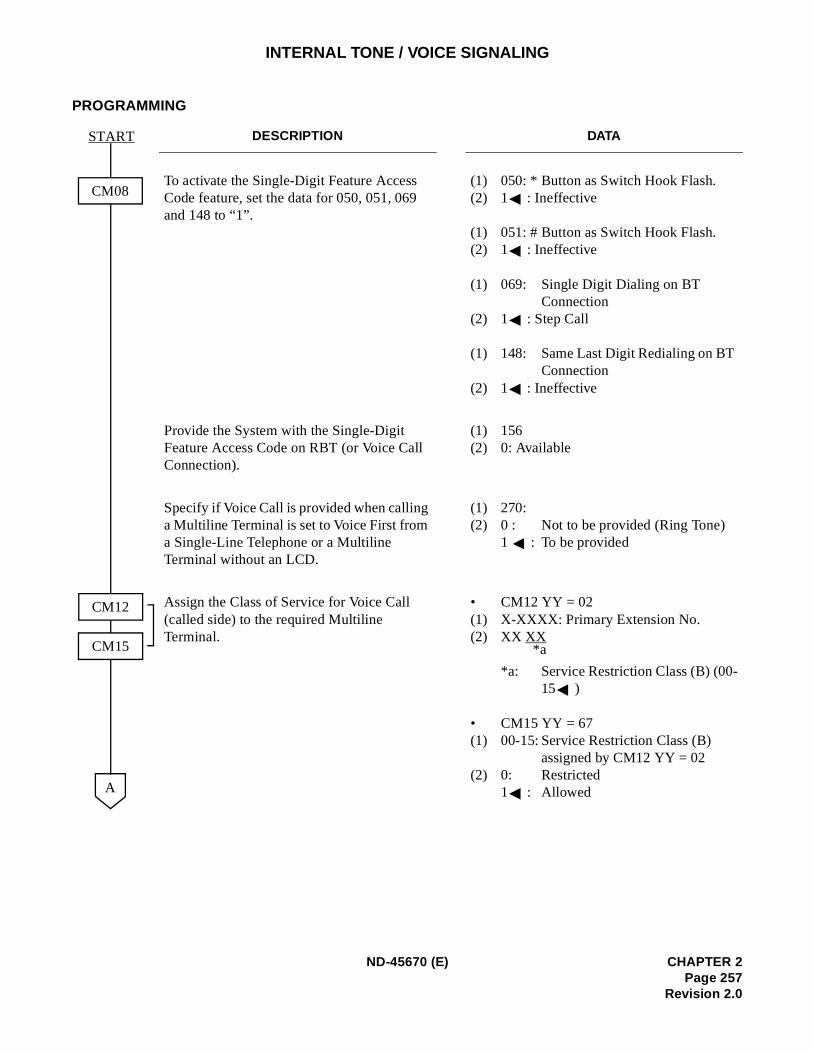
INTERNAL TONE / VOICE SIGNALING
PROGRAMMING
DESCRIPTION DATA
To activate the Single-Digit Feature Access Code feature, set the data for 050, 051, 069 and 148 to “1”.
(1) 050: * Button as Switch Hook Flash.(2) 1 : Ineffective
(1) 051: # Button as Switch Hook Flash.(2) 1 : Ineffective
(1) 069: Single Digit Dialing on BT Connection
(2) 1 : Step Call
(1) 148: Same Last Digit Redialing on BT Connection
(2) 1 : Ineffective
Provide the System with the Single-Digit Feature Access Code on RBT (or Voice Call Connection).
(1) 156(2) 0: Available
Specify if Voice Call is provided when calling a Multiline Terminal is set to Voice First from a Single-Line Telephone or a Multiline Terminal without an LCD.
(1) 270:(2) 0 : Not to be provided (Ring Tone) 1 : To be provided
Assign the Class of Service for Voice Call (called side) to the required Multiline Terminal.
• CM12 YY = 02(1) X-XXXX: Primary Extension No.(2) XX XX
*a: Service Restriction Class (B) (00-15 )
• CM15 YY = 67(1) 00-15: Service Restriction Class (B)
assigned by CM12 YY = 02(2) 0: Restricted
1 : AllowedA
START
CM08
CM12
CM15 *a
ND-45670 (E) CHAPTER 2Page 257
Revision 2.0
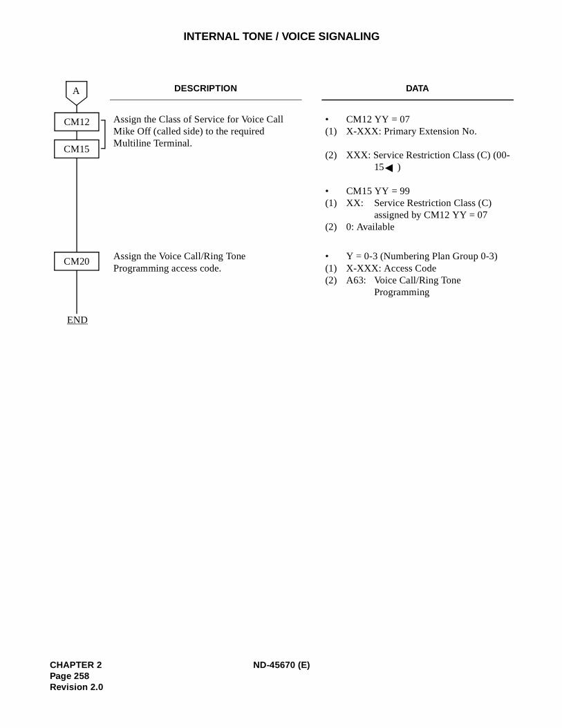
INTERNAL TONE / VOICE SIGNALING
DESCRIPTION DATA
Assign the Class of Service for Voice Call Mike Off (called side) to the required Multiline Terminal.
• CM12 YY = 07(1) X-XXX: Primary Extension No.
(2) XXX: Service Restriction Class (C) (00-15 )
• CM15 YY = 99(1) XX: Service Restriction Class (C)
assigned by CM12 YY = 07(2) 0: Available
Assign the Voice Call/Ring Tone Programming access code.
• Y = 0-3 (Numbering Plan Group 0-3)(1) X-XXX: Access Code(2) A63: Voice Call/Ring Tone
Programming
END
CM12
CM15
CM20
A
CHAPTER 2 ND-45670 (E)Page 258Revision 2.0
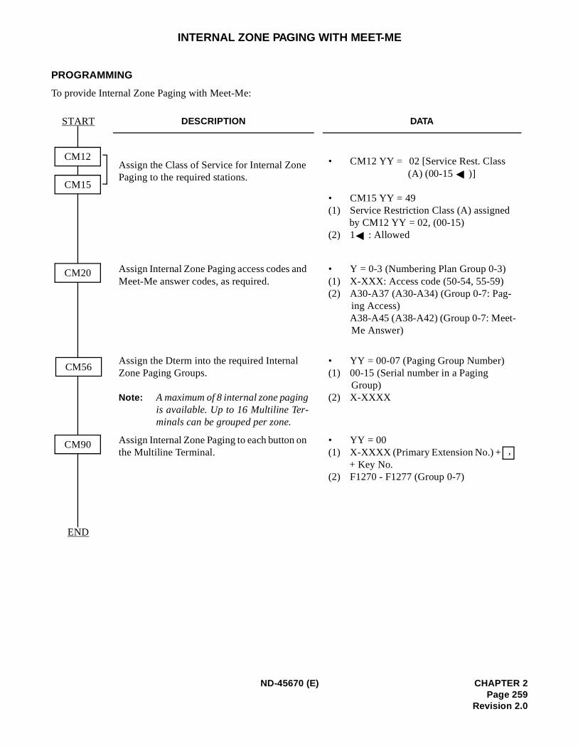
INTERNAL ZONE PAGING WITH MEET-ME
PROGRAMMING
To provide Internal Zone Paging with Meet-Me:
DESCRIPTION DATA
Assign the Class of Service for Internal Zone Paging to the required stations.
• CM12 YY = 02 [Service Rest. Class (A) (00-15 )]
• CM15 YY = 49(1) Service Restriction Class (A) assigned
by CM12 YY = 02, (00-15) (2) 1 : Allowed
Assign Internal Zone Paging access codes and Meet-Me answer codes, as required.
• Y = 0-3 (Numbering Plan Group 0-3) (1) X-XXX: Access code (50-54, 55-59) (2) A30-A37 (A30-A34) (Group 0-7: Pag-
ing Access) A38-A45 (A38-A42) (Group 0-7: Meet-Me Answer)
Assign the Dterm into the required Internal Zone Paging Groups.
Note: A maximum of 8 internal zone pagingis available. Up to 16 Multiline Ter-minals can be grouped per zone.
• YY = 00-07 (Paging Group Number) (1) 00-15 (Serial number in a Paging
Group) (2) X-XXXX
Assign Internal Zone Paging to each button on the Multiline Terminal.
• YY = 00 (1) X-XXXX (Primary Extension No.) +
+ Key No. (2) F1270 - F1277 (Group 0-7)
START
END
CM12
CM15
CM20
CM56
CM90,
ND-45670 (E) CHAPTER 2Page 259
Revision 2.0
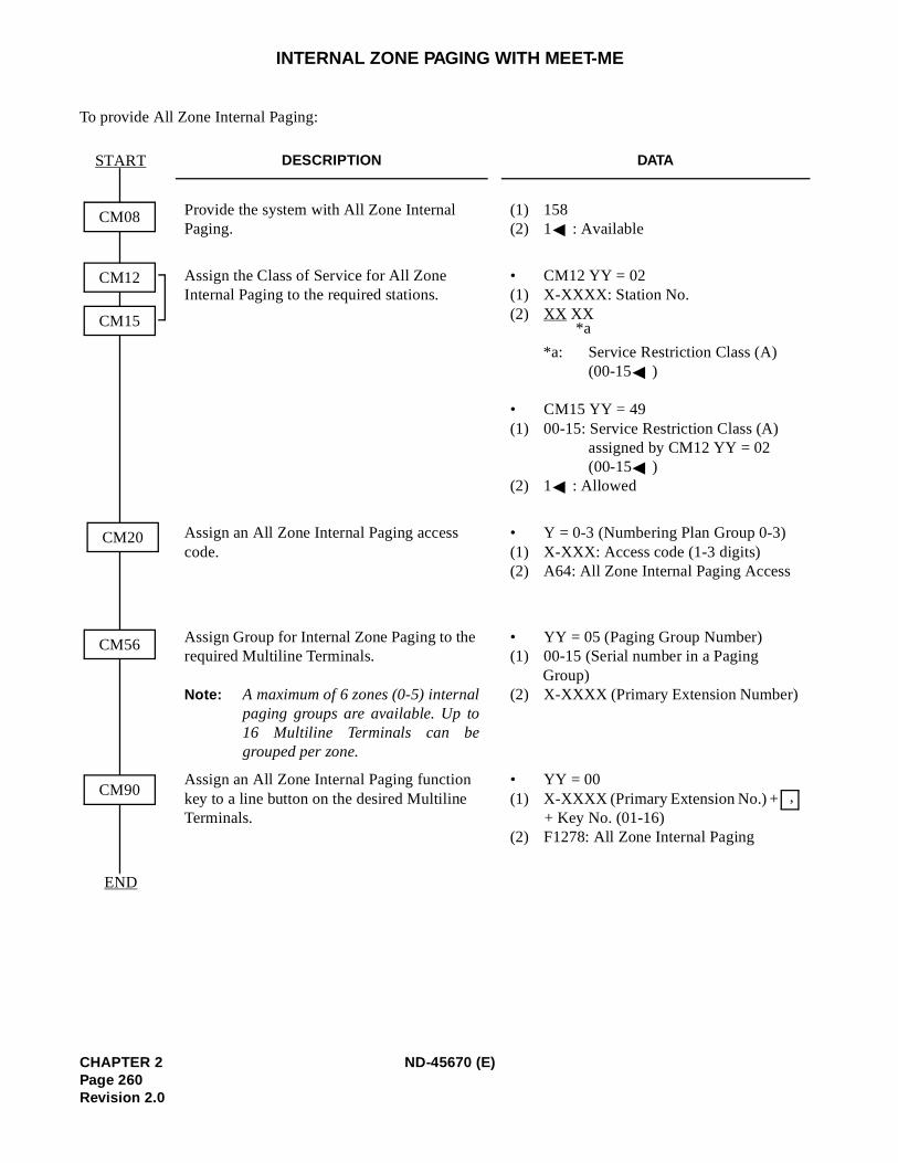
INTERNAL ZONE PAGING WITH MEET-ME
To provide All Zone Internal Paging:
DESCRIPTION DATA
Provide the system with All Zone Internal Paging.
(1) 158 (2) 1 : Available
Assign the Class of Service for All Zone Internal Paging to the required stations.
• CM12 YY = 02(1) X-XXXX: Station No. (2) XX XX
*a: Service Restriction Class (A) (00-15 )
• CM15 YY = 49(1) 00-15: Service Restriction Class (A)
assigned by CM12 YY = 02 (00-15 )
(2) 1 : Allowed
Assign an All Zone Internal Paging access code.
• Y = 0-3 (Numbering Plan Group 0-3) (1) X-XXX: Access code (1-3 digits) (2) A64: All Zone Internal Paging Access
Assign Group for Internal Zone Paging to the required Multiline Terminals.
Note: A maximum of 6 zones (0-5) internalpaging groups are available. Up to16 Multiline Terminals can begrouped per zone.
• YY = 05 (Paging Group Number) (1) 00-15 (Serial number in a Paging
Group) (2) X-XXXX (Primary Extension Number)
Assign an All Zone Internal Paging function key to a line button on the desired Multiline Terminals.
• YY = 00 (1) X-XXXX (Primary Extension No.) +
+ Key No. (01-16) (2) F1278: All Zone Internal Paging
START
END
CM12
CM15
CM20
CM56
CM90
CM08
*a
,
CHAPTER 2 ND-45670 (E)Page 260Revision 2.0
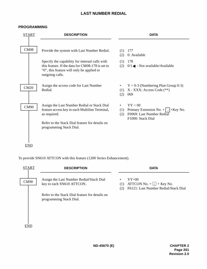
LAST NUMBER REDIAL
PROGRAMMING
To provide SN610 ATTCON with this feature (1200 Series Enhancement).
DESCRIPTION DATA
Provide the system with Last Number Redial. (1) 177(2) 0: Available
Specify the capability for internal calls with this feature. If the data for CM08-178 is set to “0”, this feature will only be applied to outgoing calls.
(1) 178(2) 0/1 : Not available/Available
Assign the access code for Last Number Redial.
• Y = 0-3 (Numbering Plan Group 0-3)(1) X - XXX: Access Code (**)(2) 069
Assign the Last Number Redial or Stack Dial feature access key to each Multiline Terminal, as required.
Refer to the Stack Dial feature for details on programming Stack Dial.
• YY = 00(1) Primary Extension No. + +Key No. (2) F0069: Last Number Redial
F1000: Stack Dial
DESCRIPTION DATA
Assign the Last Number Redial/Stack Dial key to each SN610 ATTCON.
• YY=00(1) ATTCON No. + + Key No. (2) F6121: Last Number Redial/Stack Dial
Refer to the Stack Dial feature for details on programming Stack Dial.
START
END
CM08
CM20
CM90,
END
CM90
START
,
ND-45670 (E) CHAPTER 2Page 261
Revision 2.0
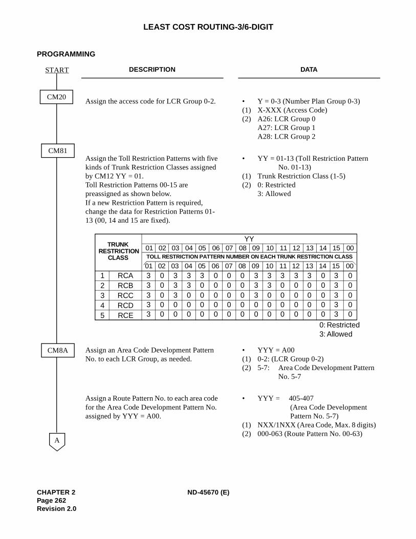
LEAST COST ROUTING-3/6-DIGIT
PROGRAMMING
DESCRIPTION DATA
Assign the access code for LCR Group 0-2. • Y = 0-3 (Number Plan Group 0-3)(1) X-XXX (Access Code) (2) A26: LCR Group 0
A27: LCR Group 1 A28: LCR Group 2
Assign the Toll Restriction Patterns with five kinds of Trunk Restriction Classes assigned by CM12 YY = 01. Toll Restriction Patterns 00-15 are preassigned as shown below. If a new Restriction Pattern is required, change the data for Restriction Patterns 01-13 (00, 14 and 15 are fixed).
• YY = 01-13 (Toll Restriction Pattern No. 01-13)
(1) Trunk Restriction Class (1-5) (2) 0: Restricted
3: Allowed
Assign an Area Code Development Pattern No. to each LCR Group, as needed.
• YYY = A00(1) 0-2: (LCR Group 0-2) (2) 5-7: Area Code Development Pattern
No. 5-7
Assign a Route Pattern No. to each area code for the Area Code Development Pattern No. assigned by YYY = A00.
• YYY = 405-407 (Area Code Development Pattern No. 5-7)
(1) NXX/1NXX (Area Code, Max. 8 digits)(2) 000-063 (Route Pattern No. 00-63)
CM20
START
CM81
CM8A
A
YYTRUNK
RESTRICTIONCLASS
01 02 03 04 05 06 07 08 09 10 11 12 13 14 15 00
01 02 03 04 05 06 07 08 09 10 11 12 13 14 15 00TOLL RESTRICTION PATTERN NUMBER ON EACH TRUNK RESTRICTION CLASS
12345
RCARCBRCCRCDRCE
33333
00000
33300
33000
30000
00000
00000
00000
33300
33000
30000
30000
30000
00000
33333
00000
0:3:
RestrictedAllowed
CHAPTER 2 ND-45670 (E)Page 262Revision 2.0
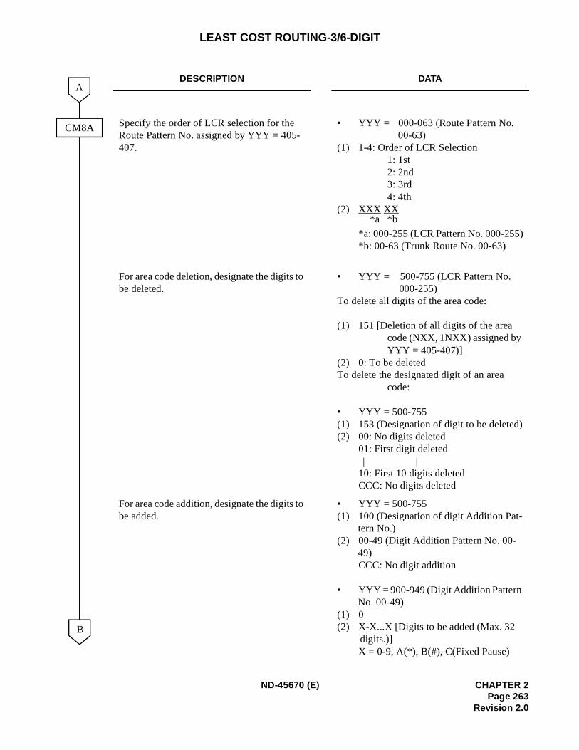
LEAST COST ROUTING-3/6-DIGIT
DESCRIPTION DATA
Specify the order of LCR selection for the Route Pattern No. assigned by YYY = 405-407.
• YYY = 000-063 (Route Pattern No. 00-63)
(1) 1-4: Order of LCR Selection1: 1st2: 2nd3: 3rd4: 4th
(2) XXX XX
*a: 000-255 (LCR Pattern No. 000-255)*b: 00-63 (Trunk Route No. 00-63)
For area code deletion, designate the digits to be deleted.
• YYY = 500-755 (LCR Pattern No. 000-255)
To delete all digits of the area code:
(1) 151 [Deletion of all digits of the area code (NXX, 1NXX) assigned by YYY = 405-407)]
(2) 0: To be deleted To delete the designated digit of an area
code:
• YYY = 500-755(1) 153 (Designation of digit to be deleted)(2) 00: No digits deleted
01: First digit deleted
10: First 10 digits deleted CCC: No digits deleted
For area code addition, designate the digits to be added.
• YYY = 500-755(1) 100 (Designation of digit Addition Pat-
tern No.) (2) 00-49 (Digit Addition Pattern No. 00-
49) CCC: No digit addition
• YYY = 900-949 (Digit Addition Pattern No. 00-49)
(1) 0 (2) X-X...X [Digits to be added (Max. 32
digits.)] X = 0-9, A(*), B(#), C(Fixed Pause)
CM8A
B
A
*b*a
| |
ND-45670 (E) CHAPTER 2Page 263
Revision 2.0
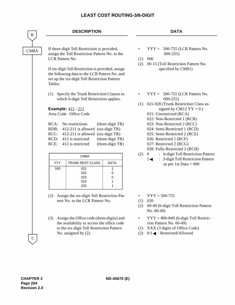
LEAST COST ROUTING-3/6-DIGIT
DESCRIPTION DATA
If three-digit Toll Restriction is provided, assign the Toll Restriction Pattern No. to the LCR Pattern No.
If six-digit Toll Restriction is provided, assign the following data to the LCR Pattern No. and set up the six-digit Toll Restriction Pattern Tables.
(1) Specify the Trunk Restriction Classes to which 6-digit Toll Restriction applies.
Example: 412 - 211Area Code Office Code
RCA: No restrictions (three-digit TR)RDB: 412-211 is allowed (six-digit TR)RCC: 412-211 is allowed (six-digit TR)RCD: 412 is restricted (three-digit TR)RCE: 412 is restricted (three-digit TR)
• YYY = 500-755 (LCR Pattern No. 000-255)
(1) 000 (2) 00-15 (Toll Restriction Pattern No.
specified by CM81)
• YYY = 500-755 (LCR Pattern No. 000-255)
(1) 021-028 (Trunk Restriction Class as-signed by CM12 YY = 0.)
021: Unrestricted (RCA) 022: Non-Restricted 1 (RCB) 023: Non-Restricted 2 (RCC) 024: Semi-Restricted 1 (RCD)025: Semi-Restricted 2 (RCE)026: Restricted 1 (RCF) 027: Restricted 2 (RCG) 028: Fully-Restricted 2 (RCH)
(2) 0 : 6-digit Toll Restriction Pattern1 : 3-digit Toll Restriction Pattern
as per 1st Data = 000
(2) Assign the six-digit Toll Restriction Pat-tern No. to the LCR Pattern No.
• YYY = 500-755 (1) 020 (2) 00-49 (6-digit Toll Restriction Pattern
No. 00-49)
(3) Assign the Office code (three-digits) and the availability to access the office code to the six-digit Toll Restriction Pattern No. assigned by (2).
• YYY = 800-849 (6-digit Toll Restric-tion Pattern No. 00-49)
(1) XXX (3 digits of Office Code) (2) 0/1 : Restricted/Allowed
CM8A
C
B
021022023024025
500 10011
CM8A
TRUNK REST CLASS DATAYYY
CHAPTER 2 ND-45670 (E)Page 264Revision 2.0
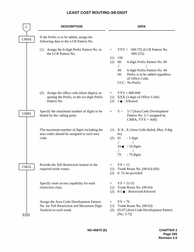
LEAST COST ROUTING-3/6-DIGIT
DESCRIPTION DATA
If the Prefix is to be added, assign the following data to the LCR Pattern No.
(1) Assign the 6-digit Prefix Pattern No. to the LCR Pattern No.
• YYY = 500-755 (LCR Pattern No. 000-255)
(1) 150 (2) 00: 6-digit Prefix Pattern No. 00
49: 6-digit Prefix Pattern No. 4950: Prefix is to be added regardless
of Office Code.CCC: No Prefix
(2) Assign the office code (three digits), re-quiring the Prefix, to the six-digit Prefix Pattern No.
• YYY = 800-849(1) XXX (3-digit of Office Code)(2) 1 : Allowed
Specify the maximum number of digits to be dialed by the calling party.
• Y = 5-7 (Area Code Development Pattern No. 5-7 assigned by CM8A, YYY = A00)
The maximum number of digits including the area codes should be assigned to each area code.
(1) X-X...X (Area Code dialed, Max. 8 dig-its)
(2) 01 : 1 digit
24 : 24 digits
79 : 79 digits
Provide the Toll Restriction feature to the required trunk routes.
• YY = 11(1) Trunk Route No. (00-63) (00) (2) 0: To be provided
Specify route access capability for each restriction class.
• YY = 51-55 (1) Trunk Route No. (00-63)(2) 0/1 : Restricted/Allowed
Assign the Area Code Development Pattern No. for Toll Restriction and Maximum Digit Analysis to each trunk.
• YY = 76(1) Trunk Route No. (00-63)(2) 05-07 [Area Code Development Pattern
(No. 5-7)]
CM8A
C
END
CM85
CM35
ND-45670 (E) CHAPTER 2Page 265
Revision 2.0
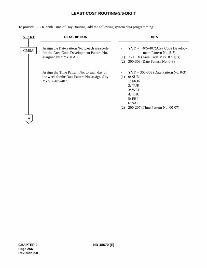
LEAST COST ROUTING-3/6-DIGIT
To provide L.C.R. with Time of Day Routing, add the following system data programming.
DESCRIPTION DATA
Assign the Date Pattern No. to each area code for the Area Code Development Pattern No. assigned by YYY = A00.
• YYY = 405-407(Area Code Develop-ment Pattern No. 5-7)
(1) X-X...X (Area Code Max. 8 digits)(2) 300-303 (Date Pattern No. 0-3)
Assign the Time Pattern No. to each day of the week for the Date Pattern No. assigned by YYY = 405-407.
• YYY = 300-303 (Date Pattern No. 0-3) (1) 0: SUN
1: MON 2: TUE 3: WED 4: THU 5: FRI 6: SAT
(2) 200-207 (Time Pattern No. 00-07)
CM8A
A
START
CHAPTER 2 ND-45670 (E)Page 266Revision 2.0
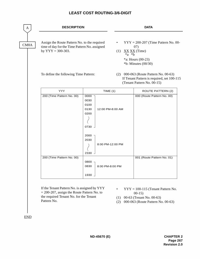
LEAST COST ROUTING-3/6-DIGIT
DESCRIPTION DATA
Assign the Route Pattern No. to the required time of day for the Time Pattern No. assigned by YYY = 300-303.
• YYY = 200-207 (Time Pattern No. 00-07)
(1) XX XX (Time)
*a: Hours (00-23) *b: Minutes (00/30)
To define the following Time Pattern:
If the Tenant Pattern No. is assigned by YYY = 200-207, assign the Route Pattern No. to the required Tenant No. for the Tenant Pattern No.
(2) 000-063 (Route Pattern No. 00-63) If Tenant Pattern is required, set 100-115(Tenant Pattern No. 00-15)
• YYY = 100-115 (Tenant Pattern No. 00-15)
(1) 00-63 (Tenant No. 00-63) (2) 000-063 (Route Pattern No. 00-63)
CM8A
A
END
*b*a
0000
0030
0100
0130
0200
0730
2000
2030
2330
0800
0830
1930
YYY TIME (1) ROUTE PATTERN (2)
200 (Time Pattern No. 00)
200 (Time Pattern No. 00)
12:00 PM-8:00 AM
8:00 PM-12:00 PM
8:00 PM-8:00 PM
000 (Route Pattern No. 00)
001 (Route Pattern No. 01)
ND-45670 (E) CHAPTER 2Page 267
Revision 2.0
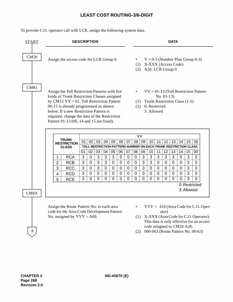
LEAST COST ROUTING-3/6-DIGIT
To provide C.O. operator call with LCR, assign the following system data.
DESCRIPTION DATA
Assign the access code for LCR Group 0. • Y = 0-3 (Number Plan Group 0-3) (1) X-XXX (Access Code) (2) A26: LCR Group 0
Assign the Toll Restriction Patterns with five kinds of Trunk Restriction Classes assigned by CM12 YY = 01. Toll Restriction Pattern 00-15 is already programmed as shown below. If a new Restriction Pattern is required, change the data of the Restriction Pattern 01-13 (00, 14 and 15 are fixed).
• YY = 01-13 (Toll Restriction Pattern No. 01-13)
(1) Trunk Restriction Class (1-5) (2) 0: Restricted
3: Allowed
Assign the Route Pattern No. to each area code for the Area Code Development Pattern No. assigned by YYY = A00.
• YYY = 410 (Area Code for C.O. Oper-ator)
(1) X-XXX (Area Code for C.O. Operator). This data is only effective for an accesscode assigned to CM20-A26.
(2) 000-063 (Route Pattern No. 00-63)
CM20
A
START
CM81
CM8A
YYTRUNK
RESTRICTIONCLASS
01 02 03 04 05 06 07 08 09 10 11 12 13 14 15 00
01 02 03 04 05 06 07 08 09 10 11 12 13 14 15 00TOLL RESTRICTION PATTERN NUMBER ON EACH TRUNK RESTRICTION CLASS
12345
RCARCBRCCRCDRCE
33333
00000
33300
33000
30000
00000
00000
00000
33300
33000
30000
30000
30000
00000
33333
00000
0:3:
RestrictedAllowed
CHAPTER 2 ND-45670 (E)Page 268Revision 2.0
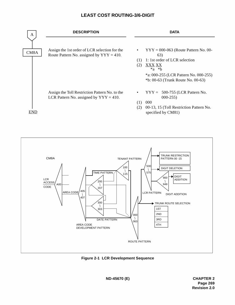
LEAST COST ROUTING-3/6-DIGIT
Figure 2-1 LCR Development Sequence
DESCRIPTION DATA
Assign the 1st order of LCR selection for the Route Pattern No. assigned by YYY = 410.
• YYY = 000-063 (Route Pattern No. 00-63)
(1) 1: 1st order of LCR selection (2) XXX XX
*a: 000-255 (LCR Pattern No. 000-255)*b: 00-63 (Trunk Route No. 00-63)
Assign the Toll Restriction Pattern No. to the LCR Pattern No. assigned by YYY = 410.
• YYY = 500-755 (LCR Pattern No. 000-255)
(1) 000 (2) 00-13, 15 (Toll Restriction Pattern No.
specified by CM81)
A
END
CM8A
*b*a
CM8A
LCRACCESS
CODEA00
AREA CODE 405
407
200
207
300
303
100
115
000
063
500
575TIME PATTERN
DATE PATTERN
TENANT PATTERN
AREA CODEDEVELOPMENT PATTERN
ROUTE PATTERN
LCR PATTERN DIGIT ADDITION
TRUNK ROUTE SELECTION
TRUNK RESTRICTIONPATTERN 00 -15
DIGIT DELETION
DIGIT ADDITION
900
949
1ST
2ND
3RD
4TH
ND-45670 (E) CHAPTER 2Page 269
Revision 2.0
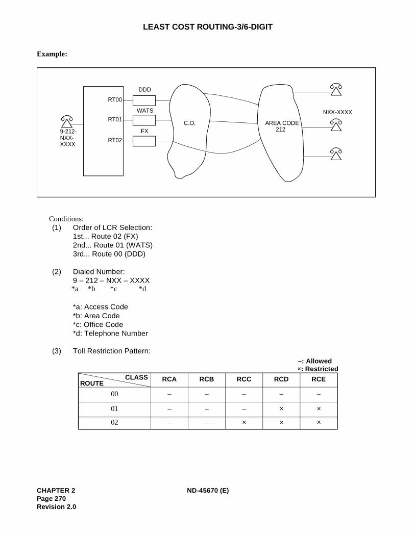
LEAST COST ROUTING-3/6-DIGIT
Example:
Conditions: (1) Order of LCR Selection:
1st... Route 02 (FX) 2nd... Route 01 (WATS) 3rd... Route 00 (DDD)
(2) Dialed Number:9 – 212 – NXX – XXXX
*a: Access Code *b: Area Code *c: Office Code *d: Telephone Number
(3) Toll Restriction Pattern:
RCA RCB RCC RCD RCE
00 – – – – –
01 – – – × ×
02 – – × × ×
9-212-NXX-XXXX
RT00
RT01
RT02
DDD
WATS
FXC.O. AREA CODE
212
NXX-XXXX
*b*a *c *d
–: Allowed×: Restricted
CLASSROUTE
CHAPTER 2 ND-45670 (E)Page 270Revision 2.0
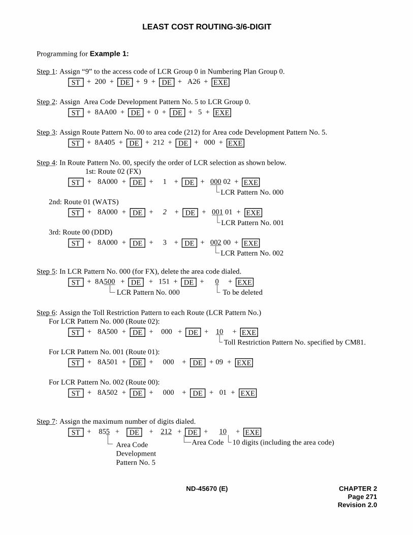
LEAST COST ROUTING-3/6-DIGIT
Programming for Example 1:
Step 1: Assign “9” to the access code of LCR Group 0 in Numbering Plan Group 0. + 200 + + 9 + + A26 +
Step 2: Assign Area Code Development Pattern No. 5 to LCR Group 0.
+ 8AA00 + + 0 + + 5 +
Step 3: Assign Route Pattern No. 00 to area code (212) for Area code Development Pattern No. 5. + 8A405 + + 212 + + 000 +
Step 4: In Route Pattern No. 00, specify the order of LCR selection as shown below.1st: Route 02 (FX)
+ 8A000 + + 1 + + 000 02 +
LCR Pattern No. 0002nd: Route 01 (WATS)
+ 8A000 + + 2 + + 001 01 +
LCR Pattern No. 0013rd: Route 00 (DDD)
+ 8A000 + + 3 + + 002 00 +
LCR Pattern No. 002
Step 5: In LCR Pattern No. 000 (for FX), delete the area code dialed. + 8A500 + + 151 + + 0 +
LCR Pattern No. 000 To be deleted
Step 6: Assign the Toll Restriction Pattern to each Route (LCR Pattern No.)For LCR Pattern No. 000 (Route 02):
+ 8A500 + + 000 + + 10 +
Toll Restriction Pattern No. specified by CM81.For LCR Pattern No. 001 (Route 01):
+ 8A501 + + 000 + + 09 +
For LCR Pattern No. 002 (Route 00):
+ 8A502 + + 000 + + 01 +
Step 7: Assign the maximum number of digits dialed. + 855 + + 212 + + 10 +
Area Code 10 digits (including the area code)
ST DE DE EXE
ST DE DE EXE
ST DE DE EXE
ST DE DE EXE
ST DE DE EXE
ST DE DE EXE
ST DE DE EXE
ST DE DE EXE
ST DE DE EXE
ST DE DE EXE
ST DE DE EXE
Area CodeDevelopment Pattern No. 5
ND-45670 (E) CHAPTER 2Page 271
Revision 2.0
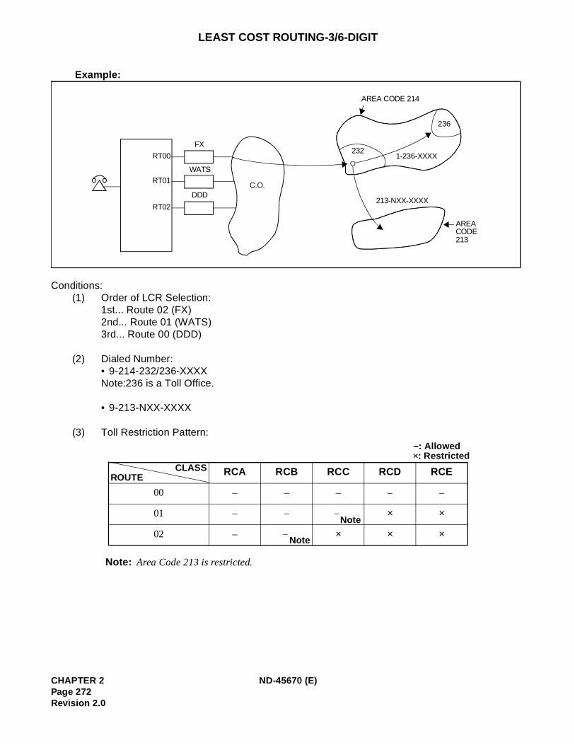
LEAST COST ROUTING-3/6-DIGIT
Example:
Conditions: (1) Order of LCR Selection:
1st... Route 02 (FX) 2nd... Route 01 (WATS) 3rd... Route 00 (DDD)
(2) Dialed Number:• 9-214-232/236-XXXX Note:236 is a Toll Office.
• 9-213-NXX-XXXX
(3) Toll Restriction Pattern:
Note: Area Code 213 is restricted.
RCA RCB RCC RCD RCE
00 – – – – –
01 – – × ×
02 – × × ×
RT00
RT01
RT02
DDD
WATS
FX
C.O.
AREA CODE 214
236
2321-236-XXXX
213-NXX-XXXX
AREA CODE 213
–: All owed×: Restricted
CLASSROUTE
Note–
Note–
CHAPTER 2 ND-45670 (E)Page 272Revision 2.0
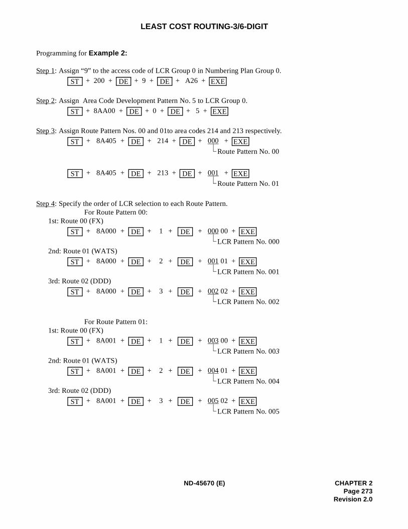
LEAST COST ROUTING-3/6-DIGIT
Programming for Example 2:
Step 1: Assign “9” to the access code of LCR Group 0 in Numbering Plan Group 0. + 200 + + 9 + + A26 +
Step 2: Assign Area Code Development Pattern No. 5 to LCR Group 0.
+ 8AA00 + + 0 + + 5 +
Step 3: Assign Route Pattern Nos. 00 and 01to area codes 214 and 213 respectively. + 8A405 + + 214 + + 000 +
Route Pattern No. 00
+ 8A405 + + 213 + + 001 +
Route Pattern No. 01
Step 4: Specify the order of LCR selection to each Route Pattern.For Route Pattern 00:
1st: Route 00 (FX)
+ 8A000 + + 1 + + 000 00 +
LCR Pattern No. 0002nd: Route 01 (WATS)
+ 8A000 + + 2 + + 001 01 +
LCR Pattern No. 0013rd: Route 02 (DDD)
+ 8A000 + + 3 + + 002 02 +
LCR Pattern No. 002
For Route Pattern 01:1st: Route 00 (FX)
+ 8A001 + + 1 + + 003 00 +
LCR Pattern No. 0032nd: Route 01 (WATS)
+ 8A001 + + 2 + + 004 01 +
LCR Pattern No. 0043rd: Route 02 (DDD)
+ 8A001 + + 3 + + 005 02 +
LCR Pattern No. 005
ST DE DE EXE
ST DE DE EXE
ST DE DE EXE
ST DE DE EXE
ST DE DE EXE
ST DE DE EXE
ST DE DE EXE
ST DE DE EXE
ST DE DE EXE
ST DE DE EXE
ND-45670 (E) CHAPTER 2Page 273
Revision 2.0
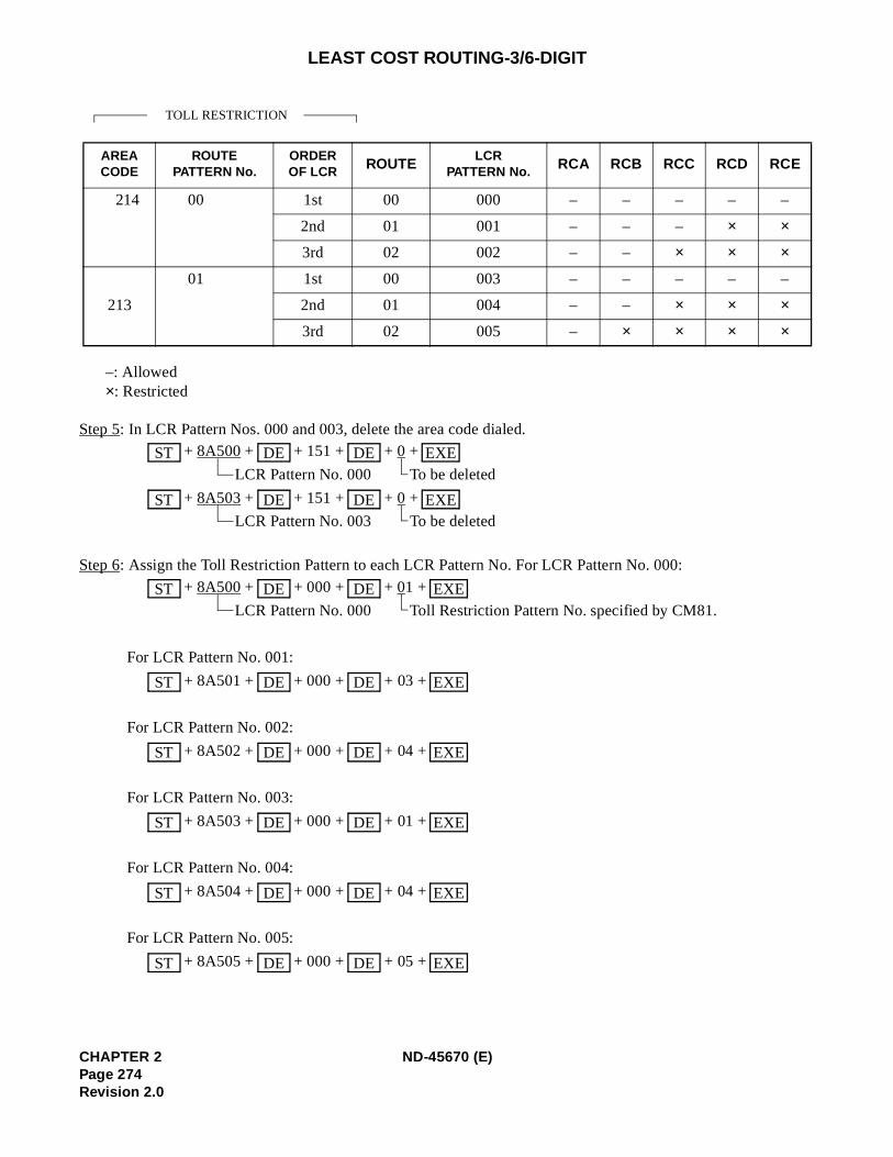
LEAST COST ROUTING-3/6-DIGIT
–: Allowed×: Restricted
Step 5: In LCR Pattern Nos. 000 and 003, delete the area code dialed. + 8A500 + + 151 + + 0 +
LCR Pattern No. 000 To be deleted
+ 8A503 + + 151 + + 0 +
LCR Pattern No. 003 To be deleted
Step 6: Assign the Toll Restriction Pattern to each LCR Pattern No. For LCR Pattern No. 000:
+ 8A500 + + 000 + + 01 +
LCR Pattern No. 000 Toll Restriction Pattern No. specified by CM81.
For LCR Pattern No. 001:
+ 8A501 + + 000 + + 03 +
For LCR Pattern No. 002:
+ 8A502 + + 000 + + 04 +
For LCR Pattern No. 003:
+ 8A503 + + 000 + + 01 +
For LCR Pattern No. 004:
+ 8A504 + + 000 + + 04 +
For LCR Pattern No. 005:
+ 8A505 + + 000 + + 05 +
AREA CODE
ROUTEPATTERN No.
ORDEROF LCR ROUTE
LCRPATTERN No. RCA RCB RCC RCD RCE
214 00 1st 00 000 – – – – –
2nd 01 001 – – – × ×
3rd 02 002 – – × × ×
213
01 1st 00 003 – – – – –
2nd 01 004 – – × × ×
3rd 02 005 – × × × ×
TOLL RESTRICTION
ST DE DE EXE
ST DE DE EXE
ST DE DE EXE
ST DE DE EXE
ST DE DE EXE
ST DE DE EXE
ST DE DE EXE
ST DE DE EXE
CHAPTER 2 ND-45670 (E)Page 274Revision 2.0
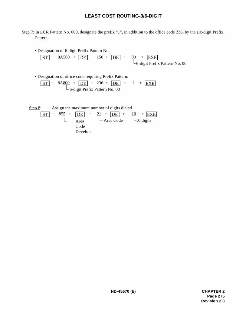
refix
LEAST COST ROUTING-3/6-DIGIT
Step 7: In LCR Pattern No. 000, designate the prefix “1”, in addition to the office code 236, by the six-digit PPattern.
• Designation of 6-digit Prefix Pattern No.
+ 8A500 + + 150 + + 00 +
6-digit Prefix Pattern No. 00
• Designation of office code requiring Prefix Pattern.
+ 8A800 + + 236 + + 1 +
6-digit Prefix Pattern No. 00
Step 8: Assign the maximum number of digits dialed. + 855 + + 21 + + 10 +
Area Code 10 digits
ST DE DE EXE
ST DE DE EXE
ST DE DE EXE
AreaCodeDevelop-
ND-45670 (E) CHAPTER 2Page 275
Revision 2.0
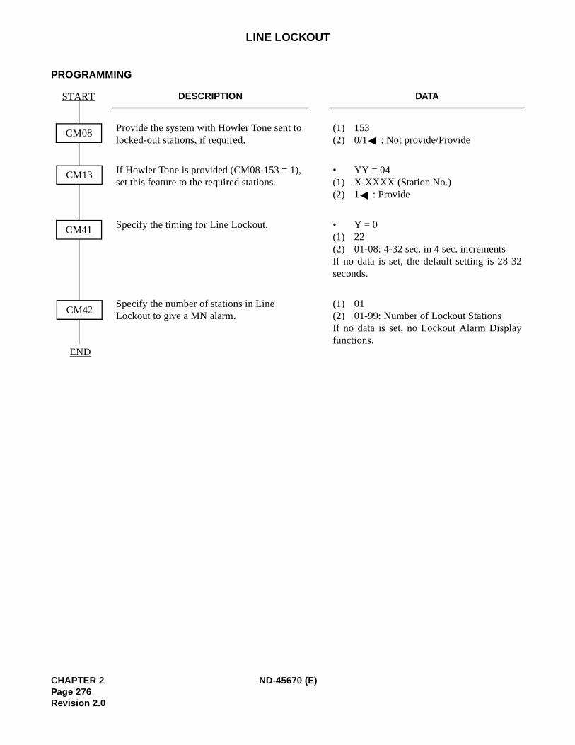
2
LINE LOCKOUT
PROGRAMMING
DESCRIPTION DATA
Provide the system with Howler Tone sent to locked-out stations, if required.
(1) 153(2) 0/1 : Not provide/Provide
If Howler Tone is provided (CM08-153 = 1), set this feature to the required stations.
• YY = 04(1) X-XXXX (Station No.)(2) 1 : Provide
Specify the timing for Line Lockout. • Y = 0(1) 22(2) 01-08: 4-32 sec. in 4 sec. incrementsIf no data is set, the default setting is 28-3seconds.
Specify the number of stations in Line Lockout to give a MN alarm.
(1) 01(2) 01-99: Number of Lockout Stations If no data is set, no Lockout Alarm Displayfunctions.
CM08
START
CM13
CM41
CM42
END
CHAPTER 2 ND-45670 (E)Page 276Revision 2.0
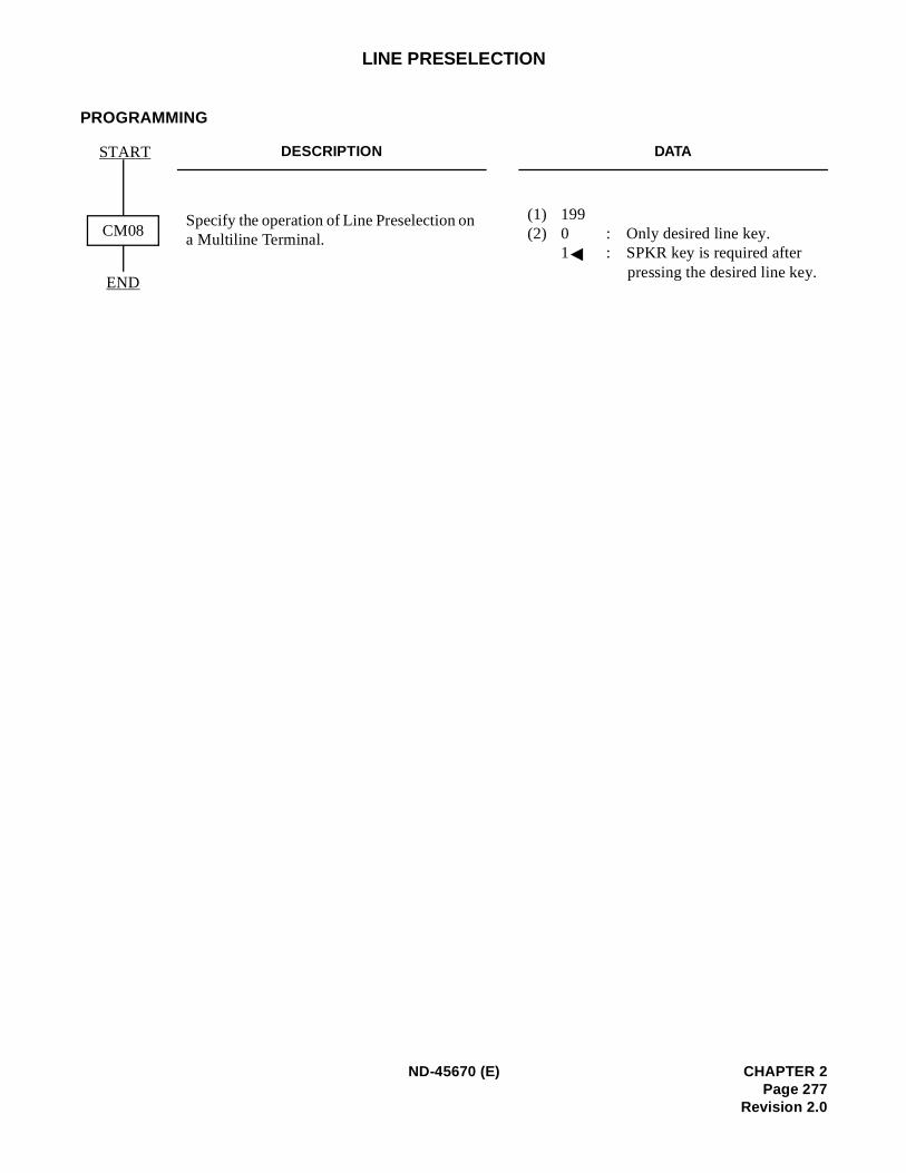
LINE PRESELECTION
PROGRAMMING
DESCRIPTION DATA
Specify the operation of Line Preselection on a Multiline Terminal.
(1) 199 (2) 0 : Only desired line key.
1 : SPKR key is required after pressing the desired line key.
START
END
CM08
ND-45670 (E) CHAPTER 2Page 277
Revision 2.0
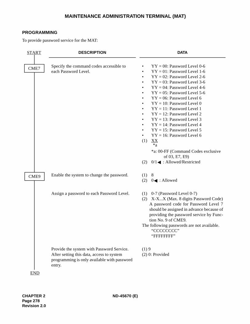
f
MAINTENANCE ADMINISTRATION TERMINAL (MAT)
PROGRAMMING
To provide password service for the MAT:
DESCRIPTION DATA
Specify the command codes accessible to each Password Level.
• YY = 00: Password Level 0-6 • YY = 01: Password Level 1-6 • YY = 02: Password Level 2-6 • YY = 03: Password Level 3-6 • YY = 04: Password Level 4-6 • YY = 05: Password Level 5-6 • YY = 06: Password Level 6 • YY = 10: Password Level 0 • YY = 11: Password Level 1 • YY = 12: Password Level 2 • YY = 13: Password Level 3 • YY = 14: Password Level 4 • YY = 15: Password Level 5 • YY = 16: Password Level 6 (1) XX
*a: 00-FF (Command Codes exclusive of 03, E7, E9)
(2) 0/1 : Allowed/Restricted
Enable the system to change the password. (1) 8 (2) 0 : Allowed
Assign a password to each Password Level. (1) 0-7 (Password Level 0-7)(2) X-X...X (Max. 8 digits Password Code)
A password code for Password Level 7should be assigned in advance because oproviding the password service by Func-tion No. 9 of CME9.
The following passwords are not available. “CCCCCCCC”
“FFFFFFFF”
Provide the system with Password Service. After setting this data, access to system programming is only available with password entry.
(1) 9 (2) 0: Provided
CME7
START
CME9
END
*a
CHAPTER 2 ND-45670 (E)Page 278Revision 2.0
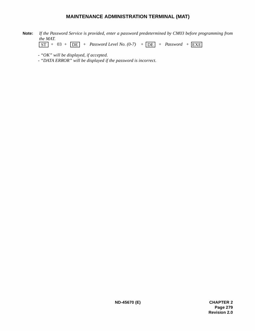
g from
MAINTENANCE ADMINISTRATION TERMINAL (MAT)
Note: If the Password Service is provided, enter a password predetermined by CM03 before programminthe MAT.
+ 03 + + Password Level No. (0-7) + + Password +
- “OK” will be displayed, if accepted. - “DATA ERROR” will be displayed if the password is incorrect.
ST DE DE EXE
ND-45670 (E) CHAPTER 2Page 279
Revision 2.0

MAT: FAULT MESSAGE
PROGRAMMING
Refer to the Maintenance Manual.
CHAPTER 2 ND-45670 (E)Page 280Revision 2.0

MAT: PEG COUNT
PROGRAMMING
Refer to the Command Manual. (Command Code: B0, B3)
ND-45670 (E) CHAPTER 2Page 281
Revision 2.0
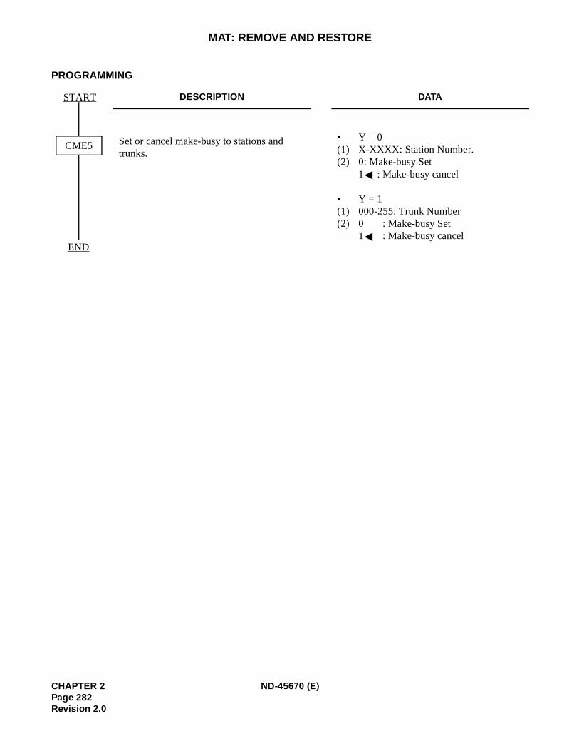
MAT: REMOVE AND RESTORE
PROGRAMMING
DESCRIPTION DATA
Set or cancel make-busy to stations and trunks.
• Y = 0(1) X-XXXX: Station Number. (2) 0: Make-busy Set
1 : Make-busy cancel
• Y = 1(1) 000-255: Trunk Number(2) 0 : Make-busy Set
1 : Make-busy cancel
START
END
CME5
CHAPTER 2 ND-45670 (E)Page 282Revision 2.0

MAT: STATION/TRUNK STATUS
PROGRAMMING
Refer to the Maintenance Manual.
ND-45670 (E) CHAPTER 2Page 283
Revision 2.0

MESSAGE CENTER INTERFACE (MCI)
PROGRAMMING
Refer to the Message Center Interface (MCI) System Manual.
CHAPTER 2 ND-45670 (E)Page 284Revision 2.0
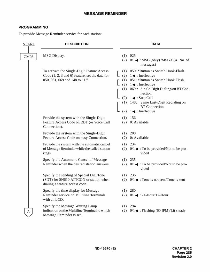
MESSAGE REMINDER
PROGRAMMING
To provide Message Reminder service for each station:
DESCRIPTION DATA
MSG Display. (1) 025(2) 0/1 : MSG (only) /MSGX (X: No. of
messages)
To activate the Single-Digit Feature Access Code (1, 2, 3 and 6) feature, set the data for 050, 051, 069 and 148 to “1.”
(1) 050: *Button as Switch Hook-Flash.(2) 1 : Ineffective(1) 051: #Button as Switch Hook Flash.(2) 1 : Ineffective(1) 069 : Single-Digit Dialing/on BT Con-
nection(2) 1 : Step Call(1) 148: Same Last-Digit Redialing on
BT Connection (2) 1 : Ineffective
Provide the system with the Single-Digit Feature Access Code on RBT (or Voice Call Connection).
(1) 156 (2) 0: Available
Provide the system with the Single-Digit Feature Access Code on busy Connection.
(1) 208 (2) 0: Available
Provide the system with the automatic cancel of Message Reminder while the called station rings.
(1) 234 (2) 0/1 : To be provided/Not to be pro-
vided
Specify the Automatic Cancel of Message Reminder when the desired station answers.
(1) 235 (2) 0/1 : To be provided/Not to be pro-
vided
Specify the sending of Special Dial Tone (SDT) for SN610 ATTCON or station when dialing a feature access code.
(1) 236 (2) 0/1 : Tone is not sent/Tone is sent
Specify the time display for Message Reminder service on Multiline Terminals with an LCD.
(1) 280 (2) 0/1 : 24-Hour/12-Hour
Specify the Message Waiting Lamp indication on the Multiline Terminal to which Message Reminder is set.
(1) 294 (2) 0/1 : Flashing (60 IPM)/Lit steady
CM08
START
A
ND-45670 (E) CHAPTER 2Page 285
Revision 2.0
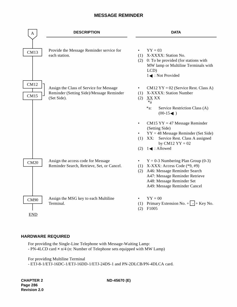
MESSAGE REMINDER
HARDWARE REQUIRED
For providing the Single-Line Telephone with Message-Waiting Lamp:- PN-4LCD card × n/4 (n: Number of Telephone sets equipped with MW Lamp)
For providing Multiline Terminal- ETJ-8-1/ETJ-16DC-1/ETJ-16DD-1/ETJ-24DS-1 and PN-2DLCB/PN-4DLCA card.
DESCRIPTION DATA
Provide the Message Reminder service for each station.
• YY = 03(1) X-XXXX: Station No. (2) 0: To be provided (for stations with
MW lamp or Multiline Terminals with LCD) 1 : Not Provided
Assign the Class of Service for Message Reminder (Setting Side)/Message Reminder (Set Side).
• CM12 YY = 02 (Service Rest. Class A) (1) X-XXXX: Station Number(2) XX XX
*a: Service Restriction Class (A) (00-15 )
• CM15 YY = 47 Message Reminder (Setting Side)
• YY = 48 Message Reminder (Set Side)(1) XX: Service Rest. Class A assigned
by CM12 YY = 02 (2) 1 : Allowed
Assign the access code for Message Reminder Search, Retrieve, Set, or Cancel.
• Y = 0-3 Numbering Plan Group (0-3)(1) X-XXX: Access Code (*9, #9) (2) A46: Message Reminder Search
A47: Message Reminder RetrieveA48: Message Reminder Set A49: Message Reminder Cancel
Assign the MSG key to each Multiline Terminal.
• YY = 00(1) Primary Extension No. + + Key No. (2) F1005
CM13
CM20
END
CM12
CM15
CM90
A
*a
,
CHAPTER 2 ND-45670 (E)Page 286Revision 2.0
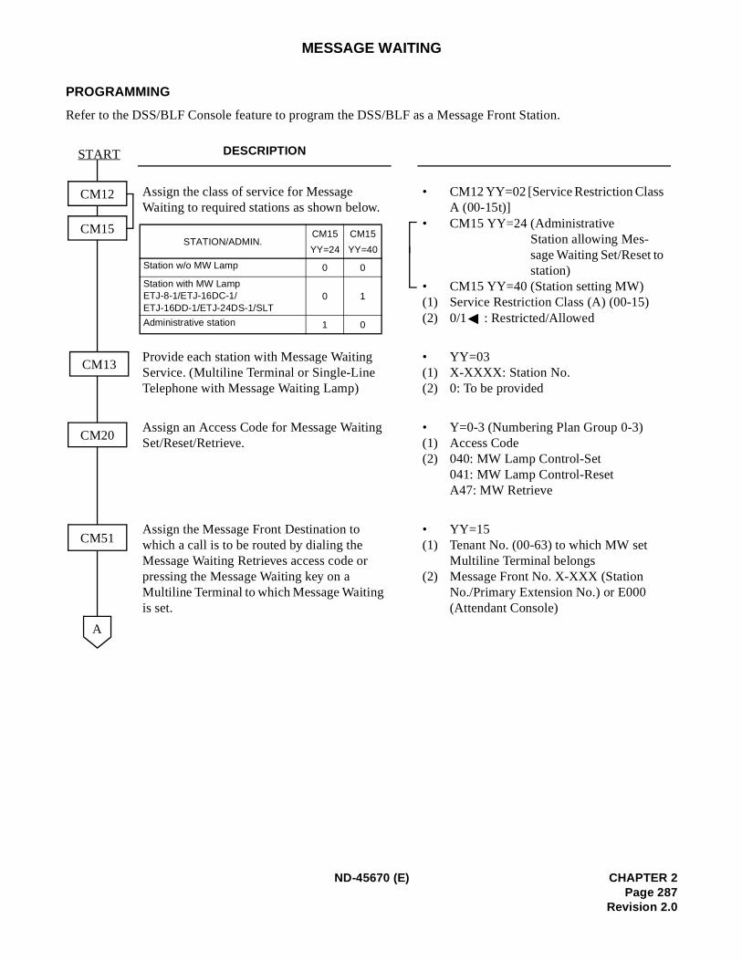
MESSAGE WAITING
PROGRAMMING
Refer to the DSS/BLF Console feature to program the DSS/BLF as a Message Front Station.
DESCRIPTION
Assign the class of service for Message Waiting to required stations as shown below.
• CM12 YY=02 [Service Restriction Class A (00-15t)]
• CM15 YY=24 (AdministrativeStation allowing Mes-sage Waiting Set/Reset to station)
• CM15 YY=40 (Station setting MW) (1) Service Restriction Class (A) (00-15) (2) 0/1 : Restricted/Allowed
Provide each station with Message Waiting Service. (Multiline Terminal or Single-Line Telephone with Message Waiting Lamp)
• YY=03 (1) X-XXXX: Station No. (2) 0: To be provided
Assign an Access Code for Message Waiting Set/Reset/Retrieve.
• Y=0-3 (Numbering Plan Group 0-3) (1) Access Code (2) 040: MW Lamp Control-Set
041: MW Lamp Control-Reset A47: MW Retrieve
Assign the Message Front Destination to which a call is to be routed by dialing the Message Waiting Retrieves access code or pressing the Message Waiting key on a Multiline Terminal to which Message Waiting is set.
• YY=15 (1) Tenant No. (00-63) to which MW set
Multiline Terminal belongs (2) Message Front No. X-XXX (Station
No./Primary Extension No.) or E000 (Attendant Console)
CM12
CM15
CM13
CM20
CM51
A
START
STATION/ADMIN.CM15
YY=24
CM15
YY=40
Station w/o MW Lamp 0 0
Station with MW Lamp ETJ-8-1/ETJ-16DC-1/ETJ-16DD-1/ETJ-24DS-1/SLT
0 1
Administrative station 1 0
ND-45670 (E) CHAPTER 2Page 287
Revision 2.0
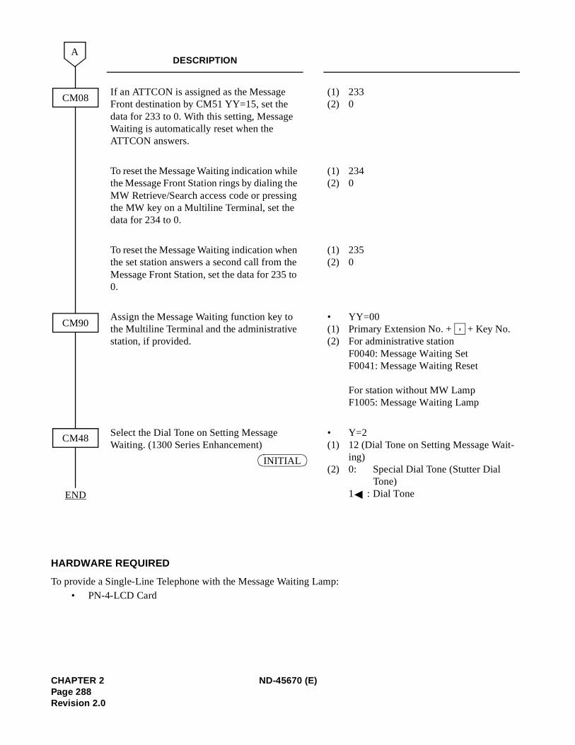
HARDWARE REQUIRED
To provide a Single-Line Telephone with the Message Waiting Lamp:• PN-4-LCD Card
DESCRIPTION
If an ATTCON is assigned as the Message Front destination by CM51 YY=15, set the data for 233 to 0. With this setting, Message Waiting is automatically reset when the ATTCON answers.
(1) 233 (2) 0
To reset the Message Waiting indication while the Message Front Station rings by dialing the MW Retrieve/Search access code or pressing the MW key on a Multiline Terminal, set the data for 234 to 0.
(1) 234 (2) 0
To reset the Message Waiting indication when the set station answers a second call from the Message Front Station, set the data for 235 to 0.
(1) 235 (2) 0
Assign the Message Waiting function key to the Multiline Terminal and the administrative station, if provided.
• YY=00 (1) Primary Extension No. + + Key No. (2) For administrative station
F0040: Message Waiting Set F0041: Message Waiting Reset
For station without MW Lamp F1005: Message Waiting Lamp
Select the Dial Tone on Setting Message Waiting. (1300 Series Enhancement)
• Y=2 (1) 12 (Dial Tone on Setting Message Wait-
ing) (2) 0: Special Dial Tone (Stutter Dial
Tone)1 : Dial Tone
CM08
A
CM90
CM48
END
,
INITIAL
CHAPTER 2 ND-45670 (E)Page 288Revision 2.0
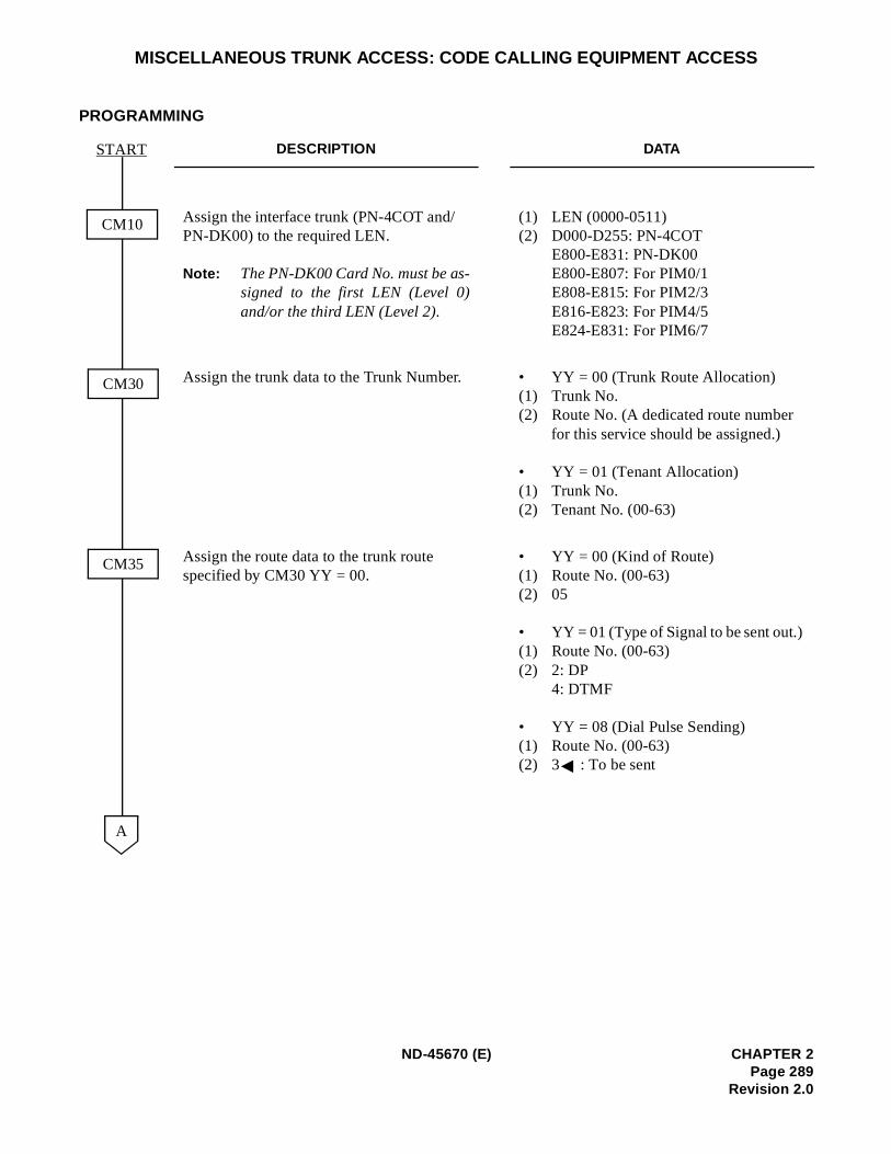
MISCELLANEOUS TRUNK ACCESS: CODE CALLING EQUIPMENT ACCESS
PROGRAMMING
DESCRIPTION DATA
Assign the interface trunk (PN-4COT and/PN-DK00) to the required LEN.
Note: The PN-DK00 Card No. must be as-signed to the first LEN (Level 0)and/or the third LEN (Level 2).
(1) LEN (0000-0511) (2) D000-D255: PN-4COT
E800-E831: PN-DK00E800-E807: For PIM0/1 E808-E815: For PIM2/3 E816-E823: For PIM4/5 E824-E831: For PIM6/7
Assign the trunk data to the Trunk Number. • YY = 00 (Trunk Route Allocation)(1) Trunk No.(2) Route No. (A dedicated route number
for this service should be assigned.)
• YY = 01 (Tenant Allocation)(1) Trunk No.(2) Tenant No. (00-63)
Assign the route data to the trunk route specified by CM30 YY = 00.
• YY = 00 (Kind of Route)(1) Route No. (00-63) (2) 05
• YY = 01 (Type of Signal to be sent out.) (1) Route No. (00-63)(2) 2: DP
4: DTMF
• YY = 08 (Dial Pulse Sending) (1) Route No. (00-63) (2) 3 : To be sent
CM10
START
CM35
CM30
A
ND-45670 (E) CHAPTER 2Page 289
Revision 2.0
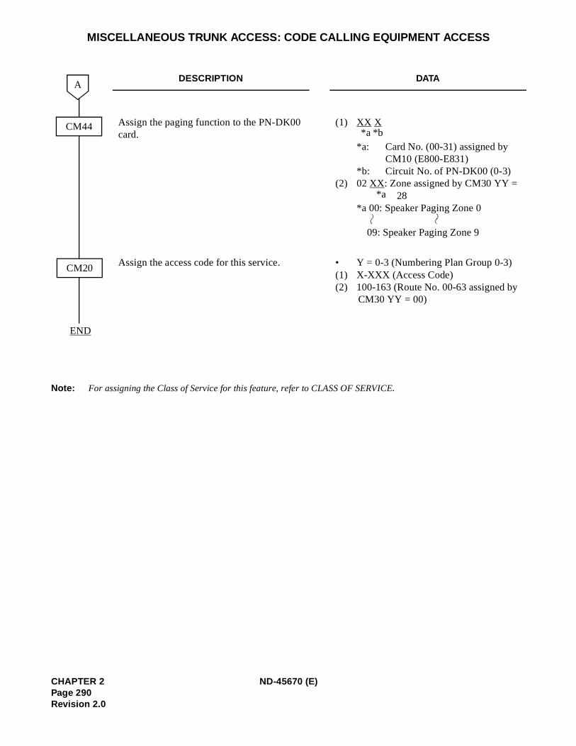
)
MISCELLANEOUS TRUNK ACCESS: CODE CALLING EQUIPMENT ACCESS
Note: For assigning the Class of Service for this feature, refer to CLASS OF SERVICE.
DESCRIPTION DATA
Assign the paging function to the PN-DK00 card.
(1) XX X
*a: Card No. (00-31) assigned by CM10 (E800-E831)
*b: Circuit No. of PN-DK00 (0-3) (2) 02 XX: Zone assigned by CM30 YY = 28
*a 00: Speaker Paging Zone 0
09: Speaker Paging Zone 9
Assign the access code for this service. • Y = 0-3 (Numbering Plan Group 0-3(1) X-XXX (Access Code)(2) 100-163 (Route No. 00-63 assigned by
CM30 YY = 00)
CM44
END
CM20
A
*b*a
*a
CHAPTER 2 ND-45670 (E)Page 290Revision 2.0
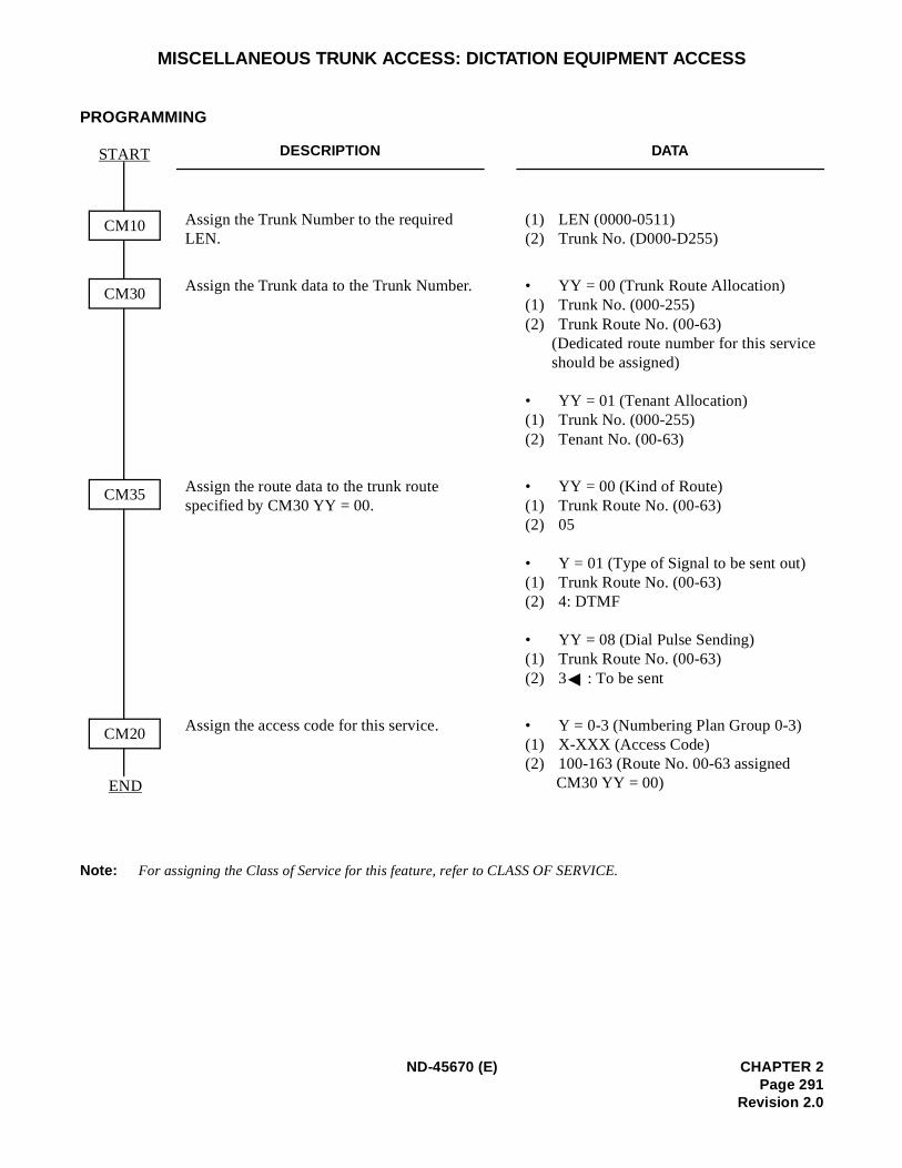
)
MISCELLANEOUS TRUNK ACCESS: DICTATION EQUIPMENT ACCESS
PROGRAMMING
Note: For assigning the Class of Service for this feature, refer to CLASS OF SERVICE.
DESCRIPTION DATA
Assign the Trunk Number to the required LEN.
(1) LEN (0000-0511) (2) Trunk No. (D000-D255)
Assign the Trunk data to the Trunk Number. • YY = 00 (Trunk Route Allocation)(1) Trunk No. (000-255)(2) Trunk Route No. (00-63)
(Dedicated route number for this serviceshould be assigned)
• YY = 01 (Tenant Allocation)(1) Trunk No. (000-255)(2) Tenant No. (00-63)
Assign the route data to the trunk route specified by CM30 YY = 00.
• YY = 00 (Kind of Route)(1) Trunk Route No. (00-63)(2) 05
• Y = 01 (Type of Signal to be sent out) (1) Trunk Route No. (00-63) (2) 4: DTMF
• YY = 08 (Dial Pulse Sending) (1) Trunk Route No. (00-63)(2) 3 : To be sent
Assign the access code for this service. • Y = 0-3 (Numbering Plan Group 0-3(1) X-XXX (Access Code) (2) 100-163 (Route No. 00-63 assigned
CM30 YY = 00)
CM30
START
CM35
CM20
CM10
END
ND-45670 (E) CHAPTER 2Page 291
Revision 2.0
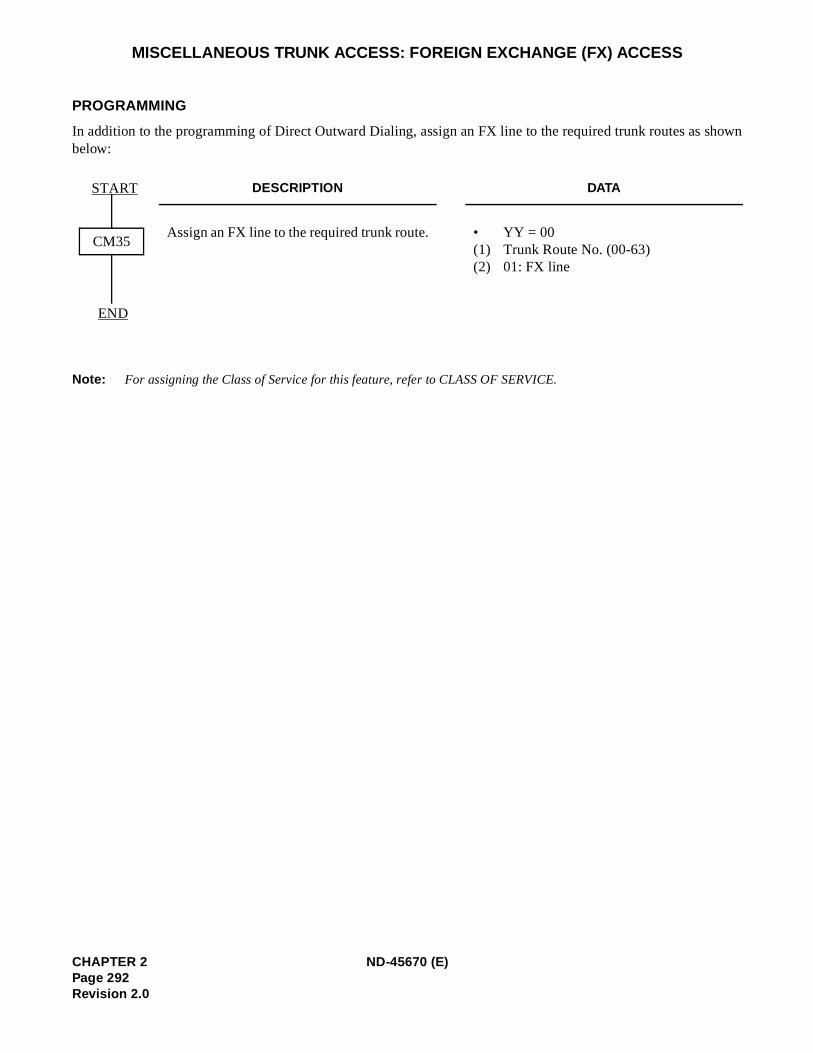
shown
MISCELLANEOUS TRUNK ACCESS: FOREIGN EXCHANGE (FX) ACCESS
PROGRAMMING
In addition to the programming of Direct Outward Dialing, assign an FX line to the required trunk routes as below:
Note: For assigning the Class of Service for this feature, refer to CLASS OF SERVICE.
DESCRIPTION DATA
Assign an FX line to the required trunk route. • YY = 00 (1) Trunk Route No. (00-63) (2) 01: FX line
CM35
START
END
CHAPTER 2 ND-45670 (E)Page 292Revision 2.0
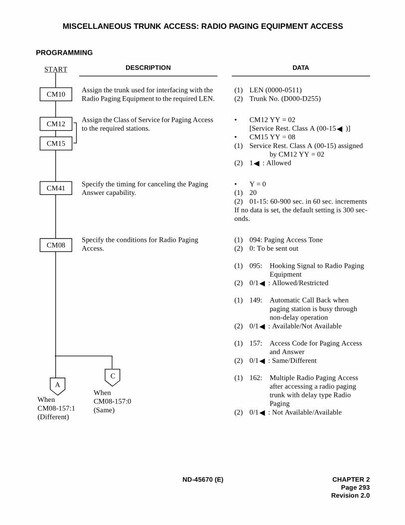
sc-
MISCELLANEOUS TRUNK ACCESS: RADIO PAGING EQUIPMENT ACCESS
PROGRAMMING
DESCRIPTION DATA
Assign the trunk used for interfacing with the Radio Paging Equipment to the required LEN.
(1) LEN (0000-0511)(2) Trunk No. (D000-D255)
Assign the Class of Service for Paging Access to the required stations.
• CM12 YY = 02[Service Rest. Class A (00-15 )]
• CM15 YY = 08(1) Service Rest. Class A (00-15) assigned
by CM12 YY = 02(2) 1 : Allowed
Specify the timing for canceling the Paging Answer capability.
• Y = 0(1) 20(2) 01-15: 60-900 sec. in 60 sec. incrementIf no data is set, the default setting is 300 seonds.
Specify the conditions for Radio Paging Access.
(1) 094: Paging Access Tone(2) 0: To be sent out
(1) 095: Hooking Signal to Radio Paging Equipment
(2) 0/1 : Allowed/Restricted
(1) 149: Automatic Call Back when paging station is busy through non-delay operation
(2) 0/1 : Available/Not Available
(1) 157: Access Code for Paging Access and Answer
(2) 0/1 : Same/Different
(1) 162: Multiple Radio Paging Access after accessing a radio paging trunk with delay type Radio Paging
(2) 0/1 : Not Available/Available
CM08
START
CM41
CM10
CM12
CM15
A
WhenCM08-157:1(Different)
C
WhenCM08-157:0(Same)
ND-45670 (E) CHAPTER 2Page 293
Revision 2.0
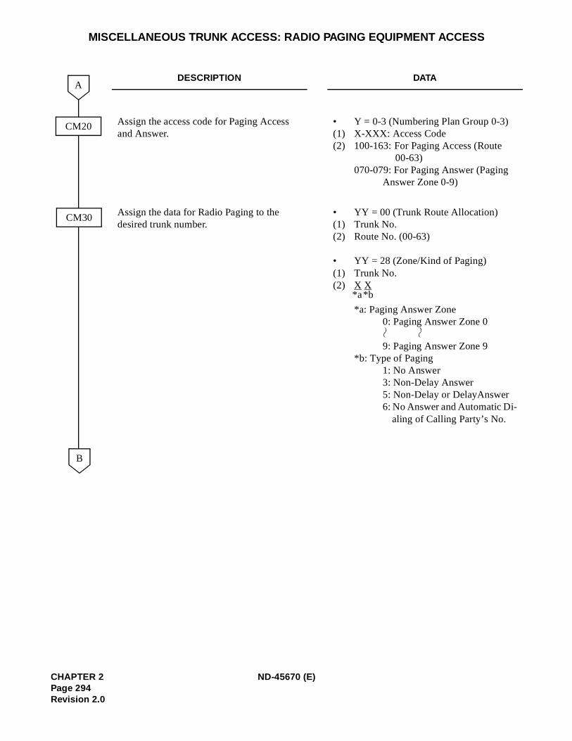
MISCELLANEOUS TRUNK ACCESS: RADIO PAGING EQUIPMENT ACCESS
DESCRIPTION DATA
Assign the access code for Paging Access and Answer.
• Y = 0-3 (Numbering Plan Group 0-3) (1) X-XXX: Access Code(2) 100-163: For Paging Access (Route
00-63)070-079: For Paging Answer (Paging
Answer Zone 0-9)
Assign the data for Radio Paging to the desired trunk number.
• YY = 00 (Trunk Route Allocation) (1) Trunk No. (2) Route No. (00-63)
• YY = 28 (Zone/Kind of Paging)(1) Trunk No. (2) X X
*a: Paging Answer Zone0: Paging Answer Zone 0
9: Paging Answer Zone 9*b: Type of Paging
1: No Answer3: Non-Delay Answer 5: Non-Delay or DelayAnswer 6: No Answer and Automatic Di-
aling of Calling Party’s No.
CM20
CM30
B
A
*b*a
CHAPTER 2 ND-45670 (E)Page 294Revision 2.0
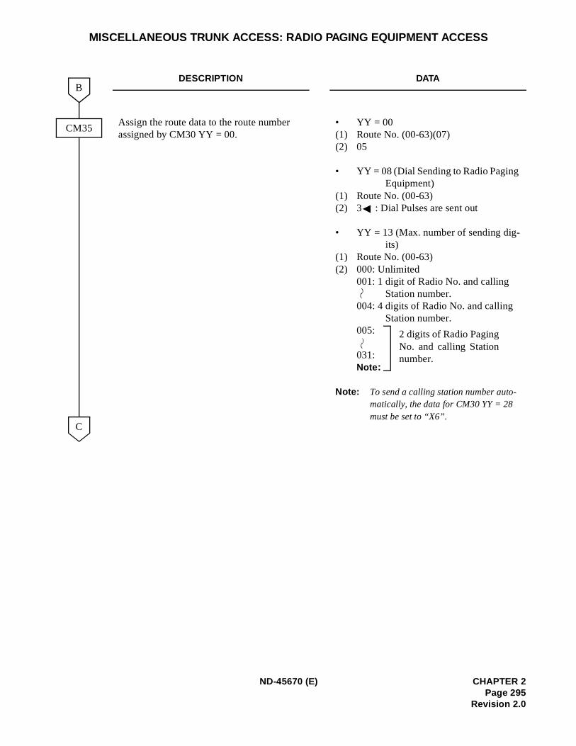
MISCELLANEOUS TRUNK ACCESS: RADIO PAGING EQUIPMENT ACCESS
DESCRIPTION DATA
Assign the route data to the route number assigned by CM30 YY = 00.
• YY = 00(1) Route No. (00-63)(07)(2) 05
• YY = 08 (Dial Sending to Radio Paging Equipment)
(1) Route No. (00-63)(2) 3 : Dial Pulses are sent out
• YY = 13 (Max. number of sending dig-its)
(1) Route No. (00-63)(2) 000: Unlimited
001: 1 digit of Radio No. and calling Station number.
004: 4 digits of Radio No. and calling Station number.
005:
031:Note :
Note: To send a calling station number auto-matically, the data for CM30 YY = 28 must be set to “X6”.
CM35
B
C
2 digits of Radio PagingNo. and calling Stationnumber.
ND-45670 (E) CHAPTER 2Page 295
Revision 2.0
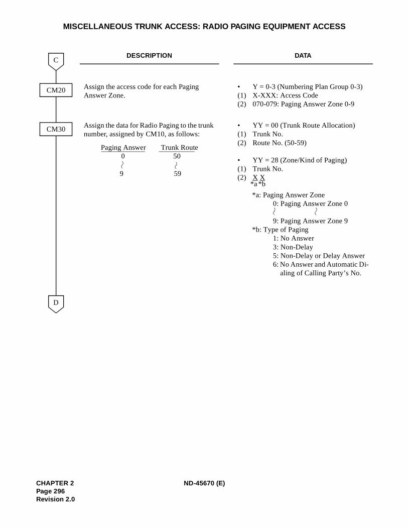
MISCELLANEOUS TRUNK ACCESS: RADIO PAGING EQUIPMENT ACCESS
DESCRIPTION DATA
Assign the access code for each Paging Answer Zone.
• Y = 0-3 (Numbering Plan Group 0-3) (1) X-XXX: Access Code(2) 070-079: Paging Answer Zone 0-9
Assign the data for Radio Paging to the trunk number, assigned by CM10, as follows:
• YY = 00 (Trunk Route Allocation) (1) Trunk No. (2) Route No. (50-59)
• YY = 28 (Zone/Kind of Paging)(1) Trunk No. (2) X X
*a: Paging Answer Zone0: Paging Answer Zone 0
9: Paging Answer Zone 9 *b: Type of Paging
1: No Answer 3: Non-Delay5: Non-Delay or Delay Answer6: No Answer and Automatic Di-
aling of Calling Party’s No.
CM20
C
D
CM30
Paging Answer Trunk Route 0 50
9 59
*b*a
CHAPTER 2 ND-45670 (E)Page 296Revision 2.0
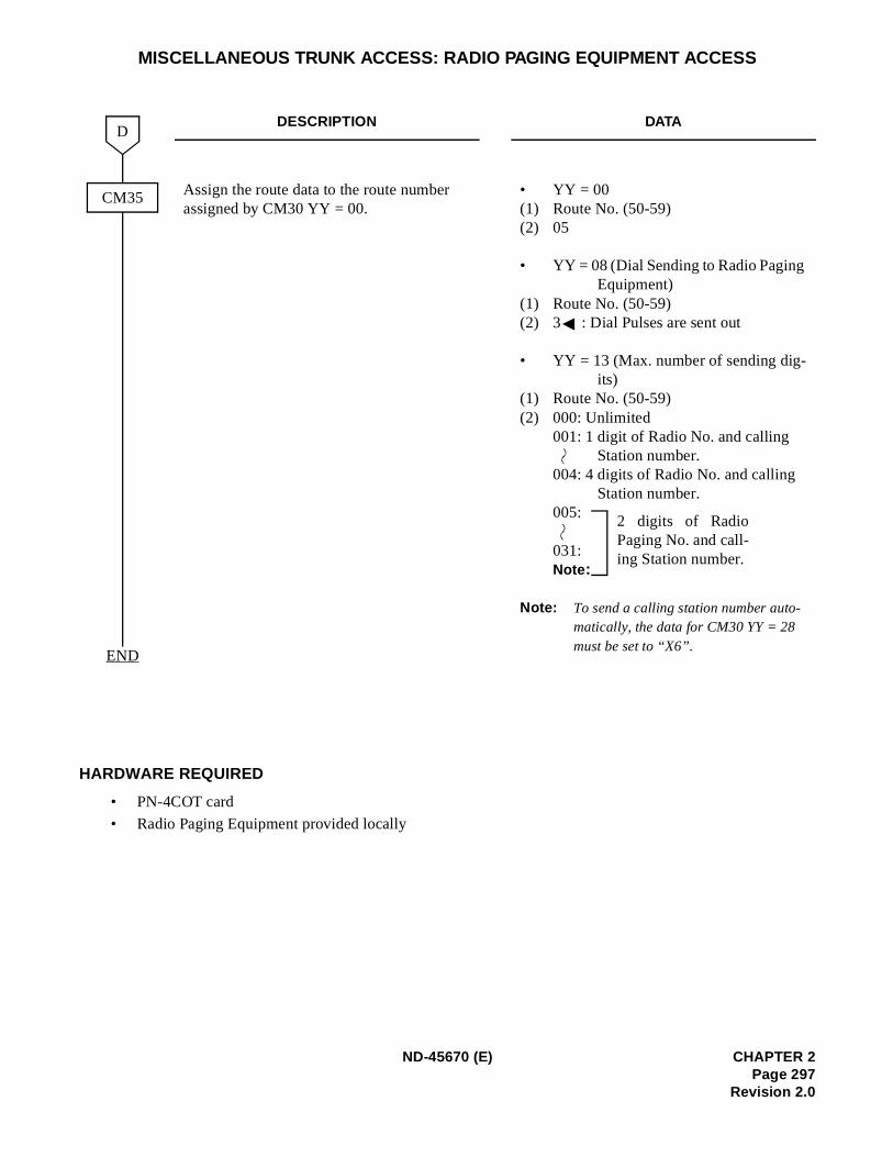
MISCELLANEOUS TRUNK ACCESS: RADIO PAGING EQUIPMENT ACCESS
HARDWARE REQUIRED
• PN-4COT card
• Radio Paging Equipment provided locally
DESCRIPTION DATA
Assign the route data to the route number assigned by CM30 YY = 00.
• YY = 00(1) Route No. (50-59)(2) 05
• YY = 08 (Dial Sending to Radio Paging Equipment)
(1) Route No. (50-59)(2) 3 : Dial Pulses are sent out
• YY = 13 (Max. number of sending dig-its)
(1) Route No. (50-59)(2) 000: Unlimited
001: 1 digit of Radio No. and calling Station number.
004: 4 digits of Radio No. and calling Station number.
005:
031:Note :
Note: To send a calling station number auto-matically, the data for CM30 YY = 28 must be set to “X6”.
D
END
CM35
2 digits of RadioPaging No. and call-ing Station number.
ND-45670 (E) CHAPTER 2Page 297
Revision 2.0
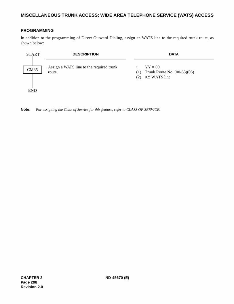
te, as
MISCELLANEOUS TRUNK ACCESS: WIDE AREA TELEPHONE SERVICE (WATS) ACCESS
PROGRAMMING
In addition to the programming of Direct Outward Dialing, assign an WATS line to the required trunk roushown below:
Note: For assigning the Class of Service for this feature, refer to CLASS OF SERVICE.
DESCRIPTION DATA
Assign a WATS line to the required trunk route.
• YY = 00 (1) Trunk Route No. (00-63)(05) (2) 02: WATS line
CM35
START
END
CHAPTER 2 ND-45670 (E)Page 298Revision 2.0
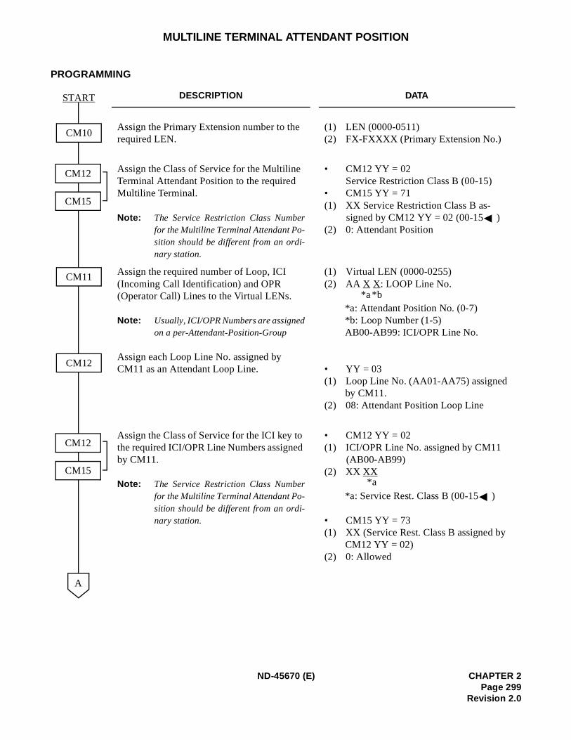
MULTILINE TERMINAL ATTENDANT POSITION
PROGRAMMING
DESCRIPTION DATA
Assign the Primary Extension number to the required LEN.
(1) LEN (0000-0511) (2) FX-FXXXX (Primary Extension No.)
Assign the Class of Service for the Multiline Terminal Attendant Position to the required Multiline Terminal.
Note: The Service Restriction Class Numberfor the Multiline Terminal Attendant Po-sition should be different from an ordi-nary station.
• CM12 YY = 02 Service Restriction Class B (00-15)
• CM15 YY = 71 (1) XX Service Restriction Class B as-
signed by CM12 YY = 02 (00-15 )(2) 0: Attendant Position
Assign the required number of Loop, ICI (Incoming Call Identification) and OPR (Operator Call) Lines to the Virtual LENs.
Note: Usually, ICI/OPR Numbers are assignedon a per-Attendant-Position-Group
Assign each Loop Line No. assigned by CM11 as an Attendant Loop Line.
(1) Virtual LEN (0000-0255) (2) AA X X: LOOP Line No.
*a: Attendant Position No. (0-7) *b: Loop Number (1-5) AB00-AB99: ICI/OPR Line No.
• YY = 03(1) Loop Line No. (AA01-AA75) assigned
by CM11.(2) 08: Attendant Position Loop Line
Assign the Class of Service for the ICI key to the required ICI/OPR Line Numbers assigned by CM11.
Note: The Service Restriction Class Numberfor the Multiline Terminal Attendant Po-sition should be different from an ordi-nary station.
• CM12 YY = 02 (1) ICI/OPR Line No. assigned by CM11
(AB00-AB99) (2) XX XX
*a: Service Rest. Class B (00-15 )
• CM15 YY = 73 (1) XX (Service Rest. Class B assigned by
CM12 YY = 02) (2) 0: Allowed
CM10
CM12
CM15
START
CM12
A
CM11
CM12
CM15
*b*a
*a
ND-45670 (E) CHAPTER 2Page 299
Revision 2.0
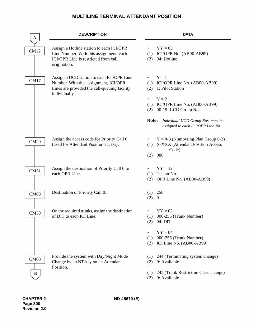
MULTILINE TERMINAL ATTENDANT POSITION
DESCRIPTION DATA
Assign a Hotline station to each ICI/OPR Line Number. With this assignment, each ICI/OPR Line is restricted from call origination.
• YY = 03(1) ICI/OPR No. (AB00-AB99)(2) 04: Hotline
Assign a UCD station to each ICI/OPR Line Number. With this assignment, ICI/OPR Lines are provided the call-queuing facility individually.
• Y = 1(1) ICI/OPR Line No. (AB00-AB99) (2) 1: Pilot Station
• Y = 2(1) ICI/OPR Line No. (AB00-AB99) (2) 00-15: UCD Group No.
Note: Individual UCD Group Nos. must be assigned to each ICI/OPR Line No.
Assign the access code for Priority Call 0 (used for Attendant Position access).
• Y = 0-3 (Numbering Plan Group 0-3) (1) X-XXX (Attendant Position Access
Code)(2) 088
Assign the destination of Priority Call 0 to each OPR Line.
• YY = 12(1) Tenant No.(2) OPR Line No. (AB00-AB99)
Destination of Priority Call 0. (1) 250 (2) 0
On the required trunks, assign the destination of DIT to each ICI Line.
• YY = 02(1) 000-255 (Trunk Number)(2) 04: DIT
• YY = 04(1) 000-255 (Trunk Number)(2) ICI Line No. (AB00-AB99)
Provide the system with Day/Night Mode Change by an NT key on an Attendant Position.
(1) 244 (Terminating system change) (2) 0: Available
(1) 245 (Trunk Restriction Class change)(2) 0: Available
CM12
CM17
B
A
CM20
CM30
CM08
CM51
CM08
CHAPTER 2 ND-45670 (E)Page 300Revision 2.0
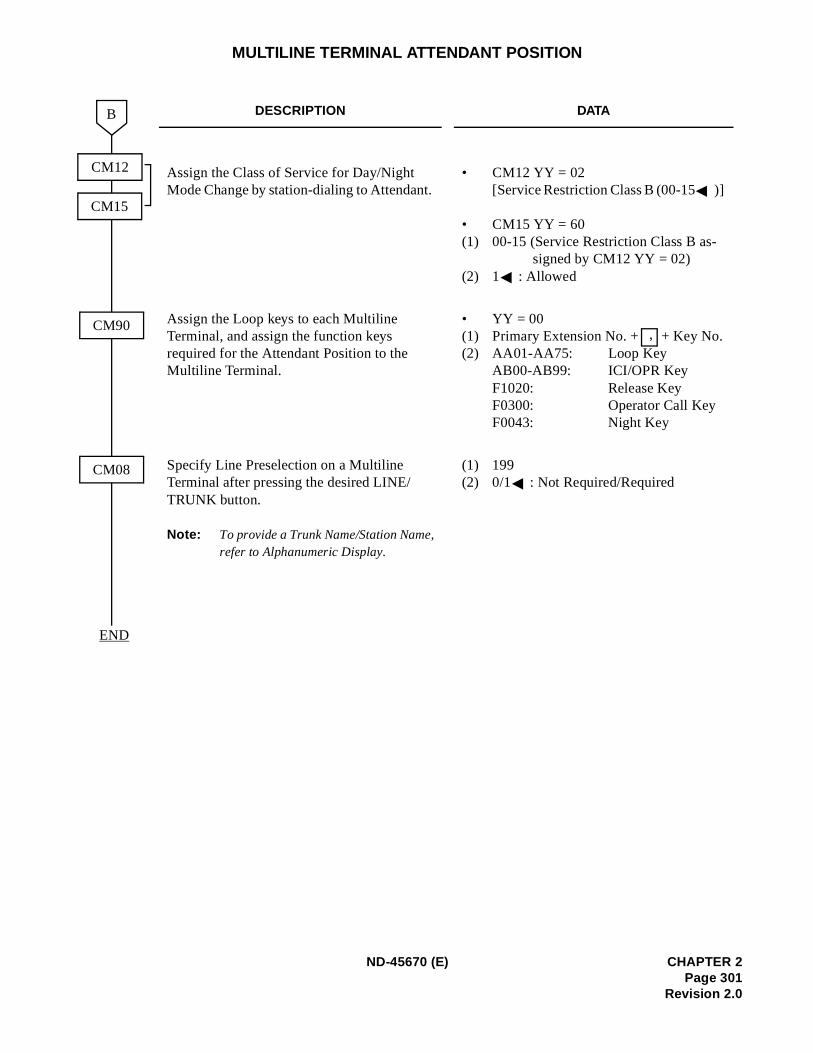
MULTILINE TERMINAL ATTENDANT POSITION
DESCRIPTION DATA
Assign the Class of Service for Day/Night Mode Change by station-dialing to Attendant.
• CM12 YY = 02 [Service Restriction Class B (00-15 )]
• CM15 YY = 60 (1) 00-15 (Service Restriction Class B as-
signed by CM12 YY = 02)(2) 1 : Allowed
Assign the Loop keys to each Multiline Terminal, and assign the function keys required for the Attendant Position to the Multiline Terminal.
• YY = 00 (1) Primary Extension No. + + Key No. (2) AA01-AA75: Loop Key
AB00-AB99: ICI/OPR KeyF1020: Release KeyF0300: Operator Call KeyF0043: Night Key
Specify Line Preselection on a Multiline Terminal after pressing the desired LINE/TRUNK button.
Note: To provide a Trunk Name/Station Name,refer to Alphanumeric Display.
(1) 199 (2) 0/1 : Not Required/Required
B
CM90
CM08
CM12
CM15
END
,
ND-45670 (E) CHAPTER 2Page 301
Revision 2.0
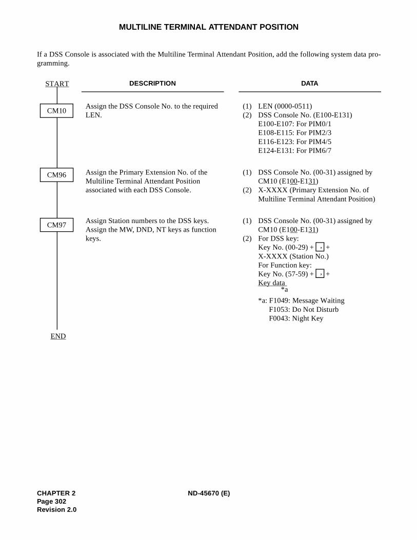
ta pro-
MULTILINE TERMINAL ATTENDANT POSITION
If a DSS Console is associated with the Multiline Terminal Attendant Position, add the following system dagramming.
DESCRIPTION DATA
Assign the DSS Console No. to the required LEN.
(1) LEN (0000-0511) (2) DSS Console No. (E100-E131)
E100-E107: For PIM0/1 E108-E115: For PIM2/3 E116-E123: For PIM4/5 E124-E131: For PIM6/7
Assign the Primary Extension No. of the Multiline Terminal Attendant Position associated with each DSS Console.
(1) DSS Console No. (00-31) assigned by CM10 (E100-E131)(2) X-XXXX (Primary Extension No. of
Multiline Terminal Attendant Position)
Assign Station numbers to the DSS keys. Assign the MW, DND, NT keys as function keys.
(1) DSS Console No. (00-31) assigned byCM10 (E100-E131)
(2) For DSS key: Key No. (00-29) + + X-XXXX (Station No.)For Function key: Key No. (57-59) + +Key data
*a: F1049: Message WaitingF1053: Do Not Disturb F0043: Night Key
CM10
CM96
START
END
CM97
,
,
*a
CHAPTER 2 ND-45670 (E)Page 302Revision 2.0
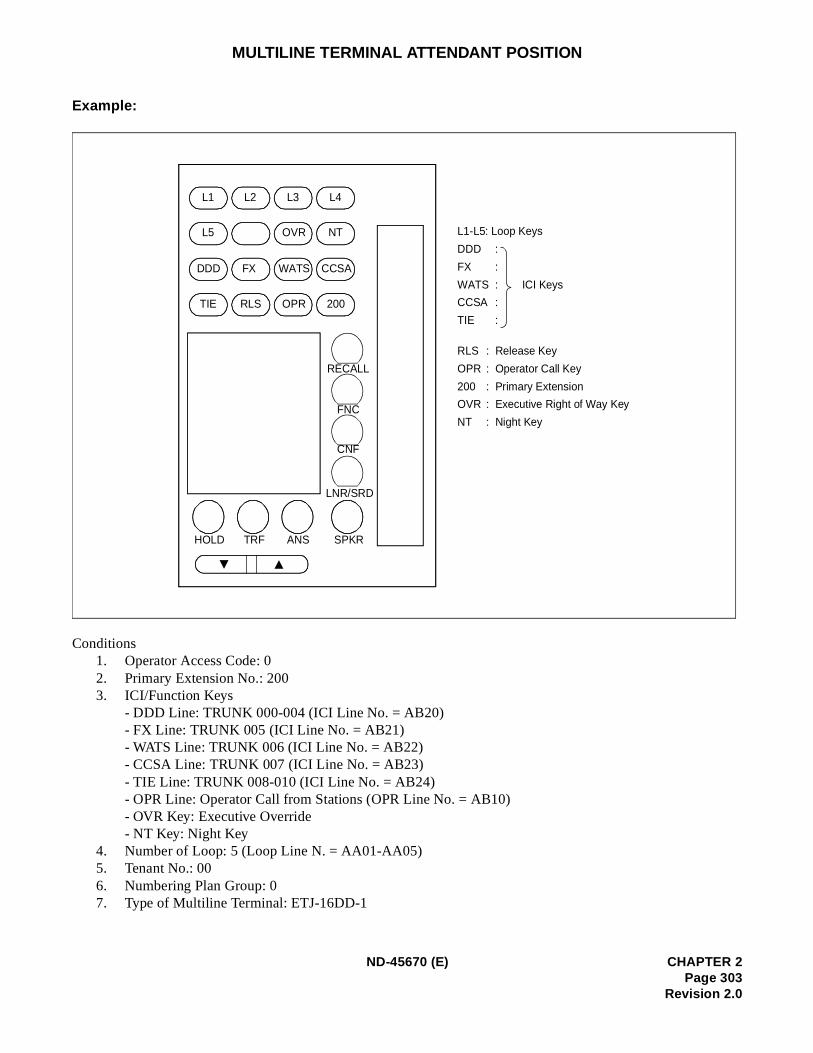
MULTILINE TERMINAL ATTENDANT POSITION
Example:
Conditions1. Operator Access Code: 02. Primary Extension No.: 200 3. ICI/Function Keys
- DDD Line: TRUNK 000-004 (ICI Line No. = AB20)- FX Line: TRUNK 005 (ICI Line No. = AB21) - WATS Line: TRUNK 006 (ICI Line No. = AB22) - CCSA Line: TRUNK 007 (ICI Line No. = AB23) - TIE Line: TRUNK 008-010 (ICI Line No. = AB24)- OPR Line: Operator Call from Stations (OPR Line No. = AB10)- OVR Key: Executive Override- NT Key: Night Key
4. Number of Loop: 5 (Loop Line N. = AA01-AA05) 5. Tenant No.: 00 6. Numbering Plan Group: 07. Type of Multiline Terminal: ETJ-16DD-1
:
:
:
:
:
L1 L2 L3 L4
L5 OVR NT
DDD FX WATS CCSA
TIE RLS OPR 200
RECALL
FNC
CNF
LNR/SRD
SPKRANSTRFHOLD
L1-L5: Loop Keys
DDD
FX
WATS ICI Keys
CCSA
TIE
RLS
OPR
200
OVR
NT
: Release Key
: Operator Call Key
: Primary Extension
: Executive Right of Way Key
: Night Key
ND-45670 (E) CHAPTER 2Page 303
Revision 2.0
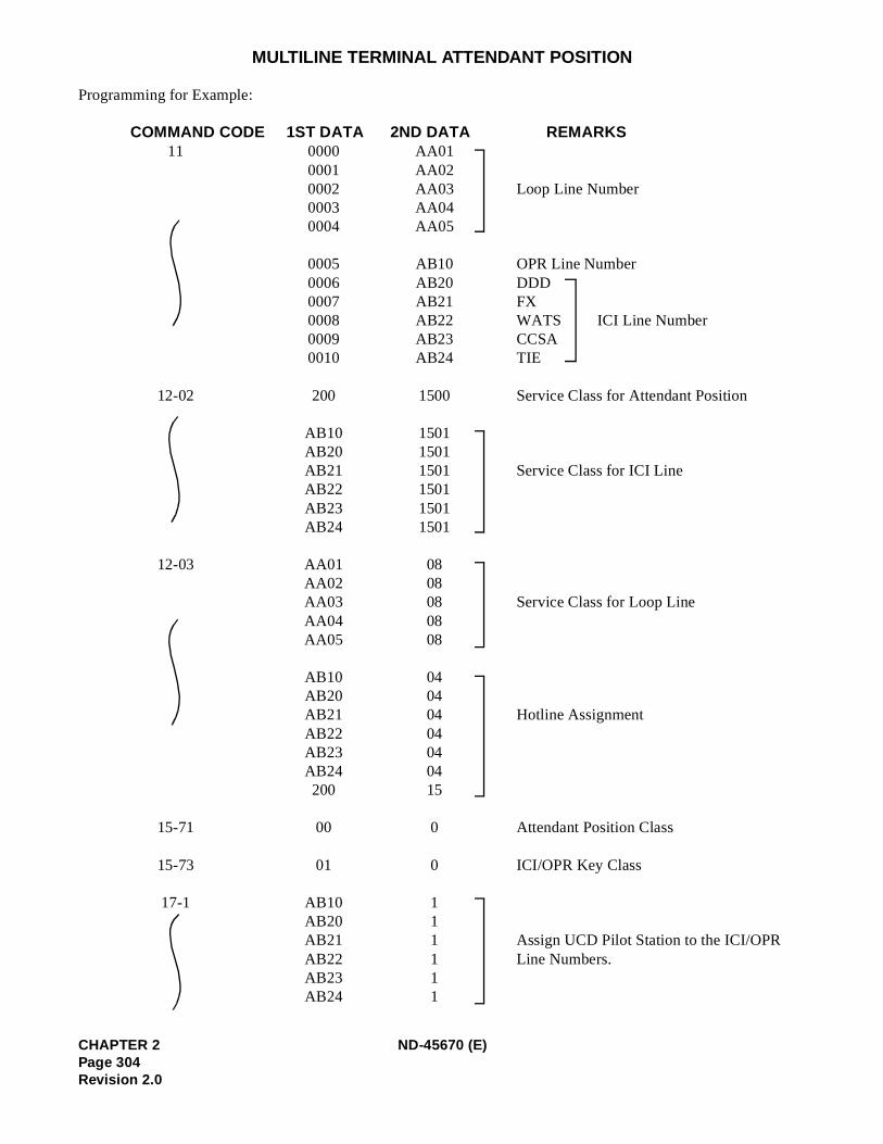
MULTILINE TERMINAL ATTENDANT POSITION
Programming for Example:
COMMAND CODE 1ST DATA 2ND DATA REMARKS 11 0000 AA01
0001 AA020002 AA03 Loop Line Number0003 AA040004 AA05
0005 AB10 OPR Line Number 0006 AB20 DDD 0007 AB21 FX 0008 AB22 WATS ICI Line Number0009 AB23 CCSA0010 AB24 TIE
12-02 200 1500 Service Class for Attendant Position
AB10 1501AB20 1501 AB21 1501 Service Class for ICI LineAB22 1501AB23 1501AB24 1501
12-03 AA01 08AA02 08AA03 08 Service Class for Loop LineAA04 08AA05 08
AB10 04AB20 04AB21 04 Hotline AssignmentAB22 04AB23 04AB24 04200 15
15-71 00 0 Attendant Position Class
15-73 01 0 ICI/OPR Key Class
17-1 AB10 1AB20 1AB21 1 Assign UCD Pilot Station to the ICI/OPR
AB22 1 Line Numbers. AB23 1AB24 1
CHAPTER 2 ND-45670 (E)Page 304Revision 2.0
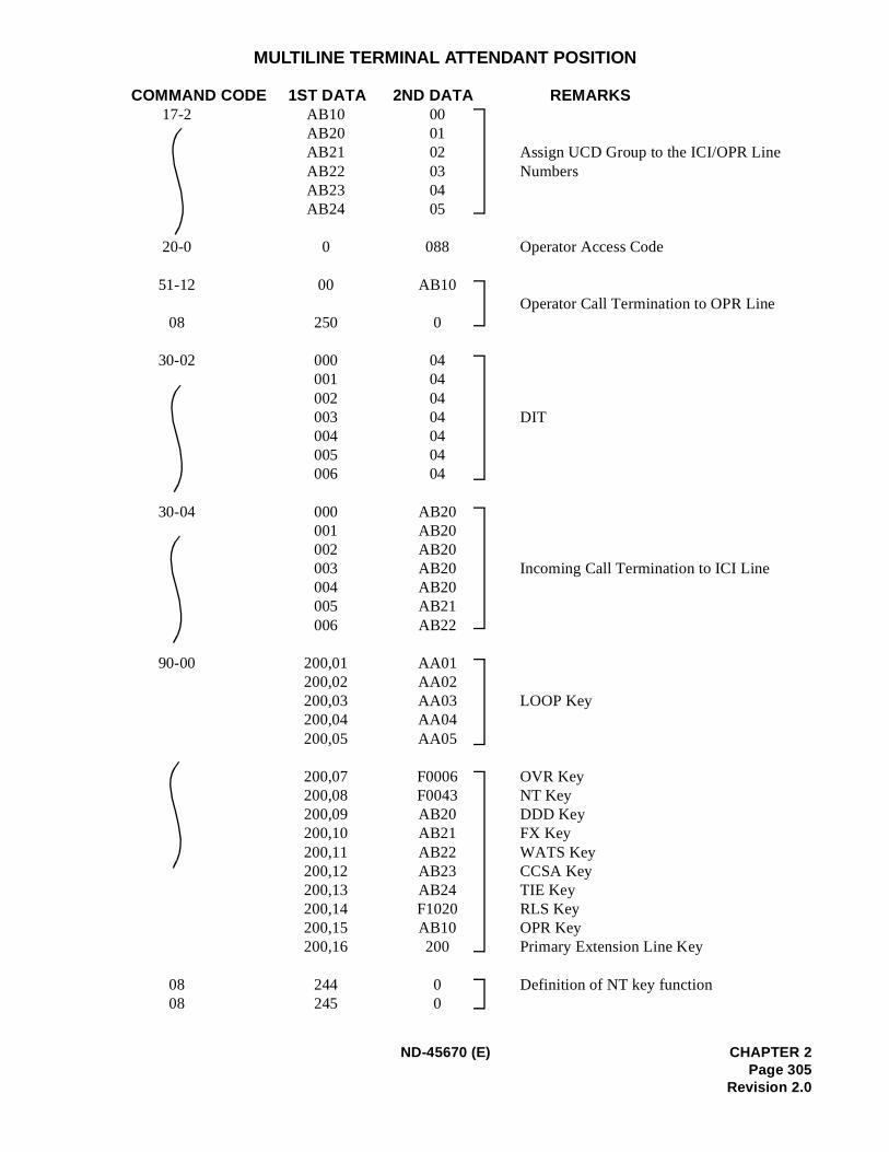
MULTILINE TERMINAL ATTENDANT POSITION
COMMAND CODE 1ST DATA 2ND DATA REMARKS 17-2 AB10 00
AB20 01AB21 02 Assign UCD Group to the ICI/OPR Line
AB22 03 NumbersAB23 04AB24 05
20-0 0 088 Operator Access Code
51-12 00 AB10Operator Call Termination to OPR Line
08 250 0
30-02 000 04001 04002 04003 04 DIT 004 04005 04006 04
30-04 000 AB20001 AB20002 AB20003 AB20 Incoming Call Termination to ICI Line 004 AB20005 AB21006 AB22
90-00 200,01 AA01200,02 AA02200,03 AA03 LOOP Key200,04 AA04200,05 AA05
200,07 F0006 OVR Key 200,08 F0043 NT Key200,09 AB20 DDD Key 200,10 AB21 FX Key200,11 AB22 WATS Key200,12 AB23 CCSA Key200,13 AB24 TIE Key 200,14 F1020 RLS Key200,15 AB10 OPR Key200,16 200 Primary Extension Line Key
08 244 0 Definition of NT key function 08 245 0
ND-45670 (E) CHAPTER 2Page 305
Revision 2.0
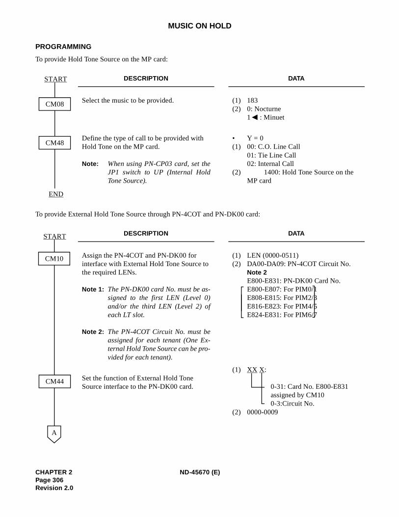
MUSIC ON HOLD
PROGRAMMING
To provide Hold Tone Source on the MP card:
To provide External Hold Tone Source through PN-4COT and PN-DK00 card:
DESCRIPTION DATA
Select the music to be provided. (1) 183 (2) 0: Nocturne
1 : Minuet
Define the type of call to be provided with Hold Tone on the MP card.
Note: When using PN-CP03 card, set theJP1 switch to UP (Internal HoldTone Source).
• Y = 0(1) 00: C.O. Line Call
01: Tie Line Call 02: Internal Call
(2) 1400: Hold Tone Source on the MP card
DESCRIPTION DATA
Assign the PN-4COT and PN-DK00 for interface with External Hold Tone Source to the required LENs.
Note 1: The PN-DK00 card No. must be as-signed to the first LEN (Level 0)and/or the third LEN (Level 2) ofeach LT slot.
Note 2: The PN-4COT Circuit No. must beassigned for each tenant (One Ex-ternal Hold Tone Source can be pro-vided for each tenant).
(1) LEN (0000-0511)(2) DA00-DA09: PN-4COT Circuit No.
Note 2E800-E831: PN-DK00 Card No.E800-E807: For PIM0/1E808-E815: For PIM2/3E816-E823: For PIM4/5E824-E831: For PIM6/7
Set the function of External Hold Tone Source interface to the PN-DK00 card.
(1) XX X:
0-31: Card No. E800-E831 assigned by CM100-3:Circuit No.
(2) 0000-0009
CM08
START
END
CM48
CM10
START
CM44
A
CHAPTER 2 ND-45670 (E)Page 306Revision 2.0
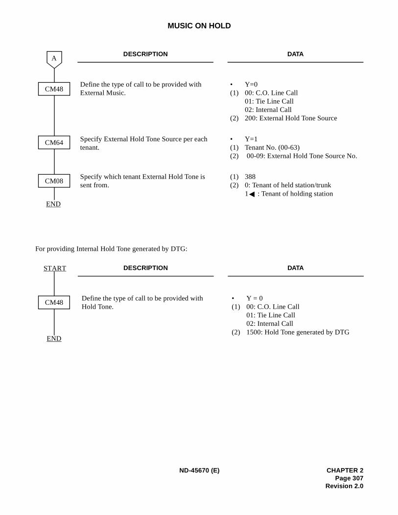
MUSIC ON HOLD
For providing Internal Hold Tone generated by DTG:
DESCRIPTION DATA
Define the type of call to be provided with External Music.
• Y=0(1) 00: C.O. Line Call
01: Tie Line Call02: Internal Call
(2) 200: External Hold Tone Source
Specify External Hold Tone Source per each tenant.
• Y=1(1) Tenant No. (00-63)(2) 00-09: External Hold Tone Source No.
Specify which tenant External Hold Tone is sent from.
(1) 388(2) 0: Tenant of held station/trunk
1 : Tenant of holding station
DESCRIPTION DATA
Define the type of call to be provided with Hold Tone.
• Y = 0(1) 00: C.O. Line Call
01: Tie Line Call 02: Internal Call
(2) 1500: Hold Tone generated by DTG
END
CM48
A
CM64
CM08
CM48
START
END
ND-45670 (E) CHAPTER 2Page 307
Revision 2.0
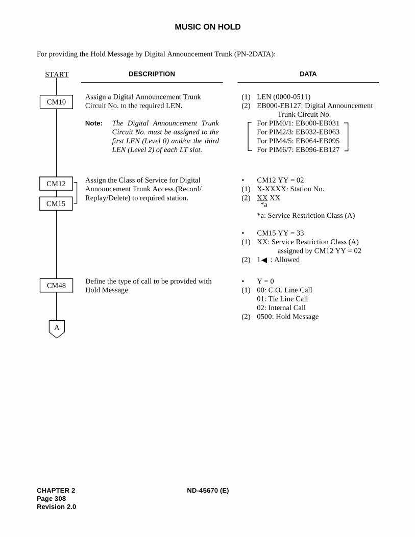
MUSIC ON HOLD
For providing the Hold Message by Digital Announcement Trunk (PN-2DATA):
DESCRIPTION DATA
Assign a Digital Announcement Trunk Circuit No. to the required LEN.
Note: The Digital Announcement TrunkCircuit No. must be assigned to thefirst LEN (Level 0) and/or the thirdLEN (Level 2) of each LT slot.
(1) LEN (0000-0511)(2) EB000-EB127: Digital Announcement
Trunk Circuit No.For PIM0/1: EB000-EB031 For PIM2/3: EB032-EB063 For PIM4/5: EB064-EB095 For PIM6/7: EB096-EB127
Assign the Class of Service for Digital Announcement Trunk Access (Record/Replay/Delete) to required station.
• CM12 YY = 02 (1) X-XXXX: Station No.(2) XX XX
*a: Service Restriction Class (A)
• CM15 YY = 33 (1) XX: Service Restriction Class (A)
assigned by CM12 YY = 02(2) 1 : Allowed
Define the type of call to be provided with Hold Message.
• Y = 0(1) 00: C.O. Line Call
01: Tie Line Call 02: Internal Call
(2) 0500: Hold Message
CM10
START
CM48
CM12
CM15
A
*a
CHAPTER 2 ND-45670 (E)Page 308Revision 2.0
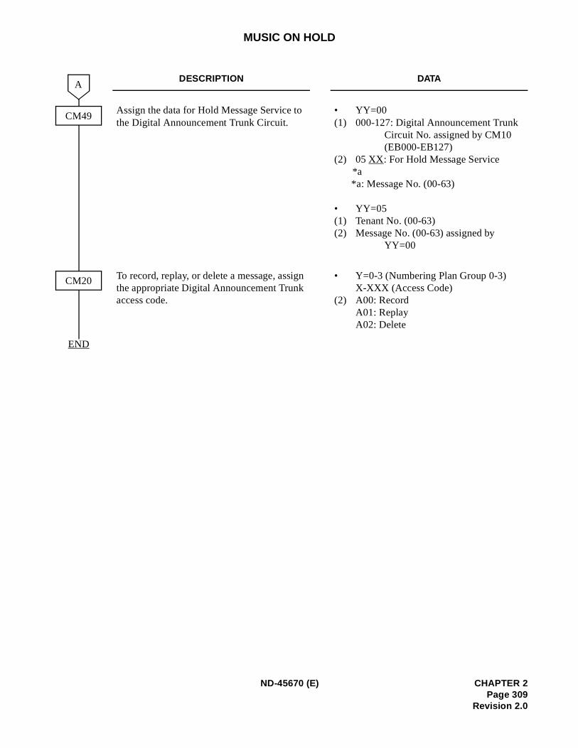
MUSIC ON HOLD
DESCRIPTION DATA
Assign the data for Hold Message Service to the Digital Announcement Trunk Circuit.
• YY=00(1) 000-127: Digital Announcement Trunk
Circuit No. assigned by CM10 (EB000-EB127)
(2) 05 XX: For Hold Message Service*a *a: Message No. (00-63)
• YY=05(1) Tenant No. (00-63)(2) Message No. (00-63) assigned by
YY=00
To record, replay, or delete a message, assign the appropriate Digital Announcement Trunk access code.
• Y=0-3 (Numbering Plan Group 0-3)X-XXX (Access Code)
(2) A00: Record A01: ReplayA02: Delete
CM49
A
END
CM20
ND-45670 (E) CHAPTER 2Page 309
Revision 2.0
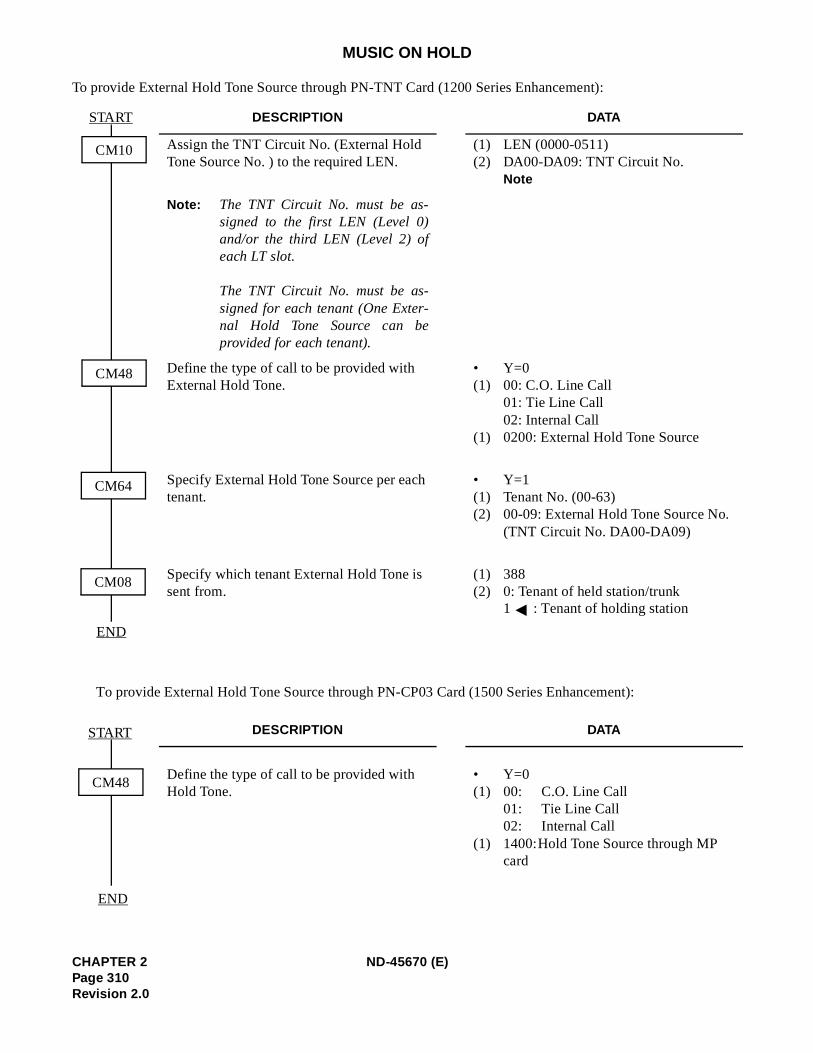
MUSIC ON HOLD
To provide External Hold Tone Source through PN-TNT Card (1200 Series Enhancement):
To provide External Hold Tone Source through PN-CP03 Card (1500 Series Enhancement):
DESCRIPTION DATA
Assign the TNT Circuit No. (External Hold Tone Source No. ) to the required LEN.
(1) LEN (0000-0511)(2) DA00-DA09: TNT Circuit No.
Note
Note: The TNT Circuit No. must be as-signed to the first LEN (Level 0)and/or the third LEN (Level 2) ofeach LT slot.
The TNT Circuit No. must be as-signed for each tenant (One Exter-nal Hold Tone Source can beprovided for each tenant).
Define the type of call to be provided with External Hold Tone.
• Y=0(1) 00: C.O. Line Call
01: Tie Line Call02: Internal Call
(1) 0200: External Hold Tone Source
Specify External Hold Tone Source per each tenant.
• Y=1(1) Tenant No. (00-63)(2) 00-09: External Hold Tone Source No.
(TNT Circuit No. DA00-DA09)
Specify which tenant External Hold Tone is sent from.
(1) 388(2) 0: Tenant of held station/trunk
1 : Tenant of holding station
DESCRIPTION DATA
Define the type of call to be provided with Hold Tone.
• Y=0(1) 00: C.O. Line Call
01: Tie Line Call02: Internal Call
(1) 1400:Hold Tone Source through MP card
START
END
CM10
CM48
CM64
CM08
CM48
END
START
CHAPTER 2 ND-45670 (E)Page 310Revision 2.0
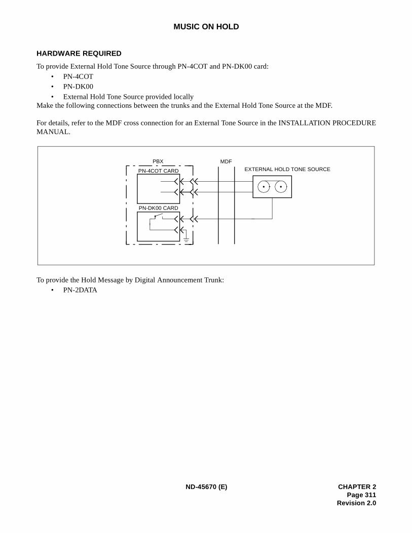
URE
MUSIC ON HOLD
HARDWARE REQUIRED
To provide External Hold Tone Source through PN-4COT and PN-DK00 card:
• PN-4COT• PN-DK00
• External Hold Tone Source provided locallyMake the following connections between the trunks and the External Hold Tone Source at the MDF.
For details, refer to the MDF cross connection for an External Tone Source in the INSTALLATION PROCEDMANUAL.
To provide the Hold Message by Digital Announcement Trunk:• PN-2DATA
PN-DK00 CARD
PN-4COT CARD
PBX
EXTERNAL HOLD TONE SOURCE
MDF
ND-45670 (E) CHAPTER 2Page 311
Revision 2.0
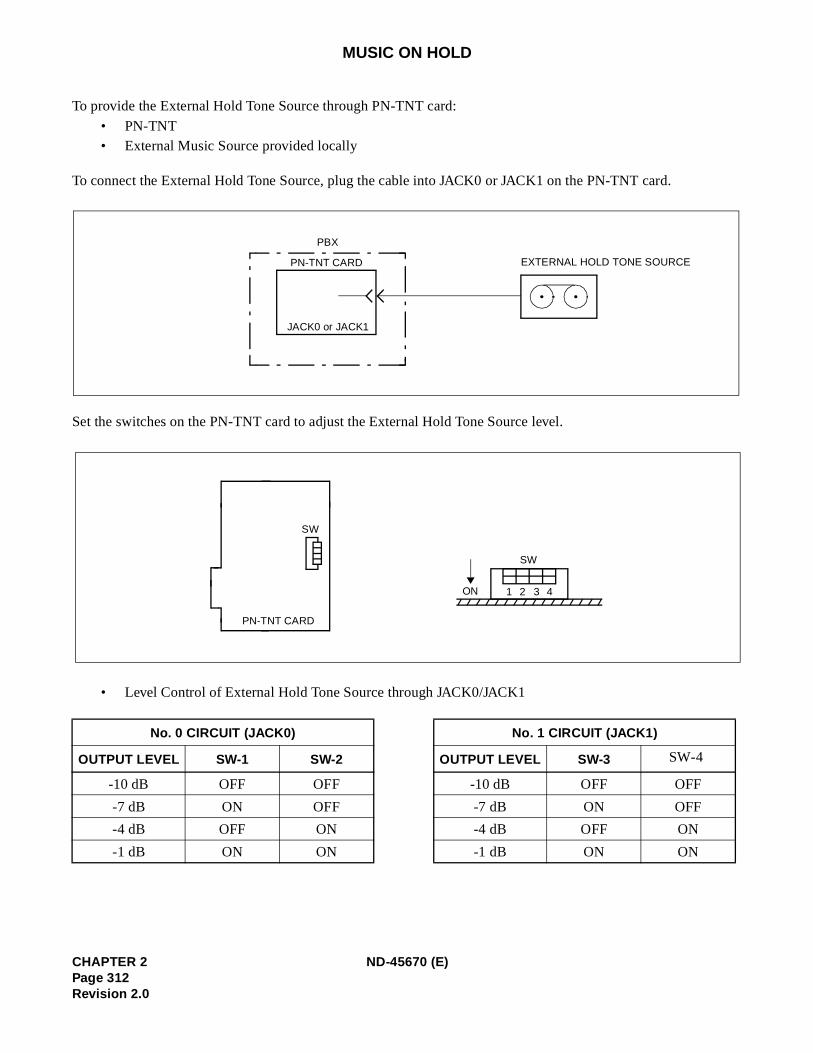
MUSIC ON HOLD
To provide the External Hold Tone Source through PN-TNT card:
• PN-TNT• External Music Source provided locally
To connect the External Hold Tone Source, plug the cable into JACK0 or JACK1 on the PN-TNT card.
Set the switches on the PN-TNT card to adjust the External Hold Tone Source level.
• Level Control of External Hold Tone Source through JACK0/JACK1
No. 0 CIRCUIT (JACK0) No. 1 CIRCUIT (JACK1)
OUTPUT LEVEL SW-1 SW-2 OUTPUT LEVEL SW-3 SW-4
-10 dB OFF OFF -10 dB OFF OFF
-7 dB ON OFF -7 dB ON OFF
-4 dB OFF ON -4 dB OFF ON
-1 dB ON ON -1 dB ON ON
JACK0 or JACK1
PN-TNT CARD
PBX
EXTERNAL HOLD TONE SOURCE
SW
SW
PN-TNT CARD
ON 1 2 3 4
CHAPTER 2 ND-45670 (E)Page 312Revision 2.0
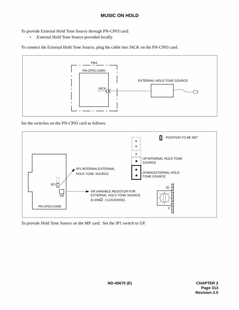
MUSIC ON HOLD
To provide External Hold Tone Source through PN-CP03 card:
• External Hold Tone Source provided locally.
To connect the External Hold Tone Source, plug the cable into JACK on the PN-CP03 card.
Set the switches on the PN-CP03 card as follows.
To provide Hold Tone Source on the MP card: Set the JP1 switch to UP.
JACK
PN-CP03 CARD
PBX
EXTERNAL HOLD TONE SOURCE
JP1
PN-CP03 CARD
VR
JP1:INTERNAL/EXTERNAL
HOLD TONE SOURCE
VR:VARIABLE RESISTOR FOR EXTERNAL HOLD TONE SOURCE
(0-20kΩ : CLOCKWISE)
20
0
DOWN:EXTERNAL HOLD TONE SOURCE
UP:INTERNAL HOLD TONE SOURCE
: POSITION TO BE SET
ND-45670 (E) CHAPTER 2Page 313
Revision 2.0
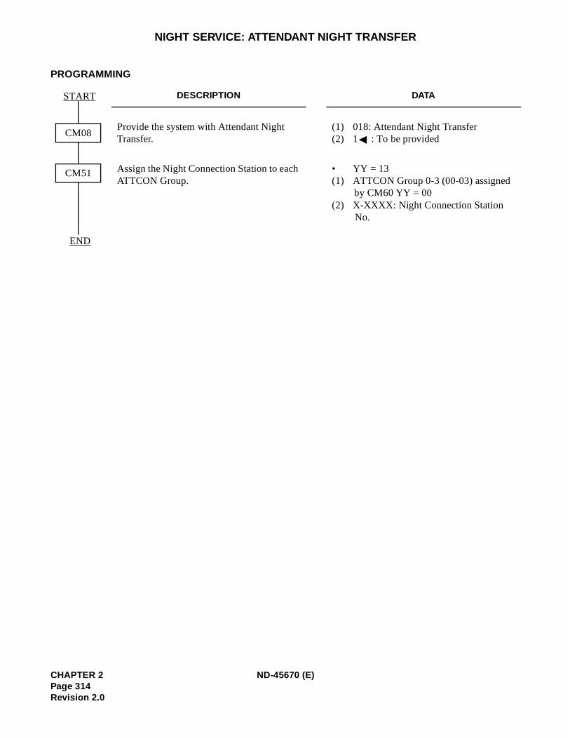
NIGHT SERVICE: ATTENDANT NIGHT TRANSFER
PROGRAMMING
DESCRIPTION DATA
Provide the system with Attendant Night Transfer.
(1) 018: Attendant Night Transfer (2) 1 : To be provided
Assign the Night Connection Station to each ATTCON Group.
• YY = 13(1) ATTCON Group 0-3 (00-03) assigned
by CM60 YY = 00 (2) X-XXXX: Night Connection Station
No.
CM08
START
END
CM51
CHAPTER 2 ND-45670 (E)Page 314Revision 2.0
In-
NIGHT SERVICE: CALL REROUTING
PROGRAMMING
Refer to Night Connection-Fixed/Flexible, Trunk Answer Any Station, Direct Inward Termination (DIT), Directward Dialing (DID), and E&M Tie Line Access.
ND-45670 (E) CHAPTER 2Page 315
Revision 2.0
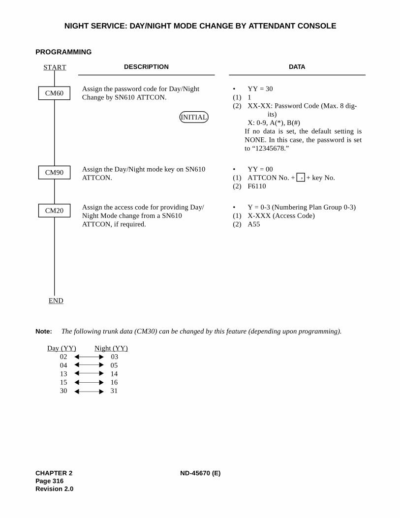
t
NIGHT SERVICE: DAY/NIGHT MODE CHANGE BY ATTENDANT CONSOLE
PROGRAMMING
Note: The following trunk data (CM30) can be changed by this feature (depending upon programming).
Day (YY) Night (YY)02 0304 0513 1415 1630 31
DESCRIPTION DATA
Assign the password code for Day/Night Change by SN610 ATTCON.
• YY = 30(1) 1 (2) XX-XX: Password Code (Max. 8 dig-
its)X: 0-9, A(*), B(#)
If no data is set, the default setting isNONE. In this case, the password is seto “12345678.”
Assign the Day/Night mode key on SN610 ATTCON.
• YY = 00(1) ATTCON No. + + key No.(2) F6110
Assign the access code for providing Day/Night Mode change from a SN610 ATTCON, if required.
• Y = 0-3 (Numbering Plan Group 0-3) (1) X-XXX (Access Code) (2) A55
CM60
START
CM20
END
CM90
INITIAL
,
CHAPTER 2 ND-45670 (E)Page 316Revision 2.0
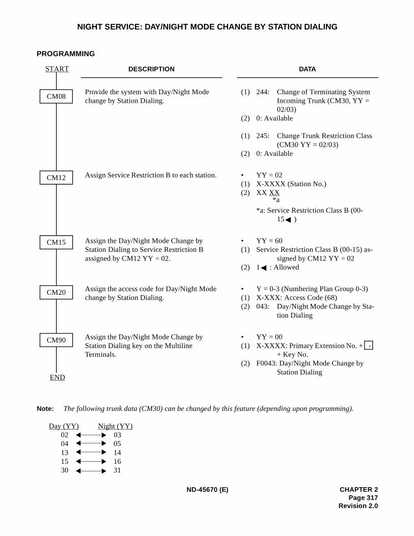
NIGHT SERVICE: DAY/NIGHT MODE CHANGE BY STATION DIALING
PROGRAMMING
Note: The following trunk data (CM30) can be changed by this feature (depending upon programming).
Day (YY) Night (YY)02 0304 0513 1415 1630 31
DESCRIPTION DATA
Provide the system with Day/Night Mode change by Station Dialing.
(1) 244: Change of Terminating System Incoming Trunk (CM30, YY = 02/03)
(2) 0: Available
(1) 245: Change Trunk Restriction Class (CM30 YY = 02/03)
(2) 0: Available
Assign Service Restriction B to each station. • YY = 02(1) X-XXXX (Station No.) (2) XX XX
*a: Service Restriction Class B (00-15 )
Assign the Day/Night Mode Change by Station Dialing to Service Restriction B assigned by CM12 YY = 02.
• YY = 60(1) Service Restriction Class B (00-15) as-
signed by CM12 YY = 02(2) 1 : Allowed
Assign the access code for Day/Night Mode change by Station Dialing.
• Y = 0-3 (Numbering Plan Group 0-3) (1) X-XXX: Access Code (68) (2) 043: Day/Night Mode Change by Sta-
tion Dialing
Assign the Day/Night Mode Change by Station Dialing key on the Multiline Terminals.
• YY = 00(1) X-XXXX: Primary Extension No. +
+ Key No. (2) F0043: Day/Night Mode Change by
Station Dialing
CM08
START
CM12
CM15
CM90
CM20
END
*a
,
ND-45670 (E) CHAPTER 2Page 317
Revision 2.0
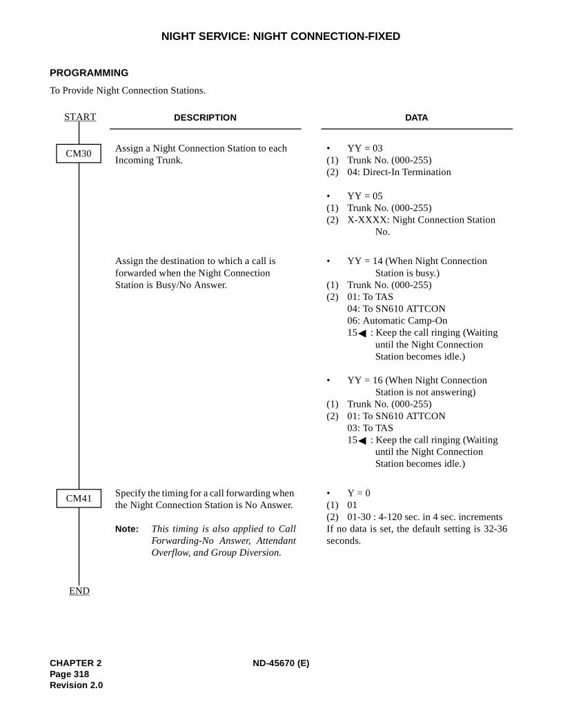
NIGHT SERVICE: NIGHT CONNECTION-FIXED
PROGRAMMING
To Provide Night Connection Stations.
DESCRIPTION DATA
Assign a Night Connection Station to each Incoming Trunk.
• YY = 03(1) Trunk No. (000-255) (2) 04: Direct-In Termination
• YY = 05(1) Trunk No. (000-255) (2) X-XXXX: Night Connection Station
No.
Assign the destination to which a call is forwarded when the Night Connection Station is Busy/No Answer.
• YY = 14 (When Night Connection Station is busy.)
(1) Trunk No. (000-255) (2) 01: To TAS
04: To SN610 ATTCON 06: Automatic Camp-On 15 : Keep the call ringing (Waiting
until the Night Connection Station becomes idle.)
• YY = 16 (When Night Connection Station is not answering)
(1) Trunk No. (000-255) (2) 01: To SN610 ATTCON
03: To TAS15 : Keep the call ringing (Waiting
until the Night Connection Station becomes idle.)
Specify the timing for a call forwarding when the Night Connection Station is No Answer.
Note: This timing is also applied to CallForwarding-No Answer, AttendantOverflow, and Group Diversion.
• Y = 0 (1) 01 (2) 01-30 : 4-120 sec. in 4 sec. incrementsIf no data is set, the default setting is 32-36seconds.
CM30
START
END
CM41
CHAPTER 2 ND-45670 (E)Page 318Revision 2.0

NIGHT SERVICE: NIGHT CONNECTION-FLEXIBLE
PROGRAMMING
Refer to Night Connection-Fixed and Call Forwarding-All Calls.
ND-45670 (E) CHAPTER 2Page 319
Revision 2.0
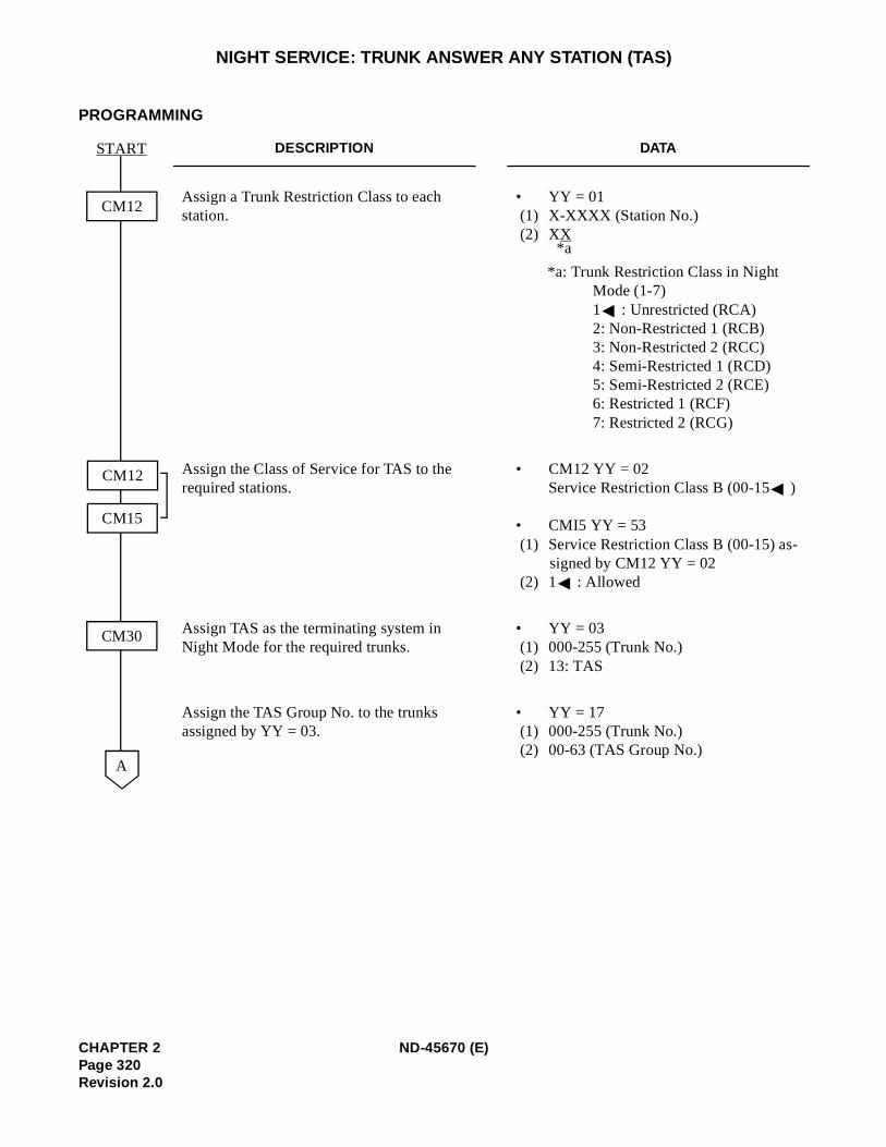
NIGHT SERVICE: TRUNK ANSWER ANY STATION (TAS)
PROGRAMMING
DESCRIPTION DATA
Assign a Trunk Restriction Class to each station.
• YY = 01 (1) X-XXXX (Station No.) (2) XX
*a: Trunk Restriction Class in Night Mode (1-7) 1 : Unrestricted (RCA) 2: Non-Restricted 1 (RCB) 3: Non-Restricted 2 (RCC) 4: Semi-Restricted 1 (RCD) 5: Semi-Restricted 2 (RCE) 6: Restricted 1 (RCF) 7: Restricted 2 (RCG)
Assign the Class of Service for TAS to the required stations.
• CM12 YY = 02 Service Restriction Class B (00-15 )
• CMI5 YY = 53 (1) Service Restriction Class B (00-15) as-
signed by CM12 YY = 02 (2) 1 : Allowed
Assign TAS as the terminating system in Night Mode for the required trunks.
• YY = 03 (1) 000-255 (Trunk No.) (2) 13: TAS
Assign the TAS Group No. to the trunks assigned by YY = 03.
• YY = 17 (1) 000-255 (Trunk No.) (2) 00-63 (TAS Group No.)
CM12
START
A
CM30
CM12
CM15
*a
CHAPTER 2 ND-45670 (E)Page 320Revision 2.0
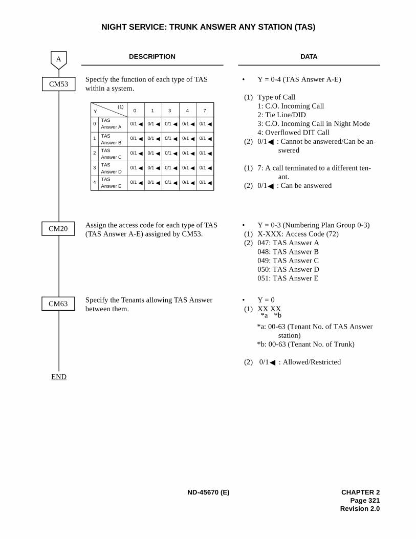
-
NIGHT SERVICE: TRUNK ANSWER ANY STATION (TAS)
DESCRIPTION DATA
Specify the function of each type of TAS within a system.
• Y = 0-4 (TAS Answer A-E)
(1) Type of Call1: C.O. Incoming Call 2: Tie Line/DID 3: C.O. Incoming Call in Night Mode 4: Overflowed DIT Call
(2) 0/1 : Cannot be answered/Can be answered
(1) 7: A call terminated to a different ten-ant.
(2) 0/1 : Can be answered
Assign the access code for each type of TAS (TAS Answer A-E) assigned by CM53.
• Y = 0-3 (Numbering Plan Group 0-3) (1) X-XXX: Access Code (72) (2) 047: TAS Answer A
048: TAS Answer B 049: TAS Answer C 050: TAS Answer D 051: TAS Answer E
Specify the Tenants allowing TAS Answer between them.
• Y = 0 (1) XX XX
*a: 00-63 (Tenant No. of TAS Answer station)
*b: 00-63 (Tenant No. of Trunk)
(2) 0/1 : Allowed/Restricted
END
CM53
A
CM20
CM63
0
1
2
3
4
0 1 3 4 7(1)
Y
0/1
0/1
0/1
0/1
0/1
0/1
0/1
0/1
0/1
0/1
0/1
0/1
0/1
0/1
0/1
0/1
0/1
0/1
0/1
0/1
0/1
0/1
0/1
0/1
0/1
TASAnswer A
TASAnswer B
TASAnswer C
TAS
Answer D
TAS
Answer E
*b*a
ND-45670 (E) CHAPTER 2Page 321
Revision 2.0
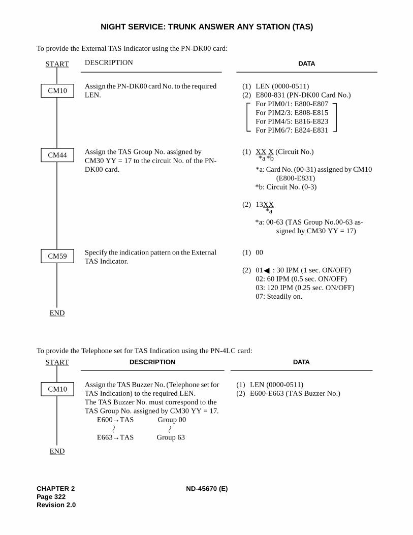
NIGHT SERVICE: TRUNK ANSWER ANY STATION (TAS)
To provide the External TAS Indicator using the PN-DK00 card:
To provide the Telephone set for TAS Indication using the PN-4LC card:
DESCRIPTION DATA
Assign the PN-DK00 card No. to the required LEN.
(1) LEN (0000-0511) (2) E800-831 (PN-DK00 Card No.)
For PIM0/1: E800-E807 For PIM2/3: E808-E815 For PIM4/5: E816-E823 For PIM6/7: E824-E831
Assign the TAS Group No. assigned by CM30 YY = 17 to the circuit No. of the PN-DK00 card.
(1) XX X (Circuit No.)
*a: Card No. (00-31) assigned by CM10 (E800-E831)
*b: Circuit No. (0-3)
(2) 13XX
*a: 00-63 (TAS Group No.00-63 as-signed by CM30 YY = 17)
Specify the indication pattern on the External TAS Indicator.
(1) 00
(2) 01 : 30 IPM (1 sec. ON/OFF) 02: 60 IPM (0.5 sec. ON/OFF) 03: 120 IPM (0.25 sec. ON/OFF) 07: Steadily on.
DESCRIPTION DATA
Assign the TAS Buzzer No. (Telephone set for TAS Indication) to the required LEN.The TAS Buzzer No. must correspond to the TAS Group No. assigned by CM30 YY = 17.
E600→TAS Group 00
E663→TAS Group 63
(1) LEN (0000-0511) (2) E600-E663 (TAS Buzzer No.)
CM10
START
CM59
END
CM44 *b*a
*a
CM10
START
END
CHAPTER 2 ND-45670 (E)Page 322Revision 2.0
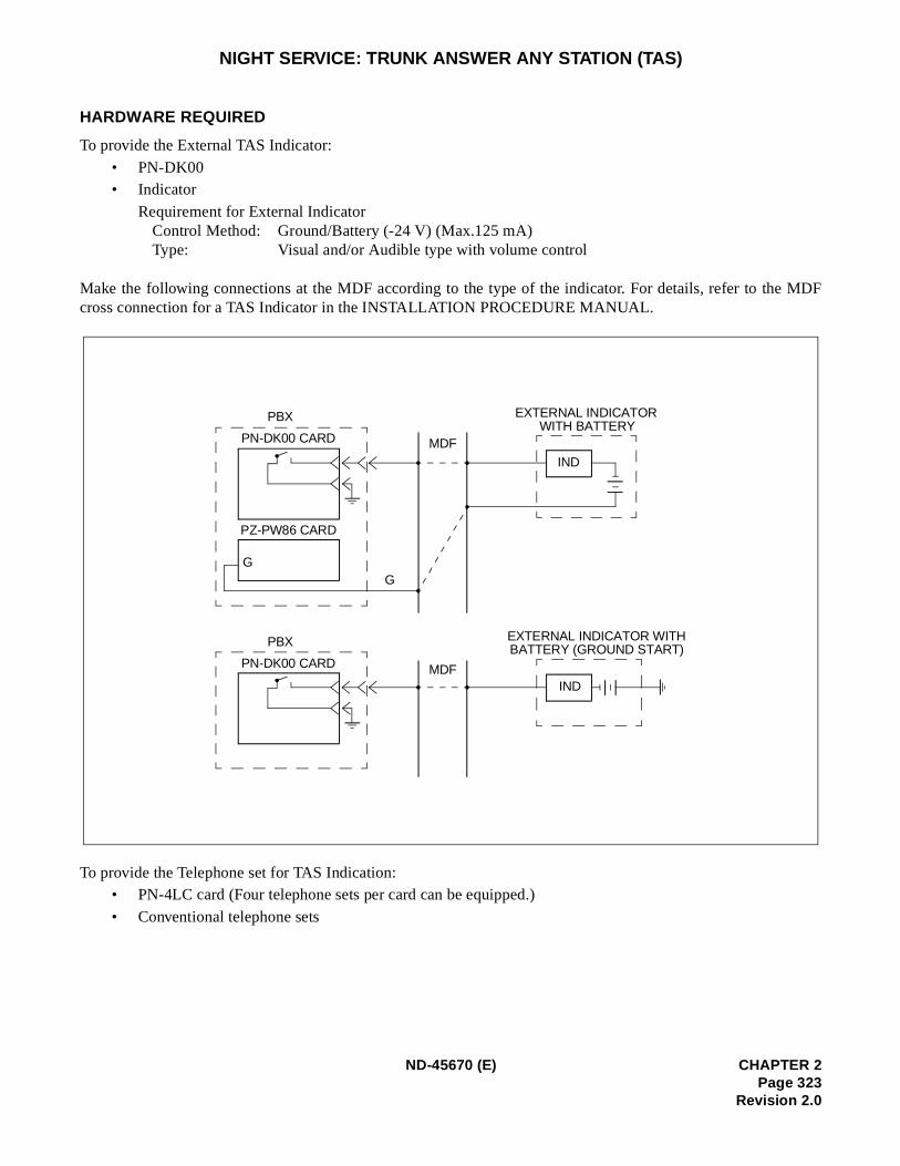
MDF
NIGHT SERVICE: TRUNK ANSWER ANY STATION (TAS)
HARDWARE REQUIRED
To provide the External TAS Indicator:
• PN-DK00• Indicator
Requirement for External IndicatorControl Method: Ground/Battery (-24 V) (Max.125 mA) Type: Visual and/or Audible type with volume control
Make the following connections at the MDF according to the type of the indicator. For details, refer to thecross connection for a TAS Indicator in the INSTALLATION PROCEDURE MANUAL.
To provide the Telephone set for TAS Indication: • PN-4LC card (Four telephone sets per card can be equipped.)
• Conventional telephone sets
PBX
PN-DK00 CARD
PZ-PW86 CARD
G
PBX
PN-DK00 CARD
MDF
MDF
EXTERNAL INDICATORWITH BATTERY
EXTERNAL INDICATOR WITHBATTERY (GROUND START)
IND
IND
G
ND-45670 (E) CHAPTER 2Page 323
Revision 2.0
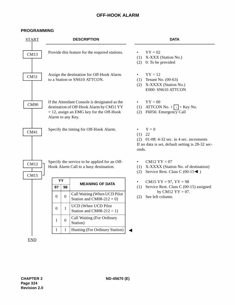
-
OFF-HOOK ALARM
PROGRAMMING
DESCRIPTION DATA
Provide this feature for the required stations. • YY = 02(1) X-XXX (Station No.) (2) 0: To be provided
Assign the destination for Off-Hook Alarm to a Station or SN610 ATTCON.
• YY = 12 (1) Tenant No. (00-63) (2) X-XXXX (Station No.)
E000: SN610 ATTCON
If the Attendant Console is designated as the destination of Off-Hook Alarm by CM51 YY = 12, assign an EMG key for the Off-Hook Alarm to any Key.
• YY = 00(1) ATTCON No. + + Key No.(2) F6056: Emergency Call
Specify the timing for Off-Hook Alarm. • Y = 0 (1) 22(2) 01-08: 4-32 sec. in 4 sec. incrementsIf no data is set, default setting is 28-32 seconds.
Specify the service to be applied for an Off-Hook Alarm Call to a busy destination.
• CM12 YY = 07 (1) X-XXXX (Station No. of destination) (2) Service Rest. Class C (00-15 )
• CM15 YY = 97, YY = 98 (1) Service Rest. Class C (00-15) assigned
by CM12 YY = 07.(2) See left column.
CM13
START
CM41
CM12
CM15
END
CM90
CM51
,
YYMEANING OF DATA
97 98
0 0Call Waiting (When UCD Pilot Station and CM08-212 = 0)
0 1UCD (When UCD Pilot Station and CM08-212 = 1)
1 0Call Waiting (For Ordinary Station)
1 1 Hunting (For Ordinary Station)
CHAPTER 2 ND-45670 (E)Page 324Revision 2.0
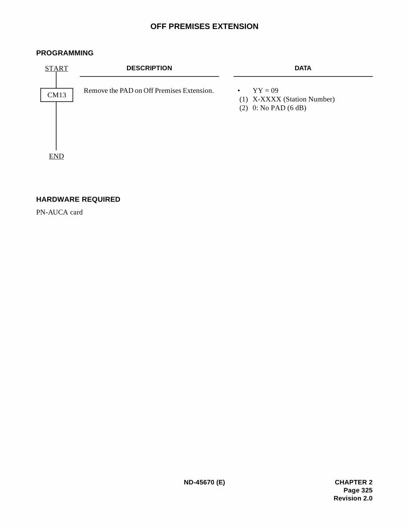
OFF PREMISES EXTENSION
PROGRAMMING
HARDWARE REQUIRED
PN-AUCA card
DESCRIPTION DATA
Remove the PAD on Off Premises Extension. • YY = 09 (1) X-XXXX (Station Number) (2) 0: No PAD (6 dB)
CM13
START
END
ND-45670 (E) CHAPTER 2Page 325
Revision 2.0
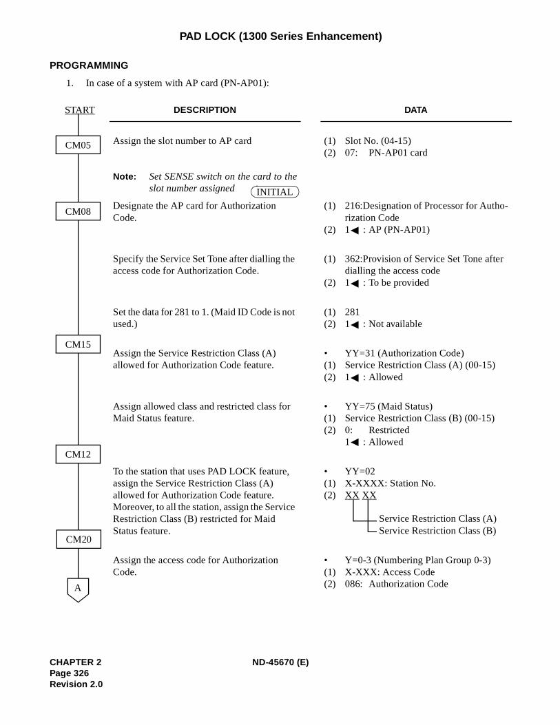
-
PAD LOCK (1300 Series Enhancement)
PROGRAMMING
1. In case of a system with AP card (PN-AP01):
DESCRIPTION DATA
Assign the slot number to AP card
Note: Set SENSE switch on the card to theslot number assigned
(1) Slot No. (04-15)(2) 07: PN-AP01 card
Designate the AP card for Authorization Code.
(1) 216:Designation of Processor for Authorization Code
(2) 1 : AP (PN-AP01)
Specify the Service Set Tone after dialling the access code for Authorization Code.
(1) 362:Provision of Service Set Tone after dialling the access code
(2) 1 : To be provided
Set the data for 281 to 1. (Maid ID Code is not used.)
(1) 281(2) 1 : Not available
Assign the Service Restriction Class (A) allowed for Authorization Code feature.
• YY=31 (Authorization Code)(1) Service Restriction Class (A) (00-15)(2) 1 : Allowed
Assign allowed class and restricted class for Maid Status feature.
• YY=75 (Maid Status)(1) Service Restriction Class (B) (00-15)(2) 0: Restricted
1 : Allowed
To the station that uses PAD LOCK feature, assign the Service Restriction Class (A) allowed for Authorization Code feature. Moreover, to all the station, assign the Service Restriction Class (B) restricted for Maid Status feature.
• YY=02(1) X-XXXX: Station No.(2) XX XX
Service Restriction Class (A)Service Restriction Class (B)
Assign the access code for Authorization Code.
• Y=0-3 (Numbering Plan Group 0-3)(1) X-XXX: Access Code(2) 086: Authorization Code
CM05
CM08
CM15
CM12
CM20
A
START
INITIAL
CHAPTER 2 ND-45670 (E)Page 326Revision 2.0
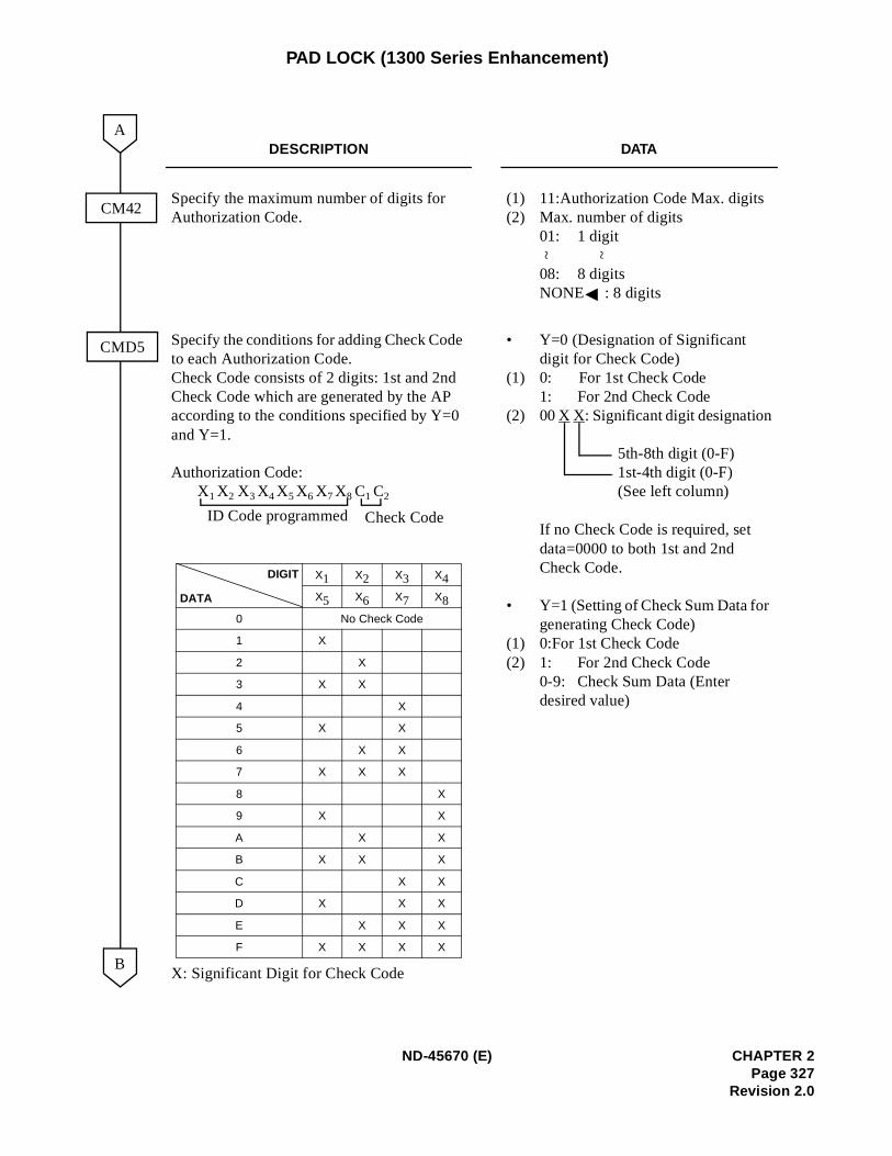
PAD LOCK (1300 Series Enhancement)
DESCRIPTION DATA
Specify the maximum number of digits for Authorization Code.
(1) 11:Authorization Code Max. digits(2) Max. number of digits
01: 1 digit
08: 8 digitsNONE : 8 digits
Specify the conditions for adding Check Code to each Authorization Code.Check Code consists of 2 digits: 1st and 2nd Check Code which are generated by the AP according to the conditions specified by Y=0 and Y=1.
Authorization Code:X1 X2 X3 X4 X5 X6 X7 X8 C1 C2
X: Significant Digit for Check Code
• Y=0 (Designation of Significant digit for Check Code)
(1) 0: For 1st Check Code1: For 2nd Check Code
(2) 00 X X: Significant digit designation
5th-8th digit (0-F)1st-4th digit (0-F)(See left column)
If no Check Code is required, set data=0000 to both 1st and 2nd Check Code.
• Y=1 (Setting of Check Sum Data for generating Check Code)
(1) 0:For 1st Check Code(2) 1: For 2nd Check Code
0-9: Check Sum Data (Enter desired value)
CM42
CMD5
A
B
~ ~
ID Code programmed Check Code
X1 X2 X3 X4
X5 X6 X7 X8
0 No Check Code
1 X
2 X
3 X X
4 X
5 X X
6 X X
7 X X X
8 X
9 X X
A X X
B X X X
C X X
D X X X
E X X X
F X X X X
DIGIT
DATA
ND-45670 (E) CHAPTER 2Page 327
Revision 2.0
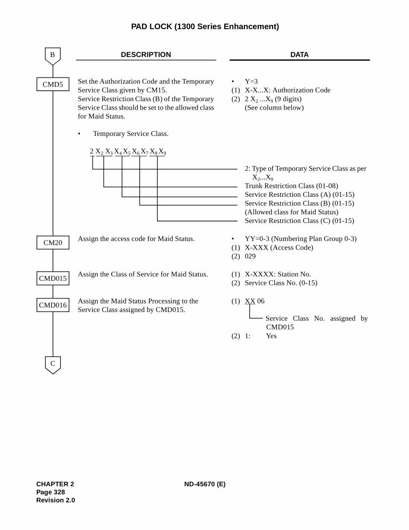
PAD LOCK (1300 Series Enhancement)
DESCRIPTION DATA
Set the Authorization Code and the TemporaryService Class given by CM15. Service Restriction Class (B) of the TemporaryService Class should be set to the allowed classfor Maid Status.
• Temporary Service Class.
2 X2 X3 X4 X5 X6 X7 X8 X9
•(1)(2)
Y=3X-X...X: Authorization Code2 X2 ...X9 (9 digits)(See column below)
2: Type of Temporary Service Class as perX2...X9
Trunk Restriction Class (01-08)Service Restriction Class (A) (01-15)Service Restriction Class (B) (01-15)(Allowed class for Maid Status)Service Restriction Class (C) (01-15)
Assign the access code for Maid Status. •(1)(2)
YY=0-3 (Numbering Plan Group 0-3)X-XXX (Access Code)029
Assign the Class of Service for Maid Status. (1)(2)
X-XXXX: Station No.Service Class No. (0-15)
Assign the Maid Status Processing to the Service Class assigned by CMD015.
(1)
(2)
XX 06
Service Class No. assigned byCMD015
1: Yes
CMD5
CM20
C
CMD015
CMD016
B
CHAPTER 2 ND-45670 (E)Page 328Revision 2.0
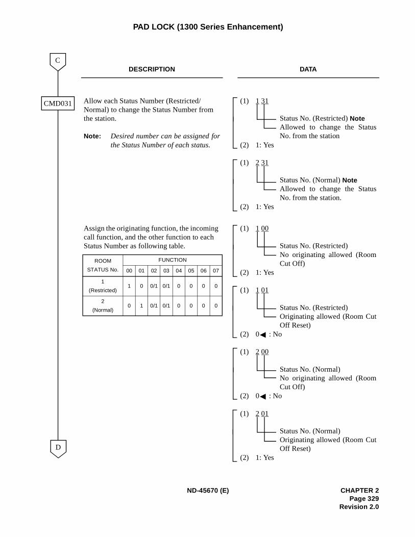
PAD LOCK (1300 Series Enhancement)
DESCRIPTION DATA
Allow each Status Number (Restricted/Normal) to change the Status Number from the station.
Note: Desired number can be assigned forthe Status Number of each status.
(1) 1 31
Status No. (Restricted) NoteAllowed to change the StatusNo. from the station
(2) 1: Yes
(1) 2 31
Status No. (Normal) NoteAllowed to change the StatusNo. from the station.
(2) 1: Yes
Assign the originating function, the incoming call function, and the other function to each Status Number as following table.
(1) 1 00
Status No. (Restricted)No originating allowed (RoomCut Off)
(2) 1: Yes
(1) 1 01
Status No. (Restricted)Originating allowed (Room CutOff Reset)
(2) 0 : No
(1) 2 00
Status No. (Normal)No originating allowed (RoomCut Off)
(2) 0 : No
(1) 2 01
Status No. (Normal)Originating allowed (Room CutOff Reset)
(2) 1: Yes
CMD031
D
C
ROOM
STATUS No.
FUNCTION
00 01 02 03 04 05 06 07
1
(Restricted)1 0 0/1 0/1 0 0 0 0
2
(Normal)0 1 0/1 0/1 0 0 0 0
ND-45670 (E) CHAPTER 2Page 329
Revision 2.0
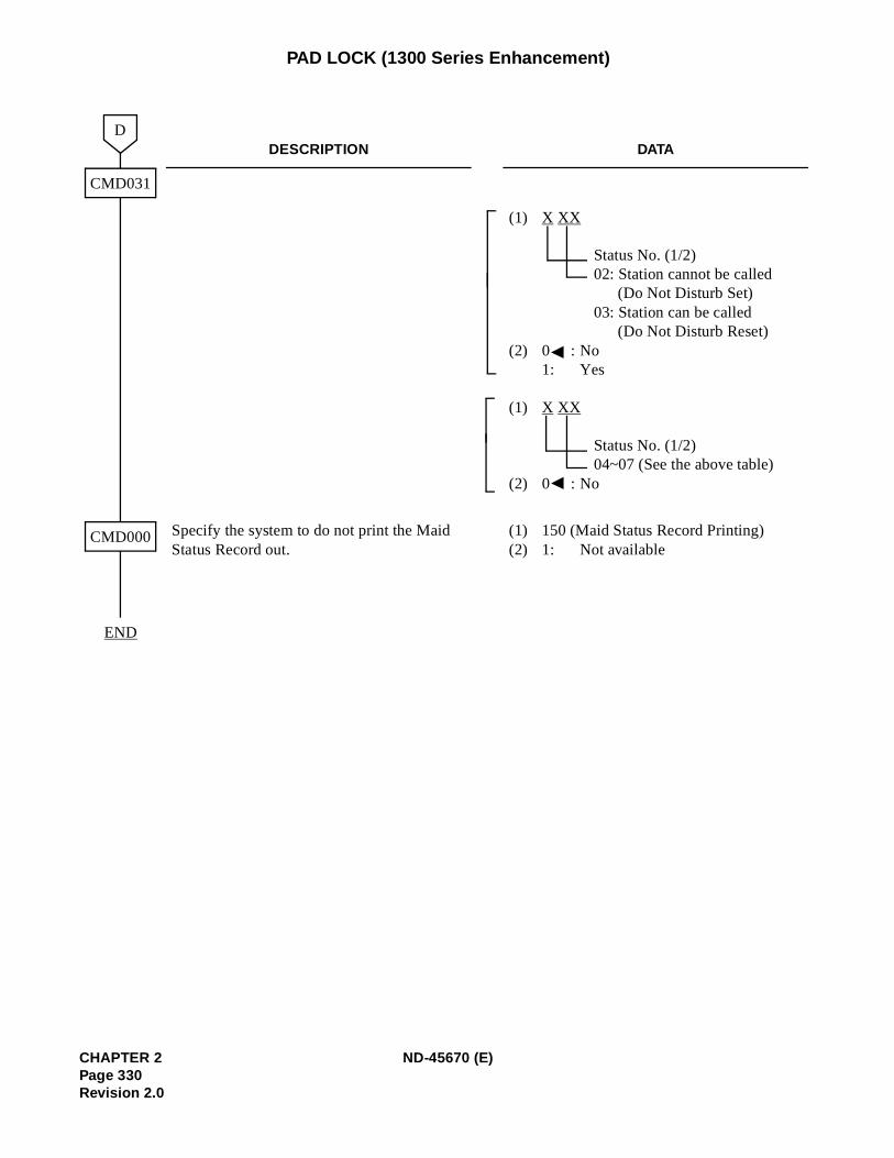
PAD LOCK (1300 Series Enhancement)
DESCRIPTION DATA
(1) X XX
Status No. (1/2) 02: Station cannot be called
(Do Not Disturb Set)03: Station can be called
(Do Not Disturb Reset)(2) 0 : No
1: Yes
(1) X XX
Status No. (1/2)04~07 (See the above table)
(2) 0 : No
Specify the system to do not print the Maid Status Record out.
(1) 150 (Maid Status Record Printing)(2) 1: Not available
CMD031
D
CMD000
END
CHAPTER 2 ND-45670 (E)Page 330Revision 2.0
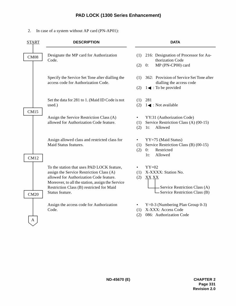
PAD LOCK (1300 Series Enhancement)
2. In case of a system without AP card (PN-AP01):
DESCRIPTION DATA
Designate the MP card for Authorization Code.
(1) 216: Designation of Processor for Au-thorization Code
(2) 0: MP (PN-CP00) card
Specify the Service Set Tone after dialling the access code for Authorization Code.
(1) 362: Provision of Service Set Tone afterdialling the access code
(2) 1 : To be provided
Set the data for 281 to 1. (Maid ID Code is not used.)
(1) 281(2) 1 : Not available
Assign the Service Restriction Class (A) allowed for Authorization Code feature.
• YY:31 (Authorization Code)(1) Service Restriction Class (A) (00-15)(2) 1t: Allowed
Assign allowed class and restricted class for Maid Status features.
• YY=75 (Maid Status)(1) Service Restriction Class (B) (00-15)(2) 0: Restricted
1t: Allowed
To the station that uses PAD LOCK feature, assign the Service Restriction Class (A) allowed for Authorization Code feature. Moreover, to all the station, assign the Service Restriction Class (B) restricted for Maid Status feature.
• YY=02(1) X-XXXX: Station No.(2) XX XX
Service Restriction Class (A)Service Restriction Class (B)
Assign the access code for Authorization Code.
• Y=0-3 (Numbering Plan Group 0-3)(1) X-XXX: Access Code(2) 086: Authorization Code
CM08
CM20
A
CM15
CM12
START
ND-45670 (E) CHAPTER 2Page 331
Revision 2.0
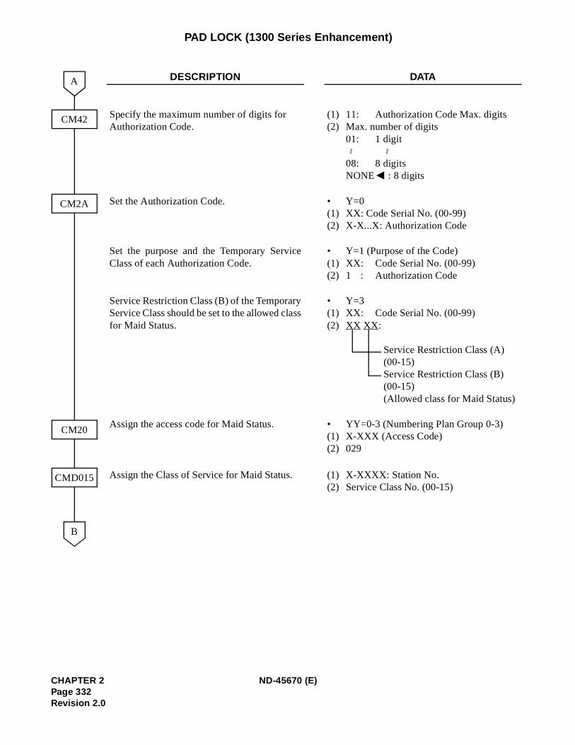
PAD LOCK (1300 Series Enhancement)
DESCRIPTION DATA
Specify the maximum number of digits for Authorization Code.
(1)(2)
11: Authorization Code Max. digitsMax. number of digits01: 1 digit
08: 8 digitsNONE : 8 digits
Set the Authorization Code. •(1)(2)
Y=0XX: Code Serial No. (00-99)X-X...X: Authorization Code
Set the purpose and the Temporary ServiceClass of each Authorization Code.
•(1)(2)
Y=1 (Purpose of the Code)XX: Code Serial No. (00-99)1 : Authorization Code
Service Restriction Class (B) of the TemporaryService Class should be set to the allowed classfor Maid Status.
•(1)(2)
Y=3XX: Code Serial No. (00-99)XX XX:
Service Restriction Class (A) (00-15)Service Restriction Class (B) (00-15) (Allowed class for Maid Status)
Assign the access code for Maid Status. •(1)(2)
YY=0-3 (Numbering Plan Group 0-3)X-XXX (Access Code)029
Assign the Class of Service for Maid Status. (1)(2)
X-XXXX: Station No.Service Class No. (00-15)
CM42
CM20
B
A
CM2A
CMD015
~ ~
CHAPTER 2 ND-45670 (E)Page 332Revision 2.0
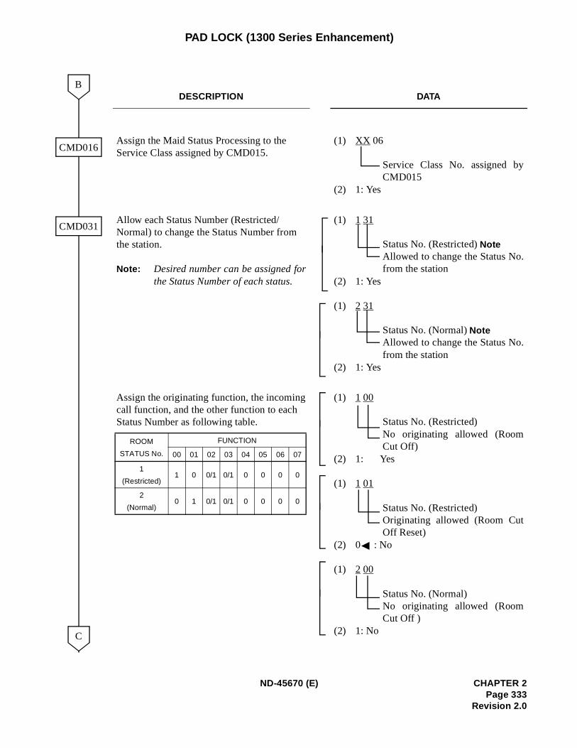
PAD LOCK (1300 Series Enhancement)
DESCRIPTION DATA
Assign the Maid Status Processing to the Service Class assigned by CMD015.
(1) XX 06
Service Class No. assigned byCMD015
(2) 1: Yes
Allow each Status Number (Restricted/Normal) to change the Status Number from the station.
Note: Desired number can be assigned forthe Status Number of each status.
(1) 1 31
Status No. (Restricted) NoteAllowed to change the Status No.from the station
(2) 1: Yes
(1) 2 31
Status No. (Normal) NoteAllowed to change the Status No.from the station
(2) 1: Yes
Assign the originating function, the incomingcall function, and the other function to each Status Number as following table.
(1) 1 00
Status No. (Restricted)No originating allowed (RoomCut Off)
(2) 1: Yes
(1) 1 01
Status No. (Restricted)Originating allowed (Room CutOff Reset)
(2) 0 : No
(1) 2 00
Status No. (Normal)No originating allowed (RoomCut Off )
(2) 1: No
CMD016
CMD031
C
B
ROOM
STATUS No.
FUNCTION
00 01 02 03 04 05 06 07
1
(Restricted)1 0 0/1 0/1 0 0 0 0
2
(Normal)0 1 0/1 0/1 0 0 0 0
ND-45670 (E) CHAPTER 2Page 333
Revision 2.0
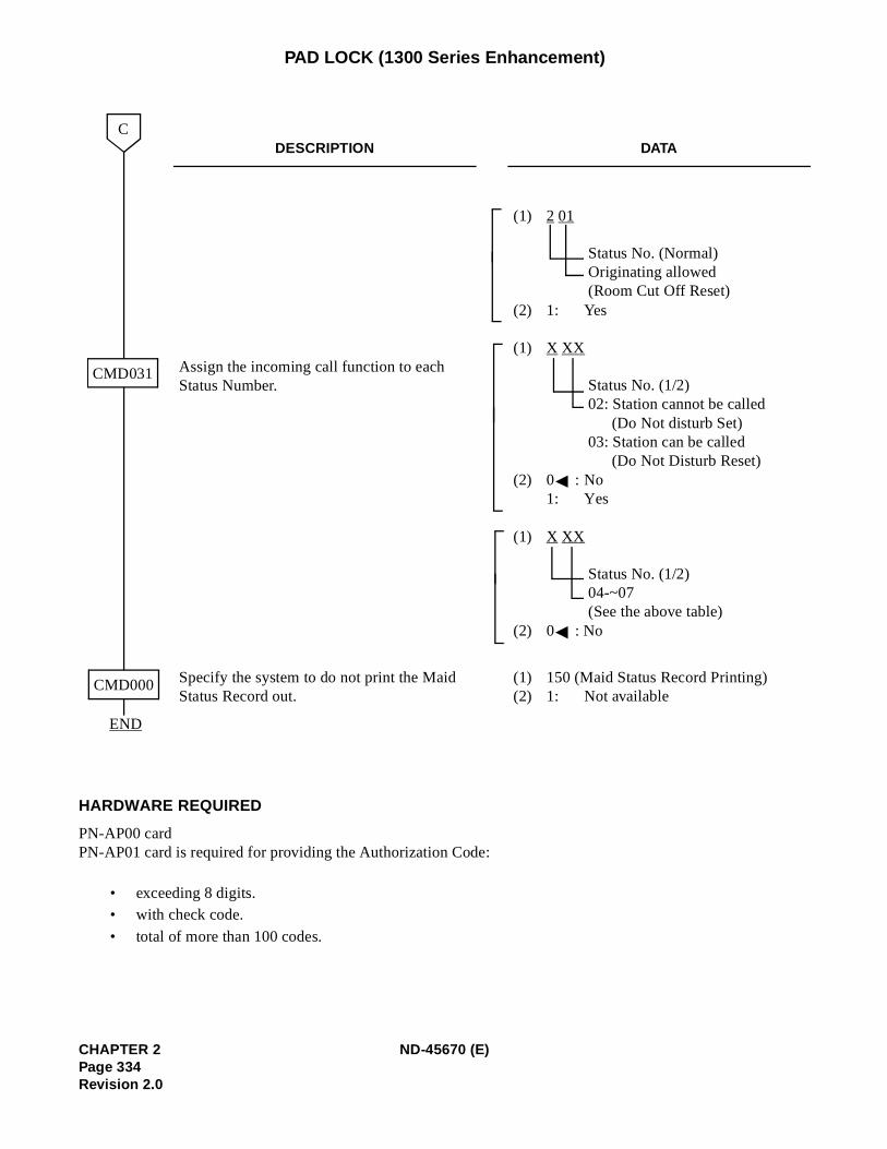
PAD LOCK (1300 Series Enhancement)
HARDWARE REQUIRED
PN-AP00 cardPN-AP01 card is required for providing the Authorization Code:
• exceeding 8 digits.• with check code.
• total of more than 100 codes.
DESCRIPTION DATA
Assign the incoming call function to each Status Number.
(1) 2 01
Status No. (Normal)Originating allowed (Room Cut Off Reset)
(2) 1: Yes
(1) X XX
Status No. (1/2)02: Station cannot be called
(Do Not disturb Set)03: Station can be called
(Do Not Disturb Reset)(2) 0 : No
1: Yes
(1) X XX
Status No. (1/2)04-~07(See the above table)
(2) 0 : No
Specify the system to do not print the Maid Status Record out.
(1) 150 (Maid Status Record Printing)(2) 1: Not available
CMD031
C
CMD000
END
CHAPTER 2 ND-45670 (E)Page 334Revision 2.0
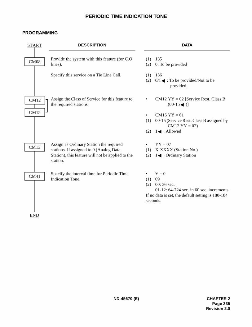
y
s
PERIODIC TIME INDICATION TONE
PROGRAMMING
DESCRIPTION DATA
Provide the system with this feature (for C.O lines).
Specify this service on a Tie Line Call.
(1) 135(2) 0: To be provided
(1) 136(2) 0/1 : To be provided/Not to be
provided.
Assign the Class of Service for this feature to the required stations.
• CM12 YY = 02 [Service Rest. Class B (00-15 )]
• CM15 YY = 61(1) 00-15 (Service Rest. Class B assigned b
CM12 YY = 02) (2) 1 : Allowed
Assign as Ordinary Station the required stations. If assigned to 0 (Analog Data Station), this feature will not be applied to the station.
• YY = 07(1) X-XXXX (Station No.)(2) 1 : Ordinary Station
Specify the interval time for Periodic Time Indication Tone.
• Y = 0(1) 09(2) 00: 36 sec.
01-12: 64-724 sec. in 60 sec. incrementIf no data is set, the default setting is 180-184seconds.
CM08
START
CM41
CM12
CM15
END
CM13
ND-45670 (E) CHAPTER 2Page 335
Revision 2.0
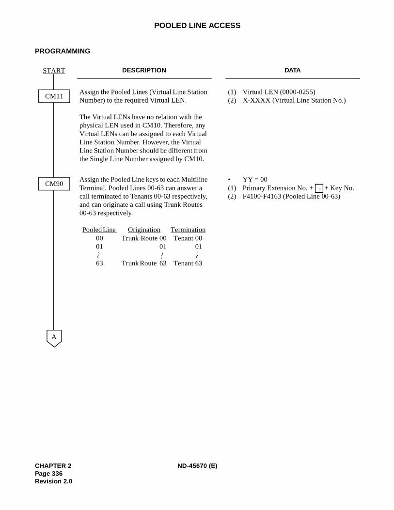
POOLED LINE ACCESS
PROGRAMMING
DESCRIPTION DATA
Assign the Pooled Lines (Virtual Line Station Number) to the required Virtual LEN.
The Virtual LENs have no relation with the physical LEN used in CM10. Therefore, any Virtual LENs can be assigned to each Virtual Line Station Number. However, the Virtual Line Station Number should be different from the Single Line Number assigned by CM10.
(1) Virtual LEN (0000-0255) (2) X-XXXX (Virtual Line Station No.)
Assign the Pooled Line keys to each Multiline Terminal. Pooled Lines 00-63 can answer a call terminated to Tenants 00-63 respectively, and can originate a call using Trunk Routes 00-63 respectively.
Pooled Line Origination Termination00 Trunk Route 00 Tenant 00 01 01 01
63 Trunk Route 63 Tenant 63
• YY = 00(1) Primary Extension No. + + Key No. (2) F4100-F4163 (Pooled Line 00-63)
CM11
START
CM90
A
,
CHAPTER 2 ND-45670 (E)Page 336Revision 2.0
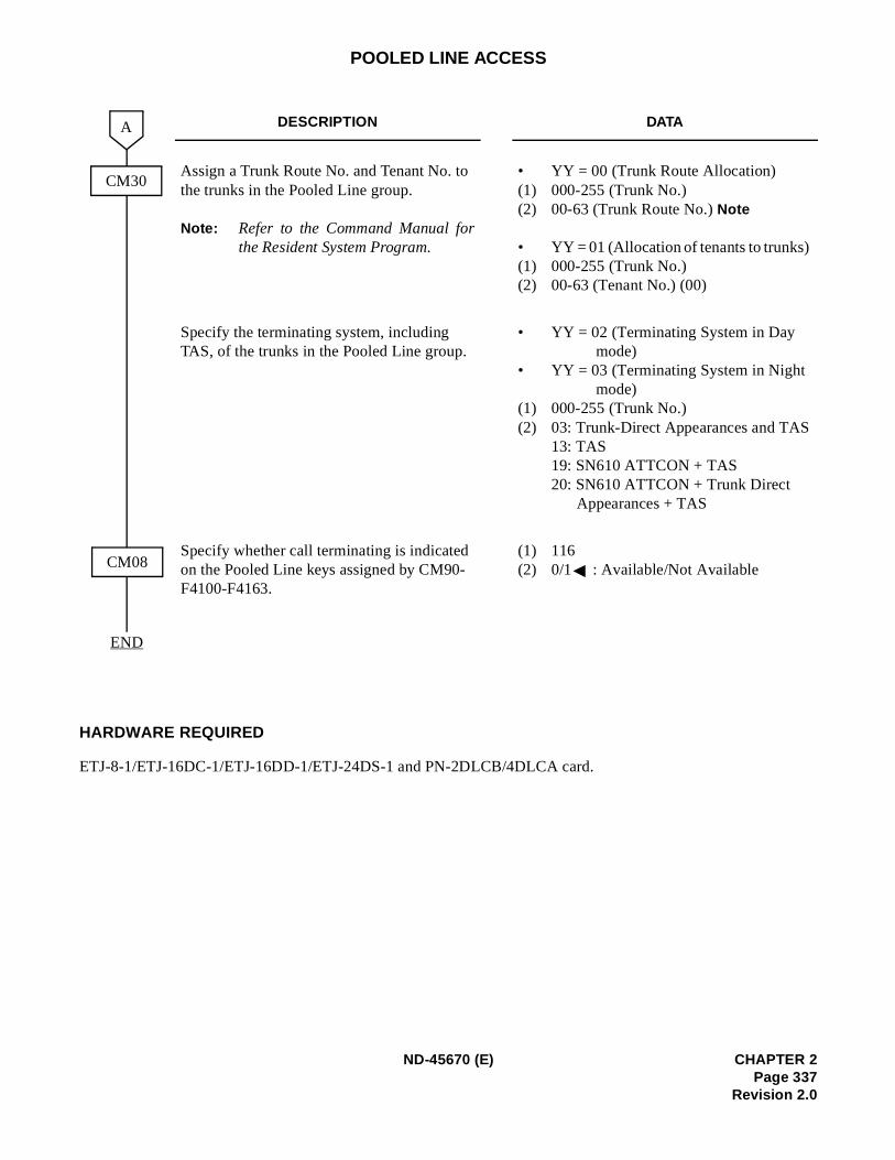
POOLED LINE ACCESS
HARDWARE REQUIRED
ETJ-8-1/ETJ-16DC-1/ETJ-16DD-1/ETJ-24DS-1 and PN-2DLCB/4DLCA card.
DESCRIPTION DATA
Assign a Trunk Route No. and Tenant No. to the trunks in the Pooled Line group.
Note: Refer to the Command Manual forthe Resident System Program.
• YY = 00 (Trunk Route Allocation) (1) 000-255 (Trunk No.) (2) 00-63 (Trunk Route No.) Note
• YY = 01 (Allocation of tenants to trunks) (1) 000-255 (Trunk No.) (2) 00-63 (Tenant No.) (00)
Specify the terminating system, including TAS, of the trunks in the Pooled Line group.
• YY = 02 (Terminating System in Day mode)
• YY = 03 (Terminating System in Night mode)
(1) 000-255 (Trunk No.) (2) 03: Trunk-Direct Appearances and TAS
13: TAS 19: SN610 ATTCON + TAS20: SN610 ATTCON + Trunk Direct
Appearances + TAS
Specify whether call terminating is indicated on the Pooled Line keys assigned by CM90-F4100-F4163.
(1) 116 (2) 0/1 : Available/Not Available
END
CM30
A
CM08
ND-45670 (E) CHAPTER 2Page 337
Revision 2.0
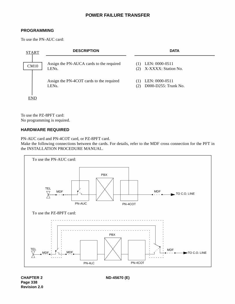
POWER FAILURE TRANSFER
PROGRAMMING
To use the PN-AUC card:
To use the PZ-8PFT card:No programming is required.
HARDWARE REQUIRED
PN-AUC card and PN-4COT card, or PZ-8PFT card.Make the following connections between the cards. For details, refer to the MDF cross connection for the PFT inthe INSTALLATION PROCEDURE MANUAL.
DESCRIPTION DATA
Assign the PN-AUCA cards to the required LENs.
(1) LEN: 0000-0511(2) X-XXXX: Station No.
Assign the PN-4COT cards to the required LENs.
(1) LEN: 0000-0511(2) D000-D255: Trunk No.
CM10
START
END
To use the PN-AUC card:
To use the PZ-8PFT card:
.. .. .MDFTO C.O. LINE
PBX
MDFTEL
... . .MDFTO C.O. LINE
PBX
MDFTEL
.MDF
..PN-4LC PN-4COT
PN-AUC PN-4COT
CHAPTER 2 ND-45670 (E)Page 338Revision 2.0
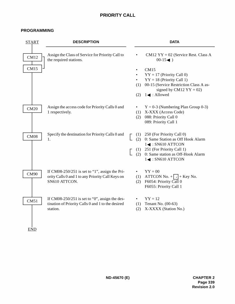
PRIORITY CALL
PROGRAMMING
DESCRIPTION DATA
Assign the Class of Service for Priority Call to the required stations.
• CM12 YY = 02 (Service Rest. Class A 00-15 )
• CM15 • YY = 17 (Priority Call 0) • YY = 18 (Priority Call 1) (1) 00-15 (Service Restriction Class A as-
signed by CM12 YY = 02) (2) 1 : Allowed
Assign the access code for Priority Calls 0 and 1 respectively.
• Y = 0-3 (Numbering Plan Group 0-3) (1) X-XXX (Access Code) (2) 088: Priority Call 0
089: Priority Call 1
Specify the destination for Priority Calls 0 and 1.
(1) 250 (For Priority Call 0) (2) 0: Same Station as Off Hook Alarm
1 : SN610 ATTCON (1) 251 (For Priority Call 1) (2) 0: Same station as Off-Hook Alarm
1 : SN610 ATTCON
If CM08-250/251 is set to “1”, assign the Pri-ority Calls 0 and 1 to any Priority Call Keys on SN610 ATTCON.
• YY = 00(1) ATTCON No. + + Key No.(2) F6054: Priority Call 0
F6055: Priority Call 1
If CM08-250/251 is set to “0”, assign the des-tination of Priority Calls 0 and 1 to the desired station.
• YY = 12(1) Tenant No. (00-63) (2) X-XXXX (Station No.)
CM51
START
CM08
CM12
CM15
END
CM20
CM90 ,
ND-45670 (E) CHAPTER 2Page 339
Revision 2.0
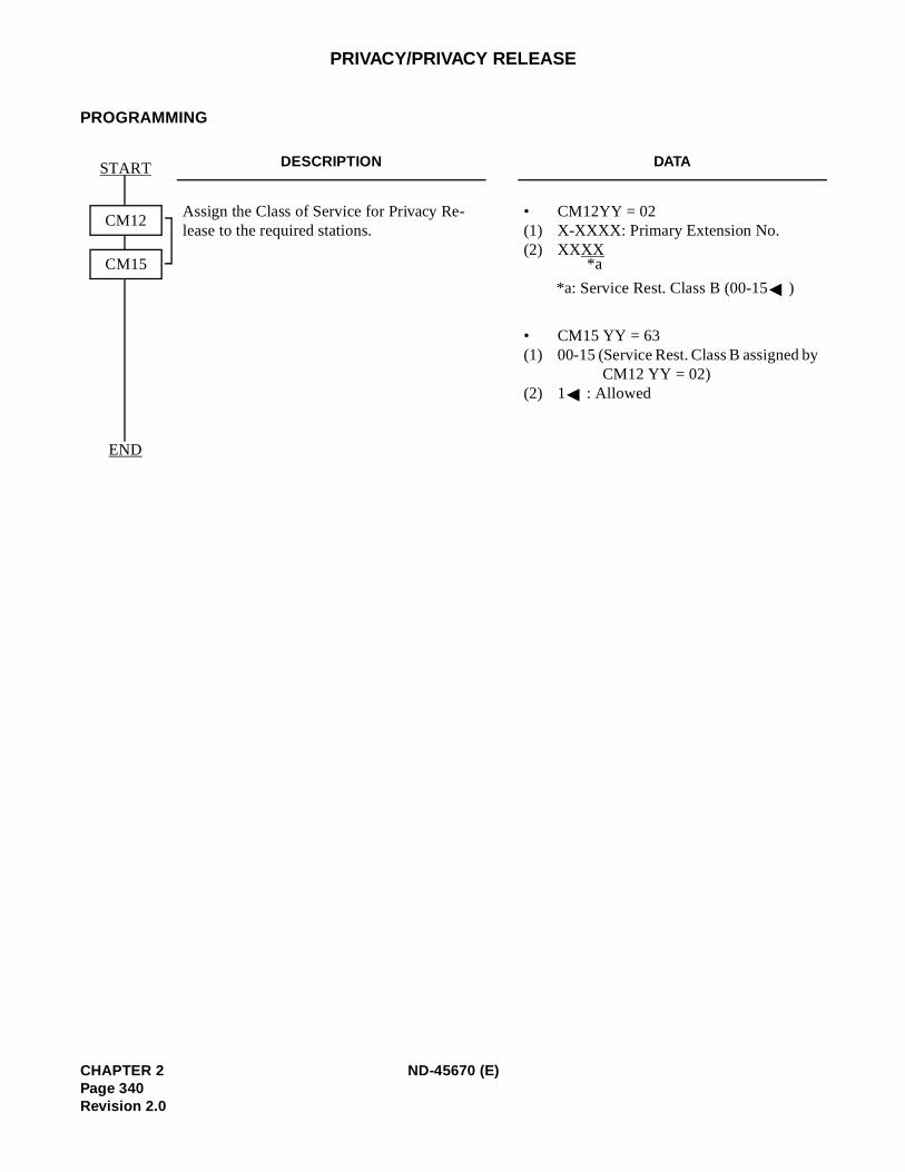
y
PRIVACY/PRIVACY RELEASE
PROGRAMMING
DESCRIPTION DATA
Assign the Class of Service for Privacy Re-lease to the required stations.
• CM12YY = 02(1) X-XXXX: Primary Extension No. (2) XXXX
*a: Service Rest. Class B (00-15 )
• CM15 YY = 63 (1) 00-15 (Service Rest. Class B assigned b
CM12 YY = 02) (2) 1 : Allowed
START
END
CM12
CM15 *a
CHAPTER 2 ND-45670 (E)Page 340Revision 2.0
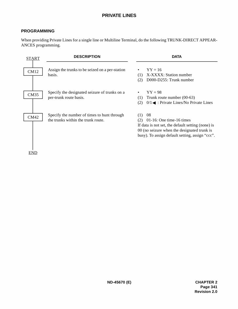
R-
PRIVATE LINES
PROGRAMMING
When providing Private Lines for a single line or Multiline Terminal, do the following TRUNK-DIRECT APPEAANCES programming.
DESCRIPTION DATA
Assign the trunks to be seized on a per-station basis.
• YY = 16(1) X-XXXX: Station number(2) D000-D255: Trunk number
Specify the designated seizure of trunks on a per-trunk route basis.
• YY = 98(1) Trunk route number (00-63) (2) 0/1 : Private Lines/No Private Lines
Specify the number of times to hunt through the trunks within the trunk route.
(1) 08(2) 01-16: One time-16 times If data is not set, the default setting (none) is00 (no seizure when the designated trunk is busy). To assign default setting, assign “ccc”.
START
END
CM12
CM35
CM42
ND-45670 (E) CHAPTER 2Page 341
Revision 2.0
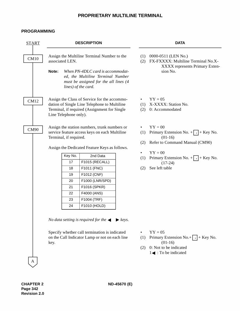
-
PROPRIETARY MULTILINE TERMINAL
PROGRAMMING
DESCRIPTION DATA
Assign the Multiline Terminal Number to the associated LEN.
Note: When PN-4DLC card is accommodat-ed, the Multiline Terminal Numbermust be assigned for the all lines (4lines) of the card.
(1) 0000-0511 (LEN No.) (2) FX-FXXXX: Multiline Terminal No.X-
XXXX represents Primary Extension No.
Assign the Class of Service for the accommo-dation of Single Line Telephone to Multiline Terminal, if required (Assignment for Single Line Telephone only).
• YY = 05(1) X-XXXX: Station No. (2) 0: Accommodated
Assign the station numbers, trunk numbers or service feature access keys on each Multiline Terminal, if required.
Assign the Dedicated Feature Keys as follows.
No data setting is required for the keys.
• YY = 00(1) Primary Extension No. + + Key No.
(01-16) (2) Refer to Command Manual (CM90)
• YY = 00 (1) Primary Extension No. + + Key No.
(17-24) (2) See left table
Specify whether call termination is indicated on the Call Indicator Lamp or not on each line key.
• YY = 05(1) Primary Extension No.+ + Key No.
(01-16) (2) 0: Not to be indicated
1 : To be indicated
CM10
START
CM12
CM90
A
Key No. 2nd Data
17
18
19
20
21
22
23
24
F1015 (RECALL)
F1011 (FNC)
F1012 (CNF)
F1000 (LNR/SPD)
F1016 (SPKR)
F4000 (ANS)
F1004 (TRF)
F1010 (HOLD)
,
,
,
CHAPTER 2 ND-45670 (E)Page 342Revision 2.0
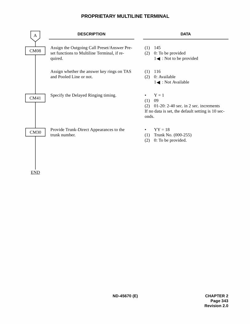
PROPRIETARY MULTILINE TERMINAL
DESCRIPTION DATA
Assign the Outgoing Call Preset/Answer Pre-set functions to Multiline Terminal, if re-quired.
(1) 145(2) 0: To be provided
1 : Not to be provided
Assign whether the answer key rings on TAS and Pooled Line or not.
(1) 116(2) 0: Available
1 : Not Available
Specify the Delayed Ringing timing. • Y = 1(1) 09(2) 01-20: 2-40 sec. in 2 sec. increments If no data is set, the default setting is 10 sec-onds.
Provide Trunk-Direct Appearances to the trunk number.
• YY = 18(1) Trunk No. (000-255) (2) 0: To be provided.
END
CM08
A
CM30
CM41
ND-45670 (E) CHAPTER 2Page 343
Revision 2.0
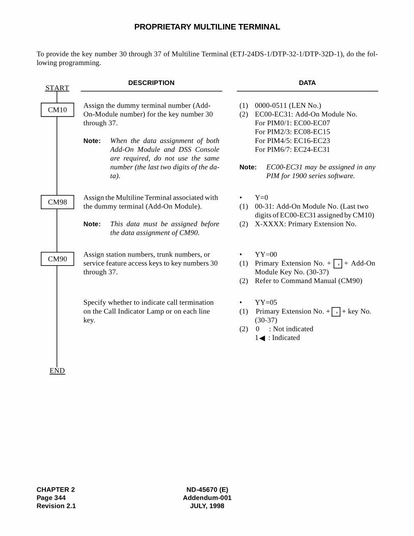
CHAPTER 2 ND-45670 (E)Page 344 Addendum-001Revision 2.1 JULY, 1998
PROPRIETARY MULTILINE TERMINAL
To provide the key number 30 through 37 of Multiline Terminal (ETJ-24DS-1/DTP-32-1/DTP-32D-1), do the fol-lowing programming.
DESCRIPTION DATA
Assign the dummy terminal number (Add-On-Module number) for the key number 30 through 37.
Note: When the data assignment of bothAdd-On Module and DSS Consoleare required, do not use the samenumber (the last two digits of the da-ta).
(1) 0000-0511 (LEN No.) (2) EC00-EC31: Add-On Module No.
For PIM0/1: EC00-EC07 For PIM2/3: EC08-EC15 For PIM4/5: EC16-EC23 For PIM6/7: EC24-EC31
Note: EC00-EC31 may be assigned in anyPIM for 1900 series software.
Assign the Multiline Terminal associated with the dummy terminal (Add-On Module).
Note: This data must be assigned beforethe data assignment of CM90.
• Y=0(1) 00-31: Add-On Module No. (Last two
digits of EC00-EC31 assigned by CM10) (2) X-XXXX: Primary Extension No.
Assign station numbers, trunk numbers, or service feature access keys to key numbers 30 through 37.
• YY=00 (1) Primary Extension No. + + Add-On
Module Key No. (30-37) (2) Refer to Command Manual (CM90)
Specify whether to indicate call termination on the Call Indicator Lamp or on each line key.
• YY=05(1) Primary Extension No. + + key No.
(30-37) (2) 0 : Not indicated
1 : Indicated
START
END
CM10
CM98
CM90 ,
,
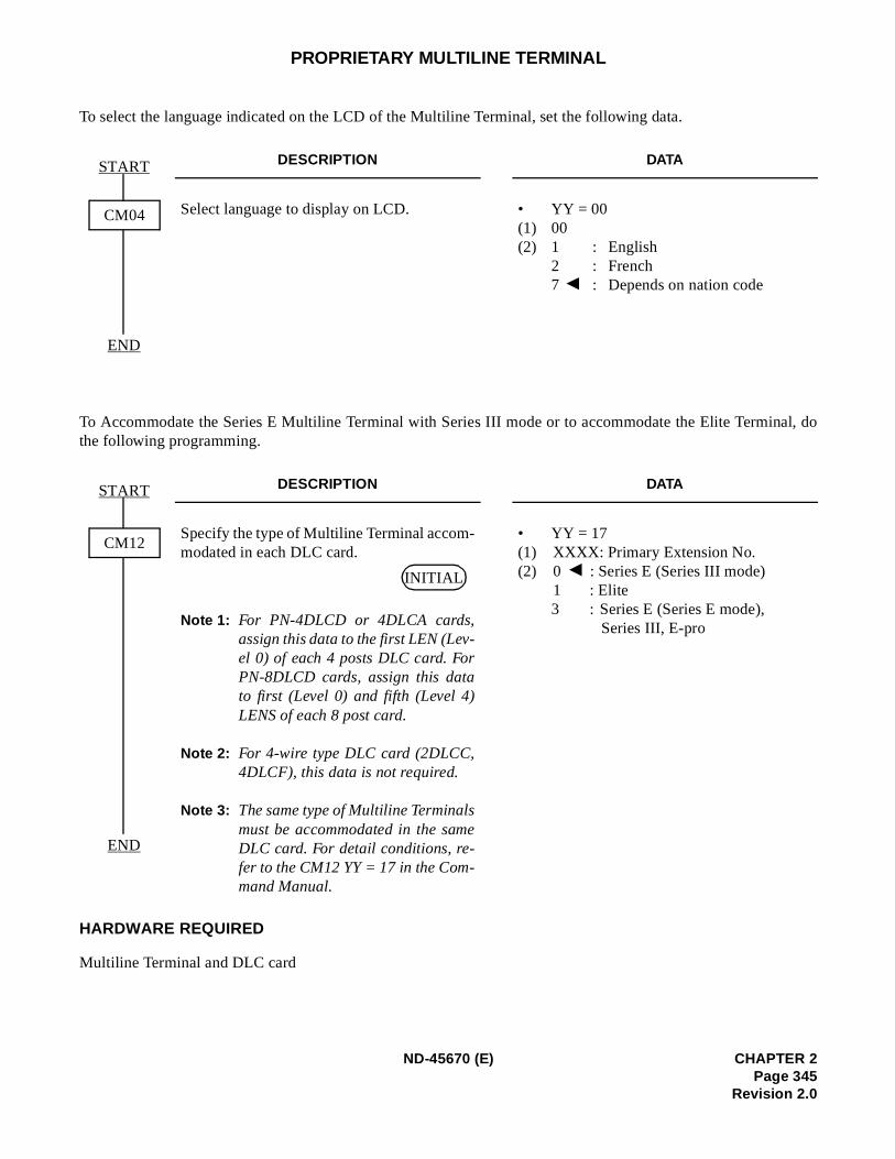
al, do
PROPRIETARY MULTILINE TERMINAL
To select the language indicated on the LCD of the Multiline Terminal, set the following data.
To Accommodate the Series E Multiline Terminal with Series III mode or to accommodate the Elite Terminthe following programming.
HARDWARE REQUIRED
Multiline Terminal and DLC card
DESCRIPTION DATA
Select language to display on LCD. • YY = 00(1) 00(2) 1 : English
2 : French7 : Depends on nation code
DESCRIPTION DATA
Specify the type of Multiline Terminal accom-modated in each DLC card.
Note 1: For PN-4DLCD or 4DLCA cards,assign this data to the first LEN (Lev-el 0) of each 4 posts DLC card. ForPN-8DLCD cards, assign this datato first (Level 0) and fifth (Level 4)LENS of each 8 post card.
Note 2: For 4-wire type DLC card (2DLCC,4DLCF), this data is not required.
Note 3: The same type of Multiline Terminalsmust be accommodated in the sameDLC card. For detail conditions, re-fer to the CM12 YY = 17 in the Com-mand Manual.
• YY = 17(1) XXXX: Primary Extension No.(2) 0 : Series E (Series III mode)
1 : Elite3 : Series E (Series E mode),
Series III, E-pro
START
END
CM04
START
END
CM12
INITIAL
ND-45670 (E) CHAPTER 2Page 345
Revision 2.0
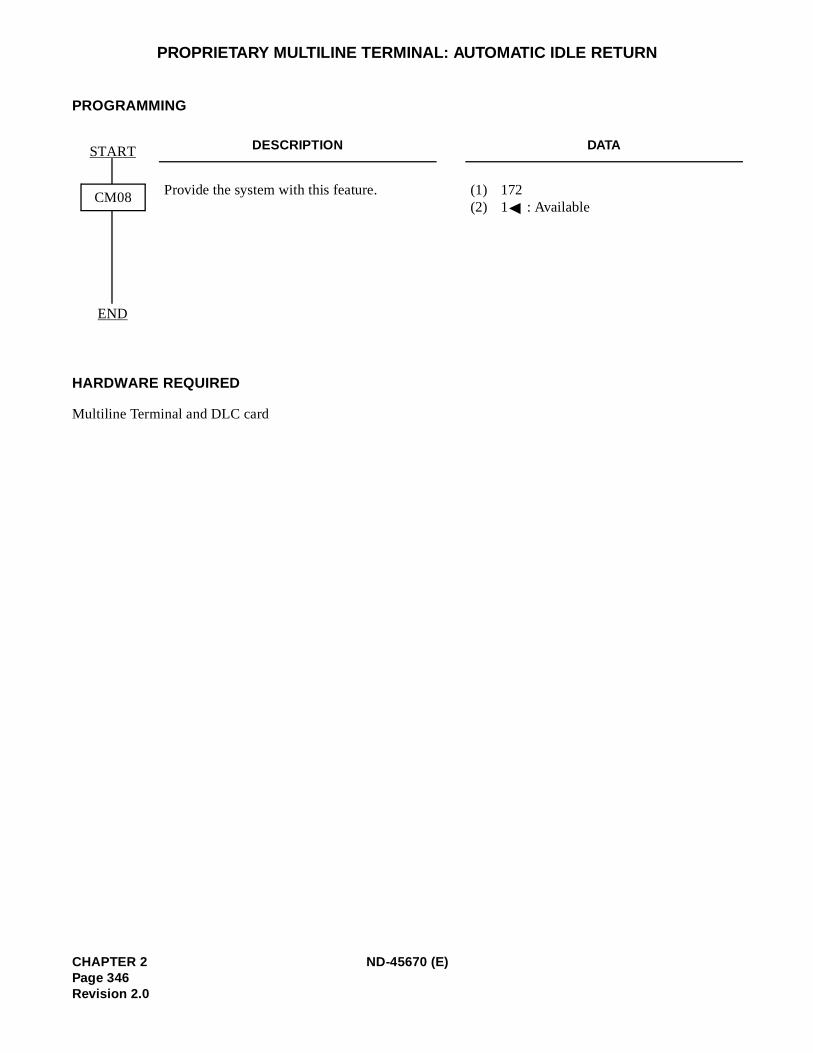
PROPRIETARY MULTILINE TERMINAL: AUTOMATIC IDLE RETURN
PROGRAMMING
HARDWARE REQUIRED
Multiline Terminal and DLC card
DESCRIPTION DATA
Provide the system with this feature. (1) 172 (2) 1 : Available
START
END
CM08
CHAPTER 2 ND-45670 (E)Page 346Revision 2.0
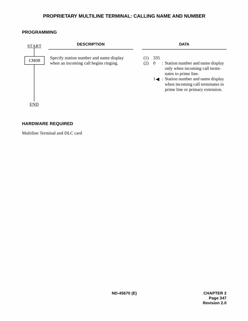
PROPRIETARY MULTILINE TERMINAL: CALLING NAME AND NUMBER
PROGRAMMING
HARDWARE REQUIRED
Multiline Terminal and DLC card
DESCRIPTION DATA
Specify station number and name display when an incoming call begins ringing.
(1) 335 (2) 0 : Station number and name display
only when incoming call termi-nates to prime line.
1 : Station number and name displaywhen incoming call terminates to prime line or primary extension.
START
END
CM08
ND-45670 (E) CHAPTER 2Page 347
Revision 2.0
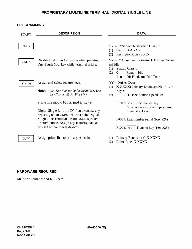
PROPRIETARY MULTILINE TERMINAL: DIGITAL SINGLE LINE
PROGRAMMING
HARDWARE REQUIRED
Multiline Terminal and DLC card
DESCRIPTION DATA
YY = 07:Service Restriction Class C(1) Station X-XXXX(2) Restriction Class 00-15
Disable Dial Tone Activation when pressing One-Touch Spd. key while terminal is idle.
YY = 87:One-Touch activates DT when Termi-nal Idle(1) Station Class C(2) 0 : Remain Idle
1 : Off Hook and Dial Tone
Assign and delete feature keys.
Note: Use Key Number 20 for Redial key. UseKey Number 23 for Flash key.
Prime line should be assigned to Key 9.
Digital Single Line is a Dterm and can use any key assigned in CM90. However, the Digital Single Line Terminal has no LEDs, speaker, or microphone. Assign any features that can be used without these devices.
YY = 00:Key Data(1) X-XXXX: Primary Extension No. + +
Key #.(2) F1100 - F1199: Station Speed Dial
F1012: Conference keyThis key is required to program speed dial keys.
F0069: Last number redial (Key #20)
F1004: Transfer key (Key #23)
Assign prime line to primary extension. (1) Primary Extension #: X-XXXX(2) Prime Line: X-XXXX
CM12
CM15
START
CM93
CM90,
CNF
TRF
CHAPTER 2 ND-45670 (E)Page 348Revision 2.0
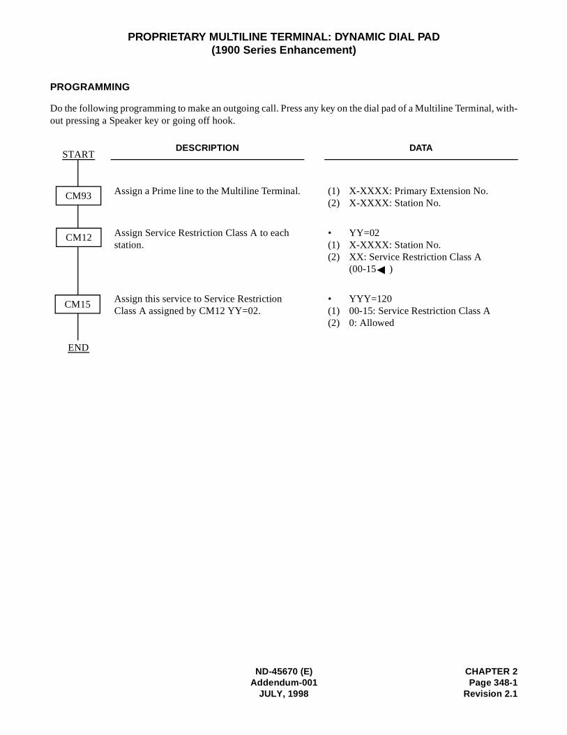
ND-45670 (E) CHAPTER 2Addendum-001 Page 348-1
JULY, 1998 Revision 2.1
PROPRIETARY MULTILINE TERMINAL: DYNAMIC DIAL PAD(1900 Series Enhancement)
PROGRAMMING
Do the following programming to make an outgoing call. Press any key on the dial pad of a Multiline Terminal, with-out pressing a Speaker key or going off hook.
DESCRIPTION DATA
Assign a Prime line to the Multiline Terminal. (1) X-XXXX: Primary Extension No. (2) X-XXXX: Station No.
Assign Service Restriction Class A to each station.
• YY=02(1) X-XXXX: Station No.(2) XX: Service Restriction Class A
(00-15 )
Assign this service to Service Restriction Class A assigned by CM12 YY=02.
• YYY=120(1) 00-15: Service Restriction Class A(2) 0: Allowed
START
END
CM12
CM93
CM15

CHAPTER 2 ND-45670 (E)Page 348-2 Addendum-001Revision 2.1 JULY, 1998
This page is for your notes.
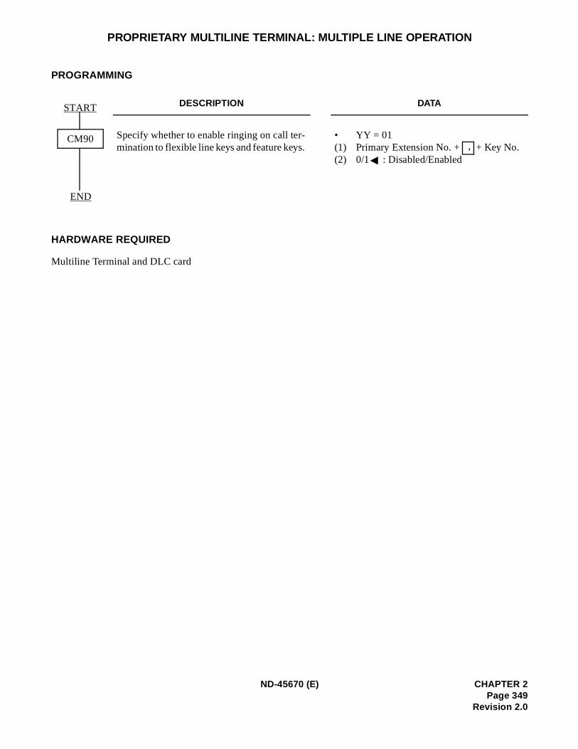
PROPRIETARY MULTILINE TERMINAL: MULTIPLE LINE OPERATION
PROGRAMMING
HARDWARE REQUIRED
Multiline Terminal and DLC card
DESCRIPTION DATA
Specify whether to enable ringing on call ter-mination to flexible line keys and feature keys.
• YY = 01(1) Primary Extension No. + + Key No. (2) 0/1 : Disabled/Enabled
START
END
CM90,
ND-45670 (E) CHAPTER 2Page 349
Revision 2.0
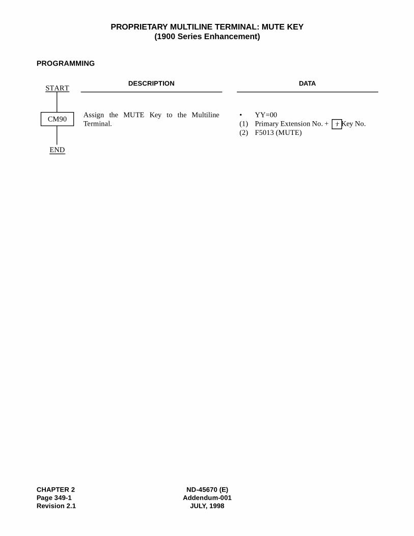
CHAPTER 2 ND-45670 (E)Page 349-1 Addendum-001Revision 2.1 JULY, 1998
PROPRIETARY MULTILINE TERMINAL: MUTE KEY(1900 Series Enhancement)
PROGRAMMING
DESCRIPTION DATA
Assign the MUTE Key to the MultilineTerminal.
• YY=00(1) Primary Extension No. + + Key No.(2) F5013 (MUTE)
START
END
CM90 ,

ND-45670 (E) CHAPTER 2Addendum-001 Page 349-2
JULY, 1998 Revision 2.1
This page is for your notes.
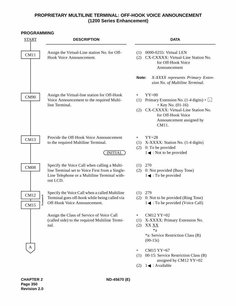
PROPRIETARY MULTILINE TERMINAL: OFF-HOOK VOICE ANNOUNCEMENT (1200 Series Enhancement)
PROGRAMMING
DESCRIPTION DATA
Assign the Virtual-Line station No. for Off-Hook Voice Announcement.
(1) 0000-0255: Virtual LEN(2) CX-CXXXX: Virtual-Line Station No.
for Off-Hook Voice Announcement
Note: X-XXXX represents Primary Exten-sion No. of Multiline Terminal.
Assign the Virtual-line station for Off-Hook Voice Announcement to the required Multi-line Terminal.
• YY=00(1) Primary Extension No. (1-4 digits) +
+ Key No. (01-16)(2) CX-CXXXX: Virtual-Line Station No.
for Off-Hook Voice Announcement assigned by CM11.
Provide the Off-Hook Voice Announcement to the required Multiline Terminal.
• YY=28(1) X-XXXX: Station No. (1-4 digits)(2) 0: To be provided
1 : Not to be provided
Specify the Voice Call when calling a Multi-line Terminal set to Voice First from a Single-Line Telephone or a Multiline Terminal with-out LCD.
(1) 270(2) 0: Not provided (Busy Tone)
1 : To be provided
Specify the Voice Call when a called Multiline Terminal goes off-hook while being called via Off-Hook Voice Announcement.
(1) 279(2) 0: Not to be provided (Ring Tone)
1 : To be provided (Voice Call)
Assign the Class of Service of Voice Call (called side) to the required Multiline Termi-nal.
• CM12 YY=02(1) X-XXXX: Primary Extension No.(2) XX XX
*a *a: Service Restriction Class (B) (00-15t)
• CM15 YY=67(1) 00-15: Service Restriction Class (B)
assigned by CM12 YY=02(2) 1 : Available
START
CM11
A
CM90
CM13
CM08
CM12
CM15
,
INITIAL
CHAPTER 2 ND-45670 (E)Page 350Revision 2.0
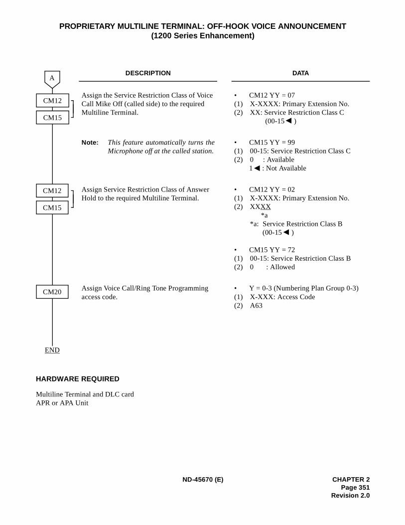
PROPRIETARY MULTILINE TERMINAL: OFF-HOOK VOICE ANNOUNCEMENT (1200 Series Enhancement)
HARDWARE REQUIRED
Multiline Terminal and DLC cardAPR or APA Unit
DESCRIPTION DATA
Assign the Service Restriction Class of Voice Call Mike Off (called side) to the required Multiline Terminal.
• CM12 YY = 07(1) X-XXXX: Primary Extension No.(2) XX: Service Restriction Class C
(00-15 )
Note: This feature automatically turns theMicrophone off at the called station.
• CM15 YY = 99(1) 00-15: Service Restriction Class C (2) 0 : Available
1 : Not Available
Assign Service Restriction Class of Answer Hold to the required Multiline Terminal.
• CM12 YY = 02(1) X-XXXX: Primary Extension No.(2) XXXX
*a*a: Service Restriction Class B
(00-15 )
• CM15 YY = 72(1) 00-15: Service Restriction Class B(2) 0 : Allowed
Assign Voice Call/Ring Tone Programming access code.
• Y = 0-3 (Numbering Plan Group 0-3)(1) X-XXX: Access Code(2) A63
CM12
A
END
CM12
CM15
CM20
CM15
ND-45670 (E) CHAPTER 2Page 351
Revision 2.0
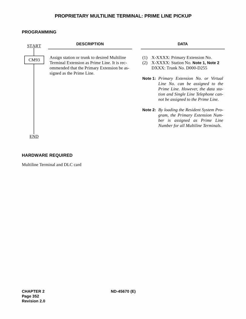
-
-
PROPRIETARY MULTILINE TERMINAL: PRIME LINE PICKUP
PROGRAMMING
HARDWARE REQUIRED
Multiline Terminal and DLC card
DESCRIPTION DATA
Assign station or trunk to desired Multiline Terminal Extension as Prime Line. It is rec-ommended that the Primary Extension be as-signed as the Prime Line.
(1) X-XXXX: Primary Extension No. (2) X-XXXX: Station No. Note 1, Note 2
DXXX: Trunk No. D000-D255
Note 1: Primary Extension No. or VirtualLine No. can be assigned to thePrime Line. However, the data sta-tion and Single Line Telephone cannot be assigned to the Prime Line.
Note 2: By loading the Resident System Program, the Primary Extension Num-ber is assigned as Prime LineNumber for all Multiline Terminals.
START
END
CM93
CHAPTER 2 ND-45670 (E)Page 352Revision 2.0
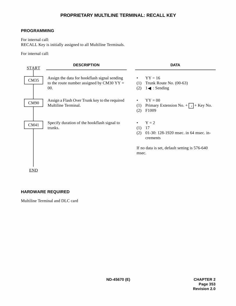
PROPRIETARY MULTILINE TERMINAL: RECALL KEY
PROGRAMMING
For internal call: RECALL Key is initially assigned to all Multiline Terminals.
For internal call:
HARDWARE REQUIRED
Multiline Terminal and DLC card
DESCRIPTION DATA
Assign the data for hookflash signal sending to the route number assigned by CM30 YY = 00.
• YY = 16(1) Trunk Route No. (00-63)(2) 1 : Sending
Assign a Flash Over Trunk key to the required Multiline Terminal.
• YY = 00(1) Primary Extension No. + + Key No.(2) F1009
Specify duration of the hookflash signal to trunks.
• Y = 2(1) 17(2) 01-30: 128-1920 msec. in 64 msec. in-
crements
If no data is set, default setting is 576-640 msec.
START
END
CM35
CM90
CM41
,
ND-45670 (E) CHAPTER 2Page 353
Revision 2.0
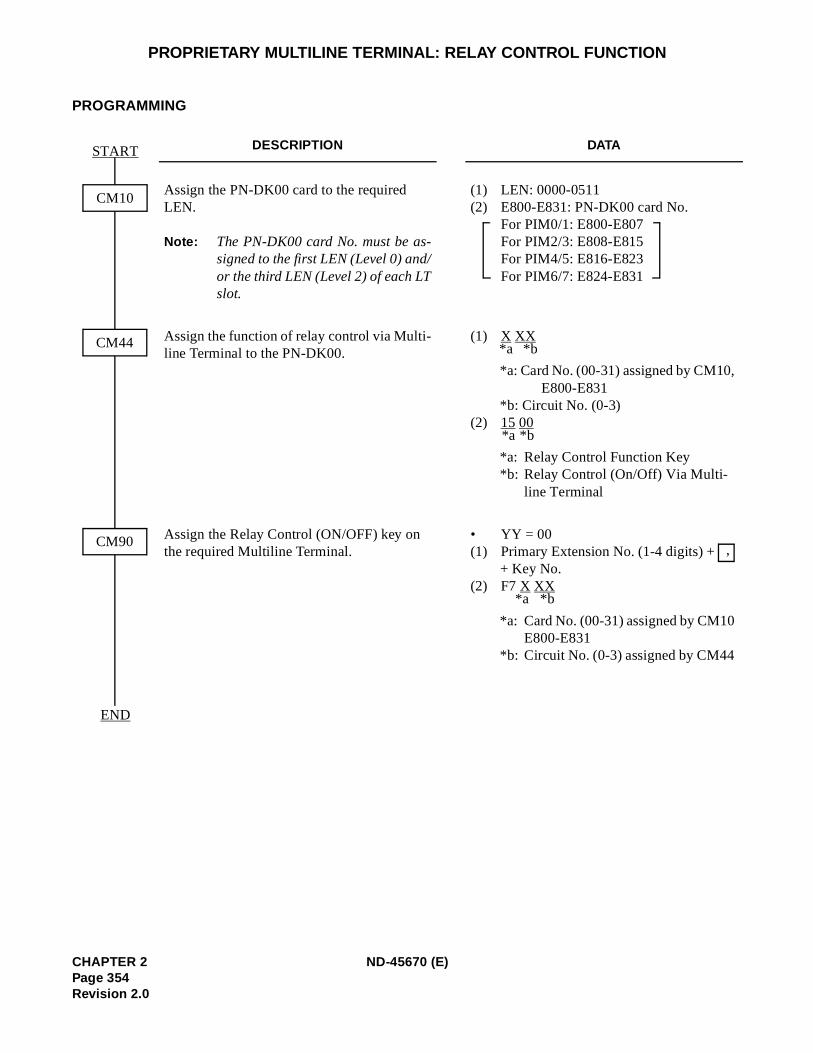
PROPRIETARY MULTILINE TERMINAL: RELAY CONTROL FUNCTION
PROGRAMMING
DESCRIPTION DATA
Assign the PN-DK00 card to the required LEN.
Note: The PN-DK00 card No. must be as-signed to the first LEN (Level 0) and/or the third LEN (Level 2) of each LTslot.
(1) LEN: 0000-0511(2) E800-E831: PN-DK00 card No.
For PIM0/1: E800-E807 For PIM2/3: E808-E815 For PIM4/5: E816-E823 For PIM6/7: E824-E831
Assign the function of relay control via Multi-line Terminal to the PN-DK00.
(1) X XX
*a: Card No. (00-31) assigned by CM10,E800-E831
*b: Circuit No. (0-3) (2) 15 00
*a: Relay Control Function Key*b: Relay Control (On/Off) Via Multi-
line Terminal
Assign the Relay Control (ON/OFF) key on the required Multiline Terminal.
• YY = 00(1) Primary Extension No. (1-4 digits) +
+ Key No.(2) F7 X XX
*a: Card No. (00-31) assigned by CM10E800-E831
*b: Circuit No. (0-3) assigned by CM44
START
END
CM10
CM90
CM44 *a *b
*a *b
,
*a *b
CHAPTER 2 ND-45670 (E)Page 354Revision 2.0
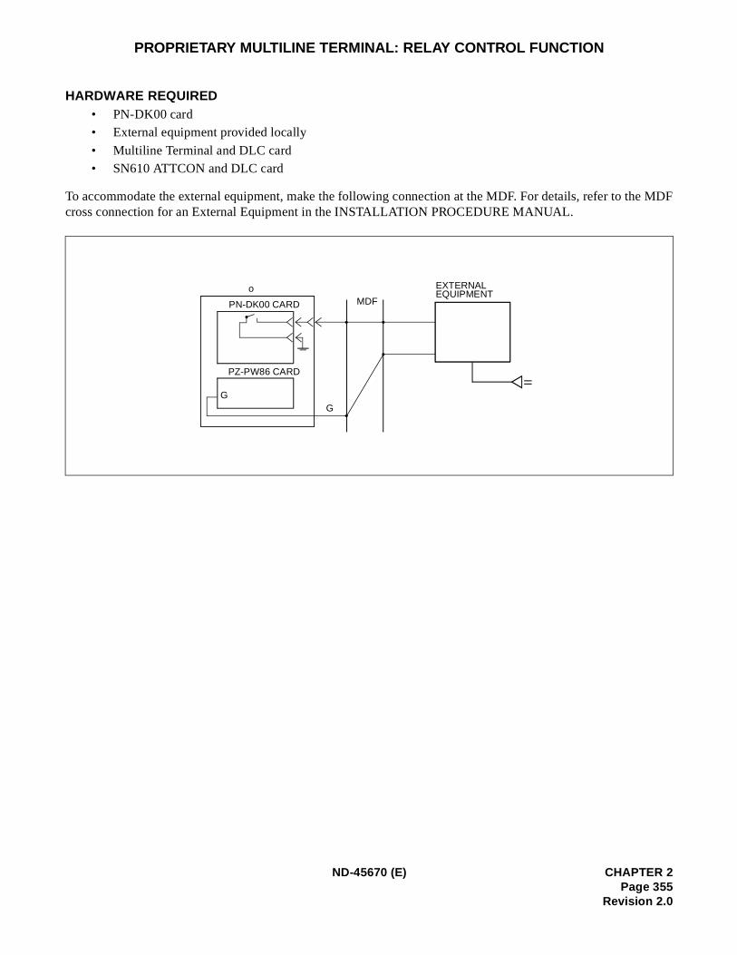
PROPRIETARY MULTILINE TERMINAL: RELAY CONTROL FUNCTION
HARDWARE REQUIRED • PN-DK00 card• External equipment provided locally
• Multiline Terminal and DLC card • SN610 ATTCON and DLC card
To accommodate the external equipment, make the following connection at the MDF. For details, refer to the MDFcross connection for an External Equipment in the INSTALLATION PROCEDURE MANUAL.
o
PN-DK00 CARD
PZ-PW86 CARD
G
MDF
EXTERNALEQUIPMENT
G
ND-45670 (E) CHAPTER 2Page 355
Revision 2.0
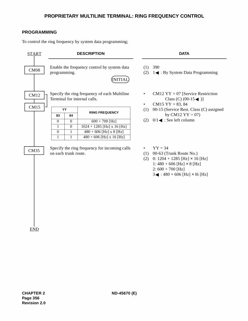
PROPRIETARY MULTILINE TERMINAL: RING FREQUENCY CONTROL
PROGRAMMING
To control the ring frequency by system data programming;
DESCRIPTION DATA
Enable the frequency control by system data programming.
(1) 390 (2) 1 : By System Data Programming
Specify the ring frequency of each Multiline Terminal for internal calls.
• CM12 YY = 07 [Service Restriction Class (C) (00-15 )]
• CM15 YY = 83, 84(1) 00-15 (Service Rest. Class (C) assigned
by CM12 YY = 07) (2) 0/1 : See left column
Specify the ring frequency for incoming calls on each trunk route.
• YY = 34(1) 00-63 (Trunk Route No.) (2) 0: 1204 + 1285 [Hz] × 16 [Hz]
1: 480 + 606 [Hz] × 8 [Hz]2: 600 + 700 [Hz] 3 : 480 + 606 [Hz] × l6 [Hz]
START
END
CM12
CM15
CM08
CM35
INITIAL
YYRING FREQUENCY
83 84
0 0 600 + 700 [Hz]1 0 1024 + 1285 [Hz] x 16 [Hz]0 1 480 + 606 [Hz] x 8 [Hz]1 1 480 + 606 [Hz] x 16 [Hz]
CHAPTER 2 ND-45670 (E)Page 356Revision 2.0
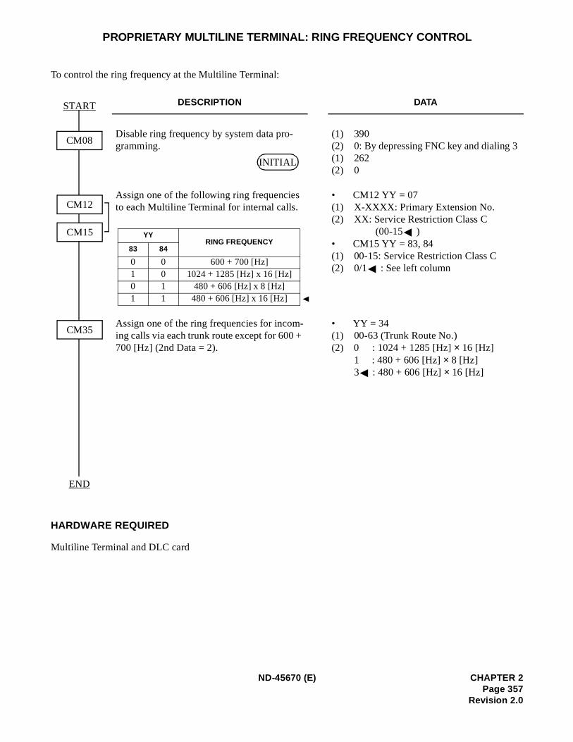
PROPRIETARY MULTILINE TERMINAL: RING FREQUENCY CONTROL
To control the ring frequency at the Multiline Terminal:
HARDWARE REQUIRED
Multiline Terminal and DLC card
DESCRIPTION DATA
Disable ring frequency by system data pro-gramming.
(1) 390 (2) 0: By depressing FNC key and dialing 3(1) 262(2) 0
Assign one of the following ring frequencies to each Multiline Terminal for internal calls.
• CM12 YY = 07(1) X-XXXX: Primary Extension No.(2) XX: Service Restriction Class C
(00-15 )• CM15 YY = 83, 84(1) 00-15: Service Restriction Class C(2) 0/1 : See left column
Assign one of the ring frequencies for incom-ing calls via each trunk route except for 600 + 700 [Hz] (2nd Data = 2).
• YY = 34(1) 00-63 (Trunk Route No.) (2) 0 : 1024 + 1285 [Hz] × 16 [Hz]
1 : 480 + 606 [Hz] × 8 [Hz]3 : 480 + 606 [Hz] × 16 [Hz]
START
END
CM12
CM15
CM08
CM35
INITIAL
YYRING FREQUENCY
83 84
0 0 600 + 700 [Hz]1 0 1024 + 1285 [Hz] x 16 [Hz]0 1 480 + 606 [Hz] x 8 [Hz]1 1 480 + 606 [Hz] x 16 [Hz]
ND-45670 (E) CHAPTER 2Page 357
Revision 2.0
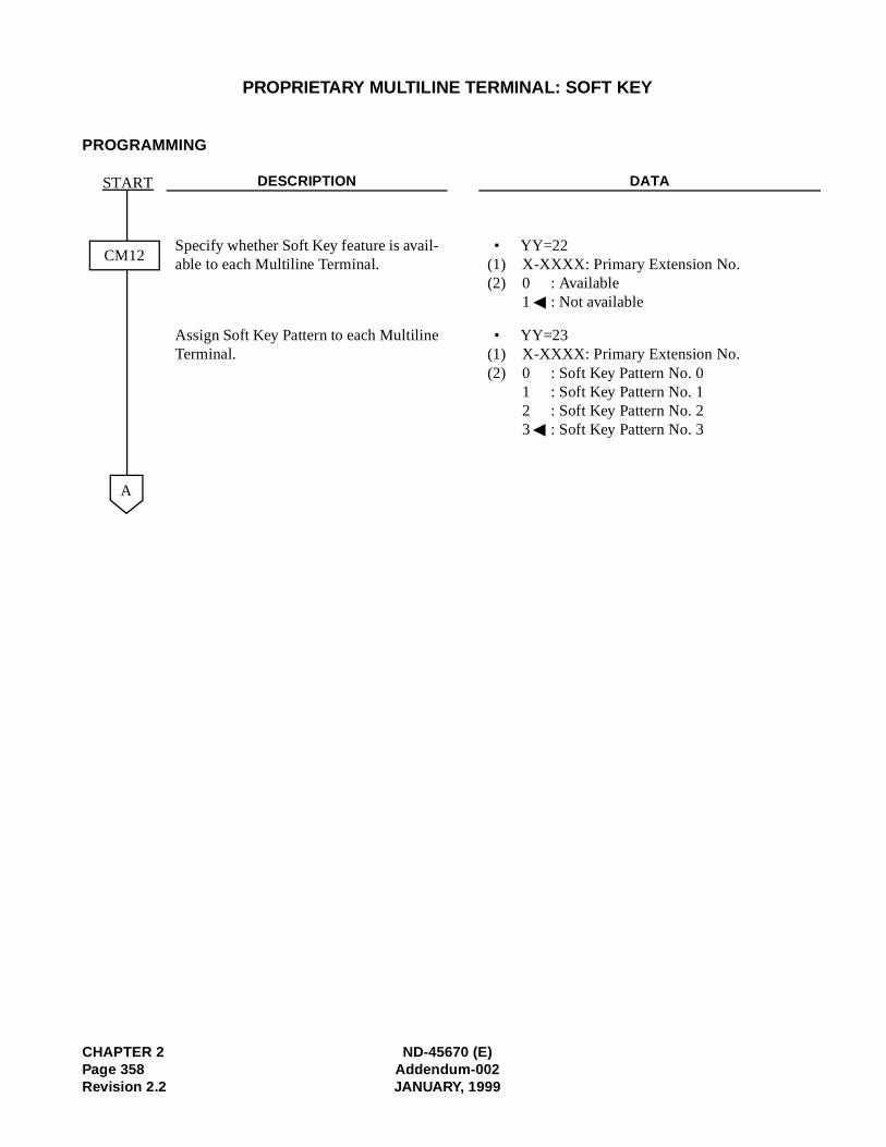
PROPRIETARY MULTILINE TERMINAL: SOFT KEY
PROGRAMMING
DESCRIPTION DATA
Specify whether Soft Key feature is avail-able to each Multiline Terminal.
• YY=22(1) X-XXXX: Primary Extension No. (2) 0 : Available
1 : Not available
Assign Soft Key Pattern to each MultilineTerminal.
• YY=23(1) X-XXXX: Primary Extension No. (2) 0 : Soft Key Pattern No. 0
1 : Soft Key Pattern No. 12 : Soft Key Pattern No. 23 : Soft Key Pattern No. 3
CM12
START
A
CHAPTER 2 ND-45670 (E)Page 358 Addendum-002Revision 2.2 JANUARY, 1999
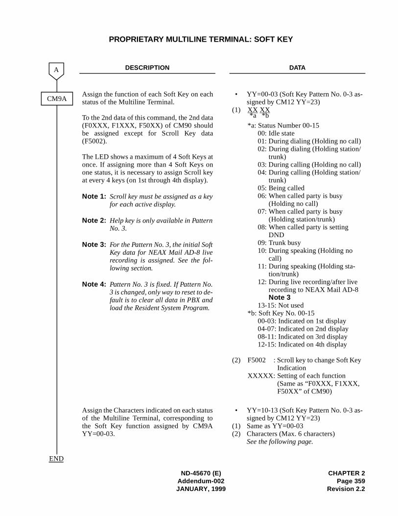
-
-
PROPRIETARY MULTILINE TERMINAL: SOFT KEY
DESCRIPTION DATA
Assign the function of each Soft Key on eachstatus of the Multiline Terminal.
To the 2nd data of this command, the 2nd data(F0XXX, F1XXX, F50XX) of CM90 shouldbe assigned except for Scroll Key data(F5002).
The LED shows a maximum of 4 Soft Keys atonce. If assigning more than 4 Soft Keys onone status, it is necessary to assign Scroll keyat every 4 keys (on 1st through 4th display).
Note 1: Scroll key must be assigned as a keyfor each active display.
Note 2: Help key is only available in PatternNo. 3.
Note 3: For the Pattern No. 3, the initial SoftKey data for NEAX Mail AD-8 liverecording is assigned. See the fol-lowing section.
Note 4: Pattern No. 3 is fixed. If Pattern No.3 is changed, only way to reset to de-fault is to clear all data in PBX andload the Resident System Program.
• YY=00-03 (Soft Key Pattern No. 0-3 assigned by CM12 YY=23)
(1) XX XX
*a: Status Number 00-1500: Idle state01: During dialing (Holding no call) 02: During dialing (Holding station/
trunk)03: During calling (Holding no call) 04: During calling (Holding station/
trunk) 05: Being called 06: When called party is busy
(Holding no call)07: When called party is busy
(Holding station/trunk) 08: When called party is setting
DND09: Trunk busy10: During speaking (Holding no
call) 11: During speaking (Holding sta-
tion/trunk)12: During live recording/after live
recording to NEAX Mail AD-8Note 3
13-15: Not used*b: Soft Key No. 00-15
00-03: Indicated on 1st display04-07: Indicated on 2nd display 08-11: Indicated on 3rd display12-15: Indicated on 4th display
(2) F5002 : Scroll key to change Soft KeyIndication
XXXXX: Setting of each function (Same as “F0XXX, F1XXX, F50XX” of CM90)
Assign the Characters indicated on each statusof the Multiline Terminal, corresponding tothe Soft Key function assigned by CM9AYY=00-03.
• YY=10-13 (Soft Key Pattern No. 0-3 assigned by CM12 YY=23)
(1) Same as YY=00-03(2) Characters (Max. 6 characters)
See the following page.
CM9A
A
END
*a *b
ND-45670 (E) CHAPTER 2Addendum-002 Page 359JANUARY, 1999 Revision 2.2
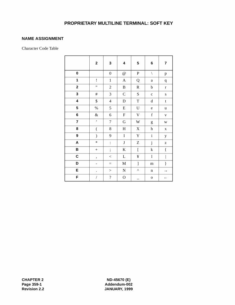
CHAPTER 2 ND-45670 (E)Page 359-1 Addendum-002Revision 2.2 JANUARY, 1999
PROPRIETARY MULTILINE TERMINAL: SOFT KEY
NAME ASSIGNMENT
Character Code Table
2 3 4 5 6 7
0 0 @ P \ p
1 ! 1 A Q a q
2 ” 2 B R b r
3 # 3 C S c s
4 $ 4 D T d t
5 % 5 E U e u
6 & 6 F V f v
7 ’ 7 G W g w
8 ( 8 H X h x
9 ) 9 I Y i y
A * : J Z j z
B + ; K [ k
C , < L ¥ l |
D - = M ] m
E . > N ^ n →F / ? O _ o ←
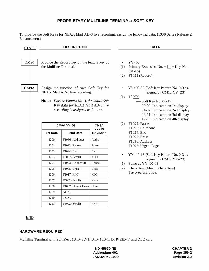
ND-45670 (E) CHAPTER 2Addendum-002 Page 359-2JANUARY, 1999 Revision 2.2
PROPRIETARY MULTILINE TERMINAL: SOFT KEY
To provide the Soft Keys for NEAX Mail AD-8 live recording, assign the following data. (1900 Series Release 2Enhancement)
HARDWARE REQUIRED
Multiline Terminal with Soft Keys (DTP-8D-1, DTP-16D-1, DTP-32D-1) and DLC card
DESCRIPTION DATA
Provide the Record key on the feature key ofthe Muliline Terminal.
• YY=00(1) Primary Extension No. + + Key No.
(01-16)(2) F1091 (Record)
Assign the function of each Soft Key forNEAX Mail AD-8 live recording.
Note: For the Pattern No. 3, the initial SoftKey data for NEAX Mail AD-8 liverecording is assigned as follows.
• YY=00-03 (Soft Key Pattern No. 0-3 as-signed by CM12 YY=23)
(1) 12 XXSoft Key No. 00-1500-03: Indicated on 1st display04-07: Indicated on 2nd display08-11: Indicated on 3rd display12-15: Indicated on 4th display
(2) F1092: PauseF1093: Re-recordF1094: EndF1095: EraseF1096: AddressF1097: Urgent Page
• YY=10-13 (Soft Key Pattern No. 0-3 as-signed by CM12 YY=23)
(1) Same as YY=00-03(2) Characters (Max. 6 characters)
See previous page.
CM90
START
CM9A
END
,
CM9A YY=03 CM9A YY=13
Indication1st Data 2nd Data
1200 F1096 (Address) Addrs
1201 F1092 (Pause) Pause
1202 F1094 (End) End
1203 F5002 (Scroll) >>>>
1204 F1093 (Re-record) ReRec
1205 F1095 (Erase) Erase
1206 F1017 (MIC) MIC
1207 F5002 (Scroll) >>>>
1208 F1097 (Urgent Page) Urgnt
1209 NONE
1210 NONE
1211 F5002 (Scroll) >>>>
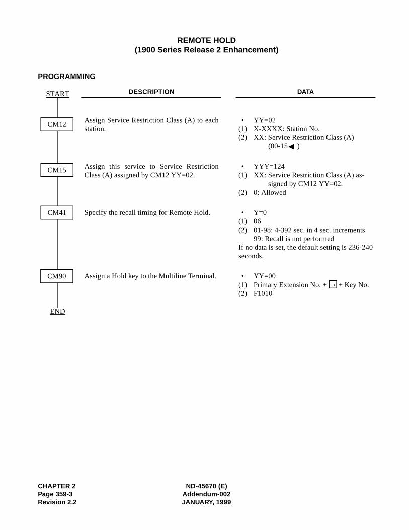
CHAPTER 2 ND-45670 (E)Page 359-3 Addendum-002Revision 2.2 JANUARY, 1999
REMOTE HOLD(1900 Series Release 2 Enhancement)
PROGRAMMING
DESCRIPTION DATA
Assign Service Restriction Class (A) to eachstation.
• YY=02(1) X-XXXX: Station No. (2) XX: Service Restriction Class (A)
(00-15 )
Assign this service to Service RestrictionClass (A) assigned by CM12 YY=02.
• YYY=124(1) XX: Service Restriction Class (A) as-
signed by CM12 YY=02.(2) 0: Allowed
Specify the recall timing for Remote Hold. • Y=0(1) 06(2) 01-98: 4-392 sec. in 4 sec. increments
99: Recall is not performedIf no data is set, the default setting is 236-240seconds.
Assign a Hold key to the Multiline Terminal. • YY=00(1) Primary Extension No. + + Key No.(2) F1010
START
CM41
CM12
END
CM15
CM90,

ND-45670 (E) CHAPTER 2Addendum-002 Page 359-4JANUARY, 1999 Revision 2.2
This page is for your notes.

RESIDENT SYSTEM PROGRAM
PROGRAMMING
No programming is required. (For the details of programmed system data, refer to the Command Manual.)
CHAPTER 2 ND-45670 (E)Page 360Revision 2.0
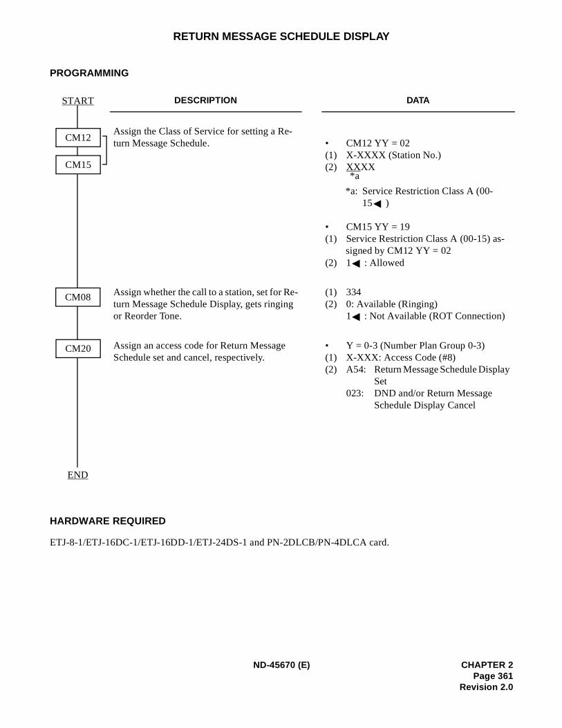
y
RETURN MESSAGE SCHEDULE DISPLAY
PROGRAMMING
HARDWARE REQUIRED
ETJ-8-1/ETJ-16DC-1/ETJ-16DD-1/ETJ-24DS-1 and PN-2DLCB/PN-4DLCA card.
DESCRIPTION DATA
Assign the Class of Service for setting a Re-turn Message Schedule. • CM12 YY = 02
(1) X-XXXX (Station No.) (2) XXXX
*a: Service Restriction Class A (00-15 )
• CM15 YY = 19 (1) Service Restriction Class A (00-15) as-
signed by CM12 YY = 02(2) 1 : Allowed
Assign whether the call to a station, set for Re-turn Message Schedule Display, gets ringing or Reorder Tone.
(1) 334 (2) 0: Available (Ringing)
1 : Not Available (ROT Connection)
Assign an access code for Return Message Schedule set and cancel, respectively.
• Y = 0-3 (Number Plan Group 0-3) (1) X-XXX: Access Code (#8) (2) A54: Return Message Schedule Displa
Set023: DND and/or Return Message
Schedule Display Cancel
START
END
CM12
CM15
CM08
CM20
*a
ND-45670 (E) CHAPTER 2Page 361
Revision 2.0
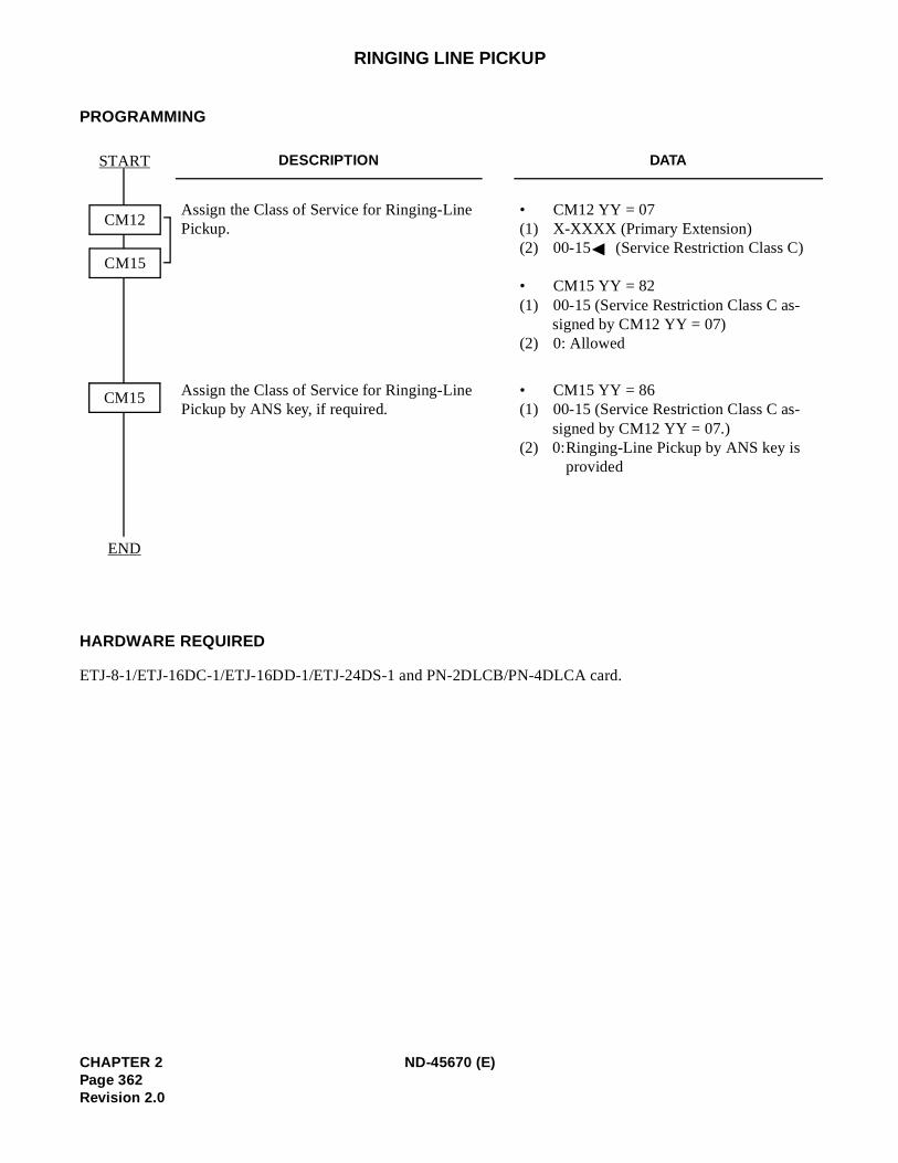
RINGING LINE PICKUP
PROGRAMMING
HARDWARE REQUIRED
ETJ-8-1/ETJ-16DC-1/ETJ-16DD-1/ETJ-24DS-1 and PN-2DLCB/PN-4DLCA card.
DESCRIPTION DATA
Assign the Class of Service for Ringing-Line Pickup.
• CM12 YY = 07 (1) X-XXXX (Primary Extension) (2) 00-15 (Service Restriction Class C)
• CM15 YY = 82 (1) 00-15 (Service Restriction Class C as-
signed by CM12 YY = 07) (2) 0: Allowed
Assign the Class of Service for Ringing-Line Pickup by ANS key, if required.
• CM15 YY = 86 (1) 00-15 (Service Restriction Class C as-
signed by CM12 YY = 07.) (2) 0:Ringing-Line Pickup by ANS key is
provided
START
END
CM12
CM15
CM15
CHAPTER 2 ND-45670 (E)Page 362Revision 2.0
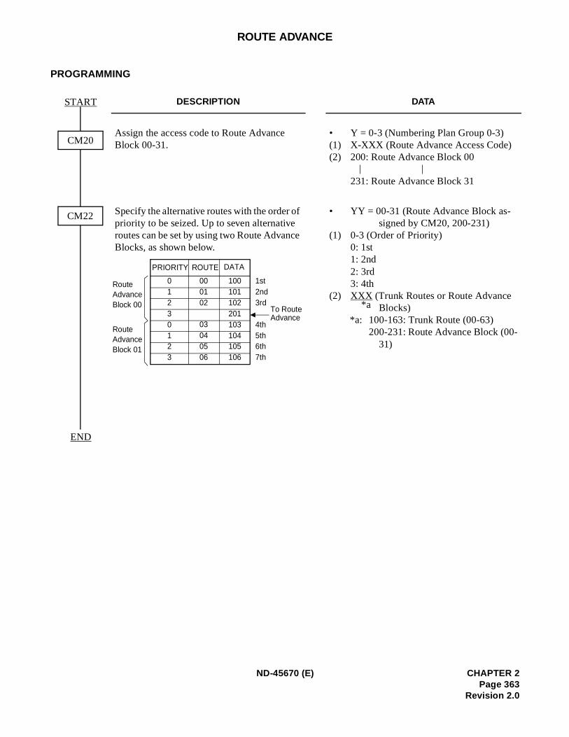
ROUTE ADVANCE
PROGRAMMING
DESCRIPTION DATA
Assign the access code to Route Advance Block 00-31.
• Y = 0-3 (Numbering Plan Group 0-3) (1) X-XXX (Route Advance Access Code) (2) 200: Route Advance Block 00
231: Route Advance Block 31
Specify the alternative routes with the order of priority to be seized. Up to seven alternative routes can be set by using two Route Advance Blocks, as shown below.
• YY = 00-31 (Route Advance Block as-signed by CM20, 200-231)
(1) 0-3 (Order of Priority) 0: 1st 1: 2nd 2: 3rd 3: 4th
(2) XXX (Trunk Routes or Route Advance Blocks)
*a: 100-163: Trunk Route (00-63) 200-231: Route Advance Block (00-
31)
START
END
CM20
CM22
| |
01230123
000102
03040506
100101102201103104105106
PRIORITY ROUTE DATA
1st2nd3rd 4th5th6th7th
RouteAdvanceBlock 00
RouteAdvanceBlock 01
To Route Advance
*a
ND-45670 (E) CHAPTER 2Page 363
Revision 2.0
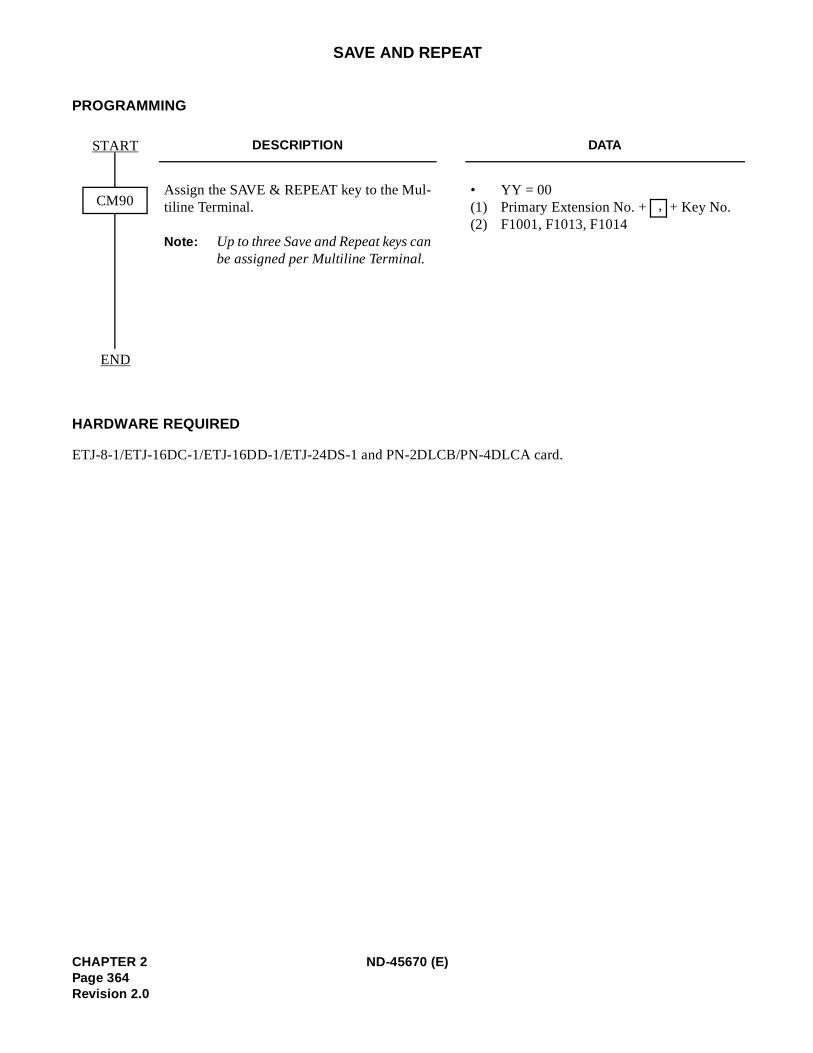
SAVE AND REPEAT
PROGRAMMING
HARDWARE REQUIRED
ETJ-8-1/ETJ-16DC-1/ETJ-16DD-1/ETJ-24DS-1 and PN-2DLCB/PN-4DLCA card.
DESCRIPTION DATA
Assign the SAVE & REPEAT key to the Mul-tiline Terminal.
Note: Up to three Save and Repeat keys canbe assigned per Multiline Terminal.
• YY = 00(1) Primary Extension No. + + Key No. (2) F1001, F1013, F1014
START
END
CM90 ,
CHAPTER 2 ND-45670 (E)Page 364Revision 2.0
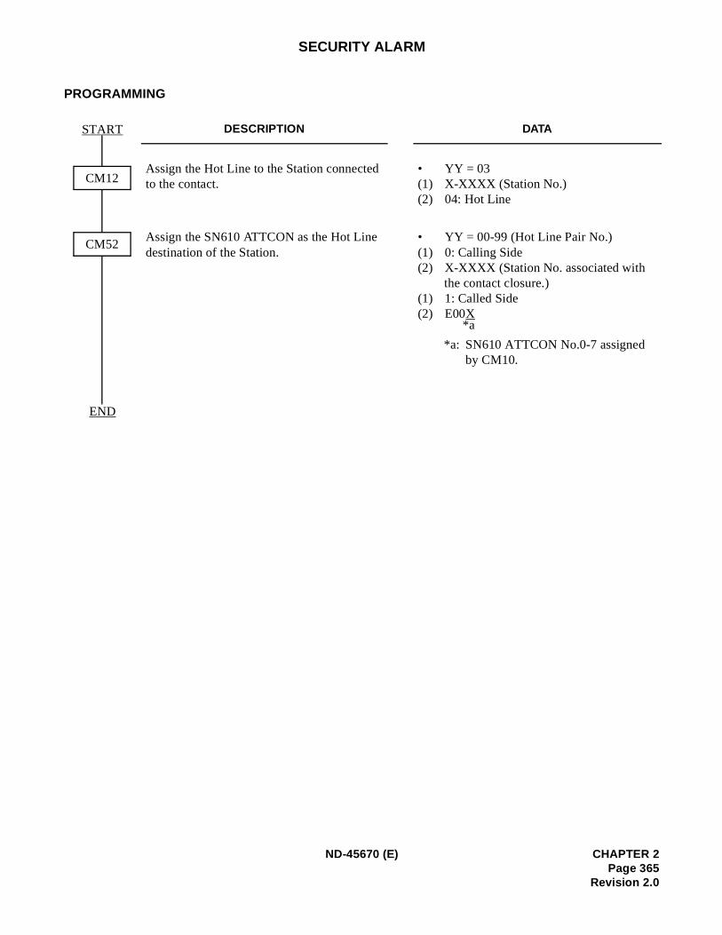
SECURITY ALARM
PROGRAMMING
DESCRIPTION DATA
Assign the Hot Line to the Station connected to the contact.
• YY = 03(1) X-XXXX (Station No.) (2) 04: Hot Line
Assign the SN610 ATTCON as the Hot Line destination of the Station.
• YY = 00-99 (Hot Line Pair No.) (1) 0: Calling Side (2) X-XXXX (Station No. associated with
the contact closure.) (1) 1: Called Side (2) E00X
*a: SN610 ATTCON No.0-7 assigned by CM10.
START
END
CM12
CM52
*a
ND-45670 (E) CHAPTER 2Page 365
Revision 2.0
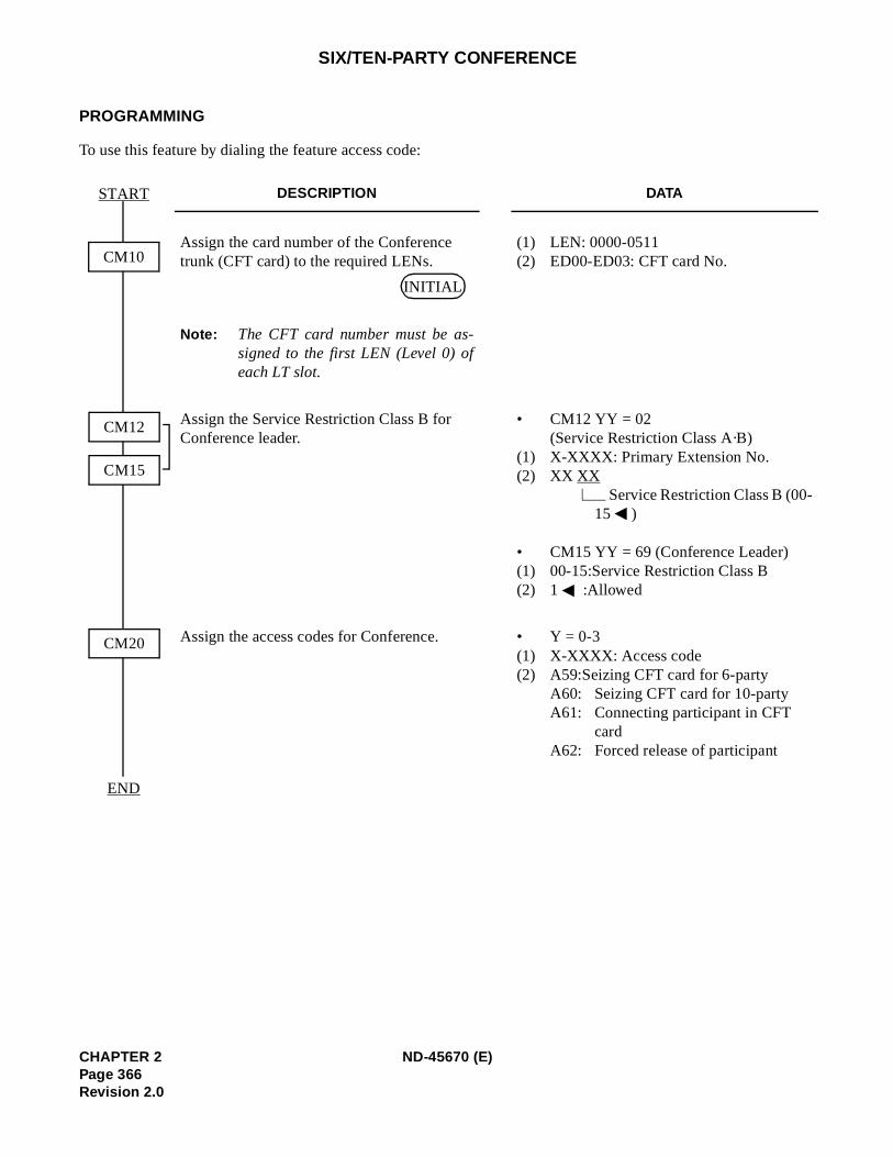
SIX/TEN-PARTY CONFERENCE
PROGRAMMING
To use this feature by dialing the feature access code:
DESCRIPTION DATA
Assign the card number of the Conference trunk (CFT card) to the required LENs.
Note: The CFT card number must be as-signed to the first LEN (Level 0) ofeach LT slot.
(1) LEN: 0000-0511(2) ED00-ED03: CFT card No.
Assign the Service Restriction Class B for Conference leader.
• CM12 YY = 02 (Service Restriction Class A·B)
(1) X-XXXX: Primary Extension No.(2) XX XX
Service Restriction Class B (00-15 )
• CM15 YY = 69 (Conference Leader)(1) 00-15:Service Restriction Class B(2) 1 :Allowed
Assign the access codes for Conference. • Y = 0-3(1) X-XXXX: Access code (2) A59:Seizing CFT card for 6-party
A60: Seizing CFT card for 10-party A61: Connecting participant in CFT
cardA62: Forced release of participant
START
END
CM12
CM15
CM10
CM20
INITIAL
CHAPTER 2 ND-45670 (E)Page 366Revision 2.0
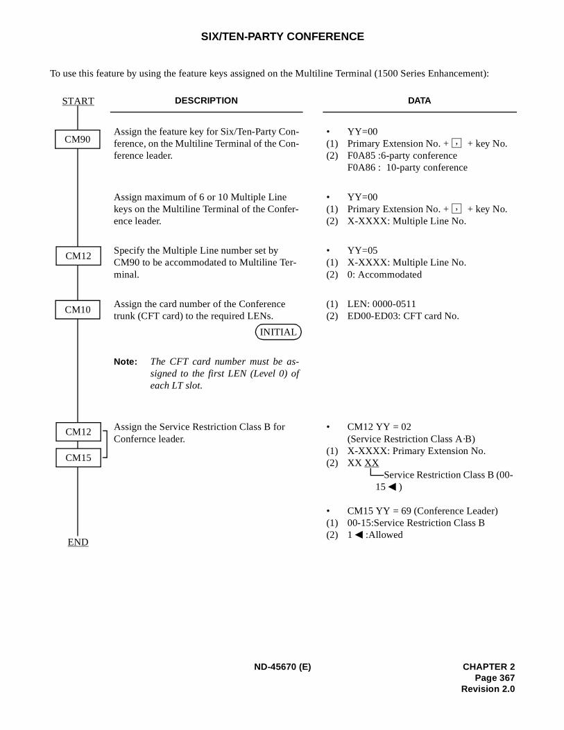
t):
SIX/TEN-PARTY CONFERENCE
To use this feature by using the feature keys assigned on the Multiline Terminal (1500 Series Enhancemen
DESCRIPTION DATA
Assign the feature key for Six/Ten-Party Con-ference, on the Multiline Terminal of the Con-ference leader.
• YY=00(1) Primary Extension No. + + key No. (2) F0A85 :6-party conference
F0A86 : 10-party conference
Assign maximum of 6 or 10 Multiple Line keys on the Multiline Terminal of the Confer-ence leader.
• YY=00(1) Primary Extension No. + + key No. (2) X-XXXX: Multiple Line No.
Specify the Multiple Line number set by CM90 to be accommodated to Multiline Ter-minal.
• YY=05(1) X-XXXX: Multiple Line No.(2) 0: Accommodated
Assign the card number of the Conference trunk (CFT card) to the required LENs.
Note: The CFT card number must be as-signed to the first LEN (Level 0) ofeach LT slot.
(1) LEN: 0000-0511(2) ED00-ED03: CFT card No.
Assign the Service Restriction Class B for Confernce leader.
• CM12 YY = 02 (Service Restriction Class A·B)
(1) X-XXXX: Primary Extension No.(2) XX XX
Service Restriction Class B (00-15 )
• CM15 YY = 69 (Conference Leader)(1) 00-15:Service Restriction Class B(2) 1 :Allowed
START
END
CM12
CM10
CM90
CM12
CM15
,
,
INITIAL
ND-45670 (E) CHAPTER 2Page 367
Revision 2.0
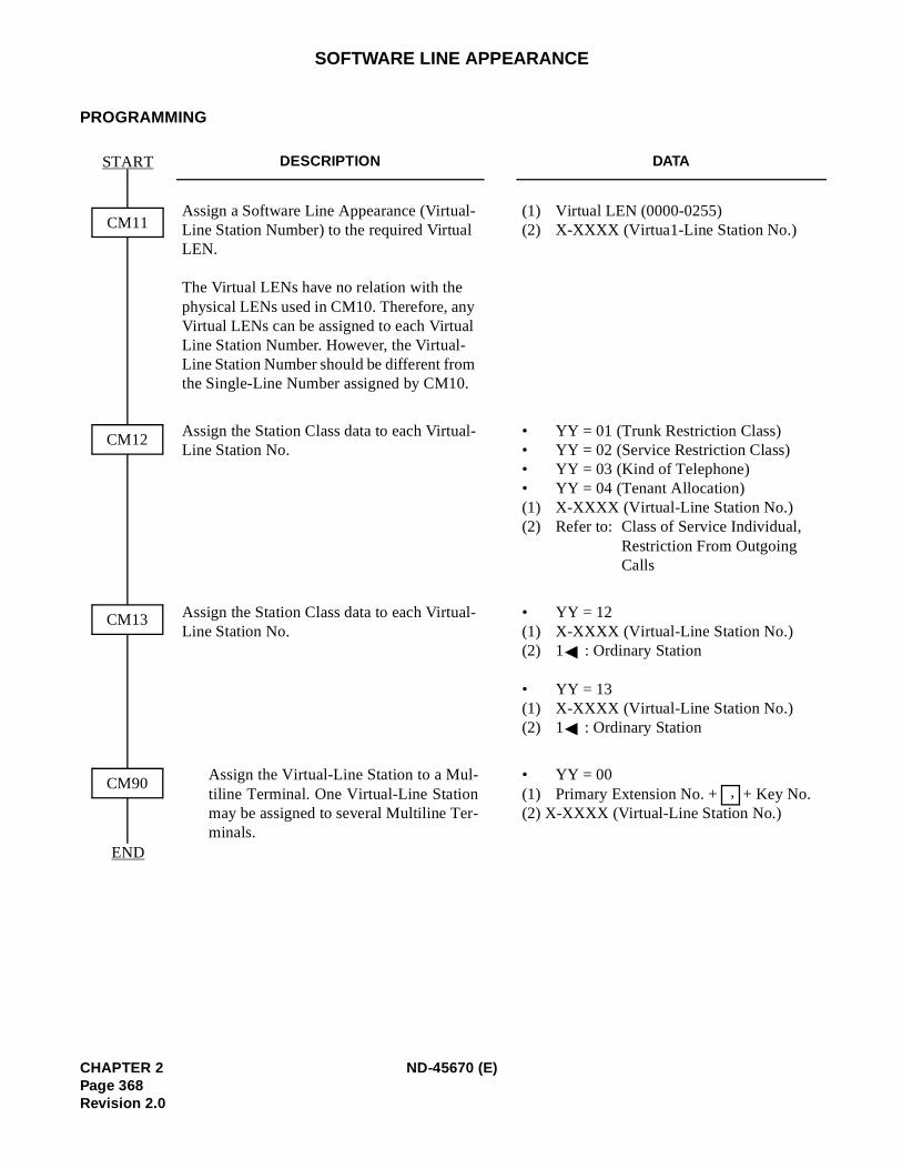
SOFTWARE LINE APPEARANCE
PROGRAMMING
DESCRIPTION DATA
Assign a Software Line Appearance (Virtual-Line Station Number) to the required Virtual LEN.
The Virtual LENs have no relation with the physical LENs used in CM10. Therefore, any Virtual LENs can be assigned to each Virtual Line Station Number. However, the Virtual-Line Station Number should be different from the Single-Line Number assigned by CM10.
(1) Virtual LEN (0000-0255) (2) X-XXXX (Virtua1-Line Station No.)
Assign the Station Class data to each Virtual-Line Station No.
• YY = 01 (Trunk Restriction Class) • YY = 02 (Service Restriction Class) • YY = 03 (Kind of Telephone) • YY = 04 (Tenant Allocation) (1) X-XXXX (Virtual-Line Station No.) (2) Refer to: Class of Service Individual,
Restriction From Outgoing Calls
Assign the Station Class data to each Virtual-Line Station No.
• YY = 12(1) X-XXXX (Virtual-Line Station No.) (2) 1 : Ordinary Station
• YY = 13(1) X-XXXX (Virtual-Line Station No.) (2) 1 : Ordinary Station
Assign the Virtual-Line Station to a Mul-tiline Terminal. One Virtual-Line Stationmay be assigned to several Multiline Ter-minals.
• YY = 00(1) Primary Extension No. + + Key No. (2) X-XXXX (Virtual-Line Station No.)
START
END
CM11
CM12
CM13
CM90 ,
CHAPTER 2 ND-45670 (E)Page 368Revision 2.0
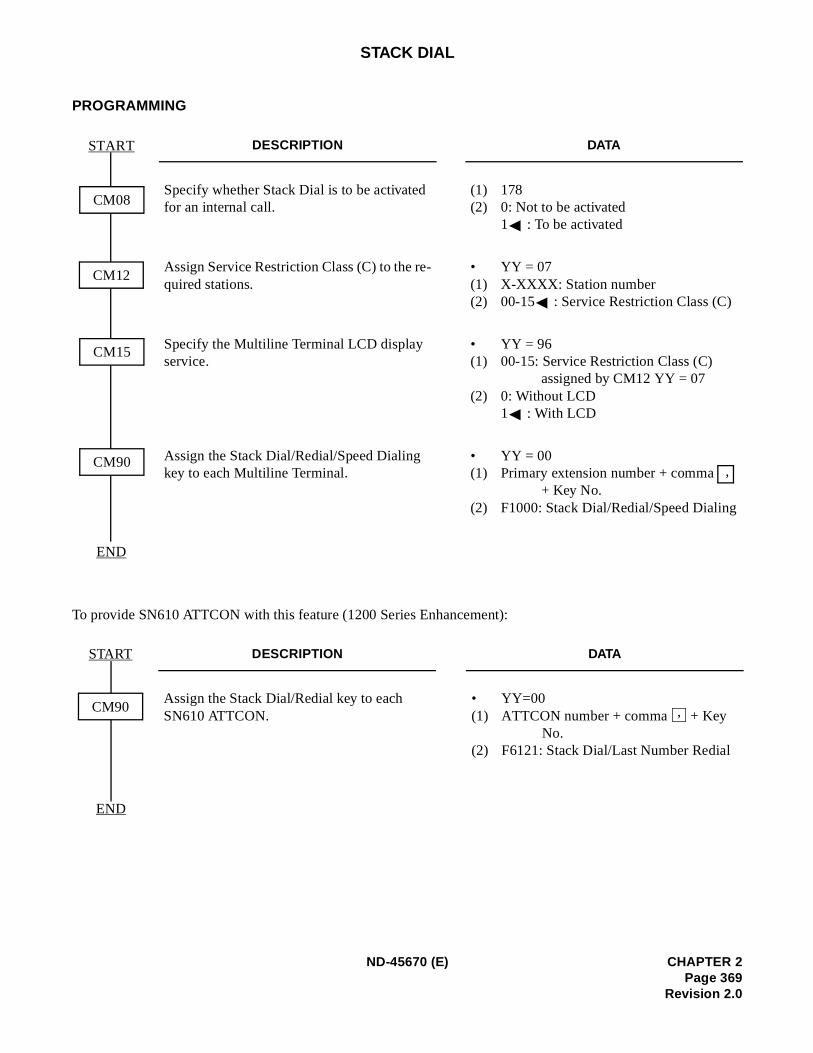
STACK DIAL
PROGRAMMING
To provide SN610 ATTCON with this feature (1200 Series Enhancement):
DESCRIPTION DATA
Specify whether Stack Dial is to be activated for an internal call.
(1) 178(2) 0: Not to be activated
1 : To be activated
Assign Service Restriction Class (C) to the re-quired stations.
• YY = 07(1) X-XXXX: Station number(2) 00-15 : Service Restriction Class (C)
Specify the Multiline Terminal LCD display service.
• YY = 96(1) 00-15: Service Restriction Class (C)
assigned by CM12 YY = 07(2) 0: Without LCD
1 : With LCD
Assign the Stack Dial/Redial/Speed Dialing key to each Multiline Terminal.
• YY = 00(1) Primary extension number + comma
+ Key No.(2) F1000: Stack Dial/Redial/Speed Dialing
DESCRIPTION DATA
Assign the Stack Dial/Redial key to each SN610 ATTCON.
• YY=00(1) ATTCON number + comma + Key
No.(2) F6121: Stack Dial/Last Number Redial
CM15
START
END
CM08
CM12
CM90,
START
END
CM90 ,
ND-45670 (E) CHAPTER 2Page 369
Revision 2.0
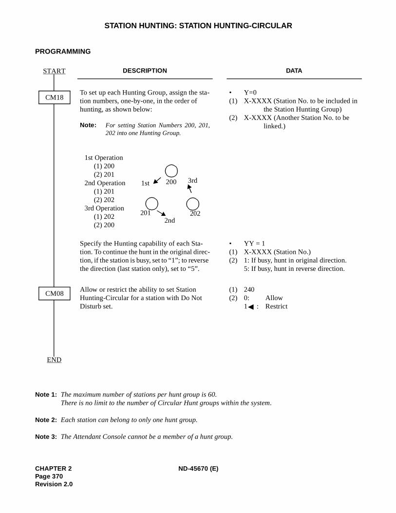
STATION HUNTING: STATION HUNTING-CIRCULAR
PROGRAMMING
Note 1: The maximum number of stations per hunt group is 60.There is no limit to the number of Circular Hunt groups within the system.
Note 2: Each station can belong to only one hunt group.
Note 3: The Attendant Console cannot be a member of a hunt group.
DESCRIPTION DATA
To set up each Hunting Group, assign the sta-tion numbers, one-by-one, in the order of hunting, as shown below:
Note: For setting Station Numbers 200, 201,202 into one Hunting Group.
• Y=0(1) X-XXXX (Station No. to be included in
the Station Hunting Group)(2) X-XXXX (Another Station No. to be
linked.)
Specify the Hunting capability of each Sta-tion. To continue the hunt in the original direc-tion, if the station is busy, set to “1”; to reverse the direction (last station only), set to “5”.
• YY = 1(1) X-XXXX (Station No.)(2) 1: If busy, hunt in original direction.
5: If busy, hunt in reverse direction.
Allow or restrict the ability to set Station Hunting-Circular for a station with Do Not Disturb set.
(1) 240(2) 0: Allow
1 : Restrict
START
END
CM18
CM08
1st Operation(1) 200(2) 201
2nd Operation(1) 201(2) 202
3rd Operation(1) 202(2) 200
200 3rd1st
2022nd
201
CHAPTER 2 ND-45670 (E)Page 370Revision 2.0
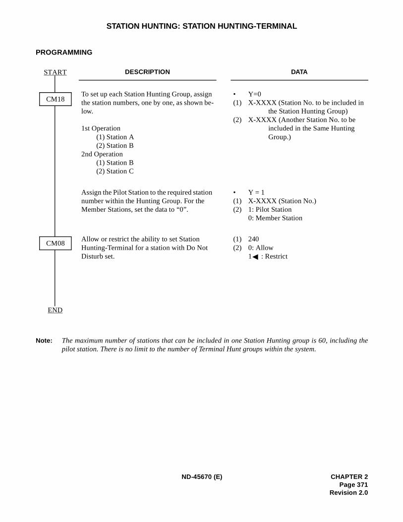
ing the
STATION HUNTING: STATION HUNTING-TERMINAL
PROGRAMMING
Note: The maximum number of stations that can be included in one Station Hunting group is 60, includpilot station. There is no limit to the number of Terminal Hunt groups within the system.
DESCRIPTION DATA
To set up each Station Hunting Group, assign the station numbers, one by one, as shown be-low.
1st Operation(1) Station A(2) Station B
2nd Operation(1) Station B(2) Station C
• Y=0(1) X-XXXX (Station No. to be included in
the Station Hunting Group)(2) X-XXXX (Another Station No. to be
included in the Same Hunting Group.)
Assign the Pilot Station to the required station number within the Hunting Group. For the Member Stations, set the data to “0”.
• Y = 1(1) X-XXXX (Station No.)(2) 1: Pilot Station
0: Member Station
Allow or restrict the ability to set Station Hunting-Terminal for a station with Do Not Disturb set.
(1) 240(2) 0: Allow
1 : Restrict
START
END
CM18
CM08
ND-45670 (E) CHAPTER 2Page 371
Revision 2.0
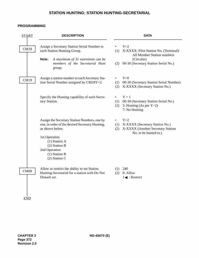
)
STATION HUNTING: STATION HUNTING-SECRETARIAL
PROGRAMMING
DESCRIPTION DATA
Assign a Secretary Station Serial Number to each Station Hunting Group.
Note: A maximum of 31 extensions can bemembers of the Secretarial Huntgroup.
• Y=2(1) X-XXXX: Pilot Station No. (Terminal)/
All Member Station numbers (Circular)
(2) 00-30 (Secretary Station Serial No.)
Assign a station number to each Secretary Sta-tion Serial Number assigned by CM18Y=2.
• Y=0(1) 00-30 (Secretary Station Serial Number(2) X-XXXX (Secretary Station No.)
Specify the Hunting capability of each Secre-tary Station.
• Y = 1(1) 00-30 (Secretary Station Serial No.)(2) 5: Hunting (As per Y=2)
7: No Hunting
Assign the Secretary Station Numbers, one by one, in order of the desired Secretary Hunting, as shown below.
1st Operation(1) Station A(2) Station B
2nd Operation(1) Station B(2) Station C
• Y=2(1) X-XXXX (Secretary Station No.)(2) X-XXXX (Another Secretary Station
No. to be hunted to.)
Allow or restrict the ability to set Station Hunting-Secretarial for a station with Do Not Disturb set.
(1) 240(2) 0: Allow
1 : Restrict
START
END
CM18
CM19
CM08
CHAPTER 2 ND-45670 (E)Page 372Revision 2.0

STATION MESSAGE DETAIL RECORDING (SMDR)
PROGRAMMING
Refer to the SMDR System Manual.
HARDWARE REQUIRED
Refer to the SMDR System Manual.
ND-45670 (E) CHAPTER 2Page 373
Revision 2.0
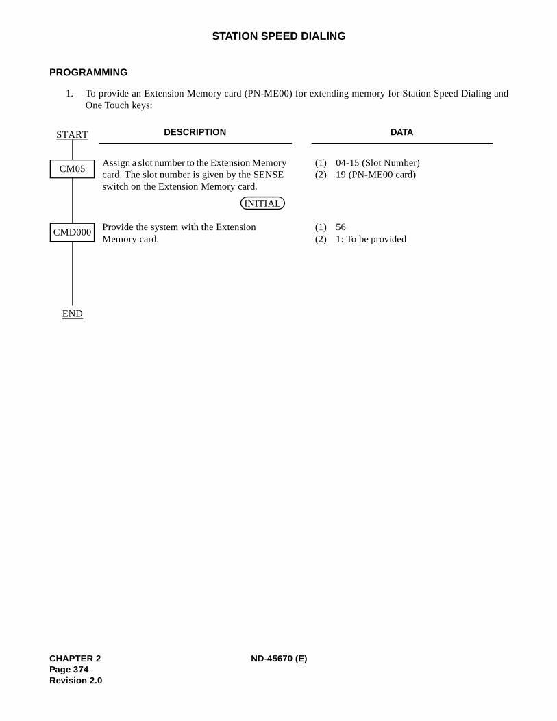
g and
STATION SPEED DIALING
PROGRAMMING
1. To provide an Extension Memory card (PN-ME00) for extending memory for Station Speed DialinOne Touch keys:
DESCRIPTION DATA
Assign a slot number to the Extension Memory card. The slot number is given by the SENSE switch on the Extension Memory card.
(1) 04-15 (Slot Number)(2) 19 (PN-ME00 card)
Provide the system with the Extension Memory card.
(1) 56(2) 1: To be provided
START
CM05
CMD000
END
INITIAL
CHAPTER 2 ND-45670 (E)Page 374Revision 2.0
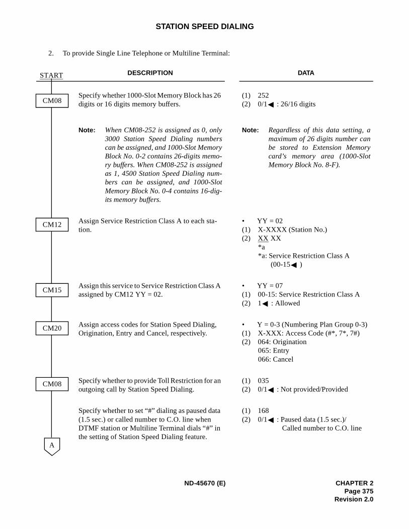
STATION SPEED DIALING
2. To provide Single Line Telephone or Multiline Terminal:
DESCRIPTION DATA
Specify whether 1000-Slot Memory Block has 26 digits or 16 digits memory buffers.
Note: When CM08-252 is assigned as 0, only3000 Station Speed Dialing numberscan be assigned, and 1000-Slot MemoryBlock No. 0-2 contains 26-digits memo-ry buffers. When CM08-252 is assignedas 1, 4500 Station Speed Dialing num-bers can be assigned, and 1000-SlotMemory Block No. 0-4 contains 16-dig-its memory buffers.
(1) 252(2) 0/1 : 26/16 digits
Note: Regardless of this data setting, amaximum of 26 digits number canbe stored to Extension Memorycard’s memory area (1000-SlotMemory Block No. 8-F).
Assign Service Restriction Class A to each sta-tion.
• YY = 02(1) X-XXXX (Station No.)(2) XX XX
*a*a: Service Restriction Class A
(00-15 )
Assign this service to Service Restriction Class A assigned by CM12 YY = 02.
• YY = 07(1) 00-15: Service Restriction Class A(2) 1 : Allowed
Assign access codes for Station Speed Dialing, Origination, Entry and Cancel, respectively.
• Y = 0-3 (Numbering Plan Group 0-3)(1) X-XXX: Access Code (#*, 7*, 7#)(2) 064: Origination
065: Entry 066: Cancel
Specify whether to provide Toll Restriction for an outgoing call by Station Speed Dialing.
(1) 035(2) 0/1 : Not provided/Provided
Specify whether to set “#” dialing as paused data (1.5 sec.) or called number to C.O. line when DTMF station or Multiline Terminal dials “#” in the setting of Station Speed Dialing feature.
(1) 168(2) 0/1 : Paused data (1.5 sec.)/
Called number to C.O. line
START
CM08
CM12
CM15
CM20
CM08
A
ND-45670 (E) CHAPTER 2Page 375
Revision 2.0
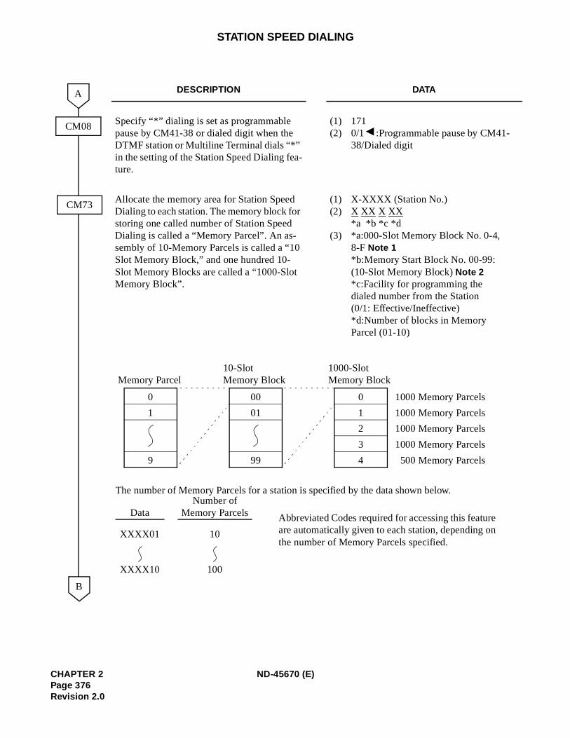
STATION SPEED DIALING
DESCRIPTION DATA
Specify “*” dialing is set as programmable pause by CM41-38 or dialed digit when the DTMF station or Multiline Terminal dials “*” in the setting of the Station Speed Dialing fea-ture.
(1) 171(2) 0/1 :Programmable pause by CM41-
38/Dialed digit
Allocate the memory area for Station Speed Dialing to each station. The memory block for storing one called number of Station Speed Dialing is called a “Memory Parcel”. An as-sembly of 10-Memory Parcels is called a “10 Slot Memory Block,” and one hundred 10-Slot Memory Blocks are called a “1000-Slot Memory Block”.
(1) X-XXXX (Station No.)(2) X XX X XX
*a *b *c *d (3) *a:000-Slot Memory Block No. 0-4,
8-F Note 1 *b:Memory Start Block No. 00-99: (10-Slot Memory Block) Note 2 *c:Facility for programming the dialed number from the Station(0/1: Effective/Ineffective) *d:Number of blocks in Memory Parcel (01-10)
CM08
CM73
B
A
The number of Memory Parcels for a station is specified by the data shown below.
DataNumber of
Memory Parcels Abbreviated Codes required for accessing this featureare automatically given to each station, depending onthe number of Memory Parcels specified.
XXXX01 10
XXXX10 100
0
4
1
2
3
1000-SlotMemory Block
0
9
1
Memory Parcel
00
99
01
10-SlotMemory Block
1000 Memory Parcels
1000 Memory Parcels
1000 Memory Parcels
1000 Memory Parcels
500 Memory Parcels
CHAPTER 2 ND-45670 (E)Page 376Revision 2.0
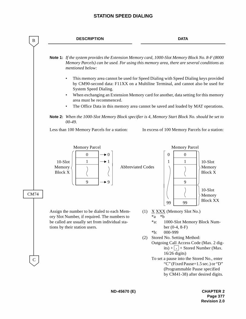
8000ns as
ided for
tions.
set to
n:
-
r
STATION SPEED DIALING
DESCRIPTION DATA
Note 1: If the system provides the Extension Memory card, 1000-Slot Memory Block No. 8-F (Memory Parcels) can be used. For using this memory area, there are several conditiomentioned below:
• This memory area cannot be used for Speed Dialing with Speed Dialing keys provby CM90-second data: F11XX on a Multiline Terminal, and cannot also be usedSystem Speed Dialing.
• When exchanging an Extension Memory card for another, data setting for this memoryarea must be recommenced.
• The Office Data in this memory area cannot be saved and loaded by MAT opera
Note 2: When the 1000-Slot Memory Block specifier is 4, Memory Start Block No. should be 00-49.
Less than 100 Memory Parcels for a station: In excess of 100 Memory Parcels for a statio
Assign the number to be dialed to each Mem-ory Slot Number, if required. The numbers to be called are usually set from individual sta-tions by their station users.
(1) X XXX (Memory Slot No.) *a *b *a: 1000-Slot Memory Block Num-
ber (0-4, 8-F) *b: 000-999
(2) Stored No. Setting Method: Outgoing Call Access Code (Max. 2 dig
its) + + Stored Number (Max. 16/26 digits)
To set a pause into the Stored No., ente“C” (Fixed Pause=1.5 sec.) or “D” (Programmable Pause specified by CM41-38) after desired digits.
B
CM74
C
0
9
1
Memory Parcel
10-SlotMemoryBlock X
Memory Parcel
0
9
1
0
9
1 10-Slot Memory Block X
99
10-Slot Memory Block XX
0
1
99
Abbreviated Codes
,
ND-45670 (E) CHAPTER 2Page 377
Revision 2.0
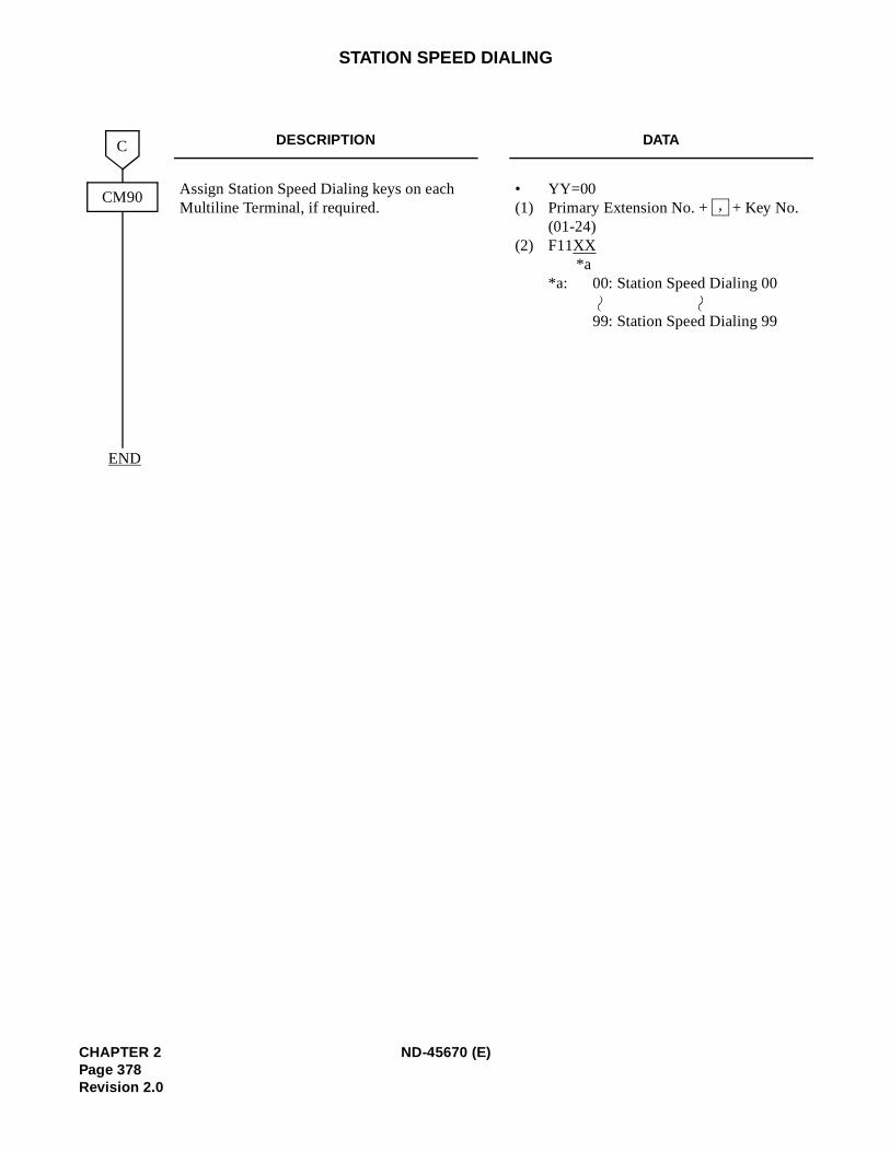
STATION SPEED DIALING
DESCRIPTION DATA
Assign Station Speed Dialing keys on each Multiline Terminal, if required.
• YY=00(1) Primary Extension No. + + Key No.
(01-24)(2) F11XX
*a *a: 00: Station Speed Dialing 00
99: Station Speed Dialing 99
CM90
C
END
,
CHAPTER 2 ND-45670 (E)Page 378Revision 2.0
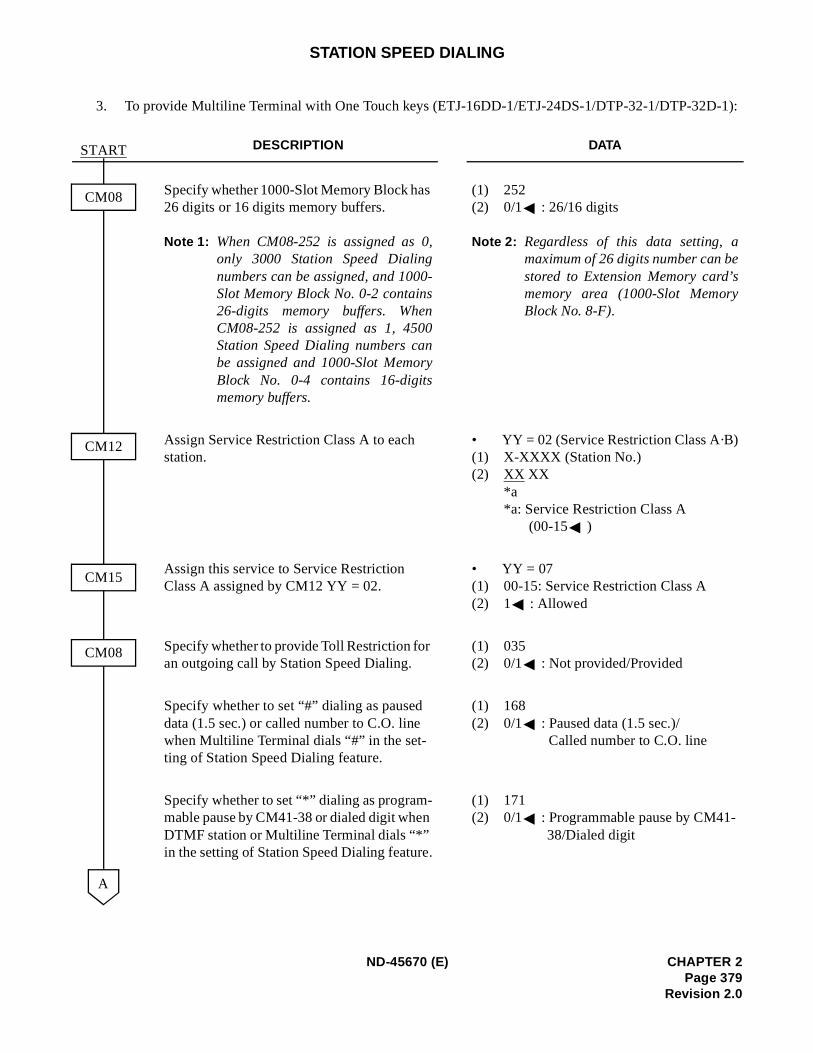
-1):
STATION SPEED DIALING
3. To provide Multiline Terminal with One Touch keys (ETJ-16DD-1/ETJ-24DS-1/DTP-32-1/DTP-32D
DESCRIPTION DATA
Specify whether 1000-Slot Memory Block has 26 digits or 16 digits memory buffers.
Note 1: When CM08-252 is assigned as 0,only 3000 Station Speed Dialingnumbers can be assigned, and 1000-Slot Memory Block No. 0-2 contains26-digits memory buffers. WhenCM08-252 is assigned as 1, 4500Station Speed Dialing numbers canbe assigned and 1000-Slot MemoryBlock No. 0-4 contains 16-digitsmemory buffers.
(1) 252(2) 0/1 : 26/16 digits
Note 2: Regardless of this data setting, amaximum of 26 digits number can bestored to Extension Memory card’smemory area (1000-Slot MemoryBlock No. 8-F).
Assign Service Restriction Class A to each station.
• YY = 02 (Service Restriction Class A·B)(1) X-XXXX (Station No.)(2) XX XX
*a*a: Service Restriction Class A
(00-15 )
Assign this service to Service Restriction Class A assigned by CM12 YY = 02.
• YY = 07(1) 00-15: Service Restriction Class A(2) 1 : Allowed
Specify whether to provide Toll Restriction for an outgoing call by Station Speed Dialing.
(1) 035(2) 0/1 : Not provided/Provided
Specify whether to set “#” dialing as paused data (1.5 sec.) or called number to C.O. line when Multiline Terminal dials “#” in the set-ting of Station Speed Dialing feature.
(1) 168(2) 0/1 : Paused data (1.5 sec.)/
Called number to C.O. line
Specify whether to set “*” dialing as program-mable pause by CM41-38 or dialed digit when DTMF station or Multiline Terminal dials “*” in the setting of Station Speed Dialing feature.
(1) 171(2) 0/1 : Programmable pause by CM41-
38/Dialed digit
START
CM08
A
CM12
CM15
CM08
ND-45670 (E) CHAPTER 2Page 379
Revision 2.0
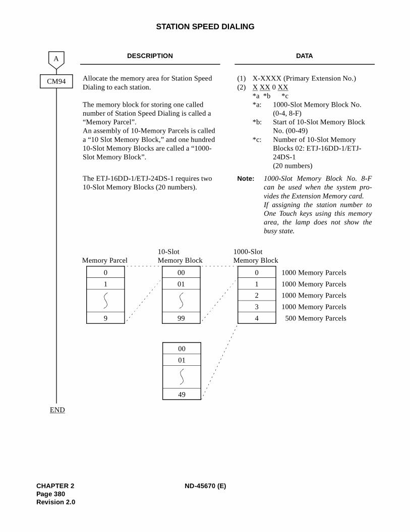
-
y
STATION SPEED DIALING
DESCRIPTION DATA
Allocate the memory area for Station Speed Dialing to each station.
The memory block for storing one called number of Station Speed Dialing is called a “Memory Parcel”. An assembly of 10-Memory Parcels is called a “10 Slot Memory Block,” and one hundred 10-Slot Memory Blocks are called a “1000-Slot Memory Block”.
(1) X-XXXX (Primary Extension No.)(2) X XX 0 XX
*a *b *c *a: 1000-Slot Memory Block No.
(0-4, 8-F) *b: Start of 10-Slot Memory Block
No. (00-49) *c: Number of 10-Slot Memory
Blocks 02: ETJ-16DD-1/ETJ-24DS-1 (20 numbers)
The ETJ-16DD-1/ETJ-24DS-1 requires two 10-Slot Memory Blocks (20 numbers).
Note: 1000-Slot Memory Block No. 8-Fcan be used when the system provides the Extension Memory card.If assigning the station number toOne Touch keys using this memorarea, the lamp does not show thebusy state.
CM94
A
END
0
4
1
2
3
1000-SlotMemory Block
0
9
1
Memory Parcel
00
99
01
10-SlotMemory Block
1000 Memory Parcels
1000 Memory Parcels
1000 Memory Parcels
1000 Memory Parcels
500 Memory Parcels
00
49
01
CHAPTER 2 ND-45670 (E)Page 380Revision 2.0
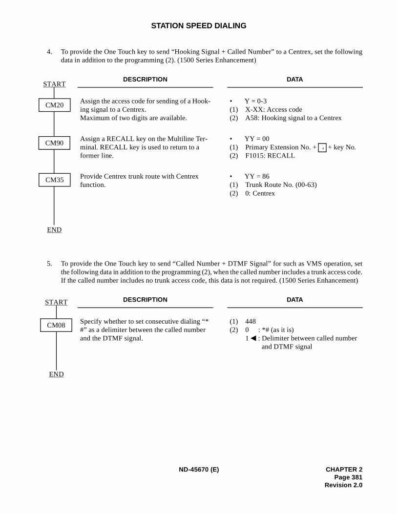
owing
n, sets code.ement)
STATION SPEED DIALING
4. To provide the One Touch key to send “Hooking Signal + Called Number” to a Centrex, set the folldata in addition to the programming (2). (1500 Series Enhancement)
5. To provide the One Touch key to send “Called Number + DTMF Signal” for such as VMS operatiothe following data in addition to the programming (2), when the called number includes a trunk accesIf the called number includes no trunk access code, this data is not required. (1500 Series Enhanc
DESCRIPTION DATA
Assign the access code for sending of a Hook-ing signal to a Centrex.Maximum of two digits are available.
• Y = 0-3(1) X-XX: Access code(2) A58: Hooking signal to a Centrex
Assign a RECALL key on the Multiline Ter-minal. RECALL key is used to return to a former line.
• YY = 00(1) Primary Extension No. + + key No.(2) F1015: RECALL
Provide Centrex trunk route with Centrex function.
• YY = 86(1) Trunk Route No. (00-63)(2) 0: Centrex
DESCRIPTION DATA
Specify whether to set consecutive dialing “* #” as a delimiter between the called number and the DTMF signal.
(1) 448(2) 0 : *# (as it is)
1 : Delimiter between called number and DTMF signal
CM35
START
END
CM20
CM90 ,
START
END
CM08
ND-45670 (E) CHAPTER 2Page 381
Revision 2.0
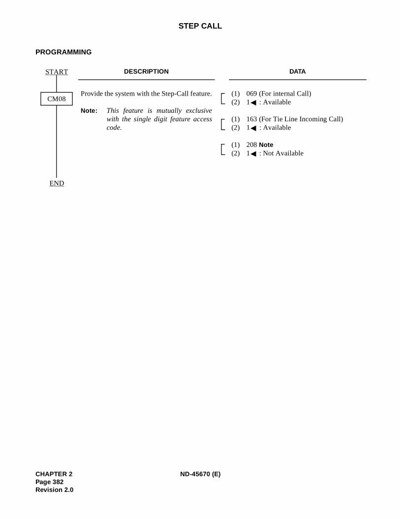
STEP CALL
PROGRAMMING
DESCRIPTION DATA
Provide the system with the Step-Call feature.
Note: This feature is mutually exclusivewith the single digit feature accesscode.
(1) 069 (For internal Call) (2) 1 : Available
(1) 163 (For Tie Line Incoming Call) (2) 1 : Available
(1) 208 Note (2) 1 : Not Available
START
END
CM08
CHAPTER 2 ND-45670 (E)Page 382Revision 2.0
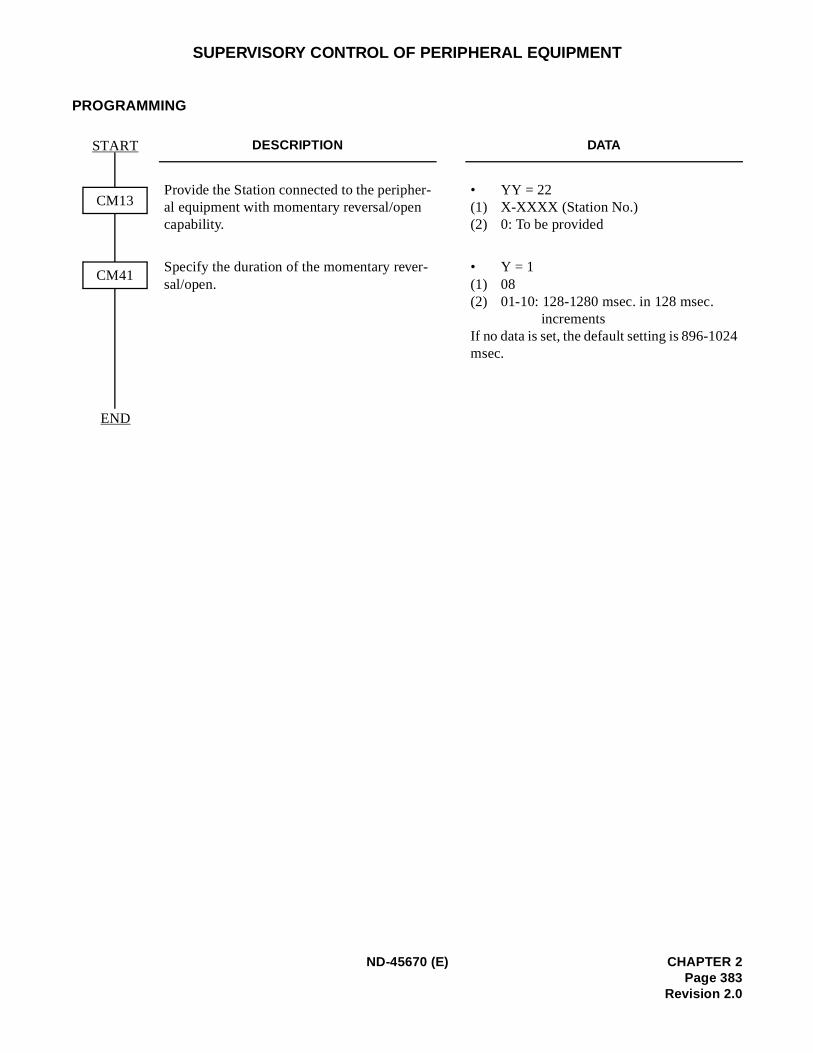
4
SUPERVISORY CONTROL OF PERIPHERAL EQUIPMENT
PROGRAMMING
DESCRIPTION DATA
Provide the Station connected to the peripher-al equipment with momentary reversal/open capability.
• YY = 22(1) X-XXXX (Station No.) (2) 0: To be provided
Specify the duration of the momentary rever-sal/open.
• Y = 1 (1) 08(2) 01-10: 128-1280 msec. in 128 msec.
incrementsIf no data is set, the default setting is 896-102msec.
START
END
CM13
CM41
ND-45670 (E) CHAPTER 2Page 383
Revision 2.0
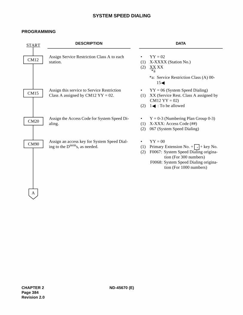
SYSTEM SPEED DIALING
PROGRAMMING
DESCRIPTION DATA
Assign Service Restriction Class A to each station.
• YY = 02(1) X-XXXX (Station No.) (2) XX XX
*a: Service Restriction Class (A) 00-15
Assign this service to Service Restriction Class A assigned by CM12 YY = 02.
• YY = 06 (System Speed Dialing) (1) XX (Service Rest. Class A assigned by
CM12 YY = 02) (2) 1 : To be allowed
Assign the Access Code for System Speed Di-aling.
• Y = 0-3 (Numbering Plan Group 0-3) (1) X-XXX: Access Code (##) (2) 067 (System Speed Dialing)
Assign an access key for System Speed Dial-ing to the Dterms, as needed.
• YY = 00(1) Primary Extension No. + + key No. (2) F0067: System Speed Dialing origina-
tion (For 300 numbers) F0068: System Speed Dialing origina-
tion (For 1000 numbers)
START
CM12
CM15
A
CM20
CM90
*a
,
CHAPTER 2 ND-45670 (E)Page 384Revision 2.0
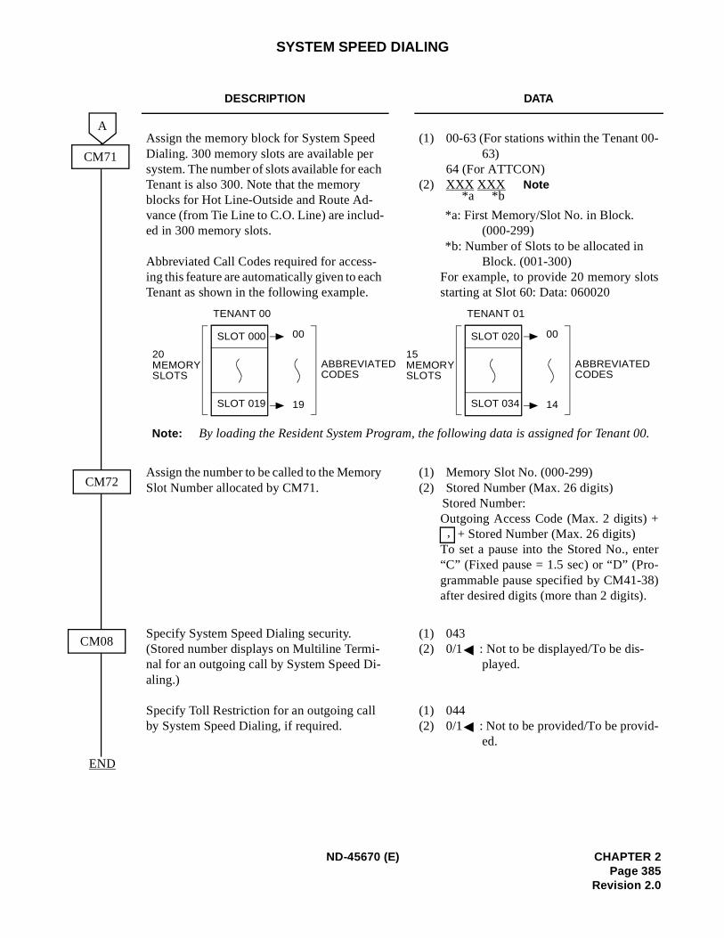
-
s
er
)
00.
SYSTEM SPEED DIALING
DESCRIPTION DATA
Assign the memory block for System Speed Dialing. 300 memory slots are available per system. The number of slots available for each Tenant is also 300. Note that the memory blocks for Hot Line-Outside and Route Ad-vance (from Tie Line to C.O. Line) are includ-ed in 300 memory slots.
Abbreviated Call Codes required for access-ing this feature are automatically given to each Tenant as shown in the following example.
(1) 00-63 (For stations within the Tenant 0063)
64 (For ATTCON) (2) XXX XXX Note
*a: First Memory/Slot No. in Block. (000-299)
*b: Number of Slots to be allocated in Block. (001-300)
For example, to provide 20 memory slotstarting at Slot 60: Data: 060020
Assign the number to be called to the Memory Slot Number allocated by CM71.
(1) Memory Slot No. (000-299) (2) Stored Number (Max. 26 digits)
Stored Number: Outgoing Access Code (Max. 2 digits) +
+ Stored Number (Max. 26 digits) To set a pause into the Stored No., ent“C” (Fixed pause = 1.5 sec) or “D” (Pro-grammable pause specified by CM41-38after desired digits (more than 2 digits).
Specify System Speed Dialing security. (Stored number displays on Multiline Termi-nal for an outgoing call by System Speed Di-aling.)
Specify Toll Restriction for an outgoing call by System Speed Dialing, if required.
(1) 043 (2) 0/1 : Not to be displayed/To be dis-
played.
(1) 044 (2) 0/1 : Not to be provided/To be provid-
ed.
CM71
A
CM72
END
CM08
TENANT 00
SLOT 000
SLOT 019
20MEMORYSLOTS
00
19
ABBREVIATEDCODES
TENANT 01
SLOT 020
SLOT 034
15MEMORYSLOTS
00
14
ABBREVIATEDCODES
Note: By loading the Resident System Program, the following data is assigned for Tenant
*a *b
,
ND-45670 (E) CHAPTER 2Page 385
Revision 2.0
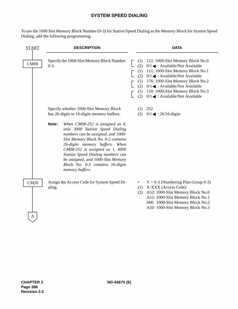
Speed
SYSTEM SPEED DIALING
To use the 1000 Slot Memory Block Number (0-3) for Station Speed Dialing as the Memory Block for SystemDialing, add the following programming.
DESCRIPTION DATA
Specify the 1000-Slot Memory Block Number 0-3.
(1) 112: 1000-Slot Memory Block No.0 (2) 0/1 : Available/Not Available(1) 111: 1000-Slot Memory Block No.1 (2) 0/1 : Available/Not Available(1) 176: 1000-Slot Memory Block No.2 (2) 0/1 : Available/Not Available(1) 110: 1000-Slot Memory Block No.3 (2) 0/1 : Available/Not Available
Specify whether 1000-Slot Memory Block has 26-digits or 16-digits memory buffers.
Note: When CM08-252 is assigned as 0,only 3000 Station Speed Dialingnumbers can be assigned, and 1000-Slot Memory Block No. 0-2 contains26-digits memory buffers. WhenCM08-252 is assigned as 1, 4000Station Speed Dialing numbers canbe assigned, and 1000-Slot MemoryBlock No. 0-3 contains 16-digitsmemory buffers.
(1) 252 (2) 0/1 : 26/16-digits
Assign the Access Code for System Speed Di-aling.
• Y = 0-3 (Numbering Plan Group 0-3) (1) X-XXX (Access Code) (2) A52: 1000-Slot Memory Block No.0
A51: 1000-Slot Memory Block No.1068: 1000-Slot Memory Block No.2A50: 1000-Slot Memory Block No.3
START
CM08
A
CM20
CHAPTER 2 ND-45670 (E)Page 386Revision 2.0
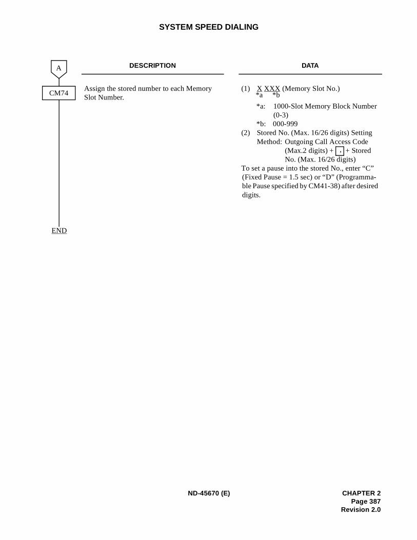
d
SYSTEM SPEED DIALING
DESCRIPTION DATA
Assign the stored number to each Memory Slot Number.
(1) X XXX (Memory Slot No.)
*a: 1000-Slot Memory Block Number (0-3)
*b: 000-999 (2) Stored No. (Max. 16/26 digits) Setting
Method: Outgoing Call Access Code (Max.2 digits) + + Stored No. (Max. 16/26 digits)
To set a pause into the stored No., enter “C”(Fixed Pause = 1.5 sec) or “D” (Programma-ble Pause specified by CM41-38) after desiredigits.
CM74
A
END
*a *b
,
ND-45670 (E) CHAPTER 2Page 387
Revision 2.0
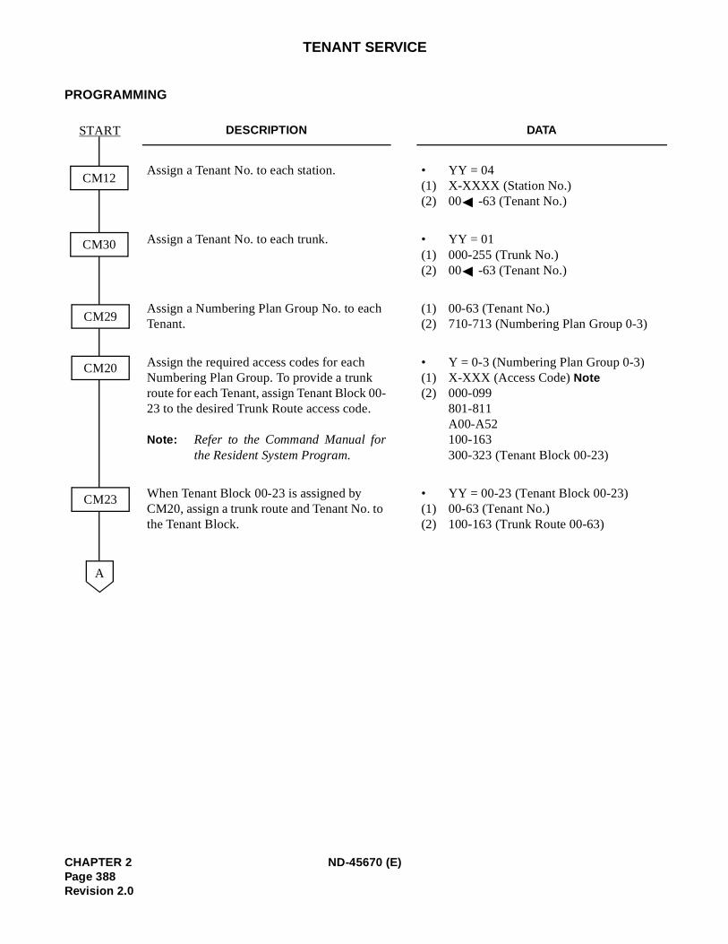
TENANT SERVICE
PROGRAMMING
DESCRIPTION DATA
Assign a Tenant No. to each station. • YY = 04(1) X-XXXX (Station No.) (2) 00 -63 (Tenant No.)
Assign a Tenant No. to each trunk. • YY = 01(1) 000-255 (Trunk No.) (2) 00 -63 (Tenant No.)
Assign a Numbering Plan Group No. to each Tenant.
(1) 00-63 (Tenant No.) (2) 710-713 (Numbering Plan Group 0-3)
Assign the required access codes for each Numbering Plan Group. To provide a trunk route for each Tenant, assign Tenant Block 00-23 to the desired Trunk Route access code.
Note: Refer to the Command Manual forthe Resident System Program.
• Y = 0-3 (Numbering Plan Group 0-3) (1) X-XXX (Access Code) Note(2) 000-099
801-811 A00-A52 100-163 300-323 (Tenant Block 00-23)
When Tenant Block 00-23 is assigned by CM20, assign a trunk route and Tenant No. to the Tenant Block.
• YY = 00-23 (Tenant Block 00-23) (1) 00-63 (Tenant No.) (2) 100-163 (Trunk Route 00-63)
START
CM12
CM30
A
CM29
CM20
CM23
CHAPTER 2 ND-45670 (E)Page 388Revision 2.0
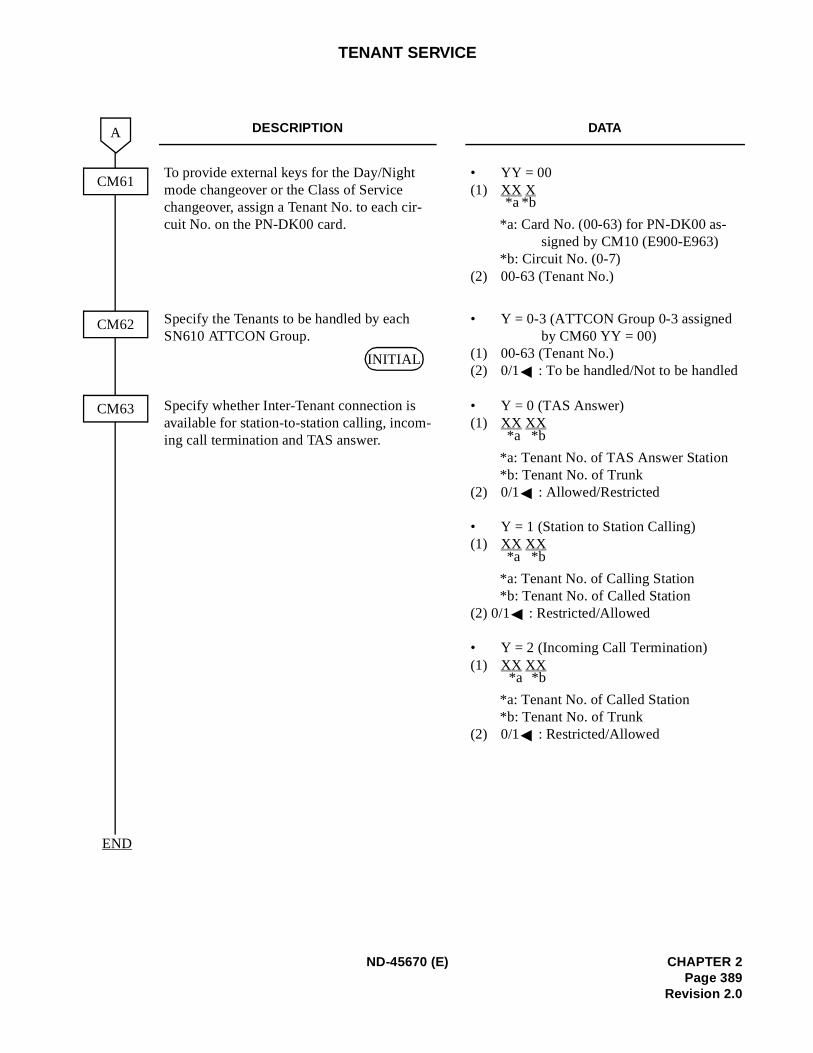
TENANT SERVICE
DESCRIPTION DATA
To provide external keys for the Day/Night mode changeover or the Class of Service changeover, assign a Tenant No. to each cir-cuit No. on the PN-DK00 card.
• YY = 00 (1) XX X
*a: Card No. (00-63) for PN-DK00 as-signed by CM10 (E900-E963)
*b: Circuit No. (0-7) (2) 00-63 (Tenant No.)
Specify the Tenants to be handled by each SN610 ATTCON Group.
• Y = 0-3 (ATTCON Group 0-3 assigned by CM60 YY = 00)
(1) 00-63 (Tenant No.) (2) 0/1 : To be handled/Not to be handled
Specify whether Inter-Tenant connection is available for station-to-station calling, incom-ing call termination and TAS answer.
• Y = 0 (TAS Answer) (1) XX XX
*a: Tenant No. of TAS Answer Station *b: Tenant No. of Trunk
(2) 0/1 : Allowed/Restricted
• Y = 1 (Station to Station Calling) (1) XX XX
*a: Tenant No. of Calling Station *b: Tenant No. of Called Station
(2) 0/1 : Restricted/Allowed
• Y = 2 (Incoming Call Termination) (1) XX XX
*a: Tenant No. of Called Station*b: Tenant No. of Trunk
(2) 0/1 : Restricted/Allowed
CM61
A
CM63
END
CM62
*a *b
INITIAL
*a *b
*a *b
*a *b
ND-45670 (E) CHAPTER 2Page 389
Revision 2.0
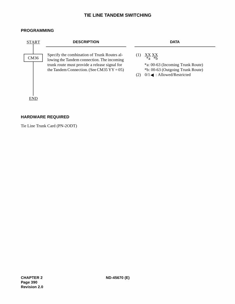
TIE LINE TANDEM SWITCHING
PROGRAMMING
HARDWARE REQUIRED
Tie Line Trunk Card (PN-2ODT)
DESCRIPTION DATA
Specify the combination of Trunk Routes al-lowing the Tandem connection. The incoming trunk route must provide a release signal for the Tandem Connection. (See CM35 YY = 05)
(1) XX XX
*a: 00-63 (Incoming Trunk Route) *b: 00-63 (Outgoing Trunk Route)
(2) 0/1 : Allowed/Restricted
START
END
CM36 *a *b
CHAPTER 2 ND-45670 (E)Page 390Revision 2.0
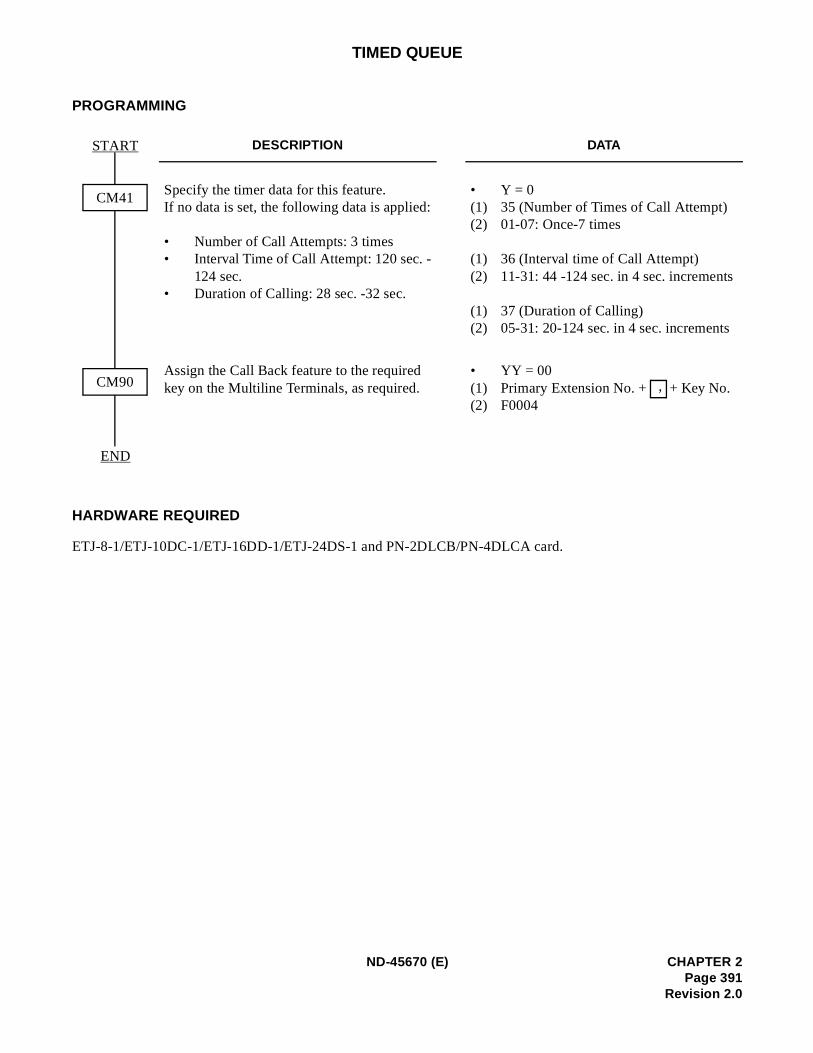
TIMED QUEUE
PROGRAMMING
HARDWARE REQUIRED
ETJ-8-1/ETJ-10DC-1/ETJ-16DD-1/ETJ-24DS-1 and PN-2DLCB/PN-4DLCA card.
DESCRIPTION DATA
Specify the timer data for this feature.If no data is set, the following data is applied:
• Number of Call Attempts: 3 times• Interval Time of Call Attempt: 120 sec. -
124 sec.• Duration of Calling: 28 sec. -32 sec.
• Y = 0(1) 35 (Number of Times of Call Attempt)(2) 01-07: Once-7 times (1) 36 (Interval time of Call Attempt)(2) 11-31: 44 -124 sec. in 4 sec. increments (1) 37 (Duration of Calling)(2) 05-31: 20-124 sec. in 4 sec. increments
Assign the Call Back feature to the required key on the Multiline Terminals, as required.
• YY = 00(1) Primary Extension No. + + Key No.(2) F0004
START
END
CM41
CM90 ,
ND-45670 (E) CHAPTER 2Page 391
Revision 2.0
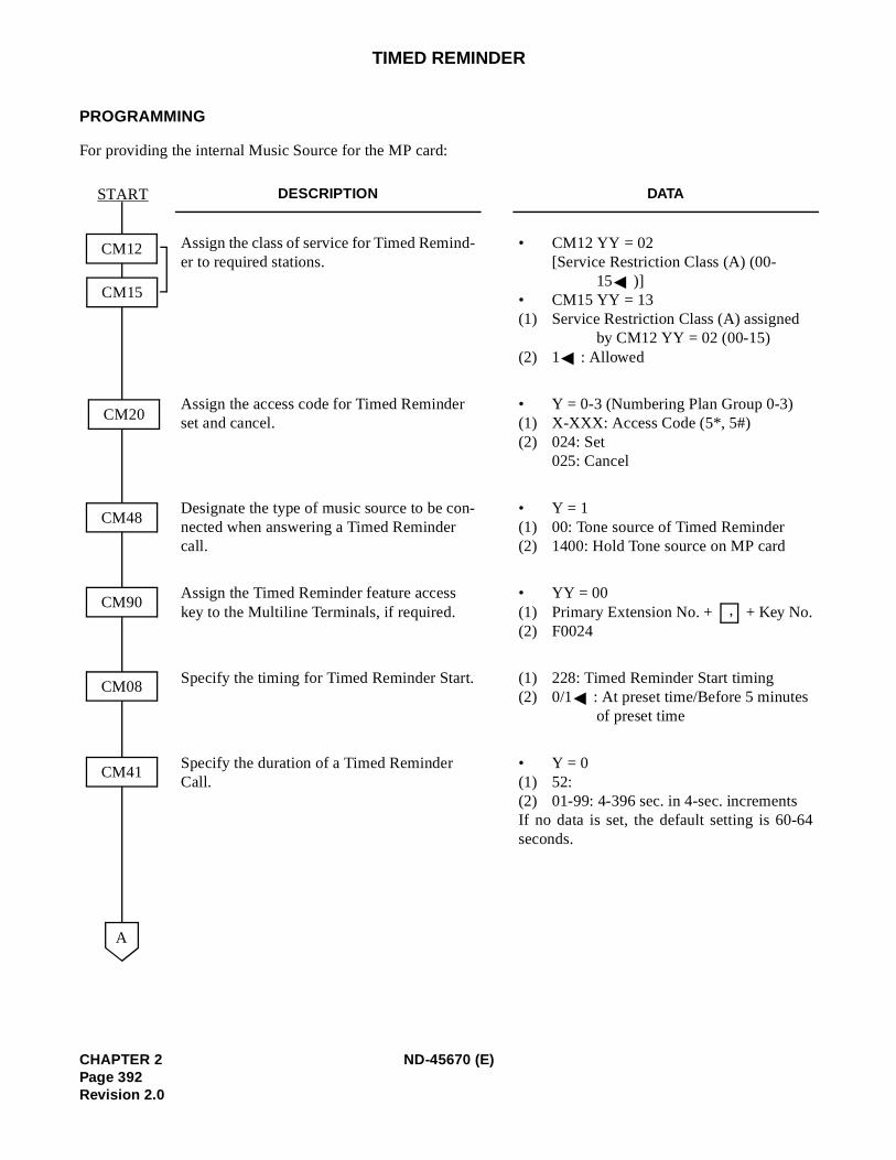
4
TIMED REMINDER
PROGRAMMING
For providing the internal Music Source for the MP card:
DESCRIPTION DATA
Assign the class of service for Timed Remind-er to required stations.
• CM12 YY = 02[Service Restriction Class (A) (00-
15 )] • CM15 YY = 13(1) Service Restriction Class (A) assigned
by CM12 YY = 02 (00-15)(2) 1 : Allowed
Assign the access code for Timed Reminder set and cancel.
• Y = 0-3 (Numbering Plan Group 0-3)(1) X-XXX: Access Code (5*, 5#)(2) 024: Set
025: Cancel
Designate the type of music source to be con-nected when answering a Timed Reminder call.
• Y = 1(1) 00: Tone source of Timed Reminder(2) 1400: Hold Tone source on MP card
Assign the Timed Reminder feature access key to the Multiline Terminals, if required.
• YY = 00(1) Primary Extension No. + + Key No.(2) F0024
Specify the timing for Timed Reminder Start. (1) 228: Timed Reminder Start timing(2) 0/1 : At preset time/Before 5 minutes
of preset time
Specify the duration of a Timed Reminder Call.
• Y = 0(1) 52:(2) 01-99: 4-396 sec. in 4-sec. incrementsIf no data is set, the default setting is 60-6seconds.
CM12
CM20
START
A
CM15
CM48
CM90
CM08
CM41
,
CHAPTER 2 ND-45670 (E)Page 392Revision 2.0
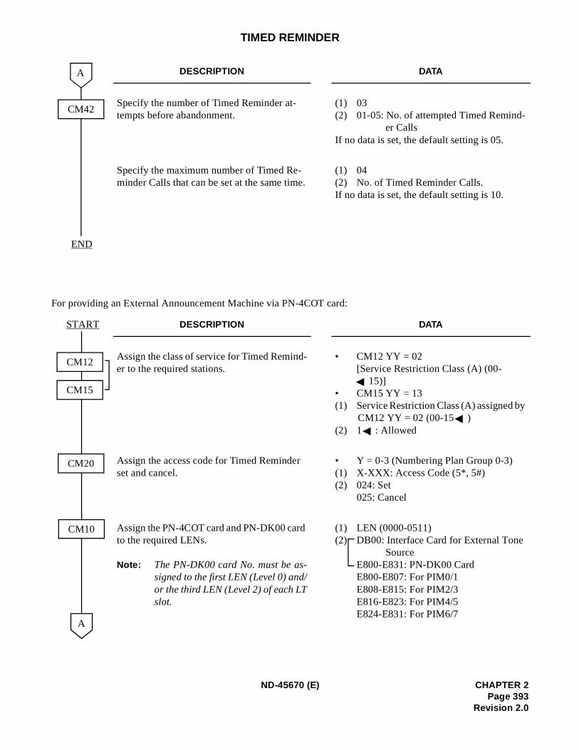
y
TIMED REMINDER
For providing an External Announcement Machine via PN-4COT card:
DESCRIPTION DATA
Specify the number of Timed Reminder at-tempts before abandonment.
(1) 03(2) 01-05: No. of attempted Timed Remind-
er Calls If no data is set, the default setting is 05.
Specify the maximum number of Timed Re-minder Calls that can be set at the same time.
(1) 04(2) No. of Timed Reminder Calls. If no data is set, the default setting is 10.
DESCRIPTION DATA
Assign the class of service for Timed Remind-er to the required stations.
• CM12 YY = 02 [Service Restriction Class (A) (00-
15)]• CM15 YY = 13 (1) Service Restriction Class (A) assigned b
CM12 YY = 02 (00-15 ) (2) 1 : Allowed
Assign the access code for Timed Reminder set and cancel.
• Y = 0-3 (Numbering Plan Group 0-3)(1) X-XXX: Access Code (5*, 5#) (2) 024: Set
025: Cancel
Assign the PN-4COT card and PN-DK00 card to the required LENs.
Note: The PN-DK00 card No. must be as-signed to the first LEN (Level 0) and/or the third LEN (Level 2) of each LTslot.
(1) LEN (0000-0511)(2) DB00: Interface Card for External Tone
Source E800-E831: PN-DK00 Card E800-E807: For PIM0/1 E808-E815: For PIM2/3 E816-E823: For PIM4/5 E824-E831: For PIM6/7
CM42
END
A
A
START
CM20
CM10
CM12
CM15
ND-45670 (E) CHAPTER 2Page 393
Revision 2.0
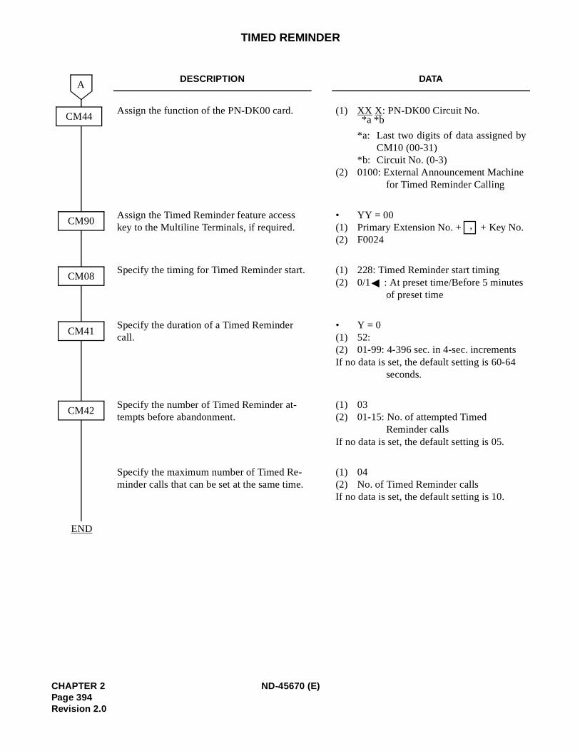
TIMED REMINDER
DESCRIPTION DATA
Assign the function of the PN-DK00 card. (1) XX X: PN-DK00 Circuit No.
*a: Last two digits of data assigned byCM10 (00-31)
*b: Circuit No. (0-3)(2) 0100: External Announcement Machine
for Timed Reminder Calling
Assign the Timed Reminder feature access key to the Multiline Terminals, if required.
• YY = 00(1) Primary Extension No. + + Key No.(2) F0024
Specify the timing for Timed Reminder start. (1) 228: Timed Reminder start timing(2) 0/1 : At preset time/Before 5 minutes
of preset time
Specify the duration of a Timed Reminder call.
• Y = 0(1) 52:(2) 01-99: 4-396 sec. in 4-sec. incrementsIf no data is set, the default setting is 60-64
seconds.
Specify the number of Timed Reminder at-tempts before abandonment.
(1) 03(2) 01-15: No. of attempted Timed
Reminder callsIf no data is set, the default setting is 05.
Specify the maximum number of Timed Re-minder calls that can be set at the same time.
(1) 04(2) No. of Timed Reminder callsIf no data is set, the default setting is 10.
CM90
A
CM08
CM41
CM42
END
CM44 *b*a
,
CHAPTER 2 ND-45670 (E)Page 394Revision 2.0
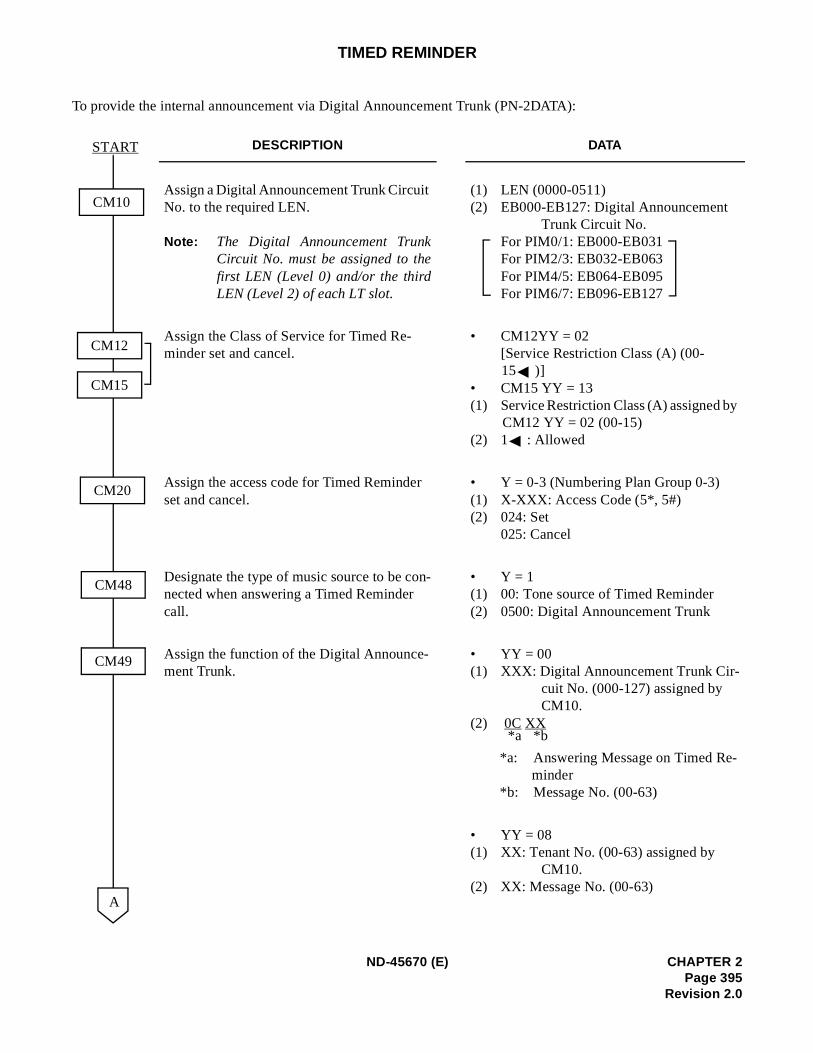
y
TIMED REMINDER
To provide the internal announcement via Digital Announcement Trunk (PN-2DATA):
DESCRIPTION DATA
Assign a Digital Announcement Trunk Circuit No. to the required LEN.
Note: The Digital Announcement TrunkCircuit No. must be assigned to thefirst LEN (Level 0) and/or the thirdLEN (Level 2) of each LT slot.
(1) LEN (0000-0511) (2) EB000-EB127: Digital Announcement
Trunk Circuit No.For PIM0/1: EB000-EB031 For PIM2/3: EB032-EB063 For PIM4/5: EB064-EB095 For PIM6/7: EB096-EB127
Assign the Class of Service for Timed Re-minder set and cancel.
• CM12YY = 02[Service Restriction Class (A) (00-15 )]
• CM15 YY = 13 (1) Service Restriction Class (A) assigned b
CM12 YY = 02 (00-15)(2) 1 : Allowed
Assign the access code for Timed Reminder set and cancel.
• Y = 0-3 (Numbering Plan Group 0-3) (1) X-XXX: Access Code (5*, 5#) (2) 024: Set
025: Cancel
Designate the type of music source to be con-nected when answering a Timed Reminder call.
• Y = 1 (1) 00: Tone source of Timed Reminder(2) 0500: Digital Announcement Trunk
Assign the function of the Digital Announce-ment Trunk.
• YY = 00(1) XXX: Digital Announcement Trunk Cir-
cuit No. (000-127) assigned by CM10.
(2) 0C XX
*a: Answering Message on Timed Re-minder
*b: Message No. (00-63)
• YY = 08(1) XX: Tenant No. (00-63) assigned by
CM10.(2) XX: Message No. (00-63)
START
A
CM20
CM48
CM12
CM15
CM10
CM49
*b*a
ND-45670 (E) CHAPTER 2Page 395
Revision 2.0
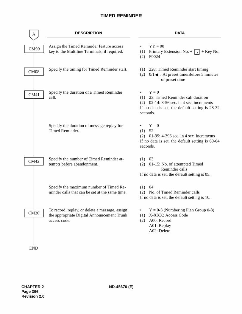
2
4
TIMED REMINDER
DESCRIPTION DATA
Assign the Timed Reminder feature access key to the Multiline Terminals, if required.
• YY = 00(1) Primary Extension No. + + Key No.(2) F0024
Specify the timing for Timed Reminder start. (1) 228: Timed Reminder start timing(2) 0/1 : At preset time/Before 5 minutes
of preset time
Specify the duration of a Timed Reminder call.
• Y = 0(1) 23: Timed Reminder call duration(2) 02-14: 8-56 sec. in 4 sec. incrementsIf no data is set, the default setting is 28-3seconds.
Specify the duration of message replay for Timed Reminder.
• Y = 0(1) 52(2) 01-99: 4-396 sec. in 4 sec. incrementsIf no data is set, the default setting is 60-6seconds.
Specify the number of Timed Reminder at-tempts before abandonment.
(1) 03(2) 01-15: No. of attempted Timed
Reminder callsIf no data is set, the default setting is 05.
Specify the maximum number of Timed Re-minder calls that can be set at the same time.
(1) 04(2) No. of Timed Reminder callsIf no data is set, the default setting is 10.
To record, replay, or delete a message, assign the appropriate Digital Announcement Trunk access code.
• Y = 0-3 (Numbering Plan Group 0-3)(1) X-XXX: Access Code(2) A00: Record
A01: ReplayA02: Delete
CM90
CM08
CM42
A
END
CM41
CM20
,
CHAPTER 2 ND-45670 (E)Page 396Revision 2.0
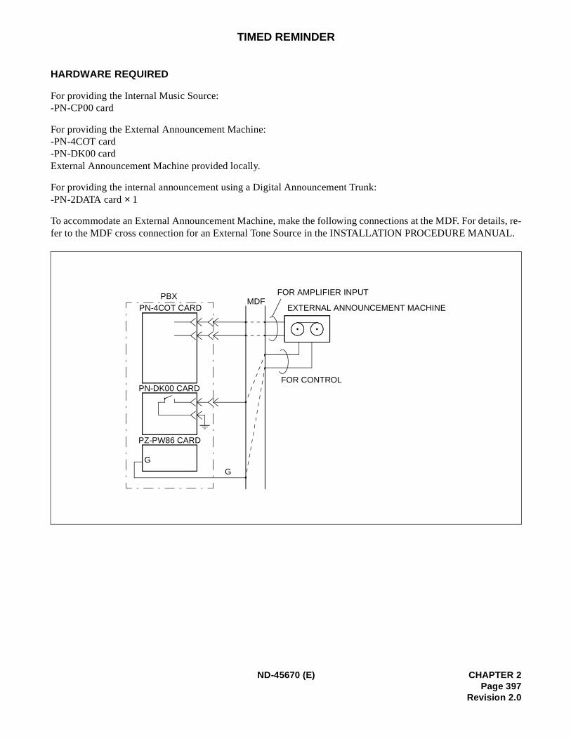
tails, re-L.
TIMED REMINDER
HARDWARE REQUIRED
For providing the Internal Music Source: -PN-CP00 card
For providing the External Announcement Machine: -PN-4COT card -PN-DK00 card External Announcement Machine provided locally.
For providing the internal announcement using a Digital Announcement Trunk: -PN-2DATA card × 1
To accommodate an External Announcement Machine, make the following connections at the MDF. For defer to the MDF cross connection for an External Tone Source in the INSTALLATION PROCEDURE MANUA
PBXPN-4COT CARD
PN-DK00 CARD
MDFEXTERNAL ANNOUNCEMENT MACHINE
PZ-PW86 CARD
GG
FOR AMPLIFIER INPUT
FOR CONTROL
ND-45670 (E) CHAPTER 2Page 397
Revision 2.0
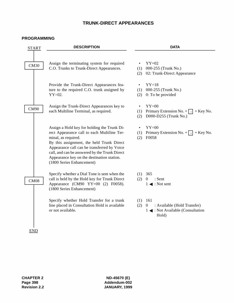
TRUNK-DIRECT APPEARANCES
PROGRAMMING
DESCRIPTION DATA
Assign the terminating system for requiredC.O. Trunks to Trunk-Direct Appearances.
• YY=02(1) 000-255 (Trunk No.) (2) 02: Trunk-Direct Appearance
Provide the Trunk-Direct Appearances fea-ture to the required C.O. trunk assigned byYY=02.
• YY=18(1) 000-255 (Trunk No.) (2) 0: To be provided
Assign the Trunk-Direct Appearances key toeach Multiline Terminal, as required.
• YY=00(1) Primary Extension No. + + Key No. (2) D000-D255 (Trunk No.)
Assign a Hold key for holding the Trunk Di-rect Appearance call to each Multiline Ter-minal, as required.By this assignment, the held Trunk DirectAppearance call can be transferred by Voicecall, and can be answered by the Trunk DirectAppearance key on the destination station.(1800 Series Enhancement)
• YY=00(1) Primary Extension No. + + Key No. (2) F0058
Specify whether a Dial Tone is sent when thecall is held by the Hold key for Trunk DirectAppearance (CM90 YY=00 (2) F0058).(1800 Series Enhancement)
(1) 365 (2) 0 : Sent
1 : Not sent
Specify whether Hold Transfer for a trunkline placed in Consultation Hold is availableor not available.
(1) 161 (2) 0 : Available (Hold Transfer)
1 : Not Available (Consultation Hold)
CM30
CM90
START
CM08
END
,
,
CHAPTER 2 ND-45670 (E)Page 398 Addendum-002Revision 2.2 JANUARY, 1999
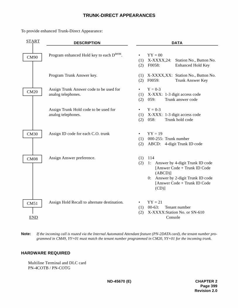
er pro-nk.
TRUNK-DIRECT APPEARANCES
To provide enhanced Trunk-Direct Appearance:
Note: If the incoming call is routed via the Internal Automated Attendant feature (PN-2DATA card), the tenant numbgrammed in CM49, YY=01 must match the tenant number programmed in CM20, YY=01 for the incoming tru
HARDWARE REQUIRED
Multiline Terminal and DLC cardPN-4COTB / PN-COTG
DESCRIPTION DATA
Program enhanced Hold key to each Dterm.
Program Trunk Answer key.
• YY = 00(1) X-XXXX,24: Station No., Button No.(2) F0058: Enhanced Hold Key
(1) X-XXXX,XX: Station No., Button No.(2) F0059: Trunk Answer Key
Assign Trunk Answer code to be used for analog telephones.
Assign Trunk Hold code to be used for analog telephones.
• Y = 0-3(1) X-XXX: 1-3 digit access code(2) 059: Trunk answer code
• Y = 0-3(1) X-XXX: 1-3 digit access code(2) 058: Trunk hold code
Assign ID code for each C.O. trunk • YY = 19(1) 000-255: Trunk number(2) ABCD: 4-digit Trunk ID code
Assign Answer preference. (1) 114(2) 1: Answer by 4-digit Trunk ID code
[Answer Code + Trunk ID Code (ABCD)]
0: Answer by 2-digit Trunk ID code[Answer Code + Trunk ID Code (CD)]
Assign Hold Recall to alternate destination. • YY = 21(1) 00-63: Tenant number(2) X-XXXX:Station No. or SN-610
Console
START
END
CM90
CM20
CM30
CM08
CM51
ND-45670 (E) CHAPTER 2Page 399
Revision 2.0
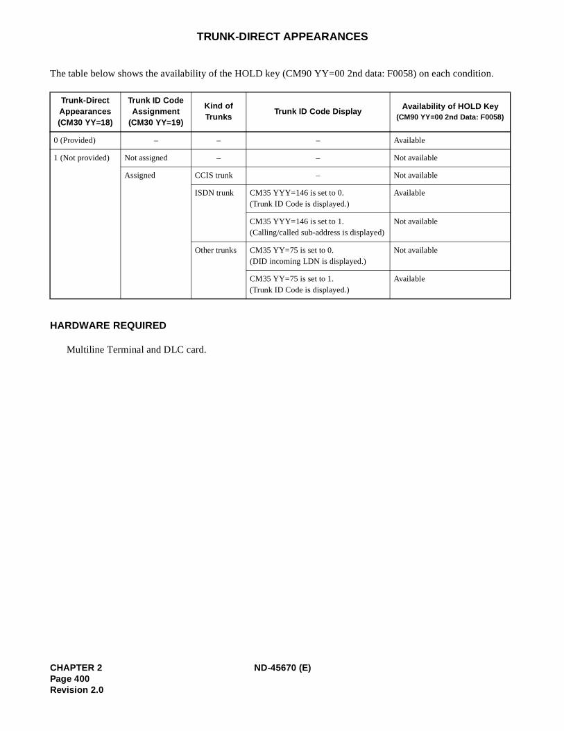
.
TRUNK-DIRECT APPEARANCES
The table below shows the availability of the HOLD key (CM90 YY=00 2nd data: F0058) on each condition
HARDWARE REQUIRED
Multiline Terminal and DLC card.
Trunk-DirectAppearances(CM30 YY=18)
Trunk ID Code Assignment
(CM30 YY=19)
Kind of Trunks
Trunk ID Code DisplayAvailability of HOLD Key
(CM90 YY=00 2nd Data: F0058)
0 (Provided) – – – Available
1 (Not provided) Not assigned – – Not available
Assigned CCIS trunk – Not available
ISDN trunk CM35 YYY=146 is set to 0.(Trunk ID Code is displayed.)
Available
CM35 YYY=146 is set to 1.(Calling/called sub-address is displayed)
Not available
Other trunks CM35 YY=75 is set to 0.(DID incoming LDN is displayed.)
Not available
CM35 YY=75 is set to 1.(Trunk ID Code is displayed.)
Available
CHAPTER 2 ND-45670 (E)Page 400Revision 2.0
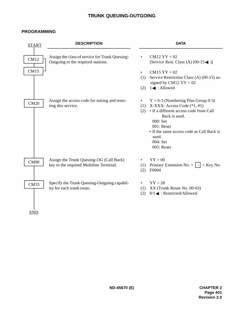
-
is
TRUNK QUEUING-OUTGOING
PROGRAMMING
DESCRIPTION DATA
Assign the class of service for Trunk Queuing-Outgoing to the required stations.
• CM12 YY = 02 [Service Rest. Class (A) (00-15 )]
• CM15 YY = 02 (1) Service Restriction Class (A) (00-15) as
signed by CM12 YY = 02(2) 1 : Allowed
Assign the access code for setting and reset-ting this service.
• Y = 0-3 (Numbering Plan Group 0-3) (1) X-XXX: Access Code (*1, #1) (2) • If a different access code from Call
Back is used. 000: Set 001: Reset
• If the same access code as Call Back used. 004: Set 005: Reset
Assign the Trunk Queuing-OG (Call Back) key to the required Multiline Terminal.
• YY = 00(1) Primary Extension No. + + Key No.(2) F0004
Specify the Trunk Queuing-Outgoing capabil-ity for each trunk route.
• YY = 28(1) XX (Trunk Route No. 00-63) (2) 0/1 : Restricted/Allowed
CM20
END
START
CM35
CM90
CM12
CM15
,
ND-45670 (E) CHAPTER 2Page 401
Revision 2.0
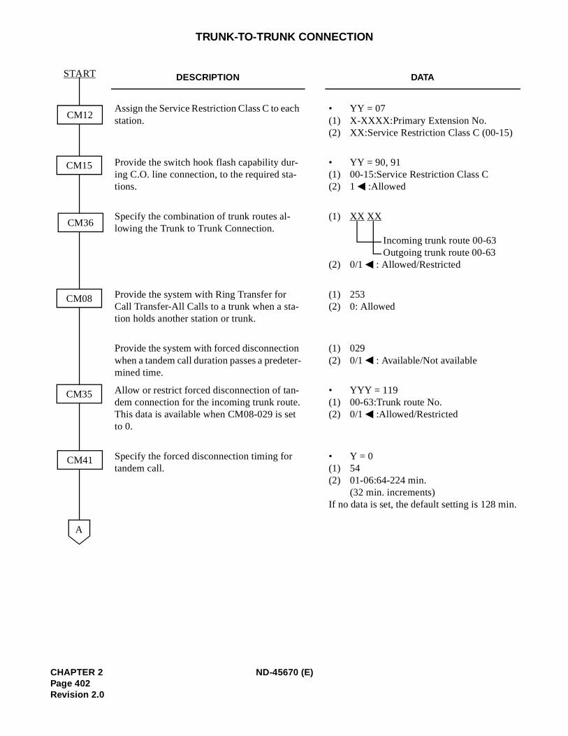
.
TRUNK-TO-TRUNK CONNECTION
DESCRIPTION DATA
Assign the Service Restriction Class C to each station.
• YY = 07(1) X-XXXX:Primary Extension No.(2) XX:Service Restriction Class C (00-15)
Provide the switch hook flash capability dur-ing C.O. line connection, to the required sta-tions.
• YY = 90, 91(1) 00-15:Service Restriction Class C(2) 1 :Allowed
Specify the combination of trunk routes al-lowing the Trunk to Trunk Connection.
(1) XX XX
Incoming trunk route 00-63Outgoing trunk route 00-63
(2) 0/1 : Allowed/Restricted
Provide the system with Ring Transfer for Call Transfer-All Calls to a trunk when a sta-tion holds another station or trunk.
(1) 253(2) 0: Allowed
Provide the system with forced disconnection when a tandem call duration passes a predeter-mined time.
(1) 029(2) 0/1 : Available/Not available
Allow or restrict forced disconnection of tan-dem connection for the incoming trunk route.This data is available when CM08-029 is set to 0.
• YYY = 119(1) 00-63:Trunk route No.(2) 0/1 :Allowed/Restricted
Specify the forced disconnection timing for tandem call.
• Y = 0(1) 54(2) 01-06:64-224 min.
(32 min. increments)If no data is set, the default setting is 128 min
CM12
A
CM08
CM35
CM15
CM36
CM41
START
CHAPTER 2 ND-45670 (E)Page 402Revision 2.0
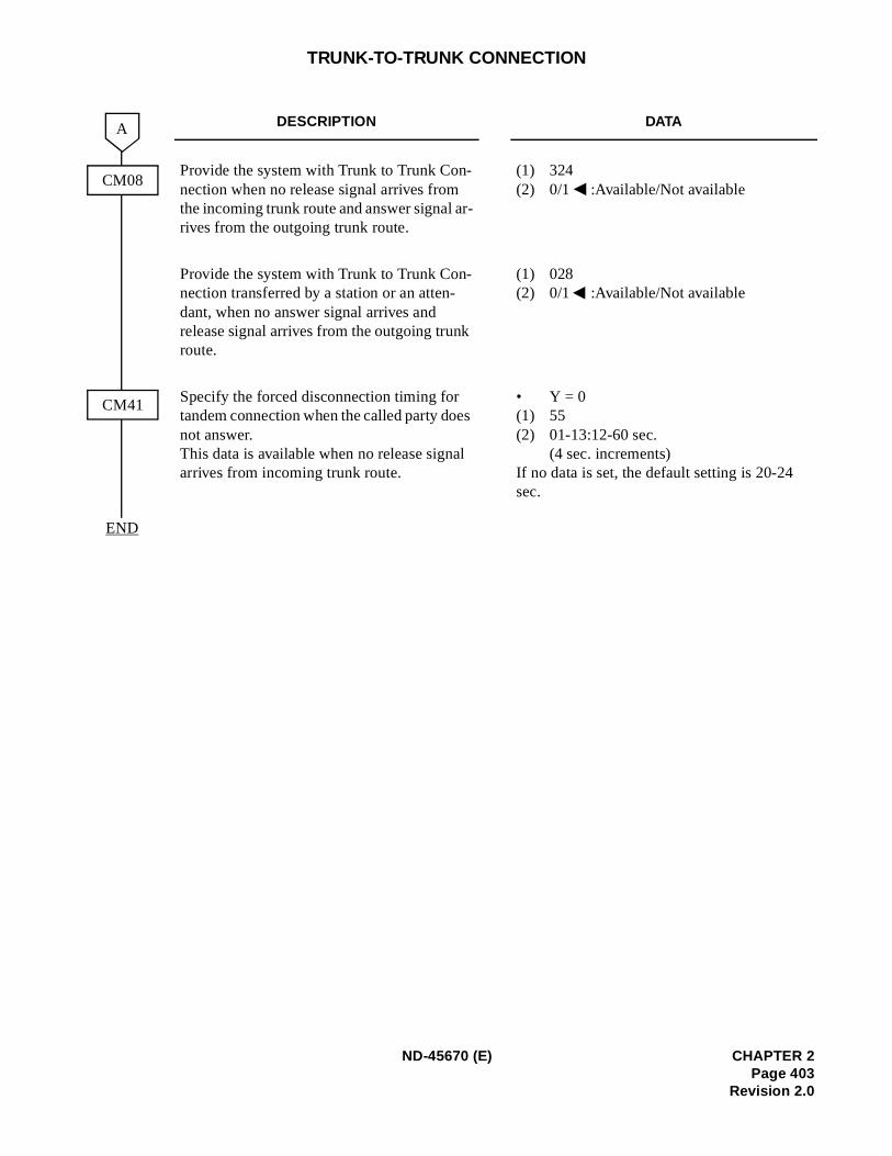
TRUNK-TO-TRUNK CONNECTION
DESCRIPTION DATA
Provide the system with Trunk to Trunk Con-nection when no release signal arrives from the incoming trunk route and answer signal ar-rives from the outgoing trunk route.
(1) 324(2) 0/1 :Available/Not available
Provide the system with Trunk to Trunk Con-nection transferred by a station or an atten-dant, when no answer signal arrives and release signal arrives from the outgoing trunk route.
(1) 028(2) 0/1 :Available/Not available
Specify the forced disconnection timing for tandem connection when the called party does not answer.This data is available when no release signal arrives from incoming trunk route.
• Y = 0(1) 55(2) 01-13:12-60 sec.
(4 sec. increments)If no data is set, the default setting is 20-24 sec.
CM41
END
CM08
A
ND-45670 (E) CHAPTER 2Page 403
Revision 2.0
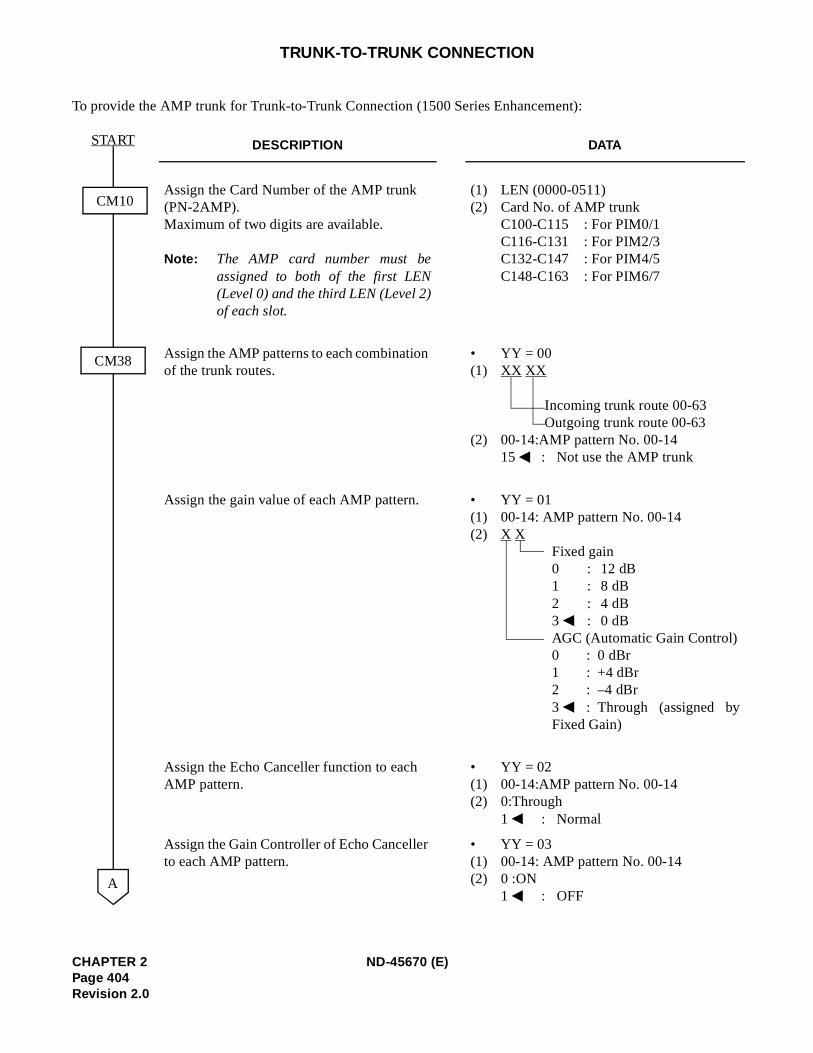
TRUNK-TO-TRUNK CONNECTION
To provide the AMP trunk for Trunk-to-Trunk Connection (1500 Series Enhancement):
DESCRIPTION DATA
Assign the Card Number of the AMP trunk (PN-2AMP).Maximum of two digits are available.
Note: The AMP card number must beassigned to both of the first LEN(Level 0) and the third LEN (Level 2)of each slot.
(1) LEN (0000-0511)(2) Card No. of AMP trunk
C100-C115 : For PIM0/1C116-C131 : For PIM2/3C132-C147 : For PIM4/5C148-C163 : For PIM6/7
Assign the AMP patterns to each combination of the trunk routes.
• YY = 00(1) XX XX
Incoming trunk route 00-63Outgoing trunk route 00-63
(2) 00-14:AMP pattern No. 00-1415 : Not use the AMP trunk
Assign the gain value of each AMP pattern. • YY = 01(1) 00-14: AMP pattern No. 00-14(2) X X
Fixed gain0 : 12 dB1 : 8 dB2 : 4 dB3 : 0 dBAGC (Automatic Gain Control)0 : 0 dBr1 : +4 dBr2 : –4 dBr3 : Through (assigned byFixed Gain)
Assign the Echo Canceller function to each AMP pattern.
• YY = 02(1) 00-14:AMP pattern No. 00-14(2) 0:Through
1 : Normal
Assign the Gain Controller of Echo Canceller to each AMP pattern.
• YY = 03(1) 00-14: AMP pattern No. 00-14(2) 0 :ON
1 : OFF
CM10
A
CM38
START
CHAPTER 2 ND-45670 (E)Page 404Revision 2.0
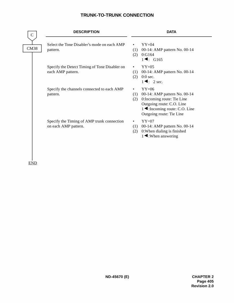
TRUNK-TO-TRUNK CONNECTION
DESCRIPTION DATA
Select the Tone Disabler’s mode on each AMP pattern.
• YY=04(1) 00-14: AMP pattern No. 00-14(2) 0:G164
1 : G165
Specify the Detect Timing of Tone Disabler on each AMP pattern.
• YY=05(1) 00-14: AMP pattern No. 00-14(2) 0:0 sec.
1 : 2 sec.
Specify the channels connected to each AMP pattern.
• YY=06(1) 00-14: AMP pattern No. 00-14(2) 0:Incoming route: Tie Line
Outgoing route: C.O. Line1 :Incoming route: C.O. LineOutgoing route: Tie Line
Specify the Timing of AMP trunk connection on each AMP pattern.
• YY=07(1) 00-14: AMP pattern No. 00-14(2) 0:When dialing is finished
1 :When answering
CM38
C
END
ND-45670 (E) CHAPTER 2Page 405
Revision 2.0
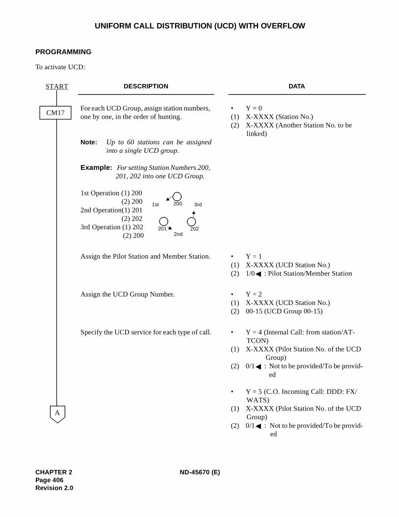
UNIFORM CALL DISTRIBUTION (UCD) WITH OVERFLOW
PROGRAMMING
To activate UCD:
DESCRIPTION DATA
For each UCD Group, assign station numbers, one by one, in the order of hunting.
Note: Up to 60 stations can be assignedinto a single UCD group.
Example: For setting Station Numbers 200, 201, 202 into one UCD Group.
1st Operation (1) 200 (2) 200
2nd Operation(1) 201(2) 202
3rd Operation (1) 202(2) 200
• Y = 0(1) X-XXXX (Station No.)(2) X-XXXX (Another Station No. to be
linked)
Assign the Pilot Station and Member Station. • Y = 1(1) X-XXXX (UCD Station No.) (2) 1/0 : Pilot Station/Member Station
Assign the UCD Group Number. • Y = 2(1) X-XXXX (UCD Station No.) (2) 00-15 (UCD Group 00-15)
Specify the UCD service for each type of call. • Y = 4 (Internal Call: from station/AT-TCON)
(1) X-XXXX (Pilot Station No. of the UCD Group)
(2) 0/1 : Not to be provided/To be provid-ed
• Y = 5 (C.O. Incoming Call: DDD: FX/WATS)
(1) X-XXXX (Pilot Station No. of the UCD Group)
(2) 0/1 : Not to be provided/To be provid-ed
CM17
START
A
3rd1st
2nd
200
202201
CHAPTER 2 ND-45670 (E)Page 406Revision 2.0
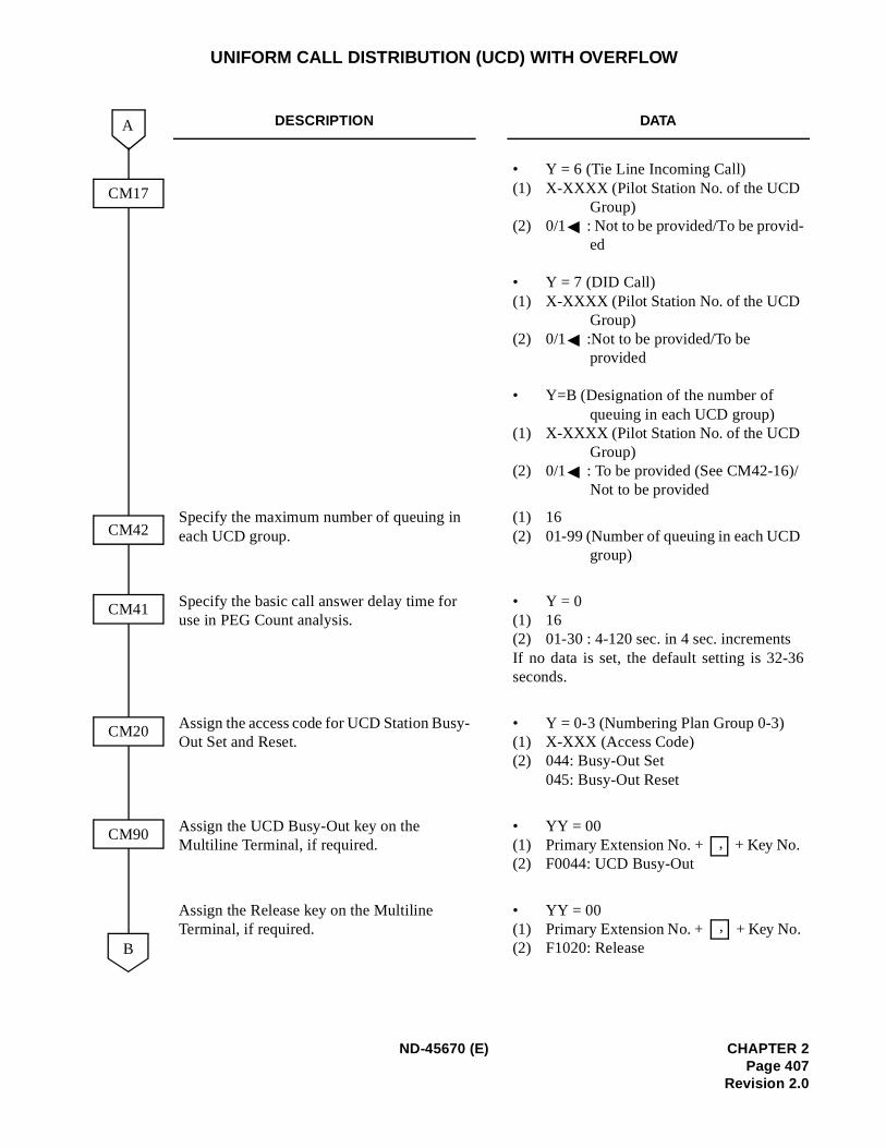
6
UNIFORM CALL DISTRIBUTION (UCD) WITH OVERFLOW
DESCRIPTION DATA
• Y = 6 (Tie Line Incoming Call) (1) X-XXXX (Pilot Station No. of the UCD
Group)(2) 0/1 : Not to be provided/To be provid-
ed
• Y = 7 (DID Call) (1) X-XXXX (Pilot Station No. of the UCD
Group)(2) 0/1 :Not to be provided/To be
provided
• Y=B (Designation of the number of queuing in each UCD group)
(1) X-XXXX (Pilot Station No. of the UCD Group)
(2) 0/1 : To be provided (See CM42-16)/Not to be provided
Specify the maximum number of queuing in each UCD group.
(1) 16(2) 01-99 (Number of queuing in each UCD
group)
Specify the basic call answer delay time for use in PEG Count analysis.
• Y = 0(1) 16(2) 01-30 : 4-120 sec. in 4 sec. incrementsIf no data is set, the default setting is 32-3seconds.
Assign the access code for UCD Station Busy-Out Set and Reset.
• Y = 0-3 (Numbering Plan Group 0-3)(1) X-XXX (Access Code)(2) 044: Busy-Out Set
045: Busy-Out Reset
Assign the UCD Busy-Out key on the Multiline Terminal, if required.
• YY = 00(1) Primary Extension No. + + Key No. (2) F0044: UCD Busy-Out
Assign the Release key on the Multiline Terminal, if required.
• YY = 00(1) Primary Extension No. + + Key No. (2) F1020: Release B
A
CM41
CM20
CM90
CM17
CM42
,
,
ND-45670 (E) CHAPTER 2Page 407
Revision 2.0
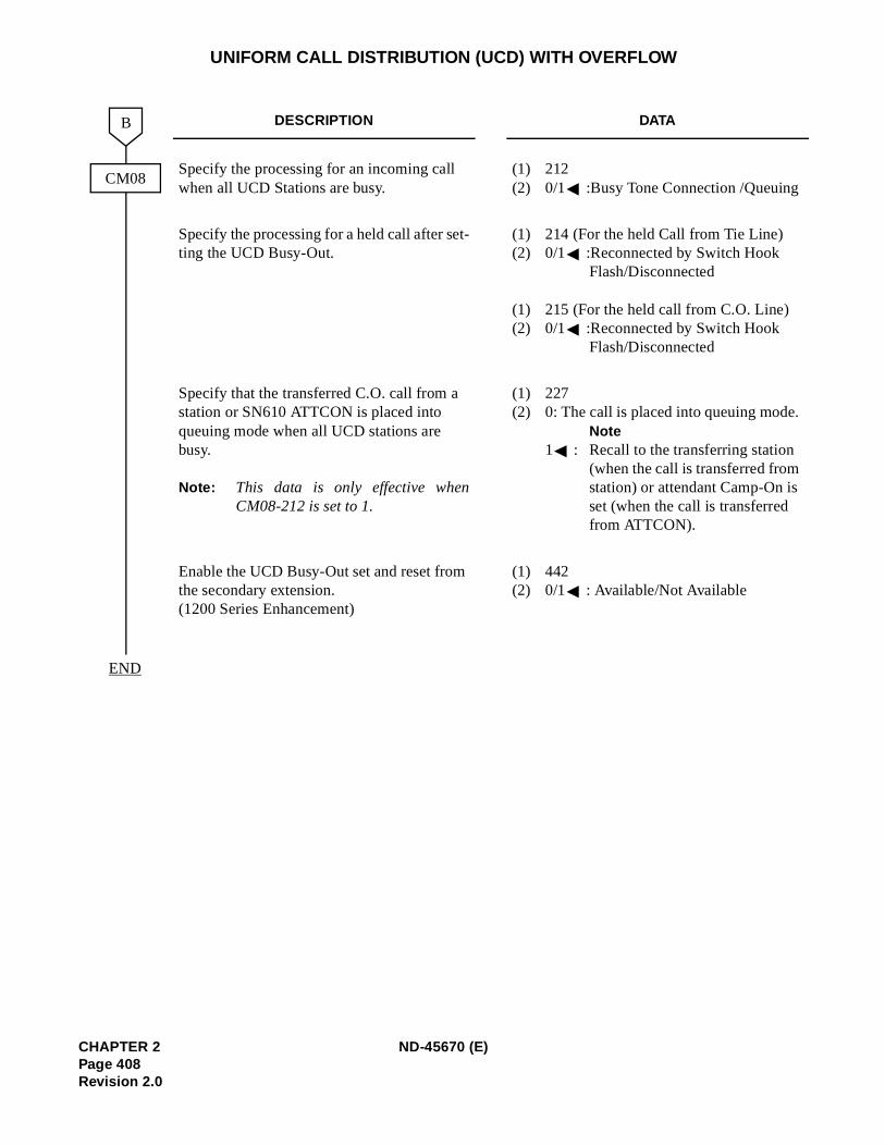
UNIFORM CALL DISTRIBUTION (UCD) WITH OVERFLOW
DESCRIPTION DATA
Specify the processing for an incoming call when all UCD Stations are busy.
(1) 212 (2) 0/1 :Busy Tone Connection /Queuing
Specify the processing for a held call after set-ting the UCD Busy-Out.
(1) 214 (For the held Call from Tie Line)(2) 0/1 :Reconnected by Switch Hook
Flash/Disconnected
(1) 215 (For the held call from C.O. Line)(2) 0/1 :Reconnected by Switch Hook
Flash/Disconnected
Specify that the transferred C.O. call from a station or SN610 ATTCON is placed into queuing mode when all UCD stations are busy.
Note: This data is only effective whenCM08-212 is set to 1.
(1) 227 (2) 0: The call is placed into queuing mode.
Note1 : Recall to the transferring station
(when the call is transferred from station) or attendant Camp-On is set (when the call is transferred from ATTCON).
Enable the UCD Busy-Out set and reset from the secondary extension.(1200 Series Enhancement)
(1) 442 (2) 0/1 : Available/Not Available
B
END
CM08
CHAPTER 2 ND-45670 (E)Page 408Revision 2.0
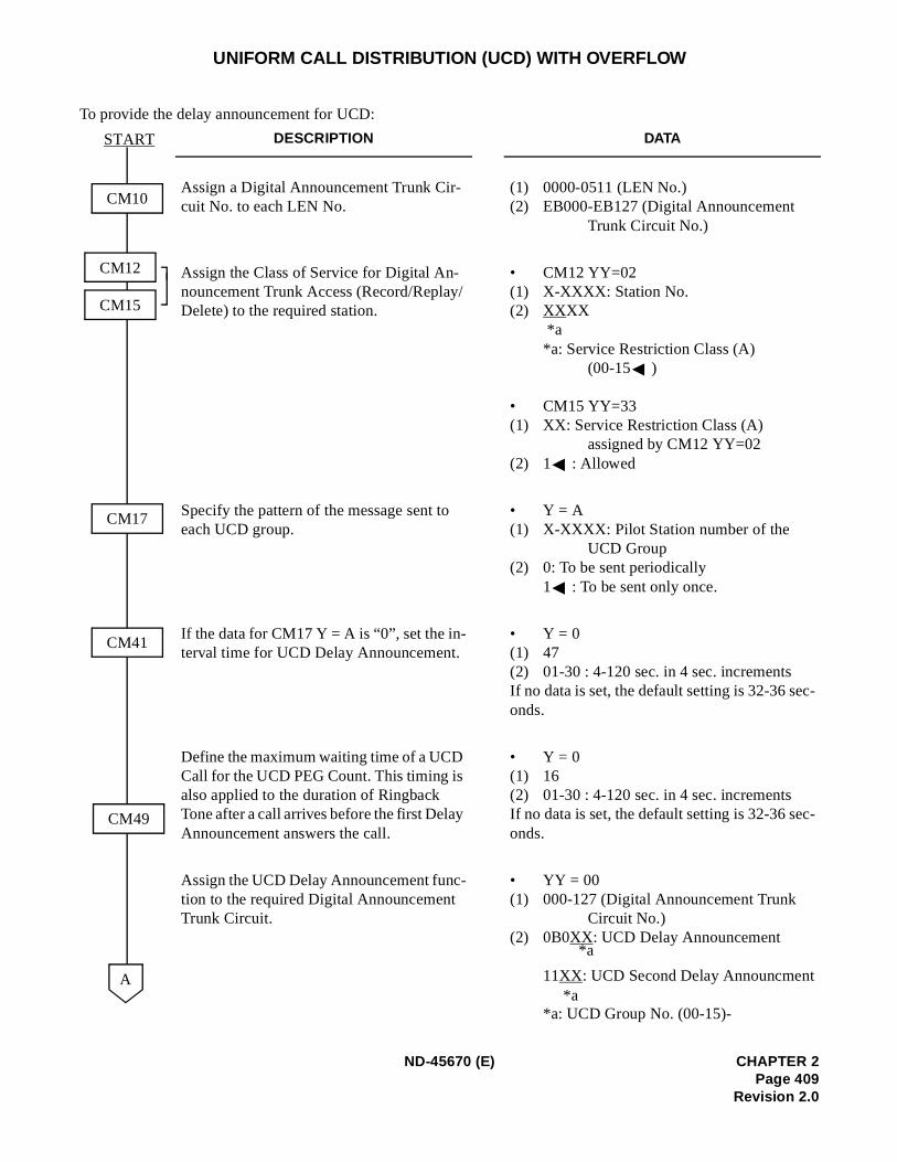
c-
c-
UNIFORM CALL DISTRIBUTION (UCD) WITH OVERFLOW
To provide the delay announcement for UCD:
DESCRIPTION DATA
Assign a Digital Announcement Trunk Cir-cuit No. to each LEN No.
(1) 0000-0511 (LEN No.)(2) EB000-EB127 (Digital Announcement
Trunk Circuit No.)
Assign the Class of Service for Digital An-nouncement Trunk Access (Record/Replay/Delete) to the required station.
• CM12 YY=02(1) X-XXXX: Station No.(2) XXXX
*a *a: Service Restriction Class (A)
(00-15 )
• CM15 YY=33(1) XX: Service Restriction Class (A)
assigned by CM12 YY=02(2) 1 : Allowed
Specify the pattern of the message sent to each UCD group.
• Y = A(1) X-XXXX: Pilot Station number of the
UCD Group(2) 0: To be sent periodically
1 : To be sent only once.
If the data for CM17 Y = A is “0”, set the in-terval time for UCD Delay Announcement.
• Y = 0(1) 47(2) 01-30 : 4-120 sec. in 4 sec. incrementsIf no data is set, the default setting is 32-36 seonds.
Define the maximum waiting time of a UCD Call for the UCD PEG Count. This timing is also applied to the duration of Ringback Tone after a call arrives before the first Delay Announcement answers the call.
• Y = 0(1) 16(2) 01-30 : 4-120 sec. in 4 sec. incrementsIf no data is set, the default setting is 32-36 seonds.
Assign the UCD Delay Announcement func-tion to the required Digital Announcement Trunk Circuit.
• YY = 00(1) 000-127 (Digital Announcement Trunk
Circuit No.)(2) 0B0XX: UCD Delay Announcement
11XX: UCD Second Delay Announcment
*a: UCD Group No. (00-15)-
START
CM10
CM17
CM41
CM49
CM12
CM15
A
*a
*a
ND-45670 (E) CHAPTER 2Page 409
Revision 2.0
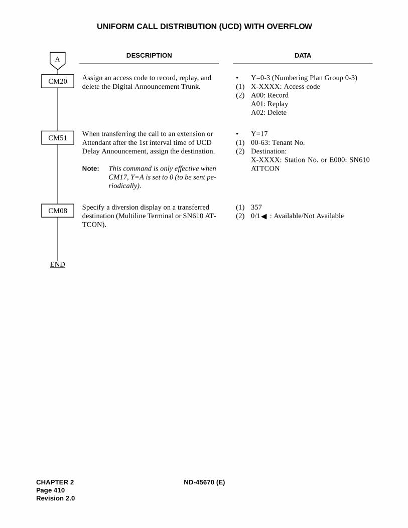
UNIFORM CALL DISTRIBUTION (UCD) WITH OVERFLOW
DESCRIPTION DATA
Assign an access code to record, replay, and delete the Digital Announcement Trunk.
• Y=0-3 (Numbering Plan Group 0-3)(1) X-XXXX: Access code(2) A00: Record
A01: ReplayA02: Delete
When transferring the call to an extension or Attendant after the 1st interval time of UCD Delay Announcement, assign the destination.
Note: This command is only effective whenCM17, Y=A is set to 0 (to be sent pe-riodically).
• Y=17(1) 00-63: Tenant No.(2) Destination:
X-XXXX: Station No. or E000: SN610ATTCON
Specify a diversion display on a transferred destination (Multiline Terminal or SN610 AT-TCON).
(1) 357(2) 0/1 : Available/Not Available
CM20
A
END
CM51
CM08
CHAPTER 2 ND-45670 (E)Page 410Revision 2.0
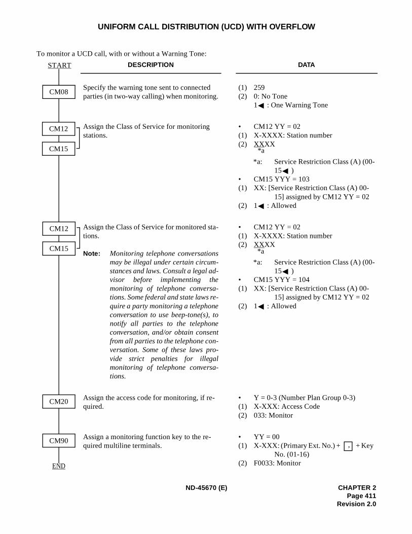
UNIFORM CALL DISTRIBUTION (UCD) WITH OVERFLOW
To monitor a UCD call, with or without a Warning Tone:
DESCRIPTION DATA
Specify the warning tone sent to connected parties (in two-way calling) when monitoring.
(1) 259 (2) 0: No Tone
1 : One Warning Tone
Assign the Class of Service for monitoring stations.
• CM12 YY = 02 (1) X-XXXX: Station number(2) XXXX
*a: Service Restriction Class (A) (00-15 )
• CM15 YYY = 103 (1) XX: [Service Restriction Class (A) 00-
15] assigned by CM12 YY = 02 (2) 1 : Allowed
Assign the Class of Service for monitored sta-tions.
Note: Monitoring telephone conversationsmay be illegal under certain circum-stances and laws. Consult a legal ad-visor before implementing themonitoring of telephone conversa-tions. Some federal and state laws re-quire a party monitoring a telephoneconversation to use beep-tone(s), tonotify all parties to the telephoneconversation, and/or obtain consentfrom all parties to the telephone con-versation. Some of these laws pro-vide strict penalties for illegalmonitoring of telephone conversa-tions.
• CM12 YY = 02 (1) X-XXXX: Station number (2) XXXX
*a: Service Restriction Class (A) (00-15 )
• CM15 YYY = 104 (1) XX: [Service Restriction Class (A) 00-
15] assigned by CM12 YY = 02(2) 1 : Allowed
Assign the access code for monitoring, if re-quired.
• Y = 0-3 (Number Plan Group 0-3)(1) X-XXX: Access Code(2) 033: Monitor
Assign a monitoring function key to the re-quired multiline terminals.
• YY = 00(1) X-XXX: (Primary Ext. No.) + + Key
No. (01-16) (2) F0033: Monitor
START
CM08
CM20
CM90
CM12
CM15
CM12
CM15
END
*a
*a
,
ND-45670 (E) CHAPTER 2Page 411
Revision 2.0

UNIFORM CALL DISTRIBUTION (UCD) WITH OVERFLOW
To provide the LEDs on the Multiline Terminal for UCD Call Waiting Indication:
DESCRIPTION DATA
Assign the incoming call to queuing mode when all UCD stations are busy.
(1) 212(2) 1 : Queuing
Specify the maximum number of queuing in each UCD group for controlling call waiting lamp of a Multiline Terminal.
Note: Depending on the number of queuingstation/trunk, lamp indication pat-tern on a Multiline Terminal is differ-ent as shown below:
(1) 15(2) 01-99 (Number of queuing in each UCD
group)If no data is set, the default setting is 01.
N=Number of queuing station/trunk
Assign the Call Waiting Indication LED to the required Multiline Terminal.
• YY = 00(1) Primary Extension No. + + Key No.(2) F1280: UCD Group 00
F1295: UCD Group 15
END
CM08
START
CM42
CM90
CONDITIONS LAMP INDICATION
2nd Data=01 Steady on red irrespective of number of queuing station/trunk1 ≤N < 2nd Data (2nd Data ≠ 01) Steady on red2nd Data ≤ N (2nd Data ≠ 01) Flashing red
,
| |
CHAPTER 2 ND-45670 (E)Page 412Revision 2.0
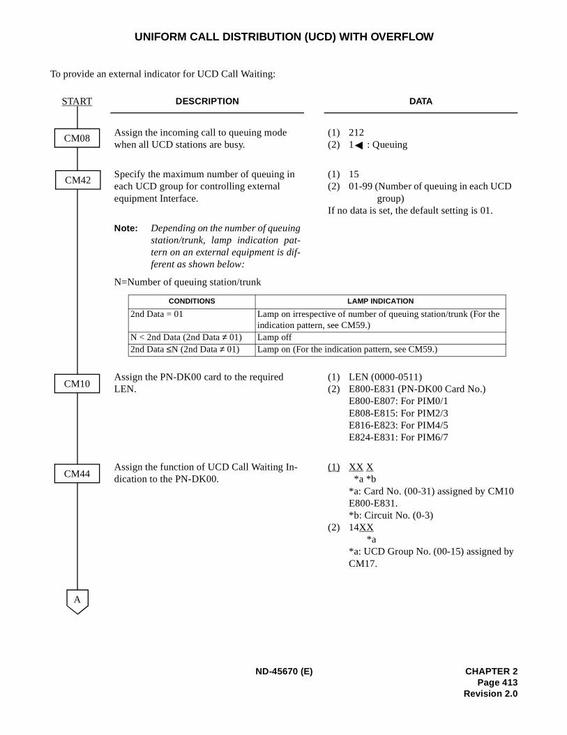
UNIFORM CALL DISTRIBUTION (UCD) WITH OVERFLOW
To provide an external indicator for UCD Call Waiting:
DESCRIPTION DATA
Assign the incoming call to queuing mode when all UCD stations are busy.
(1) 212(2) 1 : Queuing
Specify the maximum number of queuing in each UCD group for controlling external equipment Interface.
(1) 15(2) 01-99 (Number of queuing in each UCD
group)If no data is set, the default setting is 01.
Note: Depending on the number of queuingstation/trunk, lamp indication pat-tern on an external equipment is dif-ferent as shown below:
N=Number of queuing station/trunk
Assign the PN-DK00 card to the required LEN.
(1) LEN (0000-0511)(2) E800-E831 (PN-DK00 Card No.)
E800-E807: For PIM0/1E808-E815: For PIM2/3E816-E823: For PIM4/5E824-E831: For PIM6/7
Assign the function of UCD Call Waiting In-dication to the PN-DK00.
(1) XX X *a *b
*a: Card No. (00-31) assigned by CM10E800-E831. *b: Circuit No. (0-3)
(2) 14XX *a
*a: UCD Group No. (00-15) assigned byCM17.
START
CM08
CM42
CM10
CM44
A
CONDITIONS LAMP INDICATION
2nd Data = 01 Lamp on irrespective of number of queuing station/trunk (For theindication pattern, see CM59.)
N < 2nd Data (2nd Data ≠ 01) Lamp off2nd Data ≤N (2nd Data ≠ 01) Lamp on (For the indication pattern, see CM59.)
ND-45670 (E) CHAPTER 2Page 413
Revision 2.0
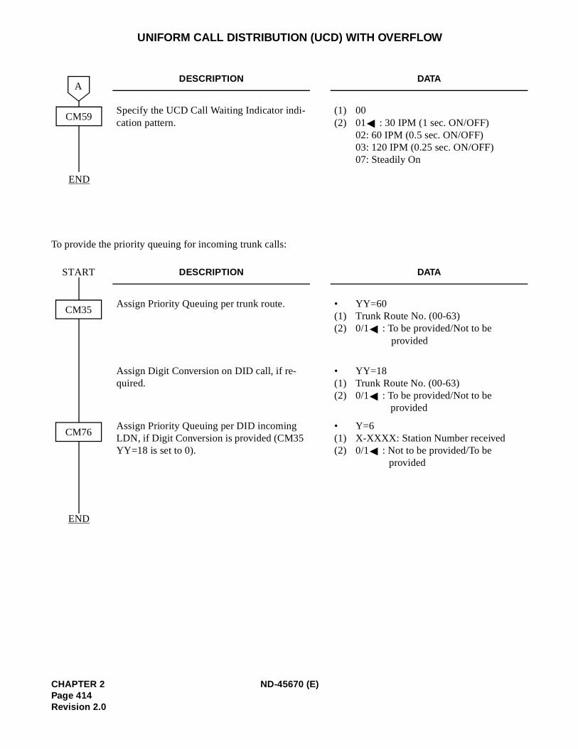
UNIFORM CALL DISTRIBUTION (UCD) WITH OVERFLOW
To provide the priority queuing for incoming trunk calls:
DESCRIPTION DATA
Specify the UCD Call Waiting Indicator indi-cation pattern.
(1) 00(2) 01 : 30 IPM (1 sec. ON/OFF)
02: 60 IPM (0.5 sec. ON/OFF)03: 120 IPM (0.25 sec. ON/OFF)07: Steadily On
DESCRIPTION DATA
Assign Priority Queuing per trunk route. • YY=60(1) Trunk Route No. (00-63)(2) 0/1 : To be provided/Not to be
provided
Assign Digit Conversion on DID call, if re-quired.
• YY=18(1) Trunk Route No. (00-63)(2) 0/1 : To be provided/Not to be
provided
Assign Priority Queuing per DID incoming LDN, if Digit Conversion is provided (CM35 YY=18 is set to 0).
• Y=6(1) X-XXXX: Station Number received(2) 0/1 : Not to be provided/To be
provided
END
A
CM59
START
END
CM35
CM76
CHAPTER 2 ND-45670 (E)Page 414Revision 2.0
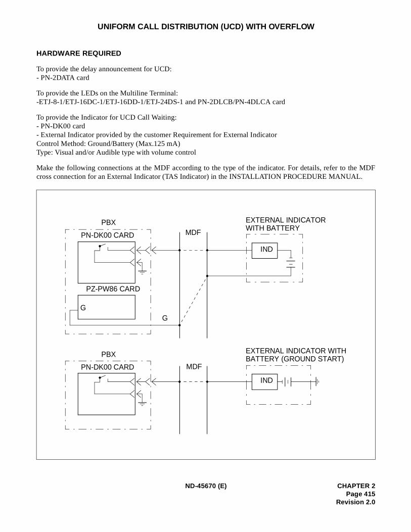
MDF
UNIFORM CALL DISTRIBUTION (UCD) WITH OVERFLOW
HARDWARE REQUIRED
To provide the delay announcement for UCD: - PN-2DATA card
To provide the LEDs on the Multiline Terminal:-ETJ-8-1/ETJ-16DC-1/ETJ-16DD-1/ETJ-24DS-1 and PN-2DLCB/PN-4DLCA card
To provide the Indicator for UCD Call Waiting: - PN-DK00 card - External Indicator provided by the customer Requirement for External Indicator Control Method: Ground/Battery (Max.125 mA) Type: Visual and/or Audible type with volume control
Make the following connections at the MDF according to the type of the indicator. For details, refer to thecross connection for an External Indicator (TAS Indicator) in the INSTALLATION PROCEDURE MANUAL.
PBX
PN-DK00 CARD
PZ-PW86 CARD
G
PBX
PN-DK00 CARD
MDF
MDF
EXTERNAL INDICATORWITH BATTERY
EXTERNAL INDICATOR WITHBATTERY (GROUND START)
IND
IND
G
ND-45670 (E) CHAPTER 2Page 415
Revision 2.0
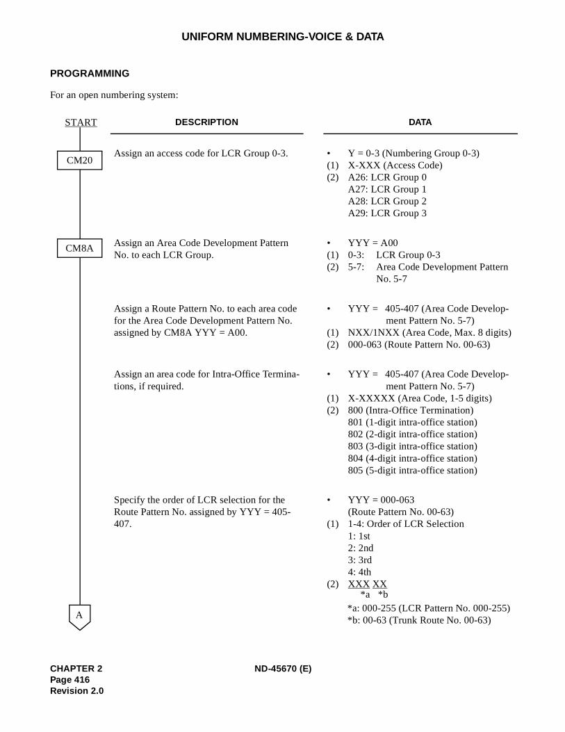
UNIFORM NUMBERING-VOICE & DATA
PROGRAMMING
For an open numbering system:
DESCRIPTION DATA
Assign an access code for LCR Group 0-3. • Y = 0-3 (Numbering Group 0-3)(1) X-XXX (Access Code) (2) A26: LCR Group 0
A27: LCR Group 1 A28: LCR Group 2 A29: LCR Group 3
Assign an Area Code Development Pattern No. to each LCR Group.
• YYY = A00(1) 0-3: LCR Group 0-3 (2) 5-7: Area Code Development Pattern
No. 5-7
Assign a Route Pattern No. to each area code for the Area Code Development Pattern No. assigned by CM8A YYY = A00.
• YYY = 405-407 (Area Code Develop-ment Pattern No. 5-7)
(1) NXX/1NXX (Area Code, Max. 8 digits) (2) 000-063 (Route Pattern No. 00-63)
Assign an area code for Intra-Office Termina-tions, if required.
• YYY = 405-407 (Area Code Develop-ment Pattern No. 5-7)
(1) X-XXXXX (Area Code, 1-5 digits) (2) 800 (Intra-Office Termination)
801 (1-digit intra-office station) 802 (2-digit intra-office station) 803 (3-digit intra-office station)804 (4-digit intra-office station) 805 (5-digit intra-office station)
Specify the order of LCR selection for the Route Pattern No. assigned by YYY = 405-407.
• YYY = 000-063(Route Pattern No. 00-63)
(1) 1-4: Order of LCR Selection 1: 1st2: 2nd3: 3rd4: 4th
(2) XXX XX
*a: 000-255 (LCR Pattern No. 000-255)*b: 00-63 (Trunk Route No. 00-63)
CM20
START
CM8A
A
*b*a
CHAPTER 2 ND-45670 (E)Page 416Revision 2.0
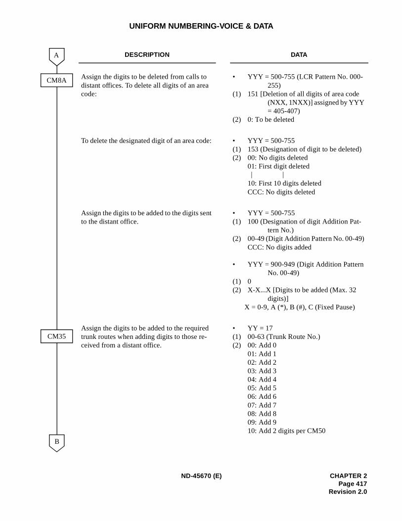
UNIFORM NUMBERING-VOICE & DATA
DESCRIPTION DATA
Assign the digits to be deleted from calls to distant offices. To delete all digits of an area code:
• YYY = 500-755 (LCR Pattern No. 000-255)
(1) 151 [Deletion of all digits of area code (NXX, 1NXX)] assigned by YYY = 405-407)
(2) 0: To be deleted
To delete the designated digit of an area code: • YYY = 500-755(1) 153 (Designation of digit to be deleted)(2) 00: No digits deleted
01: First digit deleted
10: First 10 digits deletedCCC: No digits deleted
Assign the digits to be added to the digits sent to the distant office.
• YYY = 500-755(1) 100 (Designation of digit Addition Pat-
tern No.) (2) 00-49 (Digit Addition Pattern No. 00-49)
CCC: No digits added
• YYY = 900-949 (Digit Addition Pattern No. 00-49)
(1) 0 (2) X-X...X [Digits to be added (Max. 32
digits)] X = 0-9, A (*), B (#), C (Fixed Pause)
Assign the digits to be added to the required trunk routes when adding digits to those re-ceived from a distant office.
• YY = 17 (1) 00-63 (Trunk Route No.) (2) 00: Add 0
01: Add 102: Add 203: Add 304: Add 405: Add 506: Add 607: Add 708: Add 809: Add 910: Add 2 digits per CM50
CM35
CM8A
A
B
| |
ND-45670 (E) CHAPTER 2Page 417
Revision 2.0
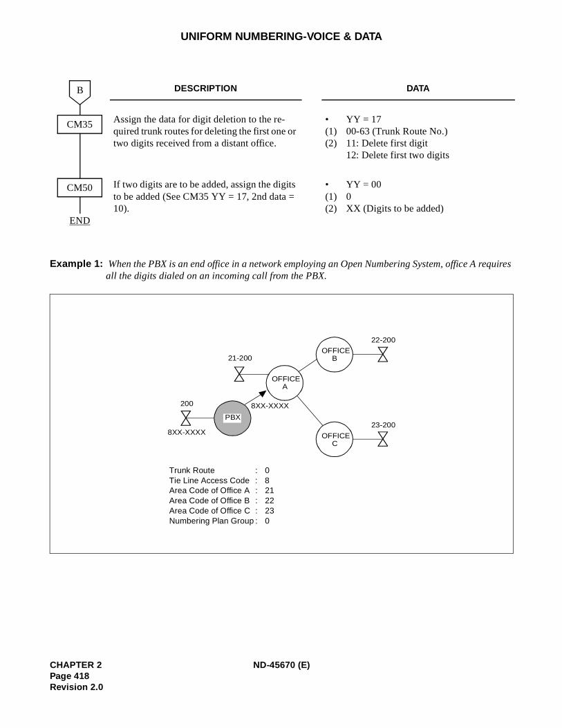
UNIFORM NUMBERING-VOICE & DATA
Example 1: When the PBX is an end office in a network employing an Open Numbering System, office A requires all the digits dialed on an incoming call from the PBX.
DESCRIPTION DATA
Assign the data for digit deletion to the re-quired trunk routes for deleting the first one or two digits received from a distant office.
• YY = 17(1) 00-63 (Trunk Route No.) (2) 11: Delete first digit
12: Delete first two digits
If two digits are to be added, assign the digits to be added (See CM35 YY = 17, 2nd data = 10).
• YY = 00(1) 0 (2) XX (Digits to be added)
CM50
CM35
B
END
22-200
OFFICEB
OFFICEC
OFFICEA
21-200
200
8XX-XXXX
8XX-XXXX
23-200PBX
Trunk Route : 0Tie Line Access Code : 8Area Code of Office A : 21Area Code of Office B : 22Area Code of Office C : 23Numbering Plan Group : 0
CHAPTER 2 ND-45670 (E)Page 418Revision 2.0
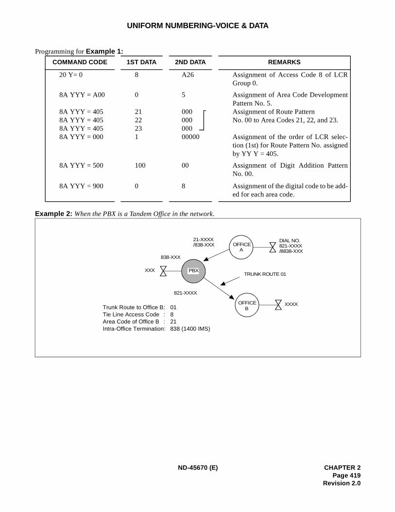
UNIFORM NUMBERING-VOICE & DATA
Programming for Example 1:
Example 2: When the PBX is a Tandem Office in the network.
COMMAND CODE 1ST DATA 2ND DATA REMARKS
20 Y= 0 8 A26 Assignment of Access Code 8 of LCRGroup 0.
8A YYY = A00
8A YYY = 405 8A YYY = 405 8A YYY = 405 8A YYY = 000
0
2122231
5
00000000000000
Assignment of Area Code DevelopmentPattern No. 5.Assignment of Route Pattern No. 00 to Area Codes 21, 22, and 23.
Assignment of the order of LCR selec-tion (1st) for Route Pattern No. assignedby YY Y = 405.
8A YYY = 500 100 00 Assignment of Digit Addition PatternNo. 00.
8A YYY = 900 0 8 Assignment of the digital code to be add-ed for each area code.
OFFICEB
OFFICEA
XXXX
PBX
DIAL NO.821-XXXX/8838-XXX
TRUNK ROUTE 01
21-XXXX/838-XXX
821-XXXX
XXX
838-XXX
Trunk Route to Office B: 01Tie Line Access Code : 8Area Code of Office B : 21Intra-Office Termination: 838 (1400 IMS)
ND-45670 (E) CHAPTER 2Page 419
Revision 2.0
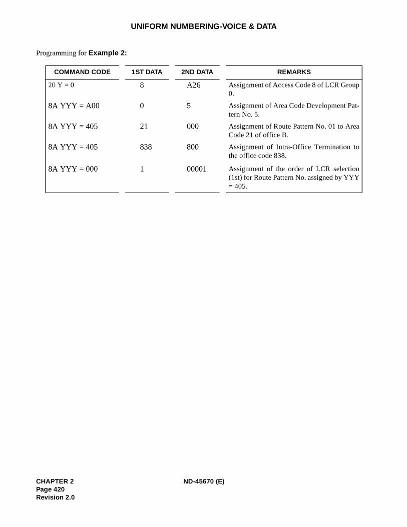
UNIFORM NUMBERING-VOICE & DATA
Programming for Example 2:
COMMAND CODE 1ST DATA 2ND DATA REMARKS
20 Y = 0 8 A26 Assignment of Access Code 8 of LCR Group0.
8A YYY = A00 0 5 Assignment of Area Code Development Pat-tern No. 5.
8A YYY = 405 21 000 Assignment of Route Pattern No. 01 to AreaCode 21 of office B.
8A YYY = 405 838 800 Assignment of Intra-Office Termination tothe office code 838.
8A YYY = 000 1 00001 Assignment of the order of LCR selection(1st) for Route Pattern No. assigned by YYY= 405.
CHAPTER 2 ND-45670 (E)Page 420Revision 2.0
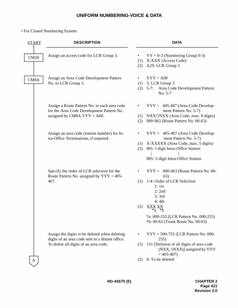
UNIFORM NUMBERING-VOICE & DATA
• For Closed Numbering System
DESCRIPTION DATA
Assign an access code for LCR Group 3. • YY = 0-3 (Numbering Group 0-3) (1) X-XXX (Access Code)(2) A29: LCR Group 3
Assign an Area Code Development Pattern No. to LCR Group 3.
• YYY = A00(1) 3: LCR Group 3 (2) 5-7: Area Code Development Pattern
No. 5-7
Assign a Route Pattern No. to each area code for the Area Code Development Pattern No. assigned by CM8A YYY = A00.
• YYY = 405-407 (Area Code Develop-ment Pattern No. 5-7)
(1) NXX/1NXX (Area Code, max. 8 digits) (2) 000-063 (Route Pattern No. 00-63)
Assign an area code (station number) for In-tra-Office Terminations, if required.
• YYY = 405-407 (Area Code Develop-ment Pattern No. 5-7)
(1) X-XXXXX (Area Code, max. 5 digits)(2) 801: l-digit Intra-Office Station
805: 5-digit Intra-Office Station
Specify the order of LCR selection for the Route Pattern No. assigned by YYY = 405-407.
• YYY = 000-063 (Route Pattern No. 00-63)
(1) 1-4: Order of LCR Selection1: 1st2: 2nd3: 3rd4: 4th
(2) XXX XX
*a: 000-255 (LCR Pattern No. 000-255)*b: 00-63 (Trunk Route No. 00-63)
Assign the digits to be deleted when deleting digits of an area code sent to a distant office. To delete all digits of an area code:
• YYY = 500-755 (LCR Pattern No. 000-255)
(1) 151 [Deletion of all digits of area code (NXX, 1NXX)] assigned by YYY = 405-407)
(2) 0: To be deleted A
START
CM8A
CM20
| |
*b*a
ND-45670 (E) CHAPTER 2Page 421
Revision 2.0
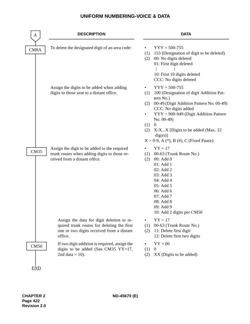
UNIFORM NUMBERING-VOICE & DATA
DESCRIPTION DATA
To delete the designated digit of an area code: • YYY = 500-755(1) 153 (Designation of digit to be deleted) (2) 00: No digits deleted
01: First digit deleted
10: First 10 digits deleted CCC: No digits deleted
Assign the digits to be added when adding digits to those sent to a distant office.
• YYY = 500-755(1) 100 (Designation of digit Addition Pat-
tern No.)(2) 00-49 (Digit Addition Pattern No. 00-49)
CCC: No digits added • YYY = 900-949 (Digit Addition Pattern
No. 00-49) (1) 0 (2) X-X...X [Digits to be added (Max. 32
digits)] X = 0-9, A (*), B (#), C (Fixed Pause)
Assign the digit to be added to the required trunk routes when adding digits to those re-ceived from a distant office.
• YY = 17(1) 00-63 (Trunk Route No.)(2) 00: Add 0
01: Add 102: Add 203: Add 304: Add 405: Add 506: Add 607: Add 708: Add 809: Add 910: Add 2 digits per CM50
Assign the data for digit deletion to re-quired trunk routes for deleting the firstone or two digits received from a distantoffice.
• YY = 17 (1) 00-63 (Trunk Route No.) (2) 11: Delete first digit
12: Delete first two digits
If two digit addition is required, assign thedigits to be added (See CM35 YY=17,2nd data = 10).
• YY = 00(1) 0 (2) XX (Digits to be added)
A
CM35
CM8A
END
CM50
| |
CHAPTER 2 ND-45670 (E)Page 422Revision 2.0
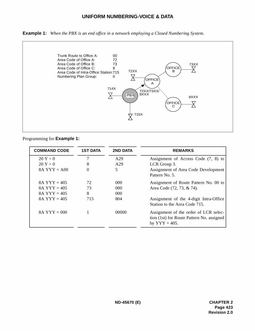
UNIFORM NUMBERING-VOICE & DATA
Example 1: When the PBX is an end office in a network employing a Closed Numbering System.
Programming for Example 1:
COMMAND CODE 1ST DATA 2ND DATA REMARKS
20 Y = 020 Y = 08A YYY = A00
780
A29A295
Assignment of Access Code (7, 8) toLCR Group 3.Assignment of Area Code DevelopmentPattern No. 5.
8A YYY = 405 8A YYY = 405 8A YYY = 405 8A YYY = 405
72738715
000000000804
Assignment of Route Pattern No. 00 toArea Code (72, 73, & 74).
Assignment of the 4-digit Intra-OfficeStation to the Area Code 715.
8A YYY = 000 1 00000 Assignment of the order of LCR selec-tion (1st) for Route Pattern No. assignedby YYY = 405.
73XXOFFICE
B
OFFICEC
OFFICEA
72XX
714X72XX/73XX/8XXX
8XXX
Trunk Route to Office A: Area Code of Office A: Area Code of Office B: Area Code of Office C: Area Code of Intra-Office Station: Numbering Plan Group:
PBX
715X
00727387150
ND-45670 (E) CHAPTER 2Page 423
Revision 2.0
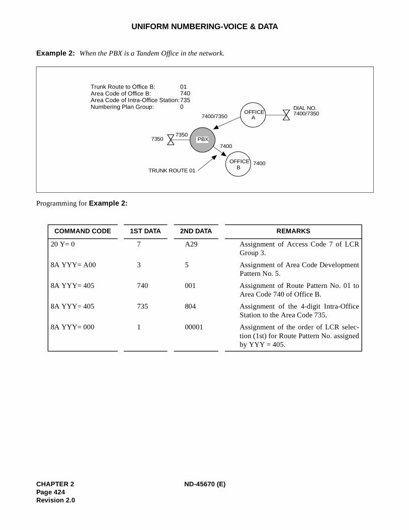
UNIFORM NUMBERING-VOICE & DATA
Example 2: When the PBX is a Tandem Office in the network.
Programming for Example 2:
COMMAND CODE 1ST DATA 2ND DATA REMARKS
20 Y= 0 7 A29 Assignment of Access Code 7 of LCRGroup 3.
8A YYY= A00 3 5 Assignment of Area Code DevelopmentPattern No. 5.
8A YYY= 405 740 001 Assignment of Route Pattern No. 01 toArea Code 740 of Office B.
8A YYY= 405 735 804 Assignment of the 4-digit Intra-OfficeStation to the Area Code 735.
8A YYY= 000 1 00001 Assignment of the order of LCR selec-tion (1st) for Route Pattern No. assignedby YYY = 405.
OFFICEB
OFFICEA
Trunk Route to Office B: Area Code of Office B: Area Code of Intra-Office Station: Numbering Plan Group:
PBX
DIAL NO.7400/7350
TRUNK ROUTE 01
73507350
7400
7400/7350
7400
017407350
CHAPTER 2 ND-45670 (E)Page 424Revision 2.0
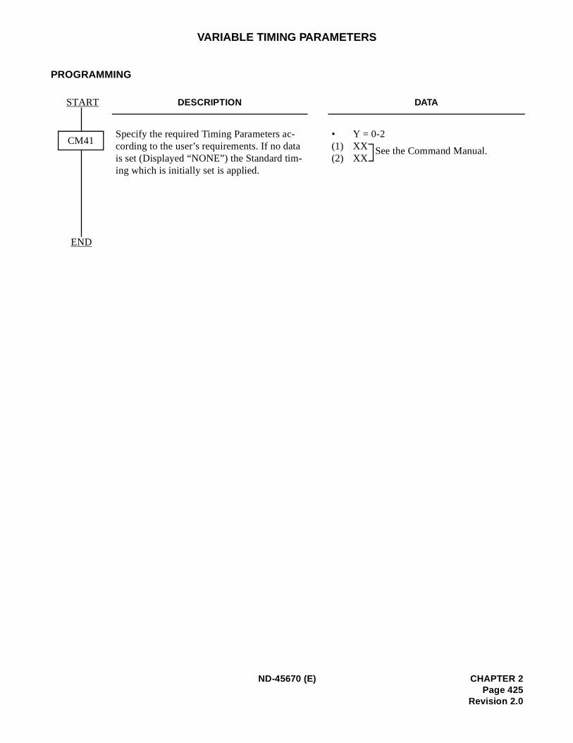
VARIABLE TIMING PARAMETERS
PROGRAMMING
DESCRIPTION DATA
Specify the required Timing Parameters ac-cording to the user’s requirements. If no data is set (Displayed “NONE”) the Standard tim-ing which is initially set is applied.
• Y = 0-2(1) XX (2) XX
START
CM41
END
See the Command Manual.
ND-45670 (E) CHAPTER 2Page 425
Revision 2.0
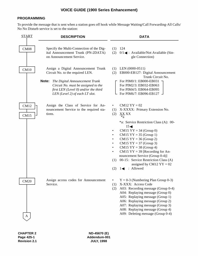
CHAPTER 2 ND-45670 (E)Page 425-1 Addendum-001Revision 2.1 JULY, 1998
VOICE GUIDE (1900 Series Enhancement)
PROGRAMMING
To provide the message that is sent when a station goes off hook while Message Waiting/Call Forwarding-All Calls/No No Disturb service is set to the station:
DESCRIPTION DATA
Specify the Multi-Connection of the Dig-ital Announcement Trunk (PN-2DATA)on Announcement Service.
(1) 124 (2) 0/1 : Available/Not Available (Sin-
gle Connection)
Assign a Digital Announcement TrunkCircuit No. to the required LEN.
Note: The Digital Announcement Trunk Circuit No. must be assigned to the first LEN (Level 0) and/or the third LEN (Level 2) of each LT slot.
(1) LEN (0000-0511) (2) EB000-EB127: Digital Announcement
Trunk Circuit No. For PIM0/1: EB000-EB031 For PIM2/3: EB032-EB063 For PIM4/5: EB064-EB095 For PIM6/7: EB096-EB127
Assign the Class of Service for An-nouncement Service to the required sta-tions.
• CM12 YY = 02(1) X-XXXX: Primary Extension No.(2) XX XX
*a: Service Restriction Class (A): 00-15
• CM15 YY = 34 (Group 0) • CM15 YY = 35 (Group 1) • CM15 YY = 36 (Group 2) • CM15 YY = 37 (Group 3) • CM15 YY = 38 (Group 4) • CM15 YY = 39 [Recording for An-
nouncement Service (Group 0-4)] (1) 00-15: Service Restriction Class (A)
assigned by CM12 YY = 02 (2) 1 : Allowed
Assign access codes for AnnouncementService.
• Y = 0-3 (Numbering Plan Group 0-3) (1) X-XXX: Access Code (2) A03: Recording message (Group 0-4)
A04: Replaying message (Group 0)A05: Replaying message (Group 1)A06: Replaying message (Group 2) A07: Replaying message (Group 3)A08: Replaying message (Group 4)A09: Deleting message (Group 0-4)
CM08
CM10
START
A
CM20
CM12
CM15 *a

ND-45670 (E) CHAPTER 2Addendum-001 Page 425-2
JULY, 1998 Revision 2.1
VOICE GUIDE (1900 Series Enhancement)
Note 1: While both Message Waiting and Call Forwarding-All Calls/Do Not Disturb Service are set to the station,the message assigned by CM49 YY=13 1st data 00 is sent.
Note 2: While Message Reminder (from STA/ATT) Service is set to the station, the message assigned by CM49YY=13 1st data 00 is sent.
Note 3: While Split Call Forwarding-All Calls Service is set to the station, the message assigned by CM49 YY=131st data 03 is sent.
DESCRIPTION DATA
Specify the dial tone, which is sent when a sta-tion goes off hook while the service is set forthe station, as Special Dial Tone.
• Y=2(1) 12 (Dial Tone on Setting Message Wait-
ing)13 (Dial Tone on Setting Call Forward-ing-All Calls)14 (Dial Tone on Setting Do Not Dis-turb)
(2) 0: Special Dial Tone
Validate the data set by CM48 Y=2 first data12, 13, 14.
• YYY=116(1) 00-15: Service Restriction Class A(2) 1 : Valid
Assign the function for each Digital An-nouncement Trunk Circuit.
• YY=00(1) 000-127: Digital Announcement Trunk
Circuit No. assigned by CM10 (EB000-EB127)
(2) 17XX: Voice GuideMessage No. used for this feature (00-63)
Assign the Message sent when the stationgoes off hook.
• YY=13(1) 00 (Message sent when Message Waiting
is set)03 (Message sent when Call Forwarding-All Calls/Do Not Disturb is set)
(2) Message No. (00-63)
END
CM49
CM48
CM15
A
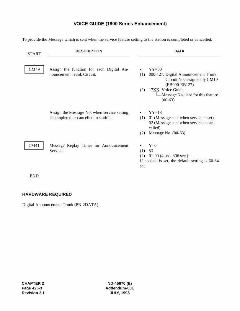
CHAPTER 2 ND-45670 (E)Page 425-3 Addendum-001Revision 2.1 JULY, 1998
VOICE GUIDE (1900 Series Enhancement)
To provide the Message which is sent when the service feature setting to the station is completed or cancelled:
HARDWARE REQUIRED
Digital Announcement Trunk (PN-2DATA)
DESCRIPTION DATA
Assign the function for each Digital An-nouncement Trunk Circuit.
• YY=00(1) 000-127: Digital Announcement Trunk
Circuit No. assigned by CM10 (EB000-EB127)
(2) 17XX: Voice GuideMessage No. used for this feature (00-63)
Assign the Message No. when service settingis completed or cancelled to station.
• YY=13(1) 01 (Message sent when service is set)
02 (Message sent when service is can-celled)
(2) Message No. (00-63)
Message Replay Timer for AnnouncementService.
• Y=0(1) 53(2) 01-99 (4 sec.-396 sec.)If no data is set, the default setting is 60-64sec.
START
END
CM49
CM41

ND-45670 (E) CHAPTER 2Addendum-001 Page 425-4
JULY, 1998 Revision 2.1
This page is for your notes.
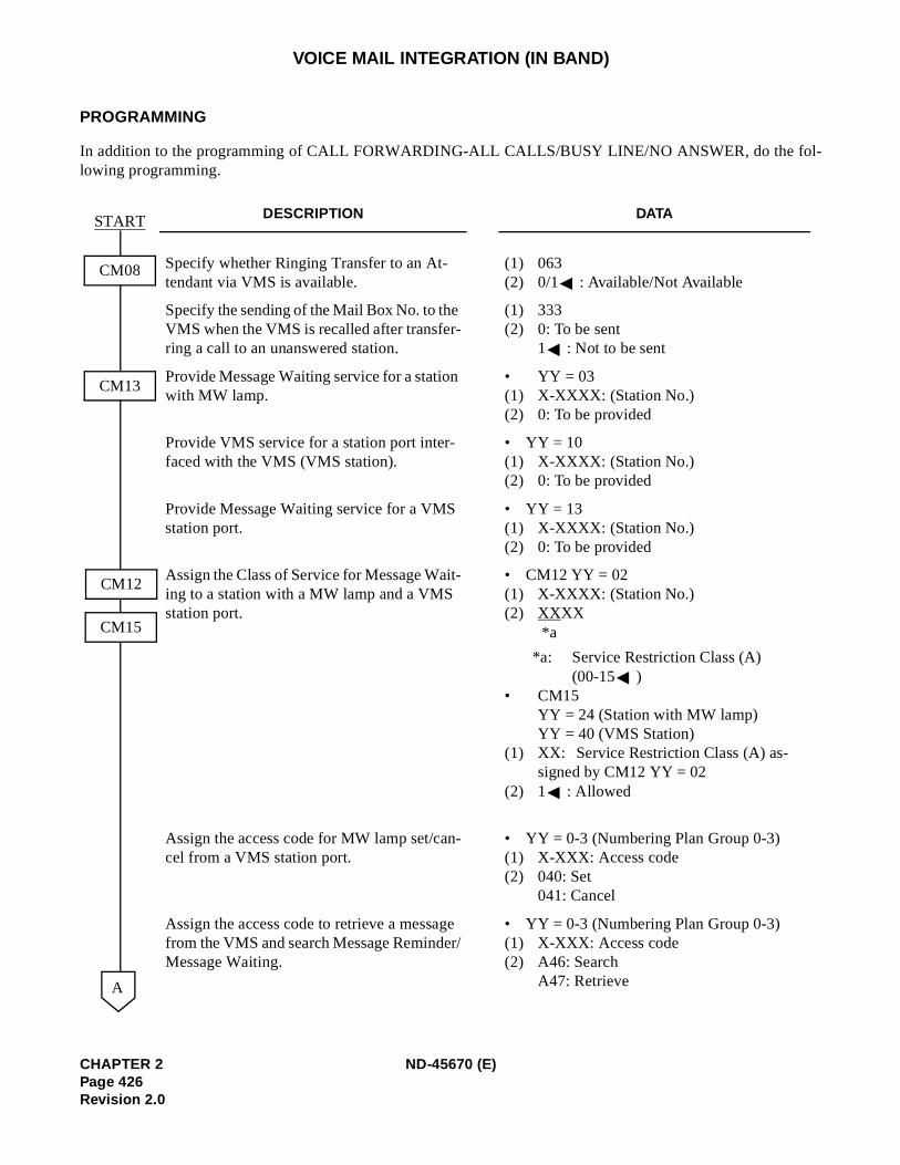
l-
VOICE MAIL INTEGRATION (IN BAND)
PROGRAMMING
In addition to the programming of CALL FORWARDING-ALL CALLS/BUSY LINE/NO ANSWER, do the folowing programming.
DESCRIPTION DATA
Specify whether Ringing Transfer to an At-tendant via VMS is available.
(1) 063(2) 0/1 : Available/Not Available
Specify the sending of the Mail Box No. to the VMS when the VMS is recalled after transfer-ring a call to an unanswered station.
(1) 333(2) 0: To be sent
1 : Not to be sent
Provide Message Waiting service for a station with MW lamp.
• YY = 03(1) X-XXXX: (Station No.)(2) 0: To be provided
Provide VMS service for a station port inter-faced with the VMS (VMS station).
• YY = 10(1) X-XXXX: (Station No.)(2) 0: To be provided
Provide Message Waiting service for a VMS station port.
• YY = 13(1) X-XXXX: (Station No.)(2) 0: To be provided
Assign the Class of Service for Message Wait-ing to a station with a MW lamp and a VMS station port.
• CM12 YY = 02(1) X-XXXX: (Station No.)(2) XXXX
*a
*a: Service Restriction Class (A)(00-15 )
• CM15YY = 24 (Station with MW lamp)YY = 40 (VMS Station)
(1) XX: Service Restriction Class (A) as-signed by CM12 YY = 02
(2) 1 : Allowed
Assign the access code for MW lamp set/can-cel from a VMS station port.
• YY = 0-3 (Numbering Plan Group 0-3)(1) X-XXX: Access code(2) 040: Set
041: Cancel
Assign the access code to retrieve a message from the VMS and search Message Reminder/Message Waiting.
• YY = 0-3 (Numbering Plan Group 0-3)(1) X-XXX: Access code(2) A46: Search
A47: Retrieve
START
CM08
CM13
CM12
CM15
A
CHAPTER 2 ND-45670 (E)Page 426Revision 2.0
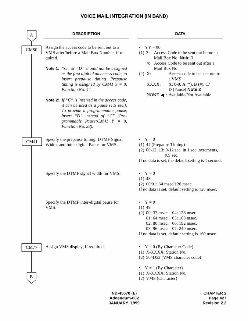
VOICE MAIL INTEGRATION (IN BAND)
DESCRIPTION DATA
Assign the access code to be sent out to a VMS after/before a Mail Box Number, if re-quired.
Note 1: “C” or “D” should not be assignedas the first digit of an access code, toinsert prepause timing. Prepausetiming is assigned by CM41 Y = 0,Function No. 44.
Note 2: If “C” is inserted in the access code,it can be used as a pause (1.5 sec.).To provide a programmable pause,insert “D” instead of “C” (Pro-grammable Pause:CM41 Y = 0,Function No. 38).
• YY = 00(1) 3: Access Code to be sent out before a
Mail Box No. Note 1 4: Access Code to be sent out after a
Mail Box No. (2) X: Access code to be sent out to
a VMSXXXX: X: 0-9, A (*), B (#), C/
D (Pause) Note 2NONE : Available/Not Available
Specify the prepause timing, DTMF Signal Width, and Inter-digital Pause for VMS.
• Y = 0(1) 44 (Prepause Timing)(2) 00-12, 13: 0-12 sec. in 1 sec increments,
0.5 sec.If no data is set, the default setting is 1 second.
Specify the DTMF signal width for VMS. • Y = 0(1) 48(2) 00/01: 64 msec/128 msecIf no data is set, default setting is 128 msec.
Specify the DTMF inter-digital pause for VMS.
• Y = 0(1) 49(2) 00: 32 msec. 04: 128 msec
01: 64 msec. 05: 160 msec.02: 80 msec. 06: 192 msec.03: 96 msec. 07: 240 msec.
If no data is set, default setting is 160 msec.
Assign VMS display, if required. • Y = 0 (By Character Code)(1) X-XXXX: Station No.(2) 564D53 (VMS character code)
• Y = 1 (By Character)(1) X-XXXX: Station No.(2) VMS (Character)
CM50
CM77
CM41
B
A
ND-45670 (E) CHAPTER 2Addendum-002 Page 427JANUARY, 1999 Revision 2.2
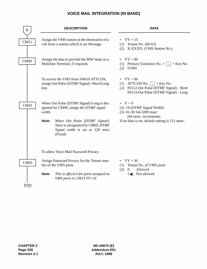
CHAPTER 2 ND-45670 (E)Page 428 Addendum-001Revision 2.1 JULY, 1998
VOICE MAIL INTEGRATION (IN BAND)
DESCRIPTION DATA
Assign the VMS station as the destination of a call from a station which is set Message.
• YY = 15(1) Tenant No. (00-63)(2) X-XXXX: (VMS Station No.)
Assign the data to provide the MW lamp on a Multiline Terminal, if required.
• YY = 00(1) Primary Extension No. + + Key No. (2) F1005
To access the VMS from SN610 ATTCON, assign Out Pulse (DTMF Signal) -Short/Long key.
• YY = 00(1) ATTCON No. + Key No.(2) F6112:Out Pulse (DTMF Signal) - Short
F6113:Out Pulse (DTMF Signal) - Long
When Out Pulse (DTMF Signal)-Long is des-ignated by CM90, assign the DTMF signal width.
Note: When Out Pulse (DTMF Signal)-Short is designated by CM90, DTMFSignal width is set to 128 msec(Fixed).
To allow Voice Mail Password Privacy
Assign Password Privacy for the Tenant num-ber of the VMS ports.
Note: This is effective for ports assigned asVMS ports in CM13 YY=10
• Y = 0(1) 14 (DTMF Signal Width)(2) 01-50: 64-3200 msec
(64 msec. increments)If no data is set, default setting is 512 msec.
• YY = 30(1) Tenant No. of VMS ports(2) 0: Allowed
1 : Not allowed
CM51
CM41
B
CM90
END
CM65
,
,
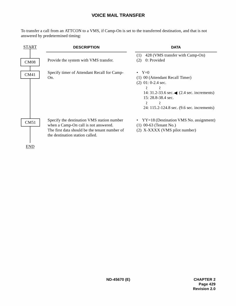
)
)
VOICE MAIL TRANSFER
To transfer a call from an ATTCON to a VMS, if Camp-On is set to the transferred destination, and that is not answered by predetermined timing:
DESCRIPTION DATA
Provide the system with VMS transfer.(1) 428 (VMS transfer with Camp-On)(2) 0: Provided
Specify timer of Attendant Recall for Camp-On.
• Y=0(1) 00 (Attendant Recall Timer)(2) 01: 0-2.4 sec.
14: 31.2-33.6 sec. (2.4 sec. increments15: 28.8-38.4 sec.
24: 115.2-124.8 sec. (9.6 sec. increments)
Specify the destination VMS station number when a Camp-On call is not answered. The first data should be the tenant number of the destination station called.
• YY=18 (Destination VMS No. assignment(1) 00-63 (Tenant No.)(2) X-XXXX (VMS pilot number)
START
CM08
CM41
CM51
END
~ ~
~ ~
ND-45670 (E) CHAPTER 2Page 429
Revision 2.0
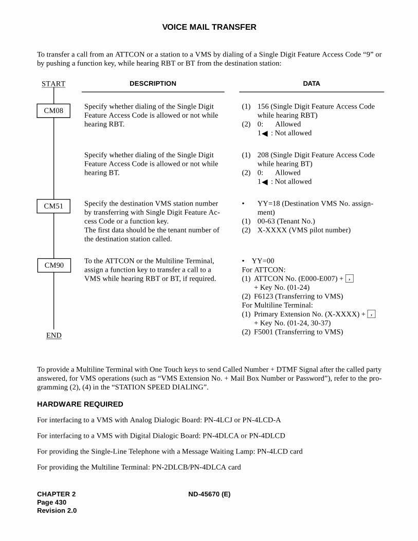
“9” or
partye pro-
VOICE MAIL TRANSFER
To transfer a call from an ATTCON or a station to a VMS by dialing of a Single Digit Feature Access Code by pushing a function key, while hearing RBT or BT from the destination station:
To provide a Multiline Terminal with One Touch keys to send Called Number + DTMF Signal after the calledanswered, for VMS operations (such as “VMS Extension No. + Mail Box Number or Password”), refer to thgramming (2), (4) in the “STATION SPEED DIALING”.
HARDWARE REQUIRED
For interfacing to a VMS with Analog Dialogic Board: PN-4LCJ or PN-4LCD-A
For interfacing to a VMS with Digital Dialogic Board: PN-4DLCA or PN-4DLCD
For providing the Single-Line Telephone with a Message Waiting Lamp: PN-4LCD card
For providing the Multiline Terminal: PN-2DLCB/PN-4DLCA card
DESCRIPTION DATA
Specify whether dialing of the Single Digit Feature Access Code is allowed or not while hearing RBT.
(1) 156 (Single Digit Feature Access Code while hearing RBT)
(2) 0: Allowed 1 : Not allowed
Specify whether dialing of the Single Digit Feature Access Code is allowed or not while hearing BT.
(1) 208 (Single Digit Feature Access Code while hearing BT)
(2) 0: Allowed 1 : Not allowed
Specify the destination VMS station number by transferring with Single Digit Feature Ac-cess Code or a function key. The first data should be the tenant number of the destination station called.
• YY=18 (Destination VMS No. assign-ment)
(1) 00-63 (Tenant No.)(2) X-XXXX (VMS pilot number)
To the ATTCON or the Multiline Terminal, assign a function key to transfer a call to a VMS while hearing RBT or BT, if required.
• YY=00For ATTCON:(1) ATTCON No. (E000-E007) +
+ Key No. (01-24)(2) F6123 (Transferring to VMS)For Multiline Terminal:(1) Primary Extension No. (X-XXXX) +
+ Key No. (01-24, 30-37)(2) F5001 (Transferring to VMS)
START
CM08
CM51
CM90
END
,
,
CHAPTER 2 ND-45670 (E)Page 430Revision 2.0
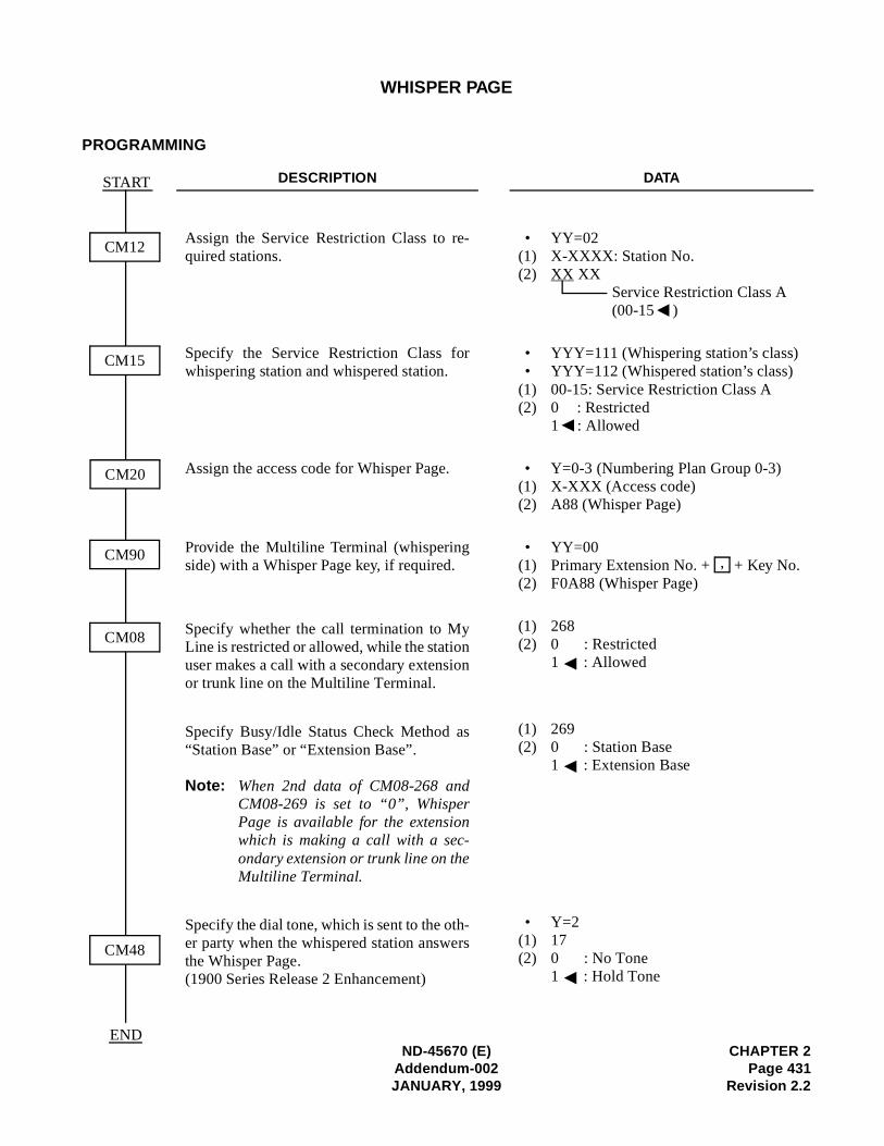
)
WHISPER PAGE
PROGRAMMING
DESCRIPTION DATA
Assign the Service Restriction Class to re-quired stations.
• YY=02(1) X-XXXX: Station No.(2) XX XX
Service Restriction Class A(00-15 )
Specify the Service Restriction Class forwhispering station and whispered station.
• YYY=111 (Whispering station’s class)• YYY=112 (Whispered station’s class)
(1) 00-15: Service Restriction Class A(2) 0 : Restricted
1 : Allowed
Assign the access code for Whisper Page. • Y=0-3 (Numbering Plan Group 0-3(1) X-XXX (Access code)(2) A88 (Whisper Page)
Provide the Multiline Terminal (whisperingside) with a Whisper Page key, if required.
• YY=00(1) Primary Extension No. + + Key No.(2) F0A88 (Whisper Page)
Specify whether the call termination to MyLine is restricted or allowed, while the stationuser makes a call with a secondary extensionor trunk line on the Multiline Terminal.
(1) 268 (2) 0 : Restricted
1 : Allowed
Specify Busy/Idle Status Check Method as“Station Base” or “Extension Base”.
Note: When 2nd data of CM08-268 andCM08-269 is set to “0”, WhisperPage is available for the extensionwhich is making a call with a sec-ondary extension or trunk line on theMultiline Terminal.
(1) 269 (2) 0 : Station Base
1 : Extension Base
Specify the dial tone, which is sent to the oth-er party when the whispered station answersthe Whisper Page.(1900 Series Release 2 Enhancement)
• Y=2(1) 17 (2) 0 : No Tone
1 : Hold Tone
CM12
CM15
CM20
START
CM90
CM08
CM48
,
ND-45670 (E) CHAPTER 2Addendum-002 Page 431JANUARY, 1999 Revision 2.2
END
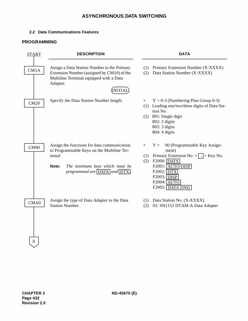
ASYNCHRONOUS DATA SWITCHING
2.2 Data Communications Features
PROGRAMMING
DESCRIPTION DATA
Assign a Data Station Number to the Primary Extension Number (assigned by CM10) of the Multiline Terminal equipped with a Data Adapter.
(1) Primary Extension Number (X-XXXX)(2) Data Station Number (X-XXXX)
Specify the Data Station Number length. • Y = 0-3 (Numbering Plan Group 0-3)(1) Leading one/two/three digits of Data Sta-
tion No.(2) 801: Single digit
802: 2 digits803: 3 digits804: 4 digits
Assign the functions for data communication to Programmable Keys on the Multiline Ter-minal.
Note: The minimum keys which must beprogrammed are and .
• Y = 00 (Programmable Key Assign-ment)
(1) Primary Extension No. + + Key No.(2) F2000:
F2001: F2002: F2003: F2004: F2005:
Assign the type of Data Adapter to the Data Station Number.
(1) Data Station No. (X-XXXX)(2) 02: SN1152 DTAM-A Data Adapter
CM1A
START
CM20
A
CM90
CMA0
INITIAL
DATA DTX
,
DATAAUTO/DISPDTXDISPAUTODATA DND
CHAPTER 2 ND-45670 (E)Page 432Revision 2.0
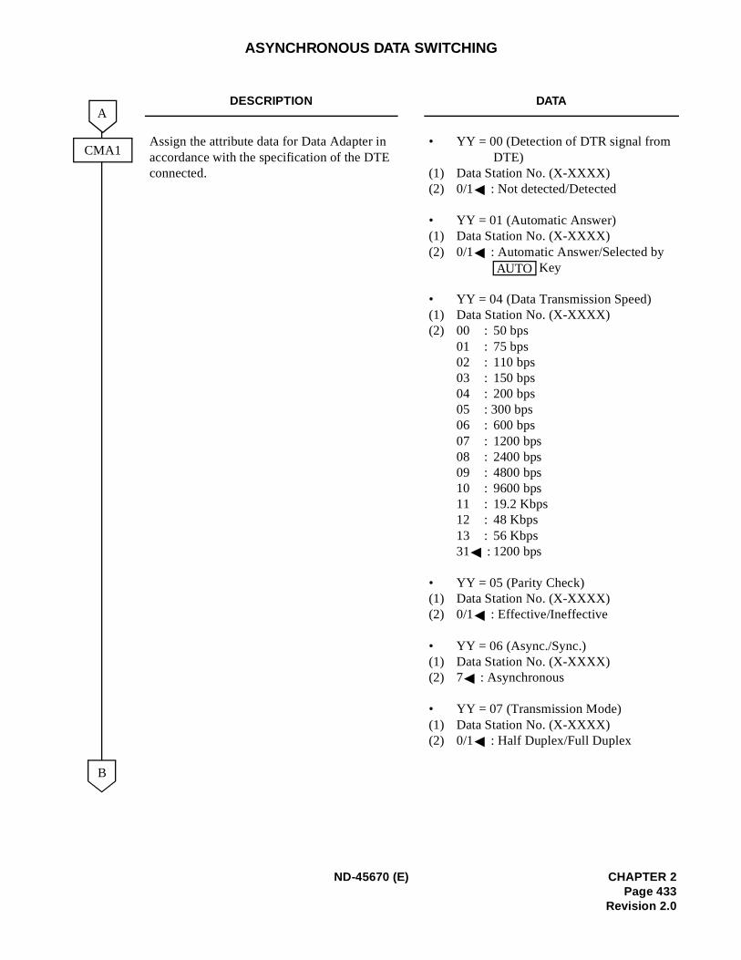
ASYNCHRONOUS DATA SWITCHING
DESCRIPTION DATA
Assign the attribute data for Data Adapter in accordance with the specification of the DTE connected.
• YY = 00 (Detection of DTR signal from DTE)
(1) Data Station No. (X-XXXX)(2) 0/1 : Not detected/Detected
• YY = 01 (Automatic Answer)(1) Data Station No. (X-XXXX)(2) 0/1 : Automatic Answer/Selected by
Key
• YY = 04 (Data Transmission Speed)(1) Data Station No. (X-XXXX)(2) 00 : 50 bps
01 : 75 bps02 : 110 bps03 : 150 bps04 : 200 bps05 : 300 bps06 : 600 bps07 : 1200 bps08 : 2400 bps09 : 4800 bps10 : 9600 bps11 : 19.2 Kbps12 : 48 Kbps13 : 56 Kbps31 : 1200 bps
• YY = 05 (Parity Check)(1) Data Station No. (X-XXXX)(2) 0/1 : Effective/Ineffective
• YY = 06 (Async./Sync.)(1) Data Station No. (X-XXXX)(2) 7 : Asynchronous
• YY = 07 (Transmission Mode)(1) Data Station No. (X-XXXX)(2) 0/1 : Half Duplex/Full Duplex
B
A
CMA1
AUTO
ND-45670 (E) CHAPTER 2Page 433
Revision 2.0
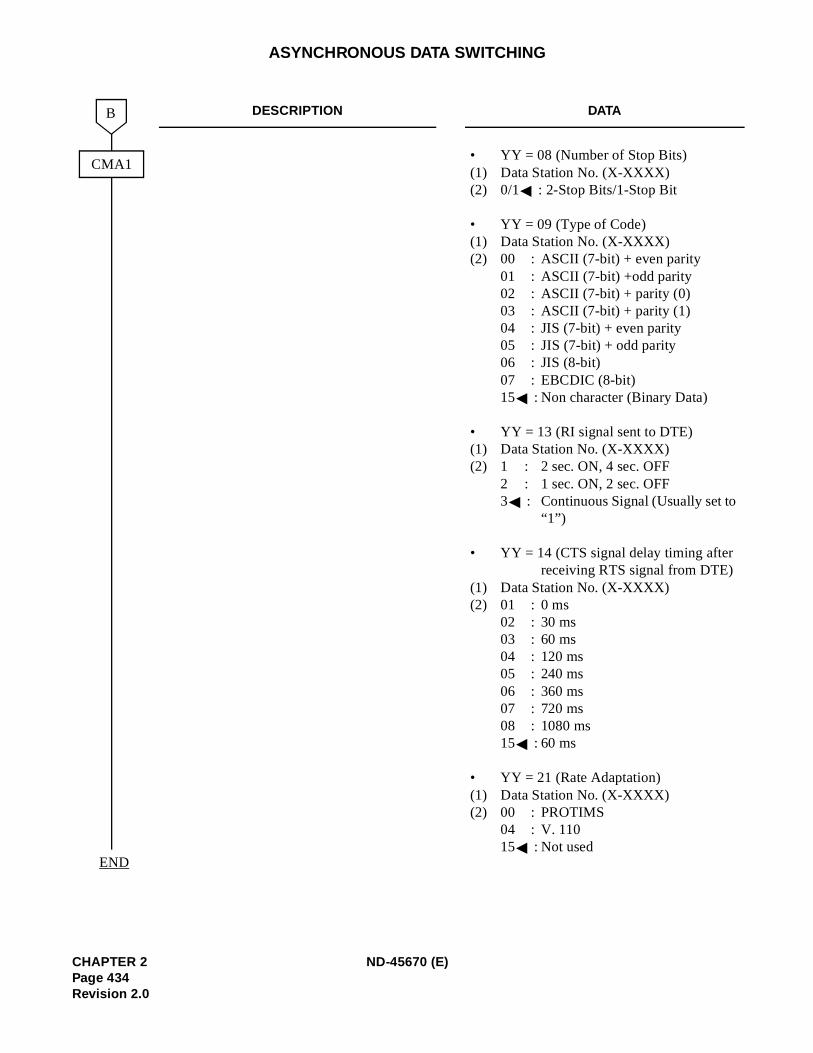
ASYNCHRONOUS DATA SWITCHING
DESCRIPTION DATA
• YY = 08 (Number of Stop Bits)(1) Data Station No. (X-XXXX)(2) 0/1 : 2-Stop Bits/1-Stop Bit
• YY = 09 (Type of Code)(1) Data Station No. (X-XXXX)(2) 00 : ASCII (7-bit) + even parity
01 : ASCII (7-bit) +odd parity02 : ASCII (7-bit) + parity (0)03 : ASCII (7-bit) + parity (1)04 : JIS (7-bit) + even parity05 : JIS (7-bit) + odd parity06 : JIS (8-bit)07 : EBCDIC (8-bit)15 : Non character (Binary Data)
• YY = 13 (RI signal sent to DTE)(1) Data Station No. (X-XXXX)(2) 1 : 2 sec. ON, 4 sec. OFF
2 : 1 sec. ON, 2 sec. OFF3 : Continuous Signal (Usually set to
“1”)
• YY = 14 (CTS signal delay timing after receiving RTS signal from DTE)
(1) Data Station No. (X-XXXX)(2) 01 : 0 ms
02 : 30 ms03 : 60 ms04 : 120 ms05 : 240 ms06 : 360 ms07 : 720 ms08 : 1080 ms15 : 60 ms
• YY = 21 (Rate Adaptation)(1) Data Station No. (X-XXXX)(2) 00 : PROTIMS
04 : V. 11015 : Not used
CMA1
B
END
CHAPTER 2 ND-45670 (E)Page 434Revision 2.0

ASYNCHRONOUS DATA SWITCHING
HARDWARE REQUIRED
SN1152 DTAM-A Data Adapter
ETJ-8-1/ETJ-16DC-1/ETJ-16DD-1/ETJ-24DS-1 and PN-2DLCB/4DLCA card
DTE
ND-45670 (E) CHAPTER 2Page 435
Revision 2.0
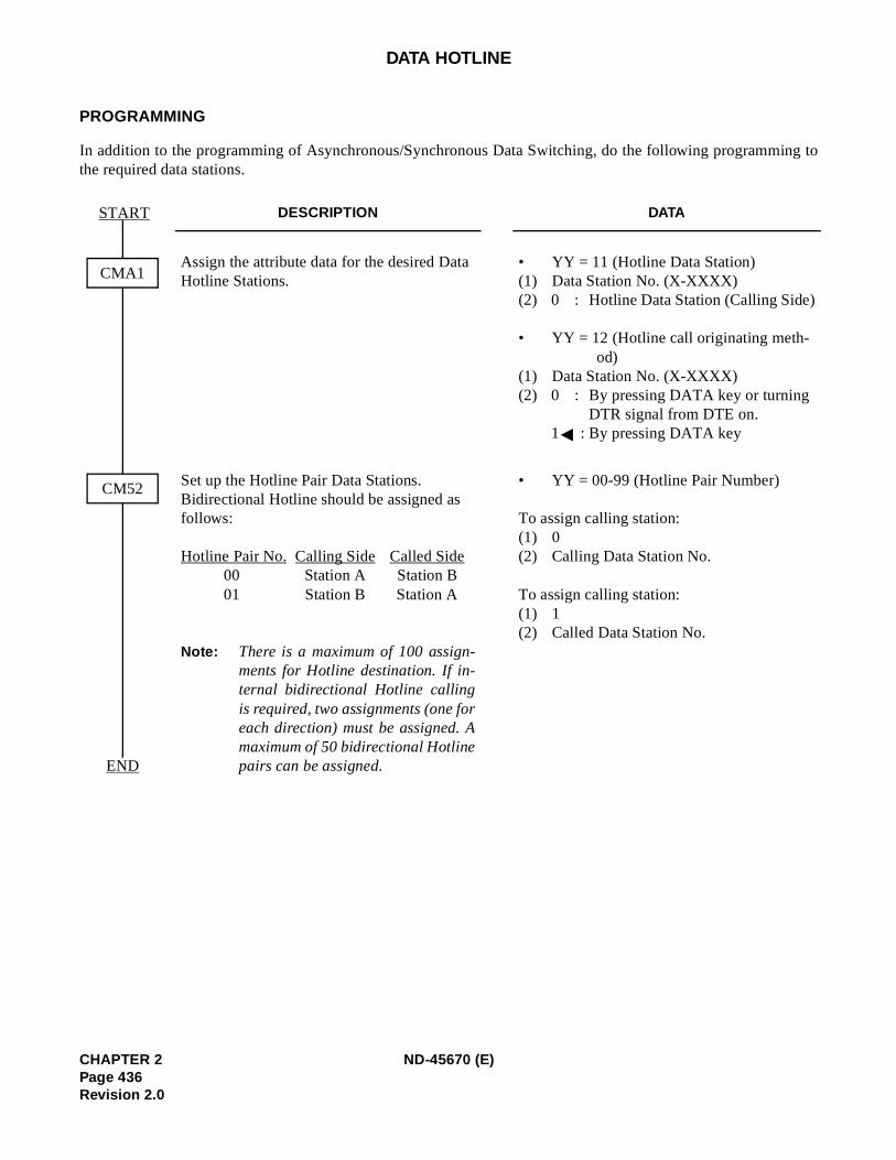
ing to
DATA HOTLINE
PROGRAMMING
In addition to the programming of Asynchronous/Synchronous Data Switching, do the following programmthe required data stations.
DESCRIPTION DATA
Assign the attribute data for the desired Data Hotline Stations.
• YY = 11 (Hotline Data Station)(1) Data Station No. (X-XXXX)(2) 0 : Hotline Data Station (Calling Side)
• YY = 12 (Hotline call originating meth-od)
(1) Data Station No. (X-XXXX)(2) 0 : By pressing DATA key or turning
DTR signal from DTE on.1 : By pressing DATA key
Set up the Hotline Pair Data Stations.Bidirectional Hotline should be assigned as follows:
Hotline Pair No. Calling Side Called Side00 Station A Station B01 Station B Station A
Note: There is a maximum of 100 assign-ments for Hotline destination. If in-ternal bidirectional Hotline callingis required, two assignments (one foreach direction) must be assigned. Amaximum of 50 bidirectional Hotlinepairs can be assigned.
• YY = 00-99 (Hotline Pair Number)
To assign calling station:(1) 0(2) Calling Data Station No.
To assign calling station:(1) 1(2) Called Data Station No.
CMA1
END
START
CM52
CHAPTER 2 ND-45670 (E)Page 436Revision 2.0
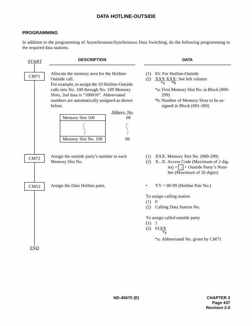
ing to
DATA HOTLINE-OUTSIDE
PROGRAMMING
In addition to the programming of Asynchronous/Synchronous Data Switching, do the following programmthe required data stations.
DESCRIPTION DATA
Allocate the memory area for the Hotline-Outside call.For example, to assign the 10 Hotline-Outside calls into No. 100 through No. 109 Memory Slots, 2nd data is “100010”. Abbreviated numbers are automatically assigned as shown below.
(1) 65: For Hotline-Outside(2) XXX XXX : See left column
*a: First Memory Slot No. in Block (000-299)
*b: Number of Memory Slots to be as-signed in Block (001-300)
Assign the outside party’s number to each Memory Slot No.
(1) XXX: Memory Slot No. (000-299)(2) X...X: Access Code (Maximum of 2 dig-
its) + + Outside Party’s Num-ber (Maximum of 26 digits)
Assign the Data Hotline pairs. • YY = 00-99 (Hotline Pair No.)
To assign calling station(1) 0(2) Calling Data Station No.
To assign called outside party(1) 1(2) 01XX
*a: Abbreviated No. given by CM71
CM71
END
START
CM72
CM52
Abbrev. No.Memory Slot 100 00
Memory Slot No. 109 09
*b*a
,
*a
ND-45670 (E) CHAPTER 2Page 437
Revision 2.0
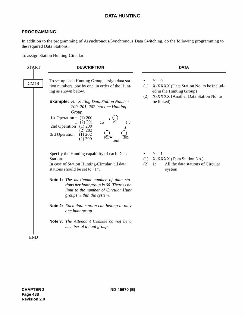
ing to
DATA HUNTING
PROGRAMMING
In addition to the programming of Asynchronous/Synchronous Data Switching, do the following programmthe required Data Stations.
To assign Station Hunting-Circular:
DESCRIPTION DATA
To set up each Hunting Group, assign data sta-tion numbers, one by one, in order of the Hunt-ing as shown below.
Example: For Setting Data Station Number 200, 201, 202 into one Hunting Group.
• Y = 0(1) X-XXXX (Data Station No. to be includ-
ed in the Hunting Group)(2) X-XXXX (Another Data Station No. to
be linked)
Specify the Hunting capability of each Data Station.In case of Station Hunting-Circular, all data stations should be set to “1”.
Note 1: The maximum number of data sta-tions per hunt group is 60. There is nolimit to the number of Circular Huntgroups within the system.
Note 2: Each data station can belong to onlyone hunt group.
Note 3: The Attendant Console cannot be amember of a hunt group.
• Y = 1(1) X-XXXX (Data Station No.)(2) 1: All the data stations of Circular
system
CM18
START
END
3rd1st
2nd
200
202201
1st Operation (1) 200(2) 201
2nd Operation (1) 200(2) 202
3rd Operation (1) 202(2) 200
CHAPTER 2 ND-45670 (E)Page 438Revision 2.0
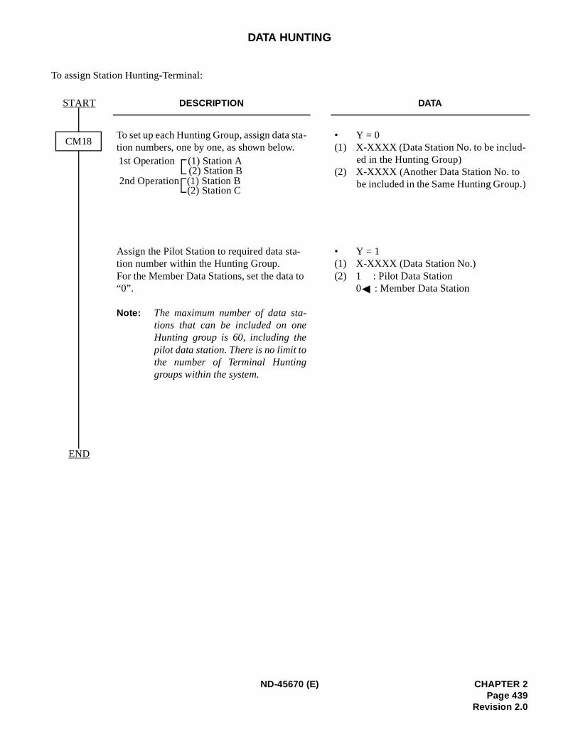
)
DATA HUNTING
To assign Station Hunting-Terminal:
DESCRIPTION DATA
To set up each Hunting Group, assign data sta-tion numbers, one by one, as shown below.
• Y = 0(1) X-XXXX (Data Station No. to be includ-
ed in the Hunting Group)(2) X-XXXX (Another Data Station No. to
be included in the Same Hunting Group.
Assign the Pilot Station to required data sta-tion number within the Hunting Group.For the Member Data Stations, set the data to “0”.
Note: The maximum number of data sta-tions that can be included on oneHunting group is 60, including thepilot data station. There is no limit tothe number of Terminal Huntinggroups within the system.
• Y = 1(1) X-XXXX (Data Station No.)(2) 1 : Pilot Data Station
0 : Member Data Station
CM18
START
END
1st Operation (1) Station A(2) Station B
2nd Operation (1) Station B(2) Station C
ND-45670 (E) CHAPTER 2Page 439
Revision 2.0
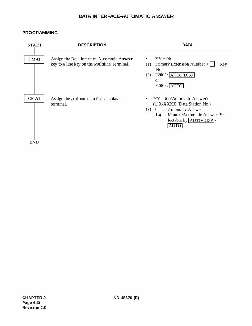
DATA INTERFACE-AUTOMATIC ANSWER
PROGRAMMING
DESCRIPTION DATA
Assign the Data Interface-Automatic Answer key to a line key on the Multiline Terminal.
• YY = 00 (1) Primary Extension Number + + Key
No. (2) F2001:
orF2003:
Assign the attribute data for each data terminal.
• YY = 01 (Automatic Answer)(1)X-XXXX (Data Station No.)
(2) 0 : Automatic Answer1 : Manual/Automatic Answer (Se-
lectable by / )
CM90
START
END
CMA1
,
AUTO/DISP
AUTO
AUTO/DISPAUTO
CHAPTER 2 ND-45670 (E)Page 440Revision 2.0
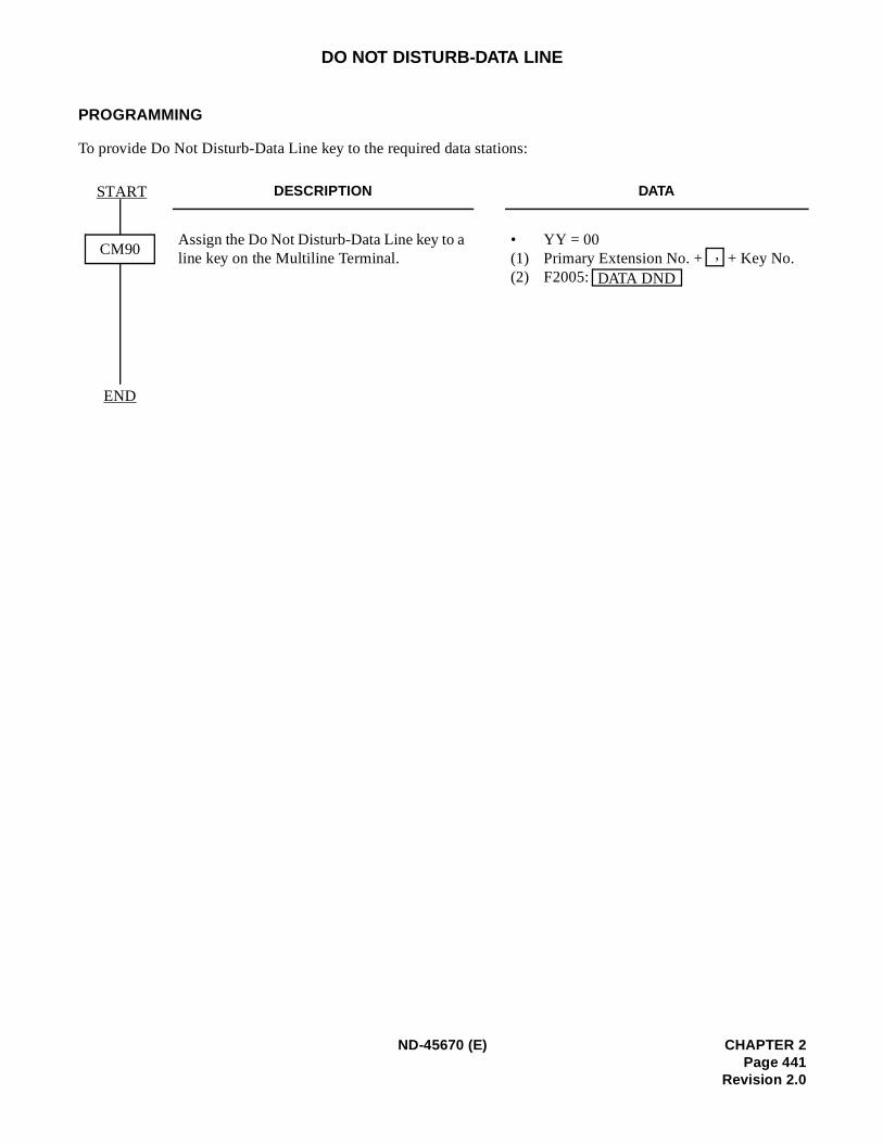
DO NOT DISTURB-DATA LINE
PROGRAMMING
To provide Do Not Disturb-Data Line key to the required data stations:
DESCRIPTION DATA
Assign the Do Not Disturb-Data Line key to a line key on the Multiline Terminal.
• YY = 00 (1) Primary Extension No. + + Key No. (2) F2005:
CM90
START
END
,
DATA DND
ND-45670 (E) CHAPTER 2Page 441
Revision 2.0
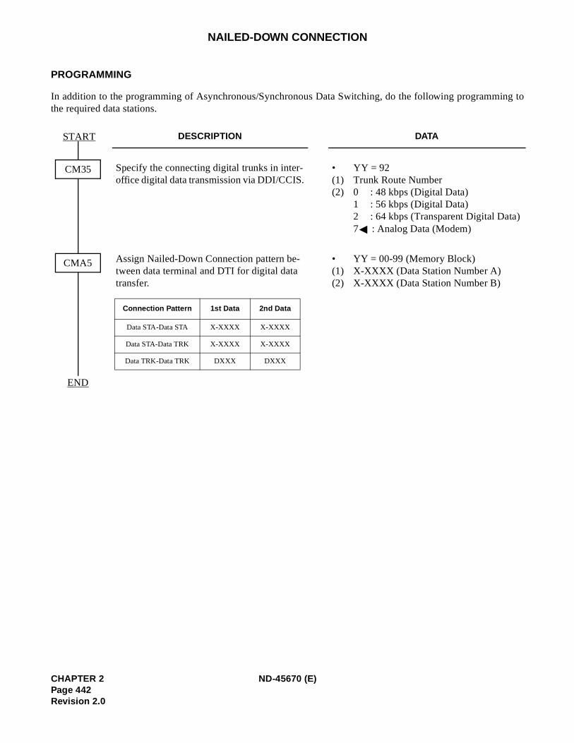
ing to
NAILED-DOWN CONNECTION
PROGRAMMING
In addition to the programming of Asynchronous/Synchronous Data Switching, do the following programmthe required data stations.
DESCRIPTION DATA
Specify the connecting digital trunks in inter-office digital data transmission via DDI/CCIS.
• YY = 92 (1) Trunk Route Number (2) 0 : 48 kbps (Digital Data)
1 : 56 kbps (Digital Data)2 : 64 kbps (Transparent Digital Data)7 : Analog Data (Modem)
Assign Nailed-Down Connection pattern be-tween data terminal and DTI for digital data transfer.
• YY = 00-99 (Memory Block)(1) X-XXXX (Data Station Number A)(2) X-XXXX (Data Station Number B)
CM35
START
END
CMA5
Connection Pattern 1st Data 2nd Data
Data STA-Data STA X-XXXX X-XXXX
Data STA-Data TRK X-XXXX X-XXXX
Data TRK-Data TRK DXXX DXXX
CHAPTER 2 ND-45670 (E)Page 442Revision 2.0
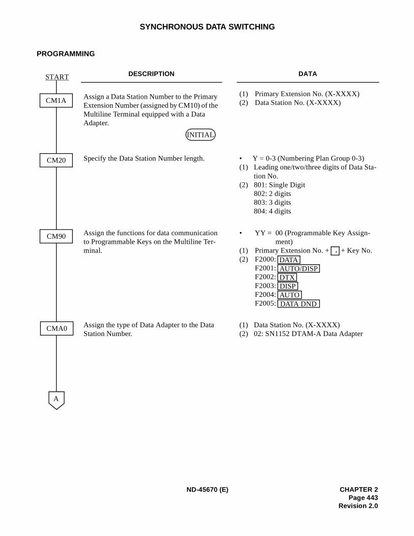
-
SYNCHRONOUS DATA SWITCHING
PROGRAMMING
DESCRIPTION DATA
Assign a Data Station Number to the Primary Extension Number (assigned by CM10) of the Multiline Terminal equipped with a Data Adapter.
(1) Primary Extension No. (X-XXXX)(2) Data Station No. (X-XXXX)
Specify the Data Station Number length. • Y = 0-3 (Numbering Plan Group 0-3)(1) Leading one/two/three digits of Data Sta
tion No.(2) 801: Single Digit
802: 2 digits803: 3 digits804: 4 digits
Assign the functions for data communication to Programmable Keys on the Multiline Ter-minal.
• YY = 00 (Programmable Key Assign-ment)
(1) Primary Extension No. + + Key No.(2) F2000:
F2001: F2002: F2003: F2004: F2005:
Assign the type of Data Adapter to the Data Station Number.
(1) Data Station No. (X-XXXX)(2) 02: SN1152 DTAM-A Data Adapter
CM1A
START
CM20
CM90
A
CMA0
INITIAL
,
DATAAUTO/DISPDTXDISPAUTODATA DND
ND-45670 (E) CHAPTER 2Page 443
Revision 2.0
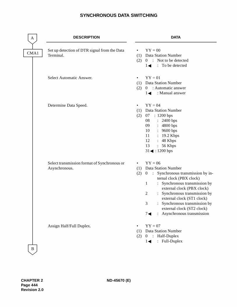
SYNCHRONOUS DATA SWITCHING
DESCRIPTION DATA
Set up detection of DTR signal from the Data Terminal.
• YY = 00 (1) Data Station Number(2) 0 : Not to be detected
1 : To be detected
Select Automatic Answer. • YY = 01 (1) Data Station Number(2) 0 : Automatic answer
1 : Manual answer
Determine Data Speed. • YY = 04(1) Data Station Number(2) 07 : 1200 bps
08 : 2400 bps09 : 4800 bps10 : 9600 bps11 : 19.2 Kbps12 : 48 Kbps13 : 56 Kbps31 : 1200 bps
Select transmission format of Synchronous or Asynchronous.
• YY = 06(1) Data Station Number(2) 0 : Synchronous transmission by in-
ternal clock (PBX clock)1 : Synchronous transmission by
external clock (PBX clock)2 : Synchronous transmission by
external clock (ST1 clock)3 : Synchronous transmission by
external clock (ST2 clock)7 : Asynchronous transmission
Assign Half/Full Duplex. • YY = 07(1) Data Station Number(2) 0 : Half-Duplex
1 : Full-Duplex
B
A
CMA1
CHAPTER 2 ND-45670 (E)Page 444Revision 2.0
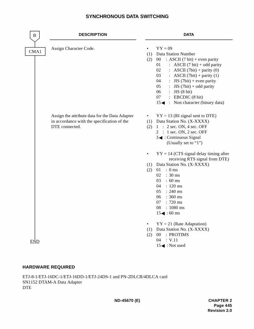
SYNCHRONOUS DATA SWITCHING
HARDWARE REQUIRED
ETJ-8-1/ETJ-16DC-1/ETJ-16DD-1/ETJ-24DS-1 and PN-2DLCB/4DLCA cardSN1152 DTAM-A Data Adapter DTE
DESCRIPTION DATA
Assign Character Code. • YY = 09 (1) Data Station Number(2) 00 : ASCII (7 bit) + even parity
01 : ASCII (7 bit) + odd parity02 : ASCII (7bit) + parity (0)03 : ASCII (7bit) + parity (1)04 : JIS (7bit) + even parity05 : JIS (7bit) + odd parity06 : JIS (8 bit)07 : EBCDIC (8 bit)15 : Non character (binary data)
Assign the attribute data for the Data Adapter in accordance with the specification of the DTE connected.
• YY = 13 (RI signal sent to DTE)(1) Data Station No. (X-XXXX)(2) 1 : 2 sec. ON, 4 sec. OFF
2 : 1 sec. ON, 2 sec. OFF3 : Continuous Signal
(Usually set to “1”)
• YY = 14 (CTS signal delay timing after receiving RTS signal from DTE)
(1) Data Station No. (X-XXXX)(2) 01 : 0 ms
02 : 30 ms03 : 60 ms04 : 120 ms05 : 240 ms06 : 360 ms07 : 720 ms08 : 1080 ms15 : 60 ms
• YY = 21 (Rate Adaptation)(1) Data Station No. (X-XXXX)(2) 00 : PROTIMS
04 : V.1115 : Not used
B
CMA1
END
ND-45670 (E) CHAPTER 2Page 445
Revision 2.0
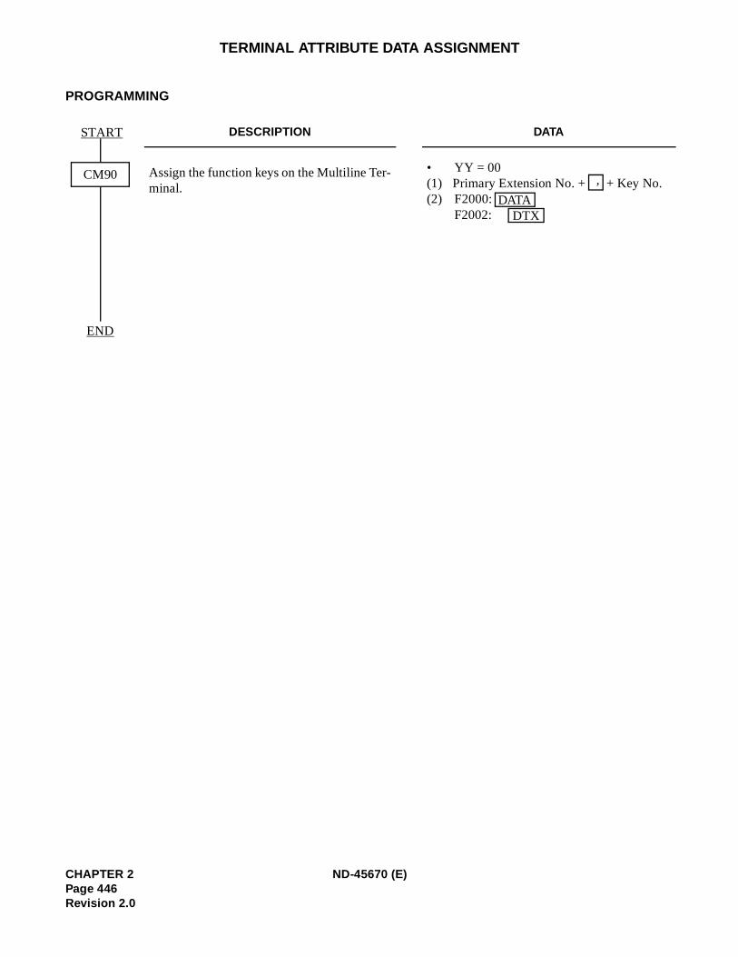
TERMINAL ATTRIBUTE DATA ASSIGNMENT
PROGRAMMING
DESCRIPTION DATA
Assign the function keys on the Multiline Ter-minal.
• YY = 00 (1) Primary Extension No. + + Key No.(2) F2000:
F2002:
CM90
START
END
,
DATADTX
CHAPTER 2 ND-45670 (E)Page 446Revision 2.0
Related Documents