NDA-30094 REVISION 1 STOCK # 151955 ACD-MIS System Manual (UAP Edition) APRIL, 1997 NEC America, Inc. ®

Welcome message from author
This document is posted to help you gain knowledge. Please leave a comment to let me know what you think about it! Share it to your friends and learn new things together.
Transcript

NDA-30094REVISION 1
STOCK # 151955
ACD-MIS System Manual(UAP Edition)
APRIL, 1997
NEC America, Inc.
®
LIABILITY DISCLAIMER
NEC America, Inc. reserves the right to change the specifications,functions, or features, at any time, without notice.
NEC America, Inc. has prepared this document for use by its em-ployees and customers. The information contained herein is theproperty of NEC America, Inc. and shall not be reproduced withoutprior written approval from NEC America, Inc.
This manual applies to all ACD-MIS 5.XX versions.
NEAX and Dterm are registered trademarks of NEC Corporation.
Copyright 1995, 1996, 1997
NEC America, Inc.
Printed in USA
TABLE OF CONTENTS
Page
CHAPTER 1 GENERAL DESCRIPTION. . . . . . . . . . . . . . . . . . . . . . . . . . . . . . . . . . . . . . . 11. INTRODUCTION . . . . . . . . . . . . . . . . . . . . . . . . . . . . . . . . . . . . . . . . . . . . . . . . . . . . . . . . . . 1
1.1 Service Conditions. . . . . . . . . . . . . . . . . . . . . . . . . . . . . . . . . . . . . . . . . . . . . . . . . . . . . . . . . . . 12. SYSTEM OVERVIEW. . . . . . . . . . . . . . . . . . . . . . . . . . . . . . . . . . . . . . . . . . . . . . . . . . . . . . . 5
2.1 Main Menu. . . . . . . . . . . . . . . . . . . . . . . . . . . . . . . . . . . . . . . . . . . . . . . . . . . . . . . . . . . . . . . . . . 63. SYSTEM FEATURES. . . . . . . . . . . . . . . . . . . . . . . . . . . . . . . . . . . . . . . . . . . . . . . . . . . . . . . 7
3.1 Terms and Definitions . . . . . . . . . . . . . . . . . . . . . . . . . . . . . . . . . . . . . . . . . . . . . . . . . . . . . . . . 73.2 External Display Unit (EDU). . . . . . . . . . . . . . . . . . . . . . . . . . . . . . . . . . . . . . . . . . . . . . . . . . . 103.3 Statistics Monitor . . . . . . . . . . . . . . . . . . . . . . . . . . . . . . . . . . . . . . . . . . . . . . . . . . . . . . . . . . . 123.4 Statistics Report . . . . . . . . . . . . . . . . . . . . . . . . . . . . . . . . . . . . . . . . . . . . . . . . . . . . . . . . . . . . 163.5 System Maintenance . . . . . . . . . . . . . . . . . . . . . . . . . . . . . . . . . . . . . . . . . . . . . . . . . . . . . . . . 473.6 System Configuration . . . . . . . . . . . . . . . . . . . . . . . . . . . . . . . . . . . . . . . . . . . . . . . . . . . . . . . 503.7 Alarm Configuration. . . . . . . . . . . . . . . . . . . . . . . . . . . . . . . . . . . . . . . . . . . . . . . . . . . . . . . . . 543.8 Exit . . . . . . . . . . . . . . . . . . . . . . . . . . . . . . . . . . . . . . . . . . . . . . . . . . . . . . . . . . . . . . . . . . . . . . . 56
4. MULTIPLE SUPERVISOR TERMINALS . . . . . . . . . . . . . . . . . . . . . . . . . . . . . . . . . . . . . . . 574.1 General . . . . . . . . . . . . . . . . . . . . . . . . . . . . . . . . . . . . . . . . . . . . . . . . . . . . . . . . . . . . . . . . . . . 57
CHAPTER 2 INSTALLATION PROCEDURES . . . . . . . . . . . . . . . . . . . . . . . . . . . . . . . . . 591. INTRODUCTION . . . . . . . . . . . . . . . . . . . . . . . . . . . . . . . . . . . . . . . . . . . . . . . . . . . . . . . . . 592. SYSTEM HARDWARE SPECIFICATION . . . . . . . . . . . . . . . . . . . . . . . . . . . . . . . . . . . . . . 60
2.1 External Display Units . . . . . . . . . . . . . . . . . . . . . . . . . . . . . . . . . . . . . . . . . . . . . . . . . . . . . . . 602.2 Required Equipment . . . . . . . . . . . . . . . . . . . . . . . . . . . . . . . . . . . . . . . . . . . . . . . . . . . . . . . . 60
3. INSTALLATION PROCEDURES . . . . . . . . . . . . . . . . . . . . . . . . . . . . . . . . . . . . . . . . . . . . . 613.1 Select or add destination link . . . . . . . . . . . . . . . . . . . . . . . . . . . . . . . . . . . . . . . . . . . . . . . . . 613.2 How to install the ACD-MIS software from the distribution disk: . . . . . . . . . . . . . . . . . . . . 613.3 ACD-MIS Data Assignment . . . . . . . . . . . . . . . . . . . . . . . . . . . . . . . . . . . . . . . . . . . . . . . . . . . 673.4 How to run the ACD-MIS . . . . . . . . . . . . . . . . . . . . . . . . . . . . . . . . . . . . . . . . . . . . . . . . . . . . . 803.5 Hardware Required . . . . . . . . . . . . . . . . . . . . . . . . . . . . . . . . . . . . . . . . . . . . . . . . . . . . . . . . . 80
4. TROUBLESHOOTING . . . . . . . . . . . . . . . . . . . . . . . . . . . . . . . . . . . . . . . . . . . . . . . . . . . . . 814.1 General . . . . . . . . . . . . . . . . . . . . . . . . . . . . . . . . . . . . . . . . . . . . . . . . . . . . . . . . . . . . . . . . . . . 814.2 Troubleshooting Procedures. . . . . . . . . . . . . . . . . . . . . . . . . . . . . . . . . . . . . . . . . . . . . . . . . . 81
5. EXTERNAL DISPLAY UNIT (EDU) SET-UP . . . . . . . . . . . . . . . . . . . . . . . . . . . . . . . . . . . . 825.1 RS-232C Board (DIGI PC/X) Installation . . . . . . . . . . . . . . . . . . . . . . . . . . . . . . . . . . . . . . . . . 825.2 Communication Cable Assembly . . . . . . . . . . . . . . . . . . . . . . . . . . . . . . . . . . . . . . . . . . . . . . 835.3 Display Mounting . . . . . . . . . . . . . . . . . . . . . . . . . . . . . . . . . . . . . . . . . . . . . . . . . . . . . . . . . . . 855.4 Purchasing EDU Equipment . . . . . . . . . . . . . . . . . . . . . . . . . . . . . . . . . . . . . . . . . . . . . . . . . . 86
CHAPTER 3 OPERATING PROCEDURES . . . . . . . . . . . . . . . . . . . . . . . . . . . . . . . . . . . 871. GENERAL OPERATING PROCEDURES . . . . . . . . . . . . . . . . . . . . . . . . . . . . . . . . . . . . . . 87
1.1 To Log On at an ACD Station . . . . . . . . . . . . . . . . . . . . . . . . . . . . . . . . . . . . . . . . . . . . . . . . . 871.2 To Log Off at an ACD Station . . . . . . . . . . . . . . . . . . . . . . . . . . . . . . . . . . . . . . . . . . . . . . . . . 871.3 To Set Break . . . . . . . . . . . . . . . . . . . . . . . . . . . . . . . . . . . . . . . . . . . . . . . . . . . . . . . . . . . . . . . 881.4 To Cancel Break . . . . . . . . . . . . . . . . . . . . . . . . . . . . . . . . . . . . . . . . . . . . . . . . . . . . . . . . . . . . 881.5 To Set Work. . . . . . . . . . . . . . . . . . . . . . . . . . . . . . . . . . . . . . . . . . . . . . . . . . . . . . . . . . . . . . . . 881.6 To Cancel Work. . . . . . . . . . . . . . . . . . . . . . . . . . . . . . . . . . . . . . . . . . . . . . . . . . . . . . . . . . . . . 881.7 To Monitor Conversation / To Cancel Monitoring . . . . . . . . . . . . . . . . . . . . . . . . . . . . . . . . . 881.8 Recommended Sequence of Actions . . . . . . . . . . . . . . . . . . . . . . . . . . . . . . . . . . . . . . . . . . . 89
NDA-30094 TABLE OF CONTENTSPage i
Revision 1
TABLE OF CONTENTS (CONTINUED)
Page
2. GETTING STARTED. . . . . . . . . . . . . . . . . . . . . . . . . . . . . . . . . . . . . . . . . . . . . . . . . . . . . . .902.1 System Initialization . . . . . . . . . . . . . . . . . . . . . . . . . . . . . . . . . . . . . . . . . . . . . . . . . . . . . . . . 902.2 The Welcome Screen . . . . . . . . . . . . . . . . . . . . . . . . . . . . . . . . . . . . . . . . . . . . . . . . . . . . . . . 912.3 Passwords . . . . . . . . . . . . . . . . . . . . . . . . . . . . . . . . . . . . . . . . . . . . . . . . . . . . . . . . . . . . . . . . 922.4 Moving Through the Menus . . . . . . . . . . . . . . . . . . . . . . . . . . . . . . . . . . . . . . . . . . . . . . . . . . 922.5 Key Functions . . . . . . . . . . . . . . . . . . . . . . . . . . . . . . . . . . . . . . . . . . . . . . . . . . . . . . . . . . . . . 92
3. STATISTICS MONITORING . . . . . . . . . . . . . . . . . . . . . . . . . . . . . . . . . . . . . . . . . . . . . . . . .944. STATISTICS REPORTING . . . . . . . . . . . . . . . . . . . . . . . . . . . . . . . . . . . . . . . . . . . . . . . . . .95
4.1 Report Configuration . . . . . . . . . . . . . . . . . . . . . . . . . . . . . . . . . . . . . . . . . . . . . . . . . . . . . . . 964.2 Report Group Configuration . . . . . . . . . . . . . . . . . . . . . . . . . . . . . . . . . . . . . . . . . . . . . . . . . 974.3 Report Scheduler . . . . . . . . . . . . . . . . . . . . . . . . . . . . . . . . . . . . . . . . . . . . . . . . . . . . . . . . . . 984.4 Create Report. . . . . . . . . . . . . . . . . . . . . . . . . . . . . . . . . . . . . . . . . . . . . . . . . . . . . . . . . . . . . 1004.5 Report Data . . . . . . . . . . . . . . . . . . . . . . . . . . . . . . . . . . . . . . . . . . . . . . . . . . . . . . . . . . . . . . 102
5. STATISTICS REGISTERED IN SPECIFIC CASES . . . . . . . . . . . . . . . . . . . . . . . . . . . . . .1035.1 Conditions of Agent Log-Off . . . . . . . . . . . . . . . . . . . . . . . . . . . . . . . . . . . . . . . . . . . . . . . . 1035.2 Call Transfer Before Answer . . . . . . . . . . . . . . . . . . . . . . . . . . . . . . . . . . . . . . . . . . . . . . . . 1035.3 Multi-Group ACD Systems . . . . . . . . . . . . . . . . . . . . . . . . . . . . . . . . . . . . . . . . . . . . . . . . . . 103
6. SYSTEM MAINTENANCE . . . . . . . . . . . . . . . . . . . . . . . . . . . . . . . . . . . . . . . . . . . . . . . . .1056.1 Passwords . . . . . . . . . . . . . . . . . . . . . . . . . . . . . . . . . . . . . . . . . . . . . . . . . . . . . . . . . . . . . . . 1056.2 ACD Alarms . . . . . . . . . . . . . . . . . . . . . . . . . . . . . . . . . . . . . . . . . . . . . . . . . . . . . . . . . . . . . . 1086.3 System Messages . . . . . . . . . . . . . . . . . . . . . . . . . . . . . . . . . . . . . . . . . . . . . . . . . . . . . . . . . 1096.4 OAI Connection . . . . . . . . . . . . . . . . . . . . . . . . . . . . . . . . . . . . . . . . . . . . . . . . . . . . . . . . . . . 1096.5 Configuration Data Backup . . . . . . . . . . . . . . . . . . . . . . . . . . . . . . . . . . . . . . . . . . . . . . . . . .1106.6 EDU Port Selection . . . . . . . . . . . . . . . . . . . . . . . . . . . . . . . . . . . . . . . . . . . . . . . . . . . . . . . . .1116.7 External Display Format . . . . . . . . . . . . . . . . . . . . . . . . . . . . . . . . . . . . . . . . . . . . . . . . . . . . .112
7. SYSTEM CONFIGURATION. . . . . . . . . . . . . . . . . . . . . . . . . . . . . . . . . . . . . . . . . . . . . . . .1147.1 System Name. . . . . . . . . . . . . . . . . . . . . . . . . . . . . . . . . . . . . . . . . . . . . . . . . . . . . . . . . . . . . .1147.2 Group Configuration . . . . . . . . . . . . . . . . . . . . . . . . . . . . . . . . . . . . . . . . . . . . . . . . . . . . . . . .1157.3 Station Configuration . . . . . . . . . . . . . . . . . . . . . . . . . . . . . . . . . . . . . . . . . . . . . . . . . . . . . . .1167.4 Agent Configuration . . . . . . . . . . . . . . . . . . . . . . . . . . . . . . . . . . . . . . . . . . . . . . . . . . . . . . . .1187.5 ACD Key Configuration . . . . . . . . . . . . . . . . . . . . . . . . . . . . . . . . . . . . . . . . . . . . . . . . . . . . .1187.6 Report Time Values . . . . . . . . . . . . . . . . . . . . . . . . . . . . . . . . . . . . . . . . . . . . . . . . . . . . . . . . .1197.7 Storage Intervals . . . . . . . . . . . . . . . . . . . . . . . . . . . . . . . . . . . . . . . . . . . . . . . . . . . . . . . . . . 1207.8 System Date Format . . . . . . . . . . . . . . . . . . . . . . . . . . . . . . . . . . . . . . . . . . . . . . . . . . . . . . . 120
8. ALARM CONFIGURATION. . . . . . . . . . . . . . . . . . . . . . . . . . . . . . . . . . . . . . . . . . . . . . . . .1218.1 Group Statistics Threshold . . . . . . . . . . . . . . . . . . . . . . . . . . . . . . . . . . . . . . . . . . . . . . . . . 1218.2 Agent Statistics Threshold. . . . . . . . . . . . . . . . . . . . . . . . . . . . . . . . . . . . . . . . . . . . . . . . . . 1228.3 Print Thresholds . . . . . . . . . . . . . . . . . . . . . . . . . . . . . . . . . . . . . . . . . . . . . . . . . . . . . . . . . . 1228.4 Audible Alarm Period . . . . . . . . . . . . . . . . . . . . . . . . . . . . . . . . . . . . . . . . . . . . . . . . . . . . . . 123
9. SYSTEM EXIT. . . . . . . . . . . . . . . . . . . . . . . . . . . . . . . . . . . . . . . . . . . . . . . . . . . . . . . . . . .124
CHAPTER 4 CUSTOMER SPECIFICATIONS . . . . . . . . . . . . . . . . . . . . . . . . . . . . . . . . . 1251. SYSTEM CONFIGURATION. . . . . . . . . . . . . . . . . . . . . . . . . . . . . . . . . . . . . . . . . . . . . . . .125
1.1 Group Configuration . . . . . . . . . . . . . . . . . . . . . . . . . . . . . . . . . . . . . . . . . . . . . . . . . . . . . . . 1251.2 Agent Configuration . . . . . . . . . . . . . . . . . . . . . . . . . . . . . . . . . . . . . . . . . . . . . . . . . . . . . . . 1261.3 Report Time Values . . . . . . . . . . . . . . . . . . . . . . . . . . . . . . . . . . . . . . . . . . . . . . . . . . . . . . . . 1281.4 Storage Intervals . . . . . . . . . . . . . . . . . . . . . . . . . . . . . . . . . . . . . . . . . . . . . . . . . . . . . . . . . . 1291.5 External Display Unit . . . . . . . . . . . . . . . . . . . . . . . . . . . . . . . . . . . . . . . . . . . . . . . . . . . . . . 130
2. STATISTICS REPORTING . . . . . . . . . . . . . . . . . . . . . . . . . . . . . . . . . . . . . . . . . . . . . . . . .1312.1 Report Configuration . . . . . . . . . . . . . . . . . . . . . . . . . . . . . . . . . . . . . . . . . . . . . . . . . . . . . . 131
TABLE OF CONTENTS NDA-30094Page iiRevision 1

TABLE OF CONTENTS (CONTINUED)
Page
2.2 Report Group Configuration . . . . . . . . . . . . . . . . . . . . . . . . . . . . . . . . . . . . . . . . . . . . . . . . 1332.3 Scheduler . . . . . . . . . . . . . . . . . . . . . . . . . . . . . . . . . . . . . . . . . . . . . . . . . . . . . . . . . . . . . . . . 135
3. SYSTEM ADMINISTRATION . . . . . . . . . . . . . . . . . . . . . . . . . . . . . . . . . . . . . . . . . . . . . . .1363.1 Passwords . . . . . . . . . . . . . . . . . . . . . . . . . . . . . . . . . . . . . . . . . . . . . . . . . . . . . . . . . . . . . . . 1363.2 Group Statistics Thresholds . . . . . . . . . . . . . . . . . . . . . . . . . . . . . . . . . . . . . . . . . . . . . . . . 1393.3 Agent Statistics Thresholds. . . . . . . . . . . . . . . . . . . . . . . . . . . . . . . . . . . . . . . . . . . . . . . . . 1403.4 Audible Alarm Period . . . . . . . . . . . . . . . . . . . . . . . . . . . . . . . . . . . . . . . . . . . . . . . . . . . . . . 141
APPENDIX A ACD-MIS TERMINAL USER GUIDE (Real Time Statistic Screen) . . . . . A-1
NDA-30094 TABLE OF CONTENTSPage iii
Revision 1

TABLE OF CONTENTS NDA-30094Page ivRevision 1
TABLE OF CONTENTS (CONTINUED)
Page
LIST OF ILLUSTRATIONS
Figure Title Page
NDA-30094 LIST OF ILLUSTRATIONSPage v
Revision 1
1-1 ACD-MIS Menu Structure. . . . . . . . . . . . . . . . . . . . . . . . . . . . . . . . . . . . . . . . . . . . . . . . . . . . 51-2 Connection of Multiple MIS Terminals . . . . . . . . . . . . . . . . . . . . . . . . . . . . . . . . . . . . . . . . 58
2-1 APM Installation Script . . . . . . . . . . . . . . . . . . . . . . . . . . . . . . . . . . . . . . . . . . . . . . . . . . . . 612-2 Indicator Connection for ACD Call Waiting . . . . . . . . . . . . . . . . . . . . . . . . . . . . . . . . . . . . 772-3 Communication Cable Assembly for Spectrum EDU . . . . . . . . . . . . . . . . . . . . . . . . . . . . 832-4 Communication Cable Assembly for Dataline EDU . . . . . . . . . . . . . . . . . . . . . . . . . . . . . 84
3-1 The ACD-MIS Welcome Screen . . . . . . . . . . . . . . . . . . . . . . . . . . . . . . . . . . . . . . . . . . . . . . 90
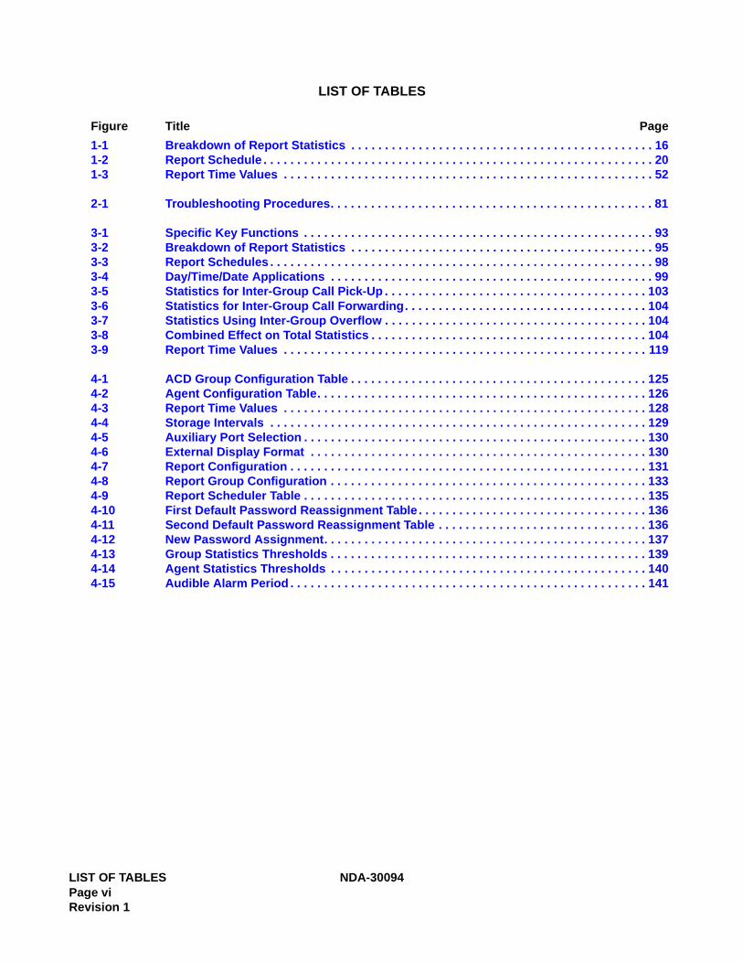
LIST OF TABLES
Figure Title Page
LIST OF TABLES NDA-30094Page viRevision 1
1-1 Breakdown of Report Statistics . . . . . . . . . . . . . . . . . . . . . . . . . . . . . . . . . . . . . . . . . . . . . 161-2 Report Schedule . . . . . . . . . . . . . . . . . . . . . . . . . . . . . . . . . . . . . . . . . . . . . . . . . . . . . . . . . . 201-3 Report Time Values . . . . . . . . . . . . . . . . . . . . . . . . . . . . . . . . . . . . . . . . . . . . . . . . . . . . . . . 52
2-1 Troubleshooting Procedures. . . . . . . . . . . . . . . . . . . . . . . . . . . . . . . . . . . . . . . . . . . . . . . . 81
3-1 Specific Key Functions . . . . . . . . . . . . . . . . . . . . . . . . . . . . . . . . . . . . . . . . . . . . . . . . . . . . 933-2 Breakdown of Report Statistics . . . . . . . . . . . . . . . . . . . . . . . . . . . . . . . . . . . . . . . . . . . . . 953-3 Report Schedules . . . . . . . . . . . . . . . . . . . . . . . . . . . . . . . . . . . . . . . . . . . . . . . . . . . . . . . . . 983-4 Day/Time/Date Applications . . . . . . . . . . . . . . . . . . . . . . . . . . . . . . . . . . . . . . . . . . . . . . . . 993-5 Statistics for Inter-Group Call Pick-Up . . . . . . . . . . . . . . . . . . . . . . . . . . . . . . . . . . . . . . . 1033-6 Statistics for Inter-Group Call Forwarding. . . . . . . . . . . . . . . . . . . . . . . . . . . . . . . . . . . . 1043-7 Statistics Using Inter-Group Overflow . . . . . . . . . . . . . . . . . . . . . . . . . . . . . . . . . . . . . . . 1043-8 Combined Effect on Total Statistics . . . . . . . . . . . . . . . . . . . . . . . . . . . . . . . . . . . . . . . . . 1043-9 Report Time Values . . . . . . . . . . . . . . . . . . . . . . . . . . . . . . . . . . . . . . . . . . . . . . . . . . . . . . 119
4-1 ACD Group Configuration Table . . . . . . . . . . . . . . . . . . . . . . . . . . . . . . . . . . . . . . . . . . . . 1254-2 Agent Configuration Table. . . . . . . . . . . . . . . . . . . . . . . . . . . . . . . . . . . . . . . . . . . . . . . . . 1264-3 Report Time Values . . . . . . . . . . . . . . . . . . . . . . . . . . . . . . . . . . . . . . . . . . . . . . . . . . . . . . 1284-4 Storage Intervals . . . . . . . . . . . . . . . . . . . . . . . . . . . . . . . . . . . . . . . . . . . . . . . . . . . . . . . . 1294-5 Auxiliary Port Selection . . . . . . . . . . . . . . . . . . . . . . . . . . . . . . . . . . . . . . . . . . . . . . . . . . . 1304-6 External Display Format . . . . . . . . . . . . . . . . . . . . . . . . . . . . . . . . . . . . . . . . . . . . . . . . . . 1304-7 Report Configuration . . . . . . . . . . . . . . . . . . . . . . . . . . . . . . . . . . . . . . . . . . . . . . . . . . . . . 1314-8 Report Group Configuration . . . . . . . . . . . . . . . . . . . . . . . . . . . . . . . . . . . . . . . . . . . . . . . 1334-9 Report Scheduler Table . . . . . . . . . . . . . . . . . . . . . . . . . . . . . . . . . . . . . . . . . . . . . . . . . . . 1354-10 First Default Password Reassignment Table . . . . . . . . . . . . . . . . . . . . . . . . . . . . . . . . . . 1364-11 Second Default Password Reassignment Table . . . . . . . . . . . . . . . . . . . . . . . . . . . . . . . 1364-12 New Password Assignment. . . . . . . . . . . . . . . . . . . . . . . . . . . . . . . . . . . . . . . . . . . . . . . . 1374-13 Group Statistics Thresholds . . . . . . . . . . . . . . . . . . . . . . . . . . . . . . . . . . . . . . . . . . . . . . . 1394-14 Agent Statistics Thresholds . . . . . . . . . . . . . . . . . . . . . . . . . . . . . . . . . . . . . . . . . . . . . . . 1404-15 Audible Alarm Period . . . . . . . . . . . . . . . . . . . . . . . . . . . . . . . . . . . . . . . . . . . . . . . . . . . . . 141
GENERAL DESCRIPTION
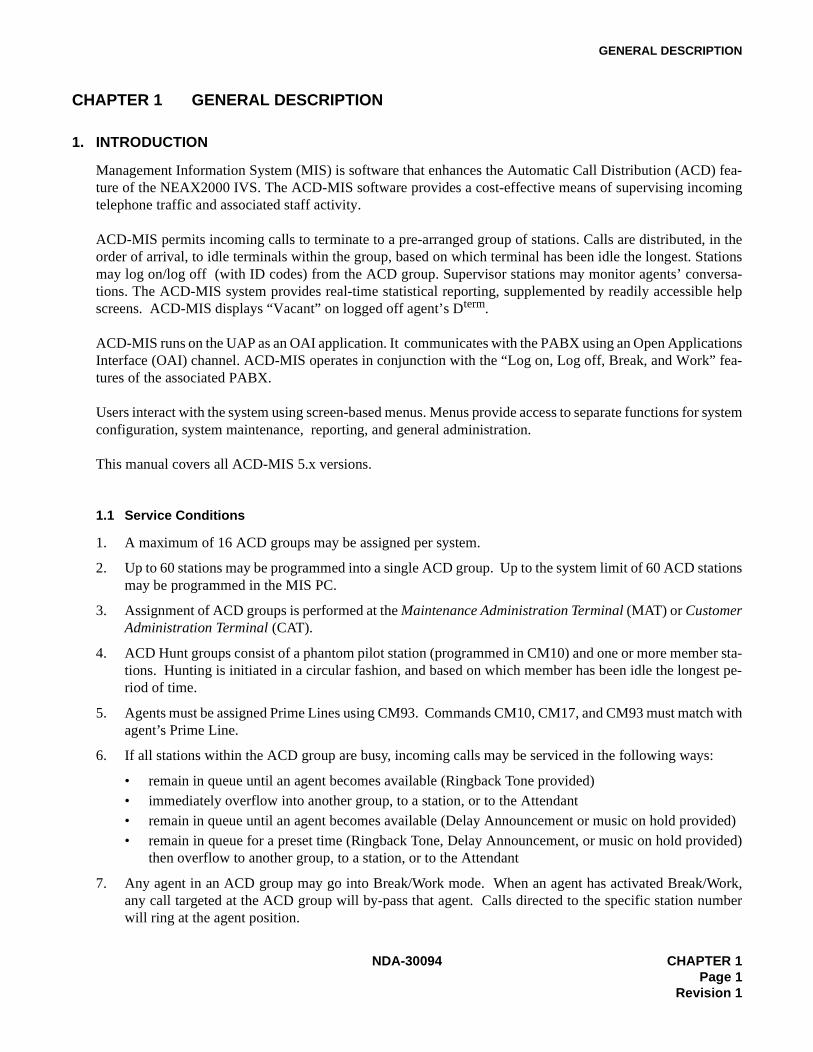
CHAPTER 1 GENERAL DESCRIPTION
1. INTRODUCTION
Management Information System (MIS) is software that enhances the Automatic Call Distribution (ACD) fea-ture of the NEAX2000 IVS. The ACD-MIS software provides a cost-effective means of supervising incomingtelephone traffic and associated staff activity.
ACD-MIS permits incoming calls to terminate to a pre-arranged group of stations. Calls are distributed, in theorder of arrival, to idle terminals within the group, based on which terminal has been idle the longest. Stationsmay log on/log off (with ID codes) from the ACD group. Supervisor stations may monitor agents’ conversa-tions. The ACD-MIS system provides real-time statistical reporting, supplemented by readily accessible helpscreens. ACD-MIS displays “Vacant” on logged off agent’s Dterm.
ACD-MIS runs on the UAP as an OAI application. It communicates with the PABX using an Open ApplicationsInterface (OAI) channel. ACD-MIS operates in conjunction with the “Log on, Log off, Break, and Work” fea-tures of the associated PABX. Users interact with the system using screen-based menus. Menus provide access to separate functions for systemconfiguration, system maintenance, reporting, and general administration.
This manual covers all ACD-MIS 5.x versions.
1.1 Service Conditions
1. A maximum of 16 ACD groups may be assigned per system.
2. Up to 60 stations may be programmed into a single ACD group. Up to the system limit of 60 ACD stationsmay be programmed in the MIS PC.
3. Assignment of ACD groups is performed at the Maintenance Administration Terminal (MAT) or CustomerAdministration Terminal (CAT).
4. ACD Hunt groups consist of a phantom pilot station (programmed in CM10) and one or more member sta-tions. Hunting is initiated in a circular fashion, and based on which member has been idle the longest pe-riod of time.
5. Agents must be assigned Prime Lines using CM93. Commands CM10, CM17, and CM93 must match withagent’s Prime Line.
6. If all stations within the ACD group are busy, incoming calls may be serviced in the following ways:
• remain in queue until an agent becomes available (Ringback Tone provided)• immediately overflow into another group, to a station, or to the Attendant• remain in queue until an agent becomes available (Delay Announcement or music on hold provided)• remain in queue for a preset time (Ringback Tone, Delay Announcement, or music on hold provided)
then overflow to another group, to a station, or to the Attendant
7. Any agent in an ACD group may go into Break/Work mode. When an agent has activated Break/Work,any call targeted at the ACD group will by-pass that agent. Calls directed to the specific station numberwill ring at the agent position.
NDA-30094 CHAPTER 1Page 1
Revision 1
GENERAL DESCRIPTION
8. Agents can log off their stations while idle, or while on an incoming outside call. If an agent is engaged inan ACD call and presses the Logged On, Break or Work Key, the status field of the STATUS MONITORScreen will change from ACD Call to Logged Off, Break, or Work after the call is terminated.
9. When the pilot station has set Call Forwarding - All Calls, incoming calls to the ACD group will be trans-ferred to the destination of that Call Forwarding - All Calls setting.
10. An ACD pilot number can be used as the destination station of Direct Inward Termination (DIT), or as adesignated Night Service station.
11. An ACD pilot number can be assigned as the destination station of Off-Hook Alarms, Priority Calls, andAttendant Night Transfer.
12. ACD group pilot numbers must not be placed in Station Hunting groups. The Station Hunting featurewould take priority over the ACD function.
13. When a call has terminated to ACD group A, and all stations in group A are busy, and group B is assignedas the overflow destination (using Call Forward-Busy), the call is transferred to group B. When all the sta-tions are busy in group B, the call queues onto ACD group A.
14. One overflow group can be provided for each ACD group. Overflow to another group is accomplished bysetting Call Forwarding - Busy Line at the pilot station of the first ACD group.
15. When an ACD station becomes available, the caller is immediately connected to the station, even if therecorded announcement is in progress.
16. Incoming call billing to the outside party starts when the first recorded announcement begins.
17. A PN-2DATA board is required to provide the recorded announcement.
18. A Delay Announcement service can be provided for DIT, DID, or a trunk call transferred by a station useror the Attendant to a ACD Group. Internal calls or station-to-station transferred calls to the ACD Groupcan go into the ACD queue but do not receive the Delay Announcement.
19. Incoming calls will hunt past an agent that failed to log off, if Call Forward - No Answer (to another ACDnumber) has been set.
20. If ACD member has set Call Forwarding - Busy Line or Call Forwarding - All Calls, it is skipped in ACDhunting. However, if the ACD member that has set Call Forwarding - Busy Line or Call Forwarding - AllCalls is called directly by another station, the Call Forwarding - Busy Line or Call Forwarding - All Callsdestination takes effect.
21. The destination for delay overflow may be set to any station or Attendant Console. If the destination fordelay overflow is an agent in the same ACD group, the call will stay in queue and hear the delay announce-ment repeated until the call is answered.
22. When the destination of delay overflow is a busy station (which is not a pilot of another ACD group), theincoming call will hear delay announcement for the programmed cycle. When the destination station be-comes idle, the next cycle will provide overflow to the destination station.
23. If the destination station of delay overflow is in a hunt group, the hunt feature is followed.
24. If the destination station of delay overflow is set for Call Forwarding - Busy Line or Call Forwarding - AllCalls, the call forwarding feature will be followed.
25. If the destination station of delay overflow is set to Call Forwarding - Outside, the call will stay in the ACDqueue and hear the delay announcement repeated until the call is answered.
CHAPTER 1 NDA-30094Page 2Revision 1

GENERAL DESCRIPTION
26. If the destination station of delay overflow is set to Do Not Disturb, the call will stay in the ACD queue andhear the delay announcement repeated until the call is answered.
27. Second Delay Announcement service can be provided for DIT, DID, or a trunk call transferred by a stationuser or the Attendant to an ACD Group, after the first Delay Announcement.
28. Priority Queuing is available for incoming trunk calls. The queue priorities are assigned on a trunk routebasis or per station number on DID call.
29. The maximum number of queuing in each ACD group (hereinafter called Queue Size) can be specified bythe system data. When the number of queuing calls reaches the pre-assigned queue size, new calls receiveBusy Tone. Depending on the queue size, the Overflowed ACD call indication on a Multiline Terminal oron the external indicator is provided as shown by the information that follows:
Queue Size assigned by system data=S; Number of queuing calls=N
30. An incoming Listed Directory Number (LDN) received from Direct-Inward Dialing (DID) line can be dis-played on the LCD of a Multiline Terminal in the ACD group. System data is assigned on a trunk routebasis.
31. A maximum of 90 ACD-MIS Log-On ID codes may be assigned per system.
32. Blank name will be shown on logged out agents and all statistic data will be cleared. When an agent hascompletely logged in, the agent’s name will be shown in the name field. Other statistical values for thatagent will be displayed (version 4.11 - 4.42).
33. Agents can log on at any phone in their group. The program will keep track of their activity for the statistic.
34. When OAI is disconnected for any reason, all agents are automatically logged off. When OAI is reconnect-ed, they have to log on again.
35. Chimes for the Dterm OAI keys can be programmed to be sent or not in PABX programming. Tones foranalog stations are set up using an edit program for file MIS.TON.
36. The pilot station of the ACD group must be programmed in MIS station configuration (analog non-equipped).
37. There is a limitation of 100 max. incoming calls to an ACD group at one time.
38. MSF OAI keys for Log On with ID#, Break, and Work should be assigned to keys 1, 2, and 3, respectively,of each Dterm set requiring MIS reporting.
39. Headset/handset button must be used in conjunction with an ADA adapter to switch the conversation be-tween headset and handset.
CONDITIONS
LAMP INDICATION
Multiline Terminal External Indicator
S = 1 Steady on red Lamp on
1 ≤ N < S(S ≠ 1)
Steady on red Lamp off
S ≤ N(S ≠ 1)
Flashing red Lamp on
NDA-30094 CHAPTER 1Page 3
Revision 1
GENERAL DESCRIPTION
40. An agent on an outgoing call via the ACD line with MIS status set to available will stay available. TheACD-MIS does not have an outgoing call status.
41. When using the Create Report function, with FD inserted into Drive A, specify the destination as File. Thereport is saved as an ASCII file on the FD and can be imported into a spreadsheet program (e.g. Microsoft’sExcel).
42. When using the Create Report function, specify the destination as Printer. A dot matrix or laser printer canbe used to print the designated report.
43. ACD-MIS displays “Vacant” on logged off agent’s Dterm.
CHAPTER 1 NDA-30094Page 4Revision 1
GENERAL DESCRIPTION
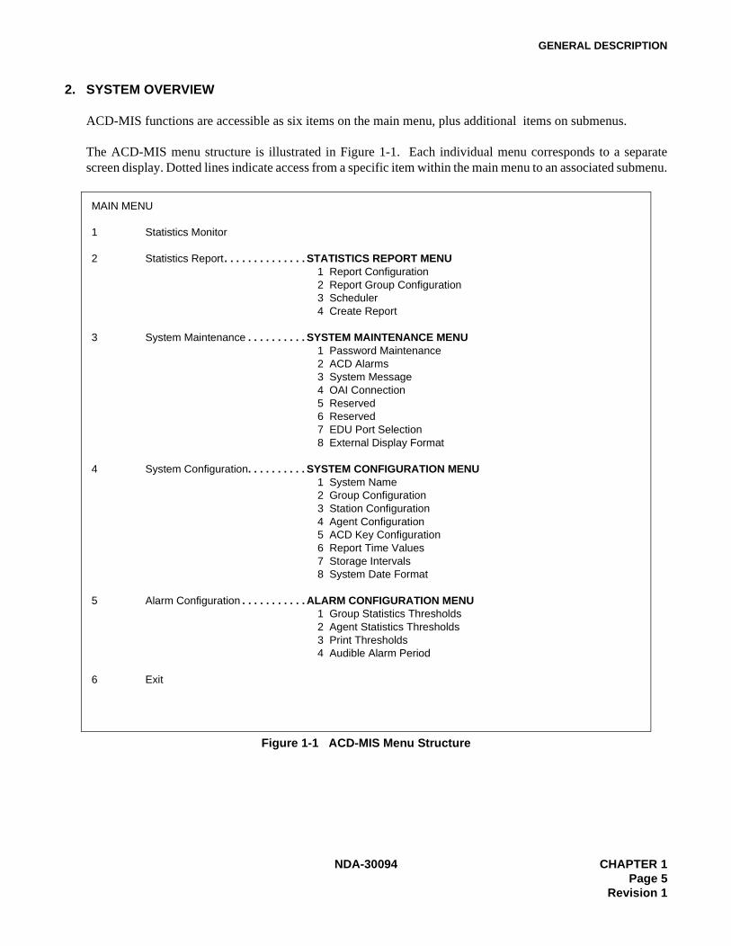
2. SYSTEM OVERVIEW
ACD-MIS functions are accessible as six items on the main menu, plus additional items on submenus.
The ACD-MIS menu structure is illustrated in Figure 1-1. Each individual menu corresponds to a separatescreen display. Dotted lines indicate access from a specific item within the main menu to an associated submenu.
Figure 1-1 ACD-MIS Menu Structure
MAIN MENU
1 Statistics Monitor
2 Statistics Report. . . . . . . . . . . . . . STATISTICS REPORT MENU1 Report Configuration2 Report Group Configuration3 Scheduler4 Create Report
3 System Maintenance . . . . . . . . . . SYSTEM MAINTENANCE MENU1 Password Maintenance2 ACD Alarms3 System Message4 OAI Connection5 Reserved6 Reserved7 EDU Port Selection8 External Display Format
4 System Configuration. . . . . . . . . . SYSTEM CONFIGURATION MENU1 System Name2 Group Configuration3 Station Configuration4 Agent Configuration5 ACD Key Configuration6 Report Time Values7 Storage Intervals8 System Date Format
5 Alarm Configuration . . . . . . . . . . . ALARM CONFIGURATION MENU1 Group Statistics Thresholds2 Agent Statistics Thresholds3 Print Thresholds4 Audible Alarm Period
6 Exit
NDA-30094 CHAPTER 1Page 5
Revision 1

GENERAL DESCRIPTION
2.1 Main Menu
ACD-MIS’s main menu includes six menu items, described below, plus submenus. Each menu item is de-scribed in detail in the section referenced in brackets.
1 - Statistics Monitor Allows a general study of recorded statistics on received calls and their handlingby assigned agents. (See “Statistics Monitor” , Section 3.3.)
2 - Statistics Report Sets the structure of various reports, together with their output requirements forprintout or display. This is done using the items listed in the associated submenu.(See “Statistics Report” , Section 3.4.)
3 - System Maintenance Through its submenu, provides functions for system administration and manage-ment (including security passwords, two areas of alarm supervision, OAI control).(See “System Maintenance” , Section 3.5.)
In addition, two menu items relate to set-up of the External Display Unit. (See “Ex-ternal Display Unit (EDU)” , Section 3.2.)
4 - System Configuration Accesses procedures to program customer data during installation or when thosespecifications need to be changed.
The associated submenu includes facilities for programming the customer's pre-ferred name for the system, detailing different ACD groups and their assignedagents, and setting basic parameters for the Statistics Monitor feature. (See “Sys-tem Configuration” , Section 3.6.)
5 - Alarm Configuration From its submenu, provides for the setting of call handling operational limits on aper-ACD group basis. If any limit is subsequently exceeded, visual warning indi-cations are initiated to alert supervisory staff. The settings can be printed for ref-erence. It also includes a facility for controlling the audible alarm associated withthe Statistics Monitor feature. (See “Alarm Configuration” , Section 3.7.)
6 - Exit Shuts down ACD-MIS (and returns to UNIX prompt) for maintenance purposes.Its use must be restricted, because call data from the PABX cannot be processedin this mode. (See “Exit” , Section 3.8.)
CHAPTER 1 NDA-30094Page 6Revision 1
GENERAL DESCRIPTION
3. SYSTEM FEATURES
This document covers ACD-MIS functions. Information is presented in the order in which items appear on thesystem menu.
3.1 Terms and Definitions
The following terms and definitions are used in ACD-MIS’s statistical reports. Some terms apply to all statisti-cal reports; others apply to selected statistics (i.e., for system, groups, or agents). Times are measured in minutesand seconds (and displayed as mm:ss).
GOS % (GRADE OF SERVICE % - All Statistics):GOS is the cumulative percentage of ACD calls that have been answered within a preset number of secondsthroughout the day (i.e., from midnight). The value is calculated by the formula:
Number of calls answered within the specified time limit (seconds) x 100%Total number of answered calls for the day
AVG. TIME TALK (AVERAGE TIME TALKING - All Statistics):The average time agents spend in conversation on ACD calls.
AVG. TIME ANSW (AVERAGE TIME ANSWER - All Statistics):The average time taken to answer ACD calls. For system and group statistics, this value is measured fromthe moment a call enters the queue. For agent statistics, this value is measured only from the moment anagent is rung and therefore excludes time spent waiting in the queue.
WAITING LONG (WAITING LONGEST - System/Group Statistics):Amount of time the longest waiting ACD call has been queued.
WAITING NO (WAITING NUMBER - System/Group Statistics):The number of ACD calls currently in the queue.
NO. of CALLS IN (NUMBER OF CALLS IN - All Statistics):The total number of ACD calls received since midnight, including those abandoned.
NO. of CALLS NWAIT (NUMBER OF CALLS NO WAITING - System/Group Statistics):The total number of ACD calls to ring agents without first being queued, since midnight. This includesany calls subsequently abandoned.
NO. of CALLS ANSW (NUMBER OF CALLS ANSWERED - All Statistics):The total number of ACD calls answered since midnight.
NO. of CALLS ABD-Q (NUMBER OF CALLS ABANDONED QUEUE - System/Group Statistics):The total number of ACD calls abandoned since midnight while waiting in the queue.
NO. of CALLS ABD-R (NUMBER OF CALLS ABANDONED RINGING - System/Group Statistics):The total number of ACD calls abandoned since midnight while ringing an agent.
NDA-30094 CHAPTER 1Page 7
Revision 1
GENERAL DESCRIPTION
NO. of CALLS NACD (NUMBER OF CALLS NON-ACD - All Statistics):The total number of non-ACD calls received (by AVAILABLE agents only), since midnight. This includesany subsequently abandoned calls.
NO. of AGENTS in STATUS (System/Group Statistics):The total number of agents currently:
RING being rung by ACD calls either queued or not queued)TALK occupied on ACD callsFREE not occupied on ACD calls/logged onLOFF logged out from the ACD groupNACD occupied on direct-in callsBREAK agent in Break modeWORK agent in Work mode
AVERAGE TIME ABD-Q (AVERAGE TIME ABANDON QUEUE - System/Group Statistics):The average time any callers wait in the queue before abandoning.
AVERAGE TIME ABD-R (AVERAGE TIME ABANDON RING - System/Group Statistics):The average time any callers wait (including time in queue) before abandoning, while ringing an agent.
AVERAGE TIME NACD (AVERAGE TIME NON-ACD - All Statistics):The average time agents are occupied (including being rung) by non-ACD calls.
AVERAGE TIME AVAIL (AVERAGE TIME AVAILABLE - All Statistics):The average time agents spend waiting between both ACD and non-ACD calls while logged on.
STATUS (Agent Statistics only):Indication of the current situation of the individual agent as one of:
NO STAT Initial (temporary) system indicationAVAILABLE Not presently occupied on an ACD call or non-ACD callACD RINGING Being rung by a waiting ACD callACD CALL Occupied on an ACD callNON ACD Occupied on a direct-in call to agent station numberLOGGED OFF Logged out from the ACD group. No monitoring by ACD-MIS of any calls until
agent logs on again.WORK Agent is in Work modeBREAK Agent is in Break mode
TIME (Agent Statistics only):The time an agent has been in the indicated STATUS.
NO. of CALLS ABND (NUMBER OF CALLS ABANDONED - Agent Statistics only):The total number of calls abandoned since midnight, either while queued or ringing the agent.
AVERAGE TIME ABND (AVERAGE TIME ABANDONED - Agent Statistics)The average time the specified agent is rung before callers abandon.
CHAPTER 1 NDA-30094Page 8Revision 1
GENERAL DESCRIPTION
3.1.1 Other Terms
Other terms (described below) appear on ACD-MIS’s screens.
System and Group Statistics Displays:
Group No. The pilot extension number of the individual ACD groups (e.g. 6300, 6336)
Group Name The title system or the specified name of the ACD group for group statistics (e.g., RESER-VATION, INQUIRIES)
Indial No. A maximum of eight digits, this includes the indial prefix digits and pilot extension numberfor the ACD groups:
Prefix Extension2233 63002233 6336
Agent Statistics Displays:
Agent No. The extension number of the agent position
Agent Name The normally assigned surname of the agent when logged on
Group No. The pilot extension number of the ACD group (e.g., 6300, 6336) to which the agent belongs
TN No. The PABX tenant number for the ACD group
Handset Type The type of telephone handset (Analog or Dterm) which the agent uses
NDA-30094 CHAPTER 1Page 9
Revision 1
GENERAL DESCRIPTION
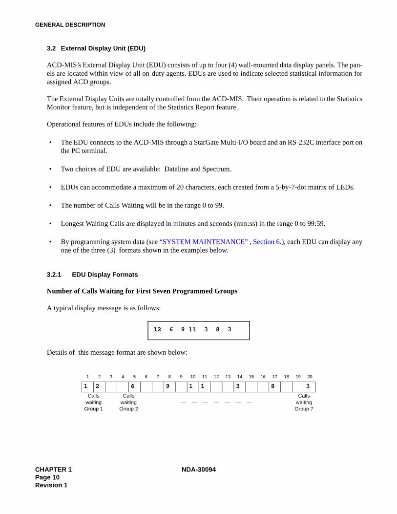
3.2 External Display Unit (EDU)
ACD-MIS’s External Display Unit (EDU) consists of up to four (4) wall-mounted data display panels. The pan-els are located within view of all on-duty agents. EDUs are used to indicate selected statistical information forassigned ACD groups.
The External Display Units are totally controlled from the ACD-MIS. Their operation is related to the StatisticsMonitor feature, but is independent of the Statistics Report feature.
Operational features of EDUs include the following:
• The EDU connects to the ACD-MIS through a StarGate Multi-I/O board and an RS-232C interface port onthe PC terminal.
• Two choices of EDU are available: Dataline and Spectrum.
• EDUs can accommodate a maximum of 20 characters, each created from a 5-by-7-dot matrix of LEDs.
• The number of Calls Waiting will be in the range 0 to 99.
• Longest Waiting Calls are displayed in minutes and seconds (mm:ss) in the range 0 to 99:59.
• By programming system data (see “SYSTEM MAINTENANCE” , Section 6.), each EDU can display anyone of the three (3) formats shown in the examples below.
3.2.1 EDU Display Formats
Number of Calls Waiting for First Seven Programmed Groups
A typical display message is as follows:
Details of this message format are shown below:
1 2 3 4 5 6 7 8 9 10 11 12 13 14 15 16 17 18 19 20
1 2 6 9 1 1 3 8 3
Calls waiting Group 1
Calls waiting Group 2
— — — — — — —Calls
waiting Group 7
12 6 9 11 3 8 3
CHAPTER 1 NDA-30094Page 10Revision 1

GENERAL DESCRIPTION
Number of Calls Waiting + Longest Waiting Time for First Two Programmed Groups
A typical display message is as follows:
Details of this message format are shown below:
Group Name + Calls Waiting + Longest Waiting Time for First Programmed Group
A typical display message is as follows:
Details of this message format are shown below:
1 2 3 4 5 6 7 8 9 10 11 12 13 14 15 16 17 18 19 20
1 2 1 : 1 2 7 5 6
Calls waiting
Longest wait mm:ss Calls waiting
Longest wait mm:ss
Group 1 Group 2
1 2 3 4 5 6 7 8 9 10 11 12 13 14 15 16 17 18 19 20
R E S E R V A T I O N 1 0 1 : 3 2
Name: maximum 11 characters Calls waiting
Longest wait mm:ss
Group 1
12 1:12 7 56
RESERVATION 10 1:32
NDA-30094 CHAPTER 1Page 11
Revision 1
GENERAL DESCRIPTION
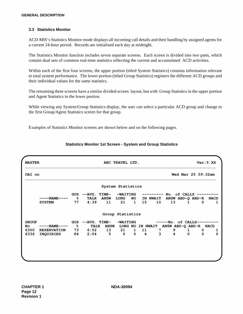
3.3 Statistics Monitor
ACD-MIS’s Statistics Monitor mode displays all incoming call details and their handling by assigned agents fora current 24-hour period. Records are initialized each day at midnight.
The Statistics Monitor function includes seven separate screens. Each screen is divided into two parts, whichcontain dual sets of common real-time statistics reflecting the current and accumulated ACD activities.
Within each of the first four screens, the upper portion (titled System Statistics) contains information relevantto total system performance. The lower portion (titled Group Statistics) registers the different ACD groups andtheir individual values for the same statistics.
The remaining three screens have a similar divided-screen layout, but with Group Statistics in the upper portionand Agent Statistics in the lower portion.
While viewing any System/Group Statistics display, the user can select a particular ACD group and change tothe first Group/Agent Statistics screen for that group.
Examples of Statistics Monitor screens are shown below and on the following pages.
Statistics Monitor 1st Screen - System and Group Statistics
MASTER ABC TRAVEL LTD. Ver:5.XX________________________________________________________________________________
OAI on Wed Mar 25 09:32am________________________________________________________________________________
System Statistics
GOS --AVG. TIME- -WAITING --------- No. of CALLS -------------NAME---- % TALK ANSW LONG NO IN NWAIT ANSW ABD-Q ABD-R NACDSYSTEM 77 4:39 11 21 1 15 10 13 1 0 1
Group Statistics
GROUP GOS --AVG. TIME- -WAITING -----No. of CALLS---------No ----NAME---- % TALK ANSW LONG NO IN NWAIT ANSW ABD-Q ABD-R NACD6300 RESERVATION 73 6:52 13 21 1 11 7 9 1 0 16336 INQUIRIES 84 2:04 5 0 0 4 3 4 0 0 0
CHAPTER 1 NDA-30094Page 12Revision 1
GENERAL DESCRIPTION
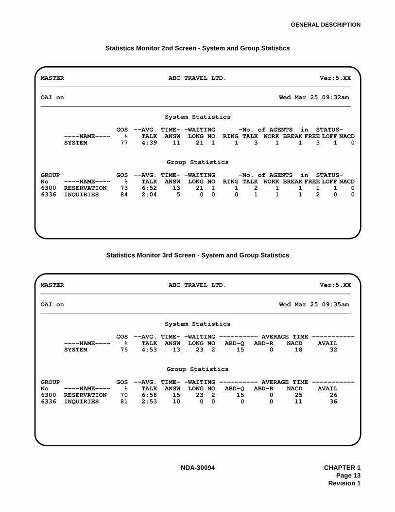
Statistics Monitor 2nd Screen - System and Group Statistics
Statistics Monitor 3rd Screen - System and Group Statistics
MASTER ABC TRAVEL LTD. Ver:5.XX________________________________________________________________________________
OAI on Wed Mar 25 09:32am________________________________________________________________________________
System Statistics
GOS --AVG. TIME- -WAITING -No. of AGENTS in STATUS-----NAME---- % TALK ANSW LONG NO RING TALK WORK BREAK FREE LOFF NACDSYSTEM 77 4:39 11 21 1 1 3 1 1 3 1 0
Group Statistics
GROUP GOS --AVG. TIME- -WAITING -No. of AGENTS in STATUS-No ----NAME---- % TALK ANSW LONG NO RING TALK WORK BREAK FREE LOFF NACD6300 RESERVATION 73 6:52 13 21 1 1 2 1 1 1 1 06336 INQUIRIES 84 2:04 5 0 0 0 1 1 1 2 0 0
MASTER ABC TRAVEL LTD. Ver:5.XX________________________________________________________________________________
OAI on Wed Mar 25 09:35am________________________________________________________________________________
System Statistics
GOS --AVG. TIME- -WAITING ---------- AVERAGE TIME ---------------NAME---- % TALK ANSW LONG NO ABD-Q ABD-R NACD AVAILSYSTEM 75 4:53 13 23 2 15 0 18 32
Group Statistics
GROUP GOS --AVG. TIME- -WAITING ---------- AVERAGE TIME -----------No ----NAME---- % TALK ANSW LONG NO ABD-Q ABD-R NACD AVAIL6300 RESERVATION 70 6:58 15 23 2 15 0 25 266336 INQUIRIES 81 2:53 10 0 0 0 0 11 36
NDA-30094 CHAPTER 1Page 13
Revision 1
GENERAL DESCRIPTION
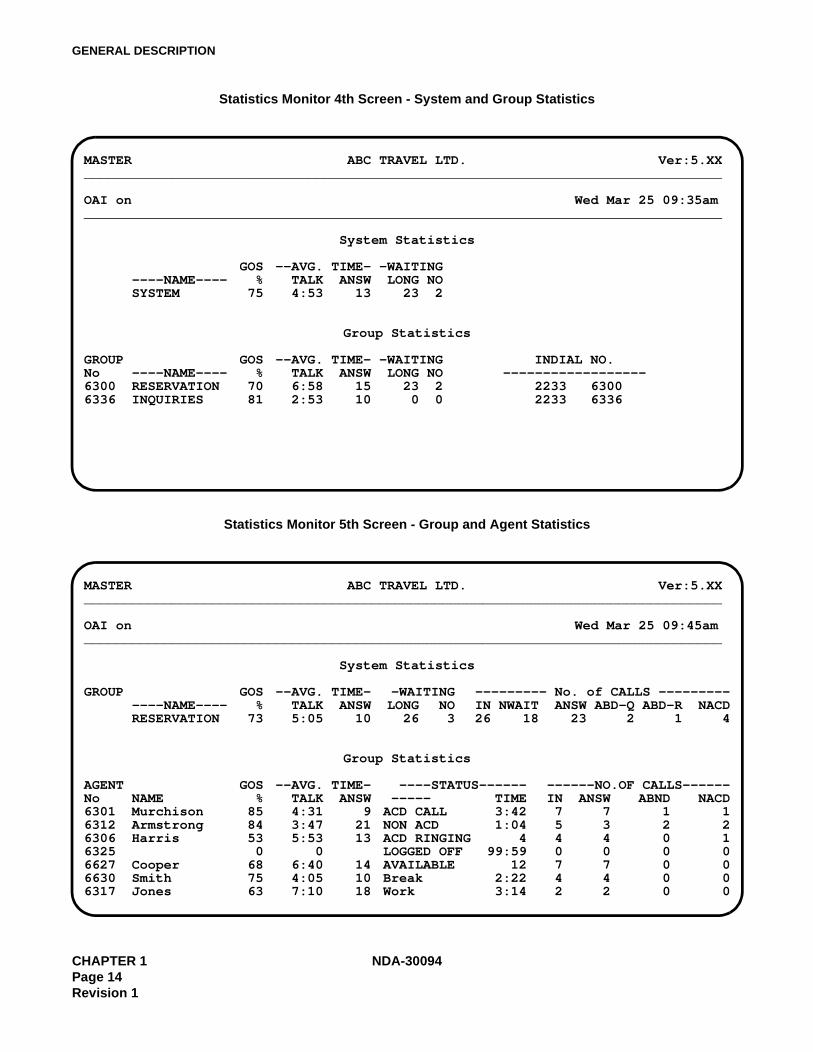
Statistics Monitor 4th Screen - System and Group Statistics
Statistics Monitor 5th Screen - Group and Agent Statistics
MASTER ABC TRAVEL LTD. Ver:5.XX________________________________________________________________________________
OAI on Wed Mar 25 09:35am________________________________________________________________________________
System Statistics
GOS --AVG. TIME- -WAITING----NAME---- % TALK ANSW LONG NOSYSTEM 75 4:53 13 23 2
Group Statistics
GROUP GOS --AVG. TIME- -WAITING INDIAL NO.No ----NAME---- % TALK ANSW LONG NO ------------------6300 RESERVATION 70 6:58 15 23 2 2233 63006336 INQUIRIES 81 2:53 10 0 0 2233 6336
MASTER ABC TRAVEL LTD. Ver:5.XX________________________________________________________________________________
OAI on Wed Mar 25 09:45am________________________________________________________________________________
System Statistics
GROUP GOS --AVG. TIME- -WAITING --------- No. of CALLS -------------NAME---- % TALK ANSW LONG NO IN NWAIT ANSW ABD-Q ABD-R NACDRESERVATION 73 5:05 10 26 3 26 18 23 2 1 4
Group Statistics
AGENT GOS --AVG. TIME- ----STATUS------ ------NO.OF CALLS------No NAME % TALK ANSW ----- TIME IN ANSW ABND NACD6301 Murchison 85 4:31 9 ACD CALL 3:42 7 7 1 16312 Armstrong 84 3:47 21 NON ACD 1:04 5 3 2 26306 Harris 53 5:53 13 ACD RINGING 4 4 4 0 16325 0 0 LOGGED OFF 99:59 0 0 0 06627 Cooper 68 6:40 14 AVAILABLE 12 7 7 0 06630 Smith 75 4:05 10 Break 2:22 4 4 0 06317 Jones 63 7:10 18 Work 3:14 2 2 0 0
CHAPTER 1 NDA-30094Page 14Revision 1
GENERAL DESCRIPTION
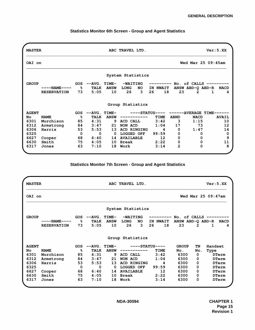
Statistics Monitor 6th Screen - Group and Agent Statistics
Statistics Monitor 7th Screen - Group and Agent Statistics
MASTER ABC TRAVEL LTD. Ver:5.XX________________________________________________________________________________
OAI on Wed Mar 25 09:45am________________________________________________________________________________
System Statistics
GROUP GOS --AVG. TIME- -WAITING --------- No. of CALLS -------------NAME---- % TALK ANSW LONG NO IN NWAIT ANSW ABD-Q ABD-R NACDRESERVATION 73 5:05 10 26 3 26 18 23 2 1 4
Group Statistics
AGENT GOS --AVG. TIME- ----STATUS---- ------AVERAGE TIME------No NAME % TALK ANSW ----------- TIME ABND NACD AVAIL6301 Murchison 85 4:31 9 ACD CALL 3:42 3 1:15 106312 Armstrong 84 3:47 21 NON ACD 1:04 17 73 126306 Harris 53 5:53 13 ACD RINGING 4 0 1:47 146325 0 0 0 LOGGED OFF 99:59 0 0 06627 Cooper 68 6:40 14 AVAILABLE 12 0 0 96630 Smith 75 4:05 10 Break 2:22 0 0 116317 Jones 63 7:10 18 Work 3:14 2 0 8
MASTER ABC TRAVEL LTD. Ver:5.XX________________________________________________________________________________
OAI on Wed Mar 25 09:47am________________________________________________________________________________
System Statistics
GROUP GOS --AVG. TIME- -WAITING --------- No. of CALLS -------------NAME---- % TALK ANSW LONG NO IN NWAIT ANSW ABD-Q ABD-R NACDRESERVATION 73 5:05 10 26 3 26 18 23 2 1 4
Group Statistics
AGENT GOS --AVG. TIME- ----STATUS---- GROUP TN HandsetNo NAME % TALK ANSW ----------- TIME No. No. Type6301 Murchison 85 4:31 9 ACD CALL 3:42 6300 0 DTerm6312 Armstrong 84 3:47 21 NON ACD 1:04 6300 0 DTerm6306 Harris 53 5:53 13 ACD RINGING 4 6300 0 DTerm6325 0 0 0 LOGGED OFF 99:59 6300 0 DTerm6627 Cooper 68 6:40 14 AVAILABLE 12 6300 0 DTerm6630 Smith 75 4:05 10 Break 2:22 6300 0 DTerm6317 Jones 63 7:10 18 Work 3:14 6300 0 DTerm
NDA-30094 CHAPTER 1Page 15
Revision 1
GENERAL DESCRIPTION
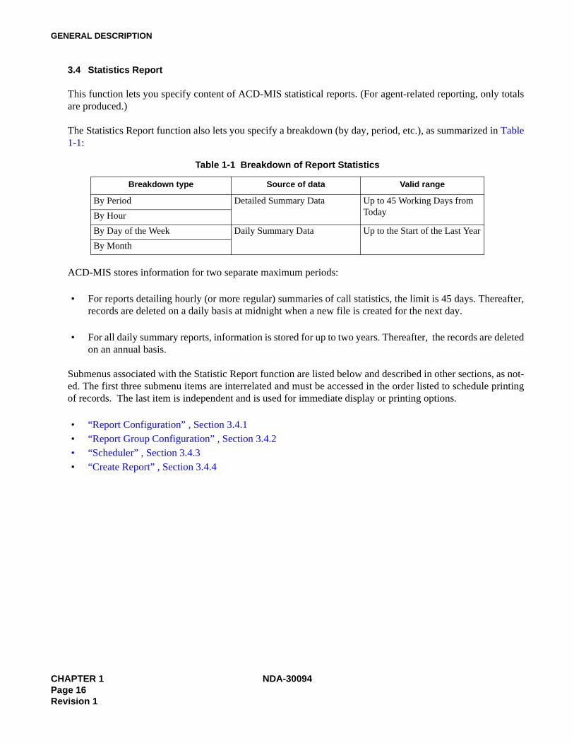
3.4 Statistics Report
This function lets you specify content of ACD-MIS statistical reports. (For agent-related reporting, only totalsare produced.)
The Statistics Report function also lets you specify a breakdown (by day, period, etc.), as summarized in Table1-1:
ACD-MIS stores information for two separate maximum periods:
• For reports detailing hourly (or more regular) summaries of call statistics, the limit is 45 days. Thereafter,records are deleted on a daily basis at midnight when a new file is created for the next day.
• For all daily summary reports, information is stored for up to two years. Thereafter, the records are deletedon an annual basis.
Submenus associated with the Statistic Report function are listed below and described in other sections, as not-ed. The first three submenu items are interrelated and must be accessed in the order listed to schedule printingof records. The last item is independent and is used for immediate display or printing options.
• “Report Configuration” , Section 3.4.1• “Report Group Configuration” , Section 3.4.2 • “Scheduler” , Section 3.4.3• “Create Report” , Section 3.4.4
Table 1-1 Breakdown of Report Statistics
Breakdown type Source of data Valid range
By Period Detailed Summary Data Up to 45 Working Days from TodayBy Hour
By Day of the Week Daily Summary Data Up to the Start of the Last Year
By Month
CHAPTER 1 NDA-30094Page 16Revision 1

GENERAL DESCRIPTION
3.4.1 Report Configuration
The Report Configuration option lets you set a variety of report formats by combining a number of parameters.Any Report Configuration can be modified or deleted.
Report Configuration Screen
Report Name the title you assign to a report (up to 20 alphanumeric characters).
Report Type specifies one of the following ten reports available in the system:
• Calls Waiting • Group Workload• Calls Abandoned • Group Performance• Call Duration • Agent Performance• Traffic Analysis • Agent Demand• Group Break and Work • Agent Break and Work
These reports are described in “Report Data” , Section 3.4.5.
Class defines the report content and format according to:Full Statistics for all existing ACD groups are included in one report.All The same statistics are presented in separate reports for each ACD
group.Selected Specified when reporting on a single ACD group.
MASTER ABC TRAVEL LTD. Ver:5.XX________________________________________________________________________________
OAI on Wed Mar 25 09:48am________________________________________________________________________________
Report Configuration
Report Name : Duration - P.M. Action : Modify
Report Type : Call Duration
Class : Selected
Date Type : last month
Breakdown : by period
________________________________________________________________________________
a by period c daily e weeklyb hourly d monthly f total
NDA-30094 CHAPTER 1Page 17
Revision 1

GENERAL DESCRIPTION
Date Type selects statistics for one of ten reporting periods:TodayYesterdayThis week (Sunday to Saturday)Last week (Sunday to Saturday)This monthLast monthThis year up to today (i.e., Year To Date)Last yearFor date (any specified day)Date range (any specified calendar period)
Break Down tallies statistics per line, for the specified reporting period, according to the followingoptions:a - By period in 10-, 15-, 20-, 30- or 60-minute time segments within each hour, de-
pending on original data set (see Section 3.6.5 - Storage Intervals)
b - Hourly in hour blocks of time, irrespective of any data settings as above
c - Daily per-day totals for the specified period
d - Monthly per-calendar-month totals for the specified period
e - Weekday individual totals for the relevant days of the week
f - Total per-ACD-group totals (i.e., where Class is Full or All), for the speci-fied period.
Note: Certain combinations of the Date Type and Breakdown parameters are not legitimate (Today+ Monthly, For Date + Monthly, etc.). In such cases a warning message displays.
Note: Breakdown is applicable to all ACD group reports but has no meaning for the Agent Perfor-mance Report (because only total statistics are produced).
Action allows existing Report Configurations to be modified or deleted:
Modify change any current parameter selection(s)
Delete erase the entire configuration from system memory
CHAPTER 1 NDA-30094Page 18Revision 1
GENERAL DESCRIPTION
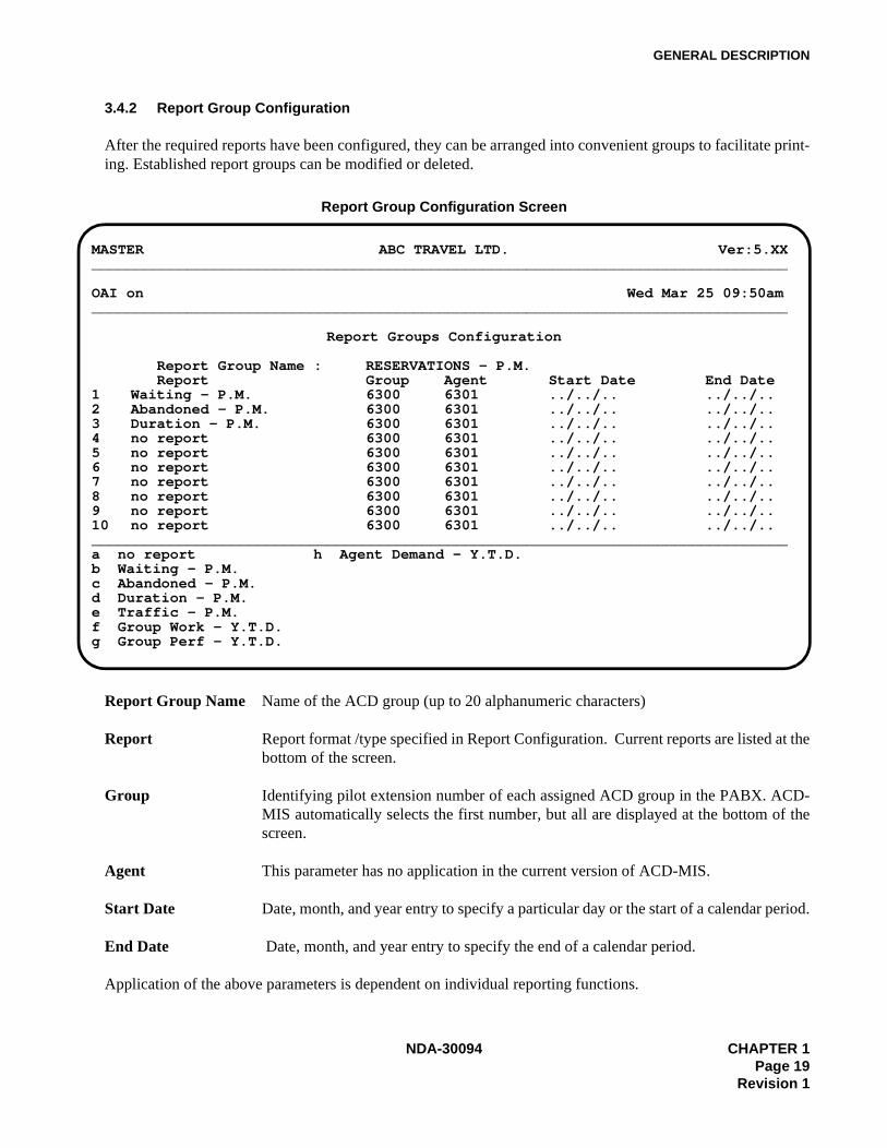
3.4.2 Report Group Configuration
After the required reports have been configured, they can be arranged into convenient groups to facilitate print-ing. Established report groups can be modified or deleted.
Report Group Configuration Screen
Report Group Name Name of the ACD group (up to 20 alphanumeric characters)
Report Report format /type specified in Report Configuration. Current reports are listed at thebottom of the screen.
Group Identifying pilot extension number of each assigned ACD group in the PABX. ACD-MIS automatically selects the first number, but all are displayed at the bottom of thescreen.
Agent This parameter has no application in the current version of ACD-MIS.
Start Date Date, month, and year entry to specify a particular day or the start of a calendar period.
End Date Date, month, and year entry to specify the end of a calendar period.
Application of the above parameters is dependent on individual reporting functions.
MASTER ABC TRAVEL LTD. Ver:5.XX________________________________________________________________________________
OAI on Wed Mar 25 09:50am________________________________________________________________________________
Report Groups Configuration
Report Group Name : RESERVATIONS - P.M.Report Group Agent Start Date End Date
1 Waiting - P.M. 6300 6301 ../../.. ../../..2 Abandoned - P.M. 6300 6301 ../../.. ../../..3 Duration - P.M. 6300 6301 ../../.. ../../..4 no report 6300 6301 ../../.. ../../..5 no report 6300 6301 ../../.. ../../..6 no report 6300 6301 ../../.. ../../..7 no report 6300 6301 ../../.. ../../..8 no report 6300 6301 ../../.. ../../..9 no report 6300 6301 ../../.. ../../..10 no report 6300 6301 ../../.. ../../..________________________________________________________________________________a no report h Agent Demand - Y.T.D.b Waiting - P.M.c Abandoned - P.M.d Duration - P.M.e Traffic - P.M.f Group Work - Y.T.D.g Group Perf - Y.T.D.
NDA-30094 CHAPTER 1Page 19
Revision 1
GENERAL DESCRIPTION
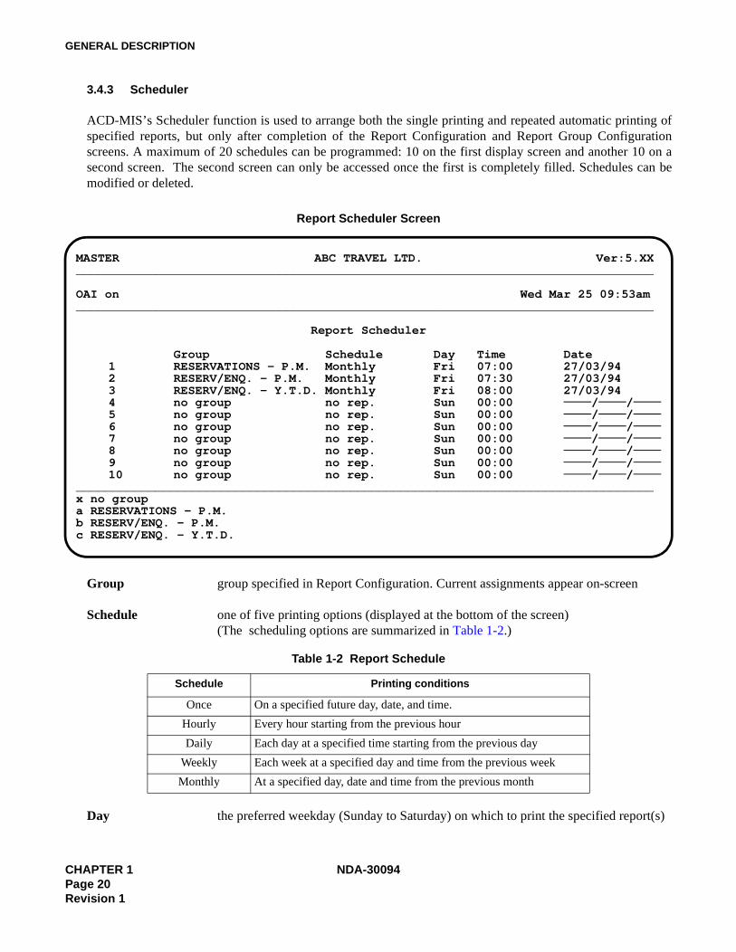
3.4.3 Scheduler
ACD-MIS’s Scheduler function is used to arrange both the single printing and repeated automatic printing ofspecified reports, but only after completion of the Report Configuration and Report Group Configurationscreens. A maximum of 20 schedules can be programmed: 10 on the first display screen and another 10 on asecond screen. The second screen can only be accessed once the first is completely filled. Schedules can bemodified or deleted.
Report Scheduler Screen
Group group specified in Report Configuration. Current assignments appear on-screen
Schedule one of five printing options (displayed at the bottom of the screen)(The scheduling options are summarized in Table 1-2.)
Day the preferred weekday (Sunday to Saturday) on which to print the specified report(s)
Table 1-2 Report Schedule
Schedule Printing conditions
Once On a specified future day, date, and time.
Hourly Every hour starting from the previous hour
Daily Each day at a specified time starting from the previous day
Weekly Each week at a specified day and time from the previous week
Monthly At a specified day, date and time from the previous month
MASTER ABC TRAVEL LTD. Ver:5.XX________________________________________________________________________________
OAI on Wed Mar 25 09:53am________________________________________________________________________________
Report Scheduler
Group Schedule Day Time Date1 RESERVATIONS - P.M. Monthly Fri 07:00 27/03/942 RESERV/ENQ. - P.M. Monthly Fri 07:30 27/03/943 RESERV/ENQ. - Y.T.D. Monthly Fri 08:00 27/03/944 no group no rep. Sun 00:00 / /
5 no group no rep. Sun 00:00 / /
6 no group no rep. Sun 00:00 / /
7 no group no rep. Sun 00:00 / /
8 no group no rep. Sun 00:00 / /
9 no group no rep. Sun 00:00 / /
10 no group no rep. Sun 00:00 / /
________________________________________________________________________________x no groupa RESERVATIONS - P.M.b RESERV/ENQ. - P.M.c RESERV/ENQ. - Y.T.D.
CHAPTER 1 NDA-30094Page 20Revision 1

GENERAL DESCRIPTION
Time the hour and minute of the specified day on which to print the report(s) [required entry]
Date the date, month, and year on or after which any report(s) is to be printed [required en-try]
Not all parameters always need to be entered. (More details are included in Chapter 3, “OPERATING PRO-CEDURES,” .
3.4.4 Create Report
ACD-MIS’s Create Report function is used to request an immediate one-time display or printout for an individ-ually selected report.
Report Parameter Screen
Report Type (same as in Report Configuration), specifies one of the ten ACD-MIS reports
Destination directs the report output to the screen, printer, or file
Class (same as in Report Configuration), specifies the report content and format as Full, All,or Selected
Selected identifies the pilot extension where a particular ACD group is to be specified. (The ex-tensions will be listed on-screen.)
Date Type (same as in Report Configuration), selects statistics for one of ten periods
MASTER ABC TRAVEL LTD. Ver:5.XX________________________________________________________________________________
OAI on Wed Mar 25 09:57am________________________________________________________________________________
Report Parameter
Report Type : Agent Performance Destination : Printer
Class : Selected Selected : 6336
Date Type : date range From 02/03/92 To: 06/03/92
Break Down : total
________________________________________________________________________________
a today c this week e this month g YTD i for dateb yesterday d last week f last month h last year m date range
NDA-30094 CHAPTER 1Page 21
Revision 1
GENERAL DESCRIPTION
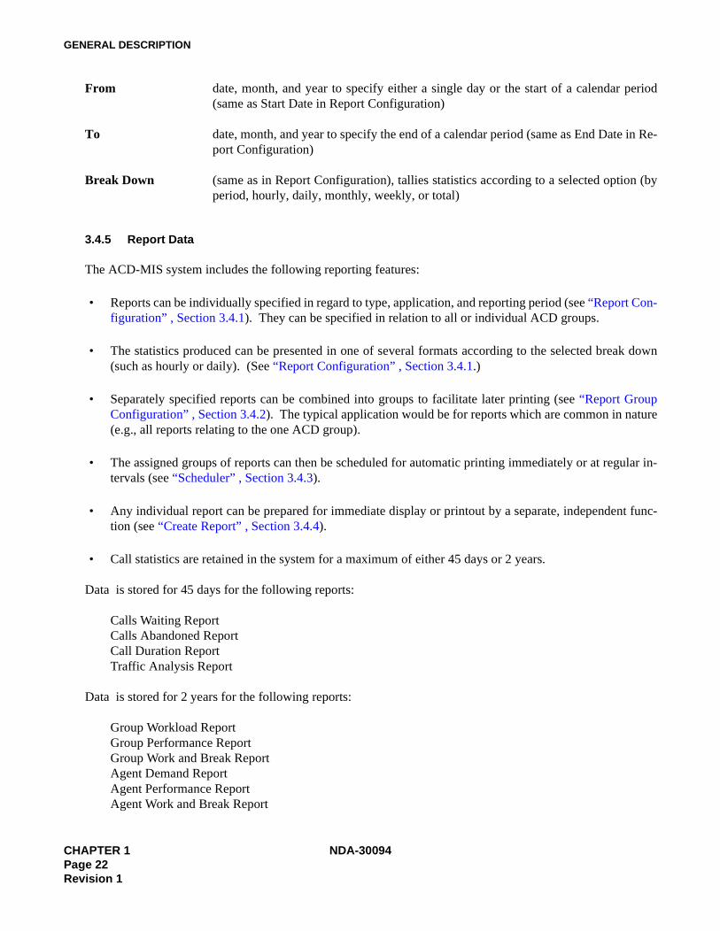
From date, month, and year to specify either a single day or the start of a calendar period(same as Start Date in Report Configuration)
To date, month, and year to specify the end of a calendar period (same as End Date in Re-port Configuration)
Break Down (same as in Report Configuration), tallies statistics according to a selected option (byperiod, hourly, daily, monthly, weekly, or total)
3.4.5 Report Data
The ACD-MIS system includes the following reporting features:
• Reports can be individually specified in regard to type, application, and reporting period (see “Report Con-figuration” , Section 3.4.1). They can be specified in relation to all or individual ACD groups.
• The statistics produced can be presented in one of several formats according to the selected break down(such as hourly or daily). (See “Report Configuration” , Section 3.4.1.)
• Separately specified reports can be combined into groups to facilitate later printing (see “Report GroupConfiguration” , Section 3.4.2). The typical application would be for reports which are common in nature(e.g., all reports relating to the one ACD group).
• The assigned groups of reports can then be scheduled for automatic printing immediately or at regular in-tervals (see “Scheduler” , Section 3.4.3).
• Any individual report can be prepared for immediate display or printout by a separate, independent func-tion (see “Create Report” , Section 3.4.4).
• Call statistics are retained in the system for a maximum of either 45 days or 2 years.
Data is stored for 45 days for the following reports:
Calls Waiting ReportCalls Abandoned ReportCall Duration ReportTraffic Analysis Report
Data is stored for 2 years for the following reports:
Group Workload ReportGroup Performance ReportGroup Work and Break ReportAgent Demand ReportAgent Performance ReportAgent Work and Break Report
CHAPTER 1 NDA-30094Page 22Revision 1
GENERAL DESCRIPTION
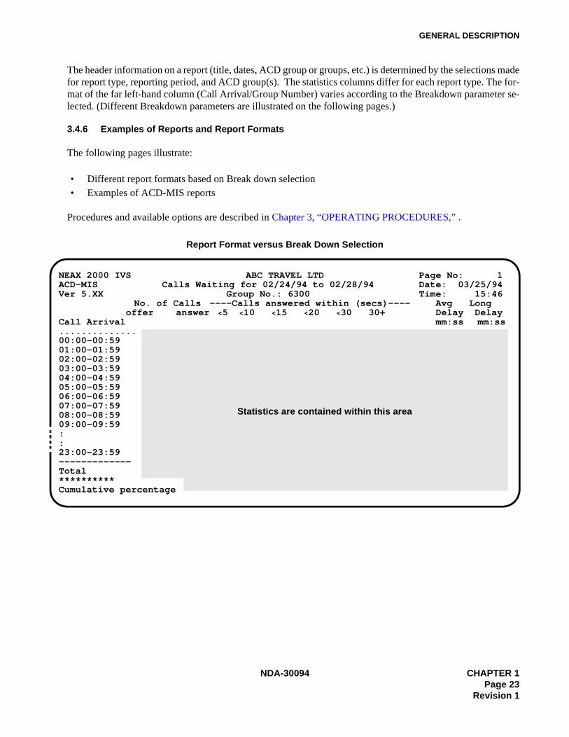
The header information on a report (title, dates, ACD group or groups, etc.) is determined by the selections madefor report type, reporting period, and ACD group(s). The statistics columns differ for each report type. The for-mat of the far left-hand column (Call Arrival/Group Number) varies according to the Breakdown parameter se-lected. (Different Breakdown parameters are illustrated on the following pages.)
3.4.6 Examples of Reports and Report Formats
The following pages illustrate:
• Different report formats based on Break down selection• Examples of ACD-MIS reports
Procedures and available options are described in Chapter 3, “OPERATING PROCEDURES,” .
Report Format versus Break Down Selection
NEAX 2000 IVS ABC TRAVEL LTD Page No: 1ACD-MIS Calls Waiting for 02/24/94 to 02/28/94 Date: 03/25/94Ver 5.XX Group No.: 6300 Time: 15:46
No. of Calls ----Calls answered within (secs)---- Avg Longoffer answer <5 <10 <15 <20 <30 30+ Delay Delay
Call Arrival mm:ss mm:ss..............00:00-00:5901:00-01:5902:00-02:5903:00-03:5904:00-04:5905:00-05:5906:00-06:5907:00-07:5908:00-08:5909:00-09:59::23:00-23:59-------------Total**********Cumulative percentage
Statistics are contained within this area
NDA-30094 CHAPTER 1Page 23
Revision 1
GENERAL DESCRIPTION
Break down = Hourly
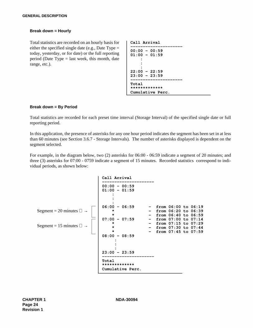
Break down = By Period
Total statistics are recorded for each preset time interval (Storage Interval) of the specified single date or fullreporting period.
In this application, the presence of asterisks for any one hour period indicates the segment has been set in at lessthan 60 minutes (see Section 3.6.7 - Storage Intervals). The number of asterisks displayed is dependent on thesegment selected.
For example, in the diagram below, two (2) asterisks for 06:00 - 06:59 indicate a segment of 20 minutes; andthree (3) asterisks for 07:00 - 0759 indicate a segment of 15 minutes. Recorded statistics correspond to indi-vidual periods, as shown below:
Call Arrival---------------------00:00 - 00:5901:00 - 01:59 : : :22:00 - 22:5923:00 - 23:59---------------------Total*************Cumulative Perc.
Total statistics are recorded on an hourly basis foreither the specified single date (e.g., Date Type =today, yesterday, or for date) or the full reportingperiod (Date Type = last week, this month, daterange, etc.).
Call Arrival---------------------00:00 - 00:5901:00 - 01:59 : : :06:00 - 06:59 - from 06:00 to 06:19 * - from 06:20 to 06:39 * - from 06:40 to 06:5907:00 - 07:59 - from 07:00 to 07:14 * - from 07:15 to 07:29 * - from 07:30 to 07:44 * - from 07:45 to 07:5908:00 - 08:59 : : :23:00 - 23:59---------------------Total*************Cumulative Perc.
Segment = 20 minutes →
Segment = 15 minutes →
CHAPTER 1 NDA-30094Page 24Revision 1
GENERAL DESCRIPTION
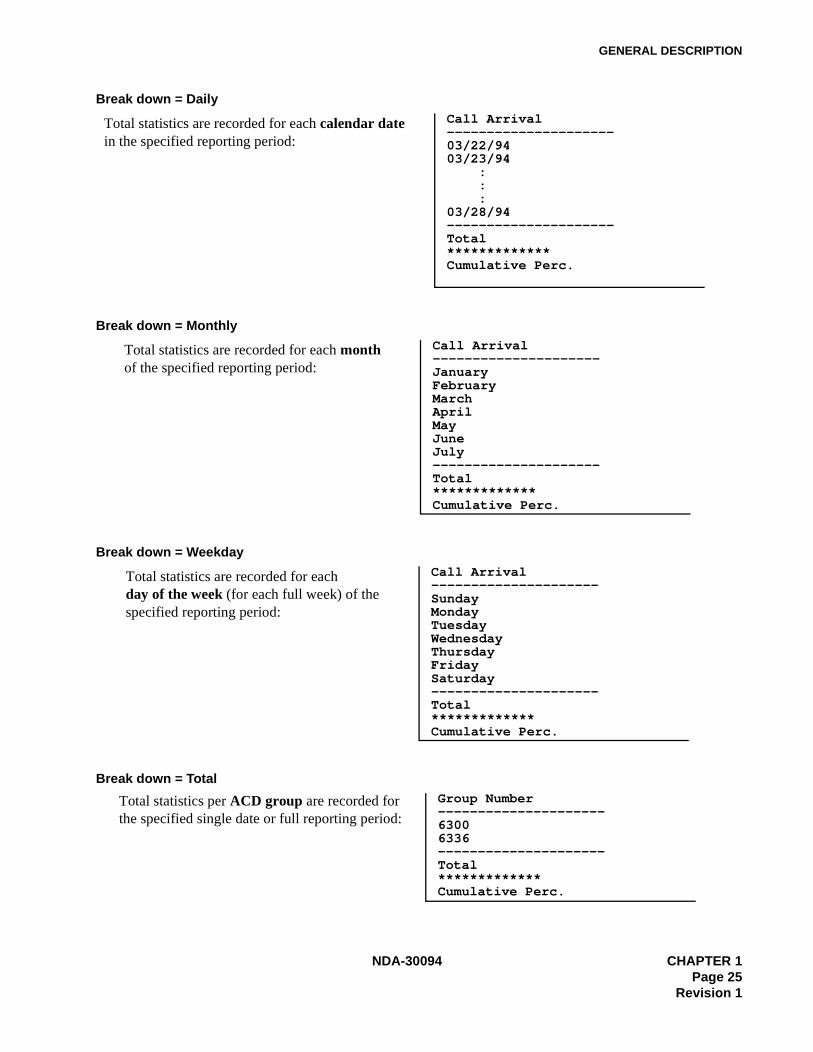
Break down = Daily
Break down = Monthly
Break down = Weekday
Break down = Total
Call Arrival---------------------03/22/9403/23/94 : : :03/28/94---------------------Total*************Cumulative Perc.
Total statistics are recorded for each calendar date in the specified reporting period:
Call Arrival---------------------JanuaryFebruaryMarchAprilMayJuneJuly---------------------Total*************Cumulative Perc.
Total statistics are recorded for each monthof the specified reporting period:
Call Arrival---------------------SundayMondayTuesdayWednesdayThursdayFridaySaturday---------------------Total*************Cumulative Perc.
Total statistics are recorded for eachday of the week (for each full week) of the specified reporting period:
Group Number---------------------63006336---------------------Total*************Cumulative Perc.
Total statistics per ACD group are recorded for the specified single date or full reporting period:
NDA-30094 CHAPTER 1Page 25
Revision 1
GENERAL DESCRIPTION
Calls Waiting Report
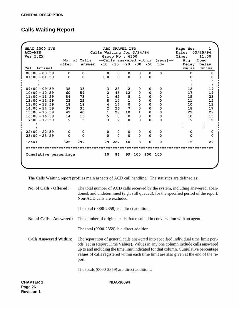
The Calls Waiting report profiles main aspects of ACD call handling. The statistics are defined as:
No. of Calls - Offered: The total number of ACD calls received by the system, including answered, aban-doned, and undetermined (e.g., still queued), for the specified period of the report.Non-ACD calls are excluded.
The total (0000-2359) is a direct addition.
No. of Calls - Answered: The number of original calls that resulted in conversation with an agent.
The total (0000-2359) is a direct addition.
Calls Answered Within: The separation of general calls answered into specified individual time limit peri-ods (set in Report Time Values). Values in any one column include calls answeredup to and including the time limit indicated for that column. Cumulative percentagevalues of calls registered within each time limit are also given at the end of the re-port.
The totals (0000-2359) are direct additions.
NEAX 2000 IVS ABC TRAVEL LTD Page No: 1ACD-MIS Calls Waiting for 3/24/94 Date: 03/25/94Ver 5.XX Group No.: 6300 Time: 11:00
No. of Calls --Calls answered within (secs)-- Avg Longoffer answer <10 <15 <20 <30 <50 50+ Delay Delay
Call Arrival mm:ss mm:ss00:00 - 00:5901:00 - 01:59 : :09:00 - 09:5910:00 - 10:5911:00 - 11:5912:00 - 12:5913:00 - 13:5914:00 - 14:5915:00 - 15:5916:00 - 16:5917:00 - 17:59 : :22:00 - 22:5923:00 - 23:59
0 00 0
38 3360 5984 7323 2318 1837 3542 4014 139 5
0 00 0
0 0 0 0 0 00 0 0 0 0 0
::
3 28 2 0 0 02 45 12 0 0 01 62 8 2 0 08 14 1 0 0 04 14 0 0 0 02 26 7 0 0 01 28 10 1 0 05 8 0 0 0 03 2 0 0 0 0
::
0 0 0 0 0 00 0 0 0 0 0
00::
121715111018221019
: :
00
00::
191923151317291312
::
00
Total 325 299 29 227 40 3 0 0 15 29
********************************************************************************
Cumulative percentage 10 86 99 100 100 100
CHAPTER 1 NDA-30094Page 26Revision 1

GENERAL DESCRIPTION
Average Delay: The average waiting time of ACD calls which are either in the queue or ringing agents,calculated as:
Total delay for the period Total calls offered for the period
The total (0000-2359) is calculated as:
Total delay for the system Total calls offered for the day
Longest Delay: The maximum time taken to answer any ACD call, either while queued or ringing anagent.
The total is the highest recorded value for the whole reporting period.
NDA-30094 CHAPTER 1Page 27
Revision 1

GENERAL DESCRIPTION
Calls Abandoned Report
mm:ss = minutes and seconds
The Calls Abandoned report is an analysis of received calls that were disconnected by the callers before an agentbecame available. Statistics are defined as follows:
No. of Calls - Offered: The total number of ACD calls received by the system, including answered, aban-doned, and undetermined (e.g., still queued), for the specified period of the report.Non-ACD calls are excluded.
The total (0000-2359) is a direct addition.
No. of Calls - Abandoned: The number of calls where the caller disconnected while queued or ringing anagent.
The total (0000-2359) is a direct addition.
NEAX 2000 IVS ABC TRAVEL LTD Page No: 1ACD-MIS Calls Abandoned for 3/24/94 Date: 03/25/94Ver 5.XX Group No.: 6300 Time: 11:00
No. of Calls -Calls abandoned within (secs)- Avg Longoffer abandn <5 <10 <15 <20 <50 50+ Delay Delay
Call Arrival mm:ss mm:ss00:00 - 00:5901:00 - 01:59
::
09:00 - 09:5910:00 - 10:5911:00 - 11:5912:00 - 12:5913:00 - 13:5914:00 - 14:5915:00 - 15:5916:00 - 16:5917:00 - 17:59
::
22:00 - 22:5923:00 - 23:59
0 00 0
38 560 184 1123 018 037 242 214 19 4
0 00 0
0 0 0 0 0 00 0 0 0 0 0
::
2 2 1 0 0 01 0 0 0 0 01 3 4 2 1 00 0 0 0 0 00 0 0 0 0 00 1 1 0 0 00 1 1 0 0 00 1 0 0 0 02 2 0 0 0 0
::
0 0 0 0 0 00 0 0 0 0 0
00::
08041400
09110808::00
00::
13043100
12140809::00
Total 325 26 6 10 7 2 1 0 11 31
********************************************************************************
Cumulative percentage 23 61 88 96 100 100
CHAPTER 1 NDA-30094Page 28Revision 1
GENERAL DESCRIPTION
Calls Abandoned Within: The separation of general calls abandoned into specified individual time limit pe-riods (set in Report Time Values). Values in any one column include calls aban-doned up to and including the time limit indicated for that column. Cumulativepercentage values of calls registered within each time limit are also given at the endof the report.
The totals (0000-2359) are direct additions.
Average Delay: Average waiting time before disconnection by callers, either from the queue orwhile ringing an agent, calculated as:
Total queue time + total ring time Total calls abandoned for the period
The total (0000-2359) is calculated as:
Total waiting time for the system Total calls abandoned for the day
Longest Delay: The longest time before abandonment of any call that is queued or ringing an agent.
The total is the highest recorded value for the whole reporting period.
NDA-30094 CHAPTER 1Page 29
Revision 1
GENERAL DESCRIPTION
Call Duration Report
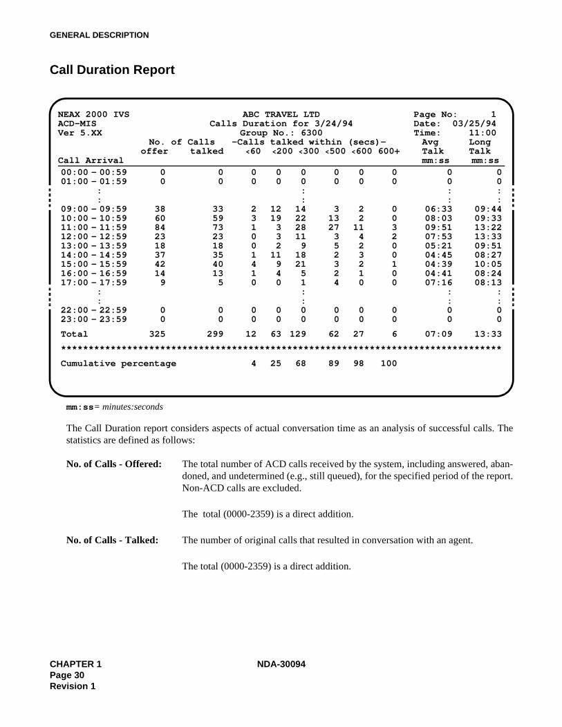
mm:ss= minutes:seconds
The Call Duration report considers aspects of actual conversation time as an analysis of successful calls. Thestatistics are defined as follows:
No. of Calls - Offered: The total number of ACD calls received by the system, including answered, aban-doned, and undetermined (e.g., still queued), for the specified period of the report.Non-ACD calls are excluded.
The total (0000-2359) is a direct addition.
No. of Calls - Talked: The number of original calls that resulted in conversation with an agent.
The total (0000-2359) is a direct addition.
NEAX 2000 IVS ABC TRAVEL LTD Page No: 1ACD-MIS Calls Duration for 3/24/94 Date: 03/25/94Ver 5.XX Group No.: 6300 Time: 11:00
No. of Calls -Calls talked within (secs)- Avg Longoffer talked <60 <200 <300 <500 <600 600+ Talk Talk
Call Arrival mm:ss mm:ss00:00 - 00:5901:00 - 01:59
::
09:00 - 09:5910:00 - 10:5911:00 - 11:5912:00 - 12:5913:00 - 13:5914:00 - 14:5915:00 - 15:5916:00 - 16:5917:00 - 17:59
::
22:00 - 22:5923:00 - 23:59
0 00 0
38 3360 5984 7323 2318 1837 3542 4014 139 5
0 00 0
0 0 0 0 0 00 0 0 0 0 0
::
2 12 14 3 2 03 19 22 13 2 01 3 28 27 11 30 3 11 3 4 20 2 9 5 2 01 11 18 2 3 04 9 21 3 2 11 4 5 2 1 00 0 1 4 0 0
::
0 0 0 0 0 00 0 0 0 0 0
00::
06:3308:0309:5107:5305:2104:4504:3904:4107:16
::00
00::
09:4409:3313:2213:3309:5108:2710:0508:2408:13
::00
Total 325 299 12 63 129 62 27 6 07:09 13:33
********************************************************************************
Cumulative percentage 4 25 68 89 98 100
CHAPTER 1 NDA-30094Page 30Revision 1
GENERAL DESCRIPTION
Calls Talked Within: The breakdown of conversation times into specified individual time periods (set inReport Time Values).
Values in any one column include call durations up to and including the limit indi-cated for that column. Cumulative percentage values of calls registered within eachperiod are also given at the end of the report.
The totals (0000-2359) are direct additions.
Average Talk: The average conversation time for all answered calls, calculated as:
Total duration time for the period Total calls answered for the period
The total (0000-2359) is calculated as:
Total duration time for the system Total calls answered for the day
Longest Talk: The maximum conversation time of any answered call.
The total is the highest recorded value for the whole reporting period.
NDA-30094 CHAPTER 1Page 31
Revision 1
GENERAL DESCRIPTION
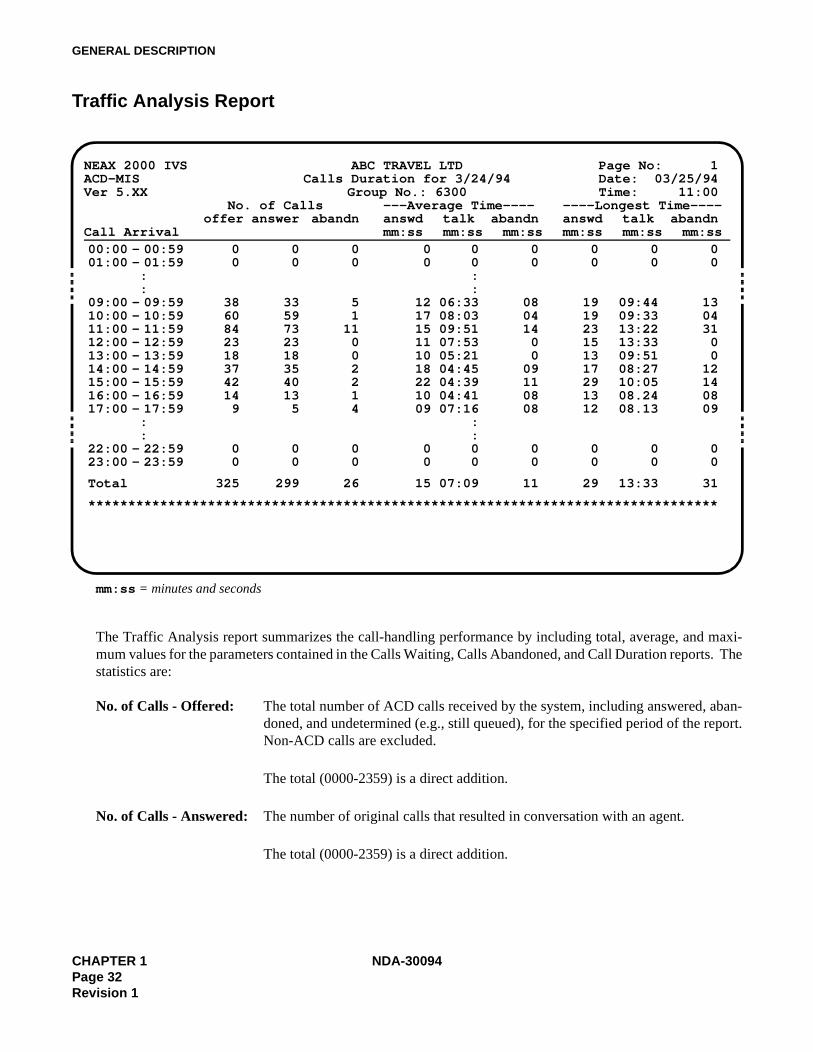
Traffic Analysis Report
mm:ss = minutes and seconds
The Traffic Analysis report summarizes the call-handling performance by including total, average, and maxi-mum values for the parameters contained in the Calls Waiting, Calls Abandoned, and Call Duration reports. Thestatistics are:
No. of Calls - Offered: The total number of ACD calls received by the system, including answered, aban-doned, and undetermined (e.g., still queued), for the specified period of the report.Non-ACD calls are excluded.
The total (0000-2359) is a direct addition.
No. of Calls - Answered: The number of original calls that resulted in conversation with an agent.
The total (0000-2359) is a direct addition.
NEAX 2000 IVS ABC TRAVEL LTD Page No: 1ACD-MIS Calls Duration for 3/24/94 Date: 03/25/94Ver 5.XX Group No.: 6300 Time: 11:00
No. of Calls ---Average Time---- ----Longest Time----offer answer abandn answd talk abandn answd talk abandn
Call Arrival mm:ss mm:ss mm:ss mm:ss mm:ss mm:ss00:00 - 00:5901:00 - 01:59
::
09:00 - 09:5910:00 - 10:5911:00 - 11:5912:00 - 12:5913:00 - 13:5914:00 - 14:5915:00 - 15:5916:00 - 16:5917:00 - 17:59
::
22:00 - 22:5923:00 - 23:59
0 0 00 0 0
38 33 560 59 184 73 1123 23 018 18 037 35 242 40 214 13 19 5 4
0 0 00 0 0
0 0 00 0 0
::
12 06:33 0817 08:03 0415 09:51 1411 07:53 010 05:21 018 04:45 0922 04:39 1110 04:41 0809 07:16 08
::
0 0 00 0 0
0 0 00 0 0
19 09:44 1319 09:33 0423 13:22 3115 13:33 013 09:51 017 08:27 1229 10:05 1413 08.24 0812 08.13 09
0 0 00 0 0
Total 325 299 26 15 07:09 11 29 13:33 31
*******************************************************************************
CHAPTER 1 NDA-30094Page 32Revision 1

GENERAL DESCRIPTION
No. of Calls - Abandoned: The number of calls where the caller disconnected while queued or ringing anagent.
The total (0000-2359) is a direct addition.
Average Time Answered: The average waiting time between ringing an agent and start of conversation for allcalls answered, calculated as:
Total waiting time for the period Total calls answered for the period
The total (0000-2359) is calculated as:
Total waiting time for the systemTotal calls answered for the day
Average Time Talk: The average conversation time of all calls answered, calculated as:
Total conversation time for the period Total calls answered for the period
The total (0000-2359) is calculated as:
Total conversation time for the system Total calls answered for the day
Average Time Abandon: Average waiting time before disconnection by the caller while either queued orringing an agent, calculated as:
Total waiting time for the period Total calls abandoned for the period
The summary total (0000-2359) is calculated as:
Total waiting time for the system Total calls abandoned for the day
Longest Time Answered: The longest waiting time before start of conversation of any call ringing an agent.
The total is the highest recorded value for the whole reporting period.
Longest Time Talk: The longest conversation time of any calls answered.
The total is the highest recorded value for the whole reporting period.
NDA-30094 CHAPTER 1Page 33
Revision 1

GENERAL DESCRIPTION
Longest Time Abandon: The longest waiting time before disconnection of any calls abandoned.
The total is the highest recorded value for the whole reporting period.
CHAPTER 1 NDA-30094Page 34Revision 1
GENERAL DESCRIPTION
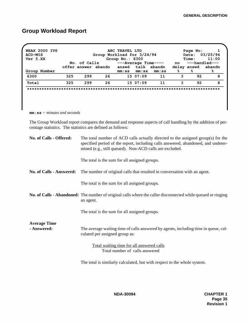
Group Workload Report
mm:ss = minutes and seconds
The Group Workload report compares the demand and response aspects of call handling by the addition of per-centage statistics. The statistics are defined as follows:
No. of Calls - Offered: The total number of ACD calls actually directed to the assigned group(s) for thespecified period of the report, including calls answered, abandoned, and undeter-mined (e.g., still queued). Non-ACD calls are excluded.
The total is the sum for all assigned groups.
No. of Calls - Answered: The number of original calls that resulted in conversation with an agent.
The total is the sum for all assigned groups.
No. of Calls - Abandoned: The number of original calls where the caller disconnected while queued or ringingan agent.
The total is the sum for all assigned groups.
Average Time- Answered: The average waiting time of calls answered by agents, including time in queue, cal-
culated per assigned group as:
Total waiting time for all answered calls Total number of calls answered
The total is similarly calculated, but with respect to the whole system.
NEAX 2000 IVS ABC TRAVEL LTD Page No: 1ACD-MIS Group Workload for 3/24/94 Date: 03/25/94Ver 5.XX Group No.: 6300 Time: 11:00
No. of Calls ---Average Time---- no ---handled---offer answer abandn answd talk abandn delay answd abandn
Group Number mm:ss mm:ss mm:ss % % %6300 325 299 26 15 07:09 11 3 92 8
Total 325 299 26 15 07:09 11 3 92 8
*******************************************************************************
NDA-30094 CHAPTER 1Page 35
Revision 1
GENERAL DESCRIPTION
Average Time - Talk: The average conversation time of the calls answered by agents, calculated per as-signed group as:
Total conversation time Total number of calls terminated after conversation
The total is similarly calculated, but with respect to the whole system.
Average Time- Abandoned: The average waiting time of calls that were disconnected by the caller while in the
queue and/or ringing an agent, calculated per assigned group as:
Total waiting time for all abandoned calls Total number of calls abandoned
The total is similarly calculated, but with respect to the whole system.
No Delay %: The percentage of calls answered without being queued, calculated per assignedgroup as:
Total number of calls answered directly by agents x 100 Total number of answered and abandoned calls
The total is similarly calculated, but with respect to the whole system.
% Handled - Answered: The percentage of calls that were eventually answered by agents, either with orwithout delay, calculated per assigned group as:
Total number of calls answered by agents x 100 Total number of calls originally offered
The total is similarly calculated, but with respect to the whole system.
% Handled - Abandoned: The percentage of calls that were disconnected by the caller, either while in thequeue or ringing an agent, calculated per assigned group as:
Total number of calls disconnected by callers x 100 Total number of calls originally offered
The total is similarly calculated, but with respect to the whole system.
CHAPTER 1 NDA-30094Page 36Revision 1

GENERAL DESCRIPTION
Group Performance Report
hh:mm:ss = hours, minutes and seconds
The Group Performance report compares occupancy on non-ACD and ACD calls and idle (available) mode forthe specified ACD group(s). The relevant statistics are:
No. of Calls - ACD: The total number of ACD calls directed to the assigned group(s) for the specifiedperiod of the report, including calls answered, abandoned, and undetermined (e.g.,still queued). Non-ACD calls are excluded.
The total is the sum for all assigned groups.
No. of Calls - NACD: For the specified period of the report, the total number of non-ACD calls (eitheranswered or abandoned) directed to agents in the assigned group(s), but only whilein the AVAILABLE status.
The total is the sum for all assigned groups.
NEAX 2000 IVS ABC TRAVEL LTD Page No: 1ACD-MIS Group Performance for 3/24/94 Date: 03/25/94Ver 5.XX Group No.: 6300 Time: 11:00
No. of Calls ---Average Time---- ----Total Time----ACD NACD ACD NACD AVAIL ACD NACD AVAIL
Group Number mm:ss mm:ss mm:ss hh:mm hh:mm hh:mm6300 325 84 07:09 03:59 01:03 35:37 11:06 12
Total 325 84 07:09 03:59 01:03 35:37 11:06 12
*******************************************************************************
NDA-30094 CHAPTER 1Page 37
Revision 1

GENERAL DESCRIPTION
Average Time - ACD: The average conversation time for all ACD calls which were answered, calculatedper assigned group as:
Total conversation time on ACD callsTotal number of ACD calls answered
The total is similarly calculated, but with respect to the whole system.
Average Time - NACD: The average conversation time on non-ACD calls that were answered, calculatedper ACD group as:
Total conversation time on non-ACD callsTotal number of answered non-ACD calls
The total is similarly calculated, but with respect to the whole system.
Average Time - Available: The average waiting time between both ACD and non-ACD calls, but only whilelogged on, calculated per assigned group as:
Total time agents wait for (non-)ACD calls Total occasions agents available and logged on
The total is similarly calculated, but with respect to the whole system.
Total Time - ACD: The total conversation time on ACD calls that were answered.
The total is the sum for all assigned groups.
Total Time - NACD: The total conversation time on non-ACD calls that were answered.
The total is the sum for all assigned groups.
Total Time - Available: The total time agents spent waiting between both ACD and non-ACD calls, butonly while logged on.
The total is the sum for all assigned groups.
CHAPTER 1 NDA-30094Page 38Revision 1
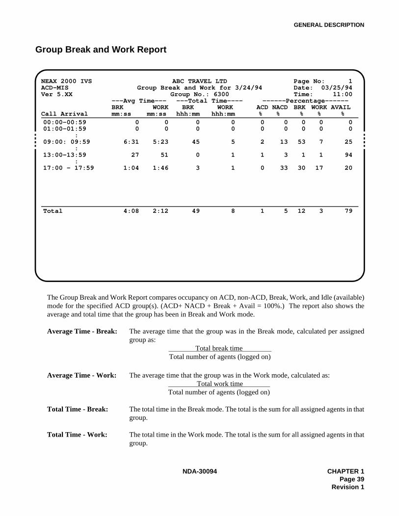
GENERAL DESCRIPTION
Group Break and Work Report
The Group Break and Work Report compares occupancy on ACD, non-ACD, Break, Work, and Idle (available)mode for the specified ACD group(s). (ACD+ NACD + Break + Avail = 100%.) The report also shows theaverage and total time that the group has been in Break and Work mode.
Average Time - Break: The average time that the group was in the Break mode, calculated per assignedgroup as:
Total break time Total number of agents (logged on)
Average Time - Work: The average time that the group was in the Work mode, calculated as: Total work time
Total number of agents (logged on)
Total Time - Break: The total time in the Break mode. The total is the sum for all assigned agents in thatgroup.
Total Time - Work: The total time in the Work mode. The total is the sum for all assigned agents in thatgroup.
NEAX 2000 IVS ABC TRAVEL LTD Page No: 1ACD-MIS Group Break and Work for 3/24/94 Date: 03/25/94Ver 5.XX Group No.: 6300 Time: 11:00
---Avg Time--- ---Total Time---- ------Percentage------BRK WORK BRK WORK ACD NACD BRK WORK AVAIL
Call Arrival mm:ss mm:ss hhh:mm hhh:mm % % % % %00:00-00:5901:00-01:59
:09:00: 09:59
:13:00-13:59
:17:00 - 17:59
00
6:31
27
1:04
00
5:23
51
1:46
0 00 0
45 5
0 1
3 1
0 0 00 0 0
2 13 53
1 3 1
0 33 30
0 00 0
7 25
1 94
17 20
Total 4:08 2:12 49 8 1 5 12 3 79
NDA-30094 CHAPTER 1Page 39
Revision 1

GENERAL DESCRIPTION
Percentage ACD: The percentage of time that the group spent on ACD calls.
Percentage NACD: The percentage of time that the group spent on non-ACD calls.
Percentage Break: The percentage of time that the agents of the specified group were in Break mode.
Percentage Work: The percentage of time that the agents of the specified group were in Work mode.
Percentage Avail: The percentage of time that the agents of the specified group were idle (available).
CHAPTER 1 NDA-30094Page 40Revision 1
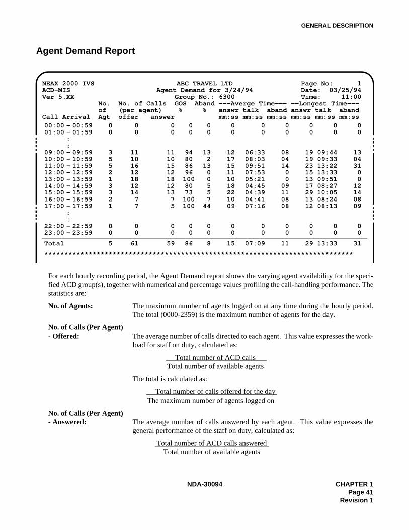
GENERAL DESCRIPTION
Agent Demand Report
For each hourly recording period, the Agent Demand report shows the varying agent availability for the speci-fied ACD group(s), together with numerical and percentage values profiling the call-handling performance. Thestatistics are:
No. of Agents: The maximum number of agents logged on at any time during the hourly period.The total (0000-2359) is the maximum number of agents for the day.
No. of Calls (Per Agent)- Offered: The average number of calls directed to each agent. This value expresses the work-
load for staff on duty, calculated as:
Total number of ACD calls Total number of available agents
The total is calculated as:
Total number of calls offered for the day The maximum number of agents logged on
No. of Calls (Per Agent)- Answered: The average number of calls answered by each agent. This value expresses the
general performance of the staff on duty, calculated as:
Total number of ACD calls answered Total number of available agents
NEAX 2000 IVS ABC TRAVEL LTD Page No: 1ACD-MIS Agent Demand for 3/24/94 Date: 03/25/94Ver 5.XX Group No.: 6300 Time: 11:00 No. No. of Calls GOS Aband ---Averge Time--- --Longest Time--- of (per agent) % % answr talk aband answr talk abandCall Arrival Agt offer answer mm:ss mm:ss mm:ss mm:ss mm:ss mm:ss00:00 - 00:5901:00 - 01:59
::
09:00 - 09:5910:00 - 10:5911:00 - 11:5912:00 - 12:5913:00 - 13:5914:00 - 14:5915:00 - 15:5916:00 - 16:5917:00 - 17:59
::
22:00 - 22:5923:00 - 23:59
00
355213321
00
0 00 0
11 1110 1016 1512 1218 1812 1214 137 77 5
0 00 0
0 00 0
94 1380 286 1396 0100 080 573 5100 7100 44
0 00 0
0 0 00 0 0
12 06:33 0817 08:03 0415 09:51 1411 07:53 010 05:21 018 04:45 0922 04:39 1110 04:41 0809 07:16 08
0 0 00 0 0
0 0 00 0 0
19 09:44 1319 09:33 0423 13:22 3115 13:33 013 09:51 017 08:27 1229 10:05 1413 08:24 0812 08:13 09
0 0 00 0 0
Total 5 61 59 86 8 15 07:09 11 29 13:33 31
*****************************************************************************
NDA-30094 CHAPTER 1Page 41
Revision 1

GENERAL DESCRIPTION
The total is calculated as:
Total number of calls answered for the day The maximum number of agents logged on
GOS %: The percentage of ACD calls answered within the x-seconds time limit for the sys-tem’s Grade of Service (set in Report Time Values), calculated as:
Total number of calls answered in x seconds x 100Total number of calls answered for the period
The total is the GOS for the day.
Abandoned %: The percentage of all received ACD calls that were disconnected by the callerswhile queued or ringing agent, calculated as:
Total number of calls abandoned x 100Total number of calls received for the period
The total is the average for the day.
Average Time- Answered: The average waiting time before calls were answered, including time in queue, cal-
culated as:
Total waiting time for all answered calls Total number of calls answered
The total is similarly calculated, but with respect to the whole system.
Average Time - Talk: The average conversation time for answered calls, calculated as:
Total conversation time Total number of calls terminated after conversation
The total is similarly calculated, but with respect to the whole system.
Average Time- Abandoned: The average waiting time of calls that were disconnected by the caller while in the
queue and/or ringing an agent, calculated as:
Total waiting time for all abandoned calls Total number of calls abandoned
The total is similarly calculated, but with respect to the whole system.
Longest Time- Answered: The longest waiting time before start of conversation of any call ringing an agent.
The total is the highest value recorded in the report.
Longest Time - Talk: The longest conversation time of any answered call. The total is the highest valuerecorded in the report.
Longest Time- Abandoned: The longest waiting time before disconnection of any abandoned call. The total is
the highest value recorded in the report.
CHAPTER 1 NDA-30094Page 42Revision 1
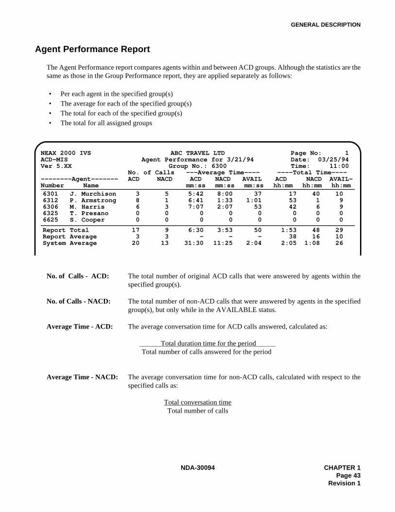
GENERAL DESCRIPTION
Agent Performance Report
The Agent Performance report compares agents within and between ACD groups. Although the statistics are thesame as those in the Group Performance report, they are applied separately as follows:
• Per each agent in the specified group(s)• The average for each of the specified group(s)• The total for each of the specified group(s)• The total for all assigned groups
No. of Calls - ACD: The total number of original ACD calls that were answered by agents within thespecified group(s).
No. of Calls - NACD: The total number of non-ACD calls that were answered by agents in the specifiedgroup(s), but only while in the AVAILABLE status.
Average Time - ACD: The average conversation time for ACD calls answered, calculated as:
Total duration time for the period Total number of calls answered for the period
Average Time - NACD: The average conversation time for non-ACD calls, calculated with respect to thespecified calls as:
Total conversation timeTotal number of calls
NEAX 2000 IVS ABC TRAVEL LTD Page No: 1ACD-MIS Agent Performance for 3/21/94 Date: 03/25/94Ver 5.XX Group No.: 6300 Time: 11:00
No. of Calls ---Average Time---- ----Total Time------------Agent------- ACD NACD ACD NACD AVAIL ACD NACD AVAIL-Number Name mm:ss mm:ss mm:ss hh:mm hh:mm hh:mm6301 J. Murchison6312 P. Armstrong6306 M. Harris6325 T. Presano6625 S. Cooper
3 58 16 30 00 0
5:42 8:00 376:41 1:33 1:017:07 2:07 53
0 0 00 0 0
17 40 1053 1 942 6 90 0 00 0 0
Report TotalReport AverageSystem Average
17 93 3
20 13
6:30 3:53 50- - -
31:30 11:25 2:04
1:53 48 2938 16 10
2:05 1:08 26
NDA-30094 CHAPTER 1Page 43
Revision 1

GENERAL DESCRIPTION
Average Time - Available: The average waiting time between both ACD and non-ACD calls, only whilelogged on, calculated as:
Amount of time agents wait for both ACD and non-ACD calls Total occasions agents available and logged on
Total Time - ACD: The total conversation time for ACD calls.
Total Time - NACD: The total conversation time for non-ACD calls.
Total Time - Available: The total time agents spent waiting between both ACD and non-ACD calls, onlywhile logged on.
Report Average
These per-agent values are calculated on the basis of the actual total complement of agents assigned to the ACDgroup, not only the number available or logged on, generally calculated as:
Total value for the group Total number of assigned agents
No. of Calls - ACD: Direct calculation using the formula above.
No. of Calls - NACD: Direct calculation using the formula above.
Average Time - ACD, These statistics have no real meaning (i.e., averages of averages). NACD, and Available: All reports will show blanks in these areas.
Total Time - ACD, NACD, and Available: Direct calculations using the formula above.
Report Total and System Average
No. of Calls - ACD and NACD: By direct additions of the per-agent values.
Average Time - ACD, NACD, and Available: The general formula is:
Total conversation or available time for the group Total number of calls handled or times available in the group
Total Time - ACD, By direct additions of the per-agent values. NACD, and Available:
CHAPTER 1 NDA-30094Page 44Revision 1
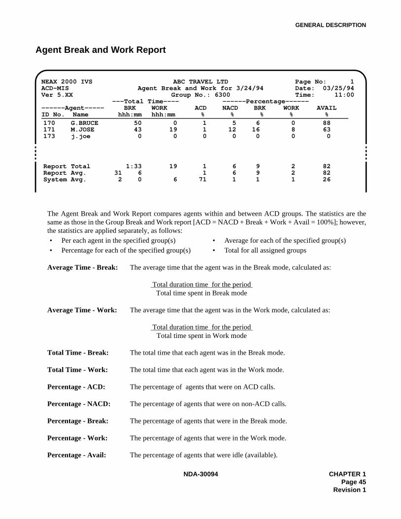
GENERAL DESCRIPTION
Agent Break and Work Report
The Agent Break and Work Report compares agents within and between ACD groups. The statistics are thesame as those in the Group Break and Work report [ACD = NACD + Break + Work + Avail = 100%]; however,the statistics are applied separately, as follows:• Per each agent in the specified group(s) • Average for each of the specified group(s)• Percentage for each of the specified group(s) • Total for all assigned groups
Average Time - Break: The average time that the agent was in the Break mode, calculated as:
Total duration time for the period Total time spent in Break mode
Average Time - Work: The average time that the agent was in the Work mode, calculated as:
Total duration time for the period Total time spent in Work mode
Total Time - Break: The total time that each agent was in the Break mode.
Total Time - Work: The total time that each agent was in the Work mode.
Percentage - ACD: The percentage of agents that were on ACD calls.
Percentage - NACD: The percentage of agents that were on non-ACD calls.
Percentage - Break: The percentage of agents that were in the Break mode.
Percentage - Work: The percentage of agents that were in the Work mode.
Percentage - Avail: The percentage of agents that were idle (available).
NEAX 2000 IVS ABC TRAVEL LTD Page No: 1ACD-MIS Agent Break and Work for 3/24/94 Date: 03/25/94Ver 5.XX Group No.: 6300 Time: 11:00
---Total Time---- ------Percentage------------Agent----- BRK WORK ACD NACD BRK WORK AVAILID No. Name hhh:mm hhh:mm % % % % %170 G.BRUCE171 M.JOSE173 j.joe
50 043 190 0
1 5 61 12 160 0 0
0 888 630 0
Report TotalReport Avg.System Avg.
1:33 1931 6 2 0 6
1 6 91 6 9
71 1 1
2 822 821 26
NDA-30094 CHAPTER 1Page 45
Revision 1
GENERAL DESCRIPTION
Report Average: These per-agent values are calculated on the basis of the actual complement ofagents assigned to the ACD group, not only the number available or logged on,generally calculated as:
Total value for the group Total number of assigned agents
Report Total and System Average: Report total is calculated by direct addition of the per-agent values. The system av-
erage is calculated with total number of agents in all groups.
CHAPTER 1 NDA-30094Page 46Revision 1

GENERAL DESCRIPTION
3.5 System Maintenance
This menu option covers system administration (such as password control, system back-up, alarm setting, etc.).This option includes eight submenus, which are described in the following sections:
“Password Maintenance” , Section 3.5.1“ACD Alarms” , Section 3.5.2“System Message” , Section 3.5.3“OAI Connection” , Section 3.5.4“EDU Port Selection” , Section 3.5.6 “External Display Format” , Section 3.5.7
3.5.1 Password Maintenance
The ACD-MIS system can accommodate a total of 12 passwords. Initially two are set in default data with thefollowing specifications:
• The first password (which corresponds to the Enter key) is set to considerably limit access to system fea-tures. This status can be altered if required.
• The second password is programmed for fixed, unrestricted access to all features. The original name is"mis" (in lowercase letters), which can be changed to one preferred by the user.
When setting the remaining passwords, limit each password to 10 alphabetical characters. Thereafter, the existing structure of a password can be added to or modified, within the limitations mentioned.
During normal use of the system, white represents permitted access to certain features or services; an amber col-or indicates that access is restricted.
3.5.2 ACD Alarms ACD-MIS lets you set limits on various statistics parameters. These are described in “Alarm Configuration” ,Section 3.7.
If any data is equal to or greater than a specified setting, the parameter will change color in the Statistics Monitordisplay.
If the screen is not in display mode at the particular time, a warning message will display (at the top of thescreen) to indicate the affected area (system, group or agent statistics) and the alarm level (urgent or non-urgent).If the longest waiting time statistic exceeds the maximum value, an audible alarm is given at a preset period.
All alarm occurrences are recorded to file that can be displayed or printed for a specified date.
NDA-30094 CHAPTER 1Page 47
Revision 1
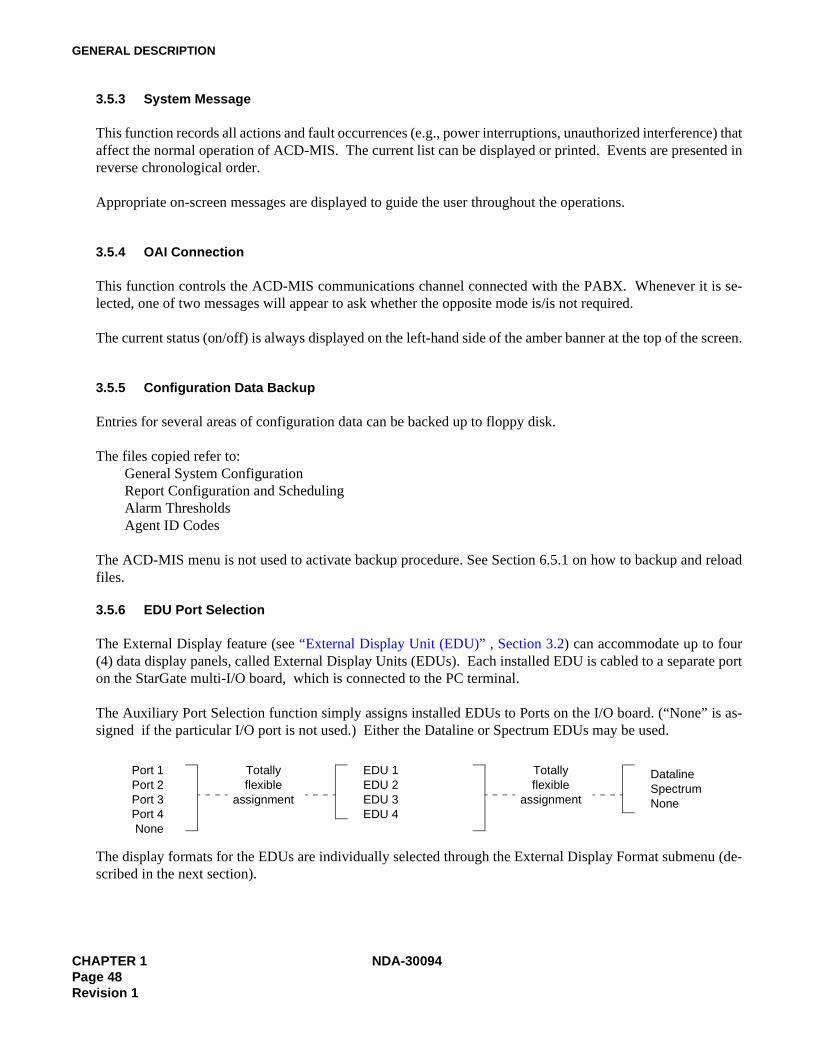
GENERAL DESCRIPTION
3.5.3 System Message
This function records all actions and fault occurrences (e.g., power interruptions, unauthorized interference) thataffect the normal operation of ACD-MIS. The current list can be displayed or printed. Events are presented inreverse chronological order.
Appropriate on-screen messages are displayed to guide the user throughout the operations.
3.5.4 OAI Connection
This function controls the ACD-MIS communications channel connected with the PABX. Whenever it is se-lected, one of two messages will appear to ask whether the opposite mode is/is not required.
The current status (on/off) is always displayed on the left-hand side of the amber banner at the top of the screen.
3.5.5 Configuration Data Backup
Entries for several areas of configuration data can be backed up to floppy disk.
The files copied refer to:General System ConfigurationReport Configuration and SchedulingAlarm ThresholdsAgent ID Codes
The ACD-MIS menu is not used to activate backup procedure. See Section 6.5.1 on how to backup and reloadfiles.
3.5.6 EDU Port Selection
The External Display feature (see “External Display Unit (EDU)” , Section 3.2) can accommodate up to four(4) data display panels, called External Display Units (EDUs). Each installed EDU is cabled to a separate porton the StarGate multi-I/O board, which is connected to the PC terminal.
The Auxiliary Port Selection function simply assigns installed EDUs to Ports on the I/O board. (“None” is as-signed if the particular I/O port is not used.) Either the Dataline or Spectrum EDUs may be used.
The display formats for the EDUs are individually selected through the External Display Format submenu (de-scribed in the next section).
Port 1Port 2Port 3Port 4None
Totallyflexible
assignment
EDU 1EDU 2EDU 3EDU 4
Totallyflexible
assignment
DatalineSpectrumNone
CHAPTER 1 NDA-30094Page 48Revision 1
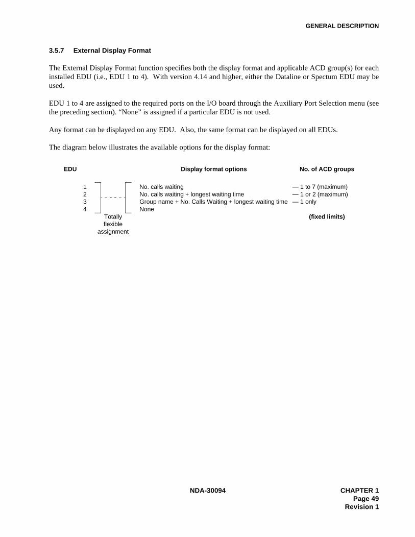
GENERAL DESCRIPTION
3.5.7 External Display Format
The External Display Format function specifies both the display format and applicable ACD group(s) for eachinstalled EDU (i.e., EDU 1 to 4). With version 4.14 and higher, either the Dataline or Spectum EDU may beused.
EDU 1 to 4 are assigned to the required ports on the I/O board through the Auxiliary Port Selection menu (seethe preceding section). “None” is assigned if a particular EDU is not used.
Any format can be displayed on any EDU. Also, the same format can be displayed on all EDUs.
The diagram below illustrates the available options for the display format:
EDU Display format options No. of ACD groups
1234
Totallyflexible
assignment
No. calls waitingNo. calls waiting + longest waiting timeGroup name + No. Calls Waiting + longest waiting timeNone
— 1 to 7 (maximum)— 1 or 2 (maximum)— 1 only
(fixed limits)
NDA-30094 CHAPTER 1Page 49
Revision 1
GENERAL DESCRIPTION
3.6 System Configuration
ACD-MIS’s System Configuration menu item lets you set up or modify the following:• System site name• ACD groups and their assigned agents• Various operational default parameters that affect the reporting functions
The System Configuration menu includes eight submenus, which are described in the following sections:
“System Name” , Section 3.6.1“Group Configuration” , Section 3.6.2“Station Configuration” , Section 3.6.3“Agent Configuration” , Section 3.6.4“ACD Key Configuration” , Section 3.6.5“Report Time Values” , Section 3.6.6“Storage Intervals” , Section 3.6.7“System Date Format” , Section 3.6.8
3.6.1 System Name
This function lets you program the preferred site name that displays on all screens. The same site name is in-cluded in the header information of report printouts.
Up to 40 characters can be specified for the selected name.
3.6.2 Group Configuration
This function lets you specify information about ACD groups. The ACD-MIS can accommodate up to 16 ACDgroups. For each group, the following details can be specified:• The selected name for the customer• The relevant indial prefix digits• The pilot extension number
Name and indial prefix are identical to assignments within the PABX itself; there must be an exact correspon-dence between the two systems.
Three different on-screen messages (New Group, In Use, and Not Used) indicate the status of each of the avail-able groups.
3.6.3 Station Configuration
There can be a maximum of 60 extensions per MIS system, in any combination of 16 ACD groups. Several de-tails can be assigned to identify each. Certain information (tenant number, telephone type, extension number,etc.) duplicates PABX programming and must correspond exactly.
CHAPTER 1 NDA-30094Page 50Revision 1

GENERAL DESCRIPTION
The separate items entered for each station are:
• Extension number• Tenant number • Type of telephone instrument (digital or analog) provided for each agent position or the classification as
specified in the PABX in the case of a pilot number• Associated ACD group number
Note: An assigned pilot extension does not appear on any screen displays or in any reports.
3.6.4 Agent Configuration
There can be a maximum of 90 agent ID codes per system, in any combination of 16 ACD groups. Several de-tails are assigned to identify each. Agent information is programmed only in the ACD-MIS, not in the PABX.
The separate items entered for each agent are:
• Agent ID• Name of the agent• Initial of the agent• Associated ACD group number
Note: The Agent ID is assigned to an ACD group and not to an ACD station.
3.6.5 ACD Key Configuration
This configures the required MSF number and the LED number for Log On/Off, Break, and Work. The MSFand LED numbers must be the same as those entered in CM90 of system programming. These two parametersare system parameters, so they cannot be different for each station.
NDA-30094 CHAPTER 1Page 51
Revision 1

GENERAL DESCRIPTION
3.6.6 Report Time Values
Report Time Values are time limits that are relevant to the Statistics Monitor mode (see “Statistics Monitor” ,Section 3.3) and Report Data (see “Report Data” , Section 3.4.5). Their individual applications are summarizedin Table 1-3.
3.6.7 Storage Intervals
Storage Intervals are specified individual call recording periods within each hour of the day. Their applicationis in the presentation of statistics for each of the following reports where the selected option for report break-down is set to “By Period.” • Calls Waiting Report• Calls Abandon Report• Call Duration Report• Traffic Analysis Report• Agent Demand Report• Group Break and Work Report• Agent Break and Work Report
Although initially set at one hour in the basic system data, storage intervals can be specified at more regularintervals of 10, 15, 20 and 30 minutes where required. Typically, storage interval settings are used to providemore frequent analysis during peak traffic periods.
Table 1-3 Report Time Values
Report time value Application
Time to Answer (GOS) Used in calculation of Grade of Service for the Statistics Monitor mode and the Agent Demand Report
Abandoned Ignore Time Minimum time a call which is disconnected by the caller before answer, must have been queued before it is considered as abandoned. Applicable to:
- Statistics Monitor mode- Calls Abandoned report- Traffic Analysis report- Group Workload report- Agent Demand report
Answer Time, Abandon Time, Du-ration Time
Increments required for the Calls in the:
- Call Waiting report- Calls Abandoned report- Call Duration report
CHAPTER 1 NDA-30094Page 52Revision 1

GENERAL DESCRIPTION
3.6.8 System Date Format
This function determines the way that the date is formatted--both on the screens and printed out in reports. Threeoptions are available:• dd/mm/yyyy• mm/dd/yyyy• yyyy/mm/dd
NDA-30094 CHAPTER 1Page 53
Revision 1

GENERAL DESCRIPTION
3.7 Alarm Configuration
Several of the parameters appearing in the Statistics Monitor mode are associated with dual operational limitswhich are programmed within Alarm Configuration as part of the overall administration of the system. If eitherlimit is equaled or exceeded, visual and audible indications will be given to warn supervisory staff, who can thentake appropriate action. Once the condition returns to normal, the alarm function is automatically cleared.
The separate alarm level indications are represented by a color change in the display of the particular statisticalvalue: • White (normal) • Amber (low: non-urgent) • Red (high: urgent)
If the group or agent concerned is not currently displayed, a warning message will be given on the screen, to-gether with an indication of the alarm level and the relevant statistics area.
An audible alarm is given at a specified period (i.e., when the longest waiting time exceeds the preset limit).
These conditions are also recorded in the ACD Alarm file.
The Alarm Configuration menu includes four submenus, which are described in the following sections:
“Group Statistics Threshold” , Section 3.7.1“Agent Statistics Threshold” , Section 3.7.2“Print Thresholds” , Section 3.7.3“Audible Alarm Period” , Section 3.7.4
3.7.1 Group Statistics Threshold
This menu option lets you set low and high alarm limits for both system and ACD group parameters.
Preferred values are set for System and Group Statistics regarding:
GOS (Grade of Service)Average Answer Average TalkAverage AvailableCalls Waiting Longest Waiting Call
GOS (Grade of Service) is a percentage value related to ACD call-handling efficiency. The respective settingsfor the two alarm limits are therefore assigned to correspond to a descending GOS, as in the example below:
GOS Target = 90 (%)Low Alarm Setting = 70 (%)High Alarm Setting = 50 (%)
CHAPTER 1 NDA-30094Page 54Revision 1
GENERAL DESCRIPTION
Average Answer, Average Talk, Average Available, and Longest Waiting Call (defined in Section 3.1) are di-rect time measurements (in minutes and seconds) related to call handling. Their settings are specified in ascend-ing order.
3.7.2 Agent Statistics Threshold
Similar limits are set for agent parameters. This includes the low and high alarms for Average Answer and Av-erage Talk statistics on a per-ACD-group basis.
Direct time measurements (in minutes and seconds) related to call handling include the following: Average An-swer, Average Talk, Average Available, Max Talk, Max Avail, Max O/G, and Max Logged Off. Their settingsare specified in ascending order.
3.7.3 Print Thresholds
A printout of the System/Group and Agent Statistic Threshold settings can be obtained at any time. This wouldbe most appropriate after initial configuration of the settings or when later adjustments are made.
The recorded details are presented on separate pages for the two areas and include an indication of the date andtime of the last modification.
3.7.4 Audible Alarm Period
A warning tone sounds whenever the value of the Waiting Longest parameter in the Statistics Monitor Mode -System and Group Statistics exceeds the preset value for the high level threshold.
This tone is repeated every 5, 10, 20, 30, 60 or 90 seconds, depending on the period selected using this feature.If preferred, the alarm can be disabled.
Any adjustment to the current setting takes effect immediately, even while a warning tone is being given.
NDA-30094 CHAPTER 1Page 55
Revision 1

GENERAL DESCRIPTION
3.8 Exit
The Exit function completely shuts down ACD-MIS and returns you to UNIX prompt.
CAUTION: No call data from the PABX can be processed when ACD-MIS is shut down.
To exit from ACD-MIS, go to Exit on the menu.
CHAPTER 1 NDA-30094Page 56Revision 1
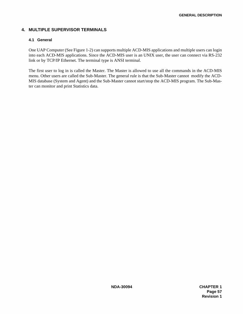
GENERAL DESCRIPTION
4. MULTIPLE SUPERVISOR TERMINALS
4.1 General
One UAP Computer (See Figure 1-2) can supports multiple ACD-MIS applications and multiple users can logininto each ACD-MIS applications. Since the ACD-MIS user is an UNIX user, the user can connect via RS-232link or by TCP/IP Ethernet. The terminal type is ANSI terminal.
The first user to log in is called the Master. The Master is allowed to use all the commands in the ACD-MISmenu. Other users are called the Sub-Master. The general rule is that the Sub-Master cannot modify the ACD-MIS database (System and Agent) and the Sub-Master cannot start/stop the ACD-MIS program. The Sub-Mas-ter can monitor and print Statistics data.
NDA-30094 CHAPTER 1Page 57
Revision 1
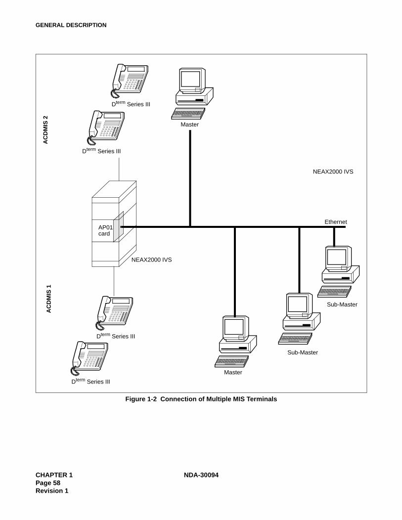
GENERAL DESCRIPTION
Figure 1-2 Connection of Multiple MIS Terminals
AP01card
NEAX2000 IVS
Dterm Series III
Dterm Series III
Master
Ethernet
Sub-Master
Sub-Master
Dterm Series III
Dterm Series III
Master
AC
DM
IS 1
AC
DM
IS 2
NEAX2000 IVS
CHAPTER 1 NDA-30094Page 58Revision 1
INSTALLATION PROCEDURES
CHAPTER 2 INSTALLATION PROCEDURES
1. INTRODUCTION
Installation of the NEAX2000 IVS ACD-MIS system involves a number of actions, which are summarized inthis chapter. In addition, you may need to refer to:
• Chapter 3, Operating Instructions• Specific NEAX2000 IVS manuals• SCO User’s Guide
Before installing the ACD-MIS, the following requirements must be met:
• A personal computer with SCO must be connected to Ethernet.• The NEAX2000 IVS must be equipped with an interface to transmit/receive the control signals between
the PBX and the computer through Ethernet. The interface supports TCP/IP protocol. Refer to "NEAX2000 IVS Open Application Interface (OAI) System Manual" for hardware and software requirements,hardware installation, and system data programming.
• OAI Application Manager (APM) must be installed in the computer. Refer to "APM Installtion Manual"for APM installation.
NDA-30094 CHAPTER 2Page 59
Revision 1
INSTALLATION PROCEDURES
2. SYSTEM HARDWARE SPECIFICATION
2.1 External Display Units
In an ACD environment, an end-user can indicate (to agents) the total number of calls, and the longest periodof time that calls have been in an ACD group queue waiting to be answered. With the ACD-MIS software, ex-ternal display units/wallboards may be interfaced with the personal computer (which provided the MIS capabil-ity).
This wallboard may be centrally located among the agents and can provide the call-waiting information. Thewallboard can provide information on up to seven ACD groups. Up to four wallboards may be interfaced withthe personal computer.
2.2 Required Equipment
In order to provide wallboard capabilities, two items are required in addition to the NEAX2000 IVS system andthe ACD-MIS personal computer:
• A wallboard• A driver board, which is installed into the personal computer. The board provides multiple RS-232 asyn-
cronous communications channels. Reccomended board is DIGI PC/X (from DIGI International Inc, 6400Flying Cloud Dr., Eden Prairie, MN 55344, (800) 344-4273 (612)943-9020). Only one drive board is re-quired for one to four wallboards.
CHAPTER 2 NDA-30094Page 60Revision 1
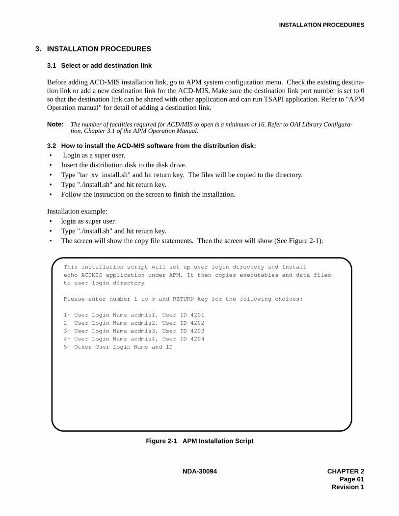
INSTALLATION PROCEDURES
3. INSTALLATION PROCEDURES
3.1 Select or add destination link
Before adding ACD-MIS installation link, go to APM system configuration menu. Check the existing destina-tion link or add a new destination link for the ACD-MIS. Make sure the destination link port number is set to 0so that the destination link can be shared with other application and can run TSAPI application. Refer to "APMOperation manual" for detail of adding a destination link.
Note: The number of facilities required for ACD/MIS to open is a minimum of 16. Refer to OAI Library Configura-tion, Chapter 3.1 of the APM Operation Manual.
3.2 How to install the ACD-MIS software from the distribution disk:• Login as a super user.• Insert the distribution disk to the disk drive.• Type "tar xv install.sh" and hit return key. The files will be copied to the directory.• Type "./install.sh" and hit return key.• Follow the instruction on the screen to finish the installation.
Installation example:• login as super user.• Type "./install.sh" and hit return key.• The screen will show the copy file statements. Then the screen will show (See Figure 2-1):
Figure 2-1 APM Installation Script
This installation script will set up user login directory and Install
echo ACDMIS application under APM. It then copies executables and data files
to user login directory
Please enter number 1 to 5 and RETURN key for the following choices:
1- User Login Name acdmis1, User ID 4201
2- User Login Name acdmis2, User ID 4202
3- User Login Name acdmis3, User ID 4203
4- User Login Name acdmis4, User ID 4204
5- Other User Login Name and ID
NDA-30094 CHAPTER 2Page 61
Revision 1
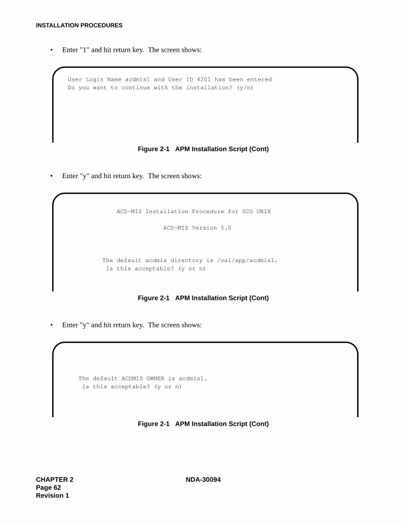
INSTALLATION PROCEDURES
• Enter "1" and hit return key. The screen shows:
Figure 2-1 APM Installation Script (Cont)
• Enter "y" and hit return key. The screen shows:
Figure 2-1 APM Installation Script (Cont)
• Enter "y" and hit return key. The screen shows:
Figure 2-1 APM Installation Script (Cont)
User Login Name acdmis1 and User ID 4201 has been entered
Do you want to continue with the installation? (y/n)
ACD-MIS Installation Procedure for SCO UNIX
ACD-MIS Version 5.0
The default acdmis directory is /oai/app/acdmis1.
Is this acceptable? (y or n)
The default ACDMIS OWNER is acdmis1.
Is this acceptable? (y or n)
CHAPTER 2 NDA-30094Page 62Revision 1
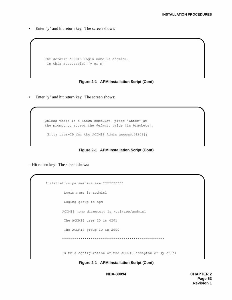
INSTALLATION PROCEDURES
• Enter "y" and hit return key. The screen shows:
Figure 2-1 APM Installation Script (Cont)
• Enter "y" and hit return key. The screen shows:
Figure 2-1 APM Installation Script (Cont)
- Hit return key. The screen shows:
Figure 2-1 APM Installation Script (Cont)
The default ACDMIS login name is acdmis1.
Is this acceptable? (y or n)
Unless there is a known conflict, press "Enter" at
the prompt to accept the default value [in brackets].
Enter user-ID for the ACDMIS Admin account[4201]:
Installation parameters are:**********
Login name is acdmis1
Loging group is apm
ACDMIS home directory is /oai/app/acdmis1
The ACDMIS user ID is 4201
The ACDMIS group ID is 2000
**************************************************
Is this configuration of the ACDMIS acceptable? (y or n)
NDA-30094 CHAPTER 2Page 63
Revision 1
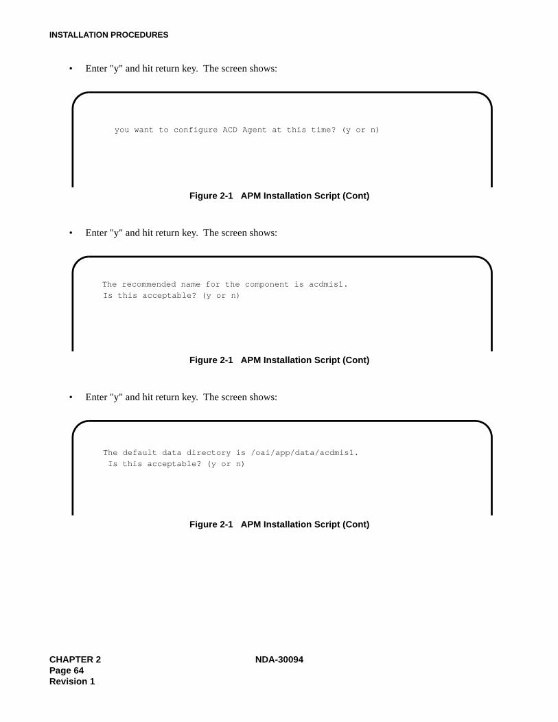
INSTALLATION PROCEDURES
• Enter "y" and hit return key. The screen shows:
Figure 2-1 APM Installation Script (Cont)
• Enter "y" and hit return key. The screen shows:
Figure 2-1 APM Installation Script (Cont)
• Enter "y" and hit return key. The screen shows:
Figure 2-1 APM Installation Script (Cont)
you want to configure ACD Agent at this time? (y or n)
The recommended name for the component is acdmis1.
Is this acceptable? (y or n)
The default data directory is /oai/app/data/acdmis1.
Is this acceptable? (y or n)
CHAPTER 2 NDA-30094Page 64Revision 1
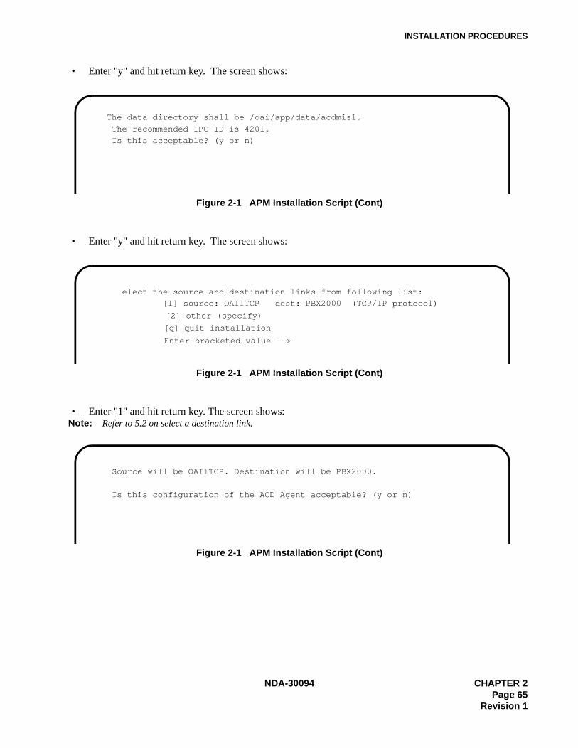
INSTALLATION PROCEDURES
• Enter "y" and hit return key. The screen shows:
Figure 2-1 APM Installation Script (Cont)
• Enter "y" and hit return key. The screen shows:
Figure 2-1 APM Installation Script (Cont)
• Enter "1" and hit return key. The screen shows:Note: Refer to 5.2 on select a destination link.
Figure 2-1 APM Installation Script (Cont)
The data directory shall be /oai/app/data/acdmis1.
The recommended IPC ID is 4201.
Is this acceptable? (y or n)
elect the source and destination links from following list:
[1] source: OAI1TCP dest: PBX2000 (TCP/IP protocol)
[2] other (specify)
[q] quit installation
Enter bracketed value -->
Source will be OAI1TCP. Destination will be PBX2000.
Is this configuration of the ACD Agent acceptable? (y or n)
NDA-30094 CHAPTER 2Page 65
Revision 1
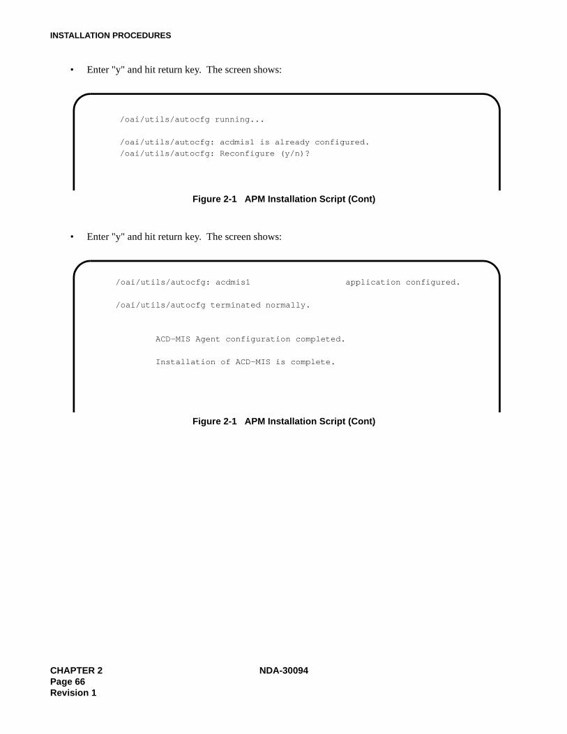
INSTALLATION PROCEDURES
• Enter "y" and hit return key. The screen shows:
Figure 2-1 APM Installation Script (Cont)
• Enter "y" and hit return key. The screen shows:
Figure 2-1 APM Installation Script (Cont)
/oai/utils/autocfg running...
/oai/utils/autocfg: acdmis1 is already configured.
/oai/utils/autocfg: Reconfigure (y/n)?
/oai/utils/autocfg: acdmis1 application configured.
/oai/utils/autocfg terminated normally.
ACD-MIS Agent configuration completed.
Installation of ACD-MIS is complete.
CHAPTER 2 NDA-30094Page 66Revision 1

INSTALLATION PROCEDURES
3.3 ACD-MIS Data Assignment
3.3.1 To activate ACD
Continued on next page
Command Description Data
CM10
Assign the Pilot (phantom) and agents to each LEN. (1) 0000-0511 (LEN)(2) X~XXXX Pilot/Agent station
numberFX~FXXXX Agent station num-
ber
CM12Assign the tenant number to each ACD Pilot and all agents. YY=04
(1) X~XXXX (Station No.)(2) 1 : Tenant Number
CM17
Assign ACD group. For one ACD group, assign station numbers one by one, in the order they will hunt.
Note: Up to 60 stations can be assigned into a singleACD group.
Example: Setting Station Numbers 200, 201, 202 into one ACD group.
Y=0(1) X~XXXX (Station No.)(2) X~XXXX (Another Station
No. to be linked)
Assign the Pilot station and member station.
Note: The Pilot station must be a non-existing LEN(CM10) phantom. Agent stations must be as-signed Prime Line (CM93). Agent station num-bers must be the same number assigned in CM10,CM17, and CM93.
Y=1(1) X~XXXX (ACD Station No.)(2) 1/0 : Pilot Station/Mem-
ber Station
2nd
(1) 200(2) 201(1) 201(2) 202(1) 202(2) 200
1st operation
2nd operation
3rd operation
200
201 202
1st 3rd
NDA-30094 CHAPTER 2Page 67
Revision 1

INSTALLATION PROCEDURES
Continued on next page
Command Description Data
CM17
Assign the ACD Group Number. Y=2(1) X~XXXX (Pilot/Agent Station No.)(2) 00~15 (ACD Group 00~15)
Specify the ACD service for each type of call.Note: Agent station number must be
the same number assigned inCM10, CM17, and CM93.
Y=4 (Internal Call: from station/ATTCON)(1) X~XXXX (Pilot Station No. of the ACD Group)(2) 0/1 : Not to be provided/To be provided
Y=5 (C.O. Incoming Call: DDD: FX/WATS)(1) X~XXXX (Pilot Station No. of the ACD Group)(2) 0/1 : Not to be provided/To be provided
Y=6 (TIE Line Incoming Call)(1) X~XXXX (Pilot Station No. of the ACD Group)(2) 0/1 : Not to be provided/To be provided
Y=7 (DID Call)(1) X~XXXX (Pilot Station No. of the ACD Group)(2) 0/1 : Not to be provided/To be provided
Y=A (Delay Announcement Service)(1) X~XXXX (Pilot Station No. of the ACD Group)(2) 0/1 : To be sent periodically/To be sent once
Y=B (Queue Size Limitation)(1) X~XXXX (Pilot Station No. of the ACD Group)(2) 0/1 : Provided /Not to be provided
CHAPTER 2 NDA-30094Page 68Revision 1

INSTALLATION PROCEDURES
Command Description Data
CM08
Specify the processing for an incoming call when all ACD Stations are busy.
(1) 212(2) 0/1 : Busy Tone Connection /Queuing
Specify the processing for a held call after setting the ACD Busy-Out.
(1) 214 (For the held Call from TIE Line)(2) 0/1 : Reconnected by Switchhook
Flash/ Disconnected
(1) 215 (For the held call from C.O. Line)(2) 0/1 : Reconnected by Switchhook
Flash/ Disconnected
Specify whether the transferred C.O. call from a station or HA-610Z/SN610 ATTCON is placed into queueing mode when all ACD stations are busy.
Note: This data is effective only when CM08-212 is set to 1.
(1) 2270: The call is placed into queueing
mode. Note1 : Recall to the transferring station
(when the call is transferred from station) or attendant Camp-On is set (when the call is transferred from ATTCON.)
Specify the diversion display on a Multiline ter-minal or SN610 ATTCON when originating or terminating an ACD call.
(1) 357(2) 0/1 : Available/Not Available
Transferred C.O. call from a station or HA-610 ATTCON is placed into queueing mode when all ACD stations are busy.
Note: This data must be set to 0 for proper op-eration.
(1) 460(2) 0 : Counts as 1 call.
1 : Counts as 2 calls.
CM93
Specify Prime Line for ACD station number as-signed in CM10 and CM17.
Note: Agent station number must be the samenumber assigned in CM10, CM17, andCM93.
(1) X~XXXX Primary Extension Number (from CM10)
(2) X~XXXX Prime Line (same number as CM10)
(2)
NDA-30094 CHAPTER 2Page 69
Revision 1
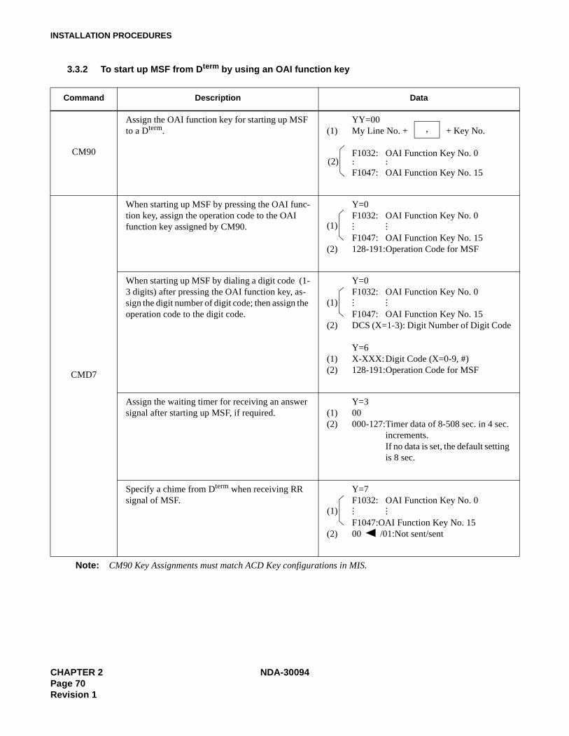
INSTALLATION PROCEDURES
3.3.2 To start up MSF from Dterm by using an OAI function key
Command Description Data
CM90
Assign the OAI function key for starting up MSF to a Dterm.
YY=00(1) My Line No. + + Key No.
F1032: OAI Function Key No. 0 . .. .F1047: OAI Function Key No. 15
CMD7
When starting up MSF by pressing the OAI func-tion key, assign the operation code to the OAI function key assigned by CM90.
Y=0F1032: OAI Function Key No. 0 . .. .. .F1047: OAI Function Key No. 15
(2) 128-191:Operation Code for MSF
When starting up MSF by dialing a digit code (1-3 digits) after pressing the OAI function key, as-sign the digit number of digit code; then assign the operation code to the digit code.
Y=0F1032: OAI Function Key No. 0 . .. .. .F1047: OAI Function Key No. 15
(2) DCS (X=1-3): Digit Number of Digit Code
Y=6(1) X-XXX:Digit Code (X=0-9, #)(2) 128-191:Operation Code for MSF
Assign the waiting timer for receiving an answer signal after starting up MSF, if required.
Y=3(1) 00(2) 000-127:Timer data of 8-508 sec. in 4 sec.
increments.If no data is set, the default setting is 8 sec.
Specify a chime from Dterm when receiving RR signal of MSF.
Y=7F1032: OAI Function Key No. 0. .. .. .F1047:OAI Function Key No. 15
(2) 00 /01:Not sent/sent
Note: CM90 Key Assignments must match ACD Key configurations in MIS.
,
(2)
(1)
(1)
(1)
CHAPTER 2 NDA-30094Page 70Revision 1
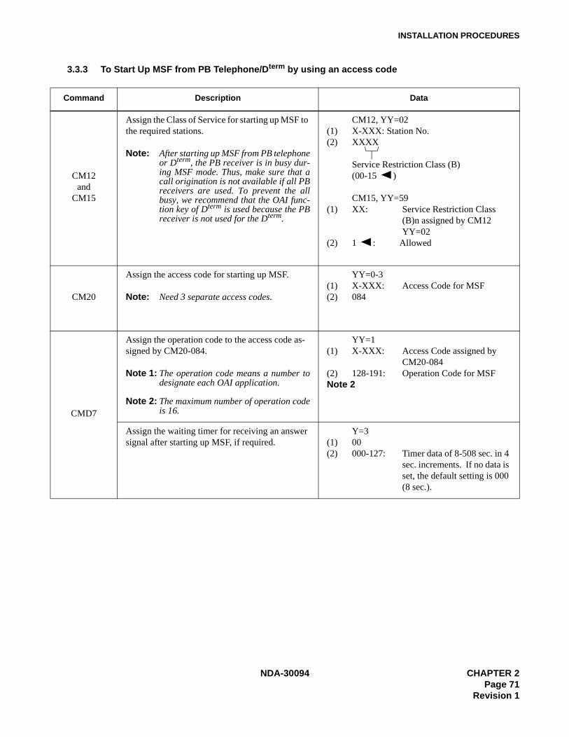
INSTALLATION PROCEDURES
3.3.3 To Start Up MSF from PB Telephone/Dterm by using an access code
Command Description Data
CM12and
CM15
Assign the Class of Service for starting up MSF to the required stations.
Note: After starting up MSF from PB telephoneor Dterm, the PB receiver is in busy dur-ing MSF mode. Thus, make sure that acall origination is not available if all PBreceivers are used. To prevent the allbusy, we recommend that the OAI func-tion key of Dterm is used because the PBreceiver is not used for the Dterm.
CM12, YY=02(1) X-XXX: Station No.(2) XXXX
Service Restriction Class (B)(00-15 )
CM15, YY=59(1) XX: Service Restriction Class
(B)n assigned by CM12 YY=02
(2) 1 : Allowed
CM20
Assign the access code for starting up MSF.
Note: Need 3 separate access codes.
YY=0-3(1) X-XXX: Access Code for MSF(2) 084
CMD7
Assign the operation code to the access code as-signed by CM20-084.
Note 1: The operation code means a number todesignate each OAI application.
Note 2: The maximum number of operation codeis 16.
YY=1(1) X-XXX: Access Code assigned by
CM20-084(2) 128-191: Operation Code for MSFNote 2
Assign the waiting timer for receiving an answer signal after starting up MSF, if required.
Y=3(1) 00(2) 000-127: Timer data of 8-508 sec. in 4
sec. increments. If no data is set, the default setting is 000 (8 sec.).
NDA-30094 CHAPTER 2Page 71
Revision 1
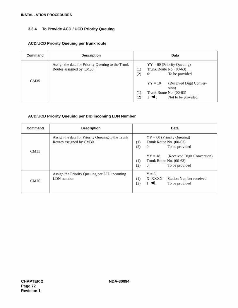
INSTALLATION PROCEDURES
3.3.4 To Provide ACD / UCD Priority Queuing
ACD/UCD Priority Queuing per trunk route
ACD/UCD Priority Queuing per DID incoming LDN Number
Command Description Data
CM35
Assign the data for Priority Queuing to the Trunk Routes assigned by CM30.
YY = 60 (Priority Queuing)(1) Trunk Route No. (00-63)(2) 0: To be provided
YY = 18 (Received Digit Conver-sion)
(1) Trunk Route No. (00-63)(2) 1 : Not to be provided
Command Description Data
CM35
Assign the data for Priority Queuing to the Trunk Routes assigned by CM30.
YY = 60 (Priority Queuing)(1) Trunk Route No. (00-63)(2) 0: To be provided
YY = 18 (Received Digit Conversion)(1) Trunk Route No. (00-63)(2) 0: To be provided
CM76
Assign the Priority Queuing per DID incoming LDN number.
Y = 6(1) X–XXXX: Station Number received(2) 1 : To be provided
CHAPTER 2 NDA-30094Page 72Revision 1
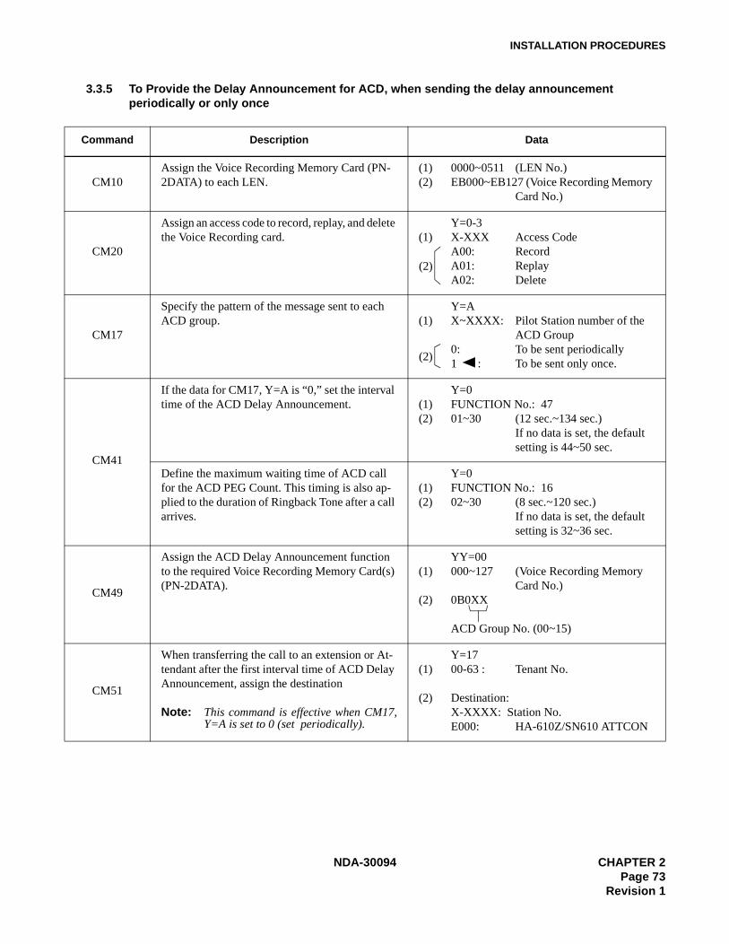
INSTALLATION PROCEDURES
3.3.5 To Provide the Delay Announcement for ACD, when sending the delay announcementperiodically or only once
Command Description Data
CM10Assign the Voice Recording Memory Card (PN-2DATA) to each LEN.
(1) 0000~0511 (LEN No.)(2) EB000~EB127 (Voice Recording Memory
Card No.)
CM20
Assign an access code to record, replay, and delete the Voice Recording card.
Y=0-3(1) X-XXX Access Code
A00: RecordA01: ReplayA02: Delete
CM17
Specify the pattern of the message sent to each ACD group.
Y=A(1) X~XXXX: Pilot Station number of the
ACD Group0: To be sent periodically1 : To be sent only once.
CM41
If the data for CM17, Y=A is “0,” set the interval time of the ACD Delay Announcement.
Y=0(1) FUNCTION No.: 47(2) 01~30 (12 sec.~134 sec.)
If no data is set, the default setting is 44~50 sec.
Define the maximum waiting time of ACD call for the ACD PEG Count. This timing is also ap-plied to the duration of Ringback Tone after a call arrives.
Y=0(1) FUNCTION No.: 16(2) 02~30 (8 sec.~120 sec.)
If no data is set, the default setting is 32~36 sec.
CM49
Assign the ACD Delay Announcement function to the required Voice Recording Memory Card(s) (PN-2DATA).
YY=00(1) 000~127 (Voice Recording Memory
Card No.)(2) 0B0XX
ACD Group No. (00~15)
CM51
When transferring the call to an extension or At-tendant after the first interval time of ACD Delay Announcement, assign the destination
Note: This command is effective when CM17,Y=A is set to 0 (set periodically).
Y=17(1) 00-63 : Tenant No.
(2) Destination:X-XXXX: Station No.E000: HA-610Z/SN610 ATTCON
(2)
(2)
NDA-30094 CHAPTER 2Page 73
Revision 1

INSTALLATION PROCEDURES
3.3.6 To provide the Delay Announcement for ACD, when sending the ACD Second DelayAnnouncement
Command Description Data
CM49
Assign the ACD Second Delay Announcement function to the required Voice Recording Card(s) (PN-2DATA).
YY=00(1) 000-127 (Voice Recording Memory
Card No.)(2) 11XX
ACD Group No. (00-15)
CM08
When a caller encounters all ACD/UCD stations busy
(1) 212(2) 0: Busy Tone Connection
1 : Caller is placed into queuing mode
CM10Assign the Voice Recording Memory Card (PN-2DATA) to each LEN No.
(1) 0000–0511 (LEN No.)(2) EB000–EB127 (Voice Recording Memory
Card No.)
CM17
Assign the pattern of the message to be sent to each ACD group periodically.
Y=A(1) X–XXXX: Pilot Station number of the
ACD Group(2) 0: To be sent periodically
CM41
If the data for CM17, Y=A is “0”, set the interval time of ACD Delay Announcement.
Y=0(1) FUNCTION No.: 47(2) 01-30 (12 sec.-132 sec.)
If no data is set, the default setting is 44-48 sec.
Define the maximum waiting time of ACD Call for the ACD Delay Announcement. This timing is also applied to the duration of Ringback Tone after a call arrives.
Y=0(1) FUNCTION No.: 16(2) 01-30 (12 sec.-132 sec.)
If no data is set, the default setting is 44-48 sec.
CHAPTER 2 NDA-30094Page 74Revision 1
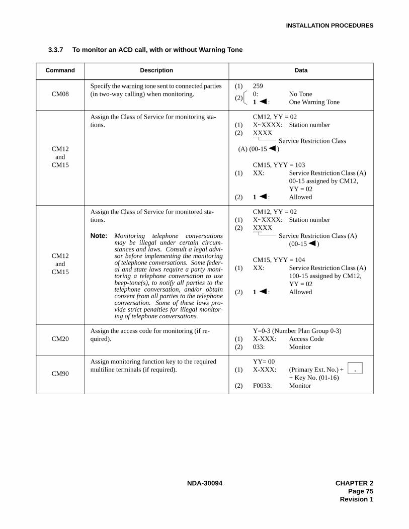
INSTALLATION PROCEDURES
3.3.7 To monitor an ACD call, with or without Warning Tone
Command Description Data
CM08Specify the warning tone sent to connected parties (in two-way calling) when monitoring.
(1) 2590: No Tone1 : One Warning Tone
CM12and
CM15
Assign the Class of Service for monitoring sta-tions.
CM12, YY = 02(1) X~XXXX: Station number (2) XXXX Service Restriction Class (A) (00-15 )
CM15, YYY = 103(1) XX: Service Restriction Class (A)
00-15 assigned by CM12, YY = 02
(2) 1 : Allowed
CM12and
CM15
Assign the Class of Service for monitored sta-tions.
Note: Monitoring telephone conversationsmay be illegal under certain circum-stances and laws. Consult a legal advi-sor before implementing the monitoringof telephone conversations. Some feder-al and state laws require a party moni-toring a telephone conversation to usebeep-tone(s), to notify all parties to thetelephone conversation, and/or obtainconsent from all parties to the telephoneconversation. Some of these laws pro-vide strict penalties for illegal monitor-ing of telephone conversations.
CM12, YY = 02(1) X~XXXX: Station number (2) XXXX Service Restriction Class (A)
(00-15 )
CM15, YYY = 104(1) XX: Service Restriction Class (A)
100-15 assigned by CM12, YY = 02
(2) 1 : Allowed
CM20Assign the access code for monitoring (if re-quired).
Y=0-3 (Number Plan Group 0-3)(1) X-XXX: Access Code(2) 033: Monitor
CM90
Assign monitoring function key to the required multiline terminals (if required).
YY= 00(1) X-XXX: (Primary Ext. No.) +
+ Key No. (01-16)(2) F0033: Monitor
(2)
,
NDA-30094 CHAPTER 2Page 75
Revision 1

INSTALLATION PROCEDURES
3.3.8 To provide the External Indicator for Overflowed ACD Call Waiting
Command Description Data
CM08Assign the incoming call to queuing mode when all ACD stations are busy.
(1) 212(2) 1 : Queuing
CM42
Specify the maximum number of queuing in each ACD group for controlling external equipment interface (PN-DK00).
Note: Depending on the number of queuing station/trunk, the lamp indication pattern on externalequipment is different, as shown in the table be-low::
(1) 15(2) 01-99 (Number of queuing
in each ACD group)If no data is set, the default setting is 01.
CM10
Assign the PN-DK00 Card to the required LEN. (1) LEN (0000~0511)(2) E800~E831 (PN-DK00 card No.)
E800~E807: For PIM0E808~E815: For PIM1E816~E823: For PIM2E824~E831: For PIM3
CM44
Assign the function of ACD Overflow Indication to the PN-DK00.
(1) XXXCircuit No. (0_3)Card No. (00_31) assigned by CM10, E800~E831
(2) 14XXACD Group No. (00_15) assigned by CM17.
CM59
Specify the ACD Overflow Indicator indication pattern. (1) 0001: 30 IPM (1 sec. ON/OFF)02: 60 IPM (0.5 sec. ON/OFF)03: 120 IPM (0.25 sec. ON/OFF)07: Steadily On
N = Number of queuing station/trunk Conditions Lamp indication
2nd Data = 01Lamp on, irrespective of number of queuing station/ trunk. (For the indication pattern, see CM59.)
N < 2nd Data(2nd Data ≠ 01)
Lamp off.
2nd Data ≤ N (2nd Data ≠ 01)
Lamp on. (For the indication pat-tern, see CM59.)
(2)
CHAPTER 2 NDA-30094Page 76Revision 1
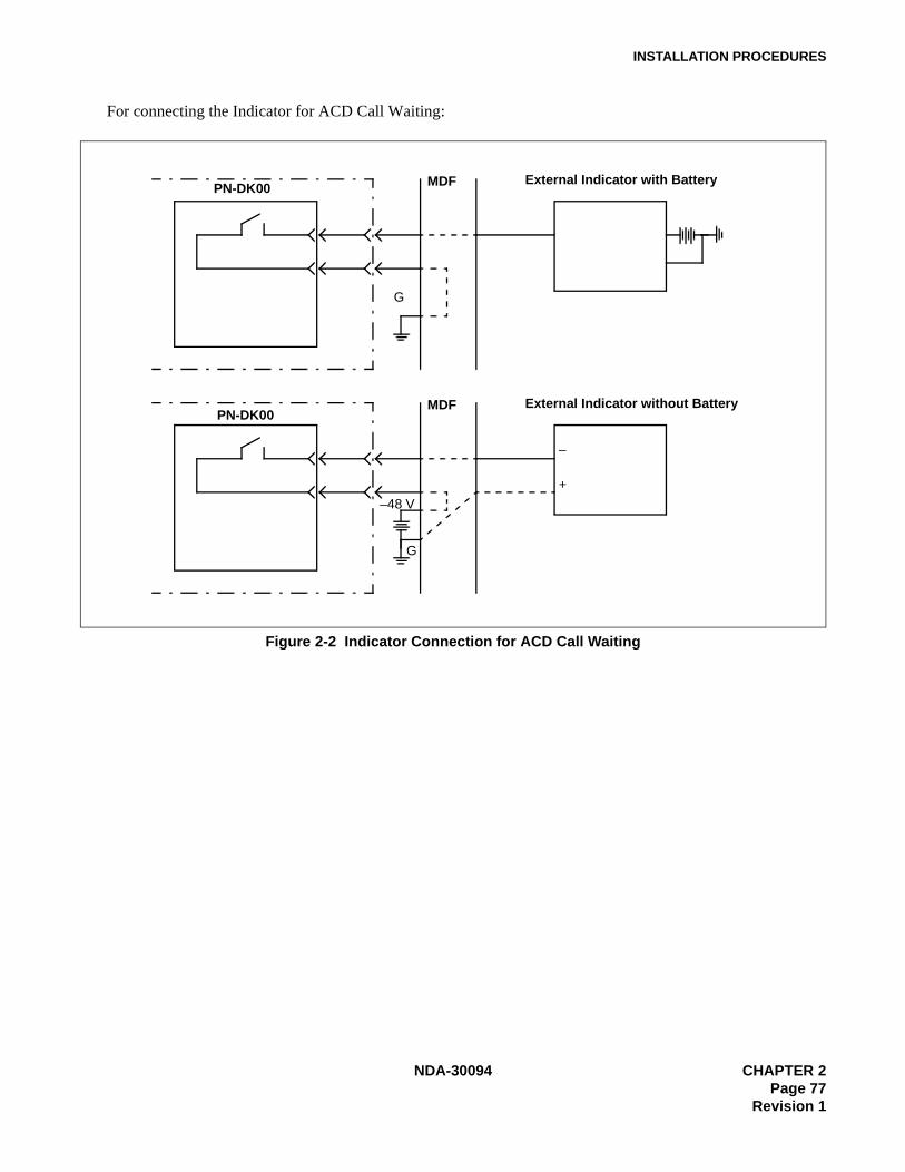
INSTALLATION PROCEDURES
For connecting the Indicator for ACD Call Waiting:
Figure 2-2 Indicator Connection for ACD Call Waiting
–48 V
External Indicator with Battery
G
PN-DK00 MDF
External Indicator without Battery
G
PN-DK00MDF
+
–
NDA-30094 CHAPTER 2Page 77
Revision 1
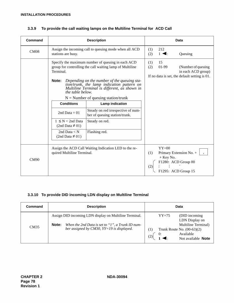
INSTALLATION PROCEDURES
3.3.9 To provide the call waiting lamps on the Multiline Terminal for ACD Call
3.3.10 To provide DID incoming LDN display on Multiline Terminal
Command Description Data
CM08Assign the incoming call to queuing mode when all ACD stations are busy.
(1) 212(2) 1 : Queuing
Specify the maximum number of queuing in each ACD group for controlling the call waiting lamp of Multiline Terminal.
Note: Depending on the number of the queuing sta-tion/trunk, the lamp indication pattern onMultiline Terminal is different, as shown inthe table below.
(1) 15(2) 01-99 (Number of queuing
in each ACD group)If no data is set, the default setting is 01.
CM90
Assign the ACD Call Waiting Indication LED to the re-quired Multiline Terminal.
YY=00(1) Primary Extension No. +
+ Key No.F1280: ACD Group 00. . .. .. .F1295: ACD Group 15
Command Description Data
CM35
Assign DID incoming LDN display on Multiline Terminal.
Note: When the 2nd Data is set to “1”, a Trunk ID num-ber assigned by CM30, YY=19 is displayed.
YY=75 (DID incoming LDN Display on Multiline Terminal)
(1) Trunk Route No. (00-63)(2)0: Available1 : Not available Note
N = Number of queuing station/trunk Conditions Lamp indication
2nd Data = 01Steady on red irrespective of num-ber of queuing station/trunk.
1 ≤ N < 2nd Data(2nd Data ≠ 01)
Steady on red.
2nd Data < N(2nd Data ≠ 01)
Flashing red.
,
(2)
(2)
CHAPTER 2 NDA-30094Page 78Revision 1

INSTALLATION PROCEDURES
3.3.11 To provide DID Number Conversion for an ACD Group
Command Description Data
CM35
Assign the data for DID to the Trunk Routes as-signed by CM30.
YY=12 (Number of digit to be re-ceived)
(1) Trunk Route No. (00-63)0: Available3 : 4 digits
YY=18 (Received digit conversion)(1) Trunk Route No. (00-63)(2) 0: To be provided
YY=78 (Digit conversion of leading 2-4 digits of DID incoming LDN)
(1) Trunk Route No. (00-63)(2) 0: Available
CM76
When CM35 YY=18 is set to “0” (Received Dig-its Conversion is to be provided), assign the data for interpreting the digits received.
Note: When the digit conversion of leading 2-4digits of DID incoming LDN is available(CM35, YY=78, Data=0), leading 2-4digits LDN should be assigned as thefirst data of CM76. (When the DID in-coming LDN is 1 digit, the digit conver-sion for only one digit is not available.
Y=0 (Day Mode)Y=1 (Night Mode)
(1) X–XXXX: Station Number received.X–XXXX: Station/Data Station Number
to be terminated.DXX: Change Terminating System
to:D01D13: TASD04: DITD14: HA-610Z/ SN610 AT-
TCOND16: DISAD09: Automated Attendant
(PN-2DATA)
(2)
(2)
NDA-30094 CHAPTER 2Page 79
Revision 1
INSTALLATION PROCEDURES
3.4 How to run the ACD-MIS
Note: The remaining steps refer to entering specific customer data and performing an initial check of the system’soperation.
Step 1. Enter the unrestricted default password mis (lower case letters). The Main Menu will be displayed.
Note: Steps 7, 8, and 9 are required for minimum system configuration.
Step 2. Specify the required ACD Groups(s). Do not enter more than 12 characters per Group Name.
Step 3. Enter the required Station Details. Be sure that the correct assignment of extension (e.g., analog ordigital) has been made.
Step 4. Enter the required agent detail.
Step 5. Enter the required ACD key detail. Be sure that the PABX assignment matches the ACD-MIS as-signment.
Step 6. Configure the required Report Time Values.
Step 7. Configure any requirement for Storage Intervals.
Step 8. Format the correct date format.
Step 9. Perform the required Report Configurations.
Step 10. Perform the required Report Group Configurations.
Step 11. Set the requirements for Report Scheduler.
Step 12. Set the required Group Statistics Threshold.
Step 13. Set the required Agent Statistics Threshold.
Step 14. Program the required passwords and their individual access arrangements. Include the new namefor the default password “mis” (where specified), and the altered access status of the default pass-word ENTER key.
Step 15. Allow a suitable time for collection of preliminary data, then verify the recording of statistics.
3.5 Hardware Required
• To provide the delay announcement for ACD: PN-2DATA card
• To provide the Indicator for Overflowed ACD Call Waiting: PN-DK00 Card X 1
• External Indicator (visual or audible type) provided by the customer.
CHAPTER 2 NDA-30094Page 80Revision 1

INSTALLATION PROCEDURES
4. TROUBLESHOOTING
4.1 General
This section explains the troubleshooting information to be used after installing the ACD-MIS system.
4.2 Troubleshooting ProceduresNote: See NEAX2000 IVS System manual for troubleshooting on TCP/IP link.
Table 2-1 Troubleshooting Procedures
Trouble Cause Action
(1) Entering a password has no effect.
Improper password. Reenter correct password.
(2) In Statistics Monitor Mode, an extension does not appear for a group.
The PC does not expect messages for these extensions.
Make sure that all assignments in the station configuration are equipped for the exten-sions to be reported.
(3) Wall Boards cause improper operation or lock up.
Stargate Driver version 2.0 Obtain version 1.0 or 4.0 drivers.
NDA-30094 CHAPTER 2Page 81
Revision 1

INSTALLATION PROCEDURES
5. EXTERNAL DISPLAY UNIT (EDU) SET-UP
The following instructions refer to the EDU/PC hardware (Figures 2-3 through 2-4) and software aspects only.Programming of the customer specifications is done in conjunction with the MIS Set-Up procedures.
5.1 RS-232C Board (DIGI PC/X) Installation• Install the RS-232C driver board according to the DIGI PC/X board installation manual.
CHAPTER 2 NDA-30094Page 82Revision 1
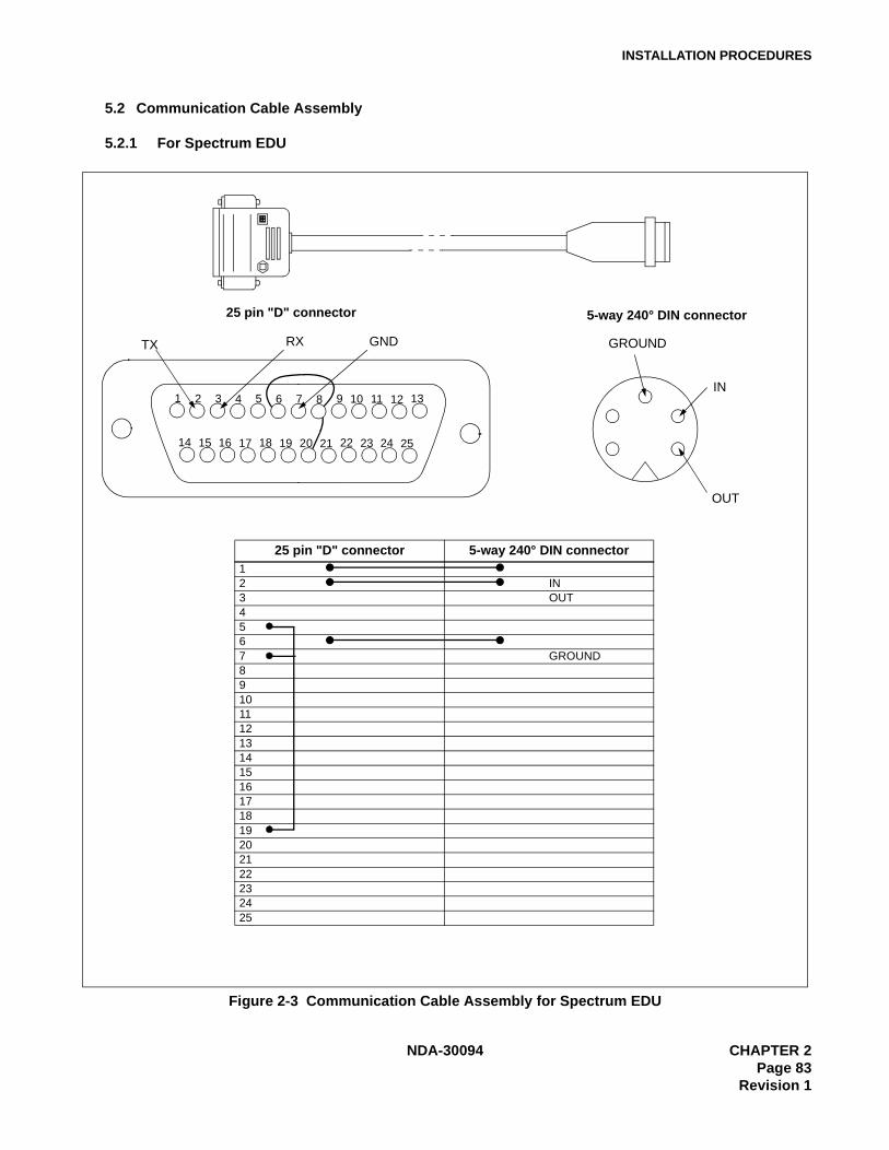
INSTALLATION PROCEDURES
5.2 Communication Cable Assembly
5.2.1 For Spectrum EDU
Figure 2-3 Communication Cable Assembly for Spectrum EDU
1 2 3 4 5 6 7 8 9 10 11 12 13
14 15 16 17 18 19 20 21 22 23 24 25
TX RX GND
25 pin "D" connector 5-way 240° DIN connector12 IN3 OUT4567 GROUND8910111213141516171819202122232425
25 pin "D" connector 5-way 240° DIN connector
IN
OUT
GROUND
NDA-30094 CHAPTER 2Page 83
Revision 1
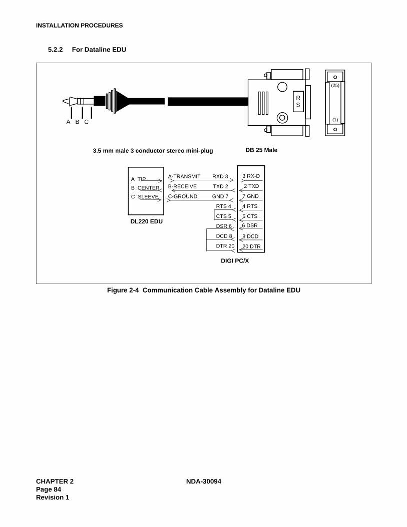
INSTALLATION PROCEDURES
5.2.2 For Dataline EDU
Figure 2-4 Communication Cable Assembly for Dataline EDU
R
A B C
(25)
(1)
A TIP
3.5 mm male 3 conductor stereo mini-plug
DL220 EDU
DB 25 Male
3 RX-DA-TRANSMIT RXD 3
RTS 4
DIGI PC/X
2 TXD
7 GND
4 RTS
5 CTS
6 DSR
8 DCD
20 DTR
CTS 5
DSR 6
DCD 8
DTR 20
B CENTER
C SLEEVE
B-RECEIVE TXD 2
C-GROUND GND 7
S
CHAPTER 2 NDA-30094Page 84Revision 1

INSTALLATION PROCEDURES
5.3 Display Mounting
Refer to the DIGI PC/X Manual (PC/Xe, AccelePort Xe, Intelligent Asynchronous Serial CommunicationsBoards) for the installation of the DIGI PC/Xe board and the board switch settings.
Refer to DIGI MenuPort Interface (MPI) SCO UNIX Manual for installation of the DIGI driver software.
NDA-30094 CHAPTER 2Page 85
Revision 1
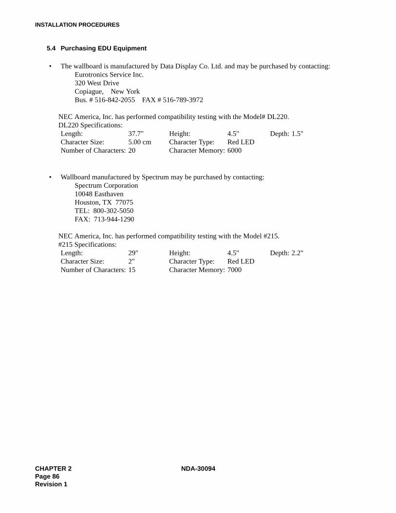
INSTALLATION PROCEDURES
5.4 Purchasing EDU Equipment
• The wallboard is manufactured by Data Display Co. Ltd. and may be purchased by contacting:Eurotronics Service Inc.320 West DriveCopiague, New YorkBus. # 516-842-2055 FAX # 516-789-3972
NEC America, Inc. has performed compatibility testing with the Model# DL220.DL220 Specifications:Length: 37.7" Height: 4.5" Depth: 1.5"Character Size: 5.00 cm Character Type: Red LEDNumber of Characters: 20 Character Memory: 6000
• Wallboard manufactured by Spectrum may be purchased by contacting:Spectrum Corporation10048 EasthavenHouston, TX 77075TEL: 800-302-5050FAX: 713-944-1290
NEC America, Inc. has performed compatibility testing with the Model #215.#215 Specifications:Length: 29" Height: 4.5" Depth: 2.2"Character Size: 2" Character Type: Red LEDNumber of Characters: 15 Character Memory: 7000
CHAPTER 2 NDA-30094Page 86Revision 1
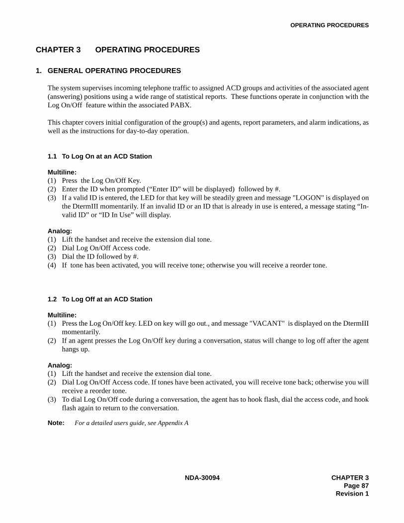
OPERATING PROCEDURES
CHAPTER 3 OPERATING PROCEDURES
1. GENERAL OPERATING PROCEDURES
The system supervises incoming telephone traffic to assigned ACD groups and activities of the associated agent(answering) positions using a wide range of statistical reports. These functions operate in conjunction with theLog On/Off feature within the associated PABX.
This chapter covers initial configuration of the group(s) and agents, report parameters, and alarm indications, aswell as the instructions for day-to-day operation.
1.1 To Log On at an ACD Station
Multiline:(1) Press the Log On/Off Key.(2) Enter the ID when prompted (“Enter ID” will be displayed) followed by #.(3) If a valid ID is entered, the LED for that key will be steadily green and message "LOGON" is displayed on
the DtermIII momentarily. If an invalid ID or an ID that is already in use is entered, a message stating “In-valid ID” or “ID In Use” will display.
Analog:(1) Lift the handset and receive the extension dial tone.(2) Dial Log On/Off Access code.(3) Dial the ID followed by #.(4) If tone has been activated, you will receive tone; otherwise you will receive a reorder tone.
1.2 To Log Off at an ACD Station
Multiline:(1) Press the Log On/Off key. LED on key will go out., and message "VACANT" is displayed on the DtermIII
momentarily.(2) If an agent presses the Log On/Off key during a conversation, status will change to log off after the agent
hangs up.
Analog: (1) Lift the handset and receive the extension dial tone.(2) Dial Log On/Off Access code. If tones have been activated, you will receive tone back; otherwise you will
receive a reorder tone.(3) To dial Log On/Off code during a conversation, the agent has to hook flash, dial the access code, and hook
flash again to return to the conversation.
Note: For a detailed users guide, see Appendix A
NDA-30094 CHAPTER 3Page 87
Revision 1

OPERATING PROCEDURES
1.3 To Set Break
Multiline:(1) Agent presses the Break key; the LED flashes slowly and message "BREAK" is displayed on the DtermIII
momentarily.(2) If the agent presses the Break key during a conversation, the status will change to Break after hangup.
Analog:(1) Lift the handset and receive dial tone.(2) Dial Break code.(3) To dial the Break code during conversation, the agent has to hook flash, dial the code, and hook flash again
to return to the conversation.
1.4 To Cancel Break
Multiline: • The agent presses the Break key; the LED goes out.
Analog:• The agent dials the Break code.
1.5 To Set Work• Use the same operating procedure as Break.
1.6 To Cancel Work• Use the same operating procedure as Break.
1.7 To Monitor Conversation / To Cancel Monitoring
(1) Lift the handset or depress SPKR, and receive the extension dial tone.(2) Dial the monitor feature access code, or press the MONITOR key.(3) Dial the extension number to be monitored.(4) Monitor the conversation via handset or speaker.(5) When the monitored station goes on hook and receives a second call, pressing the MONITOR key re-es-
tablishes the Monitor Feature.
Note: Monitoring telephone conversations may be illegal under certain circumstances and laws. Consult a legaladvisor before implementing the monitoring of telephone conversations. Some federal and state laws requirea party monitoring a telephone conversation to use beep tone(s), to notify all parties to the telephone conver-sation, and/or obtain consent from all parties to the telephone conversation. Some of these laws provide strictpenalties for illegal monitoring of telephone conversations.
CHAPTER 3 NDA-30094Page 88Revision 1
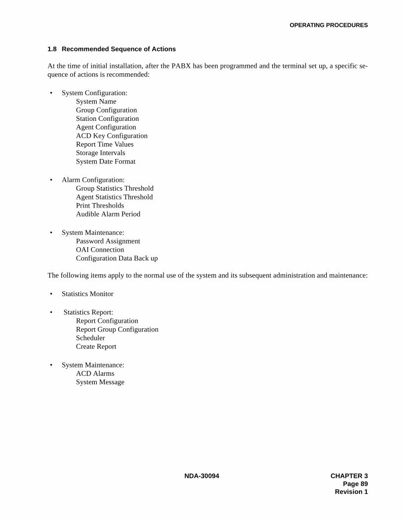
OPERATING PROCEDURES
1.8 Recommended Sequence of Actions
At the time of initial installation, after the PABX has been programmed and the terminal set up, a specific se-quence of actions is recommended:
• System Configuration:System NameGroup ConfigurationStation ConfigurationAgent ConfigurationACD Key ConfigurationReport Time ValuesStorage IntervalsSystem Date Format
• Alarm Configuration:Group Statistics ThresholdAgent Statistics ThresholdPrint ThresholdsAudible Alarm Period
• System Maintenance:Password AssignmentOAI ConnectionConfiguration Data Back up
The following items apply to the normal use of the system and its subsequent administration and maintenance:
• Statistics Monitor
• Statistics Report:Report ConfigurationReport Group ConfigurationSchedulerCreate Report
• System Maintenance:ACD AlarmsSystem Message
NDA-30094 CHAPTER 3Page 89
Revision 1
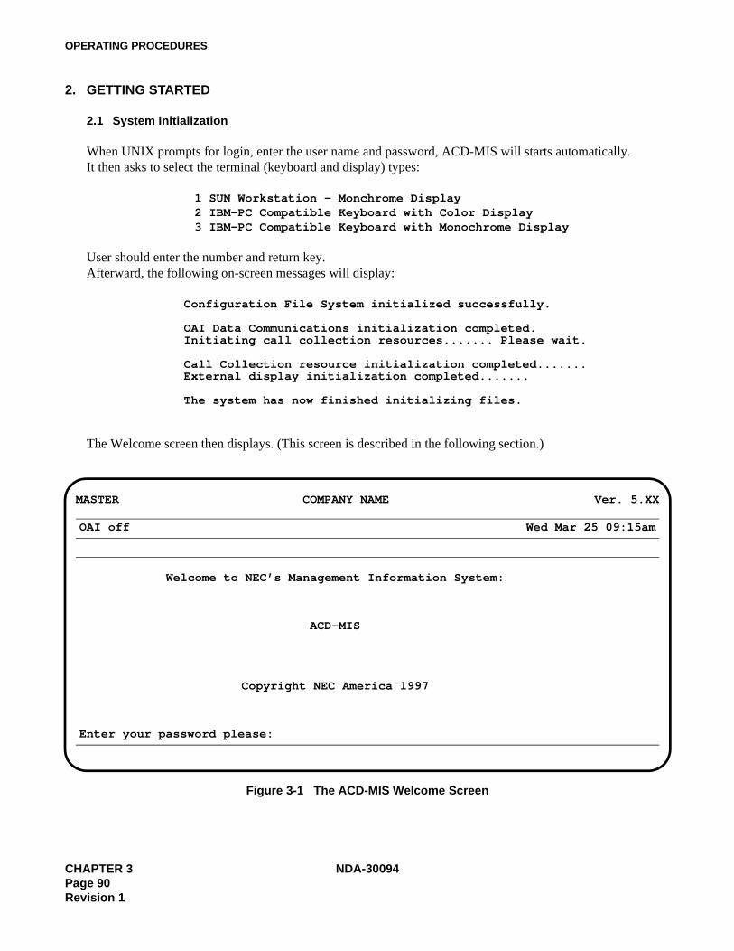
OPERATING PROCEDURES
2. GETTING STARTED
2.1 System Initialization
When UNIX prompts for login, enter the user name and password, ACD-MIS will starts automatically.It then asks to select the terminal (keyboard and display) types:
1 SUN Workstation - Monchrome Display2 IBM-PC Compatible Keyboard with Color Display3 IBM-PC Compatible Keyboard with Monochrome Display
User should enter the number and return key.Afterward, the following on-screen messages will display:
Configuration File System initialized successfully.
OAI Data Communications initialization completed.Initiating call collection resources....... Please wait.
Call Collection resource initialization completed.......External display initialization completed.......
The system has now finished initializing files.
The Welcome screen then displays. (This screen is described in the following section.)
Figure 3-1 The ACD-MIS Welcome Screen
MASTER COMPANY NAME Ver. 5.XX
OAI off Wed Mar 25 09:15am
Welcome to NEC’s Management Information System:
ACD-MIS
Copyright NEC America 1997
Enter your password please:
CHAPTER 3 NDA-30094Page 90Revision 1
OPERATING PROCEDURES
2.2 The Welcome Screen
The very top line (blue banner) is used to display the name of your company or organization. This can be pro-grammed by the customer or preset during the production process.
The type of terminal (Master or Submaster) is indicated in the upper left corner (blue banner).
The version number is indicated in the right-hand corner.
The next line (amber banner) is used to indicate the OAI port status on the left-hand side (i.e., OAI on/off). Thisfunction is controlled from a user option (which will be explained later).
On the right side, the current date and time display. These have been set during installation and should not re-quire adjustment except for time changes.
The bottom line (red banner) is normally blank. The left-hand part displays system information (error codes) orwarning messages. Error codes are only of interest to the service technician; but warning messages may displayif you have overlooked something concerning the printer or floppy disk drive.
A warning message will overwrite any currently displayed error code and will be accompanied by a standardrequest for your response (in the right-hand part). A typical example is:
Printer not on line: Retry (Y/N)?
Other available messages are listed below:Messages related to the printer:
Printer out of paperPrinter cable disconnectedPrinter unknown error
Messages related to the disk drive:Floppy Disk protectedFloppy Drive not readyFloppy Disk faultyFloppy Disk unformattedFloppy Drive problem: . . . .
Note: Printer-related messages are displayed for a maximum of 5 minutes.
NDA-30094 CHAPTER 3Page 91
Revision 1

OPERATING PROCEDURES
2.3 Passwords
Access to each area of ACD-MIS operation can be controlled by passwords, which are preset at installation orspecified by the user to suit individual requirements. The following basic facts apply:
• Accessible menu items appear in white; those that are restricted are amber color.• You can use the preset password (mis in lowercase letters) to access to all items without restriction. If you
wish, you can assign a different name later.• A menu item indicated as restricted can be accessed if you enter the appropriate password. (When the item
is selected, the message Enter Password displays.)
Note: Programming of passwords is described in “Passwords” , Section 6.1.
2.4 Moving Through the Menus
After an appropriate password has been entered, the Main Menu of six items (described in Chapter 1) is dis-played. The cursor will be positioned at Item 1 - Statistics Monitor.
You can identify individual items on any menu by scrolling the cursor. A brief summary of the functions ofeach will be displayed at the bottom of the screen.
Any allowed feature can be directly selected by pressing the appropriate digit key. Otherwise, press the Enterkey once the cursor is located at a required item.
2.5 Key FunctionsOften-used keys are summarized in Table 3-1:
CHAPTER 3 NDA-30094Page 92Revision 1

OPERATING PROCEDURES
Table 3-1 Specific Key Functions
Key(s) Function(s)
Arrow keys
TAB
SHIFT + TAB
SPACEBAR
ENTER
PAGE DOWN
PAGE UP
ESC
F3
F4
F1
General control of cursor position
Move the cursor horizontally across separate fields, from left to right
Move the cursor horizontally across separate fields, from right to left
Toggle various parameter options (listed at bottom of screen) during data specification
- Enter specified data into system memory- Alternate between System + Group and Group + Agent screen displays in the Statistics
Monitor mode
- Complete data entry for particular set-up screen and return to menu- Display next page of registrations within the Group or Agent Detail screens (see also F3)
Display previous page - as above
Abort the function currently being performed and return to associated submenu (except System Alarms and Alarm Configuration Print features)
Scroll forward through the various System/Group Statistics or Group/Agent Statistics screens within the Statistics monitor mode
Scroll in reverse as above
Access help screen as indicated by particular on-screen messages.
NDA-30094 CHAPTER 3Page 93
Revision 1
OPERATING PROCEDURES
3. STATISTICS MONITORING
The Statistics Monitor mode involves a total of seven separate screen displays, each of which is divided into twoportions. The first four screens present combined System and Group Statistics. The remaining three screenspresent Group and Agent Statistics. In either case, the last screen also includes specific system details (e.g.,ACD group indial numbers, agent names, etc.).
By simple key operations it is possible to scroll forward and in reverse through the various System/Group andGroup/Agent screens. From any System and Group Statistics display you can select a particular ACD groupand change to its first associated Group and Agent Statistics screen.
Step 1. From the Main Menu, press 1.
The first Statistics Monitor screen displays. The information within the upper window (System Sta-tistics) refers to the total system. The lower window (Group Statistics) registers the assigned ACDgroups together with their individual values for the same statistics. Note the cursor position at thefirst group. From here you can transfer to several alternative displays.
Step 2. Press F3. The right-hand side only of the screen will change to display a different set of commonSystem and Group Statistics.
Step 3. Press F3 again. The right-hand side will now display the third and last set of common System andGroup Statistics.
Step 4. Press F3 again. The right-hand side will now display only the indial numbers for the respectiveACD groups.
Step 5. If F3 is pressed again, the display reverts to the original screen.
Alternatively, by repetitive pressing of F4 you can scroll in reverse through all previous screens.
Step 6. While viewing any of these screens, move the cursor bar to a required ACD group and pressENTER. The display will change to that first set of common Group and Agent Statistics for thegroup.
Step 7. Press F3 again. Only the lower right-hand side will change to display a different set of Agent Sta-tistics.
Step 8. Press F3 again. The lower window right hand side will now display details of the individual agents(i.e., group and tenant numbers, etc.).
Step 9. If F3 is pressed again, the display will revert to the original screen. Alternatively, by repetitivepressing of F4 you can scroll in reverse through the previous two screens.
Step 10. Press ENTER to return to the original System/Group screen.
Step 11. If required, move the cursor to another group and repeat the above from Step 6.
Step 12. When appropriate, press ESC to return to the Main Menu.
Note: You can scroll through the screens only when there are agents logged on.
CHAPTER 3 NDA-30094Page 94Revision 1
OPERATING PROCEDURES
4. STATISTICS REPORTING
This function enables printing or display of statistical records as a range of seven ACD-group-related reportsand one agent-related report.
In general, ACD-MIS stores information for two separate maximum periods:• For reports with detailed hourly (or more regular) summaries of call statistics, the limit is 45 days. There-
after, records are deleted daily at midnight, with a new file created for the next day.• For all daily summary reports, information is stored for up to two years. Thereafter, the records are deleted
on an annual basis.
The information presented for the ACD group-related reports can be broken down by one of several options ac-cording to period, date, day of the week, etc. However, for the agent-related report, only totals are produced.(See Table 3-2 below.)
From the Main Menu, press 2. The REPORT submenu displays.
The first three items in the REPORT submenu are interrelated and are associated only with the scheduled print-ing of summary reports. In the initial setting up of any requirements, they must be applied in the order listed.They can be accessed freely for modification to or deletion of specifications.
Item 1 - Report Configuration - Structure individual reportsItem 2 - Report Group Configuration - Specify sets of related reportsItem 3 - Scheduler - Specify printing arrangementsItem 4 - Create Report - (for immediate display or printing of reports) is
independent of the others and can be selected at any time.
Table 3-2 Breakdown of Report Statistics
Breakdown type
By Period Detailed Summary Data Up to 45 Working Days from Today
By Hour
By Day of WeekDaily Summary Data Up to the Start of Last YearBy Date
By Month
By Total
NDA-30094 CHAPTER 3Page 95
Revision 1
OPERATING PROCEDURES
4.1 Report Configuration
Step 1. From the Statistics Report submenu, press 1. The Report Configuration screen displays.
Step 2. Type in the preferred Report Name and press ENTER. The cursor will move to the Report Typeparameter. All parameters will display their default values. If the entered Report Name already ex-ists, current assignments will be displayed instead and the cursor will move to the Action parameter.
Action allows existing Report Configurations to be controlled by two options:
Modify: change any current parameter selection(s)Delete: erase the entire report configuration from system memory
To modify a Report Name, move the cursor back to the first line and using the Arrow, DELETE,BACK SPACE, and INSERT keys, delete the necessary characters, re-type the new details andpress ENTER again.
Report Name should be a meaningful title (using a maximum of 20 alphanumeric characters).
If the requirement is to delete the particular Report Configuration, select the Delete option for theAction parameter and go to Step 7.
Step 3. For both initial assignment and later modification, select the required Report Type from the listingat the bottom of the screen either by toggling (with SPACE BAR) or pressing the indicated digit(1-8). Then press ENTER.
Report Type indicates the statistical reports relating to ACD group and agent performance. Eachreport is described in Chapter 1, Section 3.4.5 - Report Data.
Step 4. Enter your requirements for Class.
Class can be defined as:Full Statistics for all existing ACD groups are included in one report.All The same statistics are presented in separate reports for each ACD group.Selected Specified when reporting on a single ACD group
Step 5. Enter your requirement for Date Type. Date Type is one of the ten reporting periods listed on-screen.
Step 6. Enter your requirement for the parameter Breakdown.
Breakdown tallies statistics per line, for the specified Date Type reporting period (by period, hourly,daily, monthly, weekly, or total).
Step 7. Press PAGE DOWN. Confirm your entries then press E, D, R, or C according to:
Execute = enter specifications or changes and return to Report Name for the next entryDefault = during modification, return to original selections and repeat all entriesRedo = return to original selections and repeat selected entries onlyCancel = revert to system default options without effecting any entries or changes.
Step 8. Press ESC at any time to return to the submenu.
CHAPTER 3 NDA-30094Page 96Revision 1

OPERATING PROCEDURES
4.2 Report Group Configuration
Step 1. From the Statistics Report submenu, press 2.
The Report Group Configuration screen will display.
Step 2. Type in the selected Report Group Name then press ENTER. The cursor will move to the first lineof the Report parameter. If an existing Report Group Name is specified, the range of included re-ports and assigned parameters will be displayed. For a new entry, the no report default value willinstead be displayed.
To modify a Report Group Name (up to 20 alphanumeric characters), move the cursor back to thefirst line and using the Arrow, DELETE, BACK SPACE, and INSERT keys, delete the necessarycharacters, re-type the new details and press ENTER again.
Step 3. For either initial assignment or later modification, select the required Report from the listing at thebottom of the screen either by toggling with SPACE BAR or pressing the indicated letter (a, b, c,etc.). Then press ENTER.
The listed options for Report (Name) are those assigned as in Report Configuration. To delete aparticular report from a Report Group, position the cursor at the specific Report (Name) and by themethod described above, change the selection to no report. To totally erase a Report Group, do thisfor each Report (Name) entry.
Note: The requirement to enter data in Steps 4 - 8 is dependent on your selection for certain parame-ters in Report Configuration. In several cases they will not be required. The applicable condi-tions are specified in the following text.
Step 4. Press TAB to move the cursor to Group. The pilot extension numbers of all assigned ACD groupswill now be displayed.
Step 5. For both initial assignment and modification of existing specifications, select the required Group’spilot extension by toggling the displayed options with the SPACE BAR or by pressing the indicatedletter a, b, c, etc.
Entry of Group is necessary only where the Selected Class has been specified (in Report Configu-ration).
The Agent parameter has no application in the current version ACD-MIS and is omitted.
Step 6. Press TAB twice to move the cursor direct to Start Date. Type in the (mm/dd/yy) details wherenecessary. Start Date is required only for Date entries:
For date - to indicate a complete reporting periodDate range - to indicate commencement of a reporting period.
Step 7. Press TAB to move to End Date and type in the necessary (mm/dd/yy) details. End Date is requiredonly for Date entry: date range - to indicate completion of the relevant reporting period.
Step 8. If required, press TAB to move the cursor now to Report Name on the next line and repeat the pro-cedures from Step 3 for any further entry.
Step 9. Press PAGE DOWN to confirm your entries. The screen will return to the submenu.
NDA-30094 CHAPTER 3Page 97
Revision 1
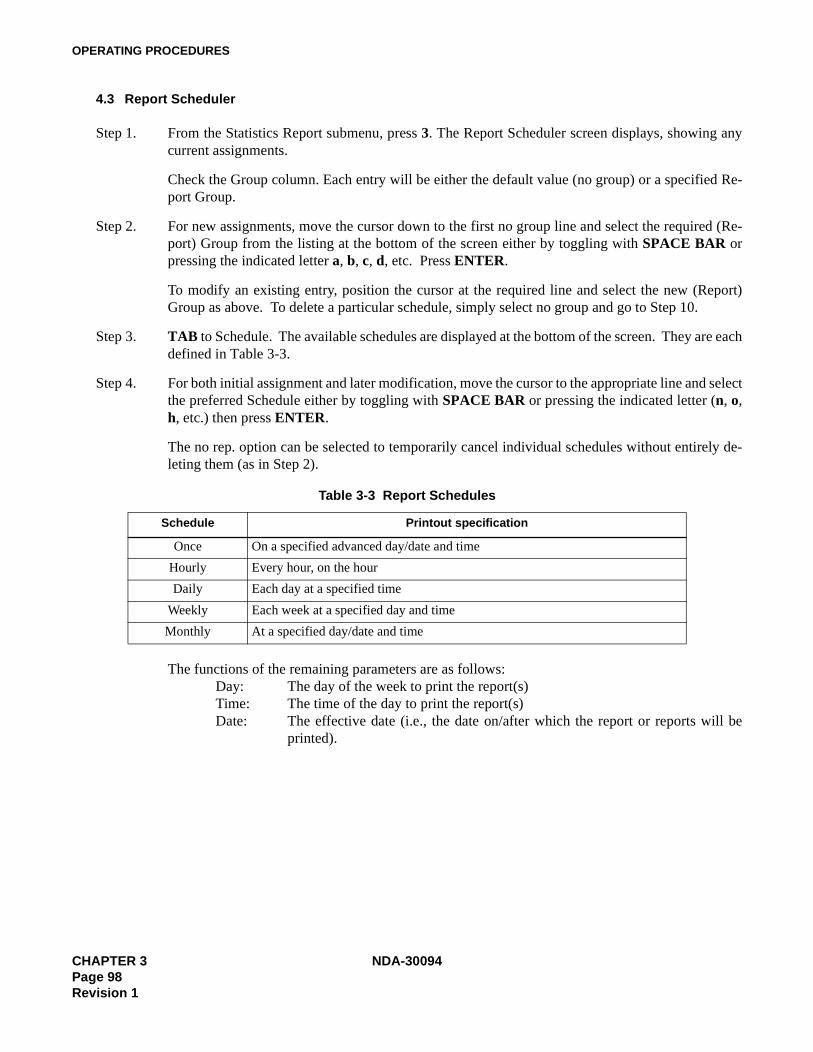
OPERATING PROCEDURES
4.3 Report Scheduler
Step 1. From the Statistics Report submenu, press 3. The Report Scheduler screen displays, showing anycurrent assignments.
Check the Group column. Each entry will be either the default value (no group) or a specified Re-port Group.
Step 2. For new assignments, move the cursor down to the first no group line and select the required (Re-port) Group from the listing at the bottom of the screen either by toggling with SPACE BAR orpressing the indicated letter a, b, c, d, etc. Press ENTER.
To modify an existing entry, position the cursor at the required line and select the new (Report)Group as above. To delete a particular schedule, simply select no group and go to Step 10.
Step 3. TAB to Schedule. The available schedules are displayed at the bottom of the screen. They are eachdefined in Table 3-3.
Step 4. For both initial assignment and later modification, move the cursor to the appropriate line and selectthe preferred Schedule either by toggling with SPACE BAR or pressing the indicated letter (n, o,h, etc.) then press ENTER.
The no rep. option can be selected to temporarily cancel individual schedules without entirely de-leting them (as in Step 2).
The functions of the remaining parameters are as follows:Day: The day of the week to print the report(s)Time: The time of the day to print the report(s)Date: The effective date (i.e., the date on/after which the report or reports will be
printed).
Table 3-3 Report Schedules
Schedule Printout specification
Once On a specified advanced day/date and time
Hourly Every hour, on the hour
Daily Each day at a specified time
Weekly Each week at a specified day and time
Monthly At a specified day/date and time
CHAPTER 3 NDA-30094Page 98Revision 1
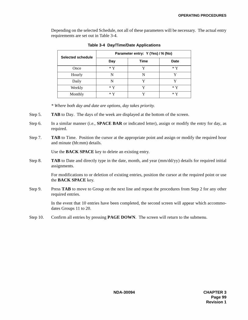
OPERATING PROCEDURES
Depending on the selected Schedule, not all of these parameters will be necessary. The actual entryrequirements are set out in Table 3-4.
* Where both day and date are options, day takes priority.
Step 5. TAB to Day. The days of the week are displayed at the bottom of the screen.
Step 6. In a similar manner (i.e., SPACE BAR or indicated letter), assign or modify the entry for day, asrequired.
Step 7. TAB to Time. Position the cursor at the appropriate point and assign or modify the required hourand minute (hh:mm) details.
Use the BACK SPACE key to delete an existing entry.
Step 8. TAB to Date and directly type in the date, month, and year (mm/dd/yy) details for required initialassignments.
For modifications to or deletion of existing entries, position the cursor at the required point or usethe BACK SPACE key.
Step 9. Press TAB to move to Group on the next line and repeat the procedures from Step 2 for any otherrequired entries.
In the event that 10 entries have been completed, the second screen will appear which accommo-dates Groups 11 to 20.
Step 10. Confirm all entries by pressing PAGE DOWN. The screen will return to the submenu.
Table 3-4 Day/Time/Date Applications
Selected scheduleParameter entry: Y (Yes) / N (No)
Day Time Date
Once * Y Y * Y
Hourly N N Y
Daily N Y Y
Weekly * Y Y * Y
Monthly * Y Y * Y
NDA-30094 CHAPTER 3Page 99
Revision 1
OPERATING PROCEDURES
4.4 Create Report
Step 1. From the Statistics Report submenu, press 4. The Report Select screen will be displayed. All pa-rameters will display their default values.
Step 2. Select the required Report Type from the listing at the bottom of the screen by toggling with theSPACE BAR or pressing the indicated digit 1 - 8, then press ENTER. The cursor moves to Des-tination.
Report Type indicates the statistical reports relating to ACD group and agent performance. Each isdescribed in Section 5.5 - Report Data.
Step 3. The system defaults to the Screen option. To select printer or file, press SPACE BAR or the letterp or f.
Press ENTER. The cursor moves to Class.
Step 4. Select the required Class by toggling with the SPACE BAR or pressing f, a, or s.
Then press ENTER.
Step 5.
• If you entered either Full or All Class, the cursor will move to Date Type. Go to Step 6.
• If instead you entered Selected Class, the cursor will move to Selected. The pilot extensions of allassigned ACD groups will be displayed at the bottom of the screen.
Select the required Group by toggling the SPACE BAR or pressing a, b, etc.Press ENTER. The cursor will now move to Date Type.
Step 6. Enter your selection for Date Type.
Step 7.
• For any selection of Date Type except for date and date range the cursor will move to the BreakDown parameter. Go to Step 8.
• If your selection for Date Type was either for date or date range, the cursor will move to the Fromparameter.
Enter the applicable date or starting date (mm/dd/yy) of the reporting period.
If your selection for Date Type was 'for date', the cursor will move to the Break Down parameter.
For selection of date range, the cursor moves instead to To. In this case, enter the required end dateof the reporting period.
Step 8. Enter your requirement for the last Breakdown parameter.
CHAPTER 3 NDA-30094Page 100Revision 1

OPERATING PROCEDURES
Step 9. Check all entries and if correct, press PAGE DOWN.
The on-screen message Loading Data will be indicated followed by display or printout of the reportinformation. In some cases it may take a few seconds to compile the necessary information.
Step 10. Press the ESC key to return to the submenu.
NDA-30094 CHAPTER 3Page 101
Revision 1
OPERATING PROCEDURES
4.5 Report Data
ACD-MIS’s statistical information is presented in ten system-generated reports:
Calls WaitingCalls AbandonedCall DurationTraffic AnalysisGroup WorkloadGroup PerformanceGroup Break and WorkAgent PerformanceAgent DemandAgent Break and Work
These reports (and the statistics included in these reports) are described in Chapter 1.
CHAPTER 3 NDA-30094Page 102Revision 1

OPERATING PROCEDURES
5. STATISTICS REGISTERED IN SPECIFIC CASES
Certain operations within ACD-MIS have a bearing on specific values recorded in the Statistics Monitor mode,as well as in various reports.
5.1 Conditions of Agent Log-Off
In calculating the Average Time - Available statistic, ACD-MIS in part counts the number of times agents logoff. The totals are incremented only when agents do so while in the AVAILABLE status (i.e., not while engagedon an ACD or non-ACD call).
5.2 Call Transfer Before Answer
If an ACD call transferred from one agent to another is not answered and as a result is redirected to the originalparty, the call will be regarded as a new non-ACD call.
5.3 Multi-Group ACD Systems
In many installations the ACD-MIS will be associated with more than one ACD group in the connected PABX.
The statistics registered will reflect particular call-handling practices as described in the following cases.
5.3.1 Inter-Group Call Pick-Up
Where calls to one ACD group are picked up by agents in another, the values for calls received (i.e., in/offered)and answered will be adjusted.
For example, a single call to Agent A (in Group A), which is picked up by Agent B (in Group B) will be recordedas shown in Table 3-5.
5.3.2 Inter-Group Call Forwarding
Where calls are forwarded from one ACD group to agents in another group (either unconditionally, on busy orno answer), the relevant values for calls received (i.e., in/offered), abandoned and answered for both groups willrepresent that action.
Table 3-5 Statistics for Inter-Group Call Pick-Up
StatisticReporting Level
System Group A Agent A Group B Agent B
Calls In/OfferedCalls Answered
10
10
10
01
01
NDA-30094 CHAPTER 3Page 103
Revision 1
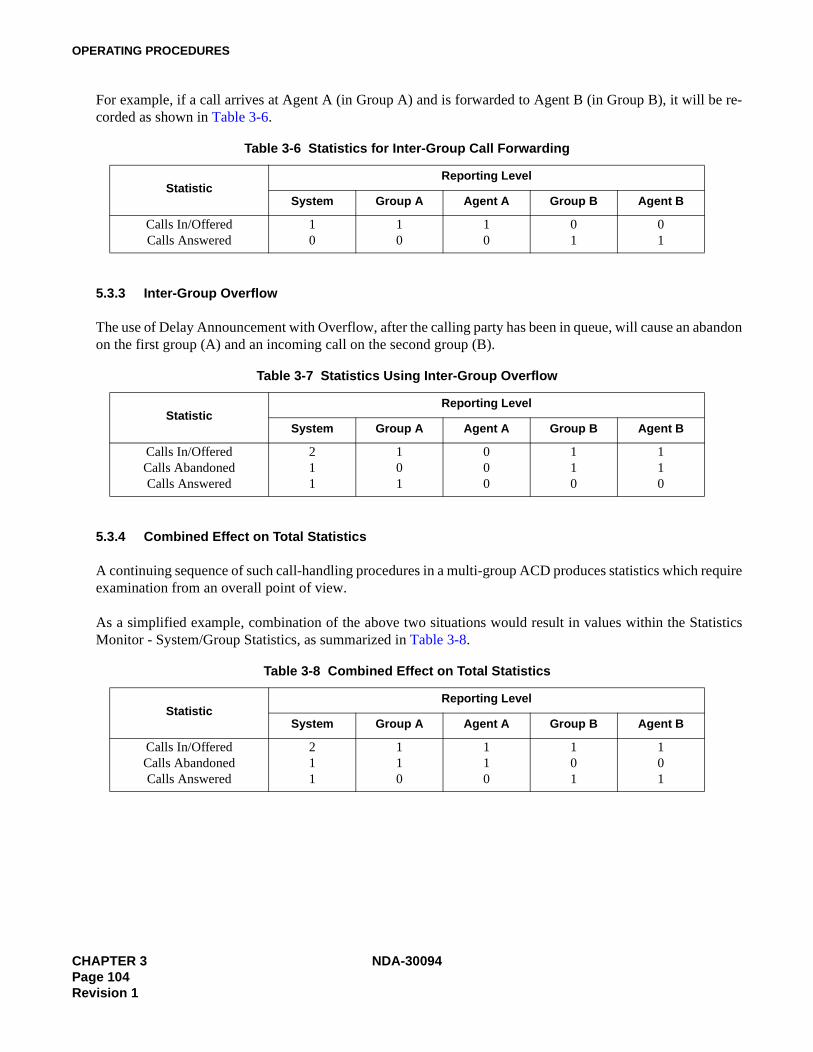
OPERATING PROCEDURES
For example, if a call arrives at Agent A (in Group A) and is forwarded to Agent B (in Group B), it will be re-corded as shown in Table 3-6.
5.3.3 Inter-Group Overflow
The use of Delay Announcement with Overflow, after the calling party has been in queue, will cause an abandonon the first group (A) and an incoming call on the second group (B).
5.3.4 Combined Effect on Total Statistics
A continuing sequence of such call-handling procedures in a multi-group ACD produces statistics which requireexamination from an overall point of view.
As a simplified example, combination of the above two situations would result in values within the StatisticsMonitor - System/Group Statistics, as summarized in Table 3-8.
Table 3-6 Statistics for Inter-Group Call Forwarding
StatisticReporting Level
System Group A Agent A Group B Agent B
Calls In/OfferedCalls Answered
10
10
10
01
01
Table 3-7 Statistics Using Inter-Group Overflow
StatisticReporting Level
System Group A Agent A Group B Agent B
Calls In/OfferedCalls AbandonedCalls Answered
211
101
000
110
110
Table 3-8 Combined Effect on Total Statistics
StatisticReporting Level
System Group A Agent A Group B Agent B
Calls In/OfferedCalls AbandonedCalls Answered
211
110
110
101
101
CHAPTER 3 NDA-30094Page 104Revision 1

OPERATING PROCEDURES
6. SYSTEM MAINTENANCE
From the Main Menu, press 3. The SYSTEM MAINTENANCE submenu displays.
This submenu has eight separate functions:
Password Maintenance: Control access to various system features
ACD Alarms: Display/print file record listing excesses of specified statistical lim-its.
System Message: Display/print file record listing system faults and occurrences
OAI Connection: Control MIS-PABX communication channel status
Configuration Data Backup: Copy general system, report, and alarm configuration data to floppydisk
EDU Port Selection: Assign required message formats to the various multi-I/O ports forthe External Display Units (where provided)
External Display Format: Select required message formats for the External Display Units
6.1 Passwords
From the System Maintenance submenu, press 1. The password set-up screen (with accommodation for 12 pass-words) will be displayed.
The first two passwords are preset in the basic system software:
• The first of these (//blank//) is fixed to the use of the Enter key at the Welcome Screen. Initially,it is set to allow very limited access to features; but that can be modified, if required.
• The second (mis) allows fixed unrestricted access to all features. Its name can be changed to oneof your choice.
NDA-30094 CHAPTER 3Page 105
Revision 1
OPERATING PROCEDURES
6.1.1 Review Existing Passwords
Step 1. Position the cursor within the brackets of the selected existing password.
Step 2. Press TAB. The access assignments for the Main Menu are displayed.
• Access status indications are:accessible = [y] (item color is white)inaccessible = [n] (item color is amber)
• Submenu indications are:[y> or [n> = submenu exists[y] or [n] = no associated submenu
Step 3. Position the cursor at an appropriate Main Menu item (i.e., one indicated with [y> and in white).Press TAB to display the related submenu.
Step 4. Repeat for all other similar items on the Main Menu.
6.1.2 Change / Delete Existing Password Details
Step 1. Position the cursor within the brackets of the password entry to be changed/deleted.
Observe the limitations on changing either of the two default passwords.
Step 2.
• Use the Arrow, DELETE, BACKSPACE, and INSERT keys to delete necessary existing charac-ters before retyping the new/modified password name. Upper- and lowercase letters are regardedseparately by the system.
• To completely delete the password, remove all characters (with the [Back Space] key). Go to Step8.
Step 3. Press TAB to display the current Main Menu access assignments.
Step 4. Position the cursor at each required item in turn and alter the current access status (i.e., enter y or n).
Step 5. Position the cursor at the first Main Menu item now indicated as [y> (but still in amber). Press TABto display the associated submenu.
Step 6. Make any necessary alterations as per Step 4.
Step 7. Return to the Main Menu (press SHIFT + TAB) and repeat the process for other items as required.
On return to the Main Menu, the color of an item which has been made accessible will have changedto white.
Step 8. At the appropriate point, press PAGE DOWN.
CHAPTER 3 NDA-30094Page 106Revision 1
OPERATING PROCEDURES
Step 9. Confirm your entries then press E, D, R, or C according to:
Execute = enter specified changes and escapeDefault = return to original screen display and repeat all entriesRedo = return to original screen display and repeat preferred entries onlyCancel = escape to menu without effecting any changes.
Note: For Default, any changes are lost; for Redo they are retained.
6.1.3 Add New Password
Step 1. Position the cursor at the selected vacant location within the passwords entry screen.
Step 2. Enter the new password (maximum 10 alphabetical characters).
Upper- and lowercase letters are regarded separately by the system.
Step 3. Press TAB to display the Main Menu.
Step 4. Enable access (i.e., enter y) to each required item in turn.
Step 5. Position the cursor at the first appropriate item (i.e. now marked [y> but still in amber). Press TABto display the associated submenu.
Step 6. Make any necessary alterations as per Step 4.
Step 7. Return to the Main Menu (press SHIFT + TAB) and repeat these last two procedures for all otheritems.
On return to the main Menu, the color of an item which has been made accessible will have changedto white.
Step 8. Confirm your entries. Then press E, D, R, or C according to:
Execute = enter specified changes and escapeDefault = return to original screen display and repeat all entriesRedo = return to original screen display and repeat preferred entries onlyCancel = escape to menu without effecting any changes
Note: For Default, any changes are lost but for Redo they are retained.
The message New Password File created appears whenever alterations and assignments arefinally executed to indicate successful entry of the new data into memory.
NDA-30094 CHAPTER 3Page 107
Revision 1
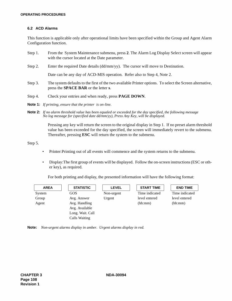
OPERATING PROCEDURES
6.2 ACD Alarms
This function is applicable only after operational limits have been specified within the Group and Agent AlarmConfiguration function.
Step 1. From the System Maintenance submenu, press 2. The Alarm Log Display Select screen will appearwith the cursor located at the Date parameter.
Step 2. Enter the required Date details (dd/mm/yy). The cursor will move to Destination.
Date can be any day of ACD-MIS operation. Refer also to Step 4, Note 2.
Step 3. The system defaults to the first of the two available Printer options. To select the Screen alternative,press the SPACE BAR or the letter s.
Step 4. Check your entries and when ready, press PAGE DOWN.
Note 1: If printing, ensure that the printer is on-line.
Note 2: If no alarm threshold value has been equaled or exceeded for the day specified, the following message No log message for (specified date dd/mm/yy), Press Any Key, will be displayed.
Pressing any key will return the screen to the original display in Step 1. If no preset alarm thresholdvalue has been exceeded for the day specified, the screen will immediately revert to the submenu.Thereafter, pressing ESC will return the system to the submenu.
Step 5.
• Printer:Printing out of all events will commence and the system returns to the submenu.
• Display:The first group of events will be displayed. Follow the on-screen instructions (ESC or oth-er key), as required.
For both printing and display, the presented information will have the following format:
Note: Non-urgent alarms display in amber. Urgent alarms display in red.
AREA STATISTIC LEVEL START TIME END TIME
System GOS Non-urgent Time indicated Time indicatedGroup Avg. Answer Urgent level entered level enteredAgent Avg. Handling (hh:mm) (hh:mm)
Avg. AvailableLong. Wait. CallCalls Waiting
CHAPTER 3 NDA-30094Page 108Revision 1
OPERATING PROCEDURES
6.3 System Messages
Step 1. From the System Maintenance submenu, press 3. The following message will display:
Print errors on printer? (y/n):
Step 2. Enter your requirement (y or n) according to:
• For y (yes), printing of all records will immediately commence after which the display will returnto the submenu.
Note: Ensure that the printer is on-line.
• For n (no), the System Message List screen will appear to display the applicable period of report-ing, the total number of messages recorded, and the first listings in reverse chronological order, fol-lowed by the further request:
Read the next errors? (y/n):
Enter your requirement (y or n) according to:
• For y (yes), the next page of messages will be displayed and the request repeated. The action canbe continued until a return display of the first page of listings.
• For n (no), the display will immediately return to the submenu.
6.4 OAI Connection
Step 1. From the System Maintenance submenu, press 4.
Depending on the current status, one of the following two messages will display:
The current status is always displayed on the left-hand side of the amber banner at the top of thescreen.
Step 2. Enter your requirement (y for yes or n for no). The display will revert to the submenu.
There will be a slight delay when connecting to the PABX.
Current Status Message
Off Connect to PABX (y/n):
On Disconnect from PABX (y/n):
NDA-30094 CHAPTER 3Page 109
Revision 1
OPERATING PROCEDURES
6.5 Configuration Data Backup
This feature enables files applicable to general configuration of the ACD-MIS to be saved to a floppy disk in-serted in the Floppy Drive. In the event that a major fault requires the system to be rebuilt, those files can thenbe copied back to the hard disk once the ACD-MIS program has been re-installed.
A 5 1/4", 1.2Mb or 3 1/2”, 1.44 Mb High Density floppy disk is required for the purpose. The relevant files arefor:
System PasswordsCommunications Port ParametersSystem NameGroup and Agent Statistics ThresholdsAgent ConfigurationACD Group ConfigurationReport ConfigurationReport Group ConfigurationReport Schedules (two files)Agent ID Codes
6.5.1 Back Up Files
Step 1. Login to ACDMIS user directory at UNIX login prompt. ACDMIS will run automatically.
Step 2. When asked for terminal type (keyboard type and display color/monochrome), press CTRL-C.
Step 3. Insert a formatted disk into the floppy Drive. Ensure that it is correctly locked in.
Step 4. At UNIX prompt, enter:
sh backup.sh
Step 5. Wait for the command to completed.
Step 6. At UNIX prompt, enter:
exit
to logoff.
CHAPTER 3 NDA-30094Page 110Revision 1
OPERATING PROCEDURES
6.5.2 Reload Files
Step 1. Login to ACDMIS user directory at UNIX login prompt. ACDMIS will run automatically.
Step 2. When asked for terminal type (keyboard type and display color/monochrome), press CTRL-C.
Step 3. Insert a formatted disk into the floppy Drive. Ensure that it is correctly locked in.
Step 4. At UNIX prompt, enter:
sh reload.sh
Step 5. Wait for the command to completed.
Step 6. At UNIX prompt, enter
exit
to logoff.
6.6 EDU Port Selection
This function assigns installed External Display Units (EDUs) to the individual Ports on the I/O board. The ac-tual selection of display formats is arranged in Item 8 - External Display Format.
Step 1. From the System Maintenance submenu, press 7. The Communications Port Assignment screen dis-plays. The available assignment options are listed at the bottom of the screen.
For a new system all ports will be set to the default selection NONE.
For an existing system with the EDU feature, the current assignments will be shown.
The available options are identified as:
EDU 1 - EDU 4: External Display Units 1 - 4Spectrum/Dataline: EDU typeTTY Device Name: /dev/tty as defined by System Administrator for the Comm Port.
Step 2. At whichever of Ports is to be set/modified first (move the cursor as required), use the SPACE BARto toggle selection of the required option or press the indicated digit (1 to 4 or the letter n.)
Step 3. Use the TAB key to move the cursor to the next selection, and use the SPACE bar to toggle selectionof Spectrum or Dataline; or press the indicated key (D for Dataline, S for Spectrum, or N for None.)
Step 4. Move the cursor to each next port to be set/modified, in turn and select as above.
Step 5. Confirm all assignments. Then press PAGE DOWN. The system returns to the submenu.
NDA-30094 CHAPTER 3Page 111
Revision 1

OPERATING PROCEDURES
6.7 External Display Format
The External Display Format submenu lets you specify:
• The choice of display format for each EDU• The relevant ACD group(s) for each format
Examples of display formats are included in Chapter 1.
The individual assignments made are identified as EDU 1 to 4 which correspond to the separate display panelsassigned to Ports on the I/O board in Item 7 - Auxiliary Port Selection.
Any format can be displayed on any panel. Even the same one can be displayed on all panels, if required.
Step 1. From the System Maintenance submenu, press 8. The External Display Format screen appears withthe cursor located ready for selection of the first format. The available message options are listedat the bottom of the screen.
For a new system, all formats will be set to the not used default selection. For an existing systemwith the EDU feature, the current selections for EDU 1 - 4 will instead be shown together with thepilot extension numbers of the associated ACD group(s).
The available display format options are identified as:
not used: provides a blank display on any specified panel
number: displays the current number of calls waiting in each of a maximum of seven (7)ACD groups
number time: displays the current number of waiting calls and the longest waiting time for eachof a maximum of two (2) ACD groups
name, no., time: displays the group name, the number of waiting calls and the longest waitingtime for one (1) ACD group.
Step 2. At whichever of EDU 1 - 4 is to be set/modified first (move the cursor as required), use the SPACEBAR to toggle selection of the required format option or press the indicated letter n, A, B, or C.
Step 3. Press TAB (or ENTER) to move the cursor to the first position within ACD Group Number, on thesame line.
There are seven (7) ACD Group Number positions per line. For a new system, all will be blank.For an existing system with the EDU feature, the current selections of pilot extension number aredisplayed together with blanks in all vacant positions.
CHAPTER 3 NDA-30094Page 112Revision 1
OPERATING PROCEDURES
Step 4. Use the SPACE BAR to toggle selection of the required pilot extension number Then press EN-TER to move the cursor to the next position.
If during initial assignment, the position is not to be used, simply press ENTER directly. None willbe displayed and the cursor will move to the next position. For later modification, toggle the selec-tion of the none option first.
(“None” means that the display field for the particular ACD group position on any associated EDUwill be blank.)
Step 5. Repeat for all other positions on the same line, observing the maximum allowed number of entries(7, 2, or 1) according to the selection originally made for the display format.
• Use SHIFT + TAB to move the cursor in the reverse direction, as required.
• If fewer than 7 entries are to be made, they can occupy any position:
Format ACD Group Number
1 2 3 4 5 6 7number 1234 none 2345 none 3456 none 4567
Step 6. Continue until the cursor moves to the next format line. Adjust its location as required.
Step 7. Repeat the procedures in Steps 2 to 6 to complete all necessary reassignments.
Step 8. Confirm your entries; then press PAGE DOWN. The system will return to the submenu.
NDA-30094 CHAPTER 3Page 113
Revision 1

OPERATING PROCEDURES
7. SYSTEM CONFIGURATION
From the Main Menu, press 4.The SYSTEM CONFIGURATION submenu displays.
This submenu includes eight functions:
System Name: For display on all screensGroup Configuration: Individual ACD groupsStation Configuration: Associated stationsAgent Configuration: Associated agentsACD Key Configuratio: Assigns MSF to LEDsReport Time Values : Time limit parameters for the Statistics Monitor mode and particular reportsStorage Intervals: Variable time intervals for statistics processing in particular reportsSystem Date Format: Changes the date format
7.1 System Name
System Name can be a maximum of any 40 characters, including spaces.
Step 1. From the System Configuration submenu, press 1. The System Name Assignment screen will dis-play.
Step 2. Depending on the action to be taken, proceed according to the following alternatives:
• Initial Name Assignment
Type in the preferred name characters and press PAGE DOWN. (The system will return to the submenu.)
• Current Name Modification
Using the ←, BACK SPACE, DELETE, and INSERT keys to erase, overwrite and add existingand new characters as required, enter the new preferred name. Then press PAGE DOWN. Thesystem will return to the submenu.
Step 3. Check for immediate appearance of the (new/modified) system name at the top of the displayscreen. It will also be printed at the head of each report page.
CHAPTER 3 NDA-30094Page 114Revision 1
OPERATING PROCEDURES
7.2 Group Configuration
Step 1. From the System Configuration submenu, press 2. The Group Configuration screen will display,with the cursor located at Group Name #01.
In the case of an existing MIS, first check the right-hand column for the current assignments indi-cated as:
- new group = unassigned (vacant) area- in use = existing, fully assigned group- not used = existing ACD group without agents assigned
Note: At the time of initial ACD-MIS set-up, the indicated status of all ACD groups will be new group.
Step 2. Depending on the action to be taken, proceed according to the following alternatives:
• New Group Assignment
Move the cursor to the first vacant location and type in the preferred group name.
• Existing Group Modification
Move the cursor to the applicable location and using the Arrow, DELETE, BACK SPACE, andINSERT keys, delete the required characters then retype the new Group Name characters. (Groupname can be a maximum of any 11 characters.)
• Existing Group Deletion
Go to Step 4.
Note: Before deleting an ACD group, delete the pilot number and all assigned agents.
Step 3. Press TAB to move the cursor to the Indial No. - prfx column and proceed according to the follow-ing alternatives:
• New Group Assignment
Type in the specified indial digits for the ACD group.
• Existing Group Modification
Use the Arrow, DELETE, BACK SPACE, and INSERT keys to delete the required digits. Thenretype the new Indial No. - prfx digits.
NDA-30094 CHAPTER 3Page 115
Revision 1
OPERATING PROCEDURES
Step 4. Press TAB to move the cursor to the Indial No. - ext. column and proceed according to the followingalternatives:
• New Group Assignment
Type in the specified pilot extension number.• Existing Group Modification
Use the Arrow, DELETE, BACK SPACE, and INSERT keys to delete the required digits then re-type the new pilot extension digits.
In most situations the pilot extension will be a phantom number. It can be a physical extension; butif so, it must not receive direct calls.
• Existing Group Deletion
Use BACK SPACE to delete all digits of the pilot number; then go to Step 6.
Step 5. If required, move the cursor to the next Group Name positions in turn (TAB and ENTER keys) andrepeat the above steps for any necessary entries/alterations/deletions.
Note: Only when Group Names #01 to #10 are entered can #11 to #16 (on the next screen) be used.
Note: After deletion of any group(s), the system will automatically adjust the positions of the others to close thegaps.
Step 6. Press PAGE DOWN to confirm all details and exit to the submenu.
7.3 Station Configuration
Step 1. From the System Configuration submenu, press 3. The Station Configuration screen will be dis-played, with the cursor located at Ext. No.
Step 2. Type in the required (first) extension number; then press ENTER.
The cursor will move to Tenant No.
• There is no requirement to enter extensions (including the pilot number) in any particular orderduring initial ACD group assignment.
• The specified extension number must be the Prime Line of a Dterm instrument which the agent uses(where installed) for the position to be able to log off and for certain report statistics to correspondto definition.
CHAPTER 3 NDA-30094Page 116Revision 1
OPERATING PROCEDURES
Step 3. Depending on the intended action, proceed according to the following alternatives:
• New Station Assignment
Check for display of the Add Station message which indicates that the extension number specifiedhas not been assigned.
Enter the required tenant number and press ENTER. The cursor will move to Tel. Type.
Note: The tenant number must always be the value for the ACD group set within the PABX.
• Existing Station Modification
Check for the display of the station exists and Modify Station messages and also the current assign-ments for all other parameters.
Move the cursor (down) in turn to each entry to be altered. Make necessary adjustments to exten-sion number digits or surname characters (by positioning the cursor and using the DELETE,BACK SPACE, and INSERT keys) and as otherwise described in Steps 4 - 5, then go to Step 8.
• Existing Station Deletion
Press ENTER. The cursor will move to the currently displayed Modify Station option. Select theDelete Station option by toggling the SPACE BAR or pressing the indicated letter d.
Go to Step 8.
Step 4. For either initial specification or later modification, use the SPACE BAR to change selection ofTel. Type or press the indicated letter a - e, as required. The five options are displayed at the bottomof the screen.
Press ENTER. The cursor will move to group.
The specified Tel. Type must be selected as one only of:
• The actual telephone instrument installed for the particular agents position (option a or b)• The pilot number specified in the PBX (option c, d, or e)
Step 5. Similarly, specify/modify the associated ACD group by selecting the required Indial - prfx from thelisting at the bottom of the screen.
Step 6. Check all specifications and when ready, press PAGE DOWN to confirm the entered details. Thesystem will revert to the submenu.
Step 7. Repeat Steps 1 - 6 above for all remaining required station assignments or modifications.
NDA-30094 CHAPTER 3Page 117
Revision 1
OPERATING PROCEDURES
7.4 Agent Configuration
Step 1. From the System Configuration submenu, press 4. The Agent Configuration screen will display,with the cursor located at Agent ID.
Step 2. Type in the required ID code; then press ENTER.
Note: There is a system limitation of 90 Agent ID codes which can be programmed in ACD-MIS. The cursor willmove to Agent Name.
Step 3. Type in the Agent’s last name; press ENTER.
The cursor will move to Agent Initial.
Step 4. Type in the Agent’s first name initial(s); press ENTER.
The cursor will move to Group.
Step 5. Select the ACD group to which the agent can log in. Select using either the Space Bar or the letterdesignation of the group.
Step 6. Check all specifications. When ready, press PAGE DOWN to confirm the entered details. The sys-tem will revert to the submenu.
Step 7. Repeat Steps 1-6 for all remaining agent assignments.
7.5 ACD Key Configuration
Step 1. From the System Configuration submenu, press 5. The ACD Key Configuration screen will display,with the cursor located at Log On/Off (MSF no.).
Step 2. Type the MSF Operation Code 128 for Log On/Off; then press ENTER.
The cursor will move to LED no.
Step 3. Type in the LED no. that the MSF (Log On/Off) will appear on the Dterm; press ENTER. The cursorwill move to Break Key.
Step 4. Type the MSF Operation Code 129 for Break; press ENTER.
The cursor will move to LED no.
Step 5. Type in the LED no. that the MSF (Break) will appear on the Dterm; press ENTER.
The cursor will move to the Work Key.
Step 6. Type the MSF Operation Code 130 for Work; press ENTER.
Led cursor will move to LED no.
CHAPTER 3 NDA-30094Page 118Revision 1
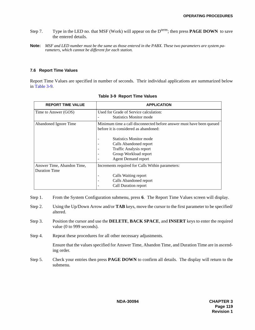
OPERATING PROCEDURES
Step 7. Type in the LED no. that MSF (Work) will appear on the Dterm; then press PAGE DOWN to savethe entered details.
Note: MSF and LED number must be the same as those entered in the PABX. These two parameters are system pa-rameters, which cannot be different for each station.
7.6 Report Time Values
Report Time Values are specified in number of seconds. Their individual applications are summarized belowin Table 3-9.
Step 1. From the System Configuration submenu, press 6. The Report Time Values screen will display.
Step 2. Using the Up/Down Arrow and/or TAB keys, move the cursor to the first parameter to be specified/altered.
Step 3. Position the cursor and use the DELETE, BACK SPACE, and INSERT keys to enter the requiredvalue (0 to 999 seconds).
Step 4. Repeat these procedures for all other necessary adjustments.
Ensure that the values specified for Answer Time, Abandon Time, and Duration Time are in ascend-ing order.
Step 5. Check your entries then press PAGE DOWN to confirm all details. The display will return to thesubmenu.
Table 3-9 Report Time Values
REPORT TIME VALUE APPLICATION
Time to Answer (GOS) Used for Grade of Service calculation:- Statistics Monitor mode
Abandoned Ignore Time Minimum time a call disconnected before answer must have been queued before it is considered as abandoned:
- Statistics Monitor mode- Calls Abandoned report- Traffic Analysis report- Group Workload report- Agent Demand report
Answer Time, Abandon Time, Duration Time
Increments required for Calls Within parameters:
- Calls Waiting report- Calls Abandoned report- Call Duration report
NDA-30094 CHAPTER 3Page 119
Revision 1
OPERATING PROCEDURES
7.7 Storage Intervals
Step 1. From the System Configuration submenu, press 7. The Storage Intervals screen will display.
The displayed table comprises hourly time segments from 0000 to 2359 and for each, a correspond-ing 60-minute (default) interval for call record storage. These intervals can be made more regular.Their application is in the presentation of statistics for specified reports where the selected optionfor report breakdown is by period.
Step 2. Using the Up/Down Arrow keys, move the cursor to the first time segment to be altered.
Step 3. Select the required alternative interval from the options shown at the bottom of the screen by tog-gling with the SPACE BAR or pressing the indicated letter a, b, c, etc.
Call records will be processed for storage at a frequency corresponding to the selected interval [e.g.,three times per hour if the value set is 20 (minutes)].
Step 4. Repeat these procedures for all other necessary time segment changes.
Step 5. Check your entries then press PAGE DOWN to confirm all details. The display will return to thesubmenu.
7.8 System Date Format
Step 1. From the System Configuration submenu, press 8. The System Date Format screen will display,with the cursor located at the System Date Format to be used.
Step 2. Select the date format to be used.
Step 3. Check the format. When ready, press PAGE DOWN to confirm the entered format.
CHAPTER 3 NDA-30094Page 120Revision 1

OPERATING PROCEDURES
8. ALARM CONFIGURATION
From the Main Menu, press 5. The ALARM CONFIGURATION submenu will display.
This submenu has four functions:Group Statistics Threshold: Presetting of alarm limits for both the system and ACD group related
parameters
Agent Statistics Threshold: Presetting of similar alarm limits for the agent related parameters
Print Thresholds: Printing out of the current status of both the System/Group and AgentStatistics configurations
Audible Alarm Period: Setting the period of the audible alarm associated with the StatisticsMonitor Mode - System/Group Statistics Longest Waiting Call param-eter
Note: Alarm conditions are also recorded in the ACD Alarm file.
8.1 Group Statistics Threshold
Step 1. From the Alarm Configuration submenu, press 1. The Group Alarms set up screen will display.
Step 2. Use the Up/Down Arrow and TAB keys to move the cursor between parameters for both initialspecification and later alteration.
For each entry, position the cursor and use the DELETE, BACK SPACE, and INSERT keys tofacilitate adjustment of the required value as per the following descriptions.
When the value to be entered is greater than 10, you must first erase the default value.
System/Group Statistics - G.O.S. - Low/High Alarms:
G.O.S. (Grade of Service) is the calculated percentage value used to indicate ACD call handlingefficiency. The respective settings for the low and high alarms must therefore correspond to a de-scending order of G.O.S. Refer to the example below:
Assumed Target G.O.S.: 90 %Low Alarm Setting: 70(%)High Alarm Setting: 50(%).
System/Group Statistics - Average Answer, Average Talk, Average Available, and LongestWaiting Call - Low/High Alarms:
Average Answer, Average Talk, Average Available, and Longest Waiting Call are direct time mea-surements (in minutes and seconds) related to call handling. The respective settings for the low andhigh alarms must be in ascending order.
NDA-30094 CHAPTER 3Page 121
Revision 1

OPERATING PROCEDURES
System/Group Statistics - Calls Waiting - Low/High Alarms:
Calls Waiting is a numerical quantity (in the range: 0 - 999) for indication of the call queue status.Settings of low and high alarms are also to be assigned in ascending order.
Step 3. Check your entries and when appropriate, press PAGE DOWN to confirm all details. The screenwill return to the submenu.
8.2 Agent Statistics Threshold
Step 1. From the Alarm Configuration submenu, press 2. The Agent Alarms set-up screen will display.
Step 2. For both initial specification and later alteration, use the Up/Down Arrow and TAB keys to movethe cursor between each parameter. To enter a value, position the cursor and use the DELETE,BACK SPACE, and INSERT keys to facilitate adjustment. Refer to the following descriptions.
When the value to be entered is greater than 10, you must first erase the default value.
Group Statistics - Average Answer, Average Talk, and Average Available - Low/High Alarms:
Average Answer, Average Talk, and Average Available are direct time measurements (in minutesand seconds) related to call handling. The respective settings for the low and high alarms must bein ascending order.
The parameters Max Talk, Max. Available, Max. O/G, and Max. Logged Off have no application inthe present version of ACD-MIS and are therefore omitted.
Step 3. Check your entries and when appropriate, press PAGE DOWN to confirm all details.
The screen will return to the submenu.
8.3 Print Thresholds
From the Alarm Configuration submenu, press 3 to initiate direct printing.
Note: If action is prevented because of a problem with the printer, an appropriate warning message will be givenat the top of the screen (in the red banner) :
Printer not on line: Retry (Y/N) ?
CHAPTER 3 NDA-30094Page 122Revision 1
OPERATING PROCEDURES
8.4 Audible Alarm Period
The alarm warning tone associated with the high value of the Statistics Monitor - System and Group StatisticsWaiting Longest parameter can be set to be repeated every 5, 10, 20, 30, 60 or 90 seconds or disabled altogether,by this function.
Any adjustment made has an immediate effect, even if the warning tone is currently being produced.
Step 1. From the Alarm Configuration submenu, press 4. The Audible Alarm Period set-up screen is dis-played with the cursor located ready for entry of the preferred value.
(The “none” default setting means the feature is disabled.)
Step 2. For either initial assignment or later alteration, toggle the SPACE BAR to select the required periodor alternatively press the indicated digit 1 to 6.
Step 3. Confirm your selection and press PAGE DOWN.
The system will return to the submenu.
NDA-30094 CHAPTER 3Page 123
Revision 1

OPERATING PROCEDURES
9. SYSTEM EXIT
Step 1. Check for current printing of any reports.
Step 2. From the Main Menu, select Item 3 - System Maintenance. The SYSTEM MAINTENANCE sub-menu will display.
Step 3. Select Item 4 - OAI Connection.
The Disconnect from PBX (y/n) message will be displayed.
Step 4. Type y. The Checking Communications Status. Please wait message will be displayed.
Wait for the system to return to the sub menu then ensure connection status indicates OAI off.If you decide not to proceed, type n (no). The display will immediately return to the Main Menu.
Step 5. Press ESC. The system will return to the Main Menu.
Step 6. Press 6. The following message will display:
You are about to close down the system.When you do this, the system will stop receiving ACD statistics.
Do you wish to stop the system (y/n):?
Step 7. Press 6. The following messages will display:
Closing down the system.External display terminated....Saving call data.... Please wait.Call data save completed....
This will eventually be replaced by the $ prompt.
<<<<<<WARNING>>>>>>
SYSTEM EXIT completely shuts down the MIS and returns the PC to the operating system. Inthat mode:
1.The Statistics Monitor mode will be initialized.2.No new ACD call data can be received from the PBX and processed.3.Any reports scheduled during the period of shut-down will not be printed.
CHAPTER 3 NDA-30094Page 124Revision 1

CUSTOMER SPECIFICATIONS
CHAPTER 4 CUSTOMER SPECIFICATIONS
1. SYSTEM CONFIGURATION
1.1 Group Configuration
• A maximum of 16 ACD groups can be specified.
• Group name can be a maximum of 11 alphanumeric characters.
• The nominated pilot is usually a phantom extension. It can be a physical extension, but it must not receivedirect calls.
Table 4-1 ACD Group Configuration Table
ACD group Indial No.
No. Name Prefix Pilot ext.
01
02
03
04
05
06
07
08
09
10
11
12
13
14
15
16
NDA-30094 CHAPTER 4Page 125
Revision 1

CUSTOMER SPECIFICATIONS
1.2 Agent Configuration
• A maximum of 60 extensions can be assigned per ACD group.
• Extensions (including the pilot number) can be entered in any order.
• Tenant No. must be the value set for the ACD group within the PABX.
• Where preferred, the entry for Agent Name can be other than a surname (e.g., Agent 1). Each entry mustbe a maximum of 11 characters, including spaces.
PHOTOCOPY AS REQUIRED:
Agent Configuration Table
Table 4-2 Agent Configuration Table
TENANT NO.:
...............................
GROUP NAME: ......................................
GROUP No.: .......................................
AGENT ID CODE
AGENT (SUR)NAMEAGENTINITIAL
1
2
3
4
5
6
7
8
9
10
11
12
13
14
15
CHAPTER 4 NDA-30094Page 126Revision 1
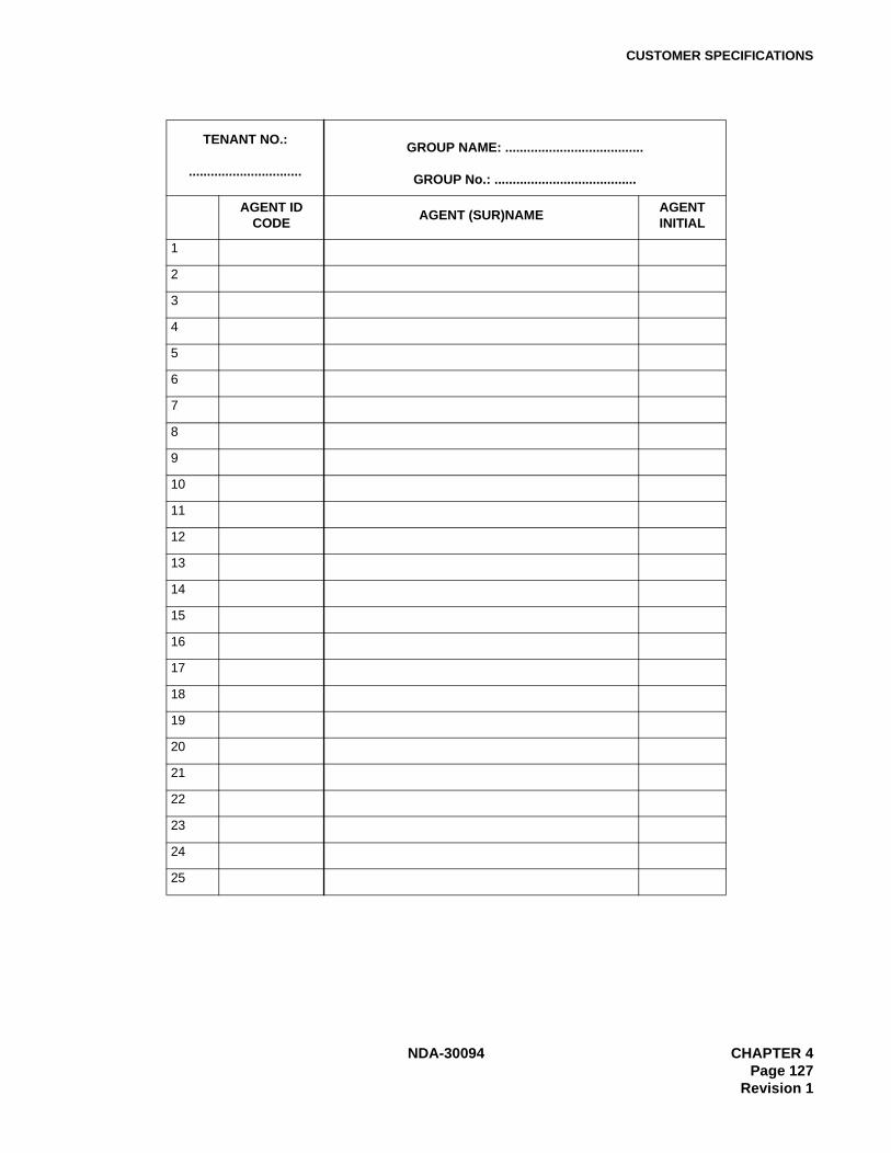
CUSTOMER SPECIFICATIONS
TENANT NO.:
...............................
GROUP NAME: ......................................
GROUP No.: .......................................
AGENT ID CODE
AGENT (SUR)NAMEAGENTINITIAL
1
2
3
4
5
6
7
8
9
10
11
12
13
14
15
16
17
18
19
20
21
22
23
24
25
NDA-30094 CHAPTER 4Page 127
Revision 1

CUSTOMER SPECIFICATIONS
1.3 Report Time Values
• Terms are defined as follows:• Time to Answer refers to G.O.S. calculation.• Abandoned Ignore Time is the minimum required waiting time before disconnection for the call to be
considered as abandoned.• Answer Time, Abandon Time and Duration Time refer to the Calls Within parameters of the Calls Wait-
ing, Calls Abandoned, and Call Duration reports, respectively.
• Ensure that the values specified for Answer Time, Abandon Time, and Duration Time are in ascending or-der (see entries 1 - 5).
• All specifications are number of seconds in the range of 0 - 999.
Table 4-3 Report Time Values
TIME TO ANSWER: ABANDON IGNORED TIME:
ANSWER TIME: 1. 2. 3. 4. 5.
ABANDON TIME: 1. 2. 3. 4. 5.
DURATION TIME: 1. 2. 3. 4. 5.
CHAPTER 4 NDA-30094Page 128Revision 1

CUSTOMER SPECIFICATIONS
1.4 Storage Intervals
Table 4-4 Storage Intervals
SEGMENT INCREMENT SEGMENT INCREMENT
0000 - 0059 10 15 20 30 60 1200 - 1259 10 15 20 30 60
0100 - 0159 10 15 20 30 60 1300 - 1359 10 15 20 30 60
0200 - 0259 10 15 20 30 60 1400 - 1459 10 15 20 30 60
0300 - 0359 10 15 20 30 60 1500 - 1559 10 15 20 30 60
0400 - 0459 10 15 20 30 60 1600 - 1659 10 15 20 30 60
0500 - 0559 10 15 20 30 60 1700 - 1759 10 15 20 30 60
0600 - 0659 10 15 20 30 60 1800 - 1859 10 15 20 30 60
0700 - 0759 10 15 20 30 60 1900 - 1959 10 15 20 30 60
0800 - 0859 10 15 20 30 60 2000 - 2059 10 15 20 30 60
0900 - 0959 10 15 20 30 60 2100 - 2159 10 15 20 30 60
1000 - 1059 10 15 20 30 60 2200 - 2259 10 15 20 30 60
1100 - 1159 10 15 20 30 60 2300 - 2359 10 15 20 30 60
NDA-30094 CHAPTER 4Page 129
Revision 1
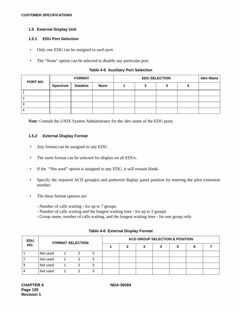
CUSTOMER SPECIFICATIONS
1.5 External Display Unit
1.5.1 EDU Port Selection
• Only one EDU can be assigned to each port.
• The “None“ option can be selected to disable any particular port.
Note: Consult the UNIX System Administrator for the /dev name of the EDU ports.
1.5.2 External Display Format
• Any format can be assigned to any EDU.
• The same format can be selected for display on all EDUs.
• If the “Not used” option is assigned to any EDU, it will remain blank.
• Specify the required ACD group(s) and preferred display panel position by entering the pilot extensionnumber.
• The three format options are:
- Number of calls waiting - for up to 7 groups- Number of calls waiting and the longest waiting time - for up to 2 groups- Group name, number of calls waiting, and the longest waiting time - for one group only.
Table 4-5 Auxiliary Port Selection
PORT NO.FORMAT EDU SELECTION /dev Name
Spectrum Dataline None 1 2 3 4
1
2
3
4
Table 4-6 External Display Format
EDUNO.
FORMAT SELECTIONACD GROUP SELECTION & POSITION
1 2 3 4 5 6 7
1 Not used 1 2 3
2 Not used 1 2 3
3 Not used 1 2 3
4 Not used 1 2 3
CHAPTER 4 NDA-30094Page 130Revision 1
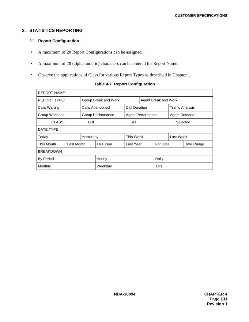
CUSTOMER SPECIFICATIONS
2. STATISTICS REPORTING
2.1 Report Configuration
• A maximum of 20 Report Configurations can be assigned.
• A maximum of 20 (alphanumeric) characters can be entered for Report Name.
• Observe the applications of Class for various Report Types as described in Chapter 1.
Table 4-7 Report Configuration
REPORT NAME:
REPORT TYPE: Group Break and Work Agent Break and Work
Calls Waiting Calls Abandoned Call Duration Traffic Analysis
Group Workload Group Performance Agent Performance Agent Demand
CLASS : Full All Selected
DATE TYPE
Today Yesterday This Week Last Week
This Month Last Month This Year Last Year For Date Date Range
BREAKDOWN
By Period Hourly Daily
Monthly Weekday Total
NDA-30094 CHAPTER 4Page 131
Revision 1

CUSTOMER SPECIFICATIONS
PHOTOCOPY AS REQUIRED:
Report Configuration
REPORT NAME:
REPORT TYPE: Group Break and Work Agent Break and Work
Calls Waiting Calls Abandoned Call Duration Traffic Analysis
Group Workload Group Performance Agent Performance Agent Demand
CLASS : Full All Selected
DATE TYPE
Today Yesterday This Week Last Week
This Month Last Month This Year Last Year For Date Date Range
BREAKDOWN
By Period Hourly Daily
Monthly Weekday Total
CHAPTER 4 NDA-30094Page 132Revision 1
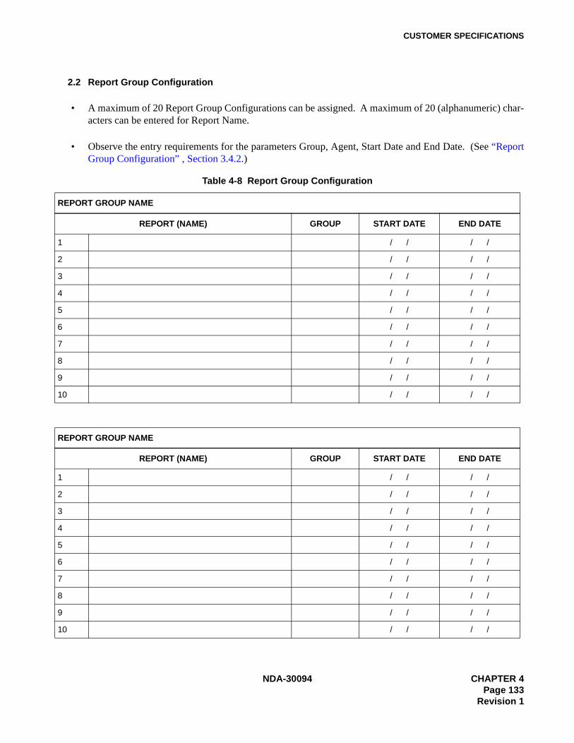
CUSTOMER SPECIFICATIONS
2.2 Report Group Configuration
• A maximum of 20 Report Group Configurations can be assigned. A maximum of 20 (alphanumeric) char-acters can be entered for Report Name.
• Observe the entry requirements for the parameters Group, Agent, Start Date and End Date. (See “ReportGroup Configuration” , Section 3.4.2.)
Table 4-8 Report Group Configuration
REPORT GROUP NAME
REPORT (NAME) GROUP START DATE END DATE
1 / / / /
2 / / / /
3 / / / /
4 / / / /
5 / / / /
6 / / / /
7 / / / /
8 / / / /
9 / / / /
10 / / / /
REPORT GROUP NAME
REPORT (NAME) GROUP START DATE END DATE
1 / / / /
2 / / / /
3 / / / /
4 / / / /
5 / / / /
6 / / / /
7 / / / /
8 / / / /
9 / / / /
10 / / / /
NDA-30094 CHAPTER 4Page 133
Revision 1

CUSTOMER SPECIFICATIONS
PHOTOCOPY AS REQUIRED:
Report Group Configuration
REPORT GROUP NAME
REPORT (NAME) GROUP START DATE END DATE
1 / / / /
2 / / / /
3 / / / /
4 / / / /
5 / / / /
6 / / / /
7 / / / /
8 / / / /
9 / / / /
10 / / / /
REPORT GROUP NAME
REPORT (NAME) GROUP START DATE END DATE
1 / / / /
2 / / / /
3 / / / /
4 / / / /
5 / / / /
6 / / / /
7 / / / /
8 / / / /
9 / / / /
10 / / / /
CHAPTER 4 NDA-30094Page 134Revision 1
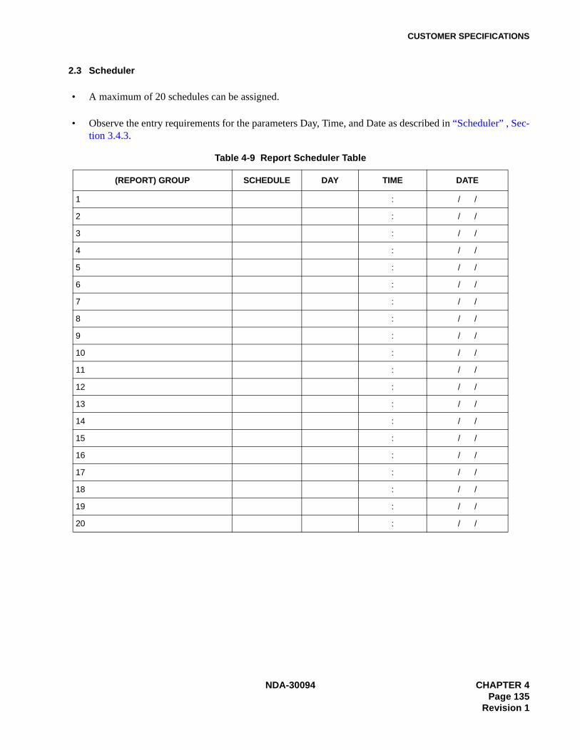
CUSTOMER SPECIFICATIONS
2.3 Scheduler
• A maximum of 20 schedules can be assigned.
• Observe the entry requirements for the parameters Day, Time, and Date as described in “Scheduler” , Sec-tion 3.4.3.
Table 4-9 Report Scheduler Table
(REPORT) GROUP SCHEDULE DAY TIME DATE
1 : / /
2 : / /
3 : / /
4 : / /
5 : / /
6 : / /
7 : / /
8 : / /
9 : / /
10 : / /
11 : / /
12 : / /
13 : / /
14 : / /
15 : / /
16 : / /
17 : / /
18 : / /
19 : / /
20 : / /
NDA-30094 CHAPTER 4Page 135
Revision 1
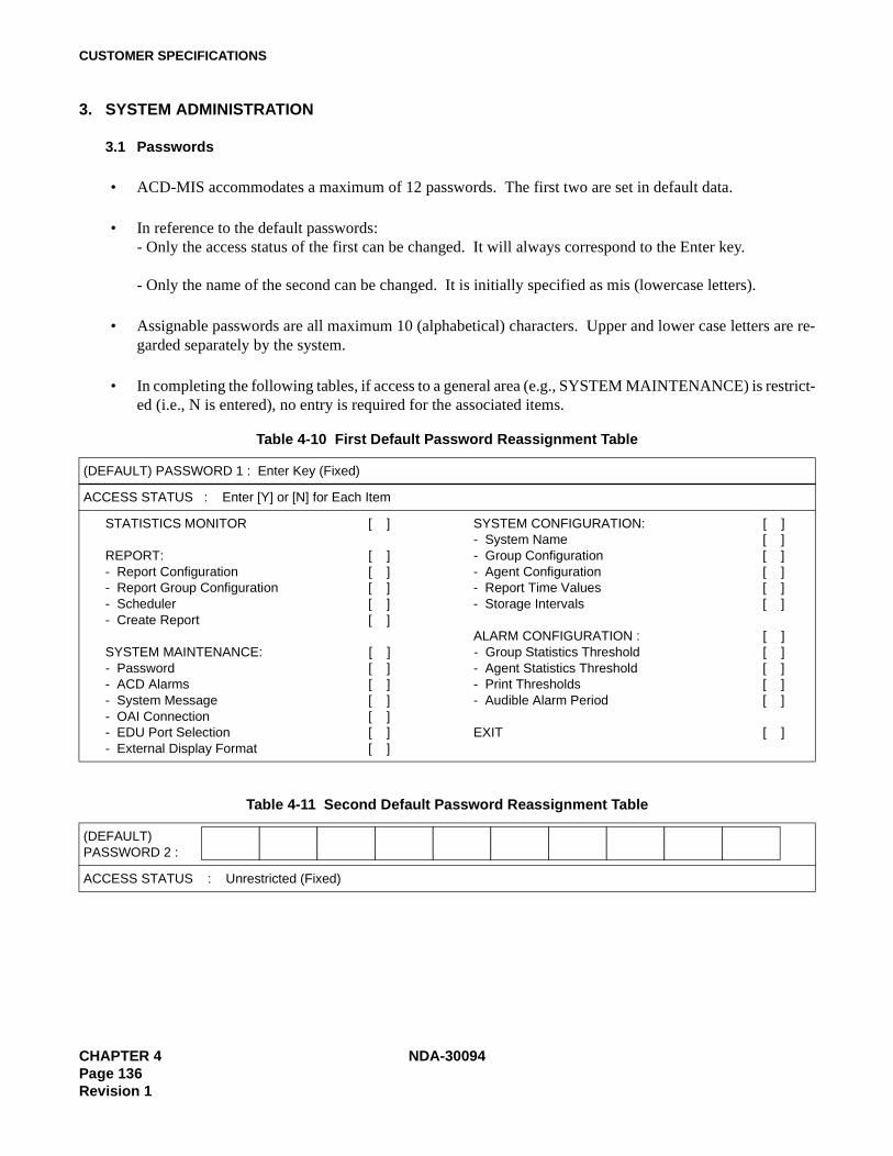
CUSTOMER SPECIFICATIONS
3. SYSTEM ADMINISTRATION
3.1 Passwords
• ACD-MIS accommodates a maximum of 12 passwords. The first two are set in default data.
• In reference to the default passwords:- Only the access status of the first can be changed. It will always correspond to the Enter key.
- Only the name of the second can be changed. It is initially specified as mis (lowercase letters).
• Assignable passwords are all maximum 10 (alphabetical) characters. Upper and lower case letters are re-garded separately by the system.
• In completing the following tables, if access to a general area (e.g., SYSTEM MAINTENANCE) is restrict-ed (i.e., N is entered), no entry is required for the associated items.
Table 4-10 First Default Password Reassignment Table
(DEFAULT) PASSWORD 1 : Enter Key (Fixed)
ACCESS STATUS : Enter [Y] or [N] for Each Item
STATISTICS MONITOR [ ] SYSTEM CONFIGURATION: [ ]- System Name [ ]
REPORT: [ ] - Group Configuration [ ]- Report Configuration [ ] - Agent Configuration [ ]- Report Group Configuration [ ] - Report Time Values [ ]- Scheduler [ ] - Storage Intervals [ ]- Create Report [ ]
ALARM CONFIGURATION : [ ]SYSTEM MAINTENANCE: [ ] - Group Statistics Threshold [ ]- Password [ ] - Agent Statistics Threshold [ ]- ACD Alarms [ ] - Print Thresholds [ ]- System Message [ ] - Audible Alarm Period [ ]- OAI Connection [ ]- EDU Port Selection [ ] EXIT [ ]- External Display Format [ ]
Table 4-11 Second Default Password Reassignment Table
(DEFAULT)PASSWORD 2 :
ACCESS STATUS : Unrestricted (Fixed)
CHAPTER 4 NDA-30094Page 136Revision 1

CUSTOMER SPECIFICATIONS
Table 4-12 New Password Assignment
PASSWORD 3 :
ACCESS STATUS : Enter [Y] or [N] for Each Item
STATISTICS MONITOR [ ] SYSTEM CONFIGURATION: [ ]- System Name [ ]
REPORT: [ ] - Group Configuration [ ]- Report Configuration [ ] - Agent Configuration [ ]- Report Group Configuration [ ] - Report Time Values [ ]- Scheduler [ ] - Storage Intervals [ ]- Create Report [ ]
ALARM CONFIGURATION : [ ]SYSTEM MAINTENANCE: [ ] - Group Statistics Threshold [ ]- Password [ ] - Agent Statistics Threshold [ ]- ACD Alarms [ ] - Print Thresholds [ ]- System Message [ ] - Audible Alarm Period [ ]- OAI Connection [ ]- EDU Port Selection [ ] EXIT [ ]- External Display Format [ ]
PASSWORD 4 :
ACCESS STATUS : Enter [Y] or [N] for Each Item
STATISTICS MONITOR [ ] SYSTEM CONFIGURATION: [ ]- System Name [ ]
REPORT: [ ] - Group Configuration [ ]- Report Configuration [ ] - Agent Configuration [ ]- Report Group Configuration [ ] - Report Time Values [ ]- Scheduler [ ] - Storage Intervals [ ]- Create Report [ ]
ALARM CONFIGURATION : [ ]SYSTEM MAINTENANCE: [ ] - Group Statistics Threshold [ ]- Password [ ] - Agent Statistics Threshold [ ]- ACD Alarms [ ] - Print Thresholds [ ]- System Message [ ] - Audible Alarm Period [ ]- OAI Connection [ ]- EDU Port Selection [ ] EXIT [ ]- External Display Format [ ]
NDA-30094 CHAPTER 4Page 137
Revision 1
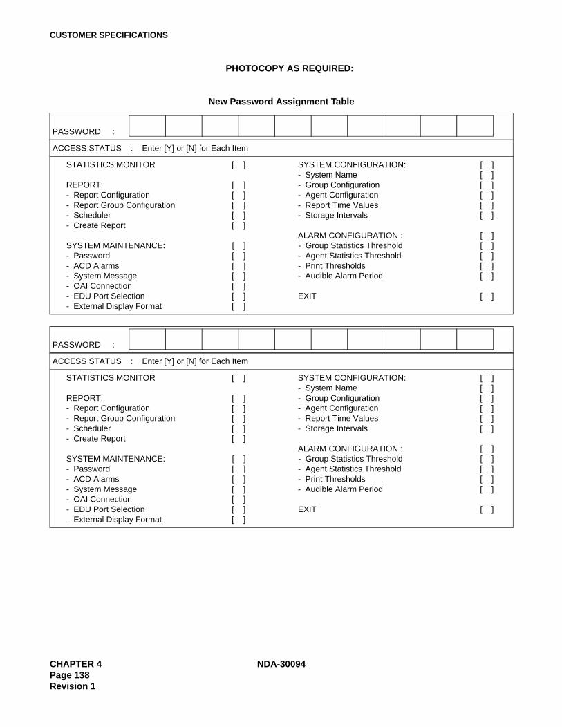
CUSTOMER SPECIFICATIONS
PHOTOCOPY AS REQUIRED:
New Password Assignment Table
PASSWORD :
ACCESS STATUS : Enter [Y] or [N] for Each Item
STATISTICS MONITOR [ ] SYSTEM CONFIGURATION: [ ]- System Name [ ]
REPORT: [ ] - Group Configuration [ ]- Report Configuration [ ] - Agent Configuration [ ]- Report Group Configuration [ ] - Report Time Values [ ]- Scheduler [ ] - Storage Intervals [ ]- Create Report [ ]
ALARM CONFIGURATION : [ ]SYSTEM MAINTENANCE: [ ] - Group Statistics Threshold [ ]- Password [ ] - Agent Statistics Threshold [ ]- ACD Alarms [ ] - Print Thresholds [ ]- System Message [ ] - Audible Alarm Period [ ]- OAI Connection [ ]- EDU Port Selection [ ] EXIT [ ]- External Display Format [ ]
CHAPTER 4 NDA-30094Page 138Revision 1
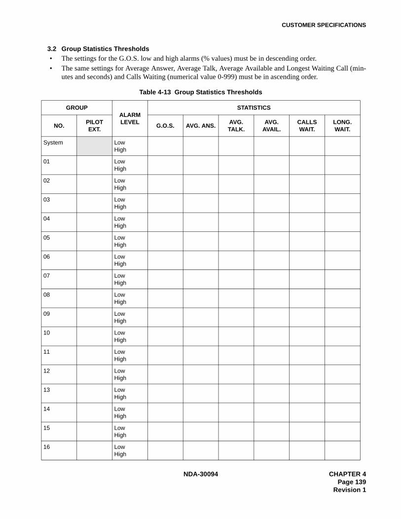
CUSTOMER SPECIFICATIONS
3.2 Group Statistics Thresholds• The settings for the G.O.S. low and high alarms (% values) must be in descending order.• The same settings for Average Answer, Average Talk, Average Available and Longest Waiting Call (min-
utes and seconds) and Calls Waiting (numerical value 0-999) must be in ascending order.
Table 4-13 Group Statistics Thresholds
GROUPALARM LEVEL
STATISTICS
NO.PILOTEXT.
G.O.S. AVG. ANS.AVG.TALK.
AVG. AVAIL.
CALLS WAIT.
LONG. WAIT.
System LowHigh
01 LowHigh
02 LowHigh
03 LowHigh
04 LowHigh
05 LowHigh
06 LowHigh
07 LowHigh
08 LowHigh
09 LowHigh
10 LowHigh
11 LowHigh
12 LowHigh
13 LowHigh
14 LowHigh
15 LowHigh
16 LowHigh
NDA-30094 CHAPTER 4Page 139
Revision 1

CUSTOMER SPECIFICATIONS
3.3 Agent Statistics Thresholds
The settings for Average Answer, Average Talk, and Average Available low and high alarms (minutes and sec-onds) must be in ascending order.
Table 4-14 Agent Statistics Thresholds
GROUPALARM LEVEL
STATISTICS
NO.PILOTEXT.
AVG. ANS.AVG.TALK.
AVG. AVAIL.
01 LowHigh
02 LowHigh
03 LowHigh
04 LowHigh
05 LowHigh
06 LowHigh
07 LowHigh
08 LowHigh
09 LowHigh
10 LowHigh
11 LowHigh
12 LowHigh
13 LowHigh
14 LowHigh
15 LowHigh
16 LowHigh
CHAPTER 4 NDA-30094Page 140Revision 1
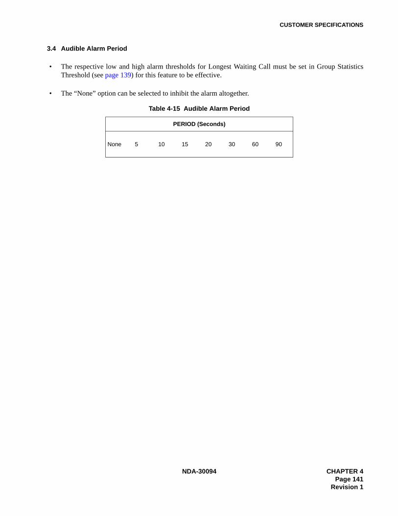
CUSTOMER SPECIFICATIONS
3.4 Audible Alarm Period
• The respective low and high alarm thresholds for Longest Waiting Call must be set in Group StatisticsThreshold (see page 139) for this feature to be effective.
• The “None” option can be selected to inhibit the alarm altogether.
Table 4-15 Audible Alarm Period
PERIOD (Seconds)
None 5 10 15 20 30 60 90
NDA-30094 CHAPTER 4Page 141
Revision 1

CUSTOMER SPECIFICATIONS
CHAPTER 4 NDA-30094Page 142Revision 1

ACD-MIS TERMINAL USER GUIDE
APPENDIX A ACD-MIS TERMINAL USER GUIDE (Real Time Statistic Screen)
LOG ON (Multiline Display Terminal)With telephone idle and handset on hook:
• Real Time Statistic screen on MIS PC shows “LOGGED OFF” with your extension number.• Log On/Off key LED is dark.• Press Log On/Off key. Log On/Off key LED flash red at 120 ipm.• LCD display shows “Enter ID:”• Dial ID number followed by #.• Terminal chimes twice. Log On/Off LED is green. The terminal displays “LOG ON” momentarily.• Real Time Statistic screen on MIS PC shows “AVAILABLE” with your designation and extension number.
LOG ON (Single Line and Multiline Non Display Terminal)With telephone idle and handset on hook:
• Real Time Statistic screen on MIS PC shows “LOGGED OFF” with your extension number.• Lift handset. If using headset with non display terminal, press Headset/Handset key. Note 1
• Receive dial tone and dial Log On/Off Feature Access Code.• Receive Feature Dial Tone and dial ID number, followed by#.• Receive Feature Set Tone.• Replace handset. If using headset with non display terminal, press Headset/Handset key. Note 1
• Real Time Statistic screen on MIS PC shows “AVAILABLE” with your designation and extension number.
ANSWERING ACD CALLS (Calls Directed at Pilot of ACD Group)Receive incoming ring signal:
• Real Time Statistic screen on MIS PC shows “ACD RINGING” with your designation and extension num-ber.
• Lift handset. If using headset with display or non display terminal, press Headset/Handset key. Note 1
• Converse• Real Time Statistic screen on MIS PC shows “ACD CALL” with your designation and extension number.
ANSWERING NON-ACD CALLS (Calls Directed at Available Agent Station)Receive incoming ring signal:
• Real Time Statistic screen on MIS PC shows “NON ACD” with your designation and extension number.• Lift handset. If using headset with display or non display terminal, press Headset/Handset key. Note 1
• Converse• Real Time Statistic screen on MIS PC shows “NON ACD” with your designation and extension number.
NDA-30094 APPENDIX APage A-1
Revision 1
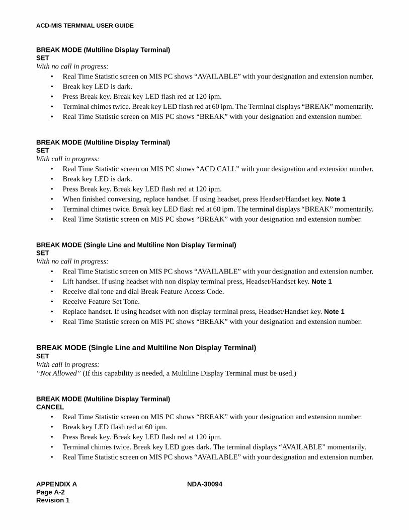
ACD-MIS TERMNIAL USER GUIDE
BREAK MODE (Multiline Display Terminal)SETWith no call in progress:
• Real Time Statistic screen on MIS PC shows “AVAILABLE” with your designation and extension number.• Break key LED is dark.• Press Break key. Break key LED flash red at 120 ipm.• Terminal chimes twice. Break key LED flash red at 60 ipm. The Terminal displays “BREAK” momentarily.• Real Time Statistic screen on MIS PC shows “BREAK” with your designation and extension number.
BREAK MODE (Multiline Display Terminal)SETWith call in progress:
• Real Time Statistic screen on MIS PC shows “ACD CALL” with your designation and extension number.• Break key LED is dark.• Press Break key. Break key LED flash red at 120 ipm.• When finished conversing, replace handset. If using headset, press Headset/Handset key. Note 1
• Terminal chimes twice. Break key LED flash red at 60 ipm. The terminal displays “BREAK” momentarily.• Real Time Statistic screen on MIS PC shows “BREAK” with your designation and extension number.
BREAK MODE (Single Line and Multiline Non Display Terminal)SETWith no call in progress:
• Real Time Statistic screen on MIS PC shows “AVAILABLE” with your designation and extension number.• Lift handset. If using headset with non display terminal press, Headset/Handset key. Note 1
• Receive dial tone and dial Break Feature Access Code.• Receive Feature Set Tone.• Replace handset. If using headset with non display terminal press, Headset/Handset key. Note 1
• Real Time Statistic screen on MIS PC shows “BREAK” with your designation and extension number.
BREAK MODE (Single Line and Multiline Non Display Terminal)SETWith call in progress:“Not Allowed” (If this capability is needed, a Multiline Display Terminal must be used.)
BREAK MODE (Multiline Display Terminal)CANCEL
• Real Time Statistic screen on MIS PC shows “BREAK” with your designation and extension number.• Break key LED flash red at 60 ipm.• Press Break key. Break key LED flash red at 120 ipm.• Terminal chimes twice. Break key LED goes dark. The terminal displays “AVAILABLE” momentarily.• Real Time Statistic screen on MIS PC shows “AVAILABLE” with your designation and extension number.
APPENDIX A NDA-30094Page A-2Revision 1

ACD-MIS TERMINAL USER GUIDE
BREAK MODE (Single Line and Multiline Non Display Terminal)CANCEL
• Real Time Statistic screen on MIS PC shows “BREAK” with your designation and extension number.• Lift handset. If using headset with non display terminal press, Headset/Handset key. Note 1
• Receive dial tone and dial Break Feature Access Code.• Receive Feature Set Tone.• Replace handset. If using headset with non display terminal press, Headset/Handset key. Note 1
• Real Time Statistic screen on MIS PC shows “AVAILABLE” with your designation and extension number.
WORK MODE (Multiline Display Terminal)SETWith no call in progress:
• Real Time Statistic screen on MIS PC shows “AVAILABLE” with your designation and extension number.• Work key LED is dark.• Press Work key. Work key LED flash red at 120 ipm.• Terminal chimes twice. Work key LED flash red at 60 ipm. The terminal displays “WORK” momentarily.• Real Time Statistic screen on MIS PC shows “WORK” with your designation and extension number.
WORK MODE (Multiline Display Terminal)SETWith call in progress:
• Real Time Statistic screen on MIS PC shows “ACD CALL” with your designation and extension number.• Work key LED is dark.• Press Work key. Work key LED flash red at 120 ipm.• When finished conversing replace handset (if using headset press Headset/Handset key) Note 1
• Terminal chimes twice. Work key LED flash red at 60 ipm. The terminal displays “WORK” momentarily.• Real Time Statistic screen on MIS PC shows “WORK” with your designation and extension number.
WORK MODE (Single Line and Multiline Non Display Terminal)SETWith no call in progress:
• Real Time Statistic screen on MIS PC shows “AVAILABLE” with your designation and extension number.• Lift handset. If using headset with non display terminal, press Headset/Handset key. Note 1
• Receive dial tone and dial Work Feature Access Code.• Receive Feature Set Tone.• Replace handset. If using headset with non display terminal, press Headset/Handset key. Note 1
• Real Time Statistic screen on MIS PC shows “WORK” with your designation and extension number.
NDA-30094 APPENDIX APage A-3
Revision 1
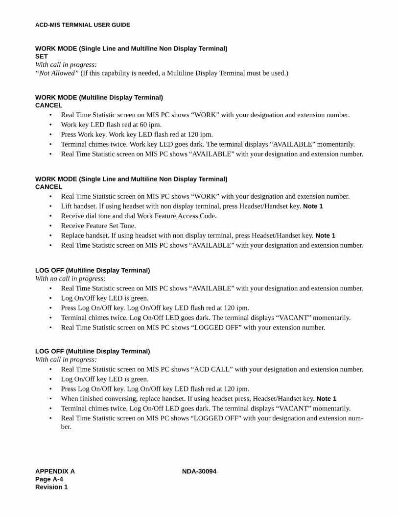
ACD-MIS TERMNIAL USER GUIDE
WORK MODE (Single Line and Multiline Non Display Terminal)SETWith call in progress:“Not Allowed” (If this capability is needed, a Multiline Display Terminal must be used.)
WORK MODE (Multiline Display Terminal)CANCEL
• Real Time Statistic screen on MIS PC shows “WORK” with your designation and extension number.• Work key LED flash red at 60 ipm.• Press Work key. Work key LED flash red at 120 ipm.• Terminal chimes twice. Work key LED goes dark. The terminal displays “AVAILABLE” momentarily.• Real Time Statistic screen on MIS PC shows “AVAILABLE” with your designation and extension number.
WORK MODE (Single Line and Multiline Non Display Terminal)CANCEL
• Real Time Statistic screen on MIS PC shows “WORK” with your designation and extension number.• Lift handset. If using headset with non display terminal, press Headset/Handset key. Note 1
• Receive dial tone and dial Work Feature Access Code.• Receive Feature Set Tone.• Replace handset. If using headset with non display terminal, press Headset/Handset key. Note 1
• Real Time Statistic screen on MIS PC shows “AVAILABLE” with your designation and extension number.
LOG OFF (Multiline Display Terminal)With no call in progress:
• Real Time Statistic screen on MIS PC shows “AVAILABLE” with your designation and extension number.• Log On/Off key LED is green.• Press Log On/Off key. Log On/Off key LED flash red at 120 ipm.• Terminal chimes twice. Log On/Off LED goes dark. The terminal displays “VACANT” momentarily.• Real Time Statistic screen on MIS PC shows “LOGGED OFF” with your extension number.
LOG OFF (Multiline Display Terminal)With call in progress:
• Real Time Statistic screen on MIS PC shows “ACD CALL” with your designation and extension number.• Log On/Off key LED is green.• Press Log On/Off key. Log On/Off key LED flash red at 120 ipm.• When finished conversing, replace handset. If using headset press, Headset/Handset key. Note 1
• Terminal chimes twice. Log On/Off LED goes dark. The terminal displays “VACANT” momentarily.• Real Time Statistic screen on MIS PC shows “LOGGED OFF” with your designation and extension num-
ber.
APPENDIX A NDA-30094Page A-4Revision 1
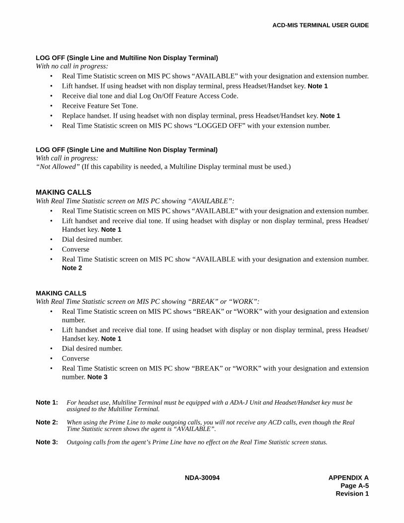
ACD-MIS TERMINAL USER GUIDE
LOG OFF (Single Line and Multiline Non Display Terminal)With no call in progress:
• Real Time Statistic screen on MIS PC shows “AVAILABLE” with your designation and extension number.• Lift handset. If using headset with non display terminal, press Headset/Handset key. Note 1
• Receive dial tone and dial Log On/Off Feature Access Code.• Receive Feature Set Tone.• Replace handset. If using headset with non display terminal, press Headset/Handset key. Note 1
• Real Time Statistic screen on MIS PC shows “LOGGED OFF” with your extension number.
LOG OFF (Single Line and Multiline Non Display Terminal)With call in progress:“Not Allowed” (If this capability is needed, a Multiline Display terminal must be used.)
MAKING CALLSWith Real Time Statistic screen on MIS PC showing “AVAILABLE”:
• Real Time Statistic screen on MIS PC shows “AVAILABLE” with your designation and extension number.• Lift handset and receive dial tone. If using headset with display or non display terminal, press Headset/
Handset key. Note 1
• Dial desired number.• Converse• Real Time Statistic screen on MIS PC show “AVAILABLE with your designation and extension number.
Note 2
MAKING CALLSWith Real Time Statistic screen on MIS PC showing “BREAK” or “WORK”:
• Real Time Statistic screen on MIS PC shows “BREAK” or “WORK” with your designation and extensionnumber.
• Lift handset and receive dial tone. If using headset with display or non display terminal, press Headset/Handset key. Note 1
• Dial desired number.• Converse• Real Time Statistic screen on MIS PC show “BREAK” or “WORK” with your designation and extension
number. Note 3
Note 1: For headset use, Multiline Terminal must be equipped with a ADA-J Unit and Headset/Handset key must be assigned to the Multiline Terminal.
Note 2: When using the Prime Line to make outgoing calls, you will not receive any ACD calls, even though the Real Time Statistic screen shows the agent is “AVAILABLE”.
Note 3: Outgoing calls from the agent’s Prime Line have no effect on the Real Time Statistic screen status.
NDA-30094 APPENDIX APage A-5
Revision 1

ACD-MIS TERMNIAL USER GUIDE
APPENDIX A NDA-30094Page A-6Revision 1
Related Documents