NASA Technical NASA-TP-2511 19850025835 Paper 2511 August 1985 Space Station Rotational Equations of Motion \ Mario H. Rheinfurth and Stanley N. Carroll .... 7 ' • .. :, i • N/A https://ntrs.nasa.gov/search.jsp?R=19850025835 2018-05-04T13:07:00+00:00Z

Welcome message from author
This document is posted to help you gain knowledge. Please leave a comment to let me know what you think about it! Share it to your friends and learn new things together.
Transcript
NASATechnical NASA-TP-2511 19850025835
Paper2511
August 1985
Space Station RotationalEquations of Motion
\
Mario H. Rheinfurth
and Stanley N. Carroll
.... 7 '
• .. :,i •
N/A
https://ntrs.nasa.gov/search.jsp?R=19850025835 2018-05-04T13:07:00+00:00Z

3 1176 01316 2830 !
NASATechnicalPaper2511
1985
Space Station RotationalEquations of Motion
Mario H. Rheinfurth
and Stanley N. Carroll
George C. Marshall Space Flight CenterMarshall Space Flight Center, Alabama
RII SANational Aeronauticsand Space Administratiof
Scientific and TechnicaInformation Branch

TABLE OF CONTENTS
Page
I. INTRODUCTION ......................................................... ... 1
II. DERIVATION OF ROTATIONAL EQUATIONS OF MOTION ....................... 1
A. Method 1: D'Alembert's Principle ........................................... 1B. Method 2: Angular Momentum Principle ................. _ ................... 6
III. VECTOR-DYADIC TO MATRIX TRANSFORMATION ............................. 8
IV. APPENDAGE ORIENTATION KINEMATICS ..................................... 9
V. CONCLUSIONS ............................................................ 11
APPENDIX A .................................................................... 13
APPENDIX B .................................................................... 15
LIST OF ILLUSTRATIONS
Figure Title Page
21. Space Station (Power Tower configuration) ........................ - ............
2. Inertial and moving reference frames .......................................... 2
.°°111
DEFINITION OF SYMBOLS
Symbol Definition
a relative acceleration of a mass element as observed in moving reference frame.
Ap coordinate transformation from the main body system to the appendage system.
Cp* specially defined Coriolis matrix. Format is shown in body of report.
dm element of mass.
_Hp angular momentum of rotating appendage about its mass center.
_Hv angular momentum of vehicle, including non-rotating appendages.
HT angular momentum of the total system about its mass center.
I inertia matrix for the total system, a time varying quantity.
Ip inertia matrix for appendage
1o position vector of appendage mass center relative to the composite mass center.
lp position vector of appendage mass element relative to the appendage mass center.
L_ vector sum of all external torques about the composite mass center.
r position vector of mass element relative to composite mass center.
rp position vector of appendage mass element relative to composite mass center.
i_ absolute acceleration of mass element.
_o absolute acceleration of the origin of the moving reference frame.
v relative velocity of mass element observed in the moving reference frame.
ot rotation angle of appendage based on orbital position.
/3 rotation angle of appendage based on sun position.
_2 angular velocity vector of moving reference frame (main body) with respect to inertialspace.
_Wp angular velocity vector of appendage reference frame with respect to the moving referenceframe.
-_ = (_)1 angular acceleration of the main body relative to inertial space.
@p = (w_"p)v angular acceleration of an appendage relative to the main body.
iv
(8)I time rate of change of vector H relative to inertial space.
(H_")v time rate of change of vector H relative to the main body.
E unit dyadic.
I inertia dyadic for total system.
=/p inertia dyadic for appendage.
C Coriolis dyadic.

TECHNICAL PAPER
SPACESTATION ROTATIONAL EQUATIONS OF MOTION
I. INTRODUCTION
This report derives the rotational equations of motion for a large space structure having append-ages that can rotate relative to the main body. In particular, the equations were formulated for use inthe Space Station Attitude Control and Stabilization Test Bed. The solar arrays and thermal radiatorsof the Space Station are required to maintain a specific alignment with the sun, whereas the main bodyof the Space Station rotates at orbital rate in an Earth pointing attitude. Thus the angular velocity ofthe appendages relative to the Space Station is approximately opposite to the orbital rate.
Two methods are given for the derivation of the rotational equations of motion. The firstmethod uses D'Alembert's principle whereas the second method is based on the angular momentum con-cept. It is shown that the two formulations are dynamically equivalent although the resulting differentialequations are significantly different concerning their mathematical structure. It should be noted thatthroughout the report the terms appendage, solar arrays or panels and thermal radiator are usedinterchangeably.
II. DERIVATION OF ROTATIONAL EQUATIONS OF MOTION
A. Method 1: D'Alembert'sPrinciple
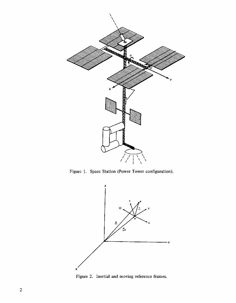
In this method, the rotational equations of motion are derived by applying D'Alembert's principle.The equations of motion are presented in a form suitable for attitude and stabilization studies of theSpace Station. Its Power Tower configuration is schematically shown in Figure 1. The rotational equa-tions will be written in terms of a moving reference frame, whose origin is located at the mass centerof the total system and which rotates with the main body. In Figure 2 the XYZ system is fixed ininertial space and the xyz system is the moving reference (body) frame which translates and rotatesrelative to it. Notice that this body frame is, in general, not fixed in the main body but has a transla-tional motion relative to it because of the change in location of the composite mass center relative to themain body due to internal moving components. However, the rotational rate of the body frame isidentical to that of the main body at all times.
Now, D'Alembert's principle states that the vector sum of the moments of all inertial and externalforces relative to _ point is zero. Taking moments about the composite mass center of the SpaceStation, the following vector equation is obtained:
+frx dm) = 0 (1)
The absolute acceleration _ of each mass particle dm can be expressed in terms of quantities measuredin the rotating reference frame by the well-known relation:
\\
\\\
Figure 1. Space Station (Power Tower configuration).
z p
Figure 2. Inertial and moving reference frames.
2
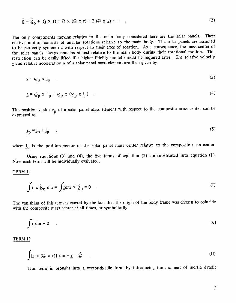
=_o + (_- xr)+__ x (gZ_x.r)+2(_ x v)+a (2)
The only components moving relative to the main body considered here are the solar panels. Theirrelative motion consists of angular rotations relative to the main body. The solar panels are assumedto be perfectly symmetric with respect to their axes of rotation. As a consequence, the mass center ofthe solar panels always remains at rest relative to the main body during their rotational motion. Thisrestriction can be easily lifted if a higher fidelity model should be required later. The relative velocityv and relative acceleration a of a solar panel mass element are then given by
v = Wp x jp (3)
a =Up x Ip +Up x (_Wp xlp) (4)
The position vector rp of a solar panel mass element with respect to the composite mass center can beexpressed as:
_rp=Jo +Jp , (5)
where 1o is the position vector of the solar panel mass center relative to the composite mass center.
Using equations (3) and (4), the five terms of equation (2) are substituted into equation (1).Now each term will be individually evaluated.
TERM I:
fr x _o dm = f_rdm x _o = 0 (I)
The vanishing of this term is caused by the fact that the origin of the body frame was chosen to coincidewith the composite mass center at all times, or symbolically
rdm = 0 (6)
TERM II:
f[r x(__ x 1")1dm=/ • _a (II)
This term is brought into a vector-dyadic form by introducing the moment of inertia dyadic
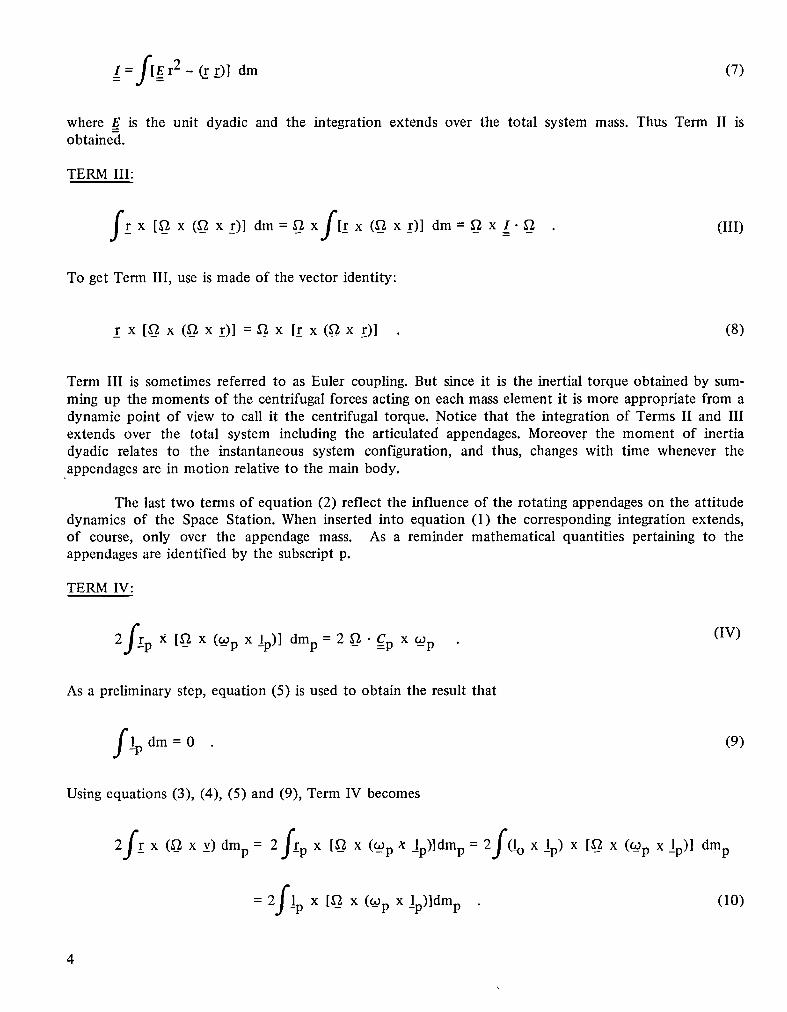
I= f[Er 2 - _.r__)]dm (7)
where _Eis the unit dyadic and the integration extends over the total system mass. Thus Term II isobtained.
TERM III:
r x [g X (__ x Z)] dm = __ xfirx(-xr,,dm = _ x I. _2 (III)
To get Term III, use is made of the vector identity:
r x[gx(gx_r)l =_x [_rx(__x_r)l (8)
Term III is sometimes referred to as Euler coupling. But since it is the inertial torque obtained by sum-ming up the moments of the centrifugal forces acting on each mass element it is more appropriate from adynamic point of view to call it the centrifugal torque. Notice that the integration of Terms II and IIIextends over the total system including the articulated appendages. Moreover the moment of inertiadyadic relates to the instantaneous system configuration, and thus, changes with time whenever theappendages are in motion relative to the main body.
The last two terms of equation (2) reflect the influence of the rotating appendages on the attitudedynamics of the Space Station. When inserted into equation (1) the corresponding integration extends,of course, only over the appendage mass. As a reminder mathematical quantities pertaining to theappendages are identified by the subscript p.
TERM IV:
2frp X [_ x (__p x l_p)] dmp = 2 _ • Cp x __p (IV)
As a preliminary step, equation (5) is used to obtain the result that
lp dm = 0 (9)
Using equations (3), (4), (5) and (9), Term IV becomes
2fr x (_ x v)dmp=2 f_rp x [__ x (W_pg lp)]dmp = 2f x lp)x [_ x (OA_pXlp)] dmp
= 2flp x [_ x (Wp x _lp)ldmp (10)
4
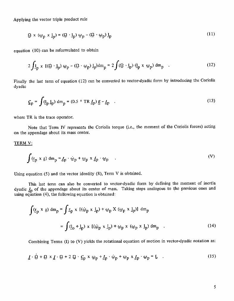
Applying the vector triple product rule
__ x (__px l_p)= (__•l_p)_p - (__•_p)Ip (II)
equation (10) can be reformulated to obtain
2f_lp x [(__ .lp) __p - (__ "__p) l_pldmp = 2f(__ .l_p) (l_px __p) dmp(12)
Finally the last term of equation (12) can be converted to vector-dyadic form by introducing the Coriolisdyadic
__Cp= f(l_p lp) dmp = (0.5 * TR=/p)__g-___/p(13)
where TR is the trace operator.
Note that Term IV represents the Coriolis torque (i.e., the moment of the Coriolis forces) actingon the appendage about its mass center.
TERM V:
rp x _a)dmp =gp" Up + __p x =/p• __p (V)
Using equation (5) and the vector identity (8), Term V is obtained.
This last term can also be converted to vector-dyadic form by defining the moment of inertia
dyadic __/pof the appendage about its center of mass. Taking steps analogous to the previous ones andusing eqt_ation (4), the following equation is obtained:
f(_r x a) dmp = f_ px [(Up x lp) + __px (Up x lp)] dmpp - _
= f(l_o + lp) x [(__p x !p) + Up x (_p x l_p)dmp (14)
Combining Terms (I) to (V) yields the rotational equation of motion in vector-dyadicnotation as:
/. _ + __ x_/. f_ + 2 0" __Cpx _p+/p • _d)p+ __p x/p • __p = _L (15)
5
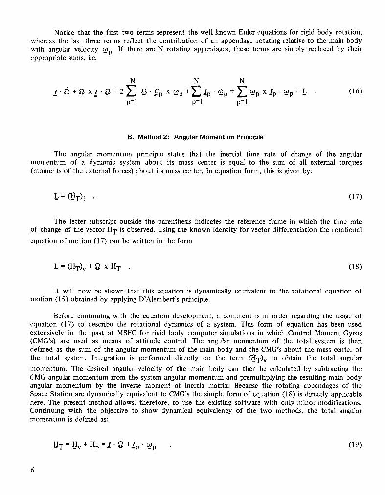
Notice that the first two terms represent the well known Euler equations for rigid body rotation,whereas the last three terms reflect the contribution of an appendage rotating relative to the main body
with angular velocity __p. If there are N rotating appendages, these terms are simply replaced by theirappropriate sums, i.e.
N N N
=/- __+__ x__/-_+2Z _'Cp x &p+E=/p.@p +ZUp X/p'__p = L (16)p=l p=l p=l
B. Method2: AngularMomentumPrinciple
The angular momentum principle states that the inertial time rate of change of the angularmomentum of a dynamic system about its mass center is equal to the sum of all external torques(moments of the external forces) about its mass center. In equation form, this is given by:
_L= (H'T) I (17)
The letter subscript outside the parenthesis indicates the reference frame in which the time rateof change of the vector HT is observed. Using the known identity for vector differentiation the rotationalequation of motion (17) can be written in the form
_L= (liT) v + __ x HT (18)
It will now be shown that this equation is dynamically equivalent to the rotational equation ofmotion (15) obtained by applying D'Alembert's principle.
Before continuing with the equation development, a comment is in order regarding the usage ofequation (17) to describe the rotational dynamics of a system. This form of equation has been usedextensively in the past at MSFC for rigid body computer simulations in which Control Moment Gyros(CMG's) are used as means of attitude control. The angular momentum of the total system is thendefined as the sum of the angular momentum of the main body and the CMG's about the mass center ofthe total system. Integration is performed directly on the term (_T)v to obtain the total angularmomentum. The desired angular velocity of the main body can then be calculated by subtracting theCMG angular momentum from the system angular momentum and premultiplying the resulting main bodyangular momentum by the inverse moment of inertia matrix. Because the rotating appendages of theSpace Station are dynamically equivalent to CMG's the simple form of equation (18) is directly applicablehere. The present method allows, therefore, to use the existing software with only minor modifications.Continuing with the objective to show dynamical equivalency of the two methods, the total angularmomentum is defined as:
_HT = _Hv + _Hp=_/- _2 +/p • _Wp (19)
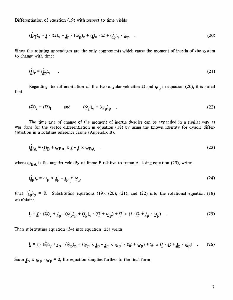
Differentiation of equation (19) with respect to time yields
(H-"T)v =/" (_)v +=/p " (-°Sp)v +/(_)_"v " _- + (_)p)v "-_p (20)
Since the rotating appendages are the only components which cause the moment of inertia of the systemto change with time:
(i)v== Qp)v (21)
Regardingthe differentiation of the two angular velocities__and Up in equation (20), it is notedthat
(-_)v = (O)I and (-_p)v = (_p)p (22)
The time rate of change of the moment of inertia dyadics can be expanded in a similar way aswas done for the vector differentiation in equation (18) by using the known identity for dyadic differ-entiation in a rotating reference frame (Appendix B).
_)A = (i)B + UBA x I - I x UBA (23)
where -_BA is the angular velocity of frame B relative to frame A. Using equation (23), write:
(_p)v = Up x/p -__/px __p (24)
since C_/p)p= O. Substitutingequations(19), (20), (21), and (22) into the rotational equation (18)weobtain:
L ==/. (_)v +=/p" (_p)p + (=ip)v" (6 + _Wp)+ _ x _. _ +=/p- Up) (25)
Then substituting equation (24) into equation (25) yields
L = =/. ('gl)v +=/p • (_p)p + (Up x/p -/p x _p) • (g + _OOp)+ _ x (=/- _ +=/p • Up) (26)
Since/p x _Wp• Up = O, the equation simplies further to the final form:
_L=/- (-_)v+lp" (&p)P +_- xI._+_pX__/p. COp+ [&p X=/p'__ -_p x COp)'__
+ _ x/p • Up] (27)
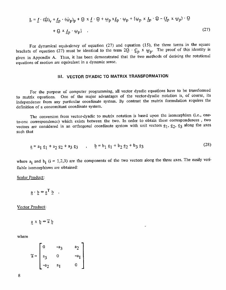
For dynamical equivalency of equation (27) and equation (15), the three terms in the square
brackets of equation (27) must be identical to the term 2__ • __Cpx _C2p.The proof of this identity isgiven in Appendix A. Thus, it has been demonstrated that the two methods of deriving the rotationalequations of motion are equivalent in a dynamic sense.
III. VECTOR DYADIC TO MATRIX TRANSFORMATION
For the purpose of computer programming, all vector dyadic equations have to be transformedto matrix equations. One of the major advantages of the vector-dyadic notation is, of course, itsindependence from any particular coordinate system. By contrast the matrix formulation requires thedefinition of a concomitant coordinate system.
The conversion from vector-dyadic to matrix notation is based upon the isomorphism (i.e., one-to-one correspondence) which exists between the two. In order to obtain these correspondences , twovectors are considered in an orthogonal coordinate system with unit vectors _el, e2, -e3 along the axessuch that
a =a 1-el +a2e2 +a3e3 , b =b 1 e1 +b 2e 2+b 3e 3 (28)
where ai and bi (i = 1,2,3) are the components of the two vectors along the three axes. The easily veri-fiable isomorphisms are obtained:
Scalar Product:
a.b_aTbm
Vector Product:
a x b #_b
where
3"= a3 0 -a 1
-a 2 a1 0
8
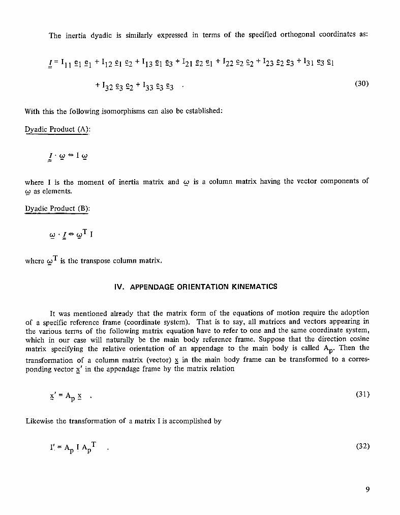
The inertia dyadic is similarly expressed in terms of the specified orthogonal coordinates as:
__/=Ill el e 1 +112el e2+113el e3+121e2e 1 +122e2e 2+123e2e 3+131e3e 1
+I32e 3e 2+133e 3e 3 (30)
With this the following isomorphisms can also be established:
Dyadic Product (A):
I._o*_Iw
where I is the moment of inertia matrix and _ is a column matrix having the vector components of_o as elements.m
Dyadic Product (B):
. l_.wT I
where w T is the transpose column matrix.
IV. APPENDAGEORIENTATION KINEMATICS
It was mentioned already that the matrix form of the equations of motion require the adoptionof a specific reference frame (coordinate system). That is to say, all matrices and vectors appearing inthe various terms of the following matrix equation have to refer to one and the same coordinate system,which in our case will naturally be the main body reference frame. Suppose that the direction cosine
matrix specifying the relative orientation of an appendage to the main body is called Ap. Then thetransformation of a column matrix (vector) x in the main body frame can be transformed to a corres-ponding vector x' in the appendage frame by the matrix relation
x' = Ap x (31)
Likewise the transformation of a matrix I is accomplished by
I' = Ap I Ap T (32)
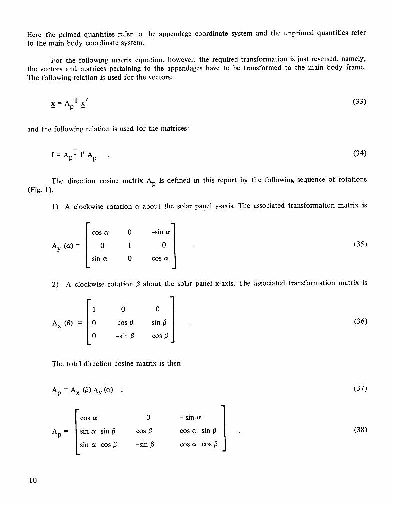
Here the primed quantities refer to the appendage coordinate system and the unprimed quantities referto the main body coordinate system.
For the following matrix equation, however, the required transformation is just reversed, namely,the vectors and matrices pertaining to the appendages have to be transformed to the main body frame.The following relation is used for the vectors:
_ = x' (33)x ApT
and the following relation is used for the matrices:
= I' Ap (34)I Ap T
The direction cosine matrix Ap is defined in this report by the following sequence of rotations(Fig. 1).
1) A clockwise rotation a about the solar panel y-axis. The associated transformation matrix is
cos a 0 -Sioa 1
Ay (or)= 0 1 (35)
sin ot 0 cos a j
2) A clockwise rotation /3 about the solar panel x-axis. The associated transformation matrix is
[ 001Ax (/3) = 0 cos/3 sin/3 (36)
0 -sin/3 cos/3
The total direction cosine matrix is then
Ap = Ax (/3)Ay (a) (37)
cos a 0 - sin o_ 1Ap = /sin a sin/3 cos 13 cos a sin/3 (38)
LSin o_ cos/3 -sin/3 cos _ cos/3
10
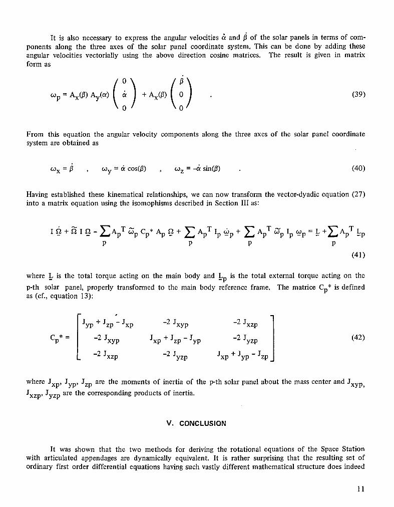
It is also necessary to express the angular velocities & and _ of the solar panels in terms of com-ponents along the three axes of the solar panel coordinate system. This can be done by adding theseangular velocities vectorially using the above direction cosine matrices. The result is given in matrixform as
(°/cop = Ax(0) Ay(O0 & + Ax(0) 0 (39)0 0
From this equation the angular velocity components along the three axes of the solar panel coordinatesystem are obtained as
cox = _ , COy= d cos(0) , COz= "& sin(0) (40)
Having established these kinematical relationships, we can now transform the vector-dyadic equation (27)into a matrix equation using the isomophisms described in Section III as:
where _Lis the total torque acting on the main body and _Lpis the total external torque acting on the
p-th solar panel, properly transformed to the main body reference frame. The matrice Cp* is definedas (cf., equation 13):
I 1Jyp + Jzp - Jxp -2 Jxyp -2 Jxzp
Cp* = -2 Jxyp Jxp + Jzp - Jyp -2 Jyzp (42)
-2 Jxzp -2 Jyzp Jxp + Jyp - Jzp
where Jxp, Jyp, Jzp are the moments of inertia of the p-th solar panel about the mass center and Jxyp,
Jxzp, Jyzp are the corresponding products of inertia.
V. CONCLUSION
It was shown that the two methods for deriving the rotational equations of the Space Stationwith articulated appendages are dynamically equivalent. It is rather surprising that the resulting set ofordinary first order differential equations having such vastly different mathematical structure does indeed
11
accurately represent the very same dynamical system. The equations based upon the angular momentummethod are quite simple in structure and many existing rigid body computer programs can easily bemodified to include the rotating appendages. On the other hand, the equations based upon D'Alembert'sprinciple provide more insight into the dynamic origin of their individual terms, which can be of con-siderable benefit in trying to understand the dynamic behavior of the system. Moreover, further refine-ments such as mass center offset of the rotating appendages and their flexibility require only additionalterms and no major restructuring of these equations. Ultimately, however, the choice of selecting theproper set of dynamic equations is largely a matter of personal predilection and experience with existingcomputer codes.
12
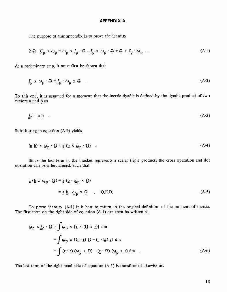
APPENDIX A
The purpose of this appendix is to prove the identity
2__ "Cp x Up=Up X=/p. __-__!p x Up" __+__ X=/p._Wp (A-l)
As a preliminary step, it must first be shown that
/p x Up " __ ==/p" Up x __ (A-2)
To this end, it is assumed for a moment that the inertia dyadic is defined by the dyadic product of twovectors a and b as
/p = a b (A-3)
Substituting in equation (A-2) yields
(_b) x Up'_=a(b_ x Up'_) (A-4)
Since the last term in the bracket represents a scalar triple product, the cross operation and dotoperation can be interchanged, such that
a(b x Up'_) =a(b'Up x __)
= a b__-Up x _ Q.E.D. (A-5)
To prove identity (A-l) it is best to return to the original definition of the moment of inertia.The first term on the right side of equation (A-l) can then be written as
Up X/p.__ =fUp x [rx (__ xr)] dm
f__p x [(r .r) __ - (r. __) r]dm
= f(r- r) (Up x __) - (r. __) (Up x r) dm (A-6)
The last term of the right hand side of equation (A-l) is transformed likewise as:
13
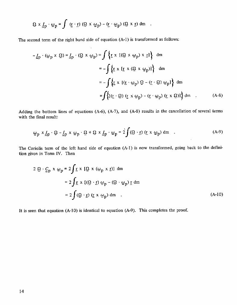
x/p • _p = f (r -r) (__X __p)- (r. COp)(_ x r) dm
The second term of the right hand side of equation (A-l) is transformed as follows:
-,p._ x_,)=__,p._,__p)=f{_xE_-___Wp)Xr]} dm
=-f{rx [r x(__ x _p)]} dm
=-f{_xt_._p).-,:_._.)_p]} dm
dm (A-8)
Adding the bottom lines of equations (A-6), (A-7), and (A-8) results in the cancellation of several termswith the final result:
_p x !p. _ -__/p x _p- __ + __ x/p • __p = _f(. r)(rx _Wp) dm (A-9)
The Coriolis term of the left hand side of equation (A-l) is now transformed, going back to the defini-tion given in Term IV. Then
2_.__Cp x Wp=2fr x [__ x (Wp xr)] dm
= 2fr x [(__ .r) _Wp- (__ • _Wp)r dm
=2f(_a._r)¢x__p)dm (A-10)
It is seen that equation (A-10) is identical to equation (A-9). This completes the proof.
14
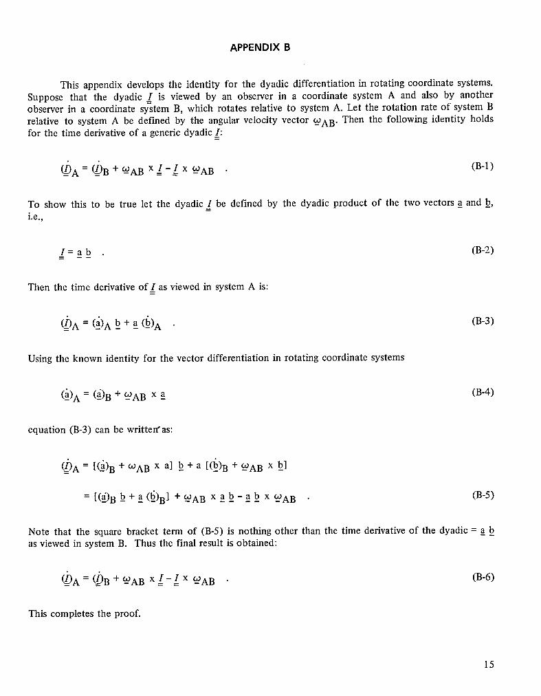
APPENDIX B
This appendix develops the identity for the dyadic differentiation in rotating coordinate systems.Suppose that the dyadic _/ is viewed by an observer in a coordinate system A and also by anotherobserver in a coordinate system B, which rotates relative to system A. Let the rotation rate of system Brelative to system A be defined by the angular velocity vector -_AB" Then the following identity holdsfor the time derivative of a generic dyadic I:
-(-_A= _(-_(-_B+ _-AB x I- I x -_AB (B-l)
To show this to be true let the dyadic_/be defined by the dyadic product of the two vectors a and b,i.e.,
I = a b (B-2)
Then the time derivative of I as viewed in system A is:
(_-I)A= (-a)Ab + a (_)A (B-3)
Using the known identity for the vector differentiation in rotating coordinate systems
('-a)A = (-a)B + -°JAB x a (B-4)
equation (B-3) can be written'as:
(hA = [_)B + ¢OABx al b + a [(l_)B + _AB x bl
= [(a_')Bb+a(b_') B] +_AB x ab-ab x _WAB (B-5)
Note that the square bracket term of (B-5) is nothing other than the time derivative of the dyadic = a bas viewed in system B. Thus the final result is obtained:
(=__A= _B + -WAB x I - I x WAB (B-6)
This completes the proof.
15


TECHNICAl_. REP_)..RT STANDARD TITLE PAGE1. REPORT NO. 2. GOVERNMENT"ACCESSION NO. 3. RECIPIENT'S CATALOG NO.NASA TP - 2511
'4. TITLE AND SUBTITLE 5. REPORT DATE
August 1985Space Station Rotational Equations of Motion 6. PERFORMINGORGANIZATIONCODE
7. AUTHOR(S) 8. PERFORMING'ORGANIZATIONREPORI"
Mario H. Rheinfurth and Stanley N. Carroll9. PERFORMING ORGANIZATION NAME AND ADDRESS 10. WORK UNIT NO.
M-497George C. Marshall Space Flight Center 11. CONTRACTORGRANTNO.Marshall Space Flight Center, Alabama 35812
13. TYPE OF REPORT & PERIOD COVERED
12. SPONSORING AGENCY NAME AND ADDRESS
National Aeronautics and Space Administration Technical PaperWashington, D.C. 20546 14. SPONSORINGAGENCYCODE
15. SUPPLEMENTARY NOTES
Prepared by Systems Dynamics Laboratory, Science and Engineering Directorate.
16. ABSTRACT
Dynamic equations of motion are developed which describe the rotational motion for a largespace structure having rotating appendages. The presence of the appendages produce torque couplingterms which are dependent on the inertia properties of the appendages and the rotational rates forboth the space structure and the appendages. These equations were formulated to incorporate intothe Space Station Attitude Control and Stabilization Test Bed to accurately describe the influencerotating solar arrays and thermal radiators have on the dynamic behavior of the Space Station.
17. KE_' WORDS IS. DISTRIBUTION sTATEMENT
Dynamics Unclassified - UnlimitedControl
Rotating appendagesD'alemberts principleAngular momentum
Subject Category 15
19. SECURITY CLASSlF.(otthlermpert_ 20. SECURITY CLASSIF. (otthl= I_iCe) 21. NO. OF PAGES 22. PRICE
Unclassified Unclassified 20 A02
MSFC - Form 3292 (May 1969)
For tale by National Technical Information Service, Springfield, Virginia 22161
NASA-Langley, 1985

.r .. .
NatiOnalAbronauticsand _SpaceAdministration I .....
IWashington,D.C,
20546 : 3 1176 01316 2830Official Business _---_ .....
Penalty for Private Use, $300
POSTMASTER: If Undeliverable (Section 1$8Postal Manual) Do Not Return
DONOTREMOVESLIPFROMMATERIAL i
Deleteyournamefromthisslipwhenreturningmaterial• tothelibrary. ,
NAME MS i
NASA Langley (Rev.May 1988) RIAD N-75
Related Documents