Welcome message from author
This document is posted to help you gain knowledge. Please leave a comment to let me know what you think about it! Share it to your friends and learn new things together.
Transcript
MXcatCOVandback.QXD 11/10/02 11:51 pm Page 1
Page 1
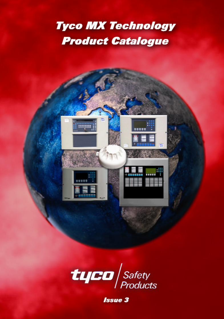
Features:
. MX VIRTUAL multi-sensor detectors
. MX DIGITAL robust & reliable high speed loop protocol
. Rapid response to fire conditions and very low false alarms through:. MX FASTLOGIC detection algorithms. MX HPO detection algorithms. MX CCO fire detection
Introduction
Tyco MX Technology brings together the latest firedetection technology from around the world into acomprehensive international range of fire detectionsystems. Tyco MX Technology can be used toprovide cost effective solutions on small fire detectionsystems whilst also providing the features andfunctions required on very large commercial andindustrial sites.
Tyco MX Technology is being made available on awide range of internationally approved panels andsystems available from Tyco companies world-wideincluding:
. MINERVA MX PANELS
. MINERVA MARINE T2000 PANELS
. ZETTLER EXPERT PANELS
. MINERVA SOLO PANELS
23SeptMXCat. qxd 11/10/02 11:42 pm Page 1
Table of Contents3 MX Panels
10 MX Panel Components
15 MX Panel User Interface Modules
19 MX Graph/ MX Net
21 Minerva Solo Detection Panels
22 Batteries
23 MX Virtual Multi-Sensor Detectors
26 Detector Mode Selection & Design Charts
28 Standard Universal Bases
29 Functional Detector Bases
30 Detector Ancillaries
34 Detector Housings
35 MX Ancillary
38 MX Addressable Input/Output Modules
42 MX Ancillary Housing
44 Programming & Service
Tools
45 Sales Tools
46 Approvals
47 Standard Auto CAD Symbols
48 Product Code Index
tycotycoPage 2
23SeptMXCat. qxd 11/10/02 11:42 pm Page 2
MX Detection Panels
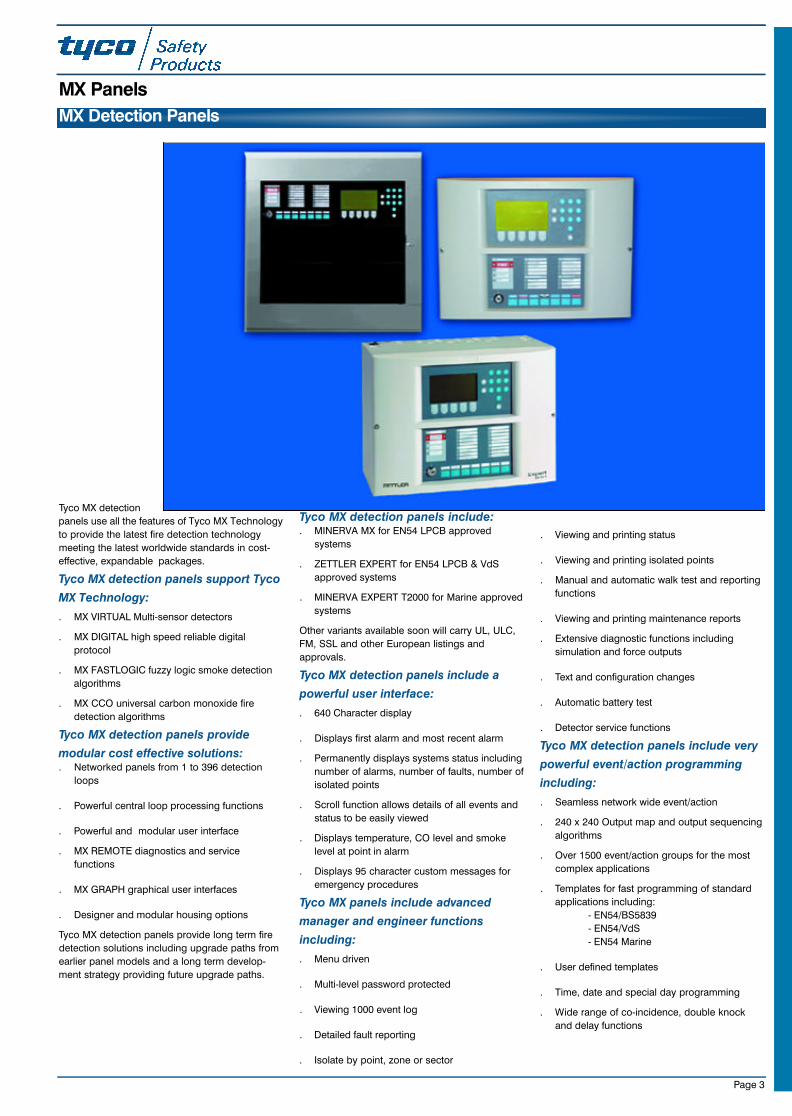
Tyco MX detection
panels use all the features of Tyco MX Technology
to provide the latest fire detection technology
meeting the latest worldwide standards in cost-
effective, expandable packages.
Tyco MX detection panels support Tyco
MX Technology:
. MX VIRTUAL Multi-sensor detectors
. MX DIGITAL high speed reliable digital
protocol
. MX FASTLOGIC fuzzy logic smoke detection
algorithms
. MX CCO universal carbon monoxide fire
detection algorithms
Tyco MX detection panels provide
modular cost effective solutions:. Networked panels from 1 to 396 detection
loops
. Powerful central loop processing functions
. Powerful and modular user interface
. MX REMOTE diagnostics and service
functions
. MX GRAPH graphical user interfaces
. Designer and modular housing options
Tyco MX detection panels provide long term fire
detection solutions including upgrade paths from
earlier panel models and a long term develop-
ment strategy providing future upgrade paths.
Tyco MX detection panels include:. MINERVA MX for EN54 LPCB approved
systems
. ZETTLER EXPERT for EN54 LPCB & VdS
approved systems
. MINERVA EXPERT T2000 for Marine approved
systems
Other variants available soon will carry UL, ULC,
FM, SSL and other European listings and
approvals.
Tyco MX detection panels include a
powerful user interface:
. 640 Character display
. Displays first alarm and most recent alarm
. Permanently displays systems status including
number of alarms, number of faults, number of
isolated points
. Scroll function allows details of all events and
status to be easily viewed
. Displays temperature, CO level and smoke
level at point in alarm
. Displays 95 character custom messages for
emergency procedures
Tyco MX panels include advanced
manager and engineer functions
including:
. Menu driven
. Multi-level password protected
. Viewing 1000 event log
. Detailed fault reporting
. Isolate by point, zone or sector
. Viewing and printing status
. Viewing and printing isolated points
. Manual and automatic walk test and reporting
functions
. Viewing and printing maintenance reports
. Extensive diagnostic functions including
simulation and force outputs
. Text and configuration changes
. Automatic battery test
. Detector service functions
Tyco MX detection panels include very
powerful event/action programming
including:
. Seamless network wide event/action
. 240 x 240 Output map and output sequencing
algorithms
. Over 1500 event/action groups for the most
complex applications
. Templates for fast programming of standard
applications including:
- EN54/BS5839
- EN54/VdS
- EN54 Marine
. User defined templates
. Time, date and special day programming
. Wide range of co-incidence, double knock
and delay functions
Page 3
MX Panels
23SeptMXCat. qxd 11/10/02 11:42 pm Page 3
Page 4
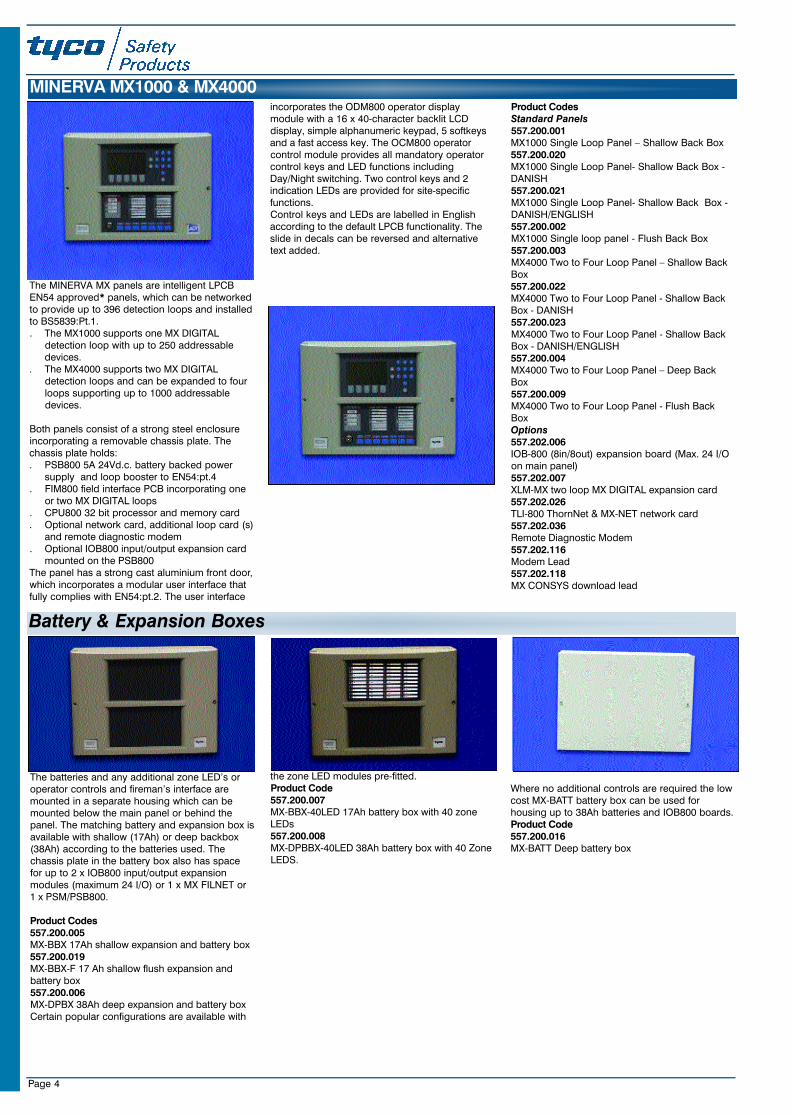
The MINERVA MX panels are intelligent LPCBEN54 approved* panels, which can be networkedto provide up to 396 detection loops and installedto BS5839:Pt.1. . The MX1000 supports one MX DIGITAL
detection loop with up to 250 addressabledevices.
. The MX4000 supports two MX DIGITALdetection loops and can be expanded to fourloops supporting up to 1000 addressabledevices.
Both panels consist of a strong steel enclosureincorporating a removable chassis plate. Thechassis plate holds:. PSB800 5A 24Vd.c. battery backed power
supply and loop booster to EN54:pt.4. FIM800 field interface PCB incorporating one
or two MX DIGITAL loops. CPU800 32 bit processor and memory card. Optional network card, additional loop card (s)
and remote diagnostic modem. Optional IOB800 input/output expansion card
mounted on the PSB800The panel has a strong cast aluminium front door,which incorporates a modular user interface thatfully complies with EN54:pt.2. The user interface
incorporates the ODM800 operator displaymodule with a 16 x 40-character backlit LCDdisplay, simple alphanumeric keypad, 5 softkeysand a fast access key. The OCM800 operatorcontrol module provides all mandatory operatorcontrol keys and LED functions includingDay/Night switching. Two control keys and 2indication LEDs are provided for site-specificfunctions.Control keys and LEDs are labelled in Englishaccording to the default LPCB functionality. Theslide in decals can be reversed and alternativetext added.
Product CodesStandard Panels557.200.001MX1000 Single Loop Panel – Shallow Back Box557.200.020MX1000 Single Loop Panel- Shallow Back Box -DANISH557.200.021MX1000 Single Loop Panel- Shallow Back Box -DANISH/ENGLISH557.200.002MX1000 Single loop panel - Flush Back Box557.200.003MX4000 Two to Four Loop Panel – Shallow BackBox557.200.022MX4000 Two to Four Loop Panel - Shallow BackBox - DANISH557.200.023MX4000 Two to Four Loop Panel - Shallow BackBox - DANISH/ENGLISH557.200.004MX4000 Two to Four Loop Panel – Deep BackBox557.200.009MX4000 Two to Four Loop Panel - Flush BackBoxOptions557.202.006IOB-800 (8in/8out) expansion board (Max. 24 I/Oon main panel)557.202.007XLM-MX two loop MX DIGITAL expansion card557.202.026TLI-800 ThornNet & MX-NET network card557.202.036Remote Diagnostic Modem557.202.116Modem Lead557.202.118MX CONSYS download lead
MINERVA MX1000 & MX4000
Battery & Expansion Boxes
The batteries and any additional zone LED’s oroperator controls and fireman’s interface aremounted in a separate housing which can bemounted below the main panel or behind thepanel. The matching battery and expansion box isavailable with shallow (17Ah) or deep backbox(38Ah) according to the batteries used. Thechassis plate in the battery box also has spacefor up to 2 x IOB800 input/output expansionmodules (maximum 24 I/O) or 1 x MX FILNET or1 x PSM/PSB800.
Product Codes557.200.005MX-BBX 17Ah shallow expansion and battery box557.200.019MX-BBX-F 17 Ah shallow flush expansion andbattery box557.200.006MX-DPBX 38Ah deep expansion and battery boxCertain popular configurations are available with
the zone LED modules pre-fitted.Product Code557.200.007MX-BBX-40LED 17Ah battery box with 40 zoneLEDs557.200.008MX-DPBBX-40LED 38Ah battery box with 40 ZoneLEDS.
Where no additional controls are required the lowcost MX-BATT battery box can be used forhousing up to 38Ah batteries and IOB800 boards.Product Code557.200.016MX-BATT Deep battery box
23SeptMXCat. qxd 11/10/02 11:42 pm Page 4
Page 5
The MINERVA MX full function repeater is an
EN54 LPCB approved repeater with optional
addressable EN54:Pt.4 power supply. The
repeater consists of a steel backbox and cast
aluminium front door which incorporates the
ODM800 operator display module with a 16 x 40-
character backlit LCD display, simple
alphanumeric keypad, 5 softkeys and a fast
access key. The OCM800 operator control
module provides all mandatory operator control
keys and LED functions including Day/Night
switching. Two control keys and 2 indication LEDs
are provided for site-specific functions.
Control keys and LEDs are labelled in English
according to the default LPCB functionality. The
slide in decals can be reversed and alternative
text added.
The back box has a removable chassis plate with
the PSM800 power supply, APM800 addressable
PSU monitor and space for 2 x 7 Ah batteries to
provide 72 h backup.
The MINERVA MX repeater with Power Supply is
connected to the Panel via the remote bus
(RS485, 1200 m distance). A maximum of 2
repeaters (including one MX REMOTE repeater)
can be linked to each MINERVA MX panel and
can provide full repeater functions for all panels
on the system.
The operator control module (OCM800) can
support up to 80 inputs and outputs in the form of
LED annunciators, IOB800 input/output modules,
XIOM universal I/O modules or XIOM 800 LED
mimic module.
Product Codes
Standard Repeaters
557.200.012
MXR Repeater with shallow backbox
557.200.017
MXR-F Repeater with flush backbox
557.200.013
MXR-PSU Repeater and addressable PSU
557.200.018
MXR-PSU-F Repeater and addressable PSU with
flush backbox
Options
557.202.006
IOB-800 (8in/8out) expansion board
557.180.005
Mimic driver module
557.180.016
XIOM universal I/O module
557.202.028
RSM800 PSU Module
557.202.042
24VDC Repeater Cable Assembly
MINERVA MX Repeaters
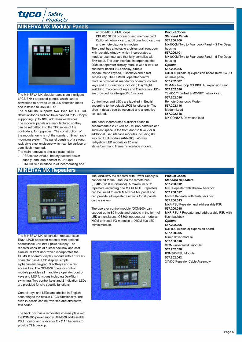
The MINERVA MX Modular panels are intelligent
LPCB EN54 approved panels, which can be
networked to provide up to 396 detection loops
and installed to BS5839:Pt.1.
The MX4000M supports two Tyco MX DIGITAL
detection loops and can be expanded to four loops
supporting up to 1000 addressable devices.
The modular panels are manufactured so they
can be retrofitted into the TFX series of fire
controllers, for upgrades. The construction of
the modular units is not the standard 19 inch rack
mounting system. The panel consists of a strong
rack style steel enclosure which can be surface or
semi-flush mounted.
The main removable chassis plate holds:
. PSB800 5A 24Vd.c. battery backed power
supply and loop booster to EN54pt4
. FIM800 field interface PCB incorporating one
or two MX DIGITAL loops
. CPU800 32 bit processor and memory card
. Optional network card, additional loop card (s)
and remote diagnostic modem
The panel has a lockable architectural front door
with lockable window, which incorporates a
modular user interface that fully complies with
EN54:pt.2. The user interface incorporates the
ODM800 operator display module with a 16 x 40-
character backlit LCD display, simple
alphanumeric keypad, 5 softkeys and a fast
access key. The OCM800 operator control
module provides all mandatory operator control
keys and LED functions including Day/Night
switching. Two control keys and 2 indication LEDs
are provided for site-specific functions.
Control keys and LEDs are labelled in English
according to the default LPCB functionality. The
slide in decals can be reversed and alternative
text added.
The panel incorporates sufficient space to
accommodate 2 x 17Ah or 2 x 38Ah batteries and
sufficient space in the front door to take 2 or 6
additional user interface modules including 80
way red LED module (ANN880) , 40 way
red/yellow LED module or 20 way
status/command fireman’s interface module.
Product Codes
Standard Panels
557.200.100
MX4000M Two to Four Loop Panel – 3 Tier Deep
housing
557.200.101
MX4000M Two to Four Loop Panel – 5 Tier Deep
housing
Options
557.202.006
IOB-800 (8in/8out) expansion board (Max. 24 I/O
on main panel)
557.202.007
XLM-MX two loop MX DIGITAL expansion card
557.202.026
TLI-800 ThornNet & MX-NET network card
557.202.036
Remote Diagnostic Modem
557.202.116
Modem Lead
557.202.118
MX CONSYS Download lead
MINERVA MX Modular Panels
23SeptMXCat. qxd 11/10/02 11:42 pm Page 5
Page 6
The T2000 full function repeater is an EN54Marine approved repeater with optionaladdressable EN54:Pt.4 power supply. Therepeater consists of a steel backbox and castaluminium front door which incorporates theODM800 operator display module with a 16 x 40-character backlit LCD display, simplealphanumeric keypad, 5 softkeys and a fastaccess key. The OCM800 operator controlmodule provides all mandatory operator controlkeys and LED functions including Day/Nightswitching. Two control keys and 2 indication LEDsare provided for vessel-specific functions.Control keys and LEDs are labelled in English
according to the default Marine functionality. Theslide in decals can be reversed and alternativetext added.The back box has a removable chassis plate withthe PSM800M power supply, APM800addressable PSU monitor and space for 2 x 7 Ahbatteries to provide 72 h backup.The T2000 repeater with Power Supply isconnected to the Panel via the remote bus(RS485, 1200 m distance). A maximum of x 2repeaters (including one MX REMOTE repeater)can be linked to each T2000 panel and canprovide full repeater functions for all panels onthe system. The operator control module (OCM800) cansupport up to 80 inputs and outputs in the form ofLED annunciators, IOB800 input/output modules,XIOM universal I/O modules or XIOM 800 LEDmimic module.
Product Codes557.200.601T2000R Marine Repeater with Power Supply Unit557.200.604T2000R Marine Repeater without Power SupplyUnit
MINERVA Expert T2000 Marine Repeater
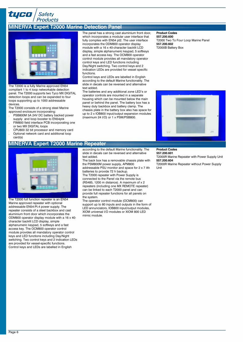
The T2000 is a fully Marine approved EN54compliant 1 to 4 loop networkable detectionpanel. The T2000 supports two Tyco MX DIGITALdetection loops and can be expanded to fourloops supporting up to 1000 addressabledevices.The T2000 consists of a strong steel Marineapproved enclosure incorporating:. PSB800M 5A 24V DC battery backed power
supply and loop booster to EN54pt4. FIM800 field interface PCB incorporating one
or two MX DIGITAL loops. CPU800 32 bit processor and memory card. Optional network card and additional loop
card(s)
The panel has a strong cast aluminium front door,which incorporates a modular user interface thatfully complies with EN54 pt2. The user interfaceincorporates the ODM800 operator displaymodule with a 16 x 40-character backlit LCDdisplay, simple alphanumeric keypad, 5 softkeysand a fast access key. The OCM800 operatorcontrol module provides all mandatory operatorcontrol keys and LED functions includingDay/Night switching. Two control keys and 2indication LEDs are provided for vessel specificfunctions.Control keys and LEDs are labelled in Englishaccording to the default Marine functionality. Theslide in decals can be reversed and alternativetext added.The batteries and any additional zone LED’s oroperator controls are mounted in a separatehousing which can be mounted below the mainpanel or behind the panel. The battery box has aheavy duty backbox and battery clamp. Thechassis plate in the battery box also has space forup to 2 x IOB800 input/output expansion modules(maximum 24 I/O) or 1 x PSM/PSB800.
Product Codes557.200.600T2000 Two To Four Loop Marine Panel557.200.602T2000B Battery Box
MINERVA Expert T2000 Marine Detection Panel
23SeptMXCat. qxd 11/10/02 11:42 pm Page 6
Page 7
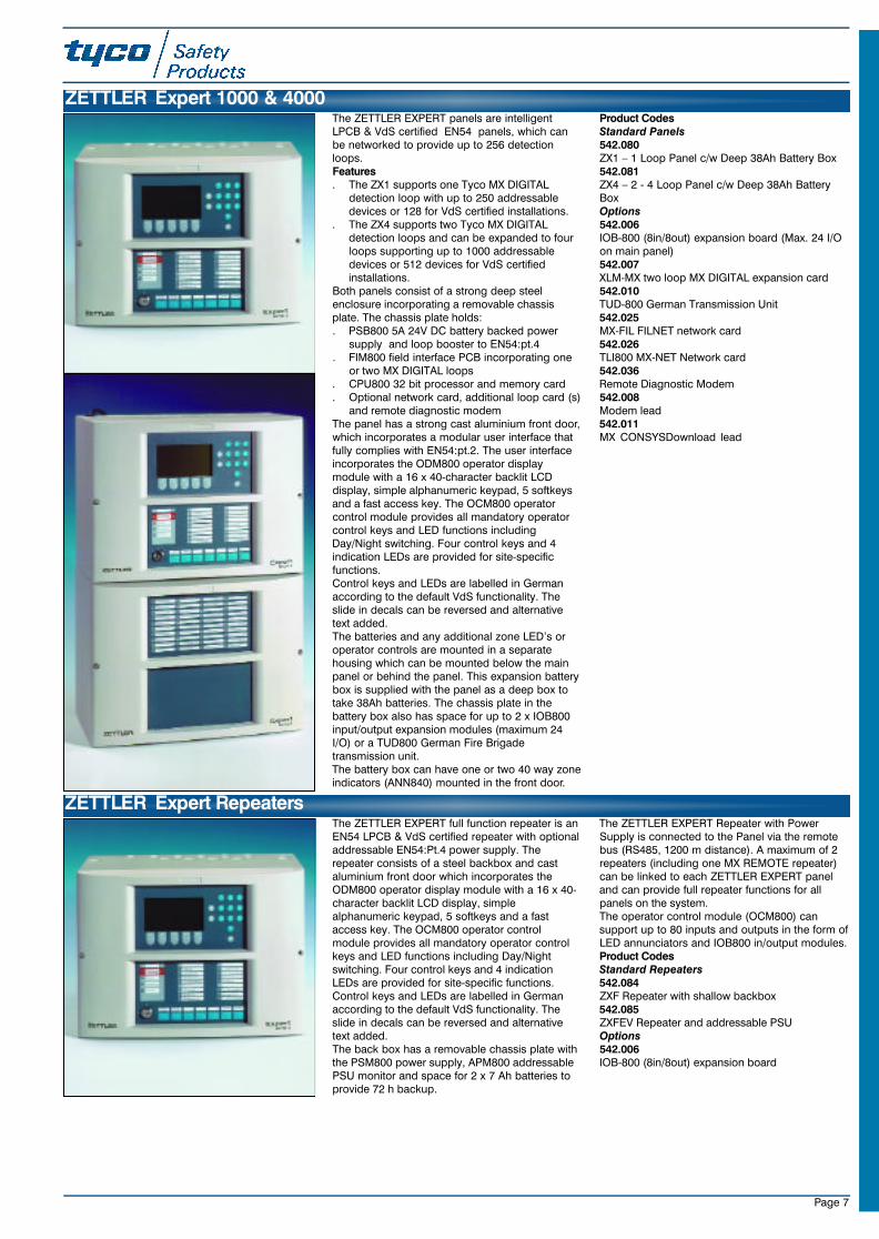
The ZETTLER EXPERT panels are intelligentLPCB & VdS certified EN54 panels, which canbe networked to provide up to 256 detectionloops. Features. The ZX1 supports one Tyco MX DIGITAL
detection loop with up to 250 addressabledevices or 128 for VdS certified installations.
. The ZX4 supports two Tyco MX DIGITALdetection loops and can be expanded to fourloops supporting up to 1000 addressabledevices or 512 devices for VdS certifiedinstallations.
Both panels consist of a strong deep steelenclosure incorporating a removable chassisplate. The chassis plate holds:. PSB800 5A 24V DC battery backed power
supply and loop booster to EN54:pt.4. FIM800 field interface PCB incorporating one
or two MX DIGITAL loops. CPU800 32 bit processor and memory card. Optional network card, additional loop card (s)
and remote diagnostic modemThe panel has a strong cast aluminium front door,which incorporates a modular user interface thatfully complies with EN54:pt.2. The user interfaceincorporates the ODM800 operator displaymodule with a 16 x 40-character backlit LCDdisplay, simple alphanumeric keypad, 5 softkeysand a fast access key. The OCM800 operatorcontrol module provides all mandatory operatorcontrol keys and LED functions includingDay/Night switching. Four control keys and 4indication LEDs are provided for site-specificfunctions.Control keys and LEDs are labelled in Germanaccording to the default VdS functionality. Theslide in decals can be reversed and alternativetext added.The batteries and any additional zone LED’s oroperator controls are mounted in a separatehousing which can be mounted below the mainpanel or behind the panel. This expansion batterybox is supplied with the panel as a deep box totake 38Ah batteries. The chassis plate in thebattery box also has space for up to 2 x IOB800input/output expansion modules (maximum 24I/O) or a TUD800 German Fire Brigadetransmission unit.The battery box can have one or two 40 way zoneindicators (ANN840) mounted in the front door.
Product CodesStandard Panels542.080ZX1 – 1 Loop Panel c/w Deep 38Ah Battery Box 542.081ZX4 – 2 - 4 Loop Panel c/w Deep 38Ah BatteryBoxOptions542.006IOB-800 (8in/8out) expansion board (Max. 24 I/Oon main panel)542.007XLM-MX two loop MX DIGITAL expansion card542.010TUD-800 German Transmission Unit 542.025MX-FIL FILNET network card542.026TLI800 MX-NET Network card542.036Remote Diagnostic Modem542.008Modem lead542.011MX CONSYSDownload lead
ZETTLER Expert 1000 & 4000
The ZETTLER EXPERT full function repeater is anEN54 LPCB & VdS certified repeater with optionaladdressable EN54:Pt.4 power supply. Therepeater consists of a steel backbox and castaluminium front door which incorporates theODM800 operator display module with a 16 x 40-character backlit LCD display, simplealphanumeric keypad, 5 softkeys and a fastaccess key. The OCM800 operator controlmodule provides all mandatory operator controlkeys and LED functions including Day/Nightswitching. Four control keys and 4 indicationLEDs are provided for site-specific functions.Control keys and LEDs are labelled in Germanaccording to the default VdS functionality. Theslide in decals can be reversed and alternativetext added.The back box has a removable chassis plate withthe PSM800 power supply, APM800 addressablePSU monitor and space for 2 x 7 Ah batteries toprovide 72 h backup.
The ZETTLER EXPERT Repeater with PowerSupply is connected to the Panel via the remotebus (RS485, 1200 m distance). A maximum of 2repeaters (including one MX REMOTE repeater)can be linked to each ZETTLER EXPERT paneland can provide full repeater functions for allpanels on the system. The operator control module (OCM800) cansupport up to 80 inputs and outputs in the form ofLED annunciators and IOB800 in/output modules.Product CodesStandard Repeaters542.084ZXF Repeater with shallow backbox542.085ZXFEV Repeater and addressable PSUOptions542.006IOB-800 (8in/8out) expansion board
ZETTLER Expert Repeaters
23SeptMXCat. qxd 11/10/02 11:42 pm Page 7
Page 8
MX Detection Panels - Designer Housing Technical Specification
Shallow Housing Flush Shallow Housing Deep Housing MarineDimensions (mm) 320Hx440Wx120D 380Hx500Wx120D 320Hx440Wx215D 320Hx440Wx135DApprox Weight 7Kg 7.2Kg 8Kg 14KgTemperature (Storage) -20oC to +70oC -20oC to +70oC -20oC to +70oC -20oC to +70oCTemperature (Operating) -8oC to +55oC -8oC to +55oC -8oC to +55oC -8oC to +55oCHumidity up to 95% RH, Non-CondensingColour (Housing) Dawn Grey (BS 4800 10A - 03)Colour (Modules) Pantone 431CEMC/RFI EN 50130-4Shock EN 54-2Vibration EN 54-2
MX Detection Panels - Technical Specification & System Schematics
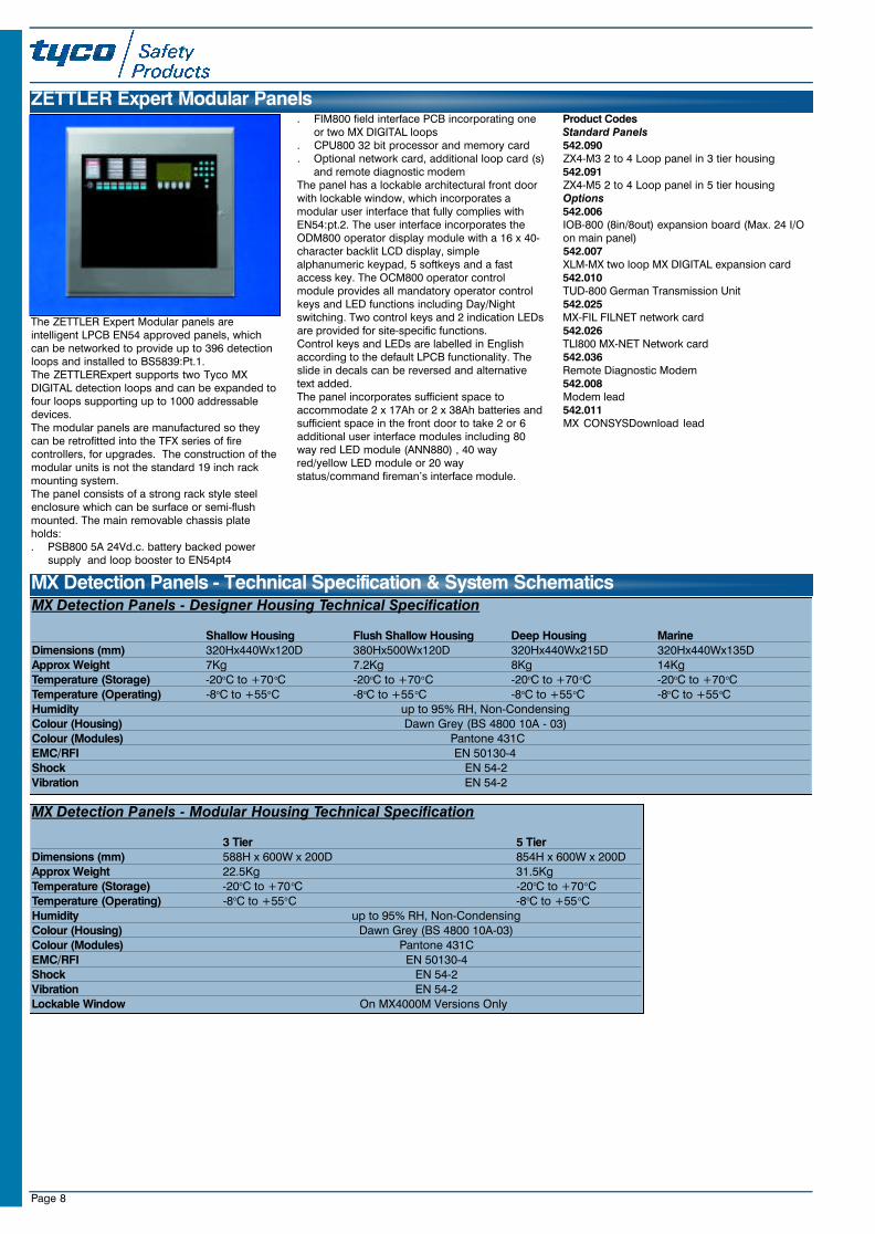
The ZETTLER Expert Modular panels areintelligent LPCB EN54 approved panels, whichcan be networked to provide up to 396 detectionloops and installed to BS5839:Pt.1. The ZETTLERExpert supports two Tyco MXDIGITAL detection loops and can be expanded tofour loops supporting up to 1000 addressabledevices.The modular panels are manufactured so theycan be retrofitted into the TFX series of firecontrollers, for upgrades. The construction of themodular units is not the standard 19 inch rackmounting system.The panel consists of a strong rack style steelenclosure which can be surface or semi-flushmounted. The main removable chassis plateholds:. PSB800 5A 24Vd.c. battery backed power
supply and loop booster to EN54pt4
. FIM800 field interface PCB incorporating oneor two MX DIGITAL loops
. CPU800 32 bit processor and memory card
. Optional network card, additional loop card (s)and remote diagnostic modem
The panel has a lockable architectural front doorwith lockable window, which incorporates amodular user interface that fully complies withEN54:pt.2. The user interface incorporates theODM800 operator display module with a 16 x 40-character backlit LCD display, simplealphanumeric keypad, 5 softkeys and a fastaccess key. The OCM800 operator controlmodule provides all mandatory operator controlkeys and LED functions including Day/Nightswitching. Two control keys and 2 indication LEDsare provided for site-specific functions.Control keys and LEDs are labelled in Englishaccording to the default LPCB functionality. Theslide in decals can be reversed and alternativetext added.The panel incorporates sufficient space toaccommodate 2 x 17Ah or 2 x 38Ah batteries andsufficient space in the front door to take 2 or 6additional user interface modules including 80way red LED module (ANN880) , 40 wayred/yellow LED module or 20 waystatus/command fireman’s interface module.
Product CodesStandard Panels542.090ZX4-M3 2 to 4 Loop panel in 3 tier housing542.091ZX4-M5 2 to 4 Loop panel in 5 tier housingOptions542.006IOB-800 (8in/8out) expansion board (Max. 24 I/Oon main panel)542.007XLM-MX two loop MX DIGITAL expansion card542.010TUD-800 German Transmission Unit542.025MX-FIL FILNET network card542.026TLI800 MX-NET Network card542.036Remote Diagnostic Modem542.008Modem lead542.011MX CONSYSDownload lead
ZETTLER Expert Modular Panels
MX Detection Panels - Modular Housing Technical Specification
3 Tier 5 TierDimensions (mm) 588H x 600W x 200D 854H x 600W x 200DApprox Weight 22.5Kg 31.5KgTemperature (Storage) -20oC to +70oC -20oC to +70oCTemperature (Operating) -8oC to +55oC -8oC to +55oCHumidity up to 95% RH, Non-CondensingColour (Housing) Dawn Grey (BS 4800 10A-03)Colour (Modules) Pantone 431CEMC/RFI EN 50130-4Shock EN 54-2Vibration EN 54-2Lockable Window On MX4000M Versions Only
23SeptMXCat. qxd 11/10/02 11:42 pm Page 8
Page 9
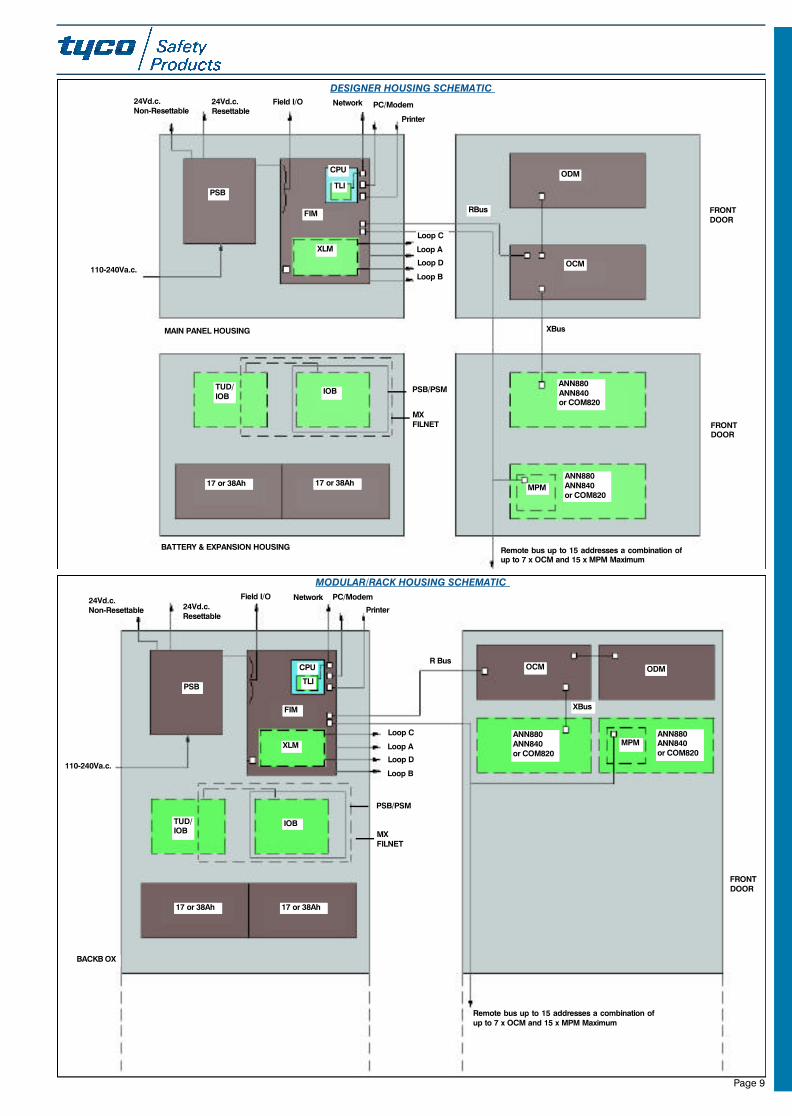
DESIGNER HOUSING SCHEMATIC24Vd.c.Non-Resettable
24Vd.c.Resettable
Field I/O Network PC/Modem
Printer
Loop C
Loop A
Loop D
Loop B
TLI
CPU
FIM
XLM
PSB
110-240Va.c.
RBus
ODM
OCM
XBus
IOBT U D /IOB
17 or 38Ah 17 or 38Ah
ANN880ANN840or COM820
ANN880ANN840or COM820
MPM
Remote bus up to 15 addresses a combination ofup to 7 x OCM and 15 x MPM Maximum
PSB/PSM
MXFILNET
BATTERY & EXPANSION HOUSING
MAIN PANEL HOUSING
MODULAR/RACK HOUSING SCHEMATIC
24Vd.c.Non-Resettable 24Vd.c.
Resettable
Field I/O Network
Printer
PC/Modem
Loop C
Loop A
Loop D
Loop B
TLI
CPU
FIM
XLM
PSB
110-240Va.c.
ODMOCM
XBus
IOBT U D /IOB
17 or 38Ah 17 or 38Ah
ANN880ANN840or COM820
ANN880ANN840or COM820
MPM
Remote bus up to 15 addresses a combination ofup to 7 x OCM and 15 x MPM Maximum
PSB/PSM
MXFILNET
BACKB OX
FRONTDOOR
FRONTDOOR
FRONTDOOR
R Bus
23SeptMXCat. qxd 11/10/02 11:42 pm Page 9
Page 10
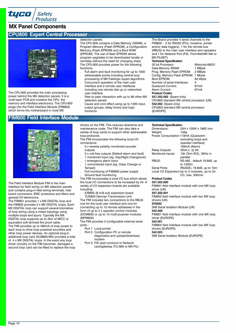
The CPU-800 provides the main processingpower behind the MX detection panels. It is amulti-layer PCB and contains the CPU, thememory and interface electronics. The CPU-800plugs into the Field Interface Module (FIM800)which forms the motherboard in most MX
detection panels. The CPU-800 contains a Data Memory (SRAM), aProgram Memory (Flash EPROM), a ConfigurationMemory (Flash EPROM) and a Boot ROM(EPROM). The use of flash EPROM allowsprogram upgrades to be downloaded locally orremotely without the need for changing chips.The CPU-800 provides power for the followingfunctions:. Full alarm and fault monitoring for up to 1000
addressable points including central loopprocessing of MX Fastlogic expert algorithms
. Concurrent operation of the main userinterface and 2 remote user interfacesincluding one remote dial up or networkeduser interface
. Peer to peer interaction with up to 99 other MXdetection panels
. Cause and core effect using up to 1000 input,output groups, delay timers and logicfunctions
The Board provides 4 serial channels to theFIM800 - 2 for RS232 (PCs, modems, printerand/or data loggers), 1 for the remote bus(RBUS) to the main user interface and repeatersand 1 for Network Port (FSI, ThornNet/MX Net orMX-FILNET)Technical Specification32 bit Processor: Motorola 68331Data Memory SRAM: 1 MByteProg. Memory Flash EPROM: 2 MByteConfig. Memory Flash EPROM: 1 MbyteBoot EPROM: 64 kByteNumber of serial Interfaces: 4Quiescent Current: 67mAAlarm Current: 67mAProduct Codes557.202.002 (Spare only)CPU800 standard MX central processor (UK)542.002 (Spare only)CPU800 standard MX central processor(EUROPE)
CPU800 Expert Central Processor
MX Panel Components
The Field Interface Module FIM is the maininterface for field wiring on MX detection panelsand contains plug-in field wiring terminals, interboard connectors, EMC protectors and filters andgeneral I/O electronics. The FIM801 provides 1 x MX DIGITAL loop andthe FIM802 provides 2 x MX DIGITAL loops. EachMX DIGITAL loop can support several kilometresof loop wiring using a mixed topology usingmultiple loops and spurs. Typically the MXDIGITAL loop supports up to 2km of MICC orequivalent soft skinned fire proof cable.The FIM provides up to 495mA of loop power toeach loop to drive loop powered sounders andother loop power devices. An optional plug-inadditional loop card (XLM800-MX) provides a totalof 4 x MX DIGITAL loops. In the event any loopdriver circuitry on the FIM becomes damaged asecond loop card can be fitted to replace the loop
drivers on the FIM. This reduces downtime andmaintenance costs. The FIM can also take avariety of loop cards to support other addressableloop protocols.The FIM incorporates the following local I/Oconnections:. 2 x reverse polarity monitored sounder
outputs. 2 x volt free outputs (Default alarm and fault). 1 monitored input (eg. Day/Night changeover). 1 emergency alarm input. 1 unmonitored input (eg. Class Change or
Tamper). Full monitoring of PSB800 power supply. Ground fault monitoringThe FIM incorporates a local I/O bus which allowsthe local I/O connections to be increased by 24. Avariety of I/O expansion boards are availableincluding:. IOB800 (8 in/8 out) expansion board . TUD800 German Transmission UnitThe FIM includes two connections to the RBUSone for the local user interface and one forconnecting up to 15 remote addresses in theform of up to 2 x operator control modules(OCM800) or up to 15 multi-purpose modules(MPM800).The FIM provides 3 configurable external serialports :. Port 1 Local printer. Port 2 Configuration PC or remote
diagnostics and upload/download modem
. Port 3 FSI open protocol or Network card/gateway (TLI-800 or MX-FIL)
Technical SpecificationDimensions: 25H x 105W x 196D mmWeight: 156gPower Consumption:119mA (Quiescent -
excluding loops and operator interface)169mA (Alarm)
Relay Outputs: 30Vd.c. @ 2AMonitored inputs: 10k Ohm EOL, 3KHz in
parallelRBUS: RS-485 , default 19.6kB, up
to 1200mSerial Ports: RS232C, 19.6kB, up to 10mLocal I/O Expansion:Up to 2 modules, up to 24
I/O, max. 300mmProduct Codes557.202.000FIM801 field interface module with one MX loopdriver (UK)557.202.001FIM802 field interface module with two MX loopdrivers (UK)976262SIM Serial Isolation Module (UK)542.000FIM801 field interface module with one MX loopdriver (EUROPE)542.001FIM802 field interface module with two MX loopdrivers (EUROPE)542.023SIM Serial Isolation Module (EUROPE)
FIM800 Field Interface Module
23SeptMXCat. qxd 11/10/02 11:42 pm Page 10
Page 11
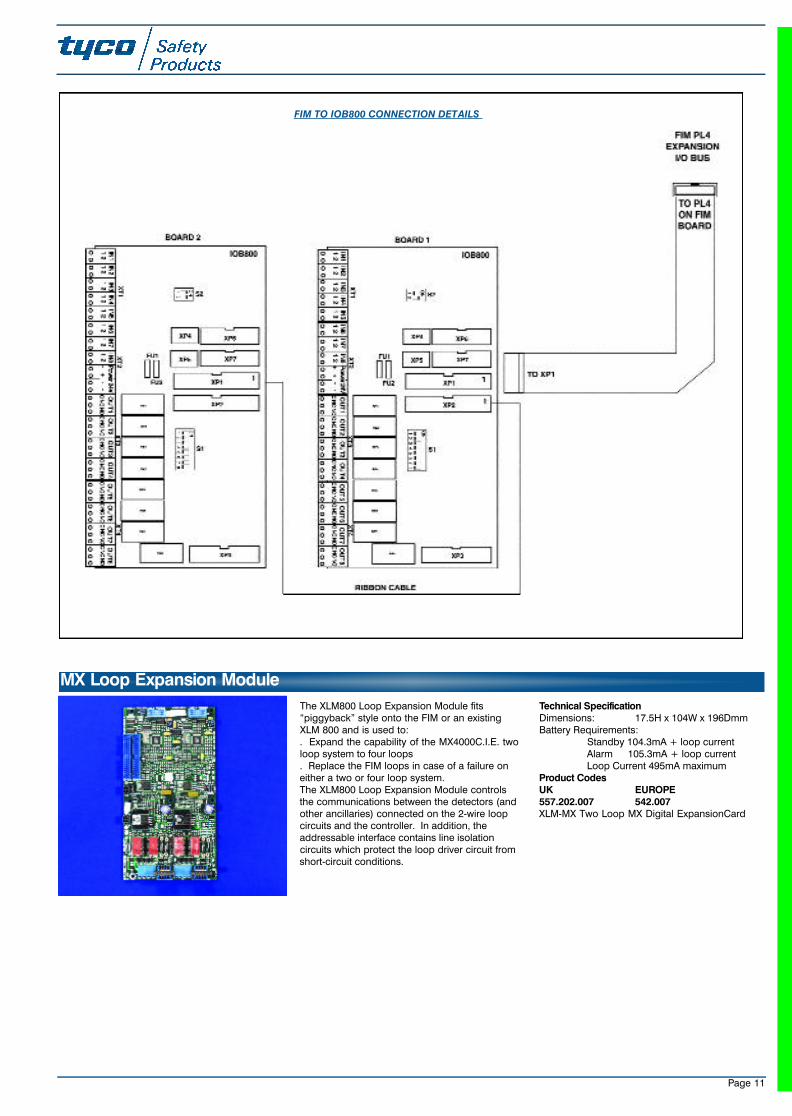
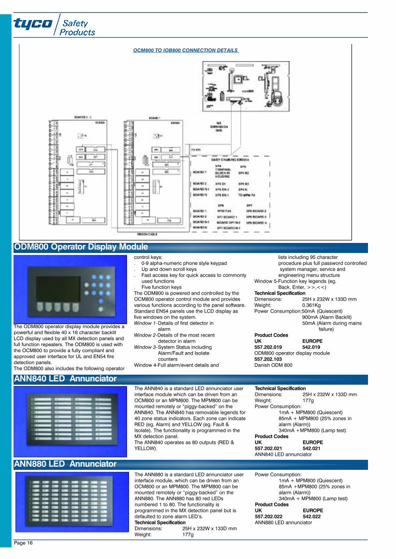
FIM TO IOB800 CONNECTION DETAILS
MX Loop Expansion Module
The XLM800 Loop Expansion Module fits“piggyback” style onto the FIM or an existingXLM 800 and is used to:. Expand the capability of the MX4000C.I.E. twoloop system to four loops. Replace the FIM loops in case of a failure oneither a two or four loop system. The XLM800 Loop Expansion Module controlsthe communications between the detectors (andother ancillaries) connected on the 2-wire loopcircuits and the controller. In addition, theaddressable interface contains line isolationcircuits which protect the loop driver circuit fromshort-circuit conditions.
Technical SpecificationDimensions: 17.5H x 104W x 196DmmBattery Requirements:
Standby 104.3mA + loop currentAlarm 105.3mA + loop currentLoop Current 495mA maximum
Product CodesUK EUROPE557.202.007 542.007XLM-MX Two Loop MX Digital ExpansionCard
23SeptMXCat. qxd 11/10/02 11:42 pm Page 11
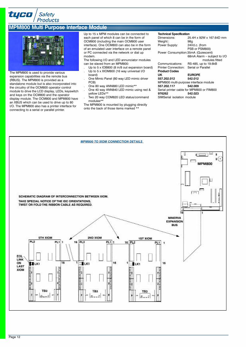
The MPM800 is used to provide variousexpansion capabilities via the remote bus(RBUS). The MPM800 is provided as astandalone module but is also incorporated intothe circuitry of the OCM800 operator controlmodule to drive the LCD display, LEDs, keyswitchand keys on the OCM800 and the operatordisplay module. The OCM800 and MPM800 havean XBUS which can be used to drive up to 80I/O. The MPM800 also has a printer interface forconnecting to a serial or parallel printer.
Up to 15 x MPM modules can be connected toeach panel of which 8 can be in the form ofOCM800 (including the main OCM800 userinterface). One OCM800 can also be in the formof an emulated user interface on a remote panelor PC connected via the network or dial upmodem.The following I/O and LED annunciator modulescan be slaved from an MPM800:. Up to 5 x IOB800 (8 in/8 out expansion board). Up to 5 x XIOM800 (16 way universal I/O
board). One Mimic Panel (80 way LED mimic driver
PCB). One 80 way ANN880 LED mimic**. One 40 way ANN840 LED mimic using red &
yellow LEDs**. Two 20 way COM820 LED status/command
modules**The MPM800 is mounted by plugging directlyonto the back of those items marked **
Technical SpecificationDimensions: 25.4H x 92W x 167.64D mmWeight:: 98gPower Supply: 24Vd.c. (from
PSB or PSM800)Power Consumption:35mA (Quiescent)
68mA Alarm – subject to I/Omodules fitted
Communications: RS-485, up to 19.6kBPrinter Connection: Serial or ParallelProduct CodesUK EUROPE557.202.012 542.012MPM800 multi-purpose interface module 557.202.117 542.009Serial printer cable for MPM800 or FIM800976262 542.023SIMSerial isolation module
MPM800 Multi Purpose Interface Module
Page 12
MPM800 TO XIOM CONNECTION DETAILS
23SeptMXCat. qxd 11/10/02 11:42 pm Page 12
The MX power supply module is a state-of-the-artintegrated switch mode system power supply andbattery charger, which can provide up to 5Aexternal and auxiliary loop power during alarmconditions. It has a universal input allowingoperation from 100 to 255 Va.c., 50 or 60 Hz. Thepower supply is approved* worldwide to EN54,UL864 and Marine standards.The charging voltage is temperaturecompensated. The PSM recharges the batterieswithin 24 h for the following timings:. 90h stand by time and 15 min. alarm condition. 72h stand by time and 30min. alarm conditionThe power supply provides full condition and faultmonitoring to the system via the FIM (used by thePSB800) or addressable power supply monitorAPM800 (used by the PSM800). The PSB800incorporates the LBM800 booster module toprovide the correct voltage levels to maximise theperformance of the MX DIGITAL protocol.Faults signals (Loss of AC, Battery charger fault,Battery fault) and control inputs (Battery test,
Output reset) are provided. Battery voltage andcharger current readings are also provided to theFIM or APM for automatic battery testing.Screw terminals provide 2 x 24V outputs (24 Vstabilised, 24V stabilised with reset control) andone 5V output.The power supply is fitted in a steel cage withmounting points to allow any of the followingboards to be mounted:. APM800 addressable power supply monitor. FB800 fuse board with 15 x 24Vd.c. fused
spurs. IOB800 input/output expansion boardTechnical SpecificationDimensions: 50H x 114W x 190D mmWeight: 0.9KgInput Voltage: 120-240 Vrms, 50/60Hz
(Auto ranging)Input Current: 0.8-1.6ARMS Rated Load
Max. charge current : Up to 3.8A (dependant on standby current)
Max. battery size(24hr charge): 38AhMax. total supply current: [email protected]. Maximum external current: [email protected] Voltages: 24Vd.c.
(22.8 -26.4V)Non-resettable: 24Vd.c. @ 4AResettable: 24Vd.c. @ 4A
5Vd.c. @ 3APower Consumption:PSB - 90mA
(quiescent & alarm)PSM - 65mA(quiescent & alarm)
A PSB 800K Power Expansion Kit is required topower the XLM 800 pcb on 4 loop systems whichrequire the extended loop power capability. It
consists of a PSB800 power supply module thatcomes with a loop booster module, an APM 800addressable monitor module, a batteryconnecting cable and an XLM800 to APM800connecting cable and maybe fitted onto thechassis plate in the battery housing.
Product CodesUK EUROPE557.200.014 542.088MXAPSU17 Boxed Addressable PSU (17Ah) 557.200.015 542.089MXAPSU38 Boxed Addressable PSU (38Ah)Options557.202.003 542.003PSM800 Power Supply Only557.202.403 NAPSM800M Marine approved power supply557.202.005 542.005PSB800 Panel Power Supply c/w Loop Booster557.202.405 NAPSB800M Marine Panel Power Supply (spare)557.202.027 572.018APM800 Addressable Power Supply Monitor557.202.050 NAPSM800 Temp. Sensor Accessory kit557.202.040 542.200PSB800K Power Expansion kit557.202.004LBM800 Spare Loop Voltage Booster PCB
PSM800 and PSB800 Power Supplies
Page 13
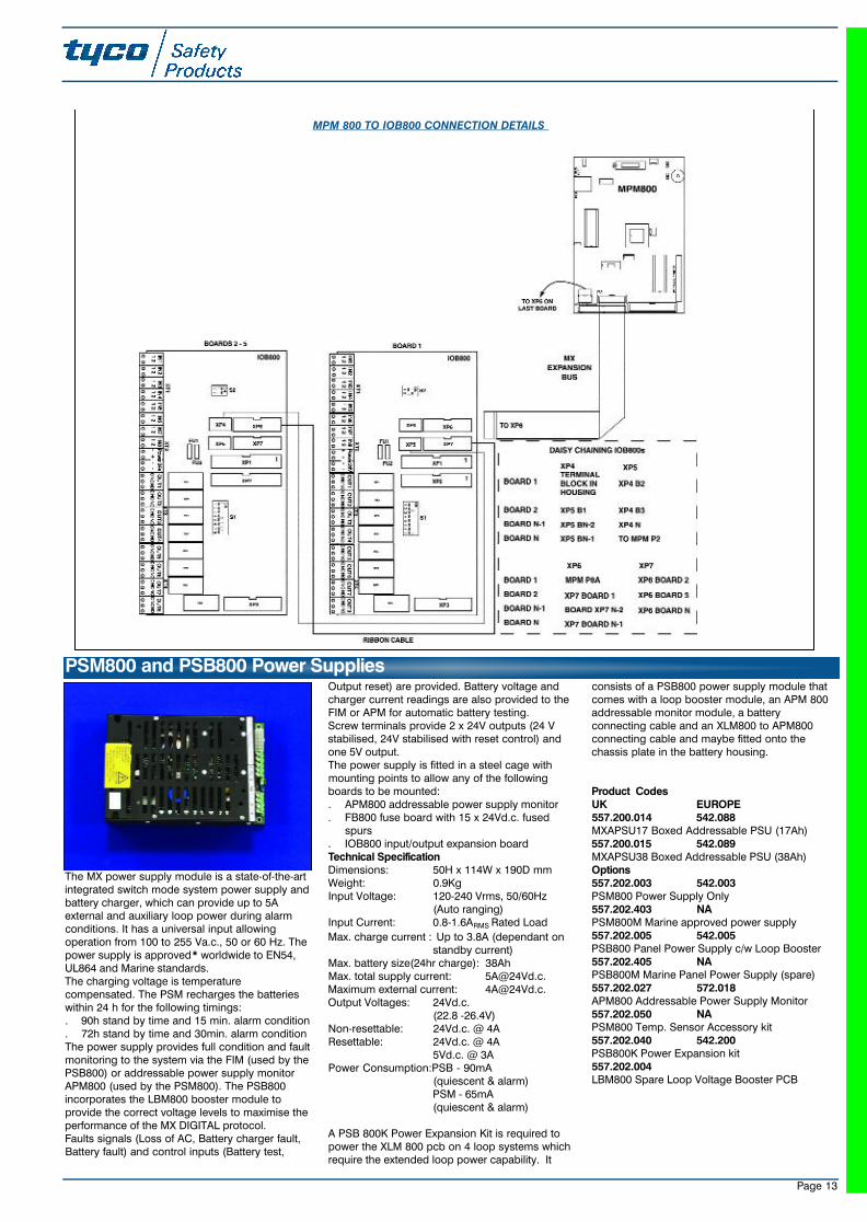
MPM 800 TO IOB800 CONNECTION DETAILS
23SeptMXCat. qxd 11/10/02 11:42 pm Page 13
Page 14
The Filnet Gateway is an EN54 Vds approvednetwork gateway which allows up to 64 MXPanels to be networked onto a secure LONbasedFILNET Network.The MX-FIL Gateway can be mounted in thedesigner battery box on the chassis plate or theinside of the modular housing.
Technical SpecificationDimensions: 135H x 280W x 35D mmWeight (Approx): 330gSerial interfaces (electr. isolated):
- No. Interfaces: 1- Parameters (coding plugs):
RS 232 / 422 / 485- Baud Rates: Programmable
LON-interface (incl. NIF):- No. Interfaces: 2- Parameter FTT10 transceiver- Baud Rate: 78 kbit/s
Voltage Supply:- From control panel or external PS:
0V / +24Vd.c.- Monitoring with XPSUMB:
0V / +5V / +24Vd.c.Power Consumption:
- External interface gateway typ: 80 mA
Digital Outputs (short circuit proof):- Number of open collector outputs: 8- Current limitation: 50 mA
Digital Inputs (overvolt. prot):- Number of electr. isolated inputs: 8- Series resistance to the opto-coupler
LED 4.7 kohm- Input voltage range 5 - 28 V
Product CodesUK EUROPE557.202.025 542.025MX-FILFilnet Gateway
MX-FIL Filnet Gateway
The IOB800 is an LPCB & Vds approved* boardthat provides 8 opto-isolated digital inputs and 8 x24V d.c. relay outputs for providing I/O expansioncapabilities to MX detection panels for interfacingto other subsystems and signalling devices. TheIOB800 also incorporates a connector, which pro-vides decoded signals for the 8 inputs and 8 out-puts for specialist interfacing.The IOB800 can be used to provide expansion I/Oto the following MX panel components:. FIM801/802 field interface modules (maximum
16In/8Out). OCM800 operator control modules (maximum
80 I/O). MPM800 multi-purpose interface (maximum 80
I/O)
The IOB800 can be mounted on the PSB800 panelpower supply, up to two in the top of a battery boxor repeater or in the back of a modular housing.The IOB800 has two expansion bus connectorswhich allow them to be daisy chained together.Technical SpecificationDimensions: 15H X 164W X 80D mmWeight: 153gPower Consumption:29mA (Quiescent)
65mA (Maximum)Terminations: 1.5mmProduct CodesUK EUROPE557.202.006 542.006IOB800 Expansion Board and cables
IOB800 Input/Output Expansion Board
The TUD800 is a VdS approved* input/outputmodule specifically designed for interfacing theZETTLER EXPERT panels to the German FireBrigade equipment.The TUD800 takes the place of an IOB800 whenused and is typically mounted in the deepbattery/expansion box.Technical SpecificationDimensions: 15H x 164W x 80D mmWeight: 153gPower Consumption:29mA (Quiescent)
65mA (Alarm)
Product CodesEUROPE542.010TUD800 German Transmission Unit
TUD800 German Transmission Unit
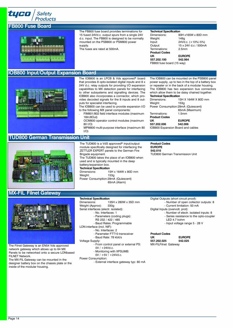
The FB800 fuse board provides terminations for15 fused 24Vd.c. output spurs from a single 24Vd.c. input. The FB800 is designed to be normallymounted on the PSB800 or PSM800 powersupply.The fuses are rated at 500mA.
Technical SpecificationDimensions: 93H x165W x 80D mmWeight: 149gInput: 24Vd.c. (+10%/-5%)Output: 15 x 24V d.c / 500mATerminations: 2.5mmProduct CodesUK EUROPE557.202.100 542.064FB800 fuse board (15 way)
FB800 Fuse Board
23SeptMXCat. qxd 11/10/02 11:42 pm Page 14
Page 15
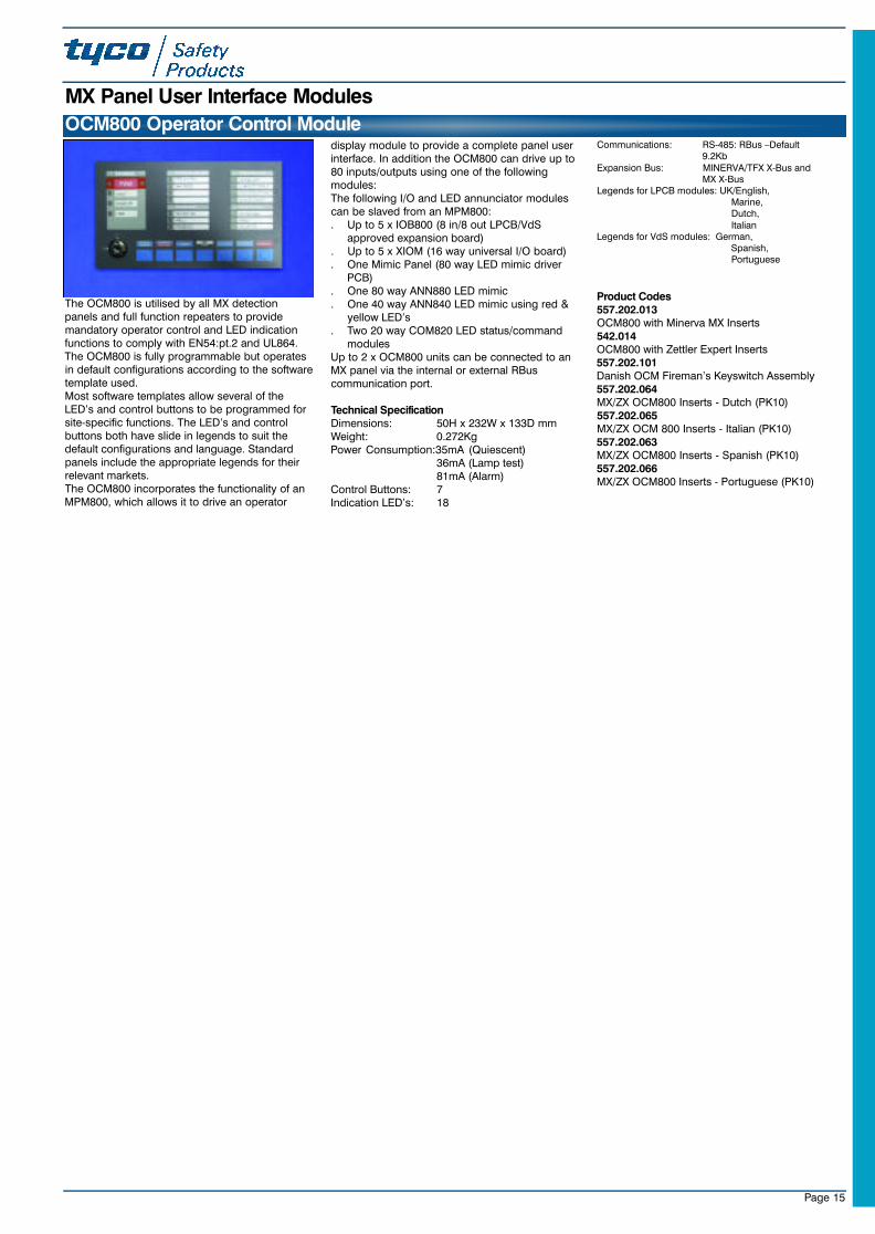
The OCM800 is utilised by all MX detectionpanels and full function repeaters to providemandatory operator control and LED indicationfunctions to comply with EN54:pt.2 and UL864.The OCM800 is fully programmable but operatesin default configurations according to the softwaretemplate used.Most software templates allow several of theLED’s and control buttons to be programmed forsite-specific functions. The LED’s and controlbuttons both have slide in legends to suit thedefault configurations and language. Standardpanels include the appropriate legends for theirrelevant markets.The OCM800 incorporates the functionality of anMPM800, which allows it to drive an operator
display module to provide a complete panel userinterface. In addition the OCM800 can drive up to80 inputs/outputs using one of the followingmodules: The following I/O and LED annunciator modulescan be slaved from an MPM800:. Up to 5 x IOB800 (8 in/8 out LPCB/VdS
approved expansion board). Up to 5 x XIOM (16 way universal I/O board). One Mimic Panel (80 way LED mimic driver
PCB). One 80 way ANN880 LED mimic. One 40 way ANN840 LED mimic using red &
yellow LED’s. Two 20 way COM820 LED status/command
modulesUp to 2 x OCM800 units can be connected to anMX panel via the internal or external RBuscommunication port.
Technical SpecificationDimensions: 50H x 232W x 133D mmWeight: 0.272KgPower Consumption:35mA (Quiescent)
36mA (Lamp test)81mA (Alarm)
Control Buttons: 7Indication LED’s: 18
Communications: RS-485: RBus –Default 9.2Kb
Expansion Bus: MINERVA/TFX X-Bus and MX X-Bus
Legends for LPCB modules: UK/English,Marine,Dutch,Italian
Legends for VdS modules: German,Spanish,Portuguese
Product Codes557.202.013OCM800 with Minerva MX Inserts542.014OCM800 with Zettler Expert Inserts557.202.101Danish OCM Fireman’s Keyswitch Assembly557.202.064MX/ZX OCM800 Inserts - Dutch (PK10)557.202.065MX/ZX OCM 800 Inserts - Italian (PK10)557.202.063MX/ZX OCM800 Inserts - Spanish (PK10)557.202.066MX/ZX OCM800 Inserts - Portuguese (PK10)
OCM800 Operator Control Module
MX Panel User Interface Modules
23SeptMXCat. qxd 11/10/02 11:42 pm Page 15
Page 16
The ANN880 is a standard LED annunciator userinterface module, which can be driven from anOCM800 or an MPM800. The MPM800 can bemounted remotely or “piggy-backed” on theANN880. The ANN880 has 80 red LEDsnumbered 1 to 80. The functionality isprogrammed in the MX detection panel but isdefaulted to zone alarm LED’s.Technical SpecificationDimensions: 25H x 232W x 133D mmWeight: 177g
Power Consumption: 1mA + MPM800 (Quiescent)85mA +MPM800 (25% zones in alarm (Alarm))340mA + MPM800 (Lamp test)
Product CodesUK EUROPE557.202.022 542.022ANN880 LED annunciator
The ANN840 is a standard LED annunciator userinterface module which can be driven from anOCM800 or an MPM800. The MPM800 can bemounted remotely or “piggy-backed” on theANN840. The ANN840 has removable legends for40 zone status indicators. Each zone can indicateRED (eg. Alarm) and YELLOW (eg. Fault &Isolate). The functionality is programmed in theMX detection panel.The ANN840 operates as 80 outputs (RED &YELLOW).
Technical SpecificationDimensions: 25H x 232W x 133D mmWeight: 177gPower Consumption:
1mA + MPM800 (Quiescent)85mA + MPM800 (25% zones in alarm (Alarm))340mA +MPM800 (Lamp test)
Product CodesUK EUROPE557.202.021 542.021ANN840 LED annunciator
The ODM800 operator display module provides apowerful and flexible 40 x 16 character backlitLCD display used by all MX detection panels andfull function repeaters. The ODM800 is used withthe OCM800 to provide a fully compliant andapproved user interface for UL and EN54 firedetection panels.The ODM800 also includes the following operator
control keys:. 0-9 alpha-numeric phone style keypad. Up and down scroll keys. Fast access key for quick access to commonly
used functions. Five function keys The ODM800 is powered and controlled by theOCM800 operator control module and providesvarious functions according to the panel software.Standard EN54 panels use the LCD display asfive windows on the system.Window 1-Details of first detector in
alarm Window 2-Details of the most recent
detector in alarmWindow 3-System Status including
Alarm/Fault and Isolate counters
Window 4-Full alarm/event details and
lists including 95 character procedure plus full password controlledsystem manager, service and
engineering menu structureWindow 5-Function key legends (eg.
Back, Enter, >>,<<)Technical SpecificationDimensions: 25H x 232W x 133D mmWeight: 0.361KgPower Consumption:50mA (Quiescent)
900mA (Alarm Backlit)50mA (Alarm during mains
failure)Product CodesUK EUROPE557.202.019 542.019ODM800 operator display module557.202.103Danish ODM 800
ODM800 Operator Display Module
ANN840 LED Annunciator
ANN880 LED Annunciator
OCM800 TO IOB800 CONNECTION DETAILS
23SeptMXCat. qxd 11/10/02 11:42 pm Page 16
Page 17
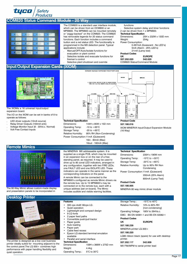
The COM820 is a standard user interface module,which can be driven from an OCM800 or anMPM800. The MPM800 can be mounted remotelyor “piggy-backed” on the COM820. The COM820has removable legends for 20 status commandfunctions. Each function includes a commandbutton and a red status LED. The functionality isprogrammed in the MX detection panel. Typicalapplications include:. Manual/OFF/Auto/Isolate functions for
evacuation or plant control. Selective isolate and evacuate functions for
fireman’s control. Selective plant shutdown and override
functions. Selective system delay and timer functions2 can be driven from 1 x MPM800.Technical SpecificationDimensions: 25H x 232W x 133D mmWeight: 204gPower Consumption:
0.267mA (Quiescent - No LED’s)5mA (Alarm - 25% LED’s)21mA (Lamp test)
Product CodesUK EUROPE557.202.020 542.020COM820 Status/Command Module
COM820 Status Command Module - 20 Way
Input/Output Expansion Cards (XIOM)
The XIOMis a 16 universal input/outputexpansion board.
The I/O on the XIOM can be set in banks of 8 tooperate as follows:
. LED driver outputs (10mA source)
. Relay Driver Outputs (100mA sink)
. Voltage Monitor Input (8 - 30Vd.c. Normal)
. Volt Free Contact inputs
Technical Specification
Dimensions: 144H x 85W x 15D mm
Operating Temp: -10 to +65°C
Storage Temp: -20 to +65°C
Relative Humidity: 95% RH (Non-Condensing)
Power Consumption:11mA (Quiescent)
16in - 80mA (Max)
16out - 160mA (Max)
Product Code
557.180.016
XIOM MINERVA Input/Output Expansion Module(16 Way)
The 80-Way Mimic allows custom-made displayand presentation panels to be incorporated in
the MINERVA MX addressable system. It issupplied as a single PCB, which may be mountedin an expansion box or on the rear of a free-standing panel, as required. It may be used todrive up to 80 zonal LED indicators, arranged inany configuration, together with two FIRE LEDs,one FAULT LED and one ISOLATE LED. Theseindicators can operate in the same manner as thecorresponding indicators on the panel.
A remote Mimic can be connected to theMPM800’s configured as remote Mimic drivers viathe remote bus. Up to 15 MPM800’s may beconnected on to the remote bus, each with aunique address [set on-board]. The Mimicincludes audible and visible warning facilities.
Technical Specification
Dimensions: 235H x 190W mm
Operating Temp: -10°C to +55°C
Storage Temp: -20°C to +65°C
Relative Humidity: Up to 95% RH Non Condensing
Power Consumption:11mA (Quiescent)
200mA (25% Alarm)
800mA (Lamp Test)
Product Code
557.180.005
MINERVA 80 way mimic driver module
Remote Mimics
The printer is designed as a low cost businessprinter ideally suited for mounting adjacent to thefire control panel.The LQ-300+ combines highperformance with paper handling flexibility andquiet operation.
Features
• 300 cps draft/ 90cps LQ.• Quiet operation• Lightweight and compact design• 9 LQ fonts• 2 paper feed paths• Convertible push/pull tractor• Paper guide• Auto loading• Paper park• Cable feed recess• Epson LQ standard terminal emulation
available• Parallel and serial interfaceTechnical SpecificationDimensions: 159H x 366W x 275D mm
Weight: 4.4kg
Operating Temp.: 5°C to 35°C
Storage Temp.: -15°C to 40°C
Relative Humidity: 10% to 80% RH [non-condensing]
Operating Voltage: 180V to 264Va.c.
EMC: BS EN 50081-1 and BS EN 50082-1
Product Codes
UK EUROPE
557.180.239
MINERVA printer LQ-300+
557.180.220
LQ80 ribbon black (spare) for use with desktopprinter.
557.202.117 542.009
MX FIM/MPM to serial printer lead
Desktop Printer
23SeptMXCat. qxd 11/10/02 11:42 pm Page 17
Page 18
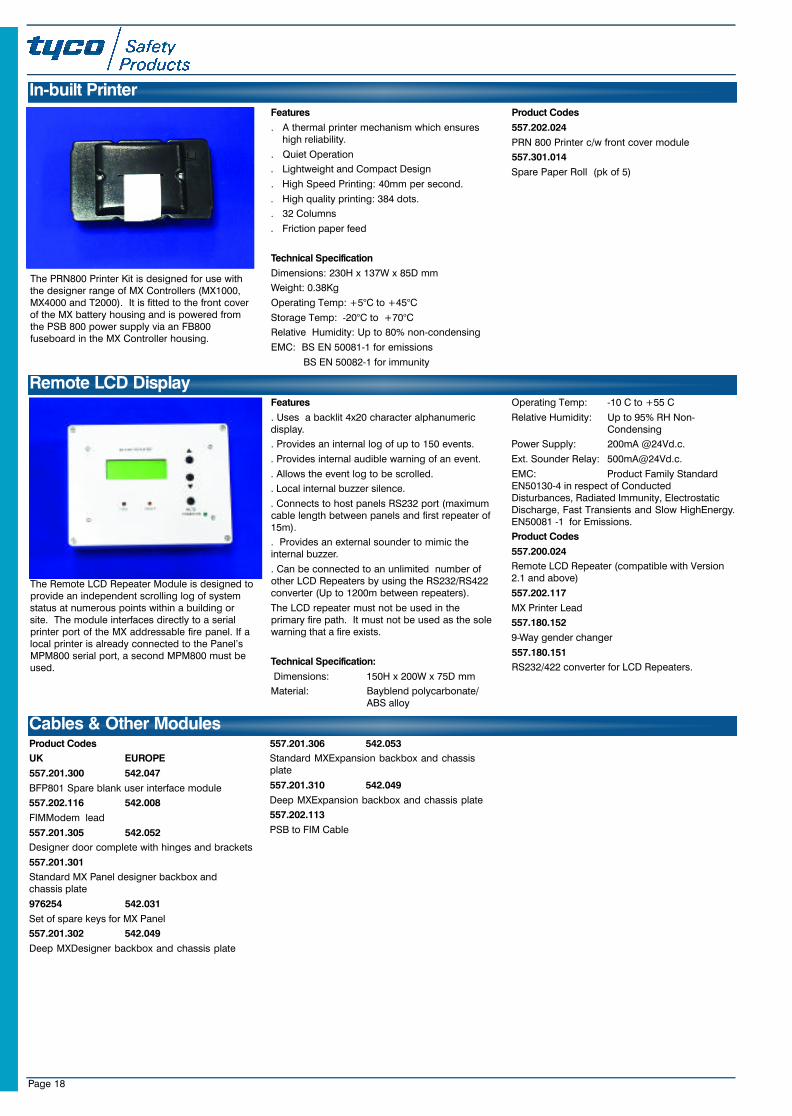
The PRN800 Printer Kit is designed for use withthe designer range of MX Controllers (MX1000,MX4000 and T2000). It is fitted to the front coverof the MX battery housing and is powered fromthe PSB 800 power supply via an FB800fuseboard in the MX Controller housing.
Features
. A thermal printer mechanism which ensures high reliability.
. Quiet Operation
. Lightweight and Compact Design
. High Speed Printing: 40mm per second.
. High quality printing: 384 dots.
. 32 Columns
. Friction paper feed
Technical Specification
Dimensions: 230H x 137W x 85D mm
Weight: 0.38Kg
Operating Temp: +5°C to +45°C
Storage Temp: -20°C to +70°C
Relative Humidity: Up to 80% non-condensing
EMC: BS EN 50081-1 for emissions
BS EN 50082-1 for immunity
Product Codes
557.202.024
PRN 800 Printer c/w front cover module
557.301.014
Spare Paper Roll (pk of 5)
Product Codes
UK EUROPE
557.201.300 542.047
BFP801 Spare blank user interface module
557.202.116 542.008
FIMModem lead
557.201.305 542.052
Designer door complete with hinges and brackets
557.201.301
Standard MX Panel designer backbox andchassis plate
976254 542.031
Set of spare keys for MX Panel
557.201.302 542.049
Deep MXDesigner backbox and chassis plate
557.201.306 542.053
Standard MXExpansion backbox and chassisplate
557.201.310 542.049
Deep MXExpansion backbox and chassis plate
557.202.113
PSB to FIM Cable
Cables & Other Modules
In-built Printer
Remote LCD Display
The Remote LCD Repeater Module is designed toprovide an independent scrolling log of systemstatus at numerous points within a building orsite. The module interfaces directly to a serialprinter port of the MX addressable fire panel. If alocal printer is already connected to the Panel’sMPM800 serial port, a second MPM800 must beused.
Features
. Uses a backlit 4x20 character alphanumericdisplay.
. Provides an internal log of up to 150 events.
. Provides internal audible warning of an event.
. Allows the event log to be scrolled.
. Local internal buzzer silence.
. Connects to host panels RS232 port (maximumcable length between panels and first repeater of15m).
. Provides an external sounder to mimic theinternal buzzer.
. Can be connected to an unlimited number ofother LCD Repeaters by using the RS232/RS422converter (Up to 1200m between repeaters).
The LCD repeater must not be used in theprimary fire path. It must not be used as the solewarning that a fire exists.
Technical Specification:
Dimensions: 150H x 200W x 75D mm
Material: Bayblend polycarbonate/ABS alloy
Operating Temp: -10 C to +55 C
Relative Humidity: Up to 95% RH Non-Condensing
Power Supply: 200mA @24Vd.c.
Ext. Sounder Relay: [email protected].
EMC: Product Family StandardEN50130-4 in respect of ConductedDisturbances, Radiated Immunity, ElectrostaticDischarge, Fast Transients and Slow HighEnergy.EN50081 -1 for Emissions.
Product Codes
557.200.024
Remote LCD Repeater (compatible with Version2.1 and above)
557.202.117
MX Printer Lead
557.180.152
9-Way gender changer
557.180.151
RS232/422 converter for LCD Repeaters.
23SeptMXCat. qxd 11/10/02 11:42 pm Page 18
Page 19
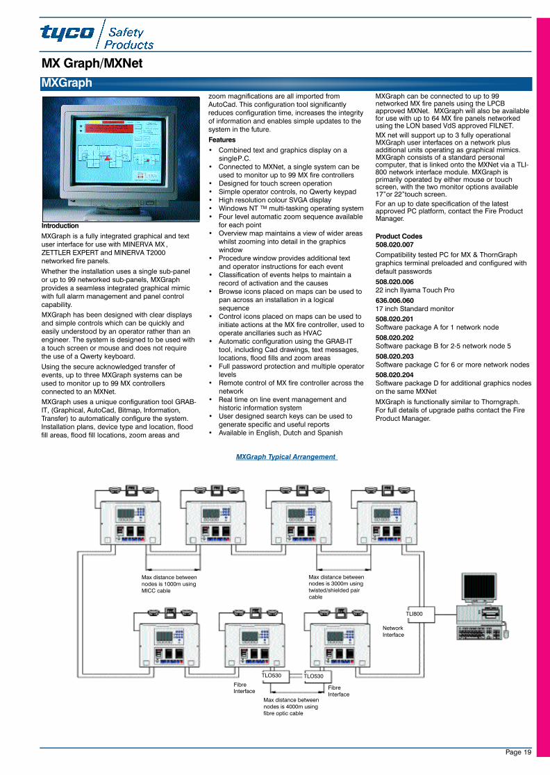
Introduction
MXGraph is a fully integrated graphical and textuser interface for use with MINERVA MX ,ZETTLER EXPERT and MINERVA T2000networked fire panels.
Whether the installation uses a single sub-panelor up to 99 networked sub-panels, MXGraphprovides a seamless integrated graphical mimicwith full alarm management and panel controlcapability.
MXGraph has been designed with clear displaysand simple controls which can be quickly andeasily understood by an operator rather than anengineer. The system is designed to be used witha touch screen or mouse and does not requirethe use of a Qwerty keyboard.
Using the secure acknowledged transfer ofevents, up to three MXGraph systems can beused to monitor up to 99 MX controllersconnected to an MXNet.
MXGraph uses a unique configuration tool GRAB-IT, (Graphical, AutoCad, Bitmap, Information,Transfer) to automatically configure the system.Installation plans, device type and location, floodfill areas, flood fill locations, zoom areas and
zoom magnifications are all imported fromAutoCad. This configuration tool significantlyreduces configuration time, increases the integrityof information and enables simple updates to thesystem in the future.
Features
• Combined text and graphics display on asingle P.C.
• Connected to MXNet, a single system can beused to monitor up to 99 MX fire controllers
• Designed for touch screen operation• Simple operator controls, no Qwerty keypad• High resolution colour SVGA display• Windows NT TM multi-tasking operating system• Four level automatic zoom sequence available
for each point• Overview map maintains a view of wider areas
whilst zooming into detail in the graphicswindow
• Procedure window provides additional textand operator instructions for each event
• Classification of events helps to maintain arecord of activation and the causes
• Browse icons placed on maps can be used topan across an installation in a logicalsequence
• Control icons placed on maps can be used toinitiate actions at the MX fire controller, used tooperate ancillaries such as HVAC
• Automatic configuration using the GRAB-ITtool, including Cad drawings, text messages,locations, flood fills and zoom areas
• Full password protection and multiple operatorlevels
• Remote control of MX fire controller across thenetwork
• Real time on line event management andhistoric information system
• User designed search keys can be used togenerate specific and useful reports
• Available in English, Dutch and Spanish
MXGraph can be connected to up to 99networked MX fire panels using the LPCBapproved MXNet. MXGraph will also be availablefor use with up to 64 MX fire panels networkedusing the LON based VdS approved FILNET.
MX net will support up to 3 fully operationalMXGraph user interfaces on a network plusadditional units operating as graphical mimics.MXGraph consists of a standard personalcomputer, that is linked onto the MXNet via a TLI-800 network interface module. MXGraph isprimarily operated by either mouse or touchscreen, with the two monitor options available17”or 22”touch screen.
For an up to date specification of the latestapproved PC platform, contact the Fire ProductManager.
Product Codes508.020.007
Compatibility tested PC for MX & ThornGraphgraphics terminal preloaded and configured withdefault passwords
508.020.00622 inch IIyama Touch Pro
636.006.06017 inch Standard monitor
508.020.201Software package A for 1 network node
508.020.202Software package B for 2-5 network node 5
508.020.203Software package C for 6 or more network nodes
508.020.204Software package D for additional graphics nodeson the same MXNet
MXGraph is functionally similar to Thorngraph.For full details of upgrade paths contact the FireProduct Manager.
MXGraph
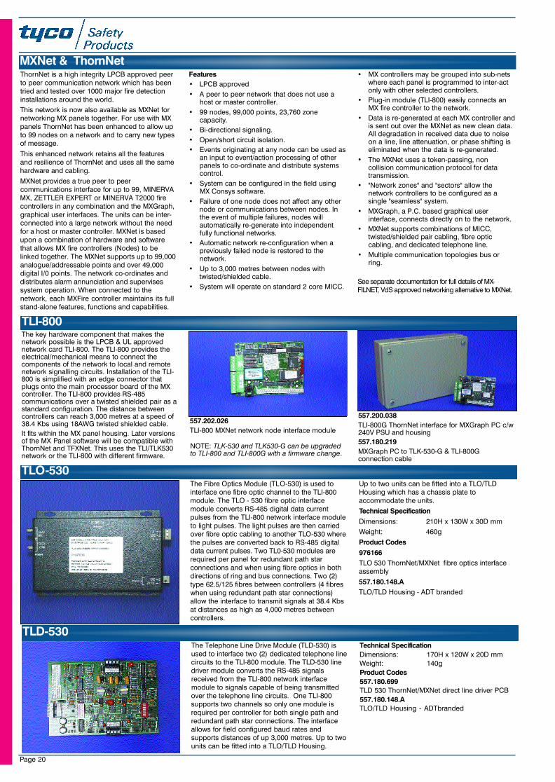
MXGraph Typical Arrangement
Max distance betweennodes is 1000m usingMICC cable
Max distance betweennodes is 3000m usingtwisted/shielded paircable
Max distance betweennodes is 4000m usingfibre optic cable
TLI800
TLO530 TLO530
FibreInterface
FibreInterface
NetworkInterface
MX Graph/MXNet
23SeptMXCat. qxd 11/10/02 11:42 pm Page 19
Page 20
The Telephone Line Drive Module (TLD-530) isused to interface two (2) dedicated telephone linecircuits to the TLI-800 module. The TLD-530 linedriver module converts the RS-485 signalsreceived from the TLI-800 network interfacemodule to signals capable of being transmittedover the telephone line circuits. One TLI-800supports two channels so only one module isrequired per controller for both single path andredundant path star connections. The interfaceallows for field configured baud rates andsupports distances of up 3,000 metres. Up to twounits can be fitted into a TLO/TLD Housing.
Technical SpecificationDimensions: 170H x 120W x 20D mm Weight: 140gProduct Codes557.180.699TLD 530 ThornNet/MXNet direct line driver PCB557.180.148.ATLO/TLD Housing - ADTbranded
ThornNet is a high integrity LPCB approved peerto peer communication network which has beentried and tested over 1000 major fire detectioninstallations around the world.
This network is now also available as MXNet fornetworking MX panels together. For use with MXpanels ThornNet has been enhanced to allow upto 99 nodes on a network and to carry new typesof message.
This enhanced network retains all the featuresand resilience of ThornNet and uses all the samehardware and cabling.
MXNet provides a true peer to peercommunications interface for up to 99, MINERVAMX, ZETTLER EXPERT or MINERVA T2000 firecontrollers in any combination and the MXGraph,graphical user interfaces. The units can be inter-connected into a large network without the needfor a host or master controller. MXNet is basedupon a combination of hardware and softwarethat allows MX fire controllers (Nodes) to belinked together. The MXNet supports up to 99,000analogue/addressable points and over 49,000digital I/0 points. The network co-ordinates anddistributes alarm annunciation and supervisessystem operation. When connected to thenetwork, each MXFire controller maintains its fullstand-alone features, functions and capabilities.
Features
• LPCB approved
• A peer to peer network that does not use ahost or master controller.
• 99 nodes, 99,000 points, 23,760 zonecapacity.
• Bi-directional signaling.
• Open/short circuit isolation.
• Events originating at any node can be used asan input to event/action processing of otherpanels to co-ordinate and distribute systemscontrol.
• System can be configured in the field usingMX Consys software.
• Failure of one node does not affect any othernode or communications between nodes. Inthe event of multiple failures, nodes willautomatically re-generate into independentfully functional networks.
• Automatic network re-configuration when apreviously failed node is restored to thenetwork.
• Up to 3,000 metres between nodes withtwisted/shielded cable.
• System will operate on standard 2 core MICC.
• MX controllers may be grouped into sub-netswhere each panel is programmed to inter-actonly with other selected controllers.
• Plug-in module (TLI-800) easily connects anMX fire controller to the network.
• Data is re-generated at each MX controller andis sent out over the MXNet as new clean data.All degradation in received data due to noiseon a line, line attenuation, or phase shifting iseliminated when the data is re-generated.
• The MXNet uses a token-passing, noncollision communication protocol for datatransmission.
• "Network zones" and "sectors" allow thenetwork controllers to be configured as asingle "seamless" system.
• MXGraph, a P.C. based graphical userinterface, connects directly on to the network.
• MXNet supports combinations of MICC,twisted/shielded pair cabling, fibre opticcabling, and dedicated telephone line.
• Multiple communication topologies bus orring.
See separate documentation for full details of MX-F I L N E T, VdS approved networking alternative to MXNet.
557.200.038
TLI-800G ThornNet interface for MXGraph PC c/w240V PSU and housing
557.180.219
MXGraph PC to TLK-530-G & TLI-800Gconnection cable
MXNet & ThornNet
The Fibre Optics Module (TLO-530) is used tointerface one fibre optic channel to the TLI-800module. The TLO - 530 fibre optic interfacemodule converts RS-485 digital data currentpulses from the TLI-800 network interface moduleto light pulses. The light pulses are then carriedover fibre optic cabling to another TLO-530 wherethe pulses are converted back to RS-485 digitaldata current pulses. Two TL0-530 modules arerequired per panel for redundant path starconnections and when using fibre optics in bothdirections of ring and bus connections. Two (2)type 62.5/125 fibres between controllers (4 fibreswhen using redundant path star connections)allow the interface to transmit signals at 38.4 Kbsat distances as high as 4,000 metres betweencontrollers.
Up to two units can be fitted into a TLO/TLDHousing which has a chassis plate toaccommodate the units.
Technical Specification
Dimensions: 210H x 130W x 30D mm
Weight: 460g
Product Codes
976166
TLO 530 ThornNet/MXNet fibre optics interfaceassembly
557.180.148.A
TLO/TLD Housing - ADT branded
The key hardware component that makes thenetwork possible is the LPCB & UL approvednetwork card TLI-800. The TLI-800 provides theelectrical/mechanical means to connect thecomponents of the network to local and remotenetwork signalling circuits. Installation of the TLI-800 is simplified with an edge connector thatplugs onto the main processor board of the MXcontroller. The TLI-800 provides RS-485communications over a twisted shielded pair as astandard configuration. The distance betweencontrollers can reach 3,000 metres at a speed of38.4 Kbs using 18AWG twisted shielded cable.
It fits within the MX panel housing. Later versionsof the MX Panel software will be compatible withThornNet and TFXNet. This uses the TLI/TLK530network or the TLI-800 with different firmware.
TLI-800
557.202.026
TLI-800 MXNet network node interface module
TLO-530
TLD-530
NOTE: TLK-530 and TLK530-G can be upgradedto TLI-800 and TLI-800G with a firmware change.
23SeptMXCat. qxd 11/10/02 11:42 pm Page 20
Page 21
Features. Single MX DIGITAL loop 8 to 16 zone detection
panel. LPCB approved to EN54:pt.2 and pt.4. Auxiliary loop power. MX VIRTUAL detectors . Fully programmable with front panel
programming option. Optional integral event printer. 2 x 40 Character text display. Pre-alarm functions. Display of temperature, CO and smoke levels. Supports day/night detection modes. Supports MXSOLO Remote diagnostics. Optional full function repeaters. Optional service upgrade universal loop card
The MINERVA SOLO use Tyco MX technology toprovide a highly featured yet cost effective firedetection panel. The MINERVA SOLO is a single loop LPCB approvedEN54 detection panel available in 8 and 16 zonemodels.MINERVA SOLO panels provide a highly featured andfully approved alternative to conventional detectionsystems in small to medium multi-occupancy,commercial and industrial buildings. The MINERV ASOLO also allows systems with existing addressabledetectors to be upgraded to the latest paneltechnology and benefit for the service and centralstation monitoring offered by Tyco companies.
The MINERVA SOLO universal loop card currentlysupports the following protocols:. Apollo Series 90, XP95 and Discovery protocols. Hochiki ESP protocol. Nittan AS protocol
Technical SpecificationDimensions: 320H x 440W x 120D mmApprox Weight: 7Kg (without batteries)Temp. (Storage): -10 to +55oCTemp. (Operating): -10 to +40oCHumidity: 0 to 95% RHEMC/RFI: EN 50130-4Shock: EN54-2Vibration: EN54-2Colour: Dawn Grey Pantone
(BS4800 10A-03)Outputs: 5 Monitored outputs
[email protected] Bus: RS485 Max. 1.2Km
Max.16 repeatersApprovals (pending): EN54:2
EN54:4Loop power: 495mA (standard MX loop
card)Battery Capacity: Up to 12Ah (internal)
Up to 17Ah (external)
Product CodesUK EUROPE557.300.001MXS 8 Minerva Solo One Loop 8 Zone Panel.557.300.002 542.094MXS 16 Minerva Solo One Loop 16 Zone Panel557.300.005MXS8 Minerva Solo One Loop 8 Zone Panel (Flush)557.300.006MXS16 Minerva Solo One Loop 16 Zone Panel (Flush)557.301.006 542.106Minerva Solo MX Loop Card (Spare)557.301.101 542.104Solo Consys-Configuration Software Key forMX/Apollo/Hochiki/Nittan Protocol557.301.012Programming Lead for connecting a laptop to theMinerva Solo557.300.003MXS 8R Minerva Solo Full Function 8 Zone Repeater
557.300.004 542.096MXS 16R Minerva Solo Full Function 16 ZoneRepeater557.301.007.PMXS Loop Card for use with Apollo protocol557.301.007.HMXS Loop Card for use with Hochiki protocol557.301.007.NMXSLoop Card for use with Nittan protocol557.301.005MXS/PRN Panel Mount Thermal Printer557.301.011MXS CPU to printer lead557.301.014Spare paper for Panel Mount Thermal Printer (pk5)557.301.102 542.105Qwerty Keyboard for programming text descriptionsinto Minerva Solo.
542.107Zettler Solo TU Module
542.095MXS 16 Zettler Solo two Loop 16 Zone Panel
MINERV A Solo Detection Panels
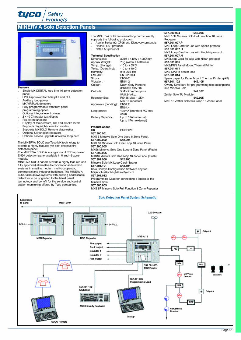
Max 1.2Km
220-240Va.c.
Fire output
Fault output
Sounder 1
Sounder 2
Aux. output
MSR Repeater MSR Repeater
ASCII Qwerty Keyboard
Laptop
557.301.102Keyboard
557.301.012Programming Lead
CIM
MX VirtualDetector
ConventionalDetector
Callpoint
Callpoint
Sounders
557.301.005MSPPrinter
MXS 8/16
Loop backto panel
SOLO Remote
24 Vd.c.24V.d.c.
SNMMIM
PIM
DIN
DIM
Solo Detection Panel System Schematic
23SeptMXCat. qxd 11/10/02 11:42 pm Page 21
Page 22
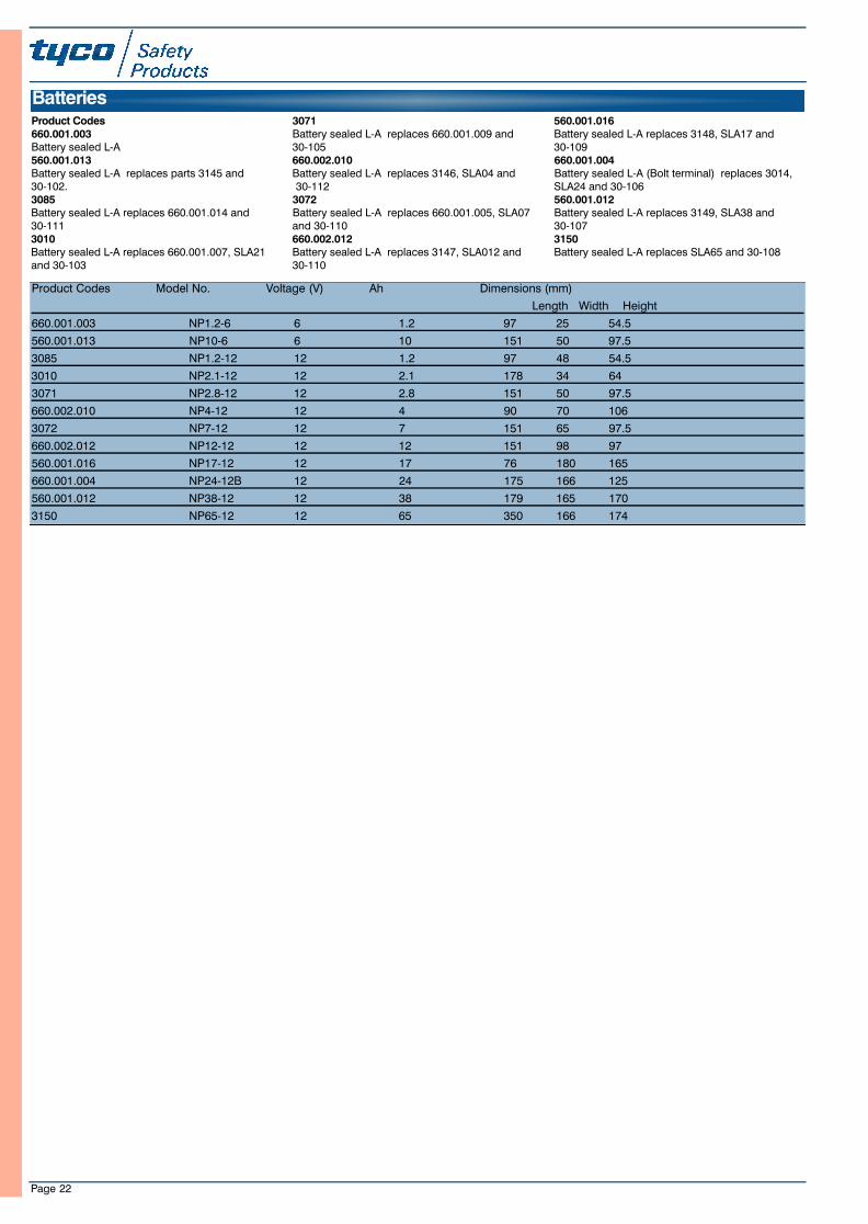
Product Codes Model No. Voltage (V) Ah Dimensions (mm)
Length Width Height
660.001.003 NP1.2-6 6 1.2 97 25 54.5
560.001.013 NP10-6 6 10 151 50 97.5
3085 NP1.2-12 12 1.2 97 48 54.5
3010 NP2.1-12 12 2.1 178 34 64
3071 NP2.8-12 12 2.8 151 50 97.5
660.002.010 NP4-12 12 4 90 70 106
3072 NP7-12 12 7 151 65 97.5
660.002.012 NP12-12 12 12 151 98 97
560.001.016 NP17-12 12 17 76 180 165
660.001.004 NP24-12B 12 24 175 166 125
560.001.012 NP38-12 12 38 179 165 170
3150 NP65-12 12 65 350 166 174
Product Codes660.001.003Battery sealed L-A560.001.013Battery sealed L-A replaces parts 3145 and 30-102.3085Battery sealed L-A replaces 660.001.014 and 30-1113010Battery sealed L-A replaces 660.001.007, SLA21and 30-103
3071Battery sealed L-A replaces 660.001.009 and 30-105660.002.010Battery sealed L-A replaces 3146, SLA04 and30-112
3072Battery sealed L-A replaces 660.001.005, SLA07and 30-110660.002.012Battery sealed L-A replaces 3147, SLA012 and30-110
560.001.016Battery sealed L-A replaces 3148, SLA17 and 30-109660.001.004Battery sealed L-A (Bolt terminal) replaces 3014,SLA24 and 30-106560.001.012Battery sealed L-A replaces 3149, SLA38 and 30-1073150Battery sealed L-A replaces SLA65 and 30-108
Batteries
23SeptMXCat. qxd 11/10/02 11:42 pm Page 22
Page 23
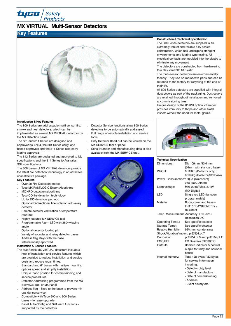
Introduction & Key Features
The 800 Series are addressable multi-sensor fire,
smoke and heat detectors, which can be
implemented as several MX VIRTUAL detectors by
the MX detection panel.
The 801 and 811 Series are designed and
approved to EN54, the 801 Series carry land
based approvals and the 811 Series also carry
Marine approvals.
The 812 Series are designed and approved to UL
specifications and the 814 Series to Australian
SSL specifications.
The 800 Series of MX VIRTUAL detectors provide
the latest fire detection technology in an attractive
cost effective package.
Key Features
. Over 20 Fire Detection modes
. Tyco MX FASTLOGIC Expert Algorithms
. MX HPO detection algorithms
. Tyco CO fire detection technology
. Up to 250 detectors per loop
. Optional bi-directional line isolation with every
detector
. Remote detector verification & temperature
read-out
. Highly featured MX SERVICE tool
. Programmable Alarm LED with 360o viewing
angle
. Optional detector locking pin
. Variety of sounder and relay detector bases
. Address flag stays with the base
. Internationally approved
Installation & Service Features
The 800 Series MX VIRTUAL detectors include a
host of installation and service features which
are provided to reduce installation and service
costs and reduce repair times.
. Standard and 6” bases with multiple mounting
options speed and simplify installation
. Unique ‘park’ position for commissioning and
service procedures.
. Detector Addressing programmed from the MX
SERVICE Tool or MX Panel
. Address flag – fixed to the base to prevent mix
ups during service
. Compatible with Tyco 600 and 900 Series
bases – for easy upgrade
. Panel Auto-Config and Self learn functions –
supported by the detectors
. Detector Service functions allow 800 Series
detectors to be automatically addressed
. Full range of remote installation and service
tools
. Dirty Detector Read-out can be viewed on the
MX SERVICE tool or panel.
. Serial Number and Manufacturing data is also
available from the MX SERVICE tool.
Construction & Technical Specification
The 800 Series detectors are supplied in an
extremely robust and reliable fully sealed
construction, which has undergone stringent
environmental and Marine type testing. All
electrical contacts are moulded into the plastic to
eliminate any movement.
The detectors are constructed from hardwearing
Fire Resistant FR110 plastic.
The multi-sensor detectors are environmentally
friendly. They use no radioactive parts and can be
returned to the factory for recycling at the end of
their life.
All 800 Series detectors are supplied with integral
dust covers as part of the packaging. Dust covers
are retained throughout installation and removed
at commissioning time.
Unique design of the 801PH optical chamber
provides immunity to thrips and other small
insects without the need for metal gauze.
Technical Specification
Dimensions: Dia 109mm /43H mm
(54mm with standard base)
Weight: 0.124kg (Detector only)
0.192kg (Detector/Std Base)
Power Consumption:150µA (Quiescent)
2 to 5mA (Alarm)
Loop voltage: Min. 20.0V/Max. 37.5V
(MX Digital)
LED: Single red LED (function
programmable)
Material: Body, cover and base –
FR110 ”BAYBLEND” Fire
Resistant
Temp. Measurement: Accuracy +/-0.25oC
Resolution 2oC
Operating Temp.: See specific detector
Storage Temp.: See specific detector
Relative Humidity: 95% non-condensing
Shock/Vibration/Impact: prEN54:pt.7
Corrosion: prEN54:pt.5 and prEn54:pt.7
EMC/RFI: EC Directive 89/336/EC
Outputs: Remote indicator & control
output for relay and sounder
bases
Internal memory: Total 128 bytes / 32 bytes
for service information
including:
- Detector dirty level
- Date of manufacture
- Date of commissioning
- Address
- Event history etc.
Key Features
MX VIRTUAL Multi-Sensor Detectors
23SeptMXCat. qxd 11/10/02 11:42 pm Page 23
Page 24
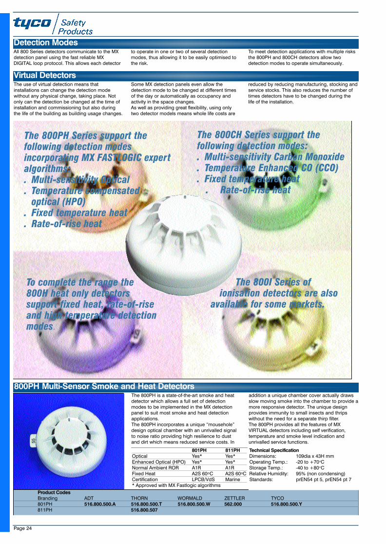
The 800PH is a state-of-the-art smoke and heatdetector which allows a full set of detectionmodes to be implemented in the MX detectionpanel to suit most smoke and heat detectionapplications.The 800PH incorporates a unique “mousehole”design optical chamber with an unrivalled signalto noise ratio providing high resilience to dustand dirt which means reduced service costs. In
addition a unique chamber cover actually drawsslow moving smoke into the chamber to provide amore responsive detector. The unique designprovides immunity to small insects and thripswithout the need for a separate thirp filter.The 800PH provides all the features of MXVIRTUAL detectors including self verification,temperature and smoke level indication andunrivalled service functions.
800PH Multi-Sensor Smoke and Heat Detectors
801PH 811PHOptical Yes* Yes*Enhanced Optical (HPO) Yes* Yes*Normal Ambient ROR A1R A1RFixed Heat A2S 60oC A2S 60oCCertification LPCB/VdS Marine* Approved with MX Fastlogic algorithms
Product CodesBranding ADT THORN WORMALD ZETTLER TYCO801PH 516.800.500.A 516.800.500.T 516.800.500.W 562.000 516.800.500.Y811PH 516.800.507
Technical SpecificationDimensions: 109dia x 43H mmOperating Temp.: -20 to +70oCStorage Temp.: -40 to +80oCRelative Humidity: 95% (non condensing)Standards: prEN54 pt 5, prEN54 pt 7
Virtual DetectorsThe use of virtual detection means thatinstallations can change the detection modewithout any physical change, taking place. Notonly can the detection be changed at the time ofinstallation and commissioning but also duringthe life of the building as building usage changes.
Some MX detection panels even allow thedetection mode to be changed at different timesof the day or automatically as occupancy andactivity in the space changes.As well as providing great flexibility, using onlytwo detector models means whole life costs are
reduced by reducing manufacturing, stocking andservice stocks. This also reduces the number oftimes detectors have to be changed during thelife of the installation.
Detection ModesAll 800 Series detectors communicate to the MXdetection panel using the fast reliable MXDIGITAL loop protocol. This allows each detector
to operate in one or two of several detectionmodes, thus allowing it to be easily optimised tothe risk.
To meet detection applications with multiple risksthe 800PH and 800CH detectors allow twodetection modes to operate simultaneously.
The 800I Series ofionisation detectors are also
available for some markets.
The 800PH Series support thefollowing detection modesincorporating MX FASTLOGIC expertalgorithms:. Multi-sensitivity Optical . Temperature compensated
optical (HPO) . Fixed temperature heat. Rate-of-rise heat
To complete the range the800H heat only detectorssupport fixed heat, rate-of-riseand high temperature detectionmodes.
The 800CH Series support thefollowing detection modes:. Multi-sensitivity Carbon Monoxide. Temperature Enhanced CO (CCO). Fixed temperature heat
. Rate-of-rise heat
23SeptMXCat. qxd 11/10/02 11:43 pm Page 24
Page 25
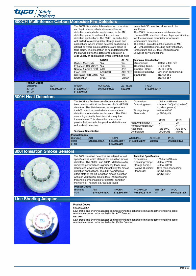
The 800H is a flexible cost-effective addressableheat detector with all the features of MX VIRTUALdetectors. The 800H returns the temperature tothe MX detection panel which allows variousdetection modes to be implemented. The 800Huses a high quality thermistor with very lowthermal mass. This allows the detectors toprovide fast accurate temperature detection aswell as heat detection.
Technical Specification
Dimensions: 109dia x 43H mmOperating temp.: -25 to +70oC(-40 to +90oC
for short periods)Storage temp.: -40 to +80oCStandards: prEN54:pt.5
800H Heat Detectors
801H 811HHigh Ambient ROR CR CRNormal Ambient ROR A1R A1RFixed Heat A2S 60oC A2S 60oCCertification LPCB/VdS Marine
Product CodesBranding ADT THORN WORMALD ZETTLER TYCO801H 516.800.502.A 516.800.502.T 516.800.502.W 562.002 516.800.502.Y811H 516.800.509
The 800I ionisation detectors are offered for oldspecifications which still call for ionisation smokedetectors. The 800CH and 800PH detectors offerimproved performance, significantly lower falsealarms and environmental compatibility for smokedetection applications. The 800I neverthelessoffers state-of-the-art ionisation smoke detectionwith self verification, smoke level indication andthreshold compensation for detector conditionmonitoring. The 801I is LPCB approved.
Technical SpecificationDimensions: 109dia x 43H mmOperating Temp.: -20 to +70oCStorage Temp.: -40 to +80oCRelative Humidity: 95% (non condensing)Standards: prEN54 pt 5
prEN54 pt 7
800I Ionisation Smoke Sensors
Product CodesBranding ADT THORN WORMALD ZETTLER TYCO801I 516.800.515.A 516.800.515.T 516.800.515.W NA 516.800.515.Y
The 800CH is a state-of-the-art carbon monoxideand heat detector which allows a full set ofdetection modes to be implemented in the MXdetection panel to suit most fire and heatdetection applications. The 800CH is particularlywell suited to sleeping risks, storage areas andapplications where smoke detector positioning isdifficult or where smoke detectors are prone tofalse alarm. The integration of heat detection intothe 800CH allows the detector to operate in awide variety of applications where combined risks
mean that CO detection alone would beinsufficient.The 800CH incorporates a reliable electro-chemical CO detection cell and high specificationlow thermal mass thermistor for accuratetemperature detection.The 800CH provides all the features of MXVIRTUAL detectors including self verification,temperature and CO level indication andunrivalled service functions.
800CH Multi-Sensor Carbon Monoxide Fire Detectors
801CH 811CHCarbon Monoxide Yes YesEnhanced CO (CCO) Yes YesNormal Ambient ROR A1R A1RFixed Heat A2S 60oC A2S 60oCCCO plus ROR (A1R) Yes YesCertification LPCB Marine
Product CodesBranding ADT THORN WORMALD ZETTLER TYCO801CH 516.800.501.A 516.800.501.T 516.800.501.W 562.001 516.800.501.Y811CH 516.800.508
Technical SpecificationDimensions: 109dia x 43H mmOperating Temp.: 0 to +55oCStorage Temp.: -20 to +55oCRelative Humidity: 95% (non condensing)Standards: prEN54 pt 5
prEN54 pt 7
Line Shorting AdaptorProduct Codes517.050.002.ALow profile line shorting adaptor commissioning tool (shorts terminals together enabling cableresistance checks to be carried out) - ADT Branded562.004Low profile line shorting adaptor commissioning tool (shorts terminals together enabling cableresistance checks to be carried out) - Zettler Branded
23SeptMXCat. qxd 11/10/02 11:43 pm Page 25
Page 26
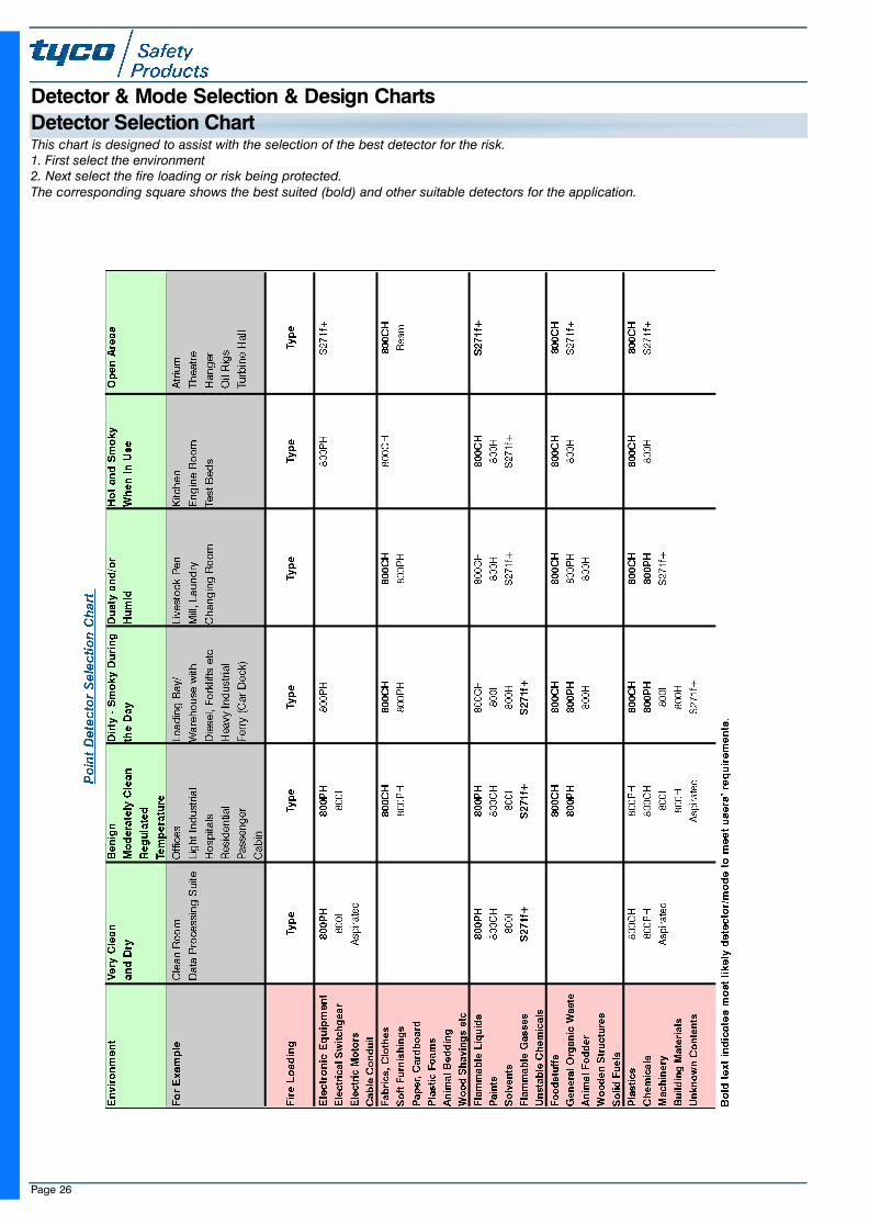
This chart is designed to assist with the selection of the best detector for the risk.1. First select the environment2. Next select the fire loading or risk being protected.The corresponding square shows the best suited (bold) and other suitable detectors for the application.
Detector & Mode Selection & Design ChartsDetector Selection Chart
23SeptMXCat. qxd 11/10/02 11:43 pm Page 26
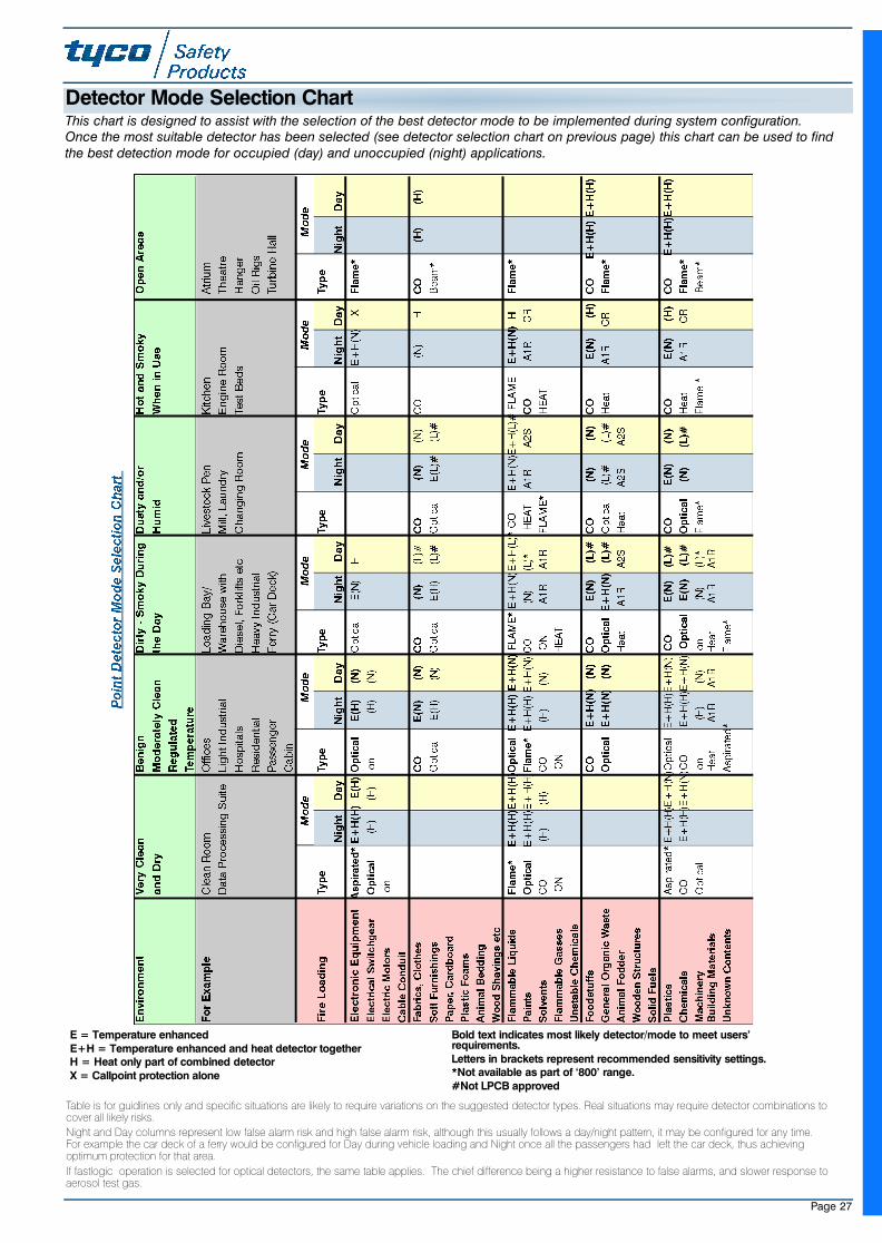
Page 27
E = Temperature enhanced E+H = Temperature enhanced and heat detector togetherH = Heat only part of combined detectorX = Callpoint protection alone
Bold text indicates most likely detector/mode to meet users’requirements.Letters in brackets represent recommended sensitivity settings.*Not available as part of ‘800’ range.#Not LPCB approved
This chart is designed to assist with the selection of the best detector mode to be implemented during system configuration.Once the most suitable detector has been selected (see detector selection chart on previous page) this chart can be used to findthe best detection mode for occupied (day) and unoccupied (night) applications.
Detector Mode Selection Chart
Table is for guidlines only and specific situations are likely to require variations on the suggested detector types. Real situations may require detector combinations tocover all likely risks.
Night and Day columns represent low false alarm risk and high false alarm risk, although this usually follows a day/night pattern, it may be configured for any time.For example the car deck of a ferry would be configured for Day during vehicle loading and Night once all the passengers had left the car deck, thus achievingoptimum protection for that area.
If fastlogic operation is selected for optical detectors, the same table applies. The chief difference being a higher resistance to false alarms, and slower response toaerosol test gas.
23SeptMXCat. qxd 11/10/02 11:43 pm Page 27
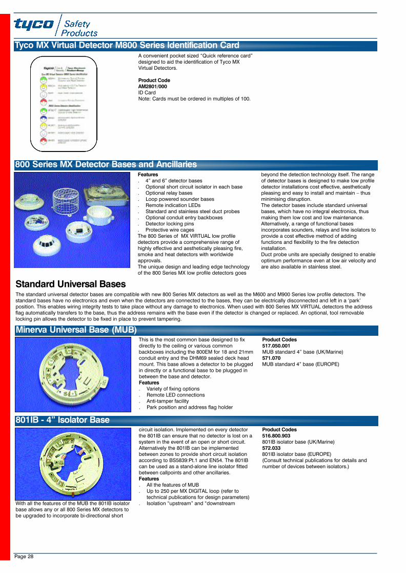
Page 28
A convenient pocket sized “Quick reference card”designed to aid the identification of Tyco MXVirtual Detectors.
Product CodeAM2801/000ID CardNote: Cards must be ordered in multiples of 100.
Features. 4” and 6” detector bases. Optional short circuit isolator in each base. Optional relay bases . Loop powered sounder bases. Remote indication LEDs. Standard and stainless steel duct probes . Optional conduit entry backboxes. Detector locking pins. Protective wire cagesThe 800 Series of MX VIRTUAL low profiledetectors provide a comprehensive range ofhighly effective and aesthetically pleasing fire,smoke and heat detectors with worldwideapprovals.The unique design and leading edge technologyof the 800 Series MX low profile detectors goes
beyond the detection technology itself. The rangeof detector bases is designed to make low profiledetector installations cost effective, aestheticallypleasing and easy to install and maintain – thusminimising disruption.The detector bases include standard universalbases, which have no integral electronics, thusmaking them low cost and low maintenance.Alternatively, a range of functional basesincorporates sounders, relays and line isolators toprovide a cost effective method of addingfunctions and flexibility to the fire detectioninstallation.Duct probe units are specially designed to enableoptimum performance even at low air velocity andare also available in stainless steel.
With all the features of the MUB the 801IB isolatorbase allows any or all 800 Series MX detectors tobe upgraded to incorporate bi-directional short
circuit isolation. Implemented on every detectorthe 801IB can ensure that no detector is lost on asystem in the event of an open or short circuit.Alternatively the 801IB can be implementedbetween zones to provide short circuit isolationaccording to BS5839:Pt.1 and EN54. The 801IBcan be used as a stand-alone line isolator fittedbetween callpoints and other ancillaries.Features. All the features of MUB. Up to 250 per MX DIGITAL loop (refer to
technical publications for design parameters). Isolation “upstream” and “downstream
Product Codes516.800.903801IB isolator base (UK/Marine)572.033801IB isolator base (EUROPE)(Consult technical publications for details andnumber of devices between isolators.)
800 Series MX Detector Bases and Ancillaries
801IB - 4” Isolator Base
The standard universal detector bases are compatible with new 800 Series MX detectors as well as the M600 and M900 Series low profile detectors. Thestandard bases have no electronics and even when the detectors are connected to the bases, they can be electrically disconnected and left in a ‘park’position. This enables wiring integrity tests to take place without any damage to electronics. When used with 800 Series MX VIRTUAL detectors the addressflag automatically transfers to the base, thus the address remains with the base even if the detector is changed or replaced. An optional, tool removablelocking pin allows the detector to be fixed in place to prevent tampering.
This is the most common base designed to fixdirectly to the ceiling or various commonbackboxes including the 800EM for 18 and 21mmconduit entry and the DHM69 sealed deck headmount. This base allows a detector to be pluggedin directly or a functional base to be plugged inbetween the base and detector.Features. Variety of fixing options. Remote LED connections. Anti-tamper facility. Park position and address flag holder
Product Codes517.050.001MUB standard 4” base (UK/Marine) 571.070MUB standard 4” base (EUROPE)
Minerva Universal Base (MUB)
Standard Universal Bases
Tyco MX Virtual Detector M800 Series Identification Card
23SeptMXCat. qxd 11/10/02 11:43 pm Page 28
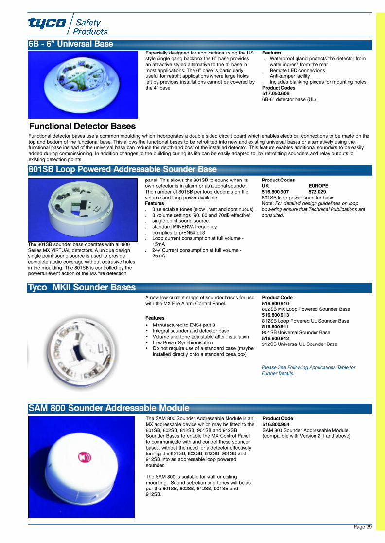
The SAM 800 Sounder Addressable Module is anMX addressable device which may be fitted to the801SB, 802SB, 812SB, 901SB and 912SBSounder Bases to enable the MX Control Panelto communicate with and control these sounderbases, without the need for a detector effectivelyturning the 801SB, 802SB, 812SB, 901SB and912SB into an addressable loop poweredsounder.
The SAM 800 is suitable for wall or ceilingmounting. Sound selection and tones will be asper the 801SB, 802SB, 812SB, 901SB and912SB.
Product Code 516.800.954SAM 800 Sounder Addressable Module(compatible with Version 2.1 and above)
Page 29
The 801SB sounder base operates with all 800Series MX VIRTUAL detectors. A unique designsingle point sound source is used to providecomplete audio coverage without obtrusive holesin the moulding. The 801SB is controlled by thepowerful event action of the MX fire detection
panel. This allows the 801SB to sound when itsown detector is in alarm or as a zonal sounder.The number of 801SB per loop depends on thevolume and loop power available. Features. 3 selectable tones (slow , fast and continuous). 3 volume settings (90, 80 and 70dB effective). single point sound source. standard MINERVA frequency. complies to prEN54:pt.3. Loop current consumption at full volume -
15mA. 24V Current consumption at full volume -
25mA
Product CodesUK EUROPE516.800.907 572.029801SB loop power sounder baseNote: For detailed design guidelines on looppowering ensure that Technical Publications areconsulted.
801SB Loop Powered Addressable Sounder Base
Functional detector bases use a common moulding which incorporates a double sided circuit board which enables electrical connections to be made on thetop and bottom of the functional base. This allows the functional bases to be retrofitted into new and existing universal bases or alternatively using thefunctional base instead of the universal base can reduce the depth and cost of the installed detector. This feature enables additional sounders to be easilyadded during commissioning. In addition changes to the building during its life can be easily adapted to, by retrofitting sounders and relay outputs toexisting detection points.
Functional Detector Bases
Especially designed for applications using the USstyle single gang backbox the 6” base providesan attractive styled alternative to the 4” base inmost applications. The 6” base is particularlyuseful for retrofit applications where large holesleft by previous installations cannot be covered bythe 4” base.
Features. Waterproof gland protects the detector from
water ingress from the rear. Remote LED connections. Anti-tamper facility. Includes blanking pieces for mounting holesProduct Codes517.050.6066B-6” detector base (UL)
6B - 6” Universal Base
A new low current range of sounder bases for usewith the MX Fire Alarm Control Panel.
Features
• Manufactured to EN54 part 3• Integral sounder and detector base• Volume and tone adjustable after installation• Low Power Synchronisation• Do not require use of a standard base (maybe
installed directly onto a standard besa box)
Product Code516.800.910802SB MX Loop Powered Sounder Base516.800.913812SB Loop Powered UL Sounder Base516.800.911901SB Universal Sounder Base516.800.912912SB Universal UL Sounder Base
Please See Following Applications Table forFurther Details.
Tyco MKII Sounder Bases
SAM 800 Sounder Addressable Module
23SeptMXCat. qxd 11/10/02 11:43 pm Page 29
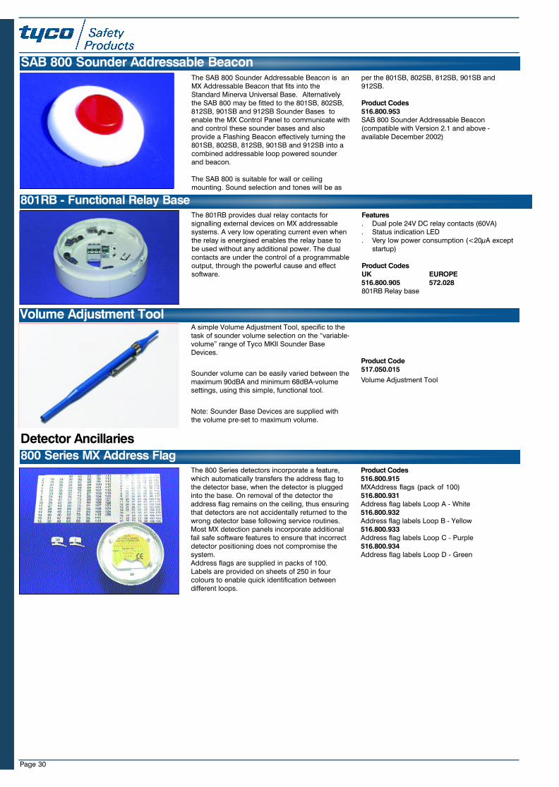
Page 30
The 800 Series detectors incorporate a feature,which automatically transfers the address flag tothe detector base, when the detector is pluggedinto the base. On removal of the detector theaddress flag remains on the ceiling, thus ensuringthat detectors are not accidentally returned to thewrong detector base following service routines.Most MX detection panels incorporate additionalfail safe software features to ensure that incorrectdetector positioning does not compromise thesystem.Address flags are supplied in packs of 100.Labels are provided on sheets of 250 in fourcolours to enable quick identification betweendifferent loops.
Product Codes516.800.915MXAddress flags (pack of 100)516.800.931Address flag labels Loop A - White516.800.932Address flag labels Loop B - Yellow516.800.933Address flag labels Loop C - Purple516.800.934Address flag labels Loop D - Green
800 Series MX Address Flag
Detector Ancillaries
A simple Volume Adjustment Tool, specific to thetask of sounder volume selection on the “variable-volume” range of Tyco MKII Sounder BaseDevices.
Sounder volume can be easily varied between themaximum 90dBA and minimum 68dBA-volumesettings, using this simple, functional tool.
Note: Sounder Base Devices are supplied withthe volume pre-set to maximum volume.
Product Code517.050.015
Volume Adjustment Tool
Volume Adjustment Tool
The 801RB provides dual relay contacts forsignalling external devices on MX addressablesystems. A very low operating current even whenthe relay is energised enables the relay base tobe used without any additional power. The dualcontacts are under the control of a programmableoutput, through the powerful cause and effectsoftware.
Features. Dual pole 24V DC relay contacts (60VA). Status indication LED. Very low power consumption (<20µA except
startup)
Product CodesUK EUROPE516.800.905 572.028801RB Relay base
801RB - Functional Relay Base
The SAB 800 Sounder Addressable Beacon is anMX Addressable Beacon that fits into theStandard Minerva Universal Base. Alternativelythe SAB 800 may be fitted to the 801SB, 802SB,812SB, 901SB and 912SB Sounder Bases toenable the MX Control Panel to communicate withand control these sounder bases and alsoprovide a Flashing Beacon effectively turning the801SB, 802SB, 812SB, 901SB and 912SB into acombined addressable loop powered sounderand beacon.
The SAB 800 is suitable for wall or ceilingmounting. Sound selection and tones will be as
per the 801SB, 802SB, 812SB, 901SB and912SB.
Product Codes516.800.953SAB 800 Sounder Addressable Beacon(compatible with Version 2.1 and above -available December 2002)
SAB 800 Sounder Addressable Beacon
23SeptMXCat. qxd 11/10/02 11:43 pm Page 30
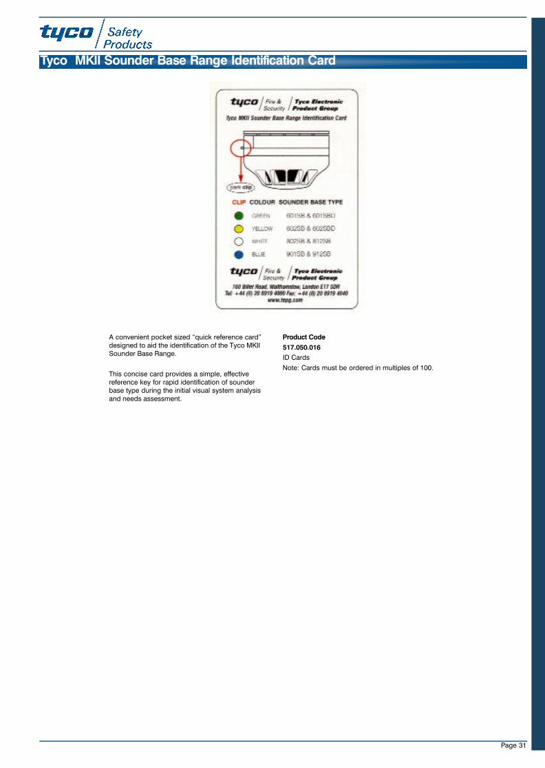
Page 31
Tyco MKII Sounder Base Range Identification Card
A convenient pocket sized “quick reference card”designed to aid the identification of the Tyco MKIISounder Base Range.
This concise card provides a simple, effectivereference key for rapid identification of sounderbase type during the initial visual system analysisand needs assessment.
Product Code
517.050.016
ID Cards
Note: Cards must be ordered in multiples of 100.
23SeptMXCat. qxd 11/10/02 11:43 pm Page 31
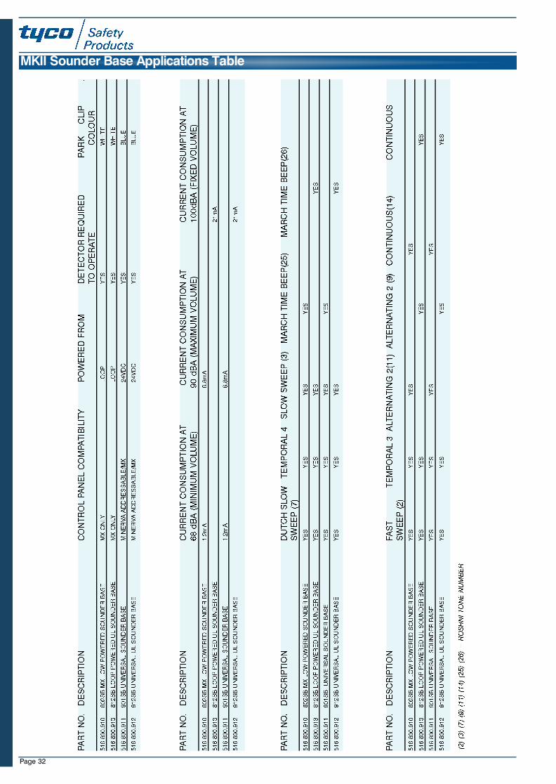
Page 32
MKII Sounder Base Applications Table
23SeptMXCat. qxd 11/10/02 11:43 pm Page 32
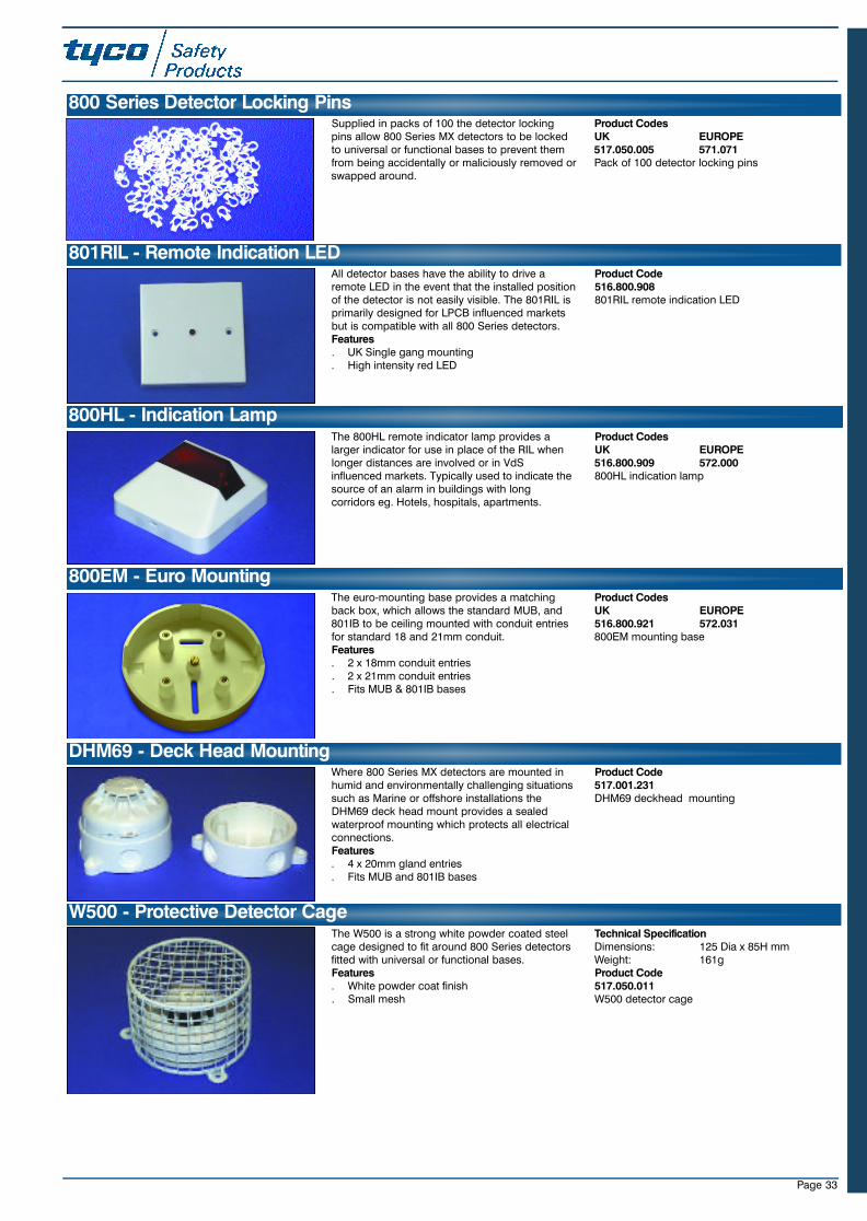
Page 33
Supplied in packs of 100 the detector lockingpins allow 800 Series MX detectors to be lockedto universal or functional bases to prevent themfrom being accidentally or maliciously removed orswapped around.
Product CodesUK EUROPE517.050.005 571.071Pack of 100 detector locking pins
800 Series Detector Locking Pins
All detector bases have the ability to drive aremote LED in the event that the installed positionof the detector is not easily visible. The 801RIL isprimarily designed for LPCB influenced marketsbut is compatible with all 800 Series detectors.Features. UK Single gang mounting. High intensity red LED
Product Code516.800.908801RIL remote indication LED
801RIL - Remote Indication LED
The 800HL remote indicator lamp provides alarger indicator for use in place of the RIL whenlonger distances are involved or in VdSinfluenced markets. Typically used to indicate thesource of an alarm in buildings with longcorridors eg. Hotels, hospitals, apartments.
Product CodesUK EUROPE516.800.909 572.000800HL indication lamp
800HL - Indication Lamp
The euro-mounting base provides a matchingback box, which allows the standard MUB, and801IB to be ceiling mounted with conduit entriesfor standard 18 and 21mm conduit.Features. 2 x 18mm conduit entries. 2 x 21mm conduit entries. Fits MUB & 801IB bases
Product CodesUK EUROPE516.800.921 572.031800EM mounting base
Where 800 Series MX detectors are mounted inhumid and environmentally challenging situationssuch as Marine or offshore installations theDHM69 deck head mount provides a sealedwaterproof mounting which protects all electricalconnections. Features. 4 x 20mm gland entries. Fits MUB and 801IB bases
Product Code517.001.231DHM69 deckhead mounting
800EM - Euro Mounting
DHM69 - Deck Head Mounting
The W500 is a strong white powder coated steelcage designed to fit around 800 Series detectorsfitted with universal or functional bases.Features. White powder coat finish. Small mesh
Technical SpecificationDimensions: 125 Dia x 85H mmWeight: 161gProduct Code517.050.011W500 detector cage
W500 - Protective Detector Cage
23SeptMXCat. qxd 11/10/02 11:43 pm Page 33
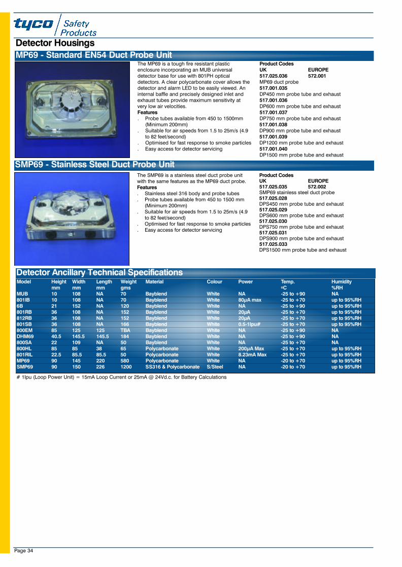
Page 34
The SMP69 is a stainless steel duct probe unitwith the same features as the MP69 duct probe.Features. Stainless steel 316 body and probe tubes. Probe tubes available from 450 to 1500 mm
(Minimum 200mm). Suitable for air speeds from 1.5 to 25m/s (4.9
to 82 feet/second). Optimised for fast response to smoke particles. Easy access for detector servicing
Product CodesUK EUROPE517.025.035 572.002SMP69 stainless steel duct probe517.025.028DPS450 mm probe tube and exhaust517.025.029DPS600 mm probe tube and exhaust517.025.030DPS750 mm probe tube and exhaust517.025.031DPS900 mm probe tube and exhaust517.025.033DPS1500 mm probe tube and exhaust
Model Height Width Length Weight Material Colour Power Temp. Humiditymm mm mm gms oC %RH
MUB 10 108 NA 70 Bayblend White NA -25 to +90 NA801IB 10 108 NA 70 Bayblend White 80µA max -25 to +70 up to 95%RH6B 21 152 NA 120 Bayblend White NA -25 to +90 up to 95%RH801RB 36 108 NA 152 Bayblend White 20µA -25 to +70 up to 95%RH812RB 36 108 NA 152 Bayblend White 20µA -25 to +70 up to 95%RH801SB 36 108 NA 166 Bayblend White 0.5-1lpu# -25 to +70 up to 95%RH800EM 85 125 125 TBA Bayblend White NA -25 to +90 NADHM69 40.5 145.5 145.5 184 Bayblend White NA -25 to +90 NA800SA 22 109 NA 50 Bayblend White NA -25 to +70 NA800HL 85 85 38 65 Polycarbonate White 200µA Max -25 to +70 up to 95%RH801RIL 22.5 85.5 85.5 50 Polycarbonate White 8.23mA Max -25 to +70 up to 95%RHMP69 90 145 220 580 Polycarbonate White NA -20 to +70 up to 95%RHSMP69 90 150 226 1200 SS316 & Polycarbonate S/Steel NA -20 to +70 up to 95%RH
SMP69 - Stainless Steel Duct Probe Unit
Detector Ancillary Technical Specifications
The MP69 is a tough fire resistant plasticenclosure incorporating an MUB universaldetector base for use with 801PH opticaldetectors. A clear polycarbonate cover allows thedetector and alarm LED to be easily viewed. Aninternal baffle and precisely designed inlet andexhaust tubes provide maximum sensitivity atvery low air velocities.Features. Probe tubes available from 450 to 1500mm
(Minimum 200mm). Suitable for air speeds from 1.5 to 25m/s (4.9
to 82 feet/second). Optimised for fast response to smoke particles. Easy access for detector servicing
Product CodesUK EUROPE517.025.036 572.001MP69 duct probe517.001.035DP450 mm probe tube and exhaust517.001.036DP600 mm probe tube and exhaust517.001.037DP750 mm probe tube and exhaust517.001.038DP900 mm probe tube and exhaust517.001.039DP1200 mm probe tube and exhaust517.001.040DP1500 mm probe tube and exhaust
MP69 - Standard EN54 Duct Probe Unit
Detector Housings
# 1lpu (Loop Power Unit) = 15mA Loop Current or 25mA @ 24Vd.c. for Battery Calculations
23SeptMXCat. qxd 11/10/02 11:43 pm Page 34
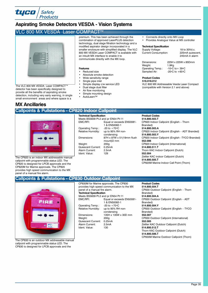
Page 35
The CP820 is an indoor MX addressable manualcallpoint with programmable status LED. TheCP820 is designed for LPCB approvals and theCP820M for Marine approvals. The CP820provides high speed communication to the MXpanel of a manual fire alarm.
Technical SpecificationMeets BS5839 Pt.2 and pr EN54 Pt:11 EMC/RFI: Equal or exceeds EN50081-
1 & EN50082-1Operating Temp.: -20 to +70oCRelative Humidity: up to 95% RH non-
condensingDimensions: 87H x 87W x 51(19mm flush
mount)D mm Weight: 200gQuiescent Current: 0.25mAAlarm Current: 2.5mAIdent. Value: 129
Product Codes514.800.503.TCP820 Indoor Callpoint (English – ThornBranded)514.800.503.ACP820 Indoor Callpoint (English – ADT Branded)514.800.503.YCP820 Indoor Callpoint (English –TYCO Branded)552.006CP820 Indoor Callpoint (International)514.800.511.TThorn KAC Indoor Callpoint (Dutch)552.004Zettler KAC indoor Callpoint (Dutch)514.800.505.TCP820M Marine Indoor Call Point (Thorn)
Callpoints & Pullstations - CP820 Indoor CallpointMX Ancillaries
The CP830 is an outdoor MX addressable manualcallpoint with programmable status LED. TheCP830 is designed for LPCB approvals and the
CP830M for Marine approvals. The CP830provides high speed communication to the MXpanel of a manual fire alarm. Technical SpecificationMeets BS5839 Pt.2 and pr EN54 Pt:11 EMC/RFI: Equal or exceeds EN50081-
1 & EN50082-1Operating Temp.: -20 to +70oCRelative Humidity: up to 95% RH non-
condensingDimensions: 135H x 135W x 30D mm Weight: 200gQuiescent Current: 0.25mAAlarm Current: 2.5mAIdent. Value: 130
Product Codes514.800.504.TCP830 Outdoor Callpoint (English – ThornBranded)514.800.504.ACP830 Outdoor Callpoint (English – ADTBranded)514.800.504.YCP830 Outdoor Callpoint (English – TYCOBranded)552.007CP830 Outdoor Callpoint (International)552.005Zettler KAC Outdoor Callpoint (Dutch)514.800.512.TThorn KAC Outdoor Callpoint (Dutch)514.800.506.TCP830M Marine Outdoor Callpoint (Thorn)
Callpoints & Pullstations - CP830 Outdoor Callpoint
Aspirating Smoke Detectors VESDA - Vision Systems
VLC 800 MX VESDA Laser COMPACTTM
The VLC 800 MX VESDA Laser COMPACT TM
detector has been specifically designed toprovide all the benefits of aspirating smokedetection, including very early warning, in singlesmall environment areas and where space is a
premium. This has been achieved through thecombination of approved LaserPLUS detectiontechnology, dual stage filtration technology and amodified aspirator design incorporated in asmaller enclosure with simplified display. The VLC800 MX VESDA Laser COMPACT is available withan inbuilt MX interface to enable it tocommunicate directly with the MX loop.
Features• Reduced size• Absolute smoke detection• Wide sensitivity range• Single pipe inlet• Simple display c/w service LED• Dual stage dust filter • Air flow monitoring• Simple mounting design• AutoLearnTM
• Connects directly onto MX Loop• Provides Analogue Value at MX controller
Technical SpecificationSupply Voltage: 18 to 30Vd.c.Current Consumption: 225mA quiescent,
245mA in alarm
Dimensions: 225H x 225W x 85DmmWeight: 1.9KgOperating Temp.: -10oC to+ 39oCSampled Air: -20oC to +60oC
Product Codes516.018.012VLC 800 MX Addressable Vesda Laser Compact(compatible with Version 2.1 and above)
23SeptMXCat. qxd 11/10/02 11:44 pm Page 35
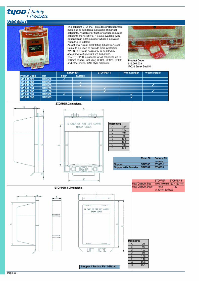
Page 36
The callpoint STOPPER provides protection frommalicious or accidental activation of manualcallpoints. Available for flush or surface mountedcallpoints the ‘STOPPER’ is also available withoptional high pitch sounder which is activatedwhen the lid is lifted.An optional ‘Break-Seal’ fitting kit allows ‘Break-Seals’ to be used to provide extra protection.WARNING:-Break seals only to be fitted byagreement with relevant fire authorities.The STOPPER is suitable for all callpoints up to100mm square, including CP820, CP920, CP200and other indoor KAC style callpoints.
Product Code515.001.033IPO36 Break Seal Kit
STOPPER
STOPPER STOPPER II With Sounder WeatherproofProduct Code Ref Flush Surface515.001.029 STI6530515.001.030 STI6531515.001.036 STI6535515.001.034 STI1230515.001.035 STI3150515.001.031 STI6532515.001.032 STI6533 4 4
MillimetresA 137B 140C 104D 45E 12.5F 12.5G 185H 12.5
STOPPER Dimensions
Flush Fit Surface Fit(+30mm)
Stopper STI6530 STI6531Stopper with Sounder STI6532 STI6533
MillimetresA 70B 16C 197D 50E 178F 146G 228H 254
STOPPER II Dimensions
Stopper II Surface Fit - STI1230
S T O P P E R STOPPER IIMax. Callpoint Size 100 x 100mm 160 x 160 mmMax. Callpoint Depth 57.5 1 2 0
(+30mm Surface)
23SeptMXCat. qxd 11/10/02 11:44 pm Page 36
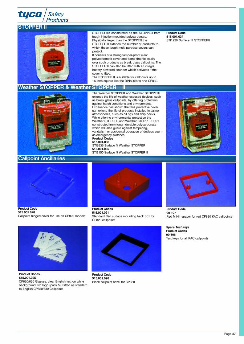
Page 37
STOPPERIIis constructed as the STOPPER fromtough injection moulded polycarbonate.Physically larger than the STOPPER theSTOPPER II extends the number of products towhich these tough multi-purpose covers canprotect.It consists of a strong tamper-proof clearpolycarbonate cover and frame that fits easilyover such products as break glass callpoints. TheSTOPPER II can also be fitted with an integralbattery powered sounder which activates if thecover is lifted.The STOPPER II is suitable for callpoints up to160mm square like the DIN820/830 and CP830.
Product Code515.001.034STI1230 Surface fit STOPPERII
STOPPER II
The Weather STOPPER and Weather STOPPERIIextends the life of weather exposed devices, suchas break glass callpoints, by offering protectionagainst harsh conditions and environments.Experience has shown that this protective covercan extend the life of products installed in salineatmospheres, such as oil rigs and ship decks.While offering environmental protection theWeather STOPPER and Weather STOPPER IIareconstructed from tough durable polycarbonatewhich will also guard against tampering,vandalism or accidental operation of devices suchas emergency switches.Product Codes515.001.036STI6535 Surface fit Weather STOPPER515.001.035STI3150 Surface fit Weather STOPPER II
Weather STOPPER & Weather STOPPER II
Product Codes515.001.025CP820/830 Glasses, clear English text on whitebackground. No logo (pack 5). Fitted as standardto English CP820/830 Callpoints
Callpoint Ancillaries
Spare Test KeysProduct Codes90-106Test keys for all KAC callpoints
Product Code515.001.026Black callpoint bezel for CP820
Product Code515.001.028Callpoint hinged cover for use on CP820 models
Product Code90-107Red M141 spacer for red CP820 KAC callpoints
Product Codes515.001.021Standard Red surface mounting back box forCP820 callpoints
23SeptMXCat. qxd 11/10/02 11:44 pm Page 37
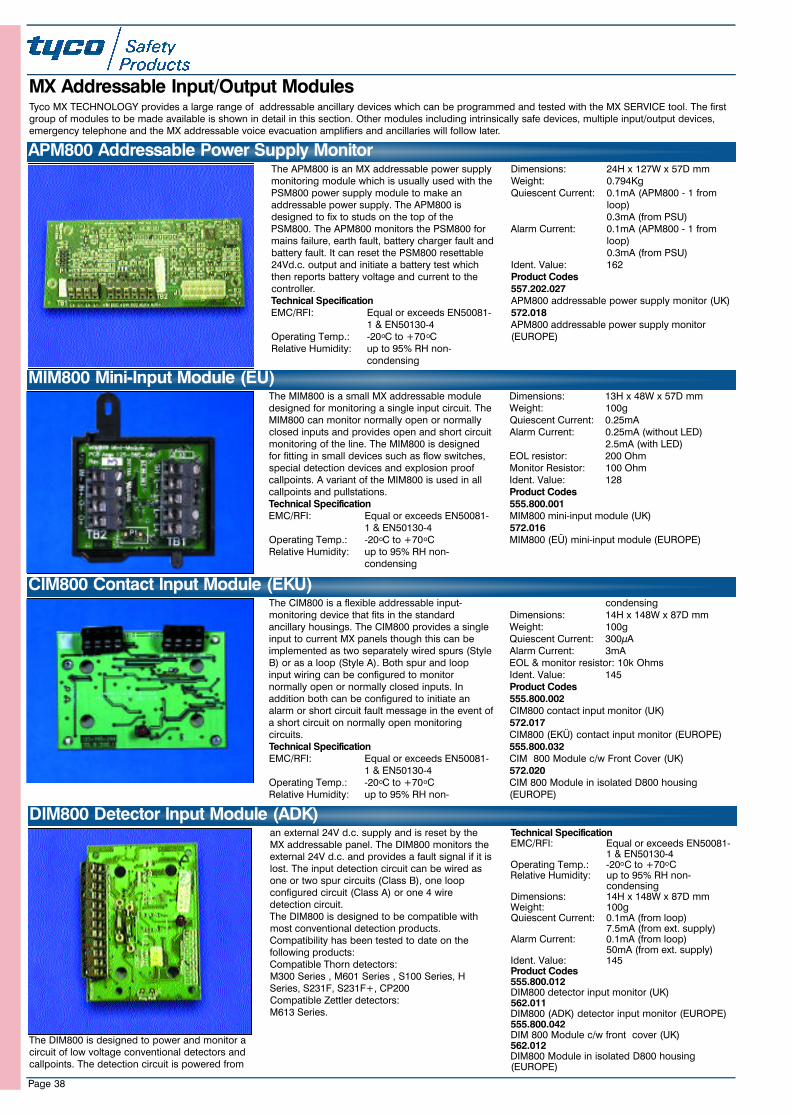
Page 38
The APM800 is an MX addressable power supplymonitoring module which is usually used with thePSM800 power supply module to make anaddressable power supply. The APM800 isdesigned to fix to studs on the top of thePSM800. The APM800 monitors the PSM800 formains failure, earth fault, battery charger fault andbattery fault. It can reset the PSM800 resettable24Vd.c. output and initiate a battery test whichthen reports battery voltage and current to thecontroller.Technical SpecificationEMC/RFI: Equal or exceeds EN50081-
1 & EN50130-4Operating Temp.: -20oC to +70oCRelative Humidity: up to 95% RH non-
condensing
Dimensions: 24H x 127W x 57D mm Weight: 0.794KgQuiescent Current: 0.1mA (APM800 - 1 from
loop)0.3mA (from PSU)
Alarm Current: 0.1mA (APM800 - 1 from loop)0.3mA (from PSU)
Ident. Value: 162Product Codes557.202.027APM800 addressable power supply monitor (UK)572.018APM800 addressable power supply monitor(EUROPE)
APM800 Addressable Power Supply Monitor
MX Addressable Input/Output ModulesTyco MX TECHNOLOGY provides a large range of addressable ancillary devices which can be programmed and tested with the MX SERVICE tool. The firstgroup of modules to be made available is shown in detail in this section. Other modules including intrinsically safe devices, multiple input/output devices,emergency telephone and the MX addressable voice evacuation amplifiers and ancillaries will follow later.
The MIM800 is a small MX addressable moduledesigned for monitoring a single input circuit. TheMIM800 can monitor normally open or normallyclosed inputs and provides open and short circuitmonitoring of the line. The MIM800 is designedfor fitting in small devices such as flow switches,special detection devices and explosion proofcallpoints. A variant of the MIM800 is used in allcallpoints and pullstations. Technical SpecificationEMC/RFI: Equal or exceeds EN50081-
1 & EN50130-4Operating Temp.: -20oC to +70oCRelative Humidity: up to 95% RH non-
condensing
Dimensions: 13H x 48W x 57D mm Weight: 100gQuiescent Current: 0.25mAAlarm Current: 0.25mA (without LED)
2.5mA (with LED)EOL resistor: 200 OhmMonitor Resistor: 100 OhmIdent. Value: 128Product Codes 555.800.001MIM800 mini-input module (UK)572.016MIM800 (EÜ) mini-input module (EUROPE)
MIM800 Mini-Input Module (EÜ)
The CIM800 is a flexible addressable input-monitoring device that fits in the standardancillary housings. The CIM800 provides a singleinput to current MX panels though this can beimplemented as two separately wired spurs (StyleB) or as a loop (Style A). Both spur and loopinput wiring can be configured to monitornormally open or normally closed inputs. Inaddition both can be configured to initiate analarm or short circuit fault message in the event ofa short circuit on normally open monitoringcircuits.Technical SpecificationEMC/RFI: Equal or exceeds EN50081-
1 & EN50130-4Operating Temp.: -20oC to +70oCRelative Humidity: up to 95% RH non-
condensingDimensions: 14H x 148W x 87D mm Weight: 100gQuiescent Current: 300µAAlarm Current: 3mAEOL & monitor resistor: 10k OhmsIdent. Value: 145Product Codes555.800.002CIM800 contact input monitor (UK)572.017CIM800 (EKÜ) contact input monitor (EUROPE)555.800.032CIM 800 Module c/w Front Cover (UK)572.020CIM 800 Module in isolated D800 housing(EUROPE)
CIM800 Contact Input Module (EKÜ)
The DIM800 is designed to power and monitor acircuit of low voltage conventional detectors andcallpoints. The detection circuit is powered from
an external 24V d.c. supply and is reset by theMX addressable panel. The DIM800 monitors theexternal 24V d.c. and provides a fault signal if it islost. The input detection circuit can be wired asone or two spur circuits (Class B), one loopconfigured circuit (Class A) or one 4 wiredetection circuit.The DIM800 is designed to be compatible withmost conventional detection products.Compatibility has been tested to date on thefollowing products:Compatible Thorn detectors:M300 Series , M601 Series , S100 Series, HSeries, S231F, S231F+, CP200Compatible Zettler detectors:M613 Series.
Technical SpecificationEMC/RFI: Equal or exceeds EN50081-
1 & EN50130-4Operating Temp.: -20oC to +70oCRelative Humidity: up to 95% RH non-
condensingDimensions: 14H x 148W x 87D mm Weight: 100gQuiescent Current: 0.1mA (from loop)
7.5mA (from ext. supply)Alarm Current: 0.1mA (from loop)
50mA (from ext. supply)Ident. Value: 145Product Codes555.800.012DIM800 detector input monitor (UK)562.011DIM800 (ADK) detector input monitor (EUROPE)555.800.042DIM 800 Module c/w front cover (UK)562.012DIM800 Module in isolated D800 housing(EUROPE)
DIM800 Detector Input Module (ADK)
23SeptMXCat. qxd 11/10/02 11:44 pm Page 38
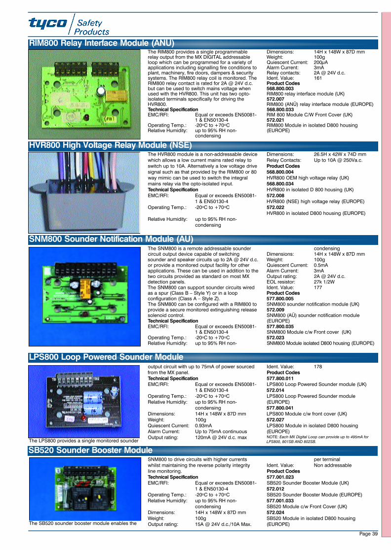
Page 39
The SB520 sounder booster module enables the
SNM800 to drive circuits with higher currentswhilst maintaining the reverse polarity integrityline monitoring. Technical SpecificationEMC/RFI: Equal or exceeds EN50081-
1 & EN50130-4Operating Temp.: -20oC to +70oCRelative Humidity: up to 95% RH non-
condensingDimensions: 14H x 148W x 87D mm Weight: 100gOutput rating: 15A @ 24V d.c./10A Max.
per terminalIdent. Value: Non addressableProduct Codes577.001.023SB520 Sounder Booster Module (UK)572.012SB520 Sounder Booster Module (EUROPE)577.001.033SB520 Module c/w Front Cover (UK)572.024SB520 Module in isolated D800 housing(EUROPE)
SB520 Sounder Booster ModuleThe LPS800 provides a single monitored sounder
output circuit with up to 75mA of power sourcedfrom the MX panel. Technical SpecificationEMC/RFI: Equal or exceeds EN50081-
1 & EN50130-4Operating Temp.: -20oC to +70oCRelative Humidity: up to 95% RH non-
condensingDimensions: 14H x 148W x 87D mm Weight: 100gQuiescent Current: 0.93mAAlarm Current: Up to 75mA continuousOutput rating: 120mA @ 24V d.c. max
Ident. Value: 178Product Codes577.800.011LPS800 Loop Powered Sounder module (UK)572.014LPS800 Loop Powered Sounder module(EUROPE)577.800.041LPS800 Module c/w front cover (UK)572.027LPS800 Module in isolated D800 housing(EUROPE)NOTE: Each MX Digital Loop can provide up to 495mA forLPS800, 801SB AND 802SB.
LPS800 Loop Powered Sounder Module
The SNM800 is a remote addressable soundercircuit output device capable of switchingsounder and speaker circuits up to 2A @ 24V d.c.or provide a monitored output facility for otherapplications. These can be used in addition to thetwo circuits provided as standard on most MXdetection panels.The SNM800 can support sounder circuits wiredas a spur (Class B – Style Y) or in a loopconfiguration (Class A – Style Z).The SNM800 can be configured with a RIM800 toprovide a secure monitored extinguishing releasesolenoid control.Technical SpecificationEMC/RFI: Equal or exceeds EN50081-
1 & EN50130-4Operating Temp.: -20oC to +70oCRelative Humidity: up to 95% RH non-
condensingDimensions: 14H x 148W x 87D mm Weight: 100gQuiescent Current: 0.5mAAlarm Current: 3mAOutput rating: 2A @ 24V d.c.EOL resistor: 27k 1/2WIdent. Value: 177Product Codes577.800.005SNM800 sounder notification module (UK)572.009SNM800 (AÜ) sounder notification module(EUROPE)577.800.035SNM800 Module c/w Front cover (UK)572.023SNM800 Module isolated D800 housing (EUROPE)
SNM800 Sounder Notification Module (AÜ)
The RIM800 provides a single programmablerelay output from the MX DIGITAL addressableloop which can be programmed for a variety ofapplications including signalling fire conditions toplant, machinery, fire doors, dampers & securitysystems. The RIM800 relay coil is monitored. TheRIM800 relay contact is rated for 2A @ 24V d.c.but can be used to switch mains voltage whenused with the HVR800. This unit has two opto-isolated terminals specifically for driving theHVR800.Technical SpecificationEMC/RFI: Equal or exceeds EN50081-
1 & EN50130-4Operating Temp.: -20oC to +70oCRelative Humidity: up to 95% RH non-
condensing
Dimensions: 14H x 148W x 87D mm Weight: 100gQuiescent Current: 200µAAlarm Current: 3mARelay contacts: 2A @ 24V d.c.Ident. Value: 161Product Codes568.800.003RIM800 relay interface module (UK)572.007RIM800 (ANÜ) relay interface module (EUROPE)568.800.033RIM 800 Module C/W Front Cover (UK)572.021RIM800 Module in isolated D800 housing(EUROPE)
RIM800 Relay Interface Module (ANÜ)
The HVR800 module is a non-addressable devicewhich allows a low current mains rated relay toswitch up to 10A. Alternatively a low voltage drivesignal such as that provided by the RIM800 or 80way mimic can be used to switch the integralmains relay via the opto-isolated input.Technical SpecificationEMC/RFI: Equal or exceeds EN50081-
1 & EN50130-4Operating Temp.: -20oC to +70oC
Relative Humidity: up to 95% RH non-condensing
Dimensions: 26.5H x 42W x 74D mmRelay Contacts: Up to 10A @ 250Va.c.Product Codes568.800.004HVR800 OEM high voltage relay (UK)568.800.034HVR800 in isolated D 800 housing (UK)572.008HVR800 (NSE) high voltage relay (EUROPE)572.022HVR800 in isolated D800 housing (EUROPE)
HVR800 High Voltage Relay Module (NSE)
23SeptMXCat. qxd 11/10/02 11:44 pm Page 39
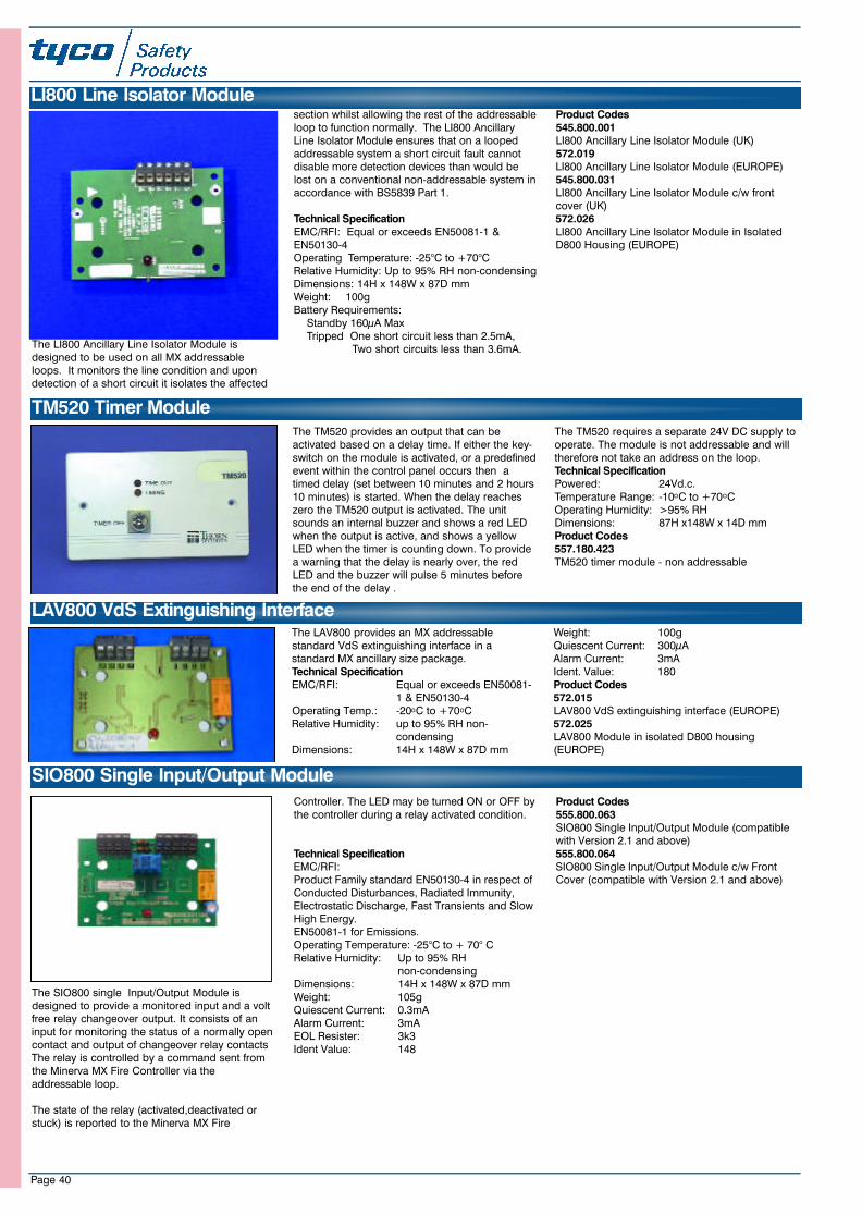
Page 40
The LI800 Ancillary Line Isolator Module isdesigned to be used on all MX addressableloops. It monitors the line condition and upondetection of a short circuit it isolates the affected
section whilst allowing the rest of the addressableloop to function normally. The LI800 AncillaryLine Isolator Module ensures that on a loopedaddressable system a short circuit fault cannotdisable more detection devices than would belost on a conventional non-addressable system inaccordance with BS5839 Part 1.
Technical SpecificationEMC/RFI: Equal or exceeds EN50081-1 &EN50130-4Operating Temperature: -25°C to +70°CRelative Humidity: Up to 95% RH non-condensingDimensions: 14H x 148W x 87D mmWeight: 100gBattery Requirements:
Standby 160µA MaxTripped One short circuit less than 2.5mA,
Two short circuits less than 3.6mA.
Product Codes545.800.001LI800 Ancillary Line Isolator Module (UK)572.019LI800 Ancillary Line Isolator Module (EUROPE)545.800.031LI800 Ancillary Line Isolator Module c/w frontcover (UK)572.026LI800 Ancillary Line Isolator Module in IsolatedD800 Housing (EUROPE)
The TM520 provides an output that can beactivated based on a delay time. If either the key-switch on the module is activated, or a predefinedevent within the control panel occurs then atimed delay (set between 10 minutes and 2 hours10 minutes) is started. When the delay reacheszero the TM520 output is activated. The unitsounds an internal buzzer and shows a red LEDwhen the output is active, and shows a yellowLED when the timer is counting down. To providea warning that the delay is nearly over, the redLED and the buzzer will pulse 5 minutes beforethe end of the delay .
The TM520 requires a separate 24V DC supply tooperate. The module is not addressable and willtherefore not take an address on the loop.Technical SpecificationPowered: 24Vd.c.Temperature Range: -10oC to +70oCOperating Humidity: >95% RHDimensions: 87H x148W x 14D mmProduct Codes557.180.423TM520 timer module - non addressable
TM520 Timer Module
The LAV800 provides an MX addressablestandard VdS extinguishing interface in astandard MX ancillary size package.Technical SpecificationEMC/RFI: Equal or exceeds EN50081-
1 & EN50130-4Operating Temp.: -20oC to +70oCRelative Humidity: up to 95% RH non-
condensingDimensions: 14H x 148W x 87D mm
Weight: 100gQuiescent Current: 300µAAlarm Current: 3mAIdent. Value: 180Product Codes572.015LAV800 VdS extinguishing interface (EUROPE)572.025LAV800 Module in isolated D800 housing(EUROPE)
LAV800 VdS Extinguishing Interface
LI800 Line Isolator Module
The SIO800 single Input/Output Module isdesigned to provide a monitored input and a voltfree relay changeover output. It consists of aninput for monitoring the status of a normally opencontact and output of changeover relay contactsThe relay is controlled by a command sent fromthe Minerva MX Fire Controller via theaddressable loop.
The state of the relay (activated,deactivated or stuck) is reported to the Minerva MX Fire
Controller. The LED may be turned ON or OFF bythe controller during a relay activated condition.
Technical SpecificationEMC/RFI:Product Family standard EN50130-4 in respect ofConducted Disturbances, Radiated Immunity,Electrostatic Discharge, Fast Transients and SlowHigh Energy.EN50081-1 for Emissions.Operating Temperature: -25°C to + 70° CRelative Humidity: Up to 95% RH
non-condensingDimensions: 14H x 148W x 87D mmWeight: 105gQuiescent Current: 0.3mAAlarm Current: 3mAEOL Resister: 3k3Ident Value: 148
Product Codes555.800.063SIO800 Single Input/Output Module (compatiblewith Version 2.1 and above)555.800.064SIO800 Single Input/Output Module c/w FrontCover (compatible with Version 2.1 and above)
SIO800 Single Input/Output Module
23SeptMXCat. qxd 11/10/02 11:44 pm Page 40
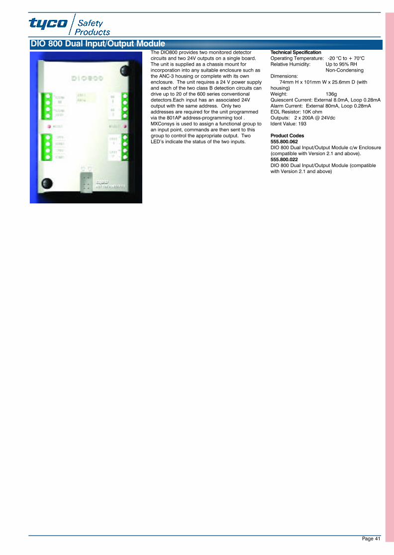
The DIO800 provides two monitored detectorcircuits and two 24V outputs on a single board.The unit is supplied as a chassis mount forincorporation into any suitable enclosure such asthe ANC-3 housing or complete with its ownenclosure. The unit requires a 24 V power supplyand each of the two class B detection circuits candrive up to 20 of the 600 series conventionaldetectors.Each input has an associated 24Voutput with the same address. Only twoaddresses are required for the unit programmedvia the 801AP address-programming tool .MXConsys is used to assign a functional group toan input point, commands are then sent to thisgroup to control the appropriate output. TwoLED’s indicate the status of the two inputs.
Technical SpecificationOperating Temperature: -20 °C to + 70°CRelative Humidity: Up to 95% RH
Non-CondensingDimensions:
74mm H x 101mm W x 25.6mm D (withhousing)Weight: 136gQuiescent Current: External 8.0mA, Loop 0.28mAAlarm Current: External 80mA, Loop 0.28mAEOL Resistor: 10K ohmOutputs: 2 x 200A @ 24VdcIdent Value: 193
Product Codes555.800.062DIO 800 Dual Input/Output Module c/w Enclosure(compatible with Version 2.1 and above).555.800.022DIO 800 Dual Input/Output Module (compatiblewith Version 2.1 and above)
DIO 800 Dual Input/Output Module
Page 41
23SeptMXCat. qxd 11/10/02 11:44 pm Page 41
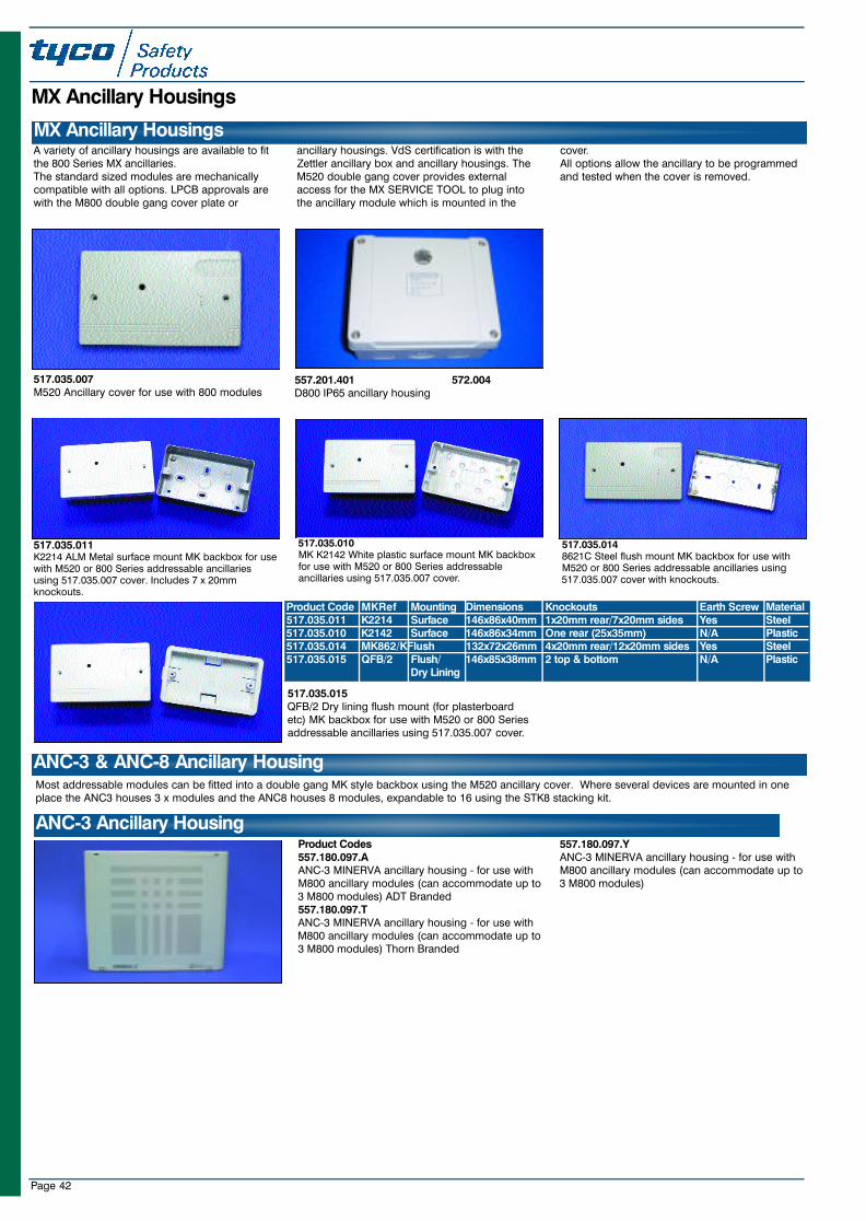
Page 42
MX Ancillary Housings
A variety of ancillary housings are available to fitthe 800 Series MX ancillaries.The standard sized modules are mechanicallycompatible with all options. LPCB approvals arewith the M800 double gang cover plate or
ancillary housings. VdS certification is with theZettler ancillary box and ancillary housings. TheM520 double gang cover provides externalaccess for the MX SERVICE TOOL to plug intothe ancillary module which is mounted in the
cover.All options allow the ancillary to be programmedand tested when the cover is removed.
MX Ancillary Housings
517.035.007M520 Ancillary cover for use with 800 modules
557.201.401 572.004D800 IP65 ancillary housing
517.035.011K2214 ALM Metal surface mount MK backbox for usewith M520 or 800 Series addressable ancillariesusing 517.035.007 cover. Includes 7 x 20mmknockouts.
517.035.010MK K2142 White plastic surface mount MK backboxfor use with M520 or 800 Series addressableancillaries using 517.035.007 cover.
517.035.0148621C Steel flush mount MK backbox for use withM520 or 800 Series addressable ancillaries using517.035.007 cover with knockouts.
517.035.015QFB/2 Dry lining flush mount (for plasterboardetc) MK backbox for use with M520 or 800 Seriesaddressable ancillaries using 517.035.007 cover.
Product Code MKRef Mounting Dimensions Knockouts Earth Screw Material517.035.011 K2214 Surface 146x86x40mm 1x20mm rear/7x20mm sides Yes Steel517.035.010 K2142 Surface 146x86x34mm One rear (25x35mm) N/A Plastic517.035.014 MK862/KFlush 132x72x26mm 4x20mm rear/12x20mm sides Yes Steel517.035.015 QFB/2 Flush/ 146x85x38mm 2 top & bottom N/A Plastic
Dry Lining
Most addressable modules can be fitted into a double gang MK style backbox using the M520 ancillary cover. Where several devices are mounted in oneplace the ANC3 houses 3 x modules and the ANC8 houses 8 modules, expandable to 16 using the STK8 stacking kit.
ANC-3 & ANC-8 Ancillary Housing
Product Codes557.180.097.AANC-3 MINERVA ancillary housing - for use withM800 ancillary modules (can accommodate up to3 M800 modules) ADT Branded557.180.097.TANC-3 MINERVA ancillary housing - for use withM800 ancillary modules (can accommodate up to3 M800 modules) Thorn Branded
557.180.097.YANC-3 MINERVA ancillary housing - for use withM800 ancillary modules (can accommodate up to3 M800 modules)
ANC-3 Ancillary Housing
23SeptMXCat. qxd 11/10/02 11:44 pm Page 42
Page 43
Product CodesUK EUROPE557.180.096.AANC-8 MINERVA ancillary housing - for use withX800 ancillary modules (can accommodate up to16 X800 modules with stacking kit) ADT Branded557.180.096.TA N C-8 MINERVA ancillary housing - for use withX800 ancillary modules (can accommodate up to 16X800 modules with stacking kit) Thorn Branded
557.180.096.Y 572.034ANC-8 MINERVA ancillary housing - for use withX800 ancillary modules (can accommodate up to16 X800 modules with stacking kit) 557.180.095 572.036STK-8 MINERVA ancillary stacking kit for use withANC-8 ancillary housing
ANC-8 Ancillary Housing
Detectors have a special address flag for carrying theaddress labels - details in the detector section. Forother devices or on detectors where zone informationis also required a series of address labels areavailable.Numbered 1 to 250 the address labels are availablein 4 different colours to distinguish between differentloops. In addition small zone labels can be fixed tothe address labels.
Product CodesZone Labels599.047.011Zone labels - Zones 1 - 16599.047.012Zone labels - Zones 17 - 32599.047.013Zone labels - Zones 33 - 48599.047.014Zone labels - Zones 49 - 64599.047.015Zone labels - Zones 65 - 80599.047.016Zone labels - Zones 81 - 100599.047.018Zone labels - Zones 101 - 120599.047.019Zone labels - Zones 121 - 140599.047.020Zone labels - Zones 141 - 160599.047.021Zone labels - Zones 161 - 180599.047.022Zone labels - Zones 181 - 200599.047.023Zone labels - Zones 201 - 220
599.047.024Zone labels - Zones 221 - 240Address Labels599.047.030Address Labels 1 - 250 Loop A - White599.047.031Address Labels 1 - 250 Loop B - Yellow599.047.032Address Labels 1 - 250 Loop C - Purple599.047.033Address Labels 1 - 250 Loop D - Green
Callpoint & Ancillary Address Labels
23SeptMXCat. qxd 11/10/02 11:44 pm Page 43
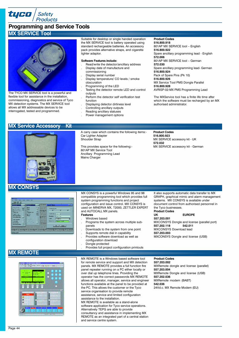
Page 44
MX CONSYS is a powerful Windows 95 and 98compatible programming tool which provides fullsystem programming functions and projectconfiguration and issue control. MX CONSYS isused on MINERVA MX, T2000, ZETTLER EXPERTand AUTOCALL MX panels. Features. Windows based. Programs the system across multiple sub-
panels. Downloads to the system from one point. Supports remote dial in capability. Provides software download as well as
configuration download. Dongle protected. Provides full project configuration printouts
It also supports automatic data transfer to MXGRAPH, graphical mimic and alarm managementsystems. MX CONSYS is available underdocument control from authorised personnel inthe Tyco businesses.Product CodesUK EUROPE557.203.001MXCONSYS Dongle and license (parallel port)557.202.118 542.011MXCONSYS Download lead557.203.003MXCONSYS Dongle and license (USB)
MX CONSYS
Programming and Service Tools
The TYCO MX SERVICE tool is a powerful andflexible tool for assistance in the installation,commissioning, diagnostics and service of TycoMX detection systems. The MX SERVICE toolallows all MX addressable devices to beinterrogated, tested and programmed.
Suitable for desktop or single handed operationthe MX SERVICE tool is battery operated usingstandard rechargeable batteries. An accessorypack provides alternative straps, and cigarettelighter adaptor.
Software Features include:. Read/write the detector/ancillary address. Display date of manufacture and
commissioning. Display serial number. Display temperature/ CO levels / smoke
obscuration. Programming of the LED. Testing the detector remote LED and control
outputs. Perform the detector self verification test
function. Displaying detector dirtiness level. Controlling ancillary outputs. Reading ancillary statuses. Power management options
Product Codes516.800.918801AP MX SERVICE tool – English516.800.922Spare ancillary programming lead - English572.006801AP MX SERVICE tool – German572.030Spare ancillary programming lead- German516.800.924Pack of Spare Pins (Pk 10)516.800.926MX Service Tool PMS Dongle Parallel516.800.928AVRISP-02-MX PMS Programming Lead
The MXService tool has a finite life time afterwhich the software must be recharged by an MXauthorised administrator.
MX SERVICE Tool
MX REMOTE is a Windows based software toolfor remote service and support and MX detectionpanels. MX REMOTE provides a full function firepanel repeater running on a PC either locally orover dial up telephone lines. Providing theoperator has the correct passwords MX REMOTEallows all operator, manager, service and engineerfunctions available at the panel to be provided atthe PC. This allows the customer or the Tycoservice organisation to provide remoteassistance, service and limited configurationassistance to the installation.MX REMOTE is available as a stand-alonesoftware application for Tyco service operations.Alternatively TEPG are able to provideconsultancy and assistance in implementing MXREMOTE as an integrated part of a central stationand service centre system.
Product Codes557.203.002MXRemote dongle and license (parallel)557.203.004MXRemote Dongle and license (USB)557.202.036MXRemote modem (BABT)542.03624Vd.c. MX Remote Modem (EU)
MX REMOTE
MX Service Accessory KitA carry case which contains the following items:-Car Lighter AdapterShoulder Strap
This provides space for the following:-801AP MX Service ToolAncillary Programming Lead Mains Charger
Product Codes 516.800.923MX SERVICE accessory kit - UK572.032MX SERVICE accessory kit - German
23SeptMXCat. qxd 11/10/02 11:44 pm Page 44

Page 45
The 800RT detector removal tool fits the SOLOrange of telescopic poles and allows the 800Series detectors to be remotely fitted, removedand turned to the “park” position. The tool alsoenables detector dust covers to be easilyremoved.The 800RT is also compatible for use with M600and M900 Series Low Profile detectors.
Product Codes516.800.917800RT removal tool572.005800RT removal tool with ZETTLER pole adaptor
800RT Detector Removal Tool
Sales Tools
Product CodesPSV001Carbon Monoxide Low Profile detector - EnglishPALformatPSV008Tyco MX Technology - English PALformatPSV009Tyco MX Technology - English NTSCformatPSV010Tyco MX Technology - German PAL format
PSV011Tyco MX Technology - Dutch PAL format PSV012Tyco MX Technology - Spanish PAL formatPSV013Tyco MX Technology - Spanish NTSC formatPBMX01Tyco MX Technology Brochure - English versionPBMX01ETyco MX Technology Brochure - Spanish version
517.001.230
SOLO100 Telescopic extension pole 1.26M to4.5M long
517.001.226
SOLO101 Extension tube 1.3M long for use with517.001.230 telescopic extension pole
517.001.228
SOLO600 Carry all bag for detector test kit
517.001.242
SOLO720 Spare battery baton for use with SOLO450/460 tester
517.001.243
SOLO724 Spare mains/car battery charger forSOLO720 battery baton
517.001.264
SOLO 610 Protective Carry/Storage Bag for SoloDetector Test Kit
5 1 7 . 0 0 1 . 2 5 4
S O LO461 Cordless heat detector tester kit including:S O LO460 tester, SOLO720 battery batons andS O LO724 charger. (Connects directly toS O LO100/101 poles).
SOLO Detector Service Equipment
5 1 7 . 0 0 1 . 2 5 5
S O LO330 Aerosol dispenser for use with all detectorranges. Connects directly to SOLO100/101 poles
517.001.224
SOLO704 Adaptor tube B - Adapts SOLO100/101pole sets for TYCO detector changers and testers
5 7 1 . 0 0 1 . 2 5 6
Suretest Solo aerosol tester can. For use withS O LO330 dispenser. Non-flammable, ozone andenvironment friendly. Approx 200 tests per can
5 1 7 . 0 0 1 . 2 3 3
CO Detector field test kit with 24 brickets for use withS O LO 3 3 0
5 1 7 . 0 0 1 . 2 3 4
CO Fire Detector field test kit spare bricks (Pack of2 4 )
Videos & Brochures
MX DEMO CASEAn MX Panel, 801CH Detector, 801PH Detector,LED’s and Switches mounted in a carry case andpre-configured with demo software.
Product Code557.200.901
Product Codes
23SeptMXCat. qxd 11/10/02 11:44 pm Page 45
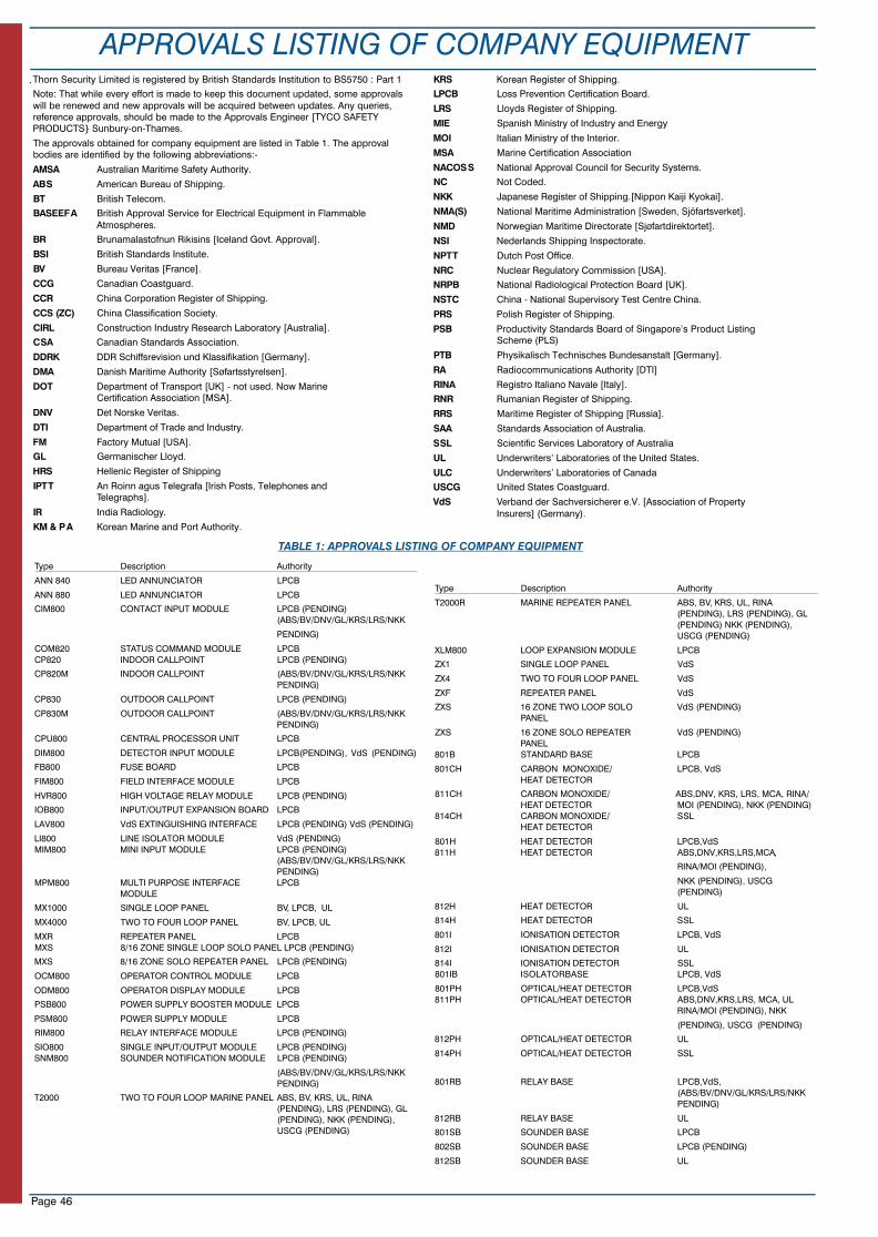
Page 46
APPROVALS LISTING OF COMPANY EQUIPMENTThorn Security Limited is registered by British Standards Institution to BS5750 : Part 1
Note: That while every effort is made to keep this document updated, some approvalswill be renewed and new approvals will be acquired between updates. Any queries,reference approvals, should be made to the Approvals Engineer [TYCO SAFETYPRODUCTS} Sunbury-on-Thames.
The approvals obtained for company equipment are listed in Table 1. The approvalbodies are identified by the following abbreviations:-
AMSA Australian Maritime Safety Authority.
ABS American Bureau of Shipping.
BT British Telecom.
BASEEFA British Approval Service for Electrical Equipment in Flammable Atmospheres.
BR Brunamalastofnun Rikisins [Iceland Govt. Approval].
BSI British Standards Institute.
BV Bureau Veritas [France].
CCG Canadian Coastguard.
CCR China Corporation Register of Shipping.
CCS (ZC) China Classification Society.
CIRL Construction Industry Research Laboratory [Australia].
CSA Canadian Standards Association.
DDRK DDR Schiffsrevision und Klassifikation [Germany].
DMA Danish Maritime Authority [Søfartsstyrelsen].
DOT Department of Transport [UK] - not used. Now Marine Certification Association [MSA].
DNV Det Norske Veritas.
DTI Department of Trade and Industry.
FM Factory Mutual [USA].
GL Germanischer Lloyd.
HRS Hellenic Register of Shipping
IPTT An Roinn agus Telegrafa [Irish Posts, Telephones and Telegraphs].
IR India Radiology.
KM & P A Korean Marine and Port Authority.
KRS Korean Register of Shipping.
LPCB Loss Prevention Certification Board.
LRS Lloyds Register of Shipping.
MIE Spanish Ministry of Industry and Energy
MOI Italian Ministry of the Interior.
MSA Marine Certification Association
NACOSS National Approval Council for Security Systems.
NC Not Coded.
NKK Japanese Register of Shipping.[Nippon Kaiji Kyokai].
NMA(S) National Maritime Administration [Sweden, Sjöfartsverket].
NMD Norwegian Maritime Directorate [Sjøfartdirektortet].
NSI Nederlands Shipping Inspectorate.
NPTT Dutch Post Office.
NRC Nuclear Regulatory Commission [USA].
NRPB National Radiological Protection Board [UK].
NSTC China - National Supervisory Test Centre China.
PRS Polish Register of Shipping.
PSB Productivity Standards Board of Singapore’s Product Listing Scheme (PLS)
PTB Physikalisch Technisches Bundesanstalt [Germany].
RA Radiocommunications Authority [DTI]
RINA Registro Italiano Navale [Italy].
RNR Rumanian Register of Shipping.
RRS Maritime Register of Shipping [Russia].
SAA Standards Association of Australia.
SSL Scientific Services Laboratory of Australia
UL Underwriters’ Laboratories of the United States.
ULC Underwriters’ Laboratories of Canada
USCG United States Coastguard.
VdS Verband der Sachversicherer e.V. [Association of Property Insurers] (Germany).
Type Description Authority
ANN 840 LED ANNUNCIATOR LPCB
ANN 880 LED ANNUNCIATOR LPCB
CIM800 CONTACT INPUT MODULE LPCB (PENDING) (ABS/BV/DNV/GL/KRS/LRS/NKK
PENDING)
COM820 STATUS COMMAND MODULE LPCBCP820 INDOOR CALLPOINT LPCB (PENDING)
CP820M INDOOR CALLPOINT (ABS/BV/DNV/GL/KRS/LRS/NKK PENDING)
CP830 OUTDOOR CALLPOINT LPCB (PENDING)
CP830M OUTDOOR CALLPOINT (ABS/BV/DNV/GL/KRS/LRS/NKK PENDING)
CPU800 CENTRAL PROCESSOR UNIT LPCB
DIM800 DETECTOR INPUT MODULE LPCB(PENDING), VdS (PENDING)
FB800 FUSE BOARD LPCB
FIM800 FIELD INTERFACE MODULE LPCB
HVR800 HIGH VOLTAGE RELAY MODULE LPCB (PENDING)
IOB800 INPUT/OUTPUT EXPANSION BOARD LPCB
LAV800 VdS EXTINGUISHING INTERFACE LPCB (PENDING) VdS (PENDING)
LI800 LINE ISOLATOR MODULE VdS (PENDING)MIM800 MINI INPUT MODULE LPCB (PENDING)
(ABS/BV/DNV/GL/KRS/LRS/NKK PENDING)
MPM800 MULTI PURPOSE INTERFACE LPCBMODULE
MX1000 SINGLE LOOP PANEL BV, LPCB, UL
MX4000 TWO TO FOUR LOOP PANEL BV, LPCB, UL
MXR REPEATER PANEL LPCBMXS 8/16 ZONE SINGLE LOOP SOLO PANEL LPCB (PENDING)
MXS 8/16 ZONE SOLO REPEATER PANEL LPCB (PENDING)
OCM800 OPERATOR CONTROL MODULE LPCB
ODM800 OPERATOR DISPLAY MODULE LPCB
PSB800 POWER SUPPLY BOOSTER MODULE LPCB
PSM800 POWER SUPPLY MODULE LPCB
RIM800 RELAY INTERFACE MODULE LPCB (PENDING)
SIO800 SINGLE INPUT/OUTPUT MODULE LPCB (PENDING)SNM800 SOUNDER NOTIFICATION MODULE LPCB (PENDING)
(ABS/BV/DNV/GL/KRS/LRS/NKK PENDING)
T2000 TWO TO FOUR LOOP MARINE PANEL ABS, BV, KRS, UL, RINA (PENDING), LRS (PENDING), GL (PENDING), NKK (PENDING), USCG (PENDING)
Type Description Authority
T2000R MARINE REPEATER PANEL ABS, BV, KRS, UL, RINA (PENDING), LRS (PENDING), GL (PENDING) NKK (PENDING), USCG (PENDING)
XLM800 LOOP EXPANSION MODULE LPCB
ZX1 SINGLE LOOP PANEL VdS
ZX4 TWO TO FOUR LOOP PANEL VdS
ZXF REPEATER PANEL VdS
ZXS 16 ZONE TWO LOOP SOLO VdS (PENDING)PANEL
ZXS 16 ZONE SOLO REPEATER VdS (PENDING)PANEL
801B STANDARD BASE LPCB
801CH CARBON MONOXIDE/ LPCB, VdSHEAT DETECTOR
811CH CARBON MONOXIDE/ ABS,DNV, KRS, LRS, MCA, RINA/ HEAT DETECTOR MOI (PENDING), NKK (PENDING)
814CH CARBON MONOXIDE/ SSLHEAT DETECTOR
801H HEAT DETECTOR LPCB,VdS 811H HEAT DETECTOR ABS,DNV,KRS,LRS,MCA,
RINA/MOI (PENDING),
NKK (PENDING), USCG (PENDING)
812H HEAT DETECTOR UL
814H HEAT DETECTOR SSL
801I IONISATION DETECTOR LPCB, VdS
812I IONISATION DETECTOR UL
814I IONISATION DETECTOR SSL801IB ISOLATORBASE LPCB, VdS
801PH OPTICAL/HEAT DETECTOR LPCB,VdS 811PH OPTICAL/HEAT DETECTOR ABS,DNV,KRS,LRS, MCA, UL
RINA/MOI (PENDING), NKK
(PENDING), USCG (PENDING)
812PH OPTICAL/HEAT DETECTOR UL
814PH OPTICAL/HEAT DETECTOR SSL
801RB RELAY BASE LPCB,VdS, (ABS/BV/DNV/GL/KRS/LRS/NKK PENDING)
812RB RELAY BASE UL
801SB SOUNDER BASE LPCB
802SB SOUNDER BASE LPCB (PENDING)
812SB SOUNDER BASE UL
TABLE 1: APPROVALS LISTING OF COMPANY EQUIPMENT
23SeptMXCat. qxd 11/10/02 11:44 pm Page 46
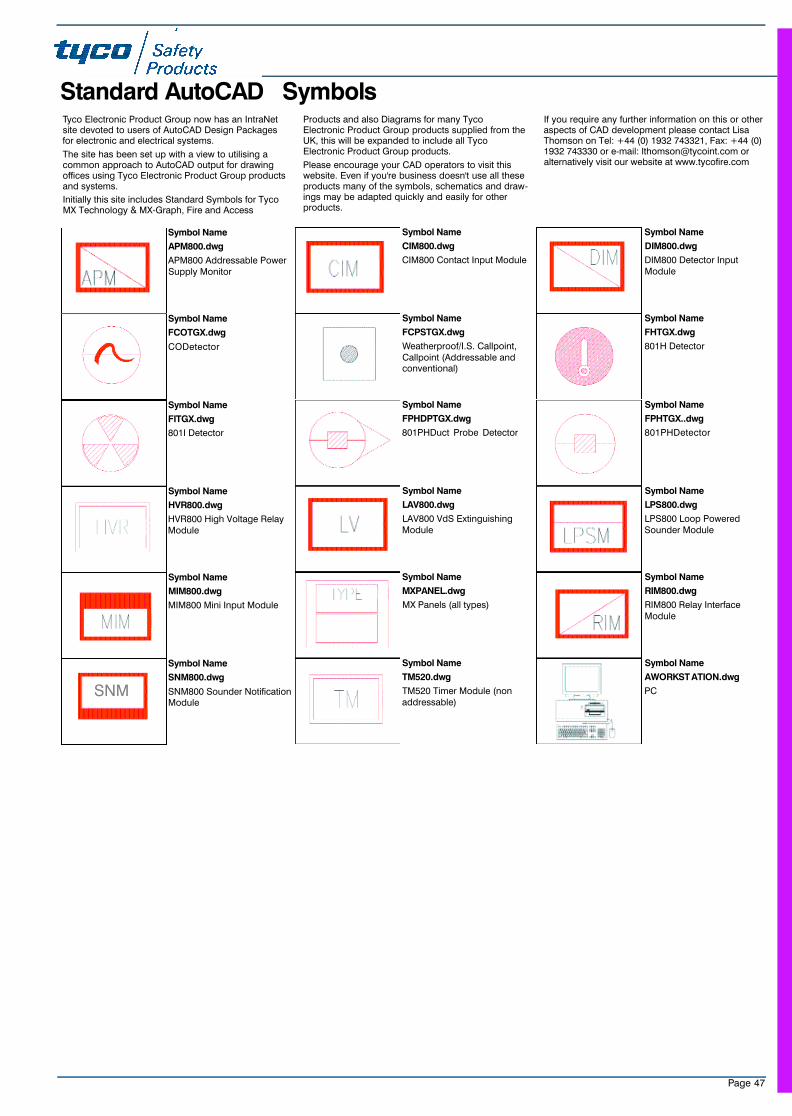
Page 47
Standard AutoCAD SymbolsTyco Electronic Product Group now has an IntraNetsite devoted to users of AutoCAD Design Packagesfor electronic and electrical systems.
The site has been set up with a view to utilising acommon approach to AutoCAD output for drawingoffices using Tyco Electronic Product Group productsand systems.
Initially this site includes Standard Symbols for TycoMX Technology & MX-Graph, Fire and Access
Products and also Diagrams for many TycoElectronic Product Group products supplied from theUK, this will be expanded to include all TycoElectronic Product Group products.
Please encourage your CAD operators to visit thiswebsite. Even if you're business doesn't use all theseproducts many of the symbols, schematics and draw-ings may be adapted quickly and easily for otherproducts.
If you require any further information on this or otheraspects of CAD development please contact LisaThomson on Tel: +44 (0) 1932 743321, Fax: +44 (0)1932 743330 or e-mail: [email protected] oralternatively visit our website at www.tycofire.com
Symbol Name
APM800.dwg
APM800 Addressable PowerSupply Monitor
Symbol Name
CIM800.dwg
CIM800 Contact Input Module
Symbol Name
DIM800.dwg
DIM800 Detector InputModule
Symbol Name
FCOTGX.dwg
CODetector
Symbol Name
FCPSTGX.dwg
Weatherproof/I.S. Callpoint,Callpoint (Addressable andconventional)
Symbol Name
FHTGX.dwg
801H Detector
Symbol Name
FITGX.dwg
801I Detector
Symbol Name
FPHDPTGX.dwg
801PHDuct Probe Detector
Symbol Name
FPHTGX..dwg
801PHDetector
Symbol Name
HVR800.dwg
HVR800 High Voltage RelayModule
Symbol Name
LAV800.dwg
LAV800 VdS ExtinguishingModule
Symbol Name
LPS800.dwg
LPS800 Loop PoweredSounder Module
Symbol Name
MIM800.dwg
MIM800 Mini Input Module
Symbol Name
MXPANEL.dwg
MX Panels (all types)
Symbol Name
RIM800.dwg
RIM800 Relay InterfaceModule
Symbol Name
SNM800.dwg
SNM800 Sounder NotificationModule
Symbol Name
TM520.dwg
TM520 Timer Module (nonaddressable)
Symbol Name
AWORKST ATION.dwg
PCSNM
23SeptMXCat. qxd 11/10/02 11:44 pm Page 47
The right is reserved to modify or withdraw anyproduct or service without notice
©Tyco Safety Products 2002www.tycosafetyproducts-europe.com
Sales Order Processing (UK)Walthamstow +44 (0) 208 919 4000
Quality Assurance (UK)Walthamstow +44 (0) 208 919 4000
Manufacturing (UK)Walthamstow +44 (0) 208 919 4000
Customer Services (UK)Walthamstow +44 (0) 208 919 6202
Walthamstow160 Billet RoadWalthamstowLondonE17 5DRTelephone: +44 (0) 208 919 4000Facsimile: +44 (0) 208 919 4040
Distribution Centre (UK)Letchworth +44 (0) 1462 667 700
LetchworthDunhams LaneLetchworthHerts.SG6 1BDTelephone: +44 (0) 1 462 667 700Facsimile: +44 (0) 1 462 667 777
Product ManagementSunbury +44 (0) 1932 743327
Field SupportSunbury +44 (0) 1932 743327
Research & Development (UK)Sunbury +44 (0) 1932 743333
HelpdeskSunbury
Tel: +44 (0) 1932 743327Fax: +44 (0) 1932 743330
SunburyThe Summit, Hanworth RoadSunbury On ThamesMiddlesex TW16 5DBTelephone: +44 (0) 1932 743333Facsimile: +44 (0) 1932 743330
Who’s Where?
Product Catalogue PMC08 Issue 3
MXcatCOVandback.QXD 11/10/02 11:51 pm Page 2
Related Documents