Multi-channel ultrasonic inspection of a mooring chain for fatigue cracks John R RUDLIN TWI Ltd Granta Park Cambridge CB21 6AL Phone +44 1223 899000 mail [email protected] BP wished to confirm the integrity of a mooring chain in the chain stopper location which had been in service a number of years, and required an inspection technique that would give quantitative information. It was agreed that in order to be conservative the detectable flaw size with 90% probability of detection should be 20mm through wall and 100mm long. The restrictions for the inspection were that it had to be carried out in 15m depth of water inside the turret structure, with no demanding tasks on the diver such as probe scanning because of the difficult water conditions. The cable route from the area was also long with a total distance from the inspection area to the instrument of around 100 metres. The cables pass through a hazardous area so all materials needed to be doubly insulated and protected against sparking of any type. This paper describes the development of the inspection technique and equipment, from concept to mobilisation on site, and some of the results of the inspection. Keywords: Offshore, Modelling and Simulation, Ultrasonic Testing (UT), mooring chain Background BP wished to confirm the integrity of a mooring chain in the chain stopper location which had been in service a number of years, and required an inspection technique that would give quantitative information. It was agreed that in order to be conservative the detectable flaw size with 90% probability of detection should be 20mm through wall and 100mm long. The restrictions for the inspection were that it had to be carried out in 15m depth of water inside the turret structure, with no demanding tasks on the diver such as probe scanning because of the difficult water conditions. The cable route from the area was also long. Figure 1 shows the part of the route near the risers. The total distance was around 100 metres. The cables pass through a hazardous area so all materials needed to be doubly insulated and protected against sparking of any type. It was expected that any planar flaws would have an orientation of 10° and 70° to the minor axis or variations from this, so this had to be taken into account in the design of the equipment. The surface for the inspection was possibly very corroded, and the access conditions are that sometimes Link 1 is tilted with respect to Link 2 which reduces the access for the inspection device. It is worth noting that it was required to produce a system for trials in the space of 10 weeks from the start of the contract. 11th European Conference on Non-Destructive Testing (ECNDT 2014), October 6-10, 2014, Prague, Czech Republic More Info at Open Access Database www.ndt.net/?id=16471

Welcome message from author
This document is posted to help you gain knowledge. Please leave a comment to let me know what you think about it! Share it to your friends and learn new things together.
Transcript
Multi-channel ultrasonic inspection of a mooring chain for fatigue cracks
John R RUDLIN
TWI Ltd Granta Park Cambridge CB21 6AL Phone +44 1223 899000 mail [email protected] BP wished to confirm the integrity of a mooring chain in the chain stopper location which had been in service a number of years, and required an inspection technique that would give quantitative information. It was agreed that in order to be conservative the detectable flaw size with 90% probability of detection should be 20mm through wall and 100mm long.
The restrictions for the inspection were that it had to be carried out in 15m depth of water inside the turret structure, with no demanding tasks on the diver such as probe scanning because of the difficult water conditions. The cable route from the area was also long with a total distance from the inspection area to the instrument of around 100 metres. The cables pass through a hazardous area so all materials needed to be doubly insulated and protected against sparking of any type. This paper describes the development of the inspection technique and equipment, from concept to mobilisation on site, and some of the results of the inspection. Keywords: Offshore, Modelling and Simulation, Ultrasonic Testing (UT), mooring chain
Background BP wished to confirm the integrity of a mooring chain in the chain stopper location which had been in service a number of years, and required an inspection technique that would give quantitative information. It was agreed that in order to be conservative the detectable flaw size with 90% probability of detection should be 20mm through wall and 100mm long. The restrictions for the inspection were that it had to be carried out in 15m depth of water inside the turret structure, with no demanding tasks on the diver such as probe scanning because of the difficult water conditions. The cable route from the area was also long. Figure 1 shows the part of the route near the risers. The total distance was around 100 metres. The cables pass through a hazardous area so all materials needed to be doubly insulated and protected against sparking of any type. It was expected that any planar flaws would have an orientation of 10° and 70° to the minor axis or variations from this, so this had to be taken into account in the design of the equipment. The surface for the inspection was possibly very corroded, and the access conditions are that sometimes Link 1 is tilted with respect to Link 2 which reduces the access for the inspection device. It is worth noting that it was required to produce a system for trials in the space of 10 weeks from the start of the contract.
11th European Conference on Non-Destructive Testing (ECNDT 2014), October 6-10, 2014, Prague, Czech RepublicM
ore
Info
at O
pen
Acc
ess
Dat
abas
e w
ww
.ndt
.net
/?id
=16
471
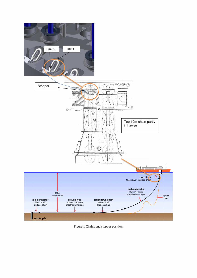
Figure 1 Chains and stopper position.
400m
waterdepth
pile connector55m x 6.25”
studless chain
ground wire1000m x140mmØ
sheathed wire rope
flexibleriser
touchdown chain292m x 6.25”
studless chain
mid-water wire440m x146mmØ
sheathed wire rope
top chain10m x 6.25” studless chain
anchor pile
400m
waterdepth
pile connector55m x 6.25”
studless chain
ground wire1000m x140mmØ
sheathed wire rope
flexibleriser
touchdown chain292m x 6.25”
studless chain
mid-water wire440m x146mmØ
sheathed wire rope
top chain10m x 6.25” studless chain
anchor pile
Stopper
Top 10m chain partly in hawse
Link 2 Link 1
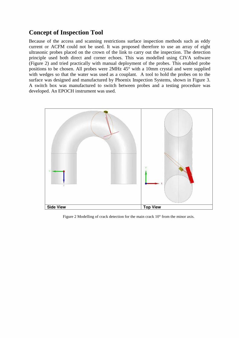
Concept of Inspection Tool Because of the access and scanning restrictions surface inspection methods such as eddy current or ACFM could not be used. It was proposed therefore to use an array of eight ultrasonic probes placed on the crown of the link to carry out the inspection. The detection principle used both direct and corner echoes. This was modelled using CIVA software (Figure 2) and tried practically with manual deployment of the probes. This enabled probe positions to be chosen. All probes were 2MHz 45° with a 10mm crystal and were supplied with wedges so that the water was used as a couplant. A tool to hold the probes on to the surface was designed and manufactured by Phoenix Inspection Systems, shown in Figure 3. A switch box was manufactured to switch between probes and a testing procedure was developed. An EPOCH instrument was used.
Side View Top View
Figure 2 Modelling of crack detection for the main crack 10° from the minor axis.
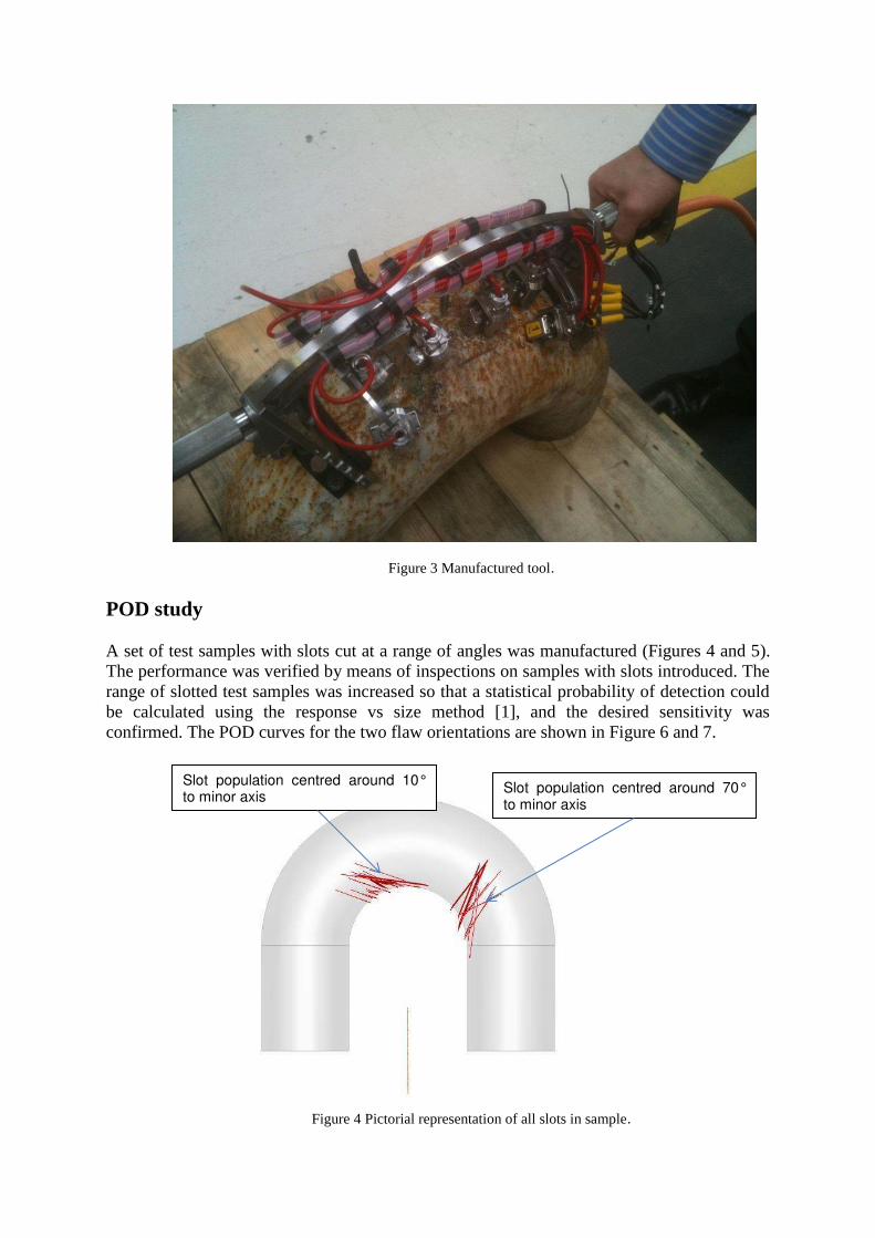
Figure 3 Manufactured tool.
POD study A set of test samples with slots cut at a range of angles was manufactured (Figures 4 and 5). The performance was verified by means of inspections on samples with slots introduced. The range of slotted test samples was increased so that a statistical probability of detection could be calculated using the response vs size method [1], and the desired sensitivity was confirmed. The POD curves for the two flaw orientations are shown in Figure 6 and 7.
Figure 4 Pictorial representation of all slots in sample.
Slot population centred around 70° to minor axis
Slot population centred around 10° to minor axis
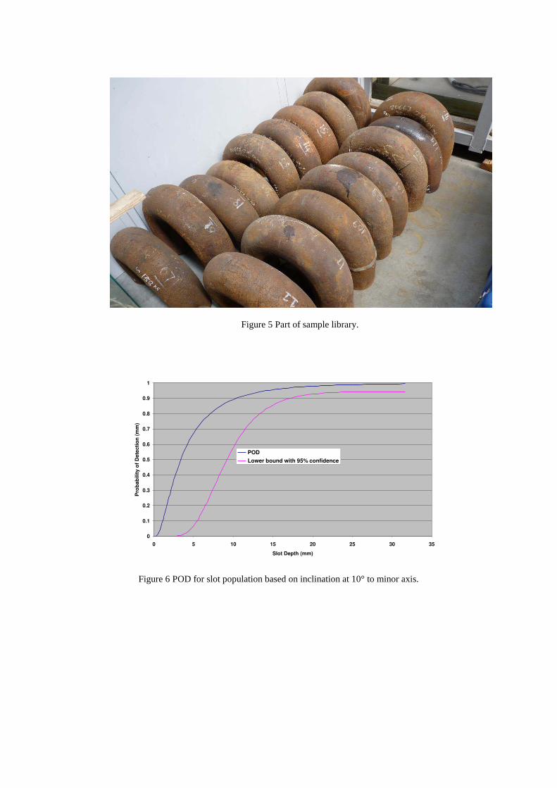
Figure 5 Part of sample library.
Figure 6 POD for slot population based on inclination at 10° to minor axis.
0
0.1
0.2
0.3
0.4
0.5
0.6
0.7
0.8
0.9
1
0 5 10 15 20 25 30 35
Slot Depth (mm)
Pro
bab
ilit
y o
f D
ete
cti
on
(m
m)
POD
Lower bound with 95% confidence
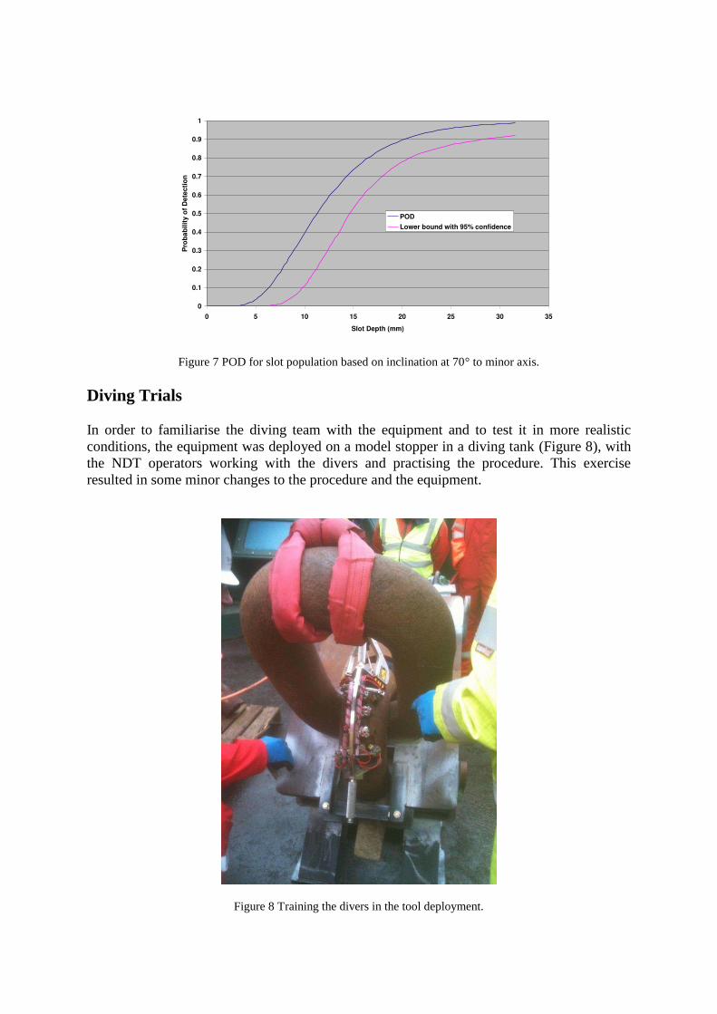
Figure 7 POD for slot population based on inclination at 70° to minor axis. Diving Trials In order to familiarise the diving team with the equipment and to test it in more realistic conditions, the equipment was deployed on a model stopper in a diving tank (Figure 8), with the NDT operators working with the divers and practising the procedure. This exercise resulted in some minor changes to the procedure and the equipment.
Figure 8 Training the divers in the tool deployment.
0
0.1
0.2
0.3
0.4
0.5
0.6
0.7
0.8
0.9
1
0 5 10 15 20 25 30 35
Slot Depth (mm)
Pro
ba
bil
ity
of
De
tec
tio
n
POD
Lower bound with 95% confidence
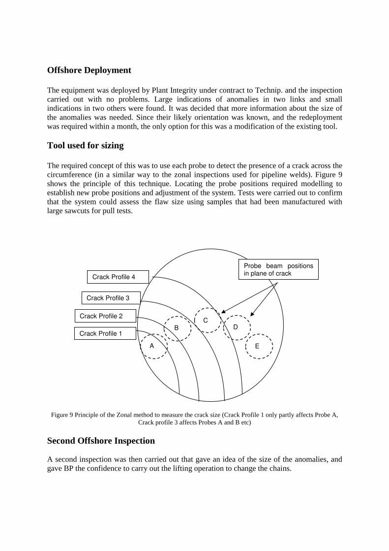
Offshore Deployment The equipment was deployed by Plant Integrity under contract to Technip. and the inspection carried out with no problems. Large indications of anomalies in two links and small indications in two others were found. It was decided that more information about the size of the anomalies was needed. Since their likely orientation was known, and the redeployment was required within a month, the only option for this was a modification of the existing tool. Tool used for sizing The required concept of this was to use each probe to detect the presence of a crack across the circumference (in a similar way to the zonal inspections used for pipeline welds). Figure 9 shows the principle of this technique. Locating the probe positions required modelling to establish new probe positions and adjustment of the system. Tests were carried out to confirm that the system could assess the flaw size using samples that had been manufactured with large sawcuts for pull tests.
Figure 9 Principle of the Zonal method to measure the crack size (Crack Profile 1 only partly affects Probe A, Crack profile 3 affects Probes A and B etc)
Second Offshore Inspection A second inspection was then carried out that gave an idea of the size of the anomalies, and gave BP the confidence to carry out the lifting operation to change the chains.
Crack Profile 1
Crack Profile 2
Crack Profile 3
Crack Profile 4
A
B C
D
E
Probe beam positions in plane of crack
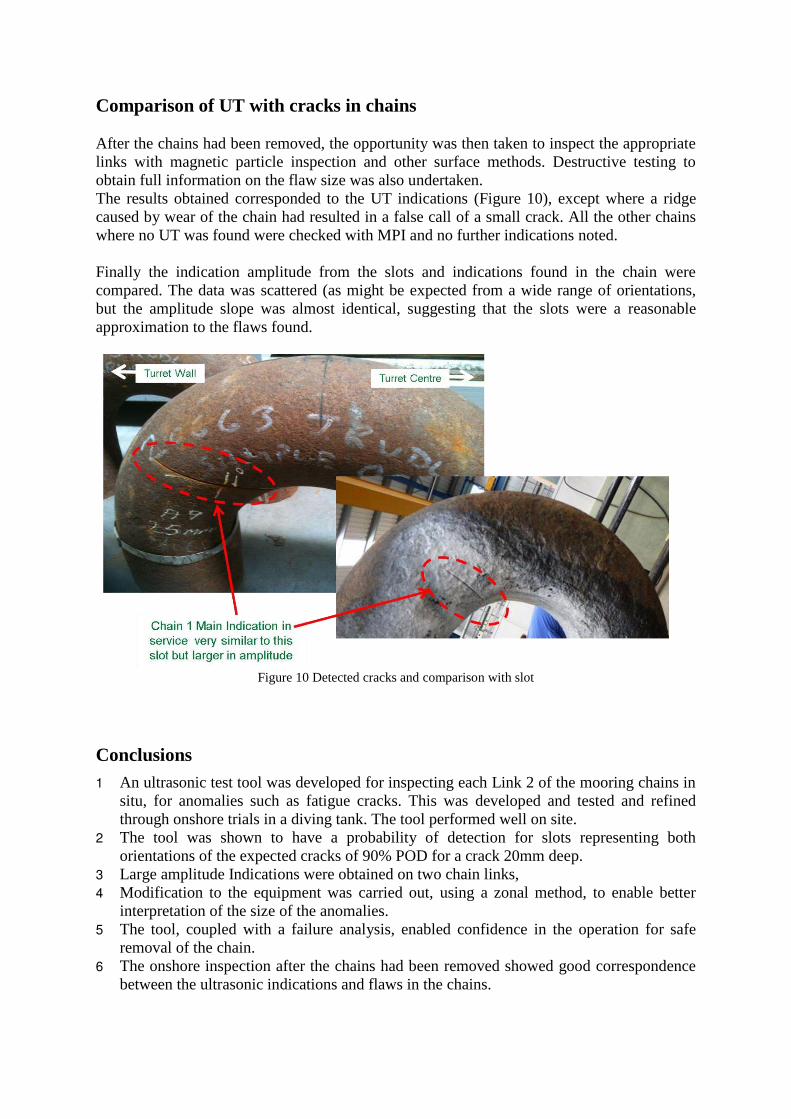
Comparison of UT with cracks in chains After the chains had been removed, the opportunity was then taken to inspect the appropriate links with magnetic particle inspection and other surface methods. Destructive testing to obtain full information on the flaw size was also undertaken. The results obtained corresponded to the UT indications (Figure 10), except where a ridge caused by wear of the chain had resulted in a false call of a small crack. All the other chains where no UT was found were checked with MPI and no further indications noted. Finally the indication amplitude from the slots and indications found in the chain were compared. The data was scattered (as might be expected from a wide range of orientations, but the amplitude slope was almost identical, suggesting that the slots were a reasonable approximation to the flaws found.
Figure 10 Detected cracks and comparison with slot
Conclusions 1 An ultrasonic test tool was developed for inspecting each Link 2 of the mooring chains in
situ, for anomalies such as fatigue cracks. This was developed and tested and refined through onshore trials in a diving tank. The tool performed well on site.
2 The tool was shown to have a probability of detection for slots representing both orientations of the expected cracks of 90% POD for a crack 20mm deep.
3 Large amplitude Indications were obtained on two chain links, 4 Modification to the equipment was carried out, using a zonal method, to enable better
interpretation of the size of the anomalies. 5 The tool, coupled with a failure analysis, enabled confidence in the operation for safe
removal of the chain. 6 The onshore inspection after the chains had been removed showed good correspondence
between the ultrasonic indications and flaws in the chains.
Acknowledgements This was a major inspection and could not have been achieved without significant team effort led by BP (the contribution of Neil Stagg, Alwyn Mcleary and Craig Donaldson, amongst others to facilitate the inspection is particularly acknowledged). The following also contributed significantly to the technical work and support of this project. TWI: Channa Nageswaran, Capucine Carpentier, Dorothee Panggabean, Kim Hayward, Philippe Bastid, Joanna Nicholas, Nigel Lee Plant Integrity: Neil Dodsworth, Graham Edwards, Angela Norrie, Sean Fewell Technip: Peter Dickson, Cameron George and the diving team Phoenix ISL: Karl Quirk, Tony Price, Chris Gregory TWI would like to thank BP for permission to publish this work, .
Reference Schneider C R A and Rudlin J R, 2004: ‘Review of statistical methods used in quantifying NDT reliability’.Insight 46 (2) February

Related Documents