4 Industrial controllers Multi-axis controller V 6 1/100 2011 1 2 3 4 5 7.1 Multi-axis controller left (dir. 1-2, 3-4) 7.2 Multi-axis controller right (dir. 5-6, 7-8) 10 Gate cross-shaped (prohibits diagonal shifting) 11 Gate special-shaped (e.g. H-gate) 20 Control-handle with knob solid 21 Control-handle with latch for mechanical zero interlock 21.1 by lifting 21.2 by lifting, interlocking the gate 21.4 by pushing down 21.5 Mechanical zero interlock with command devices see catalog 1/274 22 Control-handle with dead man’s button 1 NO 23 Control-handle with signal button 1 NO 24 Control-handle with push button 1 NO 25 Control-handle with flat push button 1 NO 26 Control-handle with palm grip B 1 27 Control-handle with palm grip B 1 with push button top 1 NO 28 Control-handle long or short 28.1 -40 mm 28.2 -20 mm 28.3 +20 mm 29 More knobs, grips and T-grips with and without signal devices see catalog 1/270ff 30 Masterswitch (contact set) switching sequence 4-0-4 31 32 Direction 1-2 and 3-4 each 1 masterswitch 33 Switching program according contact-arrangement MS... see catalog 5/001 34 or to your contact-arrangement 35 36 Switching sequence 5-0-5 or 6-0-6 37 Micro changeover contact (MZT 1) positive opening 38 Spring return in 0-position (for each direction) 39 Friction brake adjustable (for each direction) Potentiometer e.t.c. each direction with mounted 40 Wire-wound potentiometer T 130, with centre tap, 1,5 Watt wiper current max. 10 mA resistance 2 x 0,5k P021, 2 x 1k P022, 2 x 2k P023, 2 x 5k P024, 2 x 10k P025 41 Prepared for mounting potentiometer shaft 6 mm adjusting-angle 2 x 150° 42 Prepared for mounting potentiometer e.t.c. adjusting-angle variable. 43 more Potentiometer e.t.c. see catalog 1/240ff 50 Steel sheet housing B 200 masterswitch max. size 04 51 Steel sheet housing B 230 x 340 masterswitch max. size 06 52 More housing see catalog 1/350 60 Indicating labels not engraved with 2 or 4 arrows 61 Engraving, each 10 characters 70 Command and indicating devices see catalog 1/360 960 980 980 1010 960 60 60 50 60 50 100 100 110 110 40 60 290 350 410 470 530 590 110 30 70 1300 1500 V 61 V 61.1 V 62 V 64 V 64.1 L R P PX M MP MN T H D DV B 1 B 1T S3 S5 S8 01 02 03 04 05 06 Z R P (P) (P) B B The multi-axis controller V 6 is a rugged switching device according IEC/EN 60947-5-1 for hoisting applications. The modular design enables the switching device to be used universally. The V 6 is resistant to oil, maritime climate, ozone and UV radiation. Contact complement 2 A 250 V AC 15 or 1 A 24 V DC 13 (standard) or 4 A 250 V AC 15 (special) with positive opening operation Mechanical life 10 million (operating cycles) Permissible ambient temperature Operation -40° C to +60° C Storage -50° C to +80° C Climate resistance Damp heat constant IEC 60068-2-78 Damp heat cyclic IEC 60068-2-30 Degree of protection front IP 54 IEC/EN 60529 Technical data see catalog 5/100 Description data see catalog 5/002 Spindle block with schematic representation of the master controller installation and deflection directions. Version shown for left-hand side installation (right-hand side installation is mirror image). 5 7 8 6 1 3 4 2 Deflection directions designated to DIN 15025 left right 1 1-2 2 1 1-2 2 3-4 1 2 3 4 1 2 1-2 1 3 4 2 3-4 Pos. V 61 V 61.1 V 62 V 64 V 64.1 Weight gramm Type expansion Type Price EURO A... ...P02 C..., P... No. of contacts 2 4 6 8 10 12 2 Type V62L-03ZP+03Z-… 191,- 290,- 234,- 322,- 290,- 38,- 63,- 50,- 63,- 63,- 54,- 54,- 62,- 66,- 24,- 74,- 14,- 59,- 89,- 119,- 149,- 179,- 209,- 34,- 31,- 27,- 27,- 139,- 58,- 129,- 136,- 230,- 9,- 10,- ®

Welcome message from author
This document is posted to help you gain knowledge. Please leave a comment to let me know what you think about it! Share it to your friends and learn new things together.
Transcript
4
Industrial controllersMulti-axis controller V 6
1/100
2011
1
2
3
4
5
7.1 Multi-axis controller left (dir. 1-2, 3-4)
7.2 Multi-axis controller right (dir. 5-6, 7-8)
10 Gate cross-shaped (prohibits diagonal shifting)
11 Gate special-shaped (e.g. H-gate)
20 Control-handle with knob solid
21 Control-handle with latch for mechanical zero interlock
21.1 by lifting
21.2 by lifting, interlocking the gate
21.4 by pushing down
21.5 Mechanical zero interlock with command devices see catalog 1/274
22 Control-handle with dead man’s button 1 NO
23 Control-handle with signal button 1 NO
24 Control-handle with push button 1 NO
25 Control-handle with flat push button 1 NO
26 Control-handle with palm grip B 1
27 Control-handle with palm grip B 1 with push button top 1 NO
28 Control-handle long or short
28.1 -40 mm
28.2 -20 mm
28.3 +20 mm
29 More knobs, grips and T-grips with and without signal devices
see catalog 1/270ff
30 Masterswitch (contact set) switching sequence 4-0-4
31
32 Direction 1-2 and 3-4 each 1 masterswitch
33 Switching program according contact-arrangement MS... see catalog 5/001
34 or to your contact-arrangement
35
36 Switching sequence 5-0-5 or 6-0-6
37 Micro changeover contact (MZT 1) positive opening
38 Spring return in 0-position (for each direction)
39 Friction brake adjustable (for each direction)
Potentiometer e.t.c. each direction with mounted
40 Wire-wound potentiometer T 130, with centre tap,
1,5 Watt wiper current max. 10 mA
resistance 2 x 0,5k P021, 2 x 1k P022, 2 x 2k P023, 2 x 5k P024,
2 x 10k P025
41 Prepared for mounting potentiometer shaft 6 mm adjusting-angle 2 x 150°
42 Prepared for mounting potentiometer e.t.c. adjusting-angle variable.
43 more Potentiometer e.t.c. see catalog 1/240ff
50 Steel sheet housing B 200 masterswitch max. size 04
51 Steel sheet housing B 230 x 340 masterswitch max. size 06
52 More housing see catalog 1/350
60 Indicating labels not engraved with 2 or 4 arrows
61 Engraving, each 10 characters
70 Command and indicating devices see catalog 1/360
960
980
980
1010
960
60
60
50
60
50
100
100
110
110
40
60
290
350
410
470
530
590
110
30
70
1300
1500
V 61
V 61.1
V 62
V 64
V 64.1
L
R
P
PX
M
MP
MN
T
H
D
DV
B 1
B 1T
S3
S5
S8
01
02
03
04
05
06
Z
R
P
(P)
(P)
B
B
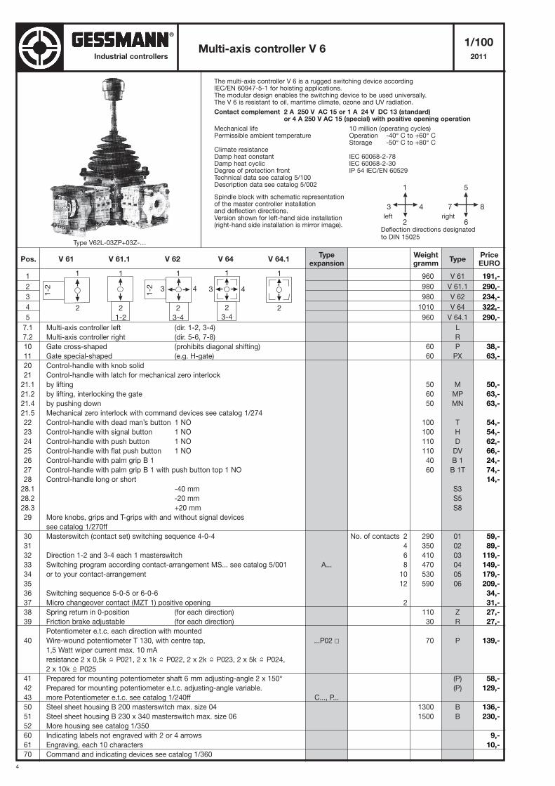
The multi-axis controller V 6 is a rugged switching device accordingIEC/EN 60947-5-1 for hoisting applications.The modular design enables the switching device to be used universally.The V 6 is resistant to oil, maritime climate, ozone and UV radiation.
Contact complement 2 A 250 V AC 15 or 1 A 24 V DC 13 (standard) or 4 A 250 V AC 15 (special) with positive opening operation
Mechanical life 10 million (operating cycles)Permissible ambient temperature Operation -40° C to +60° C
Storage -50° C to +80° CClimate resistanceDamp heat constant IEC 60068-2-78Damp heat cyclic IEC 60068-2-30Degree of protection front IP 54 IEC/EN 60529Technical data see catalog 5/100Description data see catalog 5/002
Spindle block with schematic representationof the master controller installationand deflection directions.Version shown for left-hand side installation(right-hand side installation is mirror image).
5
7 8
6
1
3 4
2Deflection directions designatedto DIN 15025
left right
1
1-2
2
1
1-2
2
3-4
1
2
3 4
1
2
1-2
1
3 4
2
3-4
Pos. V 61 V 61.1 V 62 V 64 V 64.1Weightgramm
Typeexpansion
TypePriceEURO
A...
...P02 �
C..., P...
No. of contacts 2
4
6
8
10
12
2
Type V62L-03ZP+03Z-…
191,-
290,-
234,-
322,-
290,-
38,-
63,-
50,-
63,-
63,-
54,-
54,-
62,-
66,-
24,-
74,-
14,-
59,-
89,-
119,-
149,-
179,-
209,-
34,-
31,-
27,-
27,-
139,-
58,-
129,-
136,-
230,-
9,-
10,-
®
5
Multi-axis controller V 61/101
2011Industrial controllers
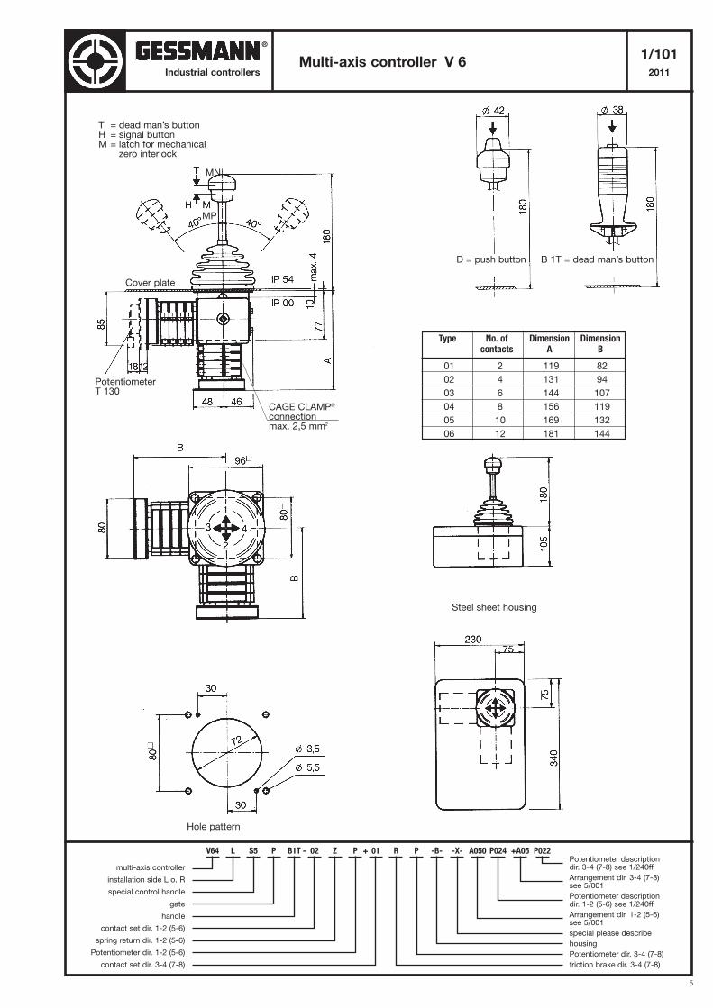
T = dead man’s buttonH = signal buttonM = latch for mechanical
zero interlock
Cover plate
PotentiometerT 130
D = push button
Steel sheet housing
Hole pattern
B 1T = dead man’s button
Type No. of Dimension Dimensioncontacts A B
01 2 119 82
02 4 131 94
03 6 144 107
04 8 156 119
05 10 169 132
06 12 181 144
V64 L S5 P B1T - 02 Z P + 01 R P -B- -X- A050 P024 +A05 P022
multi-axis controller
installation side L o. R
special control handle
gate
handle
contact set dir. 1-2 (5-6)
spring return dir. 1-2 (5-6)
Potentiometer dir. 1-2 (5-6)
contact set dir. 3-4 (7-8)
Potentiometer descriptiondir. 3-4 (7-8) see 1/240ff
Arrangement dir. 3-4 (7-8) see 5/001
Potentiometer descriptiondir. 1-2 (5-6) see 1/240ff
Arrangement dir. 1-2 (5-6) see 5/001
special please describe
housing
Potentiometer dir. 3-4 (7-8)
friction brake dir. 3-4 (7-8)
MN
MP
CAGE CLAMP®
connectionmax. 2,5 mm2
®
6
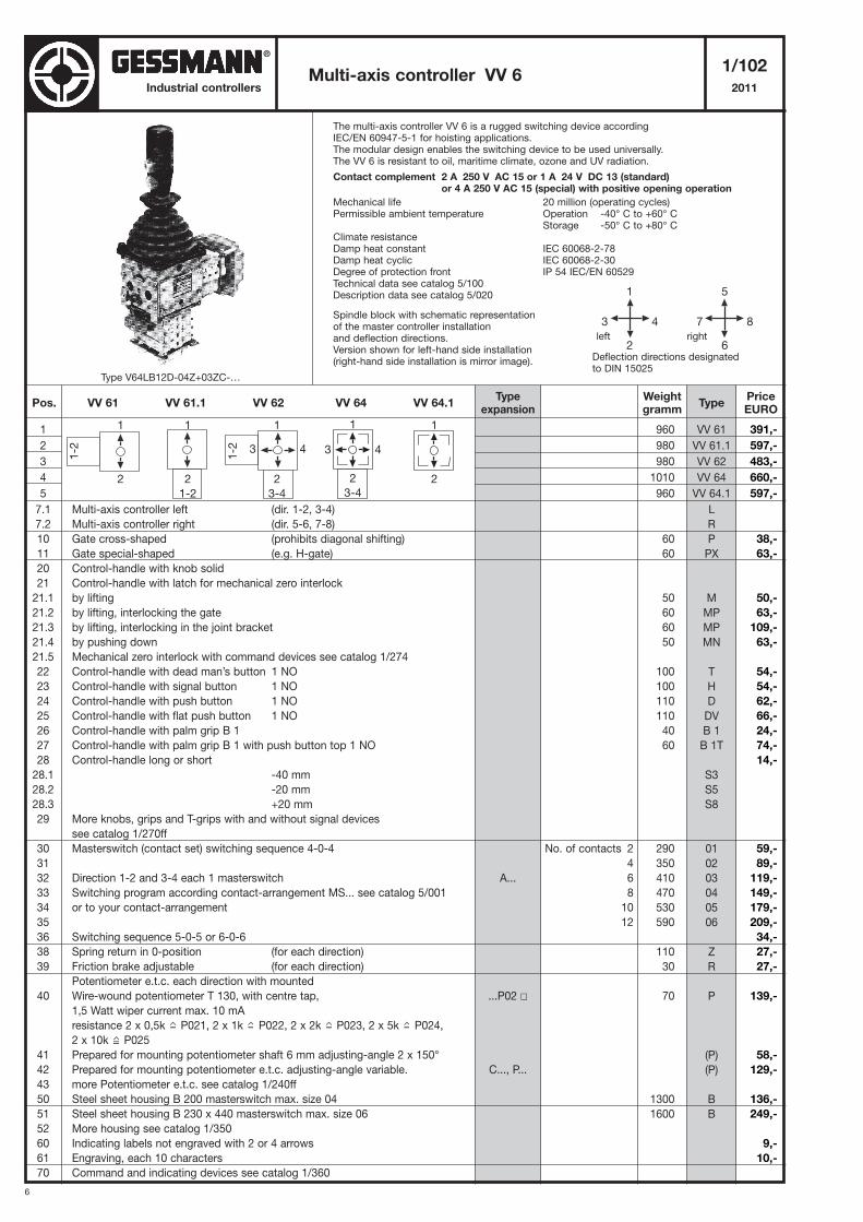
The multi-axis controller VV 6 is a rugged switching device accordingIEC/EN 60947-5-1 for hoisting applications.The modular design enables the switching device to be used universally.The VV 6 is resistant to oil, maritime climate, ozone and UV radiation.
Contact complement 2 A 250 V AC 15 or 1 A 24 V DC 13 (standard) or 4 A 250 V AC 15 (special) with positive opening operation
Mechanical life 20 million (operating cycles)Permissible ambient temperature Operation -40° C to +60° C
Storage -50° C to +80° CClimate resistanceDamp heat constant IEC 60068-2-78Damp heat cyclic IEC 60068-2-30Degree of protection front IP 54 IEC/EN 60529Technical data see catalog 5/100Description data see catalog 5/020
Spindle block with schematic representationof the master controller installationand deflection directions.Version shown for left-hand side installation(right-hand side installation is mirror image).
Multi-axis controller VV 61/102
2011
1
2
3
4
5
7.1 Multi-axis controller left (dir. 1-2, 3-4)
7.2 Multi-axis controller right (dir. 5-6, 7-8)
10 Gate cross-shaped (prohibits diagonal shifting)
11 Gate special-shaped (e.g. H-gate)
20 Control-handle with knob solid
21 Control-handle with latch for mechanical zero interlock
21.1 by lifting
21.2 by lifting, interlocking the gate
21.3 by lifting, interlocking in the joint bracket
21.4 by pushing down
21.5 Mechanical zero interlock with command devices see catalog 1/274
22 Control-handle with dead man’s button 1 NO
23 Control-handle with signal button 1 NO
24 Control-handle with push button 1 NO
25 Control-handle with flat push button 1 NO
26 Control-handle with palm grip B 1
27 Control-handle with palm grip B 1 with push button top 1 NO
28 Control-handle long or short
28.1 -40 mm
28.2 -20 mm
28.3 +20 mm
29 More knobs, grips and T-grips with and without signal devices
see catalog 1/270ff
30 Masterswitch (contact set) switching sequence 4-0-4
31
32 Direction 1-2 and 3-4 each 1 masterswitch
33 Switching program according contact-arrangement MS... see catalog 5/001
34 or to your contact-arrangement
35
36 Switching sequence 5-0-5 or 6-0-6
38 Spring return in 0-position (for each direction)
39 Friction brake adjustable (for each direction)
Potentiometer e.t.c. each direction with mounted
40 Wire-wound potentiometer T 130, with centre tap,
1,5 Watt wiper current max. 10 mA
resistance 2 x 0,5k P021, 2 x 1k P022, 2 x 2k P023, 2 x 5k P024,
2 x 10k P025
41 Prepared for mounting potentiometer shaft 6 mm adjusting-angle 2 x 150°
42 Prepared for mounting potentiometer e.t.c. adjusting-angle variable.
43 more Potentiometer e.t.c. see catalog 1/240ff
50 Steel sheet housing B 200 masterswitch max. size 04
51 Steel sheet housing B 230 x 440 masterswitch max. size 06
52 More housing see catalog 1/350
60 Indicating labels not engraved with 2 or 4 arrows
61 Engraving, each 10 characters
70 Command and indicating devices see catalog 1/360
960
980
980
1010
960
60
60
50
60
60
50
100
100
110
110
40
60
290
350
410
470
530
590
110
30
70
1300
1600
VV 61
VV 61.1
VV 62
VV 64
VV 64.1
L
R
P
PX
M
MP
MP
MN
T
H
D
DV
B 1
B 1T
S3
S5
S8
01
02
03
04
05
06
Z
R
P
(P)
(P)
B
B
Industrial controllers
5
7 8
6
1
3 4
2Deflection directions designatedto DIN 15025
left right
1
1-2
2
1
1-2
2
3-4
1
2
3 4
1
2
1-2
1
3 4
2
3-4
Pos. VV 61 VV 61.1 VV 62 VV 64 VV 64.1Weightgramm
Typeexpansion
TypePriceEURO
A...
...P02 �
C..., P...
No. of contacts 2
4
6
8
10
12
Type V64LB12D-04Z+03ZC-…
391,-
597,-
483,-
660,-
597,-
38,-
63,-
50,-
63,-
109,-
63,-
54,-
54,-
62,-
66,-
24,-
74,-
14,-
59,-
89,-
119,-
149,-
179,-
209,-
34,-
27,-
27,-
139,-
58,-
129,-
136,-
249,-
9,-
10,-
®
7
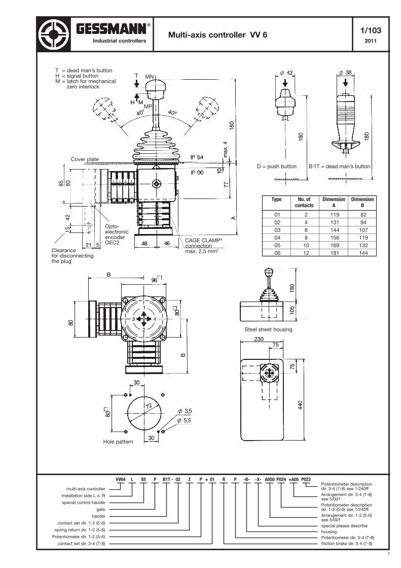
Multi-axis controller VV 61/103
2011Industrial controllers
T = dead man’s buttonH = signal buttonM = latch for mechanical
zero interlock
Cover plate
Clearancefor disconnectingthe plug
D = push button
Steel sheet housing
Hole pattern
B 1T = dead man’s button
Type No. of Dimension Dimensioncontacts A B
01 2 119 82
02 4 131 94
03 6 144 107
04 8 156 119
05 10 169 132
06 12 181 144
Opto-electronicencoderOEC2
VV64 L S5 P B1T - 02 Z P + 01 R P -B- -X- A050 P024 +A05 P022
multi-axis controller
installation side L o. R
special control handle
gate
handle
contact set dir. 1-2 (5-6)
spring return dir. 1-2 (5-6)
Potentiometer dir. 1-2 (5-6)
contact set dir. 3-4 (7-8)
Potentiometer descriptiondir. 3-4 (7-8) see 1/240ff
Arrangement dir. 3-4 (7-8) see 5/001
Potentiometer descriptiondir. 1-2 (5-6) see 1/240ff
Arrangement dir. 1-2 (5-6) see 5/001
special please describe
housing
Potentiometer dir. 3-4 (7-8)
friction brake dir. 3-4 (7-8)
MN
MP
CAGE CLAMP®
connectionmax. 2,5 mm2
®
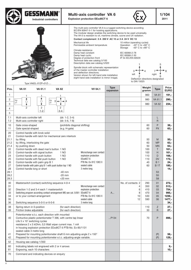
8
Industrial controllers
The multi-axis controller VA 6 is a rugged switching device accordingIEC/EN 60947-5-1 for hoisting applications.The modular design enables the switching device to be used universally.The VA 6 is resistant to oil, maritime climate, ozone and UV radiation.
Contact complement 2 A 250 V AC 15 or 3 A 24 V DC 13
Mechanical life 10 million (operating cycles)Permissible ambient temperature Operation -40° C to +60° C
Storage -50° C to +80° CClimate resistanceDamp heat constant IEC 60068-2-78Damp heat cyclic IEC 60068-2-30Degree of protection front IP 54 IEC/EN 60529Technical data see catalog 5/100Description data see catalog 5/020
Spindle block with schematic representationof the master controller installationand deflection directions.Version shown for left-hand side installation(right-hand side installation is mirror image).
Multi-axis controller VA 6 1/104Explosion protection EExdllCT 6 2011
1
2
3
4
5
7.1 Multi-axis controller left (dir. 1-2, 3-4)
7.2 Multi-axis controller right (dir. 5-6, 7-8)
10 Gate cross-shaped (prohibits diagonal shifting)
11 Gate special-shaped (e.g. H-gate)
20 Control-handle with knob solid
21 Control-handle with latch for mechanical zero interlock
21.1 by lifting
21.2 by lifting, interlocking the gate
21.4 by pushing down
22 Control-handle with dead man’s button 1 NO
23 Control-handle with signal button 1 NO
24 Control-handle with push button 1 NO
25 Control-handle with flat push button 1 NO
26 Control-handle with palm grip B 1
27 Control-handle with palm grip B 1 with push button top 1 NO
28 Control-handle long or short
28.1 -40 mm
28.2 -20 mm
28.3 +20 mm
30 Masterswitch (contact) switching sequence 4-0-4
31
32 Direction 1-2 and 3-4 each 1 masterswitch
33 Switching program according contact-arrangement MS see cat. 5/001
34 or to your contact-arrangement
35
36 Switching sequence 5-0-5 or 6-0-6
38 Spring return in 0-position (for each direction)
39 Friction brake adjustable (for each direction)
Potentiometer e.t.c. each direction with mounted
40 Contuctive plastic potentiometer T 396, with centre tap linear
Life 5 x 10⁷ switching cycles
resistance 2 x 5 kOhm, 0,5 Watt wiper current max. 1 mA
in housing explosion protection EExdllCT 6 PTB-No. Ex-85/1131
sealed cable 3 metre long
41 Prepared for mounting potentiometer shaft 6 mm adjusting-angle 2 x 150°
42 Prepared for mounting potentiometer e.t.c. adjusting-angle variable.
52 Housing see catalog 1/350
60 Indicating labels not engraved with 2 or 4 arrows
61 Engraving, each 10 characters
70 Command and indicating devices on enquiry
960
980
980
60
60
50
60
50
100
100
110
110
40
60
290
350
410
470
530
590
110
30
70
VA 61
VA 61.1
VA 62
L
R
P
PX
M
MP
MN
T
H
D
DV
B 1
B 1T
S3
S5
S8
01
02
03
04
05
06
Z
R
P
(P)
(P)
5
7 8
6
1
3 4
2Deflection directions designatedto DIN 15025
left right
Microchange over contact
explosion protection
EExdllCT 6
PTB No. Ex-91C 1083 X
sealed cable
3 metre long
Microchange over contact
explosion protection
EExdllCT 6
PTB No. Ex-91C 1083 X
sealed cable
3 metre long
Pos. VA 61 VA 61.1 VA 62 VV 64.1Weightgramm
Typeexpansion
TypePriceEURO
A...
...P134
No. of contacts 2
4
6
8
10
12
1
1-2
2
1
1-2
2
3-4
3 4
1
2
1-2
Type VA62L-01ZP+01Z-…
191,-
290,-
234,-
38,-
63,-
50,-
63,-
63,-
161,-
161,-
166,-
172,-
24,-
180,-
14,-
272,-
513,-
754,-
995,-
1236,-
1477,-
34,-
27,-
27,-
898,-
58,-
129,-
9,-
10,-
®
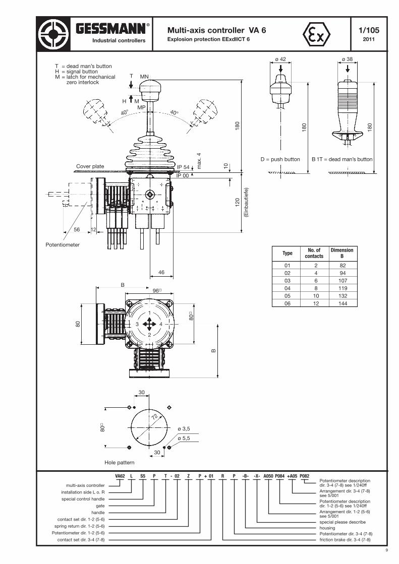
9
Multi-axis controller VA 6 1/105Explosion protection EExdllCT 6 2011Industrial controllers
T = dead man’s buttonH = signal buttonM = latch for mechanical
zero interlock
Cover plate
Potentiometer
D = push button
Hole pattern
B 1T = dead man’s button
TypeNo. of Dimension
contacts B
01 2 82
02 4 94
03 6 107
04 8 119
05 10 132
06 12 144
T
H M
40° 40°
180
(Einbautiefe)
120
46
IP 00
IP 54 10
max. 4
56 12
180
180
ø 42 ø 38
B96�
80
80
�
B
30
30
80
�
72
ø 3,5
ø 5,5
3
1
2
4
VA62 L S5 P T - 02 Z P + 01 R P -B- -X- A050 P084 +A05 P082
multi-axis controller
installation side L o. R
special control handle
gate
handle
contact set dir. 1-2 (5-6)
spring return dir. 1-2 (5-6)
Potentiometer dir. 1-2 (5-6)
contact set dir. 3-4 (7-8)
Potentiometer descriptiondir. 3-4 (7-8) see 1/240ff
Arrangement dir. 3-4 (7-8) see 5/001
Potentiometer descriptiondir. 1-2 (5-6) see 1/240ff
Arrangement dir. 1-2 (5-6) see 5/001
special please describe
housing
Potentiometer dir. 3-4 (7-8)
friction brake dir. 3-4 (7-8)
MN
MP
®
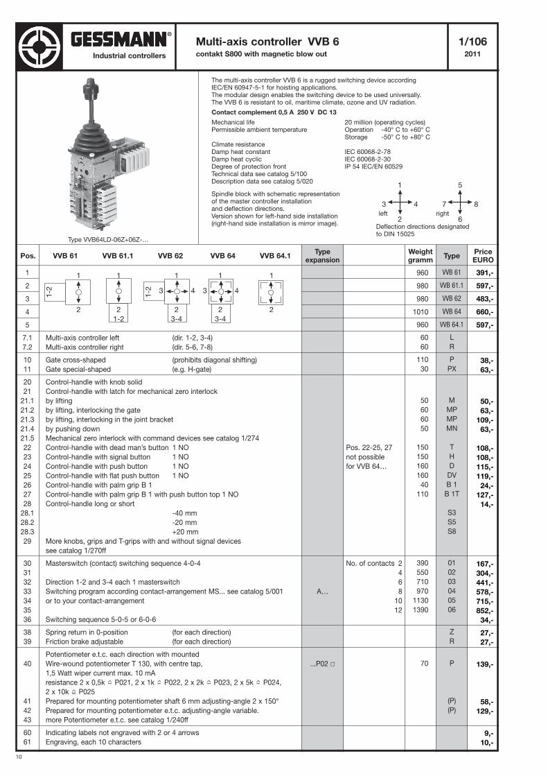
10
Industrial controllers
Multi-axis controller VVB 6 1/106contakt S800 with magnetic blow out 2011
1
2
3
4
5
7.1 Multi-axis controller left (dir. 1-2, 3-4)
7.2 Multi-axis controller right (dir. 5-6, 7-8)
10 Gate cross-shaped (prohibits diagonal shifting)
11 Gate special-shaped (e.g. H-gate)
20 Control-handle with knob solid
21 Control-handle with latch for mechanical zero interlock
21.1 by lifting
21.2 by lifting, interlocking the gate
21.3 by lifting, interlocking in the joint bracket
21.4 by pushing down
21.5 Mechanical zero interlock with command devices see catalog 1/274
22 Control-handle with dead man’s button 1 NO
23 Control-handle with signal button 1 NO
24 Control-handle with push button 1 NO
25 Control-handle with flat push button 1 NO
26 Control-handle with palm grip B 1
27 Control-handle with palm grip B 1 with push button top 1 NO
28 Control-handle long or short
28.1 -40 mm
28.2 -20 mm
28.3 +20 mm
29 More knobs, grips and T-grips with and without signal devices
see catalog 1/270ff
30 Masterswitch (contact) switching sequence 4-0-4
31
32 Direction 1-2 and 3-4 each 1 masterswitch
33 Switching program according contact-arrangement MS... see catalog 5/001
34 or to your contact-arrangement
35
36 Switching sequence 5-0-5 or 6-0-6
38 Spring return in 0-position (for each direction)
39 Friction brake adjustable (for each direction)
Potentiometer e.t.c. each direction with mounted
40 Wire-wound potentiometer T 130, with centre tap,
1,5 Watt wiper current max. 10 mA
resistance 2 x 0,5k P021, 2 x 1k P022, 2 x 2k P023, 2 x 5k P024,
2 x 10k P025
41 Prepared for mounting potentiometer shaft 6 mm adjusting-angle 2 x 150°
42 Prepared for mounting potentiometer e.t.c. adjusting-angle variable.
43 more Potentiometer e.t.c. see catalog 1/240ff
60 Indicating labels not engraved with 2 or 4 arrows
61 Engraving, each 10 characters
960
980
980
1010
960
60
60
110
30
50
60
60
50
150
150
160
160
40
110
390
550
710
970
1130
1390
70
VVB 61
VVB 61.1
VVB 62
VVB 64
VVB 64.1
L
R
P
PX
M
MP
MP
MN
T
H
D
DV
B 1
B 1T
S3
S5
S8
01
02
03
04
05
06
Z
R
P
(P)
(P)
Pos. VVB 61 VVB 61.1 VVB 62 VVB 64 VVB 64.1Weightgramm
Typeexpansion
TypePriceEURO
A…
...P02 �
Pos. 22-25, 27
not possible
for VVB 64…
No. of contacts 2
4
6
8
10
12
The multi-axis controller VVB 6 is a rugged switching device accordingIEC/EN 60947-5-1 for hoisting applications.The modular design enables the switching device to be used universally.The VVB 6 is resistant to oil, maritime climate, ozone and UV radiation.
Contact complement 0,5 A 250 V DC 13
Mechanical life 20 million (operating cycles)Permissible ambient temperature Operation -40° C to +60° C
Storage -50° C to +80° CClimate resistanceDamp heat constant IEC 60068-2-78Damp heat cyclic IEC 60068-2-30Degree of protection front IP 54 IEC/EN 60529Technical data see catalog 5/100Description data see catalog 5/020
Spindle block with schematic representationof the master controller installationand deflection directions.Version shown for left-hand side installation(right-hand side installation is mirror image).
5
7 8
6
1
3 4
2Deflection directions designatedto DIN 15025
left right
1
1-2
2
1
2
1
1-2
2
3-4
3 4
1
2
3-4
3 4
1
2
1-2
Type VVB64LD-06Z+06Z-…
391,-
597,-
483,-
660,-
597,-
38,-
63,-
50,-
63,-
109,-
63,-
108,-
108,-
115,-
119,-
24,-
127,-
14,-
167,-
304,-
441,-
578,-
715,-
852,-
34,-
27,-
27,-
139,-
58,-
129,-
9,-
10,-
®
11
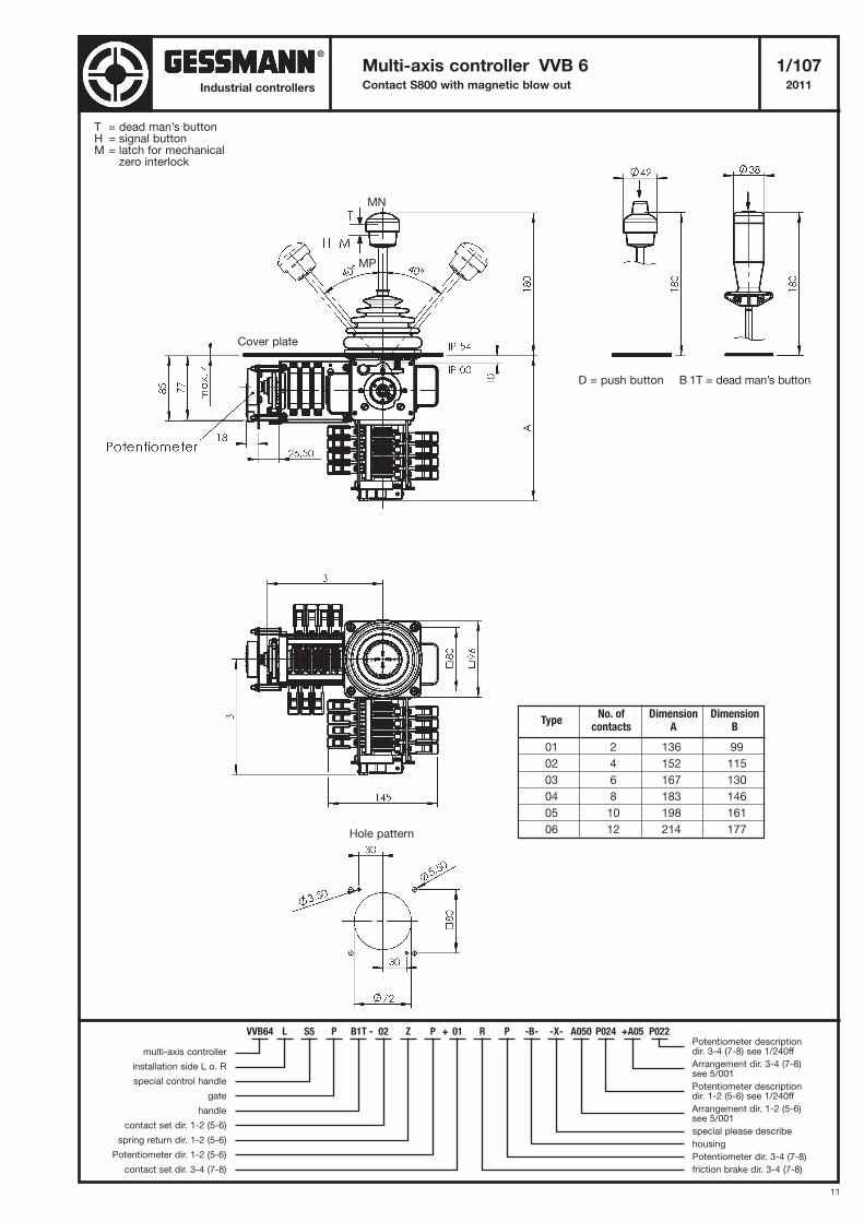
Multi-axis controller VVB 6 1/107Contact S800 with magnetic blow out 2011Industrial controllers
T = dead man’s buttonH = signal buttonM = latch for mechanical
zero interlock
D = push button B 1T = dead man’s button
Cover plate
Hole pattern
TypeNo. of Dimension Dimension
contacts A B
01 2 136 99
02 4 152 115
03 6 167 130
04 8 183 146
05 10 198 161
06 12 214 177
VVB64 L S5 P B1T - 02 Z P + 01 R P -B- -X- A050 P024 +A05 P022
multi-axis controller
installation side L o. R
special control handle
gate
handle
contact set dir. 1-2 (5-6)
spring return dir. 1-2 (5-6)
Potentiometer dir. 1-2 (5-6)
contact set dir. 3-4 (7-8)
Potentiometer descriptiondir. 3-4 (7-8) see 1/240ff
Arrangement dir. 3-4 (7-8) see 5/001
Potentiometer descriptiondir. 1-2 (5-6) see 1/240ff
Arrangement dir. 1-2 (5-6) see 5/001
special please describe
housing
Potentiometer dir. 3-4 (7-8)
friction brake dir. 3-4 (7-8)
MN
MP
®
12
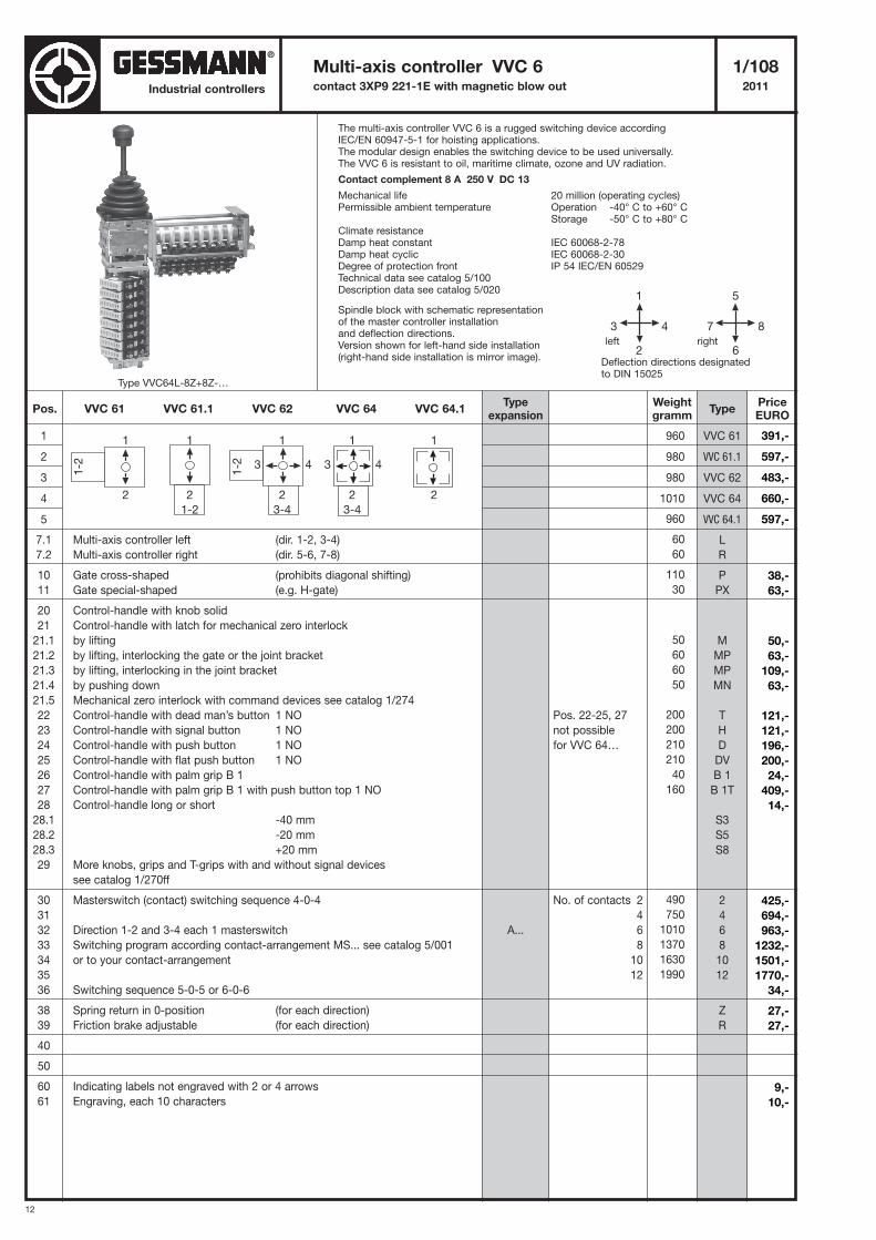
Industrial controllers
Multi-axis controller VVC 6 1/108contact 3XP9 221-1E with magnetic blow out 2011
1
2
3
4
5
7.1 Multi-axis controller left (dir. 1-2, 3-4)
7.2 Multi-axis controller right (dir. 5-6, 7-8)
10 Gate cross-shaped (prohibits diagonal shifting)
11 Gate special-shaped (e.g. H-gate)
20 Control-handle with knob solid
21 Control-handle with latch for mechanical zero interlock
21.1 by lifting
21.2 by lifting, interlocking the gate or the joint bracket
21.3 by lifting, interlocking in the joint bracket
21.4 by pushing down
21.5 Mechanical zero interlock with command devices see catalog 1/274
22 Control-handle with dead man’s button 1 NO
23 Control-handle with signal button 1 NO
24 Control-handle with push button 1 NO
25 Control-handle with flat push button 1 NO
26 Control-handle with palm grip B 1
27 Control-handle with palm grip B 1 with push button top 1 NO
28 Control-handle long or short
28.1 -40 mm
28.2 -20 mm
28.3 +20 mm
29 More knobs, grips and T-grips with and without signal devices
see catalog 1/270ff
30 Masterswitch (contact) switching sequence 4-0-4
31
32 Direction 1-2 and 3-4 each 1 masterswitch
33 Switching program according contact-arrangement MS... see catalog 5/001
34 or to your contact-arrangement
35
36 Switching sequence 5-0-5 or 6-0-6
38 Spring return in 0-position (for each direction)
39 Friction brake adjustable (for each direction)
40
50
60 Indicating labels not engraved with 2 or 4 arrows
61 Engraving, each 10 characters
960
980
980
1010
960
60
60
110
30
50
60
60
50
200
200
210
210
40
160
490
750
1010
1370
1630
1990
VVC 61
VVC 61.1
VVC 62
VVC 64
VVC 64.1
L
R
P
PX
M
MP
MP
MN
T
H
D
DV
B 1
B 1T
S3
S5
S8
2
4
6
8
10
12
Z
R
Pos. VVC 61 VVC 61.1 VVC 62 VVC 64 VVC 64.1Weightgramm
Typeexpansion
TypePriceEURO
A...
Pos. 22-25, 27
not possible
for VVC 64…
No. of contacts 2
4
6
8
10
12
The multi-axis controller VVC 6 is a rugged switching device accordingIEC/EN 60947-5-1 for hoisting applications.The modular design enables the switching device to be used universally.The VVC 6 is resistant to oil, maritime climate, ozone and UV radiation.
Contact complement 8 A 250 V DC 13
Mechanical life 20 million (operating cycles)Permissible ambient temperature Operation -40° C to +60° C
Storage -50° C to +80° CClimate resistanceDamp heat constant IEC 60068-2-78Damp heat cyclic IEC 60068-2-30Degree of protection front IP 54 IEC/EN 60529Technical data see catalog 5/100Description data see catalog 5/020
Spindle block with schematic representationof the master controller installationand deflection directions.Version shown for left-hand side installation(right-hand side installation is mirror image).
5
7 8
6
1
3 4
2Deflection directions designatedto DIN 15025
left right
1
1-2
2
1
2
1
1-2
2
3-4
3 4
1
2
3-4
3 4
1
2
1-2
Type VVC64L-8Z+8Z-…
391,-
597,-
483,-
660,-
597,-
38,-
63,-
50,-
63,-
109,-
63,-
121,-
121,-
196,-
200,-
24,-
409,-
14,-
425,-
694,-
963,-
1232,-
1501,-
1770,-
34,-
27,-
27,-
9,-
10,-
®
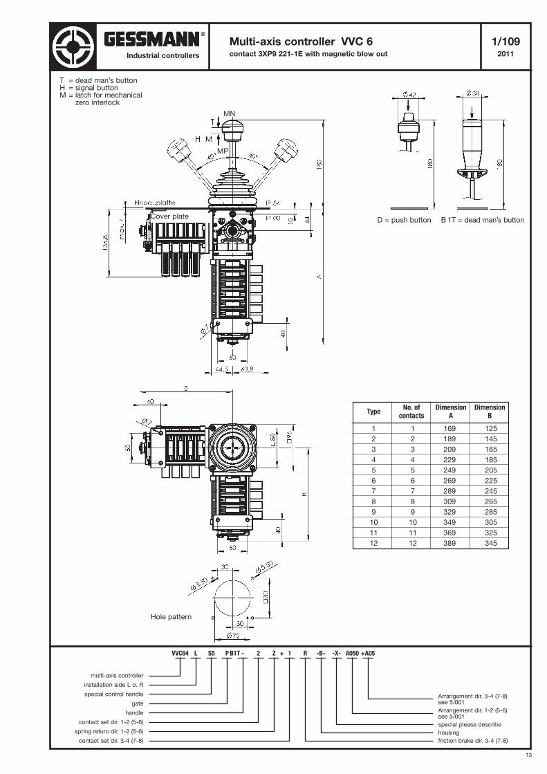
13
Multi-axis controller VVC 6 1/109contact 3XP9 221-1E with magnetic blow out 2011Industrial controllers
T = dead man’s buttonH = signal buttonM = latch for mechanical
zero interlock
D = push button B 1T = dead man’s buttonCover plate
Hole pattern
TypeNo. of Dimension Dimension
contacts A B
1 1 169 125
2 2 189 145
3 3 209 165
4 4 229 185
5 5 249 205
6 6 269 225
7 7 289 245
8 8 309 265
9 9 329 285
10 10 349 305
11 11 369 325
12 12 389 345
VVC64 L S5 P B1T - 2 Z + 1 R -B- -X- A050 +A05
multi-axis controller
installation side L o. R
special control handle
gate
handle
contact set dir. 1-2 (5-6)
spring return dir. 1-2 (5-6)
contact set dir. 3-4 (7-8)
Arrangement dir. 3-4 (7-8) see 5/001
Arrangement dir. 1-2 (5-6) see 5/001
special please describe
housing
friction brake dir. 3-4 (7-8)
MN
MP
®
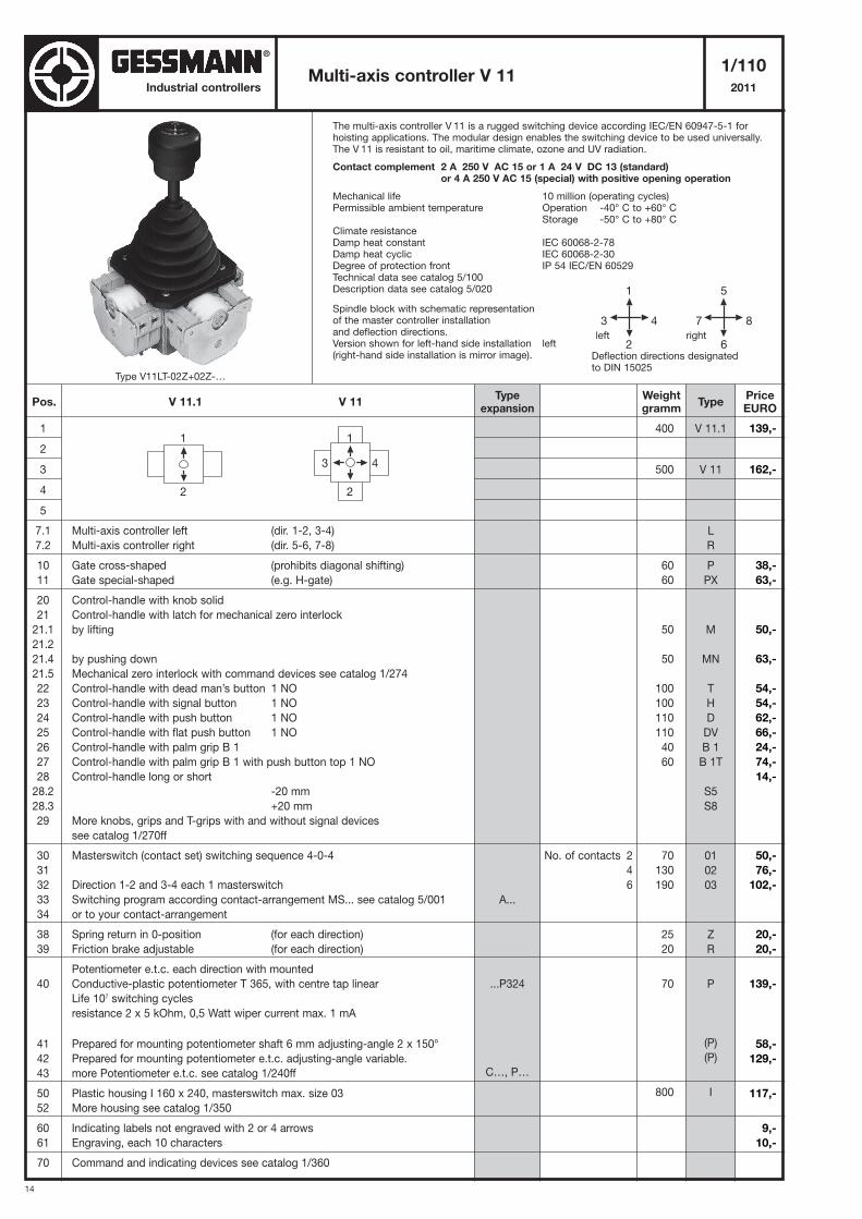
14
Industrial controllers
The multi-axis controller V 11 is a rugged switching device according IEC/EN 60947-5-1 forhoisting applications. The modular design enables the switching device to be used universally.The V 11 is resistant to oil, maritime climate, ozone and UV radiation.
Contact complement 2 A 250 V AC 15 or 1 A 24 V DC 13 (standard)or 4 A 250 V AC 15 (special) with positive opening operation
Mechanical life 10 million (operating cycles)Permissible ambient temperature Operation -40° C to +60° C
Storage -50° C to +80° CClimate resistanceDamp heat constant IEC 60068-2-78Damp heat cyclic IEC 60068-2-30Degree of protection front IP 54 IEC/EN 60529Technical data see catalog 5/100Description data see catalog 5/020
Spindle block with schematic representationof the master controller installationand deflection directions.Version shown for left-hand side installation left(right-hand side installation is mirror image).
Multi-axis controller V 111/110
2011
1
2
3
4
5
7.1 Multi-axis controller left (dir. 1-2, 3-4)
7.2 Multi-axis controller right (dir. 5-6, 7-8)
10 Gate cross-shaped (prohibits diagonal shifting)
11 Gate special-shaped (e.g. H-gate)
20 Control-handle with knob solid
21 Control-handle with latch for mechanical zero interlock
21.1 by lifting
21.2
21.4 by pushing down
21.5 Mechanical zero interlock with command devices see catalog 1/274
22 Control-handle with dead man’s button 1 NO
23 Control-handle with signal button 1 NO
24 Control-handle with push button 1 NO
25 Control-handle with flat push button 1 NO
26 Control-handle with palm grip B 1
27 Control-handle with palm grip B 1 with push button top 1 NO
28 Control-handle long or short
28.2 -20 mm
28.3 +20 mm
29 More knobs, grips and T-grips with and without signal devices
see catalog 1/270ff
30 Masterswitch (contact set) switching sequence 4-0-4
31
32 Direction 1-2 and 3-4 each 1 masterswitch
33 Switching program according contact-arrangement MS... see catalog 5/001
34 or to your contact-arrangement
38 Spring return in 0-position (for each direction)
39 Friction brake adjustable (for each direction)
Potentiometer e.t.c. each direction with mounted
40 Conductive-plastic potentiometer T 365, with centre tap linear
Life 107 switching cycles
resistance 2 x 5 kOhm, 0,5 Watt wiper current max. 1 mA
41 Prepared for mounting potentiometer shaft 6 mm adjusting-angle 2 x 150°
42 Prepared for mounting potentiometer e.t.c. adjusting-angle variable.
43 more Potentiometer e.t.c. see catalog 1/240ff
50 Plastic housing I 160 x 240, masterswitch max. size 03
52 More housing see catalog 1/350
60 Indicating labels not engraved with 2 or 4 arrows
61 Engraving, each 10 characters
70 Command and indicating devices see catalog 1/360
400
500
60
60
50
50
100
100
110
110
40
60
70
130
190
25
20
70
800
V 11.1
V 11
L
R
P
PX
M
MN
T
H
D
DV
B 1
B 1T
S5
S8
01
02
03
Z
R
P
(P)
(P)
I
5
7 8
6
1
3 4
2Deflection directions designatedto DIN 15025
left right
Pos. V 11.1 V 11Weightgramm
Typeexpansion
TypePriceEURO
A...
...P324
C…, P…
No. of contacts 2
4
6
1
2
1
3 4
2
Type V11LT-02Z+02Z-…
139,-
162,-
38,-
63,-
50,-
63,-
54,-
54,-
62,-
66,-
24,-
74,-
14,-
50,-
76,-
102,-
20,-
20,-
139,-
58,-
129,-
117,-
9,-
10,-
®
15
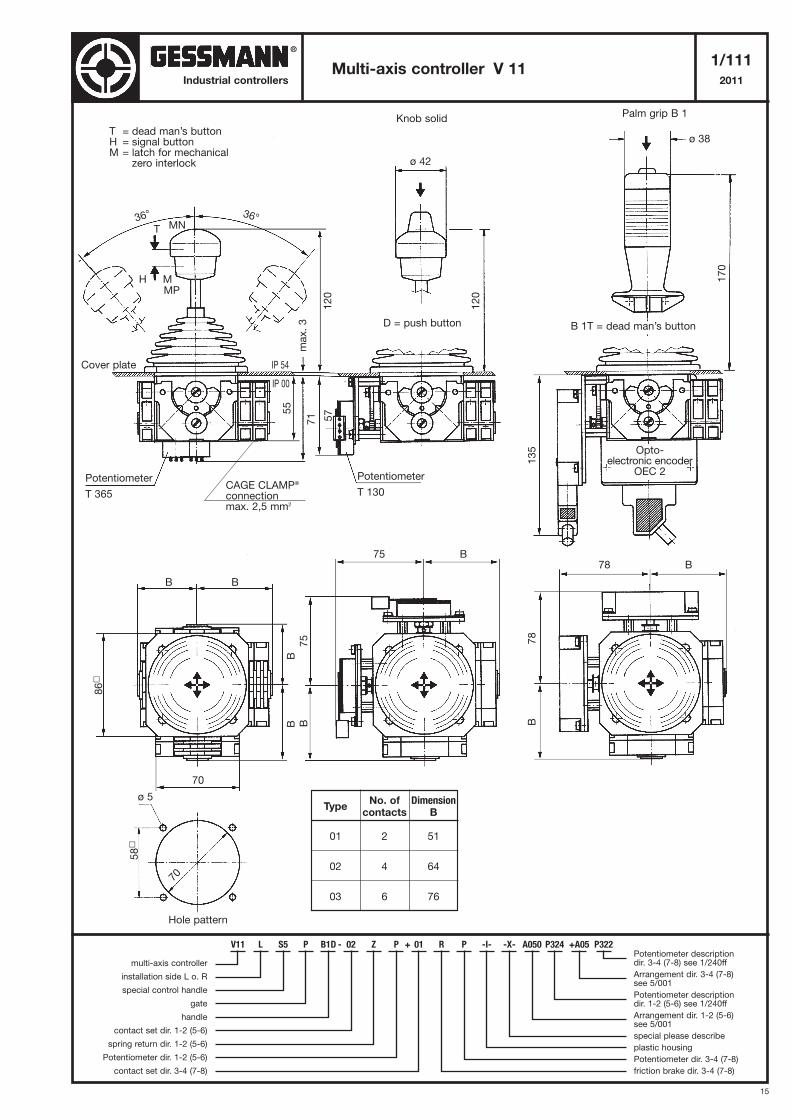
Multi-axis controller V 111/111
2011Industrial controllers
T = dead man’s buttonH = signal buttonM = latch for mechanical
zero interlock
Potentiometer
T 365
Opto-electronic encoder
OEC 2
78 B75 B
B78
B75
BB
135
86
�
58
�
57
7155
Potentiometer
T 130
Knob solidPalm grip B 1
TypeNo. of Dimension
contacts B
01 2 51
02 4 64
03 6 76
Cover plate
D = push button B 1T = dead man’s button
T
H M
36° 36°
IP 00
IP 54
max. 3
120
120
170
ø 42
ø 38
B B
70
ø 5
Hole pattern
70
V11 L S5 P B1D - 02 Z P + 01 R P -I- -X- A050 P324 +A05 P322
multi-axis controller
installation side L o. R
special control handle
gate
handle
contact set dir. 1-2 (5-6)
spring return dir. 1-2 (5-6)
Potentiometer dir. 1-2 (5-6)
contact set dir. 3-4 (7-8)
Potentiometer descriptiondir. 3-4 (7-8) see 1/240ff
Arrangement dir. 3-4 (7-8) see 5/001
Potentiometer descriptiondir. 1-2 (5-6) see 1/240ff
Arrangement dir. 1-2 (5-6) see 5/001
special please describe
plastic housing
Potentiometer dir. 3-4 (7-8)
friction brake dir. 3-4 (7-8)
MN
MP
CAGE CLAMP®
connectionmax. 2,5 mm2
®
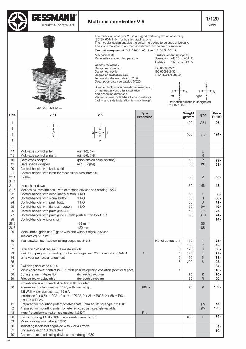
16
Industrial controllers
The multi-axis controller V 5 is a rugged switching device accordingIEC/EN 60947-5-1 for hoisting applications.The modular design enables the switching device to be used universally.The V 5 is resistant to oil, maritime climate, ozone and UV radiation.
Contact complement 2 A 250 V AC 15 or 3 A 24 V DC 13
Mechanical life 6 million (operating cycles)Permissible ambient temperature Operation -40° C to +60° C
Storage -50° C to +80° CClimate resistanceDamp heat constant IEC 60068-2-78Damp heat cyclic IEC 60068-2-30Degree of protection front IP 54 IEC/EN 60529Technical data see catalog 5/100Description data see catalog 5/020
Spindle block with schematic representationof the master controller installationand deflection directions.Version shown for left-hand side installation(right-hand side installation is mirror image).
Multi-axis controller V 51/120
2011
1
2
3
4
5
7.1 Multi-axis controller left (dir. 1-2, 3-4)
7.2 Multi-axis controller right (dir. 5-6, 7-8)
10 Gate cross-shaped (prohibits diagonal shifting)
11 Gate special-shaped (e.g. H-gate)
20 Control-handle with knob solid
21 Control-handle with latch for mechanical zero interlock
21.1 by lifting
21.2
21.4 by pushing down
21.5 Mechanical zero interlock with command devices see catalog 1/274
22 Control-handle with dead man’s button 1 NO
23 Control-handle with signal button 1 NO
24 Control-handle with push button 1 NO
25 Control-handle with flat push button 1 NO
26 Control-handle with palm grip B 5
27 Control-handle with palm grip B 5 with push button top 1 NO
28 Control-handle long or short
28.2 -20 mm
28.3 +20 mm
29 More knobs, grips and T-grips with and without signal devices
see catalog 1/270ff
30 Masterswitch (contact) switching sequence 3-0-3
31
32 Direction 1-2 and 3-4 each 1 masterswitch
33 Switching program according contact-arrangement MS... see catalog 5/001
34 or to your contact-arrangement
35
36 Switching sequence 4-0-4
37 Micro changeover contact (MZT 1) with positive opening operation (additional price)
38 Spring return in 0-position (for each direction)
39 Friction brake adjustable (for each direction)
Potentiometer e.t.c. each direction with mounted
40 Wire-wound potentiometer T 130, with centre tap,
1,5 Watt wiper current max. 10 mA
resistance 2 x 0,5k P021, 2 x 1k P022, 2 x 2k P023, 2 x 5k P024,
2 x 10k P025
41 Prepared for mounting potentiometer shaft 6 mm adjusting-angle 2 x 150°
42 Prepared for mounting potentiometer e.t.c. adjusting-angle variable.
43 more Potentiometer e.t.c. see catalog 1/240ff
50 Plastic housing I 120 x 160, masterswitch max. size 6
52 More housing see catalog 1/350
60 Indicating labels not engraved with 2 or 4 arrows
61 Engraving, each 10 characters
70 Command and indicating devices see catalog 1/360
V 51
V 5
L
R
P
PX
M
MN
T
H
D
DV
B 5
B 5T
S5
S8
1
2
3
4
5
6
Z
R
P
(P)
(P)
I
5
7 8
6
1
3 4
2Deflection directions designatedto DIN 15025
left right
Pos. V 51 V 5Weightgramm
Typeexpansion
TypePriceEURO
A...
...P02 k
P…
No. of contacts 1
2
3
4
5
6
1
1
2
1
3 4
2
400
500
50
50
50
50
50
50
60
60
40
60
150
160
170
180
190
200
25
30
70
600
Type V5LT-4Z+4Z-…
106,-
124,-
29,-
63,-
36,-
48,-
38,-
38,-
41,-
46,-
24,-
74,-
14,-
28,-
43,-
58,-
73,-
88,-
103,-
34,-
13,-
20,-
20,-
139,-
58,-
129,-
79,-
9,-
10,-
®
17
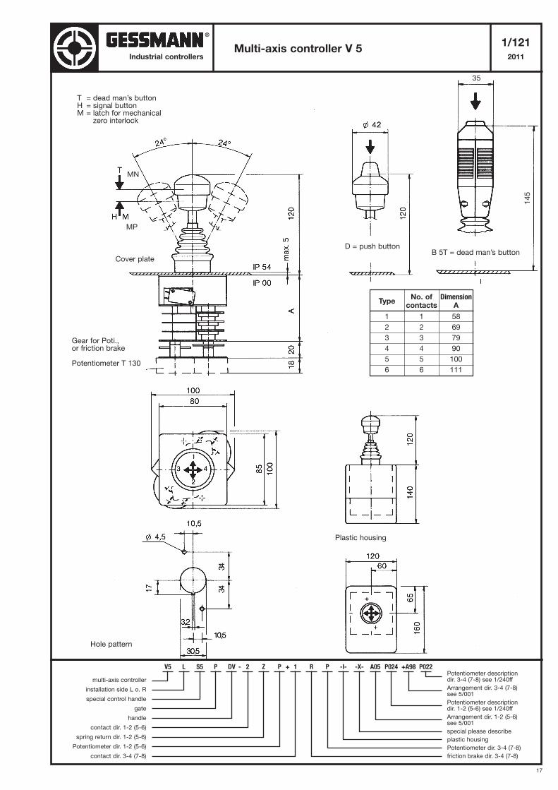
Multi-axis controller V 51/121
2011Industrial controllers
T = dead man’s buttonH = signal buttonM = latch for mechanical
zero interlock
Cover plate
Gear for Poti.,or friction brake
Potentiometer T 130
D = push button
Hole pattern
Plastic housing
B 5T = dead man’s button
TypeNo. of Dimension
contacts A
1 1 58
2 2 69
3 3 79
4 4 90
5 5 100
6 6 111
35
145
V5 L S5 P DV - 2 Z P + 1 R P -I- -X- A05 P024 +A98 P022
multi-axis controller
installation side L o. R
special control handle
gate
handle
contact dir. 1-2 (5-6)
spring return dir. 1-2 (5-6)
Potentiometer dir. 1-2 (5-6)
contact dir. 3-4 (7-8)
Potentiometer descriptiondir. 3-4 (7-8) see 1/240ff
Arrangement dir. 3-4 (7-8) see 5/001
Potentiometer descriptiondir. 1-2 (5-6) see 1/240ff
Arrangement dir. 1-2 (5-6) see 5/001
special please describe
plastic housing
Potentiometer dir. 3-4 (7-8)
friction brake dir. 3-4 (7-8)
MN
MP
®
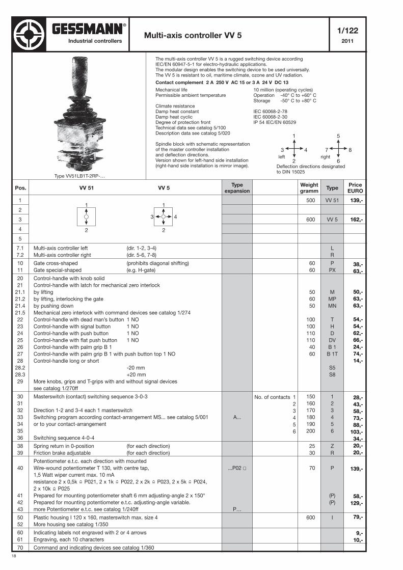
18
Industrial controllers
The multi-axis controller VV 5 is a rugged switching device accordingIEC/EN 60947-5-1 for electro-hydraulic applications.The modular design enables the switching device to be used universally.The VV 5 is resistant to oil, maritime climate, ozone and UV radiation.
Contact complement 2 A 250 V AC 15 or 3 A 24 V DC 13
Mechanical life 10 million (operating cycles)Permissible ambient temperature Operation -40° C to +60° C
Storage -50° C to +80° CClimate resistanceDamp heat constant IEC 60068-2-78Damp heat cyclic IEC 60068-2-30Degree of protection front IP 54 IEC/EN 60529Technical data see catalog 5/100Description data see catalog 5/020
Spindle block with schematic representationof the master controller installationand deflection directions.Version shown for left-hand side installation(right-hand side installation is mirror image).
Multi-axis controller VV 51/122
2011
1
2
3
4
5
7.1 Multi-axis controller left (dir. 1-2, 3-4)
7.2 Multi-axis controller right (dir. 5-6, 7-8)
10 Gate cross-shaped (prohibits diagonal shifting)
11 Gate special-shaped (e.g. H-gate)
20 Control-handle with knob solid
21 Control-handle with latch for mechanical zero interlock
21.1 by lifting
21.2 by lifting, interlocking the gate
21.4 by pushing down
21.5 Mechanical zero interlock with command devices see catalog 1/274
22 Control-handle with dead man’s button 1 NO
23 Control-handle with signal button 1 NO
24 Control-handle with push button 1 NO
25 Control-handle with flat push button 1 NO
26 Control-handle with palm grip B 1
27 Control-handle with palm grip B 1 with push button top 1 NO
28 Control-handle long or short
28.2 -20 mm
28.3 +20 mm
29 More knobs, grips and T-grips with and without signal devices
see catalog 1/270ff
30 Masterswitch (contact) switching sequence 3-0-3
31
32 Direction 1-2 and 3-4 each 1 masterswitch
33 Switching program according contact-arrangement MS... see catalog 5/001
34 or to your contact-arrangement
35
36 Switching sequence 4-0-4
38 Spring return in 0-position (for each direction)
39 Friction brake adjustable (for each direction)
Potentiometer e.t.c. each direction with mounted
40 Wire-wound potentiometer T 130, with centre tap,
1,5 Watt wiper current max. 10 mA
resistance 2 x 0,5k P021, 2 x 1k P022, 2 x 2k P023, 2 x 5k P024,
2 x 10k P025
41 Prepared for mounting potentiometer shaft 6 mm adjusting-angle 2 x 150°
42 Prepared for mounting potentiometer e.t.c. adjusting-angle variable.
43 more Potentiometer e.t.c. see catalog 1/240ff
50 Plastic housing I 120 x 160, masterswitch max. size 4
52 More housing see catalog 1/350
60 Indicating labels not engraved with 2 or 4 arrows
61 Engraving, each 10 characters
70 Command and indicating devices see catalog 1/360
500
600
60
60
50
60
50
100
100
110
110
40
60
150
160
170
180
190
200
25
30
70
600
VV 51
VV 5
L
R
P
PX
M
MP
MN
T
H
D
DV
B 1
B 1T
S5
S8
1
2
3
4
5
6
Z
R
P
(P)
(P)
I
5
7 8
6
1
3 4
2Deflection directions designatedto DIN 15025
left right
1
2
1
3 4
2
Pos. VV 51 VV 5Weightgramm
Typeexpansion
TypePriceEURO
A...
...P02 �
P…
No. of contacts 1
2
3
4
5
6
Type VV51LB1T-2RP-…
139,-
162,-
38,-
63,-
50,-
63,-
63,-
54,-
54,-
62,-
66,-
24,-
74,-
14,-
28,-
43,-
58,-
73,-
88,-
103,-
34,-
20,-
20,-
139,-
58,-
129,-
79,-
9,-
10,-
®
19
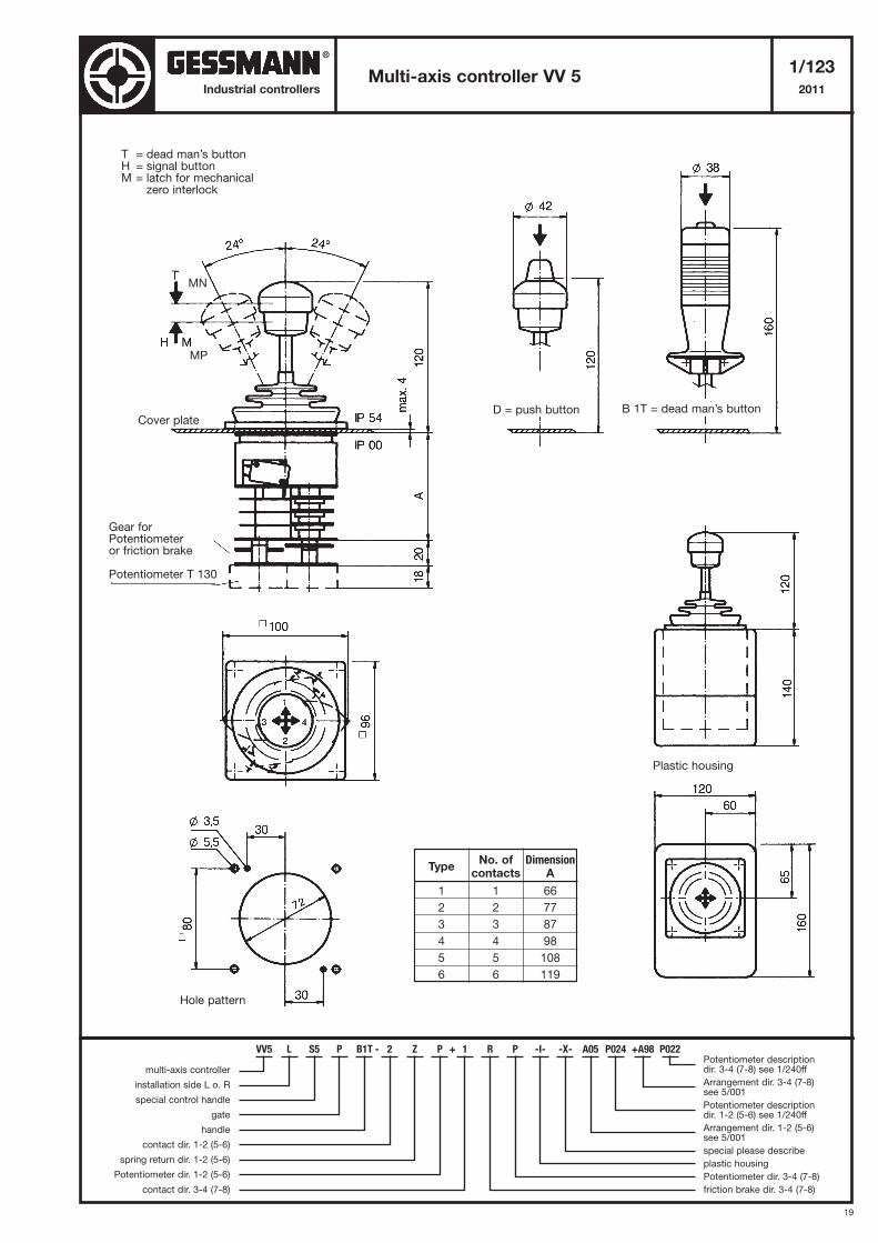
Multi-axis controller VV 51/123
2011Industrial controllers
T = dead man’s buttonH = signal buttonM = latch for mechanical
zero interlock
Cover plateD = push button
Hole pattern
Plastic housing
B 1T = dead man’s button
TypeNo. of Dimension
contacts A
1 1 66
2 2 77
3 3 87
4 4 98
5 5 108
6 6 119
Gear for Potentiometeror friction brake
Potentiometer T 130
VV5 L S5 P B1T - 2 Z P + 1 R P -I- -X- A05 P024 +A98 P022
multi-axis controller
installation side L o. R
special control handle
gate
handle
contact dir. 1-2 (5-6)
spring return dir. 1-2 (5-6)
Potentiometer dir. 1-2 (5-6)
contact dir. 3-4 (7-8)
Potentiometer descriptiondir. 3-4 (7-8) see 1/240ff
Arrangement dir. 3-4 (7-8) see 5/001
Potentiometer descriptiondir. 1-2 (5-6) see 1/240ff
Arrangement dir. 1-2 (5-6) see 5/001
special please describe
plastic housing
Potentiometer dir. 3-4 (7-8)
friction brake dir. 3-4 (7-8)
MN
MP
®
20
Industrial controllers
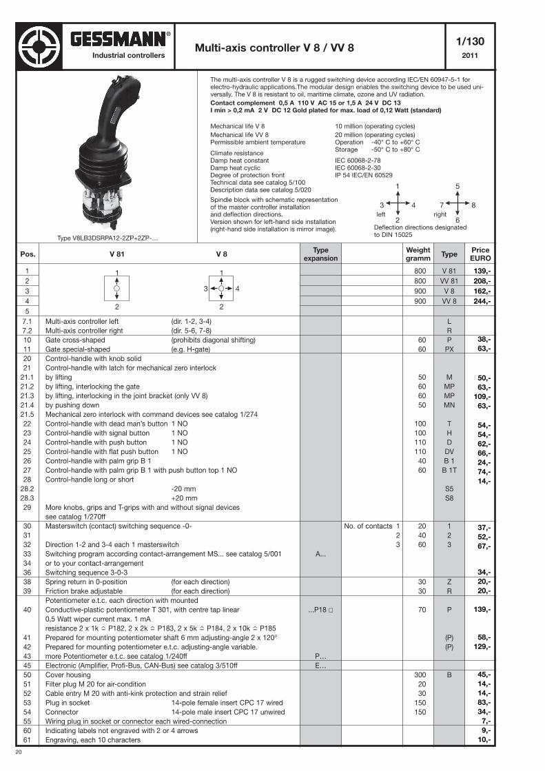
The multi-axis controller V 8 is a rugged switching device according IEC/EN 60947-5-1 forelectro-hydraulic applications.The modular design enables the switching device to be used uni-versally. The V 8 is resistant to oil, maritime climate, ozone and UV radiation.
Contact complement 0,5 A 110 V AC 15 or 1,5 A 24 V DC 13 I min > 0,2 mA 2 V DC 12 Gold plated for max. load of 0,12 Watt (standard)
Mechanical life V 8 10 million (operating cycles)
Mechanical life VV 8 20 million (operating cycles)Permissible ambient temperature Operation -40° C to +60° C
Storage -50° C to +80° CClimate resistanceDamp heat constant IEC 60068-2-78Damp heat cyclic IEC 60068-2-30Degree of protection front IP 54 IEC/EN 60529Technical data see catalog 5/100Description data see catalog 5/020
Spindle block with schematic representationof the master controller installationand deflection directions.Version shown for left-hand side installation(right-hand side installation is mirror image).
Multi-axis controller V 8 / VV 81/130
2011
1
2
3
4
5
7.1 Multi-axis controller left (dir. 1-2, 3-4)
7.2 Multi-axis controller right (dir. 5-6, 7-8)
10 Gate cross-shaped (prohibits diagonal shifting)
11 Gate special-shaped (e.g. H-gate)
20 Control-handle with knob solid
21 Control-handle with latch for mechanical zero interlock
21.1 by lifting
21.2 by lifting, interlocking the gate
21.3 by lifting, interlocking in the joint bracket (only VV 8)
21.4 by pushing down
21.5 Mechanical zero interlock with command devices see catalog 1/274
22 Control-handle with dead man’s button 1 NO
23 Control-handle with signal button 1 NO
24 Control-handle with push button 1 NO
25 Control-handle with flat push button 1 NO
26 Control-handle with palm grip B 1
27 Control-handle with palm grip B 1 with push button top 1 NO
28 Control-handle long or short
28.2 -20 mm
28.3 +20 mm
29 More knobs, grips and T-grips with and without signal devices
see catalog 1/270ff
30 Masterswitch (contact) switching sequence -0-
31
32 Direction 1-2 and 3-4 each 1 masterswitch
33 Switching program according contact-arrangement MS... see catalog 5/001
34 or to your contact-arrangement
36 Switching sequence 3-0-3
38 Spring return in 0-position (for each direction)
39 Friction brake adjustable (for each direction)
Potentiometer e.t.c. each direction with mounted
40 Conductive-plastic potentiometer T 301, with centre tap linear
0,5 Watt wiper current max. 1 mA
resistance 2 x 1k P182, 2 x 2k P183, 2 x 5k P184, 2 x 10k P185
41 Prepared for mounting potentiometer shaft 6 mm adjusting-angle 2 x 120°
42 Prepared for mounting potentiometer e.t.c. adjusting-angle variable.
43 more Potentiometer e.t.c. see catalog 1/240ff
45 Electronic (Amplifier, Profi-Bus, CAN-Bus) see catalog 3/510ff
50 Cover housing
51 Filter plug M 20 for air-condition
52 Cable entry M 20 with anti-kink protection and strain relief
53 Plug in socket 14-pole female insert CPC 17 wired
54 Connector 14-pole male insert CPC 17 unwired
55 Wiring plug in socket or connector each wired-connection
60 Indicating labels not engraved with 2 or 4 arrows
61 Engraving, each 10 characters
800
800
900
900
60
60
50
60
60
50
100
100
110
110
40
60
20
40
60
30
30
70
300
20
30
150
150
V 81
VV 81
V 8
VV 8
L
R
P
PX
M
MP
MP
MN
T
H
D
DV
B 1
B 1T
S5
S8
1
2
3
Z
R
P
(P)
(P)
B
5
7 8
6
1
3 4
2Deflection directions designatedto DIN 15025
left right
Pos. V 81 V 8Weightgramm
Typeexpansion
TypePriceEURO
A...
...P18 �
P…
E…
No. of contacts 1
2
3
1
2
1
3 4
2
Type V8LB3DSRPA12-2ZP+2ZP-…
139,-
208,-
162,-
244,-
38,-
63,-
50,-
63,-
109,-
63,-
54,-
54,-
62,-
66,-
24,-
74,-
14,-
37,-
52,-
67,-
34,-
20,-
20,-
139,-
58,-
129,-
45,-
14,-
14,-
83,-
34,-
7,-
9,-
10,-
®
21
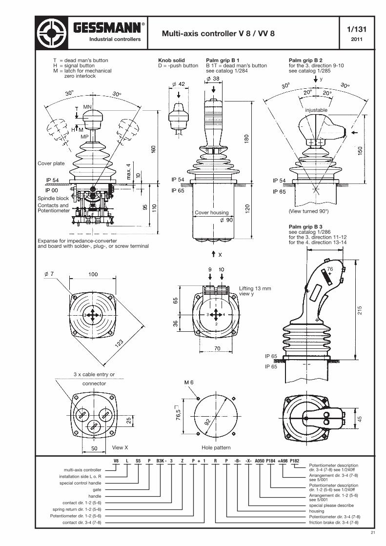
Multi-axis controller V 8 / VV 81/131
2011Industrial controllers
T = dead man’s buttonH = signal buttonM = latch for mechanical
zero interlock
Cover plate
Spindle block
Contacts andPotentiometer
Expanse for impedance-converterand board with solder-, plug-, or screw terminal
Hole pattern
Knob solidD = -push button
Palm grip B 1B 1T = dead man’s buttonsee catalog 1/284
Palm grip B 2for the 3. direction 9-10see catalog 1/285
(View turned 90°)
Palm grip B 3see catalog 1/286for the 3. direction 11-12for the 4. direction 13-14
Lifting 13 mmview y
76
45
215
IP 65
IP 65
injustable
Cover housing
3 x cable entry or
connector
View X
V8 L S5 P B3K - 3 Z P + 1 R P -B- -X- A050 P184 +A98 P182
multi-axis controller
installation side L o. R
special control handle
gate
handle
contact dir. 1-2 (5-6)
spring return dir. 1-2 (5-6)
Potentiometer dir. 1-2 (5-6)
contact dir. 3-4 (7-8)
Potentiometer descriptiondir. 3-4 (7-8) see 1/240ff
Arrangement dir. 3-4 (7-8) see 5/001
Potentiometer descriptiondir. 1-2 (5-6) see 1/240ff
Arrangement dir. 1-2 (5-6) see 5/001
special please describe
housing
Potentiometer dir. 3-4 (7-8)
friction brake dir. 3-4 (7-8)
MN
MP
y
®
22
Industrial controllers
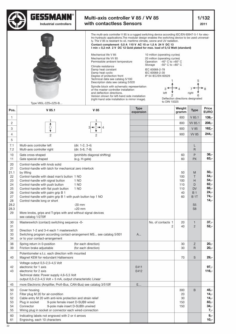
The multi-axis controller V 85 is a rugged switching device according IEC/EN 60947-5-1 for elec-tro-hydraulic applications.The modular design enables the switching device to be used universal-ly. The V 85 is resistant to oil, maritime climate, ozone and UV radiation.
Contact complement 0,5 A 110 V AC 15 or 1,5 A 24 V DC 13 I min > 0,2 mA 2 V DC 12 Gold plated for max. load of 0,12 Watt (standard)
Mechanical life V 85 10 million (operating cycles)
Mechanical life VV 85 20 million (operating cycles)Permissible ambient temperature Operation -40° C to +60° C
Storage -50° C to +80° CClimate resistanceDamp heat constant IEC 60068-2-78Damp heat cyclic IEC 60068-2-30Degree of protection front IP 54 IEC/EN 60529Technical data see catalog 5/100Description data see catalog 5/020
Spindle block with schematic representationof the master controller installationand deflection directions.Version shown for left-hand side installation(right-hand side installation is mirror image).
Multi-axis controller V 85 / VV 85 1/132
with contactless Sensors 2011
1
2
3
4
5
7.1 Multi-axis controller left (dir. 1-2, 3-4)
7.2 Multi-axis controller right (dir. 5-6, 7-8)
10 Gate cross-shaped (prohibits diagonal shifting)
11 Gate special-shaped (e.g. H-gate)
20 Control-handle with knob solid
21 Control-handle with latch for mechanical zero interlock
21.1 by lifting
22 Control-handle with dead man’s button 1 NO
23 Control-handle with signal button 1 NO
24 Control-handle with push button 1 NO
25 Control-handle with flat push button 1 NO
26 Control-handle with palm grip B 1
27 Control-handle with palm grip B 1 with push button top 1 NO
28 Control-handle long or short
28.2 -20 mm
28.3 +20 mm
29 More knobs, grips and T-grips with and without signal devices
see catalog 1/270ff
30 Masterswitch (contact) switching sequence -0-
31
32 Direction 1-2 and 3-4 each 1 masterswitch
33 Switching program according contact-arrangement MS... see catalog 5/001
34 or to your contact-arrangement
38 Spring return in 0-position (for each direction)
39 Friction brake adjustable (for each direction)
Potentiometer e.t.c. each direction with mounted
40 Magnet KEM for redundant Hallsensors
Voltage output 0,5–2,5–4,5 Volt
42 electronic for 1 axis
43 electronic for 2 axis
Technical data: Power supply 4,6–5,5 Volt
output 0,5–2,5–4,5 Volt + 5 mA, output characteristic Linear
45 more Electronic (Amplifier, Profi-Bus, CAN-Bus) see catalog 3/510ff
50 Cover housing
51 Filter plug M 20 for air-condition
52 Cable entry M 20 with anti-kink protection and strain relief
53 Plug in socket 9-pole female insert D-SUB9 wired
54 Connector 9-pole male insert D-SUB9 unwired
55 Wiring plug in socket or connector each wired-connection
60 Indicating labels not engraved with 2 or 4 arrows
61 Engraving, each 10 characters
800
800
900
900
60
60
50
100
100
110
110
40
60
20
40
30
30
70
300
20
30
150
150
V 85.1
VV 85.1
V 85
VV 85
L
R
P
PX
M
T
H
D
DV
B 1
B 1T
S5
S8
1
2
Z
R
S
B
5
7 8
6
1
3 4
2Deflection directions designatedto DIN 15025
left right
Pos. V 85.1 V 85Weightgramm
Typeexpansion
TypePriceEURO
No. of contacts 1
2
1
2
1
3 4
2
A...
E411
E412
E…
Type V85L-2ZS+2ZS-B…
139,-
208,-
162,-
244,-
38,-
63,-
50,-
54,-
54,-
62,-
66,-
24,-
74,-
14,-
37,-
52,-
20,-
20,-
29,-
97,-
116,-
45,-
14,-
14,-
83,-
34,-
7,-
9,-
10,-
®
23
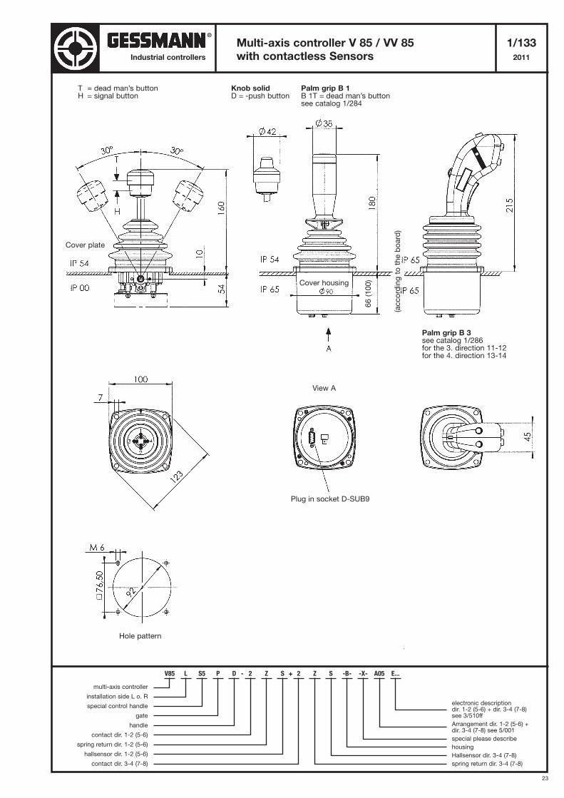
Multi-axis controller V 85 / VV 85 1/133
with contactless Sensors 2011Industrial controllers
T = dead man’s buttonH = signal button
Cover plate
Hole pattern
Knob solidD = -push button
Palm grip B 1B 1T = dead man’s buttonsee catalog 1/284
Palm grip B 3see catalog 1/286for the 3. direction 11-12for the 4. direction 13-14
Cover housing
Plug in socket D-SUB9
View A
V85 L S5 P D - 2 Z S + 2 Z S -B- -X- A05 E...
multi-axis controller
installation side L o. R
special control handle
gate
handle
contact dir. 1-2 (5-6)
spring return dir. 1-2 (5-6)
hallsensor dir. 1-2 (5-6)
contact dir. 3-4 (7-8)
electronic descriptiondir. 1-2 (5-6) + dir. 3-4 (7-8)see 3/510ff
Arrangement dir. 1-2 (5-6) +dir. 3-4 (7-8) see 5/001
special please describe
housing
Hallsensor dir. 3-4 (7-8)
spring return dir. 3-4 (7-8)
®
66 (100)
(according to the board)
24
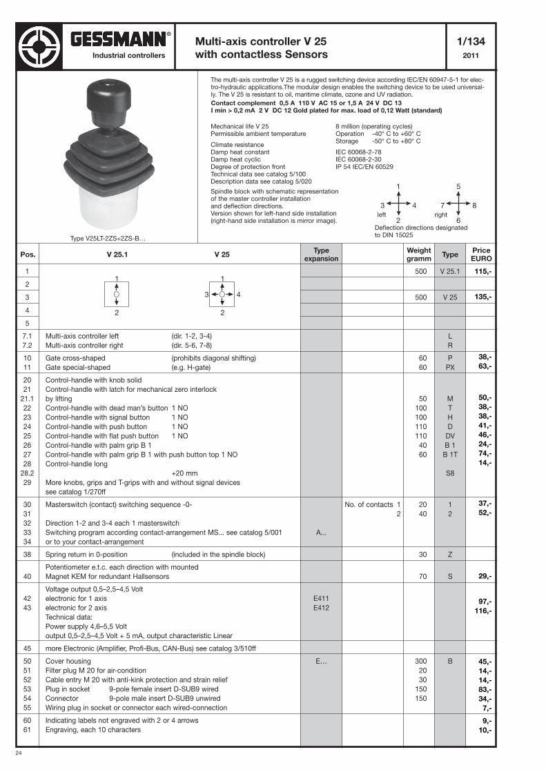
Industrial controllers
The multi-axis controller V 25 is a rugged switching device according IEC/EN 60947-5-1 for elec-tro-hydraulic applications.The modular design enables the switching device to be used universal-ly. The V 25 is resistant to oil, maritime climate, ozone and UV radiation.
Contact complement 0,5 A 110 V AC 15 or 1,5 A 24 V DC 13 I min > 0,2 mA 2 V DC 12 Gold plated for max. load of 0,12 Watt (standard)
Mechanical life V 25 8 million (operating cycles)Permissible ambient temperature Operation -40° C to +60° C
Storage -50° C to +80° CClimate resistanceDamp heat constant IEC 60068-2-78Damp heat cyclic IEC 60068-2-30Degree of protection front IP 54 IEC/EN 60529Technical data see catalog 5/100Description data see catalog 5/020
Spindle block with schematic representationof the master controller installationand deflection directions.Version shown for left-hand side installation(right-hand side installation is mirror image).
Multi-axis controller V 25 1/134
with contactless Sensors 2011
1
2
3
4
5
7.1 Multi-axis controller left (dir. 1-2, 3-4)
7.2 Multi-axis controller right (dir. 5-6, 7-8)
10 Gate cross-shaped (prohibits diagonal shifting)
11 Gate special-shaped (e.g. H-gate)
20 Control-handle with knob solid
21 Control-handle with latch for mechanical zero interlock
21.1 by lifting
22 Control-handle with dead man’s button 1 NO
23 Control-handle with signal button 1 NO
24 Control-handle with push button 1 NO
25 Control-handle with flat push button 1 NO
26 Control-handle with palm grip B 1
27 Control-handle with palm grip B 1 with push button top 1 NO
28 Control-handle long
28.2 +20 mm
29 More knobs, grips and T-grips with and without signal devices
see catalog 1/270ff
30 Masterswitch (contact) switching sequence -0-
31
32 Direction 1-2 and 3-4 each 1 masterswitch
33 Switching program according contact-arrangement MS... see catalog 5/001
34 or to your contact-arrangement
38 Spring return in 0-position (included in the spindle block)
Potentiometer e.t.c. each direction with mounted
40 Magnet KEM for redundant Hallsensors
Voltage output 0,5–2,5–4,5 Volt
42 electronic for 1 axis
43 electronic for 2 axis
Technical data:
Power supply 4,6–5,5 Volt
output 0,5–2,5–4,5 Volt + 5 mA, output characteristic Linear
45 more Electronic (Amplifier, Profi-Bus, CAN-Bus) see catalog 3/510ff
50 Cover housing
51 Filter plug M 20 for air-condition
52 Cable entry M 20 with anti-kink protection and strain relief
53 Plug in socket 9-pole female insert D-SUB9 wired
54 Connector 9-pole male insert D-SUB9 unwired
55 Wiring plug in socket or connector each wired-connection
60 Indicating labels not engraved with 2 or 4 arrows
61 Engraving, each 10 characters
500
500
60
60
50
100
100
110
110
40
60
20
40
30
70
300
20
30
150
150
V 25.1
V 25
L
R
P
PX
M
T
H
D
DV
B 1
B 1T
S8
1
2
Z
S
B
5
7 8
6
1
3 4
2Deflection directions designatedto DIN 15025
left right
1
2
1
3 4
2
Pos. V 25.1 V 25Weightgramm
Typeexpansion
TypePriceEURO
No. of contacts 1
2
A...
E411
E412
E…
Type V25LT-2ZS+2ZS-B…
115,-
135,-
38,-
63,-
50,-
38,-
38,-
41,-
46,-
24,-
74,-
14,-
37,-
52,-
29,-
97,-
116,-
45,-
14,-
14,-
83,-
34,-
7,-
9,-
10,-
®
25
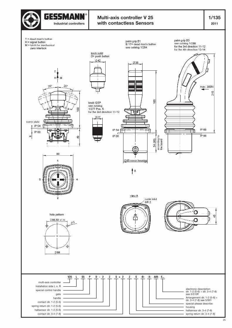
Multi-axis controller V 25 1/135
with contactless Sensors 2011Industrial controllers
V25 L S5 P D - 2 Z S + 2 Z S -B- -X- A05 E...
multi-axis controller
installation side L o. R
special control handle
gate
handle
contact dir. 1-2 (5-6)
spring return dir. 1-2 (5-6)
hallsensor dir. 1-2 (5-6)
contact dir. 3-4 (7-8)
electronic descriptiondir. 1-2 (5-6) + dir. 3-4 (7-8)see 3/510ff
Arrangement dir. 1-2 (5-6) +dir. 3-4 (7-8) see 5/001
special please describe
housing
hallsensor dir. 3-4 (7-8)
spring return dir. 3-4 (7-8)
®
26
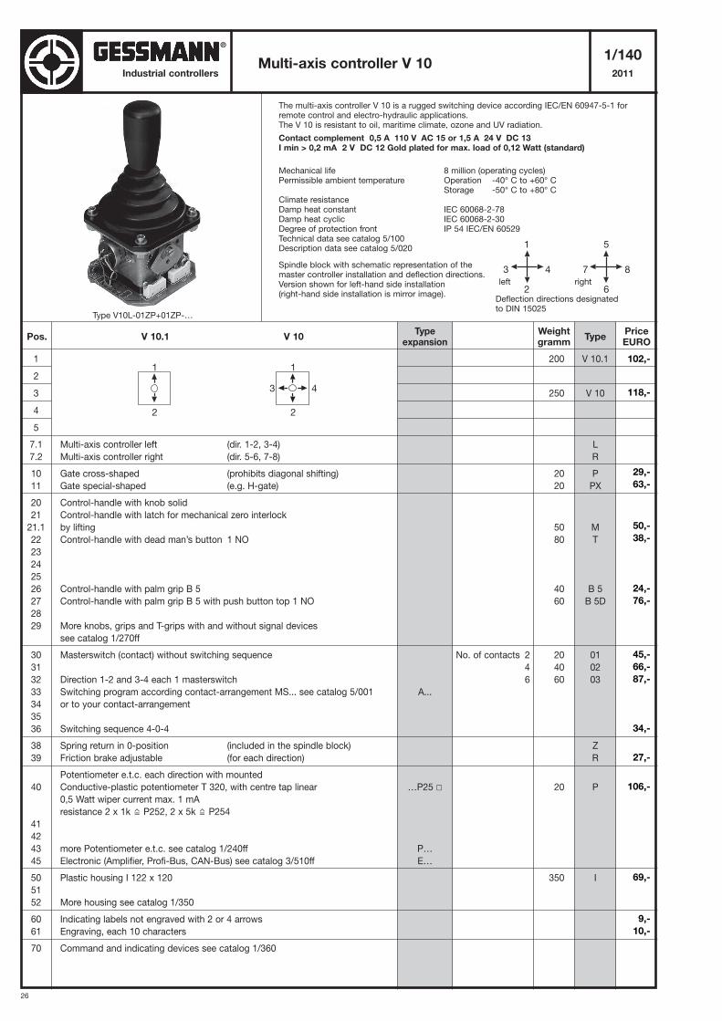
Industrial controllers
The multi-axis controller V 10 is a rugged switching device according IEC/EN 60947-5-1 forremote control and electro-hydraulic applications.The V 10 is resistant to oil, maritime climate, ozone and UV radiation.
Contact complement 0,5 A 110 V AC 15 or 1,5 A 24 V DC 13 I min > 0,2 mA 2 V DC 12 Gold plated for max. load of 0,12 Watt (standard)
Mechanical life 8 million (operating cycles)Permissible ambient temperature Operation -40° C to +60° C
Storage -50° C to +80° CClimate resistanceDamp heat constant IEC 60068-2-78Damp heat cyclic IEC 60068-2-30Degree of protection front IP 54 IEC/EN 60529Technical data see catalog 5/100Description data see catalog 5/020
Spindle block with schematic representation of the master controller installation and deflection directions. Version shown for left-hand side installation(right-hand side installation is mirror image).
Multi-axis controller V 101/140
2011
1
2
3
4
5
7.1 Multi-axis controller left (dir. 1-2, 3-4)
7.2 Multi-axis controller right (dir. 5-6, 7-8)
10 Gate cross-shaped (prohibits diagonal shifting)
11 Gate special-shaped (e.g. H-gate)
20 Control-handle with knob solid
21 Control-handle with latch for mechanical zero interlock
21.1 by lifting
22 Control-handle with dead man’s button 1 NO
23
24
25
26 Control-handle with palm grip B 5
27 Control-handle with palm grip B 5 with push button top 1 NO
28
29 More knobs, grips and T-grips with and without signal devices
see catalog 1/270ff
30 Masterswitch (contact) without switching sequence
31
32 Direction 1-2 and 3-4 each 1 masterswitch
33 Switching program according contact-arrangement MS... see catalog 5/001
34 or to your contact-arrangement
35
36 Switching sequence 4-0-4
38 Spring return in 0-position (included in the spindle block)
39 Friction brake adjustable (for each direction)
Potentiometer e.t.c. each direction with mounted
40 Conductive-plastic potentiometer T 320, with centre tap linear
0,5 Watt wiper current max. 1 mA
resistance 2 x 1k P252, 2 x 5k P254
41
42
43 more Potentiometer e.t.c. see catalog 1/240ff
45 Electronic (Amplifier, Profi-Bus, CAN-Bus) see catalog 3/510ff
50 Plastic housing I 122 x 120
51
52 More housing see catalog 1/350
60 Indicating labels not engraved with 2 or 4 arrows
61 Engraving, each 10 characters
70 Command and indicating devices see catalog 1/360
200
250
20
20
50
80
40
60
20
40
60
20
350
V 10.1
V 10
L
R
P
PX
M
T
B 5
B 5D
01
02
03
Z
R
P
I
5
7 8
6
1
3 4
2Deflection directions designatedto DIN 15025
left right
Pos. V 10.1 V 10Weightgramm
Typeexpansion
TypePriceEURO
No. of contacts 2
4
6
A...
…P25 �
P…
E…
1
2
1
3 4
2
Type V10L-01ZP+01ZP-…
102,-
118,-
29,-
63,-
50,-
38,-
24,-
76,-
45,-
66,-
87,-
34,-
27,-
106,-
69,-
9,-
10,-
®
27
Multi-axis controller V 101/141
2011Industrial controllers
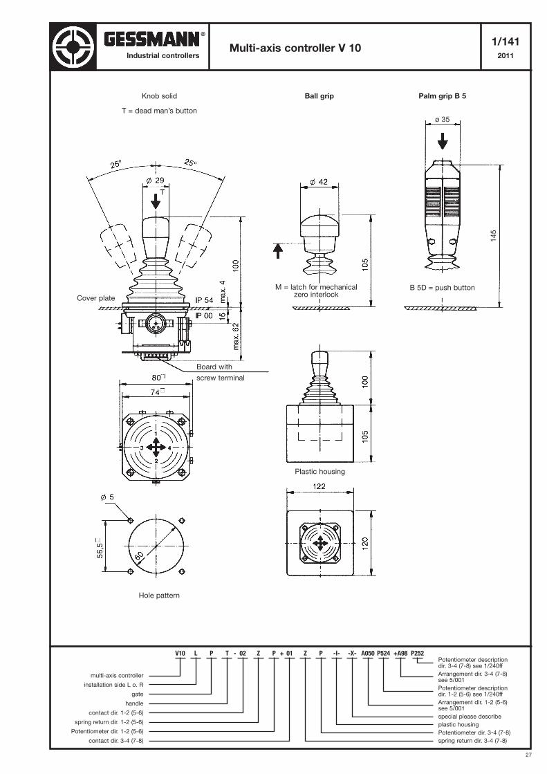
Knob solid
T = dead man’s button
M = latch for mechanicalzero interlock
Hole pattern
Cover plate
Board with
screw terminal
Plastic housing
Ball grip Palm grip B 5
B 5D = push button
ø 35
145
V10 L P T - 02 Z P + 01 Z P -I- -X- A050 P524 +A98 P252
multi-axis controller
installation side L o. R
gate
handle
contact dir. 1-2 (5-6)
spring return dir. 1-2 (5-6)
Potentiometer dir. 1-2 (5-6)
contact dir. 3-4 (7-8)
Potentiometer descriptiondir. 3-4 (7-8) see 1/240ff
Arrangement dir. 3-4 (7-8) see 5/001
Potentiometer descriptiondir. 1-2 (5-6) see 1/240ff
Arrangement dir. 1-2 (5-6) see 5/001
special please describe
plastic housing
Potentiometer dir. 3-4 (7-8)
spring return dir. 3-4 (7-8)
®
28
Industrial controllersMulti-axis controller V 14
1/142
2011
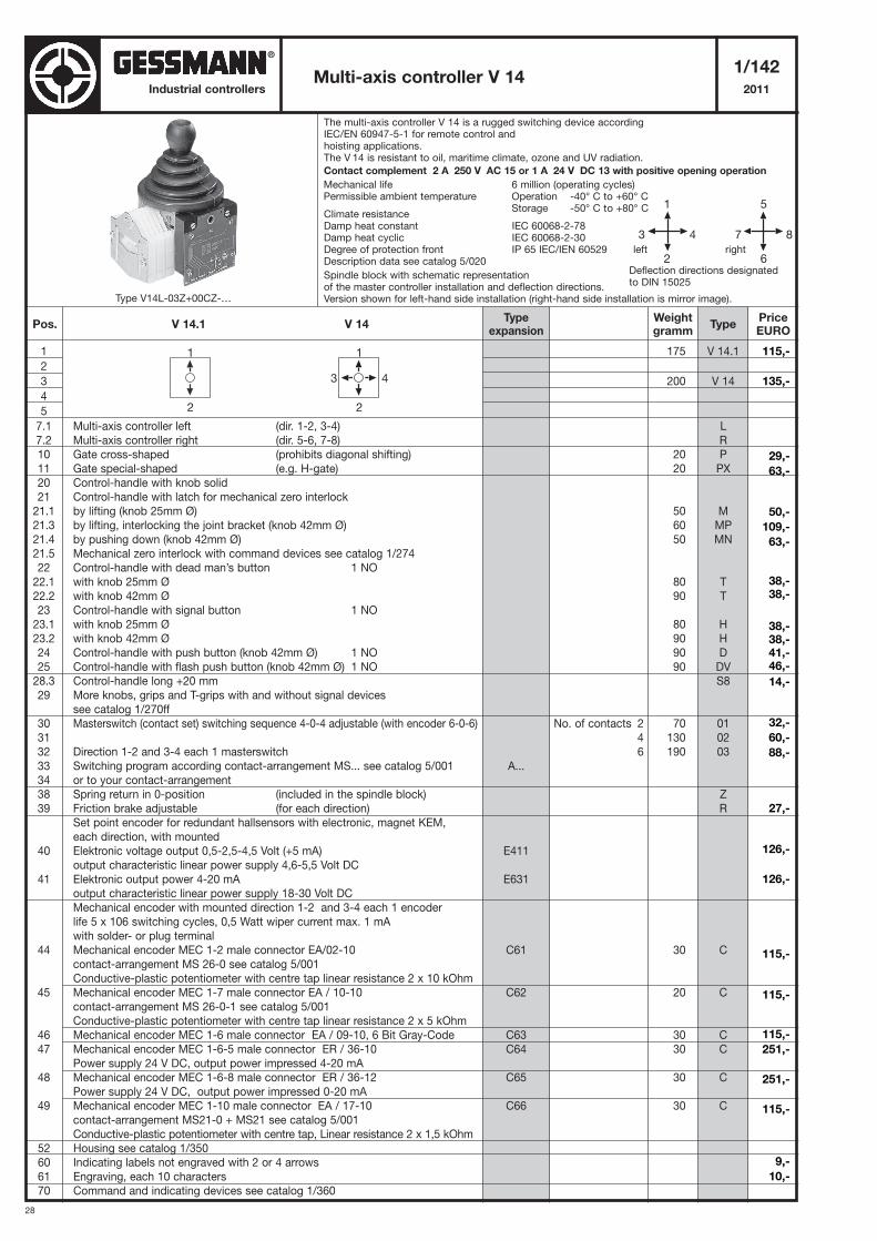
The multi-axis controller V 14 is a rugged switching device accordingIEC/EN 60947-5-1 for remote control andhoisting applications.The V 14 is resistant to oil, maritime climate, ozone and UV radiation.
Contact complement 2 A 250 V AC 15 or 1 A 24 V DC 13 with positive opening operation
Mechanical life 6 million (operating cycles)Permissible ambient temperature Operation -40° C to +60° C
Storage -50° C to +80° CClimate resistanceDamp heat constant IEC 60068-2-78Damp heat cyclic IEC 60068-2-30Degree of protection front IP 65 IEC/IEN 60529Description data see catalog 5/020
Spindle block with schematic representationof the master controller installation and deflection directions.Version shown for left-hand side installation (right-hand side installation is mirror image).
1
2
3
4
5
7.1 Multi-axis controller left (dir. 1-2, 3-4)
7.2 Multi-axis controller right (dir. 5-6, 7-8)
10 Gate cross-shaped (prohibits diagonal shifting)
11 Gate special-shaped (e.g. H-gate)
20 Control-handle with knob solid
21 Control-handle with latch for mechanical zero interlock
21.1 by lifting (knob 25mm Ø)
21.3 by lifting, interlocking the joint bracket (knob 42mm Ø)
21.4 by pushing down (knob 42mm Ø)
21.5 Mechanical zero interlock with command devices see catalog 1/274
22 Control-handle with dead man’s button 1 NO
22.1 with knob 25mm Ø
22.2 with knob 42mm Ø
23 Control-handle with signal button 1 NO
23.1 with knob 25mm Ø
23.2 with knob 42mm Ø
24 Control-handle with push button (knob 42mm Ø) 1 NO
25 Control-handle with flash push button (knob 42mm Ø) 1 NO
28.3 Control-handle long +20 mm
29 More knobs, grips and T-grips with and without signal devices
see catalog 1/270ff
30 Masterswitch (contact set) switching sequence 4-0-4 adjustable (with encoder 6-0-6)
31
32 Direction 1-2 and 3-4 each 1 masterswitch
33 Switching program according contact-arrangement MS... see catalog 5/001
34 or to your contact-arrangement
38 Spring return in 0-position (included in the spindle block)
39 Friction brake adjustable (for each direction)
Set point encoder for redundant hallsensors with electronic, magnet KEM,
each direction, with mounted
40 Elektronic voltage output 0,5-2,5-4,5 Volt (+5 mA)
output characteristic linear power supply 4,6-5,5 Volt DC
41 Elektronic output power 4-20 mA
output characteristic linear power supply 18-30 Volt DC
Mechanical encoder with mounted direction 1-2 and 3-4 each 1 encoder
life 5 x 10⁶ switching cycles, 0,5 Watt wiper current max. 1 mA
with solder- or plug terminal
44 Mechanical encoder MEC 1-2 male connector EA/02-10
contact-arrangement MS 26-0 see catalog 5/001
Conductive-plastic potentiometer with centre tap linear resistance 2 x 10 kOhm
45 Mechanical encoder MEC 1-7 male connector EA / 10-10
contact-arrangement MS 26-0-1 see catalog 5/001
Conductive-plastic potentiometer with centre tap linear resistance 2 x 5 kOhm
46 Mechanical encoder MEC 1-6 male connector EA / 09-10, 6 Bit Gray-Code
47 Mechanical encoder MEC 1-6-5 male connector ER / 36-10
Power supply 24 V DC, output power impressed 4-20 mA
48 Mechanical encoder MEC 1-6-8 male connector ER / 36-12
Power supply 24 V DC, output power impressed 0-20 mA
49 Mechanical encoder MEC 1-10 male connector EA / 17-10
contact-arrangement MS21-0 + MS21 see catalog 5/001
Conductive-plastic potentiometer with centre tap, Linear resistance 2 x 1,5 kOhm
52 Housing see catalog 1/350
60 Indicating labels not engraved with 2 or 4 arrows
61 Engraving, each 10 characters
70 Command and indicating devices see catalog 1/360
175
200
20
20
50
60
50
80
90
80
90
90
90
70
130
190
30
20
30
30
30
30
V 14.1
V 14
L
R
P
PX
M
MP
MN
T
T
H
H
D
DV
S8
01
02
03
Z
R
C
C
C
C
C
C
1
2
1
3 4
2
Pos. V 14.1 V 14Weightgramm
Typeexpansion
TypePriceEURO
No. of contacts 2
4
6
A...
E411
E631
C61
C62
C63
C64
C65
C66
Type V14L-03Z+00CZ-…
115,-
135,-
29,-
63,-
50,-
109,-
63,-
38,-38,-
38,-38,-41,-46,-
14,-
32,-
60,-
88,-
27,-
126,-
126,-
115,-
115,-
115,-
251,-
251,-
115,-
9,-
10,-
5
7 8
6
1
3 4
2Deflection directions designatedto DIN 15025
left right
®
29
Multi-axis controller V 141/143
2011Industrial controllers
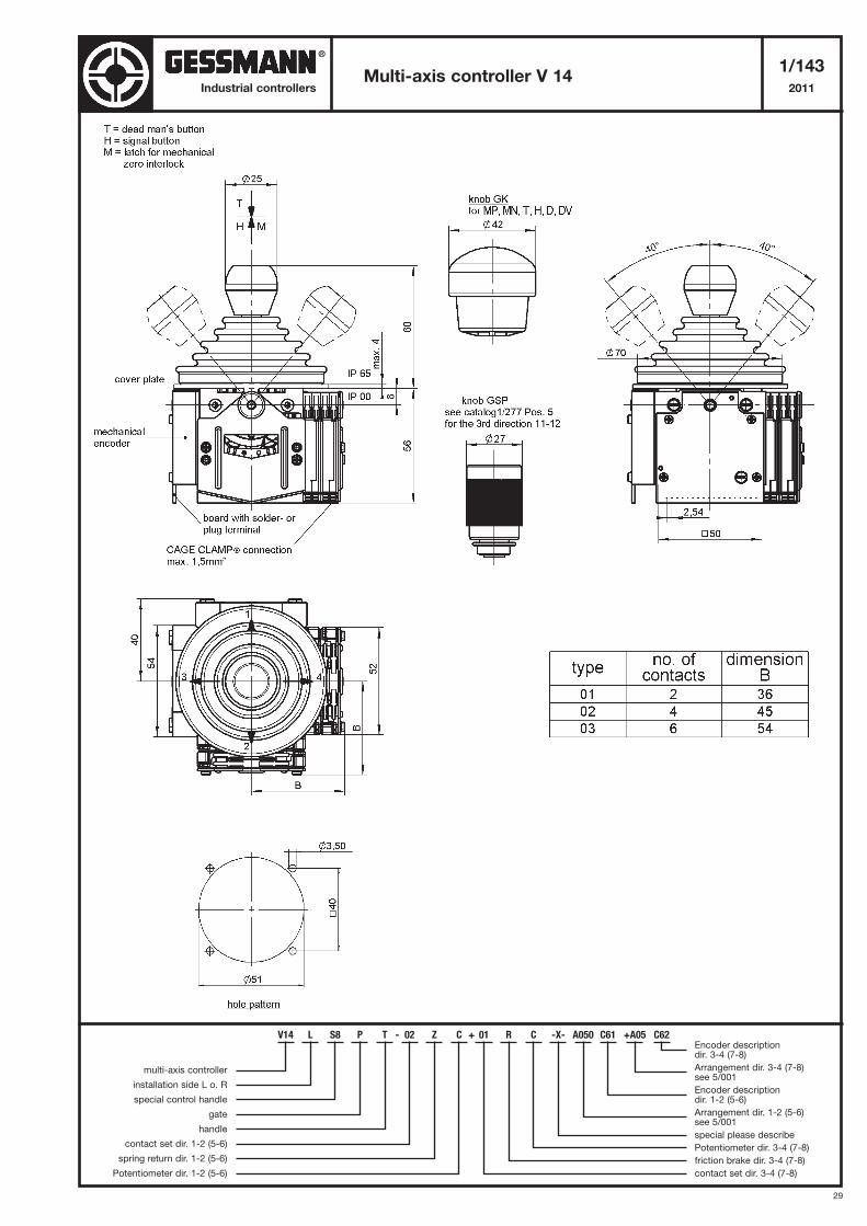
V14 L S8 P T - 02 Z C + 01 R C -X- A050 C61 +A05 C62
multi-axis controller
installation side L o. R
special control handle
gate
handle
contact set dir. 1-2 (5-6)
spring return dir. 1-2 (5-6)
Potentiometer dir. 1-2 (5-6)
Encoder descriptiondir. 3-4 (7-8)
Arrangement dir. 3-4 (7-8) see 5/001
Encoder descriptiondir. 1-2 (5-6)
Arrangement dir. 1-2 (5-6) see 5/001
special please describe
Potentiometer dir. 3-4 (7-8)
friction brake dir. 3-4 (7-8)
contact set dir. 3-4 (7-8)
®
30
Industrial controllers
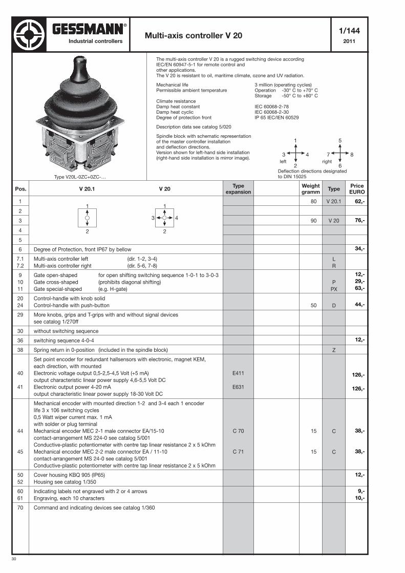
The multi-axis controller V 20 is a rugged switching device accordingIEC/EN 60947-5-1 for remote control andother applications.The V 20 is resistant to oil, maritime climate, ozone and UV radiation.
Mechanical life 3 million (operating cycles)Permissible ambient temperature Operation -30° C to +70° C
Storage -50° C to +80° CClimate resistanceDamp heat constant IEC 60068-2-78Damp heat cyclic IEC 60068-2-30Degree of protection front IP 65 IEC/IEN 60529
Description data see catalog 5/020
Spindle block with schematic representationof the master controller installationand deflection directions.Version shown for left-hand side installation(right-hand side installation is mirror image).
Multi-axis controller V 201/144
2011
1
2
3
4
5
6 Degree of Protection, front IP67 by bellow
7.1 Multi-axis controller left (dir. 1-2, 3-4)
7.2 Multi-axis controller right (dir. 5-6, 7-8)
9 Gate open-shaped for open shifting switching sequence 1-0-1 to 3-0-3
10 Gate cross-shaped (prohibits diagonal shifting)
11 Gate special-shaped (e.g. H-gate)
20 Control-handle with knob solid
24 Control-handle with push-button
29 More knobs, grips and T-grips with and without signal devices
see catalog 1/270ff
30 without switching sequence
36 switching sequence 4-0-4
38 Spring return in 0-position (included in the spindle block)
Set point encoder for redundant hallsensors with electronic, magnet KEM,
each direction, with mounted
40 Electronic voltage output 0,5-2,5-4,5 Volt (+5 mA)
output characteristic linear power supply 4,6-5,5 Volt DC
41 Electronic output power 4-20 mA
output characteristic linear power supply 18-30 Volt DC
Mechanical encoder with mounted direction 1-2 and 3-4 each 1 encoder
life 3 x 10⁶ switching cycles
0,5 Watt wiper current max. 1 mA
with solder or plug terminal
44 Mechanical encoder MEC 2-1 male connector EA/15-10
contact-arrangement MS 224-0 see catalog 5/001
Conductive-plastic potentiometer with centre tap linear resistance 2 x 5 kOhm
45 Mechanical encoder MEC 2-2 male connector EA / 11-10
contact-arrangement MS 24-0 see catalog 5/001
Conductive-plastic potentiometer with centre tap linear resistance 2 x 5 kOhm
50 Cover housing KBQ 905 (IP65)
52 Housing see catalog 1/350
60 Indicating labels not engraved with 2 or 4 arrows
61 Engraving, each 10 characters
70 Command and indicating devices see catalog 1/360
80
90
50
15
15
V 20.1
V 20
L
R
P
PX
D
Z
C
C
5
7 8
6
1
3 4
2Deflection directions designatedto DIN 15025
left right
1
2
1
3 4
2
Pos. V 20.1 V 20Weightgramm
Typeexpansion
TypePriceEURO
E411
E631
C 70
C 71
Type V20L-0ZC+0ZC-…
62,-
76,-
34,-
12,-
29,-
63,-
44,-
12,-
126,-
126,-
38,-
38,-
12,-
9,-
10,-
®
31
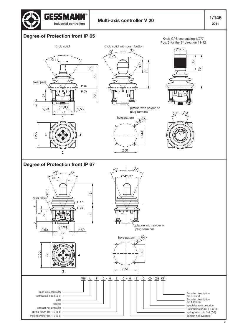
Multi-axis controller V 201/145
2011Industrial controllers
V20 L P D - 0 Z C + 0 Z C -X- C70 C71
multi-axis controller
installation side L o. R
gate
handle
contact not available
spring return dir. 1-2 (5-6)
Potentiometer dir. 1-2 (5-6)
Encoder descriptiondir. 3-4 (7-8
Encoder descriptiondir. 1-2 (5-6)
special please describe
Potentiometer dir. 3-4 (7-8)
spring return dir. 3-4 (7-8)
contact not available
Degree of Protection front IP 65
Degree of Protection front IP 67
Knob GPS see catalog 1/277
Pos. 5 for the 3rd direction 11-12
Knob solid
cover plate
platine with solder or
plug terminal
hole pattern
cover plate
platine with solder or
plug terminal
hole pattern
Knob solid with push button
®
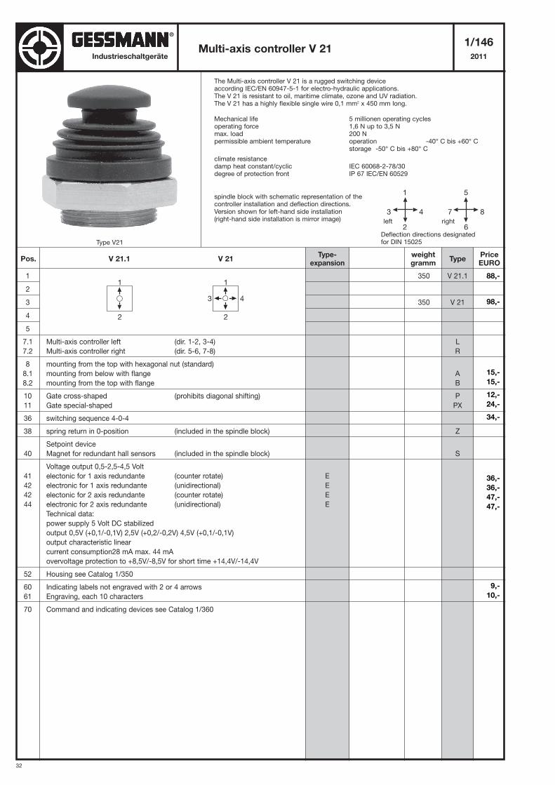
32
Industrieschaltgeräte
The Multi-axis controller V 21 is a rugged switching device according IEC/EN 60947-5-1 for electro-hydraulic applications.The V 21 is resistant to oil, maritime climate, ozone and UV radiation.The V 21 has a highly flexible single wire 0,1 mm2 x 450 mm long.
Mechanical life 5 millionen operating cyclesoperating force 1,6 N up to 3,5 Nmax. load 200 Npermissible ambient temperature operation -40° C bis +60° C
storage -50° C bis +80° C
climate resistancedamp heat constant/cyclic IEC 60068-2-78/30degree of protection front IP 67 IEC/EN 60529
spindle block with schematic representation of the controller installation and deflection directions.Version shown for left-hand side installation(right-hand side installation is mirror image)
Multi-axis controller V 211/146
2011
1
2
3
4
5
7.1 Multi-axis controller left (dir. 1-2, 3-4)
7.2 Multi-axis controller right (dir. 5-6, 7-8)
8 mounting from the top with hexagonal nut (standard)
8.1 mounting from below with flange
8.2 mounting from the top with flange
10 Gate cross-shaped (prohibits diagonal shifting)
11 Gate special-shaped
36 switching sequence 4-0-4
38 spring return in 0-position (included in the spindle block)
Setpoint device
40 Magnet for redundant hall sensors (included in the spindle block)
Voltage output 0,5-2,5-4,5 Volt
41 electonic for 1 axis redundante (counter rotate)
42 electronic for 1 axis redundante (unidirectional)
42 electonic for 2 axis redundante (counter rotate)
44 electronic for 2 axis redundante (unidirectional)
Technical data:
power supply 5 Volt DC stabilized
output 0,5V (+0,1/-0,1V) 2,5V (+0,2/-0,2V) 4,5V (+0,1/-0,1V)
output characteristic linear
current consumption28 mA max. 44 mA
overvoltage protection to +8,5V/-8,5V for short time +14,4V/-14,4V
52 Housing see Catalog 1/350
60 Indicating labels not engraved with 2 or 4 arrows
61 Engraving, each 10 characters
70 Command and indicating devices see Catalog 1/360
350
350
V 21.1
V 21
L
R
A
B
P
PX
Z
S
88,-
98,-
15,-
15,-
12,-
24,-
34,-
36,-
36,-
47,-
47,-
9,-
10,-
5
7 8
6
1
3 4
2Deflection directions designatedfor DIN 15025
left right
1
2
1
3 4
2
Pos. V 21.1 V 21weightgramm
Type-expansion
TypePriceEURO
E
E
E
E
Type V21
®
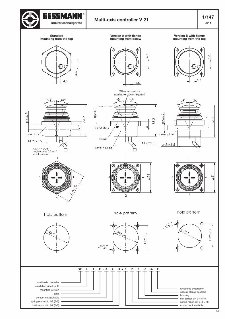
33
Multi-axis controller V 211/147
2011Industrieschaltgeräte
V21 L A P - 0 Z S + 0 Z S -B -X- E
multi-axis controller
installation side L o. R
mounting version
gate
contact not available
spring return dir. 1-2 (5-6)
Hall sensor dir. 1-2 (5-6)
Electronic description
special please describe
housing
hall sensor dir. 3-4 (7-8)
spring return dir. 3-4 (7-8)
contact not available
Version B with flangemounting from the top
Version A with flangemounting from below
Standardmounting from the top
Other actuatorsavailable upon request
®
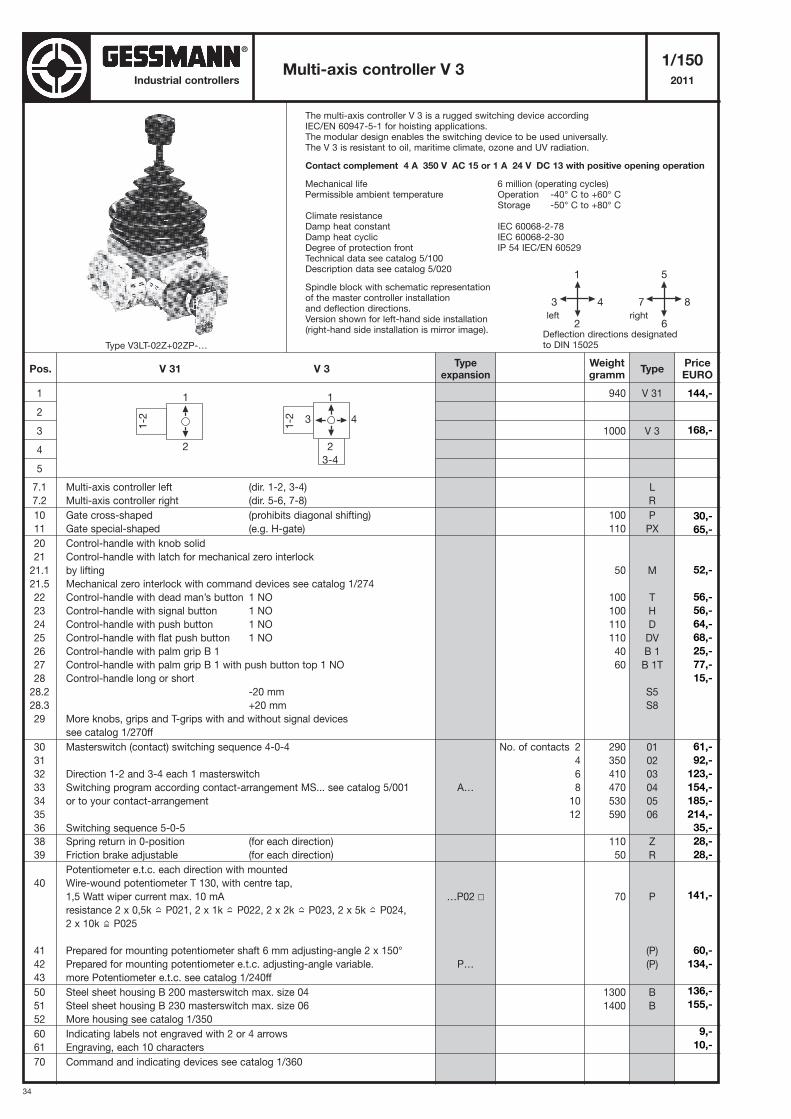
34
Industrial controllers
The multi-axis controller V 3 is a rugged switching device accordingIEC/EN 60947-5-1 for hoisting applications.The modular design enables the switching device to be used universally.The V 3 is resistant to oil, maritime climate, ozone and UV radiation.
Contact complement 4 A 350 V AC 15 or 1 A 24 V DC 13 with positive opening operation
Mechanical life 6 million (operating cycles)Permissible ambient temperature Operation -40° C to +60° C
Storage -50° C to +80° CClimate resistanceDamp heat constant IEC 60068-2-78Damp heat cyclic IEC 60068-2-30Degree of protection front IP 54 IEC/EN 60529Technical data see catalog 5/100Description data see catalog 5/020
Spindle block with schematic representationof the master controller installationand deflection directions.Version shown for left-hand side installation(right-hand side installation is mirror image).
Multi-axis controller V 31/150
2011
1
2
3
4
5
7.1 Multi-axis controller left (dir. 1-2, 3-4)
7.2 Multi-axis controller right (dir. 5-6, 7-8)
10 Gate cross-shaped (prohibits diagonal shifting)
11 Gate special-shaped (e.g. H-gate)
20 Control-handle with knob solid
21 Control-handle with latch for mechanical zero interlock
21.1 by lifting
21.5 Mechanical zero interlock with command devices see catalog 1/274
22 Control-handle with dead man’s button 1 NO
23 Control-handle with signal button 1 NO
24 Control-handle with push button 1 NO
25 Control-handle with flat push button 1 NO
26 Control-handle with palm grip B 1
27 Control-handle with palm grip B 1 with push button top 1 NO
28 Control-handle long or short
28.2 -20 mm
28.3 +20 mm
29 More knobs, grips and T-grips with and without signal devices
see catalog 1/270ff
30 Masterswitch (contact) switching sequence 4-0-4
31
32 Direction 1-2 and 3-4 each 1 masterswitch
33 Switching program according contact-arrangement MS... see catalog 5/001
34 or to your contact-arrangement
35
36 Switching sequence 5-0-5
38 Spring return in 0-position (for each direction)
39 Friction brake adjustable (for each direction)
Potentiometer e.t.c. each direction with mounted
40 Wire-wound potentiometer T 130, with centre tap,
1,5 Watt wiper current max. 10 mA
resistance 2 x 0,5k P021, 2 x 1k P022, 2 x 2k P023, 2 x 5k P024,
2 x 10k P025
41 Prepared for mounting potentiometer shaft 6 mm adjusting-angle 2 x 150°
42 Prepared for mounting potentiometer e.t.c. adjusting-angle variable.
43 more Potentiometer e.t.c. see catalog 1/240ff
50 Steel sheet housing B 200 masterswitch max. size 04
51 Steel sheet housing B 230 masterswitch max. size 06
52 More housing see catalog 1/350
60 Indicating labels not engraved with 2 or 4 arrows
61 Engraving, each 10 characters
70 Command and indicating devices see catalog 1/360
940
1000
100
110
50
100
100
110
110
40
60
290
350
410
470
530
590
110
50
70
1300
1400
V 31
V 3
L
R
P
PX
M
T
H
D
DV
B 1
B 1T
S5
S8
01
02
03
04
05
06
Z
R
P
(P)
(P)
B
B
5
7 8
6
1
3 4
2Deflection directions designatedto DIN 15025
left right
Pos. V 31 V 3Weightgramm
Typeexpansion
TypePriceEURO
No. of contacts 2
4
6
8
10
12
A…
…P02 �
P…
1
1-2
2
1
1-2
2
3-4
3 4
Type V3LT-02Z+02ZP-…
144,-
168,-
30,-
65,-
52,-
56,-
56,-
64,-
68,-
25,-
77,-
15,-
61,-
92,-
123,-
154,-
185,-
214,-
35,-
28,-
28,-
141,-
60,-
134,-
136,-
155,-
9,-
10,-
®
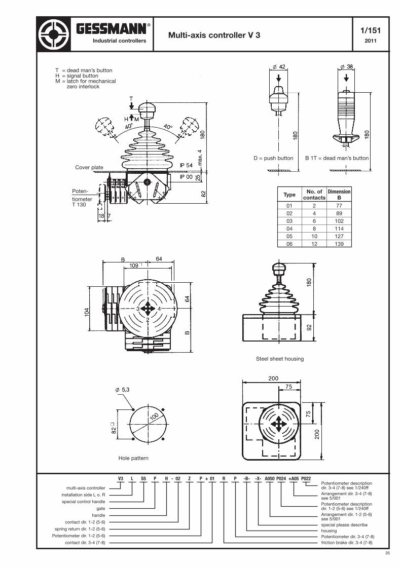
35
Multi-axis controller V 31/151
2011Industrial controllers
T = dead man’s buttonH = signal buttonM = latch for mechanical
zero interlock
Cover plate
Poten-
tiometerT 130
D = push button
Steel sheet housing
Hole pattern
B 1T = dead man’s button
TypeNo. of Dimension
contacts B
01 2 77
02 4 89
03 6 102
04 8 114
05 10 127
06 12 139
V3 L S5 P H - 02 Z P + 01 R P -B- -X- A050 P024 +A05 P022
multi-axis controller
installation side L o. R
special control handle
gate
handle
contact dir. 1-2 (5-6)
spring return dir. 1-2 (5-6)
Potentiometer dir. 1-2 (5-6)
contact dir. 3-4 (7-8)
Potentiometer descriptiondir. 3-4 (7-8) see 1/240ff
Arrangement dir. 3-4 (7-8) see 5/001
Potentiometer descriptiondir. 1-2 (5-6) see 1/240ff
Arrangement dir. 1-2 (5-6) see 5/001
special please describe
housing
Potentiometer dir. 3-4 (7-8)
friction brake dir. 3-4 (7-8)
®
Related Documents


![Position Controller for Single-axis Robot/Cartesian Robot/ · PDF filePosition Controller for Single-axis Robot/Cartesian Robot/ ... [Function Comparison Table] ... * This product](https://static.cupdf.com/doc/110x72/5aa9674c7f8b9a81188cbc2f/position-controller-for-single-axis-robotcartesian-robot-controller-for-single-axis.jpg)