Implementation of MPPT Solar Charge Controller with PowerPSoC ® June 26, 2009 Document No. 001-54121 Rev. ** 1 AN54121 Author: Anshul Gulati and Srinivas NVNS Associated Project: No Associated Part Family: CY8CLED0xD/G0x Software Version: PSoC Designer™ 5.0 Associated Application Notes: None Application Note Abstract Cypress’ MPPT Solar Charge Controller is a PowerPSoC ® based solution. It is used to charge solar based lead acid batteries by employing a maximum power point tracking (MPPT) algorithm. The MPPT algorithm tracks the peak power delivered by a solar panel and maximizes the solar energy harvested from the panel. This also increases the ampere-hours delivered to a battery while charging. Introduction Cypress’ MPPT Solar Charge Controller is a battery charger and load controller for standalone PV (photovoltaic) systems. This controller features a smart tracking algorithm that maximizes energy harvest from solar panels. The controller also prevents over charge or deep discharge. It provides automatic load control for the external load connected to the controller board. This optimized battery charging process increases battery life, minimizes battery maintenance, and improves system performance. Maximum power point tracking, referred to as MPPT, is an electronic system that operates the photovoltaic modules to produce maximum power. MPPT varies the electrical operating point of the modules and enables them to deliver maximum available power. The additional power harvested increases the current available for battery charging. MPPT can be used in conjunction with a mechanical tracking system, but the two systems are completely different. Figure 1 shows the V-I (bold trace) and P-V (dotted trace) characteristics of a typical 75W panel at 25°C and 1000W/m 2 of irradiance. A conventional charge controller charges a battery by placing it directly across the solar module. This causes the panel to operate at the battery voltage, thus delivering lower power than what it can actually deliver. Figure 1. V-I and P-V Characteristics of a 75W Photovoltaic Module Instead of connecting the battery directly to the photovoltaic modules, Cypress’ MPPT solar charge controller modulates the battery charging current. This is done to operate the module at the voltage where it is capable of producing a maximum power of 75W. This can be done regardless of the value of battery voltage. If the battery voltage is 12V, the voltage at which the maximum power is drawn from the solar module is 17V; the maximum current the module can deliver is 4.5 amperes. This is an increase in battery charging current of up to 1.875 amperes. It significantly improves the ampere-hours delivered to a battery. The greater the difference in the module voltage at which it delivers maximum power and battery voltage, greater is the increase in the battery charging current.

Welcome message from author
This document is posted to help you gain knowledge. Please leave a comment to let me know what you think about it! Share it to your friends and learn new things together.
Transcript
Implementation of MPPT Solar Charge Controller with PowerPSoC®
June 26, 2009 Document No. 001-54121 Rev. ** 1
AN54121Author: Anshul Gulati and Srinivas NVNS
Associated Project: NoAssociated Part Family: CY8CLED0xD/G0x
Software Version: PSoC Designer™ 5.0Associated Application Notes: None
Application Note Abstract Cypress’ MPPT Solar Charge Controller is a PowerPSoC® based solution. It is used to charge solar based lead acid batteries by employing a maximum power point tracking (MPPT) algorithm. The MPPT algorithm tracks the peak power delivered by a solar panel and maximizes the solar energy harvested from the panel. This also increases the ampere-hours delivered to a battery while charging.
Introduction Cypress’ MPPT Solar Charge Controller is a battery charger and load controller for standalone PV (photovoltaic) systems. This controller features a smart tracking algorithm that maximizes energy harvest from solar panels. The controller also prevents over charge or deep discharge. It provides automatic load control for the external load connected to the controller board.
This optimized battery charging process increases battery life, minimizes battery maintenance, and improves system performance.
Maximum power point tracking, referred to as MPPT, is an electronic system that operates the photovoltaic modules to produce maximum power. MPPT varies the electrical operating point of the modules and enables them to deliver maximum available power. The additional power harvested increases the current available for battery charging. MPPT can be used in conjunction with a mechanical tracking system, but the two systems are completely different.
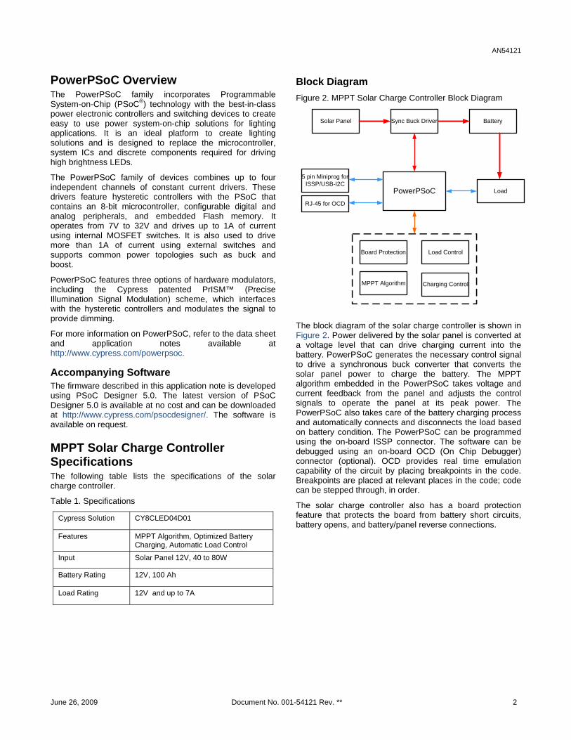
Figure 1 shows the V-I (bold trace) and P-V (dotted trace) characteristics of a typical 75W panel at 25°C and 1000W/m2 of irradiance. A conventional charge controller charges a battery by placing it directly across the solar module. This causes the panel to operate at the battery voltage, thus delivering lower power than what it can actually deliver.
Figure 1. V-I and P-V Characteristics of a 75W Photovoltaic Module
Instead of connecting the battery directly to the photovoltaic modules, Cypress’ MPPT solar charge controller modulates the battery charging current. This is done to operate the module at the voltage where it is capable of producing a maximum power of 75W. This can be done regardless of the value of battery voltage. If the battery voltage is 12V, the voltage at which the maximum power is drawn from the solar module is 17V; the maximum current the module can deliver is 4.5 amperes. This is an increase in battery charging current of up to 1.875 amperes. It significantly improves the ampere-hours delivered to a battery. The greater the difference in the module voltage at which it delivers maximum power and battery voltage, greater is the increase in the battery charging current.
AN54121
PowerPSoC Overview The PowerPSoC family incorporates Programmable System-on-Chip (PSoC®) technology with the best-in-class power electronic controllers and switching devices to create easy to use power system-on-chip solutions for lighting applications. It is an ideal platform to create lighting solutions and is designed to replace the microcontroller, system ICs and discrete components required for driving high brightness LEDs.
The PowerPSoC family of devices combines up to four independent channels of constant current drivers. These drivers feature hysteretic controllers with the PSoC that contains an 8-bit microcontroller, configurable digital and analog peripherals, and embedded Flash memory. It operates from 7V to 32V and drives up to 1A of current using internal MOSFET switches. It is also used to drive more than 1A of current using external switches and supports common power topologies such as buck and boost.
PowerPSoC features three options of hardware modulators, including the Cypress patented PrISM™ (Precise Illumination Signal Modulation) scheme, which interfaces with the hysteretic controllers and modulates the signal to provide dimming.
For more information on PowerPSoC, refer to the data sheet and application notes available at http://www.cypress.com/powerpsoc.
Accompanying Software The firmware described in this application note is developed using PSoC Designer 5.0. The latest version of PSoC Designer 5.0 is available at no cost and can be downloaded at http://www.cypress.com/psocdesigner/. The software is available on request.
MPPT Solar Charge Controller Specifications The following table lists the specifications of the solar charge controller.
Table 1. Specifications
Cypress Solution CY8CLED04D01
Features MPPT Algorithm, Optimized Battery Charging, Automatic Load Control
Input Solar Panel 12V, 40 to 80W
Battery Rating 12V, 100 Ah
Load Rating 12V and up to 7A
Block Diagram Figure 2. MPPT Solar Charge Controller Block Diagram
5 pin Miniprog for ISSP/USB-I2C
RJ-45 for OCD
Solar Panel Battery
PowerPSoC
Sync Buck Driver
Board Protection
MPPT Algorithm
Load
Load Control
Charging Control
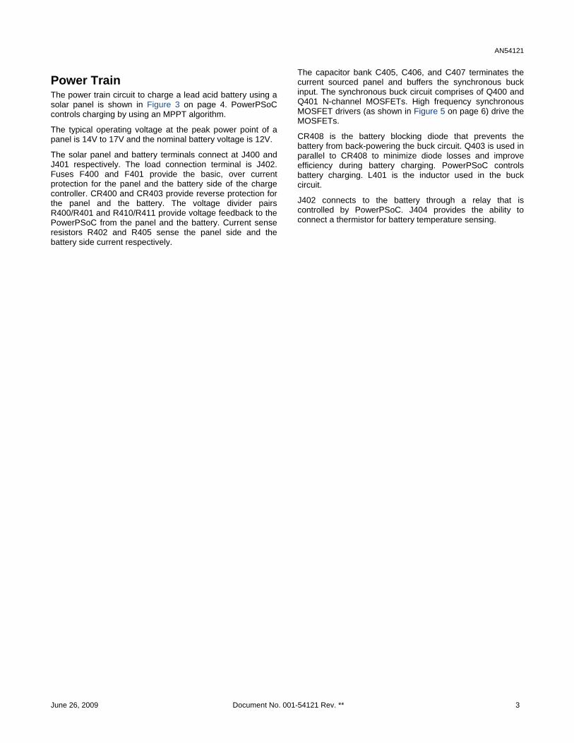
The block diagram of the solar charge controller is shown in Figure 2. Power delivered by the solar panel is converted at a voltage level that can drive charging current into the battery. PowerPSoC generates the necessary control signal to drive a synchronous buck converter that converts the solar panel power to charge the battery. The MPPT algorithm embedded in the PowerPSoC takes voltage and current feedback from the panel and adjusts the control signals to operate the panel at its peak power. The PowerPSoC also takes care of the battery charging process and automatically connects and disconnects the load based on battery condition. The PowerPSoC can be programmed using the on-board ISSP connector. The software can be debugged using an on-board OCD (On Chip Debugger) connector (optional). OCD provides real time emulation capability of the circuit by placing breakpoints in the code. Breakpoints are placed at relevant places in the code; code can be stepped through, in order.
The solar charge controller also has a board protection feature that protects the board from battery short circuits, battery opens, and battery/panel reverse connections.
June 26, 2009 Document No. 001-54121 Rev. ** 2
AN54121
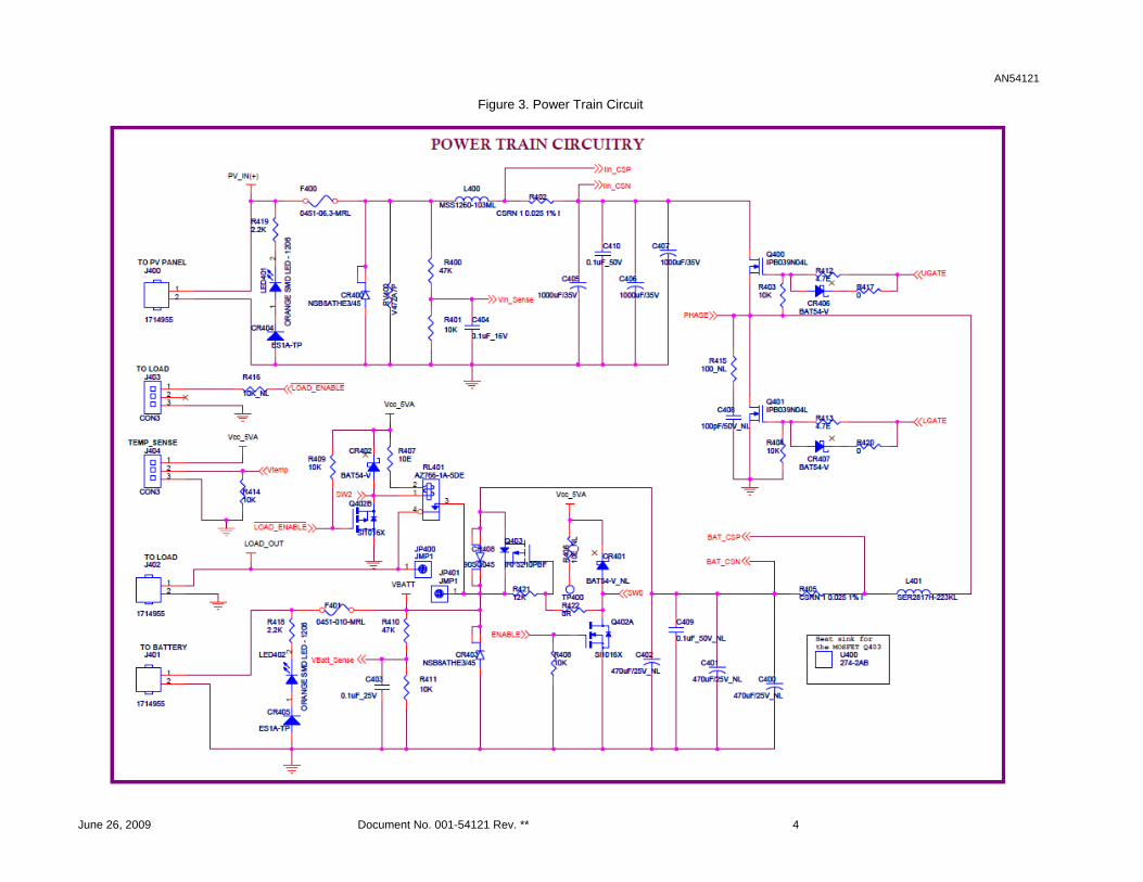
Power Train The power train circuit to charge a lead acid battery using a solar panel is shown in Figure 3 on page 4. PowerPSoC controls charging by using an MPPT algorithm.
The typical operating voltage at the peak power point of a panel is 14V to 17V and the nominal battery voltage is 12V.
The solar panel and battery terminals connect at J400 and J401 respectively. The load connection terminal is J402. Fuses F400 and F401 provide the basic, over current protection for the panel and the battery side of the charge controller. CR400 and CR403 provide reverse protection for the panel and the battery. The voltage divider pairs R400/R401 and R410/R411 provide voltage feedback to the PowerPSoC from the panel and the battery. Current sense resistors R402 and R405 sense the panel side and the battery side current respectively.
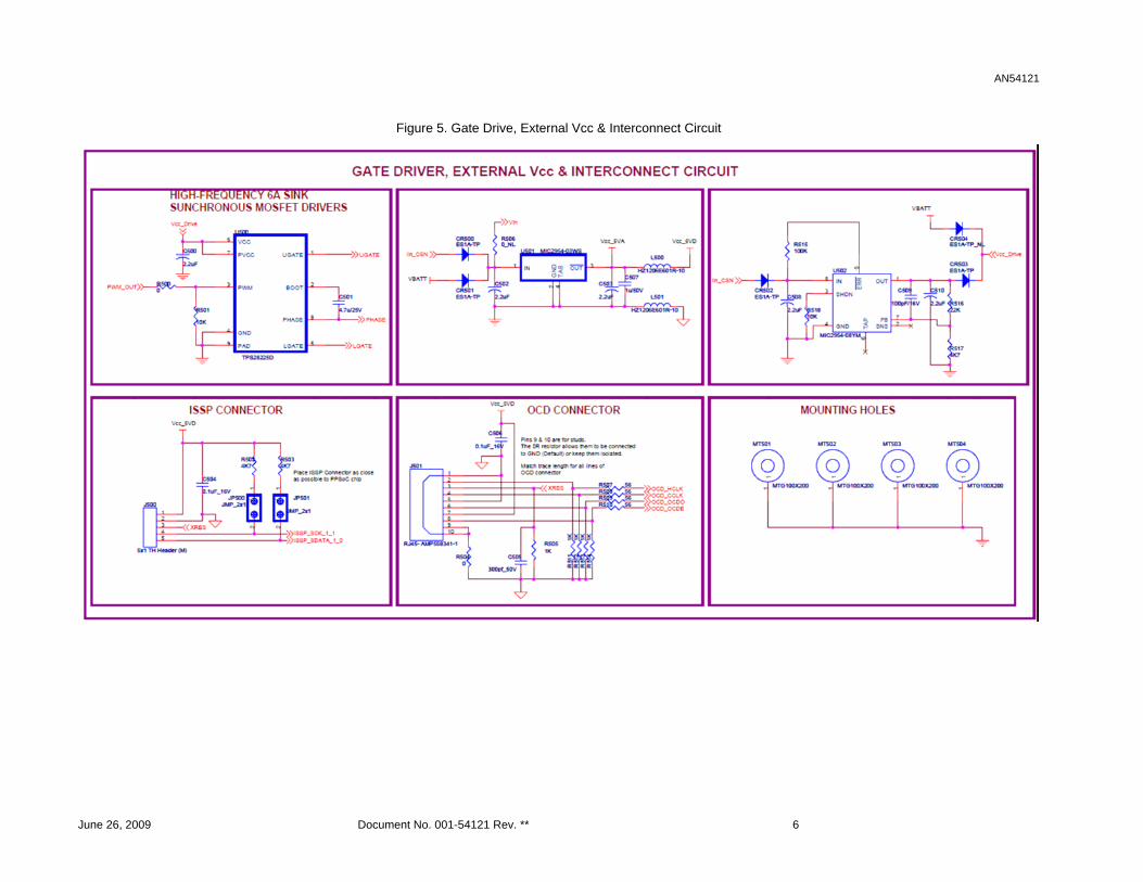
The capacitor bank C405, C406, and C407 terminates the current sourced panel and buffers the synchronous buck input. The synchronous buck circuit comprises of Q400 and Q401 N-channel MOSFETs. High frequency synchronous MOSFET drivers (as shown in Figure 5 on page 6) drive the MOSFETs.
CR408 is the battery blocking diode that prevents the battery from back-powering the buck circuit. Q403 is used in parallel to CR408 to minimize diode losses and improve efficiency during battery charging. PowerPSoC controls battery charging. L401 is the inductor used in the buck circuit.
J402 connects to the battery through a relay that is controlled by PowerPSoC. J404 provides the ability to connect a thermistor for battery temperature sensing.
June 26, 2009 Document No. 001-54121 Rev. ** 3
AN54121
Figure 3. Power Train Circuit
June 26, 2009 Document No. 001-54121 Rev. ** 4
AN54121
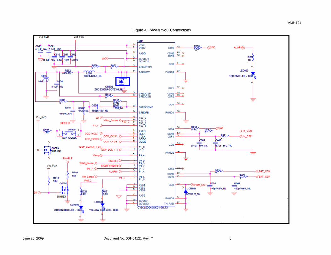
Figure 4. PowerPSoC Connections
June 26, 2009 Document No. 001-54121 Rev. ** 5
AN54121
Figure 5. Gate Drive, External Vcc & Interconnect Circuit
June 26, 2009 Document No. 001-54121 Rev. ** 6
AN54121
PowerPSoC Device The device CY8CLED04DOCD1-56LTXI is the main controller and belongs to the PowerPSoC family. It supports On-Chip Debug (OCD) functionality. The non-OCD part CY8CLED04D01-56LTXI is used if the OCD functionality is not required. PowerPSoC pin connections are shown in Figure 4 on page 5. The nets Iin_CSx and BAT_CSx show current feedback taken from the panel and the battery from the power train circuit. Pins P0.3 and P0.5 monitor battery and panel voltages respectively.
The six PowerPSoC pins with ‘SREG’ in the pin name belong to the 5V built-in switching regulator within the PowerPSoC. This regulator is used to power the PowerPSoC and other devices on the board.
LED600, LED603, and LED604 indicate current operating status and fault conditions that may arise during normal operating conditions.
The controller can be reset using switch SW600.
Load Control The solution features two types of load control: Automatic dusk to dawn
Simultaneous battery charging and load enable
In the dusk to dawn option, the load automatically connects to the battery when the solar panel voltage drops below a certain voltage, indicating sunset or dark conditions. The charge controller disconnects the load from the battery and starts charging the battery when the panel voltage reaches a certain voltage, indicating bright and sunny conditions.
In the second option, the load remains enabled all the time, irrespective of whether the battery is being charged or not.
In both cases, the battery low voltage disconnect function is active and disconnects the load from the battery when the voltage is below 10.8V. This helps to prevent the battery from deep discharge and improves battery life.
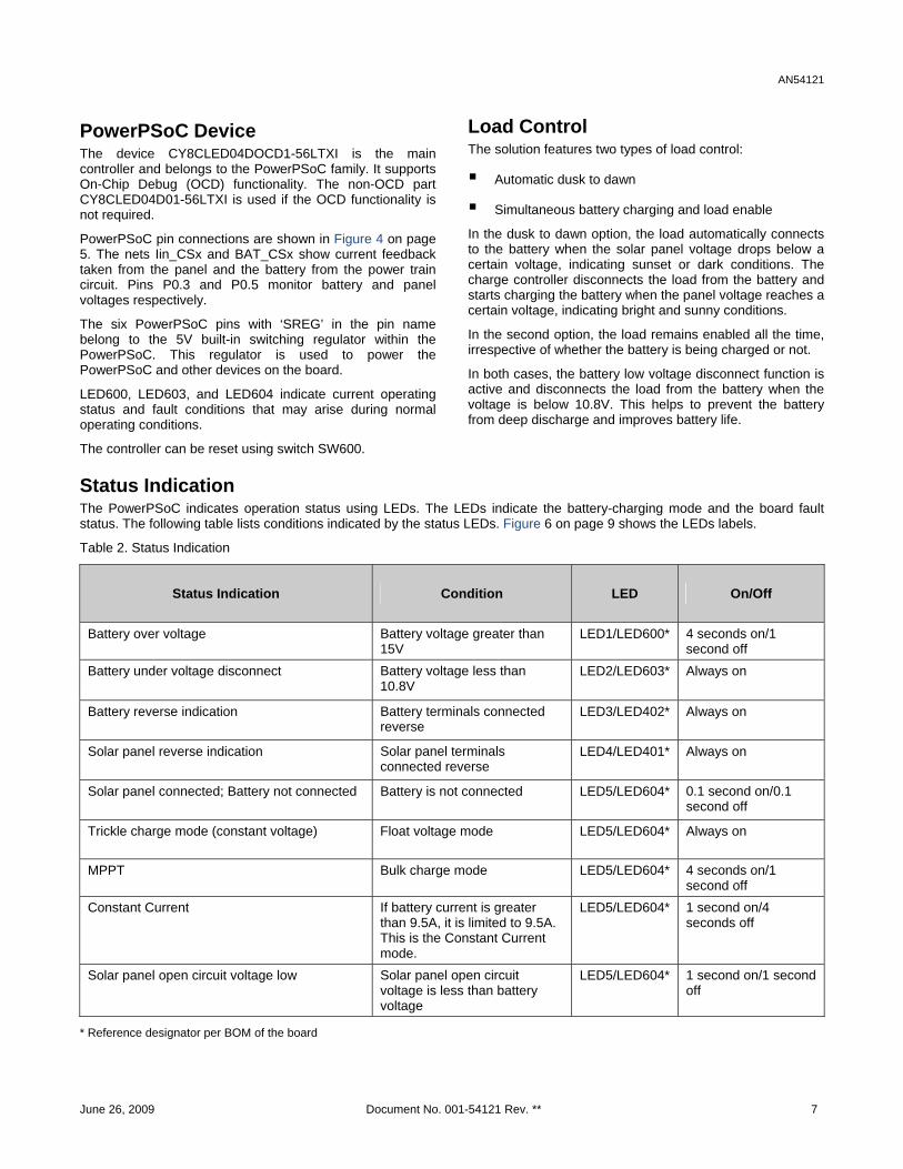
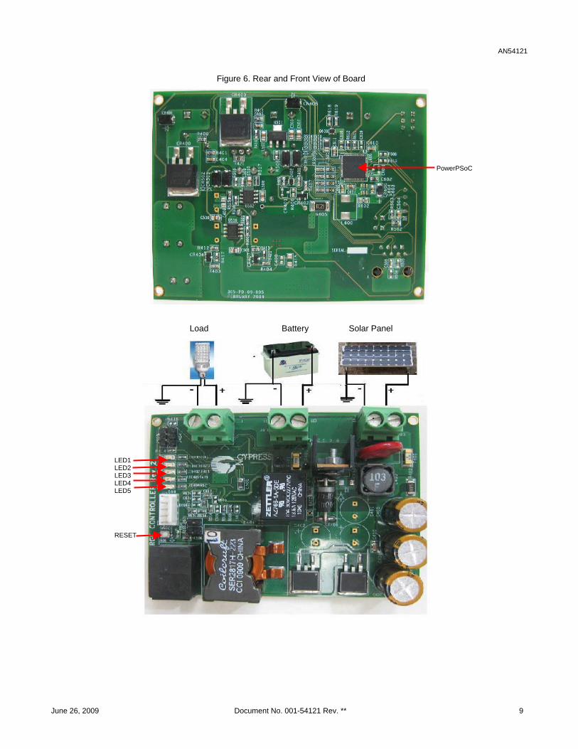
Status Indication The PowerPSoC indicates operation status using LEDs. The LEDs indicate the battery-charging mode and the board fault status. The following table lists conditions indicated by the status LEDs. Figure 6 on page 9 shows the LEDs labels.
Table 2. Status Indication
Status Indication Condition LED On/Off
Battery over voltage Battery voltage greater than 15V
LED1/LED600* 4 seconds on/1 second off
Battery under voltage disconnect Battery voltage less than 10.8V
LED2/LED603* Always on
Battery reverse indication Battery terminals connected reverse
LED3/LED402* Always on
Solar panel reverse indication Solar panel terminals connected reverse
LED4/LED401* Always on
Solar panel connected; Battery not connected Battery is not connected LED5/LED604* 0.1 second on/0.1 second off
Trickle charge mode (constant voltage) Float voltage mode LED5/LED604* Always on
MPPT Bulk charge mode LED5/LED604* 4 seconds on/1 second off
Constant Current If battery current is greater than 9.5A, it is limited to 9.5A. This is the Constant Current mode.
LED5/LED604* 1 second on/4 seconds off
Solar panel open circuit voltage low Solar panel open circuit voltage is less than battery voltage
LED5/LED604* 1 second on/1 second off
* Reference designator per BOM of the board
June 26, 2009 Document No. 001-54121 Rev. ** 7
AN54121
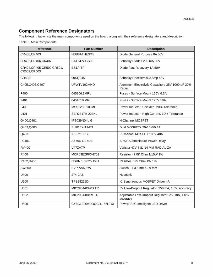
Component Reference Designators The following table lists the main components used on the board along with their reference designators and description.
Table 3. Main Components
Reference Part Number Description CR400,CR403 NSB8ATHE3/45 Diode General Purpose 8A 50V
CR402,CR406,CR407 BAT54-V-GS08 Schottky Diodes 200 mA 30V
CR404,CR405,CR500,CR501, CR502,CR503
ES1A-TP Diode Fast Recovery 1A 50V
CR408 90SQ045 Schottky Rectifiers 9.0 Amp 45V
C405,C406,C407 UFW1V102MHD Aluminum Electrolytic Capacitors 35V 1000 µF 20% Radial
F400 045106.3MRL Fuses - Surface Mount 125V 6.3A
F401 0451010.MRL Fuses - Surface Mount 125V 10A
L400 MSS1260-103ML Power Inductor, Shielded, 20% Tolerance
L401 SER2817H-223KL Power Inductor, High Current, 10% Tolerance
Q400,Q401 IPB039N04L G N-Channel MOSFET
Q402,Q600 SI1016X-T1-E3 Dual MOSFETs 20V 0.6/0.4A
Q403 IRF5210PBF P-Channel MOSFET 100V 40A
RL401 AZ766-1A-5DE SPST Subminiature Power Relay
RV400 V47ZA7P Varistor 47V 8.8J 14 MM RADIAL ZA
R400 MCR03EZPFX4702 Resistor 47.0K Ohm 1/10W 1%
R402,R405 CSRN 1 0.025 1% I Resistor .025 Ohm 1W 1%
SW600 EVP-AA602W Switch LT 3.5 mmX2.9 mm
U400 274-2AB Heatsink
U500 TPS28225D IC Synchronous MOSFET Driver 4A
U501 MIC2954-03WS TR 5V Low-Dropout Regulator, 250 mA, 1.0% accuracy
U502 MIC2954-08YM TR Adjustable Low-Dropout Regulator, 250 mA, 1.0% accuracy
U600 CY8CLED04DDOCD1-56LTXI PowerPSoC Intelligent LED Driver
June 26, 2009 Document No. 001-54121 Rev. ** 8
AN54121
Figure 6. Rear and Front View of Board
PowerPSoC
Load Battery Solar Panel
LED1 LED2 LED3 LED4 LED5
RESET
June 26, 2009 Document No. 001-54121 Rev. ** 9
AN54121
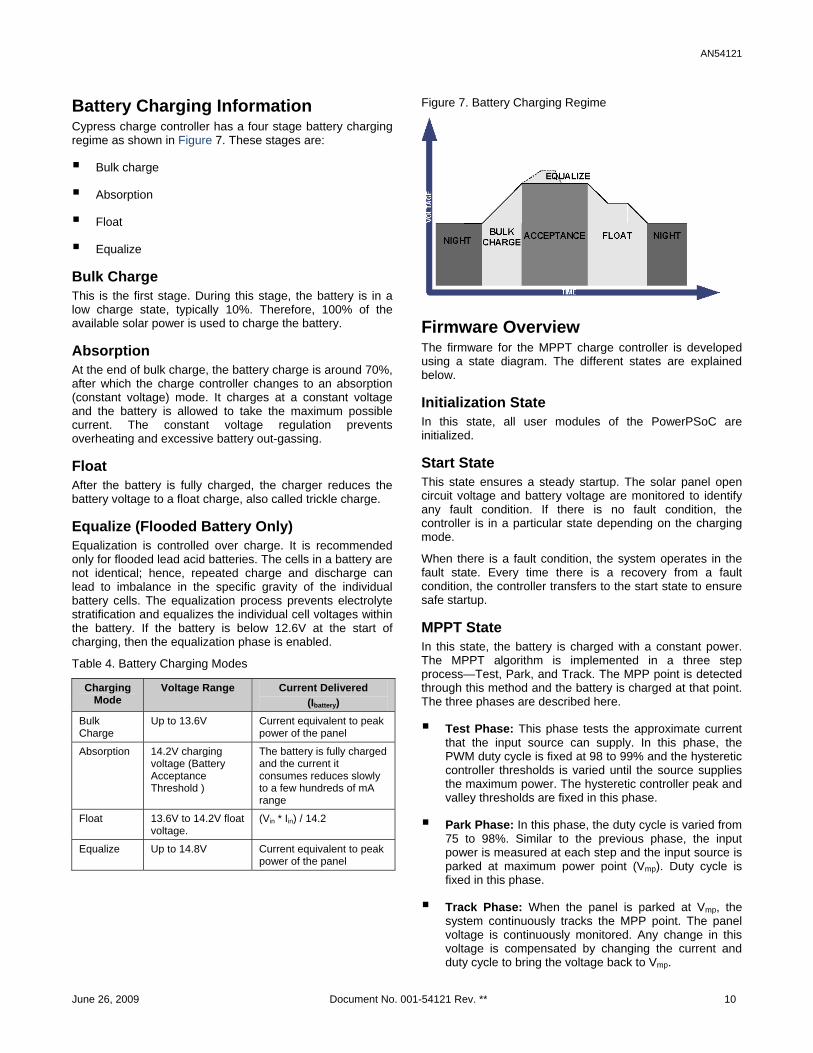
Battery Charging Information Cypress charge controller has a four stage battery charging regime as shown in Figure 7. These stages are:
Bulk charge
Absorption
Float
Equalize Bulk Charge This is the first stage. During this stage, the battery is in a low charge state, typically 10%. Therefore, 100% of the available solar power is used to charge the battery.
Absorption At the end of bulk charge, the battery charge is around 70%, after which the charge controller changes to an absorption (constant voltage) mode. It charges at a constant voltage and the battery is allowed to take the maximum possible current. The constant voltage regulation prevents overheating and excessive battery out-gassing.
Float After the battery is fully charged, the charger reduces the battery voltage to a float charge, also called trickle charge.
Equalize (Flooded Battery Only) Equalization is controlled over charge. It is recommended only for flooded lead acid batteries. The cells in a battery are not identical; hence, repeated charge and discharge can lead to imbalance in the specific gravity of the individual battery cells. The equalization process prevents electrolyte stratification and equalizes the individual cell voltages within the battery. If the battery is below 12.6V at the start of charging, then the equalization phase is enabled.
Table 4. Battery Charging Modes
Charging Mode
Voltage Range Current Delivered (Ibattery)
Bulk Charge
Up to 13.6V Current equivalent to peak power of the panel
Absorption 14.2V charging voltage (Battery Acceptance Threshold )
The battery is fully charged and the current it consumes reduces slowly to a few hundreds of mA range
Float 13.6V to 14.2V float voltage.
(Vin * Iin) / 14.2
Equalize Up to 14.8V Current equivalent to peak power of the panel
Figure 7. Battery Charging Regime
Firmware Overview The firmware for the MPPT charge controller is developed using a state diagram. The different states are explained below.
Initialization State In this state, all user modules of the PowerPSoC are initialized.
Start State This state ensures a steady startup. The solar panel open circuit voltage and battery voltage are monitored to identify any fault condition. If there is no fault condition, the controller is in a particular state depending on the charging mode.
When there is a fault condition, the system operates in the fault state. Every time there is a recovery from a fault condition, the controller transfers to the start state to ensure safe startup.
MPPT State In this state, the battery is charged with a constant power. The MPPT algorithm is implemented in a three step process—Test, Park, and Track. The MPP point is detected through this method and the battery is charged at that point. The three phases are described here.
Test Phase: This phase tests the approximate current that the input source can supply. In this phase, the PWM duty cycle is fixed at 98 to 99% and the hysteretic controller thresholds is varied until the source supplies the maximum power. The hysteretic controller peak and valley thresholds are fixed in this phase.
Park Phase: In this phase, the duty cycle is varied from 75 to 98%. Similar to the previous phase, the input power is measured at each step and the input source is parked at maximum power point (Vmp). Duty cycle is fixed in this phase.
Track Phase: When the panel is parked at Vmp, the system continuously tracks the MPP point. The panel voltage is continuously monitored. Any change in this voltage is compensated by changing the current and duty cycle to bring the voltage back to Vmp.
June 26, 2009 Document No. 001-54121 Rev. ** 10
AN54121
Not every battery needs an equalization phase during charging. The phase is shown in Figure 7 on page 10 and is a part of the MPPT state.
The decision to charge the battery to the equalization voltage depends on the no load battery voltage at the start of charge. Only if the voltage at the start of charge (SoC) is less than 12.6V, the battery is charged to 14.8V (on charge terminal voltage).
Batteries with an open circuit voltage of 12.8V to 13V are at 100% SoC. They are used only up to 30% Depth of Discharge (DoD) at the point when the open circuit voltage is 12.6V.
After the battery reaches this voltage, charging is continued in the MPPT state for one hour. The terminal voltage rises in this period. If the terminal voltage reaches 15V, which is the over voltage during this time, the operation switches to the constant voltage mode. Essentially, the battery charges from 14.8V to 15V or for one hour, whichever occurs first.
Constant Current (CC) State In this state, the battery is charged with the maximum current (Imax) possible for the system. This current threshold is fixed by the firmware. When operating in the MPPT mode, if the battery current goes beyond Imax, the controller switches to constant current mode. In this mode, the battery current is limited by fixing the peak and valley thresholds. The average current threshold is set to 9.5 amperes in the firmware assuming a 100 Ah (ampere-hour) battery.
Trickle Charge/Constant Voltage (CV) State After the battery reaches the Trickle Charge threshold (Vbat_max) in the MPPT state, it switches to Constant Voltage state. This state compensates for the self-discharge of the battery. It is divided into two phases.
Absorption: In this phase, the battery is charged at a constant voltage and is allowed to take whatever current it can. The constant voltage regulation prevents heating and excessive battery gassing.
Float: In this phase, the battery is fully charged; the charger reduces the battery voltage to a float charge voltage. The battery takes current in the order of few 100 mA. The charge controller continues to operate in this phase until the battery reaches the battery Over-Voltage Threshold (Vbat_OV)
Load Enable State In this state, the difference between the solar panel open circuit voltage and the battery voltage is less than Vdiff. This parameter is hard coded and can be changed by firmware. If the battery voltage is greater than minimum battery voltage capable of driving the load (Vbat_min) which is defined as 10.8V then the load is turned on. This parameter is also hardcoded in the firmware and can be changed. The LOAD_ENABLE pin is set low enabling the relay and hence energizing the load.
Status Update State The current status of the system is recorded in this state. The execution shifts to this state after every fixed duration, which is set by the firmware. Battery temperature is measured enabling thermal compensation. The parameters recorded are:
1. Fault History
2. AH/WH Meter
3. System Status Indicator
4. Input Voltage
5. Output Voltage
6. Load Current
7. Battery Charging Current
Parameters 3 to 7 are recorded every fixed time period (TUPDATE) and over written after the assigned memory is exhausted. Memory location for parameters 1 and 2 are fixed. Their values are updated every cycle.
Fault State There are various fault conditions for the system.
Battery Over Voltage (BOV): This fault occurs when the battery voltage exceeds the over voltage threshold.
Exit Condition: In a no load condition, the controller waits for the battery voltage to reduce below a set threshold through self discharge. When the voltage falls below the threshold, the red LED is turned off, the BOV flag is cleared, and the controller returns to the start state.
In a loaded condition, the battery continues driving the load and the controller does not enter the fault state.
No Battery Connected (NBC): This fault occurs when no battery is connected to the charge controller.
Exit Condition: The controller keeps polling the battery voltage until the battery is detected. It then switches off the indication LED, clears the flag, and returns to the start state.
June 26, 2009 Document No. 001-54121 Rev. ** 11
AN54121
Battery Under Voltage (BUV): This fault occurs when the battery voltage is below the minimum threshold required to power the load.
Exit condition: The controller keeps polling for the solar panel open circuit voltage and battery voltage. It exits fault state when the solar panel open circuit voltage is sufficient to charge the battery and goes back to start state. It clears the BUV flag and switches off the green LED after the battery is sufficiently charged.
Panel Voltage Low (PVL): This fault occurs when the difference between the solar panel open circuit voltage and the battery voltage is less than Vdiff (0.5V). This indicates that the solar panel is not capable of charging the battery.
Exit condition: The controller keeps polling for solar panel open circuit voltage and battery voltage. When the solar panel open circuit voltage is greater than the battery voltage by at least Vdiff, it clears the flag and returns to the start state.
Wiring Details
Input Power Supply The power supply can be from a DC or a solar panel. This board can be powered from a solar panel rated at 40W to 80W.
When using an external power supply, the voltage should be between 14V to 17V and current is limited to a maximum of 7 amperes.
When connecting the solar panel of 80W or less, wire of cross-section area 2.5 mm2 thicknesses or greater are used.
Wire length is restricted to 5m.
Positive and negative terminals are connected as shown in Figure 6 on page 9.
Battery This solar charge controller is designed for a 12V lead acid battery.
When connecting the battery, wire of cross-section area 4 mm2 is used.
Wire length is kept short, less than 1m.
Positive and negative terminals are connected as shown in Figure 6 on page 9.
Load When connecting the load, a wire of cross-section area
2.5 mm2 or greater is used.
Wire length should be as short as possible to minimize power losses in the wire.
Positive and negative terminals are connected as shown in Figure 6 on page 9.
Power up Instructions Connect the panel and the battery.. The system starts
charging the battery as soon as the solar panel is connected.
The system operates in different charging modes based on the battery no load voltage. It is in fault condition if there is any error in the system. Table 2 on page 6 lists the various status indications.
Advantages of Cypress’ Solution Cypress’ MPPT solar charge controller solution is built
on a fully flexible PowerPSoC hardware platform.
The solution implements a smart maximum peak power tracking algorithm that tracks the peak power point of a solar panel irrespective of operating conditions. This ensures power gain when compared to conventional charge controllers.
It charges a lead acid battery using an optimized charging regime that improves battery life.
It improves the life span of the battery by preventing over charging.
It implements a low battery disconnect feature to prevent the battery from discharging below a certain charge state. This helps the battery to retain its full capacity.
It operates from 40W to 80W rated solar panel.
It provides protection from panel reverse and battery reverse conditions.
Summary This application note provides an overview of Cypress’ MPPT Solar Charge Controller solution implemented with PowerPSoC.
June 26, 2009 Document No. 001-54121 Rev. ** 12
AN54121
About the Authors Name: Anshul Gulati
Title: Product Marketing Engineer 2
Background: Anshul Gulati holds a Bachelors degree in Electrical and Electronics from BITS – Pilani, India. Her previous experience is in embedded systems design. She is currently working on PowerPSoC solutions.
Contact: [email protected]
Name: Srinivas NVNS
Title: Applications Engineer Senior
Background: Srinivas holds a Master’s degree in Power and Control from Indian Institute of Technology Kanpur, India. He enjoys working in power electronics and embedded systems design. He is currently working on PowerPSoC solutions.
Contact: [email protected]
June 26, 2009 Document No. 001-54121 Rev. ** 13
AN54121
Document History Document Title: Implementation of MPPT Solar Charge Controller with PowerPSoC®
Document Number: 001-54121
Revision ECN Orig. of Change
Submission Date
Description of Change
** 2722473 GULA/SNVN 06/23/09 New application note
PSoC and PowerPSoC are registered trademarks and PrISM is a trademark of Cypress Semiconductor Corp. All other trademarks or registered trademarks referenced herein are the property of their respective owners.
Cypress Semiconductor 198 Champion Court
San Jose, CA 95134-1709 Phone: 408-943-2600
Fax: 408-943-4730 http://www.cypress.com/
© Cypress Semiconductor Corporation, 2009. The information contained herein is subject to change without notice. Cypress Semiconductor Corporation assumes no responsibility for the use of any circuitry other than circuitry embodied in a Cypress product. Nor does it convey or imply any license under patent or other rights. Cypress products are not warranted nor intended to be used for medical, life support, life saving, critical control or safety applications, unless pursuant to an express written agreement with Cypress. Furthermore, Cypress does not authorize its products for use as critical components in life-support systems where a malfunction or failure may reasonably be expected to result in significant injury to the user. The inclusion of Cypress products in life-support systems application implies that the manufacturer assumes all risk of such use and in doing so indemnifies Cypress against all charges.
This Source Code (software and/or firmware) is owned by Cypress Semiconductor Corporation (Cypress) and is protected by and subject to worldwide patent protection (United States and foreign), United States copyright laws and international treaty provisions. Cypress hereby grants to licensee a personal, non-exclusive, non-transferable license to copy, use, modify, create derivative works of, and compile the Cypress Source Code and derivative works for the sole purpose of creating custom software and or firmware in support of licensee product to be used only in conjunction with a Cypress integrated circuit as specified in the applicable agreement. Any reproduction, modification, translation, compilation, or representation of this Source Code except as specified above is prohibited without the express written permission of Cypress.
Disclaimer: CYPRESS MAKES NO WARRANTY OF ANY KIND, EXPRESS OR IMPLIED, WITH REGARD TO THIS MATERIAL, INCLUDING, BUT NOT LIMITED TO, THE IMPLIED WARRANTIES OF MERCHANTABILITY AND FITNESS FOR A PARTICULAR PURPOSE. Cypress reserves the right to make changes without further notice to the materials described herein. Cypress does not assume any liability arising out of the application or use of any product or circuit described herein. Cypress does not authorize its products for use as critical components in life-support systems where a malfunction or failure may reasonably be expected to result in significant injury to the user. The inclusion of Cypress’ product in a life-support systems application implies that the manufacturer assumes all risk of such use and in doing so indemnifies Cypress against all charges.
Use may be limited by and subject to the applicable Cypress software license agreement.
June 26, 2009 Document No. 001-54121 Rev. ** 14
Related Documents


