Hassib Fowad Rezai MPLS VPN In a Service Provider Network Bachelor of Engineering Information and Communication Technology 2021

Welcome message from author
This document is posted to help you gain knowledge. Please leave a comment to let me know what you think about it! Share it to your friends and learn new things together.
Transcript
Hassib Fowad Rezai
MPLS VPN In a Service Provider Network
Bachelor of Engineering
Information and Communication Technology
2021
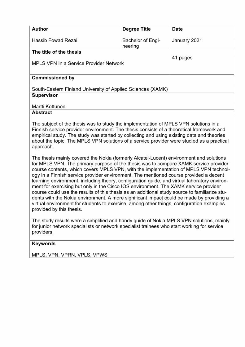
Author
Degree Title
Date
Hassib Fowad Rezai Bachelor of Engi-neering
January 2021
The title of the thesis MPLS VPN In a Service Provider Network
41 pages
Commissioned by South-Eastern Finland University of Applied Sciences (XAMK)
Supervisor Martti Kettunen
Abstract The subject of the thesis was to study the implementation of MPLS VPN solutions in a Finnish service provider environment. The thesis consists of a theoretical framework and empirical study. The study was started by collecting and using existing data and theories about the topic. The MPLS VPN solutions of a service provider were studied as a practical approach. The thesis mainly covered the Nokia (formerly Alcatel-Lucent) environment and solutions for MPLS VPN. The primary purpose of the thesis was to compare XAMK service provider course contents, which covers MPLS VPN, with the implementation of MPLS VPN technol-ogy in a Finnish service provider environment. The mentioned course provided a decent learning environment, including theory, configuration guide, and virtual laboratory environ-ment for exercising but only in the Cisco IOS environment. The XAMK service provider course could use the results of this thesis as an additional study source to familiarize stu-dents with the Nokia environment. A more significant impact could be made by providing a virtual environment for students to exercise, among other things, configuration examples provided by this thesis. The study results were a simplified and handy guide of Nokia MPLS VPN solutions, mainly for junior network specialists or network specialist trainees who start working for service providers.
Keywords MPLS, VPN, VPRN, VPLS, VPWS
Tekijä/Tekijät
Tutkinto
Aika
Hassib Fowad Rezai Insinööri (AMK) Tammikuu 2021
Opinnäytetyön nimi MPLS VPN operaattorin verkossa
41 sivua
Toimeksiantaja Kaakkois-Suomen ammattikorkeakoulu (XAMK)
Ohjaaja Martti Kettunen
Tiivistelmä Opinnäytetyö koostuu teoreettisesta viitekehyksestä sekä empiirisestä tutkimuksesta. Tut-kimus aloitettiin keräämällä ja käyttämällä olemassa olevia tietoja ja teorioita aiheesta. Erään palvelutarjoajan MPLS VPN-ratkaisuja tutkittiin käytännönläheisenä lähestymista-pana. Opinnäytetyön aiheena oli tutkia MPLS VPN -ratkaisujen toteutusta eräässä suomalaisessa palveluntarjoajan ympäristössä. Tämän tutkimuksen päätarkoitus oli verrata XAMK:n palve-luntarjoajan kurssisisältöä, jonka aiheena on pääsääntöisesti MPLS VPN teknologia Cisco IOS ympäristössä, MPLS VPN -teknologian käyttöönottoon suomalaisessa palveluntarjo-ajan verkossa, jossa on käytetty Nokian MPLS VPN ratkaisuja. Kurssi tarjoaa kunnollisen oppimisympäristön, mukaan lukien teoriaa, konfiguraatio oppaat, ja virtuaalinen ympäristö harjoittelua varten, mutta nämä koskee vain Cisco IOS-ympäristöä. Mainittu kurssi voisi käyttää tämän tutkimuksen tulokset opiskelijoille luettavaksi lisälähteenä tutustumaan No-kian ympäristöön. Merkittävämpi vaikutus voidaan tuoda tarjoamalla virtuaaliympäristöä, jossa opiskelijat voivat harjoitella mm. tämän tutkimuksen esittämiä konfiguraatioesimerk-kejä. Lisäksi tutkimuksen tulos on yksinkertaistettu ja kätevä opas Nokian MPLS VPN -rat-kaisuista, pääasiassa junior tietoliikenneasiantuntijoille tai harjoittelijoille, jotka aloittavat uransa palveluntarjoajien ympäristössä.
Asiansanat MPLS, VPN, VPRN, VPLS, VPWS
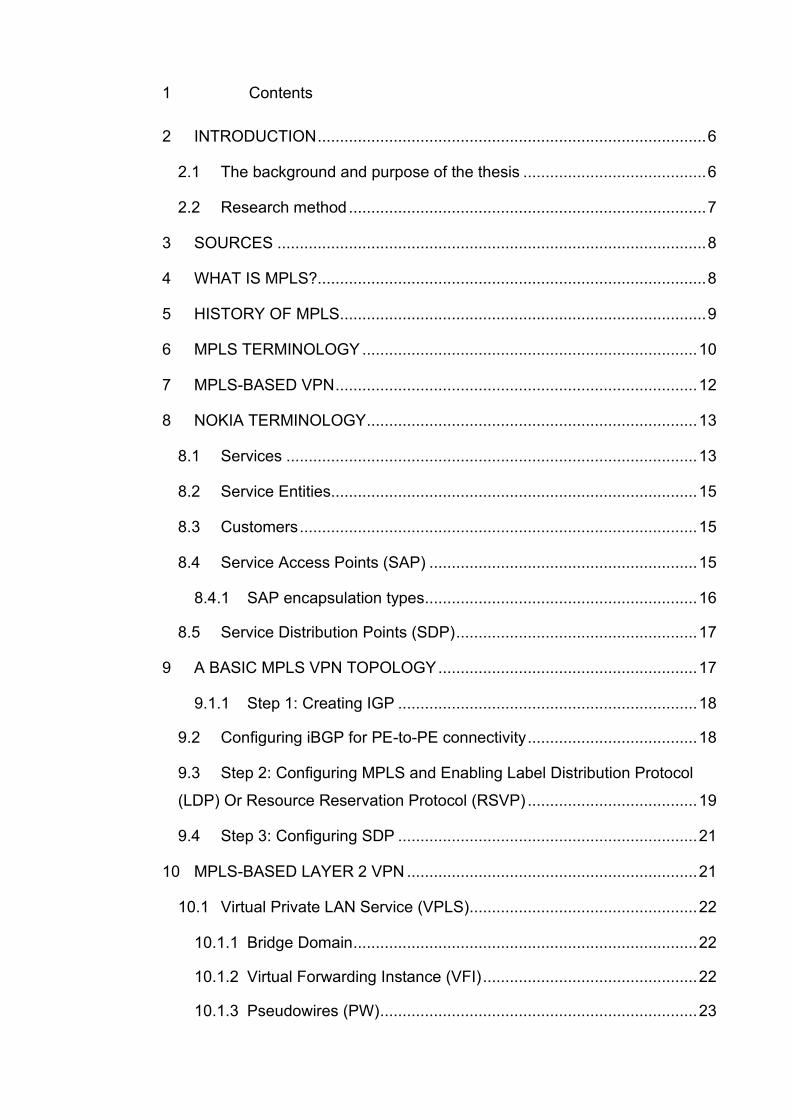
1 Contents
2 INTRODUCTION ....................................................................................... 6
2.1 The background and purpose of the thesis ......................................... 6
2.2 Research method ................................................................................ 7
3 SOURCES ................................................................................................ 8
4 WHAT IS MPLS?....................................................................................... 8
5 HISTORY OF MPLS .................................................................................. 9
6 MPLS TERMINOLOGY ........................................................................... 10
7 MPLS-BASED VPN ................................................................................. 12
8 NOKIA TERMINOLOGY .......................................................................... 13
8.1 Services ............................................................................................ 13
8.2 Service Entities.................................................................................. 15
8.3 Customers ......................................................................................... 15
8.4 Service Access Points (SAP) ............................................................ 15
8.4.1 SAP encapsulation types............................................................. 16
8.5 Service Distribution Points (SDP) ...................................................... 17
9 A BASIC MPLS VPN TOPOLOGY .......................................................... 17
9.1.1 Step 1: Creating IGP ................................................................... 18
9.2 Configuring iBGP for PE-to-PE connectivity ...................................... 18
9.3 Step 2: Configuring MPLS and Enabling Label Distribution Protocol
(LDP) Or Resource Reservation Protocol (RSVP) ...................................... 19
9.4 Step 3: Configuring SDP ................................................................... 21
10 MPLS-BASED LAYER 2 VPN ................................................................. 21
10.1 Virtual Private LAN Service (VPLS) ................................................... 22
10.1.1 Bridge Domain ............................................................................. 22
10.1.2 Virtual Forwarding Instance (VFI) ................................................ 22
10.1.3 Pseudowires (PW) ....................................................................... 23
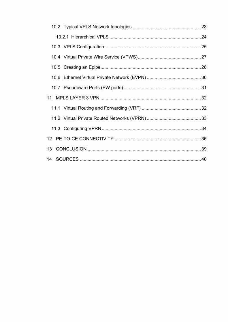
10.2 Typical VPLS Network topologies ..................................................... 23
10.2.1 Hierarchical VPLS ....................................................................... 24
10.3 VPLS Configuration ........................................................................... 25
10.4 Virtual Private Wire Service (VPWS) ................................................. 27
10.5 Creating an Epipe.............................................................................. 28
10.6 Ethernet Virtual Private Network (EVPN) .......................................... 30
10.7 Pseudowire Ports (PW ports) ............................................................ 31
11 MPLS LAYER 3 VPN .............................................................................. 32
11.1 Virtual Routing and Forwarding (VRF) .............................................. 32
11.2 Virtual Private Routed Networks (VPRN) .......................................... 33
11.3 Configuring VPRN ............................................................................. 34
12 PE-TO-CE CONNECTIVITY ................................................................... 36
13 CONCLUSION ........................................................................................ 39
14 SOURCES .............................................................................................. 40
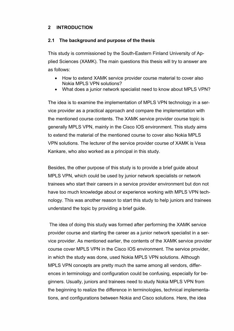
2 INTRODUCTION
2.1 The background and purpose of the thesis
This study is commissioned by the South-Eastern Finland University of Ap-
plied Sciences (XAMK). The main questions this thesis will try to answer are
as follows:
• How to extend XAMK service provider course material to cover also Nokia MPLS VPN solutions?
• What does a junior network specialist need to know about MPLS VPN?
The idea is to examine the implementation of MPLS VPN technology in a ser-
vice provider as a practical approach and compare the implementation with
the mentioned course contents. The XAMK service provider course topic is
generally MPLS VPN, mainly in the Cisco IOS environment. This study aims
to extend the material of the mentioned course to cover also Nokia MPLS
VPN solutions. The lecturer of the service provider course of XAMK is Vesa
Kankare, who also worked as a principal in this study.
Besides, the other purpose of this study is to provide a brief guide about
MPLS VPN, which could be used by junior network specialists or network
trainees who start their careers in a service provider environment but don not
have too much knowledge about or experience working with MPLS VPN tech-
nology. This was another reason to start this study to help juniors and trainees
understand the topic by providing a brief guide.
The idea of doing this study was formed after performing the XAMK service
provider course and starting the career as a junior network specialist in a ser-
vice provider. As mentioned earlier, the contents of the XAMK service provider
course cover MPLS VPN in the Cisco IOS environment. The service provider,
in which the study was done, used Nokia MPLS VPN solutions. Although
MPLS VPN concepts are pretty much the same among all vendors, differ-
ences in terminology and configuration could be confusing, especially for be-
ginners. Usually, juniors and trainees need to study Nokia MPLS VPN from
the beginning to realize the difference in terminologies, technical implementa-
tions, and configurations between Nokia and Cisco solutions. Here, the idea
was to integrate Nokia MPLS VPN solutions in the XAMK service provider
course.
2.2 Research method
The research approach will be design-based research. According to Arthur
Backer & Dolley van Eerde (2013), design-based research is worth knowing
about, especially for students who will become teachers or researchers in ed-
ucation: Design-based research is claimed to have the potential to bridge the
gap between educational practice and theory because it aims both at develop-
ing ideas about domain-specific learning and the means that are designed to
support that learning. DBR thus produces useful products (e.g., educational
materials) and accompanying scientific insights into how these products can
be used in education.
This study was started by briefly going through the theory of MPLS as well as
MPLS VPN techniques. In this part, the idea was to use the existing data from
approved sources to provide a background and definition of the topic. Next,
the applications of the MPLS VPN in a service provider backbone network
were studied. This part was accomplished by examining the different tech-
niques such as fiber optic, copper, and mobile connection, which use MPLS
VPN technology. The provider core, provider edge, and customer edge were
studied.
Several credible sources were used to complete the study alongside studying
applications and deployments of MPLS VPN in the service provider network.
The XAMK service provider course and Nokia documentation contents were
among the most used source for this study. Additionally, there were several
sessions with network specialists and solutions specialists from the service
provider for using their knowledge and experiments of working with the MPLS
VPN to promote the study. And finally, some labs in the virtual environment
were built to put the theory into practice.
The study started in early May 2020, and the goal was to finish it before the
end of the year 2020.
3 SOURCES
MPLS VPN is a topic that requires detailed explanations because many con-
cepts and techniques need to be understood. That is why even some experts
in this field struggle to gain expertise in it. Most of the MPLS VPN sources are
vendor-based guides focusing on their terminology, techniques, and operating
systems. Those detailed guides are usually hard to understand for newcomers
in the field. Here the goal is not to underrate those detailed and comprehen-
sive sources but to provide a simplified reference for understanding the most
necessary techniques and terminologies of the topic for a beginner.
Nokia documentation was widely used for the theory part as well as configura-
tion examples. Cisco documentation and guides were other excellent sources
for this topic. The MPLS and VPN architecture book published by Cisco and
the MPLS-Enabled Applications book were among other sources. The XAMK
Service Provider course materials, guides, and labs were among other credi-
ble sources for this study.
4 WHAT IS MPLS?
A traditional IP packet is forwarded based on the destination IP addresses.
The IP address is contained in the network layer header. The database
needed for delivering information is provided either by network layer routing
protocols like BGP, IS-IS, OSPF, or static routing. A router analyzes the IP
packet at each hop independently in the network and forwards it based on the
destination IP address (Guichard & Pepelnjak, 2009, 2009.)
Traditional IP routing has several well-known limitations, ranging from scalabil-
ity issues to poor support or traffic engineering and poor integration with Layer
2 backbones already existing in large service provider networks. With the
rapid growth of the Internet and the establishment of IP as the Layer 3 proto-
col of choice in most environments, the drawbacks of traditional IP routing
have become more and more apparent (Guichard & Pepelnjak, 2009.)
Multiprotocol Label Switching is a label switching technology that provides the
ability to set up connection-oriented paths over a connectionless IP network.
MPLS enables routers to forward traffic based on a simple label embedded
into the packet header. In other words, the packets are identified by a label in-
serted into each packet. A router examines the label to determine the next hop
for the packet, saving time for router address lookups to the next node when
forwarding packets. MPLS is not enabled by default and must be explicitly en-
abled. MPLS is independent of any routing protocol but is considered multipro-
tocol because it works with the IP, ATM, and Frame Relay network protocols
(Nokia, 2017.)
MPLS was created to combine the benefits of connectionless Layer 3 routing
and forwarding with connection-oriented Layer 2 forwarding. MPLS separates
the control plane, where Layer 3 protocols establish the paths used for packet
forwarding and the data plane where Layer 2 label switched paths forward
data packets across the MPLS infrastructure. Besides IP routing, MPLS also
supports IP multicast routing and quality of service (QoS) extensions (Guich-
ard & Pepelnjak, 2009.)
5 HISTORY OF MPLS
Internet Engineering Task Force (IETF) organized the first working group
meeting for developing Multiprotocol Label Switching (MPLS) technology in
1997. Here are the significant problems that MPLS was supposed to solve:
• Scalability of network layer routing: Using labels to aggregate for-
warding information while working in the presence of routing hierar-
chies.
• Greater flexibility in delivering routing services: Using labels to
identify traffic to receive unique benefits, e.g., Quality of Services
(QoS), and using labels to provide forwarding along an explicit path dif-
ferent from those constructed by destination-based forwarding.
• Increasing network performance: Using the label-swapping paradigm
to optimize network performance.
• Simplify integration of routers with cell switching based technolo-
gies: Making a better integration of Asynchronous Transport Mode
(ATM) with Internet Protocol (IP) by having a single control plane spans
both ATM switch and routers (Minei & Lucek, 2011)
After initially launched, MPLS usage was extended to other applications such
as Circuit Cross-Connect (CCC), ATM, and Frame Relay services over
IP/MPLS infrastructure, Layer 2, and Layer 3 VPNs, and Virtual Private LAN
Services (VPLS). Later, the expanding of MPLS into the access network and
bringing Seamless MPLS significantly progressed this technique. MPLS was
initially designed for Service providers, but later it was used mainly in the en-
terprise environment. MPLS is also used in some networks as an infrastruc-
ture tool to provide traffic engineering and fast-reroute capabilities. (Minei &
Lucek, 2011.)
6 MPLS TERMINOLOGY
Cisco has very brief and exact definitions of some basic terms that are used
with MPLS. Here are some of the most important terms that would be used in
this study:
• Label Distribution Protocol (LDP): A protocol used by Label Switch
Routers (LSR) to exchange label mapping information.
• Label Edge Router (LER): LER is a router in the MPLS network border
that determines and applies the appropriate labels and forwards the la-
beled packets into the MPLS domain.
• Provider Edge (PE): The LER functions as the ingress and egress rout-
ers to the MPLS domain.
• Provider Router (P): P Routers are at the core of the service provider
network. They are connected to other P routers and PE routers, but
they are not connected to CE routers. P Routers only participate in la-
bel swapping in the MPLS network, but they do not participate in label
pushing or popping.
• Customer Edge (CE): CE devices are not aware of the MPLS network.
CES could be routers or switches that are connected to PEs.
• Label Forwarding Information Base(LFIB): Routing information used to
determine the hop-by-hop path through the network.
• Label Switch Router (LSR): A router that switches the labels used to
route packets through an MPLS network.
• Label Switched Paths (LSP): LSPs are defined by a signaling protocol
such as LDP or BGP. LSPs are routes through the MPLS network, and
they are set up based on the criteria in the Forwarding Equivalence
Class (FEC).
• Forwarding Equivalence Class (FEC): A set of packets with similar
characteristics might be bound to the same MPLS label. An FEC tends
to correspond to a label switched path; however, an LSP might be used
for multiple FECs.
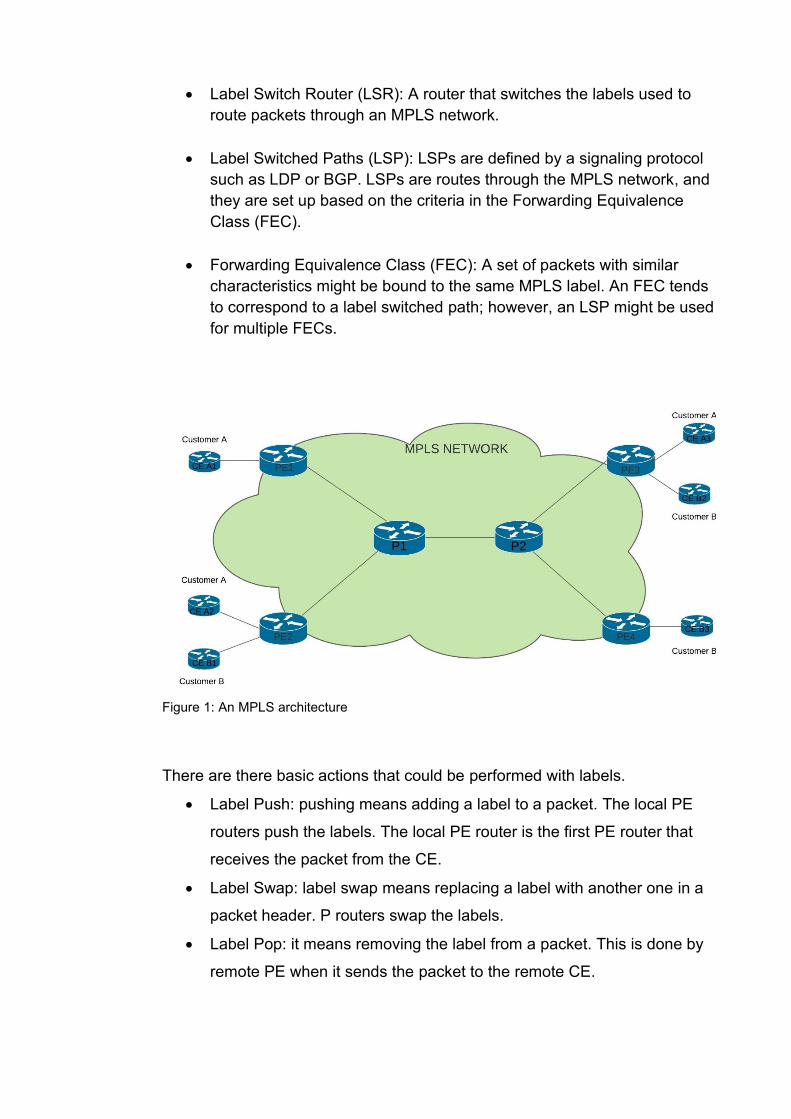
Figure 1: An MPLS architecture
There are there basic actions that could be performed with labels.
• Label Push: pushing means adding a label to a packet. The local PE
routers push the labels. The local PE router is the first PE router that
receives the packet from the CE.
• Label Swap: label swap means replacing a label with another one in a
packet header. P routers swap the labels.
• Label Pop: it means removing the label from a packet. This is done by
remote PE when it sends the packet to the remote CE.
7 MPLS-BASED VPN
Virtual Private Networks (VPNs) are private networks that use virtual tunneled
connections routed through public networks. Typically the public network
could be service provider network. VPNs provide connectivity between sepa-
rate customer sites through virtual connections (Juniper, 2019.)
Why is the solution called a Virtual Private Network? First, it is a network be-
cause it provides connectivity between separate sites. Second, it is private be-
cause the customer requires it to have the same properties and guaranties as
a private network, both in terms of network operations (addressing space,
routing) and traffic forwarding. Third, it is virtual because the same physical re-
sources and facilities could be used to provide the service to more than one
customer (Minei & Lucek, 201, 2011)
VPNs can be categorized in different ways. The categorization is based on the
way the routing information is exchanged in the VPN. According to Guichard &
Pepelnjak, VPNs can be classified into two major categories:
• Overlay VPNs: In this model, the service provider provides only Virtual
Circuits (VCs) for the customers, and routing information is exchanged
directly between the customer edge (CE) devices. A VC acts as a ded-
icated physical link between customers’ sites. If the VC is permanent,
then it is called a Permanent Virtual Circuit (PVC). If the VC is estab-
lished only as a temporary signaling protocol, it is called Switched Vir-
tual Circuit (SVC). Examples of overlay VPNs are GRE and IPSec
VPNs.
• Peer-to-peer VPNs: In this model, the routing information is exchanged
between the customers and the service provider. Example: MPLS VPN
Both models have their benefits and back-draws. Although MPLS VPN is a
peer-to-peer model, it is a combination of both models. MPLS VPN brings to-
gether the benefits of an overlay VPN such as security and isolation among
the customer, using a peer-to-peer model such as simplicity.
According to Juniper, three primary types of MPLS VPNs: Layer 2 VPNs,
Layer 2 circuits, and Layer 3 VPNs. In all kinds of MPLS VPNs, PE routers are
responsible for performing VPN functions. P and CE router does not need to
participate in performing VPN functions.
8 NOKIA TERMINOLOGY
Because different network vendors such as Cisco and Nokia use vendor-spe-
cific devices, operating systems, terms, and configurations, which are different
from others, this study tried to cover at least two major network vendors’ solu-
tions widely used in service provider networks. These two are Nokia (formerly
Alcatel-Lucent) and Cisco. The MPLS VPN concepts are the same in both
vendors’ solutions, but there are some differences in techniques and terminol-
ogies. Here, the concepts of MPLS L2 and L3 VPNs in the Nokia environment
will be examined, and after that, some examples and configurations of both
vendors will be provided.
8.1 Services
In the Nokia entities, a service is an entity identified by a service ID, but it can
only have an optional service name. A service could refer to as a type of con-
nectivity for the Internet or VPN services. A service could provide Layer 2 or
Layer 3 connectivity between service access points (SAP) within the same
router or between different routers. The SAP definition will be examined in the
next sections, but briefly, it can be described as a logical place where traffic
enters and exits the service. To understand the concepts better, let’s see this
figure:
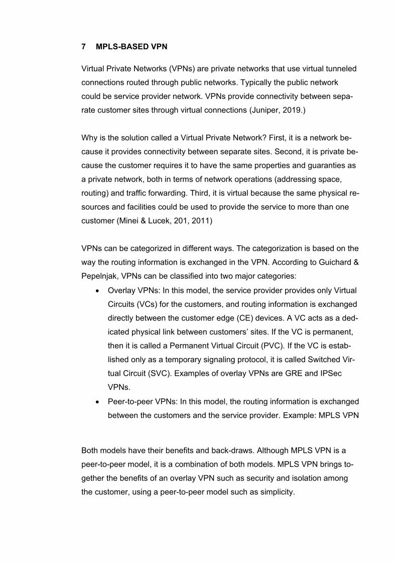
Figure 2: Nokia service tunnels
The MPLS Transport Tunnels are established between PE routers. Inside the
Transport Tunnels, there could be multiple Service Tunnels. The Service Tun-
nels carry the customer traffics. For Layer 2 MPLS VPN (VPLS & VPWS), the
Targeted LDP (TLDP) is used for establishing the Service Tunnels, but for
Layer 3 MPLS VPN (VPRN), the Multiprotocol-BGP (MP-BGP) is used to es-
tablish the tunnel.
Here are the most typical Nokia services:
• Virtual Private LAN Service (VPLS)
• Virtual Private Wire Service (VPWS), also known as Virtual Leased
Line (VLL)
• Ethernet Virtual Private Network (EVPN)
• Pseudowire (PW) Ports
• Virtual Private Routed Network (VPRN)
• Internet Enhanced Service (IES)
VPLS, VPWS, EVPN, and PW Ports are MPLS-based Layer 2 VPN services
of Nokia, and VPRN and IES are Layer 3 services. VPLS, VPWS, PW Ports,
and VPRN will be discussed in the next chapters, but other services are be-
yond this study’s scope.

8.2 Service Entities
In Nokia, logical service entities are used for service provisioning to provide
end-to-end connectivity for customer sites. It is possible to bind several ser-
vices to a single customer or a to a single LSP tunnel. Different policies such
as Quality of Service (QoS) and filtering policies can be applied to a service.
According to Nokia, a basic service configuration must have the following
items configures:
• a customer ID
• a service type
• a service ID
• an SAP for determining the encapsulation type and port
• an interface for assigning IP-addresses
• an associated SDP (for distributed services)
8.3 Customers
Customer is a primary service entity that is defined with a value named Cus-
tomer ID. When creating a service, a customer ID must be bound with the ser-
vice.
8.4 Service Access Points (SAP)
According to the Nokia definition, a Service Access Point (SAP) could be
simply considered as a logical endpoint in service for entering and exiting traf-
fic. The entering point is called ingress and exiting point egress. An SAP can
be a physical port or a channel, but it also could be a logical entity within a
physical port or channel. Depending on encapsulation types within a physical
port or channel port, there could be multiple SAPs. If a port or channel is
down, all SAPs within that port or channel would also be down.
SAPs can be configured on customer-facing ports (access ports) but not on
core-facing ports. An SAP is associated with the service in which it is created,
and it can provide access to different services such as VPLS, VPWS, and
VPRN. All SAPs in a device must be created, and there are no default SAPs
in Nokia devices.
8.4.1 SAP encapsulation types
The SAP encapsulation type is used to identify the protocol used to provide
the service (Nokia, 2017.)
For Ethernet ports, there are three types of encapsulations available.
• Null: Null encapsulation means that there is only a single service for a
single customer available on the port.
• Dot1q (IEEE 802.1Q): Dot1q is a standard protocol in networking that
supports VLANs. Dot1q encapsulation is configurable on Ethernet and
EtherChannel ports. If a port or port-channel is configured with Dot1q
encapsulation type, then it can support multiple services for one or mul-
tiple customers. The encapsulation ID of the service would be the
VLAN ID in the Dot1q header.
• Q-in-Q (VLAN stacking): Q-in-Q encapsulation is a technique that adds
a second VLAN tag to customers’ frames. The service provider uses a
unique VLAN tag (outer tag) for each customer, but the customers
could still use their inner tag. Using this technique, we can separate
each customer’s traffic from others and have multiple VLANs. Q-in-Q is
supported on VPWS, VPLS, VPRN, and IES.
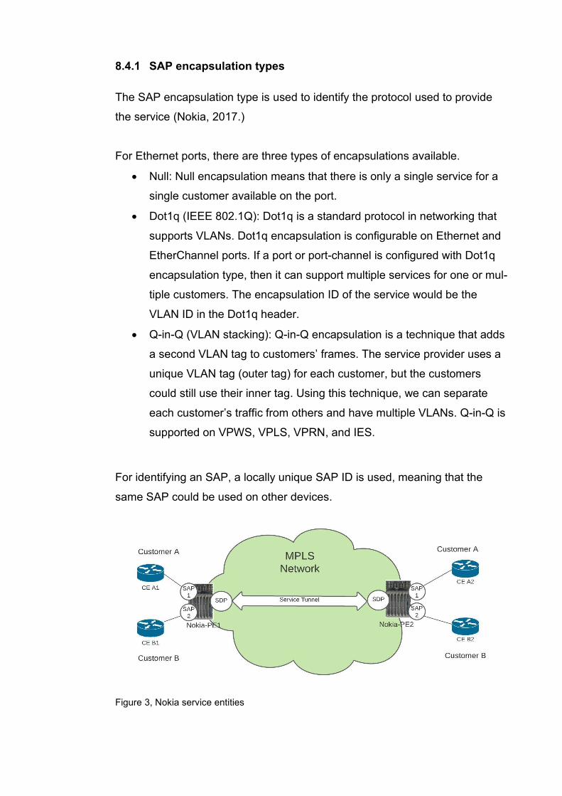
For identifying an SAP, a locally unique SAP ID is used, meaning that the
same SAP could be used on other devices.
Figure 3, Nokia service entities
8.5 Service Distribution Points (SDP)
According to Nokia, SAPs are linked to the transport tunnels using a Service
Distribution Point (SDP). An SDP is created to identify the endpoint of a ser-
vice tunnel. After creating an SDP, it could be bind to service to create a ser-
vice tunnel called a transport tunnel. The transport tunnel is a logical Label-
Switched Path (LSP), which uses a signaling protocol like Label Distribution
Protocol (LDP) or Resource Reservation Protocol-Traffic Engineering (RSVP-
TE) for signaling. SDP uses the far-end device’s IP address to build the tunnel
path. All tunnels are unidirectional, so if the far-end device needs to send traf-
fic back to the local device, it needs to create a new tunnel.
A Distributed service is a service that is bound to an SDP. In a distributed ser-
vice configuration, there are at least two SAPs (one in local node and one in
remote node). An SDP could be used for binding the service to a service tun-
nel.
Because an SDP ID is locally unique, the same ID could also be used on
other devices. An SDP can be associated with one or multiple services. Each
SDP service tunnel has an ingress and egress point for the Pseudowires (PW)
contained with it. We will go through Pseudowires in the next sections.
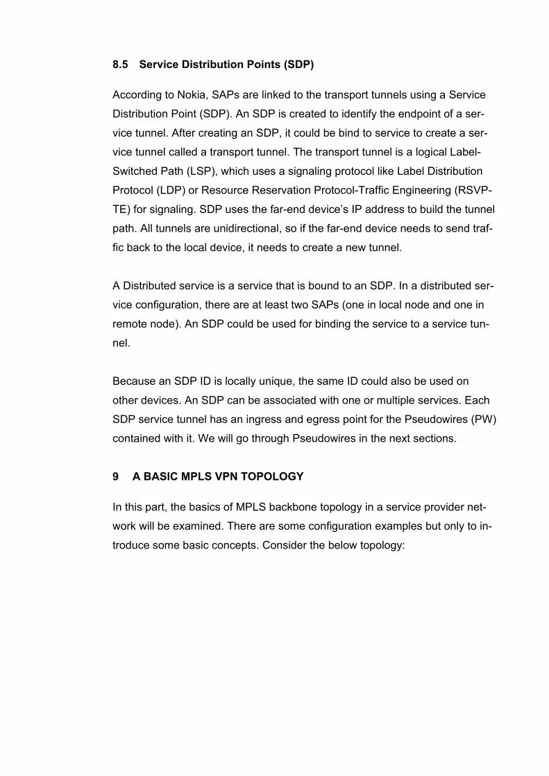
9 A BASIC MPLS VPN TOPOLOGY
In this part, the basics of MPLS backbone topology in a service provider net-
work will be examined. There are some configuration examples but only to in-
troduce some basic concepts. Consider the below topology:
9.1.1 Step 1: Creating IGP
This step is beyond the scope of this study, but here it is discussed briefly. Be-
fore anything else, an Interior Gateway Protocol (IGP) is enabled between
backbone routers. An IGP is used for exchanging the routing information be-
tween routers within an autonomous system (AS). Intermediate system to in-
termediate system (IS-IS) and Open Shortest Path First (OSPF) are the typi-
cal IGP protocols among the service provider backbones.
In Nokia routers, the IGP can be checked by these commands:
❖ If IS-IS is enabled as IGP: ▪ Show router isis adjacency ▪ Show router isis database ▪ Show router isis topology ▪ Show router isis routes
❖ If OSPF is enabled as IGP: ▪ Show router ospf neighbor ▪ Show router ospf database ▪ Show router ospf status ▪ Show router ospf routes
9.2 Configuring iBGP for PE-to-PE connectivity
Service providers use internal BGP protocol for creating connectivity between
PE routers in an MPLS-based backbone network. PE routers form an iBGP
session that is used for many purposes. BGP could be used as a signaling
protocol for L2 and L3 VPNs. The iBGP session is formed between routers be-
long to the same Autonomous System (AS). In MPLS VPN, PE routers ex-
change the VPNv4 routes via Multiprotocol BGP (MP-BGP). The concepts will
be discussed in the next chapters. The configuration of iBGP between PE
routers is beyond the scope of this study.
9.3 Step 2: Configuring MPLS and Enabling Label Distribution Protocol
(LDP) Or Resource Reservation Protocol (RSVP)
Label Distribution Protocol (LDP) is a protocol used to distribute labels in non-
traffic-engineered applications. LDP allows routers to establish label switched
paths (LSPs) through a network by mapping network-layer routing information
directly to data-link layer switched paths. LDP performs the label distribution
only in MPLS environments. LDP operation is performed between LDP peers.
LDP peers are two Label Switch Routers (LSRs). When an LDP session is
created between two LSRs, they begin to learn each other’s label mappings
and exchange label binding information (Nokia, 2017.)
According to Juniper, there three types of LSPs: Static LSPs, LDP-signaled
LSPs, and RSVP-signaled LSPs. For static LSPs, no signaling protocol is
needed, and labels are manually assigned to all participating routers. LDP-sig-
naled LSPs are created dynamically using LDP.
Resource Reservation Protocol (RSVP) is another protocol used to distribute
labels, especially in traffic-engineered applications. RSVP is a more compli-
cated protocol than LDP and has features like allowing explicit path and band-
width reservation for the LSPs. RSVP must be enabled on the router inter-
faces that participate in signaled LSPs.
There two kinds of RSVP-signaled LSPs:
• Explicit-path LSPs: in this type, all intermediate hops (strict, loose, or a
combination of the two) of the LSP are created manually.
• Constrained-path LSPs: in this type, the intermediate hops of the LSPs
are automatically created. The needed information is provided by the
link-state routing protocols like IS-IS or OSPF.
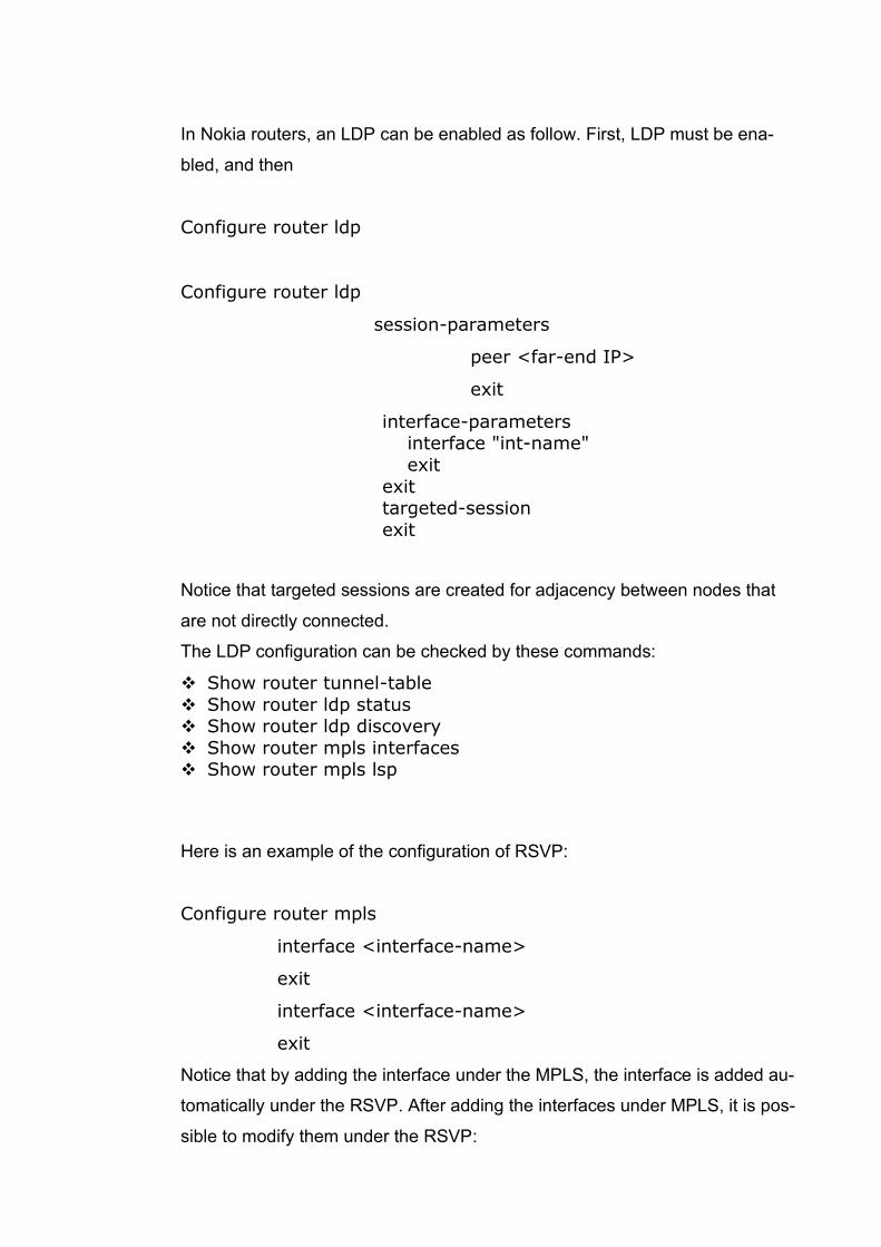
In Nokia routers, an LDP can be enabled as follow. First, LDP must be ena-
bled, and then
Configure router ldp
Configure router ldp
session-parameters
peer <far-end IP>
exit
interface-parameters interface "int-name"
exit
exit targeted-session
exit
Notice that targeted sessions are created for adjacency between nodes that
are not directly connected.
The LDP configuration can be checked by these commands:
❖ Show router tunnel-table
❖ Show router ldp status ❖ Show router ldp discovery
❖ Show router mpls interfaces ❖ Show router mpls lsp
Here is an example of the configuration of RSVP:
Configure router mpls
interface <interface-name>
exit
interface <interface-name>
exit
Notice that by adding the interface under the MPLS, the interface is added au-
tomatically under the RSVP. After adding the interfaces under MPLS, it is pos-
sible to modify them under the RSVP:
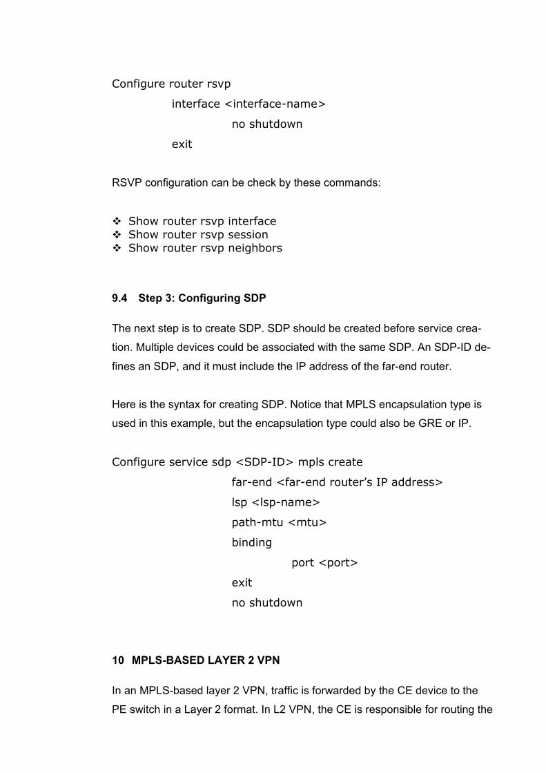
Configure router rsvp
interface <interface-name>
no shutdown
exit
RSVP configuration can be check by these commands:
❖ Show router rsvp interface
❖ Show router rsvp session ❖ Show router rsvp neighbors
9.4 Step 3: Configuring SDP
The next step is to create SDP. SDP should be created before service crea-
tion. Multiple devices could be associated with the same SDP. An SDP-ID de-
fines an SDP, and it must include the IP address of the far-end router.
Here is the syntax for creating SDP. Notice that MPLS encapsulation type is
used in this example, but the encapsulation type could also be GRE or IP.
Configure service sdp <SDP-ID> mpls create
far-end <far-end router’s IP address>
lsp <lsp-name>
path-mtu <mtu>
binding
port <port>
exit
no shutdown
10 MPLS-BASED LAYER 2 VPN
In an MPLS-based layer 2 VPN, traffic is forwarded by the CE device to the
PE switch in a Layer 2 format. In L2 VPN, the CE is responsible for routing the
traffic, and the service provider only carries the traffic from the customer’s one
site to another using the MPLS backbone. From a customer’s view, the topol-
ogy is like connecting their different sites to different ports of a switch, and
they seem to be in the same LAN.
In Nokia services, there are different types of MPLS-based Layer 2 VPNs, but
in this study, these are discussed:
• Ethernet Virtual Private Network (EVPN)
• Virtual Private LAN Service (VPLS)
• Virtual Private Wire Service (VPWS), also know as Virtual Leased Line
(VLL)
10.1 Virtual Private LAN Service (VPLS)
According to Nokia, Virtual Private LAN Service (VPLS) is a Layer 2 MPLS-
based VPN multipoint-to-multipoint technology. This technology connects geo-
graphically separated customer LANs over an MPLS network. Multiple sites
connected through a VPLS seem to be connected to different Layer 2 ports
and seem to be in the same LAN. The VPLS requires creating a bridge do-
main and Virtual Forwarding Instance on each PE router in Cisco IOS XR. In
the next section, some basic concepts are about VPLS will be explained.
10.1.1 Bridge Domain
VPLS uses a bridge domain to provide Layer 2 connectivity between different
sites through a broadcast domain. A broadcast domain consists of virtual or
physical ports. Within a bridge domain, data frames are switched based on
their destination MAC addresses.
10.1.2 Virtual Forwarding Instance (VFI)
The VFI is one of the basic concepts of the VPLS. A VFI could be created on
a PE router for each VPLS instance. Native bridging functions such as learn-
ing and forwarding MAC addresses could be performed by a VFI. After creat-
ing the VFI in a PE router, the PE router can establish Virtual Circuits to all
other PE routers in that VPLS instance. A Virtual Switch Instance (VSI) will be
created by connecting a bridge domain to a VFI (Cisco 2018.)
10.1.3 Pseudowires (PW)
VPLS services can be connected using pseudowires (PWs). PWs are used to
establish a tunnel between two PE routers to transport Layer 2 protocol data
units (PDU) across an MPLS network. PWs are established dynamically or
statically, and they could be configured either as a mesh or a spoke SDP. In
the next chapter, mesh and spoke SDP would be discussed.
10.2 Typical VPLS Network topologies
There are three basic types of VPLS topology, according to the Service Distri-
bution Points (SDP) types:
• Hub and Spoke VPLS: In this topology, the devices are connected us-
ing a spoke SDP. This type of SDP is like a bridged port, in which the
received traffic is forwarded to all other ports. The spoke SDP forwards
the received traffic to all connected spoke SDPs, mesh SDPs, and
SAPs.
• Full-Mesh VPLS: In a full-mesh VPLS topology, devices (PE routers)
are connected using mesh SDP type. A mesh SDP is a type of SDP
that forwards the received traffic to all connected spoke SDPs and
SAPs, but mesh SDP doesn’t forward the traffic to other connected
mesh SDPs. This is also called a split-horizon rule. In Cisco IOS XR,
Virtual Forwarding Instances (VFIs) and Pseudowires (PW) are used to
implement the split-horizon rule.
• Hierarchical VPLS (H-VPLS): This is an enhancement of VPLS that
consists of both spoke SDPs and mesh SDPs. Let’s see this one in
more detail in the next section.
In mesh and spoke SDP, VLAN tags could be added to the frames for trans-
mitting data, and VLAN tags could be removed when receiving data. There
are three types of VLAN tags: zero, one, and two. These could be considerd
as the corresponding of the null, dot1q, and QinQ in SAP operations.
10.2.1 Hierarchical VPLS
In a hierarchical VPLS (H-VPLS), some drawbacks of non-hierarchical topolo-
gies are eliminated. There are some drawbacks in non-hierarchical VPLS to-
pologies where CE devices are directly connected to the PE devices. In these
topologies, the PE devices are responsible for many tasks like holding the
routing and forwarding tables. This is not optimal, and these heavy tasks can
cause a significant load on the device and could affect the functionality.
In a hierarchical VPLS, these problems are solved by adding additional nodes.
These nodes are called the user face of Provider Edge (u-PE), also known as
Access PE. The customer traffic is routed through these Access PE toward
the service provider core. The Access PE device could be an Ethernet switch,
and it is the first node that receives the customer traffic, but it doesn’t need to
know the whole routing table.
The Access PE device transfer traffics toward the network face of Provider
Edge or n-PE devices. A pseudowire (PW) is used to connect between u-PE
and n-PE. The encapsulation type is Q-in-Q tagging. There are more details
about pseudowires (PW) and Q-in-Q tagging in this study.
Hierarchical VPLS has many benefits over non-hierarchical VPLS, such as
scalability, efficient bandwidth usage, and simple management. The hierar-
chical VPLS architecture is more complicated than non-hierarchical, and this
could be one of the disadvantages of hierarchical VPLS.
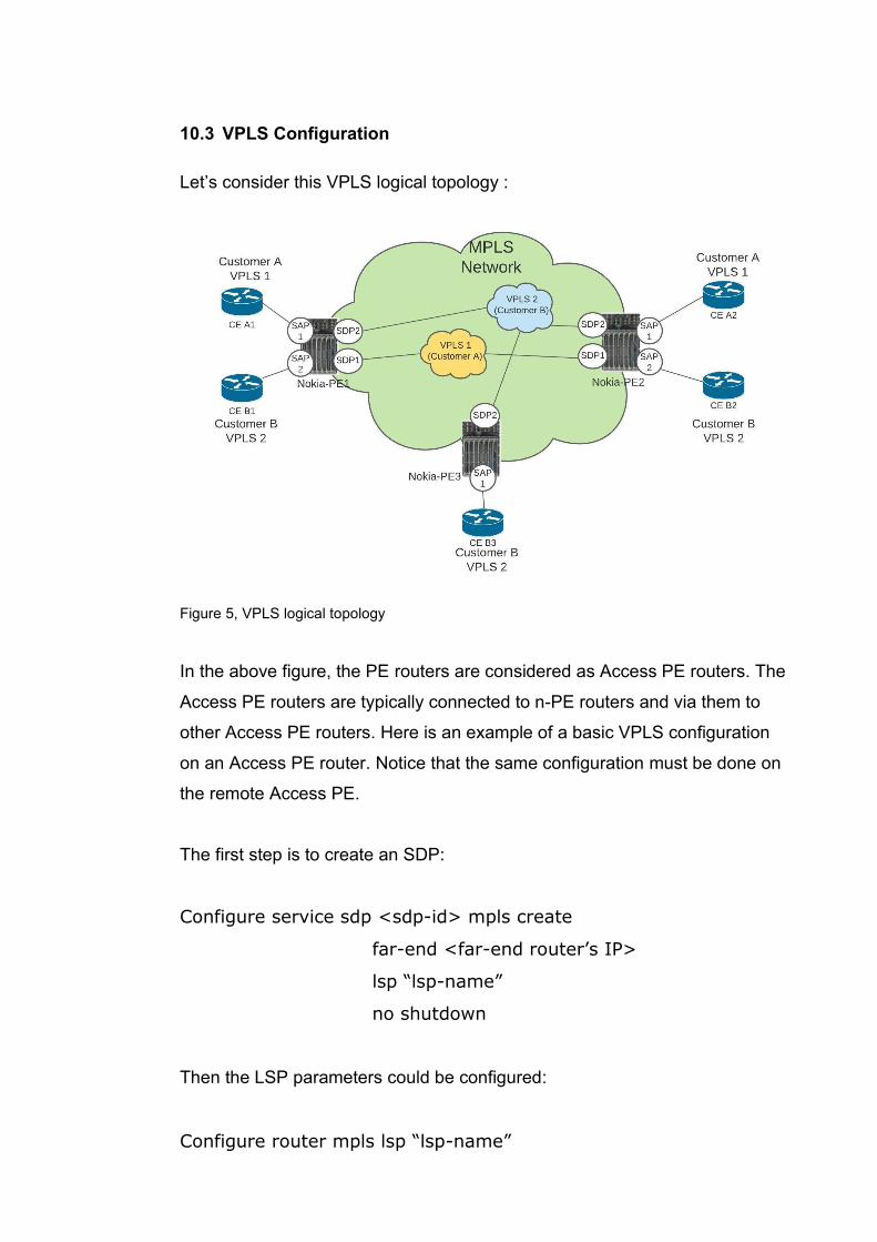
10.3 VPLS Configuration
Let’s consider this VPLS logical topology :
Figure 5, VPLS logical topology
In the above figure, the PE routers are considered as Access PE routers. The
Access PE routers are typically connected to n-PE routers and via them to
other Access PE routers. Here is an example of a basic VPLS configuration
on an Access PE router. Notice that the same configuration must be done on
the remote Access PE.
The first step is to create an SDP:
Configure service sdp <sdp-id> mpls create
far-end <far-end router’s IP>
lsp “lsp-name”
no shutdown
Then the LSP parameters could be configured:
Configure router mpls lsp “lsp-name”
to “n-PE-IP”
cspf
primary “IGP”
no shutdown
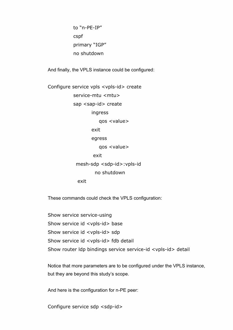
And finally, the VPLS instance could be configured:
Configure service vpls <vpls-id> create
service-mtu <mtu>
sap <sap-id> create
ingress
qos <value>
exit
egress
qos <value>
exit
mesh-sdp <sdp-id>:vpls-id
no shutdown
exit
These commands could check the VPLS configuration:
Show service service-using
Show service id <vpls-id> base
Show service id <vpls-id> sdp
Show service id <vpls-id> fdb detail
Show router ldp bindings service service-id <vpls-id> detail
Notice that more parameters are to be configured under the VPLS instance,
but they are beyond this study’s scope.
And here is the configuration for n-PE peer:
Configure service sdp <sdp-id>
far-end <IP>
lsp “lsp-name”
primary “IGP”
no shutdown
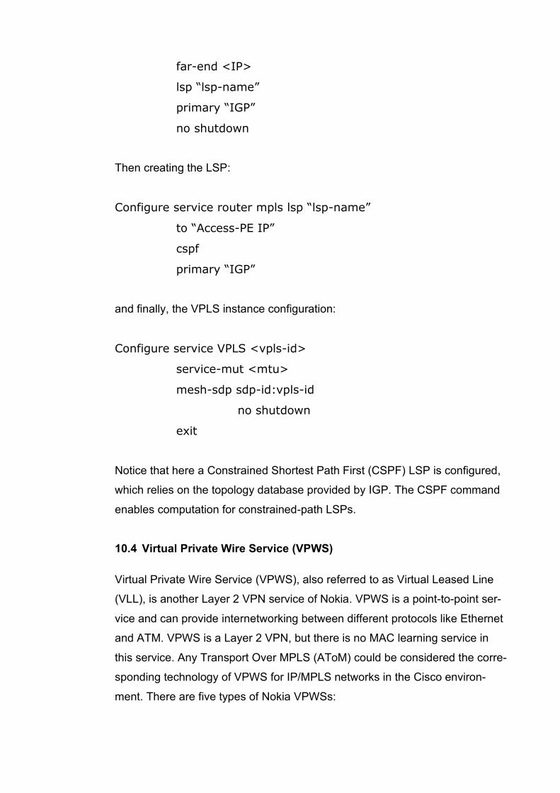
Then creating the LSP:
Configure service router mpls lsp “lsp-name”
to “Access-PE IP”
cspf
primary “IGP”
and finally, the VPLS instance configuration:
Configure service VPLS <vpls-id>
service-mut <mtu>
mesh-sdp sdp-id:vpls-id
no shutdown
exit
Notice that here a Constrained Shortest Path First (CSPF) LSP is configured,
which relies on the topology database provided by IGP. The CSPF command
enables computation for constrained-path LSPs.
10.4 Virtual Private Wire Service (VPWS)
Virtual Private Wire Service (VPWS), also referred to as Virtual Leased Line
(VLL), is another Layer 2 VPN service of Nokia. VPWS is a point-to-point ser-
vice and can provide internetworking between different protocols like Ethernet
and ATM. VPWS is a Layer 2 VPN, but there is no MAC learning service in
this service. Any Transport Over MPLS (AToM) could be considered the corre-
sponding technology of VPWS for IP/MPLS networks in the Cisco environ-
ment. There are five types of Nokia VPWSs:
• Pipe: Epipe is a point-to-point Layer 2 service of Nokia. Epipe is one of
the widely used WPWS services in service provider networks because
Ethernet is a widely used technology. An Epipe service can use SAPs
and SDPs to build a tunnel to transfer customer data between different
Ethernet protocol sites. Like other VPWS types, Epipe doesn’t use
MAC learning.
• Ipipe: Internetworking pipe is a VPWS VPN service between two nodes
that use different technologies.
• Apipe: Asynchronous Transfer Mode (ATM) pipe is a service between
two ATM SAPs.
• Fpipe: Frame-Relay pipe is VPWS VPN service between two Frame-
Relay sites.
• Cpipe: Cpipe is a VPWS VPN service between two nodes that use
Time Division Multiplexing (TDM) technology
In Epipe, it is possible to use encapsulations with SAPs. These encapsula-
tions are Null, Dot1q, and Q-in-Q. (explain with details)
10.5 Creating an Epipe
In service provider networks, Epipe could provide a Layer 2 connectivity be-
tween aggregation nodes (AGN) and service termination points (ABR). The
AGN could be considered as Access PE and the ABR as n-PE.
Let’s consider a simple topology for configuring an Epipe:
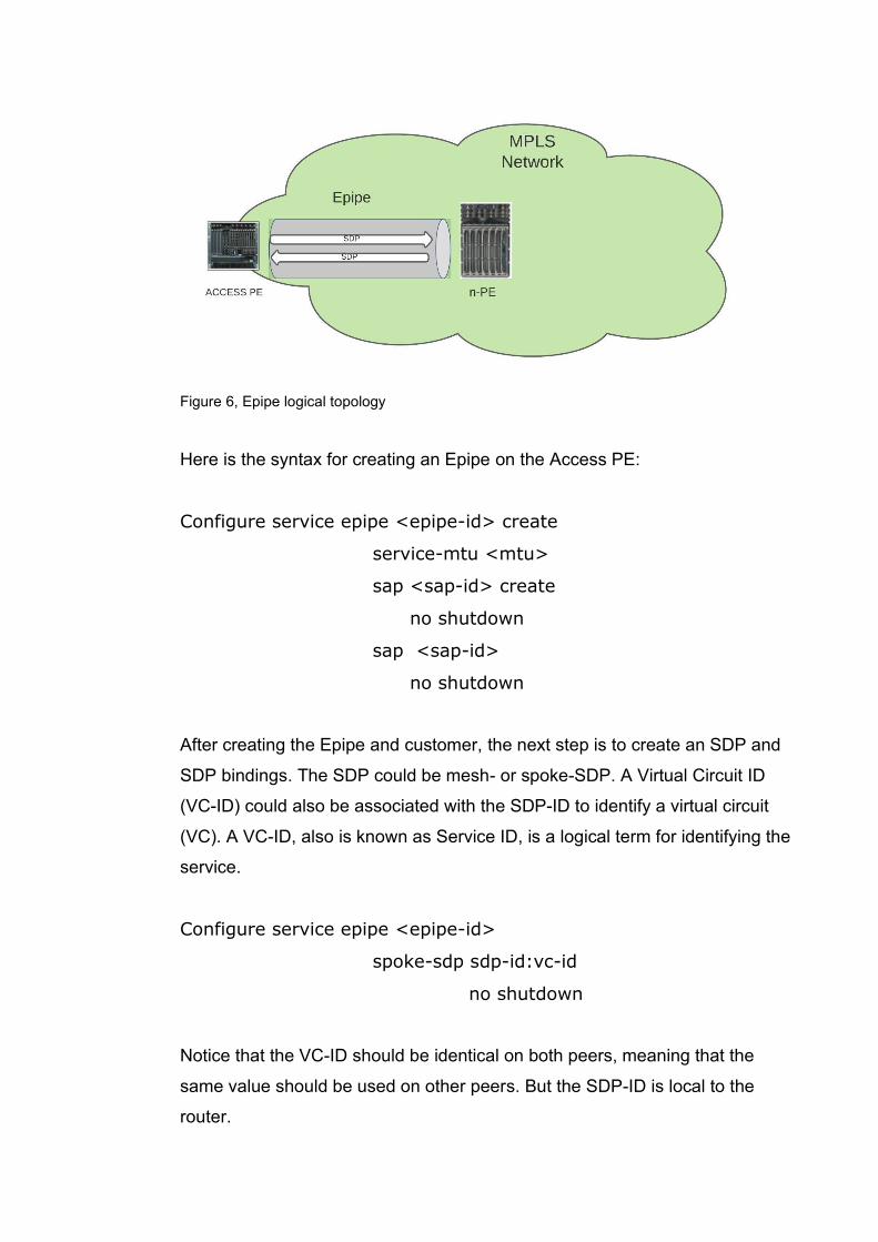
Figure 6, Epipe logical topology
Here is the syntax for creating an Epipe on the Access PE:
Configure service epipe <epipe-id> create
service-mtu <mtu>
sap <sap-id> create
no shutdown
sap <sap-id>
no shutdown
After creating the Epipe and customer, the next step is to create an SDP and
SDP bindings. The SDP could be mesh- or spoke-SDP. A Virtual Circuit ID
(VC-ID) could also be associated with the SDP-ID to identify a virtual circuit
(VC). A VC-ID, also is known as Service ID, is a logical term for identifying the
service.
Configure service epipe <epipe-id>
spoke-sdp sdp-id:vc-id
no shutdown
Notice that the VC-ID should be identical on both peers, meaning that the
same value should be used on other peers. But the SDP-ID is local to the
router.
These commands can be used to verify the configuration:
Show service id <vc-id> base
Show service id <vc-ic> sdp <sdp-id> detail
Show service sap-using sap <sap-id>
Show service sdp <sdp-id> detail
10.6 Ethernet Virtual Private Network (EVPN)
In this part, the EVPN will be discussed briefly. Due to the limitation of the
study, we will not go through the details and configuration here.
An Ethernet VPN (EVPN) introduces a new Layer 2 VPN technology that can
connect remote customer sites using a Layer 2 virtual bridge. According to
Nokia, EVPN is a BGP MPLS-Based Ethernet VPN created for allowing VPLS
service to be operated as IP-VPNs. EVPN has many benefits like multi-hom-
ing capabilities, simple provision, and management. The main objective of
EVPN is to support MAC learning within the control plane and active-active
multi-homing by creating an E-VLAN service similar to IP-VPNs. EVPN can
enable integrated Layer 2 and Layer 3 services over Ethernet with multi-hom-
ing.
An E-LAN is a multipoint-to-multipoint service that connects multiple User Net-
work Interfaces (UNI) for customers and can provide connectivity between
customer sites. E-LANs are used to create multipoint L2 VPNs, transparent
LAN services, and Layer 2 VPNs.
Like other types of VPNs discussed in this study, EVPN also consists of CE
devices connected to PE devices. In EVPN, the data plane and control plane
are separated. EVPN can be used as the control plane for different data plane
encapsulations. EVPN-VXLAN, EVPN-MPLS, and PBB-EVPN are three types
of EVPN. EVPN-VXLAN has mainly been used in data center EVPN applica-
tions. In EVPN-MPLS, the MPLS network is used by EVPN for creating E-LAN
services. Generally, EVPN-MPLS is an evolution of VPLS services in the
WAN. The EVPN for Provider Backbone Bridging (PBB-EVPN) is a simplified
EVPN that does not have the advanced features of EVPN-MPLS, but it pro-
vides very high scalability for networks. Further explanation of these technolo-
gies is beyond the scope of this study.
10.7 Pseudowire Ports (PW ports)
In this part, the Pseudowire ports concept will be discussed briefly because
the details of this topic are beyond this study’s scope.
According to Nokia, a PW port represents an extraction of payload carried
within a tunnel. This payload is extracted onto a PW SAP within a service con-
text (such as an Epipe, VPRN, or IES). A PW port can have a fixed connection
to a physical port or switch between ports. If the PW port switches between
ports, then it is called a Flex PW port.
Each port eligible to transmit traffic on a Flex PW port must be added to a PW-
port-list. An MPLS-based spoke SDP can be rerouted between the ports de-
fined in the PW port list and still be mapped to the same PW port based on the
service label. Here is the instruction for provisioning an MPLS-based spoke
SDP on a Flex PW port:
1. Creating a PW-port-list and adding ports to that:
configure service system pw-port-list
Port <port>
2. Creating PW port:
configure pw-port <id> create
3. Configuring tunnel:
configure sdp <id> mpls create
far-end <IP>
exit
4. Terminating the tunnel on a PW port via an Epipe service.
configure epipe <id> create
pw-port <id>
spoke-sdp <sdp-id>:vc-id
11 MPLS LAYER 3 VPN
Layer 3 of the OSI model is the network layer. A VPN that operates in layer 3
through an MPLS network is called MPLS layer 3 VPN. In the MPLS Layer 3
VPN, the customer traffic is routed by the service provider routers. The service
provider learns the IP addresses of CE devices and customer routes and has
a wider VPN routing and forwarding (VRF) policy configuration than the Layer
2 VPN.
11.1 Virtual Routing and Forwarding (VRF)
By default, a router uses a single global routing table that contains all the di-
rectly connected networks and prefixes that it learned through static or dy-
namic routing protocols. Virtual Routing and Forwarding (VRF) is a technique
that creates multiple virtual networks within a network entity.
In MPLS VPN architecture, VRFs are like VLAN for routers. Instead of using a
single global routing, it is possible to use multiple virtual routing tables. Each
VPN could have its routing and forwarding table in the router. In other words,
PE routers could build a separate routing and forwarding table for each VPN
(customer). This feature also allows overlapping IP-addresses between differ-
ent VPNs as long as those VPNs do not have connectivity. For example, the
same network address, 172.16.1.0/24, could be used by more than one VPN
within a router.
A Route Distinguisher (RD) value is added to the prefixes for separating the
prefixes between the VPNs. For example, consider that there are two different
VPNs (customers) on a PE router. Both use the 172.16.1.0/24 network for
their sites. An 8-byte field could be added to the beginning of the prefix to dis-
tinguish the routes between two VPNs. For example, 77:10 can be used for
one VPN and 88:10 for another VPN. This 8-byte field could be any number,
but typically service providers use some logic to define an RD. The combina-
tion of RD and prefix is called a VPNv4 route.
Another important concept related to VRFs is Route Target (RT). The RT is
used to determine the import and export of routes within each VRF. Route
Target could be configured as Export Route Target policy and Import Route
Target policy to determine the export and import policies for each VRF. It is
also possible to decide on both policies under one comment if the export and
import policies are the same.
The Route Target is a useful tool for manipulating VPNv4 routes between the
VPNs. RT is an 8-bytes BGP extended community value. BGP extended com-
munity is used to carry additional information with BGP. BGP extended com-
munity also carries another value named route origin, which prevents routing
loops by identifying which site originated the route and therefore not advertis-
ing the route back to the originating site.
The PE routers peer with locally connected CE, but CE routers do not need to
peer among themselves because routing information is exchanged via PE
routers. Because RD allows overlapping of IP-address between different cus-
tomers (VPRNs), at the destination PE router, the correct VPRN is identified
by the Route Target (RT).
11.2 Virtual Private Routed Networks (VPRN)
VPRN is an MPLS-based Layer 3 VPN. In VPRN PE routers exchange cus-
tomer routing information via Multiprotocol BGP (MP-BGP). VPRN association
for each route is identified by route distinguisher (RD). RD is included in MP-
BGP. After adding an RD to the prefix, a VPNv4 address is created, and it will
be globally unique. The figure below shows a logical VPRN topology:
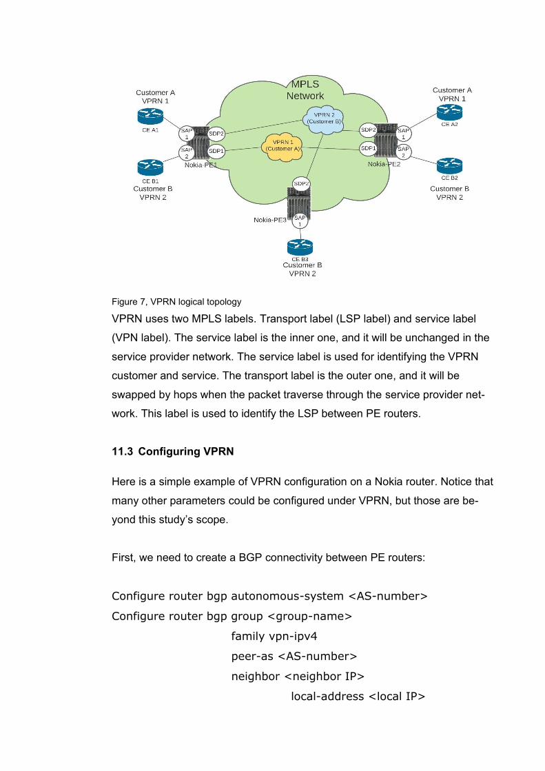
Figure 7, VPRN logical topology
VPRN uses two MPLS labels. Transport label (LSP label) and service label
(VPN label). The service label is the inner one, and it will be unchanged in the
service provider network. The service label is used for identifying the VPRN
customer and service. The transport label is the outer one, and it will be
swapped by hops when the packet traverse through the service provider net-
work. This label is used to identify the LSP between PE routers.
11.3 Configuring VPRN
Here is a simple example of VPRN configuration on a Nokia router. Notice that
many other parameters could be configured under VPRN, but those are be-
yond this study’s scope.
First, we need to create a BGP connectivity between PE routers:
Configure router bgp autonomous-system <AS-number>
Configure router bgp group <group-name>
family vpn-ipv4
peer-as <AS-number>
neighbor <neighbor IP>
local-address <local IP>
The same configuration must also be done on other peers.
The second step is to configure VPRN parameters and bound them with cor-
responding interfaces.
Configure service vprn <vprn-id> create
vrf-import “vrf-import policy”
vrf-export “vrf-export policy”
autonomous-system <BGP-AS-number>
route-distinguisher <RD-id>
type <spoke or hub>
auto-bind-tunnel
resolution-filter
ldp
rsvp
exit
In the above configuration example, the VRF import and export policies are
created for the VPRN to determine how routes are exported from the local
VRF to other VRFs and how routes are imported from other VRFs to the local
VRF. The is done using the BGP extended community.
The BGP autonomous system (AS) of the service provider is configured. The
type of VPRN is configured as spoke or hub, and the auto-bind-tunnel resolu-
tion-filter command configures the automatic binding of a VPRN service using
tunnels to MP-BGP. Notice that LDP and RSVP tunnel types were configured
here, but other tunnel types such as GRE also could be configured.
Now the interfaces could be configured:
Configure service vprn <vprn-id>
interface <int-name>
address <IP>
exit
ip-mtu <mtu>
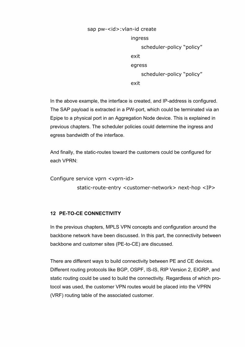
sap pw-<id>:vlan-id create
ingress
scheduler-policy “policy”
exit
egress
scheduler-policy “policy”
exit
In the above example, the interface is created, and IP-address is configured.
The SAP payload is extracted in a PW-port, which could be terminated via an
Epipe to a physical port in an Aggregation Node device. This is explained in
previous chapters. The scheduler policies could determine the ingress and
egress bandwidth of the interface.
And finally, the static-routes toward the customers could be configured for
each VPRN:
Configure service vprn <vprn-id>
static-route-entry <customer-network> next-hop <IP>
12 PE-TO-CE CONNECTIVITY
In the previous chapters, MPLS VPN concepts and configuration around the
backbone network have been discussed. In this part, the connectivity between
backbone and customer sites (PE-to-CE) are discussed.
There are different ways to build connectivity between PE and CE devices.
Different routing protocols like BGP, OSPF, IS-IS, RIP Version 2, EIGRP, and
static routing could be used to build the connectivity. Regardless of which pro-
tocol was used, the customer VPN routes would be placed into the VPRN
(VRF) routing table of the associated customer.
The routes learned from customers will be advertised through Multiprotocol
BGP (MP-BGP) to other PE routers. The advertised routes are in VPNv4 for-
mat. If the routes are learned from the CE router via other protocols than BGP,
then the routes must be redistributed into the MP-BGP. If the routes are
learned via BGP from the CE router, then the redistribution is done automati-
cally. Notice that this protocol used for CE-to-PE connectivity is external BGP
(eBGP), but the protocol used for connectivity between PE routers is internal
BGP (iBGP).
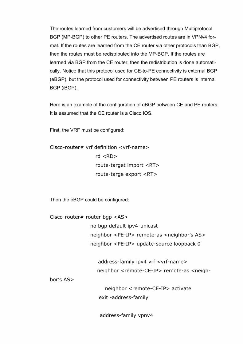
Here is an example of the configuration of eBGP between CE and PE routers.
It is assumed that the CE router is a Cisco IOS.
First, the VRF must be configured:
Cisco-router# vrf definition <vrf-name>
rd <RD>
route-target import <RT>
route-targe export <RT>
Then the eBGP could be configured:
Cisco-router# router bgp <AS>
no bgp default ipv4-unicast
neighbor <PE-IP> remote-as <neighbor’s AS>
neighbor <PE-IP> update-source loopback 0
address-family ipv4 vrf <vrf-name>
neighbor <remote-CE-IP> remote-as <neigh-
bor’s AS>
neighbor <remote-CE-IP> activate
exit -address-family
address-family vpnv4
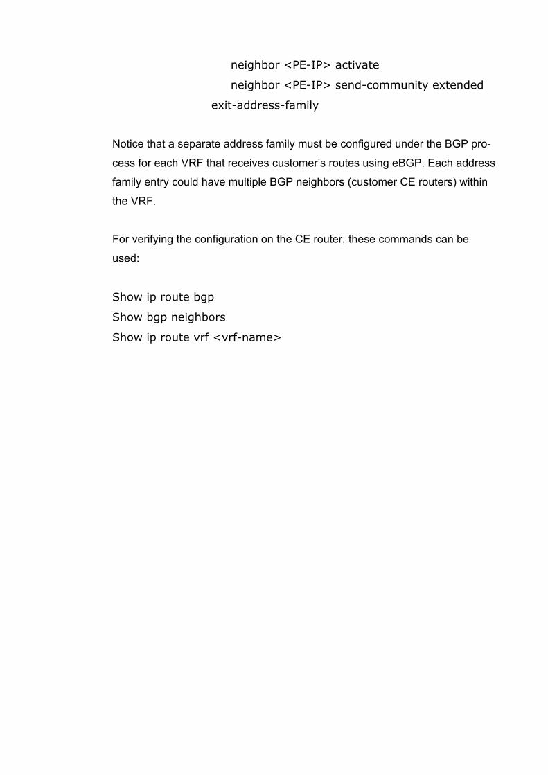
neighbor <PE-IP> activate
neighbor <PE-IP> send-community extended
exit-address-family
Notice that a separate address family must be configured under the BGP pro-
cess for each VRF that receives customer’s routes using eBGP. Each address
family entry could have multiple BGP neighbors (customer CE routers) within
the VRF.
For verifying the configuration on the CE router, these commands can be
used:
Show ip route bgp
Show bgp neighbors
Show ip route vrf <vrf-name>

13 CONCLUSION
This thesis was commissioned by the South-Eastern Finland University of Ap-
plied Sciences (XAMK). Among other courses, XAMK offers a service provider
course for ICT students, and the topic of the course is generally MPLS VPN.
This thesis’s purpose was to answer these questions:
• How to extend XAMK service provider course material to cover also Nokia MPLS VPN solutions?
• What does a junior network specialist need to know about MPLS VPN?
The goal was accomplished by studying a Finnish service provider MPLS VPN
implementation and comparing the implementation with XAMK service pro-
vider course contents. The mentioned course could use the thesis results as
an additional study source to familiarize students with the Nokia environment.
The XAMK service provider course offers a decent learning environment, in-
cluding theory, configuration guide, and virtual laboratory environment for ex-
ercising but only in the Cisco IOS environment. At the same time, Finnish ser-
vice providers widely use Nokia MPLS VPN solutions. Although most of the
MPLS VPN concepts are the same between Cisco and Nokia, technical imple-
mentations, terminologies, and configurations are very different. The results of
this study could be used as an additional source of study by the XAMK service
provider course to familiarize the students with MPLS VPN from Nokia’s point
of view. For example, Nokia configuration examples of MPLS VPN provided in
this study could be considered correspondingly to Cisco’s, which already exist
in the mentioned course.
A more significant impact could be made by starting a project to provide a vir-
tual laboratory environment for students to get their hands on configuration not
only on Cisco IOS but also on the Nokia SROS environment. Besides, the
configuration examples of this study could be tested in that virtual environ-
ment.
The results of this study could also be used as a brief guide of MPLS VPN in
the Nokia environment by everyone interested in this topic, especially junior
network specialists or network trainees who start working in service provider
environments but do not have too much knowledge about MPLS VPN.
On the whole, the study could be considered as a successful one because its
goals were accomplished. This study consists of theoretical frameworks and a
practical approach. Credible references were used for writing the theory and
also backing the findings of the practical section.
14 SOURCES
Bakker, A., & Van Eerde, D. 2013. An introduction to design-based
research with an example from statistics education. Available at:
https://www.researchgate.net/ [Referenced on 30.11.2020].
Cisco. 2018. MPLS L2VPN Pseudowire. Available at:
https://www.cisco.com/c/en/us/support/docs/multiprotocol-label-switching-
mpls/mpls/213238-mpls-l2vpn-pseudowire.html [Referenced on 30.11.2020].
Cisco. Implementing Multipoint Layer 2 Bridging Services (VPLS) on Cisco
ASR 9000 Series Routers. Available at:
https://www.cisco.com/en/US/docs/routers/asr9000/software/mpls/configura-
tion/guide/gcasr9kvpls.html [Referenced on 30.11.2020].
Juniper. 2019. MPLS VPN Overview. Available at:
https://www.juniper.net/documentation/en_US/junos/topics/concept/mpls-se-
curity-vpn-overview.html [Referenced on 30.11.2020].
Nokia. 2017. MPLS Guide. WWW-document. Available at:
https://infocenter.nokia.com/public/7750SR150R1A/in-
dex.jsp?topic=%2Forg.nokia.help.all%2Fhtml%2Findex.html [Referenced on
30.11.2020].
Minei, I. & Lucek, J. 2011. MPLS-enabled applications: emerging develop-
ments and new technologies. West Sussex, United Kingdom: John Wiley &
Sons Ltd.
Nokia. 2017. Layer 2 Services and EVPN Guide R15.0.R1. Available at:
https://infocenter.nokia.com/public/7750SR150R1A/in-
dex.jsp?topic=%2Forg.nokia.help.all%2Fhtml%2Findex.html [Referenced on
30.11.2020].
Nokia. 2017. Layer 3 Services Guide R15.0.R1. Available at:
https://infocenter.nokia.com/public/7750SR150R1A/in-
dex.jsp?topic=%2Forg.nokia.help.all%2Fhtml%2Findex.html [Referenced on
30.11.2020].
Pepelnjak, I. & Guichard, J. MPLS, and VPN architectures. Indianapolis, USA:
Cisco Press.
Related Documents