MPLS aware MPLS L2-VPN VPWS (PW) and VPLS MPLS L3-VPN unified RFC 3107 carry label information BGPv4 Core Aggregation Access design configurations example Massimiliano Sbaraglia

Welcome message from author
This document is posted to help you gain knowledge. Please leave a comment to let me know what you think about it! Share it to your friends and learn new things together.
Transcript
MPLS awareMPLS L2-VPN VPWS (PW) and VPLSMPLS L3-VPN unified RFC 3107 carry label information BGPv4Core Aggregation Access designconfigurations example
Massimiliano Sbaraglia

MPLS Header
• L’informazione è contenuta in un pacchetto MPLS costituito da una o più etichette ( labels );
• Le etichette possono assumere differenti valori ( RFC 3032) di servizio:
• Label = 0 : IPv4 Explicit Null Label
• Label = 1 : Router Alert
• Label = 2 : IPv6 Explicit Null Label
• Label = 3 : Implicit Null
Pacchetto (IP) or Frame (ETH) stack 1 stack 2 stack 3 stack N
TTL S EXP Label value
TTL per LoopPrevention
S = 1 quando l’elementoÈ ultimo della pila di labels EXP per differenziare qualità del servizio
LSP Label Switch Path
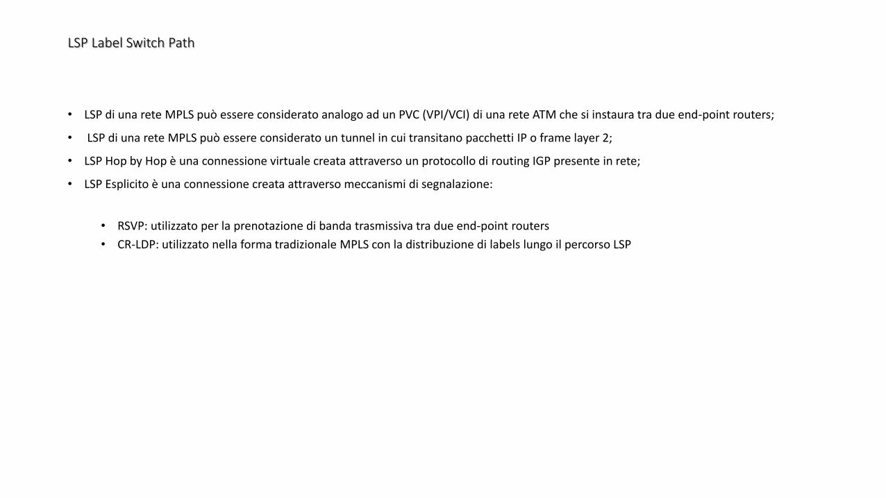
• LSP di una rete MPLS può essere considerato analogo ad un PVC (VPI/VCI) di una rete ATM che si instaura tra due end-point routers;
• LSP di una rete MPLS può essere considerato un tunnel in cui transitano pacchetti IP o frame layer 2;
• LSP Hop by Hop è una connessione virtuale creata attraverso un protocollo di routing IGP presente in rete;
• LSP Esplicito è una connessione creata attraverso meccanismi di segnalazione:
• RSVP: utilizzato per la prenotazione di banda trasmissiva tra due end-point routers
• CR-LDP: utilizzato nella forma tradizionale MPLS con la distribuzione di labels lungo il percorso LSP
MPLS VPN-L2 application
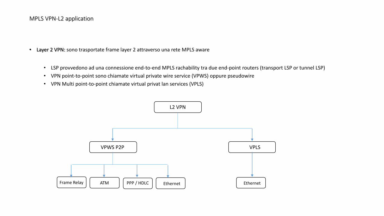
• Layer 2 VPN: sono trasportate frame layer 2 attraverso una rete MPLS aware
• LSP provvedono ad una connessione end-to-end MPLS rachability tra due end-point routers (transport LSP or tunnel LSP)
• VPN point-to-point sono chiamate virtual private wire service (VPWS) oppure pseudowire
• VPN Multi point-to-point chiamate virtual privat lan services (VPLS)
L2 VPN
VPWS P2P VPLS
Frame Relay ATM PPP / HDLC Ethernet Ethernet
MPLS VPN-L2 application
Sia VPWS che VPLS possono essere create attraverso il metodo Kompella oppure Martini; in entrambi i metodi l’LSP è costruito tra due PE attraverso il protocollo LDP.
I circuiti L2 pseudowire con il metodo Kompella il trasporto delle labels è segnalato via LDP a differenza della VC (virtual circuit) label segnalata via MP-BGP; mentre con il metodo Martini entrambe le labels via LDP.
Il PE routers MPLS, collegato al CE customer devices, analizza la frame ethernet in ingresso e identifica quale egress router PE è usato per il trasporto della frame (primo lookup); il secondo lookup determina l’interfaccia egress presso il router PE egress
I pacchetti MPLS Layer 2 utilizzano due labels:
• Outer Label (topmost) utizzata per raggiungere il devices egress (di uscita)
• Inner Label (VC label) utilizzata per identificare il circuito pseudowire at Egress router PE
VPWS può trasportare qualsiasi payload layer 2; VPLS trasporta solo frame ethernet.
MPLS VPN-L2 application
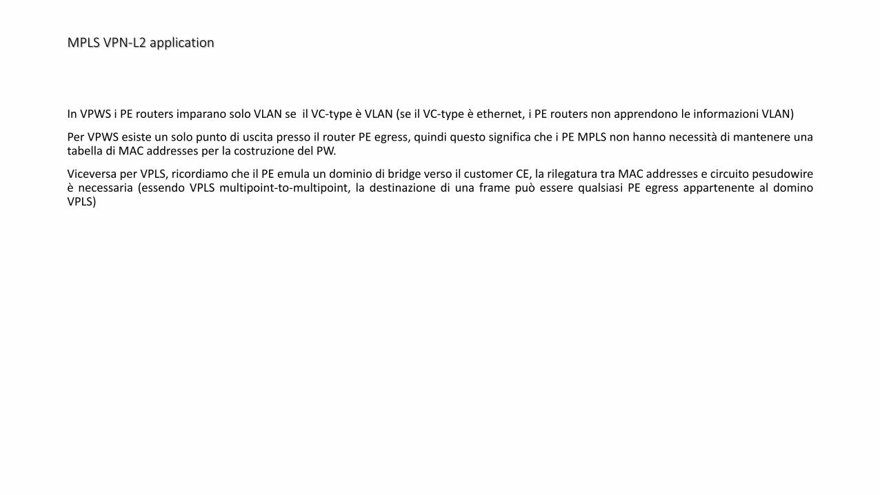
In VPWS i PE routers imparano solo VLAN se il VC-type è VLAN (se il VC-type è ethernet, i PE routers non apprendono le informazioni VLAN)
Per VPWS esiste un solo punto di uscita presso il router PE egress, quindi questo significa che i PE MPLS non hanno necessità di mantenere unatabella di MAC addresses per la costruzione del PW.
Viceversa per VPLS, ricordiamo che il PE emula un dominio di bridge verso il customer CE, la rilegatura tra MAC addresses e circuito pesudowireè necessaria (essendo VPLS multipoint-to-multipoint, la destinazione di una frame può essere qualsiasi PE egress appartenente al dominoVPLS)
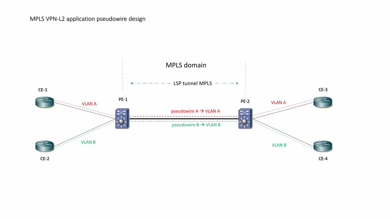
MPLS VPN-L2 application pseudowire design
VLAN A
VLAN B
LSP tunnel MPLS
pseudowire A VLAN A
pseudowire B VLAN B
VLAN A
VLAN B
CE-1
CE-2
CE-3
CE-4
PE-1 PE-2
MPLS domain
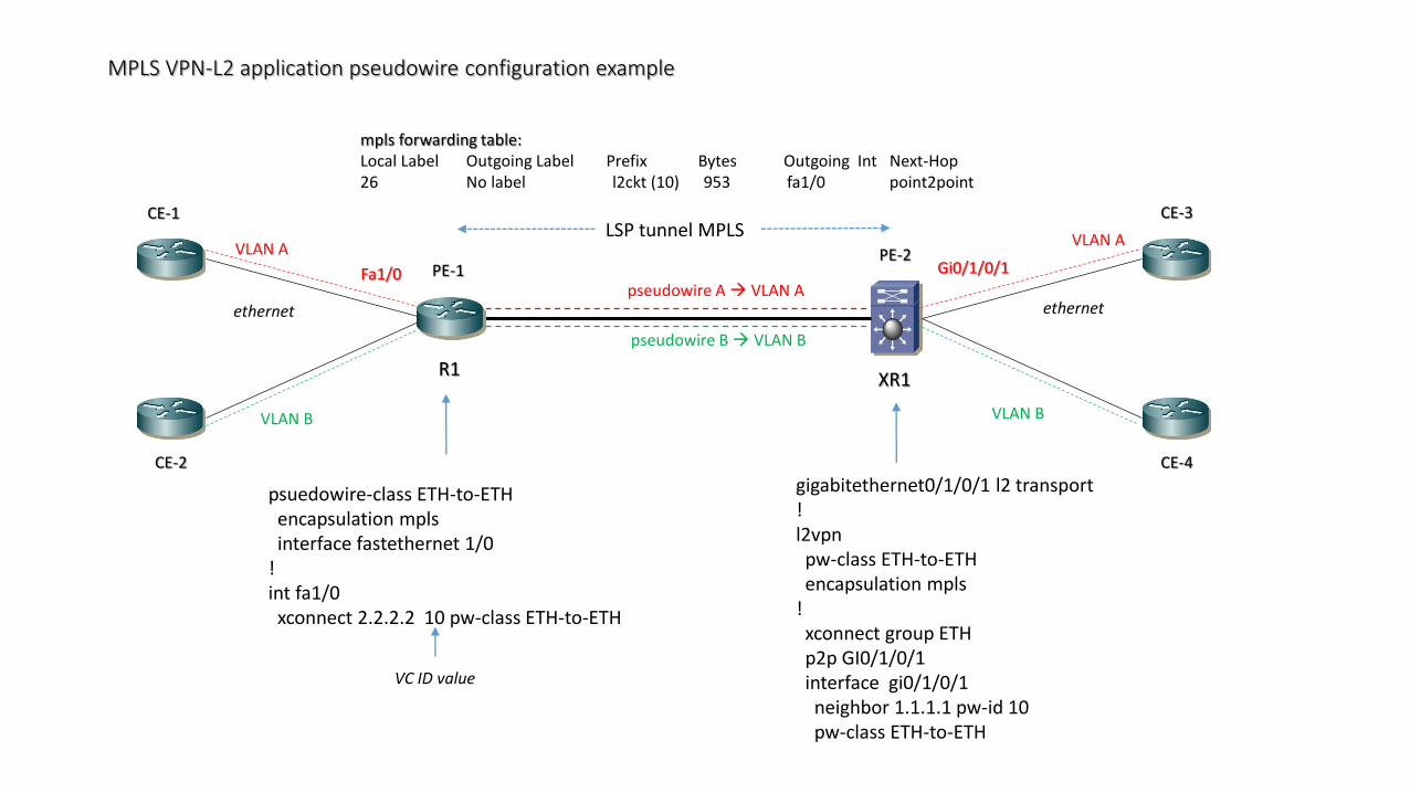
MPLS VPN-L2 application pseudowire configuration example
VLAN A
VLAN B
pseudowire A VLAN A
pseudowire B VLAN B
VLAN A
VLAN B
CE-1
CE-2
CE-3
CE-4
PE-1PE-2
R1XR1
Fa1/0 Gi0/1/0/1
ethernet ethernet
psuedowire-class ETH-to-ETHencapsulation mplsinterface fastethernet 1/0
!int fa1/0xconnect 2.2.2.2 10 pw-class ETH-to-ETH
VC ID value
gigabitethernet0/1/0/1 l2 transport!l2vpnpw-class ETH-to-ETHencapsulation mpls
!xconnect group ETHp2p GI0/1/0/1interface gi0/1/0/1neighbor 1.1.1.1 pw-id 10pw-class ETH-to-ETH
mpls forwarding table:Local Label Outgoing Label Prefix Bytes Outgoing Int Next-Hop26 No label l2ckt (10) 953 fa1/0 point2point
LSP tunnel MPLS
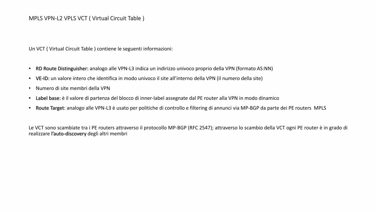
MPLS VPN-L2 VPLS VCT ( Virtual Circuit Table )
Un VCT ( Virtual Circuit Table ) contiene le seguenti informazioni:
• RD Route Distinguisher: analogo alle VPN-L3 indica un indirizzo univoco proprio della VPN (formato AS:NN)
• VE-ID: un valore intero che identifica in modo univoco il site all’interno della VPN (il numero della site)
• Numero di site membri della VPN
• Label base: è il valore di partenza del blocco di inner-label assegnate dal PE router alla VPN in modo dinamico
• Route Target: analogo alle VPN-L3 è usato per politiche di controllo e filtering di annunci via MP-BGP da parte dei PE routers MPLS
Le VCT sono scambiate tra i PE routers attraverso il protocollo MP-BGP (RFC 2547); attraverso lo scambio della VCT ogni PE router è in grado direalizzare l’auto-discovery degli altri membri
MPLS VPN-L2 VPLS VFT (VPLS Forwarding DataBase)
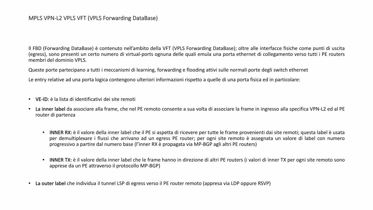
Il FBD (Forwarding DataBase) è contenuto nell’ambito della VFT (VPLS Forwarding DataBase); oltre alle interfacce fisiche come punti di uscita(egress), sono presenti un certo numero di virtual-ports ognuna delle quali emula una porta ethernet di collegamento verso tutti i PE routersmembri del dominio VPLS.
Queste porte partecipano a tutti i meccanismi di learning, forwarding e flooding attivi sulle normali porte degli switch ethernet
Le entry relative ad una porta logica contengono ulteriori informazioni rispetto a quelle di una porta fisica ed in particolare:
• VE-ID: è la lista di identificativi dei site remoti
• La inner label da associare alla frame, che nel PE remoto consente a sua volta di associare la frame in ingresso alla specifica VPN-L2 ed al PErouter di partenza
• INNER RX: è il valore della inner label che il PE si aspetta di ricevere per tutte le frame provenienti dai site remoti; questa label è usataper demultiplexare i flussi che arrivano ad un egress PE router; per ogni site remoto è assegnata un valore di label con numeroprogressivo a partire dal numero base (l’inner RX è propagata via MP-BGP agli altri PE routers)
• INNER TX: è il valore della inner label che le frame hanno in direzione di altri PE routers (i valori di inner TX per ogni site remoto sonoapprese da un PE attraverso il protocollo MP-BGP)
• La outer label che individua il tunnel LSP di egress verso il PE router remoto (appresa via LDP oppure RSVP)
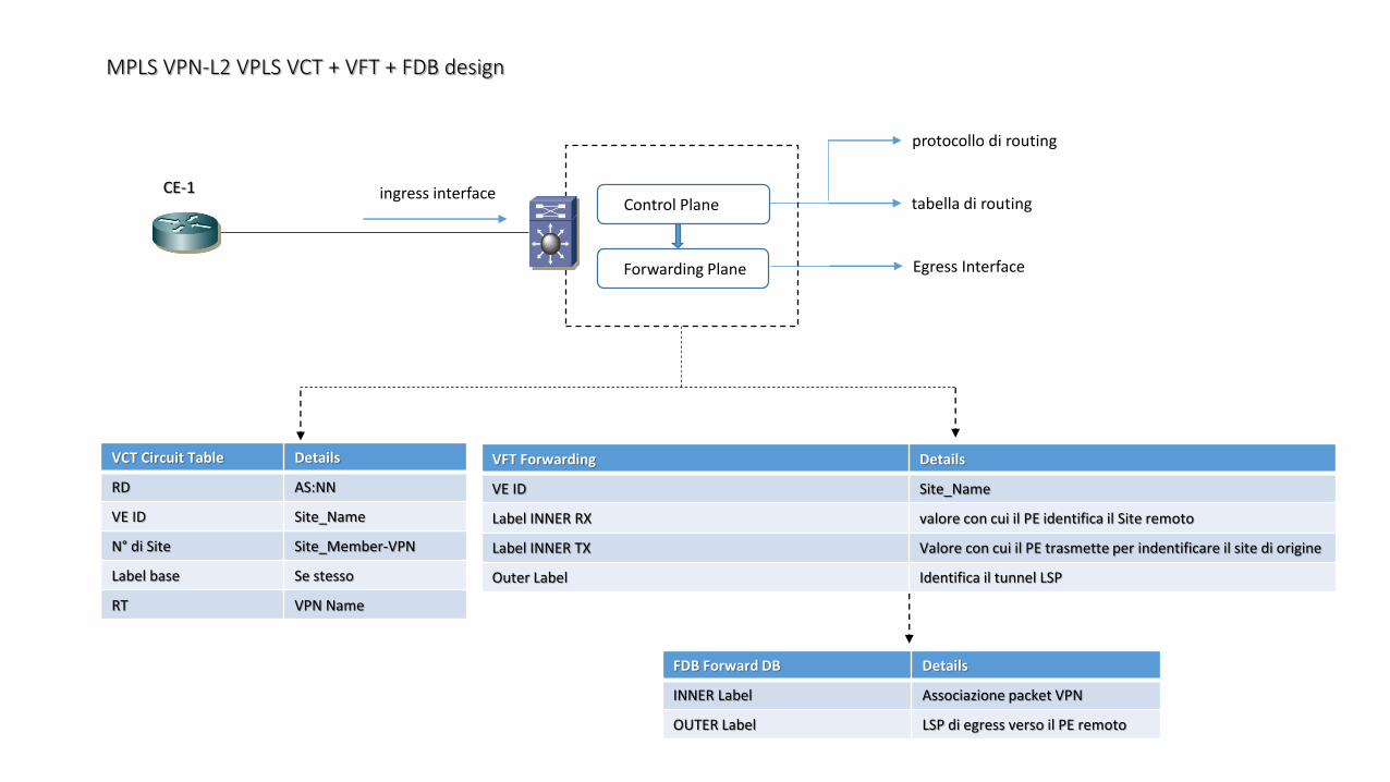
MPLS VPN-L2 VPLS VCT + VFT + FDB design
CE-1Control Plane
protocollo di routing
tabella di routing
Forwarding Plane Egress Interface
VCT Circuit Table Details
RD AS:NN
VE ID Site_Name
N° di Site Site_Member-VPN
Label base Se stesso
RT VPN Name
VFT Forwarding Details
VE ID Site_Name
Label INNER RX valore con cui il PE identifica il Site remoto
Label INNER TX Valore con cui il PE trasmette per indentificare il site di origine
Outer Label Identifica il tunnel LSP
FDB Forward DB Details
INNER Label Associazione packet VPN
OUTER Label LSP di egress verso il PE remoto
ingress interface
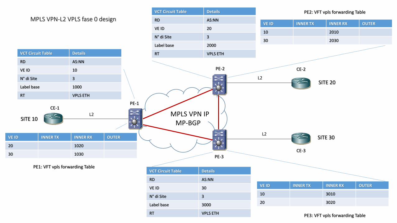
MPLS VPN-L2 VPLS fase 0 design
CE-1
CE-2
CE-3
PE-1
PE-2
PE-3
VCT Circuit Table Details
RD AS:NN
VE ID 10
N° di Site 3
Label base 1000
RT VPLS ETH
VCT Circuit Table Details
RD AS:NN
VE ID 20
N° di Site 3
Label base 2000
RT VPLS ETH
VCT Circuit Table Details
RD AS:NN
VE ID 30
N° di Site 3
Label base 3000
RT VPLS ETH
VE ID INNER TX INNER RX OUTER
20 1020
30 1030
VE ID INNER TX INNER RX OUTER
10 2010
30 2030
VE ID INNER TX INNER RX OUTER
10 3010
20 3020
MPLS VPN IPMP-BGP
SITE 10
SITE 20
SITE 30
L2
L2
L2
PE1: VFT vpls forwarding Table
PE2: VFT vpls forwarding Table
PE3: VFT vpls forwarding Table
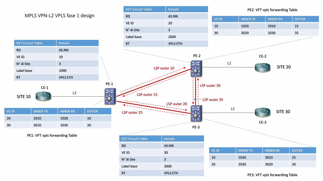
MPLS VPN-L2 VPLS fase 1 design
CE-1
CE-2
CE-3
PE-1
PE-2
PE-3
VCT Circuit Table Details
RD AS:NN
VE ID 10
N° di Site 3
Label base 1000
RT VPLS ETH
VCT Circuit Table Details
RD AS:NN
VE ID 20
N° di Site 3
Label base 2000
RT VPLS ETH
VCT Circuit Table Details
RD AS:NN
VE ID 30
N° di Site 3
Label base 3000
RT VPLS ETH
VE ID INNER TX INNER RX OUTER
20 2010 1020 10
30 3010 1030 20
VE ID INNER TX INNER RX OUTER
10 1020 2010 15
30 3020 2030 35
VE ID INNER TX INNER RX OUTER
10 1030 3010 25
20 2030 3020 30
SITE 10
SITE 20
SITE 30
L2
L2
L2
LSP outer 10
LSP outer 15
LSP outer 25
LSP outer 20LSP outer 35
LSP outer 30
PE2: VFT vpls forwarding Table
PE1: VFT vpls forwarding Table
PE3: VFT vpls forwarding Table
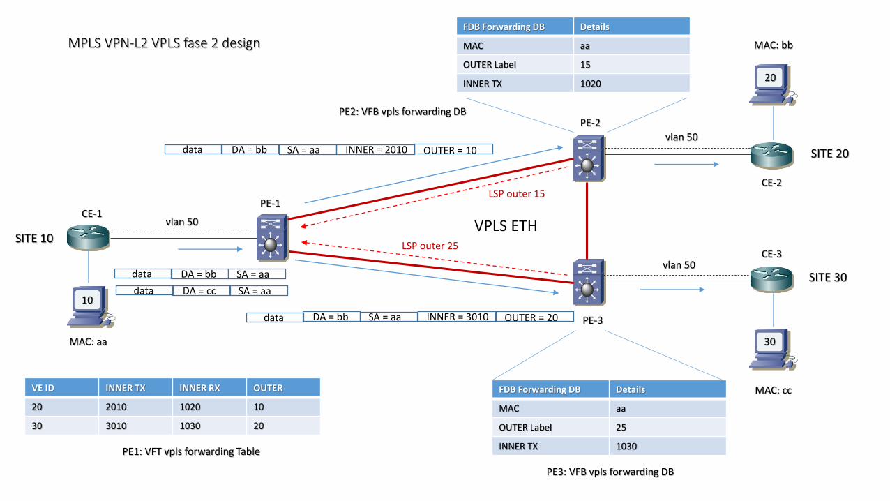
MPLS VPN-L2 VPLS fase 2 design
CE-1
CE-2
CE-3
PE-1
PE-2
PE-3
SITE 10
SITE 20
SITE 30
10
20
30MAC: aa
MAC: bb
MAC: cc
vlan 50
vlan 50
vlan 50SA = aaDA = bbdata
SA = aaDA = bbdata INNER = 2010 OUTER = 10
VE ID INNER TX INNER RX OUTER
20 2010 1020 10
30 3010 1030 20
PE1: VFT vpls forwarding Table
SA = aaDA = ccdata
SA = aaDA = bbdata INNER = 3010 OUTER = 20
FDB Forwarding DB Details
MAC aa
OUTER Label 15
INNER TX 1020
LSP outer 15
LSP outer 25
FDB Forwarding DB Details
MAC aa
OUTER Label 25
INNER TX 1030
VPLS ETH
PE2: VFB vpls forwarding DB
PE3: VFB vpls forwarding DB
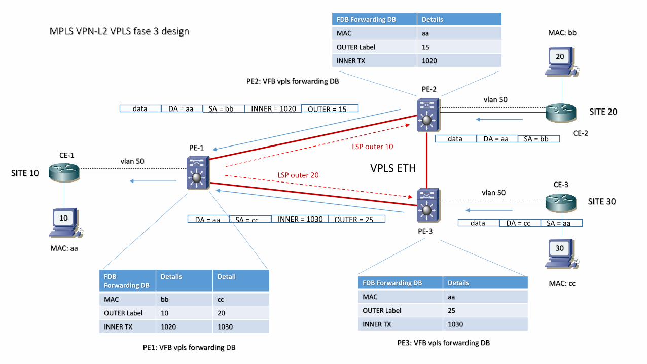
MPLS VPN-L2 VPLS fase 3 design
CE-1
CE-2
CE-3
PE-1
PE-2
PE-3
SITE 10
SITE 20
SITE 30
10
20
30MAC: aa
MAC: bb
MAC: cc
vlan 50
vlan 50
vlan 50
SA = bbDA = aadata
SA = bbDA = aadata INNER = 1020 OUTER = 15
SA = aaDA = ccdataSA = ccDA = aa INNER = 1030 OUTER = 25
FDB Forwarding DB Details
MAC aa
OUTER Label 15
INNER TX 1020
FDB Forwarding DB Details
MAC aa
OUTER Label 25
INNER TX 1030
VPLS ETH
FDBForwarding DB
Details Detail
MAC bb cc
OUTER Label 10 20
INNER TX 1020 1030
LSP outer 10
LSP outer 20
PE2: VFB vpls forwarding DB
PE3: VFB vpls forwarding DBPE1: VFB vpls forwarding DB
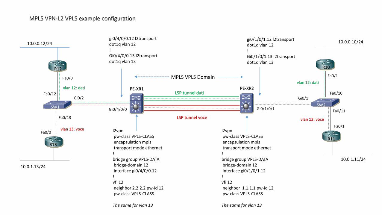
MPLS VPN-L2 VPLS example configuration
Fa0/0
Fa0/0
Fa0/12
Fa0/13
Gi0/2
Gi0/4/0/0
Fa0/1
Fa0/1
Fa0/11
Fa0/10Gi0/1
Gi0/1/0/1
PE-XR1 PE-XR2
vlan 13: voce
vlan 12: datiLSP tunnel dati
LSP tunnel voce
10.0.1.13/24
10.0.0.12/24 10.0.0.10/24
10.0.1.11/24
R12
R13
R10
R11
SW1 SW2
gi0/1/0/1.12 l2transportdot1q vlan 12!Gi0/1/0/1.13 l2transportdot1q vlan 13
gi0/4/0/0.12 l2transportdot1q vlan 12!Gi0/4/0/0.13 l2transportdot1q vlan 13
l2vpn pw-class VPLS-CLASSencapsulation mplstransport mode ethernet
!bridge group VPLS-DATAbridge-domain 12interface gi0/4/0/0.12
!vfi 12neighbor 2.2.2.2 pw-id 12pw-class VPLS-CLASS
The same for vlan 13
l2vpn pw-class VPLS-CLASSencapsulation mplstransport mode ethernet
!bridge group VPLS-DATAbridge-domain 12interface gi0/1/0/1.12
!vfi 12neighbor 1.1.1.1 pw-id 12pw-class VPLS-CLASS
The same for vlan 13
vlan 12: dati
vlan 13: voce
MPLS VPLS Domain

MPLS VPN-L2 VPLS Spanning Tree Avoidance
Non c’è Spanning Tree Protocol all’interno del dominio Core in un Services Provider MPLS per ragioni di loop avoidance in VPLS
La regola split-horizon nel core SP è abilitata di default e nessuna configurazione è necessaria, quindi se una frame customer è ricevuta da uncircuito pseudowire, questa non è trasmessa dietro via altro PW
CE-A
CE-B
CE-C
PE-A
PE-B
PE-C
PE-D
full-mesh VPLS PW
split-horizon rule applied
split-horizon rule applied
frame customer frame customer frame customer
frame customer
frame customer
frame customer
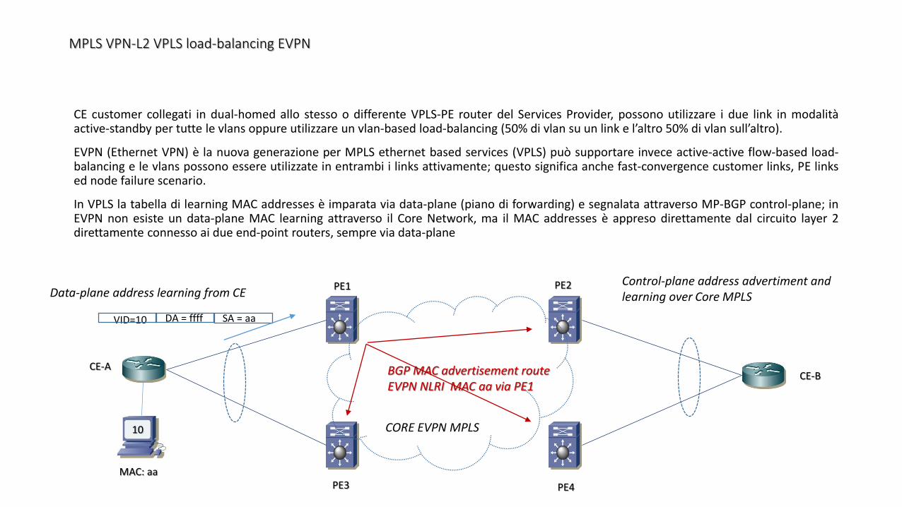
MPLS VPN-L2 VPLS load-balancing EVPN
CE customer collegati in dual-homed allo stesso o differente VPLS-PE router del Services Provider, possono utilizzare i due link in modalitàactive-standby per tutte le vlans oppure utilizzare un vlan-based load-balancing (50% di vlan su un link e l’altro 50% di vlan sull’altro).
EVPN (Ethernet VPN) è la nuova generazione per MPLS ethernet based services (VPLS) può supportare invece active-active flow-based load-balancing e le vlans possono essere utilizzate in entrambi i links attivamente; questo significa anche fast-convergence customer links, PE linksed node failure scenario.
In VPLS la tabella di learning MAC addresses è imparata via data-plane (piano di forwarding) e segnalata attraverso MP-BGP control-plane; inEVPN non esiste un data-plane MAC learning attraverso il Core Network, ma il MAC addresses è appreso direttamente dal circuito layer 2direttamente connesso ai due end-point routers, sempre via data-plane
10
MAC: aa
SA = aaDA = ffffVID=10
Data-plane address learning from CEControl-plane address advertiment and learning over Core MPLS
BGP MAC advertisement routeEVPN NLRI MAC aa via PE1
PE3
PE2PE1
PE4
CE-ACE-B
CORE EVPN MPLS
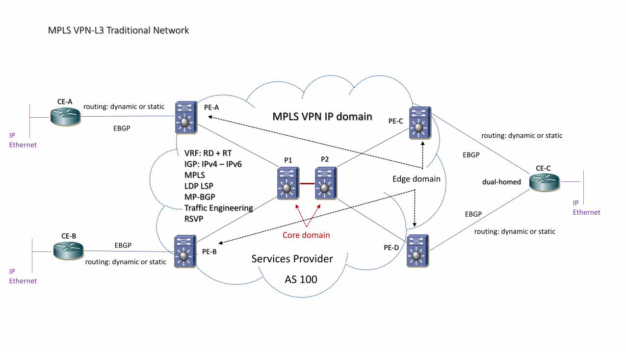
MPLS VPN-L3 Traditional Network
CE-A
CE-B
CE-C
PE-A
PE-B
PE-C
PE-D
VRF: RD + RTIGP: IPv4 – IPv6MPLSLDP LSPMP-BGPTraffic EngineeringRSVP
Services Provider
P1 P2
Core domain
Edge domain dual-homed
routing: dynamic or static
routing: dynamic or static
routing: dynamic or static
routing: dynamic or static
IPEthernet
IPEthernet
IPEthernet
MPLS VPN IP domain
AS 100
EBGP
EBGP
EBGP
EBGP
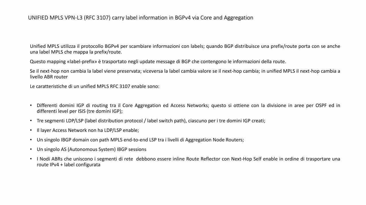
UNIFIED MPLS VPN-L3 (RFC 3107) carry label information in BGPv4 via Core and Aggregation
Unified MPLS utilizza il protocollo BGPv4 per scambiare informazioni con labels; quando BGP distribuisce una prefix/route porta con se ancheuna label MPLS che mappa la prefix/route.
Questo mapping «label-prefix» è trasportato negli update message di BGP che contengono le informazioni della route.
Se il next-hop non cambia la label viene preservata; viceversa la label cambia valore se il next-hop cambia; in unified MPLS il next-hop cambia alivello ABR router
Le caratteristiche di un unified MPLS RFC 3107 enable sono:
• Differenti domini IGP di routing tra il Core Aggregation ed Access Networks; questo si ottiene con la divisione in aree per OSPF ed indifferenti level per ISIS (tre domini IGP);
• Tre segmenti LDP/LSP (label distribution protocol / label switch path), ciascuno per i tre domini IGP creati;
• Il layer Access Network non ha LDP/LSP enable;
• Un singolo IBGP domain con path MPLS end-to-end LSP tra i livelli di Aggregation Node Routers;
• Un singolo AS (Autonomous System) IBGP sessions
• I Nodi ABRs che uniscono i segmenti di rete debbono essere inline Route Reflector con Next-Hop Self enable in ordine di trasportare unaroute IPv4 + label configurata
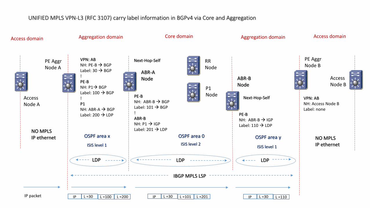
UNIFIED MPLS VPN-L3 (RFC 3107) carry label information in BGPv4 via Core and Aggregation
Core domainAggregation domain Aggregation domain
OSPF area 0OSPF area x OSPF area y
ABR-ANode ABR-B
Node
RRNode
ISIS level 2 ISIS level 1 ISIS level 1
IBGP MPLS LSP
Access domain Access domain
LDP
PE AggrNode A
PE AggrNode B
P1Node
NO MPLSIP ethernet NO MPLS
IP ethernet
AccessNode A
AccessNode B
LDP LDP
Next-Hop-Self
Next-Hop-Self
IP packet
VPN: ABNH: PE-B BGPLabel: 30 BGP!PE-BNH: P1 BGPLabel: 100 BGP!P1NH: ABR-A BGPLabel: 200 LDP
VPN: ABNH: Access Node BLabel: none
PE-BNH: ABR-B BGPLabel: 101 BGP!ABR-BNH: P1 IGPLabel: 201 LDP
PE-BNH: ABR-B IGPLabel: 110 LDP
L =30IP L =100 L =200 L =30IP L =101 L =201 L =30IP L =110
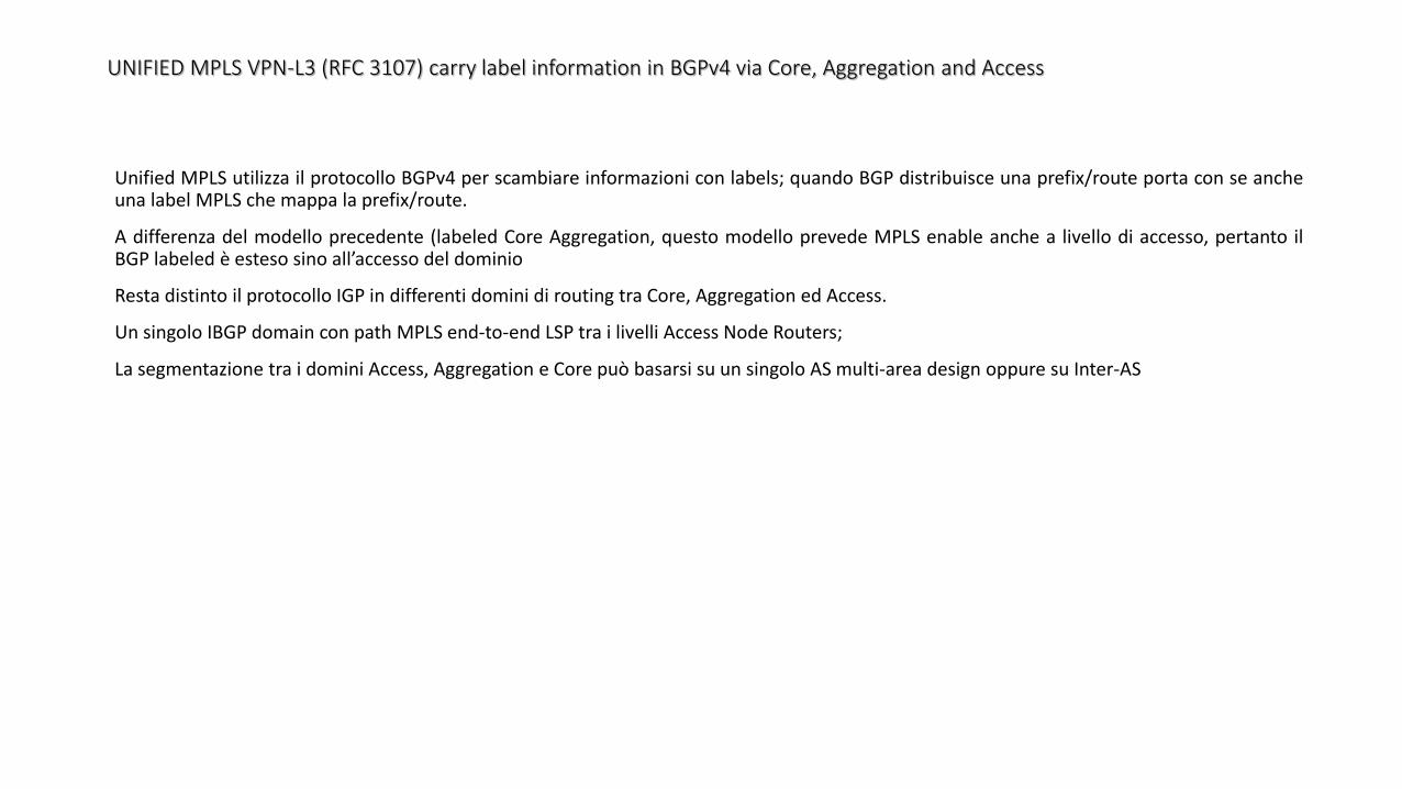
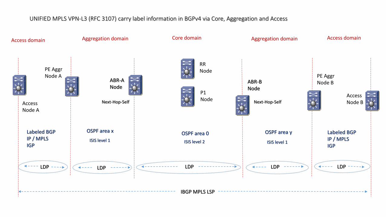
UNIFIED MPLS VPN-L3 (RFC 3107) carry label information in BGPv4 via Core, Aggregation and Access
Unified MPLS utilizza il protocollo BGPv4 per scambiare informazioni con labels; quando BGP distribuisce una prefix/route porta con se ancheuna label MPLS che mappa la prefix/route.
A differenza del modello precedente (labeled Core Aggregation, questo modello prevede MPLS enable anche a livello di accesso, pertanto ilBGP labeled è esteso sino all’accesso del dominio
Resta distinto il protocollo IGP in differenti domini di routing tra Core, Aggregation ed Access.
Un singolo IBGP domain con path MPLS end-to-end LSP tra i livelli Access Node Routers;
La segmentazione tra i domini Access, Aggregation e Core può basarsi su un singolo AS multi-area design oppure su Inter-AS
UNIFIED MPLS VPN-L3 (RFC 3107) carry label information in BGPv4 via Core, Aggregation and Access
Core domainAggregation domain Aggregation domain
OSPF area 0OSPF area x OSPF area y
ABR-ANode
ABR-BNode
RRNode
ISIS level 2 ISIS level 1 ISIS level 1
IBGP MPLS LSP
Access domain Access domain
LDP
PE AggrNode A PE Aggr
Node B
P1Node
AccessNode A
AccessNode B
LDP LDP
Next-Hop-Self Next-Hop-Self
LDP
Labeled BGPIP / MPLSIGP
Labeled BGPIP / MPLSIGP
LDP

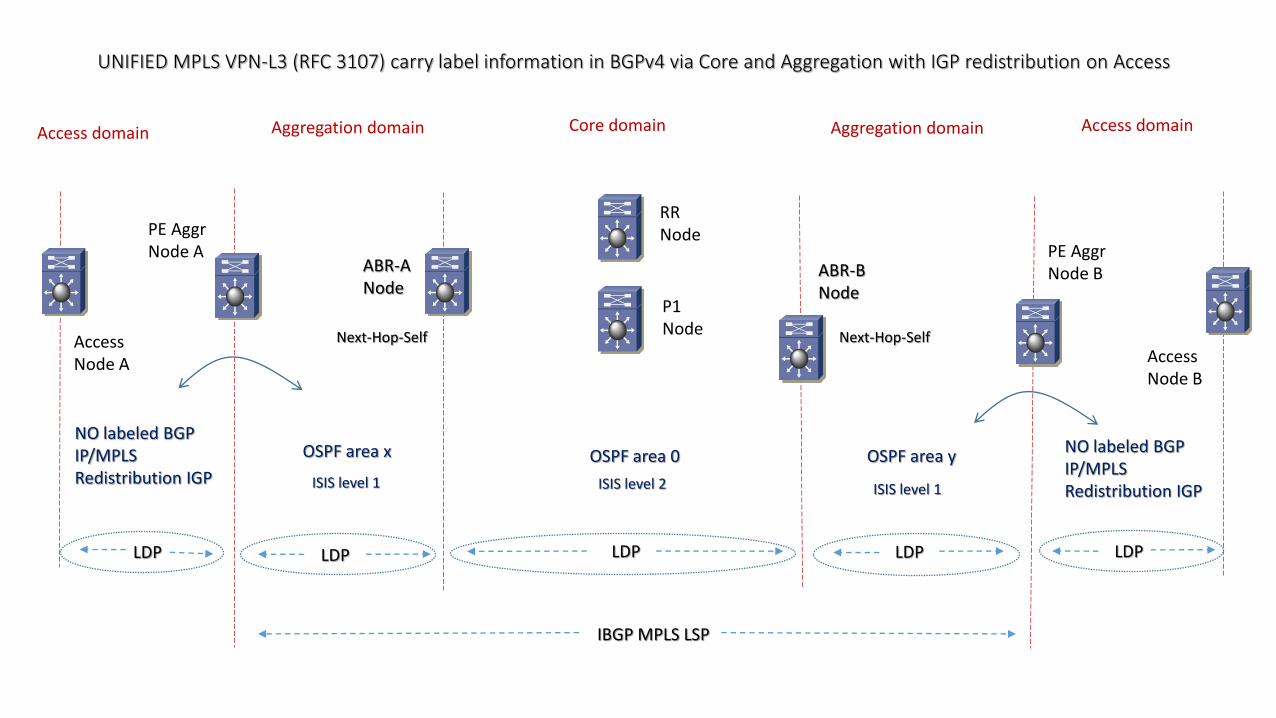
UNIFIED MPLS VPN-L3 (RFC 3107) carry label information in BGPv4 via Core and Aggregation with IGP redistribution on Access
Unified MPLS utilizza il protocollo BGPv4 per scambiare informazioni con labels; quando BGP distribuisce una prefix/route porta con se ancheuna label MPLS che mappa la prefix/route.
In questo modello il livello Access lavora con IP/MPLS ma non con labeled BGP; un processo di Redistribution è performato a livello diAggregation Node.
L’indirizzo di loopback del Access Node è redistribuito dentro IBGP domain.
Il dominio Core Aggregation è esteso a livello di Access con la redistribuzione dell’Access IGP dentro il dominio IBGP e la redistribuzione di tuttele necessarie labeled IBGP prefix dentro il dominio Access IGP (via BGP comminity)
UNIFIED MPLS VPN-L3 (RFC 3107) carry label information in BGPv4 via Core and Aggregation with IGP redistribution on Access
Core domainAggregation domain Aggregation domain
OSPF area 0OSPF area x OSPF area y
ABR-ANode
ABR-BNode
RRNode
ISIS level 2 ISIS level 1 ISIS level 1
IBGP MPLS LSP
Access domain Access domain
LDP
PE AggrNode A PE Aggr
Node B
P1Node
AccessNode A Access
Node B
LDP LDP
Next-Hop-Self Next-Hop-Self
LDP
NO labeled BGPIP/MPLSRedistribution IGP
NO labeled BGPIP/MPLSRedistribution IGP
LDP
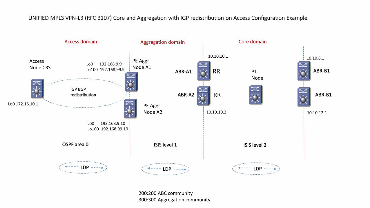
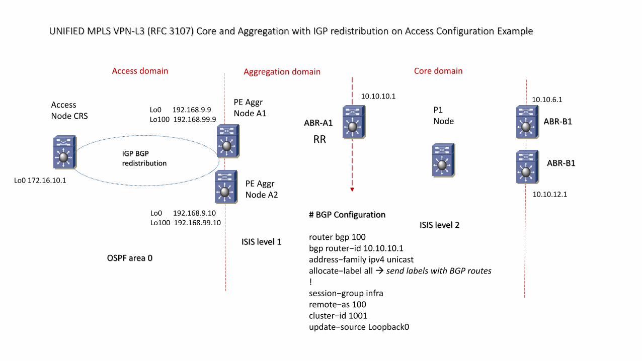
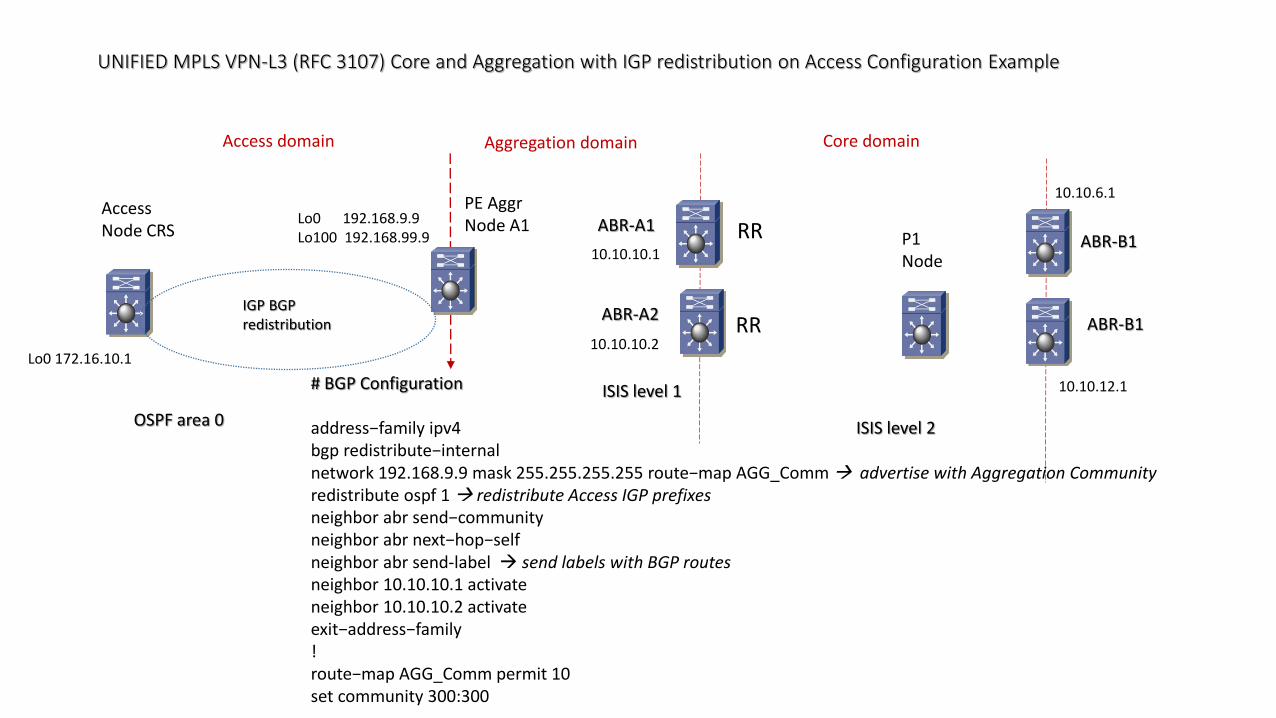
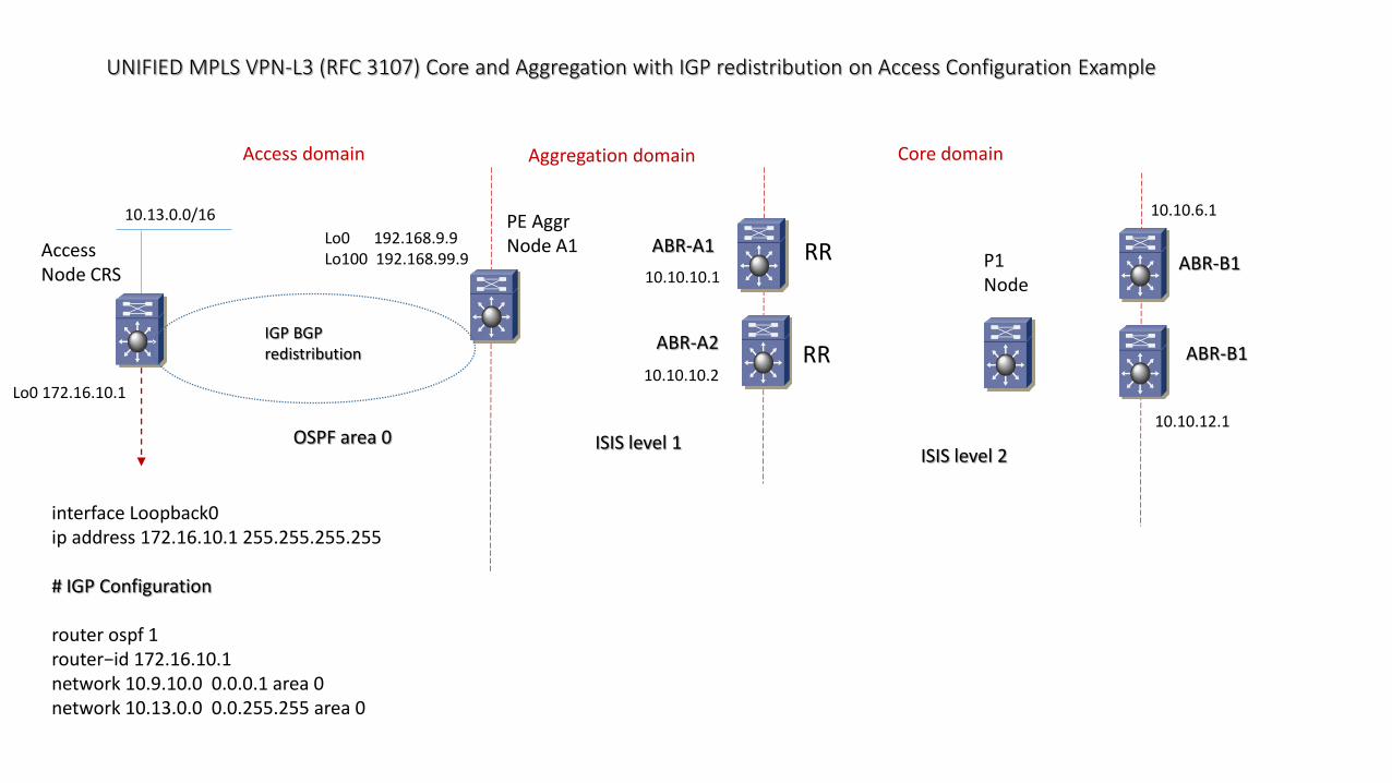
UNIFIED MPLS VPN-L3 (RFC 3107) Core and Aggregation with IGP redistribution on Access Configuration Example
AccessNode CRS
ABR-A1 P1Node
ABR-B1
LDP
IGP BGPredistribution
Core domainAggregation domain
ISIS level 2ISIS level 1OSPF area 0
LDP LDP
PE AggrNode A1
PE AggrNode A2
ABR-A2 ABR-B1
Lo0 192.168.9.9Lo100 192.168.99.9
Lo0 192.168.9.10Lo100 192.168.99.10
10.10.10.1
10.10.10.2
10.10.6.1
10.10.12.1
Access domain
200:200 ABC community300:300 Aggregation community
RR
RRLo0 172.16.10.1
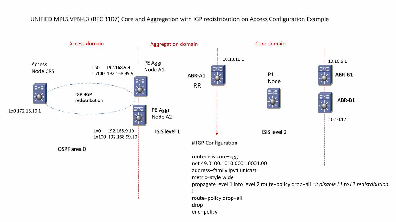
UNIFIED MPLS VPN-L3 (RFC 3107) Core and Aggregation with IGP redistribution on Access Configuration Example
AccessNode CRS
ABR-A1 P1Node
ABR-B1
IGP BGPredistribution
Core domainAggregation domain
ISIS level 2ISIS level 1
OSPF area 0
PE AggrNode A1
PE AggrNode A2
ABR-B1
Lo0 192.168.9.9Lo100 192.168.99.9
Lo0 192.168.9.10Lo100 192.168.99.10
10.10.10.1 10.10.6.1
10.10.12.1
Access domain
# IGP Configuration
router isis core−aggnet 49.0100.1010.0001.0001.00address−family ipv4 unicastmetric−style widepropagate level 1 into level 2 route−policy drop−all disable L1 to L2 redistribution!route−policy drop−alldropend−policy
RR
Lo0 172.16.10.1

UNIFIED MPLS VPN-L3 (RFC 3107) Core and Aggregation with IGP redistribution on Access Configuration Example
AccessNode CRS
ABR-A1
P1Node ABR-B1
IGP BGPredistribution
Core domainAggregation domain
ISIS level 2ISIS level 1
OSPF area 0
PE AggrNode A1
PE AggrNode A2
ABR-B1
Lo0 192.168.9.9Lo100 192.168.99.9
Lo0 192.168.9.10Lo100 192.168.99.10
10.10.10.1 10.10.6.1
10.10.12.1
Access domain
interface Loopback0ipv4 address 10.10.10.1 255.255.255.255passive!interface TenGigE0/0/0/1circuit−type level−2−only!interface TenGigE0/0/0/2circuit−type level−1
RR
Lo0 172.16.10.1
UNIFIED MPLS VPN-L3 (RFC 3107) Core and Aggregation with IGP redistribution on Access Configuration Example
AccessNode CRS
ABR-A1
P1Node ABR-B1
IGP BGPredistribution
Core domainAggregation domain
ISIS level 2
ISIS level 1
OSPF area 0
PE AggrNode A1
PE AggrNode A2
ABR-B1
Lo0 192.168.9.9Lo100 192.168.99.9
Lo0 192.168.9.10Lo100 192.168.99.10
10.10.10.1 10.10.6.1
10.10.12.1
Access domain
# BGP Configuration
router bgp 100bgp router−id 10.10.10.1address−family ipv4 unicastallocate−label all send labels with BGP routes!session−group infraremote−as 100cluster−id 1001update−source Loopback0
RR
Lo0 172.16.10.1
UNIFIED MPLS VPN-L3 (RFC 3107) Core and Aggregation with IGP redistribution on Access Configuration Example
AccessNode CRS
ABR-A1 P1Node
ABR-B1
IGP BGPredistribution
Core domainAggregation domain
ISIS level 2
ISIS level 1OSPF area 0
PE AggrNode A1
PE AggrNode A2
ABR-B1
Lo0 192.168.9.9Lo100 192.168.99.9
Lo0 192.168.9.10Lo100 192.168.99.10
10.10.10.1
10.10.6.1
10.10.12.1
Access domain
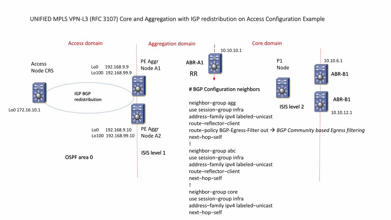
# BGP Configuration neighbors
neighbor−group agguse session−group infraaddress−family ipv4 labeled−unicastroute−reflector−clientroute−policy BGP-Egress-Filter out BGP Community based Egress filteringnext−hop−self!neighbor−group abcuse session−group infraaddress−family ipv4 labeled−unicastroute−reflector−clientnext−hop−self!neighbor−group coreuse session−group infraaddress−family ipv4 labeled−unicastnext−hop−self
RR
Lo0 172.16.10.1
UNIFIED MPLS VPN-L3 (RFC 3107) Core and Aggregation with IGP redistribution on Access Configuration Example
AccessNode CRS
ABR-A1 P1Node
ABR-B1
IGP BGPredistribution
Core domainAggregation domain
ISIS level 2ISIS level 1
OSPF area 0
PE AggrNode A1
PE AggrNode A2
ABR-B1
Lo0 192.168.9.9Lo100 192.168.99.9
Lo0 192.168.9.10Lo100 192.168.99.10
10.10.10.1 10.10.6.1
10.10.12.1
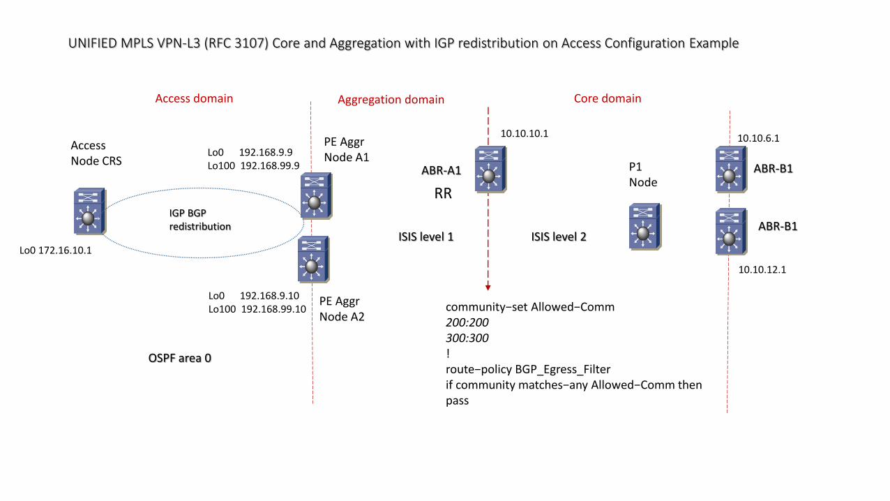
Access domain
community−set Allowed−Comm200:200300:300!route−policy BGP_Egress_Filterif community matches−any Allowed−Comm thenpass
RR
Lo0 172.16.10.1
UNIFIED MPLS VPN-L3 (RFC 3107) Core and Aggregation with IGP redistribution on Access Configuration Example
AccessNode CRS
ABR-A1 P1Node
ABR-B1
IGP BGPredistribution
Core domainAggregation domain
ISIS level 2
ISIS level 1
OSPF area 0
PE AggrNode A1
ABR-B1
Lo0 192.168.9.9Lo100 192.168.99.9
10.10.10.1
10.10.6.1
10.10.12.1
Access domain
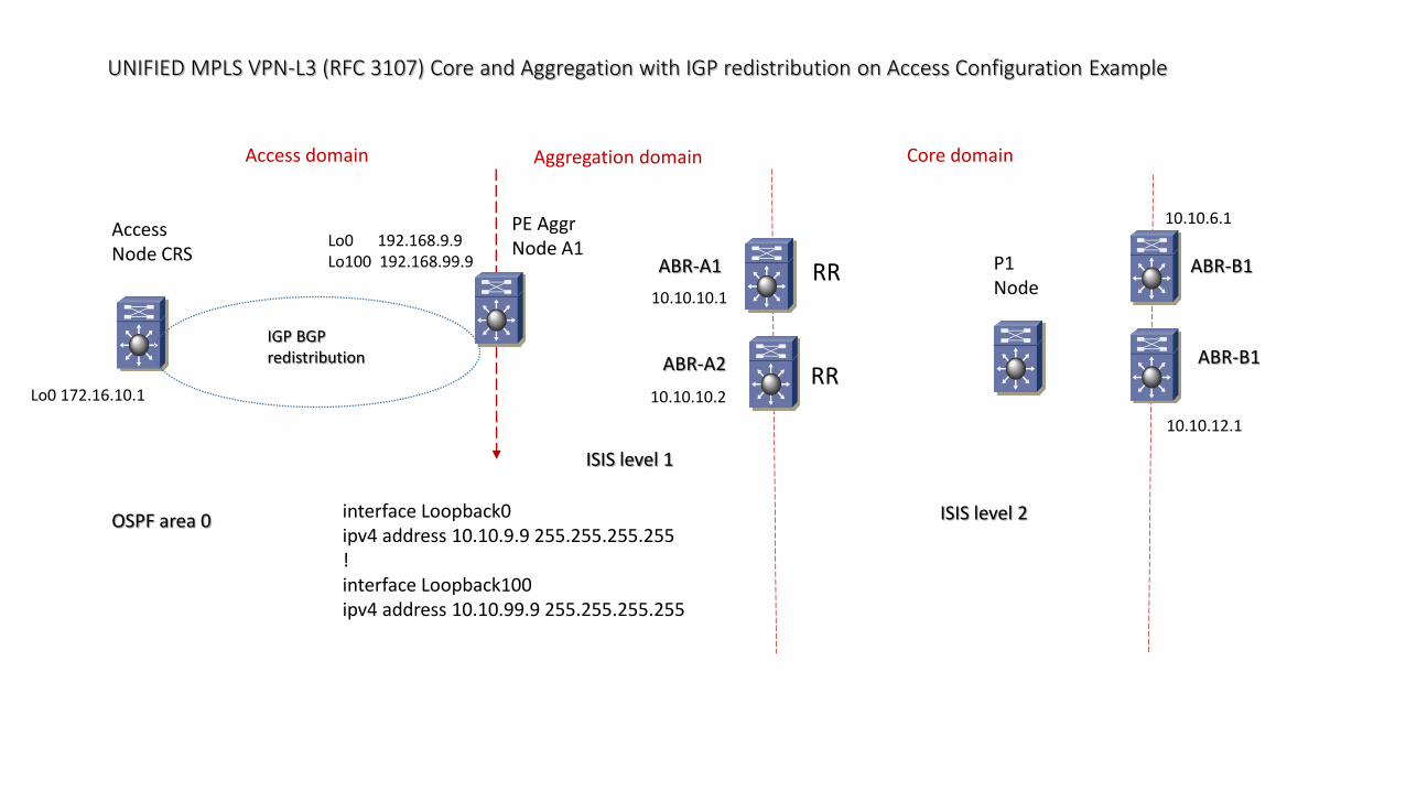
RR
interface Loopback0ipv4 address 10.10.9.9 255.255.255.255!interface Loopback100ipv4 address 10.10.99.9 255.255.255.255
ABR-A2RR
10.10.10.2Lo0 172.16.10.1
UNIFIED MPLS VPN-L3 (RFC 3107) Core and Aggregation with IGP redistribution on Access Configuration Example
AccessNode CRS P1
NodeABR-B1
IGP BGPredistribution
Core domainAggregation domain
ISIS level 2
ISIS level 1OSPF area 0
PE AggrNode A1
ABR-B1
Lo0 192.168.9.9Lo100 192.168.99.9
10.10.6.1
10.10.12.1
Access domain
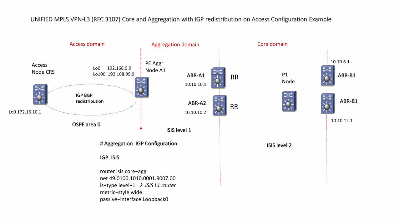
# Aggregation IGP Configuration
IGP: ISIS
router isis core−aggnet 49.0100.1010.0001.9007.00is−type level−1 ISIS L1 routermetric−style widepassive−interface Loopback0
ABR-A1
10.10.10.1
RR
ABR-A2RR
10.10.10.2Lo0 172.16.10.1
UNIFIED MPLS VPN-L3 (RFC 3107) Core and Aggregation with IGP redistribution on Access Configuration Example
AccessNode CRS P1
NodeABR-B1
IGP BGPredistribution
Core domainAggregation domain
ISIS level 2ISIS level 1OSPF area 0
PE AggrNode A1
ABR-B1
Lo0 192.168.9.9Lo100 192.168.99.9
10.10.6.1
10.10.12.1
Access domain
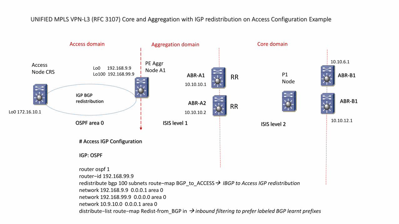
# Access IGP Configuration
IGP: OSPF
router ospf 1router−id 192.168.99.9redistribute bgp 100 subnets route−map BGP_to_ACCESS IBGP to Access IGP redistributionnetwork 192.168.9.9 0.0.0.1 area 0network 192.168.99.9 0.0.0.0 area 0network 10.9.10.0 0.0.0.1 area 0 distribute−list route−map Redist-from_BGP in inbound filtering to prefer labeled BGP learnt prefixes
ABR-A1
10.10.10.1
RR
ABR-A2RR
10.10.10.2Lo0 172.16.10.1
UNIFIED MPLS VPN-L3 (RFC 3107) Core and Aggregation with IGP redistribution on Access Configuration Example
AccessNode CRS P1
NodeABR-B1
IGP BGPredistribution
Core domainAggregation domain
ISIS level 2ISIS level 1OSPF area 0
PE AggrNode A1
ABR-B1
Lo0 192.168.9.9Lo100 192.168.99.9
10.10.6.1
10.10.12.1
Access domain
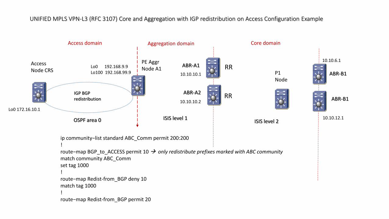
ip community−list standard ABC_Comm permit 200:200!route−map BGP_to_ACCESS permit 10 only redistribute prefixes marked with ABC communitymatch community ABC_Commset tag 1000!route−map Redist-from_BGP deny 10match tag 1000!route−map Redist-from_BGP permit 20
ABR-A1
10.10.10.1
RR
ABR-A2RR
10.10.10.2
Lo0 172.16.10.1
UNIFIED MPLS VPN-L3 (RFC 3107) Core and Aggregation with IGP redistribution on Access Configuration Example
AccessNode CRS P1
NodeABR-B1
IGP BGPredistribution
Core domainAggregation domain
ISIS level 2
ISIS level 1
OSPF area 0
Lo0 172.16.10.1
PE AggrNode A1
ABR-B1
Lo0 192.168.9.9Lo100 192.168.99.9
10.10.6.1
10.10.12.1
Access domain
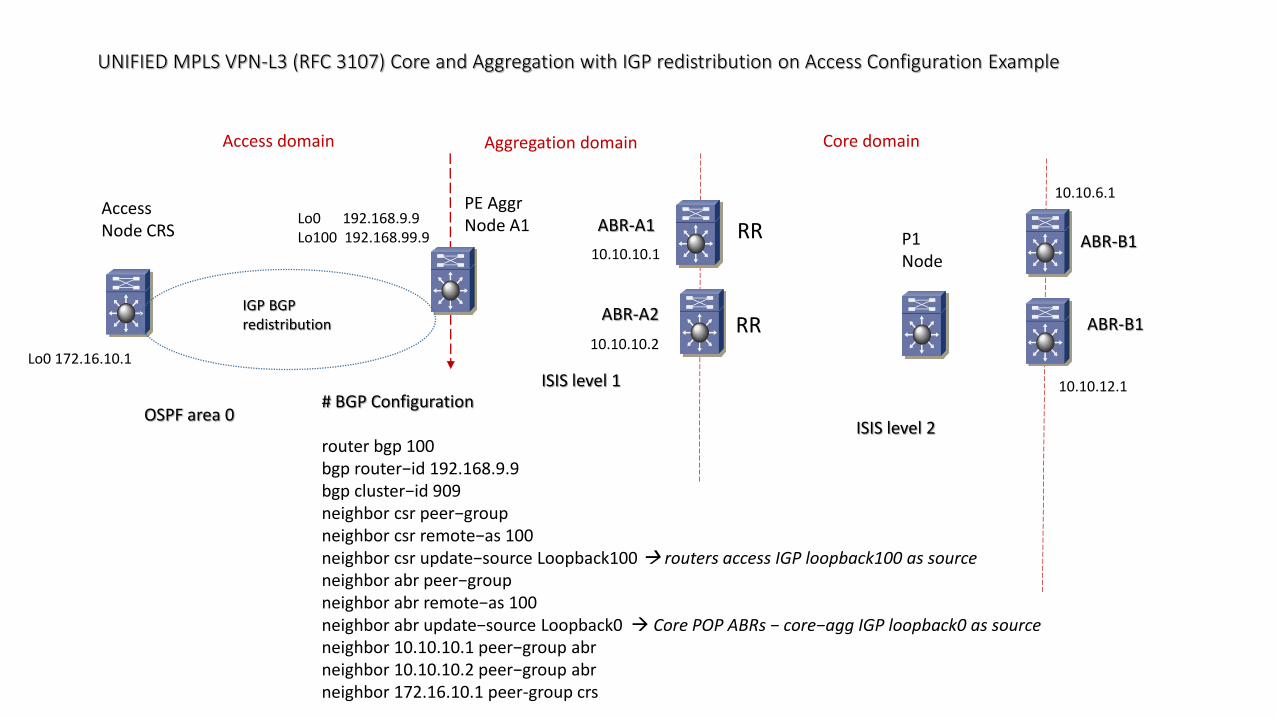
# BGP Configuration
router bgp 100bgp router−id 192.168.9.9bgp cluster−id 909neighbor csr peer−groupneighbor csr remote−as 100neighbor csr update−source Loopback100 routers access IGP loopback100 as sourceneighbor abr peer−groupneighbor abr remote−as 100neighbor abr update−source Loopback0 Core POP ABRs − core−agg IGP loopback0 as sourceneighbor 10.10.10.1 peer−group abrneighbor 10.10.10.2 peer−group abrneighbor 172.16.10.1 peer-group crs
ABR-A1
10.10.10.1
RR
ABR-A2RR
10.10.10.2
UNIFIED MPLS VPN-L3 (RFC 3107) Core and Aggregation with IGP redistribution on Access Configuration Example
AccessNode CRS P1
NodeABR-B1
IGP BGPredistribution
Core domainAggregation domain
ISIS level 2
ISIS level 1
OSPF area 0
PE AggrNode A1
ABR-B1
Lo0 192.168.9.9Lo100 192.168.99.9
10.10.6.1
10.10.12.1
Access domain
# BGP Configuration
address−family ipv4bgp redistribute−internalnetwork 192.168.9.9 mask 255.255.255.255 route−map AGG_Comm advertise with Aggregation Communityredistribute ospf 1 redistribute Access IGP prefixesneighbor abr send−communityneighbor abr next−hop−selfneighbor abr send-label send labels with BGP routesneighbor 10.10.10.1 activateneighbor 10.10.10.2 activateexit−address−family!route−map AGG_Comm permit 10set community 300:300
ABR-A1
10.10.10.1
RR
ABR-A2RR
10.10.10.2Lo0 172.16.10.1
UNIFIED MPLS VPN-L3 (RFC 3107) Core and Aggregation with IGP redistribution on Access Configuration Example
AccessNode CRS
P1Node
ABR-B1
IGP BGPredistribution
Core domainAggregation domain
ISIS level 2ISIS level 1OSPF area 0
PE AggrNode A1
ABR-B1
Lo0 192.168.9.9Lo100 192.168.99.9
10.10.6.1
10.10.12.1
Access domain
ABR-A1
10.10.10.1
RR
ABR-A2RR
10.10.10.2Lo0 172.16.10.1
interface Loopback0ip address 172.16.10.1 255.255.255.255
# IGP Configuration
router ospf 1router−id 172.16.10.1network 10.9.10.0 0.0.0.1 area 0network 10.13.0.0 0.0.255.255 area 0
10.13.0.0/16
Related Documents