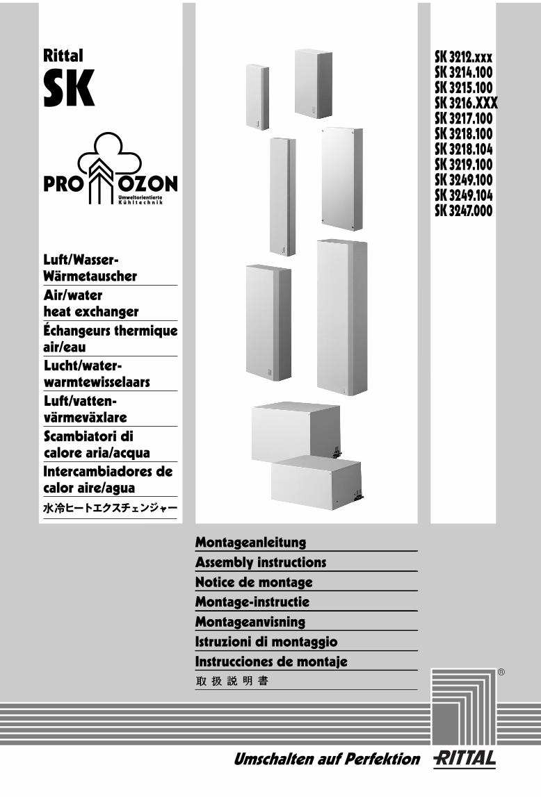
Rittal SK Umweltorientierte Kühltechnik Montageanleitung Assembly instructions Notice de montage Montage-instructie Montageanvisning Istruzioni di montaggio Instrucciones de montaje SK 3212.xxx SK 3214.100 SK 3215.100 SK 3216.XXX SK 3217.100 SK 3218.100 SK 3218.104 SK 3219.100 SK 3249.100 SK 3249.104 SK 3247.000 Umschalten auf Perfektion Luft/Wasser- Wärmetauscher Air/water heat exchanger Échangeurs thermique air/eau Lucht/water- warmtewisselaars Luft/vatten- värmeväxlare Scambiatori di calore aria/acqua Intercambiadores de calor aire/agua

Welcome message from author
This document is posted to help you gain knowledge. Please leave a comment to let me know what you think about it! Share it to your friends and learn new things together.
Transcript
Rittal
SK
UmweltorientierteK ü h l t e c h n i k
MontageanleitungAssembly instructionsNotice de montageMontage-instructieMontageanvisningIstruzioni di montaggioInstrucciones de montaje
SK 3212.xxxSK 3214.100SK 3215.100SK 3216.XXXSK 3217.100SK 3218.100SK 3218.104SK 3219.100SK 3249.100SK 3249.104SK 3247.000
Umschalten auf Perfektion
Luft/Wasser-WärmetauscherAir/waterheat exchangerÉchangeurs thermiqueair/eauLucht/water-warmtewisselaarsLuft/vatten-värmeväxlareScambiatori di calore aria/acquaIntercambiadores decalor aire/agua


2
Deutsch
4. Elektrischer Anschluß
Die Anschlußspannung und -frequenz muß den auf dem Typenschild angegebenen Nennwerten entsprechen. Das Gerät muß über eine Trennvor-richtung an das Netz angeschlossen werden, die mindestens 3 mm Kontaktöffnung im ausgeschal-teten Zustand gewährleistet. Dem Gerät darf ein-speisungsseitig keine zusätzliche Temperatur-regelung vorgeschaltet werden. Als Leitungs-schutz ist die auf dem Typenschild angegebene Vorsicherung vorzusehen. Bei der Installation geltende Vorschriften beachten!
Der Netzanschluß erfolgt an der Anschluß-klemmleiste (siehe Abb. auf Seite 22).
5. Kühlwasseranschluß
Den Kühlwasseranschluß mit druckfesten elasti-schen Schläuchen ausführen und mit Schellen sichern.
(Fließrichtung beachten und auf Dichtheit prüfen!)
Den Wasserkreislauf vor Verschmutzungen und Überdruck schützen (max. zul. Betriebsdruck 10 bar).
Bei der Installation geltende Vorschriften beachten!
6. Kühlbetrieb undRegelverhalten
Der Ventilator des Luftkreislaufes arbeitet perma-nent und gewährleistet somit eine gleichmäßige Temperaturverteilung im Schaltschrank. Ein Magnetventil regelt den Kühlwasserdurchfluß ent-sprechend der eingestellten Solltemperatur. Ein-stellbereich + 20 °C bis + 60 °C. Die Änderung der Schaltschrank-Solltemperatur erfolgt
6.1 bei
SK 3214.100 / SK 3215.100 /SK 3216.100 / SK 3217.100 / SK 3218. . . .
am Thermostat auf der Geräterückseite.6.2 bei
SK 3247.000
am Drehknopf des einge-bauten Thermostaten. Dazu die Gerätehaubeentfernen.
6.3 bei
SK 3219.100 / SK 3249. . . .
amPotentiometer P1 der Regelplatine.Dazu Gerätehaube und Platinenabdeckungentfernen.
6.4 SK 3212.xxx hat keine Regelung.
7. Leckage- undTemperaturüberwachung
7.1 Temperaturüberwachung
Bei einem Ansteigen der Schaltschrank-Innen-temperatur um mehr als10 K bei
SK 3247.000 / SK 3214.100 / SK 3215.100 / SK 3216.100 /SK 3217.100 / SK 3218. . . .
7 K bei
SK 3219.100 / SK 3249. . . .
über der Sollwerteinstellung, erfolgt ein Schalten des potentialfreien Wechselkontaktes. Dieser Kontakt ist über ein separates Kabel bei
SK 3247.000
, einen separaten Stecker bei
SK 3219.100 / SK 3249. . . .
nach außen geführt.Bei
SK 3214.100 / SK 3215.100 / SK 3216.100 /SK 3217.100 / SK 3218. . . .
erfolgt der Anschluß des potentialfreien Kontaktes über die Steck-klemmleiste auf der Geräterückseite.
7.2 Leckageüberwachung
(nur SK 3219.100 / SK 3249. . . .)Sollte im
SK 3219.100 / SK 3249. . . .
eine Undich-tigkeit oder ein Rohrbruch im Wasserkreislauf ein-treten, wirda) die Kühlwasserzufuhr durch das Magnetventil
sofort abgesperrt,b) der potentialfreie Wechselkontakt geschaltet
undc) das Gebläse ausgeschaltet.
Inhaltsverzeichnis
1. Anwendung2. Technische Daten3. Montage 4. Elektrischer Anschluß5. Kühlwasseranschluß6. Kühlbetrieb, Regelverhalten7. Leckage- und Temperaturüberwachung8. Wartung9. Lieferumfang und Garantie
10. Hinweise zur Kondensatableitung11. Sicherheitshinweise12. Hinweise zur Wasserqualität13. Ersatzteilliste
1. Anwendung
Luft/Wasser-Wärmetauscher sind entwickelt und konstruiert, um Verlustleistungen aus Schalt-schränken abzuführen bzw. die Schaltschrank-Innenluft zu kühlen und so temperaturempfindli-che Bauteile zu schützen. Besonders geeignet sind Luft/Wasser-Wärmetauscher für den Umge-bungstemperaturbereich von + 40 °C bis + 70 °C, wo vergleichbare Geräte wie Luft/Luft-Wärmetauscher, Schaltschrank-Kühlgeräte oder Filterlüfter systembedingt nicht einsetzbar sind, um Verlustwärme wirksam und wirtschaftlich abzuführen.
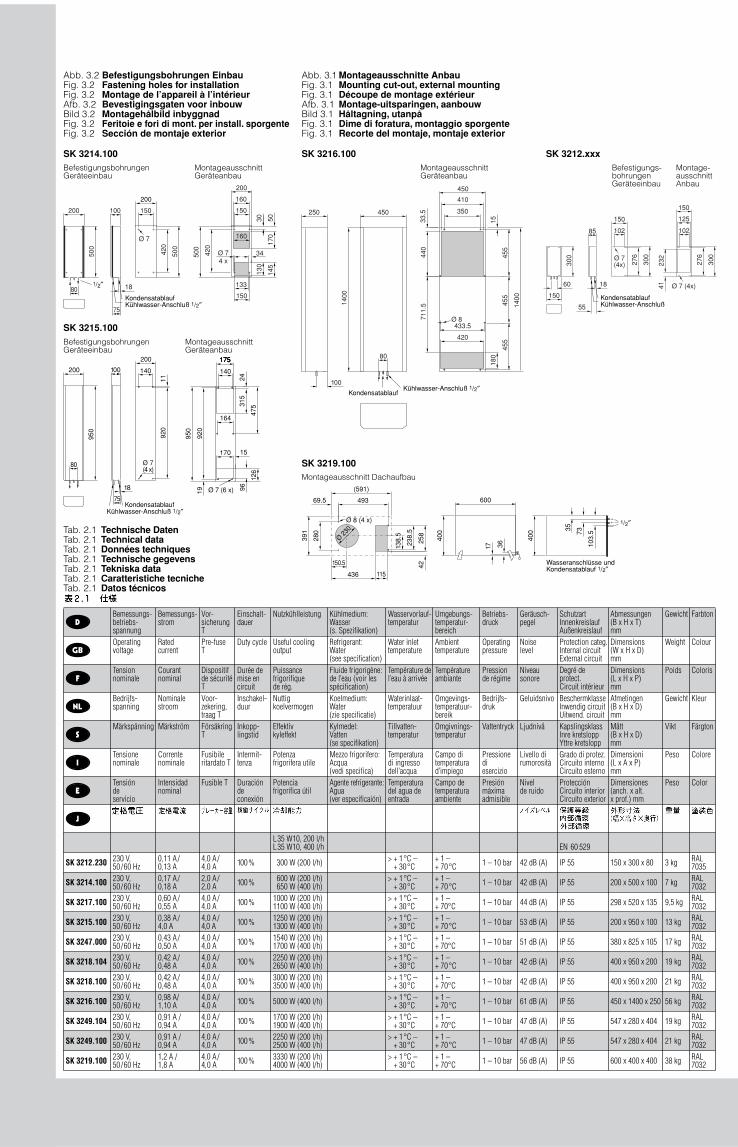
2. Technische Daten
(siehe Tabelle 2.1).
3. Montage
Zum Ausschneiden der Geräteöffnungen beige-fügte Bohrschablone benutzen.
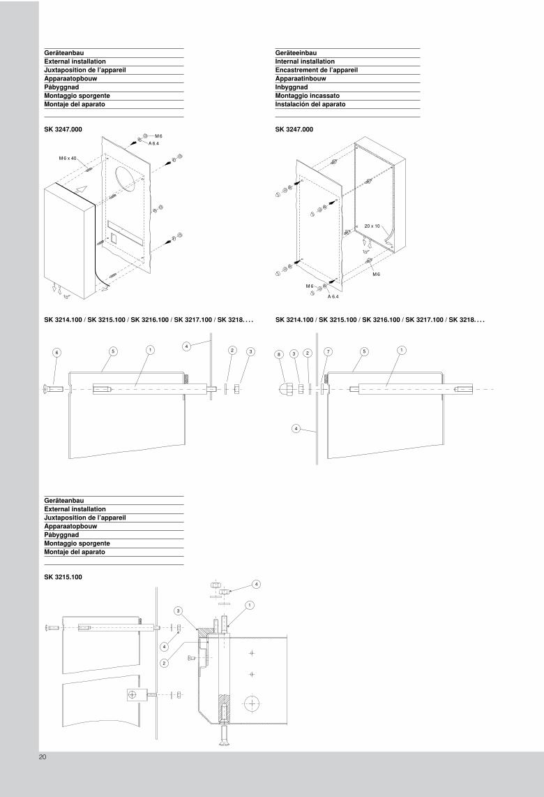
3.1 SK 3247.000
Das Gerät kanna) Am Schaltschrank angebaut werden
s. Abb. Seite 20
b) Im Schaltschrank eingebaut werden
s. Abb. Seite 20
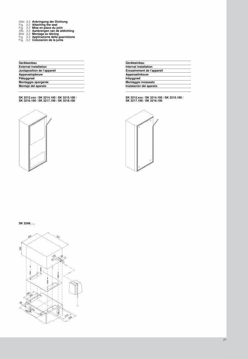
Beiliegende Dichtung ablängen und entspre-chend Abb. 3.2, Seite 21 aufkleben.
3.2 SK 3219.100 / SK 3249. . . .
Das Gerät nach Abb. Seite 21 auf das Schalt-schrankdach montieren. Dazu Abdichtplatte auf das gereinigte Dachblech kleben.
3.3 SK 3214.100 / SK 3215.100 / SK 3216.100 /SK 3217.100 / SK 3218. . . .
Geräteanbau (Abb. Seite 20):
Vier Befestigungsbolzen mit Scheibe undMutter an Montageebene am Schalt-schrank verschrauben. Wärmetauscher auf-schieben und mit vier Schrauben befestigen.
Geräteeinbau (Abb. Seite 19):
Vier Befestigungsbolzen von der Geräterück-seite aus in das Gerät einstecken. Als Montage-hilfe Fixierring auf den Befestigungsbolzen stecken. Gerät mit Scheibe und Mutteran der Montageebene des Schaltschranks von außen verschrauben. Schutzkappe auf Mutter aufstecken.
1 2
3 4
5
6
1
7
2 3
8
8. Wartung
Die Luft/Wasser-Wärmetauscher sind wartungs-frei. Bei verschmutztem Kühlwasser ist der Ein-satz eines Filters notwendig (siehe 12.).Funktion der Kondensatablaufeinrichtung regel-mäßig kontrollieren.
9. Lieferumfang und Garantie
9.1 SK 3247.000 / SK 3214.100 / SK 3215.100 / SK 3216.100 / SK 3217.100 / SK 3218. . . .
1 Luft/Wasser-Wärmetauscher, anschlußfertig1 Dichtband 4 Befestigungsbolzen
(Geräteeinbau SK 3247.000)4 Gewindestifte M6 x 30 (Geräteeinbau)4 Senkschrauben M6*4 Fixierringe*4 Muttern M64 Scheiben A 6,44 Schutzkappen1 Montage- und Betriebsanleitung1 Bohrschablone* nur bei SK 3214.100 / SK 3215.100 /
SK 3216.100 / SK 3217.100 / SK 3218. . . .anstelle der Gewindestifte.
9.2 SK 3219.100 / SK 3249. . . .
1 Luft/Wasser-Wärmetauscher, anschlußfertig1 Abdichtplatte4 Doppelgewindebolzen4 Muttern M64 Fächerscheiben J 6,41 Montage- und Betriebsanleitung1 Bohrschablone1 Winkel-Schlauchverbinder1 Einschraubstutzen2 Anschlußstecker1 Kranöse (nur SK 3219.100)
Garantie:
Auf dieses Gerät gewähren wir 1 Jahr Garantie bei fachgerechter Anwendung vom Tage der Lieferung an. Innerhalb dieses Zeitraumes wird das eingeschickte Gerät im Werk kostenlos repariert oder ausgetauscht. Das Gerät ist aus-schließlich zum Kühlen von Schaltschränken zu verwenden. Bei unsachgemäßer Anwendung oder Anschließung erlischt die Gewährleistung des Herstellers. Für die in solchem Fall entstande-nen Schäden wird nicht gehaftet.

1/2 ″
3
10. Hinweise zur Kondensatableitung
Auf dem Rohrstutzen
1
/
2
″
, der aus dem Gerät herausragt, ist ein Ablaufschlauch aufzustecken, um anfallendes Kondenswasser abzuleiten.Bei
SK 3219.100 / SK 3249. . . .
ist der Ablauf-schlauch mit Winkel-Schlauchverbinder zu verbin-den (nicht knicken!) und direkt nach unten zu führen, damit ein Rückstau und Überlauf des Kondensats im Geräteinneren vermieden wird.
Abb. 10.1
KondensatablaufSK 3219.100 / SK 3249. . . .
Um einen sicheren Kondensatablauf zu gewähr-leisten sind folgende Punkte zu beachten:
�
Ablaufschlauch knickfrei verlegen!
�
Schlauchquerschnitt nicht verkleinern!
�
Ablaufschlauch nur mit Gefälle verlegen!
Um eine erhöhte Kondensatentwicklung zu ver-meiden, und im Sinne der Energieeinsparung sollte die Kühlwassertemperatur der notwendigen Kühlleistung angepaßt werden (siehe Leistungs-diagramme).
11. Sicherheitshinweise
�
Bei Geräteeinbau muß der Kondensatablauf aus dem Schaltschrank geführt werden!
�
Um einen Frostschaden zu vermeiden darf an keiner Stelle des kompletten Wasserkeislaufs die minimal zulässige Wasservorlauftempera-tur von + 1 °C unterschritten werden!
�
Bei Zugabe von Frostschutzmittel ist unbedingtdie Einwilligung des Herstellers einzuholen!
�
Bei Lagerung und Transport unterhalb des Gefrierpunktes ist der Wasserkreislauf mit Druckluft komplett zu entleeren!
�
Thermostat nur so niedrig wie nötig einstellen, da Unterschreitung des Taupunktes mit sinken-der Wasservorlauftemperatur (Kondensatbil-dung)!
�
Allseitige Abdichtung des Schaltschrankes(IP 54), insbesondere der Kabeleinführung (Kondensatbildung)!
Verunreinigung des Wassers Verfahren
mechanische Verunreinigung
Filterung von Wasser über– Siebfilter– Kiesfilter– Patronenfilter– Anschwemmfilter
zu hohe Härte Enthärtung des Wassers durch Ionenaustauschmäßiger Gehalt an mechanischen Verunreinigungen und Härtebildnern
Impfung des Wasses mit Stabilisatoren bzw. Dispergiermitteln
mäßiger Gehalt an chemischen Verunreinigungen
Impfung des Wassers mit Passivatoren und/oder Inhibitoren
biologische VerunreinigungenSchleimbakterien und Algen Impfung des Wassers mit Bioziden
Im Interesse des auslegungsgerechten Betriebes einer Rückkühleinrichtung, die auf mindestens einer Seite mit Wasser betrieben wird, sollte die Beschaffenheit des verwendeten Zusatz- bzw.
Hydrologische Daten
SK 3212.xxx / SK 3247.000 / SK 3219.100 / SK 3249.100 / SK 3214.100 / SK 3215.100 / SK 3216.100 / SK 3217.100 / SK 3218.100
SK 3218.104
1)
SK 3249.104
1)
pH-Wert 7 – 8,5 6 – 9Karbonsäure > 3 < 8 °dH 1 – 12 °dHfreie Kohlensäure 8 – 15 mg/dm
3
1 – 100 mg/dm
3
zugehörige Kohlensäure 8 – 15 mg/dm
3
freiaggressive Kohlensäure 0 mg/dm
3
0 – 400 mg/dm
3
Sulfide frei freiSauerstoff < 10 mg/dm
3
< 10 mg/dm
3
Chlorid-Ionen < 50 mg/dm
3
< 200 mg/dm
3
Sulfat-Ionen < 250 mg/dm
3
< 500 mg/dm
3
Nitrate und Nitrite < 10 mg/dm
3
< 100 mg/dm
3
CSB < 7 mg/dm
3
< 40 mg/dm
3
Ammoniak < 5 mg/dm
3
< 20 mg/dm
3
Eisen < 0,2 mg/dm
3
freiMangan < 0,2 mg/dm
3
freiLeitfähigkeit < 2200 µS/cm < 4000 µS/cmAbdampfrückstand < 500 mg/dm
3
< 2000 mg/dm
3
Kaliumpermanganat-Verbrauch < 25 mg/dm
3
< 40 mg/dm
3
Schwebstoffe< 3 mg/dm
3
> 3 < 15 mg/dm
3
Teilstromreinigung empfohlen> 15 mg/dm
3
kontinuierliche Reinigung empfohlen
Systemwassers nicht wesentlich von der nach-folgenden Auftstellung hydrologischer Daten abweichen:
1)
Das völlige Ausbleiben von Korrosion unter den Versuchsbedingungen läßt darauf schließen,daß auch deutlich stärker salzhaltige Lösungen mit höherem Korrosionspotential (z.B. Meerwasser)noch toleriert werden können.
13. Ersatzteilliste
(siehe Seite 18)
12. Hinweisezur Wasserqualität
Für einen sicheren Betrieb o. g. Geräte müssen die VGB-Kühlwasserrichtlinien unbedingt einge-halten werden (VGB-R 455 P). Kühlwasser darf keine Wassersteinablagerungen oder lockere Ausscheidungen verursachen; es soll also geringe Härte, insbesondere niedrige Karbonhärte, haben. Besonders bei Rückkühlung im Betrieb soll die Karbonhärte nicht zu hoch lie-gen. Andererseits soll das Wasser aber nicht so weich sein, daß es die Werkstoffe angreift. Bei Rückkühlung des Kühlwassers soll der Salzge-halt durch die Verdunstung großer Wassermen-gen nicht zu hoch ansteigen, da mit steigender Konzentration an gelösten Stoffen die elektrische Leitfähigkeit steigt, das Wasser damit korrosiver wird. Deshalb ist nicht nur stets eine entspre-chende Menge Frischwasser zuzusetzen, son-dern auch ein Teil des angereicherten Wassers herauszunehmen.
Gipshaltiges Wasser ist für Kühlzwecke unge-eignet, da es zur Bildung von Kesselstein neigt, der besonders schwer zu entfernen ist. Kühlwasser soll ferner frei von Eisen und Man-gan sein, da sonst Ablagerungen auftreten, die sich in den Rohren festsetzen und diese ver-stopfen. Organische Stoffe sollen höchstens in geringen Mengen vorhanden sein, da sonst Schlammabscheidungen und mikrobiologische Belastungen eintreten.
12.1 Aufbereitung bzw. Pflege des Wassers in Rückkühlanlagen
Je nach Art der zu kühlenden Einrichtung werden an das Kühlwasser bestimmte Forde-rungen bezüglich seiner Reinheit gestellt. Ent-sprechend seiner Verunreinigung sowie der Größe und Bauweise der Rückkühlanlagen kommt dann ein geeignetes Verfahren zur Auf-bereitung und/oder Pflege des Wassers in Anwendung. Die häufigsten Verunreinigungen und gebräuchlichsten Verfahren für deren Beseitigung in der Industriekühlung sind:
4
English
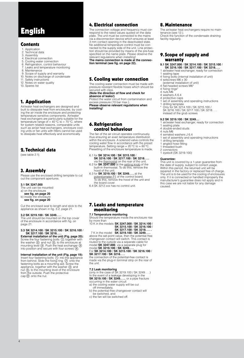
4. Electrical connection
The connection voltage and frequency must cor-respond to the rated values quoted on the data plate. The unit must be connected to the mains via a disconnection device which ensures at least 3 mm contact opening in the deactivated state. No additional temperature control must be con-nected to the supply side of the unit. Line protec-tion should be provided by means of the pre-fuse specified on the name plate. Please observe the relevant regulations when installing!
The mains connection is made at the connec-tion terminal (see fig. on page 22).
5. Cooling water connection
The cooling water connection must be made with pressure resistant flexible hoses which should be secured with clips.
(Note the direction of flow and check for absence of leaks!)
Protect the water circuit from contamination and excess pressure (10 bar max.).
Please observe relevant regulations when installing!
6. Refrigerationcontrol behaviour
The fan of the air circuit operates continuously, thus ensuring an even temperature distribution within the enclosure. A solenoid valve controls the cooling water flow in accordance with the preset temperature. Setting range + 20 °C to + 60 °C. Presetting of the enclosure temperature is made,
6.1 for
SK 3214.100 / SK 3215.100 /SK 3216.100 / SK 3217.100 / SK 3218. . . .
via the thermostat on the rear of the unit.6.2 for
SK 3247.000
at the setting knob of thebuilt-in thermostat. To do this, remove thehood of the unit.
6.3 for
SK 3219.100 / SK 3249. . . .
at thepotentiometer P1 of the control board.To do this, remove the hood of the unit andthe board cover.
6.4 SK 3212.xxx has no control unit.
7. Leaks and temperaturemonitoring
7.1 Temperature monitoring
Should the temperature inside the enclosure rise by more than10 K in the models
SK 3247.000 / SK 3214.100 / SK 3215.100 / SK 3216.100 /SK 3217.100 / SK 3218. . . . .
7 K in the model
SK 3219.100 / SK 3249. . . .
above the set-point value, then the potential-free changeover contact will switch. This contact is routed to the outside via a separate cable for model
SK 3247.000
, via a separate plug for model
SK 3219.100 / SK 3249. . . .
For
SK 3214.100 / SK 3215.100 / SK 3216.100 /SK 3217.100 / SK 3218. . . .
the connection of the potential-free contact is made via the plug-in terminal strip on the rear of the unit.
7.2 Leak monitoring
(only in the case of SK 3219.100 / SK 3249. . . .)In the event of a leakage developing in the
SK 3219.100 / SK 3249. . . .
, or a pipe fracture occurring in the water circuita) the cooling water supply will be cut
off immediately,b) the potential-free changeover contact will
be switched, andc) the fan will be switched off.
8. Maintenance
The air/water heat exchangers require no main-tenance (see 12.).Check the function of the condensate draining facility regularly.
9. Scope of supply andwarranty
9.1 SK 3247.000 / SK 3214.100 / SK 3215.100 / SK 3216.100 / SK 3217.100 / SK 3218. . . .
1 air/water heat exchanger, ready for connection1 sealing tape4 fixing bolts (internal installation of unit)4 setscrews M6 x 30
(external installation of unit)4 flat-headed screws M6*4 fixing rings*4 nuts M64 washers A 6.44 protective caps1 set of assembly and operating instructions1 drilling template* Only for SK 3214.100 / SK 3215.100 /
SK 3216.100 / SK 3217.100 / SK 3218. . . .instead of the grub screws
9.2 SK 3219.100 / SK 3249...
1 air/water heat exchanger, ready for connection1 sealing plate4 double-ended studs4 nuts M64 serrated washers J 6.41 set of assembly and operating instructions1 drilling template1 angled hose fitting1 threaded bush2 connectors1 eyebolt (SK 3219.100)
Guarantee:
This unit is covered by a 1-year guarantee from the date of supply, subject to correct usage. Within this period, the returned unit will be repaired in the factory or replaced free of charge.The unit is to be used for the cooling of enclosures only. If it is connected or handled improperly the manufacturer’s guarantee does not apply and in this case we are not liable for any damage caused.
Contents
1. Application2. Technical data3. Assembly4. Electrical connection5. Cooling water connection6. Refrigeration, control behaviour7. Leaks and temperature monitoring8. Maintenance9. Scope of supply and warranty
10. Notes on discharge of condensate11. Safety instructions12. Notes on water quality13. Spares list
1. Application
Air/water heat exchangers are designed and built to dissipate heat from enclosures, by cool-ing the air inside the enclosure and protecting temperature sensitive components. Air/water heat exchangers are particularly suitable for the temperature range of + 40 °C to + 70 °C, where for system related reasons, comparable units such as air/air heat exchangers, enclosure cool-ing units or fan units with filters cannot be used to dissipate heat effectively and economically.
2. Technical data
(see table 2.1).
3. Assembly
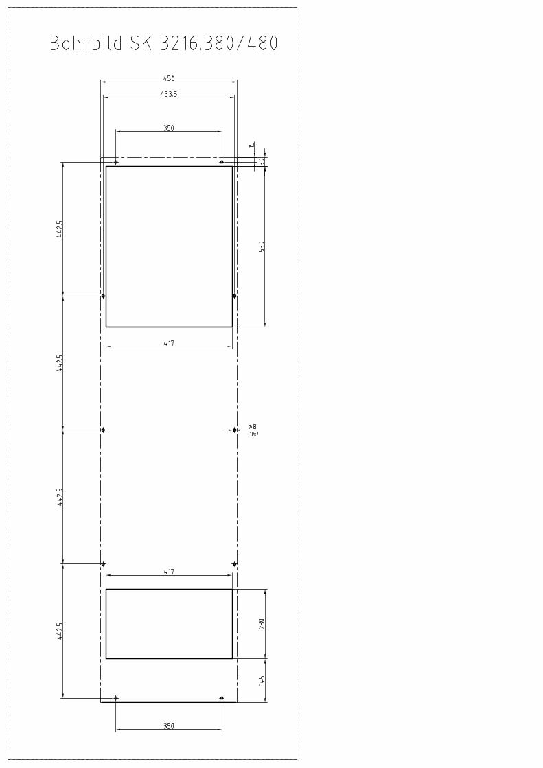
Please use the enclosed drilling template to cut out the component apertures.
3.1 SK 3247.000
The unit can be mounteda) on the enclosure
see fig. on page 20
b) inside the enclosure
see fig. on page 20
Cut the enclosed seal to length and stick to the appliance as shown in fig. 3.2, page 21.
3.2 SK 3219.100 / SK 3249. . . .
The unit should be mounted on the top cover of the enclosure in accordance with fig. on page 21.
3.3 SK 3214.100 / SK 3215.100 / SK 3216.100 /SK 3217.100 / SK 3218. . . .
External installation of the unit (Fig. page 20):
Screw the four fastening bolts , together with the washer and nut , to the enclosure at mounting level . Push the heat exchangerinto position and secure with four screws .
Internal installation of the unit (Fig. page 19):
Insert four fastening bolts into the appliance from behind. Slide the fixing ring onto the fastening bolts as a mounting aid. Screw the appliance, together with the washer and nut , to the mounting level of the enclosure from the outside. Push the protective cap onto the nut.
1
2 3
4 5
6
1
7
2
3
8
1/2 ″
5
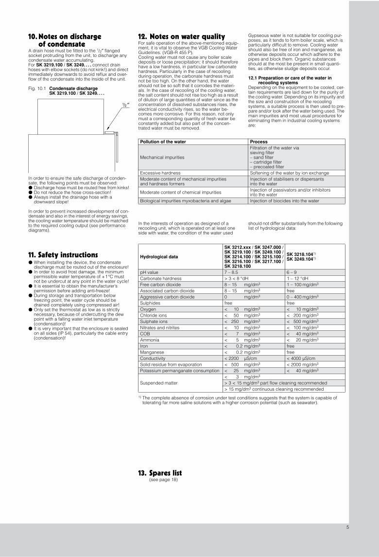
10. Notes on dischargeof condensate
A drain hose must be fitted to the
1
/
2
″
flangedsocket protruding from the unit, to discharge any condensate water accumulating.For
SK 3219.100 / SK 3249. . . .
connect drain hoses with elbow sockets (do not kink!) and direct immediately downwards to avoid reflux and over-flow of the condensate into the inside of the unit.
Fig. 10.1
Condensate dischargeSK 3219.100 / SK 3249. . . .
In order to ensure the safe discharge of conden-sate, the following points must be observed:
�
Discharge hose must be routed free from kinks!
�
Do not reduce the hose cross-section!
�
Always install the drainage hose with a downward slope!
In order to prevent increased development of con-densate and also in the interest of energy savings, the cooling water temperature should be matched to the required cooling output (see performance diagrams).
11. Safety instructions
�
When installing the device, the condensate discharge must be routed out of the enclosure!
�
In order to avoid frost damage, the minimum permissible water temperature of +1°C must not be undercut at any point in the water cycle!
�
It is essential to obtain the manufacturer’s permission before adding anti-freeze!
�
During storage and transportation below freezing point, the water cycle should be drained completely using compressed air!
�
Only set the thermostat as low as is strictly necessary, because of undercutting the dew point with a falling water inlet temperature (condensation)!
�
It is very important that the enclosure is sealed on all sides (IP 54), particularly the cable entry (condensation)!
12. Notes on water quality
For safe operation of the above-mentioned equip-ment, it is vital to observe the VGB Cooling Water Guidelines. (VGB-R 455 P). Cooling water must not cause any boiler scale deposits or loose precipitation; it should therefore have a low hardness, in particular low carbonate hardness. Particularly in the case of recooling during operation, the carbonate hardness must not be too high. On the other hand, the water should not be so soft that it corrodes the materi-als. In the case of recooling of the cooling water, the salt content should not rise too high as a result of dilution of large quantities of water since as the concentration of dissolved substances rises, the electrical conductivity rises, so the water be-comes more corrosive. For this reason, not only must a corresponding quantity of fresh water be constantly added but also part of the concen-trated water must be removed.
Gypseous water is not suitable for cooling pur-poses, as it tends to form boiler scale, which is particularly difficult to remove. Cooling water should also be free of iron and manganese, as otherwise deposits occur which adhere to the pipes and block them. Organic substances should at the most be present in small quanti-ties, as otherwise sludge deposits occur.
12.1 Preparation or care of the water inrecooling systems
Depending on the equipment to be cooled, cer-tain requirements are laid down for the purity of the cooling water. Depending on its impurity and the size and construction of the recooling systems, a suitable process is then used to pre-pare and/or look after the water being used. The main impurities and most usual procedures for eliminating them in industrial cooling systems are:
Pollution of the water Process
Mechanical impurities
Filtration of the water viasieving filter– sand filter– cartridge filter– precoated filter
Excessive hardness Softening of the water by ion exchangeModerate content of mechanical impuritiesand hardness formers
Injection of stabilisers or dispersantsinto the water
Moderate content of chemical impurities Injection of passivators and/or inhibitorsinto the water
Biological impurities myxobacteria and algae Injection of biocides into the water
In the interests of operation as designed of a recooling unit, which is operated on at least one side with water, the condition of the water used
Hydrological data
SK 3212.xxx / SK 3247.000 / SK 3219.100 / SK 3249.100 / SK 3214.100 / SK 3215.100 / SK 3216.100 / SK 3217.100 / SK 3218.100
SK 3218.104
1)
SK 3249.104
1)
pH value 7 – 8.5 6 – 9Carbonate hardness > 3 < 8 °dH 1 – 12 °dHFree carbon dioxide 8 – 15 mg/dm
3
1 – 100 mg/dm
3
Associated carbon dioxide 8 – 15 mg/dm
3
freeAggressive carbon dioxide 0 mg/dm
3
0 – 400 mg/dm
3
Sulphides free freeOxygen < 10 mg/dm
3
< 10 mg/dm
3
Chloride ions < 50 mg/dm
3
< 200 mg/dm
3
Sulphate ions < 250 mg/dm
3
< 500 mg/dm
3
Nitrates and nitrites < 10 mg/dm
3
< 100 mg/dm
3
COB < 7 mg/dm
3
< 40 mg/dm
3
Ammonia < 5 mg/dm
3
< 20 mg/dm
3
Iron < 0.2 mg/dm
3
freeManganese < 0.2 mg/dm
3
freeConductivity < 2200 µS/cm < 4000 µS/cmSolid residue from evaporation < 500 mg/dm
3
< 2000 mg/dm
3
Potassium permanganate consumption < 25 mg/dm
3
< 40 mg/dm
3
Suspended matter< 3 mg/dm
3
> 3 < 15 mg/dm
3
part flow cleaning recommended> 15 mg/dm
3
continuous cleaning recommended
should not differ substantially from the following list of hydrological data:
1)
The complete absence of corrosion under test conditions suggests that the system is capable of tolerating far more saline solutions with a higher corrosion potential (such as seawater).
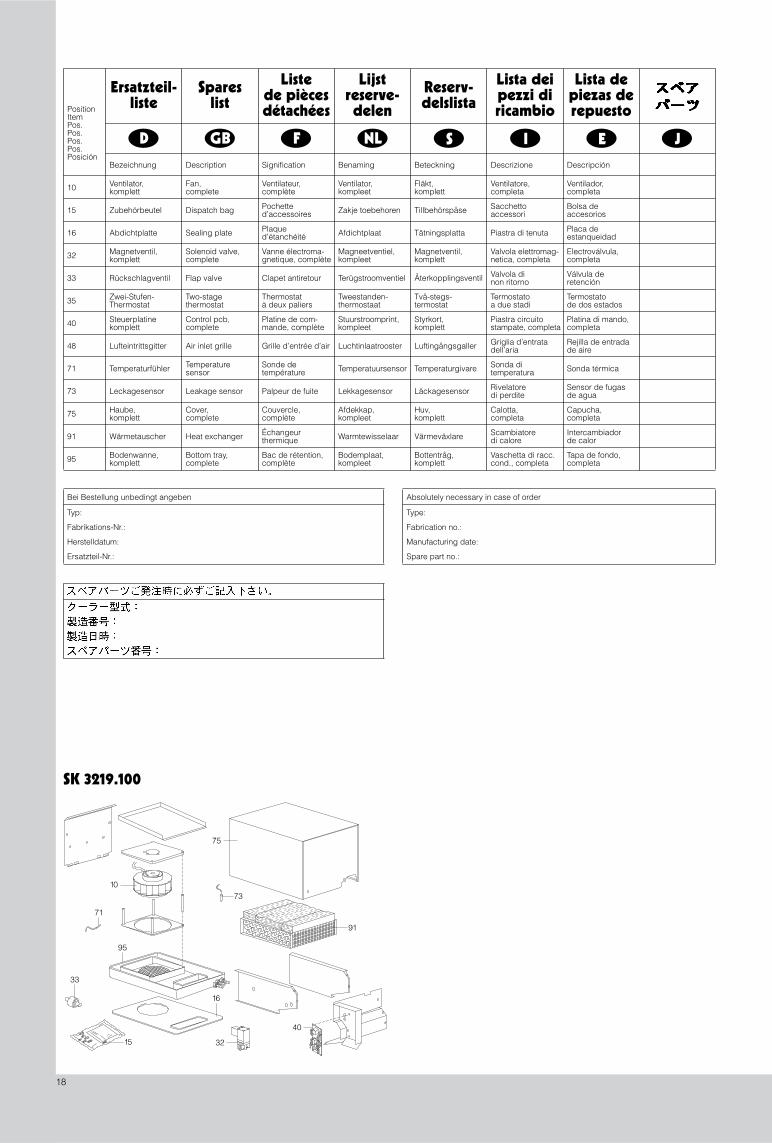
13. Spares list
(see page 18)
80
500
200
420
200
500
150
Ø 7
18
75
100
1/2″
420
500
170
5030
133
150
150
160
200
130
145
160
34Ø 74 x
250 450
100
1400
80
450
350
410
1533.5
440
711.
5
180
455
455
1400
455
433.5Ø 8
420
Ø 7(4 x)
200
140100
18
80
200
75
1/2″
103.
5
400 35 73
3617
600
400
950
1192
0
Ø 230
238.
5
138.
5
258
42
493
(591)
69.5
150.5
391
280
436 115
Ø 8 (4 x)
300
150
60
85
18
55
300
276
232
41
150
125
102
300
276
102
150
Ø 7(4x)
Ø 7 (4x)
Tab. 2.1
Technische Daten
Tab. 2.1
Technical data
Tab. 2.1
Données techniques
Tab. 2.1
Technische gegevens
Tab. 2.1
Tekniska data
Tab. 2.1
Caratteristiche tecniche
Tab. 2.1
Datos técnicos
Abb. 3.2
Befestigungsbohrungen Einbau
Fig. 3.2
Fastening holes for installation
Fig. 3.2
Montage de l’appareil à l’intérieur
Afb. 3.2
Bevestigingsgaten voor inbouw
Bild 3.2
Montagehålbild inbyggnad
Fig. 3.2
Feritoie e fori di mont. per install. sporgente
Fig. 3.2
Sección de montaje exterior
Abb. 3.1
Montageausschnitte Anbau
Fig. 3.1
Mounting cut-out, external mounting
Fig. 3.1
Découpe de montage extérieur
Afb. 3.1
Montage-uitsparingen, aanbouw
Bild 3.1
Håltagning, utanpå
Fig. 3.1
Dime di foratura, montaggio sporgente
Fig. 3.1
Recorte del montaje, montaje exterior
Bemessungs-betriebs-spannung
Bemessungs-strom
Vor-sicherung T
Einschalt-dauer
Nutzkühlleistung Kühlmedium:Wasser(s. Spezifikation)
Wasservorlauf-temperatur
Umgebungs-temperatur-bereich
Betriebs-druck
Geräusch-pegel
SchutzartInnenkreislaufAußenkreislauf
Abmessungen(B x H x T)mm
Gewicht Farbton
Operatingvoltage
Ratedcurrent
Pre-fuseT
Duty cycle Useful coolingoutput
Refrigerant:Water(see specification)
Water inlet temperature
Ambient temperature
Operating pressure
Noiselevel
Protection categ.Internal circuitExternal circuit
Dimensions(W x H x D)mm
Weight Colour
Tension nominale
Courant nominal
Dispositif de sécurité T
Durée de mise encircuit
Puissance frigorifique de rég.
Fluide frigorigène:de l’eau (voir les spécification)
Température de l’eau à arrivée
Températureambiante
Pressionde régime
Niveausonore
Degré de protect.Circuit intérieur
Dimensions(L x H x P)mm
Poids Coloris
Bedrijfs-spanning
Nominale stroom
Voor-zekering, traag T
Inschakel-duur
Nuttig koelvermogen
Koelmedium:Water(zie specificatie)
Waterinlaat-temperatuur
Omgevings-temperatuur-bereik
Bedrijfs-druk
Geluidsnivo BeschermklasseInwendig circuitUitwend. circuit
Afmetingen (B x H x D)mm
Gewicht Kleur
Märkspänning Märkström Försäkring T
Inkopp-lingstid
Effektiv kyleffekt
Kylmedel:Vatten(se specifikation)
Tillvatten-temperatur
Omgivnings-temperatur
Vattentryck Ljudnivå KapslingsklassInre kretsloppYttre kretslopp
Mått(B x H x D)mm
Vikt Färgton
Tensione nominale
Correntenominale
Fusibile ritardato T
Intermit-tenza
Potenza frigorifera utile
Mezzo frigorifero:Acqua(vedi specifica)
Temperaturadi ingresso dell’acqua
Campo di temperatura d’impiego
Pressione di esercizio
Livello di rumorosità
Grado di protez.Circuito internoCircuito esterno
Dimensioni(L x A x P)mm
Peso Colore
Tensión deservicio
Intensidad nominal
Fusible T Duración deconexión
Potencia frigorífica útil
Agente refrigerante:Agua(ver especificaión)
Temperaturadel agua de entrada
Campo detemperatura ambiente
Presión máxima admisible
Nivelde ruido
ProtecciónCircuito interiorCircuito exterior
Dimensiones(anch. x alt.x prof.) mm
Peso Color
L35 W10, 200 l/hL35 W10, 400 l/h EN 60 529
SK 3212.230
230 V, 50/60 Hz
0,11 A/0,13 A
4,0 A/4,0 A 100% 300 W (200 l/h) > + 1°C –
+ 30°C+ 1 – + 70°C 1 – 10 bar 42 dB (A) IP 55 150 x 300 x 80 3 kg RAL
7035
SK 3214.100
230 V, 50/60 Hz
0,17 A/0,18 A
2,0 A/2,0 A 100% 600 W (200 l/h)
650 W (400 l/h)> + 1°C –
+ 30°C+ 1 – + 70°C 1 – 10 bar 42 dB (A) IP 55 200 x 500 x 100 7 kg RAL
7032
SK 3217.100
230 V, 50/60 Hz
0,60 A/0,55 A
4,0 A/4,0 A 100% 1000 W (200 l/h)
1100 W (400 l/h)> + 1°C –
+ 30°C+ 1 – + 70°C 1 – 10 bar 44 dB (A) IP 55 298 x 520 x 135 9,5 kg RAL
7032
SK 3215.100
230 V, 50/60 Hz
0,38 A/4,0 A
4,0 A/4,0 A 100% 1250 W (200 l/h)
1300 W (400 l/h)> + 1°C –
+ 30°C+ 1 – + 70°C 1 – 10 bar 53 dB (A) IP 55 200 x 950 x 100 13 kg RAL
7032
SK 3247.000
230 V, 50/60 Hz
0,43 A/0,50 A
4,0 A/4,0 A 100% 1540 W (200 l/h)
1700 W (400 l/h) > + 1°C –+ 30°C
+ 1 – + 70°C 1 – 10 bar 51 dB (A) IP 55 380 x 825 x 105 17 kg RAL
7032
SK 3218.104
230 V, 50/60 Hz
0,42 A/0,48 A
4,0 A/ 4,0 A 100% 2250 W (200 l/h)
2650 W (400 l/h)> + 1°C –
+ 30°C+ 1 – + 70°C 1 – 10 bar 42 dB (A) IP 55 400 x 950 x 200 19 kg RAL
7032
SK 3218.100
230 V, 50/60 Hz
0,42 A/0,48 A
4,0 A/4, 0 A 100% 3000 W (200 l/h)
3500 W (400 l/h)> + 1°C –
+ 30°C+ 1 – + 70°C 1 – 10 bar 42 dB (A) IP 55 400 x 950 x 200 21 kg RAL
7032
SK 3216.100
230 V, 50/60 Hz
0,98 A/1,10 A
4,0 A/ 4,0 A 100% 5000 W (400 l/h) > + 1°C –
+ 30°C+ 1 – + 70°C 1 – 10 bar 61 dB (A) IP 55 450 x 1400 x 250 56 kg RAL
7032
SK 3249.104
230 V, 50/60 Hz
0,91 A /0,94 A
4,0 A/4,0 A 100% 1700 W (200 l/h)
1900 W (400 l/h)> + 1°C –
+ 30°C+ 1 – + 70°C 1 – 10 bar 47 dB (A) IP 55 547 x 280 x 404 19 kg RAL
7032
SK 3249.100
230 V, 50/60 Hz
0,91 A /0,94 A
4,0 A/ 4,0 A 100% 2250 W (200 l/h)
2500 W (400 l/h)> + 1°C –
+ 30°C+ 1 – + 70°C 1 – 10 bar 47 dB (A) IP 55 547 x 280 x 404 21 kg RAL
7032
SK 3219.100
230 V, 50/60 Hz
1,2 A /1,8 A
4,0 A/4, 0 A 100% 3330 W (200 l/h)
4000 W (400 l/h)> + 1°C –
+ 30°C+ 1 – + 70°C 1 – 10 bar 56 dB (A) IP 55 600 x 400 x 400 38 kg RAL
7032
D
GB
F
NL
S
I
E
J
SK 3214.100
SK 3215.100
SK 3219.100
SK 3216.100
KondensatablaufKühlwasser-Anschluß
1
/
2
″
KondensatablaufKühlwasser-Anschluß
1
/
2
″
KondensatablaufKühlwasser-Anschluß
1
/
2
″
Wasseranschlüsse undKondensatablauf
1
/
2
″
BefestigungsbohrungenGeräteeinbau
MontageausschnittGeräteanbau
MontageausschnittGeräteanbau
BefestigungsbohrungenGeräteeinbau
Montageausschnitt Dachaufbau
175175175
170 15
47531
524
126
961992
0
950
164
140
Ø 7 (6 x)
MontageausschnittGeräteanbau
SK 3212.xxx
KondensatablaufKühlwasser-Anschluß
Befestigungs-bohrungenGeräteeinbau
Montage-ausschnittAnbau
Ø 8 (4 x)
53
264
280
397
95 310 8723 23
400
210
226
(538)
280
404
547
135298
520
520
475
Ø 7
298
240
520
475
298
272
240
230
3312
712
0
208
Ø 7
400
950
904
340
340
6028
046
311
2
280
Ø 7
400 200
950
400
950
280
904
Ø 7
Kühlwasseranschluß
Scarico della condensaKondensavloppCondensafvoer
Escoulement de l’eaude condensation
Condensate dischargeKondensatablauf
Eliminación del aguade condensación
Cooling water connectionRaccordement d’eau de refroidissementAansluiten koelwaterKylvattenanslutningAllacciamento idricoConexión a la acometida de agua
300
128
85
470
230
320
40
75
750
825
25
40
380
Ø 8
105
45
85
380350
380
Ø 8
Ø 13 1/ ″2
825
765
825
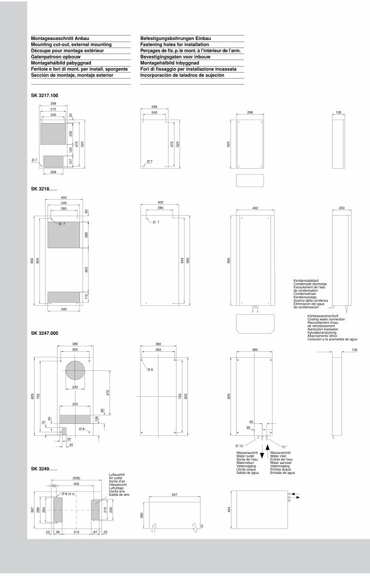
Montageausschnitt AnbauMounting cut-out, external mountingDécoupe pour montage extérieurGatenpatroon opbouwMontagehålbild påbyggnadFeritoie e fori di mont. per install. sporgenteSección de montaje, montaje exterior
Befestigungsbohrungen EinbauFastening holes for installationPerçages de fix.p. le mont. à l’intérieur de l’arm.Bevestigingsgaten voor inbouwMontagehålbild inbyggnadFori di fissaggio per installazione incassataIncorporación de taladros de sujeción
SK 3218. . . .
SK 3247.000
SK 3249. . . .
WassereintrittWater inletEntrée de l’eauWater aanvoerVatteningångEntrata acquaEntrada de agua
WasseraustrittWater outletSortie de l’eauWaterretourVattenutgångUscita acquaSalida de agua
SK 3217.100
LuftaustrittAir outletSortie d’airInblaasluchtLuftutloppUscita ariaSalida de aire
18
75
73
91
10
95
71
33
15
16
40
32
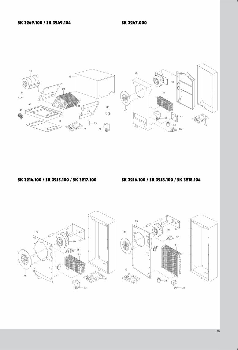
Ersatzteil-liste
Spareslist
Listede pièces détachées
Lijstreserve-delen
Reserv-delslista
Lista dei pezzi di ricambio
Lista de piezas de repuesto
Bezeichnung Description Signification Benaming Beteckning Descrizione Descripción
10 Ventilator,komplett
Fan,complete
Ventilateur,complète
Ventilator,kompleet
Fläkt,komplett
Ventilatore,completa
Ventilador,completa
15 Zubehörbeutel Dispatch bag Pochette d’accessoires Zakje toebehoren Tillbehörspåse Sacchetto
accessoriBolsa de accesorios
16 Abdichtplatte Sealing plate Plaqued’étanchéité Afdichtplaat Tätningsplatta Piastra di tenuta Placa de
estanqueidad
32 Magnetventil,komplett
Solenoid valve,complete
Vanne électroma-gnetique, complète
Magneetventiel,kompleet
Magnetventil,komplett
Valvola elettromag-netica, completa
Electroválvula,completa
33 Rückschlagventil Flap valve Clapet antiretour Terügstroomventiel Återkopplingsventil Valvola di non ritorno
Válvula de retención
35 Zwei-Stufen-Thermostat
Two-stagethermostat
Thermostatà deux paliers
Tweestanden-thermostaat
Två-stegs-termostat
Termostatoa due stadi
Termostatode dos estados
40 Steuerplatinekomplett
Control pcb,complete
Platine de com-mande, complète
Stuurstroomprint, kompleet
Styrkort, komplett
Piastra circuito stampate, completa
Platina di mando,completa
48 Lufteintrittsgitter Air inlet grille Grille d’entrée d’air Luchtinlaatrooster Luftingångsgaller Griglia d’entrata dell’aria
Rejilla de entrada de aire
71 Temperaturfühler Temperature sensor
Sonde de température Temperatuursensor Temperaturgivare Sonda di
temperatura Sonda térmica
73 Leckagesensor Leakage sensor Palpeur de fuite Lekkagesensor Läckagesensor Rivelatore di perdite
Sensor de fugas de agua
75 Haube,komplett
Cover,complete
Couvercle,complète
Afdekkap,kompleet
Huv,komplett
Calotta,completa
Capucha,completa
91 Wärmetauscher Heat exchanger Échangeur thermique Warmtewisselaar Värmeväxlare Scambiatore
di caloreIntercambiadorde calor
95 Bodenwanne,komplett
Bottom tray,complete
Bac de rétention,complète
Bodemplaat,kompleet
Bottentråg,komplett
Vaschetta di racc.cond., completa
Tapa de fondo,completa
D E JGB NL IF S
PositionItemPos.Pos.Pos.Pos.Posición
Bei Bestellung unbedingt angeben
Typ:
Fabrikations-Nr.:
Herstelldatum:
Ersatzteil-Nr.:
Absolutely necessary in case of order
Type:
Fabrication no.:
Manufacturing date:
Spare part no.:
SK 3219.100
19
10
75
91
40
15
71
32
95
1673
33
91
33 15
32
75
10
35
48
32
75
10
35
91
4815
32
33
35
91
48
15
10
75
SK 3249.100 / SK 3249.104 SK 3247.000
SK 3214.100 / SK 3215.100 / SK 3217.100 SK 3216.100 / SK 3218.100 / SK 3218.104
1
4
3
4
2
GeräteanbauExternal installationJuxtaposition de l’appareilApparaatopbouwPåbyggnadMontaggio sporgenteMontaje del aparato
GeräteeinbauInternal installationEncastrement de l’appareilApparaatinbouwInbyggnadMontaggio incassatoInstalación del aparato
M 6 x 40
M 6
A 6.4
1/2″
1/2″
20 x 10
M 6
A 6.4
M 6
SK 3247.000
SK 3214.100 / SK 3215.100 / SK 3216.100 / SK 3217.100 / SK 3218. . . .
SK 3247.000
SK 3214.100 / SK 3215.100 / SK 3216.100 / SK 3217.100 / SK 3218. . . .
GeräteanbauExternal installationJuxtaposition de l’appareilApparaatopbouwPåbyggnadMontaggio sporgenteMontaje del aparato
SK 3215.100
20
6 5 14
2 38 3 2 7 15
4
19
1/2″
547404
280
95
310
87
400
226210
264280
34
72103
GeräteanbauExternal installationJuxtaposition de l’appareilApparaatopbouwPåbyggnadMontaggio sporgenteMontaje del aparato
GeräteeinbauInternal installationEncastrement de l’appareilApparaatinbouwInbyggnadMontaggio incassatoInstalación del aparato
Abb. 3.2
Anbringung der Dichtung
Fig. 3.2
Attaching the seal
Fig. 3.2
Mise en place du joint
Afb. 3.2
Aanbrengen van de afdichting
Bild 3.2
Montage av tätning
Fig. 3.2
Applicazione della guarnizione
Fig. 3.2
Colocación de la junta
SK 3249. . . .
SK 3212.xxx / SK 3214.100 / SK 3215.100 / SK 3216.100 / SK 3217.100 / SK 3218.100
SK 3212.xxx / SK 3214.100 / SK 3215.100 / SK 3217.100 / SK 3218.100
21
N L1
M1~
M1
K3
VE2 VE3MA2 ST1 ST2 ST3 TS1 TS2 LS1 LS2
P1
T i m
ax.
Leck
Leak
Fui
teLe
kkag
eLä
ckag
eP
erdi
taF
ugas
D9 D8A B C CBA
Y1
B2B1
2 1 3
N PE L1
123
PE
PE
g/g 2 1
br
C1
PE 4 5 6
654
T1 T2 S3
12
A1
X10
NetzanschlußMains connectionRaccordement au résauNetaansluitingNätanslutningAllacciamento reteConexión de red
X20X3
Technische Daten siehe TypenschildTechnical data see name plateDonnées techniques voir plaque signalétiqueTechnische gegevens zie typeplaatjeTekniska data se typskyltenCaratteristiche tecniche vedi dati di targaDatos técnicos ver placa de características
X1: X2:X1:
X11
L 1 2 N PE 3 4 5 6
M1~
sw2
sw
bl gn/gb
gn/gb
sw2sw1
sw
sw1 sw2 gn/gb
br
sw1
sw3 sw1sw2
< ϑ14
11
12
31
32
34
F1.2F1.1
Y1M1
C1
➁ ➂
➀
M1~
32
X103
C1
F1.2
Y1
1431
T
34
M1
4 5
X20
X10
L1 N
T
11
F1.1
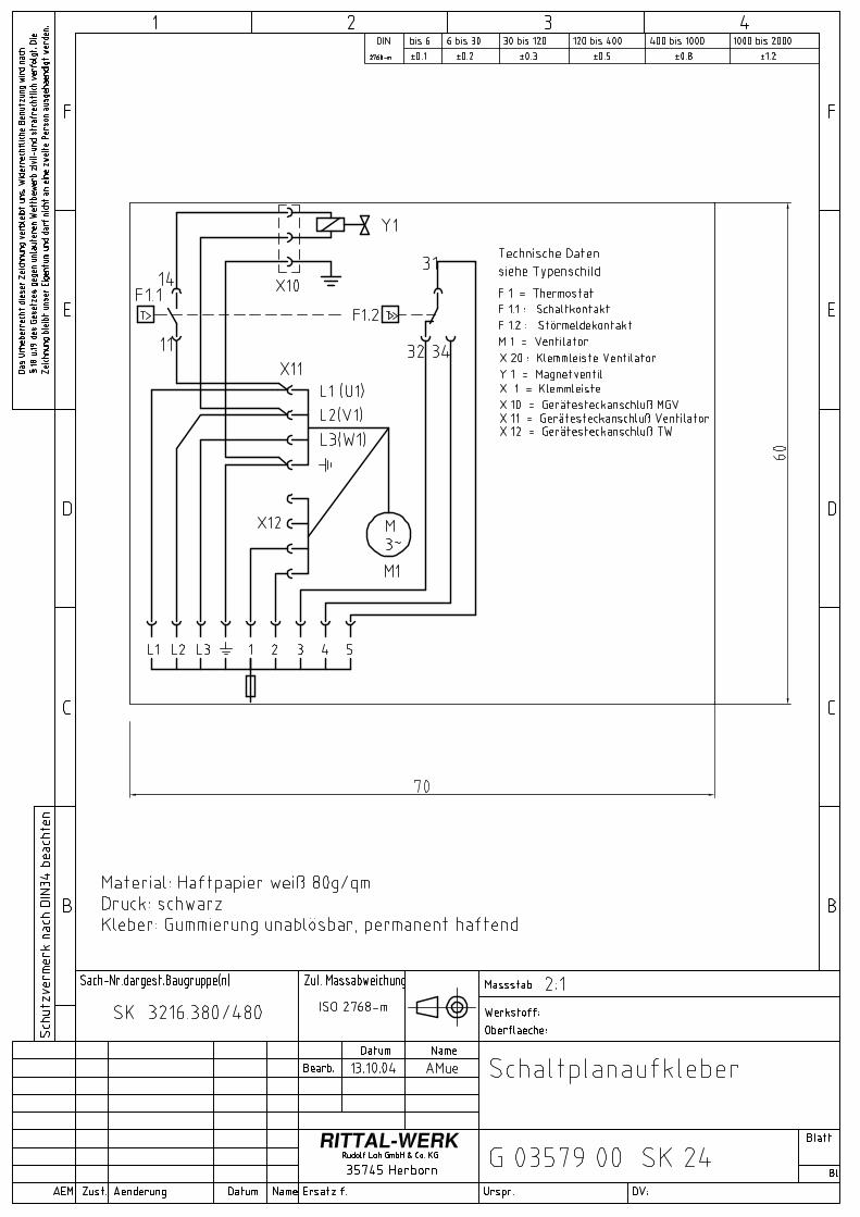
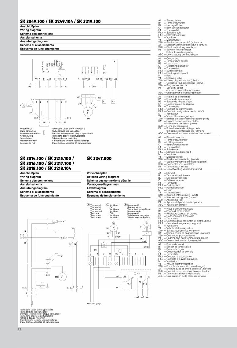
A1 = SteuerplatineB1 = TemperaturfühlerB2 = LeckagefühlerC1 = BetriebskondensatorF1 = ThermostatF1.1 = SchaltkontaktF1.2 = StörmeldekontaktM1 = VentilatorY1 = MagnetventilX10 = Stecker Netzanschluß (schwarz)X11 = Stecker Sammelstörmeldung (braun)X20 = Steckverbindung VentilatorP1 = Sollwert-Potentiometer
= SchrankinnentemperaturABC = Umschaltung der Betriebsart
SK 3249.100 / SK 3249.104 / SK 3219.100
AnschlußplanWiring diagramSchema des connexionsAansluitschemaAnslutningsdiagramSchema di allacciamentoEsquema de funcionamiento
A1 = Control pcbB1 = Temperature sensorB2 = Leak sensorC1 = Operating capacitorF1 = ThermostatF1.1 = Switch contactF1.2 = Fault signal contactM1 = FanY1 = Solenoid valveX10 = Mains plug connector (black)X11 = Collective fault signal plug (brown)X20 = Plug connection fanP1 = Set-point setter,
= enclosure internal temperatureABC = Changeover of operating mode
A1 = Platine de commandeB1 = Sonde de températureB2 = Sonde de niveau d’eauC1 = Condensateur de régimeF1 = ThermostatF1.1 = Contact de commitationF1.2 = Contact de signalisation de défaútM1 = VentilateurY1 = Vanne électromagnétiqueX10 = Bornes de raccordement secteur (noir)X11 = Bornes de raccordement des
= indications de défaut (brun)X20 = Fiche dú ventilateurP1 = Potentiomètre de réglage de la
= température intérieure de l’armoireABC = Commutation du mode de fonctionnement
A1 = StuurstroomprintB1 = TemperatuursensorB2 = LekkagesensorC1 = BedrijfskondensatorF1 = ThermostaatF1.1 = SchakelaarF1.2 = StoringsmelderkontaktM1 = VentilatorY1 = MagneetventielX10 = Stekker netaansluiting (zwart)X11 = Stekker verzamelsfoormelding (bruin)X20 = Connector voor ventilatorP1 = Temperatuur in kastABC = Omschakeling van bedrijfsstand
A1 = StyrkortB1 = TemperaturavkännareB2 = LäckageavkännareC1 = DriftkondensatorF1 = TermostatF1.1 = OmkopplareF1.2 = FelmeddelandeM1 = FläktY1 = MagnetventilX10 = Kontakt nätanslutning (svart)X11 = Kontakt störsignaler (brun)X20 = Anslutning fläktP1 = Apparatskåpets innertemperaturABC = Växling av funktion
A1 = Piastra circuito stampateB1 = Sonda di temperaturaB2 = Rivelatore (sonda) di preditaC1 = Condensatore d’esercizioF1 = TermostatoF1.1 = Contatto degli interruttori di distribuzioneF1.2 = Contatto di segnalazione guastiM1 = VentilatoreY1 = Valvola elettromagneticaX10 = Spina allacciamento rete (nero)X11 = Spina circuito de segnalazione (marrone)X20 = Connettore per ventilatoreP1 = Regolazione della temperatura internaABC = Commutazione del tipo esercizio
A1 = Platina de mandoB1 = Sensor de temperaturaB2 = Sensor de fugasC1 = Condensador de servicioF1 = TermostatoF1.1 = Contacto de conecciónF1.2 = Contacto de aviso de averiaM1 = VentiladorY1 = Válvula electromagnéticaX10 = Enchufe alimentación de red (negro)X11 = Enchufe aviso de avería colectiva (marrón)X20 = Contacto de conección para ventiladorP1 = Temperatura interior del armarioABC = Commutación de la clase de servicio
SK 3247.000
WirkschaltplanDetailed wiring diagramSchéma des connexions détailléVermogensdiagrammenEffektdiagramSchema di allacciamentoEsquema de funcionamiento
➀
ThermostatThermostatThermostatThermostaatTermostatTermostatoTermostato
➁
VentilatorFanVentilateurVentilatorFläktVentilatoreVentilador
➂
MagnetventilSolenoid valveVanne électromagnétiqueMagneetventielMagnetventilValvola elettromagneticaVálvula electromagnética
SK 3214.100 / SK 3215.100 /SK 3216.100 / SK 3217.100 /SK 3218.100 / SK 3218.104
AnschlußplanWiring diagramSchema des connexionsAansluitschemaAnslutningsdiagramSchema di allacciamentoEsquema de funcionamiento
22
Technische Daten siehe TypenschildTechnical data see name plateDonnées techniques voir plaque signalétiqueTechnische gegevens zie typeplaatjeTekniska data se typskyltenCaratteristiche tecniche vedi dati di targaDatos técnicos ver placa de características
23
5500
1000
1500
2000
2500
3000
3500
4000
10 15 20 25 30 35 Ti
QK
.
TW
VW = 400 l/hVW = 200 l/hVW = 100 l/h
.
.
.
35 °C
45 °C
25 °C
5750
1000
1250
1500
1750
2000
2250
2500
2750
10 15 20 25 30 35
Ti
QK
.
TW
VW = 400 l/hVW = 200 l/hVW = 100 l/h
.
.
.
35 °C
45 °C
25 °C
105 15 20 25 30 35
500
1000
1500
2000
2500
40 °C
30 °C
20 °C
50 °C
Ti
QK
.
TW
VW = 200 l/hVW = 150 l/hVW = 100 l/h
.
.
.
5250
10 15 20 25 30
500
750
1000
1250
1500
1750
45 °C
35 °C
25 °C
QK
.
TW
Ti
VW = 400 l/hVW = 200 l/hVW = 100 l/h
.
.
.
5 10 15 20 25 30500
1000
1500
2000
2500
3000
3500
4000
45 °C
35 °C
25 °C
Ti
QK
.
TW
VW = 400 l/hVW = 200 l/hVW = 100 l/h
.
.
.
45°C35°C
25°C
120011001000900800700600500400300200100
5 10 15 20 25 30 35
VW = 400 l/h.
VW = 200 l/h.
QK
.
TW
Ti
2400220020001600140012001000800600400200
5 10 15 20 25 30 35
45°C35°C
25°C
VW = 400 l/h.
VW = 200 l/h.
QK
.
TW
Ti
9000
8000
7000
6000
5000
4000
3000
2000
10005 10 15 20 25 30 35
45°C35°C
25°C
VW = 400 l/h.
VW = 200 l/h.
QK
.
TWTi
25°C
35°C
45°C
9000
8000
7000
6000
5000
4000
3000
2000
10005 10 15 20 25 30 35
VW = 400 l/h.
VW = 200 l/h.
QK
.
TWTi
∆P
V.300 400 500
300
200
100
400
∆P
V.200 300 400
300
200
100
400
∆P
V.200 300 400
300
200
100
400
∆P
V.300 400 500
300
200
100
400
∆P
V.300 400 500
400
300
200
500
∆P
V.400 500 600
500
400
300
600
∆P
V.400 500 600
300
200
100
400
∆P
V.100
400
300
200
500
200 300 400
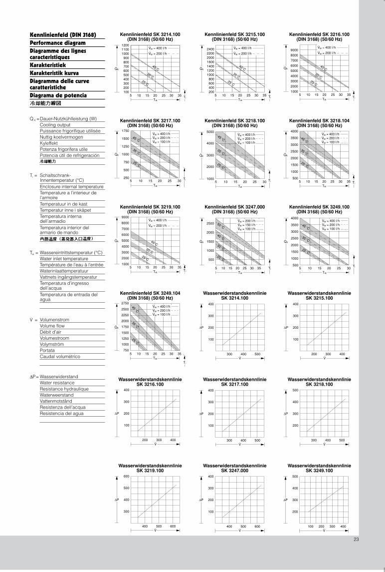
Kennlinienfeld (DIN 3168)Performance diagramDiagramme des lignescaracteristiquesKarakteristiekKarakteristik kurvaDiagramma delle curvecaratteristicheDiagrama de potencia
Dauer-Nutzkühlleistung (W)Cooling outputPuissance frigorifique utiliséeNuttig koelvermogenKyleffektPotenza frigorifera utilePotencia útil de refrigeración
Q· K =
Schaltschrank-Innentemperatur (°C)Enclosure internal temperatureTemperature a l’interieur de l’armoireTemperatuur in de kastTemperatur inne i skåpetTemperatura interna dell’armadioTemperatura interior del armario de mando
Ti =
Wassereintrittstemperatur (°C)Water inlet temperatureTempérature de l’eau à l’entréeWaterinlaattemperatuurVattnets ingångstemperaturTemperatura d’ingresso dell’acquaTemperatura de entrada del agua
Tw =
Kennlinienfeld SK 3218.104(DIN 3168) (50/60 Hz)
Kennlinienfeld SK 3217.100(DIN 3168) (50/60 Hz)
Kennlinienfeld SK 3215.100(DIN 3168) (50/60 Hz)
51000
10 15 20 25 30
2000
3000
4000
5000
35 °C
25 °C
Ti
QK
.
TW
VW = 400 l/hVW = 200 l/hVW = 100 l/h
.
.
.45 °C
VolumenstromVolume flowDébit d’airVolumestroomVolymströmPortataCaudal volumétrico
V.
=
WasserwiderstandWater resistanceResistance hydrauliqueWaterweerstandVattenmotståndResistenza dell’acquaResistencia del agua
∆P=
Kennlinienfeld SK 3214.100(DIN 3168) (50/60 Hz)
Kennlinienfeld SK 3216.100(DIN 3168) (50/60 Hz)
Kennlinienfeld SK 3218.100(DIN 3168) (50/60 Hz)
Kennlinienfeld SK 3219.100(DIN 3168) (50/60 Hz)
Kennlinienfeld SK 3249.104(DIN 3168) (50/60 Hz)
Kennlinienfeld SK 3247.000(DIN 3168) (50/60 Hz)
Kennlinienfeld SK 3249.100(DIN 3168) (50/60 Hz)
WasserwiderstandskennlinieSK 3214.100
WasserwiderstandskennlinieSK 3215.100
WasserwiderstandskennlinieSK 3216.100
WasserwiderstandskennlinieSK 3217.100
WasserwiderstandskennlinieSK 3218.100
WasserwiderstandskennlinieSK 3219.100
WasserwiderstandskennlinieSK 3247.000
WasserwiderstandskennlinieSK 3249.100
Umschalten auf Perfektion
Schaltschrank-SystemeIndustrial EnclosuresSystèmes d’armoires électriquesSchakelkastsystemenApparatskåpssystemSistemi di armadi per quadri di comandoSistemas de armarios de distribución
Elektronik-Aufbau-Systeme ELElectronic Packaging ELSystèmes d’intégration électronique ELElektronica opbouwsystemen ELElektronikuppbyggnad och inkapsling ELSistemi di allestimento per l’elettronica industriale ELSistemas para electrónica EL
Power Distribution SV
IT SolutionsIT-Solutions
Communication Systems CSCommunication Systems CS
System Climate Control SK
Stromverteilung SV
System-Klimatisierung SK
Distribution du courant SVStroomverdeling SVStrömfördelning SVDistribuzione di corrente SVDistribución de corriente SV
Solutions ITIT-SolutionsIT-lösningarSoluzioni per ITSoluciones TI
Solutions Télécom CSOutdoor-behuizingen CSUtomhusskåp CSSoluzioni outdoor CSSistemas para comunicaciones CS
Systèmes de climatisation SKSysteemklimatisering SKSystemklimatisering SKSoluzioni di climatizzazione per quadri di comando SKClimatización de sistemas SK
239 952
Rittal GmbH & Co. KG · Postfach 1662 · D-35726 HerbornTel.: +49(0)2772 505-0 · Fax: +49(0)2772 505-2319 · eMail: [email protected] · www.rittal.de
4. A
ufl.
10/0
4(1
2/98
)
Related Documents