© Monitoring Plan for a Cyclic Steam Stimulation (CSS) Pilot Test in Orinoco Oil Belt, Venezuela Repsol Technology Center (CTR), Madrid PEA 2016 – Aberdeen, Scotland, UK CTR | CSS Pilot Test Monitoring Plan - PEA 2016

Welcome message from author
This document is posted to help you gain knowledge. Please leave a comment to let me know what you think about it! Share it to your friends and learn new things together.
Transcript
©
Monitoring Plan for a Cyclic Steam
Stimulation (CSS) Pilot Test in
Orinoco Oil Belt, Venezuela
Repsol Technology Center (CTR), Madrid
PEA 2016 – Aberdeen, Scotland, UK
CTR | CSS Pilot Test Monitoring Plan - PEA 2016

©
1. What is Pilot Test? Why monitoring it?
2. Monitoring Indicators (Parameters)
3. Monitoring Tools / Technologies
4. Simulation Studies
5. Monitoring Plan
CTR | CSS Pilot Test Monitoring Plan - PEA 2016

© ©
What is Pilot Test? Why Monitoring it?
CTR | CSS Pilot Test Monitoring Plan - PEA 2016

©
Definition, Key questions and Objectives
CTR | CSS Pilot Test Monitoring Plan - PEA 2016
Commercial
Full-Field
Application
Process and
Reservoir well
understood
New Process
and/or Green
field (unknown
reservoir)
Commercial
Full-Field
Application
Pilot
Test
No Field application
R & D
Definition Pilot Test is a scaled down version of the commercial full field implementation of an EOR process
Key questions What are uncertainties (required results)
When are results needed
Objectives To evaluate and reduce key uncertainties
Provide fruitful data to facilitate full field investment and operating decisions

©
Why Monitoring Pilot Test?
CTR | CSS Pilot Test Monitoring Plan - PEA 2016
Pilot test performance must be understood and interpreted perfectly
(uncertainty reduction)
Monitoring:
o Series of measurements which are done to evaluate the
desired uncertainties (the only option to measure them)
o Combination of traditional and state-of-the-art
technologies/tools or methods
Monitoring indicators (parameters) are covering all of uncertainties

©
Field Characteristics
CTR | CSS Pilot Test Monitoring Plan - PEA 2016
Orinoco Oil Belt,
Venezuela
Unconsolidated sandstone
1st class
reservoir!
f So
k
Average reservoir properties (3 main geological units)
• Average porosity: 31-33%
• Aver. permeability: 2-4 D
• Initial Sw: 27-32%
• Net pay: 3-8 m
• Depth: 800-1000 m
• Viscosity : 8.4 ◦API

©
Challenges of Our CSS Pilot Test?
1. Deep reservoir: about 1 km
depth
2. High pressure reservoir: about
1300 psi (90 bar)
3. Challenging steam saturation
condition: HP and HT (limit
of thermal applications)
4. Operational limit: thermal
packers, casing stress, etc.
5. Highest specific steam
injection rate (STBD/ft): from
2.2 up to 3
CTR | CSS Pilot Test Monitoring Plan - PEA 2016
Pressure-Enthalpy Diagram Pressure, bar (psi) 100 (1476)
Temperature oC (oF) 58 (137)
Oil viscosity @ RC (cP) 1376

©
CSS PILOT TEST DESIGN
The CSS Pilot Test will be implemented only in Lower Unit
For the CSS Pilot Test, there are available two wellpads
Each wellpad has 10 horizontal wells, 5 wells in each side.
Wellpads have different well length on their sides
Well spacing is 300 m in both wellpads
Two objectives: injectivity and type of insulation
CTR | CSS Pilot Test Monitoring Plan - PEA 2016

© ©
Monitoring Indicators (Parameters)
CTR | CSS Pilot Test Monitoring Plan - PEA 2016
© CTR | CSS Pilot Test Monitoring Plan - PEA 2016
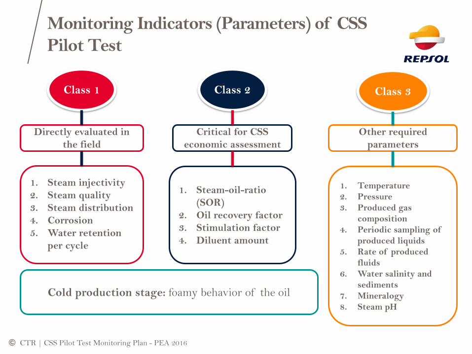
Monitoring Indicators (Parameters) of CSS
Pilot Test
Class 1 Class 2 Class 3
1. Steam injectivity
2. Steam quality
3. Steam distribution
4. Corrosion
5. Water retention
per cycle
1. Steam-oil-ratio
(SOR)
2. Oil recovery factor
3. Stimulation factor
4. Diluent amount
1. Temperature
2. Pressure
3. Produced gas
composition
4. Periodic sampling of
produced liquids
5. Rate of produced
fluids
6. Water salinity and
sediments
7. Mineralogy
8. Steam pH
Directly evaluated in
the field
Critical for CSS
economic assessment
Other required
parameters
Cold production stage: foamy behavior of the oil

© ©
Monitoring Technologies/Tools
or Methods
CTR | CSS Pilot Test Monitoring Plan - PEA 2016

©
Monitoring Technologies
CTR | CSS Pilot Test Monitoring Plan - PEA 2016
Monitoring
Technology
Core
Sampling
Observation
Well
4D Time-Lapse
Seismic
Cross-well
Seismic
Fiber Optic
Sensors
Steam quality
Tools
Corrosion
evaluation
methods
Well Logging
© CTR | CSS Pilot Test Monitoring Plan - PEA 2016
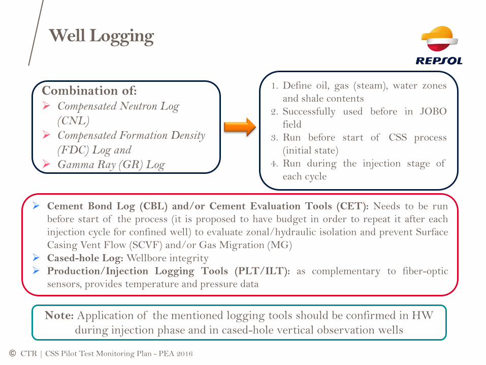
Combination of: Compensated Neutron Log
(CNL)
Compensated Formation Density
(FDC) Log and
Gamma Ray (GR) Log
1. Define oil, gas (steam), water zones
and shale contents
2. Successfully used before in JOBO
field
3. Run before start of CSS process
(initial state)
4. Run during the injection stage of
each cycle
Well Logging
Cement Bond Log (CBL) and/or Cement Evaluation Tools (CET): Needs to be run
before start of the process (it is proposed to have budget in order to repeat it after each
injection cycle for confined well) to evaluate zonal/hydraulic isolation and prevent Surface
Casing Vent Flow (SCVF) and/or Gas Migration (MG)
Cased-hole Log: Wellbore integrity
Production/Injection Logging Tools (PLT/ILT): as complementary to fiber-optic
sensors, provides temperature and pressure data
Note: Application of the mentioned logging tools should be confirmed in HW
during injection phase and in cased-hole vertical observation wells

© CTR | CSS Pilot Test Monitoring Plan - PEA 2016
o Pressure-Temperature combined Gauges (P/T Gauges)
o Array Temperature Sensors (ATS)
o High-Density–Array Temperature Sensors (LxATS)
o P/T plus ATS
o Flowmeters plus P/T Gauges
o Distributed Acoustic Sensing (DAS) System
o Distributed Temperature Sensing (DTS) System
Fiber-Optic Sensors (FOS)

©
LxATS Sensors - (FOS)
CTR | CSS Pilot Test Monitoring Plan - PEA 2016
Calibrated temperature: 77 𝑡𝑜 572℉ / 25 𝑡𝑜 300℃
Thermal Accuracy: ±0.9℉ / ±0.5℃
Thermal Resolution: ±0.018℉ / ±0.01℃
Extended Temp. range to 630℉ / 330℃ possible
Calibrated P range: Atm to 2000 psi / Atm to 138 Bar
Max. Non-Operating P: > 6000 𝑝𝑠𝑖 / > 413 𝐵𝑎𝑟
Pressure Accuracy: ±3 𝑝𝑠𝑖 / ±0.2 𝐵𝑎𝑟
Pressure Resolution: ≤ 0.1 𝑝𝑠𝑖 / ≤ 0.007 𝐵𝑎𝑟
Retreivable up to 15 times
Electromagnetic Inspection (EMI), hydrogen
insensitive and safe in high T environments
Life time greater than 15 years
© CTR | CSS Pilot Test Monitoring Plan - PEA 2016
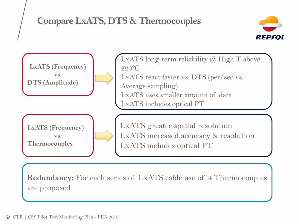
Compare LxATS, DTS & Thermocouples
LxATS (Frequency)
vs.
DTS (Amplitude)
LxATS long-term reliability @ High T above
220℃
LxATS react faster vs. DTS (per/sec vs.
Average sampling)
LxATS uses smaller amount of data
LxATS includes optical PT
LxATS (Frequency)
vs.
Thermocouples
LxATS greater spatial resolution
LxATS increased accuracy & resolution
LxATS includes optical PT
Redundancy: For each series of LxATS cable use of 4 Thermocouples
are proposed

©
Observation Well (OBS)
CTR | CSS Pilot Test Monitoring Plan - PEA 2016
o Widely used in pilot test and EOR
evaluations
o At least two OBS is proposed (Middle
and Toe) Should not be in the same side
of the HW
o Simulation studies to define optimum
location
o Fiber-optic sensors and cross-well
seismic (recommended side-wall core
sampling and well logging)
o Reservoir Saturation Tool (RST)
logging
©
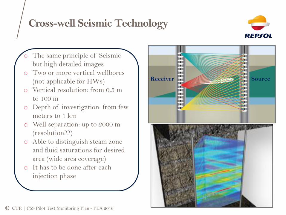
Cross-well Seismic Technology
CTR | CSS Pilot Test Monitoring Plan - PEA 2016
o The same principle of Seismic
but high detailed images
o Two or more vertical wellbores
(not applicable for HWs)
o Vertical resolution: from 0.5 m
to 100 m
o Depth of investigation: from few
meters to 1 km
o Well separation: up to 2000 m
(resolution??)
o Able to distinguish steam zone
and fluid saturations for desired
area (wide area coverage)
o It has to be done after each
injection phase
Source Receiver

© CTR | CSS Pilot Test Monitoring Plan - PEA 2016
4D TIME-LAPSE SEISMIC
o Wide range of reservoir
coverage
o Distinguish phases (Steam
and liquid)
o It is proposed to perform
baseline seismic survey
o For better understanding
in future evaluations
o It is recommended to have
budget for at least three
surveys (including the
base line) along the pilot
test

©
Advantages and Limitations
CTR | CSS Pilot Test Monitoring Plan - PEA 2016
Key
Strengths
Key
Limitations
1. Do not require permanent installation
2. Repeat survey can be done when necessary
3. Well adapted for evaluating the drainage areas and
bypassed areas, after some time of oil production
4. Larger area coverage than well logging and observation
wells
1. Not continuous in time thus can miss the right moment to
raise an alarm to make some operational decisions
2. Cost per Km2 increases rapidly for small survey areas
3. Operationally not adequate for a monitoring frequency lower
than a repeat once a year
4. Accuracy of time-lapse observations can be limited by
variations in the near surface conditions due to seasonal
changes
4D TIME-LAPSE SEISMIC

© CTR | CSS Pilot Test Monitoring Plan - PEA 2016
Steam quality Measurement at Well head
o Thermal neutron (Gamma) transmission
principle
o Large mass attenuation of thermal
neutrons in liquid water
o Mounted on the outside of the pipe
o Weakly attenuated by pipe wall material
o Measure steam quality @ wellhead
o Portable, non-intrusive and safe for field
use
o Combine with Flow nozzle provide mass
flow rate too
o The availability in market should be
checked
Neutron Densitometer

© CTR | CSS Pilot Test Monitoring Plan - PEA 2016
Redundant Steam quality Methods
Total
Dissolved
Solids
(TDS)
Orifice
meter
Technique
1. Compare concentration of soluble solids in
feedwater and liquid portion of generator output
2. Adding dilute acid to find concentration (Chemical
titration-Phenolphthalein indicator)
3. Ratio of added acid for output water and feedwater
(5 times more acid for output means 80% quality)
4. Very accurate and most widely used
5. Sampling is critical and important process (avoid
sampling at bends, tees, elbows or pipe fittings
1. Measures gas and liquid flowrates
2. No need to phase separator or sampling
3. Appropriate for very high quality
4. Comparable with other methods like TDS
5. Continuous and online measurements
6. It is an approximate and measurements should be
done at least 10 min after the steady-state flow
After generator

© CTR | CSS Pilot Test Monitoring Plan - PEA 2016
Corrosion Evaluation Methods
Production
Stage
Injection
Stage
1. Gas Chromatograph: H2S and CO2
concentrations
2. H2S Dragger: as complementary to Gas
Chromatograph
3. Metallic Coupons weight loss, stress corrosion
cracking, X-Ray diffraction of corrosion
products and electronic microscopic analysis
4. Remote Monitoring System (state-of-the-art)
1. Fresh feed water (low impurities and scales)
2. Steam pH of 9-11: minimize the acidic and
corrosive effect of steam and reduce quartz
dissolution
© CTR | CSS Pilot Test Monitoring Plan - PEA 2016
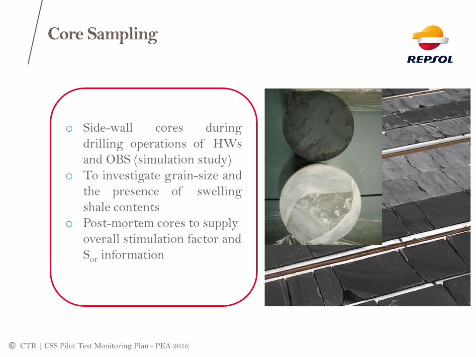
o Side-wall cores during
drilling operations of HWs
and OBS (simulation study)
o To investigate grain-size and
the presence of swelling
shale contents
o Post-mortem cores to supply
overall stimulation factor and
Sor information
Core Sampling

© ©
Simulation Studies
(T-P profile and Observation well location)
CTR | CSS Pilot Test Monitoring Plan - PEA 2016

© CTR | CSS Pilot Test Monitoring Plan - PEA 2016
CSS PILOT TEST CONCEPTUAL DESIGN

©
Simulation Studies Objectives
o A Sector of well-pad area selected
o Horizontal well lengths of 2200 ft and 4500 ft with Observation
wells at middle point and toe
o Recommended Pilot Plan production and injection constraints
o Objectives: o Optimum placement of vertical observation wells
o Performance of CSS pilot test and expected results
CTR | CSS Pilot Test Monitoring Plan - PEA 2016
Oil Saturation Permeability, mD Porosity

©
Grid Refinements (Discretization)
CTR | CSS Pilot Test Monitoring Plan - PEA 2016
o Highly discretized cells along the HW, OBS wells and their Surrounding area
o Grid refinement o along wellbore horizontal section
o around wellbore horizontal section
o In the middle and toe section of the wellbore vertically to the top (OBS well
locations)
©
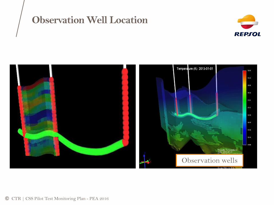
Observation Well Location
CTR | CSS Pilot Test Monitoring Plan - PEA 2016
Cross-well
Seismic View
Observation wells

©
Temperature - Pressure Profile
CTR | CSS Pilot Test Monitoring Plan - PEA 2016
Vertical growth of steam zone at Observation well location 7 m away from HW
Pressure, psi
Temperature, F
Ste
am
Heig
ht,
m
Tre
s
4 m (18 ft)
8 m (24 ft)
16.5 m (54 ft)
tend 1st Inj
tend 2nd Inj
tend 3rd Inj
©
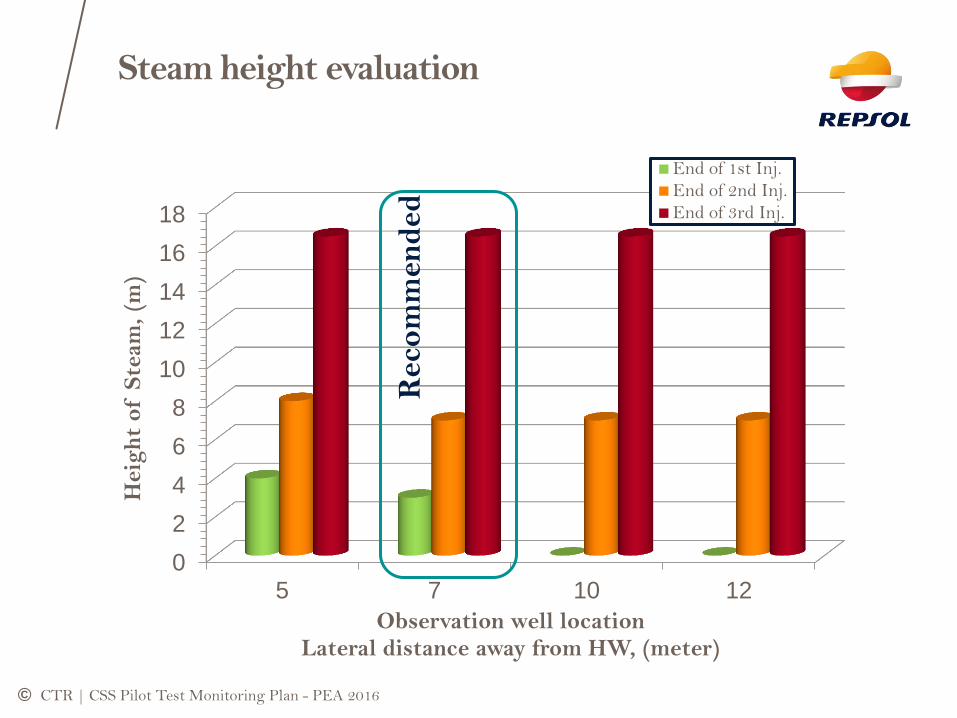
Steam height evaluation
CTR | CSS Pilot Test Monitoring Plan - PEA 2016
0
2
4
6
8
10
12
14
16
18
5 7 10 12
Heig
ht
of S
team
, (m
)
Observation well location Lateral distance away from HW, (meter)
End of 1st Inj.
End of 2nd Inj.
End of 3rd Inj.
Reco
mm
en
ded

©
Schematic of the HW and Obs. Well
CTR | CSS Pilot Test Monitoring Plan - PEA 2016
16,5 m (54 ft)
Top of the reservoir
7 meter away laterally Zero (Same level)
10 m (32 ft)
HW
Ob
servatio
n W
ell
Horizontal
Well
Ob
serv
ati
on
Well

©
T-time and P-time Profile
(lateral distances of 7 m away from HW)
CTR | CSS Pilot Test Monitoring Plan - PEA 2016
Pre
ssu
re, p
si
Vertical distance above HW:
Zero (same level)
10 m (32 ft)
16.5 m (54 ft) top of reservoir
Vertical distance above HW:
Zero (same level)
10 m (32 ft)
16.5 m (54 ft) top of reservoir

© ©
Monitoring Plan
CTR | CSS Pilot Test Monitoring Plan - PEA 2016

© CTR | CSS Pilot Test Monitoring Plan - PEA 2016
Injection Period
Feed Water
Steam Generator Surface Wellh
ead
Heel Toe
0
1
2
3 6
Ob
s. Well - M
id
4
Ob
s. Well - T
oe
5
© CTR | CSS Pilot Test Monitoring Plan - PEA 2016
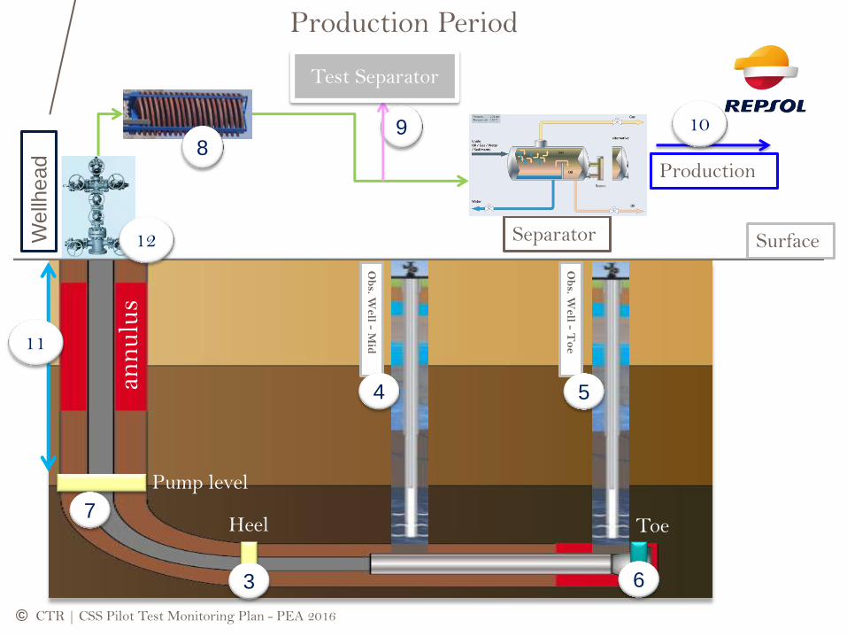
Production Period
Surface
Heel Toe
3 6
Ob
s. Well - M
id
4
Ob
s. Well - T
oe
5
Production
Separator Wellh
ead
10 9 8
Test Separator
11
Pump level
7
12
ann
ulu
s

©
Class 1: Indicators
Parameter Measurement tool /
Technique Frequency Relevance
Steam Quality (Xs)
@ Wellhead: Neutron densitometer
Daily
Heat loss management and
economic evaluation
After generator: TDS and/or
Orifice method Periodically or daily
@ Bottom-hole: using wellbore
model simulator to history match T
& P at sand face
Daily
Steam Injectivity Steam injection rate and
pressure at wellhead Daily
Reservoir injectivity,
swelling effect of shale
contents
Steam Distribution T-P profile from fiber-optic
sensors along the HW and OBS
wells and cross-well seismic data
Daily in case of FO
sensors,
At the end of each
injection phase for cross-
well seismic
Steam zone extension,
vertical and horizontal sweep
efficiency
Water retention per
cycle Material balance End of each cycle
Change in wettability,
relative permeability hysteresis,
Corrosion evaluation
@ Inj. Phase: keep steam pH 9-
11 by adding caustic materials Daily
Safety of personnel,
facilities and process
@ Prod. Phase: Metallic
coupons: weight loss, stress
corrosion cracking, X-Ray
diffraction of corrosion products
and electronic microscopic analysis
Possibly: Remote corrosion
monitoring system
Per Cycle
Real time
CTR | CSS Pilot Test Monitoring Plan - PEA 2016

© CTR | CSS Pilot Test Monitoring Plan - PEA 2016
Parameter Measurement tool
/ Technique Frequency Relevance
Inc. SOR Calculation:
qs/qoinc Daily
Economy of the
process, Energy
management
Oil recovery factor
(RF)
Calculation:
Net Np/NSTOIIP
End of each cycle
and end of the process
Economy of the
process
Stimulation factor Calculation:
qohot/qocold End of each cycle
and end of process Economy evaluation
Diluent amount Material Balance Daily Economy evaluation
Class 2: Indicators

©
Class 3: Indicators
CTR | CSS Pilot Test Monitoring Plan - PEA 2016
Parameter Measurement type Frequency Relevance
Temperature and
Pressure
Fiber-optic sensors /
thermocouples
Daily
Heat
management and
energy balance
Produced gases
composition
Gas chromatography and
H2S Dragger Daily
Corrosion, safety and
Steam distillation
effects
Oil, Gas, Water and
Steam production
rate
Appropriate flow meters at
surface Monthly
Material balance
calculations
Produced Oil
composition and
characteristics
Sampling of produced
liquids Periodic
Density, viscosity
and composition,
Water salinity and
Sediments
Surface facility and Laboratory
analysis
From six months before start of first steam injection
period: monthly measurements
From one month before start of first steam injection
period: weekly measurements and
The last week measurement should be done on the last
day before steam injection.
However, during the hot production phase the plan is
different and sampling is done in the following way: for
first week of hot production daily measurement, from
second week to the fourth week, weekly measurement
and then monthly sampling. It is repeated for the other
cycles too.
Presence of
mobile water,
thief or high
permeable zone
and sand
production rate
Steam pH pH meter at well head or after
generator Daily during injection phase
Corrosion
evaluation
Mineralogy Side-wall coring, mud cuttings,
well logging
During and after well drilling operations (HW and
Observation wells) Shale contents

©
Final Remarks
A pilot test can be successful or unsuccessful depending on
the applied technology or reservoir conditions. However, a
pilot test will be conclusive or non-conclusive depending on
the appropriate execution of an all-inclusive monitoring plan
Cost reduction, related to the partial execution of monitoring
plan, would be a big risk leading to a non-conclusive pilot
test (waste of time and money)
CTR | CSS Pilot Test Monitoring Plan - PEA 2016

©
THANK YOU
CTR | CSS Pilot Test Monitoring Plan - PEA 2016
Related Documents