Welcome message from author
This document is posted to help you gain knowledge. Please leave a comment to let me know what you think about it! Share it to your friends and learn new things together.
Transcript
64.0
Monarch M-Series A.C. Hydraulic Power Systems
Introduction
This catalogue illustrates the technical specifications forMonarch's A.C. range of Hydraulic Power Units. Designed forcompactness and durability, millions of A.C. Series systems havebeen sold worldwide for actuating materials handling, transport,construction, defense, access, machine tool, ergonomic, and otherlabor saving devices.
The Monarch name is synonymous with precise and cost-efficient designs, robust construction and rapid backup service.Under the direction of the Jackoboice family for over 150 years thecompany continues to strive for your confidence by offeringpersonal, reliable service and "Quality Machinery Since 1856" tocustomers around the world.
Mission Statement
Monarch designs, manufactures and delivers innovative fluidpower solutions and provides unparalleled support for itscustomers.
Quality Policy
Monarch Hydraulics will provide its customers with productsand services of continually improving quality to the mutualsatisfaction of all parties.
Monarch Value Statements
• Monarch will be honest, moral and ethical.• Monarch will accept responsibility for its actions.• Monarch will treat people with equality.• Monarch will remain a family business.• Monarch will make a profit.
Specifications, descriptions and illustrative material contained herein were as accurate as known at the time this publication was approvedfor printing. Monarch Hydraulics, Inc. reserves the right to discontinue models at any time, or change specifications or designs without noticeor incurring obligation.
Prototype Policy
We invite you to try our Prototype Program forSolutions to Your Special Hydraulic Needs.
While Monarch offers a broad line of hydraulicsystems and components, it is impossible toanticipate the needs of every customer, especiallythose developing new products. Our uniqueprototype program allows us to respond to yourspecific needs when an existing "catalogue model"does not fit your application.
To participate in this program, simply submit a print,schematic, or sketch of the hydraulic power packthat you need along with a purchase order. We willreview the system requirements with you and thenmanufacture the system that we believe will satisfyyour objectives. The unit will be invoiced at anagreed upon price and marked Prototype.
You have 90 days free use of this product fortesting and evaluation from the date of invoice. Atthe end of this period you can (1) extend the testingand evaluation period for an additional 90 days or (2)purchase the unit as invoiced (and order more ifneeded) or (3) return the unit via prepaidtransportation for full credit.
There is no risk to you. Just the opportunity to solveyour hydraulic problem with the performance andquality of Monarch Hydraulics.
Monarch M-Series A.C. Hydraulic Power Systems
Monarch Hydraulics, Inc.
1.0
Table of Contents
Introduction ........................................................... 0.0Mission Statement ................................................. 0.0Quality Policy ........................................................ 0.0Monarch Value Statements .................................... 0.0Prototype Policy ................................................... 0.0Features and Options ............................................ 2.0How to Use This Product Guide ............................ 3.0M-400 Series Power System Selection Guide ....... 4.0M-400 Series Pump/Motor Performance Data ...... 5.0M-400 Series Motor Information ............................ 6.0Dimensional Information for Standard M-400
Motors With Flexible Couplings ....................... 7.0Reservoirs for M-400 Units .................................. 10.0Reservoirs for Mini Units ..................................... 11.0M Series Reservoirs ............................................ 12.0Valves for M-400 Series Units ............................. 13.0M-400 Series Accessories .................................. 15.0Hand Pumps ....................................................... 16.0Monarch A.C. Hydraulic Power Systems ............ 21.0Model M-455 Mini System ................................... 22.0Model M-426 ....................................................... 23.0Model M-454 Mini System ................................... 24.0Model M-404 ....................................................... 25.0Model M-413 ....................................................... 26.0Model M-4509 ..................................................... 27.0Model M-4509-C ................................................. 28.0Model M-401 ....................................................... 29.0Model M-415 ....................................................... 30.0Model M-459 Mini System ................................... 31.0Model M-458 Mini System ................................... 32.0Model M-419 ....................................................... 33.0Model M-4519-C ................................................. 34.0Model M-403 ....................................................... 35.0Model M-410 ....................................................... 36.0Model M-4551-C ................................................. 37.0Model M-452 Mini System ................................... 38.0Model M-453 Mini System ................................... 39.0Model M-4506 ..................................................... 40.0Model M-4505 ..................................................... 41.0Model M-428 ....................................................... 42.0Model M-428-P ................................................... 43.0Model M-4528 ..................................................... 44.0Model M-466 Mini System ................................... 45.0Model M-457 Mini System ................................... 46.0Model M-4593-C ................................................. 47.0
• Always wear eye protection and protectiveclothing when working on and around hydraulicsystems.
• Remove jewelry and objects that mightconduct electricity while working on powerunits.
• Hydraulic fluid does pose a fire hazard, cancause burning or skin irritation if not properlyhandled.
• Fluid under pressure can pierce the skinand enter the bloodstream causing death orserious injury.
• Devices being operated by the hydraulicsystem should be immobilized so they cannotmove and cause injury while being inspected orrepaired. Disconnect from electrical source.
• Prior to performing any maintenance makesure the equipment is turned off and that anystored energy, or example pressure, is re-leased. Also, extended equipment or cylindersshould be lowered and mechanically locked asrequired.
• Monarch Hydraulics is not responsible formisuse or misapplication of product. If youhave any questions about application, pleaseconcact local dealer.
• Fluids should be contained and disposed ofproperly.
! WARNING
MT & T Series Industrial Power Units .................. 49.0MT & T Series Performance Data ....................... 52.0Standard D03 and D05 Directional Control Valves ........................................................... 53.0MT-400 and T-400 Selection Guide ..................... 54.0Warranty ............................................................. 56.0
2.0
Monarch M-Series A.C. Hydraulic Power Systems
Features and Benefits
STANDARD M-400 SERIES FEATURES
• FLEXIBLE COUPLING EXTENDS PUMP LIFE,ELIMINATES MISALIGNMENT
• ACCEPTS STANDARD NEMA 56C THROUGH 184CMOTORS
• ALL POWDERED METAL GEARS
• HARDCOATED PUMP END PLATES FORUNMATCHED DURABILITY IN DEMANDINGENVIRONMENTS AND SEVERE DUTYAPPLICATIONS
• EXTERNALLY ADJUSTABLE RELIEF VALVE WITHLOCK NUT
• 1 YEAR LIMITED WARRANTY ON SYSTEM
• MONARCH'S PERSONAL CUSTOMER SERVICE
• 24 HOUR SHIPMENT ON MOST PARTS ORDERS
• OVER TWO MILLION POWER UNITS SOLD
• WORLDWIDE DISTRIBUTOR NETWORK
OPTIONS
• PRESSURE GAUGES
• SAE PORTS ON MOST MODELS
• COMPLETE SELECTION OF NFPA DO3 CONTROLVALVES AND AUXILIARY VALVES
CROSS PORT RELIEF
PRESSURE REDUCING
SINGLE AND DOUBLE FLOW CONTROL
DIRECT AND PILOT OPERATED CHECK
SEQUENCE
COUNTER BALANCE
RELIEF
• PRESSURE SWITCHES
• WATER/OIL HEAT EXCHANGERS
• FLOAT SWITCHES
• RESERVOIRS
• 56 FRAME AIR MOTORS
• EXPLOSION PROOF, 50 HERTZ, CHEMICAL DUTY,DUAL FREQUENCY, METRIC FRAME, HIGHTORQUE AND SPECIAL DUTY ELECTRIC MOTORS
• GASOLINE AND DIESEL ENGINES
• CLOSE COUPLED MOTORS AVAILABLE ON MANYSYSTEMS
3.0
Monarch Hydraulics, Inc.
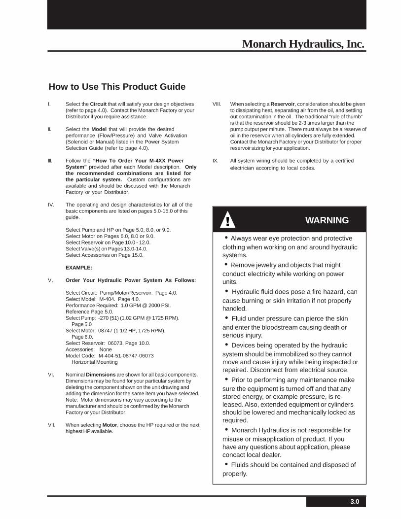
How to Use This Product Guide
I. Select the Circuit that will satisfy your design objectives(refer to page 4.0). Contact the Monarch Factory or yourDistributor if you require assistance.
II. Select the Model that will provide the desiredperformance (Flow/Pressure) and Valve Activation(Solenoid or Manual) listed in the Power SystemSelection Guide (refer to page 4.0).
III. Follow the “How To Order Your M-4XX PowerSystem” provided after each Model description. Onlythe recommended combinations are listed forthe particular system. Custom configurations areavailable and should be discussed with the MonarchFactory or your Distributor.
IV. The operating and design characteristics for all of thebasic components are listed on pages 5.0-15.0 of thisguide.
Select Pump and HP on Page 5.0, 8.0, or 9.0.Select Motor on Pages 6.0, 8.0 or 9.0.Select Reservoir on Page 10.0 - 12.0.Select Valve(s) on Pages 13.0-14.0.Select Accessories on Page 15.0.
EXAMPLE:
V. Order Your Hydraulic Power System As Follows:
Select Circuit: Pump/Motor/Reservoir. Page 4.0.Select Model: M-404. Page 4.0.Performance Required: 1.0 GPM @ 2000 PSI.Reference Page 5.0.Select Pump: -270 (51) (1.02 GPM @ 1725 RPM).
Page 5.0Select Motor: 08747 (1-1/2 HP, 1725 RPM).
Page 6.0.Select Reservoir: 06073, Page 10.0.Accessories: NoneModel Code: M-404-51-08747-06073
Horizontal Mounting
VI. Nominal Dimensions are shown for all basic components.Dimensions may be found for your particular system bydeleting the component shown on the unit drawing andadding the dimension for the same item you have selected.Note: Motor dimensions may vary according to themanufacturer and should be confirmed by the MonarchFactory or your Distributor.
VII. When selecting Motor, choose the HP required or the nexthighest HP available.
VIII. When selecting a Reservoir, consideration should be givento dissipating heat, separating air from the oil, and settlingout contamination in the oil. The traditional “rule of thumb”is that the reservoir should be 2-3 times larger than thepump output per minute. There must always be a reserve ofoil in the reservoir when all cylinders are fully extended.Contact the Monarch Factory or your Distributor for properreservoir sizing for your application.
IX. All system wiring should be completed by a certifiedelectrician according to local codes.
• Always wear eye protection and protectiveclothing when working on and around hydraulicsystems.
• Remove jewelry and objects that mightconduct electricity while working on powerunits.
• Hydraulic fluid does pose a fire hazard, cancause burning or skin irritation if not properlyhandled.
• Fluid under pressure can pierce the skinand enter the bloodstream causing death orserious injury.
• Devices being operated by the hydraulicsystem should be immobilized so they cannotmove and cause injury while being inspected orrepaired. Disconnect from electrical source.
• Prior to performing any maintenance makesure the equipment is turned off and that anystored energy, or example pressure, is re-leased. Also, extended equipment or cylindersshould be lowered and mechanically locked asrequired.
• Monarch Hydraulics is not responsible formisuse or misapplication of product. If youhave any questions about application, pleaseconcact local dealer.
• Fluids should be contained and disposed ofproperly.
! WARNING
4.0
Monarch M-Series A.C. Hydraulic Power Systems
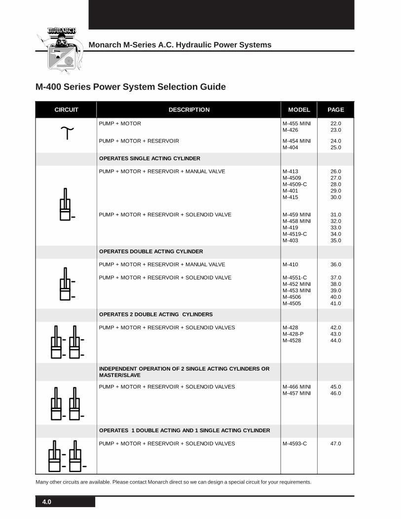
CIRCUIT DESCRIPTION MODEL PAGE
PUMP + MOTOR M-455 MINIM-426
22.023.0
PUMP + MOTOR + RESERVOIR M-454 MINIM-404
24.025.0
OPERATES SINGLE ACTING CYLINDER
PUMP + MOTOR + RESERVOIR + MANUAL VALVE M-413M-4509M-4509-CM-401M-415
26.027.028.029.030.0
PUMP + MOTOR + RESERVOIR + SOLENOID VALVE M-459 MINIM-458 MINIM-419M-4519-CM-403
31.032.033.034.035.0
OPERATES DOUBLE ACTING CYLINDER
PUMP + MOTOR + RESERVOIR + MANUAL VALVE M-410 36.0
PUMP + MOTOR + RESERVOIR + SOLENOID VALVE M-4551-CM-452 MINIM-453 MINIM-4506M-4505
37.038.039.040.041.0
OPERATES 2 DOUBLE ACTING CYLINDERS
PUMP + MOTOR + RESERVOIR + SOLENOID VALVES M-428M-428-PM-4528
42.043.044.0
INDEPENDENT OPERATION OF 2 SINGLE ACTING CYLINDERS ORMASTER/SLAVE
PUMP + MOTOR + RESERVOIR + SOLENOID VALVES M-466 MINIM-457 MINI
45.046.0
OPERATES 1 DOUBLE ACTING AND 1 SINGLE ACTING CYLINDER
PUMP + MOTOR + RESERVOIR + SOLENOID VALVES M-4593-C 47.0
M-400 Series Power System Selection Guide
Many other circuits are available. Please contact Monarch direct so we can design a special circuit for your requirements.
5.0
Monarch Hydraulics, Inc.
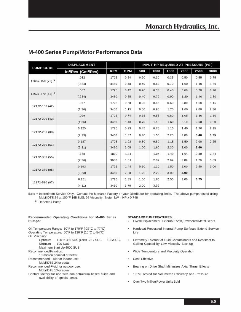
PUMP CODEDISPLACEMENT INPUT HP REQUIRED AT PRESSURE (PSI)
RPM GPM 500 1000 1500 2000 2500 3000
12637-150 (72) *.032 1725 0.24 0.20 0.30 0.35 0.50 0.55 0.75
(.524) 3450 0.48 0.40 0.60 0.70 1.00 1.10 1.50
12637-270 (62) *.057 1725 0.42 0.20 0.35 0.45 0.60 0.70 0.90
(.934) 3450 0.85 0.40 0.70 0.90 1.20 1.40 1.80
12172-150 (42).077 1725 0.58 0.25 0.45 0.60 0.80 1.00 1.15
(1.26) 3450 1.15 0.50 0.90 1.20 1.60 2.00 2.30
12172-200 (43).099 1725 0.74 0.35 0.55 0.80 1.05 1.30 1.50
(1.66) 3450 1.48 0.70 1.10 1.60 2.10 2.60 3.00
12172-250 (03)0.125 1725 0.93 0.45 0.75 1.10 1.40 1.70 2.15
(2.13) 3450 1.87 0.90 1.50 2.20 2.80 3.40 3.95
12172-270 (51)0.137 1725 1.02 0.50 0.80 1.15 1.50 2.00 2.25
(2.31) 3450 2.05 1.00 1.60 2.30 3.00 3.60
12172-330 (55).168 1800 1.31 1.04 1.49 1.94 2.39 2.84
(2.76) 3600 1.31 2.09 2.99 3.89 4.79 5.69
12172-380 (05)0.193 1725 1.44 0.60 1.10 1.50 2.00 2.50 3.00
(3.23) 3450 2.88 1.20 2.20 3.00 3.90
12172-510 (07)0.251 1725 1.85 1.00 1.65 2.50 3.00 3.75
(4.11) 3450 3.70 2.00 3.30
M-400 Series Pump/Motor Performance Data
Bold = Intermittent Service Only. Contact the Monarch Factory or your Distributor for operating limits. The above pumps tested usingMobil DTE 24 at 100°F 165 SUS, 95 Viscosity. Note: kW = HP x 0.746
* Denotes i-Pump
Recommended Operating Conditions for M-400 SeriesPumps:
Oil Temperature Range: 10°F to 170°F (-25°C to 77°C)Operating Temperature: 50°F to 130°F (10°C to 54°C)Oil Viscosity:
Optimum 100 to 350 SUS (Cst = .22 x SUS - 135/SUS)Minimum 100 SUSMaximum Start Up 4000 SUS
Recommended Filtration:10 micron nominal or better
Recommended Fluid for indoor use:Mobil DTE 24 or equal
Recommended Fluid for outdoor use:Mobil DTE 13 or equal
Contact factory for use with non-petroleum based fluids andavailability of special seals.
STANDARD PUMP FEATURES:• Fixed Displacement, External Tooth, Powdered Metal Gears
• Hardcoat Processed Internal Pump Surfaces Extend ServiceLife
• Extremely Tolerant of Fluid Contaminants and Resistant toGalling Caused by Low Viscosity Start-up
• Wide Temperature and Viscosity Operation
• Cost Effective
• Bearing on Drive Shaft Minimizes Axial Thrust Effects
• 100% Tested for Volumetric Efficiency and Pressure
• Over Two Million Power Units Sold
In3/Rev (Cm3/Rev)
6.0
Monarch M-Series A.C. Hydraulic Power Systems
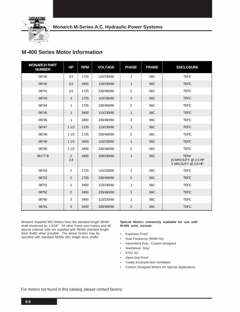
MONARCH PARTNUMBER
HP RPM VOLTAGE PHASE FRAME ENCLOSURE
08740 1/2 1725 115/230/60 1 56C TEFC
08742 1/2 3450 115/230/60 1 56C TEFC
08741 1/2 1725 230/460/60 3 56C TEFC
08743 1 1725 115/230/60 1 56C TEFC
08744 1 1725 230/460/60 3 56C TEFC
08745 1 3450 115/230/60 1 56C TEFC
08746 1 3450 230/460/60 3 56C TEFC
08747 1 1/2 1725 115/230/60 1 56C TEFC
08748 1 1/2 1725 230/460/60 3 56C TEFC
08749 1 1/2 3450 115/230/60 1 56C TEFC
08750 1 1/2 3450 230/460/60 3 56C TEFC
08177-B 22.8
3450 208/230/60 1 56C TENV15 MIN DUTY @ 2.0 HP5 MIN DUTY @ 2.8 HP
08754 2 1725 115/230/60 1 56C TEFC
08753 2 1725 230/460/60 3 56C TEFC
08751 2 3450 115/230/60 1 56C TEFC
08752 2 3450 230/460/60 3 56C TEFC
08760 3 3450 115/230/60 1 56C TEFC
08761 3 3450 230/460/60 3 56C TEFC
M-400 Series Motor Information
Monarch Supplied 56C Motors have the standard length NEMAshaft shortened by 1-3/16". All other frame size motors and allspecial ordered units are supplied with NEMA standard lengthdrive shafts when possible. The above motors may bespecified with standard NEMA 56C length drive shafts.
Special Motors commonly available for use withM-400 units include:
• Explosion Proof
• Dual Frequency (50/60 Hz)
• Intermittent Duty - Custom Designed
• Washdown Duty
• 575V AC
• Open Drip Proof
• Totally Enclosed Non-Ventilated
• Custom Designed Motors for Special Applications
For motors not found in this catalog, please contact factory.
7.0
Monarch Hydraulics, Inc.
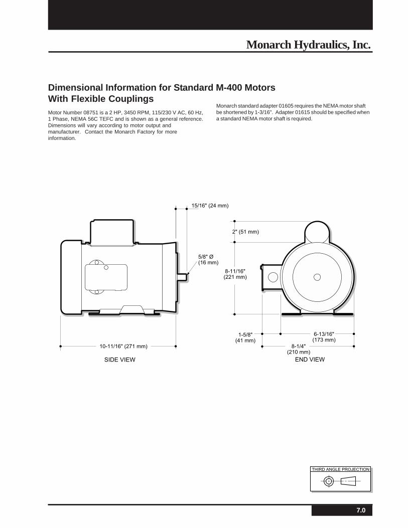
Dimensional Information for Standard M-400 MotorsWith Flexible CouplingsMotor Number 08751 is a 2 HP, 3450 RPM, 115/230 V AC, 60 Hz,1 Phase, NEMA 56C TEFC and is shown as a general reference.Dimensions will vary according to motor output andmanufacturer. Contact the Monarch Factory for moreinformation.
Monarch standard adapter 01605 requires the NEMA motor shaftbe shortened by 1-3/16". Adapter 01615 should be specified whena standard NEMA motor shaft is required.
15/16" (24 mm)
10-11/16" (271 mm) 8-1/4"(210 mm)
8-11/16"(221 mm)
2" (51 mm)
6-13/16"(173 mm)
1-5/8"(41 mm)
END VIEWSIDE VIEW
5/8" Ø(16 mm)
M-304
THIRD ANGLE PROJECTION
8.0
Monarch M-Series A.C. Hydraulic Power Systems
END VIEWSIDE VIEW
5-7/8"(149 mm)
1-5/8"(41 mm)
2-1/4" (57 mm)Single PhaseOnly
3"(76 mm)
8-7/16"(214 mm)
5-11/16"(144 mm)
Shown W/OptionalThermal Switch
END VIEWSIDE VIEW
"L"
6-1/4"(159 mm)
2-5/8"(67 mm)
4-11/16"(119 mm)
1-9/16" (40 mm)Single PhaseOnly
Shown W/OptionalThermal Switch
ShownW/Optional Base
"L" 08131 = 7-1/2" (191 mm)"L" 08132 = 8-1/16" (205 mm)
1-11/16"(43 mm)
MONARCHPART NUMBER
HP DUTY RPM VOLTAGE PHASE FRAME ENCLOSURE
08131 1/2 15 MINUTE 1725 115/230 1 42 TENV
08132 3/4 3 MINUTE 1725 115/230 1 42 TENV
08155 1 15 MINUTE 3450 115/230 1 48 TENV
08157 1 15 MINUTE 3450 230/460 3 48 TENV
08156 1 15 MINUTE 3450 575 3 48 TENV
08158 2.8 5 MINUTE 3450 208/230 1 56 TENV
08173-B 2.5 5 MINUTE 3450 208/230 1 56 TENV
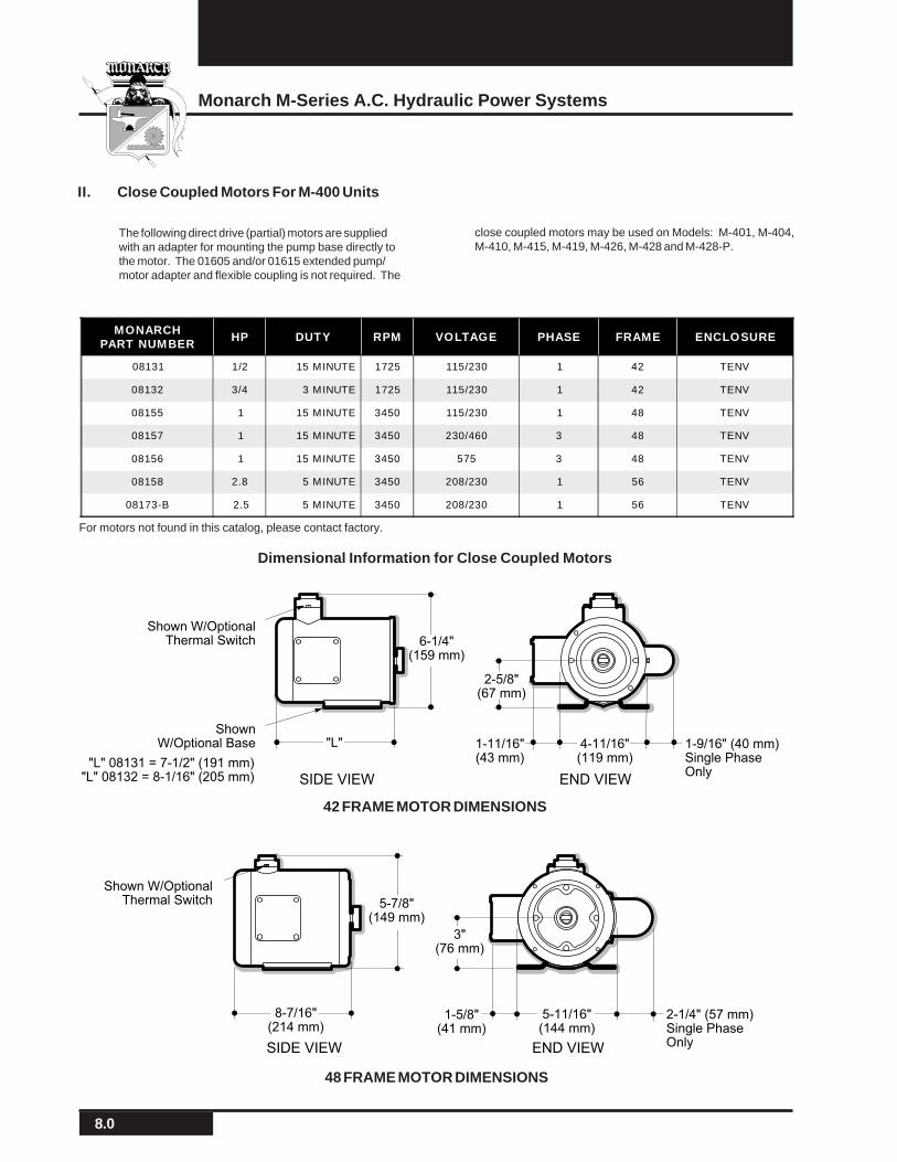
The following direct drive (partial) motors are suppliedwith an adapter for mounting the pump base directly tothe motor. The 01605 and/or 01615 extended pump/motor adapter and flexible coupling is not required. The
close coupled motors may be used on Models: M-401, M-404,M-410, M-415, M-419, M-426, M-428 and M-428-P.
II. Close Coupled Motors For M-400 Units
Dimensional Information for Close Coupled Motors
48 FRAME MOTOR DIMENSIONS
42 FRAME MOTOR DIMENSIONS
For motors not found in this catalog, please contact factory.
9.0
Monarch Hydraulics, Inc.
5-13/16"(148 mm)
3-13/16"(97 mm)
END VIEWSIDE VIEW
10 min.duty cycle max.
END VIEWSIDE VIEW
1-1/2" (38 mm)
6-1/2"(165 mm)
8-7/8"(225 mm)
3-1/2"(89 mm)
2-1/4" (57 mm)
PUMP CODEDISPLACEMENT
Maximum Run Time in Minutes at MaximumPressure (PSI) with 03862 Capacitor
RPM GPM 500 1000 1500 2000 2500 3000
12637-100 (70).021 1800 .16 7.6 7.7 8.0 8.4 8.9 9.5
(.34)
12637-120 (71).025 1800 .20 7.6 7.8 8.2 8.8 9.5 9.5
(.41)
12637-150 (72).032 1800 .25 7.7 7.8 8.6 9.5 9.5 9.5
(.524)
12637-270 (62).057 1800 .44 7.7 8.7 9.5 9.5
(.934)
12172-150 (42).077 1800 .60 9.1 9.5
(1.26)
Longer run time available with decrease in pressure. Contact Factory.
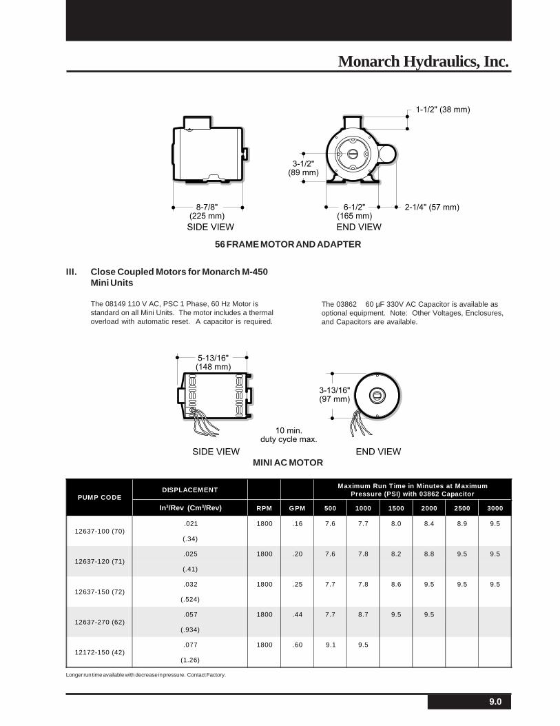
56 FRAME MOTOR AND ADAPTER
The 03862 60 µF 330V AC Capacitor is available asoptional equipment. Note: Other Voltages, Enclosures,and Capacitors are available.
III. Close Coupled Motors for Monarch M-450Mini Units
The 08149 110 V AC, PSC 1 Phase, 60 Hz Motor isstandard on all Mini Units. The motor includes a thermaloverload with automatic reset. A capacitor is required.
MINI AC MOTOR
In3/Rev (Cm3/Rev)
10.0
Monarch M-Series A.C. Hydraulic Power Systems
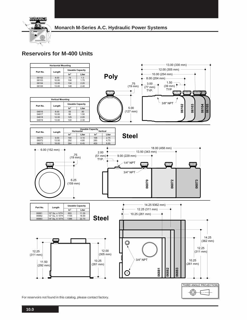
Reservoirs for M-400 Units
M-304
THIRD ANGLE PROJECTION
5.00
(127 mm)
2.00
(51 mm)
TYP.
6.25
(159 mm)
6.00 (152 mm)
12.25
(311 mm)
11.50
(292 mm)
10.25
(261 mm)
12.00
(305 mm)
1.50
(39 mm)
TYP.
3.00
(77 mm)
TYP.
8.00 (204 mm)
10.00 (254 mm)
12.00 (305 mm)
13.00 (330 mm)
13.50 (343 mm)
18.00 (458 mm)
10.25 (261 mm)
12.25 (311 mm)
14.25 9362 mm)
10.25
(261 mm)
12.25
(311 mm)
14.25
(362 mm)
9.00 (229 mm)
Part No. LengthIn3 Liter LiterIn3
Useable CapacityHorizontal Vertical
9.0013.50
18.00
190292
394
168285
405
2.754.70
6.65
3.104.80
6.45
0607006072
06073
Part No. LengthIn3 Liter
Useable Capacity
10" Sq. x 10"H12" Sq. X 10"H
14" Sq. X 10"H
6931155
1386
11.3518.90
22.70
0688106882
06883
Part No.
Horizontal Mounting
LengthIn3 Liter
Useable Capacity
8.0010.00
12.00
13.00
79106
134
148
1.31.75
2.20
2.40
0610206103
06104
06105
Part No.
Vertical Mounting
LengthIn3 Liter
Useable Capacity
8.0010.00
12.00
13.00
5590
125
140
.901.50
2.05
2.30
0461604617
04618
04619
Poly
Steel
Steel
06
10
2
06
88
1
06
88
2
06
88
3
06
07
2
06
07
0
06
07
3
06
10
3
06
10
4
06
10
53/8" NPT
1/4" NPT
3/4" NPT
3/4" NPT
.75(19 mm)
.75(19 mm)
For reservoirs not found in this catalog, please contact factory.
11.0
Monarch Hydraulics, Inc.
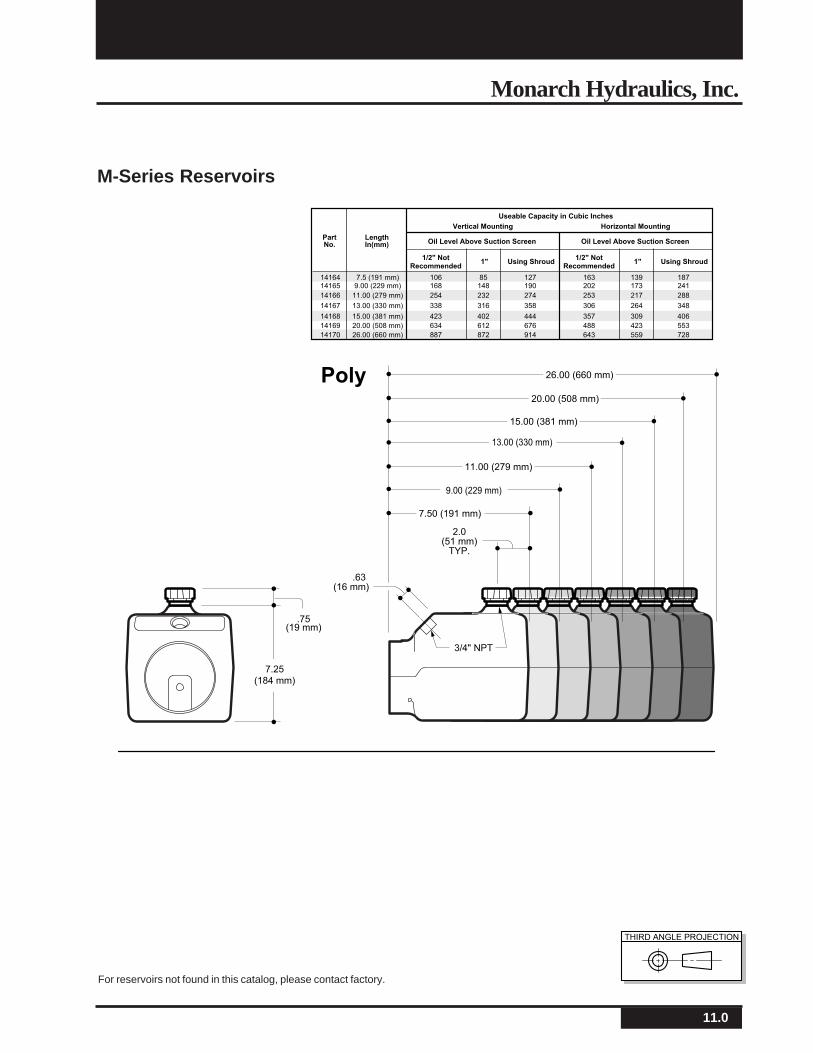
M-Series Reservoirs
M-304
THIRD ANGLE PROJECTION
7.25
(184 mm)
Poly
3/4" NPT
2.0(51 mm)
TYP.
.63(16 mm)
7.50 (191 mm)
9.00 (229 mm)
11.00 (279 mm)
13.00 (330 mm)
15.00 (381 mm)
20.00 (508 mm)
26.00 (660 mm)
.75(19 mm)
Horizontal MountingVertical Mounting
Useable Capacity in Cubic Inches
LengthIn(mm)
PartNo.
1/2" NotRecommended
1" Using Shroud
Oil Level Above Suction Screen
7.5 (191 mm)9.00 (229 mm)
11.00 (279 mm)
106168
254
1416414165
14166
85148
13.00 (330 mm) 33814167 316
232
26.00 (660 mm) 88714170 872
20.00 (508 mm) 63414169 612
15.00 (381 mm) 423
127190
274
358
914
676
44414168 402
1/2" NotRecommended
1" Using Shroud
Oil Level Above Suction Screen
163202
253
139173
306 264
217
643 559
488 423
357
187241
288
348
728
553
406309
For reservoirs not found in this catalog, please contact factory.
12.0
Monarch M-Series A.C. Hydraulic Power Systems
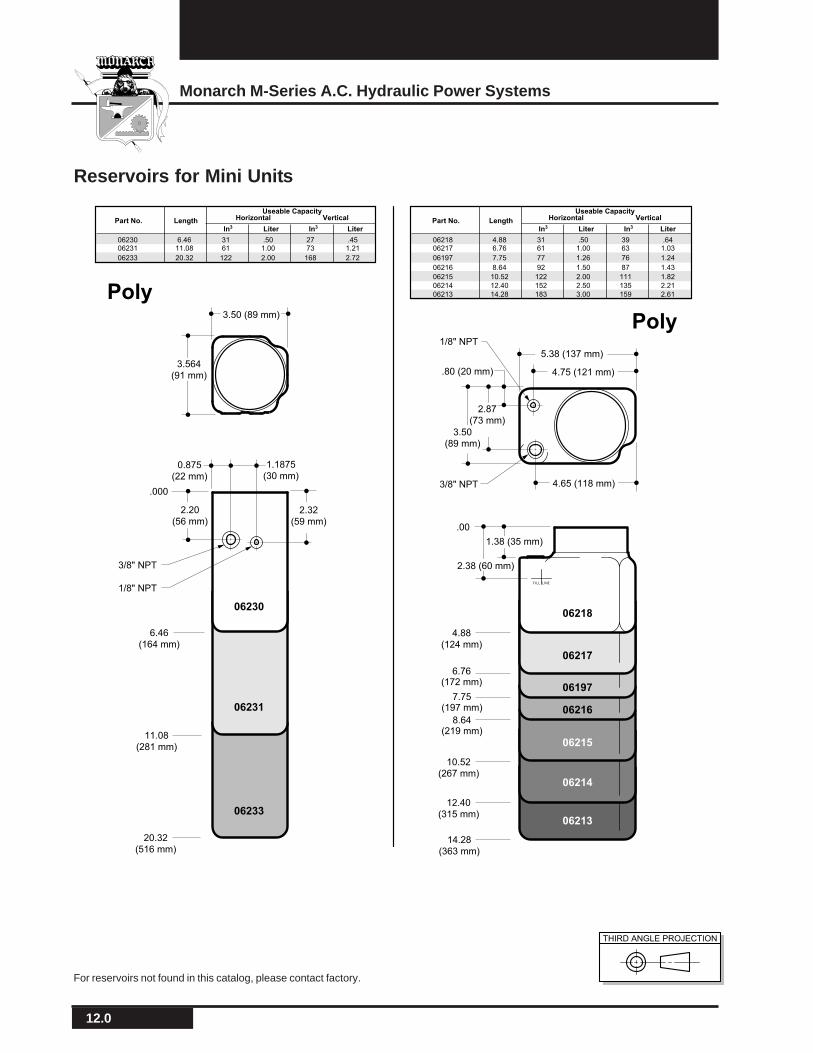
Reservoirs for Mini Units
M-304
THIRD ANGLE PROJECTION
F ILL LINE
06230
06231
0623306213
06214
06215
06216
06217
06197
06218
Part No. LengthIn3 Liter LiterIn3
Useable CapacityHorizontal Vertical
4.886.76
7.75
8.64
3161
77
92
3963
76
87
.641.03
1.24
1.43
.501.00
1.26
1.50
0621806217
06197
06216
10.52
12.40
14.28
122
152
183
111
135
159
1.82
2.21
2.61
2.00
2.50
3.00
06215
06214
06213
Part No. LengthIn3 Liter LiterIn3
Useable CapacityHorizontal Vertical
6.4611.08
20.32
3161
122
2773
168
.451.21
2.72
.501.00
2.00
0623006231
06233
Poly
Poly
0.875
(22 mm)
2.32
(59 mm)
.000
.00
4.88
(124 mm)
6.76(172 mm)
7.75(197 mm)
8.64(219 mm)
10.52
(267 mm)
12.40
(315 mm)
14.28
(363 mm)
6.46
(164 mm)
11.08
(281 mm)
20.32
(516 mm)
2.20
(56 mm)
1.1875
(30 mm)
3.564
(91 mm)
3.50
(89 mm)
5.38 (137 mm)
4.75 (121 mm)
2.87
(73 mm)
4.65 (118 mm)
2.38 (60 mm)3/8" NPT
1/8" NPT
3/8" NPT
1/8" NPT
.80 (20 mm)
3.50 (89 mm)
1.38 (35 mm)
For reservoirs not found in this catalog, please contact factory.
13.0
Monarch Hydraulics, Inc.
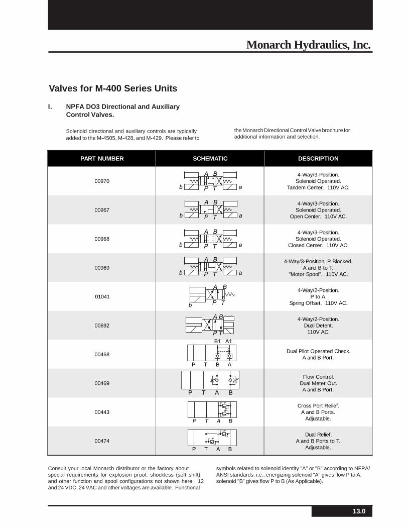
PART NUMBER SCHEMATIC DESCRIPTION
009704-Way/3-Position.
Solenoid Operated.Tandem Center. 110V AC.
009674-Way/3-Position.
Solenoid Operated.Open Center. 110V AC.
009684-Way/3-Position.
Solenoid Operated.Closed Center. 110V AC.
009694-Way/3-Position, P Blocked.
A and B to T."Motor Spool". 110V AC.
010414-Way/2-Position.
P to A.Spring Offset. 110V AC.
006924-Way/2-Position.
Dual Detent.110V AC.
00468Dual Pilot Operated Check.
A and B Port.
00469Flow Control.
Dual Meter Out.A and B Port.
00443Cross Port Relief.
A and B Ports.Adjustable.
00474Dual Relief.
A and B Ports to T.Adjustable.
Valves for M-400 Series Units
I. NPFA DO3 Directional and AuxiliaryControl Valves.
Solenoid directional and auxiliary controls are typicallyadded to the M-4505, M-428, and M-429. Please refer to
the Monarch Directional Control Valve brochure foradditional information and selection.
Consult your local Monarch distributor or the factory aboutspecial requirements for explosion proof, shockless (soft shift)and other function and spool configurations not shown here. 12and 24 VDC, 24 VAC and other voltages are available. Functional
symbols related to solenoid identity "A" or "B" according to NFPA/ANSI standards, i.e., energizing solenoid "A" gives flow P to A,solenoid "B" gives flow P to B (As Applicable).
A B
P T ab
A B
P T ab
A B
P T ab
A B
P T ab
A B
P Tb
A B
P T
B1 A1
P T B A
P T BA
P T A B
P T A B
14.0
Monarch M-Series A.C. Hydraulic Power Systems
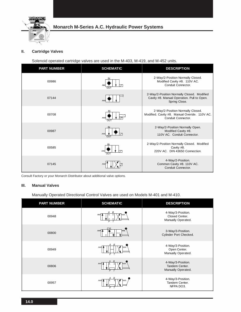
PART NUMBER SCHEMATIC DESCRIPTION
009484-Way/3-Position.
Closed Center.Manually Operated.
008003-Way/3-Position.
Cylinder Port Checked.
009494-Way/3-Position.
Open Center.Manually Operated.
008064-Way/3-Position.Tandem Center.
Manually Operated.
009574-Way/3-Position.Tandem Center.
NFPA DO3.
PART NUMBER SCHEMATIC DESCRIPTION
009862-Way/2-Position Normally Closed.
Modified Cavity #8. 110V AC.Conduit Connector.
071442-Way/2-Position Normally Closed. ModifiedCavity #8. Manual Operation. Pull to Open.
Spring Close.
007082-Way/2-Position Normally Closed.
Modified. Cavity #8. Manual Overide. 110V AC.Conduit Connector.
009872-Way/2-Position Normally Open.
Modified Cavity #8.110V AC. Conduit Connector.
005852-Way/2-Position Normally Closed. Modified
Cavity #8.220V AC. DIN 43650 Connection.
071454-Way/2-Position.
Common Cavity #8. 110V AC.Conduit Connector.
II. Cartridge Valves
Solenoid operated cartridge valves are used in the M-403, M-419, and M-452 units.
Consult Factory or your Monarch Distributor about additional valve options.
III. Manual Valves
Manually Operated Directional Control Valves are used on Models M-401 and M-410.
IN
OUT
OUT
IN
IN
OUT
IN
OUT
A B
P T
CYL
A B
P T
A B
P T
A B
P T
15.0
Monarch Hydraulics, Inc.
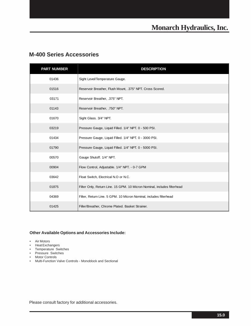
PART NUMBER DESCRIPTION
01436 Sight Level/Temperature Gauge.
01516 Reservoir Breather, Flush Mount, .375" NPT. Cross Scored.
03171 Reservoir Breather, .375" NPT.
01143 Reservoir Breather, .750" NPT.
01670 Sight Glass. 3/4" NPT.
03219 Pressure Gauge, Liquid Filled. 1/4" NPT. 0 - 500 PSI.
01434 Pressure Gauge, Liquid Filled. 1/4" NPT. 0 - 3000 PSI.
01790 Pressure Gauge, Liquid Filled. 1/4" NPT. 0 - 5000 PSI.
00570 Gauge Shutoff. 1/4" NPT.
00904 Flow Control, Adjustable. 1/4" NPT. - 0-7 GPM
03642 Float Switch, Electrical N.O or N.C.
01875 Filter Only, Return Line. 15 GPM. 10 Micron Nominal, includes filterhead
04369 Filter, Return Line. 5 GPM. 10 Micron Nominal, includes filterhead
01425 Filler/Breather, Chrome Plated. Basket Strainer.
M-400 Series Accessories
Other Available Options and Accessories Include:
• Air Motors• Heat Exchangers• Temperature Switches• Pressure Switches• Motor Controls• Multi-Function Valve Controls - Monoblock and Sectional
Please consult factory for additional accessories.
16.0
Monarch M-Series A.C. Hydraulic Power Systems
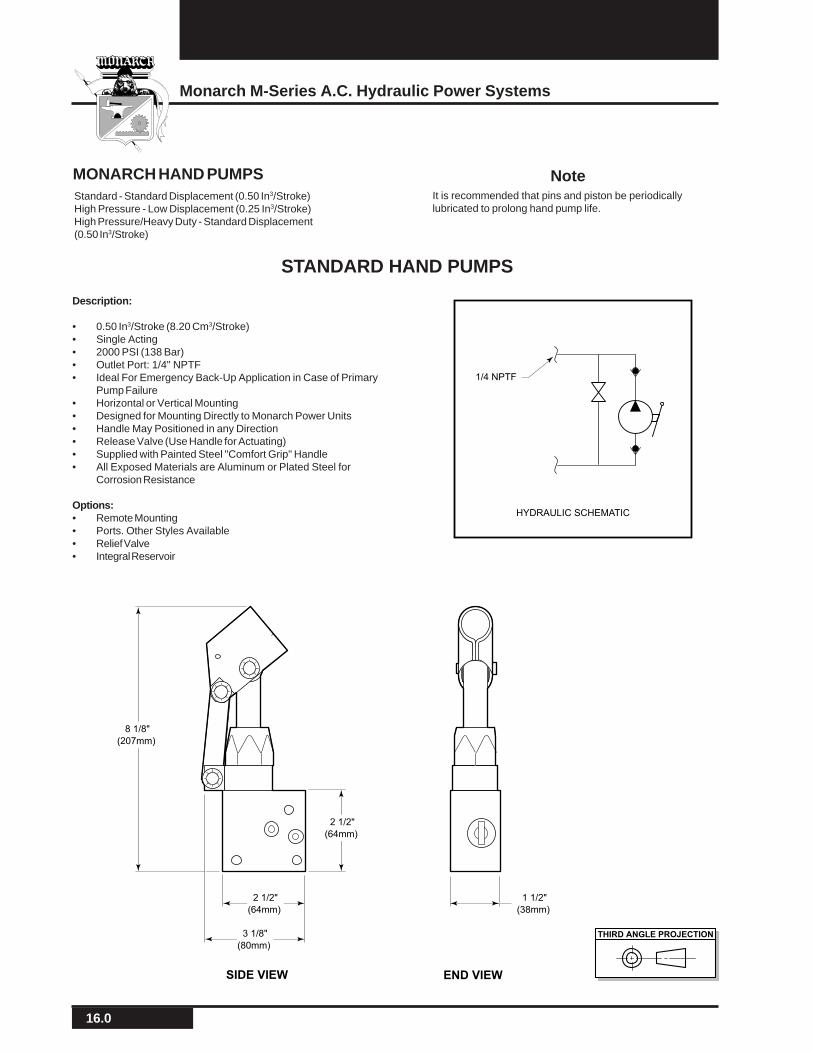
Description:
• 0.50 In3/Stroke (8.20 Cm3/Stroke)• Single Acting• 2000 PSI (138 Bar)• Outlet Port: 1/4" NPTF• Ideal For Emergency Back-Up Application in Case of Primary
Pump Failure• Horizontal or Vertical Mounting• Designed for Mounting Directly to Monarch Power Units• Handle May Positioned in any Direction• Release Valve (Use Handle for Actuating)• Supplied with Painted Steel "Comfort Grip" Handle• All Exposed Materials are Aluminum or Plated Steel for
Corrosion Resistance
Options:• Remote Mounting• Ports. Other Styles Available• Relief Valve• Integral Reservoir
MONARCH HAND PUMPS
STANDARD HAND PUMPS
Standard - Standard Displacement (0.50 In3/Stroke)High Pressure - Low Displacement (0.25 In3/Stroke)High Pressure/Heavy Duty - Standard Displacement(0.50 In3/Stroke)
It is recommended that pins and piston be periodicallylubricated to prolong hand pump life.
Note
8 1/8"
(207mm)
2 1/2"
(64mm)
2 1/2"
(64mm)
3 1/8"
(80mm)
SIDE VIEW
1 1/2"
(38mm)
END VIEW
1/4 NPTF
HYDRAULIC SCHEMATIC
THIRD ANGLE PROJECTION
17.0
Monarch Hydraulics, Inc.
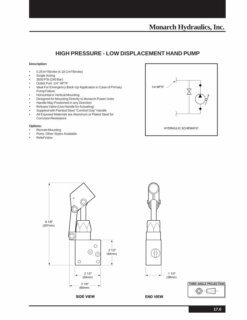
Description:
• 0.25 In3/Stroke (4.10 Cm3/Stroke)• Single Acting• 3500 PSI (240 Bar)• Outlet Port: 1/4" NPTF• Ideal For Emergency Back-Up Application in Case of Primary
Pump Failure• Horizontal or Vertical Mounting• Designed for Mounting Directly to Monarch Power Units• Handle May Positioned in any Direction• Release Valve (Use Handle for Actuating)• Supplied with Painted Steel "Comfort Grip" Handle• All Exposed Materials are Aluminum or Plated Steel for
Corrosion Resistance
Options:• Remote Mounting• Ports. Other Styles Available• Relief Valve
HIGH PRESSURE - LOW DISPLACEMENT HAND PUMP
1/4 NPTF
HYDRAULIC SCHEMATIC
THIRD ANGLE PROJECTION
8 1/8"
(207mm)
2 1/2"
(64mm)
2 1/2"
(64mm)
3 1/8"
(80mm)
SIDE VIEW
1 1/2"
(38mm)
END VIEW
18.0
Monarch M-Series A.C. Hydraulic Power Systems
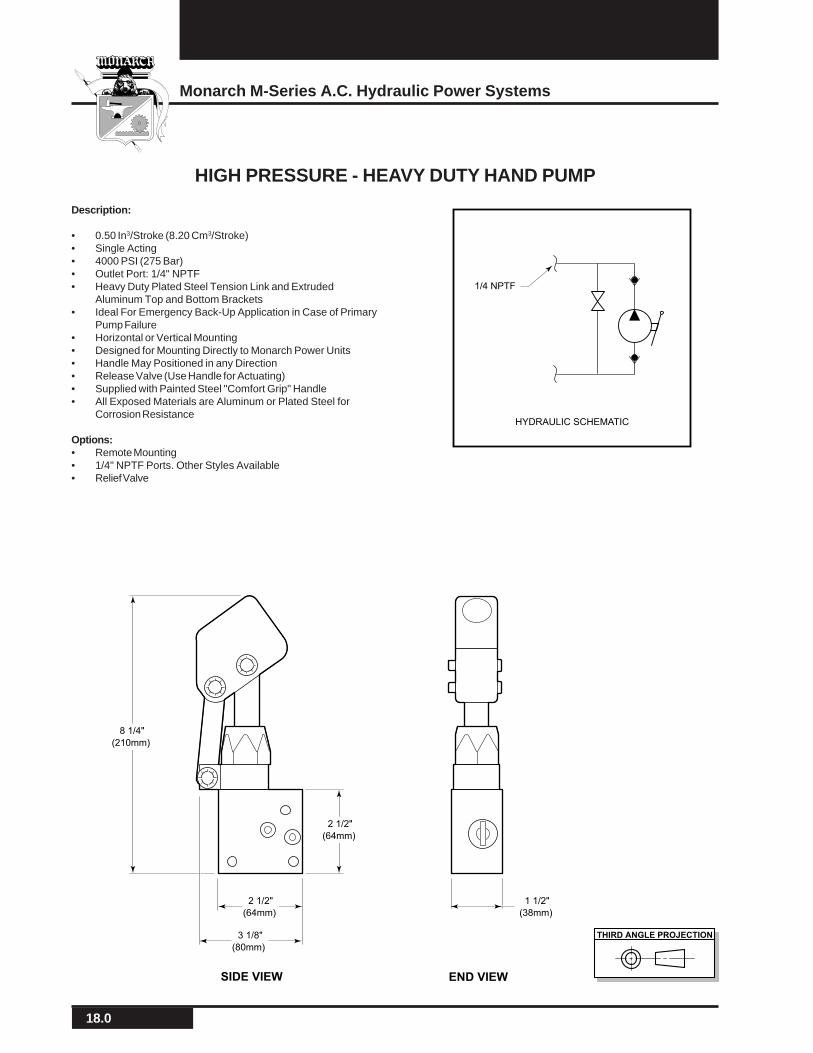
Description:
• 0.50 In3/Stroke (8.20 Cm3/Stroke)• Single Acting• 4000 PSI (275 Bar)• Outlet Port: 1/4" NPTF• Heavy Duty Plated Steel Tension Link and Extruded
Aluminum Top and Bottom Brackets• Ideal For Emergency Back-Up Application in Case of Primary
Pump Failure• Horizontal or Vertical Mounting• Designed for Mounting Directly to Monarch Power Units• Handle May Positioned in any Direction• Release Valve (Use Handle for Actuating)• Supplied with Painted Steel "Comfort Grip" Handle• All Exposed Materials are Aluminum or Plated Steel for
Corrosion Resistance
Options:• Remote Mounting• 1/4" NPTF Ports. Other Styles Available• Relief Valve
HIGH PRESSURE - HEAVY DUTY HAND PUMP
1/4 NPTF
HYDRAULIC SCHEMATIC
THIRD ANGLE PROJECTION
8 1/4"
(210mm)
2 1/2"
(64mm)
2 1/2"
(64mm)
3 1/8"
(80mm)
SIDE VIEW
1 1/2"
(38mm)
END VIEW
19.0
Monarch Hydraulics, Inc.
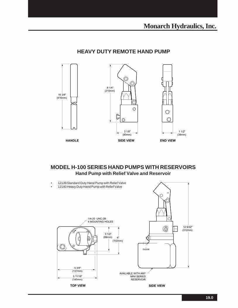
8 1/4"
(210mm)
16 3/8"
(416mm)
3 1/8"
(80mm)
SIDE VIEWHANDLE
1 1/2"
(38mm)
END VIEW
FILL LINE
12 9/32"
(312mm)
4"
(102mm)
3 1/2"
(89mm)
SIDE VIEW
5 11/16"
(145mm)
5 3/8"
(137mm)
TOP VIEW
AVAILABLE WITH ANY
MINI SERIES
RESERVOIR
1/4-20 UNC-2B
4 MOUNTING HOLES
HEAVY DUTY REMOTE HAND PUMP
MODEL H-100 SERIES HAND PUMPS WITH RESERVOIRSHand Pump with Relief Valve and Reservoir
• 12139 Standard Duty Hand Pump with Relief Valve• 12140 Heavy Duty Hand Pump with Relief Valve

20.0
Monarch M-Series A.C. Hydraulic Power Systems
NOTES:
21.0
Monarch Hydraulics, Inc.
Monarch A.C. Hydraulic Power Systems
22.0
Monarch M-Series A.C. Hydraulic Power Systems
PUMP MOTOR CAPACITOR MOUNTINGPOSITION
OPTIONALACCESSORIES
Ref. Page9.0
Ref. Page9.0
Ref. Page9.0
Ref. Page15.0
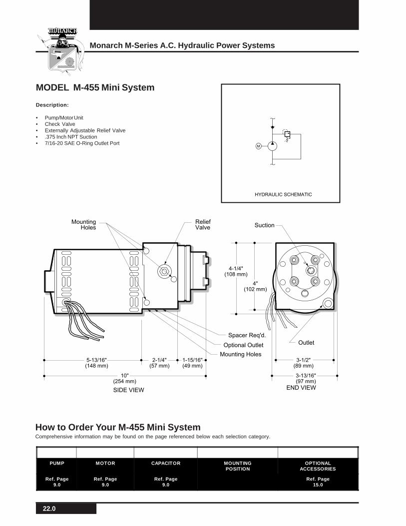
MODEL M-455 Mini System
Description:
• Pump/Motor Unit• Check Valve• Externally Adjustable Relief Valve• .375 Inch NPT Suction• 7/16-20 SAE O-Ring Outlet Port
M
HYDRAULIC SCHEMATIC
How to Order Your M-455 Mini SystemComprehensive information may be found on the page referenced below each selection category.
Optional Outlet Outlet
ReliefValve Suction
MountingHoles
Mounting Holes
END VIEWSIDE VIEW
Spacer Req'd.
10"(254 mm)
5-13/16"(148 mm)
2-1/4"(57 mm)
1-15/16"(49 mm)
3-1/2"(89 mm)
3-13/16"(97 mm)
4-1/4"(108 mm)
4"(102 mm)
23.0
Monarch Hydraulics, Inc.
M
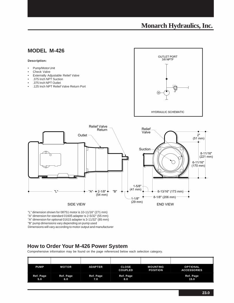
OUTLET PORT
3/8 NPTF
HYDRAULIC SCHEMATIC
Outlet
ReliefValve
Relief ValveReturn
Suction
SIDE VIEW END VIEW
"L" "A" 2-1/8"(54 mm)
"B" 6-13/16" (173 mm)
8-1/8" (206 mm)
1-5/8"(41 mm)
2"(51 mm)
6-11/16"(170 mm)
8-11/16"(221 mm)
1-1/8"(29 mm)
MODEL M-426
Description:
• Pump/Motor Unit• Check Valve• Externally Adjustable Relief Valve• .375 Inch NPT Suction• .375 Inch NPT Outlet• .125 Inch NPT Relief Valve Return Port
"L" dimension shown for 08751 motor is 10-11/16" (271 mm)"A" dimension for standard 01605 adapter is 2-5/32" (55 mm)"A" dimension for optional 01615 adapter is 3-11/32" (85 mm)"B" pump dimensions vary depending on pump usedDimensions will vary according to motor output and manufacturer
How to Order Your M-426 Power SystemComprehensive information may be found on the page referenced below each selection category.
PUMP MOTOR ADAPTER CLOSECOUPLED
MOUNTINGPOSITION
OPTIONALACCESSORIES
Ref. Page5.0
Ref. Page6.0
Ref. Page7.0
Ref. Page8.0
Ref. Page15.0

24.0
Monarch M-Series A.C. Hydraulic Power Systems
How to Order Your M-454 Mini SystemComprehensive information may be found on the page referenced below each selection category.
MODEL M-454 Mini System
Description:
• Pump/Motor/Reservoir Unit• Externally Adjustable Relief Valve• 7/16-20 SAE O-Ring Outlet Port, 3/8" NPT Return• Horizontal Mounting Standard• Vertical Mounting (Motor Up) Optional M
HYDRAULIC SCHEMATIC
Optional OutletOutlet
ReliefValve
MountingHoles
Mounting Holes
END VIEWSIDE VIEW
14-17/32"369 mm)
5-13/16"(148 mm)
2-1/4"(57 mm)
6-15/32"(164 mm)
3-1/2" (89mm)
3-13/16" (97mm)
Spacer Req'd.
4-1/4"(108 mm)
4"(102 mm)
FILL LINE
MONARCH
ReturnPort
PUMP MOTOR CAPACITOR RESERVOIR MOUNTINGPOSITION
OPTIONALACCESSORIES
Ref. Page9.0
Ref. Page9.0
Ref. Page9.0
Ref. Page11.0
Ref. Page15.0
25.0
Monarch Hydraulics, Inc.
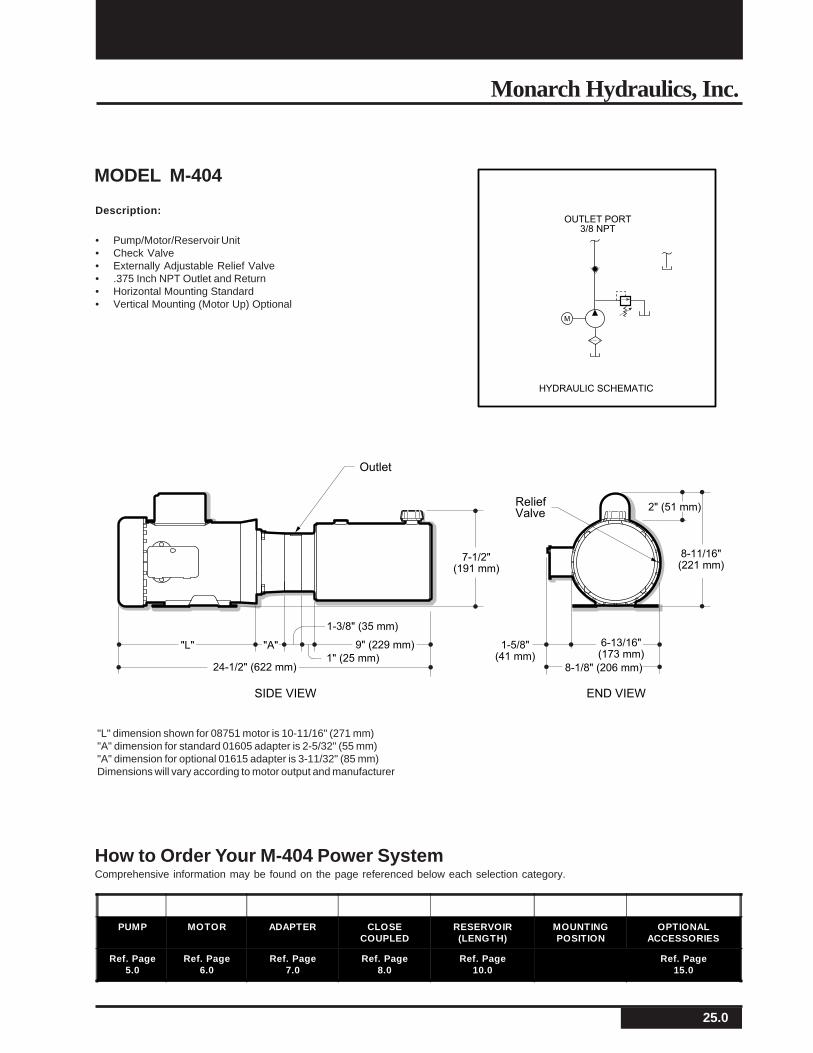
MODEL M-404
Description:
• Pump/Motor/Reservoir Unit• Check Valve• Externally Adjustable Relief Valve• .375 Inch NPT Outlet and Return• Horizontal Mounting Standard• Vertical Mounting (Motor Up) Optional
"L" dimension shown for 08751 motor is 10-11/16" (271 mm)"A" dimension for standard 01605 adapter is 2-5/32" (55 mm)"A" dimension for optional 01615 adapter is 3-11/32" (85 mm)Dimensions will vary according to motor output and manufacturer
M
OUTLET PORT
3/8 NPT
HYDRAULIC SCHEMATIC
Outlet
ReliefValve
END VIEWSIDE VIEW
7-1/2"(191 mm)
"L" "A"
24-1/2" (622 mm)
1-5/8"(41 mm)
6-13/16"(173 mm)
8-1/8" (206 mm)1" (25 mm)
9" (229 mm)
1-3/8" (35 mm)
8-11/16"(221 mm)
2" (51 mm)
How to Order Your M-404 Power SystemComprehensive information may be found on the page referenced below each selection category.
PUMP MOTOR ADAPTER CLOSECOUPLED
RESERVOIR(LENGTH)
MOUNTINGPOSITION
OPTIONALACCESSORIES
Ref. Page5.0
Ref. Page6.0
Ref. Page7.0
Ref. Page8.0
Ref. Page10.0
Ref. Page15.0
26.0
Monarch M-Series A.C. Hydraulic Power Systems
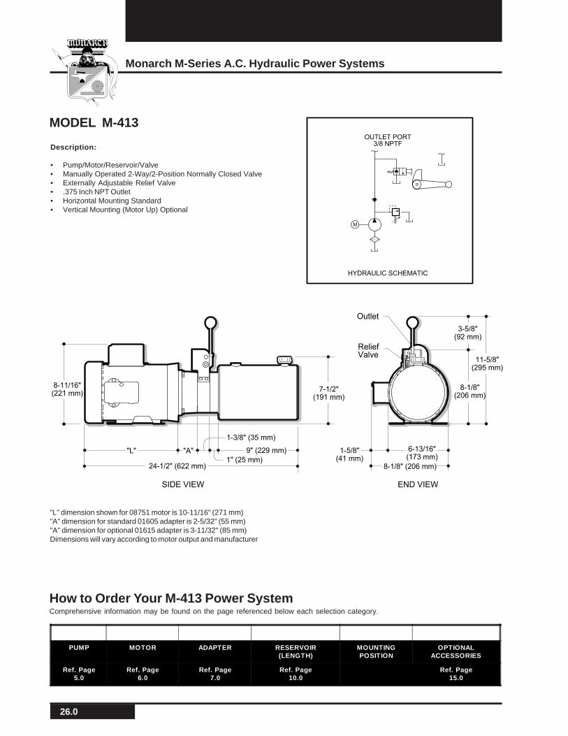
MODEL M-413
Description:
• Pump/Motor/Reservoir/Valve• Manually Operated 2-Way/2-Position Normally Closed Valve• Externally Adjustable Relief Valve• .375 Inch NPT Outlet• Horizontal Mounting Standard• Vertical Mounting (Motor Up) Optional
"L" dimension shown for 08751 motor is 10-11/16" (271 mm)"A" dimension for standard 01605 adapter is 2-5/32" (55 mm)"A" dimension for optional 01615 adapter is 3-11/32" (85 mm)Dimensions will vary according to motor output and manufacturer
Outlet
ReliefValve
END VIEWSIDE VIEW
11-5/8"(295 mm)
8-11/16"(221 mm)
8-1/8"(206 mm)
3-5/8"(92 mm)
7-1/2"(191 mm)
1-5/8"(41 mm)
6-13/16"(173 mm)
8-1/8" (206 mm)
"L" "A"
24-1/2" (622 mm)1" (25 mm)
9" (229 mm)
1-3/8" (35 mm)
M
OUTLET PORT
3/8 NPTF
HYDRAULIC SCHEMATIC
How to Order Your M-413 Power SystemComprehensive information may be found on the page referenced below each selection category.
PUMP MOTOR ADAPTER RESERVOIR(LENGTH)
MOUNTINGPOSITION
OPTIONALACCESSORIES
Ref. Page5.0
Ref. Page6.0
Ref. Page7.0
Ref. Page10.0
Ref. Page15.0

27.0
Monarch Hydraulics, Inc.
Description:
• Pump/Motor/Reservoir/Valve Unit• 3-Way Manually Operated Valve• Externally Adjustable Relief Valve• #6 SAE• Vertical Mounting Standard (Motor Up)• Snap Action Push Button Start Switch
in Motor• Kill Switch in Motor (Optional)• Cord and Plug from Motor (Optional)
MODEL M-4509
"L" dimension shown for 08751 motor is 10-11/16" (271 mm)"A" dimension for standard 01605 adapter is 2-5/32" (55 mm)"A" dimension for optional 01615 adapter is 3-11/32" (85 mm)Dimensions will vary according to motor output and manufacturer
M-413-SHYDRAULIC SCHEMATIC
Outlet Port#6 SAE (9/16-18)
M
L1
L2
OutletReliefValve
END VIEWSIDE VIEW
7-1/2"(191 mm)
"L" "A"
10-1/2"(267 mm)
24-1/2" (622 mm)
8-11/16"(221 mm)
6-13/16"(173 mm)
8-1/8"(206 mm)
7-1/4"(184 mm)
3-3/8"(86 mm)
1" (25 mm)
9" (229 mm)
1-3/8" (35 mm)
1-5/8"(41 mm)
PUMP MOTOR ADAPTER RESERVOIR(LENGTH)
MOUNTINGPOSITION
VALVES OPTIONALACCESSORIES
Ref. Page5.0
Ref. Page6.0
Ref. Page7.0
Ref. Page10.0
Ref. Page13.0
Ref. Page15.0
How to Order Your M-4509 Power SystemComprehensive information may be found on the page referenced below each selection category.
28.0
Monarch M-Series A.C. Hydraulic Power Systems
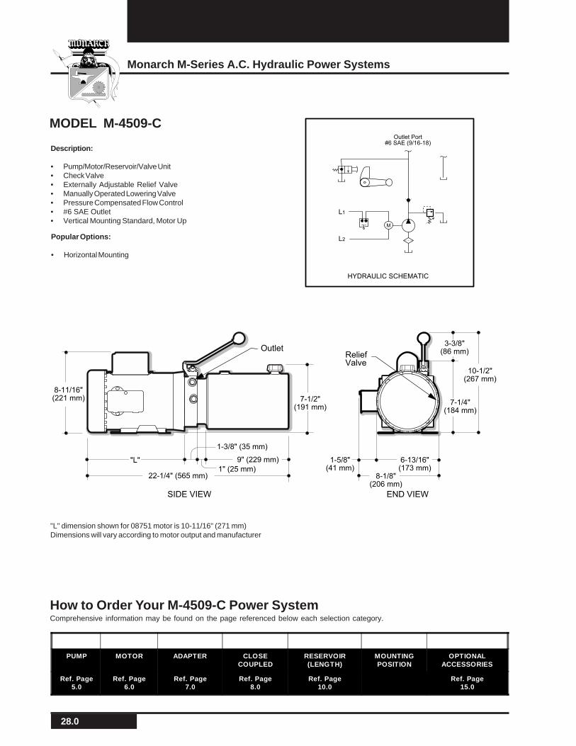
Description:
• Pump/Motor/Reservoir/Valve Unit• Check Valve• Externally Adjustable Relief Valve• Manually Operated Lowering Valve• Pressure Compensated Flow Control• #6 SAE Outlet• Vertical Mounting Standard, Motor Up
MODEL M-4509-C
"L" dimension shown for 08751 motor is 10-11/16" (271 mm)Dimensions will vary according to motor output and manufacturer
PUMP MOTOR ADAPTER CLOSECOUPLED
RESERVOIR(LENGTH)
MOUNTINGPOSITION
OPTIONALACCESSORIES
Ref. Page5.0
Ref. Page6.0
Ref. Page7.0
Ref. Page8.0
Ref. Page10.0
Ref. Page15.0
How to Order Your M-4509-C Power SystemComprehensive information may be found on the page referenced below each selection category.
Popular Options:
• Horizontal Mounting
HYDRAULIC SCHEMATIC
Outlet Port#6 SAE (9/16-18)
M
L1
L2
OutletReliefValve
END VIEWSIDE VIEW
7-1/2"(191 mm)
"L"
10-1/2"(267 mm)
22-1/4" (565 mm)
8-11/16"(221 mm)
6-13/16"(173 mm)
8-1/8"(206 mm)
7-1/4"(184 mm)
3-3/8"(86 mm)
1" (25 mm)
9" (229 mm)
1-3/8" (35 mm)
1-5/8"(41 mm)
29.0
Monarch Hydraulics, Inc.
OUTLET PORT
"B""A"
"T""P"
HYDRAULIC SCHEMATIC
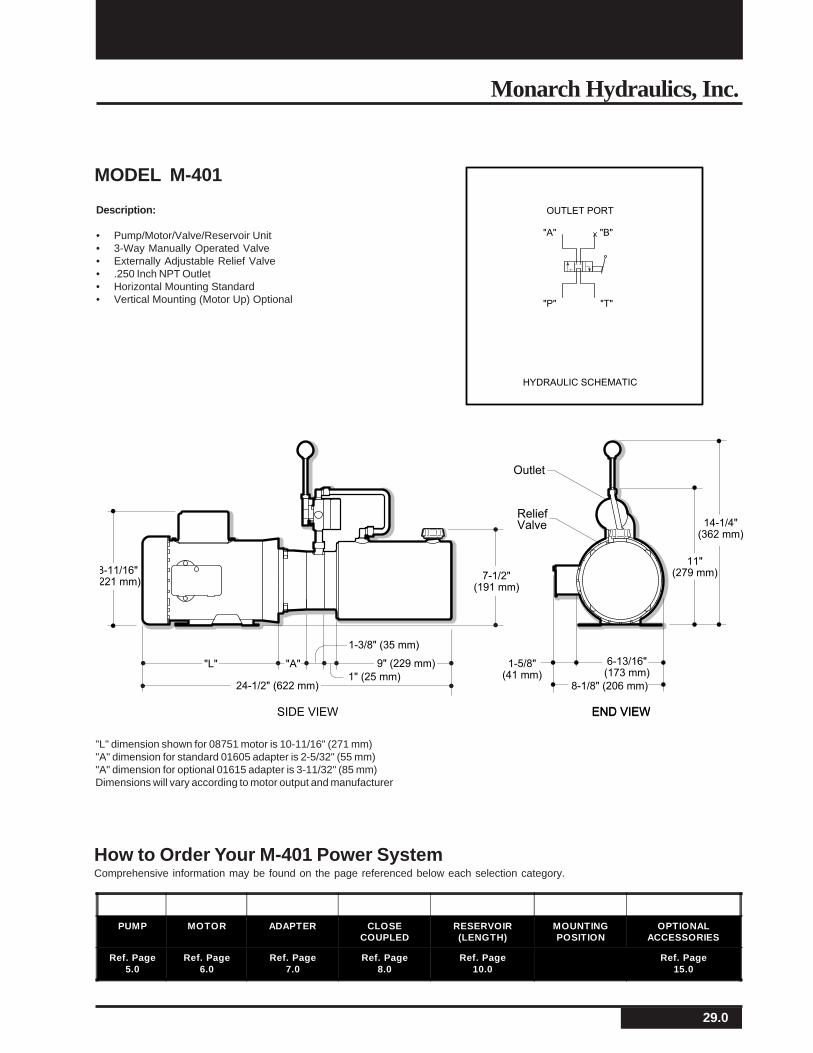
Description:
• Pump/Motor/Valve/Reservoir Unit• 3-Way Manually Operated Valve• Externally Adjustable Relief Valve• .250 Inch NPT Outlet• Horizontal Mounting Standard• Vertical Mounting (Motor Up) Optional
MODEL M-401
"L" dimension shown for 08751 motor is 10-11/16" (271 mm)"A" dimension for standard 01605 adapter is 2-5/32" (55 mm)"A" dimension for optional 01615 adapter is 3-11/32" (85 mm)Dimensions will vary according to motor output and manufacturer
Outlet
ReliefValve
END VIEWSIDE VIEW
14-1/4"(362 mm)
1-5/8"
11"(279 mm)
6-13/16"1-5/8"(41 mm)
6-13/16"(173 mm)
8-1/8" (206 mm)
8-11/16"221 mm)
"L" "A"
24-1/2" (622 mm)1" (25 mm)
9" (229 mm)
1-3/8" (35 mm)
7-1/2"(191 mm)
END VIEW
How to Order Your M-401 Power SystemComprehensive information may be found on the page referenced below each selection category.
PUMP MOTOR ADAPTER CLOSECOUPLED
RESERVOIR(LENGTH)
MOUNTINGPOSITION
OPTIONALACCESSORIES
Ref. Page5.0
Ref. Page6.0
Ref. Page7.0
Ref. Page8.0
Ref. Page10.0
Ref. Page15.0
30.0
Monarch M-Series A.C. Hydraulic Power Systems
M
1/4 NPTF
HYDRAULIC SCHEMATIC
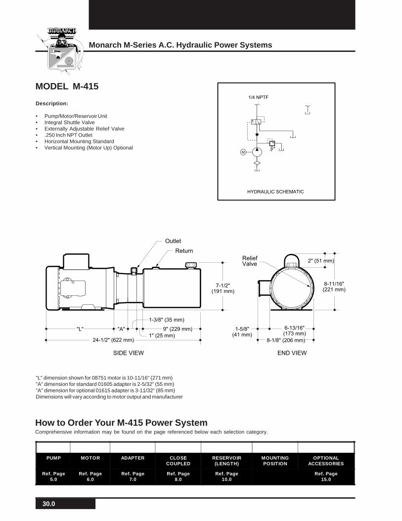
MODEL M-415
Description:
• Pump/Motor/Reservoir Unit• Integral Shuttle Valve• Externally Adjustable Relief Valve• .250 Inch NPT Outlet• Horizontal Mounting Standard• Vertical Mounting (Motor Up) Optional
"L" dimension shown for 08751 motor is 10-11/16" (271 mm)"A" dimension for standard 01605 adapter is 2-5/32" (55 mm)"A" dimension for optional 01615 adapter is 3-11/32" (85 mm)Dimensions will vary according to motor output and manufacturer
END VIEWSIDE VIEW
Outlet
Return
ReliefValve
7-1/2"(191 mm)
"L" "A"
24-1/2" (622 mm)
1-5/8"(41 mm)
6-13/16"(173 mm)
8-1/8" (206 mm)1" (25 mm)
9" (229 mm)
1-3/8" (35 mm)
8-11/16"(221 mm)
2" (51 mm)
How to Order Your M-415 Power SystemComprehensive information may be found on the page referenced below each selection category.
PUMP MOTOR ADAPTER CLOSECOUPLED
RESERVOIR(LENGTH)
MOUNTINGPOSITION
OPTIONALACCESSORIES
Ref. Page5.0
Ref. Page6.0
Ref. Page7.0
Ref. Page8.0
Ref. Page10.0
Ref. Page15.0
31.0
Monarch Hydraulics, Inc.
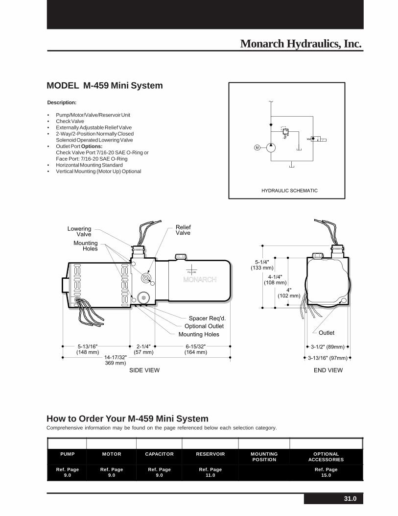
MODEL M-459 Mini System
Description:
• Pump/Motor/Valve/Reservoir Unit• Check Valve• Externally Adjustable Relief Valve• 2-Way/2-Position Normally Closed
Solenoid Operated Lowering Valve• Outlet Port Options:
Check Valve Port 7/16-20 SAE O-Ring orFace Port: 7/16-20 SAE O-Ring
• Horizontal Mounting Standard• Vertical Mounting (Motor Up) Optional
LoweringValve
Optional OutletOutlet
ReliefValve
MountingHoles
Mounting Holes
END VIEWSIDE VIEW
Spacer Req'd.
5-1/4"(133 mm)
14-17/32"369 mm)
5-13/16"(148 mm)
2-1/4"(57 mm)
6-15/32"(164 mm)
3-1/2" (89mm)
3-13/16" (97mm)
4-1/4"(108 mm)
4"(102 mm)
FILL LINE
MONARCH
M
HYDRAULIC SCHEMATIC
PUMP MOTOR CAPACITOR RESERVOIR MOUNTINGPOSITION
OPTIONALACCESSORIES
Ref. Page9.0
Ref. Page9.0
Ref. Page9.0
Ref. Page11.0
Ref. Page15.0
How to Order Your M-459 Mini SystemComprehensive information may be found on the page referenced below each selection category.
32.0
Monarch M-Series A.C. Hydraulic Power Systems
How to Order Your M-458 Mini SystemComprehensive information may be found on the page referenced below each selection category.
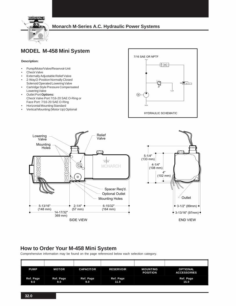
Description:
• Pump/Motor/Valve/Reservoir Unit• Check Valve• Externally Adjustable Relief Valve• 2-Way/2-Position Normally Closed
Solenoid Operated Lowering Valve• Cartridge Style Pressure Compensated
Lowering Valve• Outlet Port Options:
Check Valve Port 7/16-20 SAE O-Ring orFace Port: 7/16-20 SAE O-Ring
• Horizontal Mounting Standard• Vertical Mounting (Motor Up) Optional
MODEL M-458 Mini System
LoweringValve
Optional OutletOutlet
ReliefValve
MountingHoles
Mounting Holes
END VIEWSIDE VIEW
Spacer Req'd.
5-1/4"(133 mm)
14-17/32"369 mm)
5-13/16"(148 mm)
2-1/4"(57 mm)
6-15/32"(164 mm)
3-1/2" (89mm)
3-13/16" (97mm)
4-1/4"(108 mm)
4"(102 mm)
FILL LINE
MONARCH
7/16 SAE OR NPTF
M
HYDRAULIC SCHEMATIC
PUMP MOTOR CAPACITOR RESERVOIR MOUNTINGPOSITION
OPTIONALACCESSORIES
Ref. Page9.0
Ref. Page9.0
Ref. Page9.0
Ref. Page11.0
Ref. Page15.0
33.0
Monarch Hydraulics, Inc.
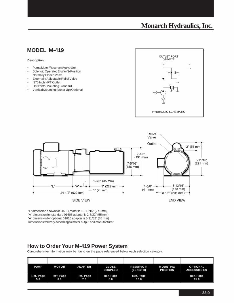
MODEL M-419
Description:
• Pump/Motor/Reservoir/Valve Unit• Solenoid Operated 2-Way/2-Position
Normally Closed Valve• Externally Adjustable Relief Valve• .375 Inch NPT Outlet• Horizontal Mounting Standard• Vertical Mounting (Motor Up) Optional
"L" dimension shown for 08751 motor is 10-11/16" (271 mm)"A" dimension for standard 01605 adapter is 2-5/32" (55 mm)"A" dimension for optional 01615 adapter is 3-11/32" (85 mm)Dimensions will vary according to motor output and manufacturer
Outlet
ReliefValve
END VIEWSIDE VIEW
7-1/2"(191 mm)
"L" "A"
24-1/2" (622 mm)
1-5/8"(41 mm)
6-13/16"(173 mm)
8-1/8" (206 mm)1" (25 mm)
9" (229 mm)
1-3/8" (35 mm)
8-11/16"(221 mm)
2" (51 mm)
7-5/16"(186 mm)
M
OUTLET PORT
3/8 NPTF
HYDRAULIC SCHEMATIC
How to Order Your M-419 Power SystemComprehensive information may be found on the page referenced below each selection category.
PUMP MOTOR ADAPTER CLOSECOUPLED
RESERVOIR(LENGTH)
MOUNTINGPOSITION
OPTIONALACCESSORIES
Ref. Page5.0
Ref. Page6.0
Ref. Page7.0
Ref. Page8.0
Ref. Page10.0
Ref. Page15.0

34.0
Monarch M-Series A.C. Hydraulic Power Systems
Description:
• Pump/Motor/Reservoir/Valve Unit• Check Valve• Externally Adjustable Relief Valve• 2 Way/2 Position Normally Closed Cartridge Valve• #6 SAE Outlet• Horizontal Mounting Standard
MODEL M-4519-C
"L" dimension shown for 08751 motor is 10-11/16" (271 mm)Dimensions will vary according to motor output and manufacturer
PUMP MOTOR ADAPTER CLOSECOUPLED
RESERVOIR(LENGTH)
MOUNTINGPOSITION
OPTIONALACCESSORIES
Ref. Page5.0
Ref. Page6.0
Ref. Page7.0
Ref. Page8.0
Ref. Page10.0
Ref. Page15.0
How to Order Your M-4519-C Power SystemComprehensive information may be found on the page referenced below each selection category.
Popular Options:
• Vertical Mounting, Motor Up• Pressure Compensated Cartridge Style On Lowering Circuit• Manual Override
M
HYDRAULIC SCHEMATIC
ReliefValve
END VIEWSIDE VIEW
7-1/2"(191 mm)
"L"
8-11/16"(221 mm)
22-1/4" (565 mm)
6-13/16"(173 mm)
8-1/8"(206 mm)
2" (52 mm)
1" (25 mm)
9" (229 mm)
1-3/8" (35 mm)
1-5/8"(41 mm)

35.0
Monarch Hydraulics, Inc.
Description:
• Pump/Motor/Reservoir/Valve Unit• Solenoid Operated 2-Way/2-Position Normally Closed Valve
and Solenoid Operated 2-Way/2-Position Normally Open Valve
• Externally Adjustable Relief Valve• .375 Inch NPT Outlet• Horizontal Mounting Standard• Vertical Mounting (Motor Up) Optional
MODEL M-403
M
OUTLET PORT
3/8 NPT
HYDRAULIC SCHEMATIC
"L" dimension shown for 08751 motor is 10-11/16" (271 mm)"A" dimension for standard 01605 adapter is 2-5/32" (55 mm)"A" dimension for optional 01615 adapter is 3-11/32" (85 mm)Dimensions will vary according to motor output and manufacturer
ReliefValve
END VIEWSIDE VIEW
7-1/2"(191 mm)
"L" "A"
24-1/2" (622 mm)
1-5/8"(41 mm)
6-13/16"(173 mm)
8-1/8" (206 mm)1" (25 mm)
9" (229 mm)
1-3/8" (35 mm)
PUMP MOTOR ADAPTER RESERVOIR(LENGTH)
MOUNTINGPOSITION
OPTIONALACCESSORIES
Ref. Page5.0
Ref. Page6.0
Ref. Page7.0
Ref. Page10.0
Ref. Page15.0
How to Order Your M-403 Power SystemComprehensive information may be found on the page referenced below each selection category.
36.0
Monarch M-Series A.C. Hydraulic Power Systems
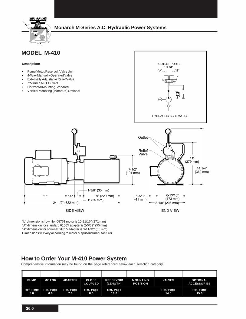
Description:
• Pump/Motor/Reservoir/Valve Unit• 4-Way Manually Operated Valve• Externally Adjustable Relief Valve• .250 Inch NPT Outlets• Horizontal Mounting Standard• Vertical Mounting (Motor Up) Optional
MODEL M-410
M
OUTLET PORTS
1/4 NPT
"B""A"
HYDRAULIC SCHEMATIC
Outlet
ReliefValve
END VIEWSIDE VIEW
7-1/2"(191 mm)
"L" "A"
24-1/2" (622 mm)
1-5/8"(41 mm)
6-13/16"(173 mm)
8-1/8" (206 mm)1" (25 mm)
9" (229 mm)
1-3/8" (35 mm)
14 1/4"(362 mm)
11"(279 mm)
"L" dimension shown for 08751 motor is 10-11/16" (271 mm)"A" dimension for standard 01605 adapter is 2-5/32" (55 mm)"A" dimension for optional 01615 adapter is 3-11/32" (85 mm)Dimensions will vary according to motor output and manufacturer
How to Order Your M-410 Power SystemComprehensive information may be found on the page referenced below each selection category.
PUMP MOTOR ADAPTER CLOSECOUPLED
RESERVOIR(LENGTH)
MOUNTINGPOSITION
VALVES OPTIONALACCESSORIES
Ref. Page5.0
Ref. Page6.0
Ref. Page7.0
Ref. Page8.0
Ref. Page10.0
Ref. Page14.0
Ref. Page15.0
37.0
Monarch Hydraulics, Inc.
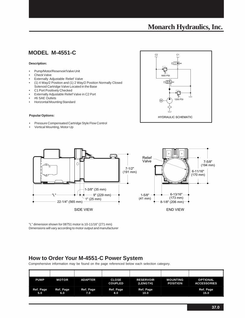
Description:
• Pump/Motor/Reservoir/Valve Unit• Check Valve• Externally Adjustable Relief Valve• (1) 4 Way/2 Position and (1) 2 Way/2 Position Normally Closed
Solenoid Cartridge Valve Located in the Base• C1 Port Positively Checked• Externally Adjustable Relief Valve in C2 Port• #6 SAE Outlets• Horizontal Mounting Standard
MODEL M-4551-C
"L" dimension shown for 08751 motor is 10-11/16" (271 mm)Dimensions will vary according to motor output and manufacturer
PUMP MOTOR ADAPTER CLOSECOUPLED
RESERVOIR(LENGTH)
MOUNTINGPOSITION
OPTIONALACCESSORIES
Ref. Page5.0
Ref. Page6.0
Ref. Page7.0
Ref. Page8.0
Ref. Page10.0
Ref. Page15.0
How to Order Your M-4551-C Power SystemComprehensive information may be found on the page referenced below each selection category.
Popular Options:
• Pressure Compensated Cartridge Style Flow Control• Vertical Mounting, Motor Up
M
HYDRAULIC SCHEMATIC
1200 PSI
C2 C1
1800 PSI
ReliefValve
END VIEWSIDE VIEW
"L"
7-5/8"(194 mm)
7-1/2"(191 mm)
22-1/4" (565 mm)
1-5/8"(41 mm)
6-13/16"(173 mm)
8-1/8" (206 mm)1" (25 mm)
9" (229 mm)
1-3/8" (35 mm)
6-11/16"(170 mm)
38.0
Monarch M-Series A.C. Hydraulic Power Systems
PUMP MOTOR CAPACITOR RESERVOIR MOUNTINGPOSITION
OPTIONALACCESSORIES
Ref. Page9.0
Ref. Page9.0
Ref. Page9.0
Ref. Page11.0
Ref. Page15.0
How to Order Your M-452 Mini SystemComprehensive information may be found on the page referenced below each selection category.
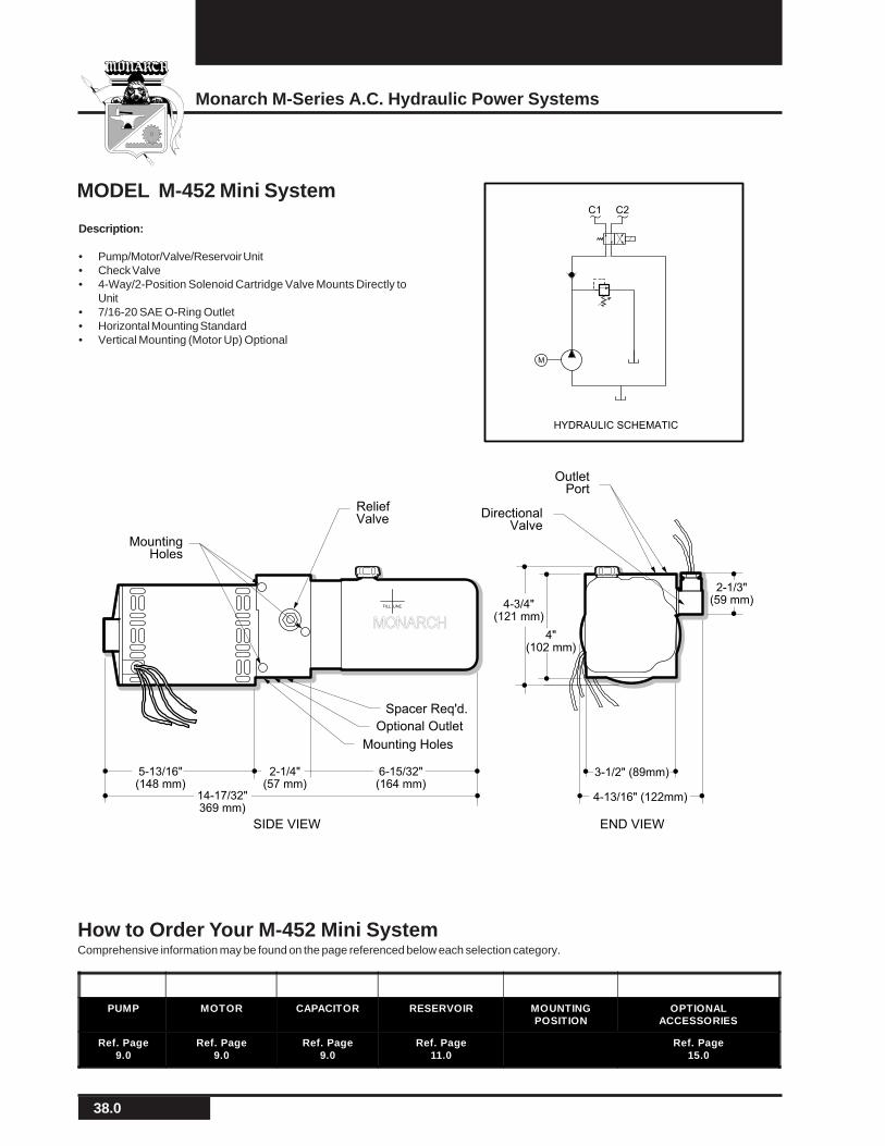
Description:
• Pump/Motor/Valve/Reservoir Unit• Check Valve• 4-Way/2-Position Solenoid Cartridge Valve Mounts Directly to
Unit• 7/16-20 SAE O-Ring Outlet• Horizontal Mounting Standard• Vertical Mounting (Motor Up) Optional
MODEL M-452 Mini System
Optional Outlet
ReliefValve
MountingHoles
Mounting Holes
END VIEWSIDE VIEW
Spacer Req'd.
2-1/3"(59 mm)4-3/4"
(121 mm)
14-17/32"369 mm)
5-13/16"(148 mm)
2-1/4"(57 mm)
6-15/32"(164 mm)
3-1/2" (89mm)
4-13/16" (122mm)
4"(102 mm)
FILL LINE
MONARCH
DirectionalValve
OutletPort
M
C1 C2
HYDRAULIC SCHEMATIC
39.0
Monarch Hydraulics, Inc.
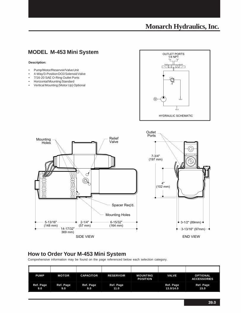
Description:
• Pump/Motor/Reservoir/Valve Unit• 4-Way/3-Position DO3 Solenoid Valve• 7/16-20 SAE O-Ring Outlet Ports• Horizontal Mounting Standard• Vertical Mounting (Motor Up) Optional
MODEL M-453 Mini System
How to Order Your M-453 Mini SystemComprehensive information may be found on the page referenced below each selection category.
ReliefValve
MountingHoles
Mounting Holes
END VIEWSIDE VIEW
Spacer Req'd.
7-3/4"(197 mm)
OutletPorts
14-17/32"369 mm)
5-13/16"(148 mm)
2-1/4"(57 mm)
6-15/32"(164 mm)
3-1/2" (89mm)
3-13/16" (97mm)
4"(102 mm)
M
OUTLET PORTS
1/4 NPT
HYDRAULIC SCHEMATIC
PUMP MOTOR CAPACITOR RESERVOIR MOUNTINGPOSITION
VALVE OPTIONALACCESSORIES
Ref. Page9.0
Ref. Page9.0
Ref. Page9.0
Ref. Page11.0
Ref. Page13.0/14.0
Ref. Page15.0
40.0
Monarch M-Series A.C. Hydraulic Power Systems
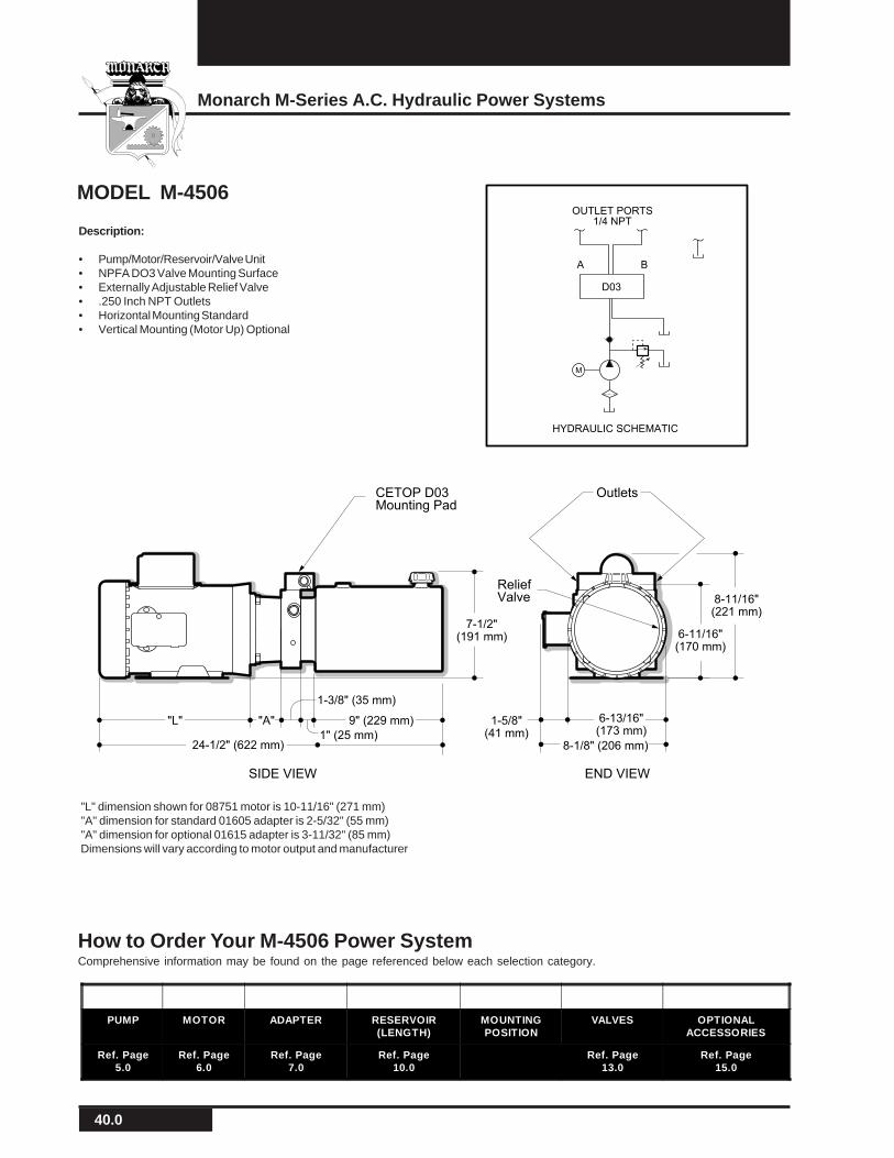
How to Order Your M-4506 Power SystemComprehensive information may be found on the page referenced below each selection category.
Description:
• Pump/Motor/Reservoir/Valve Unit• NPFA DO3 Valve Mounting Surface• Externally Adjustable Relief Valve• .250 Inch NPT Outlets• Horizontal Mounting Standard• Vertical Mounting (Motor Up) Optional
MODEL M-4506
"L" dimension shown for 08751 motor is 10-11/16" (271 mm)"A" dimension for standard 01605 adapter is 2-5/32" (55 mm)"A" dimension for optional 01615 adapter is 3-11/32" (85 mm)Dimensions will vary according to motor output and manufacturer
M
OUTLET PORTS
1/4 NPT
A B
HYDRAULIC SCHEMATIC
D03
CETOP D03Mounting Pad
Outlets
ReliefValve
END VIEWSIDE VIEW
"L" "A"
8-11/16"(221 mm)
7-1/2"(191 mm)
24-1/2" (622 mm)
1-5/8"(41 mm)
6-13/16"(173 mm)
8-1/8" (206 mm)1" (25 mm)
9" (229 mm)
1-3/8" (35 mm)
6-11/16"(170 mm)
PUMP MOTOR ADAPTER RESERVOIR(LENGTH)
MOUNTINGPOSITION
VALVES OPTIONALACCESSORIES
Ref. Page5.0
Ref. Page6.0
Ref. Page7.0
Ref. Page10.0
Ref. Page13.0
Ref. Page15.0
41.0
Monarch Hydraulics, Inc.
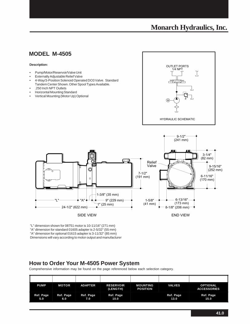
How to Order Your M-4505 Power SystemComprehensive information may be found on the page referenced below each selection category.
Description:
• Pump/Motor/Reservoir/Valve Unit• Externally Adjustable Relief Valve• 4-Way/3-Position Solenoid Operated DO3 Valve. Standard
Tandem Center Shown. Other Spool Types Available.• .250 Inch NPT Outlets• Horizontal Mounting Standard• Vertical Mounting (Motor Up) Optional
MODEL M-4505
"L" dimension shown for 08751 motor is 10-11/16" (271 mm)"A" dimension for standard 01605 adapter is 2-5/32" (55 mm)"A" dimension for optional 01615 adapter is 3-11/32" (85 mm)Dimensions will vary according to motor output and manufacturer
ReliefValve
END VIEWSIDE VIEW
"L" "A"
3-1/4"(82 mm)
9-15/16"(252 mm)
9-1/2"(241 mm)
7-1/2"(191 mm)
24-1/2" (622 mm)
1-5/8"(41 mm)
6-13/16"(173 mm)
8-1/8" (206 mm)1" (25 mm)
9" (229 mm)
1-3/8" (35 mm)
6-11/16"(170 mm)
M
OUTLET PORTS
1/4 NPT
HYDRAULIC SCHEMATIC
PUMP MOTOR ADAPTER RESERVOIR(LENGTH)
MOUNTINGPOSITION
VALVES OPTIONALACCESSORIES
Ref. Page5.0
Ref. Page6.0
Ref. Page7.0
Ref. Page10.0
Ref. Page13.0
Ref. Page15.0
42.0
Monarch M-Series A.C. Hydraulic Power Systems
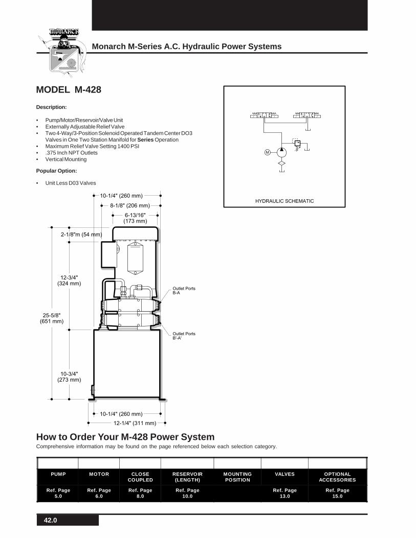
Description:
• Pump/Motor/Reservoir/Valve Unit• Externally Adjustable Relief Valve• Two 4-Way/3-Position Solenoid Operated Tandem Center DO3
Valves in One Two Station Manifold for Series Operation• Maximum Relief Valve Setting 1400 PSI• .375 Inch NPT Outlets• Vertical Mounting
MODEL M-428
M
HYDRAULIC SCHEMATIC
8-1/8" (206 mm)
10-1/4" (260 mm)
6-13/16"(173 mm)
12-3/4"(324 mm)
25-5/8"(651 mm)
10-1/4" (260 mm)
12-1/4" (311 mm)
Outlet PortsB-A
Outlet PortsB'-A'
2-1/8"m (54 mm)
10-3/4"(273 mm)
How to Order Your M-428 Power SystemComprehensive information may be found on the page referenced below each selection category.
PUMP MOTOR CLOSECOUPLED
RESERVOIR(LENGTH)
MOUNTINGPOSITION
VALVES OPTIONALACCESSORIES
Ref. Page5.0
Ref. Page6.0
Ref. Page8.0
Ref. Page10.0
Ref. Page13.0
Ref. Page15.0
Popular Option:
• Unit Less D03 Valves
43.0
Monarch Hydraulics, Inc.
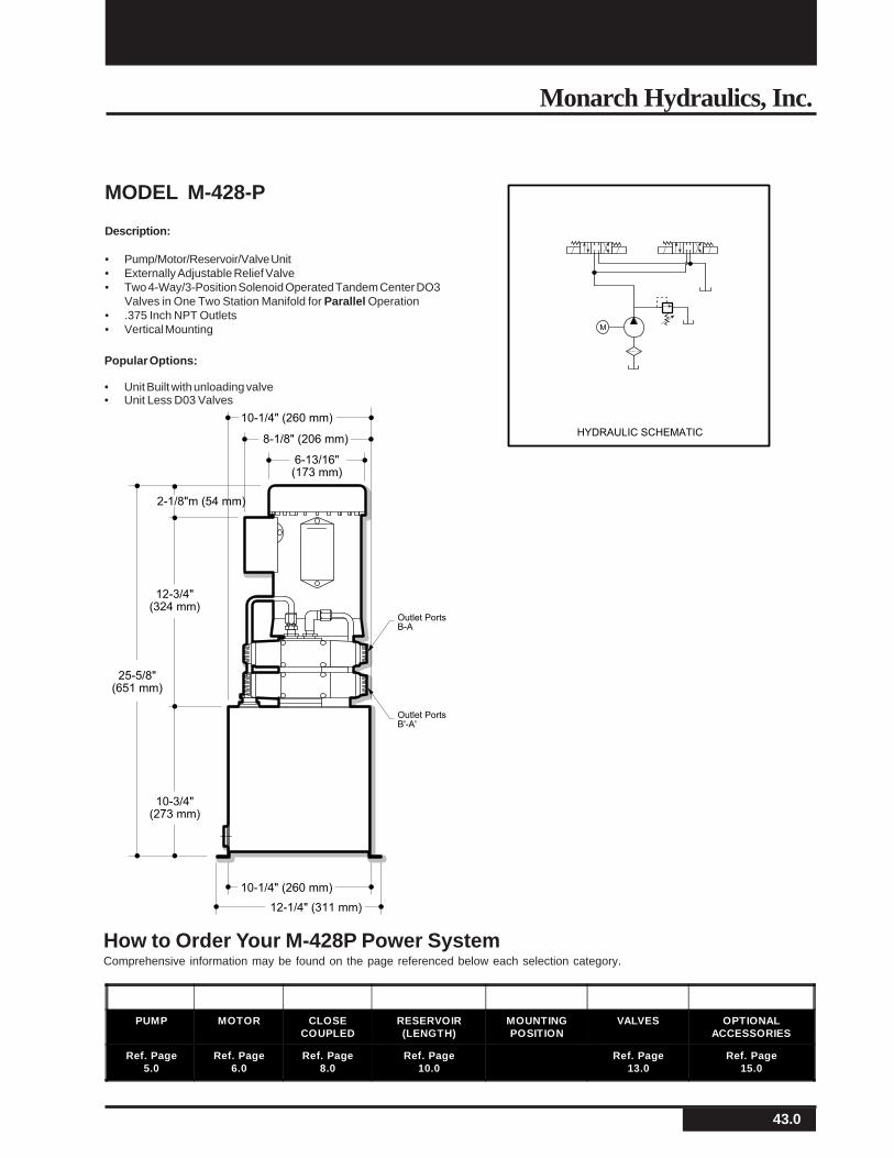
MODEL M-428-P
Description:
• Pump/Motor/Reservoir/Valve Unit• Externally Adjustable Relief Valve• Two 4-Way/3-Position Solenoid Operated Tandem Center DO3
Valves in One Two Station Manifold for Parallel Operation• .375 Inch NPT Outlets• Vertical Mounting
8-1/8" (206 mm)
10-1/4" (260 mm)
6-13/16"(173 mm)
12-3/4"(324 mm)
25-5/8"(651 mm)
10-1/4" (260 mm)
12-1/4" (311 mm)
Outlet PortsB-A
Outlet PortsB'-A'
2-1/8"m (54 mm)
10-3/4"(273 mm)
M
HYDRAULIC SCHEMATIC
How to Order Your M-428P Power SystemComprehensive information may be found on the page referenced below each selection category.
PUMP MOTOR CLOSECOUPLED
RESERVOIR(LENGTH)
MOUNTINGPOSITION
VALVES OPTIONALACCESSORIES
Ref. Page5.0
Ref. Page6.0
Ref. Page8.0
Ref. Page10.0
Ref. Page13.0
Ref. Page15.0
Popular Options:
• Unit Built with unloading valve• Unit Less D03 Valves
44.0
Monarch M-Series A.C. Hydraulic Power Systems
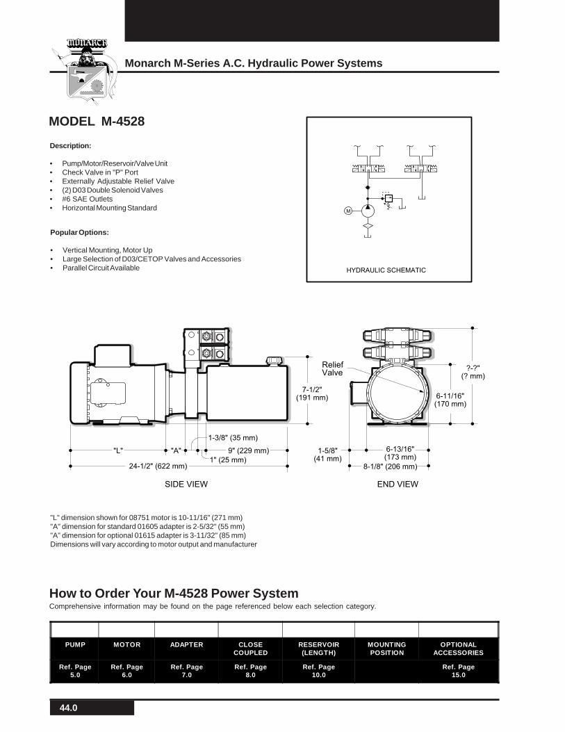
MODEL M-4528
"L" dimension shown for 08751 motor is 10-11/16" (271 mm)"A" dimension for standard 01605 adapter is 2-5/32" (55 mm)"A" dimension for optional 01615 adapter is 3-11/32" (85 mm)Dimensions will vary according to motor output and manufacturer
PUMP MOTOR ADAPTER CLOSECOUPLED
RESERVOIR(LENGTH)
MOUNTINGPOSITION
OPTIONALACCESSORIES
Ref. Page5.0
Ref. Page6.0
Ref. Page7.0
Ref. Page8.0
Ref. Page10.0
Ref. Page15.0
How to Order Your M-4528 Power SystemComprehensive information may be found on the page referenced below each selection category.
M
HYDRAULIC SCHEMATIC
ReliefValve
END VIEWSIDE VIEW
"L" "A"
?-?"(? mm)
7-1/2"(191 mm)
24-1/2" (622 mm)
1-5/8"(41 mm)
6-13/16"(173 mm)
8-1/8" (206 mm)1" (25 mm)
9" (229 mm)
1-3/8" (35 mm)
6-11/16"(170 mm)
Description:
• Pump/Motor/Reservoir/Valve Unit• Check Valve in "P" Port• Externally Adjustable Relief Valve• (2) D03 Double Solenoid Valves• #6 SAE Outlets• Horizontal Mounting Standard
Popular Options:
• Vertical Mounting, Motor Up• Large Selection of D03/CETOP Valves and Accessories• Parallel Circuit Available

45.0
Monarch Hydraulics, Inc.
MODEL M-466 Mini System
Description:
• Pump/Motor/Reservoir/Valve Unit• Cartridge Valve Block Manifolded Directly to Power Unit• Controls 2 Single Acting Cylinders Independently• .125 Inch NPT Outlets• Horizontal Mounting Standard• Vertical Mounting (Motor Up) Optional
NOTE: Consult factory regarding return flow limitations.
M
HYDRAULIC SCHEMATIC
OutletPorts
MountingHoles
END VIEWSIDE VIEW
5-13/16"(148 mm)
6-15/32"(164 mm)
14-17/32" (369 mm)
2-1/4"(57 mm)
6-1/2" (165 mm)
3-7/8"(98 mm)
FILL LINE
MONARCH
How to Order Your M-466 Mini SystemComprehensive information may be found on the page referenced below each selection category.
PUMP MOTOR CAPACITOR RESERVOIR MOUNTINGPOSITION
OPTIONALACCESSORIES
Ref. Page9.0
Ref. Page9.0
Ref. Page9.0
Ref. Page11.0
Ref. Page15.0
46.0
Monarch M-Series A.C. Hydraulic Power Systems
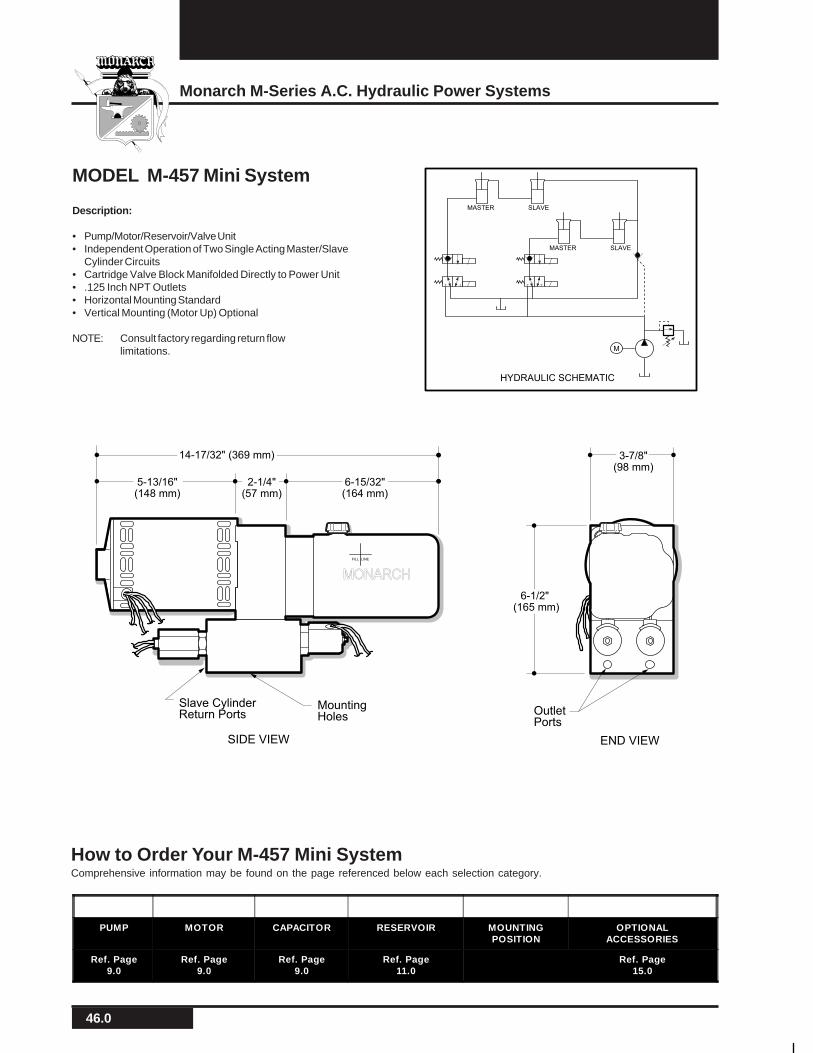
Description:
• Pump/Motor/Reservoir/Valve Unit• Independent Operation of Two Single Acting Master/Slave
Cylinder Circuits• Cartridge Valve Block Manifolded Directly to Power Unit• .125 Inch NPT Outlets• Horizontal Mounting Standard• Vertical Mounting (Motor Up) Optional
NOTE: Consult factory regarding return flowlimitations.
MODEL M-457 Mini System
M
MASTER SLAVE
MASTER SLAVE
HYDRAULIC SCHEMATIC
OutletPorts
MountingHoles
END VIEWSIDE VIEW
5-13/16"(148 mm)
6-15/32"(164 mm)
14-17/32" (369 mm)
2-1/4"(57 mm)
6-1/2" (165 mm)
3-7/8"(98 mm)
Slave CylinderReturn Ports
FILL LINE
MONARCH
How to Order Your M-457 Mini SystemComprehensive information may be found on the page referenced below each selection category.
PUMP MOTOR CAPACITOR RESERVOIR MOUNTINGPOSITION
OPTIONALACCESSORIES
Ref. Page9.0
Ref. Page9.0
Ref. Page9.0
Ref. Page11.0
Ref. Page15.0
47.0
Monarch Hydraulics, Inc.
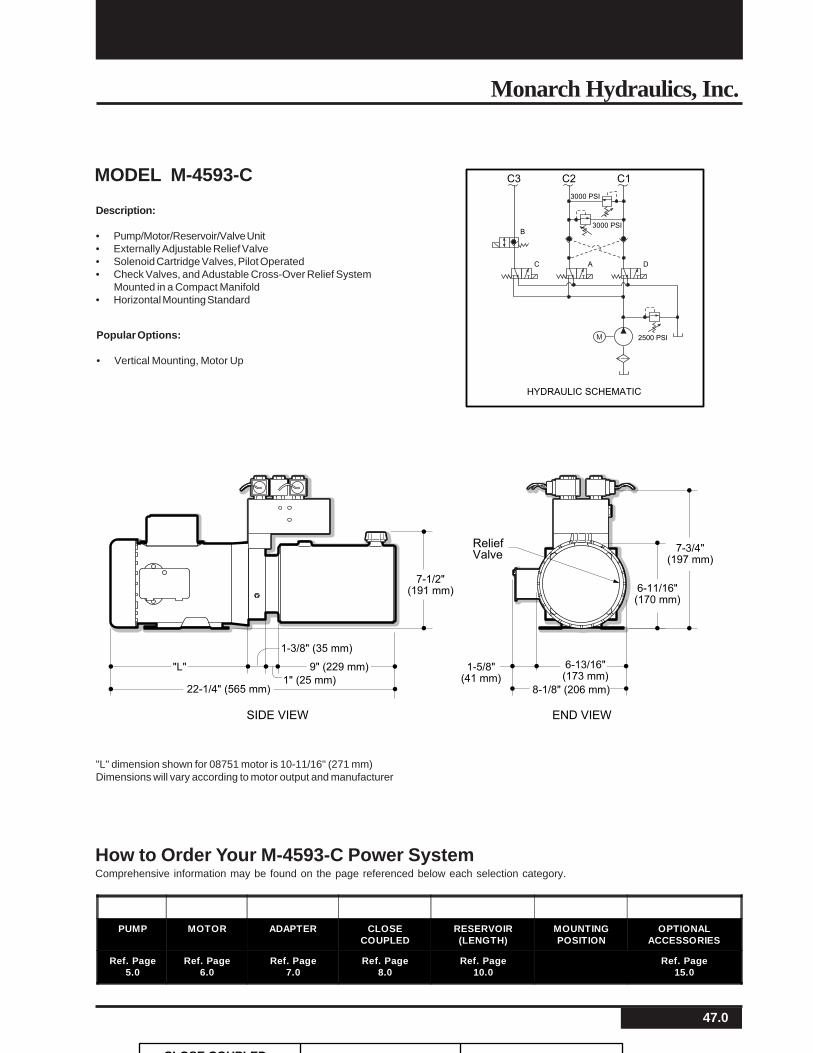
MODEL M-4593-C
"L" dimension shown for 08751 motor is 10-11/16" (271 mm)Dimensions will vary according to motor output and manufacturer
PUMP MOTOR ADAPTER CLOSECOUPLED
RESERVOIR(LENGTH)
MOUNTINGPOSITION
OPTIONALACCESSORIES
Ref. Page5.0
Ref. Page6.0
Ref. Page7.0
Ref. Page8.0
Ref. Page10.0
Ref. Page15.0
How to Order Your M-4593-C Power SystemComprehensive information may be found on the page referenced below each selection category.
HYDRAULIC SCHEMATIC
M
C1C2C3
2500 PSI
3000 PSI
3000 PSI
C A D
B
ReliefValve
END VIEWSIDE VIEW
"L"
7-3/4"(197 mm)
7-1/2"(191 mm)
22-1/4" (565 mm)
1-5/8"(41 mm)
6-13/16"(173 mm)
8-1/8" (206 mm)1" (25 mm)
9" (229 mm)
1-3/8" (35 mm)
6-11/16"(170 mm)
Description:
• Pump/Motor/Reservoir/Valve Unit• Externally Adjustable Relief Valve• Solenoid Cartridge Valves, Pilot Operated• Check Valves, and Adustable Cross-Over Relief System
Mounted in a Compact Manifold• Horizontal Mounting Standard
Popular Options:
• Vertical Mounting, Motor Up
CLOSE COUPLED
48.0
Monarch M-Series A.C. Hydraulic Power Systems
NOTES:

49.0
Monarch Hydraulics, Inc.
MT & T Series Industrial Power Units
50.0
Monarch M-Series A.C. Hydraulic Power Systems
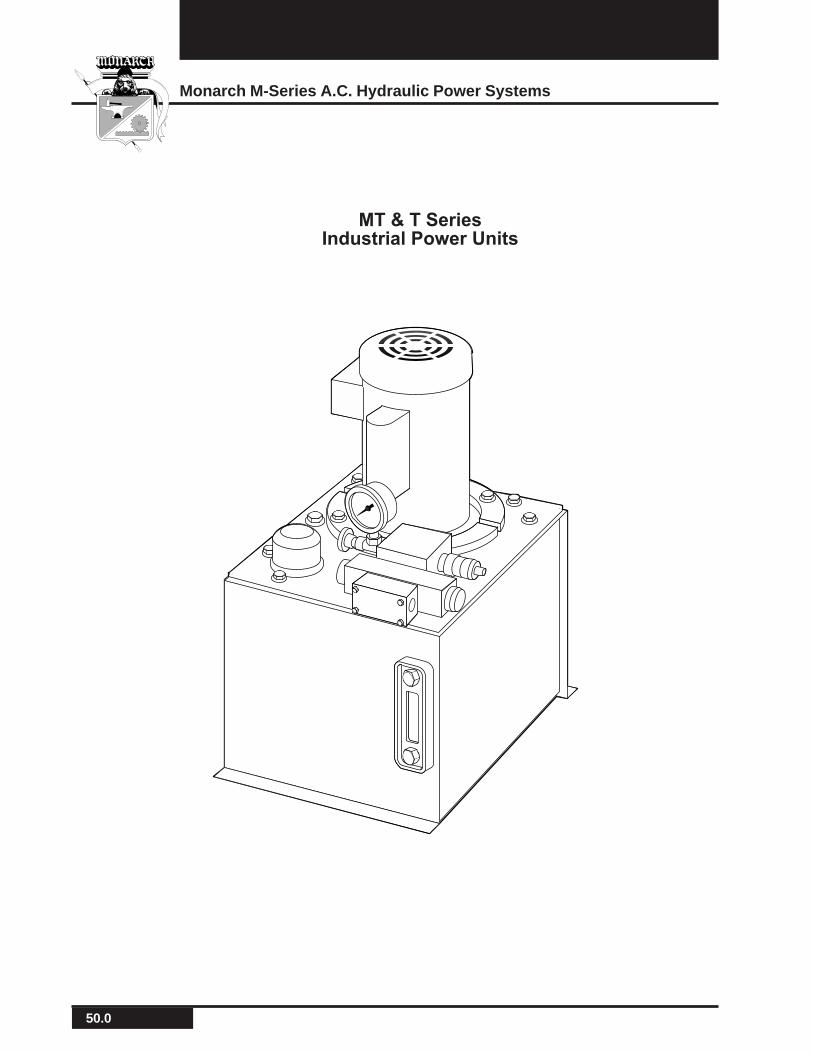
MT & T SeriesIndustrial Power Units
51.0
Monarch Hydraulics, Inc.
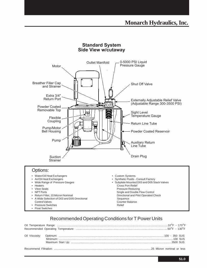
0-5000 PSI LiquidPressure Gauge
Shut Off Valve
Outlet Manifold
Standard SystemSide View w/cutaway
Motor
Breather Filler Capand Strainer
Extra 3/4"Return Port
Powder CoatedRemovable Top
FlexibleCoupling
Pump/MotorBell Housing
Pump
SuctionStrainer
Externally Adjustable Relief Valve(Adjustable Range 300-3500 PSI)
Sight LevelTemperature Gauge
Return Line Tube
Powder Coated Reservoir
Auxiliary ReturnLine Tube
Drain Plug
• Water/Oil Heat Exchangers• Air/Oil Heat Exchangers• Wide Range of Pressure Gauges• Heaters• Viton Seals• NPT Ports• Return Filter, 10 Micron Nominal• A Wide Selection of D03 and D05 Directional
Control Valves• Pressure Switches• Float Switches
• Custom Systems• Synthetic Fluids - Consult Factory• Subplate Mounted D03 and D05 Stack Valves
Cross Port Relief Pressure Reducing Single and Double Flow Control Directional and Pilot Operated Check Sequence Counter Balance Relief
Options:
Oil Temperature Range: ................................................................................................................................................10°F - 170°FRecommended Operating Temperature: .........................................................................................................................50°F - 130°F
Oil Viscosity: Optimum: ..........................................................................................................................................100 - 350 SUS Minimum: .........................................................................................................................................................100 SUS Maximum Start Up: .......................................................................................................................................3500 SUS
Recommend Filtration: ...............................................................................................................................25 Micron nominal or less
Recommended Operating Conditions for T Power Units
52.0
Monarch M-Series A.C. Hydraulic Power Systems
PUMP CODE IN3/REV RPM GPM500
HP
1000
HP
1500
HP
2000
HP
2500
HP
3000
HP
12637-150(72)
0.032 18003600
0.250.50
0.200.40
0.300.60
0.350.70
0.501.00
0.551.10
0.751.50
12637-270(62)
0.57 18003600
0.450.90
0.200.40
0.350.70
0.560.90
0.601.20
0.701.40
0.901.80
12172-150(42)
0.77 18003600
0.601.20
0.250.50
0.450.90
0.601.20
0.801.60
1.002.00
1.152.30
12172-200(43)
0.099 18003600
0.801.60
0.350.70
0.551.10
0.801.60
1.052.10
1.302.60
1.503.00
12172-250(03)
0.125 18003600
1.002.00
0.450.90
0.751.50
1.102.20
1.402.80
1.70 2.15
12172-270(51)
0.137 18003600
1.102.20
0.501.00
0.801.60
1.152.30
1.503.00
2.00 2.25
12172-380(05)
0.193 18003600
1.503.00
0.601.20
1.102.20
1.503.00
2.00 2.50 3.00
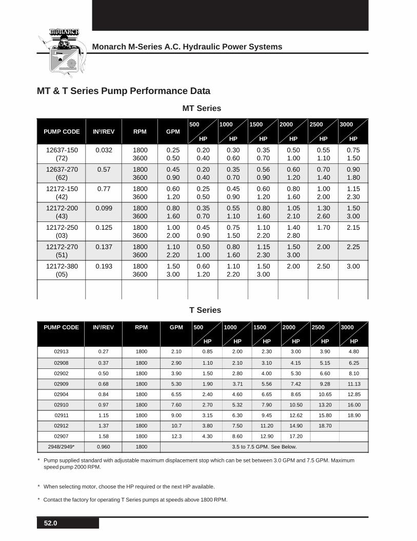
MT & T Series Pump Performance Data
MT Series
PUMP CODE IN3/REV RPM GPM 500
HP
1000
HP
1500
HP
2000
HP
2500
HP
3000
HP
02913 0.27 1800 2.10 0.85 2.00 2.30 3.00 3.90 4.80
02908 0.37 1800 2.90 1.10 2.10 3.10 4.15 5.15 6.25
02902 0.50 1800 3.90 1.50 2.80 4.00 5.30 6.60 8.10
02909 0.68 1800 5.30 1.90 3.71 5.56 7.42 9.28 11.13
02904 0.84 1800 6.55 2.40 4.60 6.65 8.65 10.65 12.85
02910 0.97 1800 7.60 2.70 5.32 7.90 10.50 13.20 16.00
02911 1.15 1800 9.00 3.15 6.30 9.45 12.62 15.80 18.90
02912 1.37 1800 10.7 3.80 7.50 11.20 14.90 18.70
02907 1.58 1800 12.3 4.30 8.60 12.90 17.20
2948/2949* 0.960 1800 3.5 to 7.5 GPM. See Below.
T Series
* Pump supplied standard with adjustable maximum displacement stop which can be set between 3.0 GPM and 7.5 GPM. Maximumspeed pump 2000 RPM.
* When selecting motor, choose the HP required or the next HP available.
* Contact the factory for operating T Series pumps at speeds above 1800 RPM.
53.0
Monarch Hydraulics, Inc.
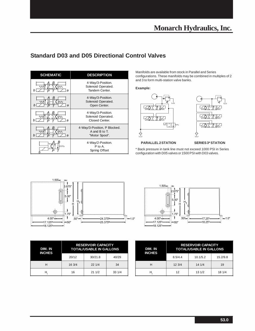
Standard D03 and D05 Directional Control Valves
Manifolds are available from stock in Parallel and Seriesconfigurations. These manifolds may be combined in multiples of 2and 3 to form multi-station valve banks.
Example:
PARALLEL 2 STATION SERIES 3* STATION
* Back pressure in tank line must not exceed 1000 PSI in Seriesconfiguration with D05 valves or 1500 PSI with D03 valves.
1.50"
2.875"
5.00"
HH1
17.125"
17.25" 1.0".50"
18.25"
18.125"
1.75"
4.00"
.50"
3.875"
25.375"
24.375" 1.0".50"
.50"
5.00"
17.125"
18.125"
4.00"
H
H1
1.75"
1.50"
DIM. ININCHES
RESERVOIR CAPACITYTOTAL/USABLE IN GALLONS
20/12 30/21.8 40/29
H 16 3/4 22 1/4 34
H1 16 21 1/2 33 1/4
DIM. ININCHES
RESERVOIR CAPACITYTOTAL/USABLE IN GALLONS
8.5/4.4 10.1/5.2 15.2/9.8
H 12 3/4 14 1/4 19
H1 12 13 1/2 18 1/4
SCHEMATIC DESCRIPTION
4-Way/3-Position.Solenoid Operated.
Tandem Center.
4-Way/3-Position.Solenoid Operated.
Open Center.
4-Way/3-Position.Solenoid Operated.
Closed Center.
4-Way/3-Position, P Blocked.A and B to T.
"Motor Spool".
4-Way/2-Position.P to A.
Spring Offset
A B
P T ab
A B
P T ab
A B
P T ab
A B
P Tb
A B
P T ab
54.0
Monarch M-Series A.C. Hydraulic Power Systems
_____ _____ _____ _____ _____ _____ _____ _____ _____ _____
SERIES PUMP RESERVOIR HEATEXCHANGER
MOTOR VALVE MANIFOLD
TOTAL CAPACITY(SEE SELECTION
CHART (ALL STANDARD MOTORS TEFC)GALLONS ON REVERSE PAGE)
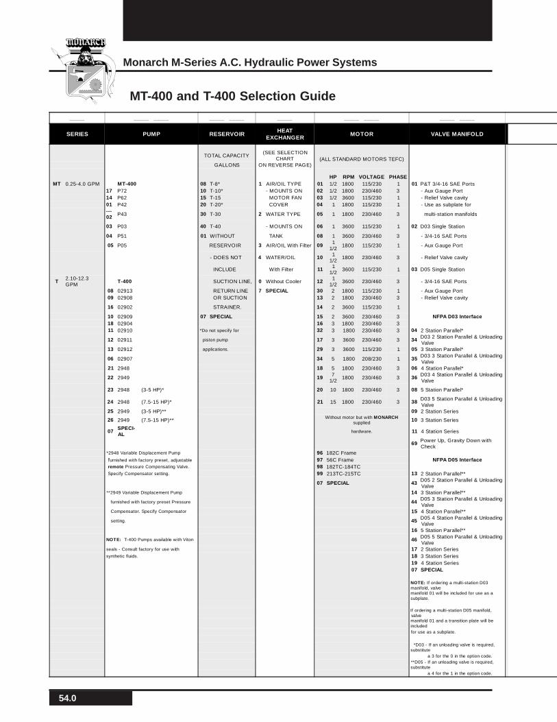
HP RPM VOLTAGE PHASEMT 0.25-4.0 GPM MT-400 08 T-8* 1 AIR/OIL TYPE 01 1/2 1800 115/230 1 01 P&T 3/4-16 SAE Ports
17 P72 10 T-10* - MOUNTS ON 02 1/2 1800 230/460 3 - Aux Gauge Port14 P62 15 T-15 MOTOR FAN 03 1/2 3600 115/230 1 - Relief Valve cavity01 P42 20 T-20* COVER 04 1 1800 115/230 1 - Use as subplate for---02 P43 30 T-30 2 WATER TYPE 05 1 1800 230/460 3 multi-station manifolds
03 P03 40 T-40 - MOUNTS ON 06 1 3600 115/230 1 02 D03 Single Station
04 P51 01 WITHOUT TANK 08 1 3600 230/460 3 - 3/4-16 SAE Ports
05 P05 RESERVOIR 3 AIR/OIL With Filter 09 11/2
1800 115/230 1 - Aux Gauge Port
- DOES NOT 4 WATER/OIL 10 11/2
1800 230/460 3 - Relief Valve cavity
INCLUDE With Filter 11 11/2
3600 115/230 1 03 D05 Single Station
T 2.10-12.3GPM
T-400 SUCTION LINE, 0 Without Cooler 12 11/2
3600 230/460 3 - 3/4-16 SAE Ports
08 02913 RETURN LINE 7 SPECIAL 30 2 1800 115/230 1 - Aux Gauge Port09 02908 OR SUCTION 13 2 1800 230/460 3 - Relief Valve cavity
16 02902 STRAINER. 14 2 3600 115/230 1
10 02909 07 SPECIAL 15 2 3600 230/460 3 NFPA D03 Interface18 02904 16 3 1800 230/460 311 02910 *Do not specify for 32 3 1800 230/460 3 04 2 Station Parallel*
12 02911 piston pump 17 3 3600 230/460 3 34 D03 2 Station Parallel & UnloadingValve
13 02912 applications. 29 3 3600 115/230 1 05 3 Station Parallel*
06 02907 34 5 1800 208/230 1 35 D03 3 Station Parallel & UnloadingValve
21 2948 18 5 1800 230/460 3 06 4 Station Parallel*
22 2949 19 71/2
1800 230/460 3 36 D03 4 Station Parallel & UnloadingValve
23 2948 (3-5 HP)* 20 10 1800 230/460 3 08 5 Station Parallel*
24 2948 (7.5-15 HP)* 21 15 1800 230/460 3 38 D03 5 Station Parallel & UnloadingValve
25 2949 (3-5 HP)** 09 2 Station Series
26 2949 (7.5-15 HP)**Without motor but with MONARCH
supplied10 3 Station Series
07SPECI-AL
hardware. 11 4 Station Series
69 Power Up, Gravity Down withCheck
*2948 Variable Displacement Pump 96 182C Frame furnished with factory preset, adjustable 97 56C Frame NFPA D05 Interface remote Pressure Compensating Valve. 98 182TC-184TC Specify Compensator setting. 99 213TC-215TC 13 2 Station Parallel**
07 SPECIAL 43 D05 2 Station Parallel & UnloadingValve
**2949 Variable Displacement Pump 14 3 Station Parallel**
furnished with factory preset Pressure 44 D05 3 Station Parallel & UnloadingValve
Compensator. Specify Compensator 15 4 Station Parallel**
setting. 45 D05 4 Station Parallel & UnloadingValve
16 5 Station Parallel**
NOTE: T-400 Pumps available with Viton 46 D05 5 Station Parallel & UnloadingValve
seals - Consult factory for use with 17 2 Station Seriessynthetic fluids. 18 3 Station Series
19 4 Station Series07 SPECIAL
NOTE: If ordering a multi-station D03manifold, valvemanifold 01 will be included for use as asubplate.
If ordering a multi-station D05 manifold,valvemanifold 01 and a transition plate will beincludedfor use as a subplate.
*D03 - If an unloading valve is required,substitute a 3 for the 0 in the option code.**D05 - If an unloading valve is required,substitute a 4 for the 1 in the option code.
MT-400 and T-400 Selection Guide
55.0
Monarch Hydraulics, Inc.
_____ _____ _____ _____ _____ _____ _____ _____ _____ _____ _____
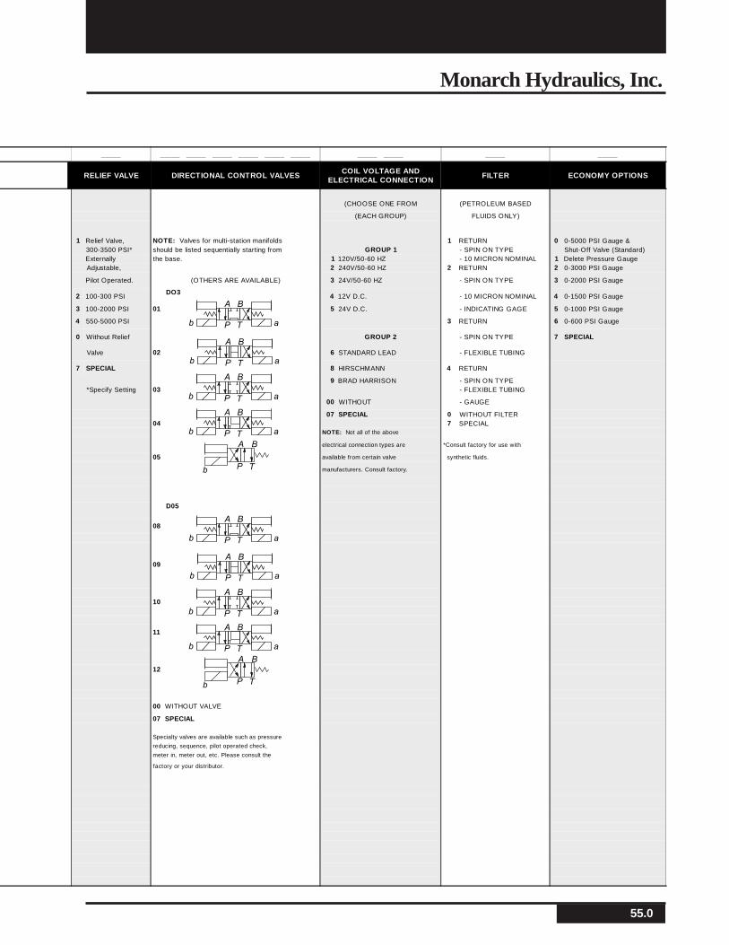
RELIEF VALVE DIRECTIONAL CONTROL VALVES COIL VOLTAGE ANDELECTRICAL CONNECTION
FILTER ECONOMY OPTIONS
(CHOOSE ONE FROM (PETROLEUM BASED
(EACH GROUP) FLUIDS ONLY)
1 Relief Valve, NOTE: Valves for multi-station manifolds 1 RETURN 0 0-5000 PSI Gauge &300-3500 PSI* should be listed sequentially starting from GROUP 1 - SPIN ON TYPE Shut-Off Valve (Standard)Externally the base. 1 120V/50-60 HZ - 10 MICRON NOMINAL 1 Delete Pressure GaugeAdjustable, 2 240V/50-60 HZ 2 RETURN 2 0-3000 PSI Gauge
Pilot Operated. (OTHERS ARE AVAILABLE) 3 24V/50-60 HZ - SPIN ON TYPE 3 0-2000 PSI Gauge
2 100-300 PSI DO3
4 12V D.C. - 10 MICRON NOMINAL 4 0-1500 PSI Gauge
3 100-2000 PSI 01 5 24V D.C. - INDICATING GAGE 5 0-1000 PSI Gauge
4 550-5000 PSI 3 RETURN 6 0-600 PSI Gauge
0 Without Relief GROUP 2 - SPIN ON TYPE 7 SPECIAL
Valve 02 6 STANDARD LEAD - FLEXIBLE TUBING
7 SPECIAL 8 HIRSCHMANN 4 RETURN
9 BRAD HARRISON - SPIN ON TYPE*Specify Setting 03 - FLEXIBLE TUBING
00 WITHOUT - GAUGE
07 SPECIAL 0 WITHOUT FILTER04 7 SPECIAL
NOTE: Not all of the above
gelectrical connection types are *Consult factory for use with
05 available from certain valve synthetic fluids.
gmanufacturers. Consult factory.
g
D05
g 08
09
10
g 11
g
12g
g 00 WITHOUT VALVE
07 SPECIAL
Specialty valves are available such as pressure
reducing, sequence, pilot operated check,
meter in, meter out, etc. Please consult the
factory or your distributor.
A B
P T ab
A B
P T ab
A B
P T ab
A B
P Tb
A B
P T ab
A B
P T ab
A B
P T ab
A B
P T ab
A B
P Tb
A B
P T ab
56.0
Monarch M-Series A.C. Hydraulic Power Systems
Limited 1 Year Warranty
Monarch Hydraulics, Inc. (“Monarch”) makes the following warranty to any party who purchases this Monarch productdirectly from Monarch with the intention of either reselling this Monarch product or incorporating it into or attaching itto some other product (“the purchaser”).
Monarch warrants to the purchaser that this product is free from any substantial defects in materials and workmanship.If this product proves to be defective in materials or workmanship during the period of this warranty, Monarch will repairor replace, at it’s option, the defective product free of charge (except for transportation charges as provided below). Theperiod of this warranty is the (1) year period beginning from the date of shipment of this Monarch product by Monarchto the purchaser.
To obtain warranty service, the purchaser must call Monarch to have a return goods authorization number assigned tothem. The purchaser should then send the product claimed to be defective within the warranty period, transportationprepaid, to: Monarch Hydraulics, Inc., 1363 Michigan Street N.E., Grand Rapids, MI. 49503. Monarch will then repairor replace, at it’s option, items which it finds to have been defective. Monarch will return such repaired or replacementitems to the sender free of charge. Items claimed by the purchaser, but not found by Monarch, to be defective will bereturned to the purchaser by a reasonably expeditious means at the purchaser’s expense. This expense may includelabor charges incurred from inspecting the unit.
This warranty does not extend to any failure of this Monarch product to perform as warranted hereinabove which iscaused by misuse, abuse or material alteration of this product, or any negligence in connection with the installation,service, or use of this product by any person other than Monarch.
Monarch hereby expressly disclaims any liability for consequential damages to property other than this Monarchproduct to perform as warranted hereinabove.
Note: Supersedes all former warranties written or implied.
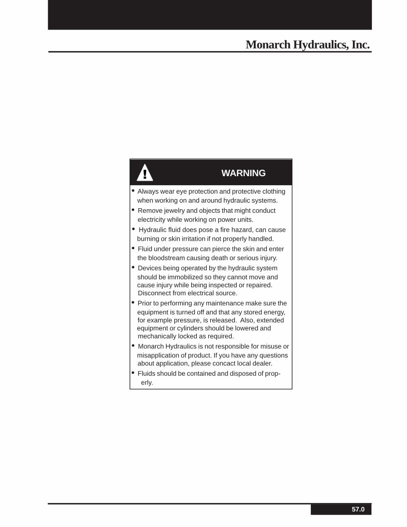
57.0
Monarch Hydraulics, Inc.
! WARNING
• Always wear eye protection and protective clothing when working on and around hydraulic systems.
• Remove jewelry and objects that might conduct electricity while working on power units.
• Hydraulic fluid does pose a fire hazard, can cause burning or skin irritation if not properly handled.
• Fluid under pressure can pierce the skin and enter the bloodstream causing death or serious injury.
• Devices being operated by the hydraulic system should be immobilized so they cannot move and cause injury while being inspected or repaired. Disconnect from electrical source.
• Prior to performing any maintenance make sure the equipment is turned off and that any stored energy, for example pressure, is released. Also, extended equipment or cylinders should be lowered and mechanically locked as required.
• Monarch Hydraulics is not responsible for misuse or misapplication of product. If you have any questions about application, please concact local dealer.
• Fluids should be contained and disposed of prop- erly.

58.0
Monarch M-Series A.C. Hydraulic Power Systems
NOTES:
59.0
Monarch Hydraulics, Inc.
NOTES:

60.0
Monarch M-Series A.C. Hydraulic Power Systems
NOTES:

61.0
Monarch Hydraulics, Inc.
Distributed By:
U.S.A.:
MONARCH HYDRAULICS, INC.
1363 Michigan St NE, Grand Rapids, MI 49503, U.S.A.
Telephone: (616) 458-1306
Telefax: (616) 458-1616
http://www.monarchhyd.com
Form No. 2256-06
CHINA:
ZHAOQING MONARCH HYDRAULICS CO. LTD.
5F, 434, Yeuxiu Road North
Guangzhou, 510050, PRC
Telephone: 0758-3642371
Telefax: 0758-3642373
www.monarch-hyd.cn
CANADA:
FLUID-PACK CORPORATION
A Part of the Monarch Hydraulics Group
460 Newbold St., London, Ontario, Canada N6E 1K3
Telephone: (519) 686-5900
Telefax: (519) 686-8976
www.fluidpack.com
Related Documents