This document contains a post-print version of the paper Model-based control concepts for vibratory MEMS gyroscopes authored by M. Egretzberger, F. Mair, A. Kugi and published in Mechatronics. The content of this post-print version is identical to the published paper but without the publisher’s final layout or copy editing. Please, scroll down for the article. Cite this article as: M. Egretzberger, F. Mair, A. Kugi, “Model-based control concepts for vibratory mems gyroscopes”, Mechatronics, 22, 3, 241–250, 2012. doi: 10.1016/j.mechatronics.2011.06.003 BibTex entry: @article{acinpaper, author = {Egretzberger, M. and Mair, F. and Kugi, A.}, title = {Model-based control concepts for vibratory MEMS gyroscopes}, journal = {Mechatronics}, year = {2012}, volume = {22}, number = {3}, pages = {241--250}, doi = {10.1016/j.mechatronics.2011.06.003}, url = {http://www.sciencedirect.com/science/article/pii/S0957415811001048} } Link to original paper: http://dx.doi.org/10.1016/j.mechatronics.2011.06.003 http://www.sciencedirect.com/science/article/pii/S0957415811001048 Read more ACIN papers or get this document: http://www.acin.tuwien.ac.at/literature Contact: Automation and Control Institute (ACIN) Internet: www.acin.tuwien.ac.at Vienna University of Technology E-mail: [email protected] Gusshausstrasse 27-29/E376 Phone: +43 1 58801 37601 1040 Vienna, Austria Fax: +43 1 58801 37699 Copyright notice: This is the authors’ version of a work that was accepted for publication in Mechatronics. Changes resulting from the publishing process, such as peer review, editing, corrections, structural formatting, and other quality control mechanisms may not be reflected in this document. Changes may have been made to this work since it was submitted for publication. A definitive version was subsequently published in M. Egretzberger, F. Mair, A. Kugi, “Model-based control concepts for vibratory mems gyroscopes”, Mechatronics, 22, 3, 241–250, 2012. doi: 10.1016/j.mechatronics.2011.06.003

Welcome message from author
This document is posted to help you gain knowledge. Please leave a comment to let me know what you think about it! Share it to your friends and learn new things together.
Transcript
This document contains a post-print version of the paper
Model-based control concepts for vibratory MEMS gyroscopes
authored by M. Egretzberger, F. Mair, A. Kugi
and published in Mechatronics.
The content of this post-print version is identical to the published paper but without the publisher’s final layout orcopy editing. Please, scroll down for the article.
Cite this article as:M. Egretzberger, F. Mair, A. Kugi, “Model-based control concepts for vibratory mems gyroscopes”, Mechatronics, 22,3, 241–250, 2012. doi: 10.1016/j.mechatronics.2011.06.003
BibTex entry:@article{acinpaper,author = {Egretzberger, M. and Mair, F. and Kugi, A.},title = {Model-based control concepts for vibratory MEMS gyroscopes},journal = {Mechatronics},year = {2012},volume = {22},number = {3},pages = {241--250},doi = {10.1016/j.mechatronics.2011.06.003},url = {http://www.sciencedirect.com/science/article/pii/S0957415811001048}
}
Link to original paper:http://dx.doi.org/10.1016/j.mechatronics.2011.06.003http://www.sciencedirect.com/science/article/pii/S0957415811001048
Read more ACIN papers or get this document:http://www.acin.tuwien.ac.at/literature
Contact:Automation and Control Institute (ACIN) Internet: www.acin.tuwien.ac.atVienna University of Technology E-mail: [email protected] 27-29/E376 Phone: +43 1 58801 376011040 Vienna, Austria Fax: +43 1 58801 37699
Copyright notice:This is the authors’ version of a work that was accepted for publication in Mechatronics. Changes resulting from the publishing process,such as peer review, editing, corrections, structural formatting, and other quality control mechanisms may not be reflected in this document.Changes may have been made to this work since it was submitted for publication. A definitive version was subsequently published in M.Egretzberger, F. Mair, A. Kugi, “Model-based control concepts for vibratory mems gyroscopes”, Mechatronics, 22, 3, 241–250, 2012. doi:10.1016/j.mechatronics.2011.06.003
Model-based Control Concepts for Vibratory MEMS
Gyroscopes
Markus Egretzberger, Florian Mair, Andreas Kugi
Vienna University of Technology, Automation and Control Institute,Gusshausstraße 27-29, 1040 Wien, Austria
Abstract
In this contribution, a systematic method for the design of open- and closed-loop controllers for vibratory MEMS gyroscopes based on so-called envelopemodels will be presented. The methodology will be exemplarily carried outfor a gyroscope with electrostatic actuation and read-out elements. Thespecifically designed capacitive actuators of the gyroscope are capable ofcompensating the system’s inherent mechanical unbalance (quadrature com-pensation) as well as the system’s response to an external angular rate (forcefeedback). The utilized envelope model solely captures the relevant systemdynamics of the gyroscope while at the same time describing the actuationand read-out mechanisms simplified to a suitable level of detail thus providingthe basis for an efficient and systematic control design.
In order to demonstrate the proposed methodology, an optimized start-upstrategy for the control of the primary oscillation is designed. Furthermore,the approach is utilized for the deviation of a basic quadrature controllerfor the secondary oscillation. In order to account for the typically weaklydamped open-loop dynamics of the gyroscope and the transient couplingbetween the quadrature and the angular rate signal a more sophisticatedcombined concept of closed-loop quadrature and force feedback control is in-troduced. Both simulation and measurement results obtained for a prototypegyroscope validate the mathematical models and prove the feasibility of theproposed concepts.
Keywords: MEMS gyroscopes, envelope model, capacitive sensors andactuators, quadrature error, force feedback.
Preprint submitted to Mechatronics May 17, 2011
Post-print version of the article: M. Egretzberger, F. Mair, A. Kugi, “Model-based control concepts for vibratory mems gyroscopes”,Mechatronics, 22, 3, 241–250, 2012. doi: 10.1016/j.mechatronics.2011.06.003The content of this post-print version is identical to the published paper but without the publisher’s final layout or copy editing.
1. Introduction
Vibratory micro electromechanical gyroscopes are typically driven by aprimary oscillator. This primary oscillation is usually excited close to theresonance frequency in order to achieve maximum amplitudes. Similar tomany electronic circuits, in particular in information technology, the wantedsignals are modulated in a high-frequency carrier signal. Hence, the rateof change of the wanted signals is several orders of magnitude slower thanthe carrier frequency itself. In the case of vibratory micro electromechanicalgyroscopes an external angular rate causes a secondary oscillation with anamplitude proportional to the angular rate component about the sensitiveaxis by exploiting the Coriolis effect. The output signal of the sensor (i.e., theangular rate) is obtained by an appropriate demodulation of the secondaryoscillation signal. In order to provide a linear sensor behavior and maximumsensitivity, the frequency and amplitude of the primary oscillation have to becontrolled. Furthermore, micro electromechanical gyroscopes are subject tolarge quadrature errors due to limitations in the fabrication process. Thesequadrature errors are due to a mechanical unbalance, which causes a cou-pling between the primary and secondary oscillation without the presenceof an external angular rate. This quadrature signal can be separated fromthe angular rate signal after the demodulation of the secondary oscillation.In order to avoid a drift of the output signal, e.g., over temperature, due todemodulation errors the mechanical unbalance has to be actively compen-sated. Therefore, an additional actuation of the secondary oscillator has tobe provided such that a controller can be implemented to suppress the un-wanted quadrature signal. Furthermore, in order to increase the bandwidthof the MEMS gyroscope so-called force feedback controllers are utilized toadditionally compensate the response to the external angular rate.
In this context, many articles dealing with the control of vibratory gy-roscopes can be found in the literature, see, e.g., [1, 2, 3, 4, 5]. All of thementioned control loops have in common that the relevant closed-loop dy-namics lie within the frequency range of the envelope of the signal ratherthan in the frequency range of the carrier signal itself. In particular from asystem analysis and control design point of view, this motivates to derive amore comprehensive mathematical model which solely captures the essential”slow” dynamics (envelope) of the system as proposed in [6].
In this contribution, the simplified envelope model introduced for vibra-tory gyroscopes in [6] will be used as the basis for the design of suitable
2
Post-print version of the article: M. Egretzberger, F. Mair, A. Kugi, “Model-based control concepts for vibratory mems gyroscopes”,Mechatronics, 22, 3, 241–250, 2012. doi: 10.1016/j.mechatronics.2011.06.003The content of this post-print version is identical to the published paper but without the publisher’s final layout or copy editing.
control concepts. The presented methodology will be exemplarily carriedout for a capacitive MEMS gyroscope. Thereby, the paper is organized asfollows: In Sec. 2, the working principle of vibratory gyroscopes is discussedin terms of the specific capacitive device under consideration. Furthermore,a suitable mathematical model in terms of a simplified envelope model ispresented in order to describe the essential dynamics of the primary andsecondary oscillation. Based on this simplified envelope model, Sec. 3 is de-voted to the derivation of suitable open- and closed-loop controllers for boththe primary and the secondary oscillation including an optimized start-upstrategy as well as the unbalance compensation and the force feedback of theangular rate response. Measurement results are presented in Sec. 4 and thepaper concludes with a short summary.
2. A capacitive gyroscope
The micro electromechanical device being considered in this paper is agyroscope consisting of a plane symmetric silicon structure operating with anin-plane primary mode, excited by capacitive comb actuators, and an out-of-plane secondary mode with capacitive parallel plate sensors. Most capacitivegyroscopes found in the literature are driven by electrostatic comb actuatorsbringing about the advantage of a high actuation stroke and little requiredspace. They are found in linear oscillating as well as in rotating designs,see, e.g., [7, 8, 9, 10]. For the same reason, the read-out of the secondaryoscillation is preferably also realized by means of comb sensors. Obviously,comb sensors require the secondary mode to be an in-plane oscillation as itis the case for the designs presented in [8, 9]. If the secondary mode is anout-of-plane oscillation, parallel plate capacitors are more suitable since themovable electrodes are designed to be part of the oscillating structure andthe corresponding fixed electrodes are directly mounted on the housing ofthe device, see, e.g., [11].
Within the scope of this work, let us restrict ourselves to one specificdesign of a capacitive gyroscope as presented in Fig. 1 which is an enhancedversion of the gyroscope presented in [11]. This design is capable of bothcompensating the mechanical unbalance and realizing a force feedback. Inthis section, the working principle of the capacitive gyroscope is explainedfirst and afterwards the appropriate mathematical model for the controllerdesign will be formulated.
3
Post-print version of the article: M. Egretzberger, F. Mair, A. Kugi, “Model-based control concepts for vibratory mems gyroscopes”,Mechatronics, 22, 3, 241–250, 2012. doi: 10.1016/j.mechatronics.2011.06.003The content of this post-print version is identical to the published paper but without the publisher’s final layout or copy editing.
fixed frame
movable frame
paddle
torsion beams
drive beams
(a) Primary mode
angular rate Ω
(b) Secondary mode
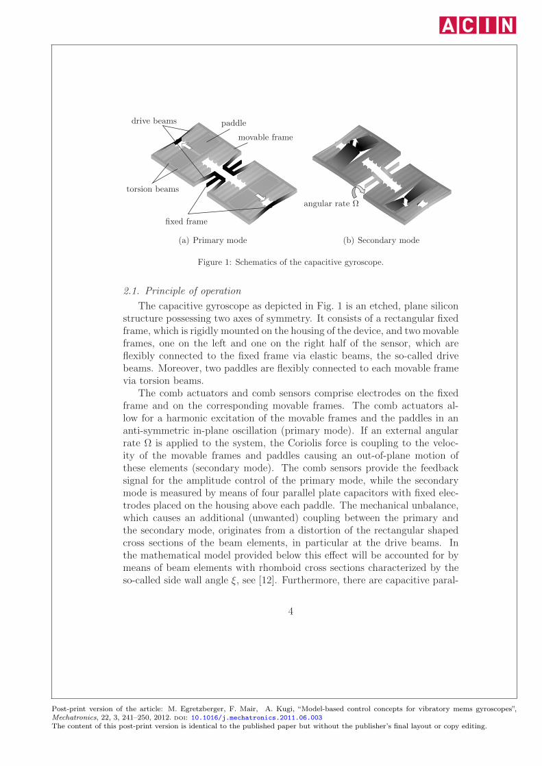
Figure 1: Schematics of the capacitive gyroscope.
2.1. Principle of operation
The capacitive gyroscope as depicted in Fig. 1 is an etched, plane siliconstructure possessing two axes of symmetry. It consists of a rectangular fixedframe, which is rigidly mounted on the housing of the device, and two movableframes, one on the left and one on the right half of the sensor, which areflexibly connected to the fixed frame via elastic beams, the so-called drivebeams. Moreover, two paddles are flexibly connected to each movable framevia torsion beams.
The comb actuators and comb sensors comprise electrodes on the fixedframe and on the corresponding movable frames. The comb actuators al-low for a harmonic excitation of the movable frames and the paddles in ananti-symmetric in-plane oscillation (primary mode). If an external angularrate Ω is applied to the system, the Coriolis force is coupling to the veloc-ity of the movable frames and paddles causing an out-of-plane motion ofthese elements (secondary mode). The comb sensors provide the feedbacksignal for the amplitude control of the primary mode, while the secondarymode is measured by means of four parallel plate capacitors with fixed elec-trodes placed on the housing above each paddle. The mechanical unbalance,which causes an additional (unwanted) coupling between the primary andthe secondary mode, originates from a distortion of the rectangular shapedcross sections of the beam elements, in particular at the drive beams. Inthe mathematical model provided below this effect will be accounted for bymeans of beam elements with rhomboid cross sections characterized by theso-called side wall angle ξ, see [12]. Furthermore, there are capacitive paral-
4
Post-print version of the article: M. Egretzberger, F. Mair, A. Kugi, “Model-based control concepts for vibratory mems gyroscopes”,Mechatronics, 22, 3, 241–250, 2012. doi: 10.1016/j.mechatronics.2011.06.003The content of this post-print version is identical to the published paper but without the publisher’s final layout or copy editing.
lel plate actuators provided for the excitation of the secondary mode, eachconsisting of several fixed electrodes placed above the movable frame and thepaddles. These additional actuators are intended for the active compensationof the mechanical unbalance as well as for the force feedback of the angularrate. All electrostatic actuators are assumed to be voltage controlled with adesired input voltage, see, e.g., [13]. The electrostatic sensors are realized bymeans of so-called charge amplifier circuits to convert the capacitance changeinto a proportional output voltage. These circuits are complemented by ap-propriate differential amplifiers in order to obtain suitable output signals forthe primary and secondary mode.
2.2. Dynamical model
As described in Sec. 2.1 the micro electromechanical device is composedof several components, i.e., the movable mechanical structure consisting ofrigid elements (movable frame, paddles), elastic elements (beam structures)and the electrostatic actuators (comb and parallel plate capacitors). In amore general form, the capacitive gyroscope can be considered as a multi-body system made up of rigid and elastic bodies with external forces appliedby the capacitive actuators. The equations of motion can be systematicallyderived by means of Lagrange’s formalism, e.g., by utilizing the approachpresented in [14]. The thus resulting model is in general a complex systemof non-linear ordinary differential equations as presented in [6]. However, ifonly the principal modes of operation are considered the resulting dynamicalsystem can be written in the simplified form, see [6],
[m1 00 m2
] [q1q2
]+
[d1 −c12Ωc12Ω d2
] [q1q2
]+
[k1 ξk12ξk12 k2
] [q1q2
]=
[f1f2
]
(1)with the primary mode q1 and the secondary mode q2 as well as the inertia,damping and stiffness coefficientsmj, dj and kj with j = 1, 2 and the couplingcoefficients due to the Coriolis force and the mechanical unbalance c12 andk12, respectively. The left-hand side of (1) is the typical representation of asimple autonomous mechanical model for vibratory MEMS gyroscopes, see,e.g., [15], while the electromechanical coupling forces f1 and f2 on the right-hand side strongly depend on the specific design of the electrostatic actuatorsas will be outlined in more detail below.
For the capacitive gyroscope under consideration, the comb capacitors ac-tuating the primary mode are specifically designed to generate an input force
5
Post-print version of the article: M. Egretzberger, F. Mair, A. Kugi, “Model-based control concepts for vibratory mems gyroscopes”,Mechatronics, 22, 3, 241–250, 2012. doi: 10.1016/j.mechatronics.2011.06.003The content of this post-print version is identical to the published paper but without the publisher’s final layout or copy editing.
f1 independent of the mechanical deflection (i.e. the primary and secondarymodes q1 and q2) of the form f1 = b1u
2P , see, e.g. [11], with the constant
parameter b1 and the primary input voltage uP such that the equation ofmotion for the primary mode can be written as
m1q1 + d1q1 + k1q1 − Ωc12q2 + ξk12q2 = b1u2P . (2)
The amplitudes of the primary mode q1 excited by the input voltage uP
are typically several orders of magnitude larger than the amplitudes of thesecondary mode excited by the weak coupling to the primary mode due tothe Coriolis force and the mechanical unbalance. Hence, for the purposeof system analysis and control design it is reasonable to assume that thecoupling terms from the secondary to the primary mode Ωc12q2 and ξk12q2in (2) are considerably small and thus can be neglected.
In contrast to the actuation of the primary mode, the parallel plate ac-tuators for the additional excitation of the secondary mode (intended forunbalance compensation and force feedback, see Sec. 2.1) are deliberatelydesigned to generate an input force f2 which specifically depends on themechanical deflections q1 and q2 yielding a nonlinear relation of the formf2 (q1, q2, uS,1, . . . , uS,m), with the secondary input voltages uS,i, i = 1, . . . ,m.The mathematical structure of the nonlinear term f2 strongly relies on theactual placement and orientation of the electrostatic actuators as will be seenbelow.
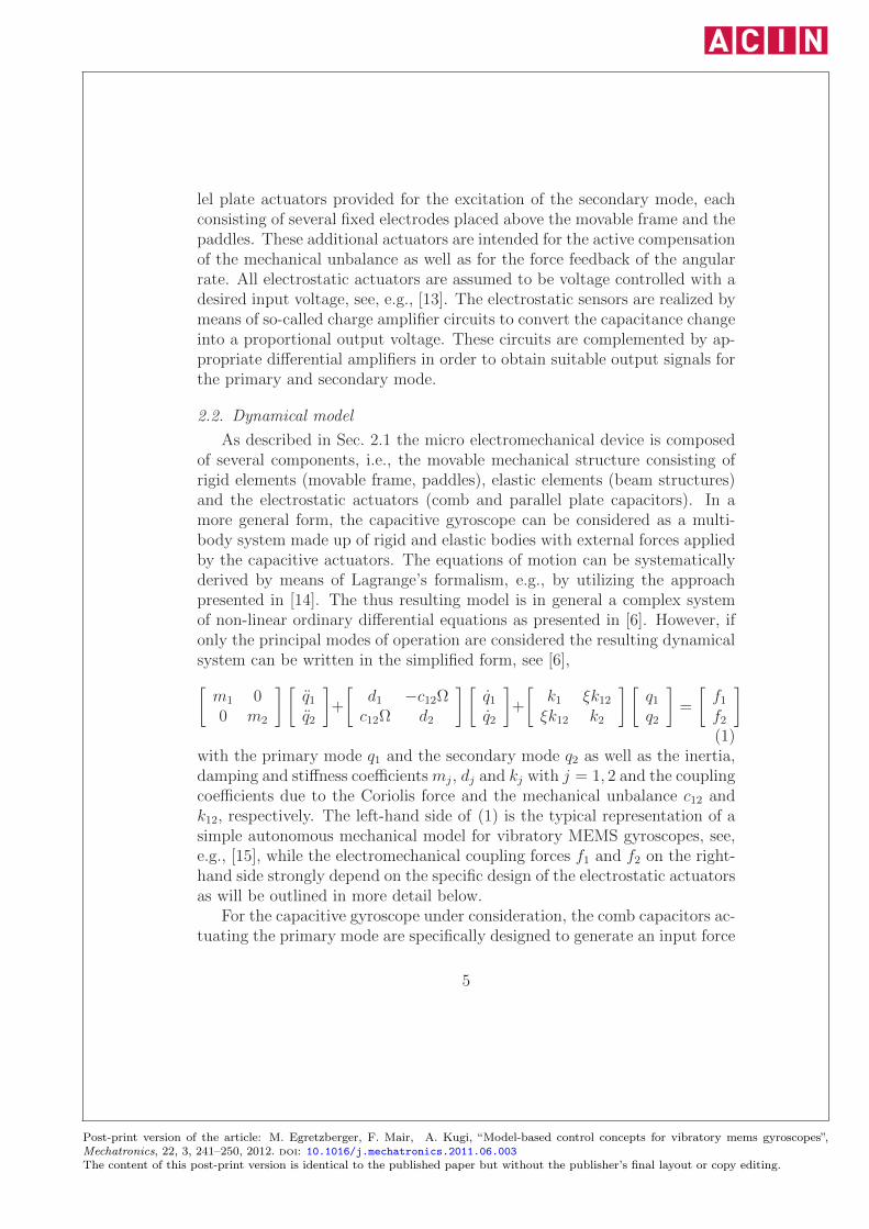
Considering these actuators as parallel plate capacitors with rectangularelectrodes, as shown in Fig. 2 for the i-th actuator, it is assumed that themovable electrode possesses two translational degrees-of-freedom, i.e. thedisplacements xi and zi of the center point aligned with the principal direc-tions of the primary and secondary motion, respectively. Thus, if no othermodes are excited the degrees-of-freedom can be written as xi = ±ri q1 andzi = ∓si q2 with the positive constants ri and si. The capacitance Ci and thepotential energy Wi of the i-th actuator is then given by
Ci = ε0Ai + xi tigi − zi
= ε0Ai ± ri ti q1gi ± si q2
, Wi =1
2Ci u
2S,i (3)
with the dielectric coefficient ε0, the gap gi, the width ti, the overlap areaAi = tili and the overlap length li in the undeformed configuration, see Fig. 2.The nonlinear input term f2 in (1) is calculated as
f2,i =∂Wi
∂q2= ∓1
2
ε0si (Ai ± ri ti q1)
(gi ± si q2)2 u2
S,i , f2 =m∑
i=1
f2,i . (4)
6
Post-print version of the article: M. Egretzberger, F. Mair, A. Kugi, “Model-based control concepts for vibratory mems gyroscopes”,Mechatronics, 22, 3, 241–250, 2012. doi: 10.1016/j.mechatronics.2011.06.003The content of this post-print version is identical to the published paper but without the publisher’s final layout or copy editing.
xizigi − zi
li + xi
housing
fixed electrode
movable electrode
Figure 2: Parallel plate capacitor.
From (3) and (4) it can be seen that, depending on the geometric design ofthe actuators, the secondary mode can be excited by a nonlinear term f2possessing four different algebraic sign permutations.
The specific gyroscope under consideration, see [11], however, is designedsuch that m = 4 capacitive parallel plate actuators generate an input termof the form
f2 =ε02
(s1 (A1 + r1 t1 q1)
(g1 − s1 q2)2 u2
S,1 −s2 (A2 + r2 t2 q1)
(g1 + s2 q2)2 u2
S,2
+s3 (A3 − r3 t3 q1)
(g1 − s3 q2)2 u2
S,3 −s4 (A4 − r4 t4 q1)
(g1 + s4 q2)2 u2
S,4
). (5)
Substituting the input transformation
uS,1 =√uT − uC + uS , uS,2 =
√uT + uC − uS ,
uS,3 =√uT + uC + uS , uS,4 =
√uT − uC − uS
(6)
into (5) and linearizing with respect to q1 and q2 about the point q1 = q2 = 0yields an approximation valid for small displacements. If all of the fouractuators possess the same gaps g = gi and the geometrical conditions sA =si Ai, r s t = ri si ti and s2A = s2iAi for i = 1, . . . , 4 hold (symmetry), thelinear approximation is given by
f2 �2ε0sA
g2︸ ︷︷ ︸b2
uS − 2ε0r s t
g2︸ ︷︷ ︸k12,C
q1 uC +4ε0 s
2A
g3︸ ︷︷ ︸k2,T
q2 uT . (7)
By making use of the approximation (7) the equation of motion of the sec-ondary mode according to (1) can be rewritten as
m2q2 + d2q2 + (k2 − k2,T uT ) q2 + Ωc12q1 + (k12 + k12,C uC) q1 = b2 uS , (8)
7
Post-print version of the article: M. Egretzberger, F. Mair, A. Kugi, “Model-based control concepts for vibratory mems gyroscopes”,Mechatronics, 22, 3, 241–250, 2012. doi: 10.1016/j.mechatronics.2011.06.003The content of this post-print version is identical to the published paper but without the publisher’s final layout or copy editing.
with the constant coefficients b2, k12,C and k2,T . It can be seen that thenew control inputs uS, uC and uT are decoupled with uS allowing for aharmonic excitation of the secondary mode, uC serves for the compensationof the unbalance and uT allows for the tuning of the stiffness and thus theresonance frequency of the secondary mode.
2.3. Envelope model
In the following, it is assumed that the primary mode is harmonicallyexcited by applying an input voltage of the form uP = UP,0+UP,C cos (ω t) tothe capacitive comb actuators with UP,0 ≥ UP,C . The excitation frequency ωis chosen to be close to the eigenfrequency of the primary mode ω1 in order toachieve maximum amplitudes. As is shown in detail in [6] it is reasonable tointroduce a so-called envelope model for the harmonically excited and weaklydamped resonance structure under consideration. Especially for the purposeof system analysis and control design this modeling technique has the advan-tage of reducing the overall dynamical system to a system with a manageablenumber of degrees-of-freedom solely describing the essential (slow) dynam-ics of the corresponding envelopes. Henceforth, the primary and secondarymode are approximated in the form qj = Qj,S sin (ω t)+Qj,C cos (ω t), j = 1, 2with the Fourier coefficients Qj,S and Qj,C , while the dc-components and thehigher harmonics are assumed to be negligible.
The envelope models of the primary and secondary mode correspondingto the dynamical systems (2) and (8) describing the dynamics of the Fouriercoefficients Qj,S and Qj,C can be derived according to [6] and are shortlyrecapitulated in the following two subsections.
2.3.1. Primary mode
Neglecting the weak coupling terms due to the angular rate Ω and theside wall angle ξ in (2) the envelope model of the primary mode describingthe dynamics of Q1,S and Q1,C is given by, see [6, 16],
d
dt
[Q1,S
Q1,C
]=
[−α1 ω − ω1
−ω + ω1 −α1
] [Q1,S
Q1,C
]−[β1
0
]UP,C (9)
and the output YP,β = c1 Q1,β, β ∈ {S,C} corresponds to the Fourier coeffi-cients of the primary output voltage yP = c1 q1 with the constant parameterc1. The component UP,C = 2UP,0 UP,C stems from the quadratic input non-linearity of the capacitive actuators. Furthermore, the damping coefficient
8
Post-print version of the article: M. Egretzberger, F. Mair, A. Kugi, “Model-based control concepts for vibratory mems gyroscopes”,Mechatronics, 22, 3, 241–250, 2012. doi: 10.1016/j.mechatronics.2011.06.003The content of this post-print version is identical to the published paper but without the publisher’s final layout or copy editing.
α1, the eigenfrequency ω1 and the input coefficient β1 of the primary modeare given by the relations, see [6, 16],
α1 =1
2
d1m1
, ω1 =1
2
1
m1
√4 k1m1 − d21 , β1 =
1
2
b1m1ω1
.
For the control design, it is beneficial to introduce an output transforma-tion to polar coordinates in the form
YP,A =√Y 2P,S + Y 2
P,C , YP,ϕ = arctan
(YP,S
YP,C
)(10)
with the amplitude YP,A and the phase YP,ϕ of the primary output voltage.In steady state, the amplitude and phase of the primary output voltage readas
YP,A =β1 c1 UP,C√
α21 + (ω − ω1)
2, YP,ϕ = arctan
(α1
ω1 − ω
).
Clearly, the maximum amplitude YP,A in steady state is obtained for theangular velocity ω = ω1 where at the same time the phase is YP,ϕ = −π/2.Hence, the first two tasks concerning the control of the primary mode canbe formulated as follows. The output phase YP,ϕ must be controlled to −π/2and the output amplitude YP,A to a predefined constant value YP,des.
2.3.2. Secondary mode
Now, let us assume that the primary mode is ideally controlled withYP,A = YP,des and YP,ϕ = −π/2 yielding the steady state Q1,S = YP,des/c1and Q1,C = 0. If the trimming and compensation inputs introduced in (6)are slowly varying signals uT = UT and uC = UC and the excitation input isa harmonic signal of the form uS = US,C cos (ω1t) the envelope model of thesecondary mode model (8) can be written as, see [6, 16],
d
dt
[Q2,S
Q2,C
]=
[−α2 ω1 − ω2
−ω1 + ω2 −α2
] [Q2,S
Q2,C
]+ β12
[Ω− ΓF US,C
ΓM + ΓC UC
],
(11)with the output YS,β = c2 Q2,β, β ∈ {S,C} denoting the Fourier coefficientsof the secondary output voltage yS = c2 q2, the damping coefficient α2 andthe eigenfrequency ω2 of the secondary mode
α2 =1
2
d2m2
, ω2 =1
2
1
m2
√4(k2 − k2,T UT
)m2 − d22 ,
9
Post-print version of the article: M. Egretzberger, F. Mair, A. Kugi, “Model-based control concepts for vibratory mems gyroscopes”,Mechatronics, 22, 3, 241–250, 2012. doi: 10.1016/j.mechatronics.2011.06.003The content of this post-print version is identical to the published paper but without the publisher’s final layout or copy editing.
respectively and the input coefficients
β12 =1
2
ω1
ω2
c12YP,des
c1m2
, ΓF =b2c1
ω1c12YP,des
,
ΓM =k12 ξ
ω1c12, ΓC =
k12,Cω1c12
.
In order to separate the response due to the external angular rate from theresponse due to the mechanical unbalance in the output Y = [YS,S, YS,C ]T,a transformation Z = TY of the form
T =
[sin (φ) cos (φ)cos (φ) − sin (φ)
], φ = arctan
(α2
ω2 − ω1
), (12)
with the new output Z = [ZS,R, ZS,Q ]T, is performed. Then, the steady stateof the system (11) with the output transformation (12) yields the Fouriercoefficients of the transformed output signals
ZS,R = S(Ω− ΓF US,C
), ZS,Q = −S
(ΓM + ΓC UC
)(13)
with the sensitivity
S =β12 c2√
α22 + (ω1 − ω2)
2.
In the output Z, the system (11) is stationarily decoupled and the compo-nents ZS,R and ZS,Q are denoted as the angular rate and the quadraturesignal, respectively. It can be seen from (13) that the mechanical unbalanceis compensated for ΓCUC = −ΓM , achieved by controlling the quadraturesignal ZS,Q to zero. The angular rate signal ZS,R either serves as the mea-surement output of the MEMS gyroscope or is compensated in the formΓF US,C = Ω in the case of force feedback control.
3. Control design
Within the scope of this paper the systematic design of open- and closed-loop controllers is exemplarily carried out for the control tasks formulatedin the previous section, i.e., the amplitude and phase control of the primarymode and the quadrature and force feedback control of the secondary mode.The theoretical concepts are verified by means of numerical simulations uti-lizing a simulation model with a high level of detail, see [6], and by means ofmeasurement results on a prototype gyroscope.
10
Post-print version of the article: M. Egretzberger, F. Mair, A. Kugi, “Model-based control concepts for vibratory mems gyroscopes”,Mechatronics, 22, 3, 241–250, 2012. doi: 10.1016/j.mechatronics.2011.06.003The content of this post-print version is identical to the published paper but without the publisher’s final layout or copy editing.
3.1. Control of the primary oscillation
A main objective of the primary control concept is the optimized start-up of the primary oscillation in the presence of parameter uncertainties. Inparticular the reference frequency provided by a quartz oscillator as well asthe eigenfrequencies of the gyroscopes are subject to fabrication tolerancesand to significant drifts due to the dependence of the material parameterson the temperature. A suitable solution for the start-up of the primaryoscillation is a sinusoidal sweep from a start frequency ω0 chosen to cover theworst case scenario for the smallest possible primary eigenfrequency and themaximum specified tolerance of the quartz oscillator. Then, the excitationis carried out in the form
UP,0 = UP,C =1
2UP,max , ω = ω0 + ζS t , t > 0 (14)
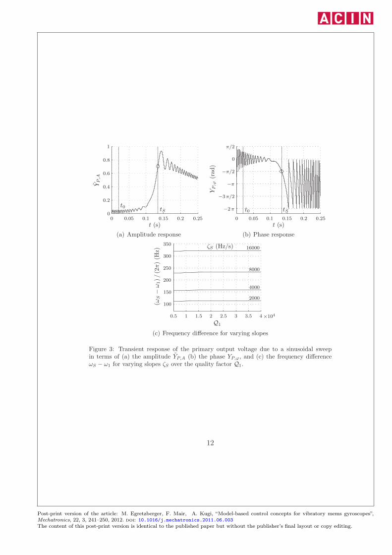
with the frequency slope ζS and the maximum possible primary excitationvoltage UP,max. The simulated transient response with ω0 = 0.98ω1 andζS = 2kHz/s in terms of the amplitude YP,A and the phase YP,ϕ is illustratedin Fig. 3(a) and respectively Fig. 3(b). There, the amplitude is normalizedwith respect to the desired amplitude YP,des in steady state in the form YP,A =YP,A/YP,des. The circles in Fig. 3 indicate the amplitude and phase of theprimary output voltage at the time t = tS when the phase is crossing the valueof −π/2 for the first time (apart from a short settling phase 0 ≤ t ≤ t0 that isneglected). The corresponding angular frequency at this time is ωS = ω (tS).If the sinusoidal sweep is performed for gyroscopes possessing different qualityfactors Q1 = ω1/(2α1), it turns out that the difference between ωS and theprimary eigenfrequency ω1 remains nearly constant, see Fig. 3(c). Since theidentified frequency difference ωS − ω1 is nearly independent of the qualityfactor Q1 for each slope ζS, the primary eigenfrequency can be estimated att = tS in the form
ω1 � ω1 = ωS −ΔωS, (15)
with ΔωS being the nominal frequency difference for each slope ζS. Thechoice of the maximum possible slope is limited by the minimum necessarysignal amplitude in order to achieve a proper signal-to-noise ratio.
The control design is now based on the system (9) starting from the initialcondition at t = tS with YP,A > 0 and YP,ϕ = −π/2. If the angular frequencyis chosen as ω = ω1 for t > tS the component Q1,C remains in the steadystate, i.e., the desired trajectory is Q∗
1,C = 0 with the output Y ∗P,ϕ = −π/2.
11
Post-print version of the article: M. Egretzberger, F. Mair, A. Kugi, “Model-based control concepts for vibratory mems gyroscopes”,Mechatronics, 22, 3, 241–250, 2012. doi: 10.1016/j.mechatronics.2011.06.003The content of this post-print version is identical to the published paper but without the publisher’s final layout or copy editing.
YP,A
t (s)
t0 tS00 0.05 0.1 0.15 0.25
1
0.8
0.6
0.4
0.2
0.2
(a) Amplitude response
YP,ϕ
(rad)
t (s)
t0 tS
0
0 0.05 0.1 0.15 0.2 0.25
π/2
−2π
−3π/2
−π
−π/2
(b) Phase response
(ωS−ω1)/(2π)(H
z)
Q1
100
150
200
250
300
350
0.5 1 1.5 2 2.5 3 3.5 4 ×10⁴
ζS (Hz/s)
2000
4000
8000
16000
(c) Frequency difference for varying slopes
Figure 3: Transient response of the primary output voltage due to a sinusoidal sweepin terms of (a) the amplitude YP,A (b) the phase YP,ϕ, and (c) the frequency differenceωS − ω1 for varying slopes ζS over the quality factor Q1.
12
Post-print version of the article: M. Egretzberger, F. Mair, A. Kugi, “Model-based control concepts for vibratory mems gyroscopes”,Mechatronics, 22, 3, 241–250, 2012. doi: 10.1016/j.mechatronics.2011.06.003The content of this post-print version is identical to the published paper but without the publisher’s final layout or copy editing.
Then, the (time optimal) control for the residual first order system, see (9),
d
dtQ∗
1,S = −α1 Q∗1,S − β1 U
∗P,C
is given by the maximum possible constant input U∗P,C until the trajectory
Y ∗P,A = c1 Q
∗1,S has reached the desired amplitude YP,des at the time t = tA.
For t ≥ tA, we aim at staying in the steady state Y ∗P,A = YP,des. This is
achieved for the feedforward control input
ω∗ = ω1, tS ≤ t and U∗P,C =
⎧⎪⎪⎨⎪⎪⎩
1
2U2P,max tS ≤ t < tA
− α1
β1 c1YP,des t ≥ tA .
(16)
In reality, however, the real model parameters α1, ω1, β1 and c1 differ fromthe nominal values α1, ω1, β1 and c1. Thus, it is reasonable to substitute theestimation ω1 for the primary eigenfrequency ω1, cf. (15), in the feedforwardcontrol (16), i.e., ω∗ = ωS−ΔωS, while the input U
∗P,C can only be calculated
for the nominal parameter values α1, β1 and c1. Therefore, a drift of the phaseYP,ϕ and the amplitude YP,A is inevitable, which necessitates the design of asuitable closed-loop control.
After the sinusoidal sweep for the time 0 ≤ t < tS, the second stage ofthe primary control is the phase control, where the excitation frequency iscomposed of the feedforward and feedback control inputs ω∗ and Δω in theform
ω = ω∗ +Δω for t ≥ tS . (17)
During this control stage the maximum possible primary input voltage U∗P,C =
U2P,max/2 is applied until the desired amplitude YP,des is reached at t = tA.
Then, in the third stage, i.e. for t ≥ tA, a combined phase and amplitudecontrol is performed. For the feedback control of the amplitude, a new in-put ΔUP,C is introduced yielding the coefficients of the primary excitationvoltage in the form
UP,C =
⎧⎪⎪⎨⎪⎪⎩
1
2UP,max
UP,ctrl
UP,0 =
⎧⎪⎪⎨⎪⎪⎩
1
2UP,max tS ≤ t < tA
1
2
U∗P,C +ΔUP,C
UP,ctrl
t ≥ tA ,(18)
13
Post-print version of the article: M. Egretzberger, F. Mair, A. Kugi, “Model-based control concepts for vibratory mems gyroscopes”,Mechatronics, 22, 3, 241–250, 2012. doi: 10.1016/j.mechatronics.2011.06.003The content of this post-print version is identical to the published paper but without the publisher’s final layout or copy editing.
with a suitable constant parameter UP,ctrl.For the design of the feedback controller, the system (9) with output (10)
is linearized around the desired operating point Q∗1,S = YP,des/c1, Q
∗1,C = 0,
ω∗ = ω1 and U∗P,C = −α1 YP,des/ (β1 c1) yielding a linear time-invariant system
of the form
d
dt
[ΔQ1,S
ΔQ1,C
]= −
[α1 00 α1
][ΔQ1,S
ΔQ1,C
]−[
0 β1
Q∗1,S 0
][Δω
ΔUP,C
](19a)
with the output
[ΔYP,A
ΔYP,ϕ
]=
[c1 00 −1/Q∗
1,S
] [ΔQ1,S
ΔQ1,C
](19b)
and the deviations ΔQ1,S, ΔQ1,C , ΔYP,A and ΔYP,ϕ from the operating point.It can be seen that the linearized system (19) is decoupled from the controlinput Δω and ΔUP,C to the output ΔYP,ϕ and ΔYP,A with the correspondingtransfer functions
GP,ϕ (s) =1
s+ α1
, GP,A (s) = − β1 c1s+ α1
, (20)
and the Laplace variable s. Based on (20) two PI-controllers are designed bymeans of the loop-shaping method in such a way that the rise times of theclosed-loop step responses become considerably small without entailing anovershooting. This linearized approach is reasonable as long as the deviationsare sufficiently small. It has proven robust against parameter variations anddifferent frequency slopes of the sinusoidal sweep, see also the measurementresults in Sec. 4.
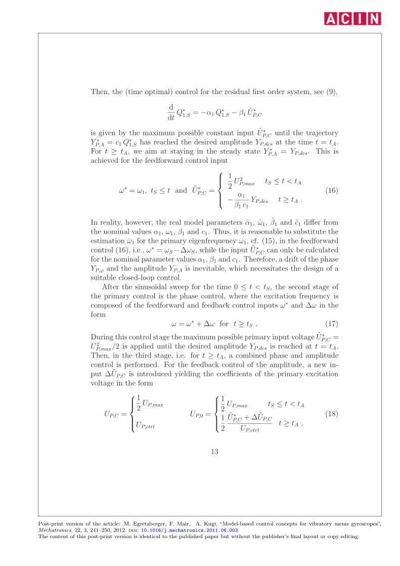
Summarizing, the start-up control strategy for the primary oscillationcan be separated into three phases, namely the sinusoidal sweep (stage I,0 ≤ t ≤ tS), the open-loop amplitude and closed-loop phase control (stageII, tS < t ≤ tA) and the closed-loop amplitude and phase control (stageIII, t > tA). The corresponding simulation results in terms of the outputsignals YP,A and YP,ϕ and the corresponding control inputs UP,0, UP,C and ωare depicted in Fig. 4. The frequency slope of the sinusoidal sweep is chosenas ζS = 8kHz/s. The performance of the amplitude and phase controller isillustrated for a gyroscope with (A) an increased damping parameter α1 =1.33α1, (B) the nominal damping parameter α1 = α1 and (C) a decreaseddamping parameter α1 = 0.5α1.
14
Post-print version of the article: M. Egretzberger, F. Mair, A. Kugi, “Model-based control concepts for vibratory mems gyroscopes”,Mechatronics, 22, 3, 241–250, 2012. doi: 10.1016/j.mechatronics.2011.06.003The content of this post-print version is identical to the published paper but without the publisher’s final layout or copy editing.
t
tS tA
YP,A
(A) (B) (C)
00 0.05 0.1 0.15 0.2 0.25 0.3
1
0.8
0.6
0.4
0.2I II III
(a) Amplitude
t
tS tA
UP,γ/U
P,m
ax
(A)
(B)
(C)
UP,0
UP,C
00 0.05 0.1 0.15 0.2 0.25 0.3
0.1
0.2
0.3
0.4
0.5
I II III
(b) Excitation voltages
t
tS tA
YP,ϕ
(rad)
ω/ω
1
YP,ϕ
ω/ω1
0
0 0.05 0.1 0.15 0.2 0.25 0.3
π/4
−π/4
−π/20.998
0.999
1.000
1.001
I II III
(c) Phase and excitation frequency
Figure 4: Start-up phase of the primary control in terms of (a) the normalized amplitudeYP,A, (b) the primary excitation voltages UP,γ , γ ∈ {0, C} and (c) the phase YP,ϕ of theprimary output voltage and the excitation frequency ω.
The time axis with t = t/tN in Fig. 4 is normalized to the time tN , whichis a predefined value marking the end of the start-up phase. For t ≥ tN thegyroscope is considered to operate in the normal mode providing a reliablemeasurement output with a predefined accuracy for the externally appliedangular rate Ω.
3.2. Control of the secondary oscillation
Typically, two modes of operation can be distinguished for vibratoryMEMS gyroscopes, namely the split mode, if there is a predefined nomi-nal difference between the primary and secondary eigenfrequency, and thematched mode, if the secondary eigenfrequency is controlled to match theprimary eigenfrequency, see, e.g., [15]. Within this subsection, the focus is
15
Post-print version of the article: M. Egretzberger, F. Mair, A. Kugi, “Model-based control concepts for vibratory mems gyroscopes”,Mechatronics, 22, 3, 241–250, 2012. doi: 10.1016/j.mechatronics.2011.06.003The content of this post-print version is identical to the published paper but without the publisher’s final layout or copy editing.
laid on the derivation of a quadrature controller and a combined quadratureand force feedback controller for a sensor designed to operate in the splitmode with a constant input UT and thus a constant frequency difference|ω1 − ω2| > 0, respectively.
3.2.1. Quadrature control
Starting point for the following considerations is the envelope model ofthe secondary mode (11). The corresponding transfer function matrix fromthe input U = [ US,C , UC ]T to the output Y = [YS,S, YS,C ]T is given by
G (s)=−β12c2
(s+α2)2+(ω1−ω2)
2
[ −(s+ α2) ΓF (ω1−ω2) ΓC
(ω1−ω2) ΓF (s+α2) ΓC
](21)
Considering the stationary decoupling by means of the transformation (12),the behavior of the MIMO system from the input U to the transformedoutput Z = [ZS,R, ZS,Q ]T is described by the transfer function matrix
H (s) = TG (s) =
[H11 (s) H12 (s)H21 (s) H22 (s)
](22)
with lims→0 H12 (s) = lims→0 H21 (s) = 0.In its simplest form, the control of the secondary mode merely covers
the closed-loop control for the unbalance compensation, while the angularrate signal is obtained from the open-loop measurement output ZS,R of thegyroscope according to (13). Thus, the quadrature controller can be eas-ily derived for the linear and time-invariant SISO system described by thetransfer function H22 (s). The demands on the closed-loop behavior are apredefined rise time and the exact suppression of a constant mechanical un-balance in the stationary case. The quadrature controller is activated at thetime t = tA when it can be assumed that the phase controller is in steadystate and thus the demodulation yields proper output signals ZS,R and ZS,Q.
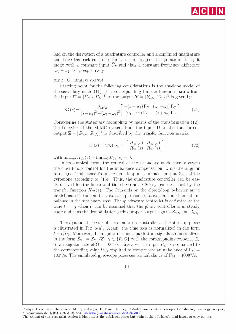
The dynamic behavior of the quadrature controller at the start-up phaseis illustrated in Fig. 5(a). Again, the time axis is normalized in the formt = t/tN . Moreover, the angular rate and quadrature signals are normalizedin the form ZS,γ = ZS,γ/Zr, γ ∈ {R,Q} with the corresponding response Zr
to an angular rate of Ω = 100◦/s. Likewise, the input UC is normalized tothe corresponding value UC,r required to compensate an unbalance of ΓM =100◦/s. The simulated gyroscope possesses an unbalance of ΓM = 1000◦/s.
16
Post-print version of the article: M. Egretzberger, F. Mair, A. Kugi, “Model-based control concepts for vibratory mems gyroscopes”,Mechatronics, 22, 3, 241–250, 2012. doi: 10.1016/j.mechatronics.2011.06.003The content of this post-print version is identical to the published paper but without the publisher’s final layout or copy editing.
t
tA
ZS,R,ZS,Q
ZS,R
ZS,Q
UC/U
C,r
UC
00
0 0.25 0.5 0.75 1
2
-2
-4
-6
5
-5
-15
-10
(a) Start-up phase
t− tN (s)t− tN (s)
ZS,R
ZS,Q
(i) stat.(i) stat.
(ii) dyn.(ii) dyn.
00
00 0.050.05 0.10.1 0.150.15-1-1
11
22
(b) Normal mode of operation
Figure 5: Dynamic behavior of the quadrature controller (a) in the start-up phase and (b)in the normal mode of operation in response to a step input of the external angular rateΩ in the case of (i) stationary and (ii) dynamic decoupling.
The dynamic response of the closed-loop system to an input step of theangular rate Ω in terms of the normalized quantities ZS,R and ZS,Q is il-lustrated in Fig. 5(b). It can be clearly seen that, although the angularrate signal ZS,R and the quadrature signal ZS,Q are stationarily decoupled,they show a strong coupling in the transient phase. Furthermore, due to theconsidered open-loop measurement of the angular rate the weakly dampedsystem dynamics cannot be influenced in the output signal ZS,R. In order toeliminate these unwanted system characteristics, in the next step a closed-loop force feedback controller comprising a dynamic decoupling of the outputsignals will be derived.
17
Post-print version of the article: M. Egretzberger, F. Mair, A. Kugi, “Model-based control concepts for vibratory mems gyroscopes”,Mechatronics, 22, 3, 241–250, 2012. doi: 10.1016/j.mechatronics.2011.06.003The content of this post-print version is identical to the published paper but without the publisher’s final layout or copy editing.
3.2.2. Combined quadrature and force feedback control
If the output transformation is performed by means of the transfer func-tion matrix
T (s) = Sα2
β12c2
⎡⎢⎣
−1ω1 − ω2
s+ α2ω1 − ω2
s+ α2
1
⎤⎥⎦ (23)
the MIMO system (11) can be dynamically decoupled such that the transferbehavior of the MIMO system (11) from the input U to the transformedoutput Z is given by the transfer function matrix
K (s) = T (s) G (s) =
[K1 (s) 0
0 K2 (s)
](24)
with the diagonal components
K1 (s) = −Sα2 ΓF
s+ α2
and K2 (s) = −Sα2 ΓC
s+ α2
.
The constant factor S α2/(β12c2) in (23) is introduced in order to achieve thestationary solution lims→0 K1(2) (s) = −S ΓF (C).
Now, the design of the quadrature controller from Sec. 3.2.1 can be per-formed on the basis of the linear time-invariant SISO system K2(s) insteadof H22(s) which is dynamically decoupled from the system K1(s). The corre-sponding simulation results in the normal mode of operation can be found inFig. 5(b). Additionally, a force feedback controller can be designed indepen-dently for the system K1(s) with the following demands on the closed-loopbehavior. The system should exhibit a predefined rise time and the outputsignal ZS,R has to be stationarily controlled to zero for a constant externalangular rate Ω. The closed-loop control is again activated at the time t = tAbut in this concept, however, the actual measurement output (the angularrate signal) is taken directly from the force feedback control input US,C .
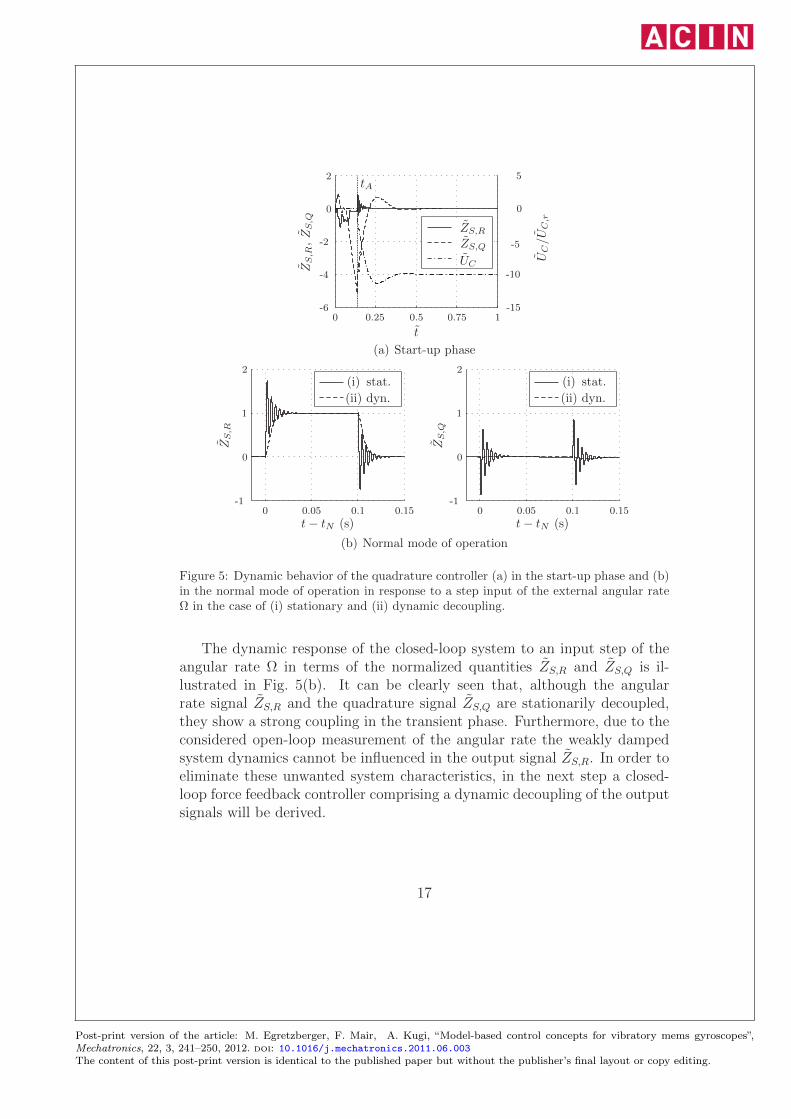
Figure 6(a) illustrates the dynamic behavior of the combined quadratureand force feedback controller in the start-up phase. In the normal mode ofoperation, the closed-loop system responds to an input step of the externalangular rate Ω as depicted in Fig. 6(b), where an almost perfect decouplingbetween the angular rate signal ZS,R and the quadrature signal ZS,Q can beobserved during the dynamic response. The corresponding force feedbackinput US,C as illustrated in Fig. 6(b) directly serves as the measurementoutput of the gyroscope.
18
Post-print version of the article: M. Egretzberger, F. Mair, A. Kugi, “Model-based control concepts for vibratory mems gyroscopes”,Mechatronics, 22, 3, 241–250, 2012. doi: 10.1016/j.mechatronics.2011.06.003The content of this post-print version is identical to the published paper but without the publisher’s final layout or copy editing.
t
tA
ZS,R,ZS,Q
ZS,R
ZS,Q
UC/U
C,r
UC
0
0
0
0.25 0.5 0.75 1
2
-2
-4
-6
5
-5
-15
-10
(a) Start-up phase
t− tN (s)t− tN (s)
ZS,R,ZS,Q
ZS,R
ZS,Q
US,C/U
C,r
US,C
Ω(◦/s)
Ω 00
0
00 0.050.05 0.10.1 0.150.15
-0.2
-0.4
0.4
0.2
0.02
0.04
0.06
50
100
(b) Normal mode of operation
Figure 6: Dynamic behavior of the combined quadrature and force feedback controller (a)in the start-up phase and (b) in the normal mode of operation in response to a step inputof the external angular rate Ω.
In contrast to the basic control concept the combined, dynamically decou-pled concept of quadrature and force feedback control allows for actively tun-ing the closed-loop dynamics of the gyroscope. This advantage can be directlyseen by comparing the response of the measurement output in Fig. 5(b), i.e.the angular rate signal, whose dynamic behavior is inherently given by theopen-loop dynamics of the system (the natural damping and eigenfrequencyof the secondary mode), with the response of the measurement output inFig. 6(b), i.e. the force feedback input signal, which is tuned by the appro-priate control design. The combined control concept including force feedbacktherefore is essential in particular if the natural damping of the secondarymode is small and the necessary bandwidth of the measurement output can-not be achieved in open-loop. However, the drawback of this method, besides
19
Post-print version of the article: M. Egretzberger, F. Mair, A. Kugi, “Model-based control concepts for vibratory mems gyroscopes”,Mechatronics, 22, 3, 241–250, 2012. doi: 10.1016/j.mechatronics.2011.06.003The content of this post-print version is identical to the published paper but without the publisher’s final layout or copy editing.
the slightly increasing electronic circuit complexity, is that since the neces-sary force feedback input US,C is small compared to the compensation inputUC (a factor of approximately 15 for the gyroscope under consideration) thedemands on the resolution of the corresponding DACs are increasing.
In reality, the model parameters α2, ω2, β12 and c2 differ from the nom-inal values α2, ω2, β12 and c2 thus necessitating an appropriate calibrationprocedure. For the basic control concept discussed in Subsec. 3.2.1 this cansimply be realized by adjusting the demodulation of the secondary mode sig-nal, i.e. the output transformation (12), which directly yields the parameterφ. For the combined control concept the frequency difference ω1 − ω2 can beobtained in a similar manner by adjusting the demodulation of the secondarymode signal, i.e. the output transformation (23) in steady state, cf. K1(s)and K2(s) in (24) for s → 0. Then, a stationary decoupling of the measure-ment output is achieved. In order to improve the closed-loop performanceand to realize a dynamical decoupling as proposed in Subsec. 3.2.2 also thedamping parameter α2 has to be identified by means of standard proceduresfor second order linear systems.
4. Experimental validation
To verify the control concepts introduced in Sec. 3 the correspondingcontrollers were implemented on a development board consisting of a FieldProgrammable Gate Array (FPGA) and additional analog circuitry for theactuation and read-out of a prototype capacitive gyroscope with an unbalanceof ΓM = 830◦/s. Special emphasis was placed on solely utilizing such logicresources of the FPGA which are available in standard ASIC processes. Thisis of particular importance especially in view of the targeted mass productionof the considered MEMS gyroscopes.
The zero crossing of the primary mode signal is detected by a discreteexternal comparator which together with a digital phase frequency detectorprovides the signal ΔYP,ϕ. The primary and secondary mode signals are con-verted from the analog to the digital domain and the signal ΔYP,A is derivedby calculating the magnitude of the primary mode signal, while ZS,R andZS,Q are obtained by an appropriate demodulation of the secondary modesignal.
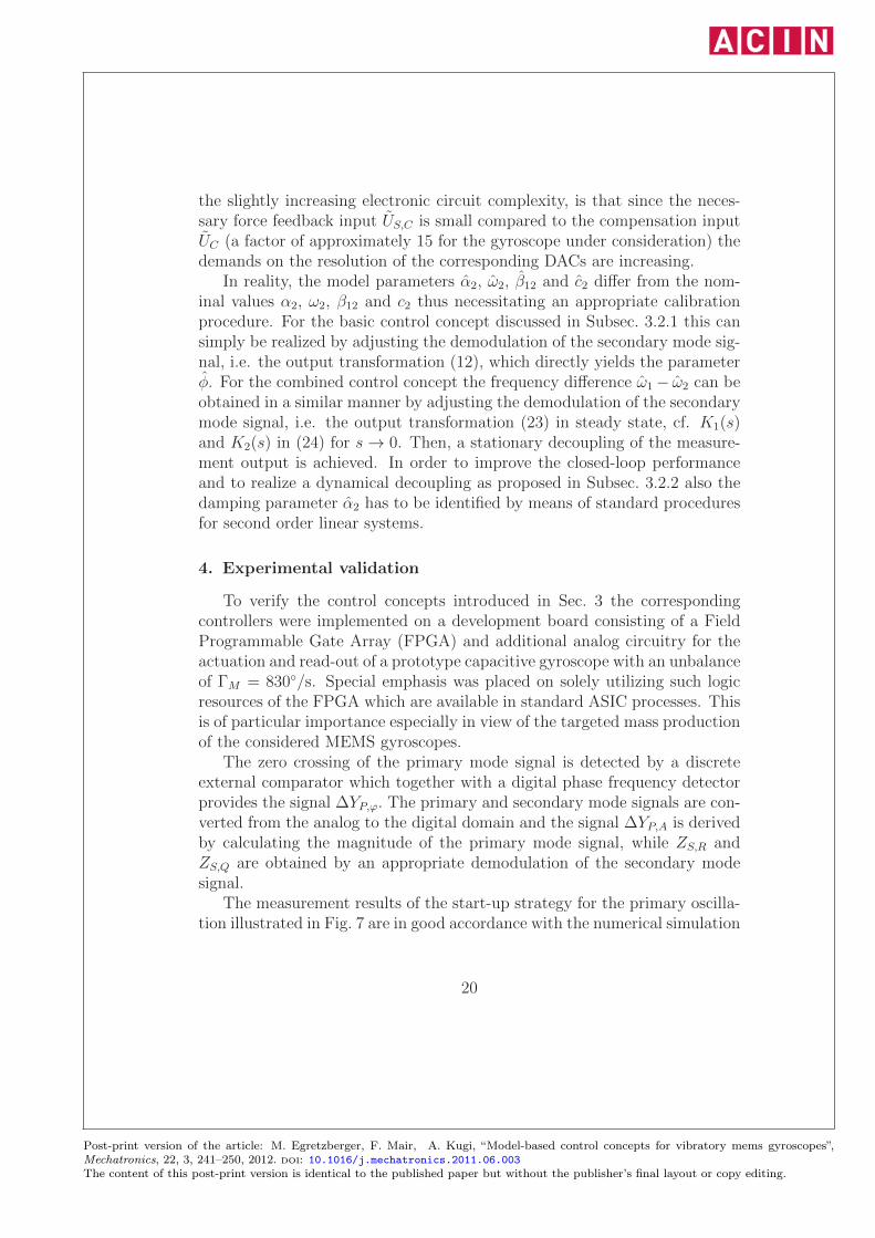
The measurement results of the start-up strategy for the primary oscilla-tion illustrated in Fig. 7 are in good accordance with the numerical simulation
20
Post-print version of the article: M. Egretzberger, F. Mair, A. Kugi, “Model-based control concepts for vibratory mems gyroscopes”,Mechatronics, 22, 3, 241–250, 2012. doi: 10.1016/j.mechatronics.2011.06.003The content of this post-print version is identical to the published paper but without the publisher’s final layout or copy editing.
1
t
tS tA
YP,A
0.250.150.05
0.8
0.6
0.4
0.3
0.2
0.20.100
(a) Amplitude
t
tS tA
UP,γ/U
P,m
ax
UP,0
UP,C
0.250.150.05
0.5
0.4
0.3
0.3
0.2
0.2
0.1
0.100
(b) Excitation voltage
t
tS tA
YP,ϕ
(rad)
ω/ω
1
YP,ϕ
ω/ω1
π/4
−π/4
−π/2
1.003
0.997
0.250.150.05 0.30.20.1
0
0
1
(c) Phase and excitation frequency
Figure 7: Measurement results of the start-up strategy for the primary mode in terms of(a) the normalized amplitude YP,A, (b) the voltages UP,γ , γ ∈ {0, C} and (c) the phaseYP,ϕ and the excitation frequency ω.
results presented in Sec. 3.1, cf. Fig. 4, and therefore validate the proposedmathematical model as well as the developed control concepts.
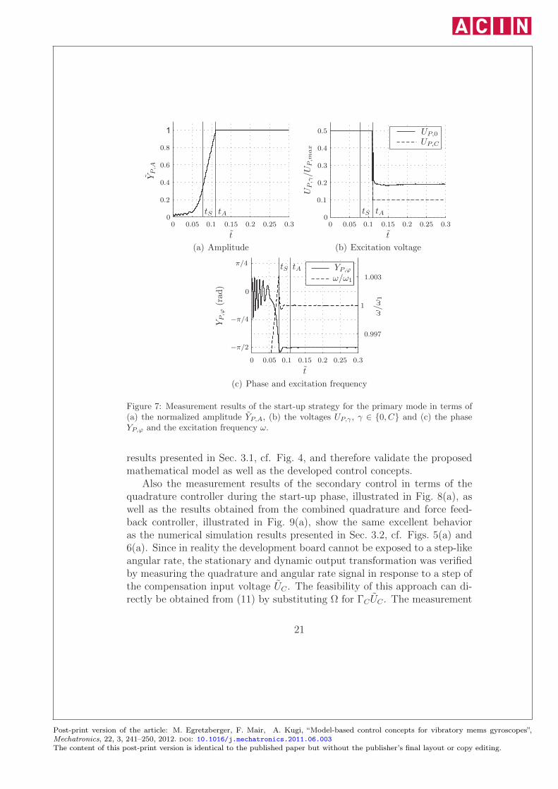
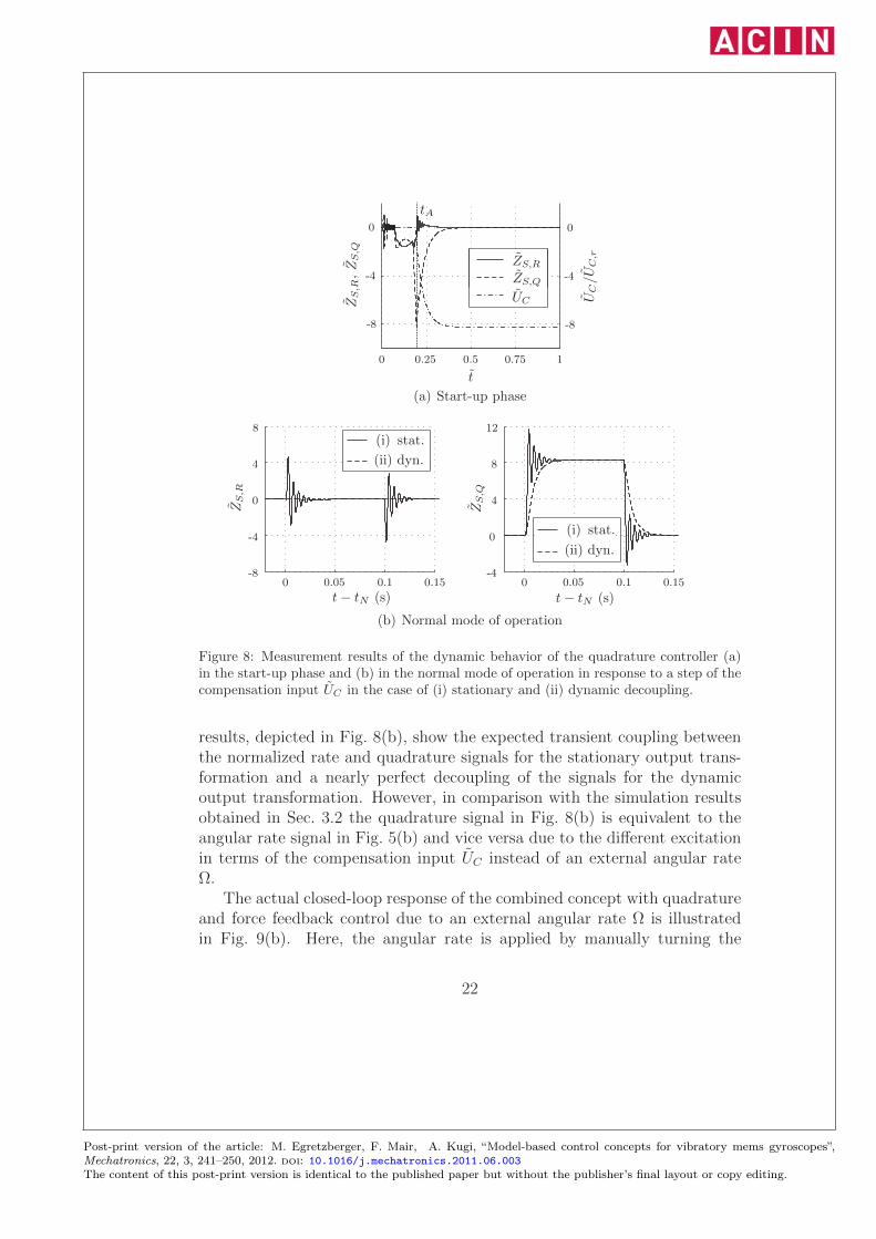
Also the measurement results of the secondary control in terms of thequadrature controller during the start-up phase, illustrated in Fig. 8(a), aswell as the results obtained from the combined quadrature and force feed-back controller, illustrated in Fig. 9(a), show the same excellent behavioras the numerical simulation results presented in Sec. 3.2, cf. Figs. 5(a) and6(a). Since in reality the development board cannot be exposed to a step-likeangular rate, the stationary and dynamic output transformation was verifiedby measuring the quadrature and angular rate signal in response to a step ofthe compensation input voltage UC . The feasibility of this approach can di-rectly be obtained from (11) by substituting Ω for ΓCUC . The measurement
21
Post-print version of the article: M. Egretzberger, F. Mair, A. Kugi, “Model-based control concepts for vibratory mems gyroscopes”,Mechatronics, 22, 3, 241–250, 2012. doi: 10.1016/j.mechatronics.2011.06.003The content of this post-print version is identical to the published paper but without the publisher’s final layout or copy editing.
t
tA
ZS,R,ZS,Q
ZS,R
ZS,Q
UC/U
C,r
UC
0 0.25 0.5 0.75 1
-8
-4
0
-8
-4
0
(a) Start-up phase
t− tN (s) t− tN (s)
ZS,R
ZS,Q
(i) stat.
(i) stat.
(ii) dyn.
(ii) dyn.
0 00.05 0.050.1 0.10.15 0.15-8
-4
-4
0
0
4
4
8
8
12
(b) Normal mode of operation
Figure 8: Measurement results of the dynamic behavior of the quadrature controller (a)in the start-up phase and (b) in the normal mode of operation in response to a step of thecompensation input UC in the case of (i) stationary and (ii) dynamic decoupling.
results, depicted in Fig. 8(b), show the expected transient coupling betweenthe normalized rate and quadrature signals for the stationary output trans-formation and a nearly perfect decoupling of the signals for the dynamicoutput transformation. However, in comparison with the simulation resultsobtained in Sec. 3.2 the quadrature signal in Fig. 8(b) is equivalent to theangular rate signal in Fig. 5(b) and vice versa due to the different excitationin terms of the compensation input UC instead of an external angular rateΩ.
The actual closed-loop response of the combined concept with quadratureand force feedback control due to an external angular rate Ω is illustratedin Fig. 9(b). Here, the angular rate is applied by manually turning the
22
Post-print version of the article: M. Egretzberger, F. Mair, A. Kugi, “Model-based control concepts for vibratory mems gyroscopes”,Mechatronics, 22, 3, 241–250, 2012. doi: 10.1016/j.mechatronics.2011.06.003The content of this post-print version is identical to the published paper but without the publisher’s final layout or copy editing.
t
tA
ZS,R,ZS,Q
ZS,R
ZS,Q
UC/U
C,r
UC
0 0.25 0.5 0.75 1
-8
-4
0
-8
-4
0
(a) Start-up phase
ZS,R,ZS,Q
Ωr(◦/s)
ΩrUS/U
C,r
US,CZS,R
ZS,Q
t− tN (s) t− tN (s)0 00.5 0.51 11.5 1.5
-0.04
-0.02-0.1
0 0
0.10.02
0.04
-100
-50
0
50
100
(b) Normal mode of operation
Figure 9: Measurement results of the dynamic behavior of the combined quadrature andforce feedback controller (a) in the start-up phase and (b) in the normal mode of operationin response to a manually applied external angular rate Ωr.
development board. The applied angular rate Ω is measured with a calibratedreference sensor yielding the measurement output Ωr. As can be observed,the normalized compensation input US,C is perfectly tracking the referenceΩr, whereas the angular rate and quadrature signals ZS,R and ZS,Q, remaindecoupled during the complete transition.
5. Summary
The paper presents a systematic design of open- and closed-loop con-trollers for vibratory MEMS gyroscopes based on so-called envelope models.As an illustrative example an optimized start-up strategy for the primarymode of a capacitive gyroscope is derived highlighting the advantages of the
23
Post-print version of the article: M. Egretzberger, F. Mair, A. Kugi, “Model-based control concepts for vibratory mems gyroscopes”,Mechatronics, 22, 3, 241–250, 2012. doi: 10.1016/j.mechatronics.2011.06.003The content of this post-print version is identical to the published paper but without the publisher’s final layout or copy editing.
presented methodology. Furthermore, the approach is also utilized for thesystematic design of a basic quadrature controller for the secondary modein order to compensate for the inherent unbalance effects caused by the nonideal fabrication process. In order to eliminate the typically weakly dampedopen-loop dynamics of the gyroscope and the transient coupling between thequadrature and the angular rate signal a more sophisticated combined con-cept of closed-loop quadrature and force feedback control was introduced.Simulation and measurement results for a prototype gyroscope validate themathematical models and prove the feasibility of the proposed control con-cepts.
Acknowledgements
This work was funded by the German BMBF as part of the EURIPIDESproject RESTLES (project no. V3EUR015).
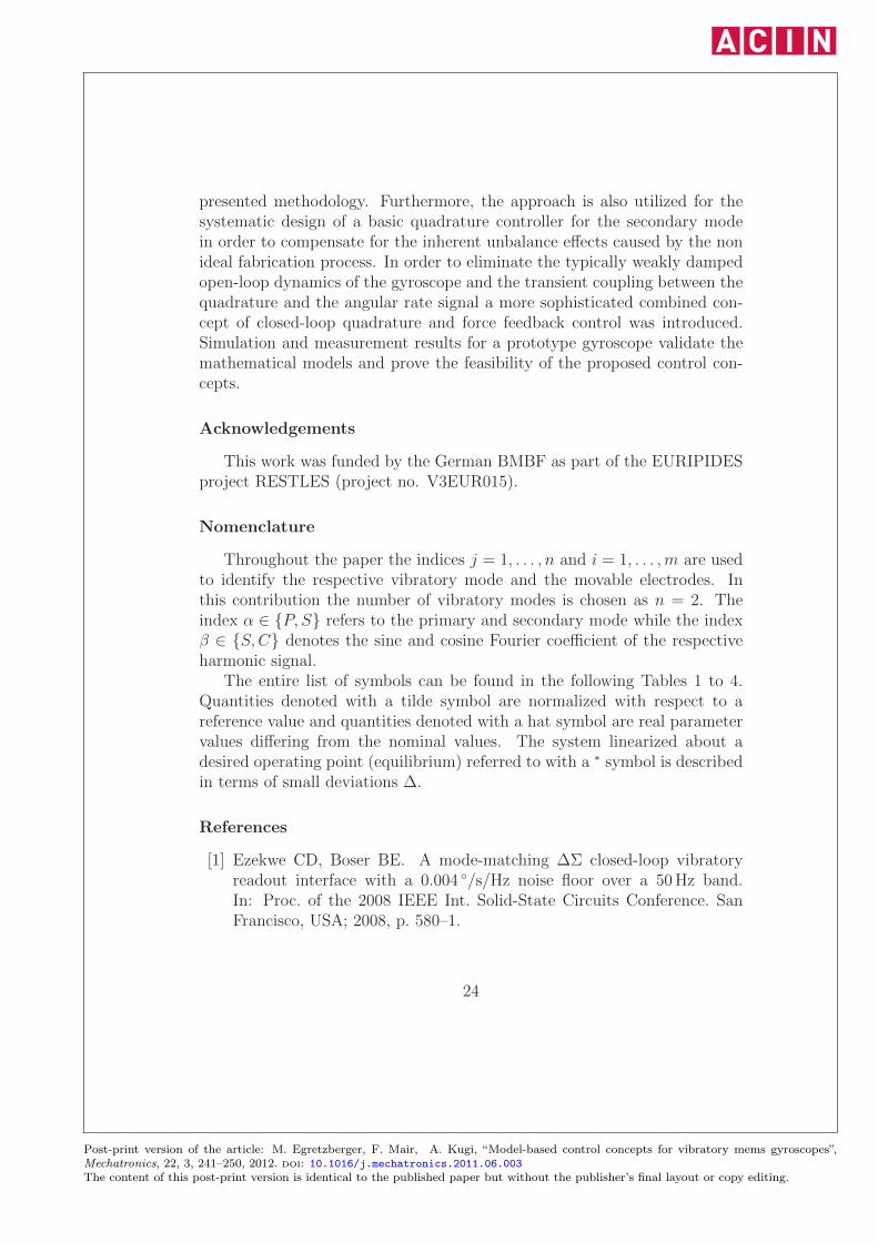
Nomenclature
Throughout the paper the indices j = 1, . . . , n and i = 1, . . . ,m are usedto identify the respective vibratory mode and the movable electrodes. Inthis contribution the number of vibratory modes is chosen as n = 2. Theindex α ∈ {P, S} refers to the primary and secondary mode while the indexβ ∈ {S,C} denotes the sine and cosine Fourier coefficient of the respectiveharmonic signal.
The entire list of symbols can be found in the following Tables 1 to 4.Quantities denoted with a tilde symbol are normalized with respect to areference value and quantities denoted with a hat symbol are real parametervalues differing from the nominal values. The system linearized about adesired operating point (equilibrium) referred to with a ∗ symbol is describedin terms of small deviations Δ.
References
[1] Ezekwe CD, Boser BE. A mode-matching ΔΣ closed-loop vibratoryreadout interface with a 0.004 ◦/s/Hz noise floor over a 50Hz band.In: Proc. of the 2008 IEEE Int. Solid-State Circuits Conference. SanFrancisco, USA; 2008, p. 580–1.
24
Post-print version of the article: M. Egretzberger, F. Mair, A. Kugi, “Model-based control concepts for vibratory mems gyroscopes”,Mechatronics, 22, 3, 241–250, 2012. doi: 10.1016/j.mechatronics.2011.06.003The content of this post-print version is identical to the published paper but without the publisher’s final layout or copy editing.
t Time
qj Vibratory modes
Ω, ξ Angular rate and side wall angle
mj , dj , kj Inertia, damping and stiffness coefficients
c12, k12, fj Coriolis, unbalance and electromechanical coupling coefficient
bj , k12,C , k2,T Input coefficients
cj Output coefficients
uP , uS,i Primary and secondary input voltages
xi, zi Translational degrees of freedom
ri, si Positive constants
gi, ti, Ai, li Gap, width, overlap area, overlap length
ε0, Ci, Wi Dielectric coefficient, capacitance and potential energy
uα, uC , uT Transformed input for harmonic excitation, unbalancecompensation and frequency tuning
yα Primary and secondary output voltage
Table 1: List of symbols concerning the general dynamical model.
[2] Kuisma H, Ryhanen T, Lahdenpera J, Punkka E, Routsalainen S,Silanpaa T, et al. A bulk micromachined angular rate sensor. In: Proc.of the 9th Int. Conf. on Solid-State Sensors, Actuators and Microsys-tems, Transducers ’97. Chicago, USA; 1997, p. 875–8.
[3] Loveday PW, Rogers CA. The influence of control system design on theperformance of vibratory gyroscopes. Journal of Sound and Vibration2002;255:417–32.
[4] Maenaka K, Fujita T, Konishi Y, Maeda M. Analysis of a highly sensitivesilicon gyroscope with cantilever beam as vibrating mass. Sensors andActuators A: Physical 1996;54:568–73.
[5] Geiger W, Butt WU, Gaißer A, Frech J, Braxmaier M, Link T, et al.Decoupled microgyros and the design principle DAVED. Sensors andActuators A: Physical 2002;95:239–49.
[6] Egretzberger M, Kugi A. A dynamical envelope model for vibratorygyroscopes. Microsystem Technologies 2010;16:777–86.
[7] Bhave SA, Seeger JI, Jiang X, Boser BE, Howe RT, Yasaitis J. Anintegrated vertical-drive, in-plane-sense microgyroscope. In: Proc. of
25
Post-print version of the article: M. Egretzberger, F. Mair, A. Kugi, “Model-based control concepts for vibratory mems gyroscopes”,Mechatronics, 22, 3, 241–250, 2012. doi: 10.1016/j.mechatronics.2011.06.003The content of this post-print version is identical to the published paper but without the publisher’s final layout or copy editing.
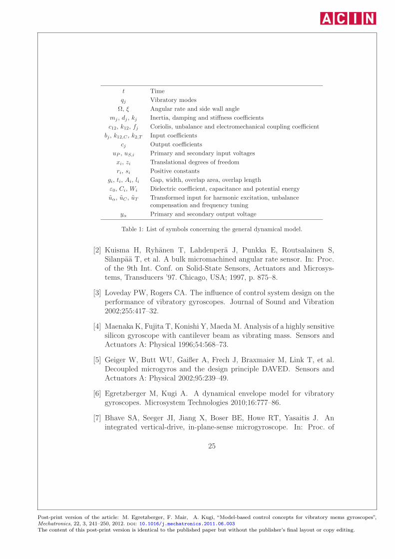
ω Excitation frequency
UP,0, UP,C Fourier coefficients of the primary excitation voltage
Qj,β Fourier coefficients of the vibratory modes
Uα,β Fourier coefficients of the harmonic inputs
UC , UT Fourier coefficients of the slowly varying inputs
Yα,1 Fourier coefficients of the output voltages
αj , βj , ωj Damping and input coefficients, eigenfrequencies
YP,A, YP,ϕ Amplitude and phase of the primary output voltage
YP,des Desired amplitude of the primary output voltage
β12, ΓF , ΓM , ΓC Input coefficients
ZS,R, ZS,Q Angular rate and quadrature output signal
Y, Z Output vectors
T Output transformation matrix
S Sensitivity
Table 2: List of symbols concerning the envelope model.
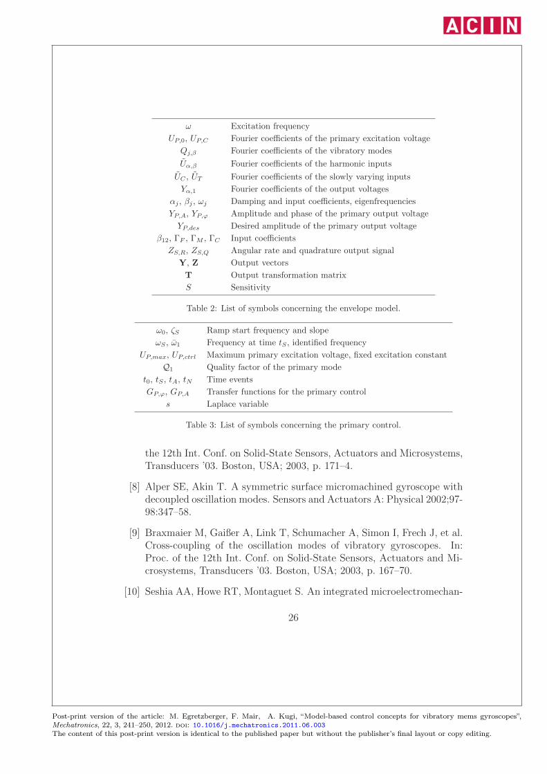
ω0, ζS Ramp start frequency and slope
ωS , ω1 Frequency at time tS , identified frequency
UP,max, UP,ctrl Maximum primary excitation voltage, fixed excitation constant
Q1 Quality factor of the primary mode
t0, tS , tA, tN Time events
GP,ϕ, GP,A Transfer functions for the primary control
s Laplace variable
Table 3: List of symbols concerning the primary control.
the 12th Int. Conf. on Solid-State Sensors, Actuators and Microsystems,Transducers ’03. Boston, USA; 2003, p. 171–4.
[8] Alper SE, Akin T. A symmetric surface micromachined gyroscope withdecoupled oscillation modes. Sensors and Actuators A: Physical 2002;97-98:347–58.
[9] Braxmaier M, Gaißer A, Link T, Schumacher A, Simon I, Frech J, et al.Cross-coupling of the oscillation modes of vibratory gyroscopes. In:Proc. of the 12th Int. Conf. on Solid-State Sensors, Actuators and Mi-crosystems, Transducers ’03. Boston, USA; 2003, p. 167–70.
[10] Seshia AA, Howe RT, Montaguet S. An integrated microelectromechan-
26
Post-print version of the article: M. Egretzberger, F. Mair, A. Kugi, “Model-based control concepts for vibratory mems gyroscopes”,Mechatronics, 22, 3, 241–250, 2012. doi: 10.1016/j.mechatronics.2011.06.003The content of this post-print version is identical to the published paper but without the publisher’s final layout or copy editing.
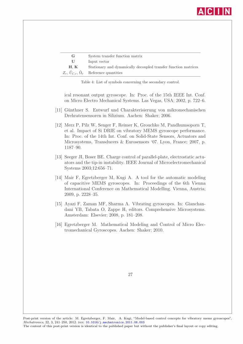
G System transfer function matrix
U Input vector
H, K Stationary and dynamically decoupled transfer function matrices
Zr, UC,r, Ωr Reference quantities
Table 4: List of symbols concerning the secondary control.
ical resonant output gyroscope. In: Proc. of the 15th IEEE Int. Conf.on Micro Electro Mechanical Systems. Las Vegas, USA; 2002, p. 722–6.
[11] Gunthner S. Entwurf und Charakterisierung von mikromechanischenDrehratensensoren in Silizium. Aachen: Shaker; 2006.
[12] Merz P, Pilz W, Senger F, Reimer K, Grouchko M, Pandhumsoporn T,et al. Impact of Si DRIE on vibratory MEMS gyroscope performance.In: Proc. of the 14th Int. Conf. on Solid-State Sensors, Actuators andMicrosystems, Transducers & Eurosensors ‘07. Lyon, France; 2007, p.1187–90.
[13] Seeger JI, Boser BE. Charge control of parallel-plate, electrostatic actu-ators and the tip-in instability. IEEE Journal of MicroelectromechanicalSystems 2003;12:656–71.
[14] Mair F, Egretzberger M, Kugi A. A tool for the automatic modelingof capacitive MEMS gyroscopes. In: Proceedings of the 6th ViennaInternational Conference on Mathematical Modelling. Vienna, Austria;2009, p. 2228–35.
[15] Ayazi F, Zaman MF, Sharma A. Vibrating gyroscopes. In: Gianchan-dani YB, Tabata O, Zappe H, editors. Comprehensive Microsystems.Amsterdam: Elsevier; 2008, p. 181–208.
[16] Egretzberger M. Mathematical Modeling and Control of Micro Elec-tromechanical Gyroscopes. Aachen: Shaker; 2010.
27
Post-print version of the article: M. Egretzberger, F. Mair, A. Kugi, “Model-based control concepts for vibratory mems gyroscopes”,Mechatronics, 22, 3, 241–250, 2012. doi: 10.1016/j.mechatronics.2011.06.003The content of this post-print version is identical to the published paper but without the publisher’s final layout or copy editing.
Related Documents
![New Adaptive Mode of Operation for MEMS Gyroscopes · The design and fabrication of MEMS gyroscopeshas been the subject of extensive ... performance [1,3]. Geometrical imperfections](https://static.cupdf.com/doc/110x72/5e8792413f321a69d3794297/new-adaptive-mode-of-operation-for-mems-gyroscopes-the-design-and-fabrication-of.jpg)