MODAL ANALYSIS OF DISSIMILAR METAL (STEEL AND ALUMINIUM) JOINT BY SPOT WLEDING MOHD FADHLI BIN CHE ISMAIL Report submitted in partial fulfilment of the requirements for the award of Bachelor of Mechanical Engineering Faculty of Mechanical Engineering UNIVERSITI MALAYSIA PAHANG JUNE 2013

Welcome message from author
This document is posted to help you gain knowledge. Please leave a comment to let me know what you think about it! Share it to your friends and learn new things together.
Transcript

MODAL ANALYSIS OF DISSIMILAR METAL (STEEL AND ALUMINIUM)
JOINT BY SPOT WLEDING
MOHD FADHLI BIN CHE ISMAIL
Report submitted in partial fulfilment of the requirements
for the award of Bachelor of Mechanical Engineering
Faculty of Mechanical Engineering
UNIVERSITI MALAYSIA PAHANG
JUNE 2013
vi
ABSTRACT
This project report deals with dynamic behaviour of joining between stainless steel and
aluminium alloy by Spot welding using theoretical and experimental analysis method.
The structural three-dimensional solid modelling of joining between stainless steel and
aluminium alloy by welding was developed using the drawing software. The finite
element model of the components was analysed using the linear modal analysis
approach. Finally, the experimental modal analysis was performed using Impact
Hammer Testing method. The natural frequency of the mode shape is determined and
comparative study was done from both method results. The comparison between natural
frequencies of finite element modelling and model testing shows the closeness of the
results. From the results, the percentage error had been determined and the limitation in
the natural frequency of the joining between stainless steel and aluminium alloy by
welding is observed. The results of this project shown the mode shape of the joining
plate by Spot welding for simulation are generally is not in agreement with the
experimental value and the frequencies of the experimental modal analysis are a bit
different with the frequencies of the simulation. The percentage error is bit high because
there are some errors occur during the experimental modal analysis. The experimental
modal analysis is conducted with fix condition of the joining plate between aluminium
alloy and stainless steel by welding and the effect of damping which effect test rig by
using polystyrene as a base of the plate is a factors as the higher percentage error. It is
conclude that the in experimental method uses the polystyrene as a base affected the
result. Experimental operating deflection shape also conducted and compare with
calculation method to get a dominant mode shape when 53.3 Hz will give. Mode one
show a dominant mode in ods. The result shows joining between aluminium and steel
by Spot drawn to welding–brazing because of their difference in melting point and the
natural frequency comparison shows the closeness of the result between experimental
modal analysis and FEA.

vii
ABSTRAK
Laporan projek ini berkaitan dengan perilaku dinamik sambungan plate antara
aluminium aloi dan keluli tahan karat oleh kimpalan menggunakan kaedah analisis teori
dan eksperimen. Pemodelan struktur tiga-dimensi spiral wound gasket dilukis
menggunakan perisian melukis. Analisis di dalam perisian ini menggunakan pendekatan
analisis linier modal. Kemudian, analisis modal secara eksperimen dilakukan dengan
menggunakan kaedah kesan ketukan. Frekuensi dan bentuk mod ditentukan dan kajian
perbandingan dilakukan dari kedua-dua keputusan kaedah. Perbandingan antara
frekuensi dari pemodelan elemen secara teori dan ujian model secara eksperimen
menunjukkan keputusan yang hampir sama. Dari hasil tersebut, peratus perbezaan
antara kedua kaedah telah direkod dan had frekuensi asas sambungan plate antara
aluminium aloi dan keluli tahan karat oleh kimpalan telah diamati. Keputusan projek ini
telah menunjukkan bahawa bentuk mod sambungan plate oleh kimpalan Spot bagi
simulasi secara umumnya adalah tidak sama dengan nilai eksperimen dan frekuensi
analisis ragaman eksperimen adalah agak berbeza dengan frekuensi simulasi. Peratus
ralat agak tinggi kerana terdapat beberapa kesilapan berlaku semasa eksperimen.
eksperimen dijalankan dengan keadaan tetap bagi sambungan plate antara aluminium
aloi dan keluli tahan karat oleh kimpalan dengan menggunakan polistirena sebagai
pelapit plate dan memberi kesan redaman berlaku. Ia menyimpulkan bahawa dalam
kaedah eksperimen, penggunaan polistirena sebagai pelapit memberi kesan terhadap
result. Eksperimen bentuk pesongan operasi dijalankan dan di bandingkan dengan
keputusan cara pengiraan untuk mendapatkan bentuk mod yang dominan apabila 53.3
Hz dikenakan. Mod pertama menunjukkan mod dominan apabila menbuat eksperimen
bentuk pesongan. Hasil menunjukkan antara aluminium dan keluli oleh Spot tertarik
dengan kimpalan pateri kerana perbezaan mereka dalam takat lebur dan perbandingan
kekerapan semula jadi menunjukkan keakraban antara hasil analisis eksperimen modal
dan FEA

viii
TABLE OF CONTENTS
Page
SUPERVISOR’S DECLARATION ii
STUDENT’S DECLARATION iii
ACKNOWLEDGEMENTS v
ABSTRACT vi
ABSTRAK vii
TABLE OF CONTENTS viii
LIST OF TABLE xi
LIST OF FIGURES xii
LIST OF SYMBOLS xv
LIST OF ABBREVIATIONS xvi
CHAPTER 1 INTRODUCTION
1.1 Introduction 1
1.2 Project Objectives 1
1.3 Project Scopes 2
1.4 Problem Statement 2
CHAPTER 2 LITERATURE REVIEW
2.1 Introduction 3
2.2 Basic Vibration Theory 3
2.3 Modal Testing
2.3.1 Parameters of Modal Testing
4
6
2.4 Welding
2.4.1 Consideration of Welding
7
7
2.5 Spot Welding 8
2.5.1 Principles of Spot Welding
2.5.2 Advantages of Spot Welding
2.5.3 Disadvantages of Spot Welding
9
10
10

ix
2.6 Material 11
2.6.1 Aluminium Alloy 1100 11
2.6.2 Stainless Steel SUS30 12
2.7 Finite Element Analysis System 12
2.7.1 Advantages of Finite Element Analysis
2.7.2 Disadvantages of Finite Element Analysis
13
13
CHAPTER 3 METHODOLOGY
3.1 Introduction 15
3.2 Material 17
3.2.1 Aluminium Alloy 1100 17
3.2.2 Stainless Steel SUS30 17
3.3 Method Welding 18
3.4 Modelling 19
3.4.1 Modelling Method 19
3.5 Simulation 20
3.5.1 Simulation Method 20
3.5.2 Meshing 21
3.6 Modal Testing 22
3.6.1 Impact Hammer Testing 22
3.6.2 Modal Analysis Procedures 23
3.6.3 Step of Experimental Modal Analysis
3.7 Experimental Operating Deflection Shape
3.7.1 Calculation for Operating Deflection Shape
24
27
28
CHAPTER 4 RESULT AND DISCUSSION
4.1 Introduction 30
4.2 Result Of Joining Between Aluminium Alloy And Stainless
Steel (SPOT Welding)
30
4.3 Result Of Natural Frequency 32
4.3.1 Natural Frequency Of Finite Element Analysis (FEA) 32
4.3.2 Natural Frequency Of Experimental Modal Analysis 33
4.3.3 Comparison of Natural Frequency Between FEA and 34

x
Experimental Modal Analysis
4.4 Result Of Mode Shapes 35
4.4.1 Mode Shapes Of ANSYS Finite Element Analysis 36
4.4.2 Mode Shapes Of Experimental Analysis 36
4.5 Comparison Of Mode Shapes Between FEA And
Experimental Modal Analysis
36
4.5.1 Result of Stainless Steel Plate 37
4.5.2 Result of Aluminium Alloy Plate 42
4.5.3 Result of Joining Plate between Stainless Steel and
Aluminium Alloy
4.6 Comparison of Mode Shapes Between Calculation And
Experimental Operating Deflection Shape
4.7 Discussion of Comparison
47
52
56
CHAPTER 5 CONCLUSIONS
5.1 Introduction 59
5.2 Conclusions 59
5.3 Recommendations 60
REFERENCES 61
APPENDICES
A1 Chemical Composition Of The Aluminium Alloy 1100 H14
Sheets
63
A2 Chemical Composition Of The Stainless Steel Aisi 304 Sheets 64
xi
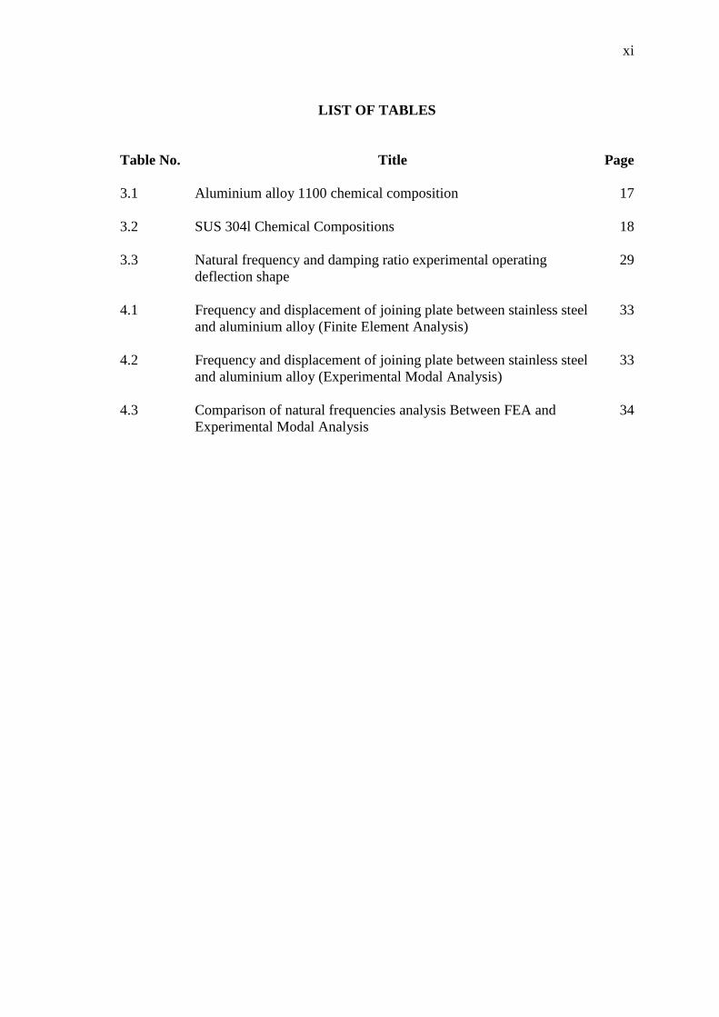
LIST OF TABLES
Table No. Title Page
3.1 Aluminium alloy 1100 chemical composition 17
3.2
3.3
SUS 304l Chemical Compositions
Natural frequency and damping ratio experimental operating
deflection shape
18
29
4.1 Frequency and displacement of joining plate between stainless steel
and aluminium alloy (Finite Element Analysis)
33
4.2 Frequency and displacement of joining plate between stainless steel
and aluminium alloy (Experimental Modal Analysis)
33
4.3 Comparison of natural frequencies analysis Between FEA and
Experimental Modal Analysis
34
xii
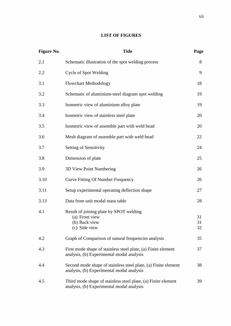
LIST OF FIGURES
Figure No. Title Page
2.1 Schematic illustration of the spot welding process 8
2.2 Cycle of Spot Welding 9
3.1 Flowchart Methodology 18
3.2 Schematic of aluminium-steel diagram spot welding 19
3.3 Isometric view of aluminium alloy plate 19
3.4 Isometric view of stainless steel plate 20
3.5 Isometric view of assemble part with weld bead 20
3.6 Mesh diagram of assemble part with weld bead 22
3.7 Setting of Sensitivity 24
3.8 Dimension of plate 25
3.9 3D View Point Numbering 26
3.10
3.11
3.13
Curve Fitting Of Number Frequency
Setup experimental operating deflection shape
Data from unit modal mass table
26
27
28
4.1 Result of joining plate by SPOT welding
(a) Front view
(b) Back view
(c) Side view
31
31
32
4.2 Graph of Comparison of natural frequencies analysis 35
4.3 First mode shape of stainless steel plate, (a) Finite element
analysis, (b) Experimental modal analysis
37
4.4 Second mode shape of stainless steel plate, (a) Finite element
analysis, (b) Experimental modal analysis
38
4.5 Third mode shape of stainless steel plate, (a) Finite element
analysis, (b) Experimental modal analysis
39
xiii
4.6 Fourth mode shape of stainless steel plate, (a) Finite element
analysis, (b) Experimental modal analysis
40
4.7 Fifth mode shape of stainless steel plate, (a) Finite element
analysis, (b) Experimental modal analysis
41
4.8 First mode shape of aluminium alloy plate, (a) Finite element
analysis, (b) Experimental modal analysis
42
4.9 Second mode shape of aluminium alloy plate, (a) Finite element
analysis, (b) Experimental modal analysis
43
4.10 Third mode shape of aluminium alloy plate, (a) Finite element
analysis, (b) Experimental modal analysis
44
4.11 Fourth mode shape of aluminium alloy plate, (a) Finite element
analysis, (b) Experimental modal analysis
45
4.12 Fifth mode shape of aluminium alloy plate, (a) Finite element
analysis, (b) Experimental modal analysis
46
4.13 First mode shape of joining plate by SPOT welding,
(a) Finite element analysis, (b) Experimental modal analysis
47
4.14 Second mode shape of joining plate by SPOT welding,
(a) Finite element analysis, (b) Experimental modal analysis
48
4.15 Third mode shape of joining plate by SPOT welding,
(a) Finite element analysis, (b) Experimental modal analysis
49
4.16 Fourth mode shape of joining plate by SPOT welding,
(a) Finite element analysis, (b) Experimental modal analysis
50
4.17
4.18
Fifth mode shape of joining plate by SPOT welding,
(a) Finite element analysis, (b) Experimental modal analysis
First mode shape of Operating Deflection Shape,
(a) Calculation, (b) ME Scope
51
52
4.19
4.20
4.21
4.22
Second mode shape of Operating Deflection Shape,
(a) Calculation, (b) ME Scope
Third mode shape of Operating Deflection Shape,
(a) Calculation, (b) ME Scope
Fourth mode shape of Operating Deflection Shape,
(a) Calculation, (b) ME Scope
Graph comparison mode shape in ODS with calculation
53
54
55
56

xiv
LIST OF SYMBOLS
ºC
Psi
Degree Celsius
Pounds per Square Inch
w Watt
A Ampere
mm Millimetre
min Minute
N Newton
% Per cent
volt Voltan
Hz Hertz
Al Aluminium
Zn Zink
Si Silicone
Cu Cuprum
Mg Magnesium
Cr Chromium
Ni Nickel
Mn Mangan
C Carbon
xv
LIST OF ABBREVIATIONS
RSW Resistance Spot Welding
IMC Intermetallic Compounds
NVH Noise, Vibration And Hardness
FEA Finite Element Analysis
FEM Finite Element Method
DOF Degree Of Freedom
SDOF Single Degree Of Freedom
MDOF Multi Degree Of Freedom
FRF Frequency Response Function
DAS Data Acquisition System
CAD Computer Aided Diagram
IGES Initial Graphics Exchange Specification
FFT Fast Fourier Transform
2D Two Dimensional
3D Three Dimensional
ASCII American Standard Code for Information Interchange
SI
Br
Xr
Xpr
Qpr
Q
International System of Units
Magnitude transfer function
Respond for spatial (couple)
Respond in modal
Force for modal
Force
1
CHAPTER 1
INTRODUCTION
1.1 GENERAL INTRODUCTION
Steel and aluminium are the most important construction materials for the mass
production of today’s automotive structures. It is well known that metallurgical bonds
between aluminium and steel are difficult to achieve with fusion welding because of the
inherent discrepancies in electrical, thermal, and mechanical properties between the two
materials. For fusion welding processes such as direct resistance spot welding (RSW),
little or no mutual solubility of aluminium and steel exists. The most common
application of spot welding is in the automobile industry used to weld the sheet metal
form a body car and other parts.
In this project, it will investigate the stability and detect the vibration that
occurred in the dissimilar metal joint by Spot welding using different thickness. The
vibration occurred is obtained by performing dynamic analysis using Finite Element
Analysis (FEA).
1.2 PROJECT OBJECTIVE
The purpose of this research is to study the dynamic properties and behaviour of
dissimilar metal (Steel and Aluminium) joint by spot welding using modal analysis and
comparison with the finite element analysis.
2
1.3 PROJECT SCOPE
This project focuses on the following points:
i. Welding dissimilar metal with different thickness.
ii. The specimen product metal is created using SOLIDWORK.
iii. The theoretical data for dynamic analysis using FEA will be taken.
iv. To develop FEA analytical simulation method and experimental modal analysis
to compare the result
v. Check dominant mode shape using Operating Deflection Shape
1.4 PROBLEM STATEMENT
Hybrid structures of aluminium alloy to stainless steel are suggested in
spacecraft, airplane and automotive to improve the fuel efficiency, increase the fly range
by reducing weight. Therefore, it is receiving a remarkable attention to joining
aluminium alloy and stainless steel together. However, aluminium and steel are not
compatible metals as far as fusion welding. Modal analysis was done to obtain the
actual dynamic properties. The dynamic properties which consist of natural frequency,
mode shape and damping are unknown on the design. The frequency of vibration of the
dissimilar metal joint by spot welding using different thickness is directly related to the
stiffness and the mass of it while the mode shapes are related to the defect location.
Therefore, vibration testing needs to be carried out to obtain the data of those dynamic
properties.

3
CHAPTER 2
LITERATURE REVIEW
2.1 INTRODUCTION
This chapter presents the review of the modal analysis of dissimilar metal (steel
and aluminium) joint by using spot welding. This chapter begins with general review of
processes by given a simple definition of the key terms and, the importance and to make
a modal testing. Reviews of some of the previous works that are similar and related to
this study are discussed in this chapter.
2.2 BASIC VIBRATION THEORY
Any system has certain characteristics that must be met before it will vibrate. In
simple words, each system has a stable position in which all teams are equal, and when
this balance is disturbed, the system will try to regain a stable position. To maintain a
stable, vibration exhibits structure at different magnitudes when excited, the vibration
varies from point to point (node to node), due to changes in the structure and dynamic
response of the external force applied. Therefore, the vibration can also be described as
the physical manifestation of the exchange between kinetic and potential energy (Silva,
2005).
4
All vibration is a combination of both forced and resonant vibration. Forced
vibration can be due to,
· Internally generated forces.
· Unbalances.
· External loads.
· Ambient excitation.
Resonant vibration occurs when one or more of the resonances or natural modes
of vibration of a machine or structure is excited. Resonant vibration typically amplifies
the vibration response far beyond the level deflection, stress, and strain caused by static
loading (Schwarz B.J and Richardson M.H, 1999)
2.3 MODAL TESTING
Modal testing is a formalized method for identification of natural frequencies
and mode shapes of structures. It utilizes dedicated modal test equipment, and requires a
formalized procedure for disturbing, e.g., rapping, the structure into motion, and then
recording the distribution of the resulting motions throughout the structure. The end
results of a modal test are the various natural frequencies, mode shapes, and impedance
data of the structure. These data are identified from the digitized input signals using
efficient curve-fitting routines. The results are subsequently displayed as impedance
plots and mode shapes. (Rieger N.F, 2003)
Modal testing is used to rapidly identify these modes and their natural
frequencies, and to provide the structural matrices, which govern the modes and natural
frequencies. The advantages of modal analysis that are a modal test provides the most
rapid and effective procedure available for the acquisition of data on the dynamic
properties of a structure. Second advantage, modal analysis is an effective analytical
procedure for the solution of large sets of structural dynamics equations because it
reduces coupled matrix equations to a set of independent linear equations. Modal
solutions can therefore be obtained directly, without further numerical operations. These
solutions are then re-combined to form the complete solution to the structural response

5
problem in question. It should here be noted that solutions to harmonic, transient, and
random forced vibration problems can all be obtained using this modal analytical
procedure. (Rieger N.F, 2003)
According (Rieger N.F, 2003), the output from modal testing consists of natural
frequencies, mode shapes, modal stiffness, modal damping, and modal mass matrices.
The main assumption involved in the acquisition of this information is that the structural
system is linear, i.e., structural displacements are directly proportional to applied loads.
In practical structures this condition is not always met. Structural systems may be non-
linear to some degree, due to those causes listed below. Nonlinearities complicate the
extraction of modal data and, where their effect is strong; they may invalidate the results
obtained by linear analysis. Non-linear effects may be present in a structural system due
to several causes:
i. The material properties may be non-linear, e.g., composite structures,
viscoelastic materials, elastic-plastic materials, where displacement is non-
linearly related to force.
ii. Where large amplitudes are involved, the geometry may result in displacements,
which are non-linearly related to load, e.g., large deflections of plate and shell-
type structures.
iii. The structural boundary conditions may introduce nonlinearities, e.g., structures
where the number of support points changes, or where the structure is a rotor
mounted in fluid-film bearings experiencing relatively large whirl amplitudes.
Another limitation of modal testing is that it cannot, by itself, predict threshold
conditions for structural stability problems, such as structural buckling, and rotor whirl
stability in fluid-film bearings.
Again, the modal test structural matrix data from such problems can be
developed for subsequent (linear) finite element analysis, such as the prediction of
stability threshold conditions. However, the nonlinear limitation again applies to the
6
post- threshold behaviour of such structures. Following the development of an unstable
condition, e.g., buckling or rotor whirl, the structure characteristically undergoes large
displacements until a new equilibrium condition is found. Such behaviour may be
highly non-linear, and so beyond the capabilities of modal analysis, and of the structural
matrices developed by modal testing. (Rieger N.F, 2003)
2.3.1 Parameters of Modal Testing
The parameters that describe each mode are:
i. natural frequency or resonance frequency
ii. (modal) damping
iii. mode shape
These are called the modal parameters. By using the modal parameters to model
the structure, vibration problems caused by these resonances (modes) can be examined
and understood. In addition, the model can subsequently be used to come up with
possible solutions to individual problems. The modal parameters can be extracted from
a set of Frequency Response Function (FRF) measurements between one or more
reference positions and a number of measurement positions required in the model. A
position is a point and a direction on the structure and is hereafter called a Degree of
Freedom (DOF). The resonance frequencies and damping values can be found from any
of the FRF measurements on the structure (except those for which the excitation or
response DOF is in a nodal position, that is, where the mode shape is zero). These two
modal parameters are therefore called ‘Global Parameters’. To accurately model the
associated mode shape, frequency response measurements must be made over a
sufficient number of DOFs to ensure enough detailed coverage of the structure under
test. The extraction of the modal parameters from the FRFs can be done using a variety
of mathematical curve-fitting algorithms. In order to calibrate (scale) the modal model,
the driving-point measurement, the measurement where the excitation and the response
is in the same DOF, needs to be included. (Herlufsen .H, Denmark)

7
2.4 WELDING
Aluminium and steel joined by fusion welding is difficult because the compound
is a mixture of two compounds form a brittle intermetallic compounds (IMCs) in the
joints. To control the formation of the IMC layer, the shape and size of the joint is very
important. Joints have two features: the base, aluminium alloy metal with low melting
weld together, mixed with molten filler metal to form a weld joint, while steel is a metal
surface with a high melting point solder, which acts as the reaction with the filler metal
liquid to form a solder layer interface formed solder joints. (Lin et al., 2009)
Joining of aluminium alloy and stainless steel can be difficult for non-metallic
aluminium and steel fusion welding as far as appropriate. The reason for this is due to
the large difference between the melting point (660 ° C for Al and 1538 º C to Fe), close
to zero solid solubility of aluminium metal, and the formation of brittle intermetallic
compounds. The difference in the thermal properties of the two materials, such as
expansion coefficient, conductivity, and specific heat leads to internal stresses after
fusion welding. (Song et al., 2009)
2.4.1 Consideration of Welding
i. Size installation: For a large gathering, welding is a more appropriate method.
Larger gatherings require high heat during solder heating requires less heat,
making it difficult to reach the required temperature filler metal flow.
ii. Thickness: To participate in a thin sheet, solder has the advantage of high heat
such as welding can wrap or burn through that section. Instead, solder can help
to avoid distortion.
iii. Form joints: more welding saves time and cost. In addition, the solder just as
easily draw the filler metal into the weld configuration straight, curved or
irregular.

8
iv. Type of material: welding solder soundly beats when joining dissimilar metals.
As long as the filler material is compatible with both the base metal and melts at
a lower temperature, solder joints can make a sound. In contrast, thin base
material during welding to join two dissimilar metals using this method can
involve complex and expensive techniques.
2.5 SPOT WELDING
Resistance spot welding is one of the oldest electric welding processes in use by
industry today, especially in the automotive industry. Welds made by a combination of
heat, pressure, and time. As the name resistance welding implies, it is the resistance of
the material to be welded to current flow causes localized heating in parts. The pressure
exerted by the tongs and electrode tips, in which the current flows, holds the parts to be
welded in intimate relationships before, during, and after the welding cycle. The amount
needed during the course of time in the joint is determined by the thickness and type of
material, the total running time, and the cross sectional area of the surface of the
welding contact tip. (Handbook for Resistance Spot Welding, 2012)
Figure 2.1: Schematic view of the spot welding process
Source: Thakur et al., (2010)
9
2.5.1 Principles of Spot Welding
Resistance welding is accomplished when current is caused to flow through
electrode tips and the separate pieces of metal to be joined. The resistance of the base
metal to electrical current flow causes localized heating in the joint, and the weld is
made. The resistance spot weld is unique because the actual weld nugget is formed
internally in relation to the surface of the base metal. (Handbook for Resistance Spot
Welding, 2012)
In the spot welding process, two or three overlapped or stacked stamped
components are welded together as a result of the heat created by electrical resistance.
This is provided by the work pieces as they are weld together under pressure between
two electrodes. Spot welding may be performed manually, robotically or by a dedicated
spot welding machine. The similar spot welds having same property can be obtained in
high production speeds by controlling welding current, electrode force and weld time
automatically.
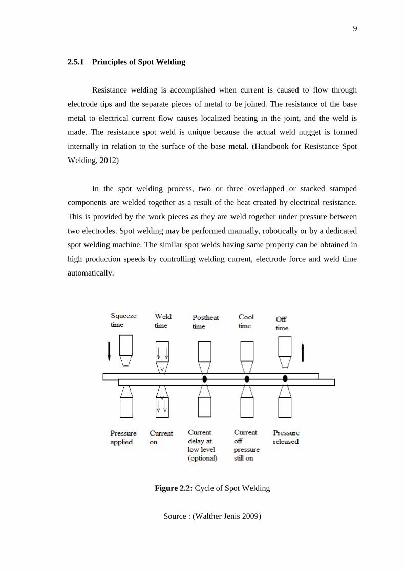
Figure 2.2: Cycle of Spot Welding
Source : (Walther Jenis 2009)
10
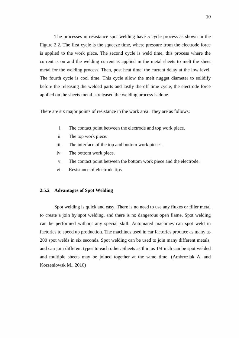
The processes in resistance spot welding have 5 cycle process as shown in the
Figure 2.2. The first cycle is the squeeze time, where pressure from the electrode force
is applied to the work piece. The second cycle is weld time, this process where the
current is on and the welding current is applied in the metal sheets to melt the sheet
metal for the welding process. Then, post heat time, the current delay at the low level.
The fourth cycle is cool time. This cycle allow the melt nugget diameter to solidify
before the releasing the welded parts and lastly the off time cycle, the electrode force
applied on the sheets metal is released the welding process is done.
There are six major points of resistance in the work area. They are as follows:
i. The contact point between the electrode and top work piece.
ii. The top work piece.
iii. The interface of the top and bottom work pieces.
iv. The bottom work piece.
v. The contact point between the bottom work piece and the electrode.
vi. Resistance of electrode tips.
2.5.2 Advantages of Spot Welding
Spot welding is quick and easy. There is no need to use any fluxes or filler metal
to create a join by spot welding, and there is no dangerous open flame. Spot welding
can be performed without any special skill. Automated machines can spot weld in
factories to speed up production. The machines used in car factories produce as many as
200 spot welds in six seconds. Spot welding can be used to join many different metals,
and can join different types to each other. Sheets as thin as 1/4 inch can be spot welded
and multiple sheets may be joined together at the same time. (Ambroziak A. and
Korzeniowsk M., 2010)
11
2.5.3 Disadvantages of Spot Welding.
The electrodes have to be able to reach both sides of the pieces of metal that are
being joined together. A particular spot welding machine will be able to hold only a
certain thickness of metal--usually 5 to 50 inches--and although the position of the
electrodes can be adjusted, there will be only a limited amount of movement in most
electrode holders.
The size and shapes of the electrodes will determine the size and strength of the
weld. The join forms only at the spot where the electrodes are in contact with the metal.
If the current is not strong enough, hot enough or the metal is not held together with
enough force, the spot weld may be small or weak.
Warping and a loss of fatigue strength can occur around the point where metal
has been spot welded. The appearance of the join is often rather ugly, and there can be
cracks. The metal may also become less resistant to corrosion. (Ambroziak A. and
Korzeniowsk M., 2010).
2.6 MATERIAL
2.6.1 Aluminium Alloy 1100
Aluminium alloy 1100 contains at least 99% aluminium. It has excellent
electrical conductivity, good formability and high corrosion resistance, and is used
where high strength is required. It has a low density and excellent thermal conductivity
normal to all aluminium alloys. Pieces of aluminium alloys have moderate strength and
light weight. Aluminium alloy 1100 can be welded by gas welded or resistance welded,
but the resulting joints are not strong or corrosion resistant as the inert gas welded
joints. (Austral Bronze Crane Copper Limited, 2005)
According (Beneke Wire Company) it has at least 99.0% of aluminium, not heat
treated alloy also known as commercially pure aluminium. This alloy combines
excellent formability and corrosion resistance is very high to be used in many
12
applications where high strength is not required. These alloys can be used in most any
climate anywhere without worry. Anodizing very good finish can be obtained,
especially with special finishes listed below.
2.6.2 Stainless Steel SUS304
Stainless steel SUS304 with chemical composition: 18.52Cr- 8.34Ni- 0.42Si
0.89Mn- 0.046C- 0.002P- 0.002S in percent weight.Class austenitic stainless steel is
generally considered be weld able by the common fusion and resistance techniques.
Special consideration is required to avoid weld "hot cracking" to ensure the formation
of ferrite in the weld deposit. Type 304 and 304L are generally considered to be most
common alloy is class steel.
SUS304 stainless steel is the basic evolution of austenitic stainless steel. It have
good corrosion resistance, heat resistance, low temperature strength and mechanical
properties, thermal processing, such as stamps, good treatment and non-hardening
flexible heat. For welding thin-walled, SUS304 stainless steel is widely used. For
welding of stainless steel SUS304 is good without heat treatment after welding, welding
methods can determine the thickness and only 2mm should be applied in the welding
material, medium plate submerged arc welding can be used.
2.7 FINITE ELEMENT ANALYSIS SYSTEM
Finite element analysis is a computerized procedure for the analysis of
structures. Rapid engineering analyses can be performed because the structure is
represented (modelled) using the known properties of standard geometric and the finite
element method.
In order to use the FEM model with confidence, it has been found necessary to
verify the accuracy of the model by comparing the modal parameters (frequency,
damping and mode shapes) are predicted by the model cap parameters identified by
actually testing the structure. In fact, most progress in experimental modal test comes
from demand to verify the accuracy of FEM model. (Ramsey K.A., 1983)
13
Finite element analysis used in this manner provides the dynamic properties of
structures, including mode shapes and corresponding natural frequencies. (Rieger N.F.
2003). The finite element method (FEM) has been used extensively to predict residual
stress in welding repairs. (Jiang et al., 2010)
2.7.1 Advantages of Finite Element Analysis
Finite Element Analysis of the digital computer enables effective
problem solving and complex problems in structural dynamics. Structural
dynamics can be solved in the frequency domain using the transformation of
the modal. Finite element computer code efficiently performs structural
dynamic response calculations involving harmonic response, transient
response and random structure of the complex. Therefore, the finite element
method offers a highly efficient procedure for the calculation of complex
linear structures under dynamic excitation conditions variables. (Rieger N.F.
2003). According to Ramsey (1983), the advantage of finite element is
i. The model can be “built and used before any prototype hardware is available.
ii. The model can predict a structure’s behaviour under real world dynamic
operating conditions.
iii. An engineer can analytically modify the structure (via the FEM model) much
cheaper, faster and easier than he can change actual hardware.
2.7.2 Disadvantages of Finite Element Analysis
Although the problem of linear structural dynamics may now complete
accurately and economically, it is still expensive to solve most non-linear problems.
Problem of repetitive geometry is quite common, for example, bladed turbo machinery
structures, axisymmetric structure, the structure of the building, and many types of
rotating machinery. Geometric often closes on its own structure ('ring' structure). Total
structure matrix is still symmetric and three diagonal, but the dynamic matrix contains
off-diagonal elements, which can significantly increase local bandwidth matrix. This
causes a corresponding increase in computational time. Efficient Calculation of
Related Documents