TECHNICAL REPORT RDMR-SS-13-13 MISSILE DESIGN TOOL (MDT) USER’S GUIDE Andrew Watts, Sam Curtis, John Braswell, and Mark Underwood System Simulation and Development Directorate Aviation and Missile Research, Development, and Engineering Center February 2014 Distribution Statement A: Approved for public release; distribution is unlimited.

Welcome message from author
This document is posted to help you gain knowledge. Please leave a comment to let me know what you think about it! Share it to your friends and learn new things together.
Transcript
TECHNICAL REPORT RDMR-SS-13-13
MMIISSSSILLEE DDEESIIGGNN TTOOOLL ((MMDDTT))
UUSSEERR’’SS GGUUIIDDEE
Andrew Watts, Sam Curtis, John Braswell, and Mark Underwood
System Simulation and Development Directorate Aviation and Missile Research, Development,
and Engineering Center
February 2014
Distribution Statement A: Approved for public release; distribution is unlimited.
DESTRRUUCCTTIIONN NOTTICCEE
FFOORR CCLLAASSSSIIFFIIEEDD DDOOCCUUMMEENNTTSS,, FFOOLLLLOOWW TTHHEE PPRROOCCEEDDUURREESS IINN DooD 522000.22-M,, INDUUSTRIIALL SECUURIITY MMANNUAAL, SSEECCTIOON III--119 OR DooD 5200.1--RR, IINFFORMMATTIION SSEECCURRITTYY PPROOGGRRAMM REGULATION,, CCHHAAPPTTEERR IIXX.. FFOORR UUNNCCLLAASSSSIIFFIIEEDD,, LLIIMMIITTEEDD DDOOCCUUMMEENNTTSS,, DDEESSTTRROOYY BY ANNY MMETHOD THATT WILL PPREEVVENTT DISCLOSURE OOFF CONTENTS OR REECCONSSTTRRUCCTIOONN OF THE DOCUMENT.
DDIISSCLLAIMEER
THE FFINNDIINGGSS IN THISS REPORT AAREE NOT TTOO BE COONNSTRUUED AASS AANN OOFFFFIICCIIAALL DDEEPPAARRTTMMEENNTT OOFF TTHHEE AARRMMYY PPOOSSIITTIIOONN UNNLESS SSOO DESIGGNNATTEED BBYY OTHER AUUTHORIIZED DDOCUMENTS.
TTRRAADDEE NNAAMMEESS
USSEE OF TRADE NNAMMES OR MAANUUFAACTTUUREERRS INN TTHHIIS REEPPORT DOOES NOOTT CONSTTITUTTEE ANN OFFICIAL EENNDOORRSEMEENNT OR AAPPPPRROOVVAALL OOFF TTHHEE UUSSEE OOFF SSUUCCHH CCOOMMMMEERRCCIIAALL HHAARRDDWWAARREE OR SOFTTWWAAREE..
i/ii (Blank)
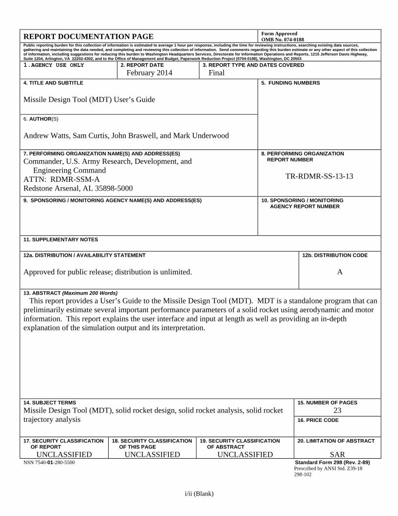
REPORT DOCUMENTATION PAGE Form Approved OMB No. 074-0188
Public reporting burden for this collection of information is estimated to average 1 hour per response, including the time for reviewing instructions, searching existing data sources, gathering and maintaining the data needed, and completing and reviewing this collection of information. Send comments regarding this burden estimate or any other aspect of this collection of information, including suggestions for reducing this burden to Washington Headquarters Services, Directorate for Information Operations and Reports, 1215 Jefferson Davis Highway, Suite 1204, Arlington, VA 22202-4302, and to the Office of Management and Budget, Paperwork Reduction Project (0704-0188), Washington, DC 20503
1.AGENCY USE ONLY
2. REPORT DATE
February 2014 3. REPORT TYPE AND DATES COVERED Final
4. TITLE AND SUBTITLE Missile Design Tool (MDT) User’s Guide
5. FUNDING NUMBERS
6. AUTHOR(S)
Andrew Watts, Sam Curtis, John Braswell, and Mark Underwood
7. PERFORMING ORGANIZATION NAME(S) AND ADDRESS(ES)
Commander, U.S. Army Research, Development, and Engineering Command ATTN: RDMR-SSM-A Redstone Arsenal, AL 35898-5000
8. PERFORMING ORGANIZATION REPORT NUMBER
TR-RDMR-SS-13-13
9. SPONSORING / MONITORING AGENCY NAME(S) AND ADDRESS(ES) 10. SPONSORING / MONITORING AGENCY REPORT NUMBER
11. SUPPLEMENTARY NOTES 12a. DISTRIBUTION / AVAILABILITY STATEMENT
Approved for public release; distribution is unlimited.
12b. DISTRIBUTION CODE
A
13. ABSTRACT (Maximum 200 Words) This report provides a User’s Guide to the Missile Design Tool (MDT). MDT is a standalone program that can preliminarily estimate several important performance parameters of a solid rocket using aerodynamic and motor information. This report explains the user interface and input at length as well as providing an in-depth explanation of the simulation output and its interpretation.
14. SUBJECT TERMS
Missile Design Tool (MDT), solid rocket design, solid rocket analysis, solid rocket trajectory analysis
15. NUMBER OF PAGES
23 16. PRICE CODE
17. SECURITY CLASSIFICATION OF REPORT
UNCLASSIFIED
18. SECURITY CLASSIFICATION OF THIS PAGE
UNCLASSIFIED
19. SECURITY CLASSIFICATION OF ABSTRACT
UNCLASSIFIED
20. LIMITATION OF ABSTRACT
SARNSN 7540-01-280-5500 Standard Form 298 (Rev. 2-89)
Prescribed by ANSI Std. Z39-18 298-102
iii
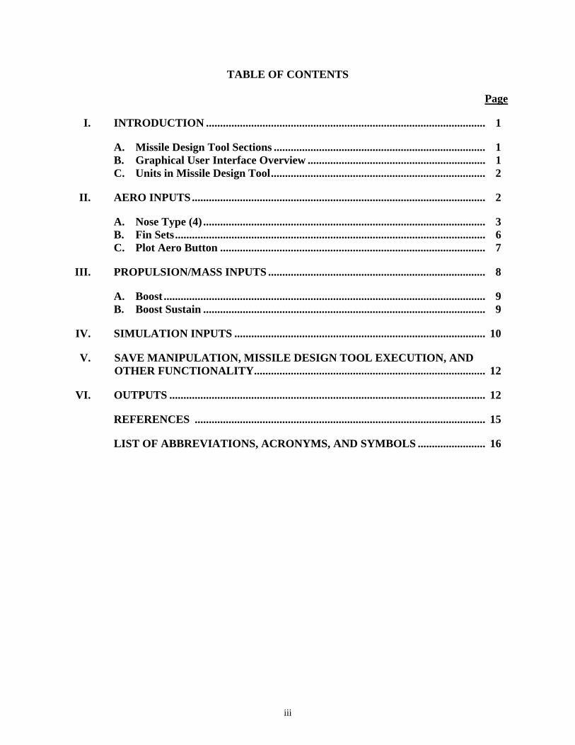
TABLE OF CONTENTS
Page
I. INTRODUCTION ................................................................................................... 1
A. Missile Design Tool Sections ........................................................................... 1 B. Graphical User Interface Overview ............................................................... 1 C. Units in Missile Design Tool ............................................................................ 2
II. AERO INPUTS ........................................................................................................ 2
A. Nose Type (4) .................................................................................................... 3 B. Fin Sets .............................................................................................................. 6 C. Plot Aero Button .............................................................................................. 7
III. PROPULSION/MASS INPUTS ............................................................................. 8
A. Boost .................................................................................................................. 9 B. Boost Sustain .................................................................................................... 9
IV. SIMULATION INPUTS ......................................................................................... 10
V. SAVE MANIPULATION, MISSILE DESIGN TOOL EXECUTION, AND OTHER FUNCTIONALITY .................................................................................. 12
VI. OUTPUTS ................................................................................................................ 12
REFERENCES ....................................................................................................... 15
LIST OF ABBREVIATIONS, ACRONYMS, AND SYMBOLS ........................ 16
iv
LIST OF ILLUSTRATIONS
Figure Title Page
1. MDT Input and Output Blocks .............................................................................. 2
2. Labeled Aero Input Vehicle Sketch ....................................................................... 3
3. Ogive Nose Upper Half ............................................................................................ 4
4. Cone Nose ................................................................................................................. 5
5. Power Law Nose Cone ............................................................................................. 6
6. Labeled Fin Vehicle Sketch .................................................................................... 6
7. Boost and Sustain Thrust Comparison .................................................................. 8
8. MDT Payload and Motor Length Comparison .................................................... 9
9. MDT Burn Timeline Example ................................................................................ 10
10. Flight Path Angle Convention ................................................................................ 11
11. Guidance Example Flight Path and Range Profile ............................................... 11
12. MDT Output Plots ................................................................................................... 14
LIST OF TABLES
Table Title Page
1. Summary of MDT Sections ..................................................................................... 1
2. Figure 2 Aero Inputs ............................................................................................... 3
3. Figure 6 Fin Set Values ........................................................................................... 6
4. Figure 11 Guidance Commands ............................................................................. 11
5. MDT Input for Varied Boost Test Case ................................................................ 13
6. Varied Boost Test Case Boost Parameters ............................................................ 13
1
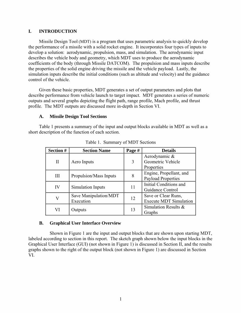
I. INTRODUCTION
Missile Design Tool (MDT) is a program that uses parametric analysis to quickly develop the performance of a missile with a solid rocket engine. It incorporates four types of inputs to develop a solution: aerodynamic, propulsion, mass, and simulation. The aerodynamic input describes the vehicle body and geometry, which MDT uses to produce the aerodynamic coefficients of the body (through Missile DATCOM). The propulsion and mass inputs describe the properties of the solid engine driving the missile and the vehicle payload. Lastly, the simulation inputs describe the initial conditions (such as altitude and velocity) and the guidance control of the vehicle.
Given these basic properties, MDT generates a set of output parameters and plots that describe performance from vehicle launch to target impact. MDT generates a series of numeric outputs and several graphs depicting the flight path, range profile, Mach profile, and thrust profile. The MDT outputs are discussed more in-depth in Section VI.
A. Missile Design Tool Sections
Table 1 presents a summary of the input and output blocks available in MDT as well as a short description of the function of each section.
Table 1. Summary of MDT Sections
Section # Section Name Page # Details
II Aero Inputs 3 Aerodynamic & Geometric Vehicle Properties
III Propulsion/Mass Inputs 8 Engine, Propellant, and Payload Properties
IV Simulation Inputs 11 Initial Conditions and Guidance Control
V Save Manipulation/MDT Execution
12 Save or Clear Runs, Execute MDT Simulation
VI Outputs 13 Simulation Results & Graphs
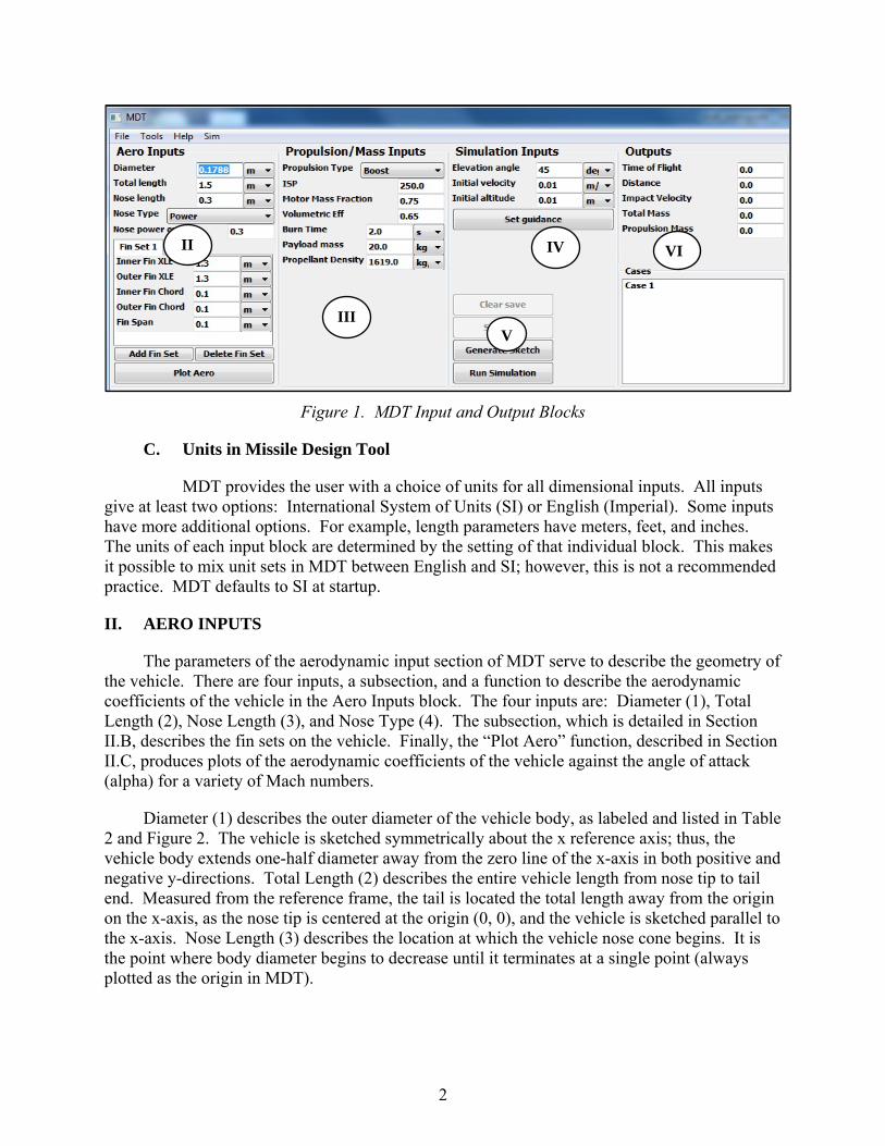
B. Graphical User Interface Overview
Shown in Figure 1 are the input and output blocks that are shown upon starting MDT, labeled according to section in this report. The sketch graph shown below the input blocks in the Graphical User Interface (GUI) (not shown in Figure 1) is discussed in Section II, and the results graphs shown to the right of the output block (not shown in Figure 1) are discussed in Section VI.
2
Figure 1. MDT Input and Output Blocks
C. Units in Missile Design Tool
MDT provides the user with a choice of units for all dimensional inputs. All inputs give at least two options: International System of Units (SI) or English (Imperial). Some inputs have more additional options. For example, length parameters have meters, feet, and inches. The units of each input block are determined by the setting of that individual block. This makes it possible to mix unit sets in MDT between English and SI; however, this is not a recommended practice. MDT defaults to SI at startup.
II. AERO INPUTS
The parameters of the aerodynamic input section of MDT serve to describe the geometry of the vehicle. There are four inputs, a subsection, and a function to describe the aerodynamic coefficients of the vehicle in the Aero Inputs block. The four inputs are: Diameter (1), Total Length (2), Nose Length (3), and Nose Type (4). The subsection, which is detailed in Section II.B, describes the fin sets on the vehicle. Finally, the “Plot Aero” function, described in Section II.C, produces plots of the aerodynamic coefficients of the vehicle against the angle of attack (alpha) for a variety of Mach numbers.
Diameter (1) describes the outer diameter of the vehicle body, as labeled and listed in Table 2 and Figure 2. The vehicle is sketched symmetrically about the x reference axis; thus, the vehicle body extends one-half diameter away from the zero line of the x-axis in both positive and negative y-directions. Total Length (2) describes the entire vehicle length from nose tip to tail end. Measured from the reference frame, the tail is located the total length away from the origin on the x-axis, as the nose tip is centered at the origin (0, 0), and the vehicle is sketched parallel to the x-axis. Nose Length (3) describes the location at which the vehicle nose cone begins. It is the point where body diameter begins to decrease until it terminates at a single point (always plotted as the origin in MDT).
V
IV II
III
VI
3
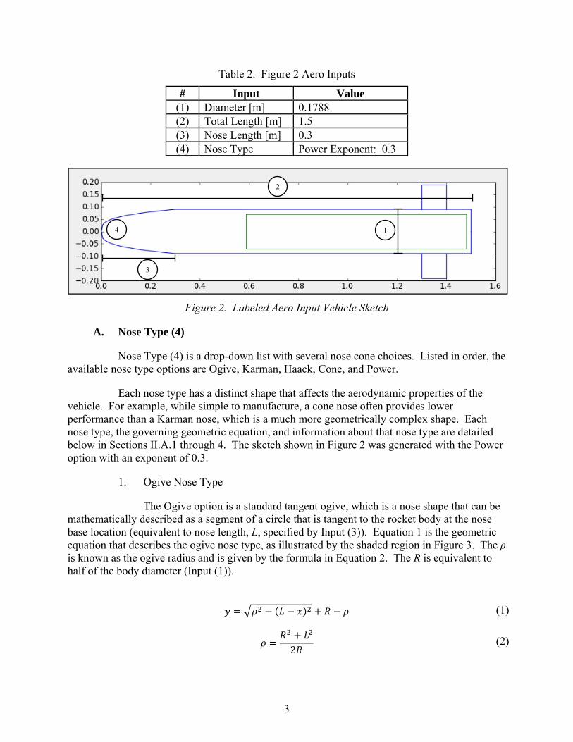
Table 2. Figure 2 Aero Inputs
# Input Value (1) Diameter [m] 0.1788 (2) Total Length [m] 1.5 (3) Nose Length [m] 0.3 (4) Nose Type Power Exponent: 0.3
Figure 2. Labeled Aero Input Vehicle Sketch
A. Nose Type (4)
Nose Type (4) is a drop-down list with several nose cone choices. Listed in order, the available nose type options are Ogive, Karman, Haack, Cone, and Power.
Each nose type has a distinct shape that affects the aerodynamic properties of the vehicle. For example, while simple to manufacture, a cone nose often provides lower performance than a Karman nose, which is a much more geometrically complex shape. Each nose type, the governing geometric equation, and information about that nose type are detailed below in Sections II.A.1 through 4. The sketch shown in Figure 2 was generated with the Power option with an exponent of 0.3.
1. Ogive Nose Type
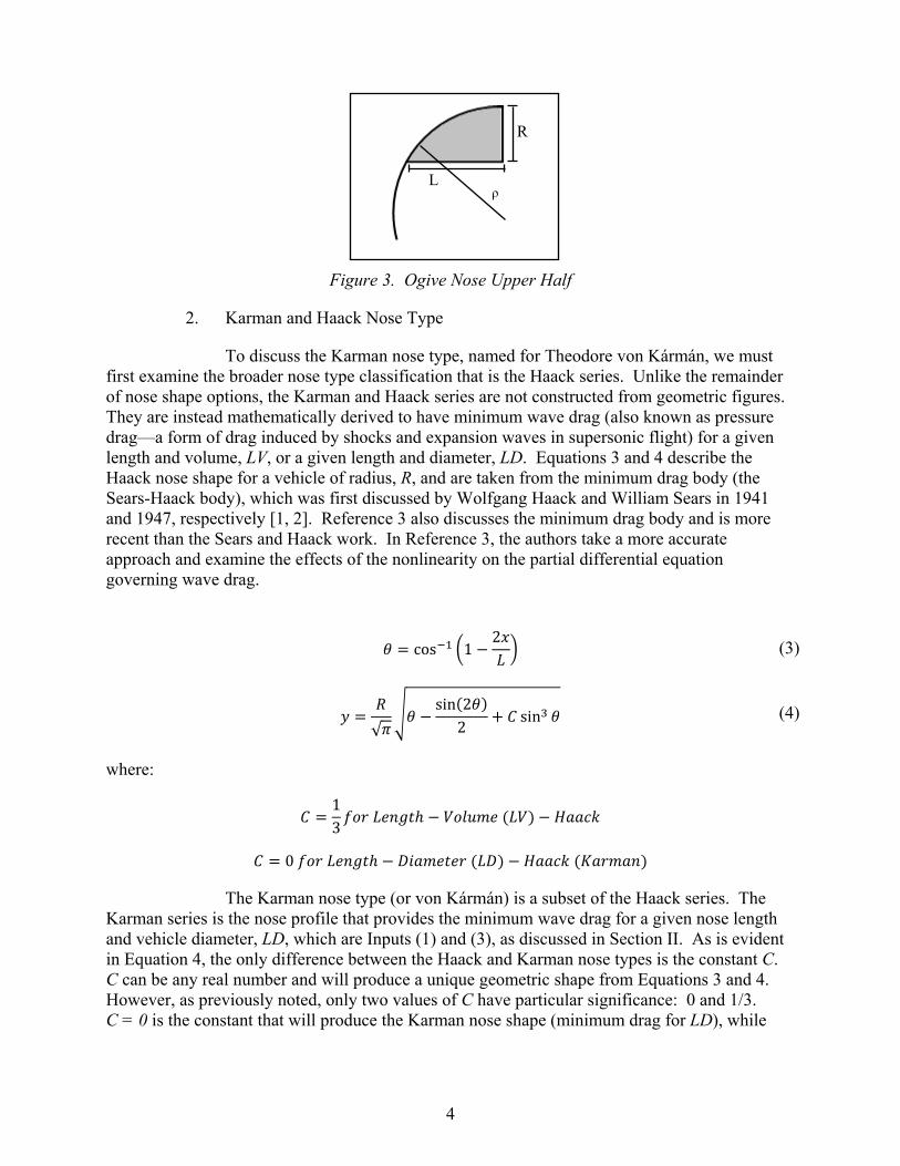
The Ogive option is a standard tangent ogive, which is a nose shape that can be mathematically described as a segment of a circle that is tangent to the rocket body at the nose base location (equivalent to nose length, L, specified by Input (3)). Equation 1 is the geometric equation that describes the ogive nose type, as illustrated by the shaded region in Figure 3. The ρ is known as the ogive radius and is given by the formula in Equation 2. The R is equivalent to half of the body diameter (Input (1)).
(1)
2
(2)
2
14
3
4
Figure 3. Ogive Nose Upper Half
2. Karman and Haack Nose Type
To discuss the Karman nose type, named for Theodore von Kármán, we must first examine the broader nose type classification that is the Haack series. Unlike the remainder of nose shape options, the Karman and Haack series are not constructed from geometric figures. They are instead mathematically derived to have minimum wave drag (also known as pressure drag—a form of drag induced by shocks and expansion waves in supersonic flight) for a given length and volume, LV, or a given length and diameter, LD. Equations 3 and 4 describe the Haack nose shape for a vehicle of radius, R, and are taken from the minimum drag body (the Sears-Haack body), which was first discussed by Wolfgang Haack and William Sears in 1941 and 1947, respectively [1, 2]. Reference 3 also discusses the minimum drag body and is more recent than the Sears and Haack work. In Reference 3, the authors take a more accurate approach and examine the effects of the nonlinearity on the partial differential equation governing wave drag.
where:
13
0
The Karman nose type (or von Kármán) is a subset of the Haack series. The Karman series is the nose profile that provides the minimum wave drag for a given nose length and vehicle diameter, LD, which are Inputs (1) and (3), as discussed in Section II. As is evident in Equation 4, the only difference between the Haack and Karman nose types is the constant C. C can be any real number and will produce a unique geometric shape from Equations 3 and 4. However, as previously noted, only two values of C have particular significance: 0 and 1/3. C = 0 is the constant that will produce the Karman nose shape (minimum drag for LD), while
cos 12
(3)
√
sin 22
sin (4)
R
Lρ
5
C = 1/3 will produce the nose shape that has the minimum drag for a desired nose cone length and volume, LV.
3. Cone Nose Type
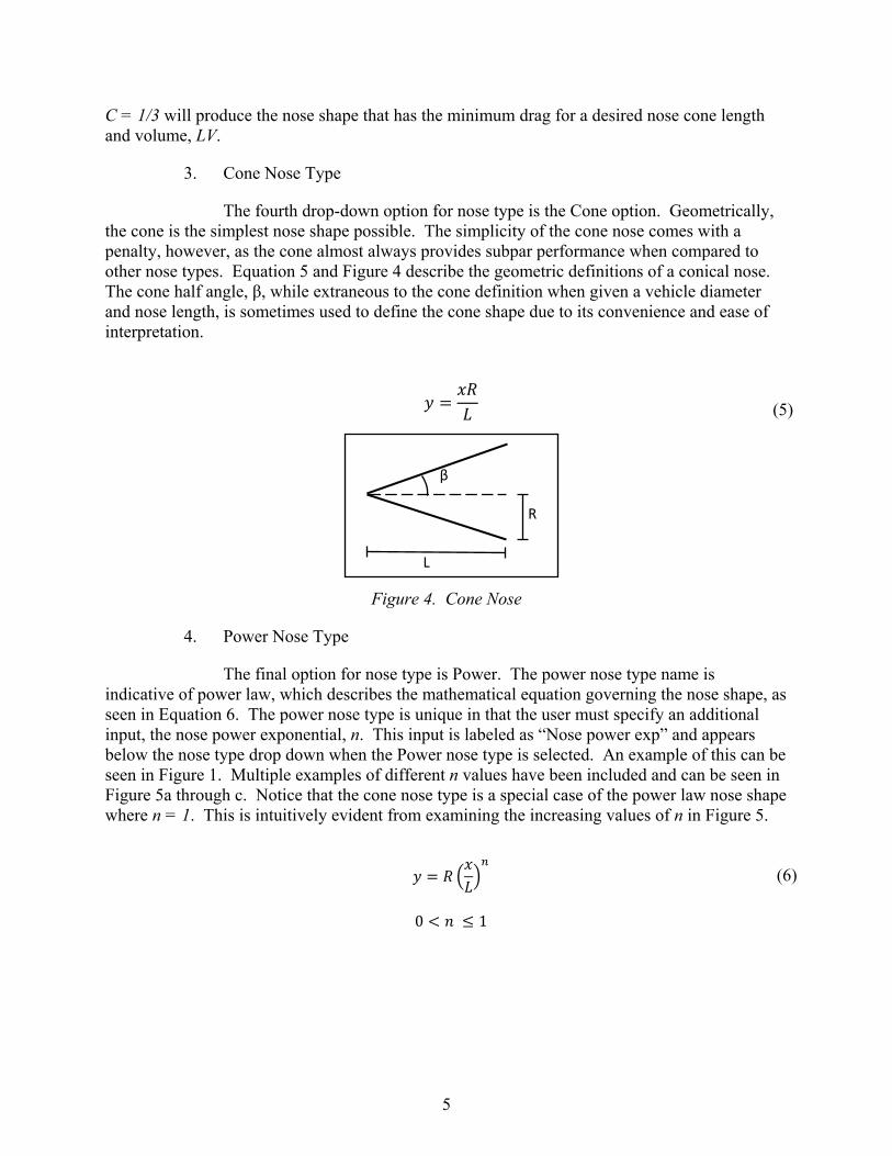
The fourth drop-down option for nose type is the Cone option. Geometrically, the cone is the simplest nose shape possible. The simplicity of the cone nose comes with a penalty, however, as the cone almost always provides subpar performance when compared to other nose types. Equation 5 and Figure 4 describe the geometric definitions of a conical nose. The cone half angle, β, while extraneous to the cone definition when given a vehicle diameter and nose length, is sometimes used to define the cone shape due to its convenience and ease of interpretation.
Figure 4. Cone Nose
4. Power Nose Type
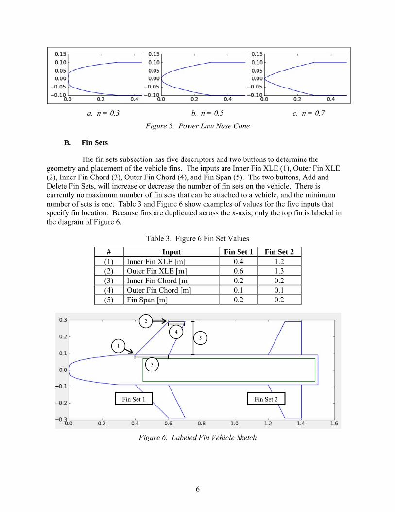
The final option for nose type is Power. The power nose type name is indicative of power law, which describes the mathematical equation governing the nose shape, as seen in Equation 6. The power nose type is unique in that the user must specify an additional input, the nose power exponential, n. This input is labeled as “Nose power exp” and appears below the nose type drop down when the Power nose type is selected. An example of this can be seen in Figure 1. Multiple examples of different n values have been included and can be seen in Figure 5a through c. Notice that the cone nose type is a special case of the power law nose shape where n = 1. This is intuitively evident from examining the increasing values of n in Figure 5.
(5)
(6)
0 1
β
L
R
6
a. n = 0.3 b. n = 0.5 c. n = 0.7
Figure 5. Power Law Nose Cone
B. Fin Sets
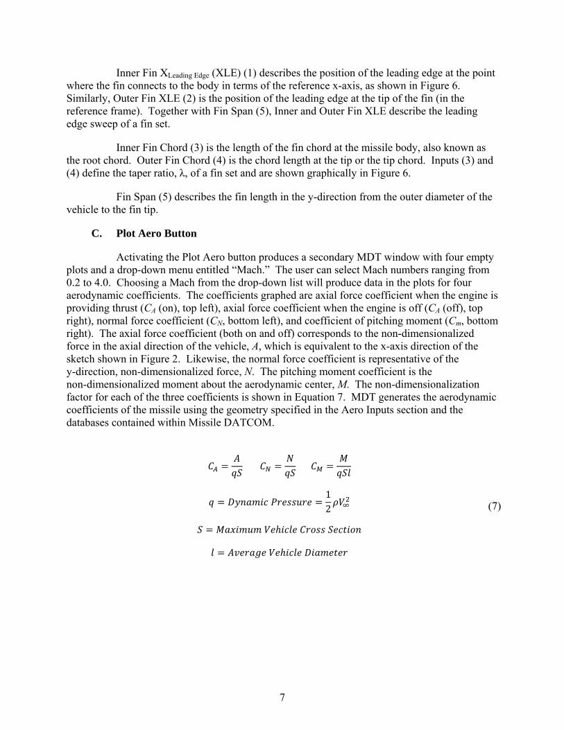
The fin sets subsection has five descriptors and two buttons to determine the geometry and placement of the vehicle fins. The inputs are Inner Fin XLE (1), Outer Fin XLE (2), Inner Fin Chord (3), Outer Fin Chord (4), and Fin Span (5). The two buttons, Add and Delete Fin Sets, will increase or decrease the number of fin sets on the vehicle. There is currently no maximum number of fin sets that can be attached to a vehicle, and the minimum number of sets is one. Table 3 and Figure 6 show examples of values for the five inputs that specify fin location. Because fins are duplicated across the x-axis, only the top fin is labeled in the diagram of Figure 6.
Table 3. Figure 6 Fin Set Values
# Input Fin Set 1 Fin Set 2 (1) Inner Fin XLE [m] 0.4 1.2 (2) Outer Fin XLE [m] 0.6 1.3 (3) Inner Fin Chord [m] 0.2 0.2 (4) Outer Fin Chord [m] 0.1 0.1 (5) Fin Span [m] 0.2 0.2
Figure 6. Labeled Fin Vehicle Sketch
2
1
3
45
Fin Set 1 Fin Set 2
7
Inner Fin XLeading Edge (XLE) (1) describes the position of the leading edge at the point where the fin connects to the body in terms of the reference x-axis, as shown in Figure 6. Similarly, Outer Fin XLE (2) is the position of the leading edge at the tip of the fin (in the reference frame). Together with Fin Span (5), Inner and Outer Fin XLE describe the leading edge sweep of a fin set.
Inner Fin Chord (3) is the length of the fin chord at the missile body, also known as the root chord. Outer Fin Chord (4) is the chord length at the tip or the tip chord. Inputs (3) and (4) define the taper ratio, λ, of a fin set and are shown graphically in Figure 6.
Fin Span (5) describes the fin length in the y-direction from the outer diameter of the vehicle to the fin tip.
C. Plot Aero Button
Activating the Plot Aero button produces a secondary MDT window with four empty plots and a drop-down menu entitled “Mach.” The user can select Mach numbers ranging from 0.2 to 4.0. Choosing a Mach from the drop-down list will produce data in the plots for four aerodynamic coefficients. The coefficients graphed are axial force coefficient when the engine is providing thrust (CA (on), top left), axial force coefficient when the engine is off (CA (off), top right), normal force coefficient (CN, bottom left), and coefficient of pitching moment (Cm, bottom right). The axial force coefficient (both on and off) corresponds to the non-dimensionalized force in the axial direction of the vehicle, A, which is equivalent to the x-axis direction of the sketch shown in Figure 2. Likewise, the normal force coefficient is representative of the y-direction, non-dimensionalized force, N. The pitching moment coefficient is the non-dimensionalized moment about the aerodynamic center, M. The non-dimensionalization factor for each of the three coefficients is shown in Equation 7. MDT generates the aerodynamic coefficients of the missile using the geometry specified in the Aero Inputs section and the databases contained within Missile DATCOM.
(7)
12
8
III. PROPULSION/MASS INPUT
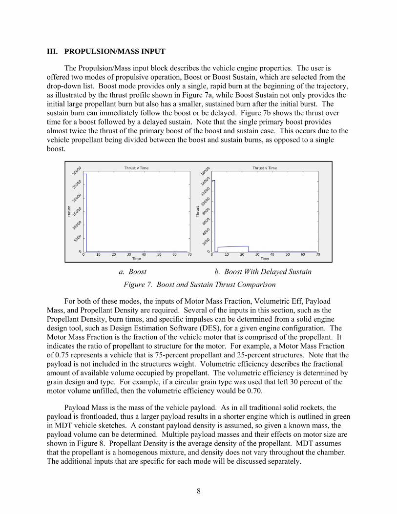
The Propulsion/Mass input block describes the vehicle engine properties. The user is offered two modes of propulsive operation, Boost or Boost Sustain, which are selected from the drop-down list. Boost mode provides only a single, rapid burn at the beginning of the trajectory, as illustrated by the thrust profile shown in Figure 7a, while Boost Sustain not only provides the initial large propellant burn but also has a smaller, sustained burn after the initial burst. The sustain burn can immediately follow the boost or be delayed. Figure 7b shows the thrust over time for a boost followed by a delayed sustain. Note that the single primary boost provides almost twice the thrust of the primary boost of the boost and sustain case. This occurs due to the vehicle propellant being divided between the boost and sustain burns, as opposed to a single boost.
a. Boost b. Boost With Delayed Sustain
Figure 7. Boost and Sustain Thrust Comparison
For both of these modes, the inputs of Motor Mass Fraction, Volumetric Eff, Payload Mass, and Propellant Density are required. Several of the inputs in this section, such as the Propellant Density, burn times, and specific impulses can be determined from a solid engine design tool, such as Design Estimation Software (DES), for a given engine configuration. The Motor Mass Fraction is the fraction of the vehicle motor that is comprised of the propellant. It indicates the ratio of propellant to structure for the motor. For example, a Motor Mass Fraction of 0.75 represents a vehicle that is 75-percent propellant and 25-percent structures. Note that the payload is not included in the structures weight. Volumetric efficiency describes the fractional amount of available volume occupied by propellant. The volumetric efficiency is determined by grain design and type. For example, if a circular grain type was used that left 30 percent of the motor volume unfilled, then the volumetric efficiency would be 0.70.
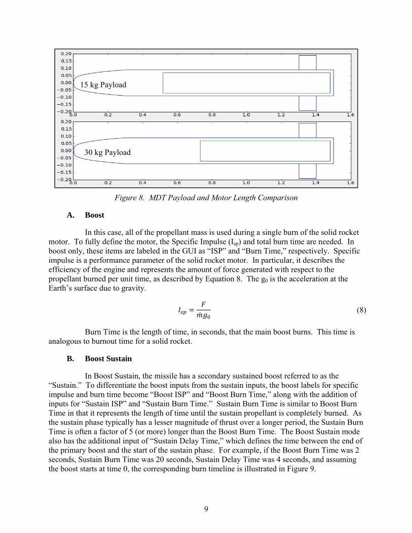
Payload Mass is the mass of the vehicle payload. As in all traditional solid rockets, the payload is frontloaded, thus a larger payload results in a shorter engine which is outlined in green in MDT vehicle sketches. A constant payload density is assumed, so given a known mass, the payload volume can be determined. Multiple payload masses and their effects on motor size are shown in Figure 8. Propellant Density is the average density of the propellant. MDT assumes that the propellant is a homogenous mixture, and density does not vary throughout the chamber. The additional inputs that are specific for each mode will be discussed separately.
9
Figure 8. MDT Payload and Motor Length Comparison
A. Boost
In this case, all of the propellant mass is used during a single burn of the solid rocket motor. To fully define the motor, the Specific Impulse (Isp) and total burn time are needed. In boost only, these items are labeled in the GUI as “ISP” and “Burn Time,” respectively. Specific impulse is a performance parameter of the solid rocket motor. In particular, it describes the efficiency of the engine and represents the amount of force generated with respect to the propellant burned per unit time, as described by Equation 8. The g0 is the acceleration at the Earth’s surface due to gravity.
Burn Time is the length of time, in seconds, that the main boost burns. This time is analogous to burnout time for a solid rocket.
B. Boost Sustain
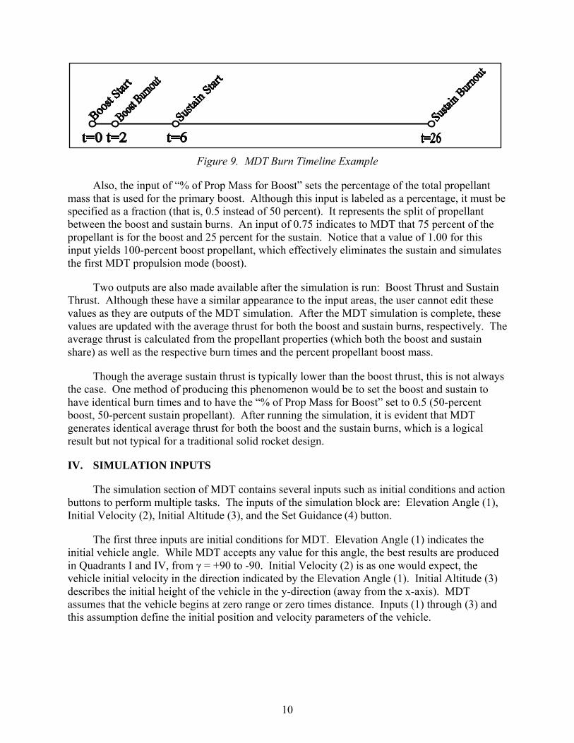
In Boost Sustain, the missile has a secondary sustained boost referred to as the “Sustain.” To differentiate the boost inputs from the sustain inputs, the boost labels for specific impulse and burn time become “Boost ISP” and “Boost Burn Time,” along with the addition of inputs for “Sustain ISP” and “Sustain Burn Time.” Sustain Burn Time is similar to Boost Burn Time in that it represents the length of time until the sustain propellant is completely burned. As the sustain phase typically has a lesser magnitude of thrust over a longer period, the Sustain Burn Time is often a factor of 5 (or more) longer than the Boost Burn Time. The Boost Sustain mode also has the additional input of “Sustain Delay Time,” which defines the time between the end of the primary boost and the start of the sustain phase. For example, if the Boost Burn Time was 2 seconds, Sustain Burn Time was 20 seconds, Sustain Delay Time was 4 seconds, and assuming the boost starts at time 0, the corresponding burn timeline is illustrated in Figure 9.
(8)
15 kg Payload
30 kg Payload
10
Figure 9. MDT Burn Timeline Example
Also, the input of “% of Prop Mass for Boost” sets the percentage of the total propellant mass that is used for the primary boost. Although this input is labeled as a percentage, it must be specified as a fraction (that is, 0.5 instead of 50 percent). It represents the split of propellant between the boost and sustain burns. An input of 0.75 indicates to MDT that 75 percent of the propellant is for the boost and 25 percent for the sustain. Notice that a value of 1.00 for this input yields 100-percent boost propellant, which effectively eliminates the sustain and simulates the first MDT propulsion mode (boost).
Two outputs are also made available after the simulation is run: Boost Thrust and Sustain Thrust. Although these have a similar appearance to the input areas, the user cannot edit these values as they are outputs of the MDT simulation. After the MDT simulation is complete, these values are updated with the average thrust for both the boost and sustain burns, respectively. The average thrust is calculated from the propellant properties (which both the boost and sustain share) as well as the respective burn times and the percent propellant boost mass.
Though the average sustain thrust is typically lower than the boost thrust, this is not always the case. One method of producing this phenomenon would be to set the boost and sustain to have identical burn times and to have the “% of Prop Mass for Boost” set to 0.5 (50-percent boost, 50-percent sustain propellant). After running the simulation, it is evident that MDT generates identical average thrust for both the boost and the sustain burns, which is a logical result but not typical for a traditional solid rocket design.
IV. SIMULATION INPUTS
The simulation section of MDT contains several inputs such as initial conditions and action buttons to perform multiple tasks. The inputs of the simulation block are: Elevation Angle (1), Initial Velocity (2), Initial Altitude (3), and the Set Guidance (4) button.
The first three inputs are initial conditions for MDT. Elevation Angle (1) indicates the initial vehicle angle. While MDT accepts any value for this angle, the best results are produced in Quadrants I and IV, from γ = +90 to -90. Initial Velocity (2) is as one would expect, the vehicle initial velocity in the direction indicated by the Elevation Angle (1). Initial Altitude (3) describes the initial height of the vehicle in the y-direction (away from the x-axis). MDT assumes that the vehicle begins at zero range or zero times distance. Inputs (1) through (3) and this assumption define the initial position and velocity parameters of the vehicle.
11
The Set Guidance (4) button opens a secondary MDT window which allows the user to give guidance instructions that the vehicle will execute during the simulation. GUI manipulation in the Set Guidance window is simple—each command has a time of execution and a command option. The Add button will add a new command to the end of the guidance list, whereas the Delete button removes the last command on the guidance list. Commands do not need to be chronologically sequential, but the vehicle will always attempt to satisfy the last command given.
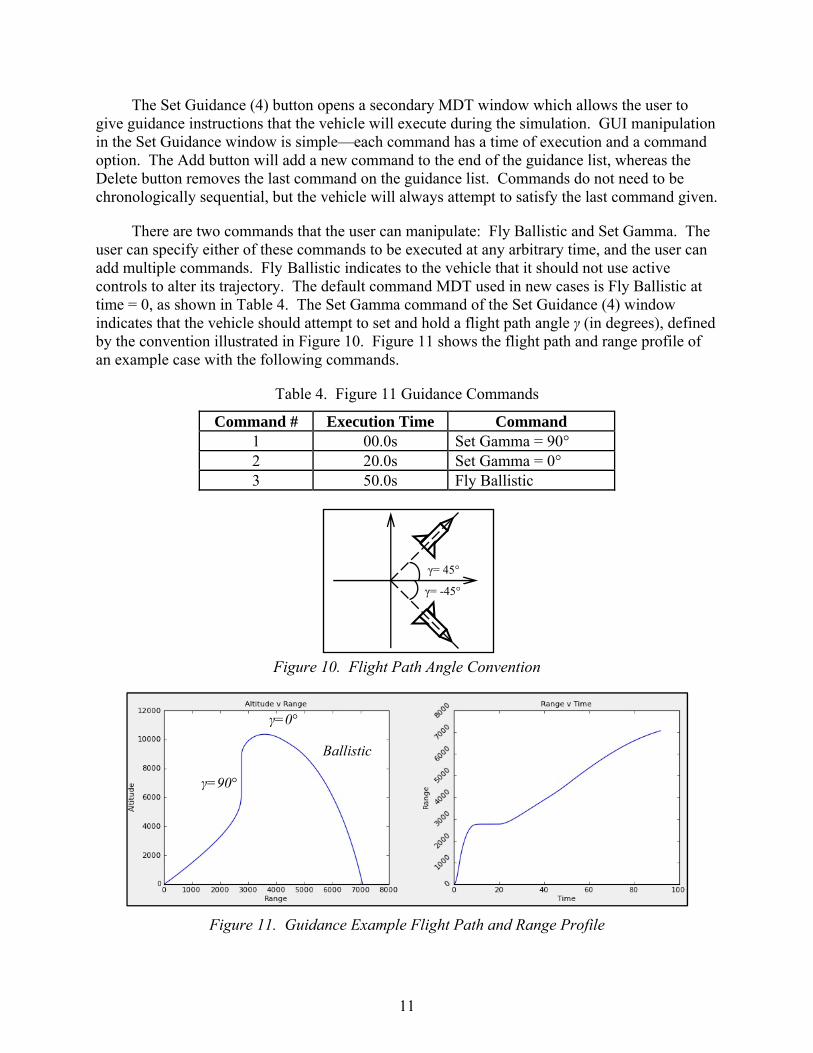
There are two commands that the user can manipulate: Fly Ballistic and Set Gamma. The user can specify either of these commands to be executed at any arbitrary time, and the user can add multiple commands. Fly Ballistic indicates to the vehicle that it should not use active controls to alter its trajectory. The default command MDT used in new cases is Fly Ballistic at time = 0, as shown in Table 4. The Set Gamma command of the Set Guidance (4) window indicates that the vehicle should attempt to set and hold a flight path angle γ (in degrees), defined by the convention illustrated in Figure 10. Figure 11 shows the flight path and range profile of an example case with the following commands.
Table 4. Figure 11 Guidance Commands
Command # Execution Time Command 1 00.0s Set Gamma = 90° 2 20.0s Set Gamma = 0° 3 50.0s Fly Ballistic
Figure 10. Flight Path Angle Convention
Figure 11. Guidance Example Flight Path and Range Profile
γ=90°
γ=0°
Ballistic
γ= 45°
γ= -45°
12
V. SAVE MANIPULATION, MISSILE DESIGN TOOL EXECUTION, AND OTHER FUNCTIONALITY
Below the Simulation Inputs block are four buttons that allow the user to manipulate MDT: Clear Save (1), Save Run (2), Generate Sketch (3), and Run Simulation (4).
The Clear Save (1) button removes all saves and deletes all cases in the GUI from the MDT history, which is listed to the right of the simulation inputs block and below the Outputs section, as seen in Figure 1. Save Run (2) saves the current settings on the current case in the History block and generates a new case. Each case in the MDT history is plotted on the output graphs, allowing the user to easily compare test cases.
The Generate Sketch (3) button uses the current geometric information in the Aero Inputs block, as discussed in Section II, to generate a Two-Dimensional (2-D) sketch of the vehicle. The sketch includes fin sets, engine/payload size, and nose cone. Run Simulation (4) runs the MDT simulation using all the current settings and generates the outputs and result graphs that are discussed in Section VI.
MDT also contains four drop-down menus that provide additional functionality. These menus are: File, Tools, Help, and Sim. The File drop-down menu contains three options: Save Configuration, Load Configuration, and Exit. The Save and Load Configurations will save or load a MDT case to or from a file, respectively. The file type MDT creates and uses is “.mdc” file. It is important to note that MDT will save or load only the active case, thus a Save Files needs to be created for each case that needs to be stored. The Exit button stops all operations and closes MDT.
The Tools drop-down menu allows one to export an input file for the Area Protection Tool (APT) by selecting the only available option, “Create APT Input.” This option creates a “.fly” file which contains time-discrete, space-delimited vehicle information. Time steps are given in 0.05 seconds, and the information included is the vehicle velocity, range, altitude, and flight path angle. The Help drop-down menu also contains a single option: About. Activating the “About” button from the help drop-down menu will provide information about MDT, such as the version number, current available functionalities, and primary authors.
Sim, the final drop-down menu, uses Google Earth (GE), which is labeled in the GUI as GE Flyout. This functionality requires the user to have a licensed copy of the desktop program “Google Earth Pro” installed. Once activated, the “GE Flyout” button will open Google Earth and generate the vehicle flight determined by MDT overlaid on the Google Earth map.
VI. OUTPUTS
The Outputs section of MDT contains no user controlled inputs but instead contains five output blocks that are populated after the MDT simulation has been successfully completed with a set of valid inputs gathered from the first three sections. The output blocks are: Time of Flight (1), Distance (2), Impact Velocity (3), Total Mass (4), and Propulsion Mass (5).
13
Time of Flight (1) is the total time, in seconds, from time zero until the vehicle reaches (or returns to) zero altitude. Distance (2) is the range of the vehicle in meters, the total distance traveled in the x direction. Impact Velocity (3) is the magnitude of the vehicle’s velocity in meters per second upon impact at the Time of Flight (1) and Distance (2). Total Mass (4) is the entire mass (in kilograms) of the vehicle including payload, propulsion, and motor structure. Propulsion Mass (5) is the isolated propulsion mass in kilograms. Propulsion Mass (5) does not include vehicle or engine structures. Using Outputs (4), (5), and the user-input Payload Mass from Section III, the mass of the vehicle support structure can be determined, which corresponds to the Motor Mass Fraction input of the same section.
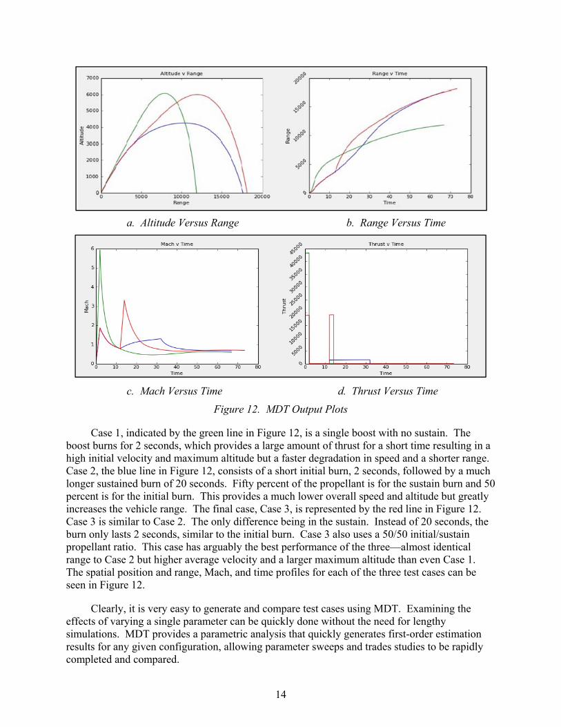
MDT produces four output graphs along with its five outputs: Altitude Versus Range (1), Range Versus Time (2), Mach Versus Time (3), and Thrust Versus Time (4). Altitude and Range are each in meters, time is in seconds, and thrust is in newtons. In general, graph (1) can be thought of as a grid that specifies x-y position at any given point in time, and graphs (2) through (4) each indicate a profile over time: distance, velocity, and thrust, respectively.
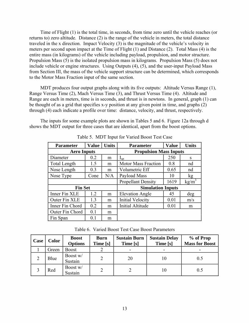
The inputs for some example plots are shown in Tables 5 and 6. Figure 12a through d shows the MDT output for three cases that are identical, apart from the boost options.
Table 5. MDT Input for Varied Boost Test Case
Parameter Value Units Parameter Value Units Aero Inputs Propulsion Mass Inputs
Diameter 0.2 m Isp 250 s Total Length 1.5 m Motor Mass Fraction 0.8 nd Nose Length 0.3 m Volumetric Eff 0.65 nd Nose Type Cone N/A Payload Mass 10 kg Propellant Density 1619 kg/m3
Fin Set Simulation Inputs Inner Fin XLE 1.2 m Elevation Angle 45 deg Outer Fin XLE 1.3 m Initial Velocity 0.01 m/s Inner Fin Chord 0.2 m Initial Altitude 0.01 m Outer Fin Chord 0.1 m Fin Span 0.1 m
Table 6. Varied Boost Test Case Boost Parameters
Case Color Boost
Options Burn
Time [s] Sustain Burn
Time [s] Sustain Delay
Time [s] % of Prop
Mass for Boost 1 Green Boost 2 - - -
2 Blue Boost w/ Sustain
2 20 10 0.5
3 Red Boost w/ Sustain
2 2 10 0.5
14
a. Altitude Versus Range b. Range Versus Time
c. Mach Versus Time d. Thrust Versus Time
Figure 12. MDT Output Plots
Case 1, indicated by the green line in Figure 12, is a single boost with no sustain. The boost burns for 2 seconds, which provides a large amount of thrust for a short time resulting in a high initial velocity and maximum altitude but a faster degradation in speed and a shorter range. Case 2, the blue line in Figure 12, consists of a short initial burn, 2 seconds, followed by a much longer sustained burn of 20 seconds. Fifty percent of the propellant is for the sustain burn and 50 percent is for the initial burn. This provides a much lower overall speed and altitude but greatly increases the vehicle range. The final case, Case 3, is represented by the red line in Figure 12. Case 3 is similar to Case 2. The only difference being in the sustain. Instead of 20 seconds, the burn only lasts 2 seconds, similar to the initial burn. Case 3 also uses a 50/50 initial/sustain propellant ratio. This case has arguably the best performance of the three—almost identical range to Case 2 but higher average velocity and a larger maximum altitude than even Case 1. The spatial position and range, Mach, and time profiles for each of the three test cases can be seen in Figure 12.
Clearly, it is very easy to generate and compare test cases using MDT. Examining the effects of varying a single parameter can be quickly done without the need for lengthy simulations. MDT provides a parametric analysis that quickly generates first-order estimation results for any given configuration, allowing parameter sweeps and trades studies to be rapidly completed and compared.
15
REFERENCES
1. Haack, Wolfgang, Geschossformen kleinsten Wellenwiderstandes (Shapes of Smallest Wave Resistance), Lilienthal-Gesellschaft fur Luftfahrtforschung (Lilienthal Society for Aeronautical Research), Volume Report 139, Number Part 1, 1941.
2. Sears, William R., On Projectiles of Minimum Wave Drag, Volume IV, Number 4, 1947.
3. Palaniappan, Karthik and Jameson, Antony, “Bodies having Minimum Pressure Drag in Supersonic Flow - Investigating Nonlinear Effects,” 22nd Applied Aerodynamics Conference and Exhibit, Providence, RI, August 2004.
16
LIST OF ABBREVIATIONS, ACRONYMS, AND SYMBOLS
# number
% percent
= equals
° degree
2-D Two-Dimensional
Aero Aerodynamics
APT Area Protection Tool
deg degree
DES Design Estimation Software
Eff Efficiency
exp Exponential
GE Google Earth
GUI Graphical User Interface
ISP Specific Impulse
kg kilogram
m meter
m3 cubic meter
MDT Missile Design Tool
m/s meter/second
nd Non-Dimensional
Prop Propellant
s second
SI International System of Units
SIM Simulation
v versus
w/ with
XLE XLeading Edge
Dist-1
INITIAL DISTRIBUTION LIST
Copies Weapon Systems Technology Ms. Gina Nash Electronic Information Analysis Center [email protected] Alion Science and Technology 201 Mill Street Rome, NY 13440
Defense Technical Information Center Mr. Jack L. Rike Electronic 8725 John J. Kingman Rd., Suite 0944 [email protected] Fort Belvoir, VA 22060-6218
AMSAM-L Ms. Anne C. Lanteigne Electronic [email protected] Mr. Michael K. Gray Electronic [email protected]
RDMR Electronic
RDMR-CSI Electronic
RDMR-SSM Mr. Lamar Auman Electronic/Hardcopy [email protected]
RDMR-SSM-A Mr. John D. Braswell Electronic john.d.braswell.civ@mail,mil Mr. Mark Underwood Electronic [email protected] Mr. Andrew Watts Electronic [email protected] Mr. Brett Wilks Electronic [email protected]
RDMR-SSM-G Ms. Stephanie B. Reitmeier Electronic [email protected]
RDMR-SSL-T Mr. James S. Curtis Electronic [email protected]
RDMR-WD Mr. Michael S. Richman Electronic [email protected]
RDMR-WDG-C Ms. Susan Dunbar Electronic [email protected]
RDMR-WDP-E Mr. Nathan Mathis Electronic [email protected]

Dist-2
INITIAL DISTRIBUTION LIST (CONCLUDED)
Copies RDMR-WDP-P Mr. Scott Michaels Electronic
RDMR-WP-M Mr. Ronald G. Schmalbach Electronic [email protected]
Related Documents