SUBCOURSE EDITION OD1644 8 MILLING MACHINE OPERATIONS

Welcome message from author
This document is posted to help you gain knowledge. Please leave a comment to let me know what you think about it! Share it to your friends and learn new things together.
Transcript
SUBCOURSE EDITIONOD1644 8
MILLING MACHINE OPERATIONS

US ARMY WARRANT OFFICER ADVANCED COURSE
MOS/SKILL LEVEL: 441A
MILLING MACHINE OPERATIONS
SUBCOURSE NO. OD1644
EDITION 8
US Army CorrespondenceCourse Program
6 Credit Hours
NEW: 1988
GENERAL
The purpose of this subcourse is to introduce the student to the setup, operations and adjustments of the milling machine, which includes a discussion of the types of cutters used to perform various types of milling operations.
Six credit hours are awarded for successful completion of this subcourse.
Lesson 1: MILLING MACHINE OPERATIONS
TASK 1: Describe the setup, operation, and adjustment of the milling machine.
TASK 2: Describe the types, nomenclature, and use of milling cutters.
i
MILLING MACHINE OPERATIONS - OD1644
TABLE OF CONTENTS
Section Page
TITLE................................................................. i
TABLE OF CONTENTS..................................................... ii
Lesson 1: MILLING MACHINE OPERATIONS............................... 1
Task 1: Describe the setup, operation,and adjustment of the milling machine............................ 1
Task 2: Describe the types, nomenclature,and use of milling cutters....................................... 55
Practical Exercise 1............................................. 70
Answers to Practical Exercise 1.................................. 72
REFERENCES............................................................ 74
ii

MILLING MACHINE OPERATIONS - OD1644When used in this publication "he," "him," "his," and "men" represent both the masculine and feminine genders, unless otherwise stated.
iii

MILLING MACHINE OPERATIONS - OD1644
STUDENT NOTES
iv
MILLING MACHINE OPERATIONS - OD1644 - LESSON 1/TASK 1
LESSON 1
MILLING MACHINE OPERATIONS
TASK 1. Describe the setup, operation, and adjustment of the milling machine.
CONDITIONS
Within a self-study environment and given the subcourse text, without assistance.
STANDARDS
Within three hours
REFERENCES
No supplementary references are needed for this task.
1. Introduction
Milling machines were first invented and developed by Eli Whitney to mass produce interchangeable musket parts. Although crude, these machines assisted man in maintaining accuracy and uniformity while duplicating parts that could not be manufactured with the use of a file.
Development and improvements of the milling machine and components continued, which resulted in the manufacturing of heavier arbors and high speed steel and carbide cutters. These components allowed the operator to remove metal faster, and with more accuracy, than previous machines. Variations of milling machines were also developed to perform special milling operations. During this era, computerized machines have been developed to alleviate errors and provide better quality in the finished product.
1
MILLING MACHINE OPERATIONS - OD1644 - LESSON 1/TASK 1
2. Milling Machines
a. General. The milling machine removes metal with a revolving cutting tool called a milling cutter. With various attachments, milling machines can be used for boring, slotting, circular milling dividing, and drilling. This machine can also be used for cutting keyways, racks and gears and for fluting taps and reamers.
b. Types. Milling machines are basically classified as being horizontal or vertical to indicate the axis of the milling machine spindle. These machines are also classified as knee-type, ram-type, manufacturing or bed-type, and planer-type milling machines. Most machines have self-contained electric drive motors, coolant systems, variable spindle speeds, and power-operated table feeds.
(1) Knee-type Milling Machines. Knee-type milling machines are characterized by a vertical adjustable worktable resting on a saddle supported by a knee. The knee is a massive casting that rides vertically on the milling machine column and can be clamped rigidly to the column in a position where the milling head and the milling machine spindle are properly adjusted vertically for operation.
(a) Floor-mounted Plain Horizontal Milling Machine (figure 1 on the following page).
1 The floor-mounted plain horizontal milling machine's column contains the drive motor and, gearing and a fixed-position horizontal milling machine spindle. An adjustable overhead arm, containing one or more arbor supports, projects forward from the top of the column. The arm and arbor supports are used to stabilize long arbors, upon which the milling cutters are fixed. The arbor supports can be moved along the overhead arm to support the arbor wherever support is desired. This support will depend on the location of the milling cutter or cutters on the arbor.
2 The knee of the machine rides up or down the column on a rigid track. A heavy, vertical positioned screw beneath the knee is used for raising and lowering. The saddle rests upon the knee and supports the worktable. The saddle moves in and out on a dovetail to control the crossfeed
2
MILLING MACHINE OPERATIONS - OD1644 - LESSON 1/TASK 1
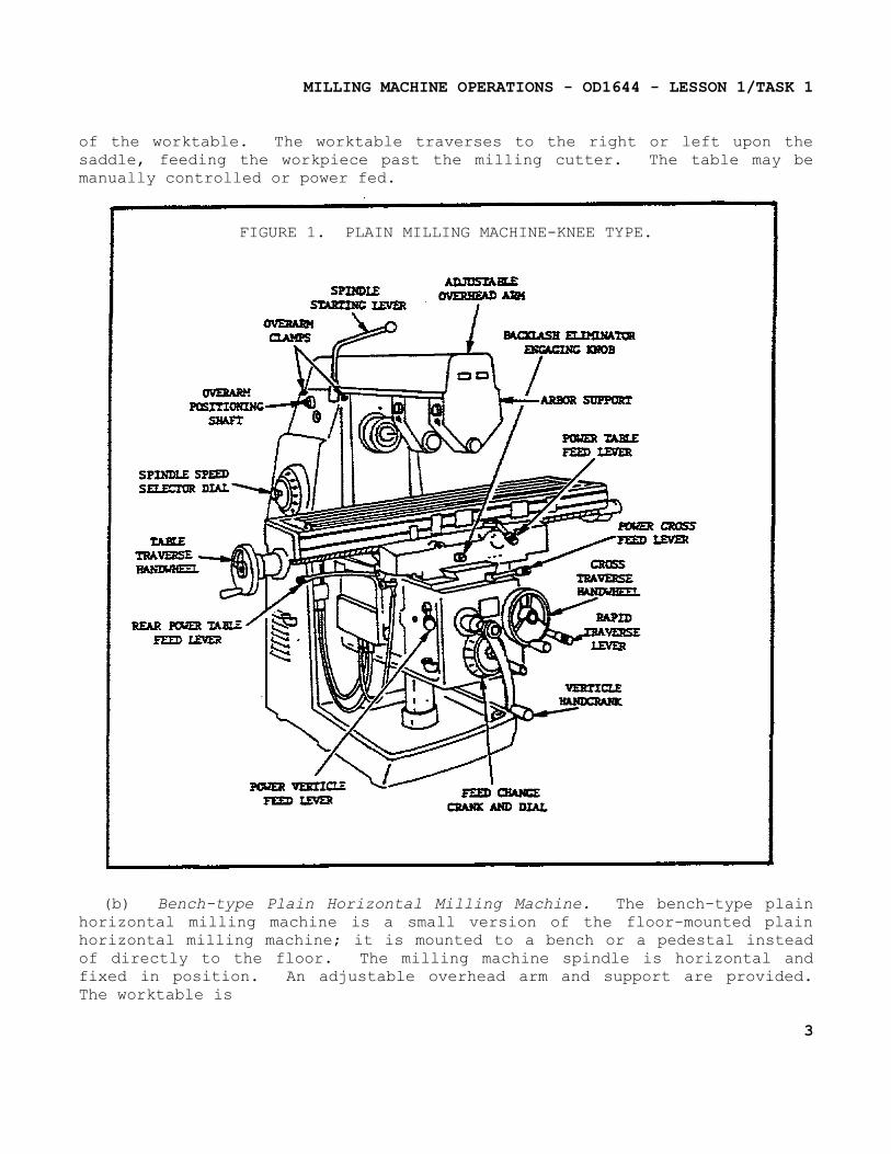
of the worktable. The worktable traverses to the right or left upon the saddle, feeding the workpiece past the milling cutter. The table may be manually controlled or power fed.
FIGURE 1. PLAIN MILLING MACHINE-KNEE TYPE.
(b) Bench-type Plain Horizontal Milling Machine. The bench-type plain horizontal milling machine is a small version of the floor-mounted plain horizontal milling machine; it is mounted to a bench or a pedestal instead of directly to the floor. The milling machine spindle is horizontal and fixed in position. An adjustable overhead arm and support are provided. The worktable is
3
MILLING MACHINE OPERATIONS - OD1644 - LESSON 1/TASK 1
generally not power fed on this size machine. The saddle slides on a dovetail on the knee providing crossfeed adjustment. The knee moves vertically up or down the column to position the worktable in relation to the spindle.
(c) Floor-mounted Universal Horizontal Milling Machine.
1 The basic difference between a universal horizontal milling machine and a plain horizontal milling machine is in the adjustment of the worktable, and in the number of attachments and accessories available for performing various special milling operations. The universal horizontal milling machine has a worktable that can swivel on the saddle with respect to the axis of the milling machine spindle, permitting workpieces to be adjusted in relation to the milling cutter.
2 The universal horizontal milling machine also differs from the plain horizontal milling machine in that it is of the ram type; i.e., the milling machine spindle is in a swivel cutter head mounted on a ram at the top of the column. The ram can be moved in or out to provide different positions for milling operations.
(2) Ram-type Milling Machines.
(a) Description. The ram-type milling machine is characterized by a spindle mounted to a movable housing on the column, permitting positioning the milling cutter forward or rearward in a horizontal plane. Two widely used ram-type milling machines are the floor-mounted universal milling machine and the swivel cutter head ram-type milling machine.
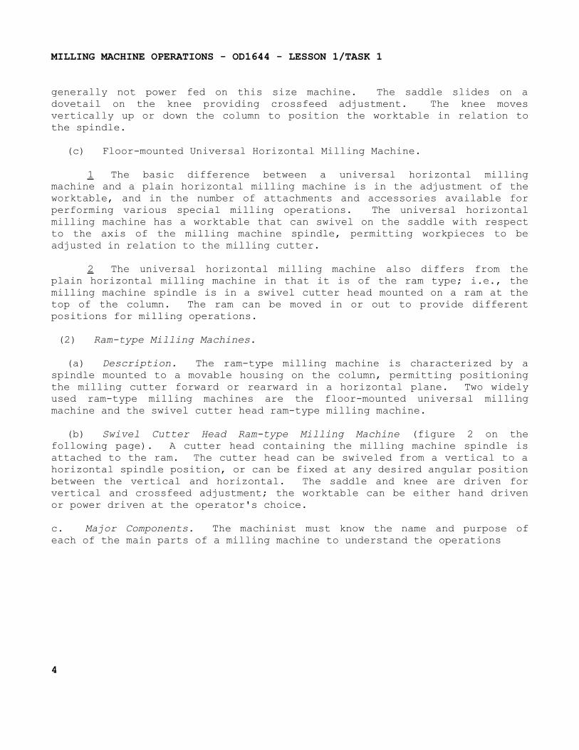
(b) Swivel Cutter Head Ram-type Milling Machine (figure 2 on the following page). A cutter head containing the milling machine spindle is attached to the ram. The cutter head can be swiveled from a vertical to a horizontal spindle position, or can be fixed at any desired angular position between the vertical and horizontal. The saddle and knee are driven for vertical and crossfeed adjustment; the worktable can be either hand driven or power driven at the operator's choice.
c. Major Components. The machinist must know the name and purpose of each of the main parts of a milling machine to understand the operations
4
MILLING MACHINE OPERATIONS - OD1644 - LESSON 1/TASK 1
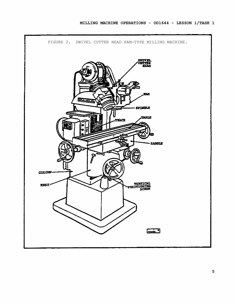
FIGURE 2. SWIVEL CUTTER HEAD RAM-TYPE MILLING MACHINE.
5
MILLING MACHINE OPERATIONS - OD1644 - LESSON 1/TASK 1
discussed in this text. Keep in mind that although we are discussing a knee and a column milling machine, this information can be applied to other types. Use figure 1 on page 3 (which illustrates a plain knee and column milling machine) to help become familiar with the location of the various parts of these machines.
(1) Column. The column, including the base, is the main casting which supports all other parts of the machine. An oil reservoir and a pump in the column keeps the spindle lubricated. The column rests on a base that contains a coolant reservoir and a pump that can be used when performing any machining operation that requires a coolant.
(2) Knee. The knee is the casting that supports the table and the saddle. The feed change gearing is enclosed within the knee. It is supported and can be adjusted by the elevating screw. The knee is fastened to the column by dovetail ways. The lever can be raised or lowered either by hand or power feed. The hand feed is usually used to take the depth of cut or to position the work, and the power feed to move the work during the machining operation.
(3) Saddle and Swivel Table. The saddle slides on a horizontal dovetail, parallel to the axis of the spindle, on the knee. The swivel table (on universal machines only) is attached to the saddle and can be swiveled approximately 45° in either direction.
(4) Power Feed Mechanism. The power feed mechanism is contained in the knee and controls the longitudinal, transverse (in and out) and vertical feeds. The desired rate of feed can be obtained on the machine by positioning the feed selection levers as indicated on the feed selection plates. On some universal knee and column milling machines the feed is obtained by turning the speed selection handle until the desired rate of feed is indicated on the feed dial. Most milling machines have a rapid traverse lever that can be engaged when a temporary increase in speed of the longitudinal, transverse, or vertical feeds is required. For example, this lever would be engaged when positioning or aligning the work.
6
MILLING MACHINE OPERATIONS - OD1644 - LESSON 1/TASK 1
NOTEFor safety reasons, extreme caution should be exercised while using the rapid traverse controls.
(5) Table. The table is the rectangular casting located on top of the saddle. It contains several T-slots for fastening the work or workholding devices. The table can be moved by hand or by power. To move the table by hand, engage and turn the longitudinal hand crank. To move it by power, engage the longitudinal directional feed control lever. The longitudinal directional control lever can be positioned to the left, to the right, or in the center. Place the end of the directional feed control lever to the left to feed the table to the left. Place it to the right to feed the table to the right. Place it in the center position to disengage the power feed, or to feed the table by hand.
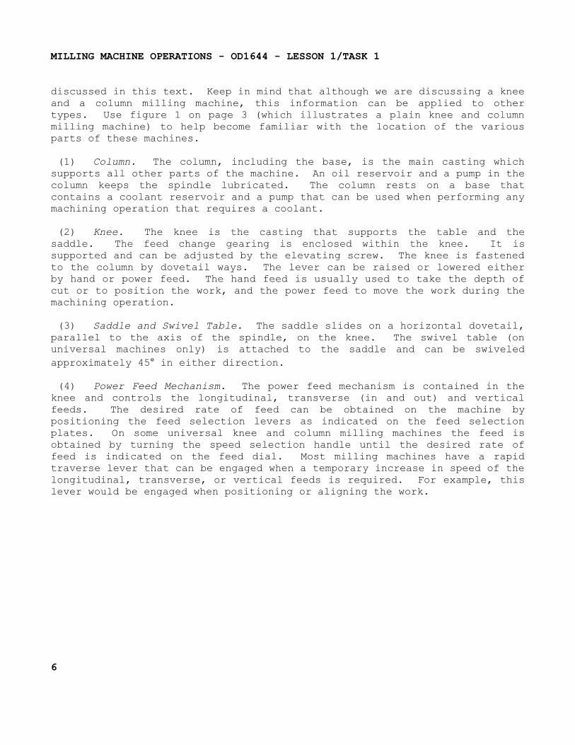
(6) Spindle. The spindle holds and drives the various cutting tools. It is a shaft, mounted on bearings supported by the column. The spindle is driven by an electric motor through a train of gears, all mounted within the column. The front end of the spindle, which is near the table, has an internal taper machined on it. The internal taper (3 1/2 inches per foot) permits mounting tapered-shank cutter holders and cutter arbors. Two keys, located on the face of the spindle, provide a positive drive for the cutter holder, or arbor. The holder or arbor is secured in the spindle by a drawbolt and jamnut, as shown in figure 3 on the following page. Large face mills are sometimes mounted directly to the spindle nose.
(7) Overarm. The overarm is the horizontal beam to which the arbor support is fastened. The overarm, may be a single casting that slides in the dovetail ways on the top of the column. It may consist of one or two cylindrical bars that slide through the holes in the column. On some machines to position the overarm, first unclamp the locknuts and then extend the overarm by turning a crank. On others, the overarm is moved by merely pushing on it. The overarm should only be extended far enough to so position the arbor support as to make the setup as rigid as possible. To place the arbor supports on an overarm, extend one of the bars approximately 1-inch farther than the other bar.
7
MILLING MACHINE OPERATIONS - OD1644 - LESSON 1/TASK 1
FIGURE 3. TAPERS USED FOR MILLING MACHINES.
Always tighten the locknuts after the overarm is positioned. On some milling machines, the coolant supply nozzle is fastened to the overarm. The nozzle can be mounted with a split clamp to the overarm after the arbor support has been placed in position.
(8) Arbor Support. The arbor support is a casting containing a bearing which aligns the outer end of the arbor with the spindle. This helps to keep the arbor from springing during cutting operations. Two types of arbor supports are commonly used. One type has a small diameter bearing hole, usually 1-inch maximum in diameter. The other type has a large diameter bearing hole, usually up to 2 3/4 inches. An oil reservoir in the arbor support keeps the bearing surfaces lubricated. An arbor support can be clamped
8
MILLING MACHINE OPERATIONS - OD1644 - LESSON 1/TASK 1
anywhere on the overarm. Small arbor supports give additional clearance below the arbor supports when small diameter cutters are being used. Small arbor supports can provide support only at the extreme end of the arbor, for this reason they are not recommended for general use. Large arbor supports can be positioned at any point on the arbor. Therefore they can provide support near the cutter, if necessary. The large arbor support should be positioned as close to the cutter as possible, to provide a rigid tooling setup. Although arbor supports are not classified, a general rule of thumb can be used for arbor selection--the old reference type A is of a small bearing diameter, and the old reference type B is of a large bearing diameter.
NOTETo prevent bending or springing of the arbor, you must install the arbor support before loosening or tightening the arbor nut.
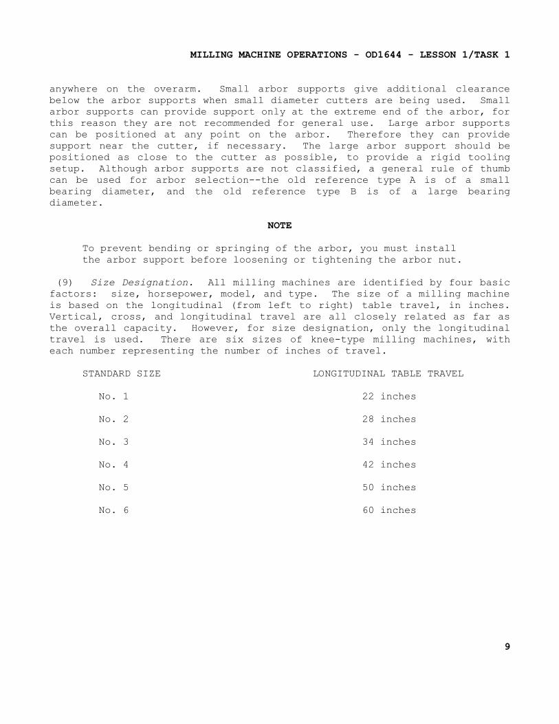
(9) Size Designation. All milling machines are identified by four basic factors: size, horsepower, model, and type. The size of a milling machine is based on the longitudinal (from left to right) table travel, in inches. Vertical, cross, and longitudinal travel are all closely related as far as the overall capacity. However, for size designation, only the longitudinal travel is used. There are six sizes of knee-type milling machines, with each number representing the number of inches of travel.
STANDARD SIZE LONGITUDINAL TABLE TRAVEL
No. 1 22 inches
No. 2 28 inches
No. 3 34 inches
No. 4 42 inches
No. 5 50 inches
No. 6 60 inches
9
MILLING MACHINE OPERATIONS - OD1644 - LESSON 1/TASK 1
If the milling machine in the shop is labeled No. 2HL, it has a table travel of 28 inches; if it is labeled No. 5LD, it has a travel of 50 inches. The horsepower designation refers to the rating of the motor which is used to power the machine. The model designation is determined by the manufacturer and features vary with different brands. The type of milling machine is designated as plain or universal, horizontal or vertical, and knee and column, or bed. In addition, machines may have other special type designations and, therefore, may not fit any standard classification.
3. Milling Machine Accessories And Attachments
a. Arbors. Milling machine cutters can be mounted on several types of holding device. The machinist must know the devices, and the purpose of each to make the most suitable tooling setup for the operation to be performed. Technically, an arbor is a shaft on which a cutter is mounted. For convenience, since there are so few types of cutter holders that are not arbors, we will refer to all types of cutter holding devices as arbors.
(1) Description.
(a) Milling machine arbors are made in various lengths and in standard diameters of 7/8, 1, 1 1/4, and 1 1/2 inch. The shank is made to fit the tapered hole in the spindle, the other end is threaded.
NOTEThe threaded end may have left-handed or right-handed threads.
(b) Arbors are supplied with one of three tapers to fit the milling machine spindle (figure 4 on the following page), the milling machines Standard taper, the Brown and Sharpe taper, and the Brown and Sharpe taper with tang.
(c) The milling machine Standard taper is used on most machines of recent manufacture. It was originated and designed by the milling machine manufacturers to make removal of the arbor from the spindle much easier than will those of earlier design.
10
MILLING MACHINE OPERATIONS - OD1644 - LESSON 1/TASK 1
(d) The Brown and Sharpe taper is found mostly on older machines. Adapters or collets are used to adapt these tapers to fit the machines whose spindles have milling machine Standard tapers.
(e) The Brown and Sharpe taper with tang also is used on some of the older machines. The tang engages a slot in the spindle to assist in driving the arbor.
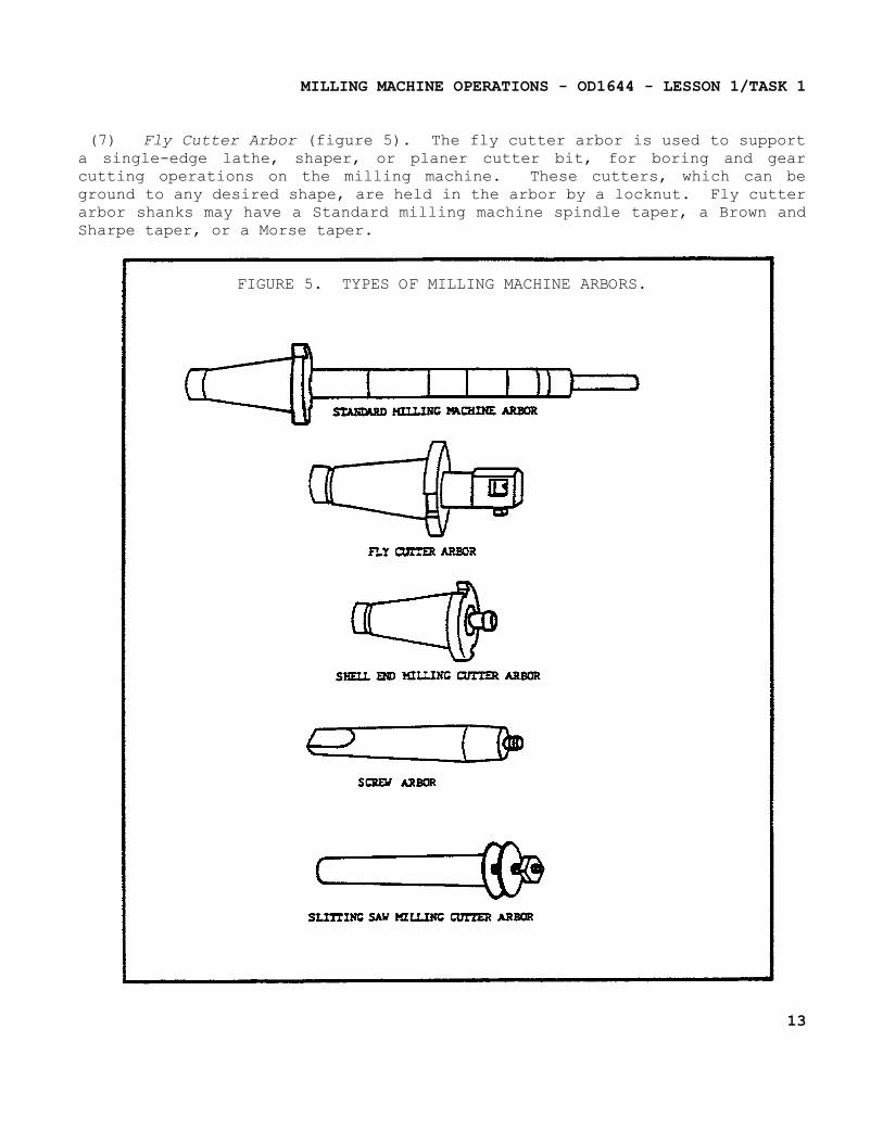
(2) Standard Milling Machine Arbor (figure 4 below, and figure 5 on page 13).
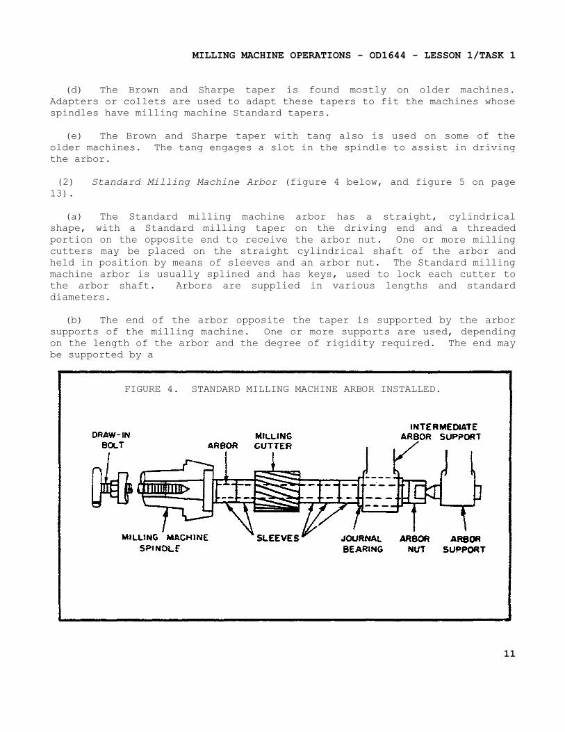
(a) The Standard milling machine arbor has a straight, cylindrical shape, with a Standard milling taper on the driving end and a threaded portion on the opposite end to receive the arbor nut. One or more milling cutters may be placed on the straight cylindrical shaft of the arbor and held in position by means of sleeves and an arbor nut. The Standard milling machine arbor is usually splined and has keys, used to lock each cutter to the arbor shaft. Arbors are supplied in various lengths and standard diameters.
(b) The end of the arbor opposite the taper is supported by the arbor supports of the milling machine. One or more supports are used, depending on the length of the arbor and the degree of rigidity required. The end may be supported by a
FIGURE 4. STANDARD MILLING MACHINE ARBOR INSTALLED.
11
MILLING MACHINE OPERATIONS - OD1644 - LESSON 1/TASK 1
lathe center, bearing against the arbor nut (figure 4 on the previous page) or by a bearing surface of the arbor fitting inside a bushing of the arbor support. Journal bearings are placed over the arbor in place of sleeves where an intermediate arbor support is positioned.
(c) The most common means of fastening the arbor in the milling machine spindle is by use of a draw-in bolt (figure 4). The bolt threads into the taper shank of the arbor to draw the taper into the spindle and hold it in place. Arbors secured in this manner are removed by backing out the draw-in bolt and tapping the end of the bolt to loosen the taper.
(3) Screw Arbor (figure 5 on the following page). Screw arbors are used to hold small cutters that have threaded holes. These arbors have a taper next to the threaded portion to provide alignment and support for tools that require a nut to hold them against a tapered surface. A right-hand threaded arbor must be used for right-hand cutters; a left-hand threaded arbor is used to mount left-hand cutters.
(4) Slitting Saw Milling Cutter Arbor (figure 5). The slitting saw milling cutter arbor is a short arbor having two flanges between which the milling cutter is secured by tightening a clamping nut. This arbor is used to hold the metal slitting saw milling cutters that are used for slotting, slitting, and sawing operations.
(5) End Milling Cutter Arbor. The end milling cutter arbor has a bore in the end in which the straight shank end milling cutters fit. The end milling cutters are locked in place by means of a setscrew.
(6) Shell End Milling Cutter Arbor (figure 5). Shell end milling arbors are used to hold and drive shell end milling cutters. The shell end milling cutter is fitted over the short boss on the arbor shaft and is held against the face of the arbor by a bolt, or a retaining screw. The two lugs on the arbor fit slots in the cutter to prevent the cutter from rotating on the arbor during the machining operation. A special wrench is used to tighten and loosen a retaining screw/bolt in the end of the arbor.
12
MILLING MACHINE OPERATIONS - OD1644 - LESSON 1/TASK 1
(7) Fly Cutter Arbor (figure 5). The fly cutter arbor is used to support a single-edge lathe, shaper, or planer cutter bit, for boring and gear cutting operations on the milling machine. These cutters, which can be ground to any desired shape, are held in the arbor by a locknut. Fly cutter arbor shanks may have a Standard milling machine spindle taper, a Brown and Sharpe taper, or a Morse taper.
FIGURE 5. TYPES OF MILLING MACHINE ARBORS.
13
MILLING MACHINE OPERATIONS - OD1644 - LESSON 1/TASK 1
b. Collets and Spindles.
(1) Description. Milling cutters that contain their own straight or tapered shanks are mounted to the milling machine spindle with collets or spindle adapters which adapt the cutter shank to the spindle.
(2) Collets. Collets for milling machines serve to step up or increase the taper sizes so that small-shank tools can be fitted into large spindle recesses. They are similar to drilling machine sockets and sleeves except that their tapers are not alike. Spring collets are used to hold and drive straight-shanked tools. The spring collet chuck consists of a collet adapter, spring collets, and a cup nut. Spring collets are similar to lathe collets. The cup forces the collet into the mating taper, causing the collet to close on the straight shank of the tool. Collets are available in several fractional sizes.
(3) Spindle Adapters. Spindle adapters are used to adapt arbors and milling cutters to the standard tapers used for milling machine spindles. With the proper spindle adapters, any tapered or straight shank cutter or arbor can be fitted to any milling machine, if the sizes and tapers are standard.
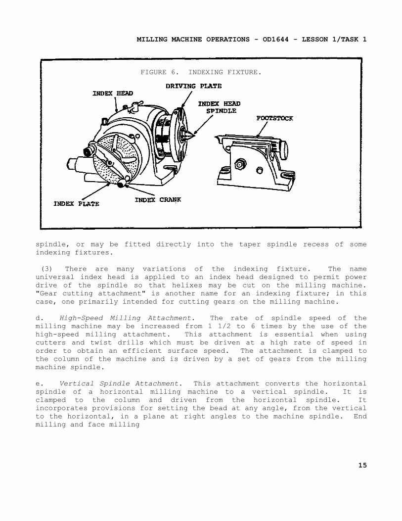
c. Indexing Fixture (figure 6 on the following page).
(1) The indexing fixture is an indispensable accessory for the milling machine. Basically, it is a device for mounting workpieces and rotating them a specified amount around the workpiece's axis, as from one tooth space to another on a gear or cutter.
(2) The index fixture consists of an index head, also called a dividing head, and a footstock, similar to the tailstock of a lathe. The index head and the footstock are attached to the worktable of the milling machine by T-slot bolts. An index plate containing graduations is used to control the rotation of the index head spindle. The plate is fixed to the index head, and an index crank, connected to the index head spindle by a worm gear and shaft, is moved about the index plate. Workpieces are held between centers by the index head spindle and footstock. Workpieces may also be held in a chuck mounted to the index head
14
MILLING MACHINE OPERATIONS - OD1644 - LESSON 1/TASK 1
FIGURE 6. INDEXING FIXTURE.
spindle, or may be fitted directly into the taper spindle recess of some indexing fixtures.
(3) There are many variations of the indexing fixture. The name universal index head is applied to an index head designed to permit power drive of the spindle so that helixes may be cut on the milling machine. "Gear cutting attachment" is another name for an indexing fixture; in this case, one primarily intended for cutting gears on the milling machine.
d. High-Speed Milling Attachment. The rate of spindle speed of the milling machine may be increased from 1 1/2 to 6 times by the use of the high-speed milling attachment. This attachment is essential when using cutters and twist drills which must be driven at a high rate of speed in order to obtain an efficient surface speed. The attachment is clamped to the column of the machine and is driven by a set of gears from the milling machine spindle.
e. Vertical Spindle Attachment. This attachment converts the horizontal spindle of a horizontal milling machine to a vertical spindle. It is clamped to the column and driven from the horizontal spindle. It incorporates provisions for setting the bead at any angle, from the vertical to the horizontal, in a plane at right angles to the machine spindle. End milling and face milling
15
MILLING MACHINE OPERATIONS - OD1644 - LESSON 1/TASK 1
operations are more easily accomplished with this attachment, due to the fact that the cutter and the surface being cut are in plain view.
f. Universal Milling Attachment. This device is similar to the vertical spindle attachment but is more versatile. The cutter head can be swiveled to any angle in any plane, whereas the vertical spindle attachment only rotates in one plane from the horizontal to the vertical.
g. Circular Milling Attachment. This attachment consists of a circular worktable containing T-slots for mounting workpieces. The circular table revolves on a base attached to the milling machine worktable. The attachment can be either hand or power driven, being connected to the table drive shaft if power driven. It may be used for milling circles, arcs, segments, and circular slots, as well as for slotting internal and external gears. The table of the attachment is divided in degrees.
h. Offset Boring Head. The offset boring head is an attachment that fits to the milling machine spindle and permits a single-edge cutting tool, such as a lathe cutter bit, to be mounted off-center on the milling machine. Workpieces can be mounted in a vise attached to the worktable and can be bored with this attachment.
4. Mounting and Indexing Work
a. General.
(1) An efficient and positive method of holding workpieces to the milling machine table is essential if the machine tool is to be used to advantage. Regardless of the method used in holding, there are certain factors that should be observed in every case. The workpiece must not be sprung in clamping; it must be secured to prevent it from springing or moving away from the cutter; and it must be so aligned that it may be correctly machined.
(2) Milling machine worktables are provided with several T-slots, used either for clamping and locating the workpiece itself or for mounting various holding devices and attachments. These T-slots extend the length of the table and are parallel to its line of travel. Most milling machine attachments, such as vises and index
16
MILLING MACHINE OPERATIONS - OD1644 - LESSON 1/TASK 1
fixtures, have keys or tongues on the underside of their bases so that they may be located correctly in relation to the T-slots.
b. Methods of Mounting Workpieces.
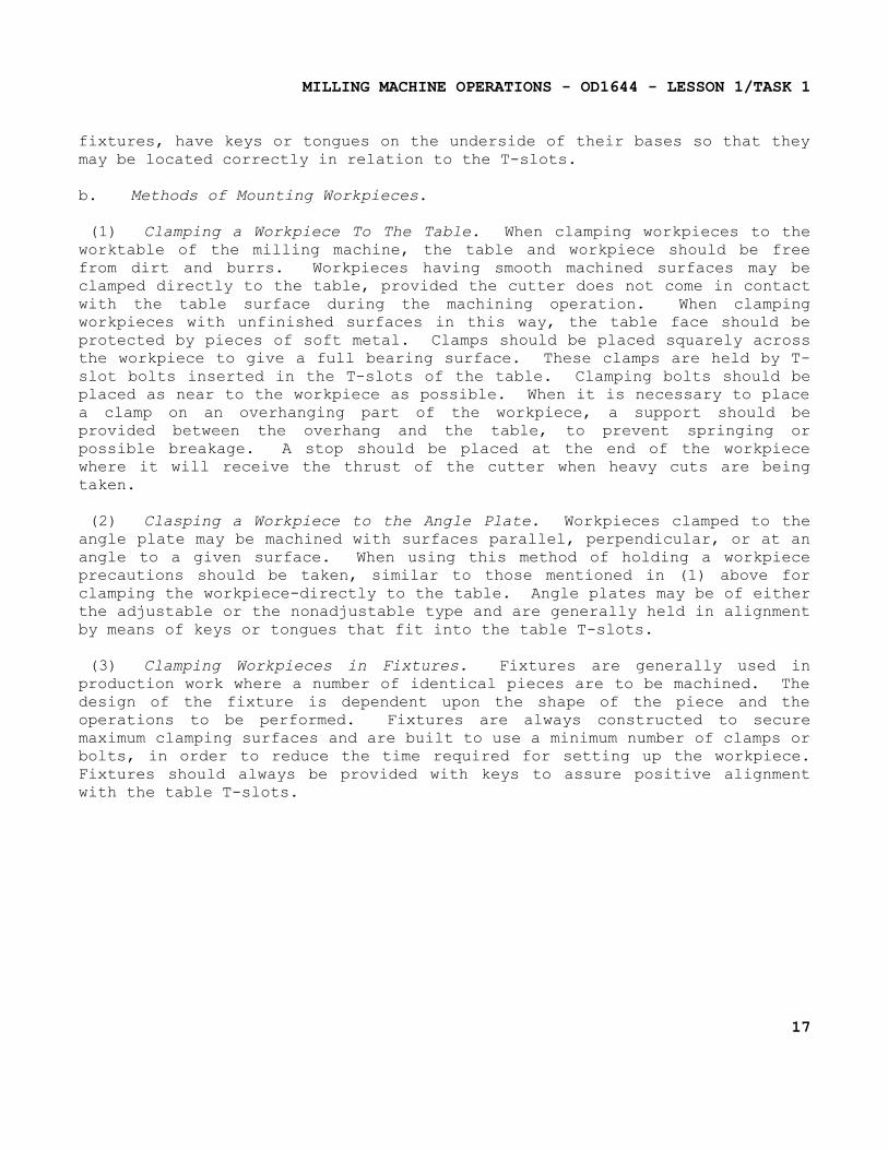
(1) Clamping a Workpiece To The Table. When clamping workpieces to the worktable of the milling machine, the table and workpiece should be free from dirt and burrs. Workpieces having smooth machined surfaces may be clamped directly to the table, provided the cutter does not come in contact with the table surface during the machining operation. When clamping workpieces with unfinished surfaces in this way, the table face should be protected by pieces of soft metal. Clamps should be placed squarely across the workpiece to give a full bearing surface. These clamps are held by T-slot bolts inserted in the T-slots of the table. Clamping bolts should be placed as near to the workpiece as possible. When it is necessary to place a clamp on an overhanging part of the workpiece, a support should be provided between the overhang and the table, to prevent springing or possible breakage. A stop should be placed at the end of the workpiece where it will receive the thrust of the cutter when heavy cuts are being taken.
(2) Clasping a Workpiece to the Angle Plate. Workpieces clamped to the angle plate may be machined with surfaces parallel, perpendicular, or at an angle to a given surface. When using this method of holding a workpiece precautions should be taken, similar to those mentioned in (1) above for clamping the workpiece-directly to the table. Angle plates may be of either the adjustable or the nonadjustable type and are generally held in alignment by means of keys or tongues that fit into the table T-slots.
(3) Clamping Workpieces in Fixtures. Fixtures are generally used in production work where a number of identical pieces are to be machined. The design of the fixture is dependent upon the shape of the piece and the operations to be performed. Fixtures are always constructed to secure maximum clamping surfaces and are built to use a minimum number of clamps or bolts, in order to reduce the time required for setting up the workpiece. Fixtures should always be provided with keys to assure positive alignment with the table T-slots.
17
MILLING MACHINE OPERATIONS - OD1644 - LESSON 1/TASK 1
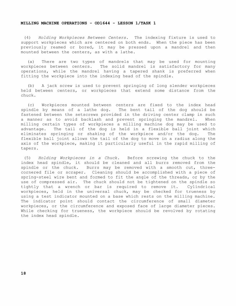
(4) Holding Workpieces Between Centers. The indexing fixture is used to support workpieces which are centered on both ends. When the piece has been previously reamed or bored, it may be pressed upon a mandrel and then mounted between the centers, as with a lathe.
(a) There are two types of mandrels that may be used for mounting workpieces between centers. The solid mandrel is satisfactory for many operations, while the mandrel having a tapered shank is preferred when fitting the workpiece into the indexing head of the spindle.
(b) A jack screw is used to prevent springing of long slender workpieces held between centers, or workpieces that extend some distance from the chuck.
(c) Workpieces mounted between centers are fixed to the index head spindle by means of a lathe dog. The bent tail of the dog should be fastened between the setscrews provided in the driving center clamp in such a manner as to avoid backlash and prevent springing the mandrel. When milling certain types of workpieces a milling machine dog may be used to advantage. The tail of the dog is held in a flexible ball joint which eliminates springing or shaking of the workpiece and/or the dog. The flexible ball joint allows the tail of the dog to move in a radius along the axis of the workpiece, making it particularly useful in the rapid milling of tapers.
(5) Holding Workpieces in a Chuck. Before screwing the chuck to the index head spindle, it should be cleaned and all burrs removed from the spindle or the chuck. Burrs may be removed with a smooth cut, three-cornered file or scraper. Cleaning should be accomplished with a piece of spring-steel wire bent and formed to fit the angle of the threads, or by the use of compressed air. The chuck should not be tightened on the spindle so tightly that a wrench or bar is required to remove it. Cylindrical workpieces, held in the universal chuck, may be checked for trueness by using a test indicator mounted on a base which rests on the milling machine. The indicator point should contact the circumference of small diameter workpieces, or the circumference and exposed face of large diameter pieces. While checking for trueness, the workpiece should be revolved by rotating the index head spindle.
18
MILLING MACHINE OPERATIONS - OD1644 - LESSON 1/TASK 1
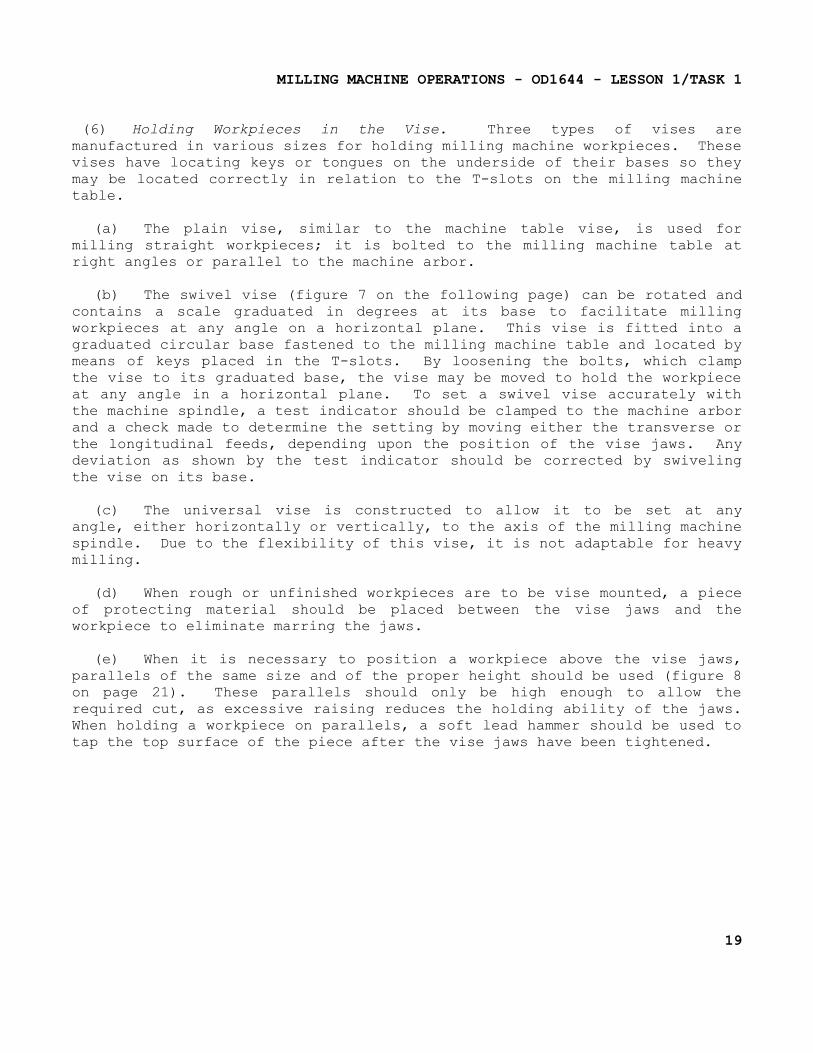
(6) Holding Workpieces in the Vise. Three types of vises are manufactured in various sizes for holding milling machine workpieces. These vises have locating keys or tongues on the underside of their bases so they may be located correctly in relation to the T-slots on the milling machine table.
(a) The plain vise, similar to the machine table vise, is used for milling straight workpieces; it is bolted to the milling machine table at right angles or parallel to the machine arbor.
(b) The swivel vise (figure 7 on the following page) can be rotated and contains a scale graduated in degrees at its base to facilitate milling workpieces at any angle on a horizontal plane. This vise is fitted into a graduated circular base fastened to the milling machine table and located by means of keys placed in the T-slots. By loosening the bolts, which clamp the vise to its graduated base, the vise may be moved to hold the workpiece at any angle in a horizontal plane. To set a swivel vise accurately with the machine spindle, a test indicator should be clamped to the machine arbor and a check made to determine the setting by moving either the transverse or the longitudinal feeds, depending upon the position of the vise jaws. Any deviation as shown by the test indicator should be corrected by swiveling the vise on its base.
(c) The universal vise is constructed to allow it to be set at any angle, either horizontally or vertically, to the axis of the milling machine spindle. Due to the flexibility of this vise, it is not adaptable for heavy milling.
(d) When rough or unfinished workpieces are to be vise mounted, a piece of protecting material should be placed between the vise jaws and the workpiece to eliminate marring the jaws.
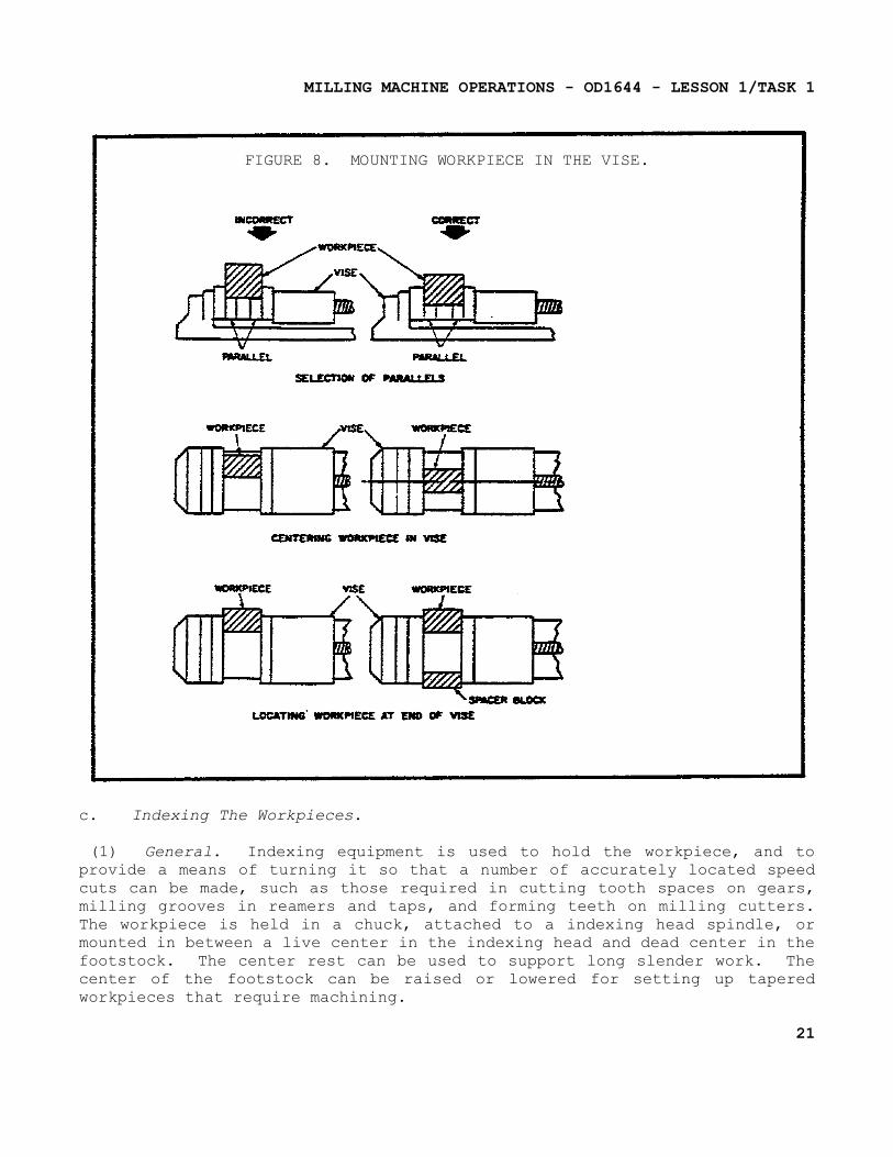
(e) When it is necessary to position a workpiece above the vise jaws, parallels of the same size and of the proper height should be used (figure 8 on page 21). These parallels should only be high enough to allow the required cut, as excessive raising reduces the holding ability of the jaws. When holding a workpiece on parallels, a soft lead hammer should be used to tap the top surface of the piece after the vise jaws have been tightened.
19
MILLING MACHINE OPERATIONS - OD1644 - LESSON 1/TASK 1
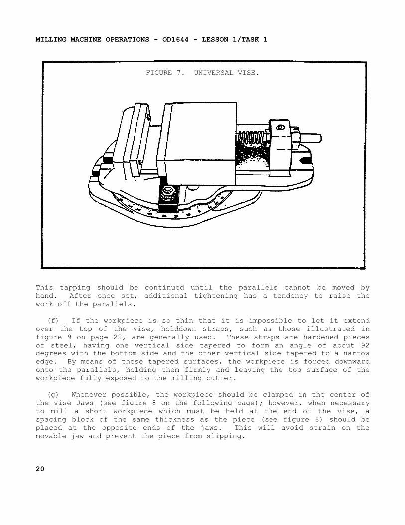
FIGURE 7. UNIVERSAL VISE.
This tapping should be continued until the parallels cannot be moved by hand. After once set, additional tightening has a tendency to raise the work off the parallels.
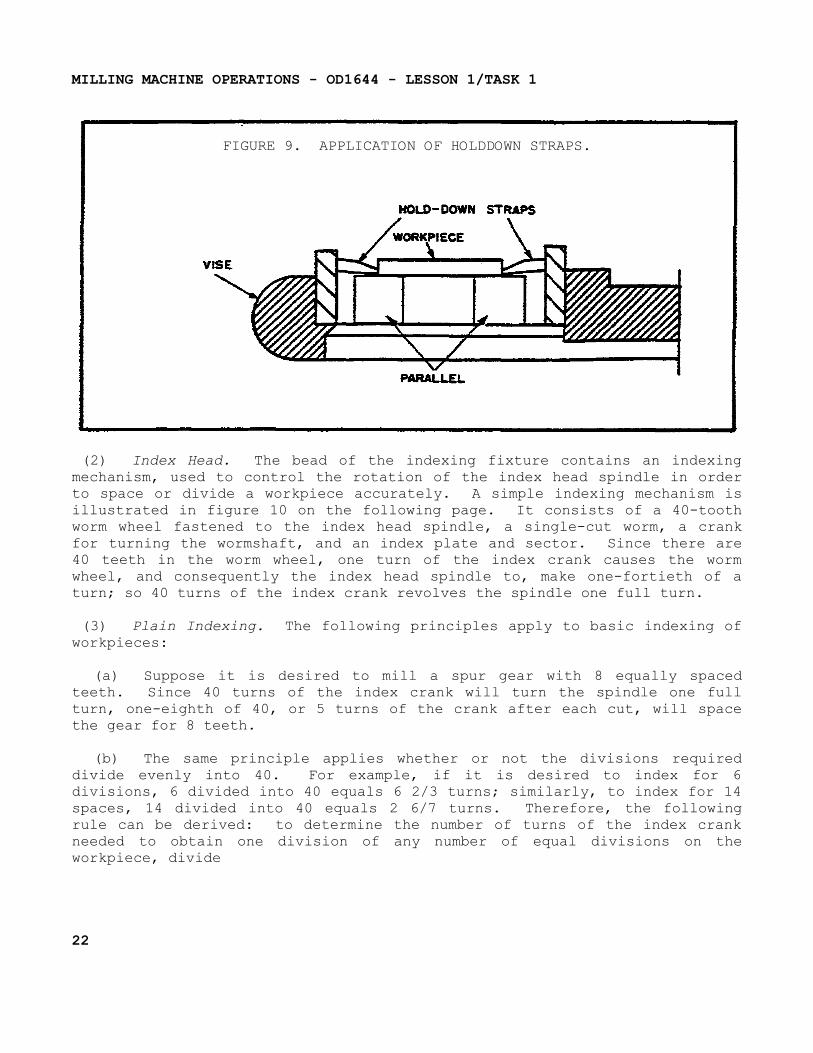
(f) If the workpiece is so thin that it is impossible to let it extend over the top of the vise, holddown straps, such as those illustrated in figure 9 on page 22, are generally used. These straps are hardened pieces of steel, having one vertical side tapered to form an angle of about 92 degrees with the bottom side and the other vertical side tapered to a narrow edge. By means of these tapered surfaces, the workpiece is forced downward onto the parallels, holding them firmly and leaving the top surface of the workpiece fully exposed to the milling cutter.
(g) Whenever possible, the workpiece should be clamped in the center of the vise Jaws (see figure 8 on the following page); however, when necessary to mill a short workpiece which must be held at the end of the vise, a spacing block of the same thickness as the piece (see figure 8) should be placed at the opposite ends of the jaws. This will avoid strain on the movable jaw and prevent the piece from slipping.
20
MILLING MACHINE OPERATIONS - OD1644 - LESSON 1/TASK 1
FIGURE 8. MOUNTING WORKPIECE IN THE VISE.
c. Indexing The Workpieces.
(1) General. Indexing equipment is used to hold the workpiece, and to provide a means of turning it so that a number of accurately located speed cuts can be made, such as those required in cutting tooth spaces on gears, milling grooves in reamers and taps, and forming teeth on milling cutters. The workpiece is held in a chuck, attached to a indexing head spindle, or mounted in between a live center in the indexing head and dead center in the footstock. The center rest can be used to support long slender work. The center of the footstock can be raised or lowered for setting up tapered workpieces that require machining.
21
MILLING MACHINE OPERATIONS - OD1644 - LESSON 1/TASK 1
FIGURE 9. APPLICATION OF HOLDDOWN STRAPS.
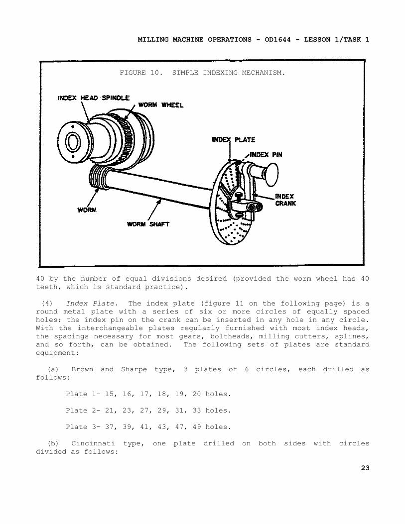
(2) Index Head. The bead of the indexing fixture contains an indexing mechanism, used to control the rotation of the index head spindle in order to space or divide a workpiece accurately. A simple indexing mechanism is illustrated in figure 10 on the following page. It consists of a 40-tooth worm wheel fastened to the index head spindle, a single-cut worm, a crank for turning the wormshaft, and an index plate and sector. Since there are 40 teeth in the worm wheel, one turn of the index crank causes the worm wheel, and consequently the index head spindle to, make one-fortieth of a turn; so 40 turns of the index crank revolves the spindle one full turn.
(3) Plain Indexing. The following principles apply to basic indexing of workpieces:
(a) Suppose it is desired to mill a spur gear with 8 equally spaced teeth. Since 40 turns of the index crank will turn the spindle one full turn, one-eighth of 40, or 5 turns of the crank after each cut, will space the gear for 8 teeth.
(b) The same principle applies whether or not the divisions required divide evenly into 40. For example, if it is desired to index for 6 divisions, 6 divided into 40 equals 6 2/3 turns; similarly, to index for 14 spaces, 14 divided into 40 equals 2 6/7 turns. Therefore, the following rule can be derived: to determine the number of turns of the index crank needed to obtain one division of any number of equal divisions on the workpiece, divide
22
MILLING MACHINE OPERATIONS - OD1644 - LESSON 1/TASK 1
FIGURE 10. SIMPLE INDEXING MECHANISM.
40 by the number of equal divisions desired (provided the worm wheel has 40 teeth, which is standard practice).
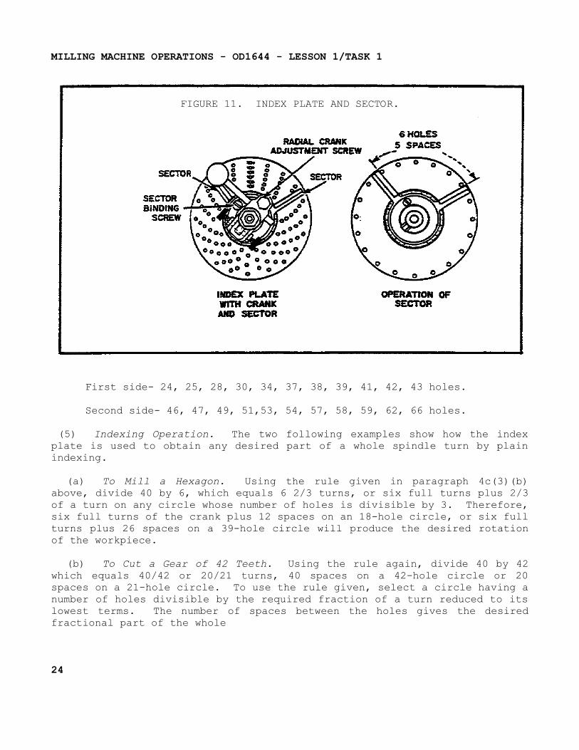
(4) Index Plate. The index plate (figure 11 on the following page) is a round metal plate with a series of six or more circles of equally spaced holes; the index pin on the crank can be inserted in any hole in any circle. With the interchangeable plates regularly furnished with most index heads, the spacings necessary for most gears, boltheads, milling cutters, splines, and so forth, can be obtained. The following sets of plates are standard equipment:
(a) Brown and Sharpe type, 3 plates of 6 circles, each drilled as follows:
Plate 1- 15, 16, 17, 18, 19, 20 holes.
Plate 2- 21, 23, 27, 29, 31, 33 holes.
Plate 3- 37, 39, 41, 43, 47, 49 holes.
(b) Cincinnati type, one plate drilled on both sides with circles divided as follows:
23
MILLING MACHINE OPERATIONS - OD1644 - LESSON 1/TASK 1
FIGURE 11. INDEX PLATE AND SECTOR.
First side- 24, 25, 28, 30, 34, 37, 38, 39, 41, 42, 43 holes.
Second side- 46, 47, 49, 51,53, 54, 57, 58, 59, 62, 66 holes.
(5) Indexing Operation. The two following examples show how the index plate is used to obtain any desired part of a whole spindle turn by plain indexing.
(a) To Mill a Hexagon. Using the rule given in paragraph 4c(3)(b) above, divide 40 by 6, which equals 6 2/3 turns, or six full turns plus 2/3 of a turn on any circle whose number of holes is divisible by 3. Therefore, six full turns of the crank plus 12 spaces on an 18-hole circle, or six full turns plus 26 spaces on a 39-hole circle will produce the desired rotation of the workpiece.
(b) To Cut a Gear of 42 Teeth. Using the rule again, divide 40 by 42 which equals 40/42 or 20/21 turns, 40 spaces on a 42-hole circle or 20 spaces on a 21-hole circle. To use the rule given, select a circle having a number of holes divisible by the required fraction of a turn reduced to its lowest terms. The number of spaces between the holes gives the desired fractional part of the whole
24
MILLING MACHINE OPERATIONS - OD1644 - LESSON 1/TASK 1
circle. When counting holes, start with the first hole ahead of the index pin.
(6) Sector. The sector (figure 11 on the previous page) indicates the next hole in which the pin is to be inserted and makes it unnecessary to count the holes when moving the index crank after each cut. It consists of two radial, beveled arms which can be set at any angle to each other and then moved together around the center of the index plate. Assume that it is desired to make a series of cuts, moving the index crank 1 1/4 turns after each cut. Since the circle has 20 turns, the crank must be turned one full turn plus 5 spaces after each cut. Set the sector arms to include the desired fractional part of a turn, or 5 spaces, between the beveled edges of its arms. If the first cut is taken with the index pin against the left-hand arm, to take the next cut, move the pin once around the circle and into the hole against the right-hand arm of the sector. Before taking the second cut, move the arms so that the left-hand arm is again against the pin; this moves the right-hand arm another five spaces ahead of the pin. Then take the second cut; repeat the operation until all the cuts have been completed.
NOTEIt is a good practice always to index clockwise on the plate.
(7) Direct Indexing. The construction of some index heads permits the worm to be disengaged from the worm wheel, making possible a quicker method of indexing, called direct indexing. The index head is provided with a knob which, when turned through part of a revolution, operates an eccentric and disengages the worm. Direct indexing is accomplished by an additional index plate fastened to the index head spindle. A stationary plunger in the index head fits the holes in the index plate. By moving the plate by hand to index directly, the spindle and the workpiece rotate an equal distance. Direct index plates usually have 24 holes and offer a quick means of milling squares, hexagons, taps, etc. Any number of divisions which is a factor of 24 can be indexed quickly and conveniently by the direct indexing method.
25
MILLING MACHINE OPERATIONS - OD1644 - LESSON 1/TASK 1
(8) Differential Indexing. Sometimes a number of divisions are required which cannot be obtained by simple indexing with the index plates regularly supplied. To obtain these divisions a differential index head is used. The index crank is connected to the wormshaft by a train of gears instead of by a direct coupling and with simple indexing. The selection of these gears involves calculations similar to those used in calculating change gear ratio for cutting threads on a lathe.
(9) Angular Indexing.
(a) When you must divide work into degrees or fractions of degrees by plain indexing, remember that one turn of the index crank will rotate a point on the circumference of the work 1/40 of a revolution. Since there are 360° in a circle, one turn of the index crank will revolve the circumference of the work 1/40 of 360°, or 9°. Hence, in using the index plate and fractional parts of a turn, 2 holes in a 18-hole circle equals 10, 1 hole in a 27-hole circle equals 2/3°, 3 holes in a 54-hole circle equals 1/3°. To determine the number of turns, and parts of a turn of the index crank for a desired number of degrees, divide the number of degrees by 9. The quotient will represent the number of complete turns and fractions of a turn that you should rotate the index crank. For example, the calculation for determining 15° when an index plate with a 54-hole circle is available, is as follows:
or one complete turn plus 36 holes on the 54-hole circle. The calculation for determining 13 1/2° when an index plate with an 18-hole circle is available, is as follows:
(b) When indexing angles are given in minutes and approximate divisions are acceptable, movement of the index crank and the proper index plate may be determined by the following calculations:
26
MILLING MACHINE OPERATIONS - OD1644 - LESSON 1/TASK 1
You can determine the number of minutes represented by one turn of the index crank by multiplying the number of degrees covered in one turn of the index crank by 60:
9° x 60 = 540'
Therefore, one turn of the index crank will rotate the index head spindle 540 minutes.
(c) The number of minutes (540) divided by the number of minutes in the division desired, indicates the total number of holes required in the index plate used. (Moving the index crank one hole will rotate the index spindle through the desired number of minutes of the angle.) This method of indexing can be used only for approximate angles since ordinarily the quotient will come out in mixed numbers, or in numbers for which no index plate is available. However, when the quotient is nearly equal to the number of holes in an available index plate, the nearest number of holes can be used and the error will be very small. For example, the calculation for 24 minutes would be:
or one hole on the 22.5-hole circle. Since there is no 22.5-hole circle on the index plate, a 23-hole circle plate would be used.
(d) If a quotient is not approximately equal to an available circle of holes, multiply by any trial number which will give a product equal to the number of holes in one of the available index circles. You can then move the crank the required number of holes to give the desired division. For example, the calculation for determining 54 minutes when an index plate that has a 20-hole circle is available, is as follows:
or 2 holes on the 20-hole circle.
27
MILLING MACHINE OPERATIONS - OD1644 - LESSON 1/TASK 1
5. Milling Machine Operations
a. General. The milling machine is one of the most versatile metalworking machines in a shop. It is capable of performing simple operations, such as milling a flat surface or drilling a hole, or more complex operations, such as milling helical gear teeth. It would be impractical to attempt to discuss all of the operations that a milling machine can do. The success of any milling operation depends to a great extent upon judgment in setting up the job, selecting the proper cutter, and holding the cutter by the best means. Even though we will discuss only the more common operations, the machinist will find that by using a combination of operations, he will be able to produce a variety of work projects. Some fundamental practices have been proved by experience to be necessary for good results on all jobs. Some of these practices are mentioned below.
(1) Before setting up a job, be sure that the workpiece, the table, the taper in the spindle, and arbor or cutter shank, are all clean and free from chips, nicks, or burrs.
(2) Set up every job as close to the milling machine spindle as the circumstances permit.
(3) Do not select a milling cutter of larger diameter than is necessary.
(4) Keep milling cutters sharp at all times.
(5) Do not change feeds or speeds while the milling machine is in operation.
(6) Always lower the table before backing the workpiece under a revolving milling cutter.
(7) Feed the workpiece in a direction opposite to the rotation of the milling cutter, except when milling long or deep slots or when cutting off stock.
(8) Never run a milling cutter backwards.
(9) When using clamps to secure the workpieces, be sure that they are tight and that the workpiece is held so that it will not spring or vibrate while it is being cut.
28
MILLING MACHINE OPERATIONS - OD1644 - LESSON 1/TASK 1
(10) Use a recommended cutting oil liberally.
(11) Keep chips away from the workpiece; brush them out of the way by any convenient means, but do not do so by hand or with waste.
(12) Use good judgment and common sense in planning every job, and profit by previous mistakes.
b. Operations. Milling operations may be classified under four general headings as follows:
(1) Face Milling - machining flat surfaces which are at right angles to the axis of the cutter.
(2) Plain or Slab Milling - machining flat surfaces which are parallel to the axis of the cutter.
(3) Angular Milling - machining flat surfaces which are at an inclination to the axis of the cutter.
(4) Form Milling - machining surfaces having an irregular outline.
c. Speeds For Milling Cutters.
(1) General. The speed of a milling cutter is the distance in feet per minute that each tooth travels as it cuts its chips. The number of spindle revolutions per minute necessary to give a desired peripheral speed on the size of the milling cutter. The best speed is determined by the type of material being cut and the size and type of cutter used. The smoothness of the finish desired and the power available are other factors relating to the cutter speed.
(2) Selecting Proper Cutting Speed.
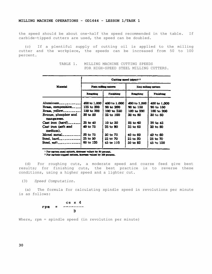
(a) The approximate values given in table 1 on the following page may be used as a guide for selecting the proper cutting speed. If the operator finds that the machine, the milling cutter, or the workpiece cannot be handled suitably at these speeds, immediate readjustment should be made.
(b) Table 1 lists speeds for high-speed steel milling cutters. If carbon steel cutters are used,
29
MILLING MACHINE OPERATIONS - OD1644 - LESSON 1/TASK 1
the speed should be about one-half the speed recommended in the table. If carbide-tipped cutters are used, the speed can be doubled.
(c) If a plentiful supply of cutting oil is applied to the milling cutter and the workpiece, the speeds can be increased from 50 to 100 percent.
TABLE 1. MILLING MACHINE CUTTING SPEEDSFOR HIGH-SPEED STEEL MILLING CUTTERS.
(d) For roughing cuts, a moderate speed and coarse feed give best results; for finishing cuts, the best practice is to reverse these conditions, using a higher speed and a lighter cut.
(3) Speed Computation.
(a) The formula for calculating spindle speed in revolutions per minute is as follows:
Where, rpm = spindle speed (in revolution per minute)
30
MILLING MACHINE OPERATIONS - OD1644 - LESSON 1/TASK 1
cs = cutting speed of milling cutter(in surface feet per minute)
D = diameter of milling cutter (in inches).
For example, the spindle speed for machining a piece of steel at a speed of 35 rpm with a cutter 2 inches in diameter is calculated as follows:
Therefore, the milling machine spindle would be set for as near 70 rpm as possible. If the calculated rpm cannot be obtained, the next lower selection should be made.
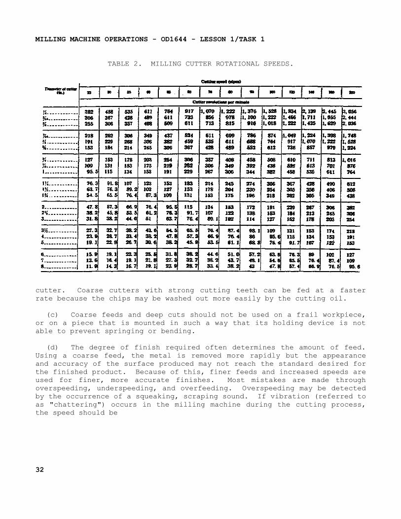
(b) Table 2 on page 32 is provide to facilitate spindle speed computations for standard cutting speeds and standard milling cutters.
d. Feeds For Milling.
(1) General. The rate of feed, or the speed at which the workpiece passes the cutter, determines the time required for cutting a job. In selecting the feed, there are several factors which should be considered. These factors are:
(a) Forces are exerted against the workpiece, the cutter, and their holding devices during the cutting process. The force exerted varies directly with the amount of metal removed and can be regulated by the feed and the depth of cut.
Therefore, the correct amount of feed and depth of cut are interrelated, and in turn are dependent upon the rigidity and power of the machine. Milling machines are limited by the power that they can develop to turn the cutter and the amount of vibration they can resist when using coarse feeds and deep cuts.
(b) The feed and depth of cut also depend upon the type of milling cutter being used. For example, deep cuts or coarse feeds should not be attempted when using a small diameter end milling cutter, as such an attempt would spring or break the
31
MILLING MACHINE OPERATIONS - OD1644 - LESSON 1/TASK 1
TABLE 2. MILLING CUTTER ROTATIONAL SPEEDS.
cutter. Coarse cutters with strong cutting teeth can be fed at a faster rate because the chips may be washed out more easily by the cutting oil.
(c) Coarse feeds and deep cuts should not be used on a frail workpiece, or on a piece that is mounted in such a way that its holding device is not able to prevent springing or bending.
(d) The degree of finish required often determines the amount of feed. Using a coarse feed, the metal is removed more rapidly but the appearance and accuracy of the surface produced may not reach the standard desired for the finished product. Because of this, finer feeds and increased speeds are used for finer, more accurate finishes. Most mistakes are made through overspeeding, underspeeding, and overfeeding. Overspeeding may be detected by the occurrence of a squeaking, scraping sound. If vibration (referred to as "chattering") occurs in the milling machine during the cutting process, the speed should be
32
MILLING MACHINE OPERATIONS - OD1644 - LESSON 1/TASK 1
reduced and the feed increased. Too much cutter clearance, a poorly supported workpiece, or a badly worn machine gear are common causes of "chattering."
(2) Typical Feeds.
(a) Feed for milling cutters will generally run from 0.002 to 0.250 inch per cutter revolution, depending upon the diameter of the cutter, the kind of material, the width and depth of the cut, the size of the workpiece, and the condition of the machine.
(b) Good finishes may be obtained using a 3-inch plain milling cutter at a 40 feet per minute speed, with a feed of 0.040-inch per cutter revolution.
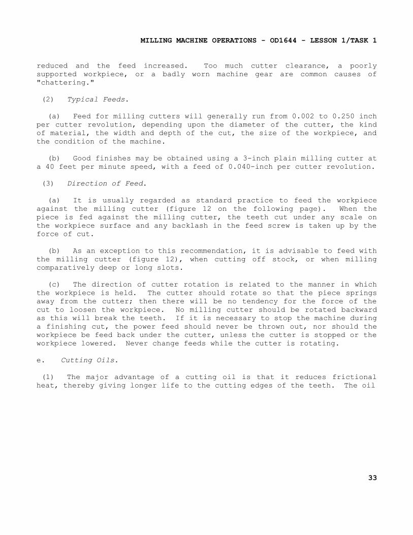
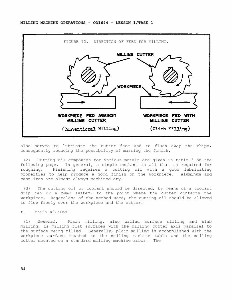
(3) Direction of Feed.
(a) It is usually regarded as standard practice to feed the workpiece against the milling cutter (figure 12 on the following page). When the piece is fed against the milling cutter, the teeth cut under any scale on the workpiece surface and any backlash in the feed screw is taken up by the force of cut.
(b) As an exception to this recommendation, it is advisable to feed with the milling cutter (figure 12), when cutting off stock, or when milling comparatively deep or long slots.
(c) The direction of cutter rotation is related to the manner in which the workpiece is held. The cutter should rotate so that the piece springs away from the cutter; then there will be no tendency for the force of the cut to loosen the workpiece. No milling cutter should be rotated backward as this will break the teeth. If it is necessary to stop the machine during a finishing cut, the power feed should never be thrown out, nor should the workpiece be feed back under the cutter, unless the cutter is stopped or the workpiece lowered. Never change feeds while the cutter is rotating.
e. Cutting Oils.
(1) The major advantage of a cutting oil is that it reduces frictional heat, thereby giving longer life to the cutting edges of the teeth. The oil
33
MILLING MACHINE OPERATIONS - OD1644 - LESSON 1/TASK 1
FIGURE 12. DIRECTION OF FEED FOR MILLING.
also serves to lubricate the cutter face and to flush away the chips, consequently reducing the possibility of marring the finish.
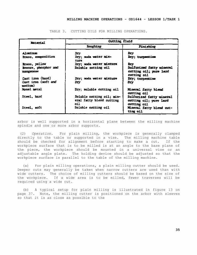
(2) Cutting oil compounds for various metals are given in table 3 on the following page. In general, a simple coolant is all that is required for roughing. Finishing requires a cutting oil with a good lubricating properties to help produce a good finish on the workpiece. Aluminum and cast iron are almost always machined dry.
(3) The cutting oil or coolant should be directed, by means of a coolant drip can or a pump system, to the point where the cutter contacts the workpiece. Regardless of the method used, the cutting oil should be allowed to flow freely over the workpiece and the cutter.
f. Plain Milling.
(1) General. Plain milling, also called surface milling and slab milling, is milling flat surfaces with the milling cutter axis parallel to the surface being milled. Generally, plain milling is accomplished with the workpiece surface mounted to the milling machine table and the milling cutter mounted on a standard milling machine arbor. The
34
MILLING MACHINE OPERATIONS - OD1644 - LESSON 1/TASK 1
TABLE 3. CUTTING OILS FOR MILLING OPERATIONS.
arbor is well supported in a horizontal plane between the milling machine spindle and one or more arbor supports.
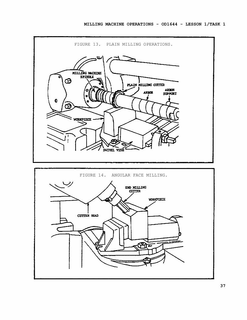
(2) Operation. For plain milling, the workpiece is generally clamped directly to the table or supported in a vise. The milling machine table should be checked for alignment before starting to make a cut. If the workpiece surface that is to be milled is at an angle to the base plane of the piece, the workpiece should be mounted in a universal vise or an adjustable angle plate. The holding device should be adjusted so that the workpiece surface is parallel to the table of the milling machine.
(a) For plain milling operations, a plain milling cutter should be used. Deeper cuts may generally be taken when narrow cutters are used than with wide cutters. The choice of milling cutters should be based on the size of the workpiece. If a wide area is to be milled, fewer traverses will be required using a wide cut.
(b) A typical setup for plain milling is illustrated in figure 13 on page 37. Note, the milling cutter is positioned on the arbor with sleeves so that it is as close as possible to the
35
MILLING MACHINE OPERATIONS - OD1644 - LESSON 1/TASK 1
milling machine spindle, while maintaining sufficient clearance between the vise and the milling machine column. This practice reduces torque in the arbor and permits more rigid support for the cutter.
(c) If large quantities of metal are to be removed, a coarse tooth cutter should be used for roughing and a finer tooth cutter should be used for finishing. A relatively slow cutting speed and a fast table feed should be used for roughing, and a relatively fast cutting speed, and a slow table feed used for finishing. The surface should be checked for accuracy after each completed cut.
g. Angular Milling.
(1) General. Angular milling, or angle milling, is milling flat surfaces which are neither parallel nor perpendicular to the axis of the milling cutter. A single-angle milling cutter (figure 14 on the following page) is used for this operation. Milling dovetails is a typical example of angular milling. When milling dovetails, the usual angle of the cutter is 45°, 50°, 55°, or 60°, based on common dovetail designs.
(2) Operation.
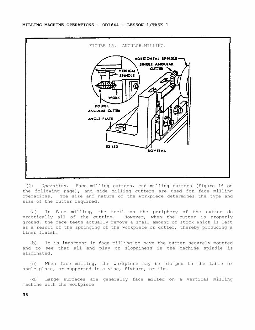
(a) When cutting dovetails on the milling machine, the workpiece may be held in the vice, clamped to the table, or clamped to an angle plate. Figure 15 on page 38 shows the workpiece mounted to a lathe faceplate for angular milling with the milling and grinding lathe attachment. The tongue or groove is first roughed-out using a side milling cutter, after which the angular sides and base are finished with an angle cutter.
(b) In general practice, the dovetail is laid out on the workpiece surface before the milling operation is started. To do this, the required outline should be inscribed and the line prick punched, These lines and punch marks may then be used as a guide during the cutting operation.
h. Face Milling.
(1) General. Face milling, also called end milling and side milling, is machining surfaces perpendicular to the axis of the cutter.
36
MILLING MACHINE OPERATIONS - OD1644 - LESSON 1/TASK 1
FIGURE 13. PLAIN MILLING OPERATIONS.
FIGURE 14. ANGULAR FACE MILLING.
37
MILLING MACHINE OPERATIONS - OD1644 - LESSON 1/TASK 1
FIGURE 15. ANGULAR MILLING.
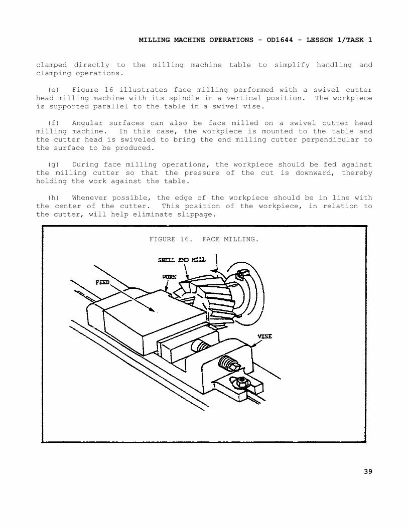
(2) Operation. Face milling cutters, end milling cutters (figure 16 on the following page), and side milling cutters are used for face milling operations. The size and nature of the workpiece determines the type and size of the cutter required.
(a) In face milling, the teeth on the periphery of the cutter do practically all of the cutting. However, when the cutter is properly ground, the face teeth actually remove a small amount of stock which is left as a result of the springing of the workpiece or cutter, thereby producing a finer finish.
(b) It is important in face milling to have the cutter securely mounted and to see that all end play or sloppiness in the machine spindle is eliminated.
(c) When face milling, the workpiece may be clamped to the table or angle plate, or supported in a vise, fixture, or jig.
(d) Large surfaces are generally face milled on a vertical milling machine with the workpiece
38
MILLING MACHINE OPERATIONS - OD1644 - LESSON 1/TASK 1
clamped directly to the milling machine table to simplify handling and clamping operations.
(e) Figure 16 illustrates face milling performed with a swivel cutter head milling machine with its spindle in a vertical position. The workpiece is supported parallel to the table in a swivel vise.
(f) Angular surfaces can also be face milled on a swivel cutter head milling machine. In this case, the workpiece is mounted to the table and the cutter head is swiveled to bring the end milling cutter perpendicular to the surface to be produced.
(g) During face milling operations, the workpiece should be fed against the milling cutter so that the pressure of the cut is downward, thereby holding the work against the table.
(h) Whenever possible, the edge of the workpiece should be in line with the center of the cutter. This position of the workpiece, in relation to the cutter, will help eliminate slippage.
FIGURE 16. FACE MILLING.
39
MILLING MACHINE OPERATIONS - OD1644 - LESSON 1/TASK 1
(i) When setting the depth of the cut, the workpiece should be brought up to just touch the revolving cutter. After a cut has been made from this setting, a measurement of the workpiece is taken. The graduated dial on the traverse feed is then locked and used as a guide in determining the depth of the cut.
1 When starting the cut, the workpiece should be moved so that the cutter is nearly in contact with its edge, after which the automatic feed may be engaged.
2 When a cut is started by hand, care must be taken to avoid pushing the corner of the workpiece between the teeth of the cutter too quickly, as this may result in cutter tooth breakage.
3 In order to prevent time wasting during the operation, the feed trips should be adjusted to stop table travel just as the cutter clears the workpiece.
i. Straddle Milling.
(1) General. When two or more parallel vertical surfaces are machined at a single cut, the operation is called straddle milling. Straddle milling is accomplished by mounting two side milling cutters on the same arbor, set apart so that they straddle the workpiece.
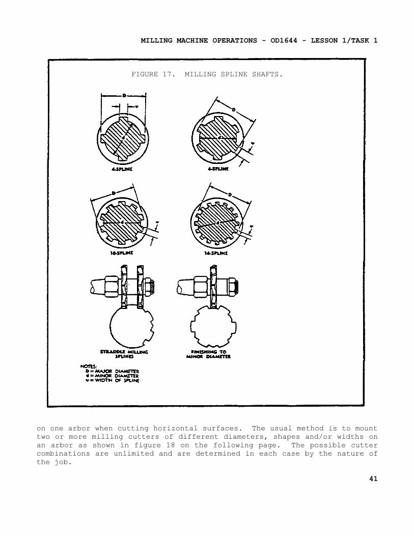
(2) Operation. Figure 17 on the following page illustrates a typical example of straddle milling. In this case a spline is being cut, but the same operation may be applied when cutting squares or hexagons on the end of a cylindrical workpiece. The workpiece is usually mounted between centers in the indexing fixture, or mounted vertically in a swivel vise. The two side milling cutters are separated by spacers, washers, and shims so that the distance between the cutting teeth of the cutters is exactly equal to the width of the workpiece area required. When cutting a square by this method, two opposite sides of the square are cut, then the spindle of the indexing fixture or the swivel vise is rotated 90° and the other two sides of the workpiece are straddle milled.
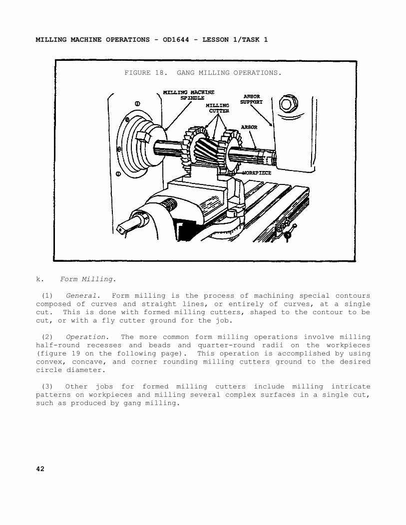
j. Gang Milling.
Gang milling is the term applied to an operation in which two or more milling cutters are used together
40
MILLING MACHINE OPERATIONS - OD1644 - LESSON 1/TASK 1
FIGURE 17. MILLING SPLINE SHAFTS.
on one arbor when cutting horizontal surfaces. The usual method is to mount two or more milling cutters of different diameters, shapes and/or widths on an arbor as shown in figure 18 on the following page. The possible cutter combinations are unlimited and are determined in each case by the nature of the job.
41
MILLING MACHINE OPERATIONS - OD1644 - LESSON 1/TASK 1
FIGURE 18. GANG MILLING OPERATIONS.
k. Form Milling.
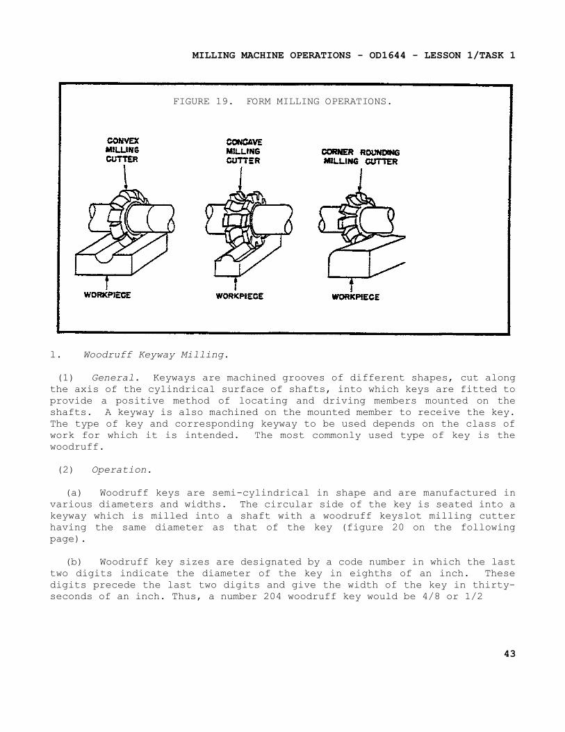
(1) General. Form milling is the process of machining special contours composed of curves and straight lines, or entirely of curves, at a single cut. This is done with formed milling cutters, shaped to the contour to be cut, or with a fly cutter ground for the job.
(2) Operation. The more common form milling operations involve milling half-round recesses and beads and quarter-round radii on the workpieces (figure 19 on the following page). This operation is accomplished by using convex, concave, and corner rounding milling cutters ground to the desired circle diameter.
(3) Other jobs for formed milling cutters include milling intricate patterns on workpieces and milling several complex surfaces in a single cut, such as produced by gang milling.
42
MILLING MACHINE OPERATIONS - OD1644 - LESSON 1/TASK 1
FIGURE 19. FORM MILLING OPERATIONS.
l. Woodruff Keyway Milling.
(1) General. Keyways are machined grooves of different shapes, cut along the axis of the cylindrical surface of shafts, into which keys are fitted to provide a positive method of locating and driving members mounted on the shafts. A keyway is also machined on the mounted member to receive the key. The type of key and corresponding keyway to be used depends on the class of work for which it is intended. The most commonly used type of key is the woodruff.
(2) Operation.
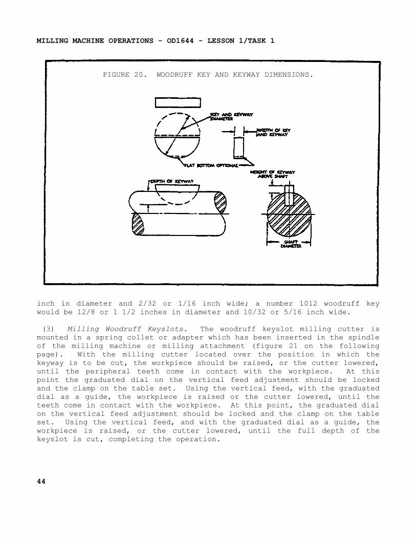
(a) Woodruff keys are semi-cylindrical in shape and are manufactured in various diameters and widths. The circular side of the key is seated into a keyway which is milled into a shaft with a woodruff keyslot milling cutter having the same diameter as that of the key (figure 20 on the following page).
(b) Woodruff key sizes are designated by a code number in which the last two digits indicate the diameter of the key in eighths of an inch. These digits precede the last two digits and give the width of the key in thirty-seconds of an inch. Thus, a number 204 woodruff key would be 4/8 or 1/2
43
MILLING MACHINE OPERATIONS - OD1644 - LESSON 1/TASK 1
FIGURE 20. WOODRUFF KEY AND KEYWAY DIMENSIONS.
inch in diameter and 2/32 or 1/16 inch wide; a number 1012 woodruff key would be 12/8 or 1 1/2 inches in diameter and 10/32 or 5/16 inch wide.
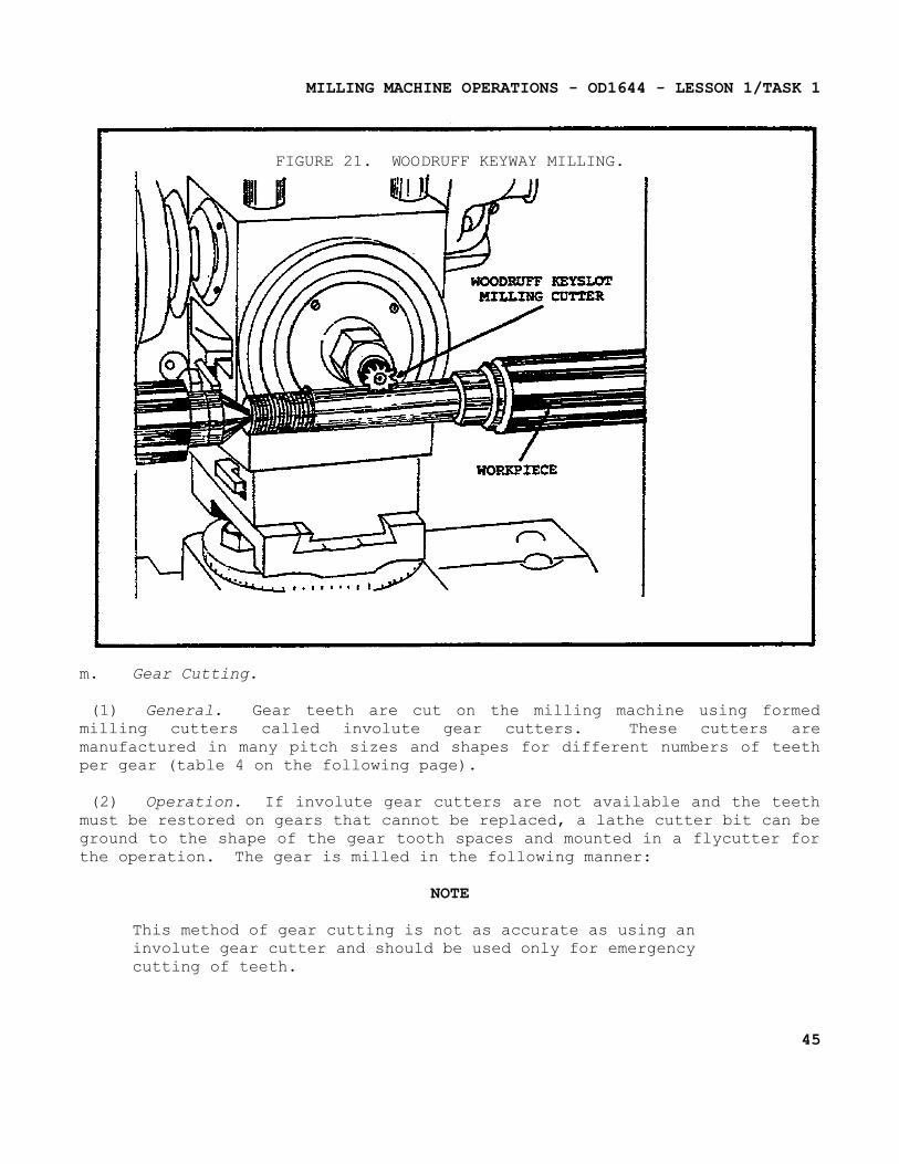
(3) Milling Woodruff Keyslots. The woodruff keyslot milling cutter is mounted in a spring collet or adapter which has been inserted in the spindle of the milling machine or milling attachment (figure 21 on the following page). With the milling cutter located over the position in which the keyway is to be cut, the workpiece should be raised, or the cutter lowered, until the peripheral teeth come in contact with the workpiece. At this point the graduated dial on the vertical feed adjustment should be locked and the clamp on the table set. Using the vertical feed, with the graduated dial as a guide, the workpiece is raised or the cutter lowered, until the teeth come in contact with the workpiece. At this point, the graduated dial on the vertical feed adjustment should be locked and the clamp on the table set. Using the vertical feed, and with the graduated dial as a guide, the workpiece is raised, or the cutter lowered, until the full depth of the keyslot is cut, completing the operation.
44
MILLING MACHINE OPERATIONS - OD1644 - LESSON 1/TASK 1
FIGURE 21. WOODRUFF KEYWAY MILLING.
m. Gear Cutting.
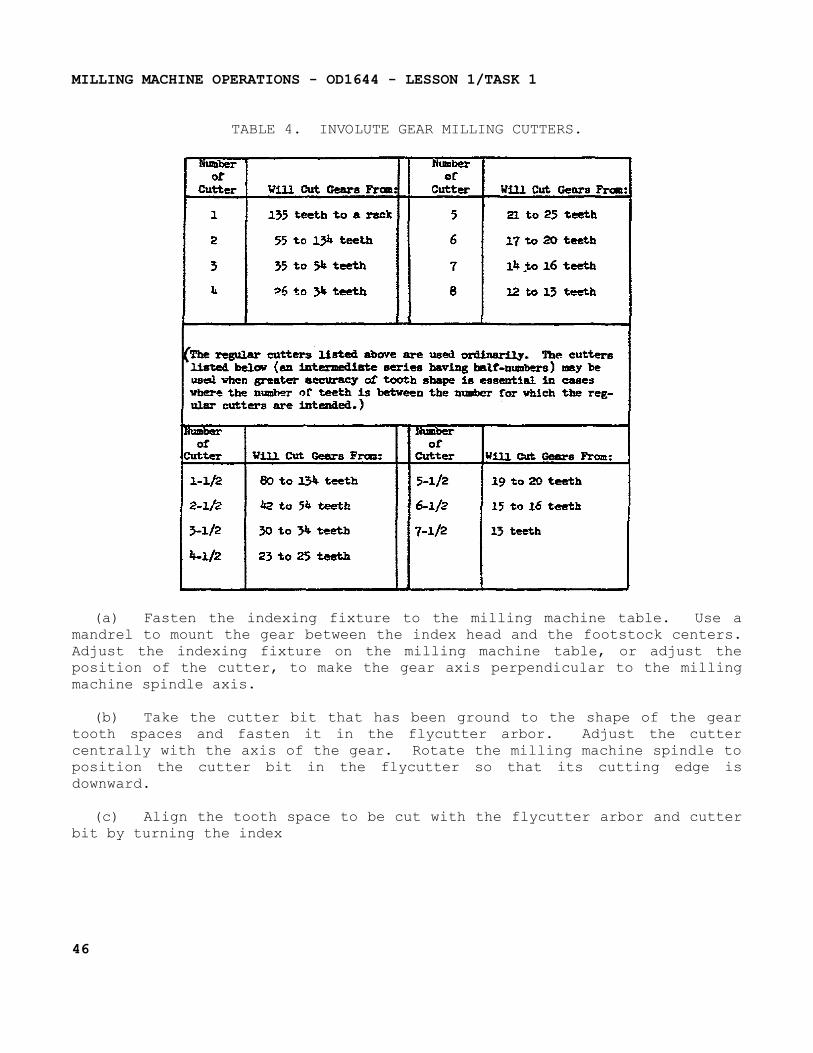
(1) General. Gear teeth are cut on the milling machine using formed milling cutters called involute gear cutters. These cutters are manufactured in many pitch sizes and shapes for different numbers of teeth per gear (table 4 on the following page).
(2) Operation. If involute gear cutters are not available and the teeth must be restored on gears that cannot be replaced, a lathe cutter bit can be ground to the shape of the gear tooth spaces and mounted in a flycutter for the operation. The gear is milled in the following manner:
NOTEThis method of gear cutting is not as accurate as using an involute gear cutter and should be used only for emergency cutting of teeth.
45
MILLING MACHINE OPERATIONS - OD1644 - LESSON 1/TASK 1
TABLE 4. INVOLUTE GEAR MILLING CUTTERS.
(a) Fasten the indexing fixture to the milling machine table. Use a mandrel to mount the gear between the index head and the footstock centers. Adjust the indexing fixture on the milling machine table, or adjust the position of the cutter, to make the gear axis perpendicular to the milling machine spindle axis.
(b) Take the cutter bit that has been ground to the shape of the gear tooth spaces and fasten it in the flycutter arbor. Adjust the cutter centrally with the axis of the gear. Rotate the milling machine spindle to position the cutter bit in the flycutter so that its cutting edge is downward.
(c) Align the tooth space to be cut with the flycutter arbor and cutter bit by turning the index
46
MILLING MACHINE OPERATIONS - OD1644 - LESSON 1/TASK 1
crank on the index head. Proceed to mill the tooth or teeth in the same manner as you would when milling a keyway.
n. Drilling.
(1) General. The milling machine may be used effectively for drilling, since the accurate location of the hole may be secured by means of the feed screw graduations. Spacing holes in a circular path, such as the holes in an indexing plate, may be accomplished by indexing the workpiece with the indexing head that is positioned vertically.
(2) Operation. Twist drills may be supported in drill chucks that are fastened in the milling machine spindle or mounted directly in the milling machine collets or adapters. The workpiece to be drilled is fastened to the milling machine table by means of clamps, vises, or angle plates. Remember, proper speeds and feeds are important functions to consider when performing drilling operations on the milling machine.
o. Boring. Various types of boring toolholders may be used for boring on the milling machine. The boring tool can either be a straight shank, held in chucks and holders, or tapered shanks to fit collets and adapters. The two attachments most commonly used for boring are the flycutter arbor and the offset boring head. The single-edge cutting tool that is used for boring on the milling machine is the same as a lathe cutter bit. Cutting speeds, feeds, and depth of cut should be the same as those prescribed for lathe operations.
6. Milling Machine Adjustments
a. Vertical Milling Machine.
(1) Adjustments.
(a) Proper gib adjustment procedures must be done after 40 hours on new mills.
(b) Each 700 and 800 series of mills have three gibs. One at the front dovetail of the table, one on the left dovetail of the saddle, and one on the left dovetail of the knee. Each gib is supplied with two lock or adjustment screws. The table gib has a
47
MILLING MACHINE OPERATIONS - OD1644 - LESSON 1/TASK 1
lock screw on the right front of the saddle and the adjusting screw on the left front of the saddle.
(c) The saddle gib is at the rear of the saddle on the left side, while the adjusting screw is at the front of the saddle on the left side. The knee gib lock screw is on the bottom of the knee on the left side and the adjusting screw is on the top on the left side.
(d) To adjust the table gib, loosen the table gib lock screw several turns and tighten the adjusting screw on the opposite side of the table until the gib is pressing against the table dovetail. Tighten the lock screw. (Do not tighten the lock screw too tight as it distorts the gib.) Run the table back and forth and check the table for drag. To adjust the saddle and knee, use the same procedures as above.
(2) Adjustments With The Dial Indicator.
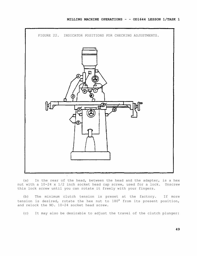
(a) When checking the gibs with a dial indicator, the following checks should be made: (Use figure 22 on the following page as reference.)
(b) With the dial indicator mounted, as in Position 3, the table can be tested for looseness by pulling back and forth on the end of the table. Anything over 0.0015-inch is too much and requires the gibs to be adjusted, also the table should snap back to the "0" reading each time after the table is released.
(c) To check the saddle gib, the indicator should be mounted as in Position 7 and the same tolerance should exist here.
(d) The knee gib will be checked as shown, with the dial indicator in Position 5, by grasping the table and lifting up and pushing down. The reading of deflection here should not be more than 0.0003 of an inch.
(e) As a final check, set the dial indicator on Position 2 and run the table to its extreme right and left positions. The indicator runout should not be more than 0.0015 of an inch.
(3) Quill Feed Clutch. Adjustment of this clutch is as follows:
48
MILLING MACHINE OPERATIONS - - OD1644 LESSON 1/TASK 1
FIGURE 22. INDICATOR POSITIONS FOR CHECKING ADJUSTMENTS.
(a) In the rear of the head, between the head and the adapter, is a hex nut with a 10-24 x 1/2 inch socket head cap screw, used for a lock. Unscrew this lock screw until you can rotate it freely with your fingers.
(b) The minimum clutch tension is preset at the factory. If more tension is desired, rotate the hex nut to 180° from its present position, and relock the NO. 10-24 socket head screw.
(c) It may also be desirable to adjust the travel of the clutch plunger:
49
MILLING MACHINE OPERATIONS - OD1644 - LESSON 1/TASK 1
1 This adjustment is made by means of the 1/4-20 x 3/4 socket set screw immediately behind the feed cam housing.
2 With the clutch disengaged, tighten the set screw (clockwise) while moving the quill down by means of the hand lever until a little roughness can be felt.
(4) Troubleshooting.
NOTEOrdinarily trouble will not manifest itself except when actually working with the machine.
(a) Slide Ways Forking Hard Or Binding.
1 Cause - The gibs are out of adjustment, they are either too tight or too loose. This causes the gib to "wedge."
2 Remedy - Adjust the gibs.
3 Cause - There is dirt in the slide ways.
4 Remedy - Wash out slide ways with light oil.
(b) Chatter Or Vibration When Cutting.
1 Cause - Dirt in the spindle taper, causing a bad fit between the tool holder shank and the spindle taper.
2 Remedy - Clean the spindle taper and the shank of the tool holder.
3 Cause - Faulty shank on the tool holder.
4 Remedy - Replace the shank or dress off the burrs, if they are due to nicks.
5 Cause - Gibs poorly adjusted on the slide ways, or dirty.
6 Remedy - Clean and adjust the gibs as required.
50
MILLING MACHINE OPERATIONS - OD1644 - LESSON 1/TASK 1
7 Cause - Work improperly clamped to the table of the milling machine.
8 Remedy - Check for rocking or movement, and correct by proper clamping.
9 Cause - Improper ground cutting tool.
10 Remedy - Replace or regrind the tool.
11 Cause - Hard spot at the splice of the drive or the worm belts.
12 Remedy - Replace the belts.
13 Cause - Spindle quill worn in the quill head.
14 Remedy - Tighten the quill head lock slightly.
15 Cause - Incorrect spindle speed, table feed, or both.
16 Remedy - Ordinarily, increase the spindle speed and/or increase or decrease the feed to break up the vibration period. Experiment by using the hand feed to feed the table.
17 Cause - Drive pulleys are worn in the grooves or loose on the shafts.
18 Remedy - Replace the pulleys.
(c) Boring or Milling Out Of Square Or At An Angle.
1 Cause - The head is not properly aligned with the table.
2 Remedy - Check the head for alignment and correct.
3 Cause - Work improperly set up; i.e., not square or flat.
4 Remedy - Check and re-align the work.
(d) Failure To Hold The Center Distance When Locating For Boring.
51
MILLING MACHINE OPERATIONS - OD1644 - LESSON 1/TASK 1
1 Cause - Failure to take back-off tension on the lead screw after coming up to the dial indicator reading, causing the table to "creep'; or failure to lock up the slide ways with the same amount of tension after moving the table to a new position.
2 Remedy - Take the back-off tension off from the lead screw after coming up to the indicator reading and lock the table in position.
b. Plain Milling Machine-knee Type.
(1) General. The spindle bearings used in the spindle head are the taper roller type and have been properly adjusted for average conditions before leaving the factory. They should not require readjustment before the machine is to be used. If desired, the end play in the spindle bearings may be checked after a few months of operation in the following manner: Using a lead or composition hammer, gently tap the face of the spindle until all of the play is taken up towards the rear of the machine. Place a dial indicator against the face of the spindle, and then tap the spindle shaft forward from the rear. If the play exceeds 0.001 inch, adjustment may be made as follows:
CAUTIONDo not attempt to take up the spindle bearings without a thorough knowledge of the bearing adjustments and the operating conditions.
(2) Adjustment.
(a) Remove the rear cap from the cutter head.
(b) Loosen the set screws in the bearing head.
(c) Loosen or tighten the nut as necessary to secure the desired adjustment.
(d) Tighten the set screw and reassemble the rear cap on the cutter head.
52
MILLING MACHINE OPERATIONS - OD1644 - LESSON 1/TASK 1
(3) Checking Gib Adjustments.
(a) Gib adjustments should-only be made by those who are thoroughly acquainted with the operation of the machine. In general, all of the gibs should be tight enough to eliminate any and all play, but not so tight that there will be a heavy drag on the working parts. Gibs that are too loose will result in inaccurate work; gibs that are too tight will cause severe wear and strain on the operating mechanisms.
(b) The gibs are properly adjusted at the factory. When readjustment becomes necessary, proceed as follows: The table gib is adjusted by means of two shouldered screws located on each end of the saddle. By first loosening one and then tightening the other, the taper gib may be adjusted as needed. The saddle and knee gibs are adjusted in a similar manner.
(c) The ram gib is adjusted by two adjusting screws. The front and the end screw are the adjusting screws. To adjust the gib, the ram stops must first be removed. These stops are located on the bottom of the ram. To remove the stops, loosen the set screws, which are located on the front and back end of the column, and turn both screws on the gib an equal amount. After proper adjustment has been accomplished, retighten the set screws in the column to hold the adjustment and then replace the ram stops.
(4) Table Feed Screw. Backlash in the table feed screw is adjusted by an adjustable bronze feed screw nut that is located at the left hand end of the saddle. This nut is located in the saddle mechanism just above the saddle binder. To make any desired adjustment, first loosen the check nut and insert a pin in any of the many holes around the flange of the nut. Then turn the screw in either direction until the backlash is from 0.002-inch to 0.005-inch. After you have completed this adjustment, tighten the check nut.
(5) Saddle Feed Screw. The saddle feed screw is adjusted by means of a bronze adjusting nut. This adjusting nut is located in the rear end of the bracket which is used to carry the screw, located under the saddle. To adjust the feed screw, remove the plate from the left side of the knee. Then loosen the two Allen screws that holds the bronze
53
MILLING MACHINE OPERATIONS - OD1644 - LESSON 1/TASK 1
nut. Insert a pin into one of the holes in the circumference of the nut and turn it until the backlash is from 0.002-inch to 0.005-inch. After the correct adjustment has been made, tighten the two Allen screws and replace the cover plate.
7. Conclusion
During this task, information on the setup, operation, and adjustments of milling machines have been provided to enhance your knowledge of the milling machines in a machine shop environment.
54
MILLING MACHINE OPERATIONS - OD1644 - LESSON 1/TASK 2
LESSON 1
MILLING MACHINE OPERATIONS
TASK 2. Describe the types, nomenclature, and use of milling cutters.
CONDITIONS
Within a self-study environment and given the subcourse text, without assistance.
STANDARDS
Within two hours
REFERENCES
No supplementary references are needed for this task.
1. Introduction
Milling machines play an important role in most machine shops, machining metals to various shapes and sizes by means of a rotating cutting tool or tools having a number of cutting edges called teeth. Such tools are known as milling cutters or mills. In order to machine many configurations in a milling machine, man has developed various types of milling cutters to fit the necessary requirements. Most milling cutters are made of high speed steel; some employ the use of carbide teeth and inserts. In this task, the types, nomenclature, and use of milling cutters will be described.
2. Milling Cutters
a. General.
(1) There are different types of milling machine cutters. Some cutters can be used for several operations, others can be used for only one operation. Some cutters have straight teeth,
66
MILLING MACHINE OPERATIONS - OD1644 - LESSON 1/TASK 2
others have helical teeth. Some cutters have mounting shanks, others have mounting holes. The machine operator must decide which cutter to use. To make this decision, he must be familiar with various types of cutters and their uses.
(2) Standard milling cutters are made in many shapes and sizes for milling both regular and irregular shapes. Various cutters designed for specific purposes also are available.
(3) Milling cutters generally take their names from the operation which they perform. Those commonly recognized are: (1) plain milling cutters of various widths and diameters, used principally for milling flat surfaces which are parallel to the axis to the cutter; (2) angular milling cutters, designed for milling V-grooves and the grooves in reamers, taps, and milling cutters; (3) face milling cutters, used for milling flat surfaces at right angles to the axis of the cutter; and (4) forming cutters, used for the production of surfaces with some form of irregular outline.
(4) Milling cutters may also be classified as arbor-mounted, or shank-mounted. Arbor-mounted cutters are mounted on the straight shanks of an arbor. The arbor is then inserted into the milling machine spindle.
(5) Milling cutters may have straight, right-hand, left-hand, or staggered teeth. Straight teeth are parallel to the axis of the cutter. If a helix angle twists in a clockwise direction, the cutter has right-hand teeth. If the helix angle twists in a counterclockwise direction, the cutter has left-hand teeth. The teeth on staggered-tooth cutters are alternately left-hand and right-hand.
b. Milling Cutter Nomenclature. Figure 23 on the following page shows two views of a common milling cutter with its parts and angles identified. These parts and angles are common to all types of cutters in some form.
(1) Pitch. The pitch refers to the angular distance between like parts on the adjacent teeth. The pitch is determined by the number of teeth.
(2) Face of Tooth. The tooth face is the forward facing surface of the tooth which forms the cutting edge.
56
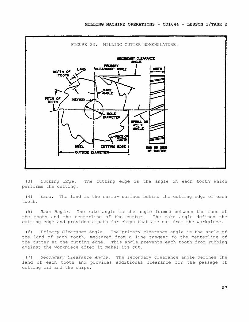
MILLING MACHINE OPERATIONS - OD1644 - LESSON 1/TASK 2
FIGURE 23. MILLING CUTTER NOMENCLATURE.
(3) Cutting Edge. The cutting edge is the angle on each tooth which performs the cutting.
(4) Land. The land is the narrow surface behind the cutting edge of each tooth.
(5) Rake Angle. The rake angle is the angle formed between the face of the tooth and the centerline of the cutter. The rake angle defines the cutting edge and provides a path for chips that are cut from the workpiece.
(6) Primary Clearance Angle. The primary clearance angle is the angle of the land of each tooth, measured from a line tangent to the centerline of the cutter at the cutting edge. This angle prevents each tooth from rubbing against the workpiece after it makes its cut.
(7) Secondary Clearance Angle. The secondary clearance angle defines the land of each tooth and provides additional clearance for the passage of cutting oil and the chips.
57
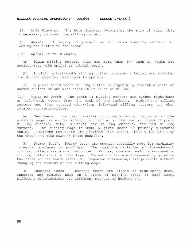
MILLING MACHINE OPERATIONS - OD1644 - LESSON 1/TASK 2
(8) Hole Diameter. The hole diameter determines the size of arbor that is necessary to mount the milling cutter.
(9) Keyway. A keyway is present on all arbor-mounting cutters for locking the cutter to the arbor.
(10) Spiral or Helix Angle.
(a) Plain milling cutters that are more than 3/4 inch in width are usually made with spiral or helical teeth.
(b) A plain spiral-tooth milling cutter produces a better and smoother finish, and requires less power to operate.
(c) A plain helix-tooth milling cutter is especially desirable where an uneven surface or one with holes in it is to be milled.
(11) Types of Teeth. The teeth of milling cutters are either right-hand or left-hand, viewed from the back of the machine. Right-hand milling cutters cut when rotated clockwise; left-hand milling cutters cut when rotated counterclockwise.
(a) Saw Teeth. Saw teeth similar to those shown in figure 23 on the previous page are either straight or helical in the smaller sizes of plain milling cutters, metal slitting saw milling cutters, and end milling cutters. The cutting edge is usually given about 5° primary clearance angle. Sometimes the teeth are provided with offset nicks which break up the chips and make coarser feeds possible.
(b) Formed Teeth. Formed teeth are usually specially made for machining irregular surfaces or profiles. The possible varieties of formed-tooth milling cutters are almost unlimited. Convex, concave, and corner-rounding milling cutters are of this type. Formed cutters are sharpened by grinding the faces of the teeth radially. Repeated sharpenings are possible without changing the contour of the cutting edge.
(c) Inserted Teeth. Inserted teeth are blades of high-speed steel inserted and rigidly held in a blank of machine steel or cast iron. Different manufacturers use different methods of holding the
58
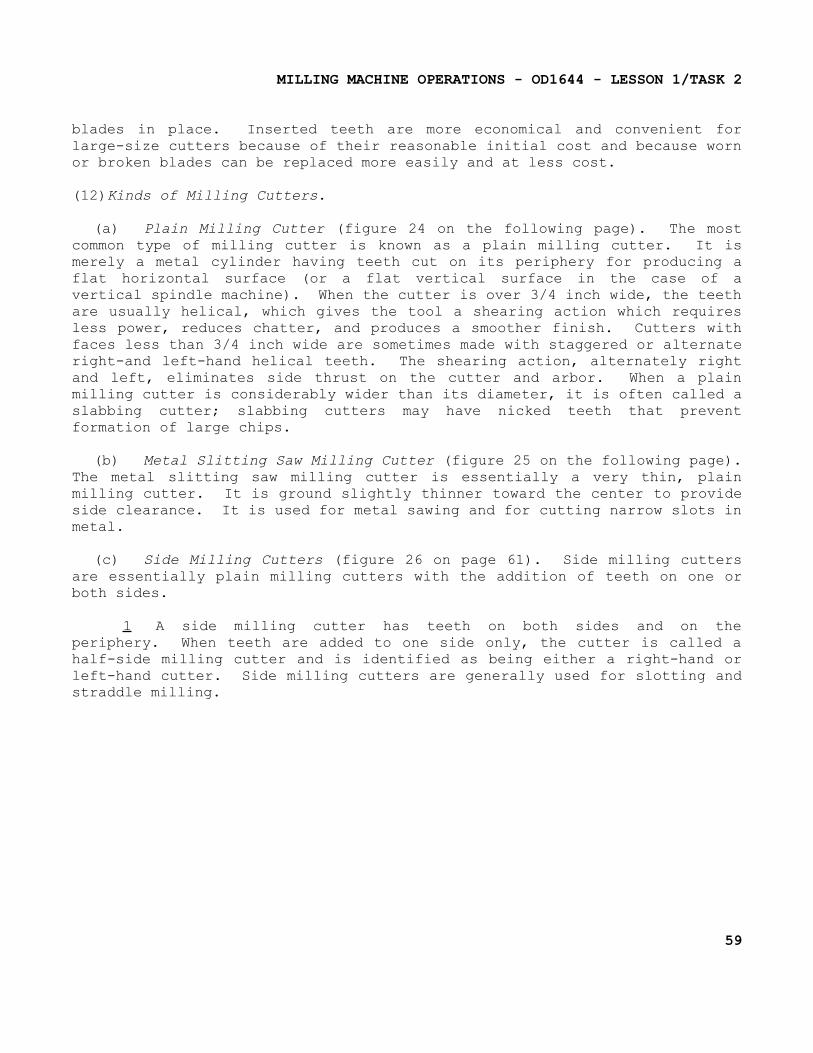
MILLING MACHINE OPERATIONS - OD1644 - LESSON 1/TASK 2
blades in place. Inserted teeth are more economical and convenient for large-size cutters because of their reasonable initial cost and because worn or broken blades can be replaced more easily and at less cost.
(12)Kinds of Milling Cutters.
(a) Plain Milling Cutter (figure 24 on the following page). The most common type of milling cutter is known as a plain milling cutter. It is merely a metal cylinder having teeth cut on its periphery for producing a flat horizontal surface (or a flat vertical surface in the case of a vertical spindle machine). When the cutter is over 3/4 inch wide, the teeth are usually helical, which gives the tool a shearing action which requires less power, reduces chatter, and produces a smoother finish. Cutters with faces less than 3/4 inch wide are sometimes made with staggered or alternate right-and left-hand helical teeth. The shearing action, alternately right and left, eliminates side thrust on the cutter and arbor. When a plain milling cutter is considerably wider than its diameter, it is often called a slabbing cutter; slabbing cutters may have nicked teeth that prevent formation of large chips.
(b) Metal Slitting Saw Milling Cutter (figure 25 on the following page). The metal slitting saw milling cutter is essentially a very thin, plain milling cutter. It is ground slightly thinner toward the center to provide side clearance. It is used for metal sawing and for cutting narrow slots in metal.
(c) Side Milling Cutters (figure 26 on page 61). Side milling cutters are essentially plain milling cutters with the addition of teeth on one or both sides.
1 A side milling cutter has teeth on both sides and on the periphery. When teeth are added to one side only, the cutter is called a half-side milling cutter and is identified as being either a right-hand or left-hand cutter. Side milling cutters are generally used for slotting and straddle milling.
59
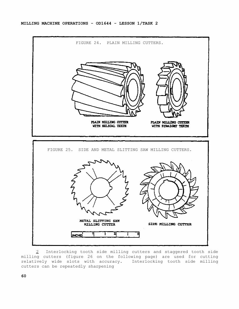
MILLING MACHINE OPERATIONS - OD1644 - LESSON 1/TASK 2
FIGURE 24. PLAIN MILLING CUTTERS.
FIGURE 25. SIDE AND METAL SLITTING SAW MILLING CUTTERS.
2 Interlocking tooth side milling cutters and staggered tooth side milling cutters (figure 26 on the following page) are used for cutting relatively wide slots with accuracy. Interlocking tooth side milling cutters can be repeatedly sharpening
60
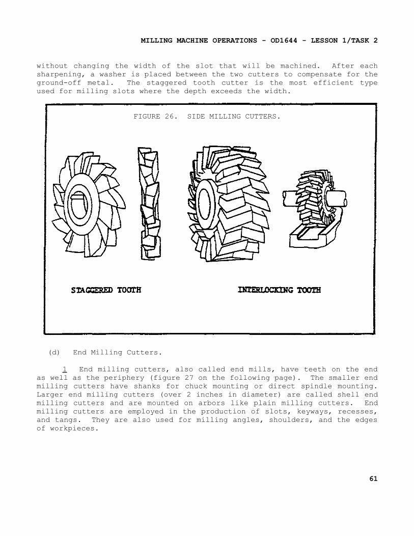
MILLING MACHINE OPERATIONS - OD1644 - LESSON 1/TASK 2
without changing the width of the slot that will be machined. After each sharpening, a washer is placed between the two cutters to compensate for the ground-off metal. The staggered tooth cutter is the most efficient type used for milling slots where the depth exceeds the width.
FIGURE 26. SIDE MILLING CUTTERS.
(d) End Milling Cutters.
1 End milling cutters, also called end mills, have teeth on the end as well as the periphery (figure 27 on the following page). The smaller end milling cutters have shanks for chuck mounting or direct spindle mounting. Larger end milling cutters (over 2 inches in diameter) are called shell end milling cutters and are mounted on arbors like plain milling cutters. End milling cutters are employed in the production of slots, keyways, recesses, and tangs. They are also used for milling angles, shoulders, and the edges of workpieces.
61
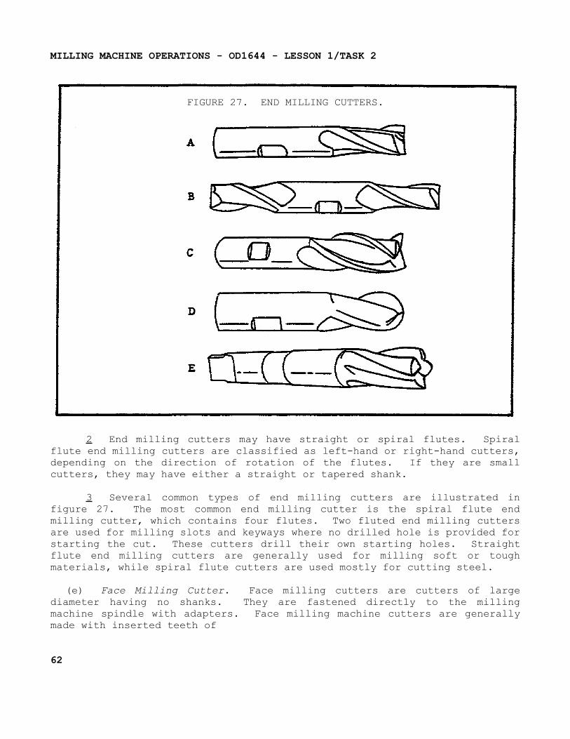
MILLING MACHINE OPERATIONS - OD1644 - LESSON 1/TASK 2
FIGURE 27. END MILLING CUTTERS.
2 End milling cutters may have straight or spiral flutes. Spiral flute end milling cutters are classified as left-hand or right-hand cutters, depending on the direction of rotation of the flutes. If they are small cutters, they may have either a straight or tapered shank.
3 Several common types of end milling cutters are illustrated in figure 27. The most common end milling cutter is the spiral flute end milling cutter, which contains four flutes. Two fluted end milling cutters are used for milling slots and keyways where no drilled hole is provided for starting the cut. These cutters drill their own starting holes. Straight flute end milling cutters are generally used for milling soft or tough materials, while spiral flute cutters are used mostly for cutting steel.
(e) Face Milling Cutter. Face milling cutters are cutters of large diameter having no shanks. They are fastened directly to the milling machine spindle with adapters. Face milling machine cutters are generally made with inserted teeth of
62
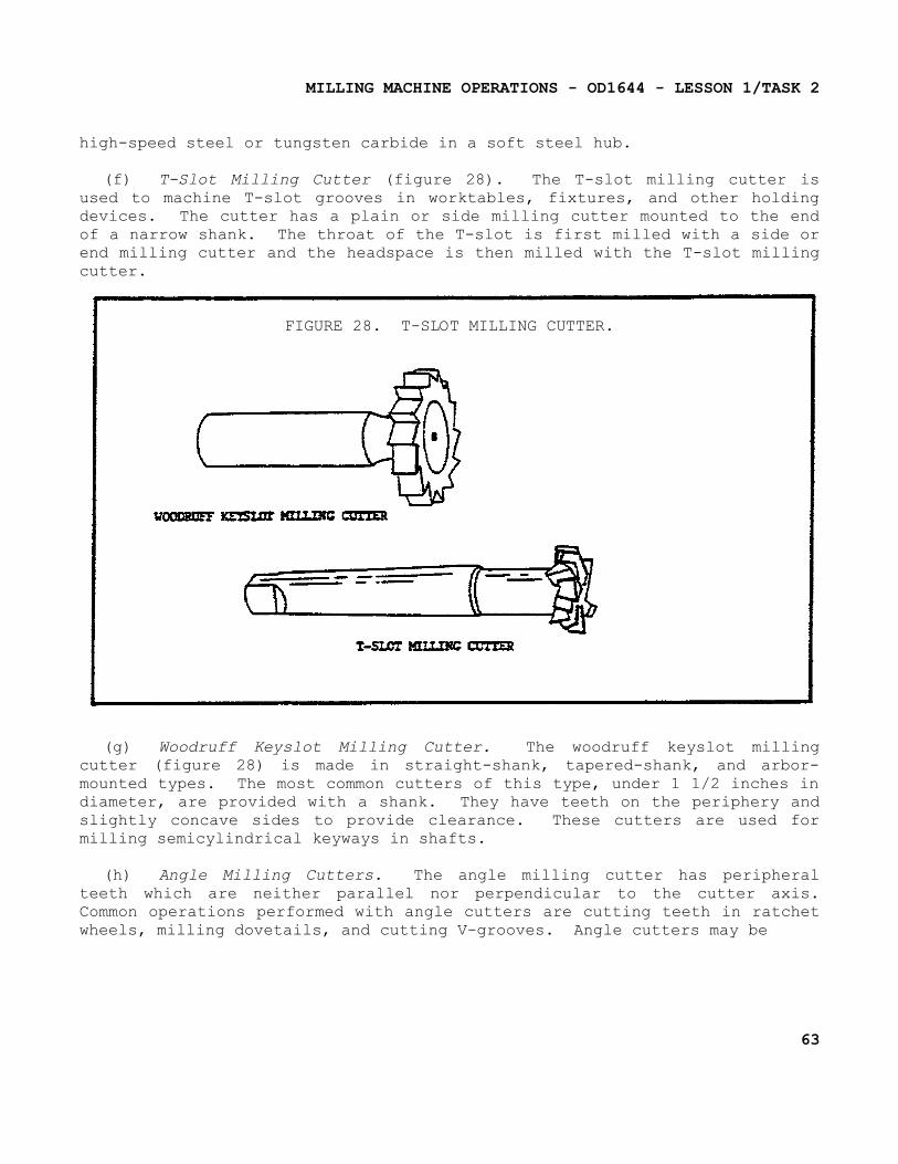
MILLING MACHINE OPERATIONS - OD1644 - LESSON 1/TASK 2
high-speed steel or tungsten carbide in a soft steel hub.
(f) T-Slot Milling Cutter (figure 28). The T-slot milling cutter is used to machine T-slot grooves in worktables, fixtures, and other holding devices. The cutter has a plain or side milling cutter mounted to the end of a narrow shank. The throat of the T-slot is first milled with a side or end milling cutter and the headspace is then milled with the T-slot milling cutter.
FIGURE 28. T-SLOT MILLING CUTTER.
(g) Woodruff Keyslot Milling Cutter. The woodruff keyslot milling cutter (figure 28) is made in straight-shank, tapered-shank, and arbor-mounted types. The most common cutters of this type, under 1 1/2 inches in diameter, are provided with a shank. They have teeth on the periphery and slightly concave sides to provide clearance. These cutters are used for milling semicylindrical keyways in shafts.
(h) Angle Milling Cutters. The angle milling cutter has peripheral teeth which are neither parallel nor perpendicular to the cutter axis. Common operations performed with angle cutters are cutting teeth in ratchet wheels, milling dovetails, and cutting V-grooves. Angle cutters may be
63
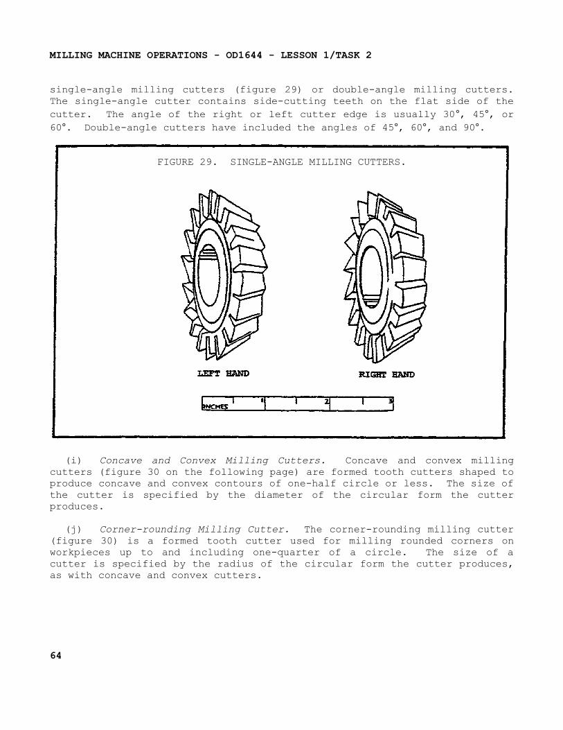
MILLING MACHINE OPERATIONS - OD1644 - LESSON 1/TASK 2
single-angle milling cutters (figure 29) or double-angle milling cutters. The single-angle cutter contains side-cutting teeth on the flat side of the cutter. The angle of the right or left cutter edge is usually 30°, 45°, or 60°. Double-angle cutters have included the angles of 45°, 60°, and 90°.
FIGURE 29. SINGLE-ANGLE MILLING CUTTERS.
(i) Concave and Convex Milling Cutters. Concave and convex milling cutters (figure 30 on the following page) are formed tooth cutters shaped to produce concave and convex contours of one-half circle or less. The size of the cutter is specified by the diameter of the circular form the cutter produces.
(j) Corner-rounding Milling Cutter. The corner-rounding milling cutter (figure 30) is a formed tooth cutter used for milling rounded corners on workpieces up to and including one-quarter of a circle. The size of a cutter is specified by the radius of the circular form the cutter produces, as with concave and convex cutters.
64
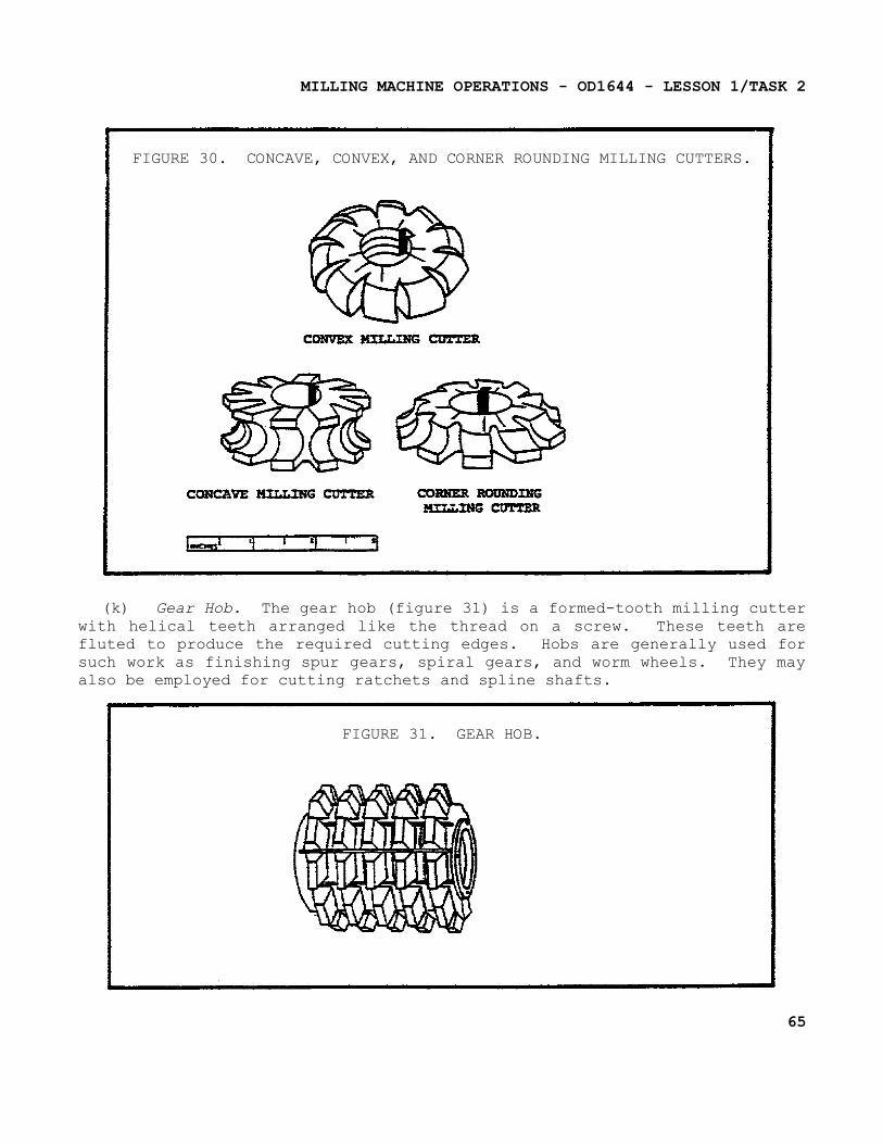
MILLING MACHINE OPERATIONS - OD1644 - LESSON 1/TASK 2
FIGURE 30. CONCAVE, CONVEX, AND CORNER ROUNDING MILLING CUTTERS.
(k) Gear Hob. The gear hob (figure 31) is a formed-tooth milling cutter with helical teeth arranged like the thread on a screw. These teeth are fluted to produce the required cutting edges. Hobs are generally used for such work as finishing spur gears, spiral gears, and worm wheels. They may also be employed for cutting ratchets and spline shafts.
FIGURE 31. GEAR HOB.
65
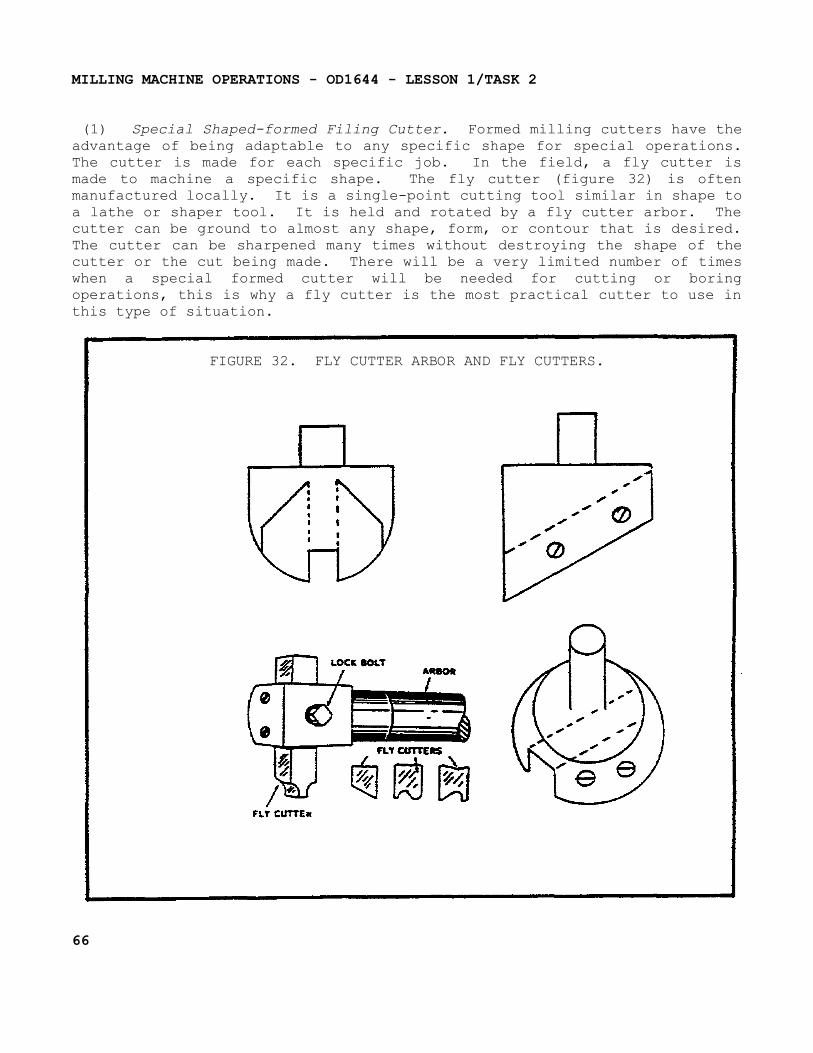
MILLING MACHINE OPERATIONS - OD1644 - LESSON 1/TASK 2
(1) Special Shaped-formed Filing Cutter. Formed milling cutters have the advantage of being adaptable to any specific shape for special operations. The cutter is made for each specific job. In the field, a fly cutter is made to machine a specific shape. The fly cutter (figure 32) is often manufactured locally. It is a single-point cutting tool similar in shape to a lathe or shaper tool. It is held and rotated by a fly cutter arbor. The cutter can be ground to almost any shape, form, or contour that is desired. The cutter can be sharpened many times without destroying the shape of the cutter or the cut being made. There will be a very limited number of times when a special formed cutter will be needed for cutting or boring operations, this is why a fly cutter is the most practical cutter to use in this type of situation.
FIGURE 32. FLY CUTTER ARBOR AND FLY CUTTERS.
66
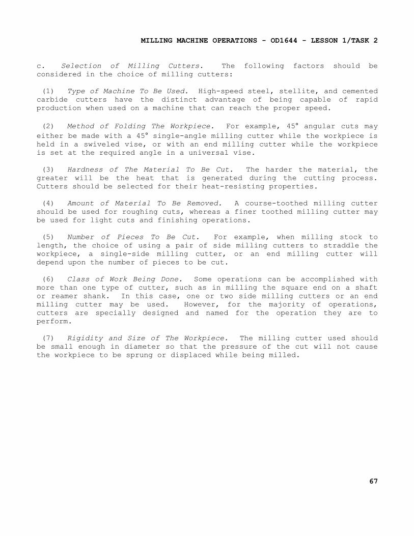
MILLING MACHINE OPERATIONS - OD1644 - LESSON 1/TASK 2
c. Selection of Milling Cutters. The following factors should be considered in the choice of milling cutters:
(1) Type of Machine To Be Used. High-speed steel, stellite, and cemented carbide cutters have the distinct advantage of being capable of rapid production when used on a machine that can reach the proper speed.
(2) Method of Folding The Workpiece. For example, 45° angular cuts may either be made with a 45° single-angle milling cutter while the workpiece is held in a swiveled vise, or with an end milling cutter while the workpiece is set at the required angle in a universal vise.
(3) Hardness of The Material To Be Cut. The harder the material, the greater will be the heat that is generated during the cutting process. Cutters should be selected for their heat-resisting properties.
(4) Amount of Material To Be Removed. A course-toothed milling cutter should be used for roughing cuts, whereas a finer toothed milling cutter may be used for light cuts and finishing operations.
(5) Number of Pieces To Be Cut. For example, when milling stock to length, the choice of using a pair of side milling cutters to straddle the workpiece, a single-side milling cutter, or an end milling cutter will depend upon the number of pieces to be cut.
(6) Class of Work Being Done. Some operations can be accomplished with more than one type of cutter, such as in milling the square end on a shaft or reamer shank. In this case, one or two side milling cutters or an end milling cutter may be used. However, for the majority of operations, cutters are specially designed and named for the operation they are to perform.
(7) Rigidity and Size of The Workpiece. The milling cutter used should be small enough in diameter so that the pressure of the cut will not cause the workpiece to be sprung or displaced while being milled.
67
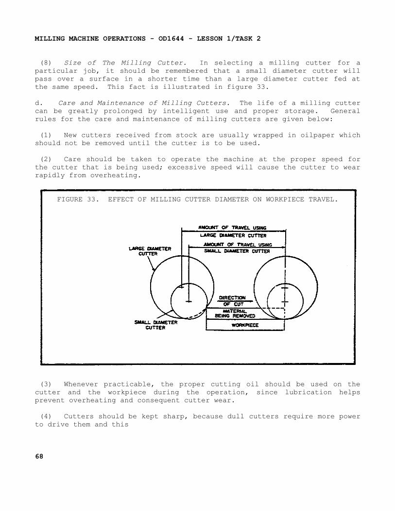
MILLING MACHINE OPERATIONS - OD1644 - LESSON 1/TASK 2
(8) Size of The Milling Cutter. In selecting a milling cutter for a particular job, it should be remembered that a small diameter cutter will pass over a surface in a shorter time than a large diameter cutter fed at the same speed. This fact is illustrated in figure 33.
d. Care and Maintenance of Milling Cutters. The life of a milling cutter can be greatly prolonged by intelligent use and proper storage. General rules for the care and maintenance of milling cutters are given below:
(1) New cutters received from stock are usually wrapped in oilpaper which should not be removed until the cutter is to be used.
(2) Care should be taken to operate the machine at the proper speed for the cutter that is being used; excessive speed will cause the cutter to wear rapidly from overheating.
FIGURE 33. EFFECT OF MILLING CUTTER DIAMETER ON WORKPIECE TRAVEL.
(3) Whenever practicable, the proper cutting oil should be used on the cutter and the workpiece during the operation, since lubrication helps prevent overheating and consequent cutter wear.
(4) Cutters should be kept sharp, because dull cutters require more power to drive them and this
68

MILLING MACHINE OPERATIONS - OD1644 - LESSON 1/TASK 2
power, being transformed into heat, softens the cutting edges. Dull cutters should be marked as such and set aside for grinding.
(5) A cutter should never be operated backward because, due to the clearance angle, the cutter will rub, producing a great deal of frictional heat. Operating the cutter backward may result in cutter breakage.
(6) Care should be taken to prevent the putter from striking the hard jaws of the vise, chuck, clamping bolts, or nuts.
(7) A milling cutter should be thoroughly cleaned and lightly coated with oil before storing.
(8) Cutters should be placed in drawers or bins in such a manner that their cutting edges will not strike each other. Small cutters that have a hole in the center should be hung on hooks or pegs, large cutters should be set on end. Tapered and straight shank cutters may be placed in separate drawers, bins, or racks provided with suitable sized holes to receive the shanks.
3. Conclusion
Milling cutters play an important role in performing milling machine operations. Knowing which cutter to select and use for a specific operation, will at times, determine the overall quality of the final product. The knowledge gained in this task on milling cutters will assist you in determining the type of cutter(s) to employ for a specific operation, to include the nomenclature, selection, use and care of milling cutters when tasked to perform milling machine operations.
69
MILLING MACHINE OPERATIONS - OD1644 - LESSON 1/PE 1
PRACTICAL EXERCISE
1. Instructions
On a plain piece of paper, respond to the requirements listed below.
2. Requirement
Successful completion of this exercise provides indication of success in the subcourse. Check your answers against those provided on the answer page following questions.
a. How are knee-type milling machines characterized?
b. What is the basic difference between a universal horizontal and a plain horizontal milling machine?
c. Which component holds and drives the various cutting tools on the knee-type milling machine?
d. Which component on the ram-type milling machine aligns the outer end of the arbor with the spindle?
e. How are milling machines classified or identified?
f. What is the most common means of fastening the arbor in the milling machine spindle?
g. What is another name for the indexing head?
h. When clamping workpieces to the table, what is used to protect the surfaces of the workpiece?
i. Workpieces mounted between centers are prevented from backlash by what type device?
j. What is the ratio on a standard indexing head?
k. Direct indexing plates usually have how many holes?
l. Face milling operations require the flat surface to be machined at what angles to the axis to the cutter?
70
MILLING MACHINE OPERATIONS - OD1644 - LESSON 1/PE 1
m. What determines the cutting speed for a milling operation?
n. What is angular milling?
o. Which teeth do most of the cutting during a face milling operation?
p. What is the required time allocated for proper gib adjustment on a new milling machine?
q. When making knee gib adjustments with a dial indicator, the deflection should not be more than how many thousandths of an inch?
r. When the gibs are adjusted too tightly, what is the end result?
s. Which type milling cutter requires less power to operate and produces a smoother finish?
t. How do milling cutters receive their names?
u. Pitch on a milling cutter refers to the___________.
v. What is the most common type of milling cutter?
w. Which type cutters are used for cutting relatively wide slots with accuracy?
71
MILLING MACHINE OPERATIONS - OD1644 - LESSON 1/PE 1
LESSON 1. PRACTICAL EXERCISE - ANSWERS
Requirement
a. The knee-type milling machines are characterized by a vertical adjustable worktable resting on a saddle that is supported by a knee.
b. The adjustment of the worktable and various attachments for performing a variety of special milling operations and the universal milling machine is of the Ram-type.
c. The spindle
d. Arbor support
e. Size, horsepower, model, and type
f. Draw-in bar
g. Dividing head or gear cutting attachment
h. They should be protected with pieces of soft metal.
i. Dog and setscrew
j. 40 turns of the index crank revolves the spindle one complete turn (40 to 1 ratio).
k. 24 holes
l. Right angles
m. The type of materials being cut and the size of the cutter being used
n. Angular milling is milling flat surfaces that are neither parallel nor perpendicular to the axis of the milling cutter.
o. The teeth on the periphery of the cutter
p. After 40 hours
q. 0.0003 inch
r. Severe wear and strain on the milling machine
s. Plain spiral-tooth cutter
72
MILLING MACHINE OPERATIONS - OD1644 - LESSON 1/PE 1
t. Usually from the operation in which they perform
u. Angular distance between like parts on the adjacent teeth
v. Plain milling cutter
w. Interlocking tooth side milling cutters and or staggered tooth side milling cutters.
73

MILLING MACHINE OPERATIONS - OD1644 - REFERENCES
REFERENCES
74
MILLING MACHINE OPERATIONS - OD1644 - REFERENCES
REFERENCES
The following documents were used as resource materials in developing this subcourse:
DA Pam 738-750TM 9-3417-213-10TM 9-3417-213-14&PFM 9-24
75
Related Documents