CONFIDENTIAL 1 Presented by: John Coonrod Microwave and Millimeter-Wave High Frequency Circuit Material Performance (up to 110 GHz)

Microwave and Millimeter-Wave High Frequency Circuit Material Performance (Up to 110 GHz)
Dec 06, 2015
Rogers materials
Welcome message from author
This document is posted to help you gain knowledge. Please leave a comment to let me know what you think about it! Share it to your friends and learn new things together.
Transcript

CONFIDENTIAL 1
Presented by: John Coonrod
Microwave and Millimeter-Wave High Frequency Circuit Material Performance (up to 110 GHz)
CONFIDENTIAL 2
Agenda:
• Overview of frequency dependent dielectric behavior
• Dissecting insertion loss
• Copper surface roughness influences
• Comparing insertion loss of different designs and plated finishes
CONFIDENTIAL 3
Overview of frequency dependent dielectric behavior
Microwave and Millimeter-Wave High Frequency Circuit Material Performance (up to 110 GHz)
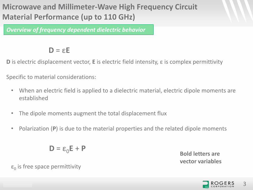
D = εE
D is electric displacement vector, E is electric field intensity, ε is complex permittivity
Specific to material considerations:
• When an electric field is applied to a dielectric material, electric dipole moments are established
• The dipole moments augment the total displacement flux
• Polarization (P) is due to the material properties and the related dipole moments
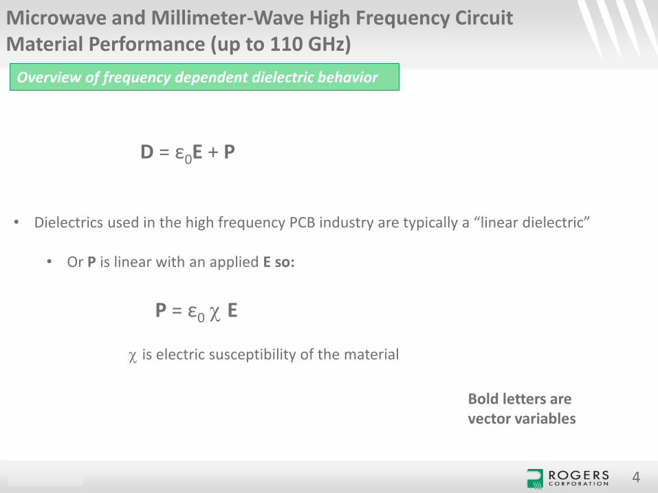
D = ε0E + P
ε0 is free space permittivity
Bold letters are vector variables
CONFIDENTIAL 4
Overview of frequency dependent dielectric behavior
Microwave and Millimeter-Wave High Frequency Circuit Material Performance (up to 110 GHz)
c is electric susceptibility of the material
• Dielectrics used in the high frequency PCB industry are typically a “linear dielectric”
• Or P is linear with an applied E so:
P = ε0 c E
D = ε0E + P
Bold letters are vector variables
CONFIDENTIAL 5
Overview of frequency dependent dielectric behavior
Microwave and Millimeter-Wave High Frequency Circuit Material Performance (up to 110 GHz)
Bold letters are vector variables
D = ε0E + P = ε0 (1+ c) E = εE
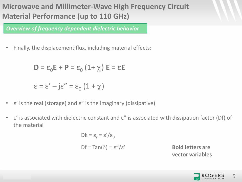
• Finally, the displacement flux, including material effects:
ε = ε’ – jε” = ε0 (1 + c)
• ε’ is the real (storage) and ε” is the imaginary (dissipative)
• ε’ is associated with dielectric constant and ε” is associated with dissipation factor (Df) of the material
Dk = εr = ε’/ε0
Df = Tan() = ε”/ε’
CONFIDENTIAL 6
Overview of frequency dependent dielectric behavior
Microwave and Millimeter-Wave High Frequency Circuit Material Performance (up to 110 GHz)
• Dipole displacement contributes to the Dk (εr)
• Molecular friction due to dipole rotation contributes to tan() or Df
• Depending on material properties, from about 10 MHz to 300 GHz, most interaction between electric fields and substrate is due to displacement and rotation of the dipoles
CONFIDENTIAL 7
Overview of frequency dependent dielectric behavior
Microwave and Millimeter-Wave High Frequency Circuit Material Performance (up to 110 GHz)
• Dispersion is how much the Dk will change with a change in frequency
• Dipole moment relaxation is another issue which contributes to dispersion
• At low radio frequencies the dipole relaxation has little effect on Dk dispersion
• At microwave frequencies dipole relaxation has significant effect on dispersion
CONFIDENTIAL
Overview of frequency dependent dielectric behavior
Microwave and Millimeter-Wave High Frequency Circuit Material Performance (up to 110 GHz)
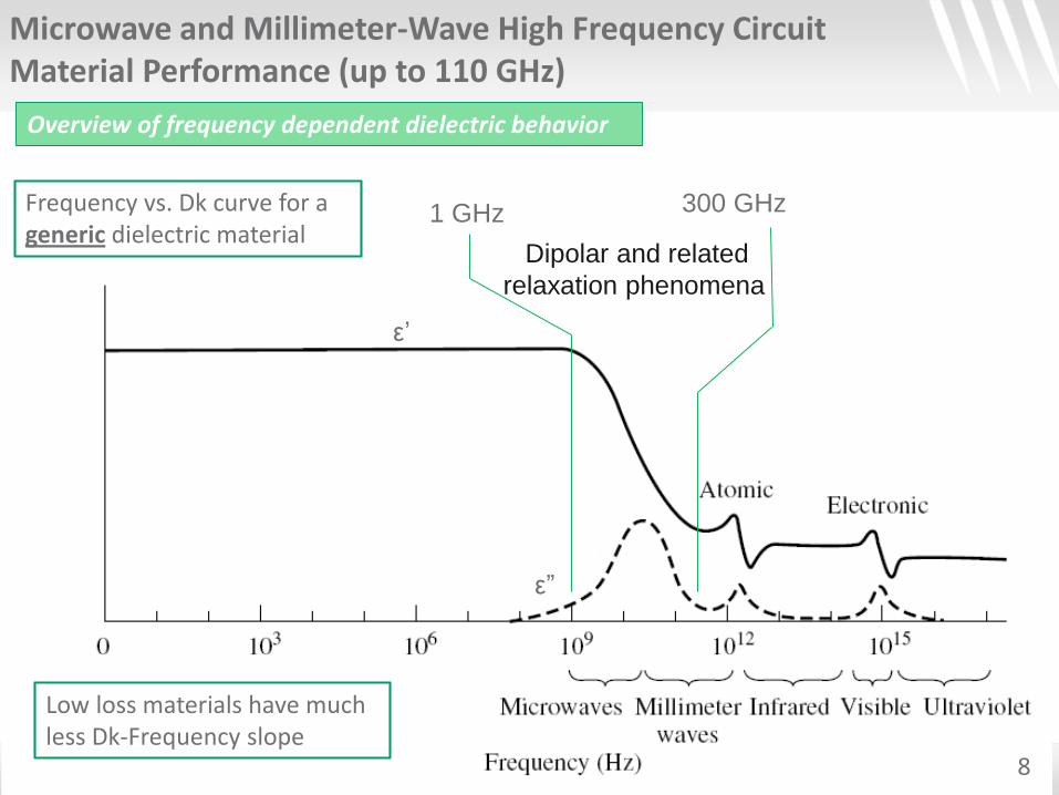
ε’
1 GHz 300 GHzFrequency vs. Dk curve for a generic dielectric material
Dipolar and related
relaxation phenomena
8
Low loss materials have much less Dk-Frequency slope
ε”
CONFIDENTIAL
Overview of frequency dependent dielectric behavior
Microwave and Millimeter-Wave High Frequency Circuit Material Performance (up to 110 GHz)
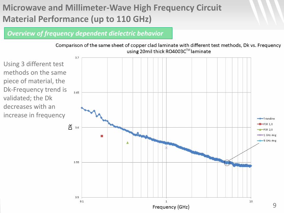
Using 3 different test methods on the same piece of material, the Dk-Frequency trend is validated; the Dkdecreases with an increase in frequency
9
CONFIDENTIAL
Microwave and Millimeter-Wave High Frequency Circuit Material Performance (up to 110 GHz)
10
Dissecting insertion loss
CONFIDENTIAL
Dissecting insertion loss
Microwave and Millimeter-Wave High Frequency Circuit Material Performance (up to 110 GHz)
11
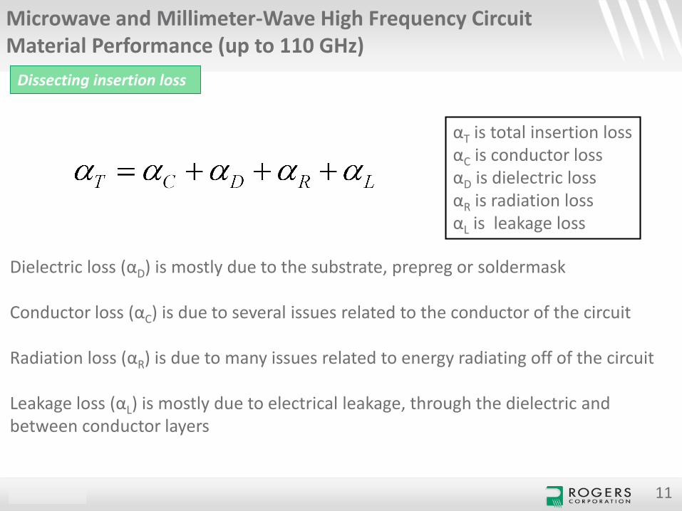
αT is total insertion lossαC is conductor lossαD is dielectric lossαR is radiation lossαL is leakage loss
Dielectric loss (αD) is mostly due to the substrate, prepreg or soldermask
Conductor loss (αC) is due to several issues related to the conductor of the circuit
Radiation loss (αR) is due to many issues related to energy radiating off of the circuit
Leakage loss (αL) is mostly due to electrical leakage, through the dielectric and between conductor layers
CONFIDENTIAL
Microwave and Millimeter-Wave High Frequency Circuit Material Performance (up to 110 GHz)
12
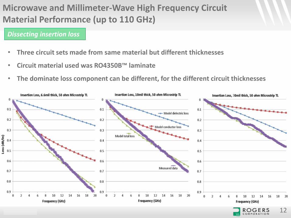
• Three circuit sets made from same material but different thicknesses
• Circuit material used was RO4350B™ laminate
• The dominate loss component can be different, for the different circuit thicknesses
Dissecting insertion loss
CONFIDENTIAL
Microwave and Millimeter-Wave High Frequency Circuit Material Performance (up to 110 GHz)
13
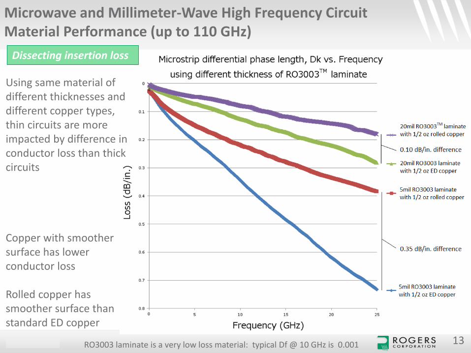
Dissecting insertion loss
Using same material of different thicknesses and different copper types, thin circuits are more impacted by difference in conductor loss than thick circuits
Copper with smoother surface has lower conductor loss
Rolled copper has smoother surface than standard ED copper
RO3003 laminate is a very low loss material: typical Df @ 10 GHz is 0.001
CONFIDENTIAL
Microwave and Millimeter-Wave High Frequency Circuit Material Performance (up to 110 GHz)
14
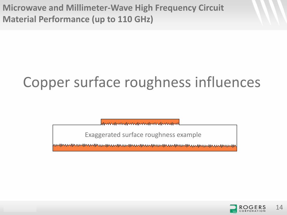
Copper surface roughness influences
Exaggerated surface roughness example
CONFIDENTIAL
Microwave and Millimeter-Wave High Frequency Circuit Material Performance (up to 110 GHz)
15
Copper surface roughness influences
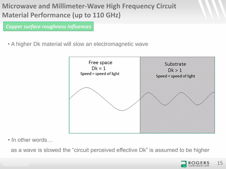
• A higher Dk material will slow an electromagnetic wave
• In other words…
as a wave is slowed the “circuit perceived effective Dk” is assumed to be higher
CONFIDENTIAL
Microwave and Millimeter-Wave High Frequency Circuit Material Performance (up to 110 GHz)
16
Copper surface roughness influences
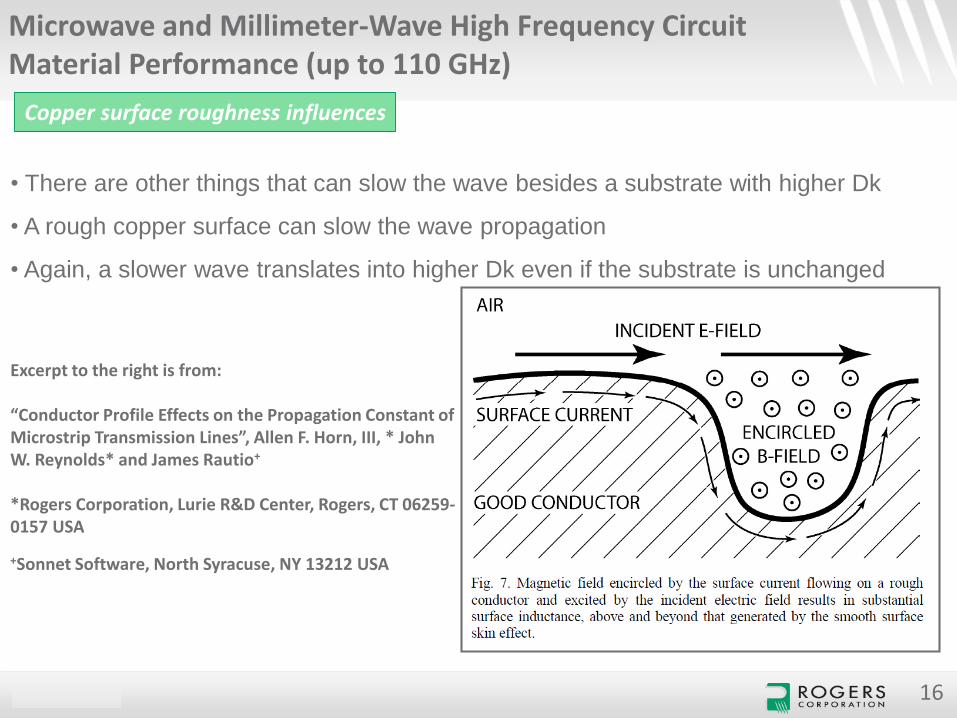
• There are other things that can slow the wave besides a substrate with higher Dk
• A rough copper surface can slow the wave propagation
• Again, a slower wave translates into higher Dk even if the substrate is unchanged
Excerpt to the right is from:
“Conductor Profile Effects on the Propagation Constant of Microstrip Transmission Lines”, Allen F. Horn, III, * John W. Reynolds* and James Rautio+
*Rogers Corporation, Lurie R&D Center, Rogers, CT 06259-0157 USA
+Sonnet Software, North Syracuse, NY 13212 USA
CONFIDENTIAL
Microwave and Millimeter-Wave High Frequency Circuit Material Performance (up to 110 GHz)
17
Copper surface roughness influences
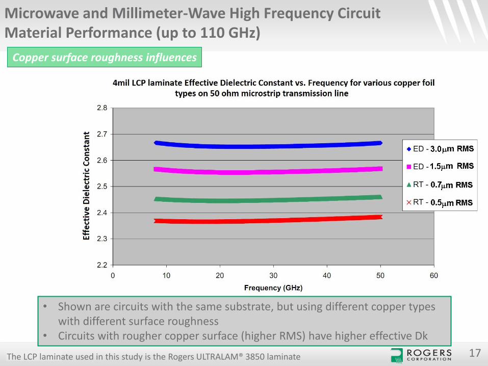
• Shown are circuits with the same substrate, but using different copper types with different surface roughness
• Circuits with rougher copper surface (higher RMS) have higher effective Dk
The LCP laminate used in this study is the Rogers ULTRALAM® 3850 laminate
CONFIDENTIAL
Microwave and Millimeter-Wave High Frequency Circuit Material Performance (up to 110 GHz)
18
Copper surface roughness influences
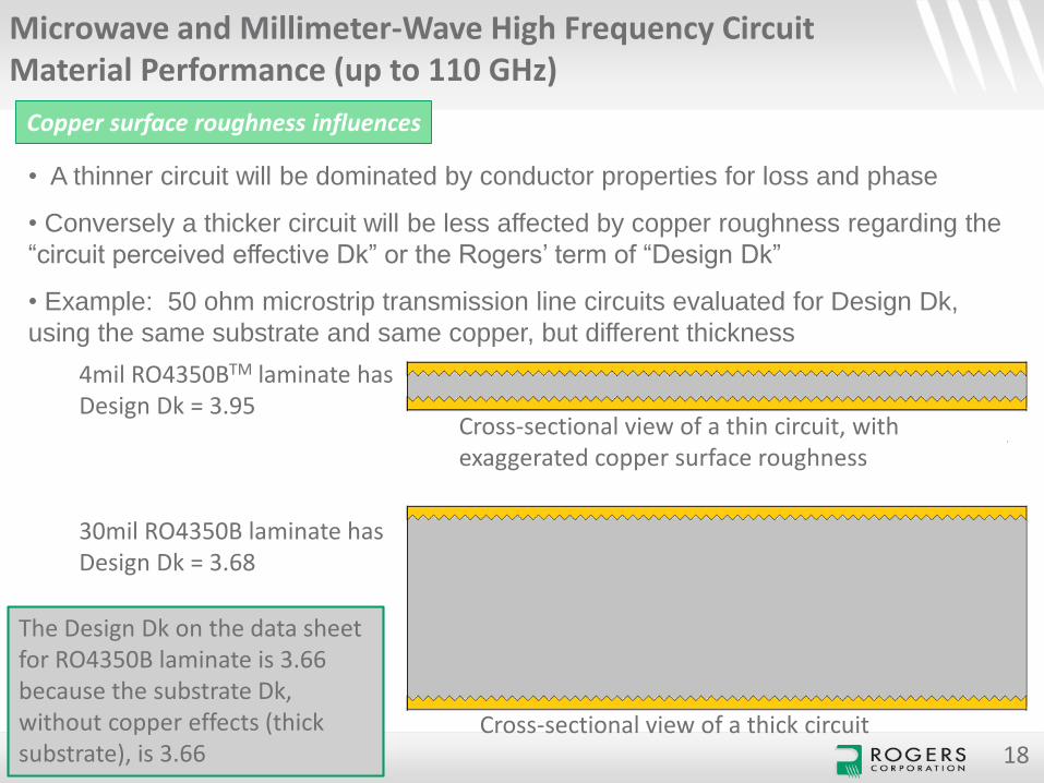
• A thinner circuit will be dominated by conductor properties for loss and phase
• Conversely a thicker circuit will be less affected by copper roughness regarding the
“circuit perceived effective Dk” or the Rogers’ term of “Design Dk”
• Example: 50 ohm microstrip transmission line circuits evaluated for Design Dk,
using the same substrate and same copper, but different thickness
Cross-sectional view of a thin circuit, with exaggerated copper surface roughness
Cross-sectional view of a thick circuit
4mil RO4350BTM laminate has Design Dk = 3.95
30mil RO4350B laminate has Design Dk = 3.68
The Design Dk on the data sheet for RO4350B laminate is 3.66 because the substrate Dk, without copper effects (thick substrate), is 3.66
CONFIDENTIAL
Microwave and Millimeter-Wave High Frequency Circuit Material Performance (up to 110 GHz)
19
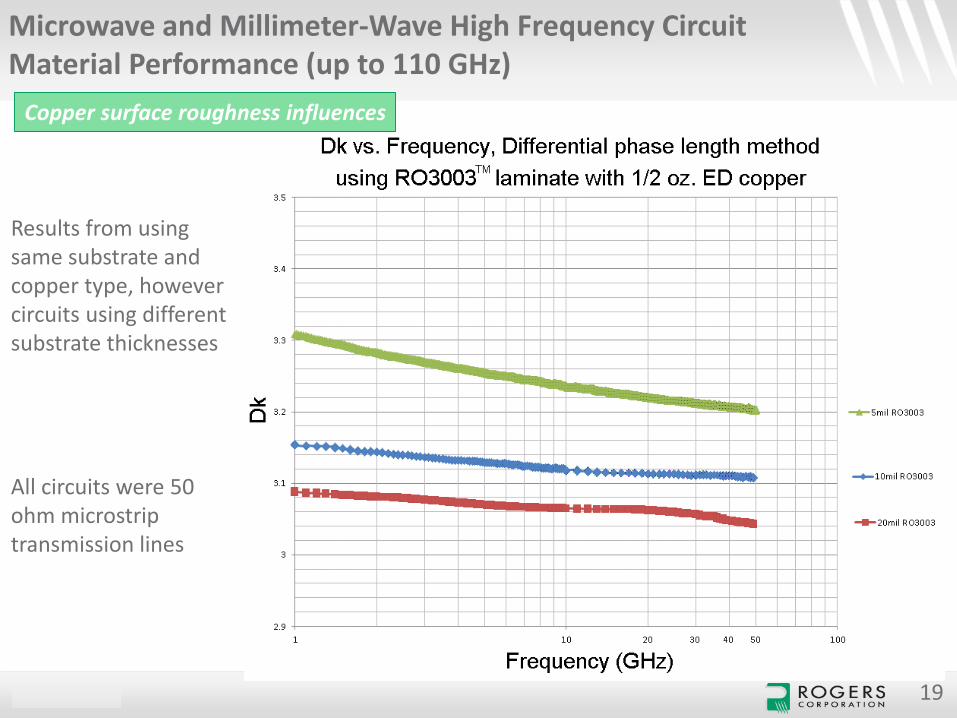
Results from using same substrate and copper type, however circuits using different substrate thicknesses
All circuits were 50 ohm microstrip transmission lines
Copper surface roughness influences
CONFIDENTIAL 20
Microwave and Millimeter-Wave High Frequency Circuit Material Performance (up to 110 GHz)
Copper surface roughness influences
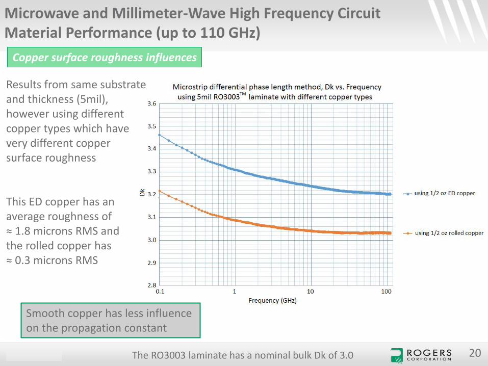
Results from same substrate and thickness (5mil), however using different copper types which have very different copper surface roughness
This ED copper has an average roughness of ≈ 1.8 microns RMS andthe rolled copper has ≈ 0.3 microns RMS
The RO3003 laminate has a nominal bulk Dk of 3.0
Smooth copper has less influence on the propagation constant
CONFIDENTIAL 21
Microwave and Millimeter-Wave High Frequency Circuit Material Performance (up to 110 GHz)
Comparing insertion loss of different designs and plated finishes
CONFIDENTIAL 22
Microwave and Millimeter-Wave High Frequency Circuit Material Performance (up to 110 GHz)
Comparing insertion loss of different designs and plated finish
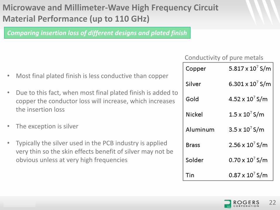
• Most final plated finish is less conductive than copper
• Due to this fact, when most final plated finish is added to copper the conductor loss will increase, which increases the insertion loss
• The exception is silver
• Typically the silver used in the PCB industry is applied very thin so the skin effects benefit of silver may not be obvious unless at very high frequencies
Conductivity of pure metals
CONFIDENTIAL 23
Microwave and Millimeter-Wave High Frequency Circuit Material Performance (up to 110 GHz)
Comparing insertion loss of different designs and plated finish
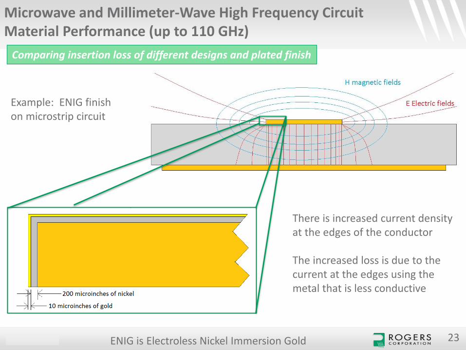
There is increased current density at the edges of the conductor
The increased loss is due to the current at the edges using the metal that is less conductive
Example: ENIG finish on microstrip circuit
ENIG is Electroless Nickel Immersion Gold
CONFIDENTIAL
Microwave and Millimeter-Wave High Frequency Circuit Material Performance (up to 110 GHz)
Comparing insertion loss of different designs and plated finish
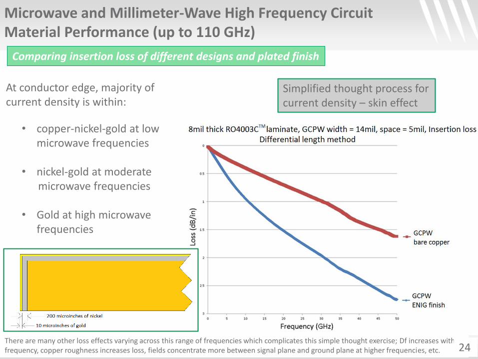
• copper-nickel-gold at low microwave frequencies
• nickel-gold at moderate microwave frequencies
• Gold at high microwave frequencies
Simplified thought process for current density – skin effect
At conductor edge, majority of current density is within:
There are many other loss effects varying across this range of frequencies which complicates this simple thought exercise; Df increases with frequency, copper roughness increases loss, fields concentrate more between signal plane and ground plane at higher frequencies, etc. 24
CONFIDENTIAL 25
Microwave and Millimeter-Wave High Frequency Circuit Material Performance (up to 110 GHz)
Comparing insertion loss of different designs and plated finish
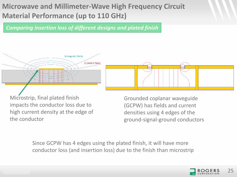
Microstrip, final plated finish impacts the conductor loss due to high current density at the edge of the conductor
Grounded coplanar waveguide (GCPW) has fields and current densities using 4 edges of the ground-signal-ground conductors
Since GCPW has 4 edges using the plated finish, it will have more conductor loss (and insertion loss) due to the finish than microstrip
CONFIDENTIAL 26
Microwave and Millimeter-Wave High Frequency Circuit Material Performance (up to 110 GHz)
Comparing insertion loss of different designs and plated finish
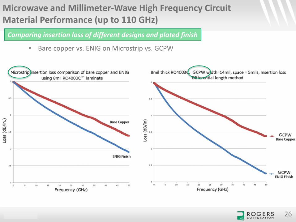
• Bare copper vs. ENIG on Microstrip vs. GCPW
CONFIDENTIAL 27
Microwave and Millimeter-Wave High Frequency Circuit Material Performance (up to 110 GHz)
Comparing insertion loss of different designs and plated finish
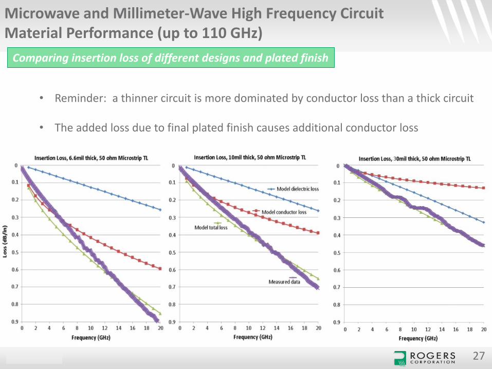
• Reminder: a thinner circuit is more dominated by conductor loss than a thick circuit
• The added loss due to final plated finish causes additional conductor loss
CONFIDENTIAL 28
Microwave and Millimeter-Wave High Frequency Circuit Material Performance (up to 110 GHz)
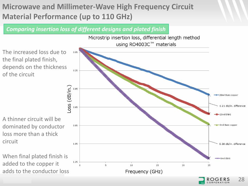
The increased loss due to the final plated finish, depends on the thickness of the circuit
A thinner circuit will be dominated by conductor loss more than a thick circuit
When final plated finish is added to the copper it adds to the conductor loss
Comparing insertion loss of different designs and plated finish
CONFIDENTIAL 29
Microwave and Millimeter-Wave High Frequency Circuit Material Performance (up to 110 GHz)
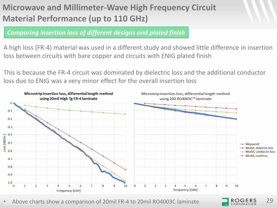
A high loss (FR-4) material was used in a different study and showed little difference in insertion loss between circuits with bare copper and circuits with ENIG plated finish
This is because the FR-4 circuit was dominated by dielectric loss and the additional conductor loss due to ENIG was a very minor effect for the overall insertion loss
Comparing insertion loss of different designs and plated finish
• Above charts show a comparison of 20mil FR-4 to 20mil RO4003C laminate
CONFIDENTIAL
Microwave and Millimeter-Wave High Frequency Circuit Material Performance (up to 110 GHz)
Comparing insertion loss of different designs and plated finish
30
• The following slides are insertion loss curves comparing plated finish over very wideband
• All circuits were 50 ohm microstrip transmission line circuits
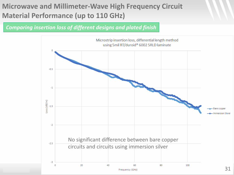
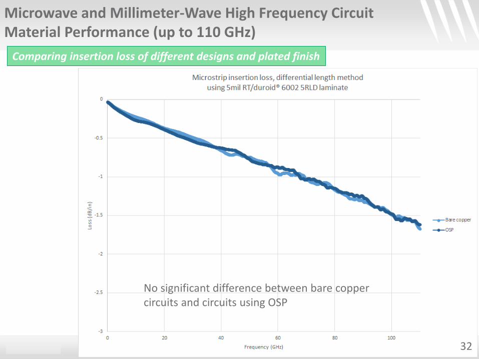
• All circuits used a thin, very low loss thin laminate: 5mil RT/duroid® 6002 with rolled copper
• Basic material electrical properties when tested at 10 GHz is:
• Dk = 2.94
• Df = 0.0012
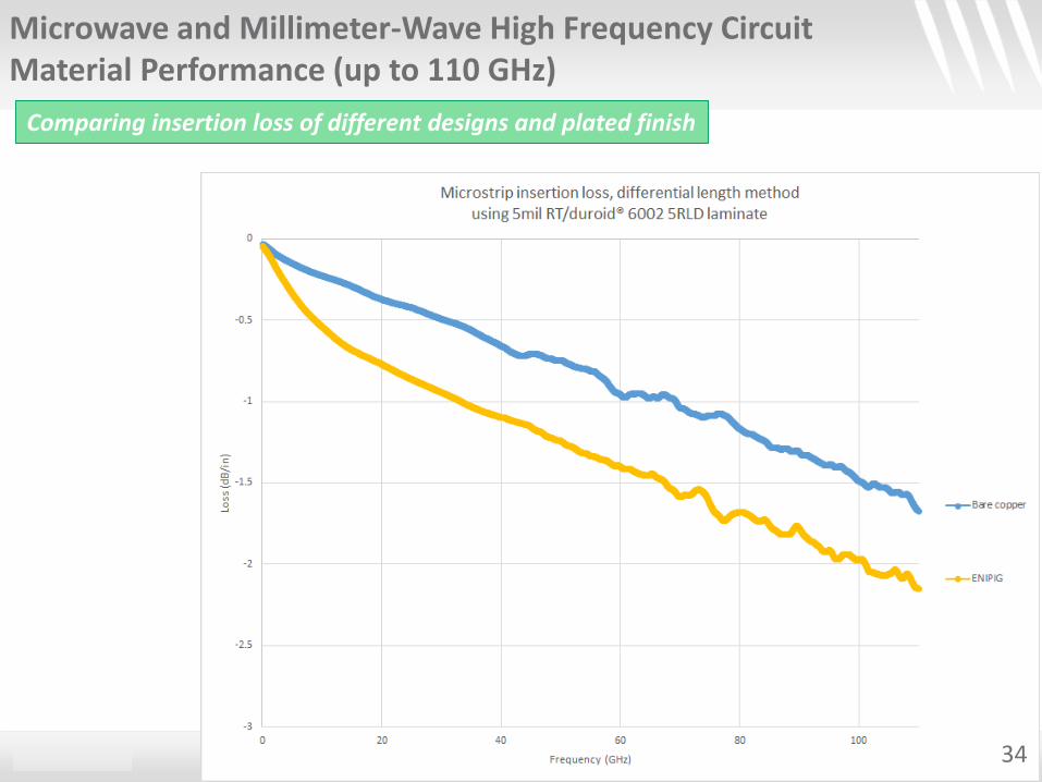
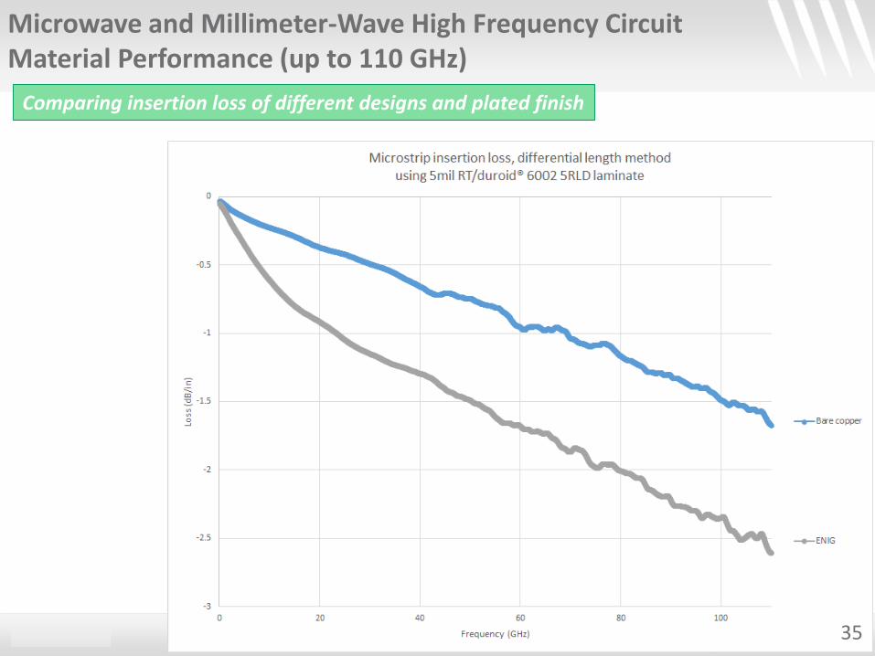
• The simple loss trend compared to copper, from least to most loss, is the following:• Immersion silver (no significant difference)• OSP• Immersion Tin• ENIPEG• ENIG
CONFIDENTIAL
Microwave and Millimeter-Wave High Frequency Circuit Material Performance (up to 110 GHz)
Comparing insertion loss of different designs and plated finish
No significant difference between bare copper circuits and circuits using immersion silver
31
CONFIDENTIAL
Microwave and Millimeter-Wave High Frequency Circuit Material Performance (up to 110 GHz)
Comparing insertion loss of different designs and plated finish
No significant difference between bare copper circuits and circuits using OSP
32
CONFIDENTIAL
Microwave and Millimeter-Wave High Frequency Circuit Material Performance (up to 110 GHz)
Comparing insertion loss of different designs and plated finish
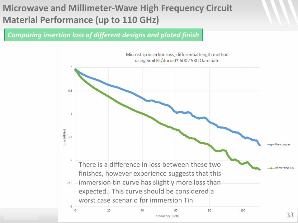
There is a difference in loss between these two finishes, however experience suggests that this immersion tin curve has slightly more loss than expected. This curve should be considered a worst case scenario for immersion Tin
33
CONFIDENTIAL
Microwave and Millimeter-Wave High Frequency Circuit Material Performance (up to 110 GHz)
Comparing insertion loss of different designs and plated finish
34
CONFIDENTIAL
Microwave and Millimeter-Wave High Frequency Circuit Material Performance (up to 110 GHz)
Comparing insertion loss of different designs and plated finish
35
CONFIDENTIAL
Microwave and Millimeter-Wave High Frequency Circuit Material Performance (up to 110 GHz)
Comparing insertion loss of different designs and plated finish
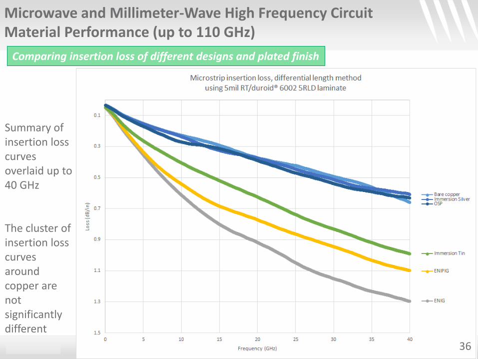
Summary of insertion loss curves overlaid up to 40 GHz
The cluster of insertion loss curves around copper are not significantly different
36
CONFIDENTIAL 37
Thank You to Enthone for their support on the final plating finish studies
Microwave and Millimeter-Wave High Frequency Circuit Material Performance (up to 110 GHz)

CONFIDENTIAL
Become a Member of Rogers Technology Support Hub for Additional Technical Tools & Information. Sign up to Receive Email Updates to be Kept up to Date on Rogers’ Recently Released Products.
www.rogerscorp.com/techub
Microwave Impedance Calculator
Electrical & Thermal Calculators
Engineering Support
Technical Papers
RO3003, RO4003C, RO4350B, ULTRALAM, RT/duroid and the Rogers' logo are trademarks of
Rogers Corporation or one of its subsidiaries
38
Related Documents