Microstructure and Mechanical Properties of Friction Stir Welded AA2024-T3 Aluminum Alloy Saad Ahmed Khodir * , Toshiya Shibayanagi and Masaaki Naka Joining and Welding Research Institute, Osaka University, Ibaraki 567-0047, Japan AA2024 -T3 Aluminum alloy plate s of 3 mm thickness were friction stir butt welded at a constan t welding speed of 50 mm/min and rotatio n speeds of 400, 600, 800, 1000, 1250, and 1500 min 1 . Effects of rotation speed on microstructures, hardness distributions, and tensile prop erties of the joi nts wer e investi gat ed. Equi axe d gra in siz e inc rea sed wit h increa singrotati on spe ed til l 1000min 1 of rota tion spee d. Inc rea se of rotation speed more than 1000min 1 brought about no significant increase of grain size in the stir zone. Also, increasing rotation speed resulted in finer and more homogenous distributions of second phase particles in the stir zone. Hardness increased both in the stir zone and thermo mechanically affected zone as the rotation speed increased and reached to that of base metal. Kissing bond-free joints were fractured at the heat affected zone on the retreating side and a maximum tensile stren gth of the joints was 402 MPa which was achiev ed at 1250 min 1 of rotation speed. The joint efficiency was 88%. (Receiv ed September 30, 2005; Accepted Novembe r 25, 2005; Publi shed January 15, 2006) Keywords: AA2024-T 3 aluminum alloy, friction stir butt welding, equiaxed grain size, second phase particle s, hardness distributions , tensile strength 1. Int roduct ion Friction stir welding is a new solid state welding process invented for welding aluminum alloys. 1) It has been proved to bring about high quality for high strength Al alloys (2xxx, 7xxx) which are difficult to be welded using conventional fusion welding. 2) In this process a cylindrical tool (consisting of a shoulder and pr obe asse mbly) is rotated wi th hi gh rotation speed and plunged into the joint line between the two pi eces to be butt we lded together. The fr icti ona l heat gene rated by the we lding tool makes the surro undin g material softer and allows the tool to move along the joint line . The sof ten ed mat eri al starts to flow around pro be, resulting in a transferring of material from the leading edge of the tool to the trailing side. This easily stirring action by the rotating tool yields a heavily deformed region in the material. An FSW joint is known to have three zones such as weld: (i) inte nsi vely deformed zon e cal led the stir zon e (SZ), (ii) thermomechanically affected zone (TMAZ), (iii) heat affect- ed zone (HAZ). 3) Large number of studies 4–13) on age hardening aluminum al loys such as 2000, 7000, and 6000 seri es focused on microst ructure chang es and hardn ess distri bution resulted from FSW, while only a few studies 1,13,14) characterized the tensile proper ties of FSW joi nt of AA2 024 -T3 aluminum alloy. According to these studies, dynamic recrystallization takes place in SZ to produce equiaxed fine grain structure with a tendency to be cons isted of hi gh an gl e gr ain boundaries. In TMAZ, the material is also affected by both plastic plastic deformation and the heat from the process. No recrystallization occurs in this region, and generally there is a distinct boundary between TMAZ and SZ especially on the advanc ing side. In HAZ, the mat eria l has exp erie nce d a thermal cyc le which affe cts mec han ica l pro pert ies in this region. Particularly no plastic deformation occurs in HAZ. Hardness profile depends strongly on precip itatio n behav ior and slightly on the grain size in the weld. Thus dissolution and growth of the precipitate would result in softening of joints. Friction stir welding of AA2024-T3 is reported to reduce the tensile strength to about 5–20% below that of base metal (BM) depending welding conditions, but there is no information about the fracture location if the fracture occurs on the advancing side, the retreating side or in stir zone. Most of these previous works on AA2024-T3 aluminum alloy carried out at relatively lower rotation speed and higher welding speeds. It is necessary to carry out the friction stir we lding in a wi de r range of rotatio n spee ds, si nce the pro pert ies of joi nts depend on many con diti ons such as rotation speed of the tool, welding speed, probe geometry, thickness of the work pieces, and material processed. The present study aims investigate effects of rotation speed on microst ructure , hardn ess distri bution , and tensile proper - ties of AA2024-T3 aluminum alloy joints friction stir welded. Relat ionshi p betwe en rotati on speed and fractu re locat ion was also investigated. 2. Experi menta l Proce dures AA2 024 -T3 Alumi num alloy of 3 mm thi ck pla tes was fri ction stir butt wel ded using a too l steel (SKD61 ) wit h 12 mm diameter sho ulder and 4.0 mm diamete r threaded pin . The chemical composition and tensile properties of BM are shown in Tables 1 and 2, respectively. The tool axis was til ted by 3 deg ree s wit h res pec t to the verti cal axis. The weldi ng speed was kept constant at 50 mm/min and rotatio n spe eds were set at 400 , 600 , 800 , 100 0, 1250, and 1500 min 1 . Spe cimens for mic rost ruc tur es obs ervati on wer e ma chine d fr om the we lded pl ates. The observa tio n of micros tructure was perfo rmed on a cross-sectio n in the weld region after mechanical polishing using through grit silicon papers (up to grade 1500). Final polishing was performed using 0.3 mm alumina suspension and colloi dal silica sus- pension. Surface of the specimens was etched by Keller’s rea gent (1 ml HF, 1. 5 ml HCl , 2.5 ml HNO 3 , and 9 5 ml H 2 O). * Ph.D. student, Joining and Welding Research Institute, Osaka University Materials Transactions, Vol. 47, No. 1 (2006) pp. 185 to 193 #2006 The Japan Institute of Metals

Welcome message from author
This document is posted to help you gain knowledge. Please leave a comment to let me know what you think about it! Share it to your friends and learn new things together.
Transcript

7/27/2019 Microstructure and Mechanical Properties of Friction Stir Welded AA2024-T3 Aluminum Alloy
http://slidepdf.com/reader/full/microstructure-and-mechanical-properties-of-friction-stir-welded-aa2024-t3 1/9
Microstructure and Mechanical Properties
of Friction Stir Welded AA2024-T3 Aluminum Alloy
Saad Ahmed Khodir*, Toshiya Shibayanagi and Masaaki Naka
Joining and Welding Research Institute, Osaka University, Ibaraki 567-0047, Japan
AA2024-T3 Aluminum alloy plates of 3 mm thickness were friction stir butt welded at a constant welding speed of 50 mm/min and
rotation speeds of 400, 600, 800, 1000, 1250, and 1500 min1. Effects of rotation speed on microstructures, hardness distributions, and tensile
properties of the joints were investigated. Equiaxed grain size increased with increasingrotation speed till 1000min1 of rotation speed. Increase
of rotation speed more than 1000min1 brought about no significant increase of grain size in the stir zone. Also, increasing rotation speed
resulted in finer and more homogenous distributions of second phase particles in the stir zone. Hardness increased both in the stir zone and
thermo mechanically affected zone as the rotation speed increased and reached to that of base metal. Kissing bond-free joints were fractured at
the heat affected zone on the retreating side and a maximum tensile strength of the joints was 402 MPa which was achieved at 1250 min1 of
rotation speed. The joint efficiency was 88%.
(Received September 30, 2005; Accepted November 25, 2005; Published January 15, 2006)
Keywords: AA2024-T3 aluminum alloy, friction stir butt welding, equiaxed grain size, second phase particles, hardness distributions, tensile
strength
1. Introduction
Friction stir welding is a new solid state welding process
invented for welding aluminum alloys.1) It has been proved to
bring about high quality for high strength Al alloys (2xxx,
7xxx) which are difficult to be welded using conventional
fusion welding.2) In this process a cylindrical tool (consisting
of a shoulder and probe assembly) is rotated with high
rotation speed and plunged into the joint line between the two
pieces to be butt welded together. The frictional heatgenerated by the welding tool makes the surrounding
material softer and allows the tool to move along the joint
line. The softened material starts to flow around probe,
resulting in a transferring of material from the leading edge of
the tool to the trailing side. This easily stirring action by the
rotating tool yields a heavily deformed region in the material.
An FSW joint is known to have three zones such as weld: (i)
intensively deformed zone called the stir zone (SZ), (ii)
thermomechanically affected zone (TMAZ), (iii) heat affect-
ed zone (HAZ).3)
Large number of studies4–13) on age hardening aluminum
alloys such as 2000, 7000, and 6000 series focused onmicrostructure changes and hardness distribution resulted
from FSW, while only a few studies1,13,14) characterized the
tensile properties of FSW joint of AA2024-T3 aluminum
alloy. According to these studies, dynamic recrystallization
takes place in SZ to produce equiaxed fine grain structure
with a tendency to be consisted of high angle grain
boundaries. In TMAZ, the material is also affected by both
plastic plastic deformation and the heat from the process. No
recrystallization occurs in this region, and generally there is a
distinct boundary between TMAZ and SZ especially on the
advancing side. In HAZ, the material has experienced a
thermal cycle which affects mechanical properties in this
region. Particularly no plastic deformation occurs in HAZ.
Hardness profile depends strongly on precipitation behavior
and slightly on the grain size in the weld. Thus dissolution
and growth of the precipitate would result in softening of
joints. Friction stir welding of AA2024-T3 is reported to
reduce the tensile strength to about 5–20% below that of base
metal (BM) depending welding conditions, but there is no
information about the fracture location if the fracture occurs
on the advancing side, the retreating side or in stir zone.
Most of these previous works on AA2024-T3 aluminum
alloy carried out at relatively lower rotation speed and higher
welding speeds. It is necessary to carry out the friction stirwelding in a wider range of rotation speeds, since the
properties of joints depend on many conditions such as
rotation speed of the tool, welding speed, probe geometry,
thickness of the work pieces, and material processed.
The present study aims investigate effects of rotation speed
on microstructure, hardness distribution, and tensile proper-
ties of AA2024-T3 aluminum alloy joints friction stir welded.
Relationship between rotation speed and fracture location
was also investigated.
2. Experimental Procedures
AA2024-T3 Aluminum alloy of 3 mm thick plates was
friction stir butt welded using a tool steel (SKD61) with
12 mm diameter shoulder and 4.0 mm diameter threaded pin.
The chemical composition and tensile properties of BM are
shown in Tables 1 and 2, respectively. The tool axis was
tilted by 3 degrees with respect to the vertical axis. The
welding speed was kept constant at 50 mm/min and rotation
speeds were set at 400, 600, 800, 1000, 1250, and 1500
min1. Specimens for microstructures observation were
machined from the welded plates. The observation of
microstructure was performed on a cross-section in the weld
region after mechanical polishing using through grit silicon
papers (up to grade 1500). Final polishing was performed
using 0.3mm alumina suspension and colloidal silica sus-
pension. Surface of the specimens was etched by Keller’s
reagent (1 ml HF, 1.5 ml HCl, 2.5 ml HNO3, and 95 ml H2O).*Ph.D. student, Joining and Welding Research Institute, Osaka University
Materials Transactions, Vol. 47, No. 1 (2006) pp. 185 to 193#2006 The Japan Institute of Metals

7/27/2019 Microstructure and Mechanical Properties of Friction Stir Welded AA2024-T3 Aluminum Alloy
http://slidepdf.com/reader/full/microstructure-and-mechanical-properties-of-friction-stir-welded-aa2024-t3 2/9
Then, microstructures of various regions of the welds were
examined by optical microscopy.
Since the welded alloy is known to show a rapid natural
aging response with time, microhardness measurement wascarried out immediately 4 h after the welding and after 4
months of natural aging for comparison. The measurements
were carried out along the center line of cross section which
is transverse to the welding direction with the internal
spacing of 0.5 mm under the load of 0.98 N for 15 s loading
time. The tensile test was carried out at room temperature at a
constant crosshead speed of 1 mm/min. Figure 1 shows
shape and dimensions of tensile test specimen used. The
tensile properties for each rotation speed were evaluated
using three tensile specimens machined from the same joint.
Temperatures were measured during FSW by utilizing
0.5 mm diameter K-type thermocouple at four positions as
indicated in Fig. 2, the bottom surface of welding center line,
at a distance corresponding to HAZ at the bottom surface in
the advancing side at 1.5 mm depth from bottom surface, and
at a distance of 10 mm either side of the weld center line at
1.5 mm depth below the top surface. Table 3 summarizes the
measurement locations for each welding conditions.
3. Results and Discussions
3.1 Macrostructures of joints
Figure 3 shows macroscopic appearance of cross-section
of joints at rotation speeds of 400 (a), 600 (b), and 1500 (c)
min1. All joints are free from neither porosity nor tunnel
like defects. Kissing bond was observed in the bottom region
of the joints at 400 and 1500 min1, yet it was severer at 400than 1500 min1. This could be attributed to an inadequate
stirring action of the probe to reach the bottom surface.
The size of SZ, TMAZ, and HAZ increase as rotation
speed increases. The weld zone becomes wider towards the
upper surface because of more excessive heating by friction
and plastic flow below the shoulder. In particular, intense
plastic deformation and onion ring were more pronounced on
the advancing side especially at lower rotation speed.
3.2 Microstructures of joints
Microstructures of different regions corresponding to the
locations indicated in Fig. 3(b) are shown in Fig. 4. Weld joint is characterized microstructurally by four distinct zones,
SZ along the weld center line, TMAZ on both sides of SZ,
HAZ which is surrounding the TMAZ, and BM. The
microstructure of BM is shown in Fig. 4(a) represents
elongated grains containing random distribution of second
phase particles. These grains with several hundred microns
long and approximately 70 mm wide are the resulted from the
deformation impozed during rolling.
Microstructure of HAZ shown in Fig. 4(b) is similar to that
of BM. Figure 4(c) represents TMAZ on retreating side,
revealing that the material has been plastically deformed.
Increasing rotation speed resulted in more severe bending of
the grains. No recrystallization occurred in this region, and
there is generally a distinct boundary between the TMAZ and
SZ on advancing side as shown in Fig. 4(e). On the other
hand, on the retreating side of the weld, the boundary
Table 2 Mechanical properties of AA2024-T3 base matal.
Yield stress
(MPa)
Tensile stress
(MPa)
Elongation
(%)
Nominal 295 Min. 440 Min. 15 Min.
Actual 316 455 22.8
T = 6
. 0 m m
1 4 . 0 m m
W e l d i n g z o n e
R= 20mm
15mm P= 20.3 mm
L0= 16.8mm
15mm
Fig. 1 Shape and dimension of tensile test specimen.
HAZ
BM
TMAZ
SZ
Adv.Ret.
10.0mm10.0mm
1 . 5 m
m
1 . 5 m m
1 . 5
m m
0.5mm
K-type thermocouple Welding center line K-type thermocouple
K-type thermocouples
Fig. 2 Layout and positions of k-type thermocouples at transverse cross-
section of welded joints.
Table 3 Distances of locations of temperature measurements at the
transverse cross-section of the welded joint.
Rotation speed
(min1)
Measuring temperature distance
from the welding center line
400 0 mm 4 mm — —
600 0 mm 4 mm — —
800 0 m m — 10 m m in adv. side 10 m m in ret. side
1000 0 mm 5 mm — —
1250 0 mm 6 mm — —
1500 0 mm 6 mm 10 mm in adv. side —
Table 1 Chemical composition of AA2024-T3 base metal.
Element Si Fe Cu Mn Mg Cr Zn Ti Ti þ Zr Al
Nominal
(mass%) 0.5 m ax. 0.5 m ax.
3.8 min.
4.9max.
0.3min.
0.9max.
1.2min.
1.8max. 0.1 max. 0.2 max. 0.15 max. 0.2 max. Re.
Actual
(mass%) 0.06 0.08 4.1 0.50 1.4 0.01 0.04 0.02 0.02 Re.
186 S. A. Khodir, T. Shibayanagi and M. Naka
7/27/2019 Microstructure and Mechanical Properties of Friction Stir Welded AA2024-T3 Aluminum Alloy
http://slidepdf.com/reader/full/microstructure-and-mechanical-properties-of-friction-stir-welded-aa2024-t3 3/9
between the TMAZ and SZ is rather unclear as shown in
Fig. 4(c). This is due to different flow behaviors of material
on both sides of the rotating and travelling probe. Severer
metal flow against BM on the advancing side than that on the
other side would be expected since tangential component of
the rotation has the same direction as the travelling direction,
while the two directions are in opposite way on the retreating
side. Thus steeper gradient of plastic strain caused by the
severer deformation mode eventually resulted in rather
distinct boundary between these zones on the advancing side.
Figure 4(d) represents the microstructure of SZ where
microstructure consisted of equiaxed grains with much
smaller size compared to the large elongated grains of BM.
Figure 4(f) represents the microstructure at the bottom
surface of the joint. It contains two different microstructures.
The first is fine grain region at the upper side resulted from
the action of rotating probe and the second is an elongated
microstructure at lower side remaining microstructure of BM
microstructure. No clear kissing bond was observed at this
rotation speed.
Figure 5 shows two types of defects formed under non-
suitable welding conditions. A severe kissing bond indicated
by an arrow in Fig. 5(a) appears at joints welded at 400 min1
and small segments indicated by arrows in Fig. 5(b) are
observed in a tope surface region of the joint fabricated at
1500 mm1. The friction stir welding proceeds in the region
between top and bottom surfaces that are contacting to the
rotating shoulder and the backing plate, respectively. Since
little change of thickness is given in addition by this welding
method, the metal flow around the probe would have a
Fig. 3 Macrostructures of the transverse cross section at constant welding speed 50 mm/min: (a) 400 min1, (b) 600 min1, and (c)
l500min1.
Fig. 4 Optical microstructure at different location corresponding to locations in Fig. 3(b) for 600 min1 rotation speed.
Microstructure and Mechanical Properties of Friction Stir Welded AA2024-T3 Aluminum Alloy 187

7/27/2019 Microstructure and Mechanical Properties of Friction Stir Welded AA2024-T3 Aluminum Alloy
http://slidepdf.com/reader/full/microstructure-and-mechanical-properties-of-friction-stir-welded-aa2024-t3 4/9
similar aspect to that observed in the equal channel angular
extrusion (ECAE). But rather complicated evolution of
microstructure takes place during joining; that is a successive
contact and lamination of each block of materials coming
from both sides of probe. Insufficient joining of these
materials caused by too complex metal flow in the top
surface region and poor contacting of base metals in the weldroot region should bring about the weld defects as observed
in Fig. 5. These defects played as stress concentration in the
joints and affect tensile properties.
Most of the previous works on AA2024-T3 aluminum
alloy friction stir welded6,8,10,15) showed that SZ zone had a
dynamically recrystallized fine grain structure with high
fraction of high angle grain boundaries. Figure 6 shows the
recrystallized grain structure with higher magnification at the
center position of SZ for different rotation speeds. Grain size
increases with increasing rotation speed. In addition, in-
creasing rotation speed resulted in finer and more homoge-
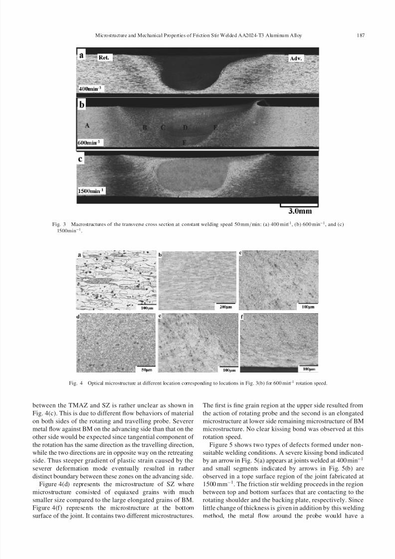
nous distributions of particles in SZ.Quantitative analysis of these micrographs revealed a clear
dependence of grain size on rotation speeds, which is shown
in Fig. 7. Grain size increases linearly from 2.6mm at
400 min1 to 7.1 mm at 1000 min1, while further increase of
rotation speed faster than 1000 min1 did not bring about
significant increase of grain size. A maximum grain size of
7.8mm was obtained at the rotation speed of 1500 min1.
The rotation speed dependence of grain size shown in
Figs. 6 and 7 is consistent with the report by Li et al.,16)
where the flow visualization and residual microstructures
associated with the dissimilar FSW of AA2024 to AA6061
was investigated. Figure 8 depicts a peak temperature at
bottom center position at SZ and HAZ for each rotationspeed. The temperatures increase in SZ and HAZ as rotation
Fig. 5 Defects observed in welded joints with unsuitable welding
conditions: (a) kissing bond at the welding root welded at 400min1,
(b) small segments at the top surface at 1500 min1.
Fig. 6 Optical microstructures of the stir zone: (a) 400 min1 (b) 600min1, (c) l000min1 and (d) 1500min1.
188 S. A. Khodir, T. Shibayanagi and M. Naka
7/27/2019 Microstructure and Mechanical Properties of Friction Stir Welded AA2024-T3 Aluminum Alloy
http://slidepdf.com/reader/full/microstructure-and-mechanical-properties-of-friction-stir-welded-aa2024-t3 5/9
speed increases. There is a larger incremental of temperature
in SZ between 400 and 1000min1 (722.5 K at 400 min1
and 774.0 K at 1000 min1) of rotations speeds than that
between 1000 and 1500 min1 (774.0 K at rotation speed
1000 and 796 K at 1500 min1). Temperature in HAZ
increases gradually from 679 K at 400 min1 to 707K at
1500 min1.
In general, the average grain size would decrease with
decreasing working temperature and increasing working
stain rate.10)
Since the recrystallized temperature decreaseswith increasing strain rate or rotation speeds,6) grain growth
would proceed faster as temperature increases. These
observation of increasing grain size with increasing temper-
ature in SZ is consistent with simple grain growth relations of
the form D2{ Do2 ¼ A expðQ= RT Þðt nÞ:
where D and Do represent the instantaneous (or residual) and
initial dynamically recrystallized grain sizes, respectively, A
is a constant, Q is the corresponding activation energy for
grain growth, R is the gas constant, T is the absolute
temperature, t is the time, and n is a constant usually taken as
unity. The deformation time would be taken to be equal to the
probe diameter divided by traverse speed.9) So the welding
time is also constant, it is apparent that as the process
temperature (T ) increases the value of D2– Do2 will increase.
The previous equation can be applied in high temperature
deformation. Some researchers9,10) working on FSW of other
alloys proved that the dependence of the dynamic recrystal-
lization grain size was found to have the same dependence onthe Zenner–Hollomon parameters as material deformed via
conventional hot working process where the working temper-
ature and strain rate, combined and expressed by the Zenner–
Hollomon parameters.
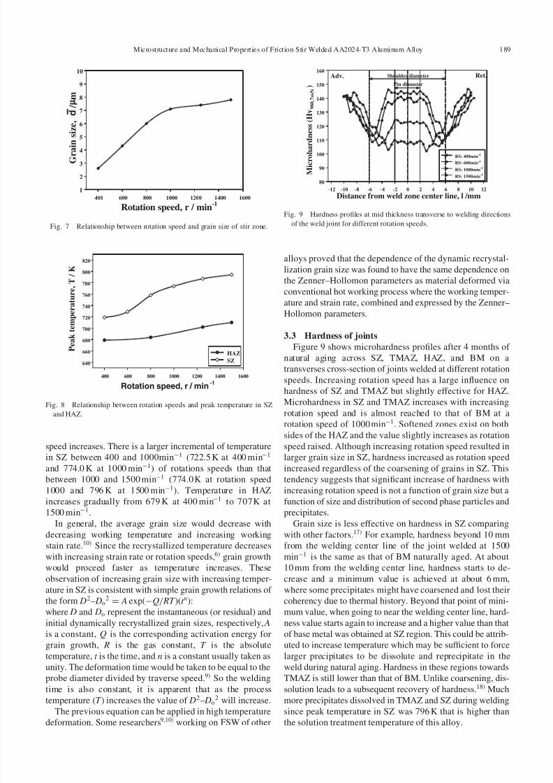
3.3 Hardness of joints
Figure 9 shows microhardness profiles after 4 months of
natural aging across SZ, TMAZ, HAZ, and BM on a
transverses cross-section of joints welded at different rotation
speeds. Increasing rotation speed has a large influence on
hardness of SZ and TMAZ but slightly effective for HAZ.
Microhardness in SZ and TMAZ increases with increasing
rotation speed and is almost reached to that of BM at arotation speed of 1000 min1. Softened zones exist on both
sides of the HAZ and the value slightly increases as rotation
speed raised. Although increasing rotation speed resulted in
larger grain size in SZ, hardness increased as rotation speed
increased regardless of the coarsening of grains in SZ. This
tendency suggests that significant increase of hardness with
increasing rotation speed is not a function of grain size but a
function of size and distribution of second phase particles and
precipitates.
Grain size is less effective on hardness in SZ comparing
with other factors.17) For example, hardness beyond 10 mm
from the welding center line of the joint welded at 1500min1 is the same as that of BM naturally aged. At about
10 mm from the welding center line, hardness starts to de-
crease and a minimum value is achieved at about 6 mm,
where some precipitates might have coarsened and lost their
coherency due to thermal history. Beyond that point of mini-
mum value, when going to near the welding center line, hard-
ness value starts again to increase and a higher value than that
of base metal was obtained at SZ region. This could be attrib-
uted to increase temperature which may be sufficient to force
larger precipitates to be dissolute and reprecipitate in the
weld during natural aging. Hardness in these regions towards
TMAZ is still lower than that of BM. Unlike coarsening, dis-
solution leads to a subsequent recovery of hardness.18) Much
more precipitates dissolved in TMAZ and SZ during welding
since peak temperature in SZ was 796 K that is higher than
the solution treatment temperature of this alloy.
-1400 600 800 1000 1200 1400 1600
1
2
3
4
5
6
7
8
9
10
Rotation speed, r / min
G r a i n s
i z e , d /
m
Fig. 7 Relationship between rotation speed and grain size of stir zone.
Rotation speed, r / min-1
400 600 800 1000 1200 1400 1600
640
660
680
700
720
740
760
780
800
820
HAZ
SZ
P e a k t e m p e r a t u r e , T /
K
Fig. 8 Relationship between rotation speeds and peak temperature in SZ
and HAZ.
Distance from weld zone center line, l /mm-12 -10 -8 -6 -4 -2 0 2 4 6 8 10 12
M i c r o h a r d n
e s s ( H v 9 8 0 . 7 m N )
80
90
100
110
120
130
140
150
160
RS: 400min-1
RS: 600min-1
RS: 1000min-1
RS: 1500min-1
Pin diameter
Shoulder diameter Ret.Adv.
Fig. 9 Hardness profiles at mid thickness transverse to welding directions
of the weld joint for different rotation speeds.
Microstructure and Mechanical Properties of Friction Stir Welded AA2024-T3 Aluminum Alloy 189

7/27/2019 Microstructure and Mechanical Properties of Friction Stir Welded AA2024-T3 Aluminum Alloy
http://slidepdf.com/reader/full/microstructure-and-mechanical-properties-of-friction-stir-welded-aa2024-t3 6/9
Figure 10 shows hardness profiles after 4 h and 4 months
of natural aging for the cases of 400 min1 (a) and
1500 min1 (b). In case of 400 min1 as shown in Fig. 10(a),
four hours of natural aging resulted in a slight increase of
hardness both in SZ and TMAZ but no significant increase
occurred both in HAZ and BM. Prolonged aging time of 4months brought about further increase of hardness in the
length of shoulder diameter and higher value of increment
was observed in the region comparable to the length of probe
diameter, but the value is still lower than that of BM. On the
other hand, Fig. 10(b) for the case of 1500 min1 represents a
significant increase of hardness in SZ and TMAZ after
natural aging of both 4 h and 4 months. Particularly 4-months
aging made SZ slightly harder than BM. HAZ showed less
increment of hardness and no change occurred in BM.
Hardness after 4 h of natural aging was higher both in SZ and
TMAZ at higher rotation speed than that at lower one.
This significant increase of hardness could be attributedmainly to the second phase particles size and distributions
(especially in SZ) and dislocation density (especially in
TMAZ), where increasing rotation speed mean increasing
strain. After four month of natural aging for the joint welded
at 400min1, the hardness increased at 5.5 mm from the
welding center line and maximum value increased by 8–
10 Hv in SZ and TMAZ, while at higher rotation speed such
as 1500 min1, hardness increased at 8 mm from welding
center line and maximum value increased by 15–20 Hv in SZ
and TMAZ as shown in Fig. 10. Some research works on the
other precipitation hardening alloys reported that SZ contains
a high density of dislocations,19) while other research
reported a low dislocation density in stir zone.3) Su et al.5)
observed high density of dislocation in many grains suggest-
ing that plastic deformation might have been introduced both
during FSW even after dynamic recrystallization and during
the cooling from the elevated weld temperature to ambient
temperature. Also it is clear that hardness partially recovered
in the softened HAZ in all welded joints after four months,
indicating that not all precipitates coarsened due to overaging
but some of these precipitates dissolved during joining and
precipitated again during the natural aging.
During FSW the temperature history and the deformationrate vary depending on the region through the joint. For
precipitation hardening aluminum alloys, these parameters
strongly influence the precipitation distribution that controls
the weld properties. Precipitations play dominant role such as
either a hardening agent at small sizes or detrimental to the
mechanical properties at large sizes. Hence the T3 treatment
brings about three possible changes in aging process in SZ,
TMAZ and HAZ where the initial precipitates structure
evolves: dissolution, over aging, and artificial aging. Hugh et
al.18) described softening behaviors of 2024-T3 Al alloy by
quenching after isothermal treatment at temperatures from
473 to 773 K for different holding times. Different behaviorsof precipitates take place at each temperature as follows;
– at 773 K, full strength recovery was observed for all the
hold time,
– at 673 K, partial recovery occurs, to a progressively
greater extent with increasing hold time,
– at 623 K the reverse is true—partial strength recovery
decreases as hold time increases.
According to them, the total hardness recovered in SZ was
due to mainly by natural aging because temperature in SZ
was more than 773 K. But the total amount of recovered
hardness in SZ cannot attributed only to the natural aging
since the cooling rate in FSW is low compared to the critical
cooling rate in quenching after the isothermal heating. Thecritical cooling rate is defined as the cooling rate where full
hardness recovery takes place at room temperature after
cooling. The amount of precipitation occurring during
cooling to room temperature controls the amount of
subsequent hardening since any further precipitation reaction
needs super-saturated solute remaining after cooling.
The hardness measured at 10 mm from the weld center line
of joints welded at all rotation speeds is the same as that of
BM. The temperature measured at that point for the case of
1500 min1 is equal to about 635 K, indicating that there is
neither overaging nor dissolution below that temperature.
Only artificial ageing occurred below that temperature.Overaging occurred at the temperature more than 635 K.
Precipitates start to dissolve at around 673 K in the region
about 8 mm from the welding center line and the phenom-
enon is accelerated with increasing temperature. Dissolving
of precipitates at that region resulted in hardness recovery
due to natural aging at room temperature as shown in
Fig. 10(b).
But partial recovery of hardness in the softened area of
HAZ (especially from 5 to 8 mm from the welding center line
for example in the case of 1500 min1) clearly observed after
the natural aging longer than 3 months. This may be
explained as follows. Precipitation process is explained in
terms of nucleation and growth. Driving force for the
nucleation strongly depends on the degree of super-satura-
tion, and growth kinetics is mainly affected by diffusion of
constituents that are affected by vacancies. In addition,
M i c r o h
a r d n e s s ( H v 9 8 0 . 7 m N )
80
90
100
110
120
130
140
150
160
After 4 hours
After 4 months
Ret.Adv.(a)
-12 -10 -8 -6 -4 -2 0 2 4 6 8 10 12
M i c r o h a r d n e s s ( H v 9 8 0 . 7 m N )
80
90
100
110
120
130
140
150
160
After 4 Hours
After 4 months
(b)
Distance from weld zone center line, l /mm
Shoulder diameter
Pin diameter
Fig. 10 Hardness profiles after 4 h from welding and naturally aged after 4
months at mid thickness transverse to welding directions of the weld joint.
(a) 400min1, (b) 1500min1.
190 S. A. Khodir, T. Shibayanagi and M. Naka

7/27/2019 Microstructure and Mechanical Properties of Friction Stir Welded AA2024-T3 Aluminum Alloy
http://slidepdf.com/reader/full/microstructure-and-mechanical-properties-of-friction-stir-welded-aa2024-t3 7/9
nucleation sites are given by dislocations, vacancies and
other heterogeneous regions in lattice. The degree of super-
saturation in HAZ would rather decreased than that in SZ
since temperature increase in HAZ is less than that in SZ.
Therefore this difference of chemical driving force should
have played an important role in the difference of driving
force for the nucleation resulting in the difference of timerequired for the recovery of hardness observed.
Besides the role of chemical driving force, lattice defects
such as dislocations and point defects introduced during FSW
should be taken into account as nucleation sites. Vacancies
also play dominant role in diffusion process of solute atoms
to nucleation site and growing precipitates. Since HAZ
experienced a lower temperature than SZ during FSW,
dislocations would have larger chance to remain resulting in
giving more nucleation sites. Equilibrium amount of vacan-
cies is larger at higher temperature, and larger cooling rate
brings about larger amount of quench-in vacancies. Thus
HAZ, having lower maximum temperature and cooling ratethan SZ, would contain less amounts of the defects and
eventually give less nucleation sites and diffusivity of
constituents.
The temperature history during FSW affects the chemical
driving force, nucleation sites and diffusivity in terms of
many factors such as degree of super-saturation, dislocation
density and amounts of vacancies remained after cooling
down to room temperature. As a combined effect based on
these fundamental factors, different recovery process of
hardness proceeded as observed in the present joints.
The slight increase of hardness in HAZ with increasing
rotation speed as shown in Fig. 9 could be explained by the
relatively increasing heating or cooling rate during welding.Figure 11 shows temperature change with time at a point in
HAZ during FSW at 400 and 1500 min1 of rotations speeds.
Heating and cooling rates could be calculated from temper-
ature (T /K) changes with time (t /s) in temperature range
from 635 K to peak temperature corresponding for each
rotation speed as shown in Fig. 11. This temperatures range
was selected according to the temperature measured at
10 mm from the welding center line, where coarsening of
precipitates starts after 635 K. For 400 min1, heating and
cooling rates were 7.8 and 6.0 K/s respectively. While
heating and cooling rates at 1500 min1 were 15.6 and
10.2 K/s, respectively. So the amount of precipitates coars-
ened during heating decreased with increasing heating ratesince increasing heating rate reduce the time for precipitates
to grow and hence leads to hardness increase in HAZ. Also
increasing cooling rate after welding increases the amount of
supersaturated solute which will be available for further
precipitation reaction at room temperature.
3.4 Tensile properties of joints
Figure 12 shows the tensile properties of joints welded at
different rotation speeds. Tensile strength, yield strength, and
elongation increased with increasing rotation speeds but still
lower than those of base metal, especially the elongation of
the joints is much lower than that of base metal and its
maximum value was about 12.4% at 1250 min1 (about half of base metal). This could be attributed to the coarsening of
the precipitates in HAZ.20) The maximum tensile strength of
the joints was 402 MPa which was achieved at 1250 min1 of
rotation speed and the joint efficiency was 88.3%. The lowest
tensile properties were obtained for the joint welded at
400 min1 due to lower hardness and severe kissing bond at
the root of weld as shown in Fig. 5(a). Also, due to kissing
bond at 1500 min1 and small segments observed in a top
surface at 1500 min1 Fig. 5(b), the tensile properties of
joints slightly decreased less than those of joint welded at
1250 min1.
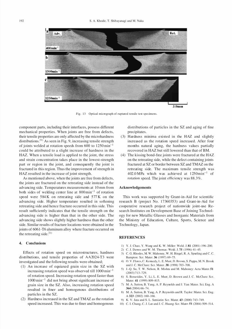
Figure 13 shows the changes in fracture location of tensiletested specimens welded at three kinds of rotation speeds.
Fracture occurs in SZ for the specimen welded at a rotation
speed of 400 min1 as shown in (a). In this case, crack
propagated almost center position of SZ and seems to be in a
brittle manner. As rotation speed raised to 1500 min1, the
crack changed to propagate along the border between SZ and
TMAZ on the retreating side as shown in (b). On the other
hand, when the joints are fabricated at rotation speed from
600 to 1250 min1 where no defects exist, crack propagated
in HAZ on the retreating side as seen in (c) for the case of
1250 min1.
Tensile properties and fracture location of FSW joints are,
to large extent, depend on the welding defects and hardness
distributions of the joints, of which in return are function of
the welding parameters. In addition, the friction-stir-welded
joint is known as a heterogeneous composite and its different
Welding time, t / s10 20 30 40 50 60 70 80 90 100
P e a k t e m p e r a t u r e , T / K
350
400
450
500
550
600
650
700
750
400min-1
1500min-1
Heating or cooling rate
= tan = T(K) / t (s)
T / ( K )
t / (s)
Fig. 11 Temperature change by time at the HAZ during FSW of 400,
1500min1 rotations speeds.
Rotation speed, r / min-1
200 400 600 800 1000 1200 1400 1600
S t r e n g t h ,
/ M P a
240
270
300
330
360
390
420
450
E l o
n g a t i o n ( % )
2
4
6
8
10
12
14
16
18
20
Yield Strength
Tensile strength
Elongation
Fig. 12 Relationship between rotation speed and tensile properties of the
welded joints.
Microstructure and Mechanical Properties of Friction Stir Welded AA2024-T3 Aluminum Alloy 191
7/27/2019 Microstructure and Mechanical Properties of Friction Stir Welded AA2024-T3 Aluminum Alloy
http://slidepdf.com/reader/full/microstructure-and-mechanical-properties-of-friction-stir-welded-aa2024-t3 8/9
component parts, including their interfaces, possess different
mechanical properties. When joints are free from defects,
their tensile properties are only affected by the microhardness
distributions.21) As seen in Fig. 9, increasing tensile strength
of joints welded at rotation speeds from 600 to 1250 min1
could be attributed to a slight increase of hardness in the
HAZ. When a tensile load is applied to the joint, the stress
and strain concentration takes place in the lowest-strength
part or region in the joint, and consequently the joint is
fractured in this region. Thus the improvement of strength in
HAZ resulted in the increase of joint strength.As mentioned above, when the joints are free from defects,
the joints are fractured on the retreating side instead of the
advancing side. Temperatures measurements at 10 mm from
both sides of welding center line at 800 min1 of rotation
speed were 584 K on retreating side and 577 K on the
advancing side. Higher temperature resulted in softening
retreating side and hence fracture occurred in this side. This
result sufficiently indicates that the tensile strength on the
advancing side is higher than that in the other side. The
advancing side shows slightly higher hardness than the other
side. Similar results of fracture locations were obtained in the
joints of 6061-T6 aluminum alloy where fracture occurred onthe retreating side.21)
4. Conclusions
Effects of rotation speed on microstructures, hardness
distributions, and tensile properties of AA2024-T3 were
investigated and the following results were obtained;
(1) An increase of equiaxed grain size in the SZ with
increasing rotation speed was observed till 1000 min1
of rotation speed. Increasing rotation speed faster than
1000 min1 did not bring about significant increase of
grain size in the SZ. Also, increasing rotation speed
resulted in finer and homogenous distributions of
particles in the SZ.
(2) Hardness increased in the SZ and TMAZ as the rotation
speed increased. This was due to finer and homogenous
distributions of particles in the SZ and aging of fine
precipitates.
(3) Hardness minima existed in the HAZ and slightly
increased as the rotation speed increased. After four
months natural aging, the hardness values partially
recovered in HAZ but still lowered than that of BM.
(4) The kissing bond-free joints were fractured at the HAZ
on the retreating side, while the defect containing joints
fractured at SZ or border between SZ and TMAZ on the
retreating side. The maximum tensile strength was
402.0 MPa which was achieved at 1250min1 of rotation speed. The joint efficiency was 88.3%.
Acknowledgements
This work was supported by Grant-in-Aid for scientific
research B (project No. 17360353) and Grant-in-Aid for
cooperative research project of nationwide joint-use Re-
search Institutes on Development Base of Joining Technol-
ogy for new Metallic Glasses and Inorganic Materials from
the Ministry of Education, Culture, Sports, Science and
Technology, Japan.
REFERENCES
1) Y. J. Chao, Y. Wang and K. W. Miller: Weld. J. 81 (2001) 196–200.
2) C. J. Dawes and W. M. Thomas: Weld. J. 75 (1996) 41–45.
3) C. G. Rhodes, M. W. Mahoney, W. H. Bingel, R. A. Spurling and C. C.
Bampton: Scr. Mater. 36 (1997) 69–75.
4) O. V. Flores, C. Kennedy, L. E. Murr, D. Brown, S. Pappu, M. N. Brook
and J. C. McClure: Scr. Mater. 38 (1998) 703–708.
5) J.-Q. Su, T. W. Nelson, R. Mishra and M. Mahoney: Acta Mater. 51
(2003) 713–729.
6) S. Benavides, Y. Li, L. E. Murr, D. Brown and J. C. McClure: Scr.
Mater. 41 (1999) 809–815.
7) M. A. Sutton, B. Yang, A. P. Reynolds and J. Yan: Mater. Sci. Eng. A
364 (2004) 66–74.8) M. A. Sutton, B. Yang, A. P. Reynolds and R. Taylor: Mater. Sci. Eng.
A 323 (2002) 160–166.
9) K. V. Jata and S. L. Semiatin: Scr. Mater. 43 (2000) 743–749.
10) C. I. Chang, C. J. Lee and J. C. Huang: Scr. Mater. 51 (2004) 509–514.
Fig. 13 Optical micrograph of ruptured tensile test specimens.
192 S. A. Khodir, T. Shibayanagi and M. Naka

7/27/2019 Microstructure and Mechanical Properties of Friction Stir Welded AA2024-T3 Aluminum Alloy
http://slidepdf.com/reader/full/microstructure-and-mechanical-properties-of-friction-stir-welded-aa2024-t3 9/9
11) C. G. Rhodes, M. W. Mahoney, W. H. Bingel and M. Calabrese: Scr.
Mater. 48 (2003) 1451–1455.
12) M. J. Jones, P. Heurtier, C. Desrayaud, F. Montheillet, D. Allehaux and
J. H. Driver: Scr. Mater. 52 (2005) 693–697.
13) G. Biallas, R. Braun, C. Dalle Donne, G. Staniek and W. A. Kaysser:
Proceedings of the 1st International Symposium on Friction Stir
Welding, (The Welding Institute, Cambridge, UK) Thousand Oaks
California, (1999) 14–16 June.14) R. Zettle, S. Lomolino, J. Dossantos, T. Donath, F. Beckmann, T.
Lippman and D. Lohwasser: Proceeding of IIW Pre-Assembly Meeting
on FSW (Nagoya, Japan, 2004) 65–70.
15) A. F. Norman, I. Brough and P. B. Prangnel: Mater. Sci. Forum 331–
337 (2000) 1713–1718.
16) Ying Li, L. E. Murr and J. C. McClure: Mater. Sci. Eng. A 271 (1999)
213–223.
17) H. G. Salem: Scr. Mater. 49 (2003) 1103–1110.
18) H. R. Shercliff, J. R. Michael, A. Taylor and T. L. Dickerson:
Mecanique & Industries 6 (2005) 25–35.
19) K. V. Jata, K. K. Sankaran and J. J. Ruschau: Metall. Mater. Trans. A
31 (2000) 2181.20) D. S. Thompson: Metall. Mater. Trans. A 6 (1975) 671–683.
21) H. J. Liu, H. Fujii, M. Maeda and K. Nogi: J. Mater. Process. Technol.
142 (2003) 692–696.
Microstructure and Mechanical Properties of Friction Stir Welded AA2024-T3 Aluminum Alloy 193
Related Documents