Microstructural and Mechanical Evaluation of Laser-Assisted Cold Sprayed Bio-ceramic Coatings: Potential Use for Biomedical Applications Monnamme Tlotleng, Esther Akinlabi, Mukul Shukla, and Sisa Pityana (Submitted July 16, 2014; in revised form October 1, 2014) Bio-composite coatings of 20 wt.%, HAP and 80 wt.%, HAP were synthesized on Ti-6Al-4V substrates using LACS technique. The coatings were produced with a laser power of 2.5 kW, powder-laser spot trailing by 5 s. The coatings were analyzed for the microstructures, microhardness, composition, and bio- corrosion using SEM-EDS, XRD, hardness tester, and Metrohm PGSTAT101 machine. SEM images indicated least pores and crack-free coating with dark-spots of Ti-HAP for the 20 wt.%, HAP as op- posed to the 80 wt.%, HAP coating which was solid, porous and finely cracked and had semi-melted Ti- HAP particles. The EDS mappings showed high content of HAP for the 80 wt.%, HAP coating. The diffraction patterns were similar, even though the Ti-HAP peak was broader in the 80 wt.%, HAP coating and the HAP intensities were lower for this coating except for the (004) peak. The hardness values taken at the interface inferred that the 80 wt.%, HAP coating was least bonded. It was possible to conclude that when this phase material increased the hardness dropped considerably. The bio-corrosion tests indicated that the presence of HAP in coating leads to a kinetically active coating as opposed to pure titanium coating. Keywords composite, hydroxyapatite, laser-assisted cold spray, laser power, titanium 1. Introduction Metals and their alloys can be used in tissue engi- neering as permanent or temporary scaffolds. Metals such as stainless steel (SS) have good mechanical properties (stiffness, elasticity and ductility) that are necessary for the fabrication of long bone and screws, but they are prone to corrosion while they are non-biocompatible. For this understanding, SS scaffolds are preferred only as temporary implants while cobalt alloys (CoCrMo) are favorable for orthopedics given that they are good elec- trical conducting materials and have better corrosion and fatigue-resistant properties. Unfortunately, CoCrMo have stiffness greater than that of SS and titanium alloy (Ti- 6Al-4V), hence they have not been used successfully for the long bone replacement applications (Ref 1-3). Ti-6Al- 4V is bioinert in that it does not form an immediate chemical bond with the natural bone upon implantation (Ref 4, 5). To date, Ti-6Al-4V is the most preferred material over all material-metal alloys used for the orthopedic applications (Ref 3-5) given its attractive fea- tures. The low cytotoxicity reported with Ti-6Al-4V is triggered by V ions which leach into the human blood system when the implant was left in service for long (Ref 6). V ions can cause long-term diseases such as Alzhei- merÕs, neuropathy, and Osteomalacia (Ref 3). It is pro- posed that to prevent these post implantation diseases from occurring while inducing the Osseo-integration of Ti- 6Al-4V implants, their surface properties must be altered by coating with hydroxyapatite (HAP) (Ref 7). Hydroxyapatite is the most researched bio-ceramic material, in the field of biomedical engineering for scaffolds manufacturing, of all the calcium phosphate family (CaP); not because of its crystallographic similarities likened to the natural bone; but this is since HAP can induce osteo-con- ductivity and integrate the coated-metal implant with the natural human tissues in vivo (Ref 8-10, 11, 12). The attachment of implants with natural bones is possible since HAP is characterized by natural porosity in which the tissue Monnamme Tlotleng, Laser Material Processing, National Laser Center CSIR, Pretoria 0001, South Africa and Department of Mechanical Engineering Science, University of Johannesburg, Auckland Park, Kingsway Campus, Johannesburg 2006, South Africa; Esther Akinlabi, Department of Mechanical Engineering Science, University of Johannesburg, Auckland Park, Kingsway Campus, Johannesburg 2006, South Africa; Mukul Shukla, Department of Mechanical Engineering, MNNIT, Allahabad 211004, UP, India and Department of Mechanical Engineering Technology, University of Johannesburg, Doornfontein Campus, Johannesburg 2006, South Africa; and Sisa Pityana, Laser Material Processing, National Laser Center CSIR, Pretoria 0001, South Africa and Department of Chemical and Metallurgical Engineering, Tshwane University of Technology, Pretoria 0001, South Africa. Contact e-mails: [email protected]. za and [email protected]. JTTEE5 DOI: 10.1007/s11666-014-0199-6 1059-9630/$19.00 Ó ASM International Journal of Thermal Spray Technology Peer Reviewed

Welcome message from author
This document is posted to help you gain knowledge. Please leave a comment to let me know what you think about it! Share it to your friends and learn new things together.
Transcript
Microstructural and Mechanical Evaluationof Laser-Assisted Cold Sprayed Bio-ceramic
Coatings: Potential Use for BiomedicalApplications
Monnamme Tlotleng, Esther Akinlabi, Mukul Shukla, and Sisa Pityana
(Submitted July 16, 2014; in revised form October 1, 2014)
Bio-composite coatings of 20 wt.%, HAP and 80 wt.%, HAP were synthesized on Ti-6Al-4V substratesusing LACS technique. The coatings were produced with a laser power of 2.5 kW, powder-laser spottrailing by 5 s. The coatings were analyzed for the microstructures, microhardness, composition, and bio-corrosion using SEM-EDS, XRD, hardness tester, and Metrohm PGSTAT101 machine. SEM imagesindicated least pores and crack-free coating with dark-spots of Ti-HAP for the 20 wt.%, HAP as op-posed to the 80 wt.%, HAP coating which was solid, porous and finely cracked and had semi-melted Ti-HAP particles. The EDS mappings showed high content of HAP for the 80 wt.%, HAP coating. Thediffraction patterns were similar, even though the Ti-HAP peak was broader in the 80 wt.%, HAPcoating and the HAP intensities were lower for this coating except for the (004) peak. The hardnessvalues taken at the interface inferred that the 80 wt.%, HAP coating was least bonded. It was possible toconclude that when this phase material increased the hardness dropped considerably. The bio-corrosiontests indicated that the presence of HAP in coating leads to a kinetically active coating as opposed topure titanium coating.
Keywords composite, hydroxyapatite, laser-assisted coldspray, laser power, titanium
1. Introduction
Metals and their alloys can be used in tissue engi-neering as permanent or temporary scaffolds. Metals suchas stainless steel (SS) have good mechanical properties(stiffness, elasticity and ductility) that are necessary forthe fabrication of long bone and screws, but they areprone to corrosion while they are non-biocompatible. For
this understanding, SS scaffolds are preferred only astemporary implants while cobalt alloys (CoCrMo) arefavorable for orthopedics given that they are good elec-trical conducting materials and have better corrosion andfatigue-resistant properties. Unfortunately, CoCrMo havestiffness greater than that of SS and titanium alloy (Ti-6Al-4V), hence they have not been used successfully forthe long bone replacement applications (Ref 1-3). Ti-6Al-4V is bioinert in that it does not form an immediatechemical bond with the natural bone upon implantation(Ref 4, 5). To date, Ti-6Al-4V is the most preferredmaterial over all material-metal alloys used for theorthopedic applications (Ref 3-5) given its attractive fea-tures. The low cytotoxicity reported with Ti-6Al-4V istriggered by V ions which leach into the human bloodsystem when the implant was left in service for long (Ref6). V ions can cause long-term diseases such as Alzhei-mer�s, neuropathy, and Osteomalacia (Ref 3). It is pro-posed that to prevent these post implantation diseasesfrom occurring while inducing the Osseo-integration of Ti-6Al-4V implants, their surface properties must be alteredby coating with hydroxyapatite (HAP) (Ref 7).
Hydroxyapatite is the most researched bio-ceramicmaterial, in the field of biomedical engineering for scaffoldsmanufacturing, of all the calcium phosphate family (CaP);not because of its crystallographic similarities likened to thenatural bone; but this is since HAP can induce osteo-con-ductivity and integrate the coated-metal implant with thenatural human tissues in vivo (Ref 8-10, 11, 12). Theattachment of implants with natural bones is possible sinceHAP is characterized by natural porosity in which the tissue
Monnamme Tlotleng, Laser Material Processing, National LaserCenter CSIR, Pretoria 0001, South Africa and Department ofMechanical Engineering Science, University of Johannesburg,Auckland Park, Kingsway Campus, Johannesburg 2006, SouthAfrica; Esther Akinlabi, Department of Mechanical EngineeringScience, University of Johannesburg, Auckland Park, KingswayCampus, Johannesburg 2006, South Africa; Mukul Shukla,Department of Mechanical Engineering, MNNIT, Allahabad211004, UP, India and Department of Mechanical EngineeringTechnology, University of Johannesburg, Doornfontein Campus,Johannesburg 2006, South Africa; and Sisa Pityana, LaserMaterial Processing, National Laser Center CSIR, Pretoria0001, South Africa and Department of Chemical andMetallurgical Engineering, Tshwane University of Technology,Pretoria 0001, South Africa. Contact e-mails: [email protected] and [email protected].
JTTEE5
DOI: 10.1007/s11666-014-0199-6
1059-9630/$19.00 � ASM International
Journal of Thermal Spray Technology
Peer
Revie
wed
can grow around and into the scaffolds. In addition to itbeing porous, HAP is also brittle, heat sensitive, and non-ductile. HAP possesses poor mechanical properties such aslow plasticity, fatigue, and creep resistance (Ref 13). Due tothe observed poor mechanical properties; brittleness andporousness, HAP may not be used as a bulk material forstructural support, (Ref 14, 15, 16), except as a compressivematerial. As a compressive material, HAP coating canpotentially suppress V ions, be flexible at the contact pointwith the implant, more so it will accelerate the attachmentand growth of the human natural tissue around and into themetal scaffolds. The porous nature of HAP makes it pos-sible that after Osseo-integration nutrition can flow withinthe scaffolds (Ref 7, 8, 17).
The heat sensitivity and lack of plastic deformation ofHAP are of greater concern where this material limits thechoice of surface coating techniques from which it can bedeposited onto Ti-6Al-4V for biomedical applications.Even so, research continues to develop and establish otherindustrial acceptable methods from which HAP coatingscan be fabricated on Ti-6Al-4V. Several techniques havebeen used successfully to modify the metallic surface ofTi-6Al-4V alloy by coating it with a thin, continuous layerof HAP (Ref 7, 10, 18, 19). Traditionally, HAP has beensuccessfully deposited on Ti-6Al-4V using electrochemical(cathodic) deposition (Ref 20), Sol-gel (Ref 21), magne-tron sputtering (9), pulse laser deposition (Ref 22, 23),laser cladding (Ref 24, 25), thermal spraying techniques(Ref 26), seeded hydrothermal deposition (Ref 14), coldspraying techniques (Ref 27, 28), Laser-engineered netshaping technique (Ref 8), and laser-assisted depositionmethods (Ref 29). The most preferred method of pro-ducing thin, continuous films of HAP on base metals isplasma spraying. Plasma spraying is desirable for its highdeposition rates efficiencies, making it an acceptableindustrial technique to be used in depositing HAP coat-ings. Nonetheless, there is an evidence that proves defin-itively that the HAP coatings deposited with plasma andflame-based spray techniques contain decomposed phasesof HAP. These decomposed phases [calcium oxide (CaO);a- and b-tricalcium phosphate (TCP) and tetra calciumphosphate (TTCP)] which are due to the high processtemperatures involved during depositions affect the per-formance and life-span of the coating during service. Thedisadvantages and advantages of HAP coatings depositedwith various techniques are presented and discussed indetails by Doronzhkin (Ref 7).
Meanwhile, it is explained that wet deposition tech-niques cannot achieve thick, continuous HAP coatingsmaking them expensive to operate and undesirable.Plasma spraying technique produces HAP coatings thatare weakly bonding to the substrate at the interface,accelerated resorption during service and dilution. Thedelamination and rapid resorption of the coating duringservice are ascribed to the presence of the decomposedphases of HAP in the coating while the weakenedbonding between the coating and the substrate is attributedto the vast thermal mismatches that exist between HAP(13.3 9 10�6 K�1) and Ti-6Al-4V (8.4-8.8 9 10�6 K�1)(Ref 30). To address the issues around the characteristics of
HAP coating produced with plasma spraying while reduc-ing the process temperatures, cold spray (CS) techniquewas developed. CS is an industrial technique that retains allthe advantages of plasma spraying. Consequently, CS can-not deposit pure HAP powder since it lacks the plasticdeformation, a required characteristic for any materialbeing cold sprayed. Meanwhile, CS techniques are costineffective since they require expensive process gas (He-lium) and heating sources (Ref 31, 32). To overcome theshortcomings presented for both plasma and cold sprayingtechniques, during HAP deposition, many studies use bio-composite powders comprising a metal (typically Ti) andHAP. The metal in the composite is able to give strength tothe HAP, and induce plastic deformation to HAP whilereducing the thermal mismatching that exists between theTi-6Al-4V substrate and HAP powder during deposition.
Both plasma and CS techniques have been used, byindependent researchers, to deposit a bio-compositecoating (Ref 4, 5, 9, 27-29). Plasma-sprayed bio-compositecoatings yield with similar problems as presented before.CS is an alternative industrial technique to plasmaspraying, even though it limits the number of powderswhich can be deposited and requires expensive processinggas like Helium (He) and heating source for the process toyield high deposition rates and be efficient. To circumventthe technical shortcomings present against CS techniques,laser enabling techniques are investigated. It is presentedin (Ref 27) that CS can deposit bio-composite coating, butwith reduced HAP content. The authors believe that laser-enabled CS techniques can improve on the quantity ofHAP in the coating. This study therefore presents bio-composite coatings deposited with laser-assisted coldspray (LACS). LACS is an extension of CS and in no waydo we believe it replaces CS at the industrial scale.
LACS is a new concept of CS techniques. LACS set-upcomprises mainly a De Laval supersonic diverging-con-verging nozzle, a process gas and the powder particleentraining gas, and high power laser which serve as aheating source. The technical basics and the advantages ofthis technique over CS are discussed elsewhere by thecorresponding author (Ref 32). LACS was first demon-strated by Bray et al. (Ref 31), in 2006, at the InternationalCongress of Applications of Laser and Electro-Optics heldin the United State of America. According to Lupoi et al.(Ref 33), during LACS deposition, a laser source preheatthe substrate; hence therefore removing the oxide layerwhile being able to simultaneously preheat the powder-particles below melting point to temperatures that rangebetween 30% and 70% of the particle melting point. Thisheat provides for the softening of the particles strengthwhile allowing the particles to deform and build up thecoating upon hitting the surface.
The effect of laser power during LACS deposition isthe most studied phenomena. For example, Lupoi et al.(Ref 34) illustrated by means of micrographs how titaniumpowder can bond to the metallic substrate with an increasein substrate-powder temperature. Olakanmi et al. (Ref 32)studied the effect of laser on the deposition mechanism ofaluminum powder. All reviewed studies support the initialanalogy by Brodmann (Ref 35), and agree that the suffi-
Journal of Thermal Spray Technology
Peer
Revie
wed
cient energy provided by laser source during laser depo-sition can cause the oxide film surrounding the particles tobe brittle and crack open during impact thereby leading tothe formation of a surface coating (Ref 32, 35). To date,only Olakanmi et al. (Ref 32) and Bray et al. (Ref 31)have successfully produced metal coatings using high-pressure LACS systems, but nothing yet on bio-compos-ites of Ti and HAP. In this study, a LACS technique wasused to deposit bio-composite powders consisting of Tiand HAP. LACS bio-composite coatings presented in thisstudy were named 20 wt.%, HAP and 80 wt.%, HAP. Themicrostructures of these coatings were studied usingoptical microscope and focal ion beam, scanning electronmicroscope capable of reporting on elemental analysisusing electron dispersive spectroscope (FIB, SEM-EDS).X-ray diffraction was used to match the phase identity ofthe feedstock powder to the coatings while Vickers�hardness machine and Metrohm PGSTAT101 were usedto study the micro-hardness and bio-corrosion of thecoatings, respectively.
2. Materials and Methods
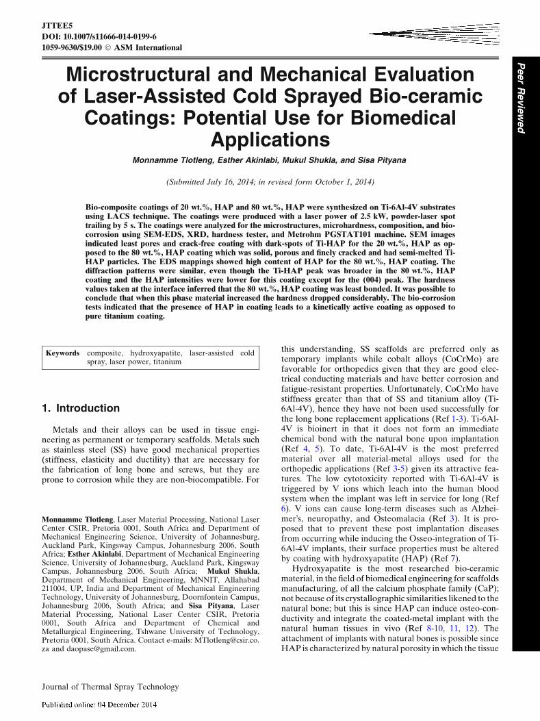
A powder displayed by Fig. 1 was achieved bymechanically milling together a commercially pure (CP),spherical titanium (Ti) powder of particle size distribution45-90 lm supplied by TLS Technik GmbH and HAP (90)of particles size 62.1 lm supplied by Plasma Biotal, UnitedKingdom. Steel balls were used to mechanically grinding(CP)-Ti and HAP (90) into a bio-composite powder. Twosets of powders, viz., 20 wt.%, HAP and 80 wt.%, HAPwere produced. The powders were tested for flowabilityusing FT4 Powder Rheometer which had a hardenedstainless steel blade diameter of 24.5 mm and a borosili-cate testing vessels having a diameter of 25 mm. Thepowder composition analyzed with FIB, SEM-EDS isshown in Fig. 1. Titanium alloy (Ti-6Al-4V) substrates ofdimensions 70 9 70 9 5 mm3 were available for use asdeposition surfaces. The substrates were initially sand-blasted to improve their adhesion properties.
2.1 LACS Set-Up
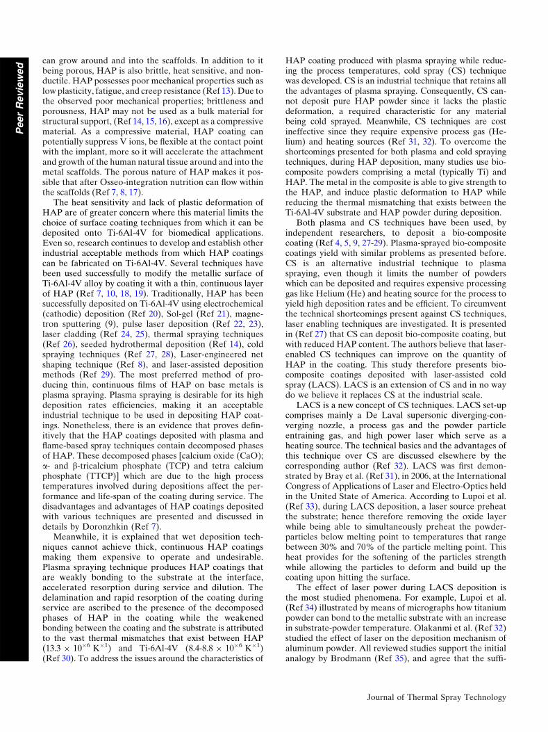
LACS equipment used in this study was located at theCSIR National Laser (NLC/CSIR), Pretoria, South Afri-ca. The set-up included a 4.4 kW, 044 Rofin Nd:YAG(Rofin DY 044) laser system of 1.06 lm wavelength, aAT-12000HPHV 5000PSI (35 bar) powder feeder (Ther-mach Inc., Appleton), compressed Nitrogen bulk gas tankwith controlled regulation and a de Laval supersonicnozzle. The converging-diverging (de Laval) DLV-180nozzle used in this study was manufactured and suppliedfrom the Centre for Industrial Photonics, Institute forManufacturing, University of Cambridge, UK. Figure 2shows this equipment.
Figure 2 shows the equipment used to set-up the LACSused in this study to deposit the bio-composite powders.
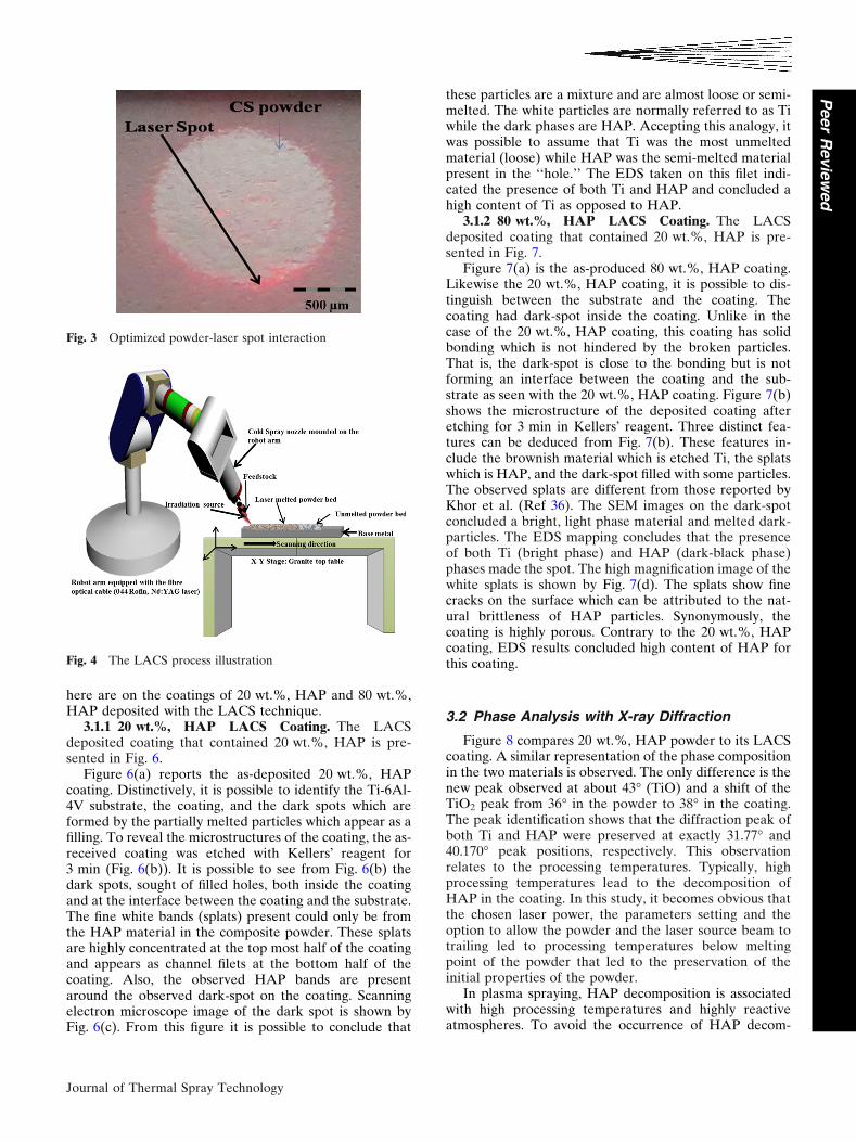
Figure 2(a) shows the in-let and out-let of the high-pres-sure Nitrogen (N2) gas that was used as both theentraining and processing gas. Regulators, pressure gagesand the taps were attached to both ends of the gas lines.The gas on the left side was the entraining gas and con-nected to the Thermal high pressure, regulated powderfeeder that had a releasing, venting valve (Fig. 2b). Thegas on the right-hand side connected to the De Laval,supersonic diverging-converging nozzle shown in Fig. 2(c).The powder stream and the N2 gas recombined inside thenozzle were accelerated through the nozzle at highsupersonic speeds. The nozzle was mounted on the Kukarobot arm which allowed for the simultaneous scanning ofthe laser source spot and the powder spot across thedepositing surface. A well optimized laser-powder spot ischaracterized by the spot that has the laser spot lockingwithin it the powder spot (See Fig. 2). This step allows forthe powder to be fully preheated and deposit efficiently.The bio-composites coatings presented in this study wereachieved by allowing the powder-jet stream to trail behindthe laser spot by 15 mm with a delayed time of 1.5 s. Sucha spot is shown in Fig. 3.
Figure 4 and 5 illustrate the phenomena of LACS coatingand the actual process set-up that was used in this study.Figure 4 shows powder-laser interaction, melted and un-melted powder particle, and the base metal without dilution.Figure 5(c) shows the nozzle mounted on the Kuka robotarm, the process chamber and the bracket that held thenozzle on the set angle. In this study, the nozzle was heldperpendicular to the substrate at the stand-off distance of50 mm while the laser beam was inclined at 15� and the laser-powder spot traverse speed, laser power, and the depositionpressure were kept constant at 30 mm/s, 2.5 kW, and16.5 bars, respectively. The choice of the laser power wasbased on the deposition characteristics of (CP)-Ti coatings.
2.2 Sample Analysis
The produced coatings were sectioned then ground andpolished to a 0.04 micron (OP-S suspension) surface finishwith a Struers TegraForce-5 auto/manual polisher. Postpolishing, the selected coatings were etched with Kellers�reagent for 3 min and then analyses for microstructuresusing light optical microscope connected to the Analysis�software. The best samples were analyzed with Auriga,CrossBeam FIB Workstation with GEMINI FESEM col-umn equipped with The Oxford X-Max instrument with20-mm square window, Aztec Software. Imaging by SEMallowed for in-depth microstructural analyses. Also, SEM-EDS component was used to characterize samples fortheir composition. The phase present in the coatings wasanalyzed with Panalytical XPert PRO PW 3040/60 x-raydiffraction (XRD) with Cu Ka monochromater radiationsource. The mechanical micro-hardness values of thecoatings were conducted using Matsuzawa Seiko Vickersmicro-hardness tester model MHT-1. An indenting load of300 g and a 10 s dwell time were used for each hardnessindent action. The selected bio-ceramic coatings were sentfor bio-corrosion analysis using Metrohm PGSTAT101.
Journal of Thermal Spray Technology
Peer
Revie
wed
3. Results and Discussion
3.1 LACS Coatings Microstructures
LACS technology has recently surfaced as a metaldepositing technique for surface coat making. In thisregard, it is now evident that the open literature is scant ofmicrostructures or nay scientific results relating to HAP or
bio-composite coatings that were fabricated using LACS.However, there are results from the literature presentedon these types of coating, but from traditional cold sprayand plasma spraying techniques. Given this understand-ing, the results reported in this study were compared orcontrasted to the results that were presented on bothplasma and cold spray techniques. The results reported
Fig. 1 Morphology and composition of the Ti-HAP powders used in this study
Fig. 2 Equipment used to set-up LACS system
Journal of Thermal Spray Technology
Peer
Revie
wed
here are on the coatings of 20 wt.%, HAP and 80 wt.%,HAP deposited with the LACS technique.
3.1.1 20 wt.%, HAP LACS Coating. The LACSdeposited coating that contained 20 wt.%, HAP is pre-sented in Fig. 6.
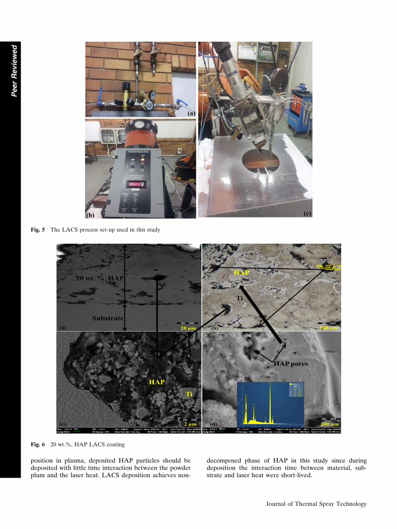
Figure 6(a) reports the as-deposited 20 wt.%, HAPcoating. Distinctively, it is possible to identify the Ti-6Al-4V substrate, the coating, and the dark spots which areformed by the partially melted particles which appear as afilling. To reveal the microstructures of the coating, the as-received coating was etched with Kellers� reagent for3 min (Fig. 6(b)). It is possible to see from Fig. 6(b) thedark spots, sought of filled holes, both inside the coatingand at the interface between the coating and the substrate.The fine white bands (splats) present could only be fromthe HAP material in the composite powder. These splatsare highly concentrated at the top most half of the coatingand appears as channel filets at the bottom half of thecoating. Also, the observed HAP bands are presentaround the observed dark-spot on the coating. Scanningelectron microscope image of the dark spot is shown byFig. 6(c). From this figure it is possible to conclude that
these particles are a mixture and are almost loose or semi-melted. The white particles are normally referred to as Tiwhile the dark phases are HAP. Accepting this analogy, itwas possible to assume that Ti was the most unmeltedmaterial (loose) while HAP was the semi-melted materialpresent in the ‘‘hole.’’ The EDS taken on this filet indi-cated the presence of both Ti and HAP and concluded ahigh content of Ti as opposed to HAP.
3.1.2 80 wt.%, HAP LACS Coating. The LACSdeposited coating that contained 20 wt.%, HAP is pre-sented in Fig. 7.
Figure 7(a) is the as-produced 80 wt.%, HAP coating.Likewise the 20 wt.%, HAP coating, it is possible to dis-tinguish between the substrate and the coating. Thecoating had dark-spot inside the coating. Unlike in thecase of the 20 wt.%, HAP coating, this coating has solidbonding which is not hindered by the broken particles.That is, the dark-spot is close to the bonding but is notforming an interface between the coating and the sub-strate as seen with the 20 wt.%, HAP coating. Figure 7(b)shows the microstructure of the deposited coating afteretching for 3 min in Kellers� reagent. Three distinct fea-tures can be deduced from Fig. 7(b). These features in-clude the brownish material which is etched Ti, the splatswhich is HAP, and the dark-spot filled with some particles.The observed splats are different from those reported byKhor et al. (Ref 36). The SEM images on the dark-spotconcluded a bright, light phase material and melted dark-particles. The EDS mapping concludes that the presenceof both Ti (bright phase) and HAP (dark-black phase)phases made the spot. The high magnification image of thewhite splats is shown by Fig. 7(d). The splats show finecracks on the surface which can be attributed to the nat-ural brittleness of HAP particles. Synonymously, thecoating is highly porous. Contrary to the 20 wt.%, HAPcoating, EDS results concluded high content of HAP forthis coating.
3.2 Phase Analysis with X-ray Diffraction
Figure 8 compares 20 wt.%, HAP powder to its LACScoating. A similar representation of the phase compositionin the two materials is observed. The only difference is thenew peak observed at about 43� (TiO) and a shift of theTiO2 peak from 36� in the powder to 38� in the coating.The peak identification shows that the diffraction peak ofboth Ti and HAP were preserved at exactly 31.77� and40.170� peak positions, respectively. This observationrelates to the processing temperatures. Typically, highprocessing temperatures lead to the decomposition ofHAP in the coating. In this study, it becomes obvious thatthe chosen laser power, the parameters setting and theoption to allow the powder and the laser source beam totrailing led to processing temperatures below meltingpoint of the powder that led to the preservation of theinitial properties of the powder.
In plasma spraying, HAP decomposition is associatedwith high processing temperatures and highly reactiveatmospheres. To avoid the occurrence of HAP decom-
Fig. 3 Optimized powder-laser spot interaction
Fig. 4 The LACS process illustration
Journal of Thermal Spray Technology
Peer
Revie
wed
position in plasma, deposited HAP particles should bedeposited with little time interaction between the powderplum and the laser heat. LACS deposition achieves non-
decomposed phase of HAP in this study since duringdeposition the interaction time between material, sub-strate and laser heat were short-lived.
Fig. 5 The LACS process set-up used in this study
Fig. 6 20 wt.%, HAP LACS coating
Journal of Thermal Spray Technology
Peer
Revie
wed
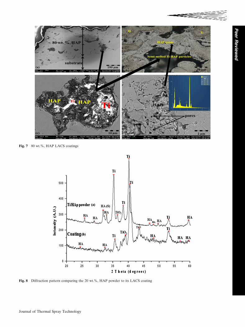
Fig. 7 80 wt.%, HAP LACS coatings
Fig. 8 Diffraction pattern comparing the 20 wt.%, HAP powder to its LACS coating
Journal of Thermal Spray Technology
Peer
Revie
wed
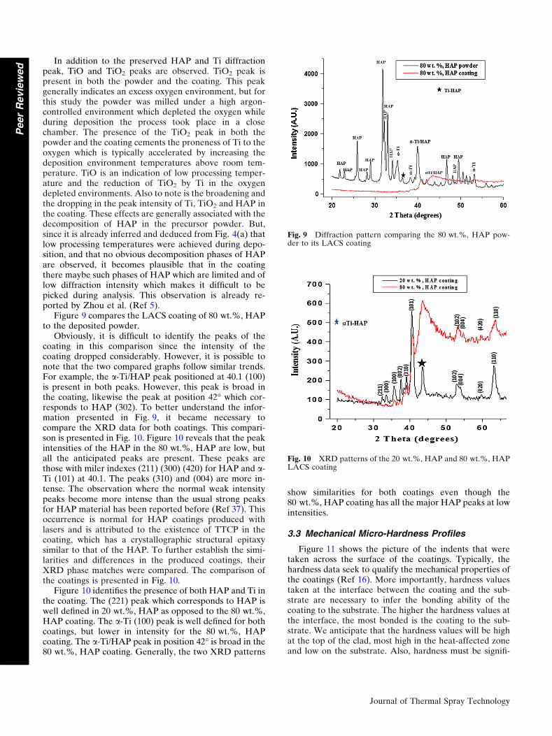
In addition to the preserved HAP and Ti diffractionpeak, TiO and TiO2 peaks are observed. TiO2 peak ispresent in both the powder and the coating. This peakgenerally indicates an excess oxygen environment, but forthis study the powder was milled under a high argon-controlled environment which depleted the oxygen whileduring deposition the process took place in a closechamber. The presence of the TiO2 peak in both thepowder and the coating cements the proneness of Ti to theoxygen which is typically accelerated by increasing thedeposition environment temperatures above room tem-perature. TiO is an indication of low processing temper-ature and the reduction of TiO2 by Ti in the oxygendepleted environments. Also to note is the broadening andthe dropping in the peak intensity of Ti, TiO2 and HAP inthe coating. These effects are generally associated with thedecomposition of HAP in the precursor powder. But,since it is already inferred and deduced from Fig. 4(a) thatlow processing temperatures were achieved during depo-sition, and that no obvious decomposition phases of HAPare observed, it becomes plausible that in the coatingthere maybe such phases of HAP which are limited and oflow diffraction intensity which makes it difficult to bepicked during analysis. This observation is already re-ported by Zhou et al. (Ref 5).
Figure 9 compares the LACS coating of 80 wt.%, HAPto the deposited powder.
Obviously, it is difficult to identify the peaks of thecoating in this comparison since the intensity of thecoating dropped considerably. However, it is possible tonote that the two compared graphs follow similar trends.For example, the a-Ti/HAP peak positioned at 40.1 (100)is present in both peaks. However, this peak is broad inthe coating, likewise the peak at position 42� which cor-responds to HAP (302). To better understand the infor-mation presented in Fig. 9, it became necessary tocompare the XRD data for both coatings. This compari-son is presented in Fig. 10. Figure 10 reveals that the peakintensities of the HAP in the 80 wt.%, HAP are low, butall the anticipated peaks are present. These peaks arethose with miler indexes (211) (300) (420) for HAP and a-Ti (101) at 40.1. The peaks (310) and (004) are more in-tense. The observation where the normal weak intensitypeaks become more intense than the usual strong peaksfor HAP material has been reported before (Ref 37). Thisoccurrence is normal for HAP coatings produced withlasers and is attributed to the existence of TTCP in thecoating, which has a crystallographic structural epitaxysimilar to that of the HAP. To further establish the simi-larities and differences in the produced coatings, theirXRD phase matches were compared. The comparison ofthe coatings is presented in Fig. 10.
Figure 10 identifies the presence of both HAP and Ti inthe coating. The (221) peak which corresponds to HAP iswell defined in 20 wt.%, HAP as opposed to the 80 wt.%,HAP coating. The a-Ti (100) peak is well defined for bothcoatings, but lower in intensity for the 80 wt.%, HAPcoating. The a-Ti/HAP peak in position 42� is broad in the80 wt.%, HAP coating. Generally, the two XRD patterns
show similarities for both coatings even though the80 wt.%, HAP coating has all the major HAP peaks at lowintensities.
3.3 Mechanical Micro-Hardness Profiles
Figure 11 shows the picture of the indents that weretaken across the surface of the coatings. Typically, thehardness data seek to qualify the mechanical properties ofthe coatings (Ref 16). More importantly, hardness valuestaken at the interface between the coating and the sub-strate are necessary to infer the bonding ability of thecoating to the substrate. The higher the hardness values atthe interface, the most bonded is the coating to the sub-strate. We anticipate that the hardness values will be highat the top of the clad, most high in the heat-affected zoneand low on the substrate. Also, hardness must be signifi-
Fig. 9 Diffraction pattern comparing the 80 wt.%, HAP pow-der to its LACS coating
Fig. 10 XRD patterns of the 20 wt.%, HAP and 80 wt.%, HAPLACS coating
Journal of Thermal Spray Technology
Peer
Revie
wed
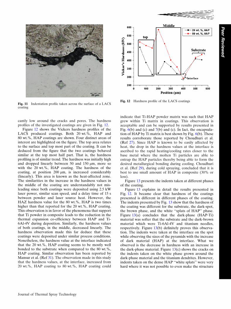
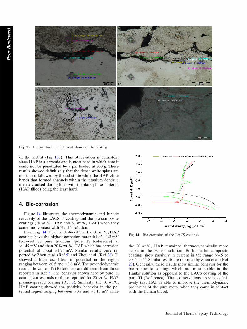
cantly low around the cracks and pores. The hardnessprofiles of the investigated coatings are given in Fig. 12.
Figure 12 shows the Vickers hardness profiles of theLACS produced coatings. Both 20 wt.%, HAP and80 wt.%, HAP coatings are shown. Four distinct areas ofinterest are highlighted on the figure. The top area relatesto the surface and top most part of the coating. It can bededuced from the figure that the two coatings behavedsimilar at the top most half part. That is, the hardnessprofiling is of similar trend. The hardness was initially highand dropped linearly between 50 and 150 lm, more sowith the 20 wt.%, HAP coating. The hardness of thecoating, at position 200 lm, is increased considerably(linearly). This area is known as the heat-affected zone.The similarities in the increase in the hardness values inthe middle of the coating are understandably not mis-leading since both coatings were deposited using 2.5 kWlaser power, similar scan speed, and a delay time of 15 sbetween powder and laser source heat. However, theHAZ hardness value for the 80 wt.%, HAP is two timeshigher than that reported for the 20 wt.%, HAP coating.This observation is in favor of the phenomena that supportthat Ti powder in composite leads to the reduction in thethermal expansion co-efficiency between HAP and Ti-6Al-4V during deposition. Similarly, the hardness valuesof both coatings, in the middle, decreased linearly. Thehardness observation made this far deduce that thesecoatings were deposited under similar process conditions.Nonetheless, the hardness value at the interface indicatedthat the 20 wt.%, HAP coating seems to be mostly wellbonded to the substrate when compared to the 80 wt.%,HAP coating. Similar observation has been reported byMansur et al. (Ref 31). The observation made in this studythat the hardness values, at the interface, increased from20 wt.%, HAP coating to 80 wt.%, HAP coating could
indicate that Ti-HAP powder matrix was such that HAPgrew within Ti matrix in coatings. This observation isacceptable and can be supported by results presented inFig. 6(b) and (c) and 7(b) and (c). In fact, the encapsula-tion of HAP by Ti matrix is best shown by Fig. 6(b). Theseresults corroborate those reported by Choudhuri et al.(Ref 27). Since HAP is known to be easily affected byheat, the drop in the hardness values at the interface isascribed to the rapid heating/cooling rates closer to thebase metal where the molten Ti particles are able toentrap the HAP particles thereby being able to form thedesired metallurgical bonding during cooling. Choudhuriet al. (Ref 29), during cold spraying, concluded that it isbest to use small amount of HAP in composite (30% orless).
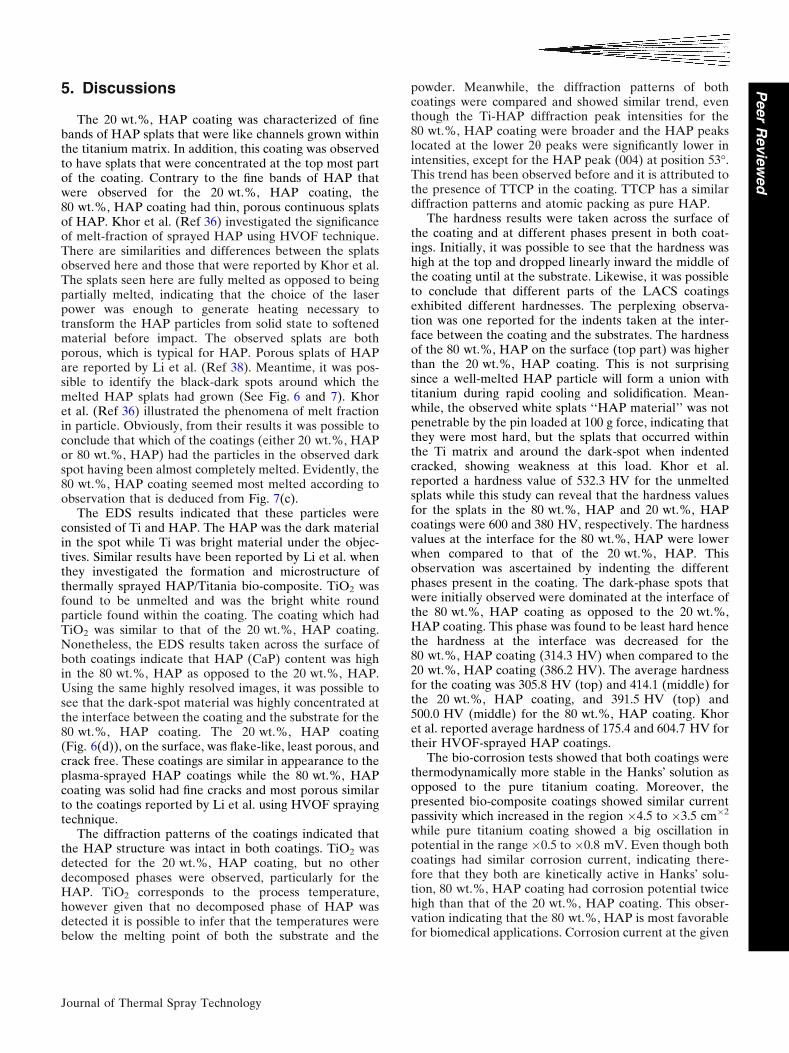
Figure 13 presents the indents taken at different phasesof the coating.
Figure 13 explains in detail the results presented inFig. 12. It became clear that hardness of the coatingspresented is different in different phases of the coating.The indents presented by Fig. 13 show that the hardness ofthe coating was different for the substrate, the dark-spot,the brown phase, and the white ‘‘splats of HAP’’ phase.Figure 13(a) concludes that the dark-phase (HAP-Ti)material was softer that the substrate and the dark-brownmaterial which were Ti-6Al-4V and titanium needles,respectively. Figure 13(b) definitely proves this observa-tion. The indents were taken at the interface on the spotwhile observing the sizes of the pyramids with the increaseof dark material (HAP) at the interface. What weobserved is the decrease in hardness with an increase inthe dark-phase material. Figure 13(c) shows the cracks onthe indents taken on the white phase grown around thedark-phase material and the titanium dendrites. However,indents taken on the dense HAP ‘‘white splats’’ were veryhard where it was not possible to even make the structure
Fig. 11 Indentation profile taken across the surface of a LACScoating
Fig. 12 Hardness profile of the LACS coatings
Journal of Thermal Spray Technology
Peer
Revie
wed
of the indent (Fig. 13d). This observation is consistentsince HAP is a ceramic and is most hard in which case itcould not be penetrated by a pin loaded at 300 g. Theseresults showed definitively that the dense white splats aremost hard followed by the substrate while the HAP whitebands that formed channels within the titanium dendritematrix cracked during load with the dark-phase material(HAP filled) being the least hard.
4. Bio-corrosion
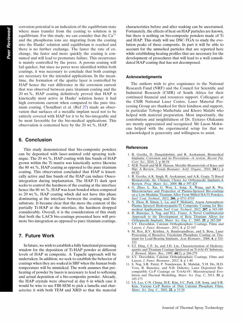
Figure 14 illustrates the thermodynamic and kineticreactivity of the LACS Ti coating and the bio-compositecoatings (20 wt.%, HAP and 80 wt.%, HAP) when theycome into contact with Hank�s solution.
From Fig. 14, it can be deduced that the 80 wt.%, HAPcoatings have the highest corrosion potential of �1.3 mVfollowed by pure titanium (pure Ti Reference) at�1.45 mV and then 20% wt.%, HAP which has corrosionpotential of about �1.75 mV. Similar results were re-ported by Zhou et al. (Ref 5) and Zhou et al. (Ref 28). Tishowed a huge oscillation in potential in the regionranging between �0.5 and �0.8 mV. The potentiodynamicresults shown for Ti (Reference) are different from thosereported in Ref 5. The behavior shown here by pure Ticoating corresponds to those reported for 20 wt.%, HAPplasma-sprayed coating (Ref 5). Similarly, the 80 wt.%,HAP coating showed the passivity behavior in the po-tential region ranging between �0.3 and �0.15 mV while
the 20 wt.%, HAP remained thermodynamically morestable in the Hanks� solution. Both the bio-compositecoatings show passivity in current in the range �4.5 to�3.5 cm�2. Similar results are reported by Zhou et al. (Ref28). Generally, these results show similar behavior for thebio-composite coatings which are most stable in theHanks� solution as opposed to the LACS coating of thepure Ti (Reference). These observations proving defini-tively that HAP is able to improve the thermodynamicproperties of the pure metal when they come in contactwith the human blood.
Fig. 13 Indents taken at different phases of the coating
Fig. 14 Bio-corrosion of the LACS coatings
Journal of Thermal Spray Technology
Peer
Revie
wed
5. Discussions
The 20 wt.%, HAP coating was characterized of finebands of HAP splats that were like channels grown withinthe titanium matrix. In addition, this coating was observedto have splats that were concentrated at the top most partof the coating. Contrary to the fine bands of HAP thatwere observed for the 20 wt.%, HAP coating, the80 wt.%, HAP coating had thin, porous continuous splatsof HAP. Khor et al. (Ref 36) investigated the significanceof melt-fraction of sprayed HAP using HVOF technique.There are similarities and differences between the splatsobserved here and those that were reported by Khor et al.The splats seen here are fully melted as opposed to beingpartially melted, indicating that the choice of the laserpower was enough to generate heating necessary totransform the HAP particles from solid state to softenedmaterial before impact. The observed splats are bothporous, which is typical for HAP. Porous splats of HAPare reported by Li et al. (Ref 38). Meantime, it was pos-sible to identify the black-dark spots around which themelted HAP splats had grown (See Fig. 6 and 7). Khoret al. (Ref 36) illustrated the phenomena of melt fractionin particle. Obviously, from their results it was possible toconclude that which of the coatings (either 20 wt.%, HAPor 80 wt.%, HAP) had the particles in the observed darkspot having been almost completely melted. Evidently, the80 wt.%, HAP coating seemed most melted according toobservation that is deduced from Fig. 7(c).
The EDS results indicated that these particles wereconsisted of Ti and HAP. The HAP was the dark materialin the spot while Ti was bright material under the objec-tives. Similar results have been reported by Li et al. whenthey investigated the formation and microstructure ofthermally sprayed HAP/Titania bio-composite. TiO2 wasfound to be unmelted and was the bright white roundparticle found within the coating. The coating which hadTiO2 was similar to that of the 20 wt.%, HAP coating.Nonetheless, the EDS results taken across the surface ofboth coatings indicate that HAP (CaP) content was highin the 80 wt.%, HAP as opposed to the 20 wt.%, HAP.Using the same highly resolved images, it was possible tosee that the dark-spot material was highly concentrated atthe interface between the coating and the substrate for the80 wt.%, HAP coating. The 20 wt.%, HAP coating(Fig. 6(d)), on the surface, was flake-like, least porous, andcrack free. These coatings are similar in appearance to theplasma-sprayed HAP coatings while the 80 wt.%, HAPcoating was solid had fine cracks and most porous similarto the coatings reported by Li et al. using HVOF sprayingtechnique.
The diffraction patterns of the coatings indicated thatthe HAP structure was intact in both coatings. TiO2 wasdetected for the 20 wt.%, HAP coating, but no otherdecomposed phases were observed, particularly for theHAP. TiO2 corresponds to the process temperature,however given that no decomposed phase of HAP wasdetected it is possible to infer that the temperatures werebelow the melting point of both the substrate and the
powder. Meanwhile, the diffraction patterns of bothcoatings were compared and showed similar trend, eventhough the Ti-HAP diffraction peak intensities for the80 wt.%, HAP coating were broader and the HAP peakslocated at the lower 2h peaks were significantly lower inintensities, except for the HAP peak (004) at position 53�.This trend has been observed before and it is attributed tothe presence of TTCP in the coating. TTCP has a similardiffraction patterns and atomic packing as pure HAP.
The hardness results were taken across the surface ofthe coating and at different phases present in both coat-ings. Initially, it was possible to see that the hardness washigh at the top and dropped linearly inward the middle ofthe coating until at the substrate. Likewise, it was possibleto conclude that different parts of the LACS coatingsexhibited different hardnesses. The perplexing observa-tion was one reported for the indents taken at the inter-face between the coating and the substrates. The hardnessof the 80 wt.%, HAP on the surface (top part) was higherthan the 20 wt.%, HAP coating. This is not surprisingsince a well-melted HAP particle will form a union withtitanium during rapid cooling and solidification. Mean-while, the observed white splats ‘‘HAP material’’ was notpenetrable by the pin loaded at 100 g force, indicating thatthey were most hard, but the splats that occurred withinthe Ti matrix and around the dark-spot when indentedcracked, showing weakness at this load. Khor et al.reported a hardness value of 532.3 HV for the unmeltedsplats while this study can reveal that the hardness valuesfor the splats in the 80 wt.%, HAP and 20 wt.%, HAPcoatings were 600 and 380 HV, respectively. The hardnessvalues at the interface for the 80 wt.%, HAP were lowerwhen compared to that of the 20 wt.%, HAP. Thisobservation was ascertained by indenting the differentphases present in the coating. The dark-phase spots thatwere initially observed were dominated at the interface ofthe 80 wt.%, HAP coating as opposed to the 20 wt.%,HAP coating. This phase was found to be least hard hencethe hardness at the interface was decreased for the80 wt.%, HAP coating (314.3 HV) when compared to the20 wt.%, HAP coating (386.2 HV). The average hardnessfor the coating was 305.8 HV (top) and 414.1 (middle) forthe 20 wt.%, HAP coating, and 391.5 HV (top) and500.0 HV (middle) for the 80 wt.%, HAP coating. Khoret al. reported average hardness of 175.4 and 604.7 HV fortheir HVOF-sprayed HAP coatings.
The bio-corrosion tests showed that both coatings werethermodynamically more stable in the Hanks� solution asopposed to the pure titanium coating. Moreover, thepresented bio-composite coatings showed similar currentpassivity which increased in the region �4.5 to �3.5 cm�2
while pure titanium coating showed a big oscillation inpotential in the range �0.5 to �0.8 mV. Even though bothcoatings had similar corrosion current, indicating there-fore that they both are kinetically active in Hanks� solu-tion, 80 wt.%, HAP coating had corrosion potential twicehigh than that of the 20 wt.%, HAP coating. This obser-vation indicating that the 80 wt.%, HAP is most favorablefor biomedical applications. Corrosion current at the given
Journal of Thermal Spray Technology
Peer
Revie
wed
corrosion potential is an indication of the equilibrium statewhere mass transfer from the coating to solution is inequilibrium. For this study, we can consider that the Ca2+
and the phosphorus ions are migrating from the coatinginto the Hanks� solution until equilibrium is reached andthere is no further exchange. The faster the rate of ex-change, the faster and more quickly the coating is con-sumed and will lead to premature failure. This occurrenceis mainly controlled by the pores. A porous coating willfail quicker, but since no pores were identified within bothcoatings, it was necessary to conclude that both coatingsare necessary for the intended applications. In the mean-time, the formation of the apatite layer is controlled byHAP hence the vast difference in the corrosion currentthat was observed between pure titanium coating and the20 wt.%, HAP coating definitively proved that HAP iskinetically most active in Hanks� solution hence it hadhigh corrosions current when compared to the pure tita-nium coating. Choudhuri et al. (Ref 27) made an obser-vation that surfaces of a metallic implant need not to beentirely covered with HAP for it to be bio-integrable andbe most favorable for the bio-medical applications. Thisobservation is cemented here by the 20 wt.%, HAP.
6. Conclusion
This study demonstrated that bio-composite powderscan be deposited with laser-assisted cold spraying tech-nique. The 20 wt.%, HAP coating with fine bands of HAPgrown within the Ti matrix was kinetically active likewisethe 80 wt.%, HAP coating as opposed to the pure titaniumcoating. This observation concluded that HAP is kineti-cally active and fine bands of the HAP can induce Osseo-integration during implantation. The HAP-Ti dark spotseeks to control the hardness of the coating at the interfacehence the 80 wt.%, HAP was least bonded when comparedto 20 wt.%, HAP coating which did not have this phasedominating at the interface between the coating and thesubstrate. It became clear that the more the content of thepartially Ti-HAP at the interface, the hardness droppedconsiderably. Overall, it is the consideration of this studythat both the LACS bio-coatings presented here will pro-mote bio-integration as opposed to pure titanium coatings.
7. Future Work
In future, we wish to establish a fully functional processingwindow for the deposition of Ti-HAP powder at differentlevels of HAP in composite. A Taguchi approach will beundertaken. In addition, we seek to establish the behavior ofcoatings when they are soaked in SBF when the human bodytemperature will be mimicked. The work assumes that pre-heating of powder by lasers is necessary to lead to softeningand actual deposition of a bio-composite powder. Already,the HAP crystals were observed at day 6 in which case itwould be wise to use FIB-SEM to pick a lamella and char-acterize it with both TEM and XRD so that the material
characteristics before and after soaking can be ascertained.Fortunately, the effects of heat on HAP particles are known,but there is nothing on bio-composite powders made of Tiand HAP. This study will use DSC-TGA to study the evo-lution peaks of these composite. In part it will be able toaccount for the unmelted particles that are reported herewhile establishing heating profiles that are necessary for thedevelopment of procedures that will lead to a well consoli-dated HAP coating that has not decomposed.
Acknowledgments
The authors wish to give cognisance to the NationalResearch Fund (NRF) and the Council for Scientific andIndustrial Research (CSIR) of South Africa for theircontinued financial and resources support. Colleagues atthe CSIR National Laser Centre, Laser Material Pro-cessing Group are thanked for their kindness and support,in particular Tebogo Mathebula and Khoro Malabi whohelped with material preparation. Most importantly, thecontribution and insightfulness of Dr. Eyitayo Olakanmiare mostly appreciated and recognized. Mr Lucas Mokw-ena helped with the experimental setup for that weacknowledged is generosity and willingness to assist.
References
1. R. Geetha, D. Durgalakshmi, and R. Asokamani, BiomedicalImplants: Corrosion and its Prevention—A review, Recent Pat.Corr. Sci., 2010, 2, p 40-54
2. M.B. Nasab and M.R. Hassan, Metallic Biomaterials of Knee andHip: A Review, Trends Biomater. Artif. Organs., 2010, 24(1), p69-82
3. R. Geetha, A.K. Singh, R. Asokamani, and A.K. Gogia, Ti BasedBiomaterials, the Ultimate Choice for Orthopaedic Implants-AReview, Prog. Mater. Sci., 2009, 54, p 397-425
4. G. Zhao, L. Xia, G. Wen, L. Song, X. Wang, and K. Wu,Microstructure and Properties of Plasma-Sprayed Bio-coatingson a Low-Modulus Titanium Alloy From Milled HA/Ti Powders,Surf. Coat. Technol., 2012, 206, p 4711-4719
5. X. Zhou, R. Siman, L. Lu, and P. Mohanty, Argon AtmosphericPlasma Sprayed Hydroxyapatite/Ti Composite Coating for Bio-medical Applications, Surf. Coat. Technol., 2012, 207, p 343-349
6. R. Banerjee, S. Nag, and H.L. Fraser, A Novel CombinatorialApproach to the Development of Beta Titanium Alloys forOrthopaedic Implants, Mater. Sci. Eng. C., 2005, 25, p 282-289
7. S.V. Dorozhkin, Calcium Orthophosphate Coatings, Films andLayers, J. Funct. Biomater., 2012, 1, p 22-107
8. M. Roy, B.V. Krishna, A. Bandyopadhyay, and S. Bose, LaserProcessing of Bioactive Tricalcium Phosphate Coating on Tita-nium for Load-Bearing Implants, Acta Biomater., 2008, 4, p 324-333
9. S.J. Ding, C.P. Ju, and J.H. Lin, Characterization of Hydroxy-apatite and Titanium Coatings Sputtered on Ti-6Al-4V Substrate,J. Biomed. Mater. Res., 1999, 44(3), p 266-279
10. S.V. Dorozhkin, Calcium Orthophosphate Coatings, Films andLayers, J. Funct. Biomater., 2012, 1, p 1-40
11. S. Nag, S.R. Paital, P. Nandawana, K. Mahdak, Y.H. Ho, H.D.Vora, R. Banerjee, and N.B. Dahotre, Laser Deposited Bio-compatible Ca-P Coatings on Ti-6Al-4V: Microstructural Evo-lution and Thermal Modelling, Mater. Sci. Eng. C, 2013, 33, p165-173
12. I-S. Lee, C-N. Chang, H-E. Kim, J-C. Park, J.H. Song, and S-R.Kim, Various Ca/P Ratios of Thin Calcium Phosphate Films,Mater. Sci. Eng. C., 2002, 22, p 15-20
Journal of Thermal Spray Technology
Peer
Revie
wed
13. M. Tlotleng, E. Akinlabi, M. Shukla, and S. Pityana, Micro-structures, Hardness and Bioactivity of Hydroxyapatite CoatingsDeposited by Direct Laser Melting Process, J. Mater. Sci. Eng. C,2014, 43, p 189-198
14. D. Liu, K. Savino, and M.Z. Yates, Coating of HydroxyapatiteFilms on Metal Substrates by Seeded Hydrothermal Deposition,Surf. Coat. Technol., 2011, 205, p 3975-3986
15. R. Sultana, J. Yang, and X. Hu, Deposition of Micro-PorousHydroxyapatite/Tri-Calcium Phosphate Coating on Zirconia-Based Substrate, J. Am. Ceram. Soc., 2012, 95(4), p 1212-1215
16. G.J. Cheng, D. Pirzada, M. Cai, P. Mohanty, and A. Bandyopad-hyay, Biocermic Coating of Hydroxyapatite on Titanium Substratewith Nd:YAG Laser, Mater. Sci. Eng. C., 2005, 25, p 541-547
17. D.G. Wang, C.Z. Chen, J. Ma, and G. Zhang, In Situ Synthesis ofHydroxyapatite Coating by Laser Cladding, Colloids Surf., B.,2008, 66, p 155-162
18. S.V. Dorozhkin, Calcium Orthophosphate Coatings, Films andLayers, Prog. Biomater., 2010, 1(1), p 1-40
19. M. Roy, A. Bandyopadhyay, and S. Bose, Induction PlasmaSprayed Nano Hydroxyapatite Coatings on Titanium for Ortho-paedic and Dental Implants, Surf. Coat. Technol., 2008, 205(8-9),p 2785-2792
20. D.J. Blackwood and K.H.W. Seah, Electrochemical CathodicDeposition of Hydroxyapatite: Improvements in Adhesion andCrystallinity, Mater. Sci. Eng. C, 2009, 29, p 1233-1238
21. D.-M. Liu, Q. Yang, and T. Troczynski, Sol-Gel HydroxyapatiteCoatings on Stainless Steel Substrates, Biomaterials, 2002, 23, p691-698
22. V. Kokenyesi, I. Popovich, M. Kikineshi, L. Daroczi, D. Beke, Y.Sharkany, and C.S. Hegedus, Preparation of Calcium PhosphateCoatings on Titanium by Pulse Nd:YAG Laser Processing, Opto-Electro. Adv. Mater. Rapid. Commun., 2007, 1(4), p 171-175
23. R.A. Ismail, E.T. Salim, and W.K. Hamoudi, Characterization ofNanostructured Hydroxyapatite Prepared by Nd:YAG LaserDeposition, Mater. Sci. Eng. C., 2013, 33, p 47-52
24. D. Wang, C. Chen, J. Ma, and T. Lei, Microstructure of YttricCalcium Phosphate Bioceramic Coatings Synthesized by LaserCladding, Appl. Surf. Sci., 2007, 253, p 4016-4020
25. C.S. Chien, T.J. Han, T.F. Hong, T.Y. Kuo, and T.Y. Liao, Ef-fects of Different Binders on Microstructure and Phase Compo-sition of Hydroxyapatite Nd-YAG Laser Clad Coatings, Mater.Trans., 2009, 50(12), p 2852-2857
26. K.A. Gross and C.C. Berndt, Thermal Processing of Hydroxy-apatite for Coating Production, J. Biomed. Mater. Res., 1998,39(4), p 580-587
27. A. Choudhuri, P.S. Mohaunty, and J. Karthikeyan, Bio-ceramicComposite Coatings by Cold Spray Technology, ThermalSpraying, 2009, p 391-396
28. X. Zhou and P. Mohanty, Electrochemical Behaviour of ColdSprayed Hydroxyapatite/Titanium Composite in Hanks� Solution,Electrochim. Acta, 2012, 65, p 134-140
29. M.R. Mansur, J. Wang, and C.C. Berndt, Microstructure, Com-position and Hardness of Laser-Assisted Hydroxyapatite and Ti-6Al-4V Composite Coatings, Surf. Coat. Technol., 2013, 232, p482-488
30. C.S. Chien, T.F. Hong, T.J. Han, T.Y. Kuo, and T.Y. Liao, Ef-fects of Different Binders on Microstructure and Phase Compo-sition of Hydroxyapatite Nd-YAG Laser Clad Coatings, Appl.Surf. Sci., 2011, 257(6), p 2387-2393
31. M. Bray, A. Cockburn, and W. O�Neill, The Laser-Assisted ColdSprayed Process and Deposition Characterisation, Surf. Coat.Technol., 2009, 203, p 2851-2857
32. E.O. Olakanmi, M. Tlotleng, C. Meacock, S. Pityana, and M.Doyoyo, Deposition Mechanism and Microstructure of Laser-Assisted-Cold-Sprayed (LACS) Al-12 wt.%Si Coatings: Effectsof Laser Power, JOM, 2013, 65(6), p 776-783
33. R. Lupoi, M. Sparkes, A. Cockburn, and W. O�Neille, HighSpeed Titanium Coatings by Supersonic Laser Deposition, Mater.Lett., 2011, 65, p 3205-3207
34. F.J. Brodmann, Cold Spray Process Parameters: Powders, TheCold Spray Materials Deposition Process, V.K. Champagne, Ed.,Woodhead Publishing, 2007, p 105-116
35. E.O. Olakanmi and M. Doyoyo, Laser-Assisted Cold-SprayedCorrosion-and Wear-Resistant Coatings: A Review, J. Therm.Spray Techno, 2014, 23(5), p 765-785
36. K.A. Khor, H. Li, and P. Cheang, Significance of Melt-Fraction inHVOF Sprayed Hydroxyapatite Particles, Splats and Coatings.Biomaterials, 2004, 25(7-8), p 1177-1186
37. W.E. Brown and E.F. Epstein, Crystallography of TetracalciumPhosphate, J. Res. Nat. Bureau Std. A. Phys. Chem, 1965, 69(6), p547-551
38. H. Li, K.A. Khor, and P. Cheang, Thermal Sprayed Hydroxy-apatite Splats: Nanostructures Pore Formation Mechanisms andTEM Characterisation, Biomaterials, 2004, 25, p 3463-3471
Journal of Thermal Spray Technology
Peer
Revie
wed
Related Documents