METHODOLOGY TO CALCULATE THE FRACTURE GRADIENT IN A TECTONICALLY ACTIVE ZONE CT&F - Ciencia, Tecnología y Futuro - Vol. 3 Núm. 5 Dic. 2009 53 METHODOLOGY TO CALCULATE THE FRACTURE GRADIENT IN A TECTONICALLY ACTIVE ZONE: AN APPLICATION IN COLOMBIAN FOOTHILLS Oscar-M. Contreras¹*, Reinel Corzo 2 , Néstor-F. Saavedra 3 and Zuly-H. Calderón 4 1 Convenio Ecopetrol S.A. - Universidad Industrial de Santander, UIS, Bucaramanga, Santander, Colombia 2, 3 Ecopetrol S.A. -Instituto Colombiano de Petróleo, A.A. 4185 Bucaramanga, Santander, Colombia 4 Universidad Industrial de Santander, Facultad de Ingenierías Físico-Químicas, Bucaramanga, Santander, Colombia e-mail: [email protected] (Received April 30, 2008; Accepted September 16, 2009) F racture gradient estimates are fundamental to predict the pressure required to hydraulically fracture a forma- tion. The main objective of this work is to propose a new methodology to calculate a fracture gradient value based on the application of two new different methods: Pseudo-Overburden Stress Method and Effective Stress Method. These new methods were obtained by modifying and improving two approaches proposed in the literature, putting them in a logic and systematic order, making possible their application to onshore wells, incorporating a new function to calculate calibration constants with the less associated uncertainty, and broadening their scope of application to involve formations at depths different from the initial calibration depths by including a new sub-process. Furthermore, they involve input field parameters: fracture gradient, vertical stress and pore pressure, which describe the geomechanical conditions of the formation. This methodology is validated in the Mirador Superior and Barco formations in Colombian Foothills. Results are compared to values obtained from Minifrac TM field data. Application of this methodology allows prediction of reliable fracture gradient values. Keywords: hydraulic fracturing, fracture gradient, foothills, Colombia, Mirador Superior, Barco, Effective Stress Method, Pseudo-Overburden Stress Method. Ciencia, Tecnología y Futuro * Now with the University of Calgary. To whom correspondence may be addressed.

Welcome message from author
This document is posted to help you gain knowledge. Please leave a comment to let me know what you think about it! Share it to your friends and learn new things together.
Transcript
METHODOLOGY TO CALCULATE THE FRACTURE GRADIENT IN A TECTONICALLY ACTIVE ZONE
CT&F - Ciencia, Tecnología y Futuro - Vol. 3 Núm. 5 Dic. 2009 53
METHODOLOGY TO CALCULATE THE FRACTURE GRADIENT IN
A TECTONICALLY ACTIVE ZONE: AN APPLICATION IN COLOMBIAN
FOOTHILLSOscar-M. Contreras¹*, Reinel Corzo2, Néstor-F. Saavedra3 and Zuly-H. Calderón4
1 Convenio Ecopetrol S.A. - Universidad Industrial de Santander, UIS, Bucaramanga, Santander, Colombia2, 3 Ecopetrol S.A. -Instituto Colombiano de Petróleo, A.A. 4185 Bucaramanga, Santander, Colombia
4 Universidad Industrial de Santander, Facultad de Ingenierías Físico-Químicas, Bucaramanga, Santander, Colombia
e-mail: [email protected]
(Received April 30, 2008; Accepted September 16, 2009)
Fracture gradient estimates are fundamental to predict the pressure required to hydraulically fracture a forma-tion. The main objective of this work is to propose a new methodology to calculate a fracture gradient value based on the application of two new different methods: Pseudo-Overburden Stress Method and Effective Stress
Method. These new methods were obtained by modifying and improving two approaches proposed in the literature, putting them in a logic and systematic order, making possible their application to onshore wells, incorporating a new function to calculate calibration constants with the less associated uncertainty, and broadening their scope of application to involve formations at depths different from the initial calibration depths by including a new sub-process. Furthermore, they involve input field parameters: fracture gradient, vertical stress and pore pressure, which describe the geomechanical conditions of the formation. This methodology is validated in the Mirador Superior and Barco formations in Colombian Foothills. Results are compared to values obtained from MinifracTM field data. Application of this methodology allows prediction of reliable fracture gradient values.
Keywords: hydraulic fracturing, fracture gradient, foothills, Colombia, Mirador Superior, Barco, Effective Stress Method, Pseudo-Overburden Stress Method.
Ciencia, Tecnología y Futuro
* Now with the University of Calgary. To whom correspondence may be addressed.
CT&F - Ciencia, Tecnología y Futuro - Vol. 3 Núm. 5 Dic. 2009
OSCAR-M. CONTRERAS et al
54
Estimaciones del gradiente de fractura son fundamentales en la predicción de la presión requerida para fracturar una formación hidráulicamente. El principal objetivo de este trabajo consiste en proponer una nueva metodología para calcular un valor de gradiente de fractura basado en la
aplicación de dos nuevos y diferentes métodos: Pseudo-Overburden Stress Method y Effective Stress Method. Estos nuevos métodos fueron obtenidos modificando y mejorando dos métodos propuestos en la literatura, acondicionándolos en un orden lógico y sistemático, haciendo posible su aplicación a pozos onshore, incorporando una nueva función para calcular constantes de calibración con la menor incertidumbre asociada, y ampliando su campo de aplicación para involucrar formaciones a profundidades diferentes a las de la calibración inicial al incluir un nuevo sub-proceso. Adicionalmente, estos métodos incorporan parámetros de entrada como gradiente de fractura, esfuerzo vertical y presión de poro, los cuales describen las condiciones geomecánicas de la formación. Esta metodología es validada en las formaciones Mirador Superior y Barco en el Piedemonte Colombiano. Los resultados de esta metodología son comparados con los valores de obtenidos de pruebas MinifracTM. La aplicación de esta metodología permite la predicción de valores confiables de gradiente de fractura.
Palabras Clave: fracturamiento hidráulico, gradiente de fractura, Piedemonte, Colombia, Mirador Superior, Barco.
METHODOLOGY TO CALCULATE THE FRACTURE GRADIENT IN A TECTONICALLY ACTIVE ZONE
CT&F - Ciencia, Tecnología y Futuro - Vol. 3 Núm. 5 Dic. 2009 55
INTRODUCTION
Increasing the hydrocarbon production has been the essence over the last few years and, therefore, different strategies have been implemented to make reservoirs even more productive. One of the most effective stra-tegies is the hydraulic fracturing, a stimulation method involving fracturing the productive strata by injecting a
open with a propping agent, and the high permeability
wells that evidence near-wellbore damage (presence of a positive Skin) or in those wells in low permeability
formations. Usually, the service companies executing the hydraulic fracturing operation reports fracture gra-dients values based on ISIP data (Instantaneous Shut-In
tortuosity and perforation friction are not considered in this paper and, fracture gradient values are based on ISIP values.
Several publications (Salz, 1979; Anderson, R. A., Ingram, D. S., & Zanier, A. M. (1973). et al., 1973; Eaton, 1969; Zoback, 2007; Hubbert and Willis, 1956) have proposed different methods for calculating the fracture gradient value, all corresponding to direct prediction methods (correlations). Values obtained from applica-
gf Fracture gradient (psi/ft)Pf Formation fracture pressure (psi)D Formation depth (ft)øo Surface pseudo porosity (dimensionless) Kø Declination Pseudo porosity (1/ft)
pseudo Pseudo-Overburden stress (psi)Vertical stress (psi)
g Grain density (lb/ft3)
f
w Water density (lb/ft3
Dw Water depth (ft)g Gravity constant (ft/sec2)
f Fracture stress (psi)
p Pore pressure (psi)
v Vertical Stress (psi)K Stress ratio Constant (dimensionless)gf Fracture Gradient (psi/ft)gv Vertical stress gradient (psi/ft)gp Pore pressure gradient (psi/ft)
NOMENCLATURE

CT&F - Ciencia, Tecnología y Futuro - Vol. 3 Núm. 5 Dic. 2009
OSCAR-M. CONTRERAS et al
56
racteristics because they are purely correlative; this can result in erroneous calculation of the fracture gradient value and inappropriate selection of surface equipment.
to use methods that relate the fracture gradient calcula-
zones in order to ensure an explicit calibration of the calculation method, as presented in this work.
thodology for fracture gradient calculation involving two new methods: the Pseudo-Overburden Stress
of this methodology is to predict a fracture gradient value with the least uncertainty for the well of interest by selecting the greatest of the two fracture gradient values obtained from the two methods (this leads to a
adjusted according to the conditions prevailing during the prediction process.
mainly on the following criteria:
strata characteristics, leading to predictions with -
tions of the traditional methods.
-sure values of the offset wells used in calibration of
conditions of the formations of interest.
Input data such as Minifrac -mechanical parameters required by the methods (which are distinctive input data of the two involved
considered to be reliable values.
here is based on the method of Rocha and Bourgoyne
method, is applicable to wells without water columns (onshore wells), exhibits a logic and systematic order, incorporates a new function “Selection Kø and øo (1)” to calculate calibration constants with the less asso-ciated uncertainty, and includes a new sub-process “ME” which allows involving formations at depths different from the initial calibration depths.
contrast to the base method: is applied to non-over-pressured formations, exhibits a logic and systematic order, and incorporates a new sub-process “EE” which allows involving formations at depths different from the initial calibration depths.
-
Colombian Andean Foothills. Results were compared to the values obtained from Minifrac
THEORETICAL CONCEPTS
Fracture Gradient
that determines the necessary pressure to be applied to fracture the formation (Fjaer, Holt, Horsrud, Raaen & Risnes,1996):
to friction and hydrostatic pressure are the base to ob-tain the surface treatment pressure, and, therefore, the required hydraulic power.
Calculation of the Fracture Gradient by Field Tests
and Minifracfracture gradient.
Method of Rocha and Bourgoyne (1996)-
siders the depth of each well in presence of water column.
with the value of the two constants (Kø and øo)which characterize the target formation. Model development begins expressing the formation porosity as follows:
e
o
K D
(1)
(2)

METHODOLOGY TO CALCULATE THE FRACTURE GRADIENT IN A TECTONICALLY ACTIVE ZONE
CT&F - Ciencia, Tecnología y Futuro - Vol. 3 Núm. 5 Dic. 2009 57
integrating volumetric density in depth considering the
as follows:
Pseudo-Overburden stress corresponding to each well
one axis and the fracture stress values obtained from
corresponding to the constants Kø and øo for which the slope of the trend line obtained in the curve equals to
equal to the fracture stress.
Method of Brennan and Annis (1984)
presented as follows:
the effective fracture stress to the effective vertical stress for a set of calibration wells located in the vicinity of
If Equation 4 is divided by depth, the basic form of the equation becomes:
function of gradients:
Fracture gradient with application of the Equation 5can be predicted if a curve illustrating effective fracture
gradient vs. vertical effective stress gradient with a de-
to relate them is designed as follows:
Isolating the fracture gradient:
for the stress ratio constant by graphing the effective fracture gradients vs. effective vertical stress gradients of calibration wells and obtaining the slope of the
Equation 4. If
two effective stress values.
PROPOSED METHODOLOGY
gradient involves two new methods:
Pseudo-Overburden Stress MethodEffective Stress Method
methods proposed by Rocha and Bourgoyne (1996) and Brennan and Annis (1984) respectively.
One innovative fact considered by this proposed methodology is including a security factor by sele-cting the greatest fracture gradient value obtained after implementing the two new methods; this allows a more conservative operation design. Underestimating the fracture gradient value leads to an inappropriate surface
fact is reinforced by considering that many hydraulic
hydraulic power.
(3)
(4)
(5)
(6)
(7)
(8)
CT&F - Ciencia, Tecnología y Futuro - Vol. 3 Núm. 5 Dic. 2009
OSCAR-M. CONTRERAS et al
58
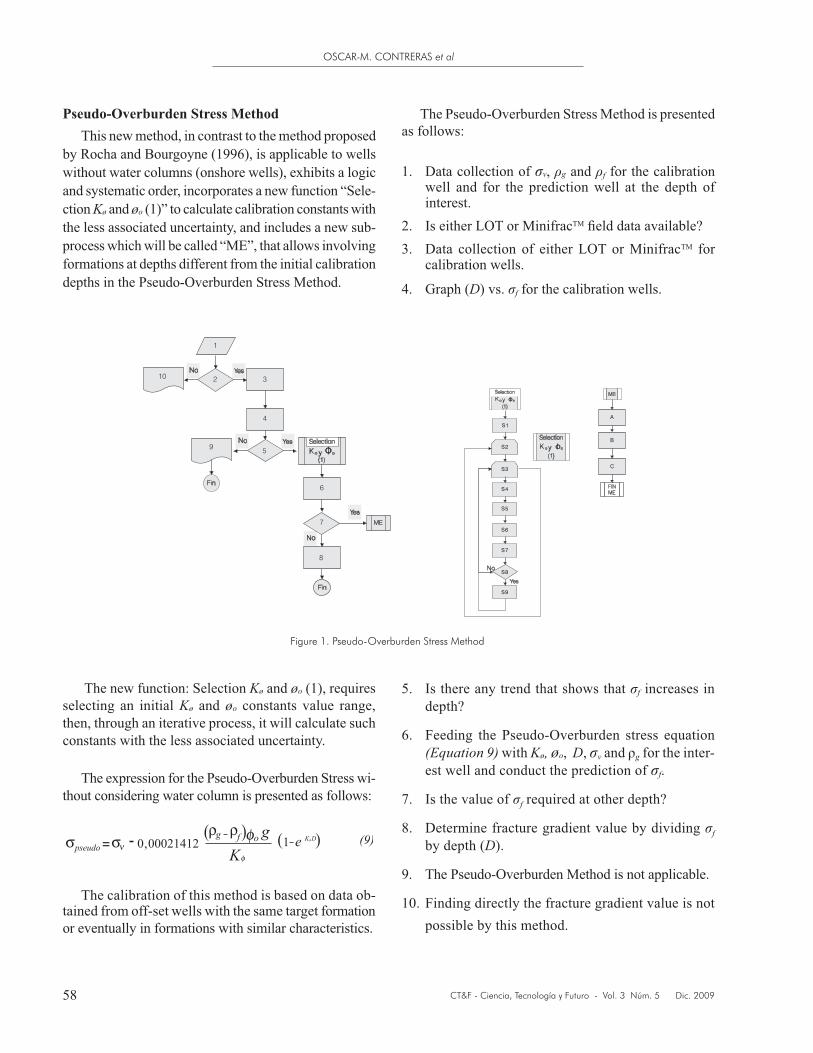
Pseudo-Overburden Stress Method
by Rocha and Bourgoyne (1996), is applicable to wells without water columns (onshore wells), exhibits a logic and systematic order, incorporates a new function “Sele-ction Kø and øo (1)” to calculate calibration constants with the less associated uncertainty, and includes a new sub-process which will be called “ME”, that allows involving formations at depths different from the initial calibration depths in the Pseudo-Overburden Stress Method.
Kø and øo (1), requires selecting an initial Kø and øo constants value range, then, through an iterative process, it will calculate such constants with the less associated uncertainty.
thout considering water column is presented as follows:
-tained from off-set wells with the same target formation or eventually in formations with similar characteristics.
as follows:
1. Data collection of , g and f for the calibration well and for the prediction well at the depth of interest.
2.3. for
calibration wells.
4. Graph (D) vs. f for the calibration wells.
Figure 1. Pseudo-Overburden Stress Method
5. Is there any trend that shows that f increases in
6. Feeding the Pseudo-Overburden stress equation (Equation 9) with Kø, øo, D, g for the inter-est well and conduct the prediction of f.
7. Is the value of f
8. Determine fracture gradient value by dividing f by depth (D).
9.
10. Finding directly the fracture gradient value is not possible by this method.

METHODOLOGY TO CALCULATE THE FRACTURE GRADIENT IN A TECTONICALLY ACTIVE ZONE
CT&F - Ciencia, Tecnología y Futuro - Vol. 3 Núm. 5 Dic. 2009 59
ME: Sub-process to calculate f at a different depth from the value used in the initial prediction.
A. Graph f vs. Depth (D) for the calibration wells and the well of interest at the corresponding depth.
B. Draw a trend line from the graph obtained on A and express fracture stress in function of depth.
C. Feed the correlation obtained on B with the depth at which the value of f f is desired.
Selection Kø and øo (1)S1. Select a range of values for the constants øo and
Kø, as: (øoi, øof) and (Køi, Køf), respectively, as well Kø
øo.S2. For Kø, between Køi and Køf, with Kø = Kø Kø,
complete S3.S3. For øo, between øoi and øof, with øo = øo øo,
complete from S4 to S9.S4. Generate a set of values where X set are the frac-
Overburden stress values (Equation 9).S5. Draw a trend line by the minimum square value
method and calculate its slope for the set of values
the evaluation of the line obtained on S5. In addi-ideal = X corresponding to the
unitary slope line is created.
ideal is calculated.
S9. Save the couple of values (Kø, øo).
Effective Stress Method
by Brennan and Annis (1984), is applied to non-over-pressured formations, exhibits a logic and systematic order, and incorporates a new sub-process which will be called “EE”, that allows involving formations at depths different from the initial calibration depths in the Effective Stress Method.
follows:
Figure 2. The Effective Stress Method
Where:1. Data collection of gp and (g - gp) for the calibra-
tion wells and for the prediction well at the depth of interest.
2.3. Data collection of f and gf for the calibration
wells.4. f - gp) and (g - gp) for each calibration
well.5. Obtain the value of K for each calibration well
(Equation 6).6. Graph K vs. depth (D).7. Is there uniform trend for the K value in depth (K8. Graph (gf - gp) vs. (g - gp) and determine the slope
which corresponds to the K value.9. Apply the Equation 5.10. It is not possible to apply the Equation 5.11. Graph (gf - gp) vs. (gv - gp) and draw a trend line. 12. Express the trend line as it is presented in the
Equation 7.
CT&F - Ciencia, Tecnología y Futuro - Vol. 3 Núm. 5 Dic. 2009
OSCAR-M. CONTRERAS et al
60
APPLICATION OF THE METHODOLOGY AND RESULTS
fracture gradient for Mirador Superior and Barco forma-
Calculation of the Fracture Gradient value from the Pseudo-Overburden Stress Method
-rior formation in FHC 7 well, 6 fracture gradient values
fracture gradient values will be used. Fracture gradient calculation for each formation will be conducted simul-taneously following the numbering system proposed:
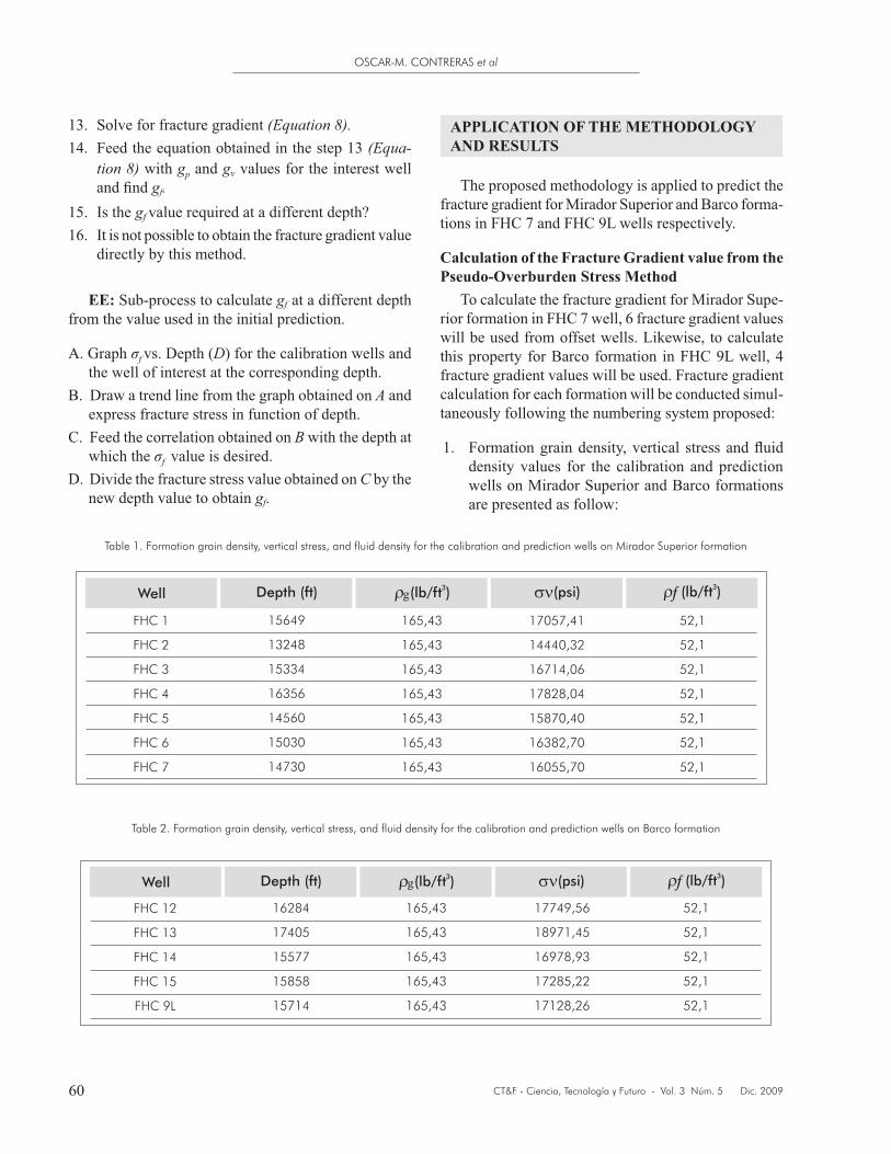
1.density values for the calibration and prediction wells on Mirador Superior and Barco formations are presented as follow:
13. Solve for fracture gradient (Equation 8).14. Feed the equation obtained in the step 13 (Equa-
tion 8) with gp and g values for the interest well gf.
15. Is the gf
16. It is not possible to obtain the fracture gradient value directly by this method.
EE: Sub-process to calculate gf at a different depth from the value used in the initial prediction.
A. Graph f vs. Depth (D) for the calibration wells and the well of interest at the corresponding depth.
B. Draw a trend line from the graph obtained on A and express fracture stress in function of depth.
C. Feed the correlation obtained on B with the depth at which the f value is desired.
D. Divide the fracture stress value obtained on C by the new depth value to obtain gf.
Table 1. Formation grain density, vertical stress, and fluid density for the calibration and prediction wells on Mirador Superior formation
Table 2. Formation grain density, vertical stress, and fluid density for the calibration and prediction wells on Barco formation
Well
Depth (ft)
g
3
(lb/ft )
(psi)
3
(lb/ft )
FHC 1
FHC 2
FHC 3
FHC 4
FHC 5
FHC 6
FHC 7
15649
13248
15334
16356
14560
15030
14730
165,43
165,43
165,43
165,43
165,43
165,43
165,43
17057,41
14440,32
16714,06
17828,04
15870,40
16382,70
16055,70
52,1
52,1
52,1
52,1
52,1
52,1
52,1
Well
Depth (ft)
g
3
(lb/ft )
(psi)
3
(lb/ft )
FHC 12
FHC 13
FHC 14
FHC 15
FHC 9L
16284
17405
15577
15858
15714
165,43
165,43
165,43
165,43
165,43
17749,56
18971,45
16978,93
17285,22
17128,26
52,1
52,1
52,1
52,1
52,1
METHODOLOGY TO CALCULATE THE FRACTURE GRADIENT IN A TECTONICALLY ACTIVE ZONE
CT&F - Ciencia, Tecnología y Futuro - Vol. 3 Núm. 5 Dic. 2009 61
2. Minifrac
data for calibration wells are collected.
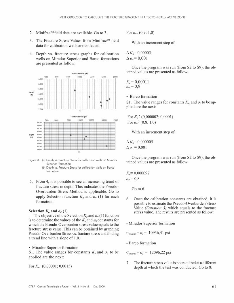
4. Depth vs. fracture stress graphs for calibration wells on Mirador Superior and Barco formations are presented as follow:
5. From 4, it is possible to see an increasing trend of
Overburden Stress Method is applicable. Go to apply Selection function Kø and øo (1) for each formation.
Selection Kø and øo (1)Kø and øo (1) function
is to determine the values of the Kø and øo constants for which the Pseudo-Overburden stress value equals to the
a trend line with a slope of 1.0.
Superior formationKø and øo to be
applied are the next:
For Kø: (0,00001; 0,0015)
Figure 3. (a) Depth vs. Fracture Stress for calibration wells on MiradorSuperior formation
(b) Depth vs. Fracture Stress for calibration wells on Barco formation
Fracture Stress (psi)
7000 8000 9000 10000 11000 12000 13000
11.000
12.000
13.000
14.000
15.000
16.000
17.000
Depth
(ft)
(a)
Fracture Stress (psi)
7000 10000 9000 110000 14000 1500011000
Depth
(ft)
(b)
13.500
14.000
14.500
15.000
15.000
16.000
16.500
17.000
17.500
18.000
For øo : (0,9; 1,0)
With an increment step of:
Kø= 0,00005øo = 0,001
Once the program was run (from S2 to S9), the ob-tained values are presented as follow:
Kø = 0,00011øo = 0,9
Kø and øo to be ap-plied are the next:
For Kø : (0,000002; 0,0001)For øo : (0,8; 1,0)
With an increment step of:
Kø= 0,000005øo = 0,001
Once the program was run (from S2 to S9), the ob-tained values are presented as follow:
Kø= 0,000097øo = 0,8
Go to 6.
6. Once the calibration constants are obtained, it is possible to estimate the Pseudo-Overburden Stress Value (Equation 3) which equals to the fracture
- Mirador Superior formation
pseudo = f = 10936,41 psi
- Barco formation
pseudo = f = 12096,22 psi
depth at which the test was conducted. Go to 8.
CT&F - Ciencia, Tecnología y Futuro - Vol. 3 Núm. 5 Dic. 2009
OSCAR-M. CONTRERAS et al
62
8. If the fracture stress values obtained on 6 are divided by their corresponding depth, fracture gradients are obtained:
- Mirador Superior formation
- Barco formation
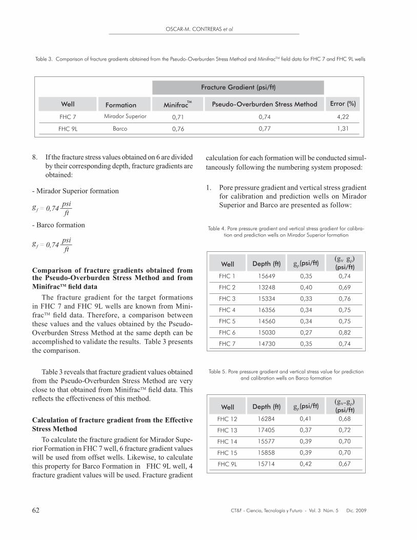
Comparison of fracture gradients obtained from the Pseudo-Overburden Stress Method and from MinifracTM
-fracthese values and the values obtained by the Pseudo-Overburden Stress Method at the same depth can be
the comparison.
from the Pseudo-Overburden Stress Method are very close to that obtained from Minifrac
Calculation of fracture gradient from the Effective Stress Method
-rior Formation in FHC 7 well, 6 fracture gradient values
fracture gradient values will be used. Fracture gradient
Table 3. Comparison of fracture gradients obtained from the Pseudo-Overburden Stress Method and MinifracTM field data for FHC 7 and FHC 9L wells
calculation for each formation will be conducted simul-taneously following the numbering system proposed:
1. Pore pressure gradient and vertical stress gradient for calibration and prediction wells on Mirador Superior and Barco are presented as follow:
Table 4. Pore pressure gradient and vertical stress gradient for calibra-tion and prediction wells on Mirador Superior formation
Well
Depth (ft)
FHC 1
FHC 2
FHC 3
FHC 4
FHC 5
FHC 6
FHC 7
15649
13248
15334
16356
14560
15030
14730
0,35
0,40
0,33
0,34
0,34
0,27
0,35
0,74
0,69
0,76
0,75
0,75
0,82
0,74
g
(psi/ft)
(psi/ft)
(g
�
g (
Table 5. Pore pressure gradient and vertical stress value for prediction and calibration wells on Barco formation
Well
Depth (ft)
FHC 12
FHC 13
FHC 14
FHC 15
FHC 9L
g
(psi/ft)
(psi/ft)
(g g (
16284
17405
15577
15858
15714
0,41
0,37
0,39
0,39
0,42
0,68
0,72
0,70
0,70
0,67
Mirador Superior
Barco
FHC 7
FHC 9L
Fracture Gradient (psi/ft)
Well
Formation Minifrac
TM
Pseudo-Overburden Stress Method
Error (%)
0,71
0,76
0,74
0,77
4,22
1,31
METHODOLOGY TO CALCULATE THE FRACTURE GRADIENT IN A TECTONICALLY ACTIVE ZONE
CT&F - Ciencia, Tecnología y Futuro - Vol. 3 Núm. 5 Dic. 2009 63
2. Minifrac
3.data for calibration wells are collected.
4. Effective fracture gradient values and effective vertical stress gradient values for each well are calculated.
5.value (Equation 6) for calibration wells in each formation is determined.
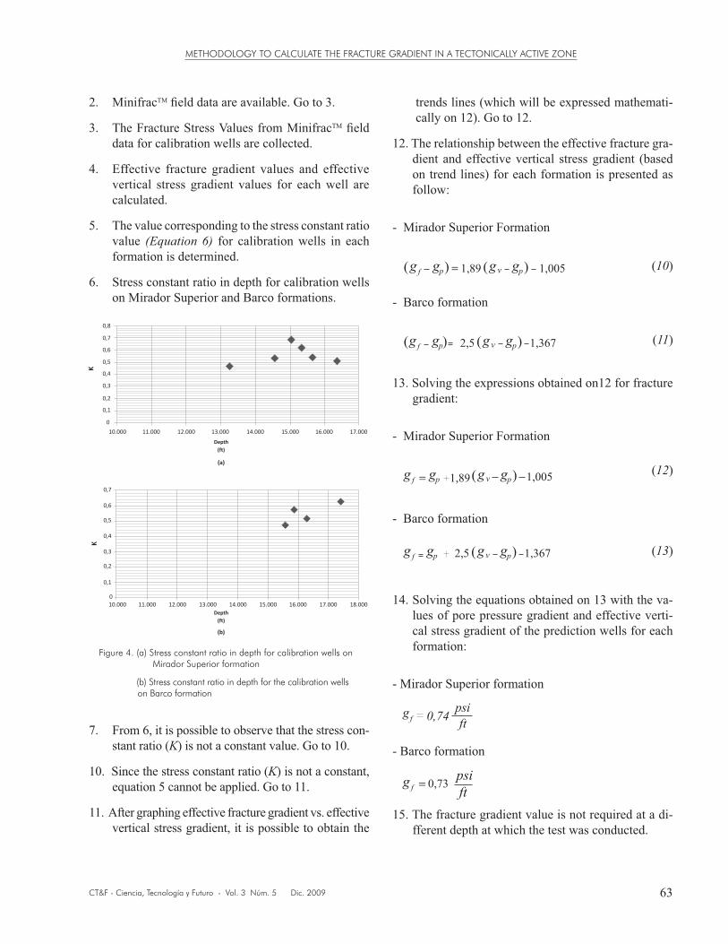
6. Stress constant ratio in depth for calibration wells on Mirador Superior and Barco formations.
Figure 4. (a) Stress constant ratio in depth for calibration wells on Mirador Superior formation
(b) Stress constant ratio in depth for the calibration wells on Barco formation
7. From 6, it is possible to observe that the stress con-stant ratio (K) is not a constant value. Go to 10.
10. Since the stress constant ratio (K) is not a constant, equation 5 cannot be applied. Go to 11.
11. After graphing effective fracture gradient vs. effective vertical stress gradient, it is possible to obtain the
trends lines (which will be expressed mathemati-cally on 12). Go to 12.
-dient and effective vertical stress gradient (based on trend lines) for each formation is presented as follow:
- Mirador Superior Formation
(
g g
p
) (
g
v
g
p
)
1,89 1,005
- Barco formation
g g
p
(
g
v
g
p
)
2,5 1,367
( )
13. Solving the expressions obtained on12 for fracture gradient:
- Mirador Superior Formation
g g
p
(
g
v
g
p
)
1,89
1,005
- Barco formation
g g
p
(
g
v
g
p
)
2,5 1,367
14. Solving the equations obtained on 13 with the va-lues of pore pressure gradient and effective verti-cal stress gradient of the prediction wells for each formation:
- Mirador Superior formation
- Barco formation
fferent depth at which the test was conducted.
(10)
(11)
(12)
(13)
CT&F - Ciencia, Tecnología y Futuro - Vol. 3 Núm. 5 Dic. 2009
OSCAR-M. CONTRERAS et al
64
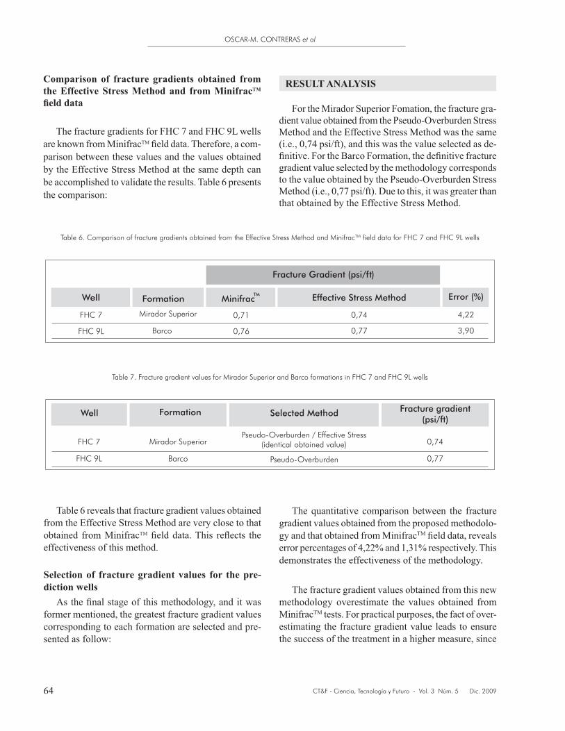
Comparison of fracture gradients obtained from the Effective Stress Method and from MinifracTM
are known from Minifrac -parison between these values and the values obtained by the Effective Stress Method at the same depth can
the comparison:
from the Effective Stress Method are very close to that obtained from Minifraceffectiveness of this method.
Selection of fracture gradient values for the pre-diction wells
former mentioned, the greatest fracture gradient values corresponding to each formation are selected and pre-sented as follow:
Table 6. Comparison of fracture gradients obtained from the Effective Stress Method and MinifracTM field data for FHC 7 and FHC 9L wells
Table 7. Fracture gradient values for Mirador Superior and Barco formations in FHC 7 and FHC 9L wells
RESULT ANALYSIS
For the Mirador Superior Fomation, the fracture gra-dient value obtained from the Pseudo-Overburden Stress Method and the Effective Stress Method was the same (i.e., 0,74 psi/ft), and this was the value selected as de-
gradient value selected by the methodology corresponds to the value obtained by the Pseudo-Overburden Stress Method (i.e., 0,77 psi/ft). Due to this, it was greater than that obtained by the Effective Stress Method.
gradient values obtained from the proposed methodolo-gy and that obtained from Minifrac
demonstrates the effectiveness of the methodology.
methodology overestimate the values obtained from Minifrac tests. For practical purposes, the fact of over-estimating the fracture gradient value leads to ensure the success of the treatment in a higher measure, since
METHODOLOGY TO CALCULATE THE FRACTURE GRADIENT IN A TECTONICALLY ACTIVE ZONE
CT&F - Ciencia, Tecnología y Futuro - Vol. 3 Núm. 5 Dic. 2009 65
this value conditions the operational design (hydraulic power requirements) to accomplish the treatment.
CONCLUSIONS
-late a fracture gradient value involving two new methods: Pseudo-Overburden Stress Method and Effective Stress Method. A reliable fracture gra-dient value with low associated uncertainty was obtained from this methodology.
Despite the different considerations which each method is based on, the fracture gradient values obtained from them for the Barco formation are considerably closed (i.e., 0,73 and 0,77 psi/ft) and for Mirador Superior formation are the same (i.e., 0,74 psi/ft).
applied in formations with different characteristics to that presented in this work, this due to the fact that two new methods that compose the methodo-logy are calibrated from real characteristics of the target formation, leading to predictions based on real formation conditions.
from this methodology are not very high at all despite the issue that Colombian Andean Foothills experiments strike-slip Faulting Regime is a sub-
some geomechanical studies in Colombian Fields (Mateus, Corzo, García & Marín, 2008) that even
-ture gradient values reach values up to 0,9 psi/ft.
Kø and øo values obtained from the Pseudo-Overburden Stress Method and the ratios between the vertical and horizontal stress gradients obtained from the Effective Stress Method for Mirador Su-perior and Barco formations can be extrapolated to the same formations through Colombian Andean Foothills, ensuring no important variations in the faulting regime.
ACKNOWLEDGMENTS
gratitude to Universidad Industrial de Santander (UIS),
(UIS – ICP Agreement) for their unconditional support during the development of this work.
REFERENCES
(1998). Comparison off leak-off test and extended leak-off test data for stress estimation. SPE/ISRM Eurock’ 98, Trondheim, Norway. SPE 47235.
Application of a new model to analyze leak-off test. 1999Annual Technical Conference and Exhibition, Houston. SPE 72061.
Anderson, R. A., Ingram, D.S. & Zanier, A. M. (1973). Deter-mining fracture pressure gradients from well logs. Journal of Petroleum Technology, 25, (11).
Brennan, R. M. & Annis, M. R. (1984). A new fracture gradi-ent prediction technique that shows good results in Gulf of Mexico abnormal pressure. 59th Annual Technical Confe-rence and Exhibition, Houston, Texas. SPE 13210.
Eaton, B. A. (1969). Fracture gradient prediction and its Journal of petroleum
technology, 21 (10).
Fjaer, E., Holt, R. M., Horsrud, P., Raaen, A. & Risnes, R. (1996). Petroleum related rock mechanics. Developments in petroleum science, 33, (1). 269-282.
-draulic fracturing. Petroleum Branch Fall Meeting, Los Angeles. AIME 210: 153-66.
Mateus, D., Corzo, R., García, R. & Marín, M. (2008). Estudio Geomecánico Prospecto Petrolea Sur. Informe Técnico, Ecopetrol S.A.- Instituto Colombiano del Petróleo (ICP).
CT&F - Ciencia, Tecnología y Futuro - Vol. 3 Núm. 5 Dic. 2009
OSCAR-M. CONTRERAS et al
66
presented at the 1994 SPE Intl. Petroleum Conference and Exhibition of Mexico, in Veracruz, Mexico. SPE 28710.
pressure and pore pressure. 52nd Annual Fall Technical Conference and Exhibition of the Society of Petroleum Engineers of AIME, Denver, Colorado. SPE 6870.
matic design and analysis of step-rate tests to determine formation parting pressure. 62nd Annual Technical Conference and Exhibition of the Society of Petroleum Engineers Dallas, TX, SPE 16798-MS.
Zoback, M. D. (2007). Reservoir geomechanics. (First edi-tion). Cambridge: Cambridge University Press.
Related Documents