Metacenter and ship stability Jacques M´ egel, Janis Kliava To cite this version: Jacques M´ egel, Janis Kliava. Metacenter and ship stability. American Journal of Physics, American Association of Physics Teachers, 2010, 78 (7), pp.738-747. . HAL Id: hal-00390980 https://hal.archives-ouvertes.fr/hal-00390980 Submitted on 4 Jun 2009 HAL is a multi-disciplinary open access archive for the deposit and dissemination of sci- entific research documents, whether they are pub- lished or not. The documents may come from teaching and research institutions in France or abroad, or from public or private research centers. L’archive ouverte pluridisciplinaire HAL, est destin´ ee au d´ epˆ ot et ` a la diffusion de documents scientifiques de niveau recherche, publi´ es ou non, ´ emanant des ´ etablissements d’enseignement et de recherche fran¸cais ou ´ etrangers, des laboratoires publics ou priv´ es.

Welcome message from author
This document is posted to help you gain knowledge. Please leave a comment to let me know what you think about it! Share it to your friends and learn new things together.
Transcript

Metacenter and ship stability
Jacques Megel, Janis Kliava
To cite this version:
Jacques Megel, Janis Kliava. Metacenter and ship stability. American Journal of Physics,American Association of Physics Teachers, 2010, 78 (7), pp.738-747. .
HAL Id: hal-00390980
https://hal.archives-ouvertes.fr/hal-00390980
Submitted on 4 Jun 2009
HAL is a multi-disciplinary open accessarchive for the deposit and dissemination of sci-entific research documents, whether they are pub-lished or not. The documents may come fromteaching and research institutions in France orabroad, or from public or private research centers.
L’archive ouverte pluridisciplinaire HAL, estdestinee au depot et a la diffusion de documentsscientifiques de niveau recherche, publies ou non,emanant des etablissements d’enseignement et derecherche francais ou etrangers, des laboratoirespublics ou prives.
1
On the buoyancy force and the metacentreOn the buoyancy force and the metacentreOn the buoyancy force and the metacentreOn the buoyancy force and the metacentre Jacques Mégel and Janis Kliava
UFR de Physique, Université de Bordeaux 1
351 cours de la Libération,
33405 Talence cedex, France
AbstractAbstractAbstractAbstract
We address the point of application A of the buoyancy force (also known as the Archimedes force) by using two
different definitions of the point of application of a force, derived one from the work-energy relation and another one from
the equation of motion. We present a quantitative approach to this issue based on the concept of the hydrostatic energy,
considered for a general shape of the immersed cross-section of the floating body. We show that the location of A depends
on the type of motion experienced by the body. In particular, in vertical translation, from the work-energy viewpoint, this
point is fixed with respect to the centre of gravity G of the body. In contrast, in rolling/pitching motion there is duality in
the location of A ; indeed, the work-energy relation implies A to be fixed with respect to the centre of buoyancy C, while
from considerations involving the rotational moment it follows that A is located at the metacentre M. We obtain analytical
expressions of the location of M for a general shape of the immersed cross-section of the floating body and for an arbitrary
angle of heel. We show that three different definitions of M viz., the “geometrical” one, as the centre of curvature of the
buoyancy curve, the Bouguer’s one, involving the moment of inertia of the plane of flotation, and the “dynamical” one,
involving the second derivative of the hydrostatic energy, refer to one and the same special point, and we demonstrate a
close relation between the height of M above the line of flotation and the stability of the floating body. Finally, we provide
analytical expressions and graphs of the buoyancy, flotation and metacentric curves as functions of the angle of heel, for
some particular shapes of the floating bodies, viz., a circular cylinder, a rectangular box, a parabolic and an elliptic cylinder.
I. IntroductionI. IntroductionI. IntroductionI. Introduction
“If a solid lighter than a fluid be forcibly immersed in it, the solid will be driven upwards by a force equal to the “If a solid lighter than a fluid be forcibly immersed in it, the solid will be driven upwards by a force equal to the “If a solid lighter than a fluid be forcibly immersed in it, the solid will be driven upwards by a force equal to the “If a solid lighter than a fluid be forcibly immersed in it, the solid will be driven upwards by a force equal to the
difference bedifference bedifference bedifference between its weight and the weight of the fluid displacedtween its weight and the weight of the fluid displacedtween its weight and the weight of the fluid displacedtween its weight and the weight of the fluid displaced.”.”.”.” 1, p. 257
One of the most long-standing – for 22 centuries – and, perhaps, one of the best-known laws
of physics is the Archimedes’ Law stating that a body immersed in a fluid is subjected to a force equal
to the weight of the displaced fluid and acting in opposite direction to the force of gravity. This force is
called “buoyancy force” or “Archimedes’ force”; we denote it by hF , the subscript “h” standing for
“hydrostatic”, and its point of application will be referred to as A.
2
Clearly, hF is a resultant of all elementary hydrostatic forces applied to the surface of the
immersed body. A force is fully described by (i) its norm, (ii) its direction and (iii) its point of
application. Note that the point (iii) is not included in the above definition of the Archimedes' Law. On
the other hand, it would be surprising if such a fundamental epistemological question as that of the
point of application of the buoyancy force were not at all discussed in the literature.
By definition of the resultant force, the point of application of hF should be defined by
requiring that if we apply such a force, the (macroscopic) behaviour of the body will be the same as that
caused by the ensemble of elementary hydrostatic forces. Note, however, that this definition does not
guarantee the uniqueness of this point; indeed, one may quite well conceive it to be different in
different physical situations.
An analysis of the abundant bibliography concerned with the stability of immersed bodies
shows that many authors prefer to elude the question of the exact location of the point of application
of the Archimedes’ force, e.g., speaking of “the line of action” of this force. 2, p. 73 What is really shown is
only that the line of application of the Archimedes’ force passes through the centre of buoyancy, so that
one may guess that A can be located anywhere on this line. If this statement is sufficient in statics, it is
certainly not sufficient in dynamics. Indeed, one might argue that a force applied to a rigid body, as a
sliding vector, obeys to the principle of transmissibility stating that “the condition of motion of a rigid body
remains unchanged if a force F of a given magnitude, direction and sense acts anywhere along the same line of action…”.3
However, in this relation, an important amendment had been made already more than a century ago,
namely, that “we may imagine a force to be applied at any point in the line of its direction, provided this point be rigidly
connected with the first point of application”. 4 Below, we will show that, while a floating body can be
considered as rigid, the point of application of hF is not necessarily rigidly connected with it because
the displaced fluid is evidently not rigid. Therefore the question of the point of application of this force
is quite legitimate and meaningful.
In a quite natural way one is tempted to relate the point of application of hF to one of the three
following remarkable points of a floating body.
(i) The centre of gravity of the body, denoted by G (the distinction between the centre of gravity and
that of mass/inertia is of no relevance for the present analysis). To our knowledge, such assignment has
never been suggested before.
(ii) The centre of buoyancy (centre of gravity of the displaced fluid) denoted by C (from careen) or
by B (from buoyancy); we prefer using the former notation. Note that C sometimes is defined as the
geometrical centre of the displaced fluid; meanwhile, for a homogeneous fluid (the case considered
below) both definitions coincide. Most frequently, the point of application of hF is assigned to the
centre of buoyancy, e.g., see Refs. [5 (p. 58), 6, 7].

3
(iii) The metacentre denoted by M. This point is of a special interest, since, in order to assert the
stability of the body against overturn, M, defined in the vicinity of equilibrium, should be located above
G. We have found only one textbook suggesting, without demonstration, M as a candidate for the
point of application of hF , see Ref. [8, footnote p. 26]. On the other hand, in a very interesting while,
unfortunately, not easily accessible paper, Herder and Schwab 9 suggest a distinction between “statically
equivalent” and “dynamically equivalent” resultant forces. The former are defined for a fixed position
of the body (statics) in which case only a line and not a point of application of the resultant can be
defined. The latter are related to the stability of a nominal state with respect to small variations about
this state. In this case the point of application of the resultant force is essential, and these authors
define it as the “dynamically equivalent” point of application. For the particular case of floating
parallepiped (“shoe-box”) Herder and Schwab deduce from considerations based on the hydrostatic
energy that the “dynamically equivalent” point of application of the buoyancy force is the metacentre.
It has seemed quite tempting to generalize this approach to the general case of the floating body of
arbitrary shape, inclined through an arbitrary angle.
The concept of metacentre dates back to Bouguer’s Traité du Navire, de sa construction et de ses
mouvemens (1746) 10. Using the prefix µετά = “beyond”, he had designated a specific point M of a
floating body, defined as the intersection of two vertical axes passing through the centre of buoyancy C
(the centre of gravity of the displaced fluid) at two slightly different angles of heel. Besides, Bouguer
formulated the well-known theorem relating the distance between C and M to the ratio of the moment
of inertia of the plane of flotation and the volume of the displaced fluid.
Three years later, Euler in Scientia navalis (1749) gave a general criterion of the ship stability,
based on the restoring moment: 11 the ship remains stable as far as the couple weight (applied at G) and
the buoyancy force (whose line of application passes through C) creates a restoring moment. A change
of sign of the latter results in capsizing, and its vanishing in inclined position (at equilibrium it vanishes
by definition) corresponds to the overturn angle.
The problem of stability of the floating bodies, which can be traced back to Archimedes
himself, see [1, On floating bodies, Book I, pp. 253-262; Book II, pp. 263-300], has never ceased to interest
scientists and engineers 12-16, in particular, in the relation to the metacentre, e.g., see 7, 17-20 and has
become an important part of academic studies 2, 5, 6, 8, 21. Meanwhile, there has been no significant
progress in this field since the original Bouguer’s Treatise 10 and its reformulation in terms of a “novel
geometry” in the Dupin’s textbook 17 , relating the metacentric curve, i.e., the loci of M, with the buoyancy
curve formed by the loci of C, the former being the evolute of the latter.
The aim of the present work is to elucidate the question of the point of application of the
buoyancy force in relation with that of ship stability. We consider two different approaches to the
definition of the point of application of a resultant force based, first, on the work-energy relation and,
4
second, on the equation of motion. We obtain appropriate expressions of the hydrostatic energy and
the location of the characteristic points for a floating body of rather general shape. On this basis we
show that the location of the point of application of the buoyancy force depends on the type of motion
experienced by the body. In particular, in pure translation this point is fixed with respect to the centre
of gravity G while in rolling or pitching motion it is fixed with respect to the centre of buoyancy C
(from the viewpoint of the work-energy relation) or located at the metacentre M (from the viewpoint of
the rotational moment).
In the framework of the formalism developed in this work, we present a quantitative analysis of
the concept of the metacentre. We calculate the location of the “geometrical”, Bouguer’s and
“dynamical” metacentres for an arbitrary angle of heel and show that all three definitions, in fact, result
in one and the same metacentric curve. Finally, in the Appendix we apply the general relationships to
determine the location of C and M for several particularly simple shapes of the floating body.
II. Buoyancy force and hydrostatic energyII. Buoyancy force and hydrostatic energyII. Buoyancy force and hydrostatic energyII. Buoyancy force and hydrostatic energy
Consider a floating, i.e., partially immersed in a fluid, rigid body, e.g., a vessel. In such situation,
strictly speaking, one should also take into account the atmospheric pressure experienced by the part of
the body situated above the waterline. However, as far as the specific density of the air remains much
lower than that of the fluid, as we have assumed in the analysis given below, the atmospheric pressure
can be neglected. In the formulae given below the surface S and the volume V concern only the
submerged part of the body, V being equal to the volume of the displaced fluid.
The hydrostatic force exerted on an element dS of the immersed surface of the body is
hd dp=−F S where p is the hydrostatic pressure. The minus sign in this expression is due to the fact
that, by convention, dS is directed outwards a closed surface while the hydrostatic force is directed
inwards the body. Integrating hdF over the immersed surface and applying the gradient theorem to
pass from a surface integral to an integral over the immersed volume V yields the buoyancy force as:
h d dS V
p p V=− =− ∇∫∫ ∫∫∫F S� . (II.1)
Eq. (II.1) shows that hF can also be considered as a resultant of fictitious volume forces of
density per unit volume of the fluid hd dV p=−∇F , deriving from a potential energy (hydrostatic
energy) of density p. The total hydrostatic energy is calculated as
h dV
E p V= ∫∫∫ . (II.2)
5
From the general relation between a force and the corresponding potential energy it follows
that h hE=−∇F .
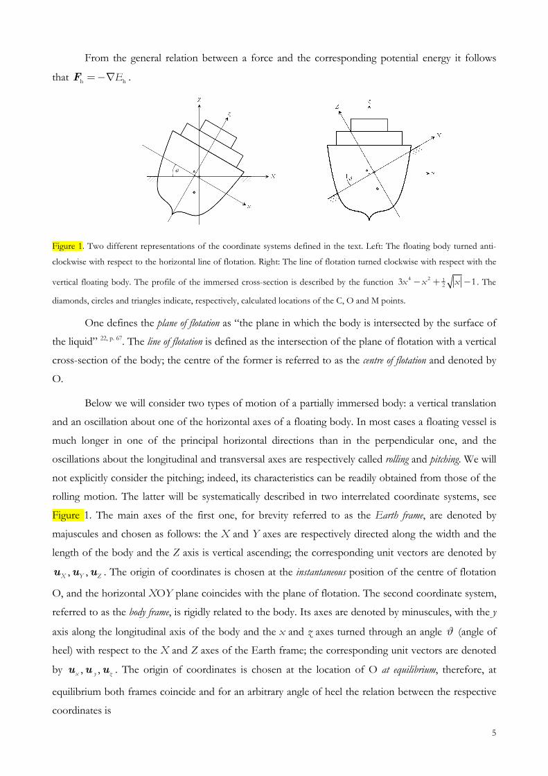
Figure 1. Two different representations of the coordinate systems defined in the text. Left: The floating body turned anti-
clockwise with respect to the horizontal line of flotation. Right: The line of flotation turned clockwise with respect with the
vertical floating body. The profile of the immersed cross-section is described by the function 4 2 1
23 1x x x− + − . The
diamonds, circles and triangles indicate, respectively, calculated locations of the C, O and M points.
One defines the plane of flotation as “the plane in which the body is intersected by the surface of
the liquid” 22, p. 67. The line of flotation is defined as the intersection of the plane of flotation with a vertical
cross-section of the body; the centre of the former is referred to as the centre of flotation and denoted by
O.
Below we will consider two types of motion of a partially immersed body: a vertical translation
and an oscillation about one of the horizontal axes of a floating body. In most cases a floating vessel is
much longer in one of the principal horizontal directions than in the perpendicular one, and the
oscillations about the longitudinal and transversal axes are respectively called rolling and pitching. We will
not explicitly consider the pitching; indeed, its characteristics can be readily obtained from those of the
rolling motion. The latter will be systematically described in two interrelated coordinate systems, see
Figure 1. The main axes of the first one, for brevity referred to as the Earth frame, are denoted by
majuscules and chosen as follows: the X and Y axes are respectively directed along the width and the
length of the body and the Z axis is vertical ascending; the corresponding unit vectors are denoted by
, ,X Y Zu u u . The origin of coordinates is chosen at the instantaneous position of the centre of flotation
O, and the horizontal XOY plane coincides with the plane of flotation. The second coordinate system,
referred to as the body frame, is rigidly related to the body. Its axes are denoted by minuscules, with the y
axis along the longitudinal axis of the body and the x and z axes turned through an angle ϑ (angle of
heel) with respect to the X and Z axes of the Earth frame; the corresponding unit vectors are denoted
by , ,x y zu u u . The origin of coordinates is chosen at the location of O at equilibrium, therefore, at
equilibrium both frames coincide and for an arbitrary angle of heel the relation between the respective
coordinates is
6
( ) ( )( ) ( )
O O
O O
cos sin
sin cos
X x x z z
Z x x z z
ϑ ϑ
ϑ ϑ
= − + −
=− − + −. (II.3)
We suppose that, as is most often the case, the fluid can be considered as incompressible and
homogeneous, so that the hydrostatic pressure depends only on the immersion depth:
fp gZµ=− where fµ is the specific density of the fluid and g is the acceleration of gravity. Then eqs.
(II.1), (II.2) become:
fh f d Z Z
V
g V gVµ µ= =∫∫∫F u u (II.4)
and
fh dV
E g Z Vµ=− ∫∫∫ . (II.5)
III. III. III. III. Two definitions of the point of application of a forceTwo definitions of the point of application of a forceTwo definitions of the point of application of a forceTwo definitions of the point of application of a force
By definition of the centre of buoyancy, its coordinates are
C C C
1 1 1d ; d ; d
V V V
X X V Y Y V Z Z VV V V
= = =∫∫∫ ∫∫∫ ∫∫∫ , (III.1)
therefore, from eqs. (II.5) and (III.1),
h f ChCE gVZ F Zµ=− =− . (III.2)
The concept of the hydrostatic energy allows defining the point of application of the buoyancy
force from the usual work-energy relation, e.g., see ref. [22]. The elementary work is defined as the
scalar product of a force with an elementary displacement of its point of application; on the other hand,
for a force deriving from a potential energy it equals the diminution of this energy. In the present case,
h h hA A hd d dW F Z Eδ = ⋅ = =−rF . (III.3)
If the displacement of the point A matches that of a definite point of the body, the latter point can be
identified as the point of application of hF . As far as the above identification is based on the work-
energy relation, the corresponding point will be referred to as the “energetical” point of application of
the buoyancy force. This definition applies for any type of motion.
Another possibility of defining the point of application of hF is based on the principle that the
rotational moment of a force vanishes in its point of application. This definition is applicable to types
of motion where a rotational component is present, in particular, to rolling/pitching. A floating body

7
experiences both the buoyancy force hF and the force of gravity gF , and its total potential energy is
the sum of the hydrostatic and gravitational energies, total h gE E E= + . The couple h g+F F produces a
rotational moment (torque) total h G gA= ∧ + ∧M r F r F where rrrrA and rrrrG are position vectors of A and G
with respect to an arbitrary coordinate system; obviously, totalM does not depend on the choice of the
origin of coordinates.
The strategy usually adopted in mechanics is to separate a general motion of the body into
translation of an arbitrary point, chosen inside or outside the body, and rotation about this point. Most
often the centre of rotation is chosen at G, in which case G 0=r , but this choice is not compulsory.
For a floating body the location of G depends not only of its shape but also of the distribution of
weights inside the hull, which changes with the ship loading. Therefore, we have chosen to focus on the
buoyancy force and the related hydrostatic energy without systematically calling to mind the force of
gravity and its potential energy.
However, the rotational moment of the single force hF does depend on the origin of rrrrA,
therefore, in considering only the buoyancy force and the hydrostatic energy, the choice of the origin of
coordinates is physically meaningful. The famous Euler’s theorem 11 states the following.
“TTTThe oscillatory movement of a floating body (rollhe oscillatory movement of a floating body (rollhe oscillatory movement of a floating body (rollhe oscillatory movement of a floating body (rollinginginging or pitchor pitchor pitchor pitchinginginging) can be described as a rotation about ) can be described as a rotation about ) can be described as a rotation about ) can be described as a rotation about the cethe cethe cethe centre ntre ntre ntre
of flotation of flotation of flotation of flotation OOOO....””””
Choosing O as the origin of Ar , the rotational moment of the buoyancy force, hM is
calculated from a variation of Eh:
( ) ( )h A h A h A h hd d d d dE =− ⋅ =− ∧ ⋅ =− ⋅ ∧ =− ⋅r F r F r F MΘ Θ Θ (III.4)
where the elements of the angle vector ( ), , 0ϕ ϑΘ= are angles of rotation about the X and Y
axes. In deriving eq. (III.4) we have used the expression of variation of a position vector rrrr in an
infinitesimal rotation, d d= ∧r rΘ . From the latter equation one gets h hEΘ=−∇M where elements
of the gradient Θ∇ are derivatives with respect to the angles of rotation. In the particular case of
rolling, the only non-vanishing element of hM is
hh Y
E
ϑ
∂=−
∂M u . (III.5)
On the other hand, hM is the sum of moments of the elementary hydrostatic forces, so, for a
homogeneous fluid it can be calculated as
h h fd dS S
g Zµ= ∧ = ∧∫∫ ∫∫M r F r S� � . (III.6)
8
Applying the curl theorem and taking into account that the curl of the radius vector is identically null,
0000∇∧ ≡r , we get
( ) ( )fh fd dV
Y X
V
g Z XV g Y Vµ µ=− ∇∧ = − +∫∫ ∫∫ ∫∫ u uM r . (III.7)
By definition of the moment of the buoyancy force,
( )h A h A Afh A Z Y XgVF X Yµ= ∧ = − +∧ =M r r uu uF . (III.8)
From eqs. (III.7) and (III.8) we obtain the coordinates of A in the horizontal plane as the first
moments of the immersed volume about the X and Y axes. These coordinates coincide with the
corresponding coordinates of C, cf. eqs. (III.1):
A A
1 1d ; d
V V
X X V Y Y VV V
= =∫∫∫ ∫∫∫ . (III.9)
XA and YA give the lengths of the lever arms of hF for rolling and pitching, respectively. Therefore, hF
is applied along the vertical line passing through C. Meanwhile, as one might expect, the vertical coordinate
ZA of the point of application of hF remains undefined.
Interestingly, if we attempt to determine the centre of gravity of a body from vanishing of the
corresponding rotational moment in a given position, its vertical coordinate ZG will also remain undefined.
Meanwhile, this difficulty is readily overcome by rotating the body through an arbitrary angle about any
non-vertical axis. From the viewpoint of such experience, the point of application of the weight can be
defined as the “intersection of all vertical lines passing through the centre of gravity for different
angular positions of the body”. The same procedure can be used to specify ZA, and as will be discussed
later, the “intersection of all vertical lines passing through the centre of gravity of the displaced fluid (i.e.
the centre of buoyancy) for different angular positions of the body”, by definition, indicates the
metacentre.
Therefore, we need an equation of motion involving hM and containing ZA. In eq. (III.8) ZA is
eliminated because of the properties of the vector product A h∧r F , so, in a somewhat intuitive way,
one may suggest an equation satisfied by the corresponding scalar product A h⋅r F . It can be obtained
considering the equation of rotation of a solid: h=M��ΘI where I is the tensor of inertia about O and
the elements of the angle vector ��Θ , the second derivative of Θ , are angular accelerations around the X
and Y axes. In order to account for a small rotation about the state of the body described by this
equation, we take the differentials of its both sides:
( ) ( )h A h h Ad d d dΘ= = ∧ ∧ = ∧ ∧�� M r F F rI Θ Θ . (III.10)
9
Developing the double vector product and making use of the fact that hF is vertical while dΘ
is horizontal, yields
( ) ( ) ( )h A h A h A hd d d d= ⋅ − ⋅ =− ⋅M r F r F r FΘ Θ Θ . (III.11)
In the case of the rolling motion, from eqs. (III.5) and (III.11) we get for the sought-after scalar
product:
hhA h A h
d²
² dY
MEZ F
ϑ ϑ
∂=− = ⋅ =
∂r F . (III.12)
Thus, defining the vertical coordinate of the point of application of hF , we are led to the
following theorem:
ThThThThe scalar product of the buoyancy force and the position vector of its point of application from the origin at the e scalar product of the buoyancy force and the position vector of its point of application from the origin at the e scalar product of the buoyancy force and the position vector of its point of application from the origin at the e scalar product of the buoyancy force and the position vector of its point of application from the origin at the
centre of flotation is given by minus the derivative of the rotational moment with respect to the centre of flotation is given by minus the derivative of the rotational moment with respect to the centre of flotation is given by minus the derivative of the rotational moment with respect to the centre of flotation is given by minus the derivative of the rotational moment with respect to the angle of angle of angle of angle of roll or pitch or by roll or pitch or by roll or pitch or by roll or pitch or by
the second derithe second derithe second derithe second derivative of the hydrostatic energy with respect to this anglevative of the hydrostatic energy with respect to this anglevative of the hydrostatic energy with respect to this anglevative of the hydrostatic energy with respect to this angle.
This result can be considered as a particular case of the general analysis of the “dynamically
equivalent” point of application given by Herder and Schwab 9.
Eqs. (III.9) and (III.12) are necessary and sufficient to determine all the three coordinates of the
point of application of hF . As this determination is based on dynamical equations involving the
rotational moment, this point will be referred to as the “dynamical” point of application of the
buoyancy force.
It is easy to show that the second derivative of the total potential energy can be expressed as
( ) ( )totaltotalA G h A G h
d²
² dY
MEZ Z F
ϑ ϑ
∂=− = − ⋅ = −
∂r r F , (III.13)
directly yielding the vertical distance between G and A.
In what follows we present a model calculation of the location of the different points of
application of the buoyancy force. The calculations refer to the immersed part of the transversal cross-
section of the floating body for brevity denoted by “immersed cross-section”, so, the results given
below refer to a portion of the body of unit length along its longitudinal axis. The characteristics of the
whole body can be readily obtained by weighted integration along the y/Y axis.
10
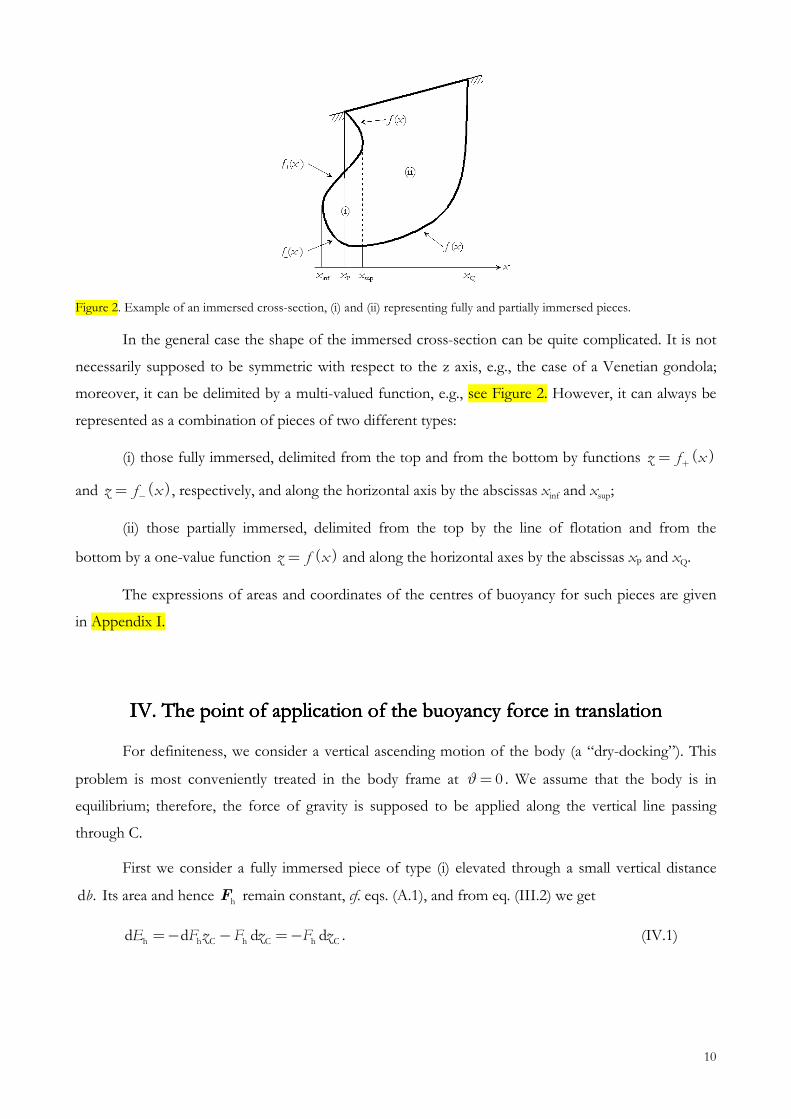
Figure 2. Example of an immersed cross-section, (i) and (ii) representing fully and partially immersed pieces.
In the general case the shape of the immersed cross-section can be quite complicated. It is not
necessarily supposed to be symmetric with respect to the z axis, e.g., the case of a Venetian gondola;
moreover, it can be delimited by a multi-valued function, e.g., see Figure 2. However, it can always be
represented as a combination of pieces of two different types:
(i) those fully immersed, delimited from the top and from the bottom by functions ( )z f x+=
and ( )z f x−= , respectively, and along the horizontal axis by the abscissas xinf and xsup;
(ii) those partially immersed, delimited from the top by the line of flotation and from the
bottom by a one-value function ( )z f x= and along the horizontal axes by the abscissas xP and xQ.
The expressions of areas and coordinates of the centres of buoyancy for such pieces are given
in Appendix I.
IVIVIVIV. The point of application of the buoyancy force in translation. The point of application of the buoyancy force in translation. The point of application of the buoyancy force in translation. The point of application of the buoyancy force in translation
For definiteness, we consider a vertical ascending motion of the body (a “dry-docking”). This
problem is most conveniently treated in the body frame at 0ϑ= . We assume that the body is in
equilibrium; therefore, the force of gravity is supposed to be applied along the vertical line passing
through C.
First we consider a fully immersed piece of type (i) elevated through a small vertical distance
d .b Its area and hence hF remain constant, cf. eqs. (A.1), and from eq. (III.2) we get
hh C C Ch hd dd dE F z F z F z=− − =− . (IV.1)
11
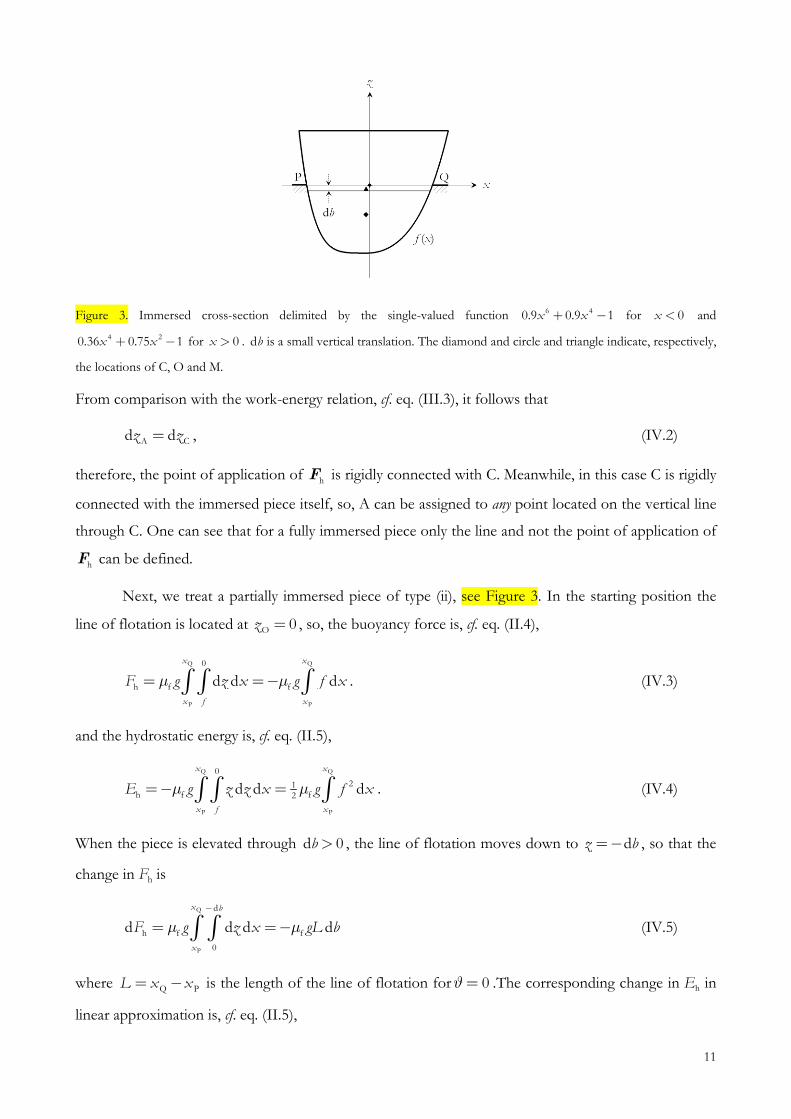
Figure 3. Immersed cross-section delimited by the single-valued function 6 40.9 0.9 1x x+ − for 0x < and
4 20.36 0.75 1x x+ − for 0x > . db is a small vertical translation. The diamond and circle and triangle indicate, respectively,
the locations of C, O and M.
From comparison with the work-energy relation, cf. eq. (III.3), it follows that
A Cd dz z= , (IV.2)
therefore, the point of application of hF is rigidly connected with C. Meanwhile, in this case C is rigidly
connected with the immersed piece itself, so, A can be assigned to any point located on the vertical line
through C. One can see that for a fully immersed piece only the line and not the point of application of
hF can be defined.
Next, we treat a partially immersed piece of type (ii), see Figure 3. In the starting position the
line of flotation is located at O 0z = , so, the buoyancy force is, cf. eq. (II.4),
Q Q
P P
0
h f fd d d
x x
x f x
F z x f xg gµ µ= =−∫ ∫ ∫ . (IV.3)
and the hydrostatic energy is, cf. eq. (II.5),
Q Q
P P
0
21h f f2
d d d
x x
x f x
gE z z x fg xµ µ=− =∫ ∫ ∫ . (IV.4)
When the piece is elevated through d 0b > , the line of flotation moves down to dz b=− , so that the
change in Fh is
Q
P
d
h f f
0
d d d d
x b
x
F z Lg bgxµ µ
−
== −∫ ∫ (IV.5)
where Q PL x x= − is the length of the line of flotation for 0ϑ= .The corresponding change in Eh in
linear approximation is, cf. eq. (II.5),

12
( )Q Q
P P
d 0
h f fd d d d d d
x xb
x f f x
E z b z zg x x bg fµ µ
− =− + − ≈ ∫ ∫ ∫ ∫ . (IV.6)
From eqs. (IV.3) and (IV.6) one gets:
h hd dE F b=− , (IV.7)
so, a comparison with eq. (III.3) shows that
Ad dz b= . (IV.8)
As in the case of a fully immersed piece, A is rigidly connected with the partially immersed piece in
translational motion.
For an immersed cross-section of a general shape the coordinates of A are weighted sums of
the corresponding coordinates of separate pieces, therefore A remains rigidly connected with such a
piece. As G is rigidly connected with the immersed body and, in translation, G is located on the axis of
application of hF , one can consider that hF is applied at G. This assignment being based on the work-
energy relation, the corresponding point of application of hF will be referred to as an “energetical”
one.
On the other hand, C is not rigidly connected with a partially immersed piece; therefore, in this
case it would be an error to consider that hF is applied at C. Indeed, from eqs. (III.2) and (IV.7),
hh C Ch hd d d dE F z F z F b=− − =− , (IV.9)
and substituting Fh, Eh, dFh and dEh from the respective expressions, one gets
Q Q
P P
21C 2
2
d d1 d d
x x
x x
z f x f x bL
−
= ∫ ∫ . (IV.10)
Obviously, only for a fully immersed body, when 0L = , one gets Cd dz b= . In other cases the
relation between the displacements of the body and of its centre of buoyancy can be very different.
The difference between Adz and Cdz is particularly obvious for a partially immersed
parallelepiped, ( )z f x const b= = =− for P Q,x x x ∈ , see Figure 4. In this case Q
P
dx
xf x bL=−∫
and Q
P
2 2dx
xf x b L=∫ , so that for a finite displacement b∆ eq. (IV.10) yields
12Cz b∆ ∆= . (IV.11)
13
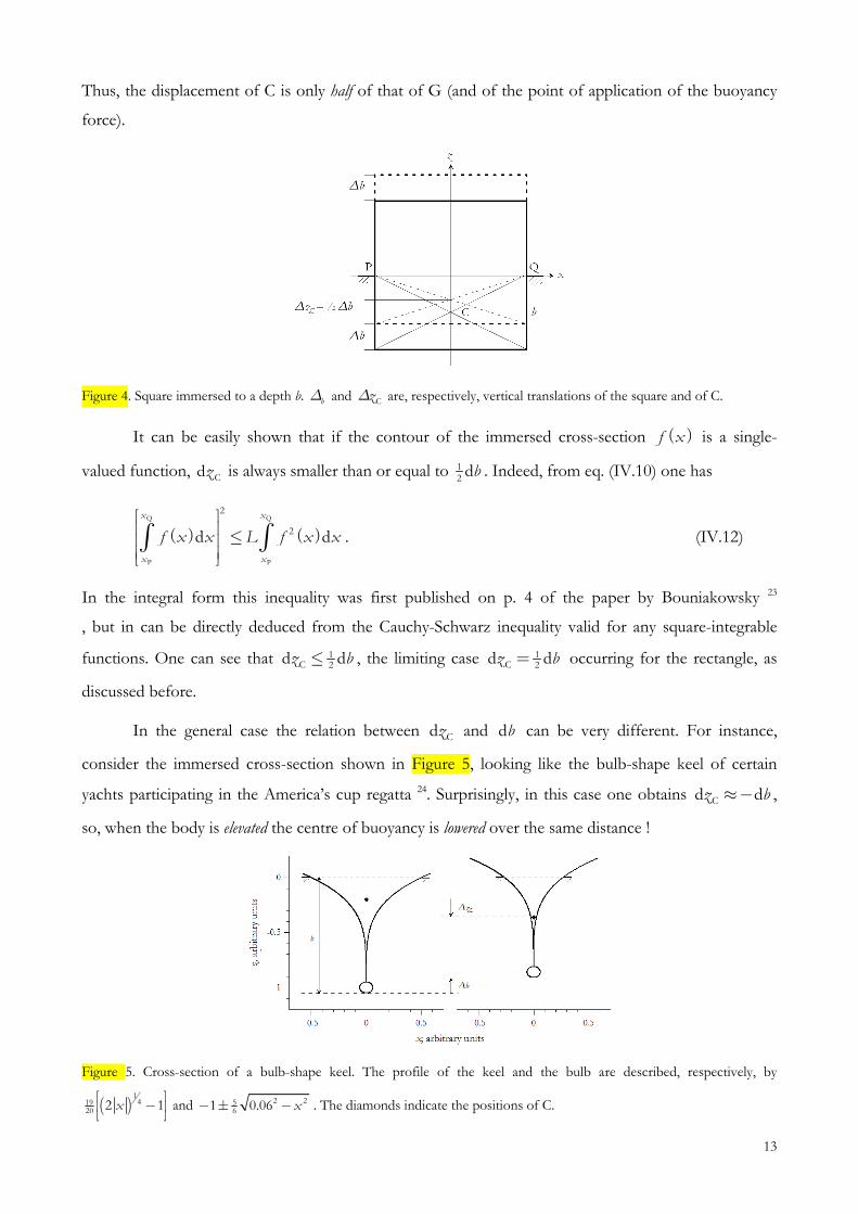
Thus, the displacement of C is only half of that of G (and of the point of application of the buoyancy
force).
Figure 4. Square immersed to a depth b. b∆ and Cz∆ are, respectively, vertical translations of the square and of C.
It can be easily shown that if the contour of the immersed cross-section ( )f x is a single-
valued function, Cdz is always smaller than or equal to 12
db . Indeed, from eq. (IV.10) one has
( ) ( )Q Q
P P
2
2d d
x x
x x
f x x L f x x ≤ ∫ ∫ . (IV.12)
In the integral form this inequality was first published on p. 4 of the paper by Bouniakowsky 23
, but in can be directly deduced from the Cauchy-Schwarz inequality valid for any square-integrable
functions. One can see that 12Cd dz b≤ , the limiting case 1
2Cd dz b= occurring for the rectangle, as
discussed before.
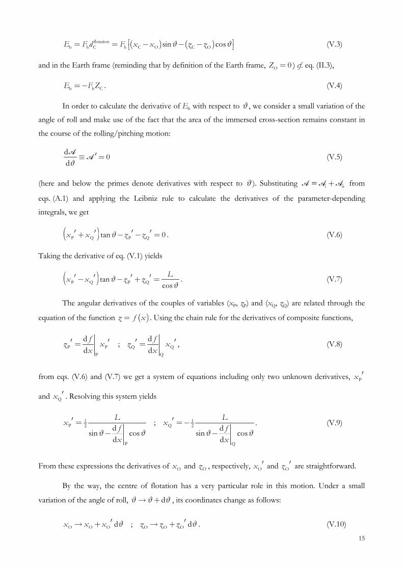
In the general case the relation between Cdz and db can be very different. For instance,
consider the immersed cross-section shown in Figure 5, looking like the bulb-shape keel of certain
yachts participating in the America’s cup regatta 24. Surprisingly, in this case one obtains Cd dz b≈− ,
so, when the body is elevated the centre of buoyancy is lowered over the same distance !
Figure 5. Cross-section of a bulb-shape keel. The profile of the keel and the bulb are described, respectively, by
( )1
41920 2 1x −
and 2 2561 0.06 x− ± − . The diamonds indicate the positions of C.

14
V. Duality of the poiV. Duality of the poiV. Duality of the poiV. Duality of the point of application of the buoyancy force in nt of application of the buoyancy force in nt of application of the buoyancy force in nt of application of the buoyancy force in
rolling/pitching motionrolling/pitching motionrolling/pitching motionrolling/pitching motion
Now we examine the location of the point of application in rolling/pitching. In the general
case, in this type of motion a rotation through an angle ϑ is combined with a vertical translation of the
centre of buoyancy, see Figure 6.
Figure 6. Two immersed cross-sections turned through an angle ϑ . Left: that of Figure 3; right: the one delimited by the
functions ( ) 23 34 2f x x+ = − (upper branch) and ( ) 21
2 1f x x− = − for 0x < and ( ) 612 1f x x− = − for 0x > (lower
branch). The full and empty diamonds, circles and triangles indicate, respectively, the locations of C, O and M before and
after the rotation.
At an arbitrary angle of heel the line of flotation is described by the equations
Q PO
O Q P
tanz zz z
x x x xϑ
−−= =
− − (V.1)
where the coordinates of O are
( )( )
1O P Q2
1O P Q2
x x x
z z z
= +
= +. (V.2)
The curve described by O in the course of the rolling/pitching motion is called flotation curve.
The area of the immersed cross-section and the coordinates of the centre of buoyancy are given
by eqs. (A.1), (A.3) and (A.4).
V. 1. Energetical considerationsV. 1. Energetical considerationsV. 1. Energetical considerationsV. 1. Energetical considerations
Denoting by flotation
Cd the depth of C below the line of flotation, Eh in the body frame is
expressed as
15
( ) ( )flotationh h C h C O C Osin cosE F d F x x z zϑ ϑ = = − − − (V.3)
and in the Earth frame (reminding that by definition of the Earth frame, O 0Z = ) cf. eq. (II.3),
h h CE F Z=− . (V.4)
In order to calculate the derivative of Eh with respect to ϑ , we consider a small variation of the
angle of roll and make use of the fact that the area of the immersed cross-section remains constant in
the course of the rolling/pitching motion:
d0
dϑ′≡ =
AA (V.5)
(here and below the primes denote derivatives with respect to ϑ ). Substituting i ii+A =A A from
eqs. (A.1) and applying the Leibniz rule to calculate the derivatives of the parameter-depending
integrals, we get
( )P Q P Qtan 0x x z zϑ′ ′ ′ ′+ − − = . (V.6)
Taking the derivative of eq. (V.1) yields
( )P Q P Qtancos
Lx x z zϑ
ϑ′ ′ ′ ′− − + = . (V.7)
The angular derivatives of the couples of variables (xP, zP) and (xQ, zQ) are related through the
equation of the function ( )z f x= . Using the chain rule for the derivatives of composite functions,
P P Q Q
P Q
d d;
d d
f fz x z x
x x′ ′ ′ ′= = , (V.8)
from eqs. (V.6) and (V.7) we get a system of equations including only two unknown derivatives, Px ′
and Qx ′ . Resolving this system yields
1 1P Q2 2
P Q
;d d
sin cos sin cosd d
L Lx x
f f
x xϑ ϑ ϑ ϑ
′ ′ ==−
−−
. (V.9)
From these expressions the derivatives of Ox and Oz , respectively, Ox ′ and Oz ′ are straightforward.
By the way, the centre of flotation has a very particular role in this motion. Under a small
variation of the angle of roll, dϑ ϑ ϑ→ + , its coordinates change as follows:
O O O O O Od ; dx x x z z zϑ ϑ′ ′→ + → + . (V.10)
16
The initial and the new lines of flotation are described by, cf. eq. (V.1),
( ) ( )
( ) ( ) ( )
( )
flotation O O
flotation O O O O
OO O
tan ;
d d d tan d
tan dcos ²
z z x x
z z z x x x
x xz x x
ϑ ϑ
ϑ ϑ ϑ ϑ ϑ ϑ
ϑ ϑϑ
= + −
′ ′+ = + + − − +
−≈ + − +
, (V.11)
where we have made use of the fact that, according to eq. (V.6), O Otan 0x zϑ′ ′− = . The centre of
rotation (pivot point) of the line of flotation is the intersection of the initial and the new lines of
flotation, therefore it verifies the system of equations (V.11) yielding
pivot O
pivot O
x x
z z
=
=. (V.12)
Eqs. (V.11), (V.12) provide a simple but quite general proof of the Euler’s theorem, see Section
III. Note that Euler himself had proved this theorem only in the vicinity of equilibrium. 11
Taking the derivatives of eqs. (A.3), (A.4) with respect to ϑ and transforming the results by
means of eqs. (V.9) yields
3
1C 12
3
1C 12
cos
sin
Lx
Lz
ϑ
ϑ
′ =
′ =
A
A
. (V.13)
Inserting Cx ′ and Cz ′ in the derivative of eq. (V.3) with respect to ϑ , we get
( ) ( )h h C O C Ocos sinE F x x z zϑ ϑ′ = − + − . (V.14)
Surprisingly, this equation looks as if in eq. (V.3) only the trigonometric functions were ϑ -dependent,
which is generally not the case.
Transforming to the Earth frame, cf. eq. (II.3), yields
h h CE F X′ = . (V.15)
Obviously, this result is consistent with the relation
C Cd dZ X ϑ=− (V.16)
arising from the fact that the rotation occurs about O and O 0X = .
The rotational moment and the lever arm of the buoyancy force with respect to O are, cf.
eq. (III.5),
17
h h C h C;M F X a X=− =− . (V.17)
In the position of stable equilibrium at 0ϑ= the total potential energy total h gE E E= + of a
floating body is minimal and the rotational moment of the couple h g+F F vanishes. However, the
hydrostatic energy at equilibrium does not necessarily take an extreme (minimal or maximal) value, so
that in the general case the moment of the buoyancy force with respect to O, hM does not vanish. If
at 0ϑ= Eh has a minimum, a deviation from equilibrium produces a restoring moment (of opposite
sign to that of ϑ ). On the contrary, if at 0ϑ= Eh has a maximum, an overturning moment (of the
same sign as that of ϑ ) is produced.
The elementary work of the buoyancy force in a small rotation about O is expressed as, cf.
eq. (III.3),
h h A hd dW F Z Eδ ϑ′= =− . (V.18)
Comparing with eqs. (V.15), (V.16) yields
A Cd dZ Z= , (V.19)
i.e., the vertical displacement of the point of application of hF coincides with that of C. Therefore, A is
rigidly connected with C, and, as far as A and C are located on the same vertical line, one can consider
that C is the “energetical” point of application of hF in rolling/pitching motion. This result is different
from that for the translational motion, in which case one can consider that hF is applied at G, cf.
eq. (IV.8).
V. 2. Dynamical considerationsV. 2. Dynamical considerationsV. 2. Dynamical considerationsV. 2. Dynamical considerations
Taking the derivative of eq. (V.14) with respect to ϑ , after a transformation yields the second
derivative of Eh:
( ) ( )h h C O C O
3
O12 O1
sin cos cos sinL
E F x x z z x zϑ ϑ ϑ ϑ
′′ ′ ′ = − − + − −
−
A. (V.20)
In the latter formula the terms in Ox ′ and Oz ′ describe the displacement of the point O with
respect to the body frame. Meanwhile, eqs. (III.4) and (III.12), describing the angular derivatives of Eh,
refer to a coordinate system with origin at the centre of rotation. Therefore, eq. (V.20) should be
considered in a coordinate system centered at O, in which case Ox ′ and Oz ′ vanish, and we get the
“truncated” second derivative of Eh:
18
( ) ( )h h C O O
3
C1
12 sin cosL
E F x x z zϑ ϑ−
′′ = − − + A. (V.21)
In the Earth frame hE ′′ is further simplified to
3
11h C2h
LE F Z′′ = +
A, (V.22)
yielding the vertical distance from the line of flotation to A, cf. eq. (III.12),:
Aflotation
3
C
h
Ah 1
12
E LZ
Fd Z =
′′= = +
A. (V.23)
On the other hand, the distance of C from the line of flotation is –ZC (ZC is negative in the
system of coordinates chosen), therefore,
3A 1C A C 12
Ld Z Z= − =
A. (V.24)
In accordance with the Bouguer’s theorem 10, this expression corresponds to the metacentric
distance, vide infra. Therefore, one can conclude that the “dynamical” point of application of the
buoyancy force coincides with the metacentre.
Note that Herder and Schwab 9 have carried out a similar calculation in the particular case of a
rectangular immersed cross section in equilibrium position. However, in their equations (53, 55),
corresponding to the above eqs. (V.22), (V.23), incorrectly appears the distance between G and M, in
contradiction with the Euler’s theorem. In fact, the latter distance should be calculated from the second
derivative of the total potential energy, cf. eq. (III.13).
The existence of two different points of application of hF (C and M) deduced from two
different definitions (“energetical” and “dynamical”) for the same type of motion may seem
paradoxical. While these two points result in identical rotational moments, because the corresponding
lever arm is the same, their locations on the vertical axis are different.
In order to understand the cause of this duality, the reader can consider the apparently trivial
case of the point of application of the force of gravity gF exerted on the floating body in
rolling/pitching motion. Applying to gF the same formalism, as before for hF , cf. eqs. (V.3), (V.4),
(V.14), (V.20), (V.22), (III.12), (V.23), shows that both definitions of the point of application of gF
converge to the centre of gravity of the body.
In fact, the different behaviour of In fact, the different behaviour of In fact, the different behaviour of In fact, the different behaviour of gF and and and and hF is due to the fact that the shape of the immersed volume does not is due to the fact that the shape of the immersed volume does not is due to the fact that the shape of the immersed volume does not is due to the fact that the shape of the immersed volume does not
remain constant in the course of rolling/pitching motion. The corresponding variation gives rise to the additional term in remain constant in the course of rolling/pitching motion. The corresponding variation gives rise to the additional term in remain constant in the course of rolling/pitching motion. The corresponding variation gives rise to the additional term in remain constant in the course of rolling/pitching motion. The corresponding variation gives rise to the additional term in
19
eq. eq. eq. eq. ((((VVVV....22222222)))) and ff., depending on the length of the line of flotation L and responsible for the duality of the point of and ff., depending on the length of the line of flotation L and responsible for the duality of the point of and ff., depending on the length of the line of flotation L and responsible for the duality of the point of and ff., depending on the length of the line of flotation L and responsible for the duality of the point of
application of application of application of application of hF . . . .
For a fully immersed body 0L = , so that M is merged with C, cf. eq. (V.24), and the above
duality disappears.
VIVIVIVI. . . . MMMMetacentreetacentreetacentreetacentre and and and and ship stabilityship stabilityship stabilityship stability
Actually, in the literature one can find three different definitions of the metacentre and the
metacentric curve. We have chosen to designate them as the “geometrical” one (the evolute of loci of
the centre of buoyancy), the Bouguer’s one (relating the metacentric distance to the moment of inertia
of the plane of flotation) and the “dynamical” one (suggested by the finding by Herder and Schwab
that the “dynamically equivalent” point of application of the buoyancy force is the metacentre). 9
Previously, the “geometrical” metacentre has been defined for any angle of heel whereas the
Bouguer’s metacentre was considered only in the vicinity of equilibrium and the “dynamical”
metacentre only in the particular case of a “shoe-box” in equilibrium 9. Besides, the existing
demonstrations of the Bouguer’s theorem are employing ad hoc geometrical constructions and are far
from being rigorous, see Refs. [8 (pp. 45-46)], [21 (pp. 81-82)].
In this context, we would like to clarify the following two points:
(i) Do the three definitions of the metacentre address one and the same point of the floating body and if yes, is this true for any angle of heel?
(ii) What is the physical meaning of the metacentric curve for an arbitrary angle of heel?
To begin with, we express the relation between the metacentric curve ( )M Mz x and the
buoyancy curve ( )C Cz x by means of the usual definition of the evolute of a curve as the locus of its
centers of curvature: 25
M C C M C C;N N
x x z z z xD D
′ ′= − = + . (VI.1)
where
2 2C C C C C C;N x z D x z x z′′ ′′′ ′ ′ ′= + = − . (VI.2)
The expressions of Cx ′′ and Cz ′′ are calculated by taking the derivatives of eqs. (V.13) with respect to
ϑ and inserting Px ′ and Qx ′ from eqs. (V.9), see Appendix I. Substituting these expressions in eq.
(VI.2) yields
20
6 6
1 1144 1442 2
;L L
N D= =A A
, (VI.3)
so that eq. (VI.1) reduces to
M C C M C C;x x z z z x′ ′= − = + , (VI.4)
hence, the “geometrical” metacentric distance is
( ) ( )3
2 2M M C 1C geometrical M C M C 12
cos
z z Ld z z x x
ϑ
−= − + − = =
A. (VI.5)
This distance is exactly the same as the distance from C to the “dynamical” point of application
of the buoyancy force, cf. eq. (V.24), therefore the “dynamical” metacentre coincides with the
“geometrical” one.
Now let us demonstrate the Bouguer’s theorem for an arbitrary angle of heel. The statement of
this theorem is as follows:
“The metacentricThe metacentricThe metacentricThe metacentric distance is equal to the ratio of the moment of inertia Idistance is equal to the ratio of the moment of inertia Idistance is equal to the ratio of the moment of inertia Idistance is equal to the ratio of the moment of inertia I of the plane of flotation with respect to a of the plane of flotation with respect to a of the plane of flotation with respect to a of the plane of flotation with respect to a
horizontal axis and the immersed volume V of the displaced fluid”horizontal axis and the immersed volume V of the displaced fluid”horizontal axis and the immersed volume V of the displaced fluid”horizontal axis and the immersed volume V of the displaced fluid”::::
MC Bouguer
Id
V= . (VI.6)
As before, we consider the immersed cross-section of the floating body. In this case eq. (VI.6)
becomes
MC Bouguerd =
I
A (VI.7)
where I is the moment of inertia of the line of flotation with respect to O,
12
12
2 3112d
L
L
Lλ λ−
= =∫J , (VI.8)
hence,
3
112
L=
J
A A, (VI.9)
which proves the theorem. As the right-hand side of this equation coincides with that of eq. (VI.5), the
“Bouguer’s” metacentre coincides with the “geometrical” one.
We conclude that for any angle of heel, all three above-mentioned definitions of the metacentre
are equivalent:
21
3M M M 1C dynamical C geometrical C Bouguer 12
Ld d d= = =
A. (VI.10)
Generalizing eqs. (VI.10) to the three-dimensional case, one should perform the integration
along the longitudinal axis of the body to get the expression of the global rolling metacentric distance
as
( )( )
max 3
1M 12
max 0
,1d
yD y
y
ϑ= ∫
LL
L A (VI.11)
where maxL is the total length of the body. The pitching metacentric distance can be determined in a
similar way.
From eqs. (V.15), (V.17) and (V.23) it is seen that the metacentric height (vertical distance from the
line of flotation to the metacentre) is directly proportional to the angular derivative of the lever arm of
the buoyancy force:
Mflotation
hh
h
dE
aF
=′′
′=− . (VI.12)
Thus, the character (restoring or overturning) of the rotational moment of the buoyancy force depends
on the sign (resp. positive or negative) of Mflotationd , and the absolute value of the latter determines the
rate of angular dependence of the former.
VII. ConclusionVII. ConclusionVII. ConclusionVII. Conclusion
We have shown that the location of the point of application of the buoyancy force depends not
only on the type of motion of the floating body (translation or rolling/pitching) but, in the latter case,
also on the definition of this point. In translation this point remains fixed with respect to the centre of
gravity of the body while in rolling/pitching it is subject to a duality. Namely, from the viewpoint of the
work-energy relation it is fixed with respect to the centre of buoyancy while from the viewpoint of the
rotational moment it is located at the metacentre. This peculiarity of the buoyancy force is due to the
fact that, whereas the immersed body can still be considered as a rigid one, the shape of the displaced
fluid does not remain constant in the course of the motion. Indeed, in the case of a completely
immersed body, the shape of displaced fluid remains fixed, so that metacentre and the centre of
buoyancy coincide.
The concept of non-uniqueness of the point of application of a resultant force seems quite
unusual; nevertheless, as we have shown, this non-uniqueness is an inherent feature of the buoyancy
22
force. While this finding is not expected to bring about changes in practical applications, it has a certain
fundamental and educational interest for the mechanics of floating bodies. It would be interesting to
find out whether some other physical forces do possess a similar non-uniqueness of the point of
application.
Using the general approach based on the hydrostatic energy formalism, we have shown that the
various definitions of the metacentre (“geometrical”, “Bouguer’s” and “dynamical”), in fact, concern
one and the same distinct point of the immersed body. This finding holds (i) for any shape of the
immersed body and (ii) not only in the vicinity of equilibrium but also for any angle of heel.
Besides, from the viewpoint of the rotational moment the metacentre proves to be the point of
application of the buoyancy force in the rolling/pitching motion. These findings shed new light on the
long-standing concept of the metacentre.
Another, more practical, implication of this study concerns the criterion of ship stability in
relation to the location of the metacentre. Indeed, the metacentric height is proportional to the angular
derivative of the lever arm of the buoyancy force. Thus, the character (restoring or overturning) of the
rotational moment of the buoyancy force depends on the sign (resp., positive or negative) of the height
of the metacentre above the line of flotation, and the absolute value of this height determines the rate
of its angular dependence.
The model developed in the present study allows one to get analytical expressions for the
location of the metacentre for the floating body of an arbitrary shape. Thus, it presents a certain
interest for teaching and practice of naval mechanics and engineering, as well.
Appendix IAppendix IAppendix IAppendix I:::: Some Some Some Some expressions used in the main texpressions used in the main texpressions used in the main texpressions used in the main textextextext
For the areas of fully and partially immersed pieces of the cross section of a floating body,
respectively, type (i) and (ii), introduced in Section III, we get:
( )sup sup
inf inf
Q Qflotation
P P
i
ii O
d d d
d d cos d
x xf
x f x
x xz
x f x
z x f f x
z x z L f xϑ
+
−
+ −= = −
= = −
∫ ∫ ∫
∫ ∫ ∫
A
A
(A.1)
where xinf and xsup are the extreme abscissas of the fully immersed pieces, and ( )P PP ,x z , ( )Q QQ ,x z
and L are, respectively, endpoints and the length of the line of flotation for a body inclined through an
angle ϑ :
23
Q P
cos
x xL
ϑ
−= . (A.2),
The coordinates of the centre of buoyancy of the immersed cross-section are calculated by
adapting to the two-dimensional case the general formulae eqs. (III.1), (III.9). The horizontal
coordinates of C for the pieces of types (i) and (ii) are
( )
( )
sup sup
inf inf
Q Qflotation
i
P
i
P
i
31O O1
C
2 2
C 2
1 1
1 1
1 1
d d d
d d sin cos² d
x xf
x f x
x xz
x f x
x z x f f x x
x z x x L x x fx x
x
ϑ ϑ
+
−
+ −= = −
= = + + −
∫ ∫ ∫
∫ ∫ ∫
A A
A A
. (A.3)
The corresponding vertical coordinates of C are
( )
( ) ( )
sup sup
inf inf
Q Qflotation
i
P
i
P
i
12
21O
2 2 21O O 2
12C 2
2 2
1
C
1 1
1 1
1 1
d d ² ² d
d d ssin co d
x xf
x f x
x xz
x f x
z z x f f x
z z x z L L z z f f x
z
z ϑϑ
+
−
+ −= = −
= − = + − +
∫ ∫ ∫
∫ ∫ ∫
A A
A A.(A.4)
The expressions of the second derivatives of the coordinates of the centre of buoyancy used in
Section VI are as follows:
3
41C 8 3
P Q
3241
C 8 3
P
1 1sin
d dsin cos sin cos
d d
sin sincos 2
d dcossin cos sin cos
d dQ
Lx
f f
x x
Lz
f f
x x
ϑ
ϑ ϑ ϑ ϑ
ϑ ϑϑ
ϑϑ ϑ ϑ ϑ
′′ =− + − − −
′′ =− + + − − −
A
A
. (A.5)
Appendix Appendix Appendix Appendix IIIIIIII:::: Some special cases of immersed bodiesSome special cases of immersed bodiesSome special cases of immersed bodiesSome special cases of immersed bodies
Here we consider the buoyancy, flotation and metacentric curves for several simple shapes of
floating bodies. All subsequent results are readily obtained as particular cases of the general formulae
derived above.
24
AAAAII. II. II. II. 1. Circular cylinder1. Circular cylinder1. Circular cylinder1. Circular cylinder
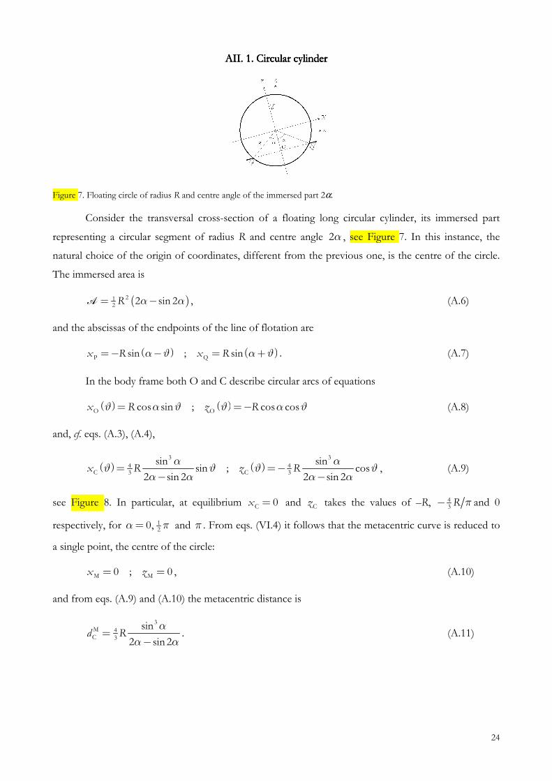
Figure 7. Floating circle of radius R and centre angle of the immersed part 2α.
Consider the transversal cross-section of a floating long circular cylinder, its immersed part
representing a circular segment of radius R and centre angle 2α , see Figure 7. In this instance, the
natural choice of the origin of coordinates, different from the previous one, is the centre of the circle.
The immersed area is
( )212 2 sin 2R α α−=A , (A.6)
and the abscissas of the endpoints of the line of flotation are
( ) ( )P Qsin ; sinx R x Rα ϑ α ϑ=− − = + . (A.7)
In the body frame both O and C describe circular arcs of equations
( ) ( )O Ocos sin ; cos cosx zR Rα ϑϑ α ϑϑ =−= (A.8)
and, cf. eqs. (A.3), (A.4),
( ) ( )4C
43
3
3
3
C
sin sin
2 sisin ;
n 2 2 sis
n 2cox zR R
α αϑ ϑ
α α α αϑ ϑ= =−
− −, (A.9)
see Figure 8. In particular, at equilibrium C 0x = and Cz takes the values of –R, 43 R π− and 0
respectively, for 120,α π= and π . From eqs. (VI.4) it follows that the metacentric curve is reduced to
a single point, the centre of the circle:
M M0 ; 0x z= = , (A.10)
and from eqs. (A.9) and (A.10) the metacentric distance is
3M 4C 3
sin
2 sin 2d R
α
α α−= . (A.11)
25
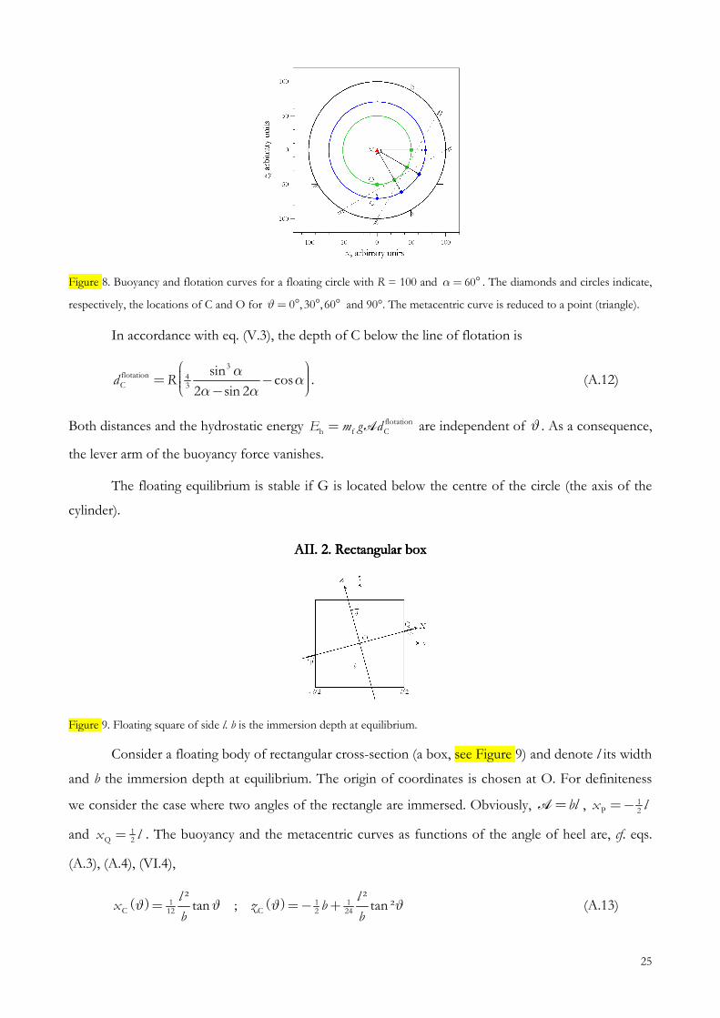
Figure 8. Buoyancy and flotation curves for a floating circle with R = 100 and 60α= ° . The diamonds and circles indicate,
respectively, the locations of C and O for 0 , 30 , 60ϑ= ° ° ° and 90°. The metacentric curve is reduced to a point (triangle).
In accordance with eq. (V.3), the depth of C below the line of flotation is
43
3flotationC
sin
2co
2s
sind R
α
αα
α
= − − . (A.12)
Both distances and the hydrostatic energy flotation
h f CE m g d= A are independent of ϑ . As a consequence,
the lever arm of the buoyancy force vanishes.
The floating equilibrium is stable if G is located below the centre of the circle (the axis of the
cylinder).
AAAAII. II. II. II. 2222. Rectangular box. Rectangular box. Rectangular box. Rectangular box
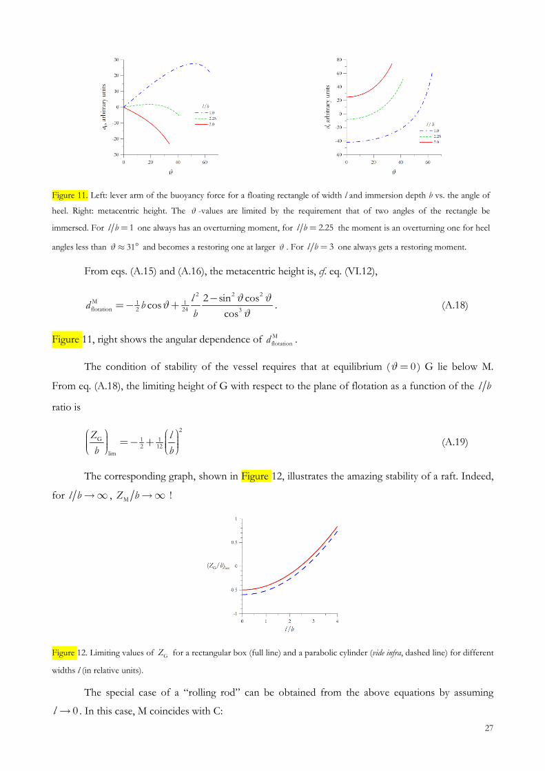
Figure 9. Floating square of side l. b is the immersion depth at equilibrium.
Consider a floating body of rectangular cross-section (a box, see Figure 9) and denote l its width
and b the immersion depth at equilibrium. The origin of coordinates is chosen at O. For definiteness
we consider the case where two angles of the rectangle are immersed. Obviously, bl=A , 1P 2x l=−
and 1Q 2x l= . The buoyancy and the metacentric curves as functions of the angle of heel are, cf. eqs.
(A.3), (A.4), (VI.4),
( ) ( )1 1 1C C12 2 24
² ²tan ; tan ²
l lx z b
b bϑ ϑ ϑ ϑ= =− + (A.13)

26
and
( ) ( )31 1 1M M12 2 24
² ² 3tan ; 1
cos ²
l lx z b
b bϑ ϑ ϑ
ϑ
=− =− + − . (A.14)
Both curves are illustrated in Figure 10. The metacentric curve is “V”-shaped, and for the metacentric
distance we get
MC 2 3
11
² 1
cos
ld
b ϑ= . (A.15)
The depth of C below the line of flotation and the hydrostatic energy are, respectively,
cf. eq. (V.3),
flotation 1 1C C 24 2
floh
ta oCf
ti n
sin ²cos
cos
²ld Z b
b
E g d
ϑϑ
ϑ
µ=
=− = +
A
. (A.16)
Figure 10. Buoyancy and metacentric curves for a floating square with l = 200 and b = 100. The diamonds and triangles
indicate, respectively, the locations of C and M for 0 ,15 , 30ϑ= ° ° ° and 45°. The flotation curve is reduced to a point
(circle).
The lever arm of the buoyancy force, in accordance with eq. (V.17), is
2
1 12 1 22 2h
cos
11 1 sin
l
ba b
ϑϑ
− + =
. (A.17)
The angular dependence of ah is shown in Figure 11, left. For larger bodies Eh is minimal at
equilibrium, 0ϑ= and increases with the angle of heel, cf. eq. (A.16); the sign of ah is opposite to that of
ϑ , corresponding to a restoring moment. For narrower body an opposite behaviour is observed: at
equilibrium Eh is maximal, so that ah and ϑ have the same sign, corresponding to an overturning
moment. In the vicinity of equilibrium the change in the sign of ah takes place at a critical value
6l b = .
27
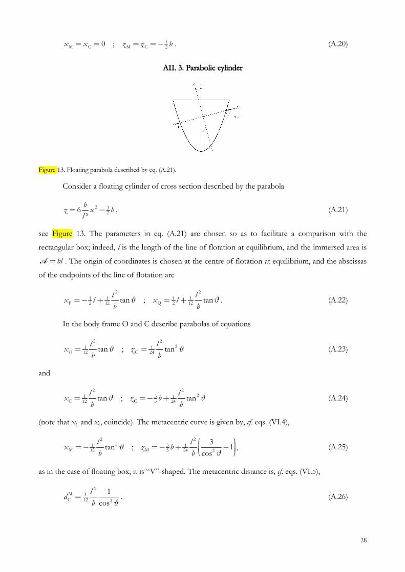
Figure 11. Left: lever arm of the buoyancy force for a floating rectangle of width l and immersion depth b vs. the angle of
heel. Right: metacentric height. The ϑ -values are limited by the requirement that of two angles of the rectangle be
immersed. For 1l b = one always has an overturning moment, for 2.25l b = the moment is an overturning one for heel
angles less than 31ϑ≈ ° and becomes a restoring one at larger ϑ . For 3l b = one always gets a restoring moment.
From eqs. (A.15) and (A.16), the metacentric height is, cf. eq. (VI.12),
2 2 2
1 12 2
M
flot 3ation 4
2 sin coscos
cosd
lb
b
ϑϑ
ϑ
ϑ= +
−− . (A.18)
Figure 11, right shows the angular dependence of M
flotationd .
The condition of stability of the vessel requires that at equilibrium ( 0ϑ= ) G lie below M.
From eq. (A.18), the limiting height of G with respect to the plane of flotation as a function of the l b
ratio is
2
1 12 12
G
lim
Z
b
l
b
= + − (A.19)
The corresponding graph, shown in Figure 12, illustrates the amazing stability of a raft. Indeed,
for l b →∞ , MZ b →∞ !
Figure 12. Limiting values of GZ for a rectangular box (full line) and a parabolic cylinder (vide infra, dashed line) for different
widths l (in relative units).
The special case of a “rolling rod” can be obtained from the above equations by assuming
0l → . In this case, M coincides with C:
28
1M C M C 20 ;x x z z b= = = =− . (A.20)
AAAAII. II. II. II. 3. Parabolic cylinder3. Parabolic cylinder3. Parabolic cylinder3. Parabolic cylinder
Figure 13. Floating parabola described by eq. (A.21).
Consider a floating cylinder of cross section described by the parabola
2 326
²
bz x b
l= − , (A.21)
see Figure 13. The parameters in eq. (A.21) are chosen so as to facilitate a comparison with the
rectangular box; indeed, l is the length of the line of flotation at equilibrium, and the immersed area is
bl=A . The origin of coordinates is chosen at the centre of flotation at equilibrium, and the abscissas
of the endpoints of the line of flotation are
2 2
1 1 1 1P Q2 12 2 12tan ; tan
l lx l x l
b bϑ ϑ=− + = + . (A.22)
In the body frame O and C describe parabolas of equations
2 221 1
O O12 24tan ; tanl l
x zb b
ϑ ϑ= = (A.23)
and
2 2231 1
C C12 5 24tan ; tanl l
x z bb b
ϑ ϑ= =− + (A.24)
(note that xC and xO coincide). The metacentric curve is given by, cf. eqs. (VI.4),
2 23 31 1
M M12 5 24 2
3tan ; 1
cos
l lx z b
b bϑ
ϑ
=− =− + − , (A.25)
as in the case of floating box, it is “V”-shaped. The metacentric distance is, cf. eqs. (VI.5),
2M 1C 12 3
1
cos
ld
b ϑ= . (A.26)
29
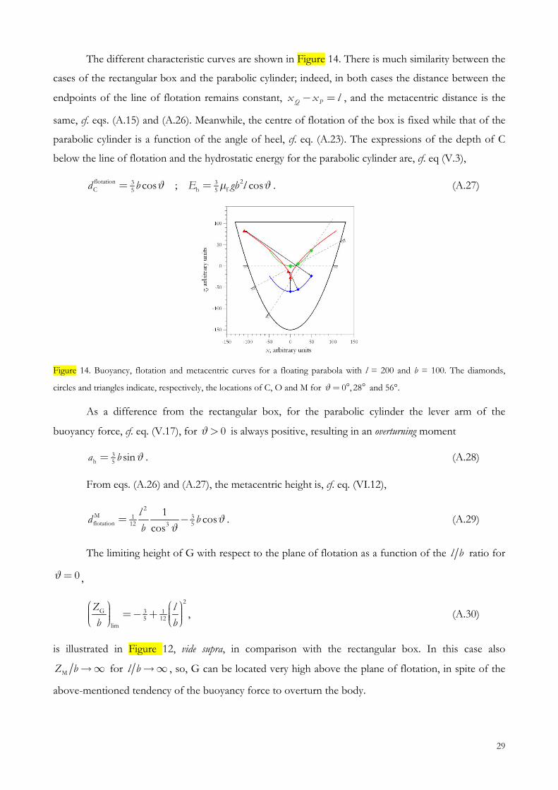
The different characteristic curves are shown in Figure 14. There is much similarity between the
cases of the rectangular box and the parabolic cylinder; indeed, in both cases the distance between the
endpoints of the line of flotation remains constant, Q Px x l− = , and the metacentric distance is the
same, cf. eqs. (A.15) and (A.26). Meanwhile, the centre of flotation of the box is fixed while that of the
parabolic cylinder is a function of the angle of heel, cf. eq. (A.23). The expressions of the depth of C
below the line of flotation and the hydrostatic energy for the parabolic cylinder are, cf. eq (V.3),
flotatio 23 3h5C f5
n cos ; cosgb E b ld ϑµϑ= = . (A.27)
Figure 14. Buoyancy, flotation and metacentric curves for a floating parabola with l = 200 and b = 100. The diamonds,
circles and triangles indicate, respectively, the locations of C, O and M for 0 , 28ϑ= ° ° and 56°.
As a difference from the rectangular box, for the parabolic cylinder the lever arm of the
buoyancy force, cf. eq. (V.17), for 0ϑ> is always positive, resulting in an overturning moment
3h 5 sinba ϑ= . (A.28)
From eqs. (A.26) and (A.27), the metacentric height is, cf. eq. (VI.12),
2
3112
Mflot n 5a io 3t
1cos
cosd
lb
bϑ
ϑ−= . (A.29)
The limiting height of G with respect to the plane of flotation as a function of the l b ratio for
0ϑ= ,
2
3 15 12
G
lim
Z
b
l
b
= + − , (A.30)
is illustrated in Figure 12, vide supra, in comparison with the rectangular box. In this case also
MZ b →∞ for l b →∞ , so, G can be located very high above the plane of flotation, in spite of the
above-mentioned tendency of the buoyancy force to overturn the body.

30
AAAAII. II. II. II. 4. Elliptic cylinder4. Elliptic cylinder4. Elliptic cylinder4. Elliptic cylinder
Figure 15. Floating ellipse of semi-axes a and b.
Consider an elliptic cylinder, see Figure 15, of cross-section described by
2 2ab
za
x± −= . (A.31)
where a and b are, respectively, the semi-major and semi-minor axes. As in the case of the circular
cylinder, the origin of coordinates is chosen at the centre of the transversal cross-section. To simplify
the formulae, we limit ourselves to the case of half-submerged cylinder, so that the line of flotation
always passes through its centre and the area of its immersed half is 12 abπ=A . Below we use the
notation
( ) 2 2 2 2sin cosR a bϑ ϑ ϑ= + (A.32)
( ( )R ϑ is the radius of the same ellipse turned through the angle 12ϑ π+ ).
In a position inclined through an angle ϑ the line of flotation meets the ellipse at the points
( )P,Q
cosabx
R
ϑ
ϑ=∓ . (A.33)
The coordinates of C are
( ) ( )
2 2
4 4C C3 3
sin cos;
a bx z
R R
ϑ ϑ
π ϑ π ϑ= =− , (A.34)
and from eqs. (VI.4) one calculates the location of the metacentre:
( )( )
( )( )
2 2 2 3 2 2 2 3
4 4M M3 33 3
sin cos;
a a b b a bx z
R R
ϑ ϑ
π ϑ π ϑ
− −= = . (A.35)
The buoyancy and metacentric curves are shown in Figure 16 for rolling about two equilibrium
states, respectively, with the major axis parallel and perpendicular to the line of flotation. In the first
case the metacentric curve is “Λ”-shaped while in the second case it is “V”-shaped. From eqs. (A.34),
(A.35) the metacentric distance is, cf. eq. (VI.5),
31
( )
2 2M 4C 3 3
a bd
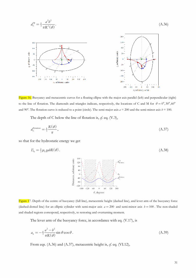
Rπ ϑ= . (A.36)
Figure 16. Buoyancy and metacentric curves for a floating ellipse with the major axis parallel (left) and perpendicular (right)
to the line of flotation. The diamonds and triangles indicate, respectively, the locations of C and M for 0 , 30 , 60ϑ= ° ° °
and 90°. The flotation curve is reduced to a point (circle). The semi-major axis a = 200 and the semi-minor axis b = 100.
The depth of C below the line of flotation is, cf. eq. (V.3),
( )flotation 4C 3
Rd
π
ϑ= , (A.37)
so that for the hydrostatic energy we get
( )2h f3
E gabRµ ϑ= . (A.38)
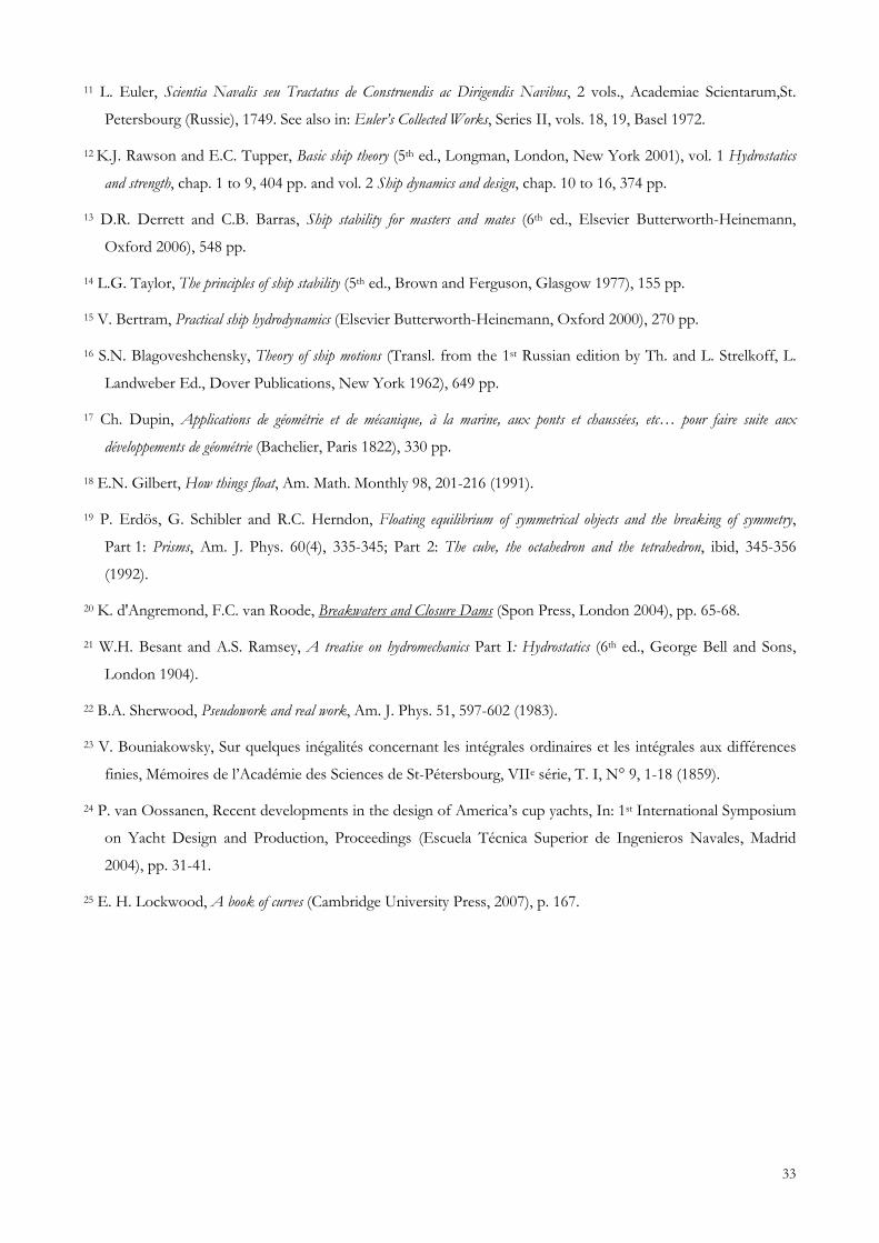
Figure 17. Depth of the centre of buoyancy (full line), metacentric height (dashed line), and lever arm of the buoyancy force
(dashed-dotted line) for an elliptic cylinder with semi-major axis 200a = and semi-minor axis 100b = . The non-shaded
and shaded regions correspond, respectively, to restoring and overturning moment.
The lever arm of the buoyancy force, in accordance with eq. (V.17), is
( )
2
h 3
2
4 cosin saR
a bϑ
πϑ
ϑ
−=− . (A.39)
From eqs. (A.36) and (A.37), metacentric height is, cf. eq. (VI.12),

32
( )
( )
2 2M 4flotation 3
4
3
a b
R
Rd
ϑ
π ϑ
−= . (A.40)
Figure 17 shows the angular dependence of the locations of C and M with respect to the line of
flotation as well as the lever arm of the buoyancy force with respect to O. At 0, 180ϑ= ° the major
axis is horizontal; the depth of C and the hydrostatic energy are minimal; the sign of ah is opposite to
that of the deviation from equilibrium, corresponding to a restoring moment. At 90ϑ= ° the major
axis is vertical; the depth of C and the hydrostatic energy are maximal; the signs of ah and of the
deviation from equilibrium, 90ϑ− ° are the same, corresponding to an overturning moment. However,
stable equilibrium corresponds to the minimum of the total potential energy and not to that of the
hydrostatic energy only. For 0ϑ= the metacentric height is maximal and in the case shown in
Figure 17 equilibrium remains stable for G located up to ca. 127 units above the line of flotation. On the
other hand, for 90ϑ=± ° the metacentric height is minimal and in order to preserve stable
equilibrium, G should be located deeper than ca. 63.7 units below the line of flotation.
ReferencesReferencesReferencesReferences
1 The works of Archimedes (ed. T.L. Heath, Adamant Media Corporation 2005), 518 pp.
2 F. M. White, Fluid mechanics (3rd edition, McGraw-Hill, New York 1994).
3 K.L. Kumar, Engineering mechanics (3rd edition, Tata McGraw-Hill, New Delhi 2003), p. 9.
4 R. Wormell, Wormell’s mechanic, Nature 5, 63 (1871).
5 V. Giles, J. B. Evett and Ch. Liu, Theory and problems of fluids mechanics and hydraulics (Schaum's outline series;
McGraw-Hill Inc., New York 1994).
6 H. Benson, University physics (John Wiley & Sons, New York 1996), p. 292.
7777 A. Biran, Ship hydrostatics and stability (1st ed., Elsevier Butterworth-Heinemann, Oxford 2003), 344 pp.
8 R. Comolet, Mécanique expérimentale des fluides, T. I: Statique et dynamique des fluides non visqueux (Masson, Paris
1990).
9 J.L. Herder and A.L. Schwab, On dynamically equivalent force systems and their application to the balancing of a broom or the
stability of a shoe box, in: Proceedings of DETC’04 ASME Design Engineering Technical Conferences and
Computers and Information in Engineering Conference (ASME, New York 2004), pp. 1-11.
10 P. Bouguer, Traité du Navire, de sa construction, et de ses mouvemens (Jombert, Paris, 1746), 682 pp. See a summary of
the Bouguer’s Treatise in: H. Nowacki and L.D. Ferreiro, Historical roots of the theory of hydrostatic stability of ships
(Max-Planck-Institut für Wissenschaftsgeschichte Preprint 237, Berlin 2003), 39 pp.
33
11 L. Euler, Scientia Navalis seu Tractatus de Construendis ac Dirigendis Navibus, 2 vols., Academiae Scientarum,St.
Petersbourg (Russie), 1749. See also in: Euler’s Collected Works, Series II, vols. 18, 19, Basel 1972.
12 K.J. Rawson and E.C. Tupper, Basic ship theory (5th ed., Longman, London, New York 2001), vol. 1 Hydrostatics
and strength, chap. 1 to 9, 404 pp. and vol. 2 Ship dynamics and design, chap. 10 to 16, 374 pp.
13 D.R. Derrett and C.B. Barras, Ship stability for masters and mates (6th ed., Elsevier Butterworth-Heinemann,
Oxford 2006), 548 pp.
14 L.G. Taylor, The principles of ship stability (5th ed., Brown and Ferguson, Glasgow 1977), 155 pp.
15 V. Bertram, Practical ship hydrodynamics (Elsevier Butterworth-Heinemann, Oxford 2000), 270 pp.
16 S.N. Blagoveshchensky, Theory of ship motions (Transl. from the 1st Russian edition by Th. and L. Strelkoff, L.
Landweber Ed., Dover Publications, New York 1962), 649 pp.
17 Ch. Dupin, Applications de géométrie et de mécanique, à la marine, aux ponts et chaussées, etc… pour faire suite aux
développements de géométrie (Bachelier, Paris 1822), 330 pp.
18 E.N. Gilbert, How things float, Am. Math. Monthly 98, 201-216 (1991).
19 P. Erdös, G. Schibler and R.C. Herndon, Floating equilibrium of symmetrical objects and the breaking of symmetry,
Part 1: Prisms, Am. J. Phys. 60(4), 335-345; Part 2: The cube, the octahedron and the tetrahedron, ibid, 345-356
(1992).
20 K. d'Angremond, F.C. van Roode, Breakwaters and Closure Dams (Spon Press, London 2004), pp. 65-68.
21 W.H. Besant and A.S. Ramsey, A treatise on hydromechanics Part I: Hydrostatics (6th ed., George Bell and Sons,
London 1904).
22 B.A. Sherwood, Pseudowork and real work, Am. J. Phys. 51, 597-602 (1983).
23 V. Bouniakowsky, Sur quelques inégalités concernant les intégrales ordinaires et les intégrales aux différences
finies, Mémoires de l’Académie des Sciences de St-Pétersbourg, VIIe série, T. I, N° 9, 1-18 (1859).
24 P. van Oossanen, Recent developments in the design of America’s cup yachts, In: 1st International Symposium
on Yacht Design and Production, Proceedings (Escuela Técnica Superior de Ingenieros Navales, Madrid
2004), pp. 31-41.
25 E. H. Lockwood, A book of curves (Cambridge University Press, 2007), p. 167.
Related Documents