© February 24, 2017 Dr. Lynn Fuller MEMS Signal Conditioning Circuits Page 1 Rochester Institute of Technology Microelectronic Engineering ROCHESTER INSTITUTE OF TECHNOLOGY MICROELECTRONIC ENGINEERING MEMS Signal Conditioning Circuits Dr. Lynn Fuller Electrical and Microelectronic Engineering Rochester Institute of Technology 82 Lomb Memorial Drive Rochester, NY 14623-5604 Email: [email protected] Dr. Fuller’s Webpage: http://people.rit.edu/lffeee MicroE Webpage: http:// www.rit.edu/microelectronic/ 2-24-2017 Signal_Conditioning.ppt

Welcome message from author
This document is posted to help you gain knowledge. Please leave a comment to let me know what you think about it! Share it to your friends and learn new things together.
Transcript
© February 24, 2017 Dr. Lynn Fuller
MEMS Signal Conditioning Circuits
Page 1
Rochester Institute of Technology
Microelectronic Engineering
ROCHESTER INSTITUTE OF TECHNOLOGYMICROELECTRONIC ENGINEERING
MEMS Signal Conditioning Circuits
Dr. Lynn FullerElectrical and Microelectronic Engineering
Rochester Institute of Technology82 Lomb Memorial DriveRochester, NY 14623-5604
Email: [email protected]. Fuller’s Webpage: http://people.rit.edu/lffeee
MicroE Webpage: http://www.rit.edu/microelectronic/
2-24-2017 Signal_Conditioning.ppt
© February 24, 2017 Dr. Lynn Fuller
MEMS Signal Conditioning Circuits
Page 2
Rochester Institute of Technology
Microelectronic Engineering
OUTLINE
Op Amp IntroductionInverting AmplifierNon-inverting AmplifierUnity Gain BufferIntegratorInverting SummerDifference AmplifierComparator, Comparator with hysteresisVoltage AmplifierCurrent to Voltage ConverterRC OscillatorChanging AC Capacitance to VoltageChange in Resistance to VoltageDiode Temperature to VoltageResistor Bridge and Differential AmplifiersPower Op Amp CircuitReferences
© February 24, 2017 Dr. Lynn Fuller
MEMS Signal Conditioning Circuits
Page 3
Rochester Institute of Technology
Microelectronic Engineering
INTRODUCTION
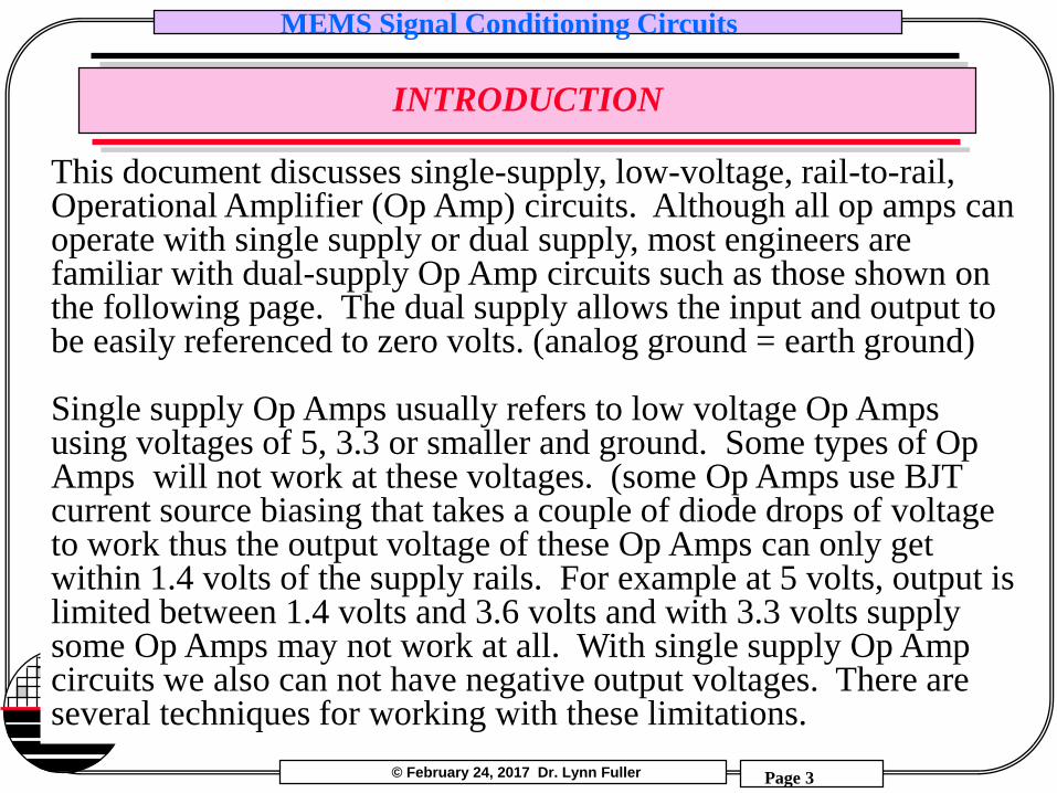
This document discusses single-supply, low-voltage, rail-to-rail, Operational Amplifier (Op Amp) circuits. Although all op amps can operate with single supply or dual supply, most engineers are familiar with dual-supply Op Amp circuits such as those shown on the following page. The dual supply allows the input and output to be easily referenced to zero volts. (analog ground = earth ground)
Single supply Op Amps usually refers to low voltage Op Amps using voltages of 5, 3.3 or smaller and ground. Some types of Op Amps will not work at these voltages. (some Op Amps use BJT current source biasing that takes a couple of diode drops of voltage to work thus the output voltage of these Op Amps can only get within 1.4 volts of the supply rails. For example at 5 volts, output is limited between 1.4 volts and 3.6 volts and with 3.3 volts supply some Op Amps may not work at all. With single supply Op Amp circuits we also can not have negative output voltages. There are several techniques for working with these limitations.
© February 24, 2017 Dr. Lynn Fuller
MEMS Signal Conditioning Circuits
Page 4
Rochester Institute of Technology
Microelectronic Engineering
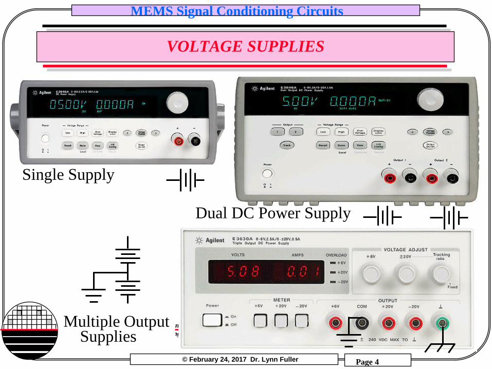
VOLTAGE SUPPLIES
Dual DC Power Supply
Single Supply
Multiple OutputSupplies
© February 24, 2017 Dr. Lynn Fuller
MEMS Signal Conditioning Circuits
Page 5
Rochester Institute of Technology
Microelectronic Engineering
CREATING A SPLIT SUPPLY FROM A SINGLE SUPPLY
Signal
Ground
Chassis
GroundEarth
Ground
Virtual
Ground
Analog
Ground
Digital
GroundCommon
Ground
Floating
Ground
Single
Supply
R
R
C
C
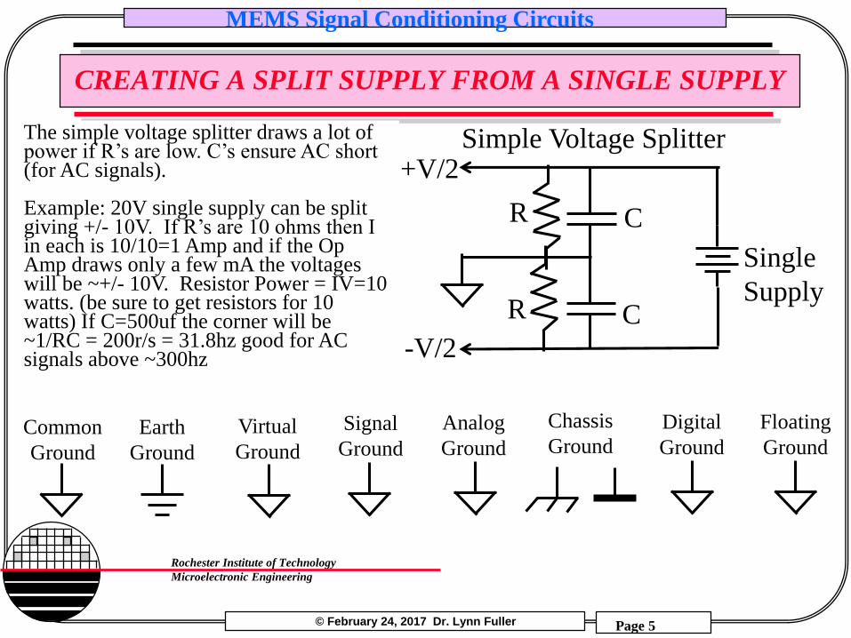
Simple Voltage Splitter+V/2
-V/2
The simple voltage splitter draws a lot of power if R’s are low. C’s ensure AC short (for AC signals).
Example: 20V single supply can be split giving +/- 10V. If R’s are 10 ohms then I in each is 10/10=1 Amp and if the Op Amp draws only a few mA the voltages will be ~+/- 10V. Resistor Power = IV=10 watts. (be sure to get resistors for 10 watts) If C=500uf the corner will be ~1/RC = 200r/s = 31.8hz good for AC signals above ~300hz
© February 24, 2017 Dr. Lynn Fuller
MEMS Signal Conditioning Circuits
Page 6
Rochester Institute of Technology
Microelectronic Engineering
VIRTUAL GROUND / VOLTAGE SPLITTER
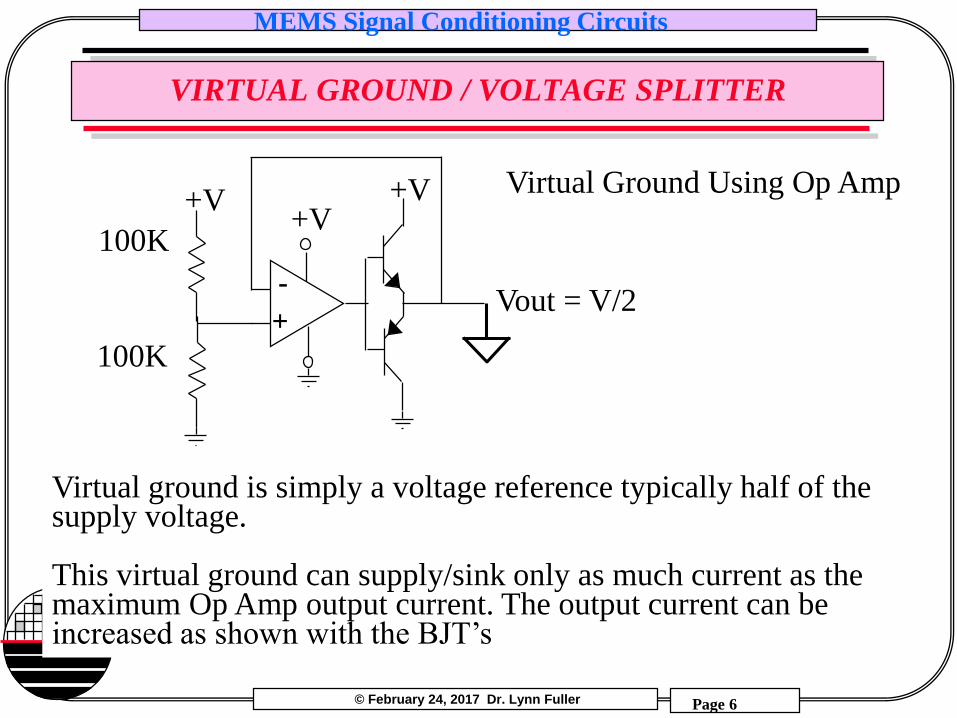
Virtual Ground Using Op Amp
Virtual ground is simply a voltage reference typically half of the supply voltage.
This virtual ground can supply/sink only as much current as the maximum Op Amp output current. The output current can be increased as shown with the BJT’s
Vout = V/2-
+
100K+V
+V+V
100K
© February 24, 2017 Dr. Lynn Fuller
MEMS Signal Conditioning Circuits
Page 7
Rochester Institute of Technology
Microelectronic Engineering
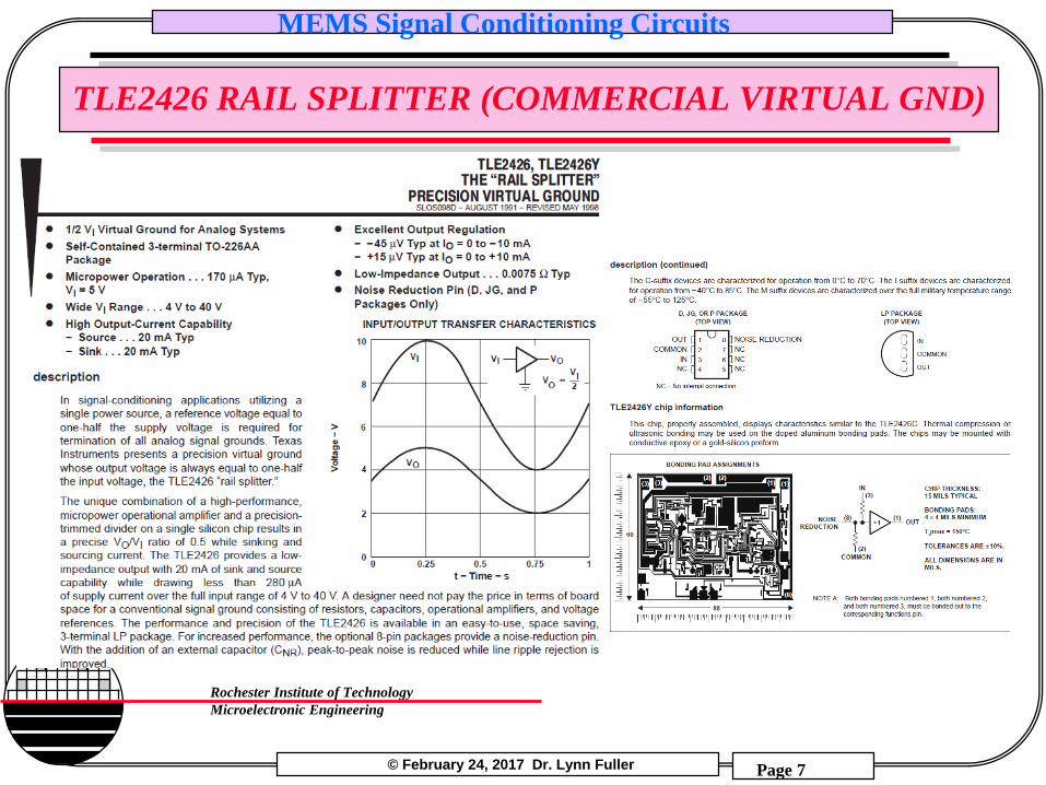
TLE2426 RAIL SPLITTER (COMMERCIAL VIRTUAL GND)
© February 24, 2017 Dr. Lynn Fuller
MEMS Signal Conditioning Circuits
Page 8
Rochester Institute of Technology
Microelectronic Engineering
OPERATIONAL AMPLIFERS
The 741 Op Amp is a general purpose bipolar (BJT) integrated circuit that has input bias current of 80nA, and input voltage of +/-15 volts @ supply maximum of +/- 18 volts. The output voltage can not go all the way to the + and - supply voltage. At a minimum supply of +/- 5 volts the output voltage can go ~6 volts p-p.
The newer Op Amps have rail-rail output swing and supply voltages as low as +/- 1.5 volts. The MOSFET input bias currents are ~ 1pA. The NJU7031 is an example of this type of Op Amp.
© February 24, 2017 Dr. Lynn Fuller
MEMS Signal Conditioning Circuits
Page 9
Rochester Institute of Technology
Microelectronic Engineering
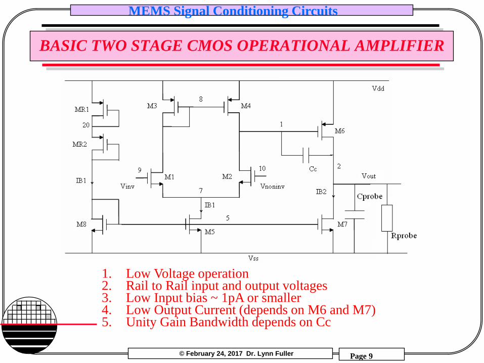
BASIC TWO STAGE CMOS OPERATIONAL AMPLIFIER
1. Low Voltage operation2. Rail to Rail input and output voltages3. Low Input bias ~ 1pA or smaller4. Low Output Current (depends on M6 and M7)5. Unity Gain Bandwidth depends on Cc
© February 24, 2017 Dr. Lynn Fuller
MEMS Signal Conditioning Circuits
Page 10
Rochester Institute of Technology
Microelectronic Engineering
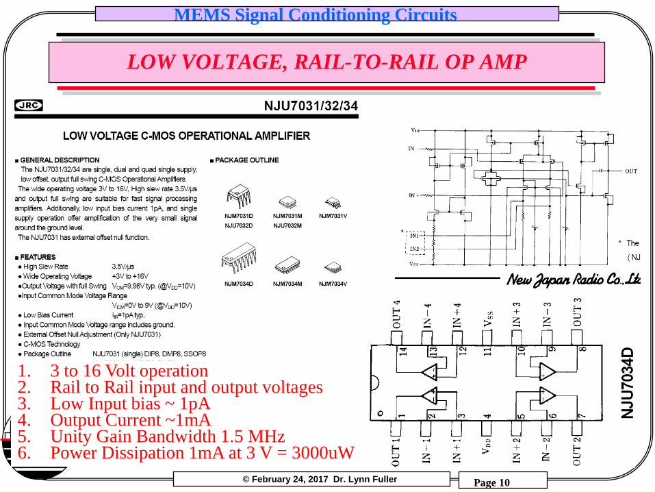
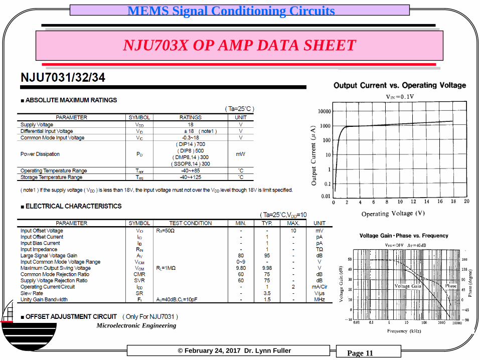
LOW VOLTAGE, RAIL-TO-RAIL OP AMP
1. 3 to 16 Volt operation2. Rail to Rail input and output voltages3. Low Input bias ~ 1pA4. Output Current ~1mA5. Unity Gain Bandwidth 1.5 MHz6. Power Dissipation 1mA at 3 V = 3000uW
© February 24, 2017 Dr. Lynn Fuller
MEMS Signal Conditioning Circuits
Page 11
Rochester Institute of Technology
Microelectronic Engineering
NJU703X OP AMP DATA SHEET
© February 24, 2017 Dr. Lynn Fuller
MEMS Signal Conditioning Circuits
Page 12
Rochester Institute of Technology
Microelectronic Engineering
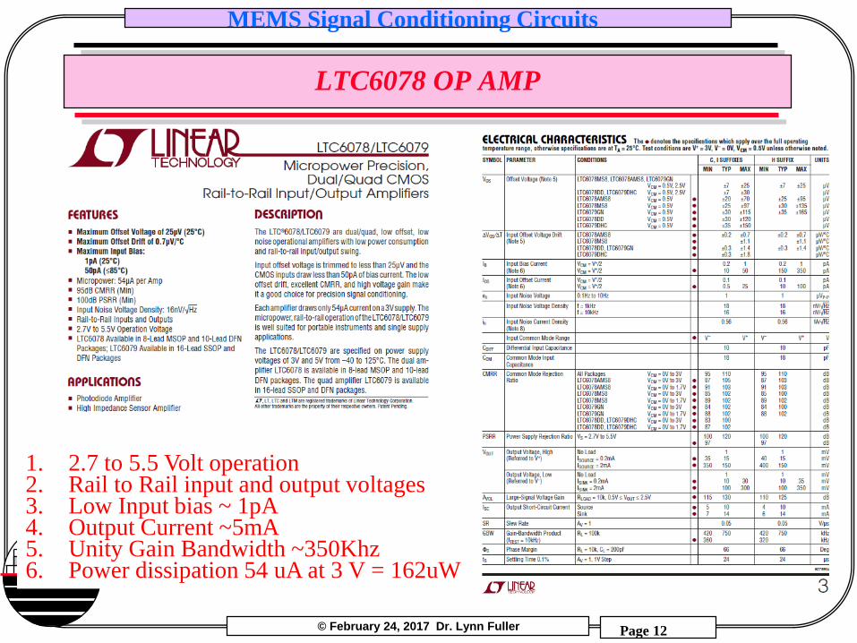
LTC6078 OP AMP
1. 2.7 to 5.5 Volt operation2. Rail to Rail input and output voltages3. Low Input bias ~ 1pA4. Output Current ~5mA5. Unity Gain Bandwidth ~350Khz6. Power dissipation 54 uA at 3 V = 162uW
© February 24, 2017 Dr. Lynn Fuller
MEMS Signal Conditioning Circuits
Page 13
Rochester Institute of Technology
Microelectronic Engineering
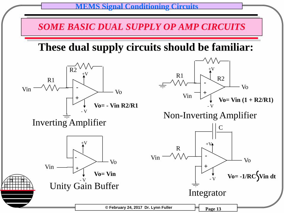
SOME BASIC DUAL SUPPLY OP AMP CIRCUITS
These dual supply circuits should be familiar:
-
+Vo
Vin
R2R1
Non-Inverting Amplifier
-
+VoVin
C
R
Integrator
Vo= Vin (1 + R2/R1)
Vo= -1/RC Vin dt
-
+
Unity Gain Buffer
VinVo
Vo= Vin
+V
- V
+V
- V
+V
- V
-
+VoVin
R2
R1
Inverting Amplifier
Vo= - Vin R2/R1
+V
- V
© February 24, 2017 Dr. Lynn Fuller
MEMS Signal Conditioning Circuits
Page 14
Rochester Institute of Technology
Microelectronic Engineering
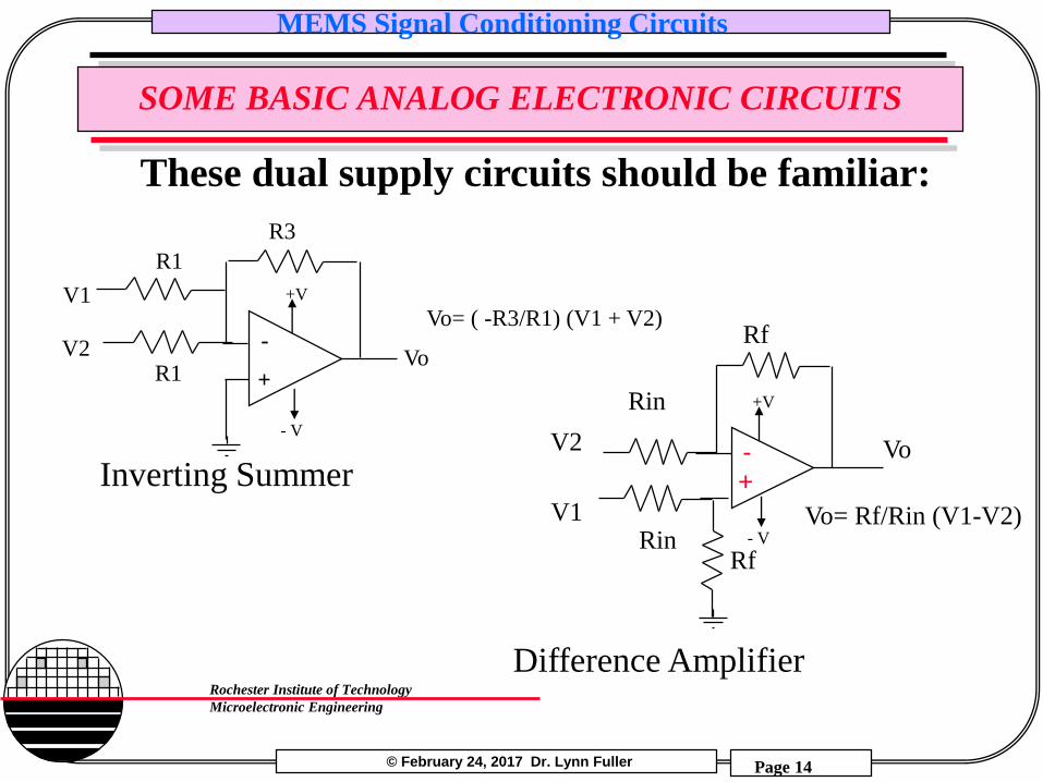
SOME BASIC ANALOG ELECTRONIC CIRCUITS
Inverting Summer
Difference Amplifier
Vo= Rf/Rin (V1-V2)
Vo-+
Rin
Rf
V1
V2
RfRin
-
+VoV2
R3
R1
V1
R1
Vo= ( -R3/R1) (V1 + V2)+V
- V
+V
- V
These dual supply circuits should be familiar:
© February 24, 2017 Dr. Lynn Fuller
MEMS Signal Conditioning Circuits
Page 15
Rochester Institute of Technology
Microelectronic Engineering
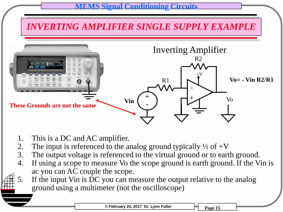
INVERTING AMPLIFIER SINGLE SUPPLY EXAMPLE
-
+ VoVin
R2
R1
Inverting Amplifier
Vo= - Vin R2/R1+V
+-
1. This is a DC and AC amplifier.2. The input is referenced to the analog ground typically ½ of +V3. The output voltage is referenced to the virtual ground or to earth ground. 4. If using a scope to measure Vo the scope ground is earth ground. If the Vin is
ac you can AC couple the scope.5. If the input Vin is DC you can measure the output relative to the analog
ground using a multimeter (not the oscilloscope)
These Grounds are not the same
© February 24, 2017 Dr. Lynn Fuller
MEMS Signal Conditioning Circuits
Page 16
Rochester Institute of Technology
Microelectronic Engineering
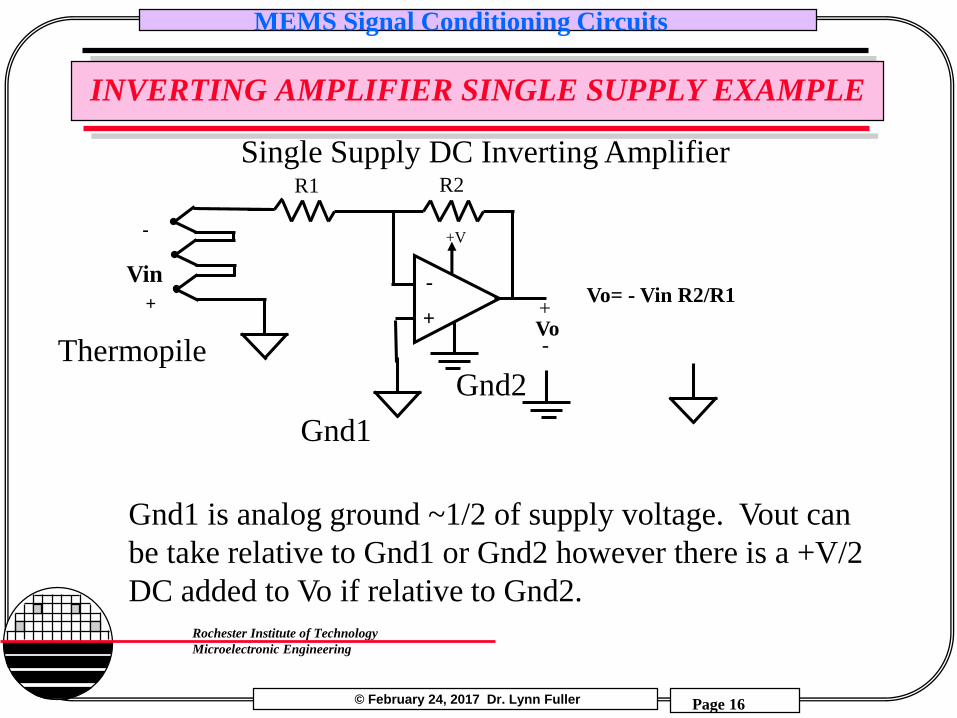
INVERTING AMPLIFIER SINGLE SUPPLY EXAMPLE
-
+
R2R1
Single Supply DC Inverting Amplifier
Vo= - Vin R2/R1
+V-
+
Vin
+
-Vo
Gnd1 is analog ground ~1/2 of supply voltage. Vout can
be take relative to Gnd1 or Gnd2 however there is a +V/2
DC added to Vo if relative to Gnd2.
Gnd1
Gnd2Thermopile
© February 24, 2017 Dr. Lynn Fuller
MEMS Signal Conditioning Circuits
Page 17
Rochester Institute of Technology
Microelectronic Engineering
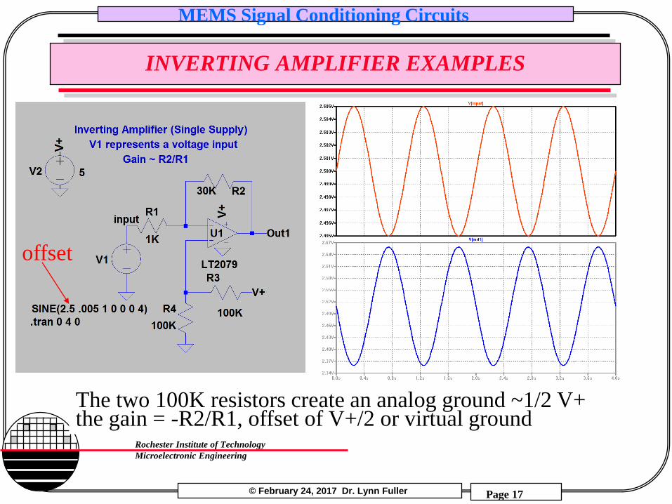
INVERTING AMPLIFIER EXAMPLES
The two 100K resistors create an analog ground ~1/2 V+the gain = -R2/R1, offset of V+/2 or virtual ground
offset
© February 24, 2017 Dr. Lynn Fuller
MEMS Signal Conditioning Circuits
Page 18
Rochester Institute of Technology
Microelectronic Engineering
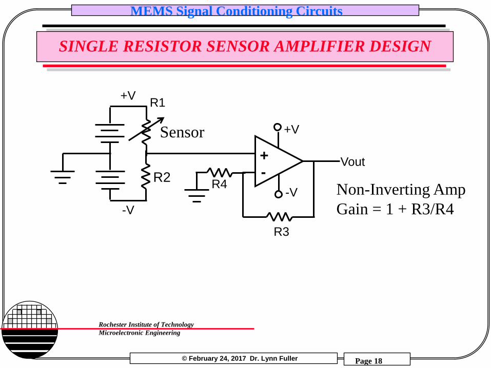
SINGLE RESISTOR SENSOR AMPLIFIER DESIGN
-V
-+
+V
-V
R1
R4
Vout
+V
R2
R3
Sensor
Non-Inverting Amp
Gain = 1 + R3/R4
© February 24, 2017 Dr. Lynn Fuller
MEMS Signal Conditioning Circuits
Page 19
Rochester Institute of Technology
Microelectronic Engineering
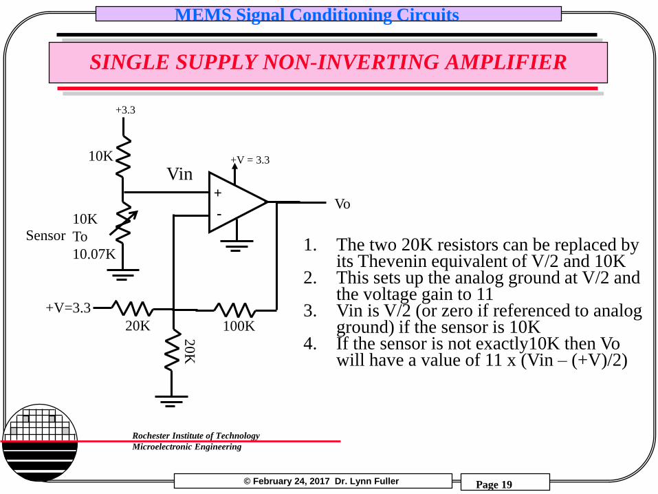
SINGLE SUPPLY NON-INVERTING AMPLIFIER
-
+
20K
+V = 3.3
20
K
+V=3.3
100K
+3.3
10K
To
10.07K
10K
Sensor
Vo
1. The two 20K resistors can be replaced by its Thevenin equivalent of V/2 and 10K
2. This sets up the analog ground at V/2 and the voltage gain to 11
3. Vin is V/2 (or zero if referenced to analog ground) if the sensor is 10K
4. If the sensor is not exactly10K then Vo will have a value of 11 x (Vin – (+V)/2)
Vin
© February 24, 2017 Dr. Lynn Fuller
MEMS Signal Conditioning Circuits
Page 20
Rochester Institute of Technology
Microelectronic Engineering
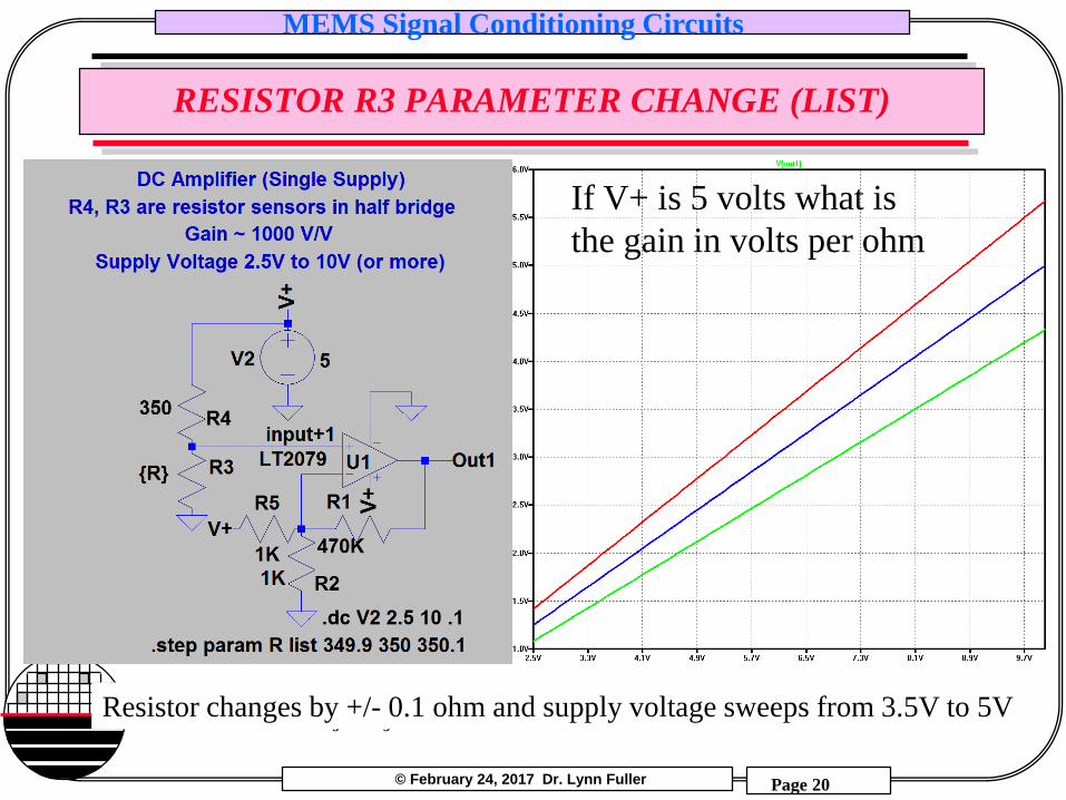
RESISTOR R3 PARAMETER CHANGE (LIST)
Resistor changes by +/- 0.1 ohm and supply voltage sweeps from 3.5V to 5V
If V+ is 5 volts what is
the gain in volts per ohm
© February 24, 2017 Dr. Lynn Fuller
MEMS Signal Conditioning Circuits
Page 21
Rochester Institute of Technology
Microelectronic Engineering
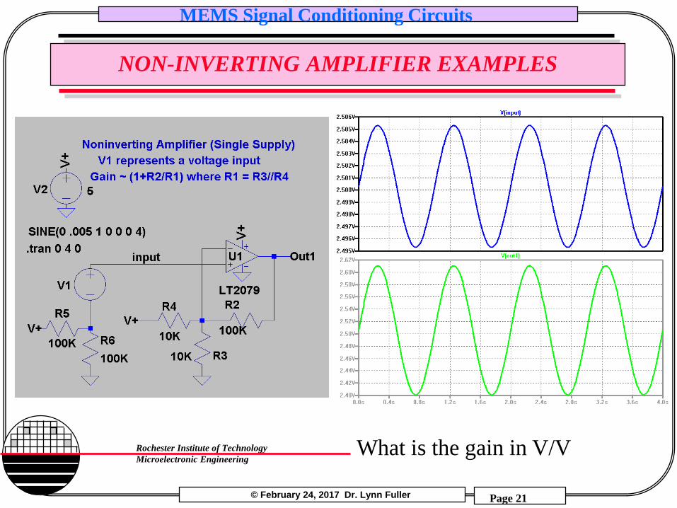
NON-INVERTING AMPLIFIER EXAMPLES
What is the gain in V/V
© February 24, 2017 Dr. Lynn Fuller
MEMS Signal Conditioning Circuits
Page 22
Rochester Institute of Technology
Microelectronic Engineering
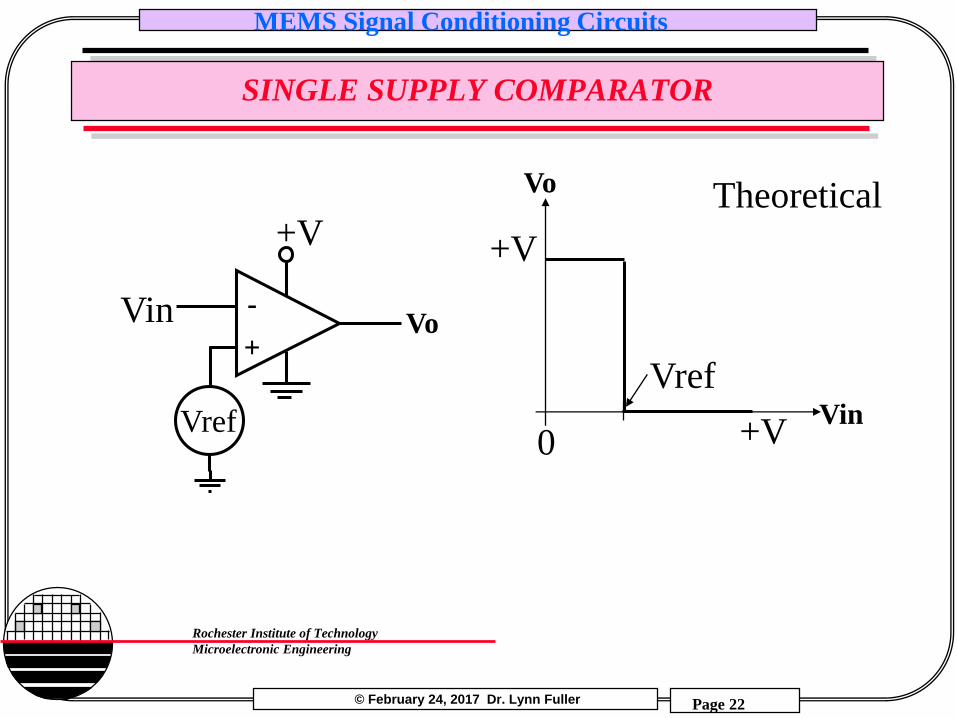
SINGLE SUPPLY COMPARATOR
-
+VoVin
Vo
VinVref
+V
Vref
+V
+V
Theoretical
0
© February 24, 2017 Dr. Lynn Fuller
MEMS Signal Conditioning Circuits
Page 23
Rochester Institute of Technology
Microelectronic Engineering
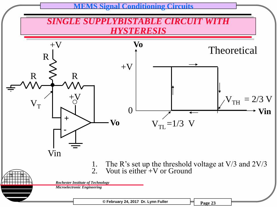
SINGLE SUPPLYBISTABLE CIRCUIT WITH HYSTERESIS
-
+Vo
Vin
+V
RR
Vo
Vin
VTH
+V
VTL
Theoretical+V
R
0VT
= 2/3 V
=1/3 V
1. The R’s set up the threshold voltage at V/3 and 2V/32. Vout is either +V or Ground
© February 24, 2017 Dr. Lynn Fuller
MEMS Signal Conditioning Circuits
Page 24
Rochester Institute of Technology
Microelectronic Engineering
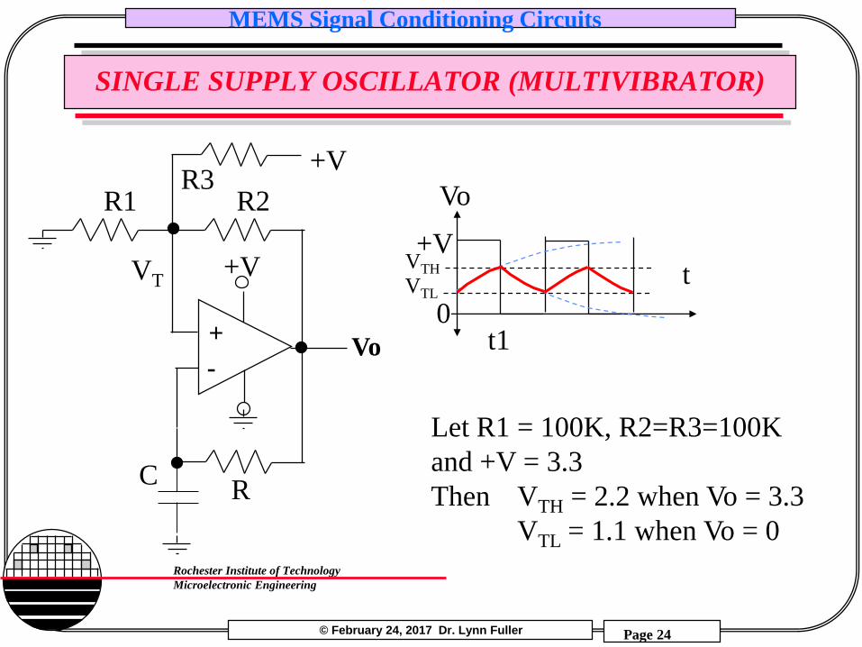
SINGLE SUPPLY OSCILLATOR (MULTIVIBRATOR)
-
+Vo
C
+V
R2R1
R
VT
+VR3
Vo
t
t1
+V
0
Let R1 = 100K, R2=R3=100K
and +V = 3.3
Then VTH = 2.2 when Vo = 3.3
VTL = 1.1 when Vo = 0
VTH
VTL
© February 24, 2017 Dr. Lynn Fuller
MEMS Signal Conditioning Circuits
Page 25
Rochester Institute of Technology
Microelectronic Engineering
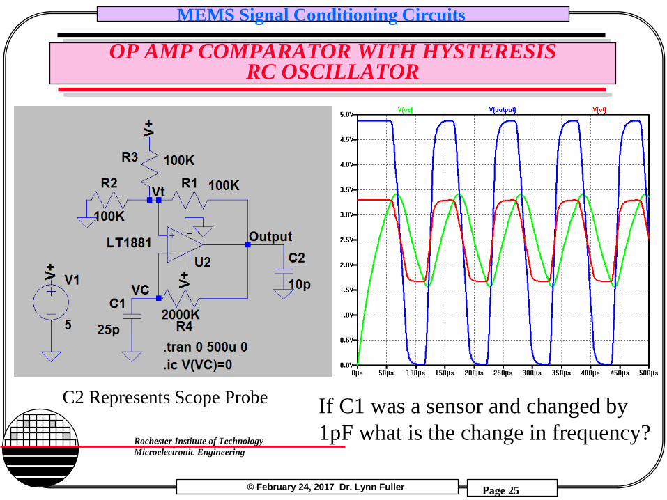
OP AMP COMPARATOR WITH HYSTERESIS RC OSCILLATOR
C2 Represents Scope Probe If C1 was a sensor and changed by
1pF what is the change in frequency?
© February 24, 2017 Dr. Lynn Fuller
MEMS Signal Conditioning Circuits
Page 26
Rochester Institute of Technology
Microelectronic Engineering
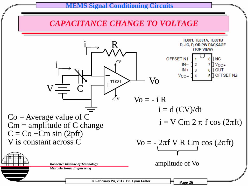
CAPACITANCE CHANGE TO VOLTAGE
+
9V
-9 V
TL081
i
V
R
CVo
i
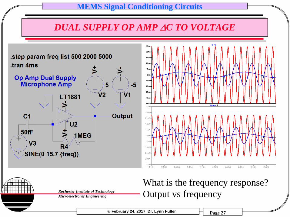
i = V Cm 2 p f cos (2pft)Co = Average value of CCm = amplitude of C changeC = Co +Cm sin (2pft)V is constant across C
Vo = - i R
i = d (CV)/dt
Vo = - 2pf V R Cm cos (2pft)
amplitude of Vo
© February 24, 2017 Dr. Lynn Fuller
MEMS Signal Conditioning Circuits
Page 27
Rochester Institute of Technology
Microelectronic Engineering
DUAL SUPPLY OP AMP DC TO VOLTAGE
What is the frequency response?
Output vs frequency
© February 24, 2017 Dr. Lynn Fuller
MEMS Signal Conditioning Circuits
Page 28
Rochester Institute of Technology
Microelectronic Engineering
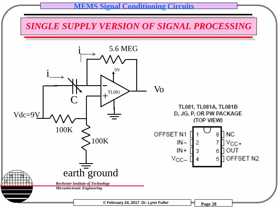
SINGLE SUPPLY VERSION OF SIGNAL PROCESSING
+
9V
TL081
i
Vdc=9V
5.6 MEG
CVo
i
100K
100K
earth ground
© February 24, 2017 Dr. Lynn Fuller
MEMS Signal Conditioning Circuits
Page 29
Rochester Institute of Technology
Microelectronic Engineering
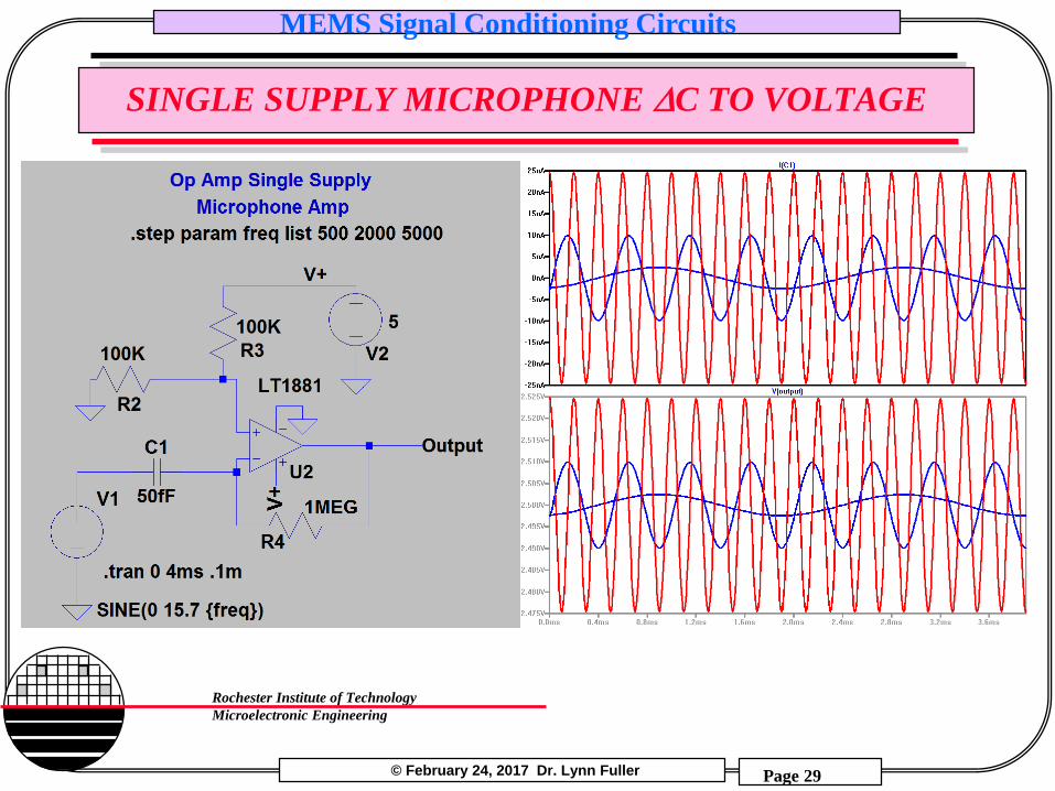
SINGLE SUPPLY MICROPHONE DC TO VOLTAGE
© February 24, 2017 Dr. Lynn Fuller
MEMS Signal Conditioning Circuits
Page 30
Rochester Institute of Technology
Microelectronic Engineering
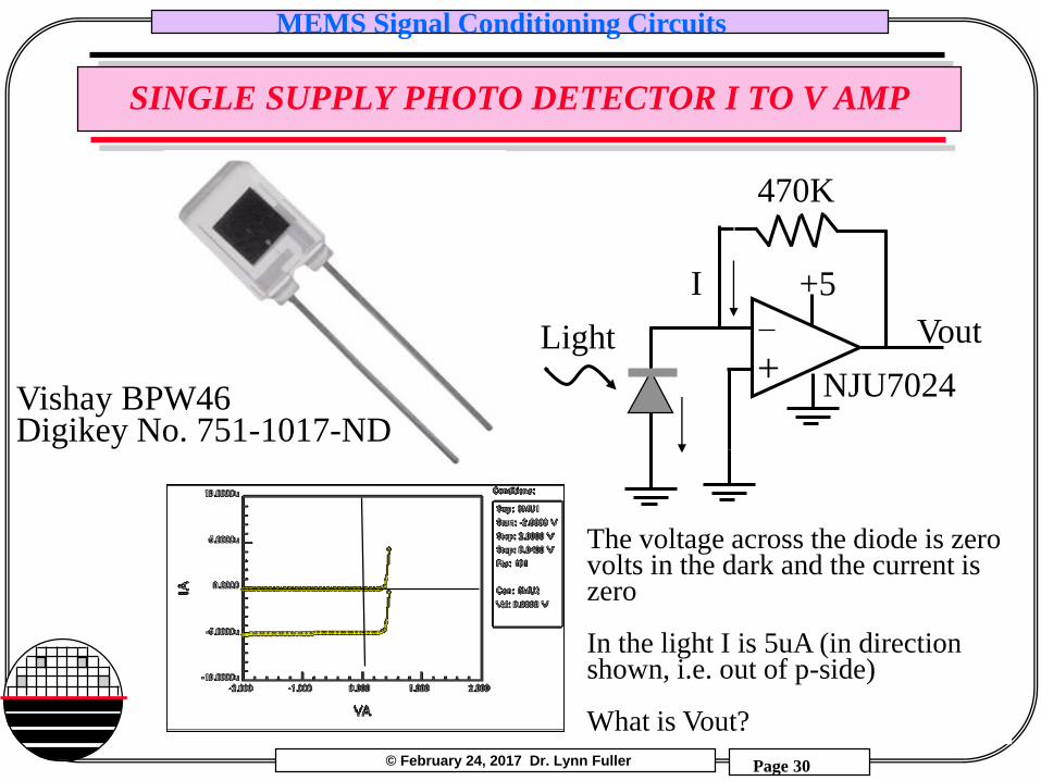
SINGLE SUPPLY PHOTO DETECTOR I TO V AMP
+Light
I
NJU7024
470K
+5
Vout
Vishay BPW46Digikey No. 751-1017-ND
The voltage across the diode is zero volts in the dark and the current is zero
In the light I is 5uA (in direction shown, i.e. out of p-side)
What is Vout?
© February 24, 2017 Dr. Lynn Fuller
MEMS Signal Conditioning Circuits
Page 31
Rochester Institute of Technology
Microelectronic Engineering
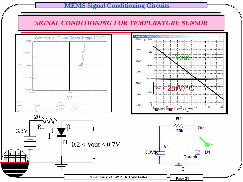
SIGNAL CONDITIONING FOR TEMPERATURE SENSOR
p
nI
3.3VR1
20K
0.2 < Vout < 0.7V
+
-
~ - 2mV/°C
Vout
© February 24, 2017 Dr. Lynn Fuller
MEMS Signal Conditioning Circuits
Page 32
Rochester Institute of Technology
Microelectronic Engineering
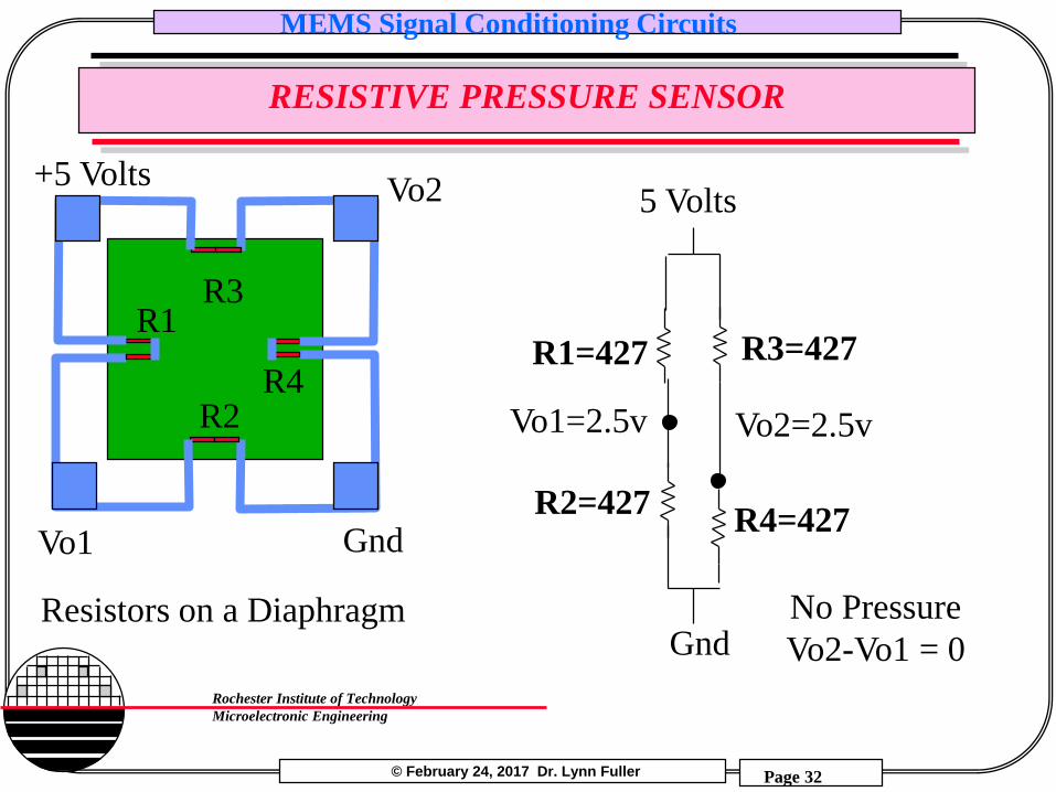
RESISTIVE PRESSURE SENSOR
R1R3
R2R4
Gnd
+5 Volts Vo2
Vo1
Resistors on a DiaphragmGnd
5 Volts
R1=427 R3=427
R2=427R4=427
Vo2=2.5vVo1=2.5v
No Pressure
Vo2-Vo1 = 0
© February 24, 2017 Dr. Lynn Fuller
MEMS Signal Conditioning Circuits
Page 33
Rochester Institute of Technology
Microelectronic Engineering
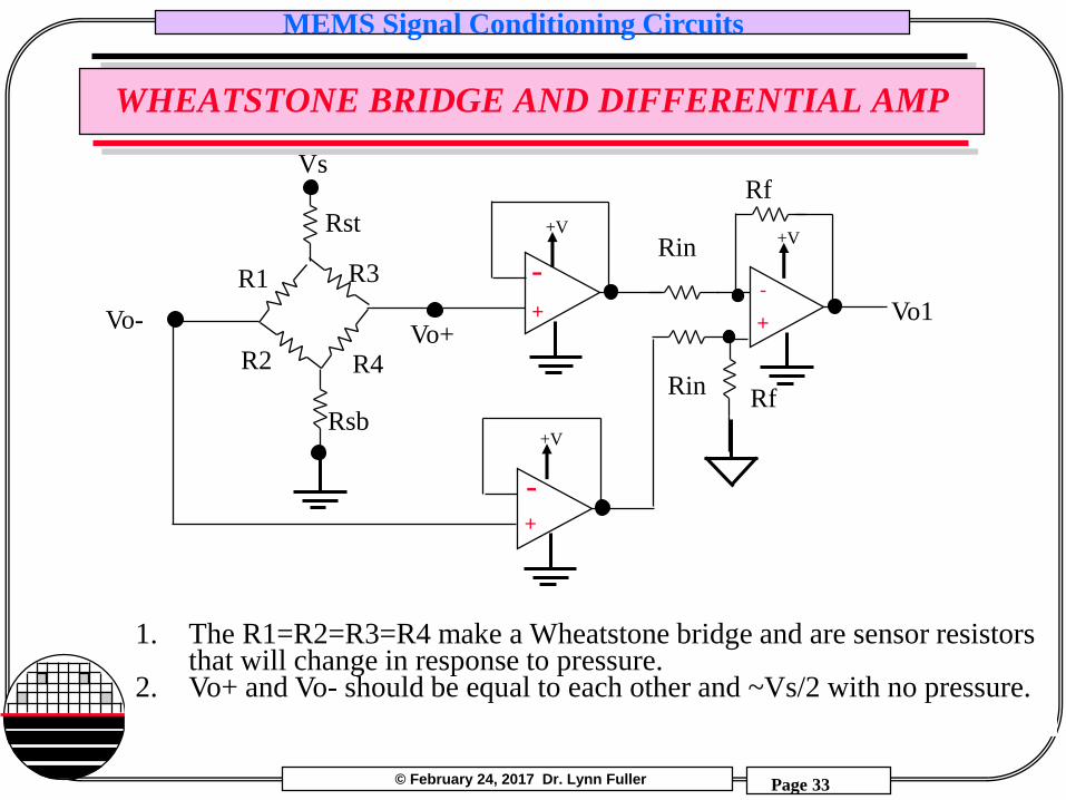
WHEATSTONE BRIDGE AND DIFFERENTIAL AMP
Vs
R1 R3
R2 R4Vo+
Rsb
Rst
Vo- Vo1-
+
Rin
Rf
-+
-+
RfRin
1. The R1=R2=R3=R4 make a Wheatstone bridge and are sensor resistors that will change in response to pressure.
2. Vo+ and Vo- should be equal to each other and ~Vs/2 with no pressure.
+V+V
+V
© February 24, 2017 Dr. Lynn Fuller
MEMS Signal Conditioning Circuits
Page 34
Rochester Institute of Technology
Microelectronic Engineering
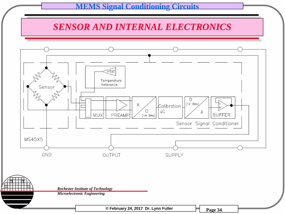
SENSOR AND INTERNAL ELECTRONICS
© February 24, 2017 Dr. Lynn Fuller
MEMS Signal Conditioning Circuits
Page 35
Rochester Institute of Technology
Microelectronic Engineering
SUMMARY
Low voltage Op Amps are often used with a single supply.
Some circuits work just fine with single supply such as the comparator.
Other circuits use a virtual ground typically ½ of the supply voltage.
Since signal generators and oscilloscopes are referenced to earth ground. Op Amp circuits need to consider this if powered by a single supply referenced to earth ground. In that case earth ground and virtual ground are at different voltages.
© February 24, 2017 Dr. Lynn Fuller
MEMS Signal Conditioning Circuits
Page 36
Rochester Institute of Technology
Microelectronic Engineering
REFERENCES
1. MOSFET Modeling with SPICE, Daniel Foty, 1997, Prentice Hall, ISBN-0-13-227935-5
2. Operation and Modeling of the MOS Transistor, 2nd Edition, Yannis Tsividis, 1999, McGraw-Hill, ISBN-0-07-065523-5
3. UTMOST III Modeling Manual-Vol.1. Ch. 5. From Silvaco International.4. ATHENA USERS Manual, From Silvaco International.5. ATLAS USERS Manual, From Silvaco International.6. Device Electronics for Integrated Circuits, Richard Muller and Theodore
Kamins, with Mansun Chan, 3rd Edition, John Wiley, 2003, ISBN 0-471-59398-27. ICCAP Manual, Hewlet Packard8. PSpice Users Guide. 9. Using Single Supply Operational Amplifiers – from Microchip10. Designing Single Supply, Low-Power Systems – from Analog Devices11. Designing Circuits for Single Supply Operation – from Linear Technology12. Single Supply Design – from TI13. Design Trade-Offs for Single-Supply Op Amps – from Maxium
© February 24, 2017 Dr. Lynn Fuller
MEMS Signal Conditioning Circuits
Page 37
Rochester Institute of Technology
Microelectronic Engineering
HOMEWORK – MEMS SIGNAL CONDITIONING
1. Do SPICE analysis for a single op amp with dual supply to amplify the output for a single resistor sensor similar to that shown on page 18.
2. If you want to measure a small value (0.1pF) slowly changing capacitance, what circuit could be used? Show it works using SPICE.
Related Documents


![Temperature compensation model of MEMS inertial …inertial sensors that are fabricated with their electronic circuits and other mechanical components on a common substrate [1]. MEMS-based](https://static.cupdf.com/doc/110x72/5e58fefc43d5e4795f258b2f/temperature-compensation-model-of-mems-inertial-inertial-sensors-that-are-fabricated.jpg)